NSWGR C LOCOMOTIVE AND TENDER KIT
|
|
|
- Dominick Fields
- 5 years ago
- Views:
Transcription
1 Australian Railway Kits ABN: Incorporating Main West Models Manufacturers, Wholesalers and Retailers of Quality Australian Model Railways PO Box 252 Warwick, Queensland, 4370 Australia Phone/Fax: Website: NSWGR C LOCOMOTIVE AND TENDER KIT E151 Manufactured Exclusively for AR Kits by DJH Engineering from Patterns owned by AR Kits PLEASE READ INSTRUCTIONS THOROUGHLY BEFORE COMMENCING ASSEMBLY CONSTRUCTION It is important to ensure that all parts are clean, free of "flash" (excess metal on castings) and fit properly. The "flash line" is easily removed from most areas by scraping gently with a sharp hobby knife - a round blade is more effective than a straight pointed type. Pull the blade along the "flash line" - several light strokes are better than a single one. Some areas are better cleaned up with 6" jewellers files. Take care not to flatten round parts by filing too heavily. All locating holes for detail fittings should be pre-drilled to the size specified in the instructions. Sometimes it is necessary to clean out these holes with a "rat tail" file; take care not to snap off the tip of the file. Gently wash the castings in warm soapy water to remove mould release residue. Etched brass items are best removed from the fret by placing the fret on a scrap piece of hard timber (e.g. Pyneboard) and cutting the tabs with a large Stanley knife - cut the tab at the point furthest away from the part, then trim the tab off close to the part with a small pair of quality side cutters. Hold small parts with a pair of flat nosed (not serrated jaws) pliers while cleaning up with jewellers files. Be careful not to distort the etchings; they are difficult to straighten if bent or twisted. Drill all required holes before assembly, noting the spigot sizes of the fittings, because some holes will be difficult to drill after parts are assembled. A detailed history of the C32 locomotives is covered in Ron Preston's book "Standards in Steam, The C32 Class", and an excellent Data Sheet is also available. Modellers are advised to check photographs of the particular locomotive they have chosen to model, also keeping in mind the era they are modelling. For assistance in general detailing, modellers are referred to the Standards in Steam, The C32 Class book by Ron Preston, Data Sheet's plan and the many photos which appear in Australian railway books and journals. These kits are designed to give many years of operating pleasure. A little extra time taken during construction will ensure that your kit will do this. It cannot be emphasised too strongly that the basis of a smoothly operating model is care when constructing the chassis and valve gear, i.e. you must double check every step. Check that the axles turn freely in their bearings, check again with the coupling rods on, then again with the connecting rods on, etc, etc. Assembly methods The two main construction methods are: (a) Low melt solder - Low melt solder is an excellent medium for use with white metal kits. It is quick and easy providing a stronger joint than can be achieved with glue. It has the added advantage of easily repairing minor casting flaws, and because of the relatively low temperature, many parts can be held in the fingers while soldering. Brass to white metal joints can also be made by "tinning" the brass first with normal solder. Low melt soldering requires the correct type of soldering iron (eg Dick Smith T2200). These irons have temperature control, as low melt solder only requires around 200 degrees centigrade. You should use special low melting point solder available from AR Kits. IT IS ADVISABLE NOT TO ATTEMPT TO SOLDER ANY CASTINGS WITH A STANDARD SOLDERING IRON Page 1
2 (b) Glue - Superglue and Plastibond are two types of glues suitable for use with this kit. Some modellers prefer to superglue major joints first then "fillet" the joint with Pastibond. Small detail parts are best glued with Superglue. Glue is not recommended for those parts needing good electrical contact, such as the tender bogies. It does not matter which method you choose but dry fitting parts will ensure a good fit. Electrical pickup. The electrical system used on these kits is called "half live". Looking from the top facing forward the locomotive chassis collects current from the live wheels on the right-hand side, shown as LS (live side) on the drawings. The tender is insulated from the locomotive chassis by a plastic bush and current is collected from the wheels on the left-hand side of the tender. Cleaning up/painting On completion, any areas which were soldered should be washed using a soft brush and methylated spirits to remove all traces of flux, if this is not done the paint will not adhere properly to these areas. Alternatively an excellent pressure pack flux remover is also available from Dick smith stores. Then wash thoroughly in warm soapy water. Rinse with clean water and allow to dry thoroughly before applying a suitable self-etch primer. Spare Parts Spare parts are available on a replacement basis. Should any part be missing or damaged contact AR Kits for a replacement. Should you have any problems with the Mashima motor please do not attempt to repair it yourself - return the motor to us. Mashima will not replace motors which have been tampered with. Should you have any queries or problems with construction please drop us a note and we will do our best to advise. Likewise we would be pleased to hear any suggestions you may have for improving the kits or instructions. General The following drill sizes are required: 0.5mm, 0.6mm, 0.7mm, 0.8mm, 0.9mm, 1.0mm, 1.2mm, 1.5mm, 1.6mm, 1.9mm, 2.Omm, 2.1mm, 3.7mm. During construction refer to the drawings at all times. A number of parts are quite similar, so double check if in doubt. Note that attached to the instructions is a photocopy of the lost wax brass castings sprues with each part numbered for easy identification. In the general instructions the part numbers are shown in brackets. The instructions sometimes refer to the right hand (R/H) and left hand (L/H) side. This is taken as viewing the model from above and looking forward. To minimise the risk of losing parts, do not remove them from the etched fret or the plastic packing until you are ready to use them. We recommend that you start construction with the tender. Safety First These models are not toys and are not suitable for young children. White metal castings contain lead and modellers are advised to wash their hands after working with unpainted white metal castings. When using superglue, solder or when spray painting, ensure your work area is well ventilated Tender Drawing T1(Parts TI - T20) Take tender back and sides (T2) and fold to form 90 degree corners - note that fold lines are etched on the inside of the corners to assist in folding. At this point solder the bogie centre pivots (T10x2) to the underside of the tender floor. Now fix the back and sides onto the tender floor (T1). Bend the door shapes on the tender front (T3) as shown in the small insert drawing 1, then fix to the floor and sides. Bend the coal trough (T4) and fix to the front (T3) noting that fold on the rear coal trough helps to locate this part. Now fix in place the rake irons support (T20). Fit buffer beam (T32 from drawing 2) onto the underneath of the floor, noting that the two vertical spigots form the lamp irons. Fit the side valances (T6x2) followed by front valance (T5). Check that the assembly is "square" before adding the front steps (T7x2). Fold up edges of front step treads (T8x2) before adding to front steps. Fit the brake cylinder (T17) to the tender floor. Prior to fixing the tender top (T18) into the tender body, some modellers may prefer to fit parts T21, T22, T29, T30 and the grab rail from drawing 2 before fitting the tender top in place. Fit the coal plates (T19x2) to the tender top. Page 2
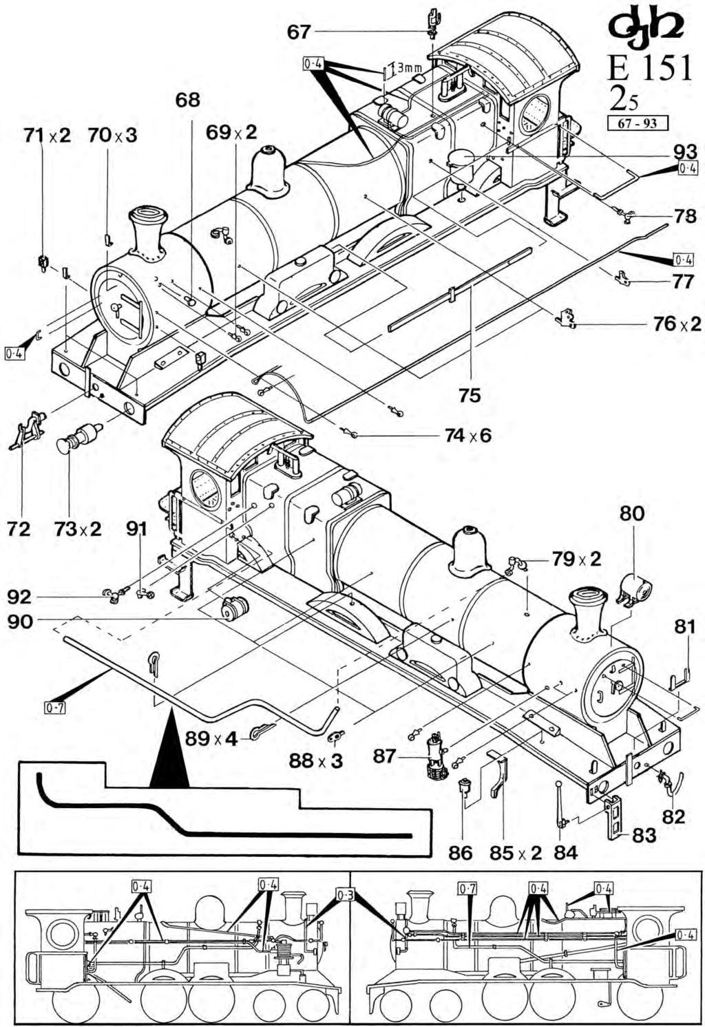
3 Fix the turned brass side frame mounts (T14x4) to the bogie side frames (T12x4). For good electrical pickup low melt solder is recommended here. The bogie stretchers (T11x2) are on the etched nickel silver valve gear fret -remove them and check that the holes either side fit over the brass side frame mounts (T14), you may need to enlarge the hole slightly. Check also that the holes for the screws (T16bx4) are large enough. Fold the stretchers as per drawing 1, using a pair of flat nosed (non-serrated) pliers. Push the brass wheel bearings (T13x8) in the bogie side frames using low melt solder if necessary, and attach the side frames to the stretcher with 0.4mm long brass screws (T16bx4)and washers (also from the nickel silver fret) (T16ax4). Tighten the screws then gently ease the side frames apart to fit the wheel sets (T15x4) in place, making sure the insulated wheels are on the same side for each bogie - see drawing 1. Trim the bogie mounting screws (T9ax2) to a length of 7.0mm and attach the assembled bogies to the tender using the springs (T9bx2) and washers (T9cx2). Tender Drawing T2 (Parts T21 - T34) If you have not already done so, fit water filler (T21 and tool box (T22). Fit drawbar pin (T23) using two M2 nuts (T24x2). Add fire irons (T25x3). Fit tender footplate (T26) followed by handbrake stand (T27) and handbrake handle (T28) - note, drill handbrake stand 0.8mm to accept the handbrake handle. Prior to fitting the ladder (T29) fold as per the insert drawing. Fit lamp bracket (T30), lamps (T31x2), buffers (T33x2) and brake pipe (T34). Locomotive Drawing 15 (Parts 35-66) As mentioned previously all holes shown on the drawing should be drilled prior to assembly. Trim the M2 screw (43) to a length of 12mm and secure in place inside the smoke box. Clean up the footplate (35) and remove any feed sprues from the centre cutout under the boiler. Fix the smoke box/boiler/firebox (42) assembly to the footplate (35) securing in place with M2 nut (44) making sure that the footplate is kept straight. Check that there is no flash inside the smoke box which may prevent the motor from fitting properly. Remove the cab (51) from the fret and fold as shown. Solder the inside corners of the sides/front. Fix the screw (52) into the cab as shown at this stage as it is not possible to do this once the cab assembly is completed. Take the fall plate (56) and fold the tabs down 90 degrees, then glue the plasticard (56a) to the underside trimming so that it overlaps the three outside faces by 0.8mm to prevent it shorting out against the tender. Attach to the cab floor (55) using 0.4mm wire as shown. Fold the cab support floor (54) as shown and fix into the cab. Fix the cab floor (55) on top of the cab floor support (54). Fit rear steps (39). Fold up edges of rear step treads (40x2) before fixing to rear steps (39). Fit buffer beam (41). Fit the completed cab to the footplate using M2 nut (53). The cab roof (57) should be fitted after the motor is fitted. Detail the boiler by adding the safety valves (50), steam generator (49), dome (48), chimney (47), smoke box door (45) and smoke box door handle. Fit front splashers (36x2), centre splashers (37x2) and rear splashers (38x2). The fitting of the gearbox (66), motor (60), motor tag (63), motor clip (64), flexible shaft (65), back head detail (59) and regulator handle (58) is covered under Chassis Drawing 7. Locomotive Drawing 25 (Parts 67-93) Drawing 4 shows the location of the locomotive body detailing parts 67 to 93. Note that the beam step (83) should be folded as shown before fitting. When fitting the guard irons (85x2) bend them out to the track centres before fitting (see photograph on the label for clarity). An insert drawing is provided as an aid in bending the clack valve piping. Note also that the boiler handrails go right around the boiler and that they have been shown broken on the drawing for clarity. Chassis Drawing 35 (Parts ) Take the chassis frames (92x2). Carefully clean out the axle holes with a 3.7mm drill bit and push fit the axle bushes (95x6). The bushes should be a firm fit in the frames, any loose bushes should be soldered in place. Note there are a number of holes on the chassis that may require cleaning out to a specific size, check drawing for details. Fit the turned brass chassis spacers (96a & 96b) noting that the rear spacer (96b) has a M2 thread for fixing the motor (see drawing) the hole in this spacer must be aligned vertically. Fit front mounting plate (98) and rear mounting plate (99) and tighten the spacer screws (97x4). Temporarily fit axles and wheels to the front and rear axles holes and place the chassis on a section of level track to check that the chassis sits properly on the track. If necessary, loosen the spacer screws and adjust. Remove the wheels and axles and solder the chassis together. Before fitting the driving wheels (102x3 and 103x3) note that the insulated wheels are on the L/H side as viewed from the top facing forward. Fit the driving wheels, axles (101x3) and axle washers (100x6) to the chassis with the axle nuts (103ax6), placing the axle gear (107a) on the first axle as shown on the drawing. If necessary clean out the hole in the axle gear with a 1/8" reamer or 1/8" drill bit. Move the gear to one side of the axle, place a small spot of superglue or Loctite 601 on the centre of the axle and push the gear to the centre of the axle. Make sure the gear is "square" with the axle. Be careful not to get any glue or Loctite in the axle bushes. Make sure that all axles rotate freely in the axle Page 3
4 bushes. The wheels are quartered so that the crank pin on the right hand wheel leads that of the left hand wheel by 90 degrees when the axle rotates forward. Use a Romford axle nut driver to tighten the axle nuts. Remove the etched counterweights (106x4), (107x2) from the fret and glue to the wheels as shown. Using a Romford axle nut driver fit the crankpins (105x6). Axle covers (104x6) should be fitted after final assembly and painting. Now fit drawbar/tender pickup placing Insulator (109) on M2 screw (108) cut to 10mm, and pass this through the rear mounting plate (99). Now add spring plate (110), loco tender coupler (111) and spring (112) as shown, followed by M2 nut (113.) Chassis Drawing 45 (Parts ) Fit crankpin spacer washers (114x6) then add rear coupling rods (115xpair) and front coupling rods (116xpair). For easy removal of the coupling rods during testing, painting etc, strip a short length of insulation from some fine electrical wire and push this "tubing" onto the crankpins as a temporary retainer. The crankpin washers (1 17x6) should not be fitted until the chassis has been completed and painted. Check that the rods revolve freely; should binding occur, locate where this happening and gently ease out the offending hole in the coupling rod with a rat-tail file, removing the minimum amount to achieve free movement. Sometime swapping the side rods around (i.e. left to right can overcome binding) Remove the wheels from the chassis. Using 1.0mm wire, fit the brakes (120x6). Fit brake stretchers (118x2), leading brake stretchers (119x2), pull rods (121x2). Fit brake link L/H (122) and brake link R/H (123) as shown -note the insert drawing shows the angle of part 123. Test fit slide bar support bracket (128) into the cutouts on top of the frame and put aside for later fitting. Make up cylinder assemblies using cylinder bodies (126x2), rear cylinder covers (125x2) and front cylinder covers (127x2) - note that rear cylinder covers are drilled 1.2mm. Fold the slide bars (124x2) as shown, note these are left and right handed, the etched fold line goes to the inside of the fold. Test fit the crosshead into slide bar, you may need to clear out the keyways of the crossheads using a knife-edge file, or you may need to lightly file the inside edges of the slidebars to achieve a good fit. Fit crankpin washers (130x2). Fix the slide bar assemblies to the rear of the cylinders and also attach underneath the cylinders - see drawing. Fix the completed cylinder assemblies to the frames. Chassis Drawing 55 (Parts ) Cut M2 screw (144) to 12.5mm and fit through the second hole on the front mounting plate (98) and secure in place with M2 nut (135). Short one wheel on each of the locomotive bogie axles (140x2) using 0.7mm wire. See insert in drawing. Fit the wheel inserts (142x4) to the wheels and assemble the bogie (138) using keeper plates (141x2) making sure that both shorted wheels are on the same side. Fit the bogie to the M2 screw (144) using washer (137), spring (136) and M2 nut (139) making sure that the shorted wheels are on the right hand side of the chassis. Fit wheels, axles and side rods. Fit the connecting rods (129xpair) to crossheads (131xpair) using 14BA screw (132x2) and nut (133x2). Fit crossheads into the slidebars and then fit the slide bar support bracket (128). Assemble the gearbox as per the accompanying instructions and trim the shaft to 6.Omm as shown in drawing 3. Do not force the worm onto the shaft. Carefully ream the worm bore using a 2.Omm drill or hand reamer so that the worm fits the shaft without undue force. Use a spot of superglue or Loctite 601 to permanently fix in place. Clean the shaft of excess glue or Loctite. As the gearbox screws are self tapping, screw the bottom cover plate screws in and out a couple of times before fitting the gearbox to the chassis. Trim the motor coupling sleeve (65) to 12mm and fit to the worm shaft of the gearbox - check that the ends of the worm shaft and motor shaft are free of sharp edges which could damage the tubing. Fit the gearbox onto the axle gear and secure in place with the gearbox keeper plate. Fit the locomotive body to the chassis securing with M2 nuts (134 and 143) Take two 60mm lengths of pickup wire and solder to the motor terminals and mark the positive (+) lead for later identification. Pass the motor through the hole in the front of the cab ensuring the motor coupling sleeve (65) couples to the shaft of the gearbox. Note, for easier fitting/removal of the motor, temporarily screw an M2 x 16mm bolt into one of the threaded holes in the rear of the motor, finger-tight only. Pass the wires down through the footplate, see drawing 3. Fit M2 screw (96c) to the rear chassis spacer (96b) and gently tighten the M2 screw just enough to retain the motor. Take the negative lead and solder it to the motor tag (63) which locates under M2 body mounting nut (143) (see drawing 7). The positive lead spot solders to loco tender coupling (111) (see drawing 5). Lightly oil the mechanism and test run, checking for electrical "shorts" on sharp curves etc. Also check that the motor does not overhead due to chassis binding. Page 4
5
6
7
8
9
10
11
12
13
NSWGR C30T LOCOMOTIVE AND TENDER KIT
 Australian Railway Kits ABN: 27 416 246 418 Incorporating Main West Models Manufacturers, Wholesalers and Retailers of Quality Australian Model Railways PO Box 252 Warwick, Queensland, 4370 Australia Phone/Fax:
NSWGR Z Tank Locomotive
 Australian Railway Kits ABN: 27 416 246 418 Incorporating Main West Models Manufacturers, Wholesalers and Retailers of Quality Australian Model Railways PO Box 252 Warwick, Queensland, 4370 Australia Phone/Fax:
4mm scale 009 gauge Lodge Hill & Upnor railway Chattenden Drewry loco body kit.
 RT Models 4mm scale 009 gauge Lodge Hill & Upnor railway Chattenden Drewry loco body kit. HISTORY The loco was supplied by the Drewry car co. to the Lodge Hill & Upnor Railway in 1949, works number 2263.
- 0 Gauge - Southern Railway Class 02 Chassis Construction & Parts Identification
 - 0 Gauge - Southern Railway Class 02 Chassis Construction & Parts Identification I would recommend constructing the body to the fitting of parts 42 before starting chassis construction. As the basic body
Bachmann GWR Earl (Dukedog) EM Finescale Conversion
 EM Finescale Conversion") Bachmann GWR Earl (Dukedog) EM Finescale Conversion Before you start, it is a good idea to have some small containers or snap top poly bags to put screws and components in for safe keeping...much better
Bachmann GWR Earl (Dukedog) EM Finescale Conversion Before you start, it is a good idea to have some small containers or snap top poly bags to put screws and components in for safe keeping...much better
Stephenson's Valve Gear: 7mm cast white-metal kit 19 th Century swing-link version - non-working, cosmetic only. Instructions
 SER-Kits Stephenson's Valve Gear: 7mm cast white-metal kit 19 th Century swing-link version - non-working, cosmetic only Page 1 of 5 Instructions HEALTH & SAFETY: The castings contain some lead. Dispose
BRL CLASS 66 LOCOMOTIVE. Building Instructions
 Tel 07807225801 prmrp@fsmail.net www.prmrp.com BRL - 066 CLASS 66 LOCOMOTIVE Building Instructions SCALE MODEL PRODUCT FOR ADULT MODELLERS ONLY. WHITE METAL CONTAINS LEAD WASH HANDS AFTER USE. MAY CONTAIN
Hornby Railroad Crosti 9F EM Finescale Conversion.
 Hornby Railroad Crosti 9F EM Finescale Conversion. Before you start, it is a good idea to have some small containers or snap top poly bags to put screws and components in for safe keeping...much better
INSTRUCTIONS FOR NYC K-11 PACIFIC KIT #100200
 INSTRUCTIONS FOR NYC K-11 PACIFIC 4-6-2 KIT #100200 These instructions provide photographs of completed model, exploded-view drawings, diagrams, step-by-step instructions and an itemized parts list. If
Hornby Railroad Hall EM Finescale Conversion.
 Hornby Railroad Hall EM Finescale Conversion. The subject of this sheet is the new (2015) Hornby Railroad Hall. There are several specification and livery variants, but all have a common chassis and as
1. Invert the tender, and hold in a suitable device. We use a foam cradle the Peco loco service cradle being ideal.
 Bachmann J11 EM Finescale Conversion Before you start, it is a good idea to have some small containers or snap top poly bags to put screws and components in for safe keeping...much better than crawling
RT Models. 4mm scale, 00/EM/P4 Manning Wardle, class K 0-6-0ST loco kit
 1 RT Models 4mm scale, 00/EM/P4 Manning Wardle, class K 0-6-0ST loco kit History The first of Manning Wardle s Class K was built in 1864. Many of these locos were mainly built for contractors with only
BRL-007 Detailing and Conversion Kit for NOVO/Triang Class 35 Hymek. Building Instructions
 Peter Besant Tel 07807225801 prmrp@fsmail.net www.prmrp.com BRL-007 Detailing and Conversion Kit for NOVO/Triang Class 35 Hymek Building Instructions SCALE MODEL PRODUCT FOR ADULT MODELLERS ONLY. WHITE
Heljan EM Finescale Conversion.
 Heljan 02 2-8-0 EM Finescale Conversion. Before you start, it is a good idea to have some small containers or snap top poly bags to put screws and components in for safe keeping...much better than crawling
Chopper Couplings. Assembly. Fitting
 Chopper Couplings Unlike most model chopper couplings, these will work with two opposing hooks, which looks so much better and allows you to turn stock at will. They are still compatible with most other
Mamod SL1K Locomotive Assembly Instructions
 Mamod SL1K Locomotive Assembly Instructions LOCOMOTIVE ASSEMBLY INSTRUCTIONS To ensure ease of construction reference to these instructions are essential. All the major parts are in the front of the box
Hornby GWR Star Class EM Finescale Conversion.
 Hornby GWR Star Class EM Finescale Conversion. Before you start, it is a good idea to have some small containers or snap top poly bags to put screws and components in for safe keeping...much better than
Finney7 BEYER PEACOCK BUILT LOCOMOTIVE
 BEYER PEACOCK BUILT LOCOMOTIVE Fig 1. Beyer, Peacock Built Locomotive Nos. 415-426 Depicted as built with short tanks, blower valve on the left, small dome, low tank front, 3 0 trailing wheels, snap head
The 2mm Scale Association etched replacement chassis for RTR loco bodies
 The 2mm Scale Association etched replacement chassis for RTR loco bodies Required Parts List Chassis etch (supplied) Motor - for all designs the Association can motor is suitable, alternatives are shown
Hornby 08 Diesel Shunter EM Finescale Conversion.
 Hornby 08 Diesel Shunter EM Finescale Conversion. Before you start, it is a good idea to have some small containers or snap top poly bags to put screws and components in for safe keeping...much better
Thank you for purchasing the Blackstone Models K-27!
 Operations Manual Thank you for purchasing the Blackstone Models K-27! Before your Mudhen whistles off, we want to tell you about a few things that will enhance your operating experience and ensure that
Bachmann D11 EM/S4 Finescale Conversion
 Bachmann D11 EM/S4 Finescale Conversion Before you start, it is a good idea to have some small containers or snap top poly bags to put screws and components in for safe keeping...much better than crawling
Dinorwic Quarry Hunslet `Alice Class with cab 7mm Scale kit for 16.5mm or 14mm Gauge
 EDM Models 19 Briar Avenue, Acomb, York. Y026 5BX Dinorwic Quarry Hunslet `Alice Class with cab 7mm Scale kit for 16.5mm or 14mm Gauge Introduction This kit, which has been researched by Jonathan Matthews
PYRTE. Building The Front Axle, Fork and Steering
 PYRTE Building The Front Axle, Fork and Steering The front axle on this traction engine is a very simple affair, in that it is a rectangular steel rod, sat on edge, with a pivot in the centre, which is
BRL-142/143 Class 142/143. Building Instructions
 Peter Besant Tel 07807225801 prmrp@fsmail.net www.prmrp.com BRL-142/143 Class 142/143 Building Instructions SCALE MODEL PRODUCT FOR ADULT MODELLERS ONLY. WHITE METAL CONTAINS LEAD WASH HANDS AFTER USE.
Victorian Railways X Class Locomotive and tender kit
 Victorian Railways X Class 2-8-2 Locomotive and tender kit Ref.E226A&B and E227, Manufactured by DJH exclusively for Steam Era Models Introduction The first X class Heavy Mikado, number 27, entered traffic
MANNING WARDLE ex-penrhyn Quarry Railway Narrow Gauge `Jubilee mm Scale kit for 16.5mm or 14mm Gauge
 EDM Models 19 Briar Avenue, Acomb, York. Y026 5BX MANNING WARDLE ex-penrhyn Quarry Railway Narrow Gauge 0-4-0 `Jubilee 1897 7mm Scale kit for 16.5mm or 14mm Gauge Introduction This kit, which was researched
ALAN GIBSON, THE BUNGALOW CHURCH ROAD, LINGWOOD, NORWICH, NORFOLK. MIDLAND/L.M.S. Class 4F.
 ALAN GIBSON, THE BUNGALOW CHURCH ROAD, LINGWOOD, NORWICH, NORFOLK MIDLAND/L.M.S. Class 4F. These instructions and history should be carefully studied BEFORE starting on any assembly. The standard kit is
FINNEY7. 24 Jul 18 A3-4 LNER A3. Fig 1. General Arrangement
 Fig 1. General Arrangement - 4 COUPLING RODS. The coupling rods are now made so that they can be used as a jig to align the hornguides accurately. First drill out all the crankpin holes to a convenient
FINNEY7. 24 Jul 18 4 LNER A4. Fig 1. A4 GA Drawing
 Fig 1. A4 GA Drawing 24 Jul 18 4 COUPLING RODS & FRAME PREPARATION Coupling rods. The coupling rods are made so that they can be used as a jig to align the horn blocks accurately. First drill out all the
MKD 08 BR 21.5 TON FLYASH HOPPER. Wagon Kit To cover Vacuum (CSV) and air braked types (CSA)
 and air braked types (CSA)") 1 MKD 08 BR 21.5 TON FLYASH HOPPER. Wagon Kit To cover Vacuum (CSV) and air braked types (CSA) History. Pulverised fuel ash (PFA), know as fly ash which is a by-product from the combustion process in coal
1 MKD 08 BR 21.5 TON FLYASH HOPPER. Wagon Kit To cover Vacuum (CSV) and air braked types (CSA) History. Pulverised fuel ash (PFA), know as fly ash which is a by-product from the combustion process in coal
Finney7 PC May17 PRINCESS CORONATION. Fig 1. GA Curved Footplate
 Fig 1. GA Curved Footplate PC - 5 Fig 2. GA Utility Footplate PC - 6 COUPLING RODS & FRAME ASSEMBLY COUPLING RODS. The coupling rods are now made so that they can be used as a jig to align the remaining
Wheels, paint and transfers required to complete. Please note that to aid the folding of the various parts score all the halfetched fold lines.
 Furness Railway Wagon Co. Furness Railway/LMS 45ton All Steel Bogie Iron Ore Hopper Wagon Built by The Pressed Steel Car Co. Pittsburgh, Pennsylvania, USA Circ. 1899 Wheels, paint and transfers required
(WW03f) BR PIPE WAGON 4 shoe brake
 BR PIPE WAGON 4 shoe brake") (WW03f) BR PIPE WAGON 4 shoe brake History. The pipe wagons were built to four basic diagrams sharing the same basic dimensions. The first 300 pipe wagons were built at Derby works to diagram 460, and
(WW03f) BR PIPE WAGON 4 shoe brake History. The pipe wagons were built to four basic diagrams sharing the same basic dimensions. The first 300 pipe wagons were built at Derby works to diagram 460, and
SEARAILS RR-XXX STEAM LOCOMOTIVES ASSEMBLY MANUAL
 SEARAILS RR-XXX 0-4-0 STEAM LOCOMOTIVES ASSEMBLY MANUAL 30 March 2015 T R Knapp Model Engineering 1 This diagram shows basic assembly of Nn3/Z Porter 0-4-0T 2 This diagram shows basic assembly of Baldwin
Walthers/Life-Like USRA Steam Locomotive
 North Raleigh Model Railroad Club Installing Decoders in N Scale Locomotives Detailed Instructions Walthers/Life-Like USRA 2-8-8-2 Steam Locomotive by David Derway May 17, 2010 Table of Contents Introduction...
Bowaters cab. Rear half of tropical cab frame. Cab door 82. Bend tags and solder to cab rear in open or closed position.
 Bowaters cab 29 32 44 31 Rear half of tropical cab frame 22 27 Cab door 82. Bend tags and solder to cab rear in open or closed position. 20 21 33 Side rod fitting and valve gear - Stephensons 44 0.7mm
Bachmann 1F (Half Cab) EM Finescale Conversion
 EM Finescale Conversion") Bachmann 1F (Half Cab) EM Finescale Conversion Before you start, it is a good idea to have some small containers or snap top poly bags to put screws and components in for safe keeping...much better than
Bachmann 1F (Half Cab) EM Finescale Conversion Before you start, it is a good idea to have some small containers or snap top poly bags to put screws and components in for safe keeping...much better than
$1.00 FOR THE TQIO/RCIO
 $1.00 FOR THE TQIO/RCIO m mm HDBBYSHOP Champion Jay Halsey has an impressive track record. One of Jay's advantages is a whisper smooth tranny thanks to his dad, Jim. Now you can build a Halsey transmission!
Gearbox Assembly 101. Introduction. Before Beginning. By Mark Schutzer 4/13/06
 Gearbox Assembly 101 By Mark Schutzer 4/13/06 Introduction If you are planning to re-motor an old brass locomotive you may want to upgrade to a new gearbox at the same time. The early 60 s and 70 s gearboxes
Owner s Manual: Standard Gauge Diesel shunter Locomotive in Gauge 3 scale. PLine. Built in Brass. Standard Gauge Shunter Locomotive Model (G3 scale)
") PLine Built in Brass Standard Gauge Shunter Locomotive Model (G3 scale) PLEASE READ THIS OWNERS MANUAL CAREFULLY BEFORE OPERATING THE MODEL Prototype Information: Not many Standard gauge locomotives operated
PLine Built in Brass Standard Gauge Shunter Locomotive Model (G3 scale) PLEASE READ THIS OWNERS MANUAL CAREFULLY BEFORE OPERATING THE MODEL Prototype Information: Not many Standard gauge locomotives operated
Motorising Set for Corgi Feltham Tram BEC-KITS) Fitting instructions
 Fitting instructions") Motorising Set for Corgi Feltham Tram The KW Trams (ex BEC-KITS) motorising set for the Corgi Feltham tram contains 2 motorised maximum traction bogies, with link wiring, and 2 bolsters. The following
Motorising Set for Corgi Feltham Tram The KW Trams (ex BEC-KITS) motorising set for the Corgi Feltham tram contains 2 motorised maximum traction bogies, with link wiring, and 2 bolsters. The following
Locomotive parts April 2018
 Locomotive parts April 2018 CONTENTS Page GNR Detail parts 3 LBSC Detail parts 4 GWR Detail parts 5 LMS Detail parts 10 LNER Detail parts 13 GER Details Parts 13 BR castings 14 Tooling & spares 15 2 GNR
Instructions: General American 6,000 Gallon, 3-Compartment Tank Car Kit 11/2013
 Instructions: General American 6,000 Gallon, 3-Compartment Tank Car Kit 11/2013 Thank you for purchasing the Tangent Scale Models General American 6,000 Gallon, 3- Compartment Tank Car Kit! A few quick
Micro-Trains #1021/#1022 Low short profile coupler
 1 Micro-Trains #1021/#1022 Low short profile coupler Low short profile coupler, for locomotives and cars with limited mounting area, makes 2 pair of either (1021) Life-Like E8A Pilot or Bachmann 4-8-4
Furness Railway Coach Co.
 Furness Railway Coach Co. Outside Framed Coaches Paint and transfers required to complete. Part 32 Part 7/8 Part 9 Part 6 Part 31 Part 14 The Parts. Part 19 Parts 20/21/22 Part 5 Part 4 Part 1 Part 3 Part
Instructions for Assembling Driving Wheels, Axles and Crankpins
 Instructions for Assembling Driving Wheels, Axles and Crankpins (Version 1; October 2008) Introduction These instructions explain how to assemble Exactoscale 4mm scale driving wheels, axles and crankpins
How to Replace the Main Axle Gear on the Bachmann Spectrum GScale using the NWSL # upgrade gear.
 How to Replace the Main Axle Gear on the Bachmann Spectrum GScale 4-4-0 and 2-6-0 Mogul (2001era), using the NWSL #2223-6 upgrade gear. By Paul M. Newitt (all text and photos Copyright Paul M. Newitt,
Application Note. Athearn RTR SW-1000/SW-1500 Tsunami Digital Sound Decoder Installation Notes
 Application Note Athearn RTR SW-1000/SW-1500 Tsunami Digital Sound Decoder Installation Notes Overview This application note describes how to install a TSU-AT1000 Digital Sound Decoder into the HO Athearn
Welcome Wagons WW ton Mineral (2 & 4 shoe brake)
") Welcome Wagons WW13 16 ton Mineral (2 & 4 shoe brake) HISTORY The 16T open mineral wagon was the most numerous type built by BR from 1950 to 1957, the first diagram being 108, although there was 16T steel
Welcome Wagons WW13 16 ton Mineral (2 & 4 shoe brake) HISTORY The 16T open mineral wagon was the most numerous type built by BR from 1950 to 1957, the first diagram being 108, although there was 16T steel
Installation Instructions Z-Gate Shifter
 Installation Instructions Z-Gate Shifter Part Number 80681 1998, 2001 by B&M Racing and Performance Products The B&M Z-Gate shifter can be used in vehicles equipped with most popular three speed automatic
Brassmasters Scale Models
 Brassmasters Scale Models www.brassmasters.co.uk Cleminson 6-wheel underframe kit PO Box 1137 Sutton Coldfield B76 1FU Copyright Brassmasters 2016 1 Introduction 1.1 The purpose of this booklet is to guide
Furness Railway Wagon Co. NER/LNER/BR C1 5ton Fitted Open Fish
 Furness Railway Wagon Co. NER/LNER/BR C1 5ton Fitted Open Fish Wheels, paint and transfers required to complete. Please note that to aid the folding of the various parts score all the halfetched foldlines
By Mark Schutzer NMRA National Convention, Sacramento, CA July 2011 Copies of this presentation can be found at
 Troubleshooting and dr Repairing i Brass Steam Locomotives By Mark Schutzer NMRA National Convention, Sacramento, CA July 2011 Copies of this presentation can be found at http://www.markschutzer.com Clinic
Bachmann Spectrum Peter Witt in HO
 Bachmann Spectrum Peter Witt in HO By Bob Dietrich This is my impression of an unpainted Peter Witt from Bachmann Spectrum. The packaging of the car was impressive a large red box with a clear cover showing
ACCUCRAFT TRAINS Central Avenue Union City, CA 94587, USA Tel: Fax:
 ACCUCRAFT TRAINS 33268 Central Avenue Union City, CA 94587, USA Tel: 510 324-3399 Fax: 510 324-3366 E-mail: info@accucraft.com www.accucraft.com General information About Accucraft Model: This accurately
Houstoun Gate Locomotive Works Gordon 4-Wheel Drive Chassis Assembly Instructions
 Houstoun Gate Locomotive Works Gordon 4-Wheel Drive Chassis Assembly Instructions It is suggested that you read these instructions through before commencing construction. A minimum of tools are needed
Application Note. Atlas RS-3 Tsunami Digital Sound Decoder Installation Notes
 Application Note Atlas RS-3 Tsunami Digital Sound Decoder Installation Notes Overview This application note describes how to install a TSU-AT1000 digital sound decoder into an HO Atlas RS-3. Skill Level
Installation Manual TWM Performance Short Shifter Cobalt SS/SC, SS/TC, HHR SS, Ion Redline and Saab 9-3
 Page 1 Installation Manual TWM Performance Short Shifter Cobalt SS/SC, SS/TC, HHR SS, Ion Redline and Saab 9-3 Please Note: It is preferable to park on a flat surface, as you will have to engage and disengage
Furness Railway Wagon Co.
 Furness Railway Wagon Co. The Parts. S&DJR/LMS/BR 20ton 6-Wheel Brake van Wheels, paint and transfers required to complete. Parts 13/15 Bolts/nuts/ washers Part 22 Part 5 Parts 10/19/20/21/ 23/24/25 Part
Lionel Class Era Steam: 384, 385, 390, 392, 400 Classic Steam Data Collection Form. Version 1.7
 Lionel Class Era Steam: 384, 385, 390, 392, 400 Classic Steam Data Collection Form. Version 1.7 1. Reporter names Date: December 26, 2012 6 pm 2. 384, 384E, 385E, 390, 390E 392E, 400E, 1760, 1770, 1770E
Brassmasters Scale Models
 Brassmasters Scale Models www.brassmasters.co.uk L&SWR/SOUTHERN RAILWAY DRUMMOND M7 0-4-4T LOCOMOTIVE KIT Designed by Martin Finney 4MM SCALE OO - EM - P4 INSTRUCTIONS AND PROTOTYPE NOTES PO Box 1137 Sutton
INSTRUCTIONS FOR ORENSTEIN & KOPPEL RL1C 4WDM LOCOMOTIVE 7MM SCALE 1:43.5 FOR 16.5MM OR 14MM GAUGE
 NONNEMINSTRE MODELS INSTRUCTIONS FOR ORENSTEIN & KOPPEL RL1C 4WDM LOCOMOTIVE 7MM SCALE 1:43.5 FOR 16.5MM OR 14MM GAUGE BACKGROUND & HISTORICAL This product of the well-known German manufacturer Orenstein
Tip: and Orient Express LED Light Upgrade Date: Correction
 Hi All, I have since inherited my friend Rudolf s 42755 Orient Express with the extra 42760 car set and wanted to complete the LED light upgrade as we had planned. Side view of the Restaurant car with
CUMBRIAN RAILWAYS ASSOCIATION MODELLING CUMBRIAN RAILWAYS KITS AND ACCESSORIES 1
 Bill Bedford models http://www.mousa.uk.com/index.html CUMBRIAN RAILWAYS ASSOCIATION KITS AND ACCESSORIES 1 Furness Railway 10mm BCK1841 D.21 BCl 288.25 172.95 BCK1842 D.22 Cl 288.25 172.95 BUK220 47ft
PARTS IDENTIFICATION AND ASSEMBLY INSTRUCTIONS
 The U.S. M10 ammunition trailer was used mostly by armored units to transport additional ammunition. It could be towed by many different vehicles, including 2 ½ ton trucks, half tracks, armored cars, self-propelled
HO Scale AC-12 Gear Box Replacement Instructions
 HO Scale AC-12 Gear Box Replacement Instructions Introduction Thank you for your purchase of the HO Scale AC-12 from InterMountain Railway Company. The enclosed gear box kit will increase the speed of
Caley Coaches True Line kits in etched brass
 Caley Coaches True Line kits in etched brass 0141-772 37 Jim Smellie, 1 Tay Crescent, Bishopbriggs, Glasgow, G64 1EU. Jim Smellie Nov. 1992 10' Building Instructions for kit CC20 Caledonian Railway 1 Ton
Instructions: Pullman-Standard PS-3 Coal Hopper Kit Tangent Part Numbers: through /2015
 Instructions: Pullman-Standard PS-3 Coal Hopper Kit Tangent Part Numbers: 15000-01 through 15001-01 10/2015 Thank you for purchasing the Tangent Scale Models Pullman-Standard PS-3 Coal Hopper Kit! A few
PRO RATCHET UNIVERSAL SHIFTER
 Installation Instructions PRO RATCHET UNIVERSAL SHIFTER Fits: GM, Ford and Chryslers w/automatic Transmission See Application Guide for Specific Vehicles Catalog # 80842 WORK SAFELY! For maximum safety,
Solar Trike w i t h A C C U b a t t e r y d r i v e a n d LED lighting
 1.693 Solar Trike w i t h A C C U b a t t e r y d r i v e a n d LED lighting Necessary materials Fretsaw with metalworking blade drills. dia. 3,, 6, 7, Machine vice with soft jaws Soldering iron, solder
Accucraft Decauville 3.5t Type 1 1:13.7
 Accucraft Decauville 3.5t Type 1 1:13.7 B77-531 7/8ths Type 1 Maroon B77-532 7/8ths Type 1 Green B77-533 7/8ths Type 1 Black Instruction Manual for Decauville Type 1 Note: Please read the entire manual
Z-Gate Universal Shifter
 Installation Instructions Z-Gate Universal Shifter Fits: GM, Ford, Lincoln and Chrysler Transmissions See Application Guide for Specific Applications Part #80681 Rev 06/01/2018 WORK SAFELY! For maximum
Instructions: PRR Sam Rea Shops X58 Class Box Car Kit Tangent Part Numbers: XX through XX 9/2015
 Instructions: PRR Sam Rea Shops X58 Class Box Car Kit Tangent Part Numbers: 14000-XX through 14002-XX 9/2015 Thank you for purchasing the Tangent Scale Models PRR Sam Rea Shops X58 Class Box Car Kit! A
Bachmann. Climax. Phoenix Sound Systems, Inc West Liberty Road Ann Arbor MI
 Bachmann Climax Phoenix Sound Systems, Inc. 3514 West Liberty Road Ann Arbor MI 48103 www.phoenixsound.com phone: 800-651-2444 fax: 734-662-0809 e-mail: phoenixsound@phoenixsound.com 2004-2007 Phoenix
Tip: Difficult Conversions for F800 (3026) and 3111 Date: Led lighting added, LED Addition 3111
 and 3111 Date: Led lighting added, LED Addition 3111") Hi All, It s good to revisit previous conversions and see if you can improve on what has been done before. I decided to add LED lighting to my F800 (3026) and 3111. This document update shows how it was
Hi All, It s good to revisit previous conversions and see if you can improve on what has been done before. I decided to add LED lighting to my F800 (3026) and 3111. This document update shows how it was
Furness Railway Wagon Co.
 Furness Railway Wagon Co. The Parts. S&DJR/LMS/BR 10ton 4-Wheel Brake van Wheels, paint and transfers required to complete. Part 3 Part 2a Part 2b Part 5 Parts 8/9/10 Part 15 Part 15 Part 6 Part 4 Part
SUBARU FORESTER - SIDE STEP DIESEL VERSION INSTALLATION INSTRUCTIONS
 SUU FORESTER - SIDE STEP DIESEL VERSION INSTALLATION INSTRUCTIONS SS00 VEHICLE DESCRIPTION: PART NUMBER: SUU FORESTER SACC00 R 9 L 0 Care Instructions: Clean Side Steps with a mild detergent and water
HOT-AIR ENGINE. Page 1
 Page 1 The pretty little toy about to be described is interesting as a practical application to power-producing purposes of the force exerted by expanding air. It is easy to make, and, for mere demonstration
Furness Railway Wagon Co. NER/LNER/BR Cattle Van
 NER/LNER/BR Medium Cattle Van Wheels, paint and transfers required to complete. Part 1 The Parts. Part 4 Part 3 Part 2 Part 17 Part 5 Part 12/16 Part 11 Part 13/14/15 Part 6/7 Parts 8/9/10 not shown Assembly
Troubleshooting and Repairing Brass Steam Locomotives
 Troubleshooting and Repairing Brass Steam Locomotives By Mark Schutzer PCR Regional Convention, Concord, CA May 2005 Copies of this presentation can be found at http://www.markschutzer.com Clinic Overviews
Kato P42 Tsunami Digital Sound Decoder Installation Notes
 Kato P42 Tsunami Digital Sound Decoder Installation Notes Overview This application note describes the procedure for installing a TSU-KT1000 Digital Sound Decoder into a Kato HO P42 locomotive. Skill Level
J & D Machine / Hyperdrive / MSA 3711 Moon Bend Rd. Chapel Hill, TN 37034
 J & D Machine / Hyperdrive / MSA 3711 Moon Bend Rd. Chapel Hill, TN 37034 www.hyperdriveracing.com 1 You now own a state of the art 1/10 scale oval race car. The Hyperdrive Assault has gone through months
Furness Railway Wagon Co.
 Furness Railway Wagon Co. Great Eastern Railway/LNER/BR 1900 Diagram 7 10ton Cattle Van Steel Under-Frame Wheels, paint and transfers required to complete. Please note that to aid the folding of the various
Fabric Replacement Top Installation Instructions
 Fabric Replacement Top Installation Instructions For: GEO Tracker, Suzuki Sidekick & Vitara 1986-1994 Parts List Top, Soft (1) Rear Window (1) WARNING This product is designed to enhance the appearance
This year Märklin have released a coach which has included LED lighting with a currentconducting close coupler (single pole)
") Hi All, Over the past few months I have been working at a steady pace to install LED lighting in my passenger coaches. The coach lighting must have LED lights to reduce power consumption on the layout
Hi All, Over the past few months I have been working at a steady pace to install LED lighting in my passenger coaches. The coach lighting must have LED lights to reduce power consumption on the layout
WARNING. When installed in accordance with these instructions, the front protection bar does not affect operation of the SRS airbag.
 Part Number: 343870 F/Kit 17557 Product Deluxe Combination Winch and Non Winch Bull Bar Description: Suited to Nissan XTERRA 05ON USA Only vehicle/s: WARNING REGARDING VEHICLES EQUIPPED WITH SRS AIRBAG;
Deuce/Ace Installation Instructions
 HARDWARE KIT: Upper Mounting Plate: 2-7/16" (11mm) X 3.5" bolts 2-7/16" flange nuts 2-2" spacers 2-7/16" trim cap mounting washers 2 - plastic trim caps TOOLS NEEDED: safety glasses wrenches 16mm or 5/8"
Light Truck MegaShifter
 Installation Instructions Light Truck MegaShifter The B&M Light Truck Megashifter shifter is designed to be used in most light trucks equipped with most popular three speed or four speed automatic transmissions.
Tesla Model S Rear Lighted T
 Tesla Model S Rear Lighted T Installation Instructions The rear lighted T makes your Tesla Model S distinctive if not unique from other cars on the road and other Model S s. This LED powered device is
SMITHS CAR CLOCK REPAIR KIT
 SMITHS CAR CLOCK REPAIR KIT Version 9 1 Introduction These instructions explain how to repair a Smith s electric car clock mechanism using the Clocks4Classics repair kit. This kit uses a specially developed
Upgrading Proto axle Geeps with Stewart Trucks. November 27, 2010 Mark Schutzer
 Upgrading Proto 2000 4 axle Geeps with Stewart Trucks November 27, 2010 Mark Schutzer Introduction Several years ago Proto 2000 made a bunch of 4 axle locomotives that used trucks that were a copy of an
Tip: Water Crane with Servo Motor, LED Lantern, Moving Man Date: Update includes video
 Hi All, I ve had the Faller Swivel Water Spouts kit 120137 (B137 = old number) since 2000, which I will refer to as a Water Crane. I assembled the kit at the time with the intent of animating it with a
WW03e Welcome Wagons 8 Shoe Brake Pipe Wagon
 WW03e Welcome Wagons 8 Shoe Brake Pipe Wagon History The pipe wagons were built to four basic diagrams sharing the same basic dimensions. The first 300 pipe wagons were built at Derby works to diagram
Build your own THUNDERBIRD 2
 PACK 01 STAGE PAGE 01 Nose assembly and Elevator Car rear wheels 3 02 Cockpit interior and Elevator Car 1 completion 7 03 Missile launcher and Thunderbird 4 11 04 Nose assembly and the Tracy brothers 15
Installation Instructions. QuickSilver Shifter. Fits: GM, Ford, Chrysler Transmissions See Application Guide for Specific Applications Part # 80683
 Installation Instructions QuickSilver Shifter Fits: GM, Ford, Chrysler Transmissions See Application Guide for Specific Applications Part # 80683 WORK SAFELY! For maximum safety, perform this installation
MYLOCOSOUND LARGE SCALE DIESEL LOCOMOTIVE KIT
 1 MYLOCOSOUND LARGE SCALE DIESEL LOCOMOTIVE KIT 1.OVERVIEW 16mm to the foot scale model of an 0-4-0 Sugar Cane locomotive. Easy glued assembly. Heavy, high quality motor, gears and steel chassis for a
Right On Replicas, LLC Step-by-Step Review * Mack Fire Pumper 1:32 Scale Revell Model Kit # Review
 Right On Replicas, LLC Step-by-Step Review 20150915* Mack Fire Pumper 1:32 Scale Revell Model Kit #85-1945 Review The Mack CF600 Pumper is a familiar fire truck that is still widely used in firehouses
Troubleshooting and Repairing Brass Steam Locomotives
 Troubleshooting and Repairing Brass Steam Locomotives By Mark Schutzer PCR Regional Convention, Santa Cruz, CA May 2007 Copies of this presentation can be found at http://www.markschutzer.com Clinic Overviews
C15C C15C. Page 1 of 20
 2 x Lid Front Hinge 1135 8 x M8 Bolt 8 x M8 Washer (3mm Thick) 4 x M6 Large washers 4 x M6 Spring washers 4 x M6 x 40mm Bolts 6 x M6 20mm Bolts 6 x M6 Washers 20 x Screws 2 x Lid mount gas strut bracket