Application Note. Atlas RS-3 Tsunami Digital Sound Decoder Installation Notes
|
|
|
- Marsha Rogers
- 5 years ago
- Views:
Transcription


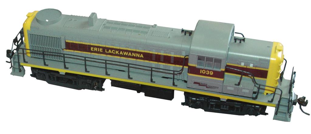
1 Application Note Atlas RS-3 Tsunami Digital Sound Decoder Installation Notes Overview This application note describes how to install a TSU-AT1000 digital sound decoder into an HO Atlas RS-3. Skill Level 4: The entire installation can be completed with a couple of hours and some mechanical modifications. Bill of Materials Stock No. Description TSU-AT1000 for the ALCO 244 Small Oval Speaker Two 1.3mm Microbulbs Heat Shrink Tubing Kit Evergreen P.N Sheet Styrene For your convenience, Evergreen part numbers have been listed above. Please visit their web site at Tools You Will Need 25W Soldering Iron With Fine Tip Rosin Core Solder Miniature Screwdriver Set X-acto Knife Wire Cutters Wire Strippers Metal Hacksaw Metal File Miniature Razor Saw Heat Gun/Hair Dryer Clear Silicone/Aquarium Sealant Liquid Plastic Cement Masking Tape Black Paint 28 Gauge Wire (Gray and Orange Preferred) Dremel Rotary Tool (or similar) with Cut-Off Wheel


2 Installation Remove the body shell as seen in Photo 1. The tabs that hold the shell on are located near the corners of the body shell. Gently squeeze at these locations and the shell should lift off the frame. Once removed, you should see the factory light board mounted on top of the motor. (Photo 1) After the weights are removed you will see two light pipes in the shell that need to be removed as well. These are press-fit into the headlamp casting and can be pulled out carefully with a pair of pliers. (Photo 3) Photo 3 Photo Located inside the shell are two heavy lead weights. These are press-fit into the shell. Using a pair of pliers gently grab and remove these weights. (Photo 2) Photo 2 On this model we used 1.5V microbulbs, but LEDs can be easily substituted. (See the Tsunami Installation Guide for help installing LEDs.) Cut the end of the pipes off about 1/2 near the headlamp casting side using a dremel tool or saw. (Photo 4) Photo 4 5. Now, using a dremel tool or a saw blade carefully cut out a 1/4 U shaped recession into the shorter pieces of the light pipes. (Photo 5) Photo 5
 terminal of the battery and the other lead to the negative(-) terminal. The bulb should turn on.")

 8. Photo 6 9.")
 Photo 10 14. Glue the windows back into the cab with plastic cement (such as Tenax 7R.")

3 12. Remove the window glazing carefully by gently prying it out of the window casting using a flat head screwdriver. (Photo 9) 6. Test that the microbulbs work. Using a 1.5V battery touch one microbulb lead to the plus(+) terminal of the battery and the other lead to the negative(-) terminal. The bulb should turn on. Follow this procedure for both bulbs. 7. Slide a 1/2 piece of 1/16 shrink tubing over the microbulb and slide up to the base of the bulb. Shrink the tubing with your heat gun or alternate heat source. This will act as a grip for the larger piece of tubing that will seal the bulb into the light pipe. Photo 9 Next fit the bulb into the U shaped cut you made in the light pipe allowing the shrink tubing to protrude from the end. (Photo 6) 13. Carefully separate the sides of the windows by cutting away the center support with wire cutters or a miniature razor saw. (Photo 10) 8. Photo 6 9. Slide a 1/2 piece of 3/8 tubing over the microbulb so that it rests with one end over the section of smaller tubing and the other end covering the microbulb and cut portion of the light pipe. Shrink the tubing. (Photo 7) Photo Glue the windows back into the cab with plastic cement (such as Tenax 7R.) These need to be glued in place because the tabs that hold the cab in place are cast into them. Set the cab aside to dry. (Photo 11) Photo Follow steps 6-9 for the second light assembly and then set both aside for now. 11. Next, remove the cab from the body shell. There are four tabs that hold the cab in place under the center windows. Press these toward the center of the cab to release the cab from the body. (Photo 8) Photo 11 Photo 8


4 15. For the speaker to fit, a small amount will need to be trimmed off the ends. Cut this away using the cut-off wheel on the dremel tool or a small saw. Caution: Do not to cut into the cone. Cutting the speaker cone will damage the speaker and cause poor sound quality. (Photo 12) Photo Test fit the speaker into the cab to ensure that it fits. Start by routing the wires through the small notches that remain after cutting the speaker to size. Then gently press down on the sides of the speaker, taking care not to damage the cone, so it slides into the roof line of the cab. It should fit just above the side windows of the cab to allow the addition of an interior if desired. (Photo 13 and 14) 17. The cab is a bit wider than the speaker. The extra space can be filled with a styrene strip shown in Photo 14. Paint the styrene black to help disguise the speaker so that it will be harder to see through the windows. This will be cemented into place to seal the speaker baffle, which is created by the roof of the cab. Use aquarium sealant to help seal any open areas including the open notches on the speaker. Take care not to get any of the silicone on the cone of the speaker. Set the cab aside to fully cure and dry. 18. Remove the upper portion of the body shell that fits inside the cab. Be careful not to remove too much or the tabs from the cab windows will not fit correctly. Remove the material on the top half of the shell as shown to allow the cab to fit and cover the new shell opening. Clean up the cut edges with a small file. (Photo 15 and 16) Cut Here Photo 15 Photo Cement the light assemblies from Step 10 into the front and rear of the shell as shown using the aquarium sealant. Set these aside to fully dry. (Photo 17) Photo 17 Photo 13 Photo Photo 18 shows an older Atlas/Kato light board; more recent models may contain a similar, but different color PCB. We will be removing this light board and replacing it with our SoundTraxx decoder. (Photo 18) Photo 18
 22. Remove the board by releasing the two tabs toward each end of the motor. The board will lift off at this point.")
 Photo 20 27. Now, install the SoundTraxx decoder into the model.")

5 21. Clip the wires attached to the factory board as close to their solder connections on the board as possible. It s a good idea to label the wires with masking tape. 26. Repeat this process with the M- strip and a similar piece of gray wire. (Photo 20) 22. Remove the board by releasing the two tabs toward each end of the motor. The board will lift off at this point. 23. Next, gently clip the motor leads loose. On some models, like the one shown in Photo 19, copper strips serve as the motor leads, while in others the motor leads are simple wires. If your model has wires for the motor leads, label the positive and negative lead wires with tape and then skip to Step 26. (Photo 19) Photo Now, install the SoundTraxx decoder into the model. Use the same two tabs to hold the Tsunami decoder in place that were used to hold the factory light board in place. Then solder the track pick-up wires to the decoder. Be sure to note which wire goes to which side to avoid any short circuits. For help refer to the wiring diagram at the end of this document. 28. Attach the orange wire to Terminal 5 (the M+ tab) and the gray wire to Terminal 6 (the M- tab). (Photo 21) Photo If the motor leads consist of copper strips, as shown in Photo 19, you ll need to replace them with wires. The copper strip that sits above the motor is Motor Plus (+). The Motor Minus (-) strip goes to the underside of the motor. Start by cutting both strips short, leaving just enough length to still be able to solder wires to them. 25. Solder a 2-3 piece of orange wire to the M+ copper strip. Slide a piece of 1/8 shrink tubing over the wire and cover the joint between the strip and the wire. Ideally, your shrink tubing will be cut long enough to cover most of the copper strip, helping to prevent any inadvertent short circuits. Shrink with your heat gun. Photo Test run the model now to ensure there are no crossed wires or short circuits, and that the locomotive is running in the correct direction. This can be done by placing the locomotive on your main line and running it in both directions. There will be no sound or lights yet, but the motor should respond properly. There is a red LED on the Tsunami decoder that will indicate that the power is being applied correctly and a second red LED will go on and off with the headlight commands.


 Short Hood Weight Long Hood Weight Photo 23 32. Discard the small pieces.")

6 30. Once proper operation is verified, we ll need to modify the two weights to allow space for the Keep-Alive Capacitor. (Photo 22) Cut Here Cut Here 33. Now, attach the cab to the shell. First run the speaker wires through the opening for the cab and snap the cab into place. Following the wiring diagram at the end of this document, wire the lights and the speaker to the decoder. (Photo 25) Bevel Short Hood Weight Long Hood Weight Photo Cut the tip off the short hood weight using a hacksaw, then file to clean the edges. (Photo 22) To allow room for the keep-alive capacitor, we cut straight down at the end of the bevel on the long hood weight. Clean up any rough or sharp edges using a file. (Photo 23) Short Hood Weight Long Hood Weight Photo Discard the small pieces. Take the two remaining weights and press them into the body shell with the smaller of the two weights on the long hood side. (Photo 24) Photo 24 Photo Test the installation to be sure that everything functions properly by placing the locomotive on the main and running it in both directions, testing the lights, and playing the horns. If everything is working as it should, tuck the wires into the shell and replace the shell on the body. Test again to ensure that no wires are caught in the drive train or causing vibration noise. Taping the wires out of the way will eliminate this problem. All that is left at this point is to program the decoder and enjoy running!
7 Wiring Diagram TM New Dimensions in Digital Sound Technology 2010 Throttle Up! Corp. All Rights Reserved 141 Burnett Drive Durango, CO Phone: (970) Toll Free: Fax: (970) Website:
Atlas Silver Series HO RS-3 (2014 Release) Tsunami Digital Sound Decoder Installation Notes
 Tsunami Digital Sound Decoder Installation Notes") Atlas Silver Series HO RS-3 (2014 Release) Tsunami Digital Sound Decoder Installation Notes Overview This application note describes how to install a TSU-AT1000 Digital Sound Decoder into an Atlas Silver
Atlas Silver Series HO RS-3 (2014 Release) Tsunami Digital Sound Decoder Installation Notes Overview This application note describes how to install a TSU-AT1000 Digital Sound Decoder into an Atlas Silver
Atlas HO MP-15 Tsunami Digital Sound Decoder Installation Notes
 Atlas HO MP-15 Tsunami Digital Sound Decoder Installation Notes Overview This application note describes how to install a TSU-AT1000 digital sound decoder into an Atlas HO MP-15. Skill Level 2: The entire
Application Note. Athearn RTR SW-1000/SW-1500 Tsunami Digital Sound Decoder Installation Notes
 Application Note Athearn RTR SW-1000/SW-1500 Tsunami Digital Sound Decoder Installation Notes Overview This application note describes how to install a TSU-AT1000 Digital Sound Decoder into the HO Athearn
Athearn SD40 Tsunami Digital Sound Decoder Installation Notes
 Athearn SD40 Tsunami Digital Sound Decoder Installation Notes Overview This application note describes how to install a TSU-AT1000 into an Athearn Ready-To-Roll HO SD40. Skill Level 2: The entire installation
Athearn SD40T-2 Tsunami Digital Sound Decoder Installation Notes
 Athearn SD40T-2 Tsunami Digital Sound Decoder Installation Notes Overview This application note describes how to install a TSU-AT1000 into an Athearn Ready-To-Roll HO SD40T-2. Skill Level 2: The entire
Broadway Limited (and Blueline) SD40-2 Tsunami Digital Sound Decoder Installation Notes
 SD40-2 Tsunami Digital Sound Decoder Installation Notes") Broadway Limited (and Blueline) SD40-2 Tsunami Digital Sound Decoder Installation Notes Overview This application note describes how to install a TSU-AT1000 digital sound decoder into a HO Broadway Limited
Broadway Limited (and Blueline) SD40-2 Tsunami Digital Sound Decoder Installation Notes Overview This application note describes how to install a TSU-AT1000 digital sound decoder into a HO Broadway Limited
Athearn RTR EMD CF7 Tsunami Digital Sound Decoder Installation Notes
 Athearn RTR EMD CF7 Tsunami Digital Sound Decoder Installation Notes Overview This application note describes how to install a TSU-AT1000 into an Athearn HO Ready-To-Roll EMD CF7. Skill Level 2: The entire
Application Note. Bachmann F40PH Tsunami Digital Sound Decoder Installation Notes
 Application Note Bachmann F40PH Tsunami Digital Sound Decoder Installation Notes Overview This application note describes how to install a TSU-AT1000 Digital Sound Decoder into a Bachmann HO F40PH. Skill
Athearn Genesis GP38-2 Tsunami Digital Sound Decoder Installation Notes
 Athearn Genesis GP38-2 Tsunami Digital Sound Decoder Installation Notes Overview This application note describes how to install a TSU-GN1000 digital sound decoder into an Athearn Genesis HO GP38-2. Skill
Athearn RTR EMD GP35 Tsunami Digital Sound Decoder Installation Notes
 Athearn RTR EMD GP35 Tsunami Digital Sound Decoder Installation Notes Overview This application note describes how to install a TSU-AT1000 into an Athearn HO Ready-To-Roll EMD GP35. Skill Level 2: The
Athearn RTR F59PHI Tsunami Digital Sound Decoder Installation Notes
 Athearn RTR F59PHI Tsunami Digital Sound Decoder Installation Notes Overview This application note describes how to install a TSU-GN1000 Digital Sound Decoder into an Athearn HO Ready to Roll EMD F59PHI
Application Note. Athearn Genesis SD70MAC Tsunami Digital Sound Decoder Installation Notes
 Application Note Athearn Genesis SD70MAC Tsunami Digital Sound Decoder Installation Notes Overview This application note describes how to install a TSU-GN1000 digital sound decoder into an Athearn Genesis
Kato P42 Tsunami Digital Sound Decoder Installation Notes
 Kato P42 Tsunami Digital Sound Decoder Installation Notes Overview This application note describes the procedure for installing a TSU-KT1000 Digital Sound Decoder into a Kato HO P42 locomotive. Skill Level
Application Note. KATO SD40-2 Mid Tsunami Digital Sound Decoder Installation Notes
 Application Note Overview This application note describes how to install a Tsunami TSU-KT1000 Digital Sound Decoder into the HO Kato SD40-2 (Mid-production). Skill Level 2: The entire installation can
Application Note. Walthers/Proto 2000 E7A Tsunami Digital Sound Decoder Installation Notes
 Application Note Overview This application note describes how to install a TSU-1000 digital sound decoder into a Walthers/ Proto 2000 E7A. Skill Level 2: The entire installation can be completed in one
Bachmann Digital Sound Decoder Installation Notes
 New Dimensions in Digital Sound Technology TM APPLICATION NOTE Bachmann 2-6-6-2 Digital Sound Decoder Installation Notes Overview This application note describes the installation of a DSD-090LC Digital
Athearn Pacific Digital Sound Decoder Installation Notes
 New Dimensions in Digital Sound Technology TM APPLICATION NOTE Overview This application note describes how to install a DSD-100LC Digital Sound Decoder into the Athearn Pacific Locomotive. All of the
WifiTrax WMR-10 in Atlas RS-3
 WifiTrax WMR-10 in Atlas RS-3 How to Install the WifiTrax WMR -10 Board Replacement Wi-Fi Controller in Atlas RS-3 Locomotive Practical notes by Steve Shrimpton Back to Web Site In my opinion the Alco
Walthers/Life-Like USRA Steam Locomotive
 North Raleigh Model Railroad Club Installing Decoders in N Scale Locomotives Detailed Instructions Walthers/Life-Like USRA 2-8-8-2 Steam Locomotive by David Derway May 17, 2010 Table of Contents Introduction...
Signal Mirror Installation Instructions
 Signal Mirror Installation Instructions Ford F-250 to F-750 Pick-Up, Super-Duty 1998-2007 Trailer Tow Mirror Ford Excursion XLT/Limited 2000-2002 Trailer Tow Mirror Ford Excursion (all models) 2003-2005
THE MOTOR. Page 1 of 9
 Page 1 of 9 The Bachmann HO Old Time 4-4-0 has been around a long time and suffers from two problems: the latest motor will burnout with a frying of the added DCC decoder and the pickup system is very
By Mark Schutzer PCR Regional Convention, San Luis Obispo May 2014 Copies of this presentation can be found at
 A Beginners Guide to Installing DCC Decoders By Mark Schutzer PCR Regional Convention, San Luis Obispo May 2014 Copies of this presentation can be found at http://www.markschutzer.com Clinic Overview Installing
These instructions show how to build the Remote Controlled Fart machine Sound Kit.
 Remote Controlled Fart Machine Assembly Instructions These instructions show how to build the Remote Controlled Fart machine Sound Kit. Tools Required Drill with 7/64, 3/16, and ¼ drill bits. Holt melt
Gauge Wiring Instructions
 Thank you for purchasing the Track Dog Racing Gauges. These instructions are for wiring the Westach brand gauges with the TDR gauge panel for all model years of the Miata. Refer to the installation instructions
INSTALLATION INSTRUCTIONS
 Rear Vision System Liftgate Emblem Camera Mirror Display 2009-2012 Ford Flex (Kit part number 1008-9527) Kit Contents: Mirror Liftgate Emblem Mount with Camera Interior (shorter) Harness Chassis (longer)
INSTALLATION INSTRUCTIONS
 Rear Vision System Tailgate Emblem Camera Mirror Display 2009-Current Ford F-150 and 2010-Current Super Duty (Kit part number 1008-9527) Kit Contents: Mirror Tailgate Emblem Mount with Camera Interior
#TL T EA888 GEN 3 FUELING SYSTEM/ INSTALLATION INSTRUCTIONS
 #TL100069 2.0T EA888 GEN 3 FUELING SYSTEM/ INSTALLATION INSTRUCTIONS Notes: These instructions were written for a North American specification MkVII GTI. Other models, like the Golf R, are similar. When
Tip: and Orient Express LED Light Upgrade Date: Correction
 Hi All, I have since inherited my friend Rudolf s 42755 Orient Express with the extra 42760 car set and wanted to complete the LED light upgrade as we had planned. Side view of the Restaurant car with
Operation and Installation Manual
 Operation and Installation Manual G-Scale Graphics 5860 Crooked Stick Dr. Windsor, CO 80550 970-581-3567 GScaleGraphics@comcast.net www.gscalegraphics.net Revision A: Updated 2/7/2018 Page Overview The
Four Panel Amber LED Front Light Kit Installation Guide
 Four Panel Amber LED Front Light Kit Installation Guide Kit Contents: 2 LED panels 4 socket plugs 1 cut out template PN 2100886 Please refer to webiste for full warranty information. DIGI-TAILS is not
WOC & WOC Top & Back Installation Instructions
 Shown with optional Sun Roof WOC-900500-2 & WOC-900501-2 Top & Back Installation Instructions Install Order! Heater Door System Wiper on to Windshield Windshield Rear Panel Top Panel Tools needed: 5/16
LGT-306L / LB Club Car Precedent LED Light Bar Bumper Kit Installation Instructions
 LGT-306L / LB Club Car Precedent LED Light Bar Bumper Kit Installation Instructions Caution: Please read through the instructions carefully. Before starting this project, remove the system s positive and
M GT 2005 up Mustang ENGINE START Push-Button INSTRUCTION SHEET
 Please contact the Ford Racing Techline for the most current instruction information @ (800) FORD-788!!! PLEASE READ THE FOLLOWING INSTRUCTIONS CAREFULLY PRIOR TO INSTALLATION!!! OVERVIEW: The following
This year Märklin have released a coach which has included LED lighting with a currentconducting close coupler (single pole)
") Hi All, Over the past few months I have been working at a steady pace to install LED lighting in my passenger coaches. The coach lighting must have LED lights to reduce power consumption on the layout
Hi All, Over the past few months I have been working at a steady pace to install LED lighting in my passenger coaches. The coach lighting must have LED lights to reduce power consumption on the layout
Rear Vision System Liftgate Emblem Camera for Aftermarket Display Ford Flex (Kit part number )
") Rear Vision System Liftgate Emblem Camera for Aftermarket Display 2009-2012 Ford Flex (Kit part number 1008-6509) Kit Contents: Liftgate Emblem Mount with Camera Chassis Harness with RCA (Note: In some
Rear Vision System Liftgate Emblem Camera for Aftermarket Display 2009-2012 Ford Flex (Kit part number 1008-6509) Kit Contents: Liftgate Emblem Mount with Camera Chassis Harness with RCA (Note: In some
Instructions: Pullman-Standard PS-3 Coal Hopper Kit Tangent Part Numbers: through /2015
 Instructions: Pullman-Standard PS-3 Coal Hopper Kit Tangent Part Numbers: 15000-01 through 15001-01 10/2015 Thank you for purchasing the Tangent Scale Models Pullman-Standard PS-3 Coal Hopper Kit! A few
Lexus ES Fine Mesh and Adaptive Cruise Control Fine Mesh Grilles Upper and Lower Replacements
 IMPORTANT: PLEASE KEEP THIS INSTRUCTION MANUAL FOR FUTURE REFERENCE! 2013-15 Lexus ES Fine Mesh and Adaptive Cruise Control Fine Mesh Grilles Upper and Lower Replacements Part #1372-0102-13 / Black Ice
Arlo Power Distribution Board Kit Rev B (#28996)
") Web Site: www.parallax.com Forums: forums.parallax.com Sales: sales@parallax.com Technical: support@parallax.com Office: (916) 624-8333 Fax: (916) 624-8003 Sales: (888) 512-1024 Tech Support: (888) 997-8267
Web Site: www.parallax.com Forums: forums.parallax.com Sales: sales@parallax.com Technical: support@parallax.com Office: (916) 624-8333 Fax: (916) 624-8003 Sales: (888) 512-1024 Tech Support: (888) 997-8267
SAFETY SENSORS FIELD OF VIEW WILL BE ALTERED WITH USE OF THE REPLACEMENT BUMPER. Injury hazard
 SAFETY Your safety and the safety of others is very important. In order to help you make informed decisions about safety, we have provided installation instructions and other information. These instructions
Audio System Upgrade Package Dodge Magnum, Chrysler 300C, Dodge Charger Jeep Commander (Premium Audio Only)
") 2005-2006 Dodge Magnum, Chrysler 300C, Dodge Charger 2005-2006 Jeep Commander (Premium Audio Only) 2005-2006 Dodge Ram (Regular Cab, Quad Cab, Mega Cab) 2005-2007 Jeep Grand Cherokee (Premium sound) TOOLS
2005-2006 Dodge Magnum, Chrysler 300C, Dodge Charger 2005-2006 Jeep Commander (Premium Audio Only) 2005-2006 Dodge Ram (Regular Cab, Quad Cab, Mega Cab) 2005-2007 Jeep Grand Cherokee (Premium sound) TOOLS
INSTALLATION INSTRUCTIONS
 INSTALLATION INSTRUCTIONS Accessory Application Publications No. AII 24642 BODY SIDE CLADDING 2003 CR-V P/N 08P21-S9A-100 Issue Date OCT 2002 PARTS LIST Right rear bumper piece Right front fender piece
Installation Instructions for Lingenfelter GM 2500 Suburban & Yukon XL Auxiliary Fan System (with AC clutch controlled fan output)
") Installation Instructions for Lingenfelter 2007-2013 GM 2500 Suburban & Yukon XL Auxiliary Fan System (with AC clutch controlled fan output) PN L300080607 Revision - 1.1 Lingenfelter Performance Engineering
Installation Instructions for Lingenfelter 2007-2013 GM 2500 Suburban & Yukon XL Auxiliary Fan System (with AC clutch controlled fan output) PN L300080607 Revision - 1.1 Lingenfelter Performance Engineering
Factory Five Racing, Inc. 818 Kit Assembly manual revision 1J update
 Factory Five Racing, Inc. 818 Kit Assembly manual revision 1J update Turbo coolant overflow tank...1 Shifter handle...4 Install...4 Door skin...7 Door Liner... 10 Side mirrors... 14 Door handles and pulls...
INSTALLATION INSTRUCTIONS
 Rear Vision System Tailgate Handle Camera Mirror Display 2004-2014 Ford F-150 and 2008-2015 Ford Super Duty (Kit part numbers 9002-9521) Kit Contents: Mirror Tailgate Handle with camera and harness Interior
SPEED CONTROL 4 AND 6 CYL. JEEP WRANGLER. Read entire instructions thoroughly before starting. INSTALLATION INSTRUCTIONS TOOLS REQUIRED:
 Read entire instructions thoroughly before starting. TOOLS REQUIRED: SPEED CONTROL 4 AND 6 CYL. JEEP WRANGLER INSTALLATION INSTRUCTIONS Complete socket set Phillips screwdriver Torx drivers Wire strippers/cutters
Oracle Halo Headlight Conversion Kit - White (10-12 All)
") Oracle Halo Headlight Conversion Kit - White (10-12 All) Tools needed: Small flathead screwdriver Large flathead screwdriver Ratchet 7 mm, 8mm, and 10mm socket Oven Heat Gun 2 2x4 12 long (other will work,
Oracle Halo Headlight Conversion Kit - White (10-12 All) Tools needed: Small flathead screwdriver Large flathead screwdriver Ratchet 7 mm, 8mm, and 10mm socket Oven Heat Gun 2 2x4 12 long (other will work,
Bachmann. Climax. Phoenix Sound Systems, Inc West Liberty Road Ann Arbor MI
 Bachmann Climax Phoenix Sound Systems, Inc. 3514 West Liberty Road Ann Arbor MI 48103 www.phoenixsound.com phone: 800-651-2444 fax: 734-662-0809 e-mail: phoenixsound@phoenixsound.com 2004-2007 Phoenix
Hush-O-Matic MRS Control Package
 Hush-O-Matic MRS Control Package 06-49192 Congratulations on your purchase! The Hush-O-Matic MRS Control package allows you to choose a few different modes including always quiet and always loud. Controlling
Thank you for purchasing the Blackstone Models K-27!
 Operations Manual Thank you for purchasing the Blackstone Models K-27! Before your Mudhen whistles off, we want to tell you about a few things that will enhance your operating experience and ensure that
Deuce/Ace Installation Instructions
 HARDWARE KIT: Upper Mounting Plate: 2-7/16" (11mm) X 3.5" bolts 2-7/16" flange nuts 2-2" spacers 2-7/16" trim cap mounting washers 2 - plastic trim caps TOOLS NEEDED: safety glasses wrenches 16mm or 5/8"
BLUE LIGHT FOR DYNACO STEREO 120 OR PAT-4 ROCKER SWITCHES
 BLUE LIGHT FOR DYNACO STEREO 120 OR PAT-4 ROCKER SWITCHES 2012 AkitikA, LLC All rights reserved Revision 1p3 April 18, 2012 Page 1 of 15 Table of Contents Table of Contents... 2 Table of Figures... 2 Section
Arlo Power Distribution Board Kit Rev B (#28996)
") Web Site: www.parallax.com Forums: forums.parallax.com Sales: sales@parallax.com Technical: support@parallax.com Office: (916) 624-8333 Fax: (916) 624-8003 Sales: (888) 512-1024 Tech Support: (888) 997-8267
Web Site: www.parallax.com Forums: forums.parallax.com Sales: sales@parallax.com Technical: support@parallax.com Office: (916) 624-8333 Fax: (916) 624-8003 Sales: (888) 512-1024 Tech Support: (888) 997-8267
Adjustable Light Kits E-Z-Go TXT All Models Installation Instructions
 Adjustable Light Kits E-Z-Go TXT All Models 1996-2013 Installation Instructions Caution: Please read through the instructions carefully. Before starting this project, remove the system s positive and negative
Installation Instructions for Chevrolet Colorado, GMC Canyon, LT, Z71, With Factory Fog Lights
 Installation Instructions for 2015-2018 Chevrolet Colorado, GMC Canyon, LT, Z71, With Factory Fog Lights This kit is designed to allow use of your factory fog light operation along with an addition auxiliary
Toyota Tacoma Winch Mount Bumper Installation Instructions Tools Required: Transmission cooler relocation brackets Torque Wrench
 2016-2017 Toyota Tacoma Winch Mount Bumper Installation Instructions Tools Required: Items Included: Small flat head screw driver Winch Mount Ratchet, 10mm, 12mm, 14mm, 17mm & Skid Plate 19mm sockets Transmission
2015 Mustang Lightbar (All Models) CDC#
 CDC#") 2015 Mustang Lightbar (All Models) CDC# 1511-7000-01 Components: 1 CDC Lightbar Note: READ instructions before starting installation!!! CDC Part# Driver side bracket 0511-6001-05 Passenger side bracket
2015 Mustang Lightbar (All Models) CDC# 1511-7000-01 Components: 1 CDC Lightbar Note: READ instructions before starting installation!!! CDC Part# Driver side bracket 0511-6001-05 Passenger side bracket
Remove the 3-11mm nuts holding mirror on. Don t drop the nuts!
 2005-2012 Ford Mustang Puddle Lamp Kit Parts List: Quantity: Tool List: LED Lamps 2 Flat head screwdriver Seals 2 Ratchet & Socket set OR Nuts 2 Adjustable Wrench Wiring harness 1 Drill & 11/16 th bit
MAZDASPEED3 Intercooler Instructions
 MAZDASPEED3 Intercooler Instructions Congratulations on your purchase of the COBB Tuning Front Mount Intercooler System for your 2007-2009 Mazdaspeed3. The following instructions should assist you through
Installation Instructions. Original Bar Grille
 Installation Instructions Part Number 84137 I-sheet Rev. A5 Contents Original Bar Grille For proper installation and best possible fit, please read all instructions BEFORE you begin. For technical assistance
Tip: LED Lighting for the 4367 SBB Euro City Set, 4366 and 4368 Cars Date: , Corrections Modified , Photos
 Hi All, I have had the 4367 SBB Euro City set with extra cars 4366 and 4368 since 1998, apart from a test run on the layout they have stayed in storage ever since. I decided to change some rolling stock
Shelby GT500 Front Fascia Conversion Kit (05-09 All) Item # Installation Time: 1 Day. Required tools:
 Item # Installation Time: 1 Day. Required tools:") Shelby GT500 Front Fascia Conversion Kit (05-09 All) Item #53611 Installation Time: 1 Day Required tools: Phillips Screw driver 10mm Socket + Ratchet/Wrench 8mm Socket + Ratchet/Wrench 5mm Socket + Ratchet/Wrench
Shelby GT500 Front Fascia Conversion Kit (05-09 All) Item #53611 Installation Time: 1 Day Required tools: Phillips Screw driver 10mm Socket + Ratchet/Wrench 8mm Socket + Ratchet/Wrench 5mm Socket + Ratchet/Wrench
Door panel insert trim replacement Volvo V70
 Door panel insert trim replacement 1998-2000 Volvo V70 Tools needed: Torx Driver T25, Putty Knife, Bone Tool (optional), Heat gun or Dremel cutting tool, wire brush (or use a plastic tile and grout brush),
BehringerMods.com. Instructions for modification of Behringer DCX analog inputs and outputs
 BehringerMods.com Instructions for modification of Behringer DCX analog inputs and outputs The following instructions will cover the details of fully modifying a unit with analog output and analog input
Retrofitting an R Instrument Cluster
 Retrofitting an R Instrument Cluster This is a step-by-step tutorial for those wishing to incorporate the unique look of the R instrument gauges to their current modules. Before starting, be certain that
INSTALLATION INSTRUCTIONS
 INSTALLATION INSTRUCTIONS Accessory Application Publications No. AII 28603 S 2006 RIDGELINE Issue Date FEB 2005 PARTS LIST Relay Fog Light Kit P/N 08V31-SJC-100 Right fog light 15 Wire ties Left fog light
X-Type w/ non-premium sound amplifier installation instructions
 X-Type w/ non-premium sound amplifier installation instructions 1. Pull radio from dash (see Radio Removal Instructions ) 2. Disconnect wiring harness from back of radio by pushing in tab on plug and pulling
Instructions: General American 6,000 Gallon, 3-Compartment Tank Car Kit 11/2013
 Instructions: General American 6,000 Gallon, 3-Compartment Tank Car Kit 11/2013 Thank you for purchasing the Tangent Scale Models General American 6,000 Gallon, 3- Compartment Tank Car Kit! A few quick
IMPORTANT: PLEASE KEEP THIS INSTRUCTION MANUAL FOR FUTURE REFERENCE! TOOLS REQUIRED
 IMPORTANT: PLEASE KEEP THIS INSTRUCTION MANUAL FOR FUTURE REFERENCE! 2014-15 Toyota Tundra Mesh Grille Upper Insert - Fits ALL model Tundras with chrome or painted factory grille surround Black Mesh Part
PROCEDURE STEPS: WARNING:
 WI-FI ROUTER 1 DODGE NITRO, JEEP LIBERTY PROCEDURE STEPS: WARNING: Disable the airbag system before attempting any steering wheel, steering column, or instrument panel component diagnosis or service. Disconnect
Subaru Front Mount Intercooler Kit STI Subaru Front Mount Intercooler Kit STI
 Subaru Front Mount Intercooler Kit STI 2008-2014 715500 Subaru Front Mount Intercooler Kit STI 2008-2014 Congratulations on your purchase of the Subaru Front Mount Intercooler Kit STI 2008-2014. The following
1464. Interior Installation. Cover Rear Seat Support Cut the vinyl to approximately the size of the rear seat support.
 Chapter 37 (Video Clip 37) - Interior Installation 1464. Interior Installation Cover Rear Seat Support 1465. Cut the vinyl to approximately the size of the rear seat support. 1466. Make a dry fit of the
INSTALLATION INSTRUCTIONS
 INSTALLATION INSTRUCTIONS Accessory Application Publications No. AII 36765 S 2008 RIDGELINE Issue Date JUN 2007 PARTS LIST Relay Fog Light Kit P/N 08V31-SJC-100 Right fog light 15 Wire ties Left fog light
SPEED CONTROL 4 AND 6 CYL. JEEP WRANGLER. Read entire instructions thoroughly before starting. INSTALLATION INSTRUCTIONS TOOLS REQUIRED:
 Read entire instructions thoroughly before starting. TOOLS REQUIRED: SPEED CONTROL 4 AND 6 CYL. JEEP WRANGLER INSTALLATION INSTRUCTIONS Complete socket set Phillips screwdriver Torx drivers Wire strippers/cutters
INSTALLATION INSTRUCTIONS
 INSTALLATION INSTRUCTIONS Accessory REMOTE CONTROL Application 2011 ODYSSEY (EXCEPT LX) Publications No. AII 43923 Issue Date SEP 2010 PARTS LIST Remote Control Engine Starter Unit Kit P/N 08E91-E22-101A
BLUE LIGHT FOR DYNACO STEREO 120, SCA-80, OR PAT-4 ROCKER SWITCHES
 BLUE LIGHT FOR DYNACO STEREO 120, SCA-80, OR PAT-4 ROCKER SWITCHES 2014 AkitikA, LLC All rights reserved Revision 1p5 April 8, 2014 Page 1 of 16 Table of Contents Table of Contents... 2 Table of Figures...
Instructions: PRR / PC Shops G43 Series Gondola Kit Tangent Part Numbers: through /2016
 Instructions: PRR / PC Shops G43 Series Gondola Kit Tangent Part Numbers: 17000-01 through 17002-02 8/2016 Thank you for purchasing the Tangent Scale Models PRR / PC Shops G43 Series Gondola Kit! A few
Instructions for Front Midrange / Tweeter Installation in BMW 3 Series/M3 (E36)
") Disclaimer: Bavarian Soundwerks highly recommends professional installation of the products we sell. We provide these installation instructions free of charge as a guide to assist those customers who choose
Disclaimer: Bavarian Soundwerks highly recommends professional installation of the products we sell. We provide these installation instructions free of charge as a guide to assist those customers who choose
SMITHS CAR CLOCK REPAIR KIT
 SMITHS CAR CLOCK REPAIR KIT Version 9 1 Introduction These instructions explain how to repair a Smith s electric car clock mechanism using the Clocks4Classics repair kit. This kit uses a specially developed
Installation Instructions for the Plug & Play Chrysler/Dodge/Jeep Remote Start Package w/mux T5
 v1.01 12/14/2102 Installation Instructions for the Plug & Play Chrysler/Dodge/Jeep Remote Start Package w/mux T5 Review the remote start installation manual for safety instructions! Overview Your kit consists
SCA-80(Q) C11 REPLACEMENT ASSEMBLY MANUAL
 C11 REPLACEMENT ASSEMBLY MANUAL") SCA-80(Q) C11 REPLACEMENT ASSEMBLY MANUAL 2014-2016 AkitikA, LLC All rights reserved Revision 1p05 July 3, 2016 Page 1 of 15 Table of Contents Table of Contents... 2 Table of Figures... 2 Section 1: About
SCA-80(Q) C11 REPLACEMENT ASSEMBLY MANUAL 2014-2016 AkitikA, LLC All rights reserved Revision 1p05 July 3, 2016 Page 1 of 15 Table of Contents Table of Contents... 2 Table of Figures... 2 Section 1: About
OVERVIEW: This bulletin involves installing heated seat heating element repair kits.
 NUMBER: 08-03-99 GROUP: Electrical DATE: Feb. 5, 1999 This bulletin is supplied as technical information only and is not an authorization for repair. No part of this publication may be reproduced, stored
Step 1 : Starting the installation
 Installation Instructions for GM Remote Start w/ INTSL Interface Pre-wired Review the remote start installation manual for safety instructions! Overview Your kit consists of two modules a remote start
MacBook Unibody Model A1278 LVDS Display Cable Replacement
 MacBook Unibody Model A1278 LVDS Display Cable Replacement Replace the LVDS display cable in your MacBook Unibody Model A1278. Written By: Walter Galan ifixit CC BY-NC-SA www.ifixit.com Page 1 of 28 INTRODUCTION
INSTALLATION INSTRUCTIONS
 Rear Vision System Tailgate Emblem Camera Aftermarket Display 2009-Current Ford F-150 and 2010-Current Super Duty (Kit part number 1008-6509) Kit Contents: Tailgate Emblem Mount with Camera Chassis Harness
Air Conditioner for M915 A0/A1 Truck
 RD-2-4530-0 Air Conditioner for M915 A0/A1 Truck INSTALLATION INSTRUCTIONS Install refrigerant compressor per instructions provided with compressor mount kit. CAUTION: Edges of sheet metal can be sharp!
SAFETY THIS PRODUCT IS FOR OFFROAD USE ONLY. ALL LIABILITY FOR INSTALLATION AND USE RESTS WITH THE OWNER.
 SAFETY Your safety and the safety of others is very important. In order to help you make informed decisions about safety, we have provided installation instructions and other information. These instructions
5 Amp Dual Mode Sound Decoder by Frank T.Verrico
 5 Amp Dual Mode Sound Decoder by Frank T.Verrico Model Rectifier Corp. s latest venture into O scale is a 5 amp. dual mode, [DC/DCC], sound decoder. This full featured N.M.R.A. compatible sound decoder
v2.0 Qube Engineering 2010 LED Gauge Cluster DIY Supplemental Instructions AP2_1.x v2.0 Page 1
 Qube Engineering 21914 Palos Verdes Blvd Torrance, CA 90503 818-271-QUBE (7823) art@qube-engineering.com v2.0 Qube Engineering 2010 LED Gauge Cluster DIY Supplemental Instructions AP2_1.x v2.0 Page 1 Qube
Tools Required. Metric Wrench Set Screwdriver Set Metric Socket Set Pliers Heavy duty hydraulic Jack and Car Stands Box knife or similar Hacksaw WD40
 Subaru 2004+ Legacy GT & Outback XT For JDM 2.0 twinscroll turbo and USDM 2.5 turbo models Front Mount Intercooler Fitting Instructions PN# LEG-1348-000 You are now the proud owner of a highly tested and
Ford Mustang V6 OEM-Style Fog Light Kit Parts List: Quantity: Tool List:
 2015-2017 Ford Mustang V6 OEM-Style Fog Light Kit Parts List: Quantity: Tool List: LED Foglights/ Bezels 2 Flat head & Phillips screwdriver (if you ordered part#3600) Ratchet & Socket set OR Wiring harness
INSTALLATION INSTRUCTIONS
 INSTALLATION INSTRUCTIONS Accessory REMOTE CONTROL Application 2012 ODYSSEY (EXCEPT LX) Publications No. AII 46745 Issue Date SEP 2011 PARTS LIST Remote Control Engine Starter Unit Kit P/N 08E91-E22-101A
Installation of Auto Meter Cobalt Boost/Vacuum Gauge:
 Installation of Auto Meter Cobalt Boost/Vacuum Gauge: Fitment: All 79-14 models. This installation was completed on a 2004 Mustang GT, and should be identical for all 1999-2004 model Mustangs. Time needed:
MacBook Pro 13" Unibody Mid 2009 LCD Replacement
 MacBook Pro 13" Unibody Mid 2009 LCD Replacement Written By: Walter Galan ifixit CC BY-NC-SA www.ifixit.com Page 1 of 25 INTRODUCTION Save money by replacing just the LCD rather than the whole display
Sunroof Repair. Sunroof Repair TSB. The sunroof repair kit available for the J30 is part number Y20. See images at bottom of document.
 Sunroof Repair This document is the text/images from the TSB (technical service bulletin) issued by Infiniti concerning the repair procedure for sunroof issues. Be advised that this is a LARGE, TIME-CONSUMING
(1) Remote Control with (2) AAA Batteries
 Remote Control with (2) AAA Batteries") TOOLS REQUIRED: KIT CONTENTS: E14 Torx (1) Remote Control with (2) AAA Batteries (2) Wireless Headphones with (4) AAA Batteries (2) DVD Headrest Units Owner s Manual (1) Owner s Manual (1) Power / Audio
TOOLS REQUIRED: KIT CONTENTS: E14 Torx (1) Remote Control with (2) AAA Batteries (2) Wireless Headphones with (4) AAA Batteries (2) DVD Headrest Units Owner s Manual (1) Owner s Manual (1) Power / Audio
Stand Alone Fog Lights Installation Instructions
 Tools Required: 1. Trim Removal tool or protected flat screwdriver 2. #2 Phillips Screwdriver 3. 10mm socket 4. 10mm wrench 5. 8mm or 5/16 socket 6. Adjustable Pliers 7. Electrical Tape WARNING!!! Disconnect
GENUINE PARTS INSTALLATION INSTRUCTIONS
 GENUINE PARTS INSTALLATION INSTRUCTIONS 1. 2. 3. 4. DESCRIPTION: APPLICATION: PART NUMBER: KIT CONTENTS: Fog Lamp Kit Versa Note (SV Only) 999L1 4Z000 - Fog Lamp Kit Item QTY Description Service Part Number
SHELBY GT500
 2007-2009 SHELBY GT500 Removal of Factory Unit WARNING: 1. Radiator fluid must be handled properly. Please observe local ordinances with regards to handling and disposal. 2. Allow vehicle and components
Figure 1. A CheapBot Robot
 A CheapBot controller needs a robot body to function. An ideal robot body for the beginner consists of two sheets of Syntra plastic, separated by four bolts. The bottom deck contains the robot controller
CHEVY MONTE CARLO. Two Panel Sequential LED Tail Light Kit Installation Guide
 1986-88 CHEVY MONTE CARLO Two Panel Sequential LED Tail Light Kit Installation Guide Kit Contents: 2 LED panels 4 rubber grommets 1 power wire 1 pigtail harness Kit 1 crimp terminal Kit 1 adhesive tube