Adjustable Light Kits E-Z-Go TXT All Models Installation Instructions
|
|
|
- Asher Cox
- 6 years ago
- Views:
Transcription


1 Adjustable Light Kits E-Z-Go TXT All Models Installation Instructions Caution: Please read through the instructions carefully. Before starting this project, remove the system s positive and negative connections from the battery or battery pack. This kit is designed for a 12V operation only. Operating this kit at a higher voltage will void any and all warranties. Look behind each drill location BEFORE YOU DRILL. Installer is responsible for damage (i.e. drilling into a wiring harness, battery, fuel tank etc.).
2 Table of Contents 1) Headlight and Taillight Preparation Page 3 2) Wire Harness Installation Page 4 LGT-394 Standard Wire Harness LGT-694 Deluxe Wire Harness 3) Headlights Page 8 LGT-304 Headlights, Halogen Bulbs LGT-304L Headlights, LED Bulbs 4) Taillights Page 8 LGT-304/L Taillights, LED Bulbs 5) Power Connections Page 9 Optional Accessory Instructions 1) Turn Signal Assemblies Page 10 LGT-107A Universal Turn Signal Switch Wire Cover LGT-112 Turn Signal Switch w/ Horn Button LGT-132A Turn Signal Switch w/ Horn Button LGT-143 Turn Signal Switch 2) Horns Page 12 3) 12 Volt Receptacle and Dual USB Outlet Page 13 ACC Volt Outlet ACC-0088 USB Dual Port Charging Receptacle 4) Brake Light Switches Page 14 LGT-138 Brake Pad Switch, Pedal Mount LGT-163 Brake Light Switch w/ Time Delay Tools Needed for Installation - Screwdriver (Phillips & Flat Head) - Sockets & Open Ended Wrenches (3/8, 10mm, 11mm, 7/16 ) - Drill, Drill Bits & Hole Saws (1/8, 3/16, 7/32, 1/4, 5/8, 7/16, 1, 1-1/2 ) - Wire Cutters & Crimpers - Hammer - Rivet Gun - Jig Saw or Rotary Tool - Vice or Clamp(s) Page 2


3 Before You Start 1. If the vehicle is ON, turn the key to the OFF position. 2. If the vehicle is equipped with a TOW/RUN switch, put it in the TOW position. 3. Remove the system s positive and negative connections from the battery or battery pack. 4. Engage the parking brake. Headlight and Taillight Preparation LGT-304 Headlight Preparation LGT-304L LGT-304/L 1. Cut out the included headlight template following the guidelines. 2. Using painter s tape, tape the template to the driver side front body of the cart. The dotted lines on the template will line up with the body lines of the cart. 3. Use a marker or other marking device to trace the inside contour of the template If the body is painted, lay painter s tape over the drawn line and redraw over the tape using the template. This helps prevent the paint from chipping. 4. Using a jigsaw or rotary tool, cut the INSIDE of the marked area. Test fit the headlight. If needed, make any modifications and retest. Once it is fitted properly, remove the tape and sand any rough edges. 5. Flip the template over and complete Steps 2-4 for the passenger side. Page 3


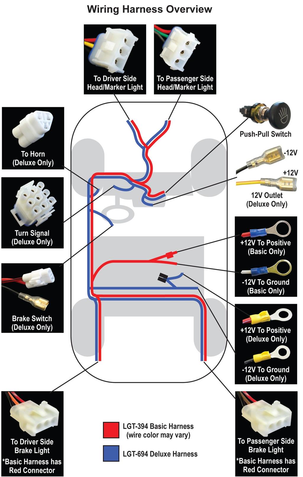
4 Taillight Preparation 1. Cut out the included taillight template following the guidelines. 2. Using painter s tape, tape the template to the driver side rear body of the cart. Follow the guidelines to the right for placement of the template. 3. Use a marker or other marking device to trace the inside contour of the template. If the body is painted, lay painter s tape over the drawn line and redraw over the tape using the template. This helps prevent the paint from chipping. 4. Using a jigsaw or rotary tool, cut out the INSIDE of the marked area. Test fit the taillight. If needed, make any modifications and retest. Once it is fitted properly, remove the tape and sand any rough edges. 5. Flip the template over and complete Steps 2-4 for the passenger side. Wire Harness Installation LGT-394 Basic Harness LGT-694 Deluxe Harness Page 4
5 Page 5

 through the (3)")


6 Gas & Electric Carts 1. Completely remove the front seat bottom assembly. 2. Lay the harness parallel to the driver side of the cart to help with orientation of the harness before installation. 3. Disconnect the fuse holders from each other (deluxe only). 4. From underneath the driver side of the cart, gently run the rear portion of the harness (taillight & battery connections) through the (3) openings in the frame, starting at the front and working towards the rear. 5. Route the taillight and battery connections through the access hole that leads to the battery compartment. Set the battery leads to the side. They will be connected after completing the installation of the harness, lights and/or accessories. 6. Route the taillight leads to the holes that were cut out for the taillights. The shorter lead will go over the driver side inner fender. The longer lead will go behind the battery pack and over the passenger fender. 7. Route the front portion of the harness through the vertical channel on the driver side. Secure with cable ties. NOTE: If you are not installing a brake switch, secure the brake lead to the Page 6
.")
. Jumper 9.")


7 channel with the rest of the harness (deluxe only). 8. If installing a turn signal, disconnect the jumper from the 9-pin connector and discard (deluxe only). If installing a brake switch and no turn signal, switch the (2) 2-pin male connectors on the jumper. Leave the jumper on the harness (deluxe only). Jumper 9. Route the push-pull switch, 12V outlet (deluxe only) and turn signal lead (deluxe only) through the top of the front splash guard into the dash area. The headlight leads will remain in front of the splash guard. 10. Remove the two rivets on the key switch plate and remove the plate to access the dash compartment. Push-Pull Switch Installation Splash Guard NOTE: If installing the LGT-132A deluxe turn signal switch or the KEY-51 key switch, do NOT install the push-pull switch. 1. If powering the lights with the push-pull switch, disconnect the key switch. Using a vice or clamp to secure the plate, safely drill a 1/2 hole on the key switch plate. File any rough edges. 2. Remove the knob, retaining nuts and washer from the push-pull switch and insert the shaft of the switch into the newly drilled hole. Page 7


.")

8 3. Secure using the retaining nuts and washer. Reattach the knob. KEY-51 Key Switch Installation 1. Disconnect the original key switch and remove it from the key switch plate. Retain the hardware. 2. Install KEY-51 in the same location where the original key switch was removed using the original hardware. NOTE: If installing KEY-24, key switch decal, do so before installing KEY Disconnect the push-pull switch at the spade terminals. 4. Connect the two spade connectors from the original key switch to B and I on the back of KEY-51 (shown in Blue). Connect the two spade connectors from the push-pull switch to B1 and L (shown in black). Headlights LGT-304 LGT-304L 1. Connect the headlights to the headlight leads on the main harness. 2. Insert the headlight assemblies into the holes cut out earlier. Once in place, secure with the (8) Included Screws. 3. Secure any loose wires with cable ties and push the excess wires into the dash area. Taillights Page 8 LGT-304/L


 Ground (Basic) + Lead (Deluxe) Ground")


 6V batteries in a series and connect the")
9 1. Connect the taillights to the taillight leads on the main harness. 2. Insert the taillight assemblies into the holes cut out earlier. Once in place, secure with the (8) Included Screws. 3. Secure the taillight wires to the frame with cable ties so they are safely out of the way of the tires. Power Connections + Lead (Basic) Ground (Basic) + Lead (Deluxe) Ground (Deluxe) NOTE: Complete this section once all lights and optional accessories have been installed. 1. Verify the cart is in the TOW position (if equipped) and the key is OFF. 2. Verify any exposed wires and the push-pull switch are not touching the frame or any metal parts on the cart. 3. On a 36V system, select (2) 6V batteries in a series and connect the positive and negative wires of the harness to the positive and negative posts on the battery. On a 48V system with 8V batteries, a voltage reducer is Page 9


 and turn the key ON. 5.")


10 required to reduce the voltage to 12V. On a gas cart, connect the wires to the battery. Tighten the nuts but do not over tighten. Over tightening can destroy the battery posts. Note: Light sparks can be normal when connecting the batteries, but a bright arching flash indicates there is a short in the system. The diagrams below show the batteries in factory configurations. 4. Put the cart in the RUN position (if equipped) and turn the key ON. 5. Turn the lights ON and test the lights and accessories to make sure they function properly. If you are installing a basic light kit, this completes the installation. Turn Signal Assemblies LGT-107A LGT-112 LGT-132A LGT-143 NOTE: If installing a steering column cover, do so before installing the turn signal. 1. Mount the turn signal assembly in a convenient location on the steering column using the included hose clamp for the LGT-112 and the LGT-143. Mount the LGT-132A using the included collar and choose one of the included rubber inserts that best fits the diameter of the steering column. LGT-112 LGT-132A LGT Peel back the floor mat to expose the area around the steering column boot. Remove the rivet securing the boot to the floor and slide the boot out of the way. 3. Using a rotary tool, carefully cut an access hole into the dash compartment large enough to fit the turn signal connectors. The third image below is the Page 10


11 view from inside the dash compartment with the cowl removed. 4. Run the turn signal wires down the steering column, through the access hole and into the dash area. NOTE: If the relay is already installed on the turn signal, it may be helpful to remove the relay before routing the wires under the dash. 5. Access the connectors through the key switch plate. Connect the 9-pin connector on the turn signal switch to the 9-pin connector on the harness. 6. Connect the included flasher relay to the turn signal switch wiring harness. 7. If installing the LGT-132A, remove the push-pull switch at the 4-pin connector and replace it with the LGT-590 relay harness. 8. Once the connections have been made, secure the excess wires in the dash compartment. 9. Slide the boot back in place and replace the rivet (not included). 10. Measure from the bottom of the turn signal to the boot. Using a utility knife, saw or tin snips, cut the LGT-107A, universal turn signal switch wire cover, to the measured length & sand rough edges. 11. Snap the cover around the wires of the turn signal switch and the steering column. Page 11


 pre-drilled holes for the rivets. If your cart has the mounting holes, they will be next to the horn button hole.")
12 12. Reinstall the floor mat. Horns * Horn Decal and Floor Mounted Button are not included with the LGT-112 or LGT-132A Turn Signals. 1. Connect the spade connectors on the horn harness to the back of the horn. You can connect the leads to either terminal. 2. Mount the horn under the driver side front end of the vehicle in a location that does not interfere with the steering or front tires using the Included Hardware. Use the pre-drilled hole or drill a 1/4 hole in a safe location on the golf cart frame. 3. Connect the triangular plug on the horn harness to the triangular plug on the deluxe harness. 4. Secure any loose wires with cable ties. NOTE: If your turn signal does NOT have a horn button, follow steps 4-9 below. 5. Locate the pre-drilled hole for the horn button in the floor of the cart. If the cart has a predrilled hole, it will be behind the driver side floor mat. If not, drill a 5/8 hole through the floor in a safe location. Cut away the floor mat over the hole. 6. Locate the (2) pre-drilled holes for the rivets. If your cart has the mounting holes, they will be next to the horn button hole. Remove the floor mat over the holes with a 7/32 drill bit. If your cart does not have pre-drilled holes, follow Steps 7-8 below. 7. Insert the horn button in the hole from the underside of the cart. Place the horn decal over the horn button. Screw the rubber button cover onto the horn button. Do not tighten. Page 12
 marked hole locations with a 7/32 bit. 9.")
 Rivets. 10.")


13 8. Align the decal so it is straight. Mark the (2) hole locations for the decal onto the floor mat. Remove the horn button, cover and decal. Drill the (2) marked hole locations with a 7/32 bit. 9. Install the horn button and decal using the Included Nut and Rubber Bumper Cover. Align the decal. Secure the decal with the (2) Rivets. 10. Connect the (2) ring terminals from the horn harness to the back of the horn button. You can connect the leads to either terminal. 12 Volt Receptacle and Dual USB Outlet ACC-0058 ACC Find a convenient location above the cup holders to mount the 12V receptacle and/or USB outlet. If mounting on the warning label, do so without covering up the text, if possible. 2. Mark the center of the mounting location with a marking device. 12 Volt Outlet 1. Using a 1 hole saw, drill a hole at the marked location. 2. Insert the 12V receptacle into the hole and mount it with the Included Hardware. 3. Locate the 12V outlet leads. Connect the 12V positive lead to the inside/center terminal of the 12V outlet and the 12V negative lead to the outside terminal. Dual USB Outlet 1. Using a 1-1/2 hole saw (maximum size), drill a hole at the marked location. Page 13


14 2. Insert the dual USB outlet and wires through the protective cap into the drilled hole. Secure it with the threaded retaining ring. 3. The red and black wires will connect to the connections used for the 12V outlet. If needed, cut the wires to the desired length. 4. Use (2) Butt Connectors (not included) to connect the USB wires to the 12V outlet wires. The red wire will connect to the positive 12V wire and the black to the negative wire. NOTE: A fuse holder (ACC-0019) and 15A fuse (ACC-0021) are recommended if direct connecting the USB ports to a 12V battery or voltage reducer. Brake Switches LGT-138 LGT-163 All Brake Switches 1. Verify cart is in the TOW position (if equipped) and the key is OFF. LGT-138 Brake Light Pad Switch 1. Center the LGT-138, brake light pad switch, on the lower portion of the brake pedal assembly. 2. If mounting the switch using the Included Screws, fasten the pad directly to the pedal. If mounting the switch using the Included Rivets, mark the hole locations and drill (6) 3/16 holes through the pedal. Mount the pad with the rivets. 3. Run the brake pad wire under the brake pedal, under the brake assembly and through the opening in the floor. Secure the brake pad wire to the bottom side of Page 14

 Included U-Bolts behind the channel adjacent to the brake pedal assembly.")

15 the assembly using cable ties. 4. Connect the brake pad to the deluxe wire harness. Use a cable tie to secure the wires to the existing wire harness in the channel. Make sure the wires are clear of any moving parts. NOTE: Black ground wire is not used with the LGT-138 brake pad switch. LGT-163 Brake Switch with Time Delay 1. Unlock the brake pedal and chock the wheels. 2. Place the (2) Included U-Bolts behind the channel adjacent to the brake pedal assembly. Slide the threaded ends of the U-bolts through the (4) slots on the brake switch bracket. Tighten the nuts on the U-bolt so they are snug but still adjustable. 3. Position the bracket so the switch is centered above the pedal assembly. Lower it until the switch is activated (it will click). Tighten the nuts to lock the bracket into position. Page 15


16 4. Slide the brake switch wire and the brake lead from the deluxe harness behind the bracket and down the channel with the existing harness. 5. Install the LGT-142, time delay, near the first opening in the frame. Mark the hole location and drill an 1/8 pilot hole. Drill a 1/4 hole through the pilot hole. Mount the time delay with the Included Hardware. 6. Connect the brake switch to the time delay and deluxe harness as shown in the diagram below. 7. Secure all loose wires to the frame with cable ties. Page 16 Your TXT Light Kit is now complete. Please enjoy safely! Watch this installation and others on YouTube:
LGT-312L E-Z-Go TXT Light Bar Bumper Kit Installation Instructions
 LGT-312L E-Z-Go TXT 2014+ Light Bar Bumper Kit Installation Instructions Caution: Please read through the instructions carefully. Before starting this project, remove the system s positive and negative
LGT-311L Bumper LED Light Kit EZ-Go RXV Installation Instructions
 LGT-311L Bumper LED Light Kit EZ-Go RXV Installation Instructions Caution: Please read through the instructions carefully. Before starting this project, remove the system s positive and negative connections
LGT-306L / LB Club Car Precedent LED Light Bar Bumper Kit Installation Instructions
 LGT-306L / LB Club Car Precedent LED Light Bar Bumper Kit Installation Instructions Caution: Please read through the instructions carefully. Before starting this project, remove the system s positive and
LIFT-507 BMF Lift Kit E-Z-Go RXV Gas or Electric Installation Instructions
 LIFT-507 BMF Lift Kit E-Z-Go RXV Gas or Electric Installation Instructions Contents of LIFT-507 E-Z-Go RXV BMF Lift Kit: a (1 ea.) BMF A-Arm Assembly b (1 ea.) Driver Side Shock Tower c (1 ea.) Passenger
LHT CC LIGHT WIRING Instructions for Club Car DS Models
 LHT CC5 1001 LIGHT WIRING Instructions for Club Car DS Models This Light Kit includes: (1) Main Wire Harness with Dual InLine Fuses (1) Headlight Switch (1) Left hand headlight (1) Right hand headlight
Light Kit. will fit FREEDOM E-Z-GO TXT installation instructions
 Revised July 23 2014 02-023 Light Kit will fit FREEDOM E-Z-GO TXT installation instructions included: tools needed: Tail lights 2 Headlights 2 Tail Lights 1 Wiring Harness 8 Screws Straps Phillips Head
Instructions for Yamaha G14/G16/G19/G22 Models
 Instructions for Yamaha G14/G16/G19/G22 Models The Light Kit includes: (31483) Brakelight Connector Turn Signal Connector (1) Main Wire Harness with Positive & Negative In-line Fuses. (1) Head Light Switch.
Tail lights. Headlights
 Revised December 2014 02-017 Light Kit will fit Yamaha G-Series* installation instructions included: tools needed: 2 Headlights 2 Tail Lights Wiring Harness Screws Straps Hazard Switch Phillips Head Screw
INSTALLATION MANUAL. Level of Difficulty. Parts List. Product Image. Tools Required. Notes and Maintenance. Torque Specifications.
 INSTALLATION MANUAL Parts List 1 Bull bar 2 Upper frame mounting bracket 1 Driver / left lower frame mounting bracket 1 Passenger / right lower frame mounting bracket 2 Button head bolt, 6mm 4 Flat washer,
Turn Signal / Horn Kit PN 7101 by All years Polaris RZR 1000 and RZR 900, 900-4, 900 trail, 900S and 900XC STOP - THIS KIT IS DESIGNED
 All years Polaris RZR 1000 and 1000-4 2015 RZR 900, 900-4, 900 trail, 900S and 900XC STOP - THIS KIT IS DESIGNED SPECIFICALLY FOR ALL YEAR AND MODEL POLARIS RZR 1000 AND 1000-4. ALSO THE 2015 POLARIS RZR
FOG LAMPS INSTALL KIT
 FOG LAMPS INSTALL KIT PT CRUISER INSTALLATION INSTRUCTIONS Read entire instructions thoroughly before starting. For proper aiming of fog lamps, follow procedures in the service manual. NOTES: Left and
INSTALLATION INSTRUCTIONS
 INSTALLATION INSTRUCTIONS Accessory Application Publications No. S 1998 CIVIC 2/3/4-DOOR All 18767 Issue Date SEP 1997 PARTS LIST Fog Light Kit: P/N 08V31-S01-100 Right fog light (marked R ) Fuse label
2016 HONDA 1000 Pioneer PN 3102 Turn signal / horn kit rev nc
 2016 Honda 1000 Pioneer STOP - THIS KIT IS DESIGNED SPECIFICALLY FOR 2016 HONDA 1000 PIONEER IF YOUR MACHINE IS NOT THIS MODEL DO NOT PROCEED. THIS KIT DOES NOT WORK ON THE PIONEER 500 nor 700 S. Contact
P3066 INSTALLATION MANUAL
 P3066 INSTALLATION MANUAL Parts List 1 Grille guard 1 Driver / left frame bracket Level of Difficulty Moderate Scan for helpful install tips 1 Passenger / right frame bracket 1 Driver / left top bracket
SCION FRS FOG LIGHTS. Part Number: SFR-313
 Part Number: SFR-313 Kit Contents Item # Quantity Reqd. Description 1 2 Light Housings 2 2 Fog Light bezels 3 1 Harness bag 4 1 User s card 5 1 Switch 6 1 Fuse jumper Hardware Bag Contents Item # Quantity
INSTALLATION INSTRUCTIONS
 Rear Vision System Aftermarket and Factory 5.0, 8.4 and 6.1 MyGig Touch Screen Display (Factory Display requires Chrysler/Dodge dealer to activate) 2009 Current* Dodge Ram (Kit part number 1009-6503) *NOTE:
LIFT-504. BMF Lift Kit. Yamaha G22 Gas or Electric. Installation Instructions
 LIFT-504 BMF Lift Kit Yamaha G22 Gas or Electric Installation Instructions Contents of LIFT-504 Yamaha G22 BMF Lift Kit: a (1 ea.) BMF A-Arm Assembly b (1 ea.) Driver Side Shock Tower c (1 ea.) Passenger
6945 (12v) 6944 (24V) installation instructions
 6944 (24V) installation instructions") 6945 (12v) 6944 (24V) installation instructions included: tools needed: Cordless drill Breezeeasy Fan Mounting brackets 1/4 Drill Bit 10mm Socket Hardware Pack 10mm Wrench Fuse Assembly Wire Stripper Crimper
6945 (12v) 6944 (24V) installation instructions included: tools needed: Cordless drill Breezeeasy Fan Mounting brackets 1/4 Drill Bit 10mm Socket Hardware Pack 10mm Wrench Fuse Assembly Wire Stripper Crimper
TOYOTA FJ CRUISER 2007 AUXILIARY LIGHTS Preparation
 TOYOTA FJ CRUISER 2007 AUXILIARY LIGHTS Preparation Part Number: PT297-35061 Kit Contents Item # Quantity Reqd. Description 1 2 Driving Lamp Assembly 2 1 Switch Harness 3 1 Lamp Harness 4 2 Stone Shield
LHT EZ HEAD & TAIL LIGHT KIT Instructions for EZGO TXT Models
 LHT EZ2 2001 HEAD & TAIL LIGHT KIT Instructions for EZGO TXT Models The Headlight Kit includes: (1) Complete Light Kit Harness (1) Wire Harness for brake lights (optional) (1) 20 amp light switch. (1)
WOC & WOC Top & Back Installation Instructions
 Shown with optional Sun Roof WOC-900500-2 & WOC-900501-2 Top & Back Installation Instructions Install Order! Heater Door System Wiper on to Windshield Windshield Rear Panel Top Panel Tools needed: 5/16
INSTALLATION INSTRUCTIONS
 9002-6513 Rear Vision System W/ Zoom Aftermarket and Factory 8.4 Touch Screen Display (Factory Display requires Chrysler/Dodge dealer to activate) 2009 2012 RAM (Part B) 2013 Current RAM (Part A) NOTE:
LPE C5 Battery Relocation Kit
 LPE C5 Battery Relocation Kit The LPE C5 Corvette battery relocation kit improves vehicle weight distribution by moving weight to the rear of the vehicle. The improved weight distribution increases traction
Setting the World s Performance Standards
 Setting the World s Performance Standards 743 East Iona Road, Idaho Falls, ID 83401, (208) 529-0244 Fax (208) 529-9000 Forced Air Hot Air Elimination Kit (Bed Fan Kit) For 800 RZR-4 P/N 67-165 Kit Contents:
TOYOTA TACOMA Part Number: TTA-BGB16-DRL TTA-BGP16-DRL
 TOYOTA TACOMA 2016-17 Date: 10.29.2016 Billet Grille w/led DRL Part Number: TTA-BGB16-DRL TTA-BGP16-DRL Kit Contents Item # Quantity Reqd. Description 1 2 LED DRL 2 1 Driver Box 3 1 Switch 4 1 User Card
Wolverine Turn Signal / Horn Kit 2102
 All years Yamaha Wolverine STOP - THIS KIT IS DESIGNED SPECIFICALLY FOR ALL YEAR AND MODELS YAMAHA WOLVERINE. IF YOUR MACHINE IS NOT ONE OF THESE MODELS DO NOT PROCEED. Contact Ryco Motorsports or your
SAFETY THIS PRODUCT IS FOR OFFROAD USE ONLY. ALL LIABILITY FOR INSTALLATION AND USE RESTS WITH THE OWNER.
 SAFETY Your safety and the safety of others is very important. In order to help you make informed decisions about safety, we have provided installation instructions and other information. These instructions
TOYOTA PRIUS C FOG LIGHT (Halogen & LED)
") TOYOTA PRIUS C 2012-14 FOG LIGHT (Halogen & LED) Part Number: TPC-312 / TPC-812 Kit Contents Item # Quantity Reqd. Description 1 2 Fog Lamps 2 2 Bezels 3 1 Switch Assembly 4 1 Fog Light Operation guide
TOYOTA PRIUS C 2012-14 FOG LIGHT (Halogen & LED) Part Number: TPC-312 / TPC-812 Kit Contents Item # Quantity Reqd. Description 1 2 Fog Lamps 2 2 Bezels 3 1 Switch Assembly 4 1 Fog Light Operation guide
STREET SCENE EQUIPMENT,INC.
 STREET SCENE EQUIPMENT,INC. 950-76570 BLACK CHROME 365 McCormick Avenue 950-77570 SATIN FINISH Costa Mesa, Ca. 92626 950-78570 CHROME FINISH Phone (714) 426-0590 Fax (714) 426-0591 2007-2008 TOYOTA TUNDRA
Air Conditioner for M915 A0/A1 Truck
 RD-2-4530-0 Air Conditioner for M915 A0/A1 Truck INSTALLATION INSTRUCTIONS Install refrigerant compressor per instructions provided with compressor mount kit. CAUTION: Edges of sheet metal can be sharp!
Electric Power Steering Installation in the Pantera. by Gerry Romack & Alan Cameron
 Electric Power Steering Installation in the Pantera by Gerry Romack & Alan Cameron 1. Harness with controller 2. Power Wire battery 3. Steering assembly 4. Hall Effect Speed Sensor Fused Ignition relay
TTR225/250 DUAL S PORT K IT I NSTALLATION I NSTRUCTIONS
 TTR225/250 DUAL S PORT K IT I NSTALLATION I NSTRUCTIONS KIT CONTENTS Inspect Your Kit Your kit will include the following items A. TTR225/250 Instructions and Wiring Diagrams Read through the entire instruction
Bucket Harness. Installation Instructions. for Electric Club Car Precedent
 Bucket Harness for Electric Club Car Precedent Installation Instructions Electric Club Car Precedents manufactured after January 1, 2008 require an additional harness to allow the installation of light
Part Number: TCA-712SE
 Date: 09.04.2013 TOYOTA CAMRY SE 2012-14 LED DRL Part Number: TCA-712SE Kit Contents Item # Quantity Reqd. Description 1 2 DRL s bezels w/led DRL 2 1 Driver Box 3 1 Harness bag 4 1 User s card 5 1 Cushion
Remove black panel shown. Save 6 retaining pins for re-install later. Pry up on center part of pin first. Then pry out entire retaining pin.
 2005-2009 Ford Mustang V6 Fog Light Wiring Kit Parts List: Quantity: Tools Required: Wiring harness 1 Flat head screwdriver Supplemental wire leads 2 Ratchet & Socket set OR Wire tap red 2 Adjustable Wrench
YARIS 4-DOOR 2007 INTERIOR LIGHT UPGRADE
 Document # 3999 4/26/06 4-DOOR 2007 INTERIOR LIGHT UPGRADE Preparation Part Number: 00016-52060 Code: IL1 Kit Contents Item # Quantity Reqd. Description 1 1 12 Light Guide 2 1 7 Light Guide 3 1 Hardware
Fitting Instructions
 Reverse Park Assist Suitable for: Nissan Navara Kit Part No: 5466XX NP00 Tow-Pro Wiring Kit Fitting Instructions Accessory Kit Estimated Fitting Time: 0 Minutes FI98 Page 0 of 5 General Notes Read through
LIFT Drop Spindle Lift Kit E-Z-Go RXV Gas or Electric Installation Instructions
 LIFT-107 6 Drop Spindle Lift Kit E-Z-Go RXV Gas or Electric Installation Instructions Contents of LIFT-107 E-Z-Go RXV Drop Spindle Lift Kit: a (1 ea.) Driver Side Spindle b (1 ea.) Passenger Side Spindle
Not Included. Rear Half Harness
 Basic Light Kit 60102 Caution! Wear appropriate eye protection! Disconnect the battery or batteries. Place run/tow switch in tow position before disconnecting the batteries on models using that feature.
INSTALLATION INSTRUCTIONS FORD SUPER DUTY NOTE: (Vehicle Retains Tow Hook) PART # P3064
 PART # P3064") INSTALLATION INSTRUCTIONS 2011-14 FORD SUPER DUTY 250-550 NOTE: (Vehicle Retains Tow Hook) PART # P3064 PARTS LIST: Qty Description Qty Description 1 Grill Guard 2 10mm x mm Hex Bolts 1 Driver/Left Lower
INSTALLATION INSTRUCTIONS 2011-14 FORD SUPER DUTY 250-550 NOTE: (Vehicle Retains Tow Hook) PART # P3064 PARTS LIST: Qty Description Qty Description 1 Grill Guard 2 10mm x mm Hex Bolts 1 Driver/Left Lower
TOYOTA VENZA 2009 TRAILER WIRE HARNESS Procedure
 Part Number: PT791-0T099 Kit Contents Item # Quantity Reqd. Description 1 1 Trailer Wire Harness Module 2 1 4-Flat Harness 3 1 Battery Power Wire Harness 4 1 Mounting Bracket, 4-Flat 5 2 Screw #10-24 6
TOYOTA VENZA 2009 TRAILER WIRE HARNESS Procedure
 Part Number: PT791-0T099 Kit Contents Item # Quantity Reqd. Description 1 1 Trailer Wire Harness Module 2 1 4-Flat Harness 3 1 Battery Power Wire Harness 4 1 Mounting Bracket, 4-Flat 5 2 Screw #10-24 6
TOYOTA YARIS HATCHBACK INTERIOR LIGHT UPGRADE Preparation
 Preparation Part Number PTS21-52062-08 NOTE: Part number of this accessory may not be the same as the part number show Kit Contents Item # Quantity Reqd. Description 1 1 12 Light Guide 2 1 7 Light Guide
Ford Mustang V6 OEM-Style Fog Light Kit Parts List: Quantity: Tool List:
 2015-2017 Ford Mustang V6 OEM-Style Fog Light Kit Parts List: Quantity: Tool List: LED Foglights/ Bezels 2 Flat head & Phillips screwdriver (if you ordered part#3600) Ratchet & Socket set OR Wiring harness
Depress each tab as you pull the bezel off. The bezels are tight. L.H. shown.
 2013-2014 Ford Mustang V6 & Boss 302 Lower Valance Fog Light Kit Parts List: Quantity: Tool List: Fog light & bulb with bracket 2 Flat head & Phillips screwdriver Black bezels 2 Ratchet & Socket set OR
TOYOTA PRIUS FOG LIGHT (Halogen or LED)
") Part Number: TPR-413 / TPR-813 Kit Contents Item # Quantity Reqd. Description 1 2 Fog Lamps 2 1 Lower Grill 3 1 Switch Assembly 4 1 Fog Light Operation guide 5 1 Harness Bag Hardware Bag Contents Item
Part Number: TPR-413 / TPR-813 Kit Contents Item # Quantity Reqd. Description 1 2 Fog Lamps 2 1 Lower Grill 3 1 Switch Assembly 4 1 Fog Light Operation guide 5 1 Harness Bag Hardware Bag Contents Item
Part Number: TAV-713 TOYOTA AVALON LED DRL
 Part Number: TAV-713 Kit Contents Item # Quantity Reqd. Description 1 2 DRL s bezels w/led DRL 2 1 Driver Box 3 1 Harness bag 4 1 User s card 5 1 Cushion pad 6 1 Switch 7 2 Drill Jigs Hardware Bag Contents
TOYOTA TACOMA LED DRL Black-Out
 TOYOTA TACOMA 2013 - LED DRL Black-Out Part Number: 00016-35021 Accessory Code: LDBO10 Conflicts - Fog Lights Kit Contents Item # Quantity Reqd. Description 1 2 DRL Housing 2 1 Driver Box 3 1 Harness bag
Model 377, 379, 386, 388, Sleeper no window
 Installation Manual Model 377, 379, 386, 388, 389 63 Sleeper no window 2390 Blackhawk Road P.O. Box 6007 Rockford, IL 61125 www.nitesystem.com 1-866-204-8570 NITE Plus Installation Procedures 1-2 Table
TOYOTA COROLLA LED DRL eyebrow. Part Number: TCO-DRL
 Part Number: TCO-DRL Kit Contents Item # Quantity Reqd. Description 1 2 DRL s bezels w/led DRL 2 1 Driver Box 3 1 Harness bag 4 1 User s card 5 1 Switch Hardware Bag Contents Item # Quantity Reqd. Description
TOYOTA RAV4/HV INTERIOR LIGHT KIT Preparation
 Preparation Part Number: PT413-42130 Kit Contents Item # Quantity Reqd. Description 1 1 Wire Harness 2 3 Hardware Bag Contents Item # Quantity Reqd. Description 1 20 Cable Tie 2 2 Scotchlok 3 2 Foam Pad
SAFETY THIS PRODUCT IS FOR OFFROAD USE ONLY. ALL LIABILITY FOR INSTALLATION AND USE RESTS WITH THE OWNER.
 SAFETY Your safety and the safety of others is very important. In order to help you make informed decisions about safety, we have provided installation instructions and other information. These instructions
I. Before starting installation
 5. Park the vehicle on a clean, dry, flat, level surface and block the tires so the vehicle cannot roll in either direction. A. Disconnect battery cables 1. Disconnect the negative cable first, then the
INSTALLATION INSTRUCTIONS
 AUTOMOTIVE PRODUCTS, INSTALLATION INSTRUCTIONS ULTIMATE BULL BAR APPLICATION: 2009-2018 Dodge Ram 1500 (Excl. Rebel Model) 2019 Dodge Ram 1500 Classic PART NUMBER: 32-1960, 32-1965, 32-1960L, 32-1965L
INSTALLATION INSTRUCTIONS
 Rear Vision System Tailgate Emblem Camera Mirror Display 2009-Current Ford F-150 and 2010-Current Super Duty (Kit part number 1008-9527) Kit Contents: Mirror Tailgate Emblem Mount with Camera Interior
TOYOTA PRIUS C FOG LIGHT
 TOYOTA PRIUS C 2012 - FOG LIGHT Part Number: 00016-47160 Accessory Code: LF10 Conflicts NONE Kit Contents Item # Quantity Reqd. Description 1 2 Fog Lamps 2 2 Fog Lamp s bezels 3 1 Switch Assembly 4 1 Fog
TOYOTA RAV TRAILER WIRE HARNESS Preparation
 Preparation Part Number: PU322-42013-UW Kit Contents Item # Qty Description 1 1 Trailer Module Harness 2 1 Trailer 4-Flat Harness 3 1 Trailer Power Wire Harness 4 1 Mounting Bracket, 4-Flat 5 2 Screw #10-24
JODALE PERRY. Parts List & Mounting Instructions. Jacobsen HR9016 JDP BUILT FOR LIFE
 JODALE PERRY Parts List & Mounting Instructions Jacobsen HR9016 JDP BUILT FOR LIFE Jacobsen HR9016 Mounting Instructions Standard Parts 1 - LH Rear Mounting Bracket 1 - RH Rear Mounting Bracket 1 - Front
TOYOTA COROLLA L, LE FOG LIGHT (Halogen and LED) Part Number: TCO-314 / TCO-814
 Part Number: TCO-314 / TCO-814") TOYOTA COROLLA L, LE 2014-16 FOG LIGHT (Halogen and LED) Part Number: TCO-314 / TCO-814 Kit Contents Item # Quantity Reqd. Description 1 2 Light Housings 2 2 Fog Light bezels 3 1 Switch Assembly 4 1 Fog
TOYOTA COROLLA L, LE 2014-16 FOG LIGHT (Halogen and LED) Part Number: TCO-314 / TCO-814 Kit Contents Item # Quantity Reqd. Description 1 2 Light Housings 2 2 Fog Light bezels 3 1 Switch Assembly 4 1 Fog
CAMRY STRIP LED DRL TOYOTA Part Number: Accessory Code: LDRS10. PIO / DIO Rev. A 02/26/13. Doc
 Doc. 02.126.00 TOYOTA CAMRY PIO / DIO Rev. A 2013-02/26/13 STRIP LED DRL Part Number: 00016-32280 Accessory Code: LDRS10 Conflicts - Only works on Camry SE Kit Contents Item # Quantity Reqd. Description
Your Legal Fuel Tank Source.
 February 23, 2015 IS# 808 Page 1 of 13 THANK YOU FOR PURCHASING A TRANSFER FLOW 40 GALLON TOOLBOX REFUELING SYSTEM. PLEASE READ THE FOLLOWING PROCEDURES CAREFULLY BEFORE STARTING THE INSTALLATION. CAUTION:
Part Number: SFR-713. Hardware Bag Contents. General Applicability All models. Conflicts - Fog Lights. Date: SCION FRS LED DRL
 Date: 01.30.2014 SCION FRS 2013-2015 LED DRL Part Number: SFR-713 Kit Contents Item # Quantity Reqd. Description 1 2 DRL s bezels w/led DRL 2 1 Driver Box 3 1 Harness bag 4 1 User s card 5 1 Switch Hardware
INSTALLATION INSTRUCTIONS FORD F-150 2WD & 4WD RETAINS FACTORY TOW HOOKS PART #P3063
 INSTALLATION INSTRUCTIONS FORD F-150 2WD & 4WD RETAINS FACTORY TOW HOOKS PART #P3063 PARTS LIST: 1 Grille Guard 2 10-1.5mm Nylon Lock Nuts 1 Driver/Left Frame Mounting Bracket 4 12mm Plastic Washers 1
HIGH FLOW COLD AIR INTAKE SYSTEM INSTALLATION INSTRUCTIONS D , D A
 HIGH FLOW COLD AIR INTAKE SYSTEM INSTALLATION INSTRUCTIONS D760-0320, D760-0320A 1992-95 325i, is 1995 M3 (3.0L) Parts List: 1 Intake Tube 1 Silicone Hose 1 Air Flow Meter Bracket 1 Hose Clamp (#36z) 1
SCION tc 2014 FOG LIGHT KIT
 Part #: PT413-21140 Conflicts: P/N PTR11-21100 Lowering Springs (CA only) Kit Contents: Wire Ties Self-Tapping Screws Switch Relay Fog Light Bezel, Left and Right Side Wire Harness Fog Lamp, Left and Right
Fig A ADDICTIVE DESERT DESIGNS. Preparation: Removal: Release these clips
 Preparation: Disconnect the negative battery terminal. Park the vehicle on level ground and set the emergency brake. We recommend reading through the installation instructions in whole before performing
Rear Vision System Liftgate Emblem Camera for Aftermarket Display Ford Flex (Kit part number )
") Rear Vision System Liftgate Emblem Camera for Aftermarket Display 2009-2012 Ford Flex (Kit part number 1008-6509) Kit Contents: Liftgate Emblem Mount with Camera Chassis Harness with RCA (Note: In some
Rear Vision System Liftgate Emblem Camera for Aftermarket Display 2009-2012 Ford Flex (Kit part number 1008-6509) Kit Contents: Liftgate Emblem Mount with Camera Chassis Harness with RCA (Note: In some
PERFORMANCE HOOD VENTS CONTENTS: Left Side Hood Vent (1) Right Side Hood Vent (1) Mounting Bracket, Inner (2) Mounting Bracket, Outer (2) OE Hood Temp
 Right Side Hood Vent (1) Mounting Bracket, Inner (2) Mounting Bracket, Outer (2) OE Hood Temp") CONTENTS: Left Side Hood Vent (1) Right Side Hood Vent (1) Mounting Bracket, Inner (2) Mounting Bracket, Outer (2) OE Hood Template (1) HARDWARE: Mounting Bracket, Inner X 2 Phillips Screw X 8 Mounting
CONTENTS: Left Side Hood Vent (1) Right Side Hood Vent (1) Mounting Bracket, Inner (2) Mounting Bracket, Outer (2) OE Hood Template (1) HARDWARE: Mounting Bracket, Inner X 2 Phillips Screw X 8 Mounting
SAFETY THIS PRODUCT IS FOR OFFROAD USE ONLY. ALL LIABILITY FOR INSTALLATION AND USE RESTS WITH THE OWNER.
 SAFETY Your safety and the safety of others is very important. In order to help you make informed decisions about safety, we have provided installation instructions and other information. These instructions
INSTALLATION INSTRUCTIONS
 Rear Vision System Liftgate Emblem Camera Mirror Display 2009-2012 Ford Flex (Kit part number 1008-9527) Kit Contents: Mirror Liftgate Emblem Mount with Camera Interior (shorter) Harness Chassis (longer)
SAFETY THIS PRODUCT IS FOR OFFROAD USE ONLY. ALL LIABILITY FOR INSTALLATION AND USE RESTS WITH THE OWNER.
 SAFETY Your safety and the safety of others is very important. In order to help you make informed decisions about safety, we have provided installation instructions and other information. These instructions
INSTALLATION INSTRUCTIONS DODGE DAKOTA 2 KIT # 682 (2WD), 692 (4WD) 3 KIT # 683 (2WD), 693 (4WD)
, 692 (4WD) 3 KIT # 683 (2WD), 693 (4WD)") INSTALLATION INSTRUCTIONS 1997-1999 DODGE DAKOTA 2 KIT # 682 (2WD), 692 (4WD) 3 KIT # 683 (2WD), 693 (4WD) Installation of a Performance Accessories body lift kit will change the vehicle s center of gravity
INSTALLATION INSTRUCTIONS 1997-1999 DODGE DAKOTA 2 KIT # 682 (2WD), 692 (4WD) 3 KIT # 683 (2WD), 693 (4WD) Installation of a Performance Accessories body lift kit will change the vehicle s center of gravity
Deuce/Ace Installation Instructions
 HARDWARE KIT: Upper Mounting Plate: 2-7/16" (11mm) X 3.5" bolts 2-7/16" flange nuts 2-2" spacers 2-7/16" trim cap mounting washers 2 - plastic trim caps TOOLS NEEDED: safety glasses wrenches 16mm or 5/8"
Fitting Instructions
 Reverse Park Assist Suitable for: Isuzu MU-X Kit Part No: / 5466XX D-Max Tow-Pro Wiring Kit Fitting Instructions Suitable for: Isuzu MU-X / D-Max Accessory Kit Estimated Fitting Time: 0 Minutes FI967 Page
pg 2 Disassembly, Wire and Amplifier Plate Installation pg 9 Glovebox Subwoofer Installation pg 13 Kick Panel Speakers Installation
 RZ3-5KRC RZR XP1000 & 2015+ RZR900 with Ride Command SSV Works 5 Speaker Audio Kit pg 2 Disassembly, Wire and Amplifier Plate Installation pg 9 Glovebox Subwoofer Installation pg 13 Kick Panel Speakers
INSTALLATION INSTRUCTIONS
 Accessory Application Publication No. INSTALLATION INSTRUCTIONS WINCH MOUNT KIT P/N 08L77-HL3-A00 SXS700M4/M2 Honda Dealer: Please give a copy of these instructions to your customer. MII 14607 Issue Date
Mustang Shaker
 2005-2009 Mustang Shaker CDC #110050 ( 05/ 06) or 0711-7000-01 ( 07/ 09) Component Check List: Quantity/Description Part # CDC Installer 1 - Engine Cover Assembly 114050 1 - Aluminum Shaker Scoop 183020
RIM Hood For Aeromaster Bodies
 RIM Hood For Aeromaster Bodies Service Guide WARNING: Hood should be opened by releasing the hold-down straps, lifting the hood, and engaging the prop rod. Be sure prop rod is properly engaged before working
PHASE 3 POWERSPORTS AUDIO KIT MAVERICK X3 CAN-AM. pg 3 Disassembly, Wire and Amplifier Plate Installation. pg 11 Dash Kit Installation
 CAN-AM MAVERICK X3 PHASE 3 POWERSPORTS AUDIO KIT pg 3 Disassembly, Wire and Amplifier Plate Installation pg 11 Dash Kit Installation pg 15 Underseat Subwoofer Installation pg 19 Dash Speaker Pods Installation
INSTALLATION INSTRUCTIONS
 Accessory Application Publications No. INSTALLATION INSTRUCTIONS S (LX, EX) CIVIC 2- AND 4- DOOR AII 25449 Issue Date SEP 2003 NOTE: Fog Lights cannot be installed if the vehicle is equipped with an optional
Z-Gate Universal Shifter
 Installation Instructions Z-Gate Universal Shifter Fits: GM, Ford, Lincoln and Chrysler Transmissions See Application Guide for Specific Applications Part #80681 Rev 06/01/2018 WORK SAFELY! For maximum
led light Kit included: tools needed: 2 LED Headlights 2 LED Tail Lights Wiring Harness Screws Straps Rocker Switch WILL FIT CLUB CAR DS
 led light Kit WILL FIT CLUB CAR DS 02-033 included: tools needed: 2 LED Headlights 2 LED Tail Lights Wiring Harness Screws Straps Rocker Switch Phillips head screw driver Cutting Tool Sandpaper Power Drill
INSTALLATION INSTRUCTIONS
 INSTALLATION INSTRUCTIONS Accessory HITCH Application 2012 CROSSTOUR Publications No. AII 46198 Issue Date JULY 2011 PARTS LIST Trailer Hitch Kit P/N 08L92-TP6-101 Upper spacer A (5 mm) (Some are not used.)
INSTALLATION INSTRUCTIONS
 Accessory Application Publications No. INSTALLATION INSTRUCTIONS S (DX, HX, VP) 2005 CIVIC 2- AND 4- DOOR AII 27865-30866 Issue Date SEP 2005 NOTE: Fog Lights cannot be installed if the vehicle is equipped
RZ3-5K Polaris RZR XP 1000 & 900 Kicker 5 Speaker Audio Kit
 PO H PWER PO 5 O KIT I E D U A S A TS S I R LA R Z R R O SP pg 2 pg 9 pg 13 pg 25 pg 29 Disassembly, Wire and Amplifier Plate Installation Glovebox Subwoofer Installation Kick Panel Speakers Installation
Mustang CLASSIC LIGHT BAR INSTALLATION INSTRUCTIONS CDC #
 1990-1993 Mustang CLASSIC LIGHT BAR INSTALLATION INSTRUCTIONS CDC # 101000 Kit Components: 1 Light Bar 4 Bolts ( 5 / 16-18 x 2.5 ) #182010 4 Washer #182005 4 Shims #182009 2 Dark Blue Connectors #182004
LED Fog Light. Conflicts Note: 1832, 1852, 1856, 1872, General Applicability Fits Models
 LED Fog Light Year & Model Part Number 2017 Corolla TCO-817 Conflicts Note: 1832, 1852, 1856, 1872, 1874 General Applicability Fits Models 1863 1866 1864 1865 Additional Items Required For Installation
INSTALLATION INSTRUCTIONS
 INSTALLATION INSTRUCTIONS Part# 22-7810 Jeep JK/JKU ARB Mounting Kit 2007-2018.5 For the most up to date instructions please visit www.updownair.com www.updownair.com 833 226 4863 IMPORTANT INFORMATION
INSTALLATION INSTRUCTIONS
 INSTALLATION INSTRUCTIONS Accessory TRAILER HITCH Application 201 CR-V Publications No. Issue Date PARTS LIST Trailer Hitch Kit P/N 08L92-T0A-100 Hex nut, 12 mm Trailer hitch Hitch pin Hitch pin clip Ball
INSTALLATION INSTRUCTIONS
 Accessory Application Publication No. INSTALLATION INSTRUCTIONS HORN MOUNT P/N 08Z77-HL4-A00 SXS1000M3/M3P/M5D/M5P Honda Dealer: Please give a copy of these instructions to your customer. MII 15262 Issue
INSTALLATION INSTRUCTIONS
 INSTALLATION INSTRUCTIONS Accessory Application Publications No. S CIVIC 2 AND 4-DOOR (EX, LX) AII 24188 Issue Date AUG 2002 NOTE: Fog Lights cannot be installed if the vehicle is equipped with an optional
INSTALLATION INSTRUCTIONS
 INSTALLATION INSTRUCTIONS Accessory ACCESSORY HANDSFREELINK Application 2010 ACCORD 2 AND 4-DOOR Publications No. AII 42231 Issue Date AUG 2009 PARTS LIST HFL retainer HFL Attachment Kit P/N 08E02-TA0-100
RZ3-5A Polaris RZR XP 1000 & 900 SSV Works 5 Speaker Audio Kit
 RZ3-5A Polaris RZR XP 1000 & 900 SSV Works 5 Speaker Audio Kit pg 2 Disassembly, Wire and Amplifier Plate Installation pg 9 Glovebox Subwoofer Installation pg 13 Kick Panel Speakers Installation pg 25
INSTALLATION INSTRUCTIONS
 INSTALLATION INSTRUCTIONS Part# 22-7810 Add On Kit for Your ADS System Contents: Complete Install Kit for Your ARB CKMTA12V Compressor For the most up-to-date instructions please visit www.updownair.com
INSTALLATION INSTRUCTIONS
 INSTALLATION INSTRUCTIONS Accessory Accessory Hands Free Link Application 2008 ACCORD 2 AND 4-DOOR Publications No. AII 38281 Issue Date NOV 2007 PARTS LIST Attachment Kit P/N 08E02-TA0-100 trim retainer
Installation Instructions Z-Gate Shifter
 Installation Instructions Z-Gate Shifter Part Number 80681 1998, 2001 by B&M Racing and Performance Products The B&M Z-Gate shifter can be used in vehicles equipped with most popular three speed automatic
JEEP WRANGLER INSTALLATION GUIDE PART NUMBER: JEEP DAYTIME RUNNING LIGHT (DRL) KIT UNIVERSAL HARDWARE KIT CONTENTS GENERAL APPLICABILITY
 KIT UNIVERSAL HARDWARE KIT CONTENTS GENERAL APPLICABILITY") JEEP WRANGLER INSTALLATION GUIDE PART NUMBER: 250-1024-JEEP DAYTIME RUNNING LIGHT (DRL) KIT GENERAL APPLICABILITY UNIVERSAL KIT CONTENTS ITEM QTY DESCRIPTION 1 2 LED DAYTIME RUNNING LIGHTS* 2 1 CONTROL
JEEP WRANGLER INSTALLATION GUIDE PART NUMBER: 250-1024-JEEP DAYTIME RUNNING LIGHT (DRL) KIT GENERAL APPLICABILITY UNIVERSAL KIT CONTENTS ITEM QTY DESCRIPTION 1 2 LED DAYTIME RUNNING LIGHTS* 2 1 CONTROL
INSTALLATION INSTRUCTIONS
 INSTALLATION INSTRUCTIONS Accessory Application Publication No. MII 15249 WINCH MOUNT KIT P/N 08L70-HL3-A41 SXS700/M4/M2 Issue Date September 2015 PARTS LIST No. Description Qty (1) Winch bracket 1 (2)
SUT-250-S (These instructions are used for SUT-250-SCLC also)
") SUT-250-S (These instructions are used for SUT-250-SCLC also) Torque wrench, carpenters square, wire cutters, Phillips screwdriver, 7/16, 9/16, and 3/4 combination wrenches, ratchet, 9/16, 3/4, 13/16,
SUT-250-S (These instructions are used for SUT-250-SCLC also) Torque wrench, carpenters square, wire cutters, Phillips screwdriver, 7/16, 9/16, and 3/4 combination wrenches, ratchet, 9/16, 3/4, 13/16,
PRODUCT INSTRUCTIONS
 PRODUCT INSTRUCTIONS Thank you for purchasing genuine Design Engineering, Inc. products. Be sure to always wear the proper safety equipment when installing any DEI product. Design Engineering Inc. WILL