Function Description Of Roll-over Bar
|
|
|
- Terence Tate
- 5 years ago
- Views:
Transcription

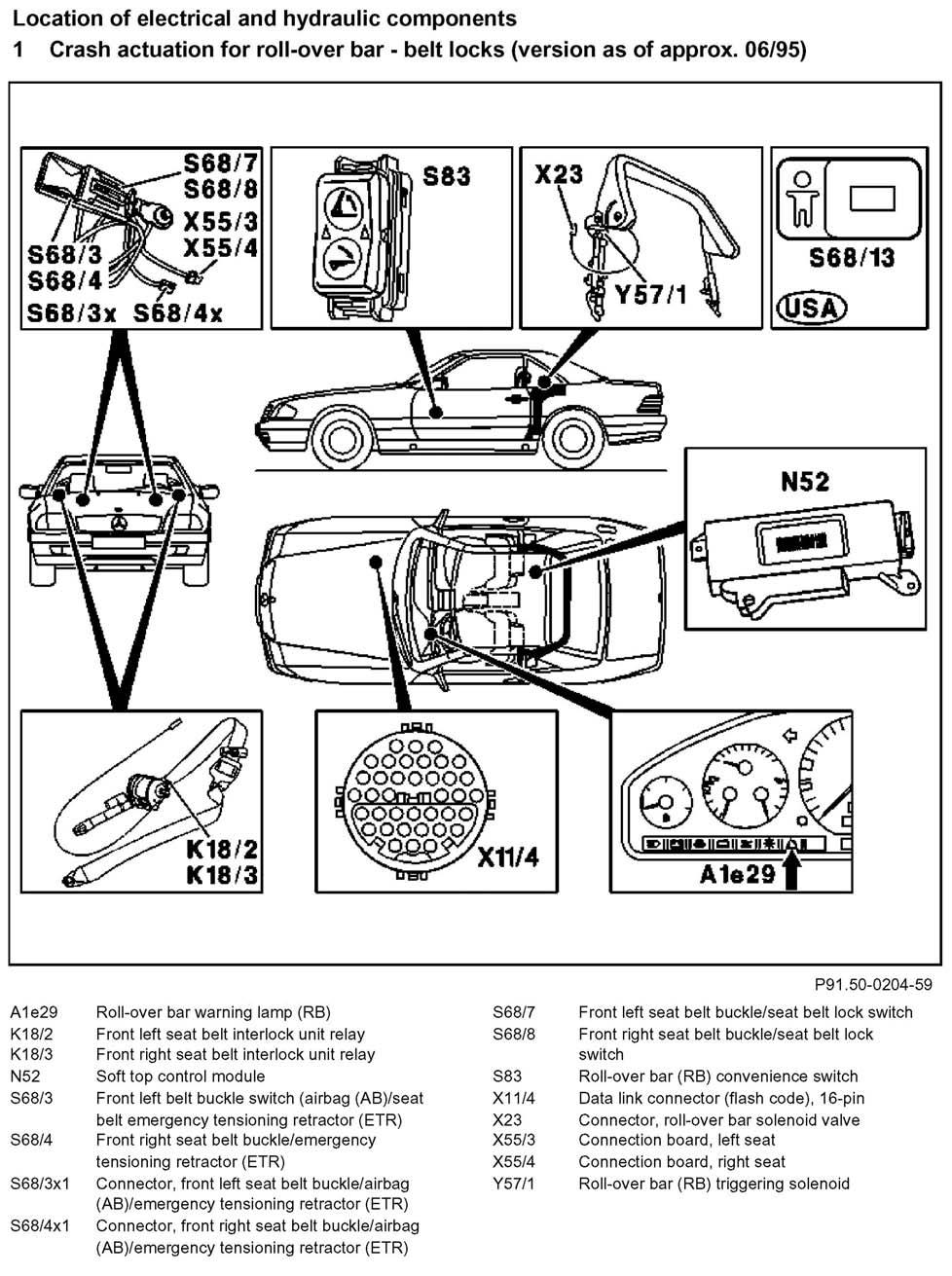
1 Function Description Of Roll-over Bar

2 General The U-shaped roll-over bar is mounted on two main bearings on the left and right center pillars. In the retracted state the roll-over bar is positioned in front of the soft top compartment. In the event of an accident or critical driving situation, e.g. extreme inclination of the vehicle, complete extension of the rear axle suspension, the roll-over bar is automatically extended by the roll-over bar crash-actuated trigger module. In the event of crash actuation the central locking mechanism receives a signal to unlock. At a vehicle acceleration/deceleration rate > 0.4 g or vehicle inclination > 22 the automatic belt retractors on the driver's and passenger seat belts are locked. The roll-over bar can also be put up manually with a switch in the center console (convenience feature). This is possible while driving when the hard top is attached or when the soft top is up. he roll-over bar system consists primarily of the following components and assemblies: - Roll-over bar - Control module - Triggering solenoid - Convenience switch - Indicator lamp - Rear axle switch, up to approx. 05/95 only

3 - Support and actuating elements - Automatic belt retractor with electrically controlled belt lock - Belt buckles - Hydraulic unit - Central locking
4
5 Design, function Electrical Hydraulic Mechanical systems
6 A. Roll-over bar The roll-over bar (1) consists of a highly rigid steel tube bent in a U-shape, which is inserted into two half shells on both sides welded to one another. The two main bearings are located at the bottom ends of the roll-over bar. The mounting points for the support and actuating elements (2 and 8) are located on opposite sides. The steel tube is covered with a 30 mm thick layer of PUR foam rubber and matched to the interior fittings. B. Roll-over bar crash-actuated trigger module (N53) up to approx. 05/95 The roll-over bar crash-actuated trigger module is located in the rear on the tunnel between the occasional seats. The control module contains two piezo-electric sensors 1 ), which measure the vehicle acceleration in the longitudinal direction (X) and lateral direction (Y). They are located in the control module correspondingly (90 angles). The signal from the sensor elements are proportional to the acceleration and are processed mathematically according to the laws of trigonometry, whereby a constant acceleration sensitivity is achieved in any desired direction in the horizontal plane. A position switch senses the vehicle inclination (all around).
7 Soft top control module (N52) as of approx. 06/95 The roll-over bar trigger module is integrated into the soft top control module and located in the rear behind the right occasional seat. The control module contains two piezoelectric sensors 1), which measure the vehicle acceleration in the longitudinal direction (X) and lateral direction (Y). They are located in the control module correspondingly (90 angles). he signal from the sensor elements are proportional to the acceleration and are processed mathematically according to the laws of trigonometry, hereby a constant acceleration sensitivity is achieved in any desired direction in the horizontal plane. The control module contains two cone-shaped ilt sensors. The first actuates at a vehicle inclination of 22 all the way around. The belt lock is controlled by this sensor. A second cone-shaped tilt ensor replaces the previous rear axle switch and senses critical situations which can lead to roll-over. This cone-shaped tilt sensor trips at a vehicle nclination of 52 triggering the roll-over bar. ) A damped, piezo-ceramic bender bar mounted in the sensor is bent due to its inertia by negative acceleration, e.g. crash, braking, etc., producing a oltage. This voltage serves for measurement of the acceleration. ll signals are generated and process digitally. he electronic control module is subdivided functionally into: - Acceleration sensors (X and Y) - Signal generation stage - Processor - Output stages - Monitor - Error memory ignal generation stage he input signals from the two rear axle switches (in version up to approx. 05/95) or the signal from the cone-shaped tilt sensor (in version as of pprox. 06/95) and the two front belt buckles (buckled, not buckled) are converted by the signal generation stage to a form which can be used by the rocessor. rocessor n the processor the signals for vehicle acceleration and vehicle inclination are evaluated and compared with set values. If the processor recognizes a ehicle acceleration rate > 0.4 g(1)) or a vehicle inclination > 22, the output stage for the belt lock is actuated. In the version up to approx. 05/95 at a vehicle acceleration rate of > 4 g(1)) or vehicle inclination > 22 and when at least one rear axle switch is open, the output stage for the roll-over bar is actuated. As of the version 06/95 the rollover bar output stage is triggered at a vehicle acceleration > 3 g(1)) or vehicle inclination > 52. Output stages If the control module recognizes an error, the malfunction indicator lamp is actuated via the corresponding output stage. If the control module recognizes an accident or critical driving situation, the output stage for the roll-over bar is activated and the rollover bar extended. During a braking maneuver or when driving through a curve the output stage for the seat belts is activated and the belts locked. (1)1 g = 9.81 m/s(2) (acceleration due to gravity) In the version up to approx. 05/95 the rollover bar crash-actuated trigger module and the soft top control module are connected by a data bus (2 lines), which transfers the following information: - Roll-over bar okay - Roll-over bar defective - Vehicle acceleration > 0.4 g(1) - Crash actuation
8 As of approx. 06/95 the roll-over bar control module is integrated into the soft top control module. Monitor The processor itself as well as all electrical components outside are monitored. If an error is recognized this is indicated to the driver by the malfunction indicator lamp in the instrument cluster coming on. Simultaneously two LED's come on in the roll-over bar switch (convenience feature). This serves as a request to put up the rollover bar. (1) 1 g = 9.81 m/s(2) (acceleration due to gravity) Error memory The following errors are recognized and stored in a non-volatile memory (EEPROM). - Control module defective - Voltage too low - Left belt locking relay defective - Right belt locking relay defective - Roll-over bar trigger solenoid defective - Rear axle switch short circuited to plus or ground (version up to approx. 05/95) - Malfunction indicator lamp ersion up to approx. 05/95 he stored errors can be called via pulse readout on the data link connector. ersion as of approx. 06/95 he error memory can be read out and erased with the HHT. lock diagram, overall function, roll-over bar on version up to approx. 05/95
9
10
11 The triggering solenoid (Y57/1) is located on the right support and actuating element (2). In the event of an accident or critical driving situation it is actuated by the roll-over bar crash actuated triggering module. This opens the lock (7) which holds the roll-over bar in the retracted position (A). The roll-over bar is extended by springs (5) under tension (B).

12 D Roll-over bar convenience switch (S83) The roll-over bar can also be extended and retracted while driving with the so-called convenience switch (S83) in the center console. This is possible with the soft top up or down or with the hard top attached. The convenience feature is overridden when the soft top or hard top is being moved. In the event of a defect in the roll-over bar system two LED's in the shape of two upward pointing triangles flash in the switch (S83). This serves to signal to the driver to put up the roll-over bar with the convenience feature to ensure protection in the event of an accident or critical driving situation. The roll-over bar is automatically retracted when the top is being moved to prevent collision between the roll-over bar and top (roll-over bar extended), and is extended again after the top motion is completed. The convenience feature also serves for retracting the roll-over bar after crash actuation (see control module for crash actuation). For this purpose the switch (S83) must be pressed up in the direction "extend" for approx. 5 s until the lock engages audibly. This causes the hydraulic cylinders to move upward and the lock catches (see operation no. 800/16 - convenience feature). The roll- over bar can then be retracted. E Malfunction indicator lamp (A1e29) The malfunction indicator lamp (A1e29) is located in the left half of the instrument cluster. When the ignition key is turned to position two in the steering wheel lock the malfunction indicator lamp in the instrument cluster comes on and goes off when the engine starts running as long as a malfunction is not present. If the malfunction indicator lamp continues to burn with the engine running, a malfunction is present. See Diagnosis Manual, Body, Volume 1.
13 F Rear axle switch (S83/2, S83/3) Version up to 05/95 The rear axle switches are located on the left and right sides on the spring links for the rear axle. They detect critical driving situations (e.g. rear axle suspension completely extended, rear wheels lifted), which can lead to rolling over. They are designed as normally closed switches. The rear axle switches have two positions each and are labeled. Operation In this position the rear axle switch is ready for operation (movable). Arrested In this position the rear axle switch is open and arrested mechanically. This position is necessary for adjustment of the rear axle switch.

14 G Support and actuating elements The roll-over bar is driven on the right side by a hydraulic cylinder (2). Mechanical locking of actuating element Since the hydraulic circuit is not under pressure when it is not actuated by the convenience feature, the actuating element piston must be locked mechanically in its lower position (A). It is locked by spring force (4) via balls (5). When the convenience feature is actuated, the locking piston (3) and the piston (2) are put under pressure and act against the force of the spring releasing the lock (B).
15 Crash actuation In the retracted position (A) the support element (2) is held by the lock (7) and the triggering solenoid (Y57/1). The triggering solenoid (Y57/1) is actuated by the control module, opens the lock (7) and the element (2) moves upward (B) within approx. 0.3 s under the force of the tensioned spring (5) located in the actuating element. This operation is accompanied by a clicking noise, because the locking pawl (4) engages with the rack during the extension operation beginning at an angle of approx. 14. This ensures that the roll-over bar is supported even when it is put under load prematurely.
16 Convenience feature When the convenience feature is actuated the hydraulic element is put under pressure on the piston side (arrow A) when the rollover bar is extended, and on the rod side (arrow B) when the roll-over bar is retracted. This releases the tension on the spring (5) or tensions the spring respectively. The extension speed as well as the extension force of the roll-over bar (resulting from the spring force and hydraulic force) are controlled by a throttle in the actuating element. To prevent noises when the rollover is extended (locking pawl - rack), the spring-loaded locking pawls (4) are put under pressure on both sides via a hydraulic servo-cylinder and moved away from the rack. Crash actuation has priority over the convenience feature, i.e. the triggering solenoid can be actuated even when the convenience feature is in operation. In this case the pressure to the servo-cylinder is shut off, the locking pawls (4) swing back to engage in the rack and the roll-over bar is extended by the force of the spring (5). See section "L" for retracting the roll-over bar following crash actuation
17 H Three-point seat belts with electrically controlled belt lock and emergency tensioning retractors
18 The complete three-point belt with emergency tensioning retractor is integrated into both front seats. The three-point belt consists of three systems: - Vehicle-sensitive locking system - Belt-sensitive locking system - Emergency tensioning retractor a) Vehicle-sensitive locking system In contrast to conventional belt retractors with which the belt is locked by mechanical ball sensors, the control module actuates two electro-mechanical relays (K18/2, K18/3). These relays lock when they are not actuated. In order to fulfill the legal regulations, which require automatic locking in the event of a power failure, and still allow the belt to be fastened, an additional mechanical release for the locking mechanism is installed which releases the belt locking mechanism via a control cable when the belt is not buckled, i.e. the unbuckled belt is released mechanically and can always be fastened. As soon as the belt is buckled this mechanical release is canceled and the electrical function takes over. The control module is in operation as soon as the ignition is switched ON and the one of the front belts is buckled. After the ignition is switched off or one of the front belts is buckled, a function time delay of 60 min. exists in both cases for convenience reasons. The front belts are locked (relay not under power), when the control module recognizes one of the following conditions: - Vehicle acceleration/deceleration > 0.4 g - Vehicle inclination > 22 b) Belt-sensitive locking system The belt sensitive locking system, which reacts to the belt extension speed, consists of a mechanical mechanism integrated into the retractor. c) Emergency tensioning retractors The function of the emergency tensioning retractors is the same as previously, whereby the tube points downward. The emergency tensioning retractors are integrated into the front backrests and are activated by the airbag and emergency tensioning retractor control module.

19 d) Child safety seat retention, (USA) only The electrical belt lock is activated by the seat belt lock switch (S68/13) located on the inside of the passenger seat. After the seat belt has been buckled and the locking tongue inserted into the belt buckle, the seat belt can no longer be pulled out any further, because the switch interrupts the electric belt lock. When the belt buckle is actuated the seat belt is retracted in the usual manner and can be pulled out again. I. Hydraulic unit The hydraulic unit (pump, motor, supply reservoir) is located in the spare tire recess. If the switch for the roll-over bar convenience feature or the switch for the soft top is actuated, the pump (A7/5) runs as long as the switch is pressed, pumping hydraulic fluid at a pressure of approx bar. The pressure is limited to 180 bar by a pressure limitation valve. J. Valve block, roll-over bar (Y57) up to 12/93
20 The roll-over bar valve block is located in the rear at the right on the center pillar. The solenoid valves are actuated by the soft top control module when the switch for the soft top is pressed. Solenoid valve (Y11) puts up the roll-over bar, solenoid valve (Y10) retracts the rollover bar. The locking pawl is put under pressure moving it away from the rack. K. Information from roll-over bar crash-actuated trigger module to soft top control module on version up to 05/95 The roll-over bar crash-actuated trigger module is responsible for the crash actuation, the soft top control module for the convenience feature. These modules are connected to one another by two wires. The following information is transferred: a. Roll-over bar okay b. Roll-over bar defective c. Vehicle acceleration/deceleration > 0.4 g d. Crash actuation xplanations to b, c and d: ) When the roll-over bar crash-actuated trigger module recognizes a defect (lamp in instrument cluster comes on), the soft top control module checks hether the roll-over bar is down via the limit switch "Roll-over bar down". f the roll-over bar is retracted (limit switch switched) the LED's in the convenience switch are actuated intermittently by the soft top control module. his serves as request to put up the roll-over bar. When the roll-over bar is extended the LED's go out. ) This signal serves as an additional check of the speed signals (electronic speedometer, ABS, ASR). Actuation of the top is overridden when the roper speed signals are not present. ) When the soft top control module receives a crash signal from the roll-over bar crash-actuated trigger module, the pressure/electric power to the ydraulic system is switched on immediately if the soft top or roll-over bar is being moved at the moment.
21
22
Function description of roll-over bar
 91-800 Function description of roll-over bar Roll-over bar system, model 129 (version up to approx. 05/95) P91.50-0203-59 A1e29 Roll-over bar warning lamp (RB) S68/7 Front left seat belt buckle/seat belt
. Control unit (N53) The roll-over bar control unit is located on the tunnel below the rear seat.
 The roll-over bar control unit is located on the tunnel below the rear seat.") A. Roll-over bar The roll-over bar (1) consists of high tensile strength tubular steel bent in a U-shape integrated into the head restraints (8) on both sides and recessed behind the rear seats. The roll-over
A. Roll-over bar The roll-over bar (1) consists of high tensile strength tubular steel bent in a U-shape integrated into the head restraints (8) on both sides and recessed behind the rear seats. The roll-over
capacity due to increased traction; particularly advantageous on road surfaces
 42-800 Design and function of acceleration slip control (ASR I) A. General B. Driving with ASR I C. Overall function of ASR I D. Location of components E. Individual functions A. General The acceleration
Introduction Technical Data Body Body Shell Interior Features Instrument Cluster Front Seats... 15
 Table of Contents Subject Page Introduction... 3 Technical Data... 4 Body Body Shell... 7 Interior Features... 12 Instrument Cluster... 13 Front Seats... 15 Seat Belt Assembly... 16 Comfort Entry Aid...
Airbags, servicing. Airbag system, safety precautions WARNING!
 Page 1 of 75 69-40 Airbags, servicing Airbag system, safety precautions Checking, removing, installing and servicing may ONLY be performed by qualified personnel. Never perform tests using a test light
E60, E61, E63, E64, E70, E85, E93 BMW AG - TIS
 VS-42 je Baugruppe/Group: 65 65 05 05 (138) Crash safety (ACSM) E60, E61, E63, E64, E70, E85, E93 weltweit Datum/Date: 08/2005 Update: 05/2007 Introduction The ACSM crash safety system is installed in
2006 Mercedes-Benz USA, LLC. Chassis and Drivetrain 42
 Page 1 of 5 Chassis and Drivetrain 42 Brakes Anti-lock Brake System (ABS) 4-Wheel Electronic Traction Control System (4-ETS) Electronic Brake Proportioning (EBP) System Description The hydraulic pressure
ABS, 4-ETS and EBP BRAKES ANTI-LOCK BRAKE SYSTEM (ABS) 4-WHEEL ELECTRONIC TRACTION CONTROL SYSTEM (4-ETS) ELECTRONIC BRAKE PROPORTIONING (EBP)
 4-WHEEL ELECTRONIC TRACTION CONTROL SYSTEM (4-ETS) ELECTRONIC BRAKE PROPORTIONING (EBP)") 1 of 9 4/27/2008 7:52 AM Home Account Contact ALLDATA Log Out Help Select Vehicle New TSBs Technician's Reference Component Search: METRO TOYOTA OK 2002 Mercedes Benz Truck ML 320 (163.154) V6-3.2L (112.942)
1 of 9 4/27/2008 7:52 AM Home Account Contact ALLDATA Log Out Help Select Vehicle New TSBs Technician's Reference Component Search: METRO TOYOTA OK 2002 Mercedes Benz Truck ML 320 (163.154) V6-3.2L (112.942)
Indicator and warning lamps. Indicator and warning lamps
 can light up in a variety of combinations and colors. See the table for information on causes and how to react. Note whether a lamp comes on alone or in combination with another. Some lamps can light up
MINI MULTIPLE RESTRAINT SYSTEM 5
 2002-07 GENINFO Multiple Restraint System - Overview - MINI MINI MULTIPLE RESTRAINT SYSTEM 5 MULTIPLE RESTRAINT SYSTEM (MRS 5) Purpose of the System The multiple restraint system 5 (MRS 5) provides enhanced
Seat belts. Safety precautions for handling pyrotechnic seat belt tensioners WARNING!
 Page 1 of 41 69-1 Seat belts Safety precautions for handling pyrotechnic seat belt tensioners WARNING! Testing, removing, installing and repair work must only be carried out by properly qualified personnel.
HECU Clock frequency 32 MHz 50 MHz Memory 128 KB 512 KB Switch Orifice Orifice. Operating temperature - 40 C to 150 C - 40 C to 150 C
 489000 113 1. SPECIFICATION Unit Description Specification ABS ESP HECU Clock frequency 32 MHz 50 MHz Memory 128 KB 512 KB Switch Orifice Orifice Wheel speed sensor ABS / ESP CBS Operating temperature
Design, Function of Electrical Components
 1 of 6 4/1/2008 11:15 PM Home Account Contact ALLDATA Log Out Help Select Vehicle New TSBs Technician's Reference Component Search: METRO TOYOTA OK 1992 Mercedes Benz 500SL (129.067) V8-5.0L (119.960)
Function description
 30-0006 Function description Electronic accelerator (EA) Block diagram Overvoltage protection EA control relay, Models 124, 202 (power supply) Idle speed control Base, Models (ISC) 129,140, 124.034/036
SUPPLEMENTAL RESTRAINT SYSTEM (SRS)
") 52B-1 GROUP 52B SUPPLEMENTAL RESTRAINT SYSTEM (SRS) CTENTS GENERAL DESCRIPTI......... 52B-2 SYSTEM OPERATI............ 52B-9 FRT AIR BAG AND SEAT BELT WITH PRE-TENSIER.................... 52B-9 SIDE AND
52B-1 GROUP 52B SUPPLEMENTAL RESTRAINT SYSTEM (SRS) CTENTS GENERAL DESCRIPTI......... 52B-2 SYSTEM OPERATI............ 52B-9 FRT AIR BAG AND SEAT BELT WITH PRE-TENSIER.................... 52B-9 SIDE AND
FORD ECOSPORT Quick Reference Guide
 FORD ECOSPORT Quick Reference Guide About This Quick Reference Guide We have created this guide to help you get to know certain features of your vehicle quickly. It only contains basic instructions to
FORD ECOSPORT Quick Reference Guide
 FORD ECOSPORT Quick Reference Guide About This Quick Reference Guide We have created this guide to help you get to know certain features of your vehicle quickly. It only contains basic instructions to
Test. What type of cylinder would you use? A. Single-acting cylinder B. Double-acting cylinder Answer:
 Test This test allows you to establish whether your basic knowledge of pneumatic controls is sufficient for you to attend the advanced course P or whether you should attend the basic level course P. The
1. SPECIFICATIONS OF RK - STICS
 02-3 1. SPECIFICATIONS OF RK - STICS 1) Electrical Performance Item Requirement Remark Rated voltage DC 12 V Operating voltage DC 9 to 16 V Should operate normally within this range. Operating temperature
8.1 4MATIC Contents. b Diagnostic Manual Chassis and Drivetrain 03/ MATIC C/ Model 124.2
 8.1 4MATIC Contents 8.1 Model 124.2 Page Diagnosis Function Test................................... 11/1 Diagnostic Trouble Code (DTC) Memory................ 12/1 Complaint Related Diagnostic Chart...................
RK STICS 1. SPECIFICATIONS OF RK STICS. 1) Electrical Performance. 2) Chattering of Input Signals. 3) Time Tolerance
 Electrical Performance. 2) Chattering of Input Signals. 3) Time Tolerance") 03-3 RK 1. SPECIFICATIONS OF RK 1) Electrical Performance 2) Chattering of Input Signals 1. Vehicle speed input: The vehicle speed calculating time is 1.0 seconds. The elapsed time of 1.5 seconds after
03-3 RK 1. SPECIFICATIONS OF RK 1) Electrical Performance 2) Chattering of Input Signals 1. Vehicle speed input: The vehicle speed calculating time is 1.0 seconds. The elapsed time of 1.5 seconds after
SUBJECT: Electronic Damping Control (EDC III)
") Group 37 37 01 90 (2107) Woodcliff Lake, NJ October 1990 Integrated Suspension Systems Service Engineering --------------------------------------------------------------------------------------------------------
Group 37 37 01 90 (2107) Woodcliff Lake, NJ October 1990 Integrated Suspension Systems Service Engineering --------------------------------------------------------------------------------------------------------
9.1 Traction Systems (ASR, ETS) and Speed-sensitive Power Steering (SPS) Contents
 and Speed-sensitive Power Steering (SPS) Contents") 9.1 Traction Systems (ASR, TS) and Speed-sensitive Power Steering (SPS) Contents 9.1 Models 129, 140 as of 06/94 up to 08/95 Page Diagnosis Function Test (ASR only).......................... 11/1 Diagnostic
9.1 Traction Systems (ASR, TS) and Speed-sensitive Power Steering (SPS) Contents 9.1 Models 129, 140 as of 06/94 up to 08/95 Page Diagnosis Function Test (ASR only).......................... 11/1 Diagnostic
The parking brake is an electrically actuated system that operates drum brakes integrated into the rear brake discs. The
 Page 1 of 15 Published: Oct 22, 2004 Parking Brake COMPONENT LOCATIONS Item Part Number Description 1 Clutch pedal position sensor (manual transmission models only) 2 Parking brake indicators (all except
POWER TRAIN 2-1 CONTENTS AYC SYSTEM... 9 CLUTCH... 2 MANUAL TRANSMISSION... 3 PROPELLER SHAFTS... 4 FRONT AXLE... 5 REAR AXLE... 6
 2-1 POWER TRAIN CONTENTS CLUTCH................................ 2 MANUAL TRANSMISSION............... 3 Transmission Control....................... 3 PROPELLER SHAFTS................... 4 FRONT AXLE...........................
SECTION 2 5 OPERATION OF INSTRUMENTS AND CONTROLS. Gauges, Meters and Service reminder indicators
 SECTION 2 5 OPERATION OF INSTRUMENTS AND CONTROLS Gauges, Meters and Service reminder indicators Fuel gauge................................................ 122 Odometer and two trip meters................................
Table of Contents. Introduction to DSC
 Table of Contents Subject Page Module Objectives...2 Overview of DSC Systems...3 Puspose of the System...4 DSC Components...9 Control Module/Hydraulic Unit... 10 Wheel Speed Sensors... 11 Hydraulic Pressure
DRIVE-CONTROL COMPONENTS
 3-1 DRIVE-CONTROL COMPONENTS CONTENTS FRONT SUSPENSION................... 2 Lower Arms............................... 5 Strut Assemblies........................... 6 REAR SUSPENSION.....................
1. Anti-lock Brake System (ABS)
") W1860BE.book Page 2 Tuesday, January 28, 2003 11:01 PM 1. Anti-lock Brake System () A: FEATURE The 5.3i type used in the Impreza has a hydraulic control unit, an control module, a valve relay and a motor
W1860BE.book Page 2 Tuesday, January 28, 2003 11:01 PM 1. Anti-lock Brake System () A: FEATURE The 5.3i type used in the Impreza has a hydraulic control unit, an control module, a valve relay and a motor
ANTI-LOCK BRAKE SYSTEM - REAR WHEEL
 ANTI-LOCK BRAKE SYSTEM - REAR WHEEL 1994 Nissan Pickup 1994 BRAKES Nissan - Rear Anti-Lock Pathfinder, Pickup DESCRIPTION In 2WD mode, Rear Anti-Lock Brake System (RABS) helps the driver to maintain steering
Engine Exhaust system. Engine
 Engine Engine 272 - Exhaust system The engine of the 6-cylinder version satisfies the US exhaust emissions limits. To meet these limits the monolith coating of the catalytic converters has been modified
FOUR-WHEEL ANTI-LOCK BRAKE SYSTEM (4ABS)
") 35B-1 GROUP 35B FOUR-WHEEL ANTI-LOCK BRAKE SYSTEM (4ABS) CONTENTS GENERAL INFORMATION 35B-2 35B-6 SENSOR 35B-6 ACTUATORS 35B-6 ABS-ECU 35B-7 35B-2 The ABS that ensures directional stability and controllability
35B-1 GROUP 35B FOUR-WHEEL ANTI-LOCK BRAKE SYSTEM (4ABS) CONTENTS GENERAL INFORMATION 35B-2 35B-6 SENSOR 35B-6 ACTUATORS 35B-6 ABS-ECU 35B-7 35B-2 The ABS that ensures directional stability and controllability
SUPPLEMENTAL RESTRAINTS SYSTEM
 SECTION 8B SUPPLEMENTAL RESTRAINTS SYSTEM CAUTION: Disconnect the negative battery cable before removing or installing any electrical unit or when a tool or equipment could easily come in contact with
10.1 Electronic Stability Program (ESP) and Speed-sensitive Power Steering (SPS) Contents
 and Speed-sensitive Power Steering (SPS) Contents") 10.1 lectronic Stability Program (SP) and Speed-sensitive Power Steering (SPS) Contents 10.1 Models 129 (with engine 104, 119) up to M.Y. 1999, Model 129 (with engine 120), 140, 210 as of M.Y. 1996 Page
10.1 lectronic Stability Program (SP) and Speed-sensitive Power Steering (SPS) Contents 10.1 Models 129 (with engine 104, 119) up to M.Y. 1999, Model 129 (with engine 120), 140, 210 as of M.Y. 1996 Page
1.12 Instrument Cluster (IC) Contents
 Contents") 1.12 Instrument Cluster (IC) Contents 1.12 Model 202 (as of 09/95) Page Technical Changes............................... 10/1 Diagnosis Function Test................................... 11/1 Diagnostic
1.12 Instrument Cluster (IC) Contents 1.12 Model 202 (as of 09/95) Page Technical Changes............................... 10/1 Diagnosis Function Test................................... 11/1 Diagnostic
Always obey local vehicle lighting laws. The driver is always responsible for the correct headlight settings.
 Lights Introduction In this section you ll find information about: Indicator lights Turn signal lever and high beam switch Switching lights on and off Lights and vision features Lights and vision features
Vibration damper control
 Vibration damper control The damper control system registers the condition of the road surface and the movements of the vehicle via four wheel acceleration sensors and three body acceleration sensors.
The electro-mechanical power steering with dual pinion
 Service Training Self-study programme 317 The electro-mechanical power steering with dual pinion Design and function The electro-mechanical power steering has many advantages over the hydraulic steering
CRUISE CONTROL SYSTEM
 CRUISE CONTROL SYSTEM 1994 Volvo 960 1994 ACCESSORIES/SAFETY EQUIPMENT Cruise Control System 960 DESCRIPTION & OPERATION MAIN SWITCH Cruise control main switch is located at end of directional signal lever.
35C-1 GROUP 35C CONTENTS FEATURES... 35C-2 SYSTEM OPERATION... 35C-16 CONSTRUCTION DESCRIPTION... 35C-5
 35C-1 GROUP 35C CONTENTS FEATURES.................... 35C-2 SYSTEM OPERATION............ 35C-16... 35C-5 35C-2 FEATURES Anti-skid Brake System/Active Stability System (ABS/active stability system) is available
GF42.47-P-0001FLM Adaptive brake (ABR), function
, function") GF42.47-P-0001FLM Adaptive brake (ABR), function 14.1.13 MODEL 212 (except 212.095/098/298) as of model year 2014 Function requirements, general the engine is running or has been switched off by the ECO
GF42.47-P-0001FLM Adaptive brake (ABR), function 14.1.13 MODEL 212 (except 212.095/098/298) as of model year 2014 Function requirements, general the engine is running or has been switched off by the ECO
ABS Operator s Manual
 ABS Operator s Manual Bendix Antilock Brake Systems With optional advanced antilock braking features: Automatic Traction Control (ATC) and RSP Roll Stability System Read, understand and follow the information
The electromechanical parking brake
 Service Training Self-study programme 346 The electromechanical parking brake Design and function To make absolutely sure that the vehicle could not roll away when parked up, the driver had to pull up
. Cabriolet. Airbag. ce Training,~lrrqrmation
 . Cabriolet Airbag ce Training,~lRrQrmation Volkswagen of America, Inc. Service Training Printed in U.S.A. Printed 10/89 Part #WSP 521-205-00 All rights reserved. All information contained in this manual
Table of Contents. E70 Seats. Introduction...4 Seat Equipment Options...4 Second Row Seating...6 Third Row Seating...7
 Table of Contents Subject Page Introduction..................................................4 Seat Equipment Options........................................4 Second Row Seating.........................................6
3.4 Adaptive Damping System (ADS II) with electronic level control Contents
 with electronic level control Contents") Contents 3.4 Model 129 as of 09/95 Page Diagnosis Function Test................................... 11/1 Diagnostic Trouble Code (DTC) Memory................ 12/1 Complaint Related Diagnostic Chart...................
Contents 3.4 Model 129 as of 09/95 Page Diagnosis Function Test................................... 11/1 Diagnostic Trouble Code (DTC) Memory................ 12/1 Complaint Related Diagnostic Chart...................
Air Bag and Safety Belt Pretensioner Supplemental Restraint System (SRS)
") Page 1 of 26 Published : Mar 16, 2005 Air Bag and Safety Belt Pretensioner Supplemental Restraint System (SRS) COMPONENT LOCATIONS, SHEET 1 OF 2 Item Part Number Description 1 - SRS (supplemental restraint
Page 1 of 26 Published : Mar 16, 2005 Air Bag and Safety Belt Pretensioner Supplemental Restraint System (SRS) COMPONENT LOCATIONS, SHEET 1 OF 2 Item Part Number Description 1 - SRS (supplemental restraint
MERCEDES P1XXX CODES Gas and Diesel
 MERCEDES P1XXX CODES 4/27/2000 Gasoline Engines Mercedes Pcode P0801 P1031 P1131 P1132 P1137 P1138 P1146 MERCEDES P1XXX CODES Gas and Diesel OBD-II Pcode Definition Engine/Climate control electric cooling
2013 Scion FR-S Quick Reference Guide
 2013 Scion FR-S Quick Reference Guide 2013 Scion FR-S This Quick Reference Guide is a summary of basic vehicle operations. It contains brief descriptions of fundamental operations so you can locate and
On-Board-Diagnosis Binary Values FR (Drive Control)
") BW01 Voltage supply, terminal 15 Voltage supply, FR (FMR) control unit, terminal 15 at X2. 18/3. FMR B W 0 1 00 00 00 01 BW01 Starter signal, terminal 50 Voltage supply, FR (FMR) control unit, terminal
BW01 Voltage supply, terminal 15 Voltage supply, FR (FMR) control unit, terminal 15 at X2. 18/3. FMR B W 0 1 00 00 00 01 BW01 Starter signal, terminal 50 Voltage supply, FR (FMR) control unit, terminal
DESCRIPTION & OPERATION
 DESCRIPTION & OPERATION 1998-99 SUSPENSION Electronic - Real Time Damping - Corvette The Real Time Damping (RTD) system automatically controls vehicle ride by independently controlling a damper solenoid
3. POWER WINDOW OPERATIONS
 58 8510 3. POWER WINDOW OPERATIONS Power Window Autodown When the front of the switch is lightly pressed, the window will be lowered while the switch is pressed. When pressed to its end, the window will
CRUISE CONTROL SYSTEM
 CRUISE CONTROL SYSTEM 1994 Toyota Celica 1994 ACCESSORIES & EQUIPMENT Toyota Motor Sales, U.S.A., Inc. - Cruise Control Systems Celica DESCRIPTION Cruise control system consists of Cruise Control Electronic
KEYLESS ENTRY SYSTEM & TIRE PRESSURE MONITOR ACCESSORIES & EQUIPMENT General Motors Corp. - Remote Keyless Entry System
 KEYLESS ENTRY SYSTEM & TIRE PRESSURE MONITOR 1998 ACCESSORIES & EQUIPMENT General Motors Corp. - Remote Keyless Entry System DESCRIPTION Remote Keyless Entry (RKE) system is controlled by Remote Function
SUBJECT: Automatic Stability Control with Traction Control System (ASC+T)
") Group 34 34 01 90 (2105) Woodcliff Lake, NJ October 1990 Brakes Service Engineering -------------------------------------------------------------------------------------------------------- SUBJECT: Automatic
Group 34 34 01 90 (2105) Woodcliff Lake, NJ October 1990 Brakes Service Engineering -------------------------------------------------------------------------------------------------------- SUBJECT: Automatic
The driver safety belt warning indicator illuminates and a chime sounds to remind the occupants to fasten their safety belts.
 SECTION 501-20A: Safety Belt System 2009 Mustang Workshop Manual DIAGNOSIS AND TESTING Procedure revision date: 07/25/2008 Safety Belt System Principles of Operation WARNING: After any crash, all of the
Convenience CAN databus
 Convenience CAN databus The convenience CAN databus operates with a transmission rate of 100 kbit/s. Onboard power supply control unit J519 with databus diagnostic interface J533 (gateway) CLIMAtronic
PART 1. Function. Alarm See Design and Function, Alarm. Central locking See Design and Function, Central locking.
 2009 Volvo S60 2.5T AWD L5-2.5L Turbo VIN 59 B5254T2 Vehicle > Body and Frame > Body Control Systems > Description and Operation > Components > Central Electronic Module (CEM) > Function PART 1 Function
The Transporter 2004 Electrical system
 Service. Self-study programme 311 The Transporter 2004 Electrical system Design and function The Transporter 2004 has an extensive network of electronic control units. Functions which were controlled in
Onboard power supply management
 Onboard power supply management The onboard power supply J519 Functions of onboard power supply control unit Until now s and relays functioned at different locations in the vehicle. In the onboard power
Table of Contents. E70 Panorama Glass Sunroof. Introduction...3 Operating Concept...3
 Table of Contents troduction..................................................3 Operating Concept.............................................3 System Overview.............................................4
Trailer Brake Controller
 INTEGRATED TRAILER BRAKE MODULE The Integrated Trailer Brake Controller allows you to automatically or manually activate the Electric Trailer Brakes and Electric-Over-Hydraulic (EOH) trailer brakes for
Volkswagen Golf > VW Rabbit GTI 2006-> (A5)
") Volkswagen Golf 5 2004-> VW Rabbit GTI 2006-> (A5) Allocation of PR. No. for brakes The brake system installed in a vehicle is documented on the vehicle data sticker via the relevant PR number. Example
Volkswagen Golf 5 2004-> VW Rabbit GTI 2006-> (A5) Allocation of PR. No. for brakes The brake system installed in a vehicle is documented on the vehicle data sticker via the relevant PR number. Example
3.6.1 Brake Lamp Switch
 2002 TT/TTS Coupe/Roadster Report a problem with this article The ESP road test ascertains the plausibility of the signals transmitted from sender 1 for brake booster -1- -G201-, sensor -2- for brake pressure
FT - Function Test. Roadster Soft Top Opening Sequence Initial stage: Roadster Soft Top closed.
 1 of 10 4/26/2008 8:56 AM Home Account Contact ALLDATA Log Out Help Select Vehicle New TSBs Technician's Reference Component Search: METRO TOYOTA OK 1990 Mercedes Benz 500SL (129.067) V8-5.0L (119.960)
SUPPLEMENTAL RESTRAINT SYSTEM (SRS)
") RESTRAINTS SECTION SRS A SUPPLEMENTAL RESTRAINT SYSTEM (SRS) B C D CONTENTS E PRECAUTION... 2 PRECAUTIONS... 2 Precaution for Supplemental Restraint System (SRS) "AIR BAG" and "SEAT BELT PRE-TEN- SIONER"...2
RESTRAINTS SECTION SRS A SUPPLEMENTAL RESTRAINT SYSTEM (SRS) B C D CONTENTS E PRECAUTION... 2 PRECAUTIONS... 2 Precaution for Supplemental Restraint System (SRS) "AIR BAG" and "SEAT BELT PRE-TEN- SIONER"...2
3.2 LH Sequential Multiport Fuel Injection System (LH-SFI) Contents
 Contents") 3.2 LH Sequential Multiport Fuel Injection System (LH-SFI) Contents 3.2 ngine 120 Diagnosis Page Diagnostic Trouble Code (DTC) Memory................ 11/1 a) On-Off Ratio Test, Ignition: ON...................
3.2 LH Sequential Multiport Fuel Injection System (LH-SFI) Contents 3.2 ngine 120 Diagnosis Page Diagnostic Trouble Code (DTC) Memory................ 11/1 a) On-Off Ratio Test, Ignition: ON...................
2.1 Combination Control Module (CCM) Contents
 Contents") 2.1 Combination Control Module (CCM) Contents 2.1 Combination Control Module (CCM) Models 170, 210 Page Diagnosis Technical changes............................... 10/1 Diagnostic Trouble Code (DTC) Memory................
2.1 Combination Control Module (CCM) Contents 2.1 Combination Control Module (CCM) Models 170, 210 Page Diagnosis Technical changes............................... 10/1 Diagnostic Trouble Code (DTC) Memory................
SEAT BELTS AND AIRBAGS. Mercedes-Benz
 SEAT BELTS AND AIRBAGS Mercedes-Benz Competence in Safety. Safety is indivisible. Mercedes-Benz has been passionate about making cars each one even better than the last from day one. Since the first model
SUPPLEMENTAL RESTRAINT SYSTEM (SRS)
") 52B-1 GROUP 52B SUPPLEMENTAL RESTRAINT SYSTEM (SRS) CONTENTS GENERAL DESCRIPTION 52B-3 SERVICE PRECAUTIONS 52B-29 52B-33 INTRODUCTION TO DIAGNOSIS 52B-33 TROUBLESHOOTING STRATEGY 52B-33 DIAGNOSTIC FUNCTION
52B-1 GROUP 52B SUPPLEMENTAL RESTRAINT SYSTEM (SRS) CONTENTS GENERAL DESCRIPTION 52B-3 SERVICE PRECAUTIONS 52B-29 52B-33 INTRODUCTION TO DIAGNOSIS 52B-33 TROUBLESHOOTING STRATEGY 52B-33 DIAGNOSTIC FUNCTION
CHIME/BUZZER WARNING SYSTEMS
 WJ CHIME/BUZZER WARNING SYSTEMS 8U - 1 CHIME/BUZZER WARNING SYSTEMS TABLE OF CONTENTS page AND CHIME WARNING SYSTEM...1 DRIVER DOOR AJAR SWITCH...3 DRIVER SEAT BELT SWITCH...3 KEY-IN IGNITION SWITCH...3
SECTION 1 6 INSTRUMENTS AND CONTROLS. Comfort adjustment. Front seat... 42
 SECTION 1 6 INSTRUMENTS AND CONTROLS Comfort adjustment Front seat................................................ 42 Headrests............................................... 44 Tilt and telescopic steering
Instrument cluster. Стр. 1 из 9. The following components are integrated in the instrument cluster: Instrument Cluster Control Module J285
 Volkswagen Passat B6 2005 - Instrument cluster Стр. 1 из 9 90-1 Instrument cluster General information The following components are integrated in the instrument cluster: Instrument Cluster Control Module
1. REMINDER FOR AIR BAG RELATED COMPONENT REPLACEMENT
 881003 023 SYSTEM 881003 1. REMINDER FOR RELATED COMPONENT REPLACEMENT When an air bag deploys (curtain air bags and seat belt pretensioners included), the air bag unit must be replaced. Please do not
Supplemental Restraint Systems
 Supplemental Restraint Systems Matthew Whitten Brookhaven College SRS Understand SRS operation SRS components SRS concerns Diagnosis of SRS System tests Interpret tests results 1 Components First generation
SRS AIRBAG CONTROL SYSTEM
 RESTRAINTS SECTION SRC A SRS AIRBAG CONTROL SYSTEM B C D CONTENTS E BASIC INSPECTION... 3 DIAGNOSIS AND REPAIR WORK FLOW... 3 Work Flow...3 INTERMITTENT INCIDENT... 5 Inspection Procedure...5 Trouble Diagnosis
Convenience system central control unit
 Convenience system central control unit The convenience system central control unit monitors and controls the following functions: Convenience system central control unit central locking unlocking the
Front seats. j a t CAUTION! Before beginning repairs on the electrical system: Obtain the anti-theft radio security code. Switch the ignition off.
 j a t Front seats 72-1 CAUTION! Before beginning repairs on the electrical system: Obtain the anti-theft radio security code. Switch the ignition off. Search Advanced Search Disconnect the battery Ground
AIR BAG RESTRAINT SYSTEM
 AIR BAG RESTRAINT SYSTEM 1994 Volvo 960 1994 ACCESSORIES/SAFETY EQUIPMENT Volvo Air Bags 940 & 960 * PLEASE READ THIS FIRST * WARNING: To avoid injury from accidental air bag deployment, read and carefully
Table of Contents. E70 Transmissions
 Table of Contents Subject Page New Transmissions for E70....................................5 Changes.......................................................5 Technical Data...............................................6
16 Introduction to DSC
 Lateral Acceleration Sensor (Bosch 5.3) This new sensor is a major contributor of the expanded capabilities of DSC III. It is located under the drivers seat but mounted on the vertical surface of the inner
1999 Toyota RAV ACCESSORIES & EQUIPMENT Cruise Control Systems - RAV4
 1999 ACCESSORIES & EQUIPMENT Cruise Control Systems - RAV4 DESCRIPTION WARNING: Deactivate air bag system before performing any service operation. See AIR BAG RESTRAINT SYSTEMS article. DO NOT apply electrical
DESCRIPTION & OPERATION
 AIR BAG RESTRAINT SYSTEM 1996 ACCESSORIES/SAFETY EQUIPMENT Toyota Air Bag Restraint System DESCRIPTION & OPERATION WARNING: To avoid injury from accidental air bag deployment, read and carefully follow
Compact Heat Meters. Features. -A Pulsed output. -B M-Bus output. Accessories. UK Sales Tel: International Tel:
 Compact Heat Meters Features Compact design Simple operation Pulsed output Measures heating or cooling Specification Product Codes Water Meter Temp. range 10 to 90 C Nominal pressure 16bar Installation
SUPPLEMENTAL RESTRAINT SYSTEM AIRBAG SYSTEM SYSTEM DIAGRAM. Front Airbag Sensor LH Steering Pad (Driver Side Squib)
") 16 SUPPLEMENTAL RESTRAINT SYSTEM AIRBAG SYSTEM SYSTEM DIAGRAM Front Airbag Sensor LH Steering Pad (Driver Side Squib) Front Airbag Sensor RH Front Passenger Airbag Assembly (Front Passenger Side Squib)
16 SUPPLEMENTAL RESTRAINT SYSTEM AIRBAG SYSTEM SYSTEM DIAGRAM Front Airbag Sensor LH Steering Pad (Driver Side Squib) Front Airbag Sensor RH Front Passenger Airbag Assembly (Front Passenger Side Squib)
2006 Porsche Cayenne SUSPENSION Level Control - Diagnostics - 9pa_Cayenne. Level Control - Diagnostics - 9pa_Cayenne
 LEVEL CONTROL INTRODUCTION 2003-08 SUSPENSION Level Control - Diagnostics - 9pa_Cayenne NOTE: NOTE: The basic equipment of the Cayenne includes the level control module. The PASM function (Porsche Active
2013 Scion tc Quick Reference Guide
 2013 Scion tc Quick Reference Guide 2013 Scion tc This Quick Reference Guide is a summary of basic vehicle operations. It contains brief descriptions of fundamental operations so you can locate and use
 TRACTION CONTROL SYSTEM 1996 Toyota Supra 1995-96 BRAKES Traction Control Supra DESCRIPTION Toyota Traction Control (TRAC) system controls engine torque and braking of the driving wheels. TRAC system is
SECTION 1-6 OPERATION OF INSTRUMENTS AND CONTROLS 05 HIGHLANDER_U (L/O 0409) Gauges, Meters and Service reminder indicators
 Gauges, Meters and Service reminder indicators") SECTION 1-6 OPERATION OF INSTRUMENTS AND CONTROLS Gauges, Meters and Service reminder indicators Fuel gauge................................................ 132 Engine coolant temperature gauge...........................
SECTION 1-6 OPERATION OF INSTRUMENTS AND CONTROLS Gauges, Meters and Service reminder indicators Fuel gauge................................................ 132 Engine coolant temperature gauge...........................
3.1 LH Sequential Multiport Fuel Injection System (LH-SFI) Engines 104, 119
 Engines 104, 119") Preliminary work:................... Engine Test and Adjustment, Engines, Volume 1 On-Off Ratio Test The on-off ratio tests the operation of the O2S (Lambda) control system and additionally, recognizes
Preliminary work:................... Engine Test and Adjustment, Engines, Volume 1 On-Off Ratio Test The on-off ratio tests the operation of the O2S (Lambda) control system and additionally, recognizes
1. General Description
 General Description 1. General Description A: COMPONENT (1) (2) (3) (4) (5) (6) (7) (8) (9) (10) (24) (23) (22) (21) (20) (19) (18) (17) (16) (15) (14) (13) (12) (11) AB-02007 (1) Curtain airbag module
16.3 Airbag (AB) Contents
 Contents") 16.3 Airag (AB) Contents 16.3 Models 129, 140, 202 (as of 07/93 ) 1), 170, 208, 210 (up to 07/98) Page Diagnosis (driver/passenger-side airag/side airag) Function Test...................................
16.3 Airag (AB) Contents 16.3 Models 129, 140, 202 (as of 07/93 ) 1), 170, 208, 210 (up to 07/98) Page Diagnosis (driver/passenger-side airag/side airag) Function Test...................................
35A-1 SERVICE BRAKES CONTENTS BASIC BRAKE SYSTEM ANTI-SKID BRAKING SYSTEM (ABS) <2WD> ACTIVE STABILITY CONTOROL (ASC) SYSTEM
 <2WD> ACTIVE STABILITY CONTOROL (ASC) SYSTEM") 35A-1 SERVICE BRAKES CONTENTS BASIC BRAKE SYSTEM... 35A ANTI-SKID BRAKI SYSTEM (ABS) ... 35B ACTIVE STABILITY CONTOROL (ASC) SYSTEM... 35C 35A-2 BASIC BRAKE SYSTEM General/On-vehicle Service GENERAL
35A-1 SERVICE BRAKES CONTENTS BASIC BRAKE SYSTEM... 35A ANTI-SKID BRAKI SYSTEM (ABS) ... 35B ACTIVE STABILITY CONTOROL (ASC) SYSTEM... 35C 35A-2 BASIC BRAKE SYSTEM General/On-vehicle Service GENERAL
SUPPLEMENTAL RESTRAINT SYSTEM (SRS)
") 52B-1 GROUP 52B SUPPLEMENTAL RESTRAINT SYSTEM (SRS) CONTENTS GENERAL INFORMATION........ 52B-3 SERVICE PRECAUTIONS......... 52B-4 SPECIAL TOOLS................ 52B-6 TEST EQUIPMENTS............. 52B-8............
52B-1 GROUP 52B SUPPLEMENTAL RESTRAINT SYSTEM (SRS) CONTENTS GENERAL INFORMATION........ 52B-3 SERVICE PRECAUTIONS......... 52B-4 SPECIAL TOOLS................ 52B-6 TEST EQUIPMENTS............. 52B-8............
 Page 1 of 6 2006 Dodge Dakota 4.7L Eng VIN J 1Search Print Date: FRONT CONTROL MODULE (FCM) MODULE-FRONT CONTROL DESCRIPTION Fig 1: IPM Wiring Connectors Courtesy of DAIMLERCHRYSLER CORP. The Front Control
2015 Scion iq Quick Reference Guide
 2015 Scion iq Quick Reference Guide 2015 Scion iq This Quick Reference Guide is a summary of basic vehicle operations. It contains brief descriptions of fundamental operations so you can locate and use
Instrument Panel TABLE OF CONTENTS. Instrument Panel Warning Lights and Indicators Meter Cluster ODOmeter/Trip ODOmeter...
 TABLE OF CONTENTS Instrument Panel... 5-2 Warning Lights and Indicators... 5-3 Meter Cluster... 5-4 ODOmeter/Trip ODOmeter... 5-5 Brake System Related Warning Lights... 5-11 Water Separator Warning Light...
Occupant Protection ! WARNING: FASTENING THE SEAT BELTS
 Chapter 4 FASTENING THE SEAT BELTS Seat belts are life saving equipment. In a collision, occupants not wearing a seat belt can be thrown around inside, or possibly thrown out of the vehicle. This is likely
2016 Scion tc Quick Reference Guide
 2016 Scion tc Quick Reference Guide 2016 Scion tc This Quick Reference Guide is a summary of basic vehicle operations. It contains brief descriptions of fundamental operations so you can locate and use
Audi A4 Current Flow Diagram No. 44 / 1 Edition
 Page 1 of 16 Audi A4 Current Flow Diagram No. 44 / 1 Edition 05.2003 1.8 l - Fuel injection engine (110 kw - Motronic - 4 cylinder), engine code AVJ from model year 2002 1.8 l - Fuel injection engine (120