WARRANTY REGISTRATION CARD
|
|
|
- Dominick Turner
- 5 years ago
- Views:
Transcription

1 1
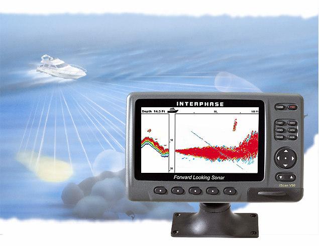
2 To Our Customer: Thank you for choosing the Interphase iscan V90 Forward Scanning Sonar. Throughout the development of this product, we have tried to make sure that we included all of the suggestions made by owners of our earlier sonar models. Selection of features, ease of use, superior performance and outstanding reliability were the benchmarks upon which all important design decisions were made. We feel proud of the iscan V90 and your satisfaction is very important to us. To this end, we welcome any comments or suggestions that you might have in regard to this equipment. It is very important that you complete and return the WARRANTY REGISTRATION CARD within 15 days of purchase so that we have a record of your purchase, both to protect your warranty and to allow us a method to contact you about future enhancements, etc. Sincerely, INTERPHASE TECHNOLOGIES, INC Research Park Drive, #140 Soquel, CA Phone: (831) Fax: (831) comments@interphase-tech.com Website: Interphase iscan V90 is a trademark of Interphase Technologies, Inc Interphase Technologies, Inc. Publication # = V
3 Table Of Contents Important Notice 4 Principle of Operation 5 Display Unit Installation 6 Selecting the Transducer Configuration for your Boat 9 Transducer Installation 10 Getting Started 17 Display Colors/Brightness 18 Set-Up 19 Languages/Units 19 More (Max Vert Gain, Remote/ Master) 19 STC Adjustment 20 Transducer Adjustments 21 Demo 21 System Reset 21 Displays 22 Vertical 22 Down 23 Down Zoom 23 Data 24 Operating Adjustments 25 Range 25 Gain 25 Screen Cursor 26 Scanning Speed 27 Alarm Adjustment 27 Beam Adjustment 27 Video Input 28 Interpreting the Forward Vertical Display 29 Inputs and Outputs 31 Video Inputs 31 External Alarm 31 NMEA inputs (GPS, Temp) / NMEA Depth Output 32 Software Upgrades 32 Remote Displays (2nd Stations) 33 Maintenance 34 Trouble Shooting Tips 34 Interference Problems 35 Specifications 36 How to Obtain Service 37 Warranty 39 3
4 WARNING Navigation based solely on one method or one instrument should never be practiced. While the iscan V90 can be quite useful in showing underwater structure and changing bottom conditions both below and in front of your vessel, there are many situations and conditions which can cause erroneous or distorted readings. In addition, there are many situations that can cause blind spots in the iscan V90 s field of view including the presence of temperature inversion layers (thermoclines), water turbulence, and high concentrations of suspended particles in the water. While the iscan V90 can be considered as a useful aid to navigation, it should never be the only means of navigation. General Information Thank you for your selection of the Interphase iscan V90 Forward Scanning Sonar. The iscan V90 s ruggedly built, compact design makes it ideal for installation on nearly any boat. It will display water depth, bottom conditions and submerged objects such as fish, or objects in your path, on its high resolution display. The iscan V90 is available with either a thru-hull or two transom-mount scanning sonar depth transducers. To ensure that you receive the maximum benefits available from the outstanding features of the Interphase iscan V90, please carefully follow the steps outlined in this manual. An instructive demonstration simulator has been designed into the iscan V90 and we highly recommend that you spend some time using the demo mode prior to actual use of the unit. We also recommend that you read this entire manual before attempting to either install or operate your iscan V90. Warranty Information Interphase provides a limited warranty on the iscan V90 Forward Scanning Sonar which is printed on the inside rear cover of this manual. We recommend that you save all packing materials so that if you should need to send the unit in for repair, it can be fully protected. Should you experience a problem with your iscan V90, first refer to the Troubleshooting section (page 34) of this manual. Most common problems and their solutions are described here. If problems persist, call Interphase Product Support at (831) We will be happy to try to assist you, and if required, we will give you instructions on how to quickly get your set repaired. The enclosed warranty registration card must be completed and returned to Interphase within 15 days of purchase so that your unit may be protected under the warranty. Failure to return the warranty card may cause unnecessary delays in processing your unit for warranty repair. (See warranty, page 39). 4
5 Principle of Operation The iscan V90 Forward Scanning Sonar uses a proprietary and patented phased array acoustic technology first developed for marine use by Interphase Technologies. Known as phased array ultrasound technology, its capabilities have been proven in the military and medical industries for many years. The amazing video images provided by medical ultrasound equipment are familiar to most people and clearly demonstrate the technology s ability to show highly defined images in a "real time" or "live action" mode. Interphase s phased array is a group of piezoelectric ceramic elements that are precisely sized and spaced. Each element can send and receive acoustic pulses. When all elements in the array are sending or receiving acoustic energy at the same time, the entire array behaves like a single larger element with one important difference: the ability of the array to concentrate its acoustic energy in different directions, depending on the different phasing of the signals applied or received by each element. Depending on the signal phasing of the array, acoustic beams can be directed in an almost unlimited number of directions. For example, using an 8 element phased array transducer, the iscan V90 is capable of steering the acoustic beam in any of 60 different directions. Since the acoustic beam in the phased array is steered electronically, requiring no moving parts, it can be quickly and reliably scanned and re-scanned over a large area. When displayed, the changing information between subsequent scans takes on an almost animated quality - for example, showing movement of underwater targets such as fish or rapidly changing bottom conditions. Award Winning Technology For its pioneering work in developing Phased Array Scanning Sonar, Interphase Technologies won the prestigious IMTEC INNOVATION AWARD. The iscan V90 is based on this same award-winning technology. During operation, the iscan V90 converts a small amount of electrical current from your battery into ultrasonic sound pulses, which are then fed to the phased array transducer. These acoustic pulses travel out from the transducer in a cone shaped pattern, called the cone angle. When the sound pulse strikes an underwater object, it is reflected back (echo return), received by the transducer and converted back into small electrical impulses. These impulses are amplified, then displayed as an image on the LCD screen. 5
6 Display Installation iscan V90 Rear Panel Connections Display Unit The compact size of the iscan V90 display unit allows for easy installation in almost any vessel. To get maximum performance and life from your unit, the following guidelines should be considered when selecting a mounting location: 1) Select a location where the unit is protected from excessive temperatures. Heat is one of the worst enemies of electronic components, and will accelerate component aging, thereby reducing the trouble-free life of your iscan V90. 2) Mount the display in a location where it will be convenient to route the power cord and transducer cable. Power connection The iscan V90 s power leads are the red and black wires inside the cable that connects to the rear mount. These wires must be connected to a source of 12VDC voltage. The red wire should connect to the plus (+) 12 VDC and the black wire should be connected to the minus (-) side of the 12 VDC. To minimize electrical interference, carefully route the power cable so that it does not run parallel or close to the transducer cable, engine, refrigeration, bilge pump or any other critical wiring. An in-line fuse holder is included with your unit and should be placed in the positive lead as shown at left. A 2 Amp fuse is included. IMPORTANT: The iscan V90 s 12 VDC power leads should go directly to the boat s battery, distribution board, or breaker panel. Instability of the display may result if the unit has to share leads with other electrical systems aboard your boat. Wiring for Power & Transducer Connectors The correct pin-out wiring sequences for the transducer connectors are shown at right. DO NOT SHORTEN THE TRANSDUCER CABLES. If a transducer cable longer than the 30 length supplied with your unit is needed, please contact your Interphase dealer. A 30-foot scanning sonar transducer extension cable is available. (P/N ) DANGER: Removal of any connector, disassembly of transducer, shortening of any cable or use of any cable other than that supplied by Interphase will void your warranty. Scanning Transducer Input (Green Nut) Power and I/O Cable Video Input 2 Amp In-Line Fuse Blac (-) (+) 12 VDC Red 6
7 In - Dash Mounting The iscan V90 comes with mounting hardware to mount the display in-dash. Four mounting screws and a cutout diagram are included. For in-dash mounting, the mounting base portion of the Quick Disconnect Mount is removed. To remove the mounting base loosen the thumb screw until it seperates from the upper portion of the Quick Disconnect Mount. While the cutout is included, dimensions of the cutout and pilot holes has been included in the drawing below. 8.7 [220mm] 8.3 [211mm] 5 [126mm 3.9 [100mm] Loosen to remove 7
8 Wiring and Cable Connectors 9 Pin Transducer Connectors: (view from front of female plug) Transducer Connections 1 White 1st element 2 Brown 2nd element 3 Orange 3rd element 4 Yellow 4th element 5 Green 5th element 6 Blue 6th element 7 Violet 7th element 8 Gray 8th element 9 Shield Ground/Return 3 Pin Video Input 1 Ground Return VDC 3 Video Signal Transducer Connector Green = Vertical Scanning input Thru-Hull or Transom Mount Transducer Main Power-I/O Wiring. (Cable from Quick Disconnect Bracket) THRU-HULL (T1-I ) TRANSOM MOUNT (T1-I ) QUICK DISCONNECT BRACKET CABLE WIRE COLOR DESCRIPTION FUNCTION BLACK GND/COMMON POWER SUPPLY GND (-) RED POWER VDC POWER SUPPLY (+) WHITE RXA (+) GPS INPUT PORT GREEN RX-TX - GND - SERIAL PORT(s) RETURN YELLOW TXA (+) NMEA OUT/ MASTER-REMOTE/ SOFTWARE DOWNLOADS BROWN RXC (+) NMEA TEMP INPUT PORT GRAY +12 Vdc - OUTPUT 12VDC - FOR ALARM ORANGE RXB (+) MASTER-REMOTE/SOFTWARE DOWNLOADS PINK TXB (+) N/C BLUE TXC - OUTPUT 3+ EXTERNAL ALARM SIGNAL 8
9 Selecting the Transducer Configuration for your Boat Keep in mind the primary rule for transducer operation. This is: the transducer can function as long as it has an unobstructed forward view and has smooth flowing non-aerated water surrounding it. The first line of inquiry should be about the boat. Transom mounted transducers are intended for low speed boats with external props. Boats with inboard motors and boats that regularly exceed 40MPH cannot use transom mounted transducers. Inboard motors create aeration and excess turbulence that prevent the transducers from operating properly. I/O motors where the prop is aft of the transom do not create this situation. Be careful that the driveshaft of the I/O does not block the forward horizontal scan. Boats that exceed 40MPH run a risk of having the transom mounted transduers torn free of the transom. The transom mounted transducers are not designed to be used at these speeds. In addition, the transom mounted transducers are mounted on kick-up brackets. This allows the brackets to kick up at about 35-40MPH. This is intended to allow the transducers to kick-up if they strike an object, or to be pulled up when trailering a boat. Once kicked up, the transducers must be manully reset in order to function. Thru-hull transducers are for boats that exceed 40MPH and /or have inboard motors. Transducer placement depends on boat size, speed, hull configuration and sonar application. On displacement hulls, the transducer is generally located 1/3 aft of where the bow meets the water line. This is the farthest forward the transducer should ever be mounted. It is important that the transducer be below turbulent aerated water created by the bow. Special Thru-Hull Mounting Considerations On sailboats with a fin keel, the transducer is most often placed at the leading edge of the keel and sometimes faired into the keel. As this location may be where the sling rests when hauling the boat, the transducer may be placed on either side of the hull with the foremost face of the transducer even with the leading edge of the keel. Alternatley, the transducer may be placed forward of the keel ahead of the lifting strap location. This should not be ahead of 1/3 aft of where the bow meets the waterline. On planing hulls the transducer is typically placed near the transom. This is to provide smooth flowing water at the greastest speed. However, most planing hull boats create transducer aeration when on plane regardless of transducer location. It should be noted that thru-hull transducers can effect boat performance in two important ways. The first concern is cavitation created by the transducer that causes reduced engine performance by disrupting water flow around the propeller. This is smoothed out by the hull in some boats, but on planing hulls with the transducer near the transom, the hull is not able to clear the cavitation. The second concern is uneven drag on high-speed boats. This may occur when the thru-hull transducer is mounted far off of the centerline of the boat. At low speeds and on large boats the effect is negligible. On smaller boats at high speeds the drag can effect the steering. The effect increases as the boat s speed rises. Boats with trim tabs can usually trim this out, but boats without trim tabs may feel a pulling sensation toward the transducer side of the boat. For this reason it is recommended that the transducer be installed on or close to the centerline of small high speed boats. A less intuative mounting location for the thru-hull transducer on a planing hull is on the centerline just forward of midship. The goal in this mounting is to place the transducer so that it is out of the water at planing speed. As most transducers are aerated at planing speeds, this removes the transducer from the water flow preventing cavitation and steering problems. Most applications for forward scanning sonar occur when the boat is at low non-planing speeds including fishing and navigating hazardous waters. Under these speed conditions the transducer is in the water. Note that the transducer should not operate when it is out of the water. On trailered boats, be certain that the mounting is such that the boat does not rest on the transducers. This could result in damage to the transducer and/or boat hull. Explore possible mounting locations while the boat is on the trailer. 9
10 Transducer Installation Prior to installing the transducer review the Selecting the Transducer Configuration guidelines on Page 9. The iscan V90 comes standard with either a thru-hull or transom mounted forward scanning transducer. It is important to position the transducer so that it has as clear a view as possible of the water directly below and ahead of your boat, as indicated at left. The scanning transducer must be positioned properly so that it scans in the proper direction (i.e. from in front of the boat to the bottom below). The sketch at left shows the proper orientation for both the transom mount and thru-hull transducer. NOTE THAT ON THE TRANSOM MOUNT TRANSDUCERS, THE ROUNDED SIDE MUST POINT FORWARD, AND ON THE THRU-HULL TRANSDUCER, THE MORE BLUNT AREA MUST POINT FORWARD. Side & Front View showing iscan V90 scanning directions. Transom Mounted Transducer General Considerations DO NOT CUT OR SPLICE YOUR PHASED ARRAY TRANSDUCER CABLE OR REMOVE THE 9-PIN CONNECTOR BECAUSE THE SYSTEM PERFORMANCE MAY BE SERIOUSLY DEGRADED. THIS ACTION WILL VOID YOUR WARRANTY. If you need a longer length cable than comes with the transducer (30 ), then purchase the optional 30 extension cables, Interphase Part # It is recommended that only one extension cable length (total of 60 ) be used as additional extensions will decrease the effective power and depth range. Forward Thru-Hull Transducer 1) Choose a location where there is the least amount of acoustic noise, air bubbles or turbulence caused by the boat s movement. The transducer should not be located nearby or especially directly behind the propeller. 2) Choose a location where the transducer can be mounted so that it will be level to the water s surface and will not be tilted to either side. Otherwise the transducer will not scan from the surface ahead to directly beneath the boat. 3) The transducer must always remain submerged, regardless of the speed of the boat and should not be mounted where it could be damaged by underwater obstacles side view Forward Direction top view 10
11 30 Extension Cable 4) DO NOT locate the transducer in the extreme bow of the boat where it will be subject to intense turbulence as the boat pounds through the water. 9-pin Male Interphase Part # Transom Mount Bracket in Released Position 9-pin Female Suggested materials required for installation: Variable speed electric drill with a chuck capacity of 10mm (3/8 ) or larger. Hole saw or spade bit 19 mm (7/8 ) for transom hole to route cable and connector Chamfer bit or 6 mm (1/4 ) drill bit Drill bit No. 28 or 4 mm (9/64 ) Drill bit 3 mm (7/64 ) Marine bedding/sealing compound Note: Will not work at speeds above 35 MPH 5) DO NOT locate the transducer directly behind any hull protrusion which will cause the water to be turbulent when it reaches the transducer or which will obstruct the transducer s forward looking view. For displacement-hull power and sail boats, the thru-hull installation is usually required. DANGER: DO NOT allow any solvents, i.e. gasoline, acetone, to come in contact with the transducer or head unit as this may dissolve the plastic material. DO NOT force the cable by pulling on it. This may cause damage to the internal transducer wiring. Transom Transducer Kick-Up Bracket The transom transducer is attached to the boat with a heavyduty stainless steel kick-up bracket to provide protection against impact. When the transducer strikes an object, or the water force exceeds the resistance of the bracket, the transducer automatically kicks up and becomes nonoperational. The bracket does not automatically reset at lower speeds. The transducer must be manually returned to its operational position. The transducer is designed to kick up at speeds between 35 and 40MPH (30-35 knots). We do not recommend transom mount transducers on boats that regularly exceed 35MPH (30 knots). Boats that exceed 40MPH (35knots) cannot use transom mounted transducers, but instead must use thru-hull transducers. Special Note: The kick-up feature is designed as a safety consideration to prevent the transducer from being removed from the boat due to impact or excessive speed. The kick-up bracket is not designed for repeated kick-up or to be pulled up manually during loading and unloading from boat trailers. Tests have shown that the bracket can kick-up as many as 30 times before there is a negative effect on the bracket. Repeated kick-up will cause the transducer to kick-up at progressively lower speeds. Excessive kick-ups can cause the transducer bracket to fail. Brackets that fail due to repeated kick-up are not covered under the transducer warranty. If the transducer must be kicked up for installation, boat service or loading, the nylok nut on the end of the bracket axle can be loosened. Tighten the nut to 50 inch pounds of torque before operating the boat. 11
12 Kick-up Bracket Replacement Parts If during installation parts are somehow lost are damaged, they can be replaced as follows: Bracket Axle Part# Spray Shield Kit - Includes: Spray Shield, four Mounting Bolts and Nuts, Rubber Grommet and four Large Mounting Screws. Part# Transom Transducer Hardware Kit - Includes: Complete Bracket Axle Assembly and four Large Mounting Screws. Part# Kick-Up Bracket Assembly - Includes: Complete Bracket Axle Assembly, four Large Mounting Screws and the Stainless Steel Mounting Bracket. Nylok Nut Bracket Axle Assembly On some boats it will be neccessary to remove the Bracket Axle during installation. See the diagram to the left and instructions below for details on assembling the axle. 1. Place one stainless steel washer onto the axle against the hex end. 2. Place one small stainless steel spacer against washer. 3. Slide two urethane spacers over the small steel spacer. 4. With the transducer bracket in place, align the long stainless steel spacer with the mounting holes of the mounting bracket and slide the axle in place through the spacer. 5. Place one small stainless steel spacer against the transducer bracket. 6. Slide two urethane spacers over the small steel spacer. 7. Place one stainless steel washer onto the axle against the urethane spacer. 8. Place the nylok nut onto the threaded end of the axle and tighten to 50 inch pounds. If you do not have a torque wrench, tighten until the nut will not turn easily. The stainless steel spacers should prevent over-tightening Transom Mounting Location The main source of vessel acoustic noise is the propeller. It is very important to position the transducer to minimize noise pickup and provide as clear a view as possible of the water ahead of the boat. Study the hull shape of the vessel carefully to determine the best transducer mounting location. To achieve optimal operation the transducer should be mounted in a spot which: * Minimizes acoustic noise reception. * Minimizes the chance that aerated water will flow across the transducer s frontal nose area. Optimizes the transducers view of the area ahead and directly below the boat. 12
13 Transom Mount Locations Cable Transducer The transducer can be installed on either side of an outboard or inboard/outboard engine, or between twin outboards. For single engine installations, normally 18 to 24 outboard of the propeller center line is acceptable and the down stroke side of the propeller is preferred. Choose a location where water flow is smoothest. For dual engine installation, just off the center line is usually acceptable. Because the transducer rotates back and upwards when the bracket releases, it must be mounted in a location where there is sufficient clearance and headroom to allow the full release. Cable 18-24" Attaching the Transducer and Spray Shield to the Bracket Locate the Stainless Spray Shield inside the transducer s stainless mounting ears. Make sure spray shield is orientated as shown in sketch on the bottom left Bracket Axle Rear View Rubber Grommet Fasten Spray Shield with 4 screws & nylok washers as shown Side View Twin Outboards Mounting Bracket Fasten Spray Shield with 4 screws & nylok washers as shown Spray Shield Waterline Transducer must be mounted vertically Then, assemble the stainless kick-up bracket to the transducers using the 4 screws, washers and lock nuts provided. The bracket arms must be mounted outside the stainless steel mounting ears of the transducer. Do not fully tighten the lock nuts at this time. Position the transducer so that it is perpendicular from side to side and make sure the rounded shaped area is pointed towards the front of the boat. Mounting the Transducer to the Boat After you have selected the optimum mounting location and have assembled the mounting bracket to the transducer, mount the bracket onto the hull as shown on the right. Make sure to position the transducer so that it is level in the fore and aft direction and so it will look straight down. Check the location of your boat s waterline and position the flat top surface of the transducer so that it is parallel to the waterline as shown at left. Note: If the transducer is not mounted so that its fore and aft direction is parallel to the surface, then the forward looking display will be distorted and flat bottoms will appear to be slanted upwards or downwards. After mounting the transducer and actually using the iscan V90 on the water, you may need to readjust the transducer s mounting for optimum performance. Spray Shield Waterline Boat Hull 13
14 Thru-Hull Transducer Installation The thru-hull transducer is the recommended choice for larger boats with in-board engines. Thru-hull mounting is usually required on larger power and sail craft in order to find a mounting location free of forward looking hull obstructions. The iscan V90 must have a clear view of the water ahead as it can not magically see through obstructions such as the vessel s hull. Please read the following carefully before starting the thru-hull installation. Normally, thru-hull installations are performed by a professional in a boat haulout facility. We suggest you seek professional assistance before attempting to mount this transducer. Selecting the Best Location The best location to mount the thru-hull transducer will vary with the type of boat. Try to find a location with the smallest dead rise angle to make installation easiest. a. On displacement hulls (sailboats, trawlers, etc.) locate the transducer about 1/3 aft along the waterline. Generally this provides the best compromise between obtaining aeration-free water and minimizing propeller noise. The iscan V90 s transducer can not see through aerated water and water near the bow and near the keel can be quite aerated. Aeration of the transducer can be minimized by keeping the transducer mounted away from the keel and by not mounting too far forward. b. On sailboats, the transducer should be mounted where the acoustic beam will not be shaded by the keel. A spot forward of a fin keel is usually best. Try to find an accessible spot with a minimum dead rise angle. Place the transducer where it will not rest on the lifting strap when hauled. c. On planing powerboat hulls, the transducer should be mounted well aft and close to the keel to insure that the transducer is in contact with the water at higher boat speeds. * On I/O s, transducer mounting close to the engine usually yields good results. * On inboards always mount the transducer well ahead of the propeller(s). Turbulence from props can seriously degrade performance. (Thru-hull installation is recommended.) d. Mount the transducer on the side of the hull where the propeller is moving downwards. The upward motion of the propeller generates pressure waves and pushes bubbles up against the hull. Fin Keel Suggested Thru-Hull Transducer Locations L = waterline length Displacement Hull ~ 1/3 L Planing Hull MOLDED FAIRING BLOCK If you re installation requires a fairing block, you may either have one made locally, or purchase a molded plactic unit from Interphase or your Interphase distributor. For the T1-I Thru-Hull transducer, the molded Fairing Block Part Number is:
15 Mount Transducer so bronze stem is Vertical Waterline DO NOT install a bronze transducer housing directly into an aluminum or steel hull because electrolytic corrosion will occur. Consult your boat-yard for more information on how to properly install transducers into these types of hulls. Hull Transducer Waterline Fairing Block Hull Boat s Hull Keep parallel to waterline! Bronze Hex Nut Forward Keep parallel to waterline! Wood or Plastic Fairing Block (Add sealing compound between faring block & hull) Transducer IMPORTANT: 1) Make sure the water flow across the thru-hull transducer is bubble and turbulence free at all speeds if good performance is to be achieved. 2) Make sure the transducer has an unobstructed view of the water ahead and below the boat. 3) On displacement-hull power boats, the transducer should be mounted relatively close to the center line of the hull. 4) Mount the transducer in a place which has reasonable access from inside the vessel since the transducer s bronze nut will require tightening from inside the hull. Because the iscan V90 scans a 12 degree beam from the surface ahead to directly below the boat, it is important to make sure that the transducer is installed so that it will scan in a vertical direction and not off to either side. The transducer must be mounted so that it s bronze stem is as perpendicular to the water line as possible. If necessary, use a fairing block to properly position the transducer. Use of a Thru-hull Fairing Block Nearly all vessels have some dead rise angle at the transducer mounting location. If the thru-hull transducer were mounted directly to the hull, the sound beam would be tilted off the vertical at the same angle as the dead-rise. Most thru-hull installations will require a fairing block to insure the transducer is mounted properly. A fairing block is typically made of teak, mahogany, or plastic and should be glued between the transducer and hull (both inside and outside) to insure that the transducer s mounting shaft is perpendicular to the water s surface. Make the fairing block as smooth as possible, and not bigger than the transducer s face, to minimize possible turbulence. After cutting the fairing block, trial fit the block to the hull. It is very important that the flat top surface of the transducer be parallel to the water. Because of the skills involved, your professional boatyard provide the fairing block. Installing the Thru-hull Transducer 1) Drill a 1/8 pilot hole from inside the hull to assure access to tighten the housing nut and clearance for the transducer cables. If there is any hull irregularity near the mounting location, it may be desirable to drill from the outside. 15
16 2) Use a 1-1/16 hole saw and drill the hole from the outside of the hull. Sand or clean the area around the hole, inside and outside to insure that the sealing compound will adhere properly to the hull. Select a marine grade adhesive sealant, such as 3M 5200, and use according to the instructions. 3) Remove the bronze hex nut from the housing and cable. 4) Uncoil the transducer cable and thread it through the hole into the inside of the hull. DANGER: DO NOT apply tension to the transducer cables as this may sever internal connections. 5) Apply a 1/8 thick layer of sealant on the upper flat surface of the transducer, bronze alignment pin and fairing block (if used). 6) From the outside of the hull, push the housing into the 1 hole. Twist the housing slightly to squeeze out excess sealant. Carefully confirm that the transducer is aligned so that the round front end is pointed directly toward the front of the boat. 7) Install and tighten the bronze hex nut (allow for swelling in wooden hulls). 8) Remove excess sealant from the outside to assure smooth water flow over the transducer. DANGER: Wood hulls and fairing blocks will expand after the boat is put back into the water, so it is important that the transducer be only hand-tightened until the wood fully expands. Otherwise the wood fairing block may crack. DANGER: Be sure to check for leaks when the boat is placed in the water. Allow at least 24 hours after installation for any leak to appear. DANGER: If the boat is kept in saltwater it is recommended that the transducer be coated with an antifouling paint. USE ONLY WATER BASED ANTI- FOULING PAINT. DO NOT USE KETONE BASED PAINTS. Ketone based anti-fouling paint will attack the plastic materials used in the transducer. See page 34 for recommendations. 16
17 Getting Started CURSR VERT DOWN RANGE PWR VIDEO DATA GAIN ON/OFF - PWR Button. Press the red "PWR" button located at the upper right of the unit to turn the iscan V90 on. The unit will respond with a beep when it turns on. Briefly pressing the PWR button again brings up the menu for adjusting the screen brightness and color. To turn the iscan V90 off, press and hold down the PWR button for longer than 3 seconds. CURSR PWR Soft Keys and Screen Menus The five unmarked buttons below the display are called softkeys (because their use is determined by the menu choices and the iscan V90 s software). Whenever one of the softkey buttons are pressed, or when making adjustments (like changing the color mode, brightness, gain or range) a screen menu will appear at the bottom of the display. For example, the screen menu shown at left is used for selecting the display color mode and adjusting the brightness. Screen Menu VERT DOWN RANGE VIDEO DATA GAIN The screen menu provides visual feedback on the adjustment and often allows further choices by pressing one of the 5 softkeys below the menu. If no button is pressed for several seconds the screen menu will disappear. On some screen menus, the menu will disappear as soon as you make a choice or press the button below the EXIT choice. Note: on some menus, the exit symbol is used instead of the EXIT word. Softkeys NAV Button UP/DOWN Button UP/Down ( ) and NAV Buttons These buttons are often used to make adjustments to increase or decrease something - like the GAIN, RANGE and screen BRIGHTNESS, etc. In several menus you can also use the softkeys below the symbol that appears in the menu to make the adjustment. The button and the symbols on the NAV button have the same function. The symbols on the NAV button are used to select an item in the menu. For example, when the GAIN menu is displayed, the symbol on the NAV key will select the DOWN gain to adjust, while pressing the symbol will select the SCAN gain to adjust. See RANGE/GAIN on page 25 for details. 17

18 Adjust Display Color/Brightness Briefly press the red PWR button when the unit is on, and a menu will appear at the bottom of the display which can be used to select the color mode and the screen brightness. CURSR VERT PWR VIDEO DOWN DATA Three display color modes are available: NORMAL (normal viewing), SUNLIGHT (white background for sunlight viewing) and NIGHT (black background for night viewing). RANGE GAIN A 12-color scale designates the strength or intensity of the returning signal. RED indicates the strongest signal, YELLOW indicates a mid-level return, while LIGHT BLUE returns are the weakest. You can also adjust the display brightness from this menu. If no buttons are touched for 12 seconds the screen menu will disappear. Normal Sunlight Night Down-Brightness-Up Depth 13.2 Ft CURSR PWR VERT VIDEO SET-UP Menu 12.5 DOWN DATA RANGE GAIN Press any of the 5 buttons beneath the display to bring up the softkey menu at the bottom of the display as shown at right Press the button below the SETUP symbol to bring up the SETUP MENU where you can select languages, change the display units, select a boat icon, customize the system gain settings, adjust the NMEA baud rate, set a transducer keel offset, add a compensation for the transducer level adjustment and start/stop the demo mode. For more information about using the SET-UP Menu, please refer to the SET-UP section on pages Scan Speed Beam Adj Video Alarm Set-up DEMO Your iscan V90 includes a built-in DEMO simulator program which makes it easy to practice with the unit and to get a feeling for its many features before actually using it in real situations on the water. To start the DEMO mode, Press any of the 5 buttons beneath the display will bring up the softkey menu. Then press the softkey beneath DEMO. 3 iscan V90 Version KHz EXIT LANGUAGE MORE UNITS DEMO TRANSDUCER CURSR VERT DOWN RANGE PWR VIDEO DATA GAIN 18
19 iscan V90 Version KHz EXIT LANGUAGE MORE UNITS DEMO TRANSDUCER CURSR VERT DOWN RANGE PWR VIDEO DATA GAIN Set-Up The iscan V90 s SET-UP menu allows you to make several important initial settings. Typically, most of these settings are only made once and don t have to be changed. The keel offset adjustment is a good example. The SET- UP menu is shown at left and the following paragraphs describe each choice in detail. English French Spanish German Chinese Korean Greek Danish Ft. Fa. M MPH Km/Hr Knots o F o C Language/Units The iscan V90 allows the choice of several operating languages and conversions for distance, speed and temperature. To select the operating language or choose the unit conversion to use, press the button labeled LANGUAGE/UNITS. A display window as shown at left will pop up on the screen showing the available languages and unit conversions and the ones which are currently selected. Use the softkeys to highlight your desired choice for language, units for range, temp and speed. When finished press the EXIT softkey to save your selection and exit this menu. RANGE DEFAU LT 100 FT MAX G MORE The iscan V90 allows you to customize the maximum possible gain for each range. The table below shows a suggested range of Max Gain settings that you can set. Too much gain on the shallow ranges will cause excess noise and false forward targets. RANGE SUGGESTED MAX GAIN SETTING 0-50 Ft Ft Ft Ft Ft ,200 Ft 31 More - Max Vert Gain, Remote/Master Press the softkey below the MORE choice to bring up a menu to set the MAXIMUM VERTICAL GAIN/range, choose the boat icon, configure the display as either a MASTER or REMOTE or press MORE to adjust the STC to minimize the effect of surface clutter. To choose the boat icon and the MASTER(#1)/ REMOTE(#2) setting, use the softkeys to highlight your choice. To adjust the MAX VERTGAIN*, use the softkey to highlight the desired range - then use the NAV or (UP/DOWN) button to adjust the Max Gain. When finished with all settings, press the EXIT symbol to save your selections and exit the menu. * Note: the Max Vert Gain adjustment applies to the Forward Vertical Scan only. 19
20 STC ADJUSTMENT CURSR PWR The STC Adjustment can be used to help minimize surface clutter problems. Typically, most depthsounders show a band of noise near the surface caused by ringing in the transducer, surface turbulence in the water and other factors. Where there is severe surface clutter, the digital depth display can get confused between showing the true bottom or the surface clutter. In addition, severe surface clutter can cause the alarms to sound. iscan V90 Version KHz EXIT LANGUAGE MORE UNITS DEMO TRANSDUCER VERT DOWN RANGE VIDEO DATA GAIN To minimize these types of problems, the iscan V90 includes an STC Adjustment. STC stands for Surface Time Constant and you can use it to force the iscan V90 to ignore surface clutter. By default, the STC is set to 5 feet - meaning that the digital depth and alarms will ignore anything closer than 5 to the transducer. The clutter will still be displayed, just not used to calculate the digital depth or sound an alarm. RANGE DEFAU LT 100 FT MAX G MORE If you are having problems with the digital depth or alarms because of excessive surface clutter, you can increase or decrease the exclusion range as shown at right. From the SET-UP menu, choose MORE and from that menu choose MORE again. Then press the button below the STC Symbol as shown at right. That will bring up a display showing the STC adjustment line as shown. Use the NAV key to adjust up or down to ignore the clutter area and then press the EXIT symbol to save and return to a normal display. After making this adjustment, the surface clutter will still remain on the display but will be ignored by the alarm and digital depth functions. STC ADJUSTMENT LINE 13.2 Ft CURSR PWR VERT VIDEO DOWN DATA RANGE GAIN
21 Transducer Level (L) and Keel / Depth Offset (K) L = 0 K = 0.0 Set Depth Offset or Keel Offset + If you do not adjust the KEEL or DEPTH OFFSET, the iscan V90 will display depth readings below the transducer. Normally the transducer is mounted at some distance above the bottom of the keel. If this distance is entered as a positive (+) number,( the KEEL OFFSET) the display will show the depth below the keel. The transducer is also mounted below the water line. If this distance is is entered as a negative (-) number, (the DEPTH OFFSET) will show the depth below the water line. The iscan V90 also includes an adjustments to compensate for some transducer installation problems, especially thruhull installations, where the transducer s stem is not perfectly vertical to the water s surface. This problem can be caused by improper installation, or by changes in the boats fore/aft weight. Level Bottom Appears to Slope Upward Level Bottom Appears to Slope Downward Level Bottom Correctly Shown L= -5 K= Ft Adjust +/- 15 degrees When the boat is over a known level bottom, the forward vertical (VERT) scan display should show a level line. If the bottom display is slanted upward or downward (as in the pictures at left), note the approximate angle of the unwanted upward or downward slope on the display. Then proceed to the TRANSDUCER adjustment menu, as above, and press the softkey buttons to adjust the Level (L). It is possible to adjust +/- 15 degrees. Positive numbers will tend to make the bottom slope upwards and negative numbers will make the bottom slope downwards. After making the adjustment, go to the forward vertical display and verify the correction. Once adjusted, the iscan V90 s memory will retain the setting. Demo If the DEMO softkey is pressed the iscan V90 will go into a demonstration mode where simulated data is sent to the display. This mode can be a useful tool to help understand the operation of the unit. To exit the DEMO mode, press the DEMO softkey again. System Reset The iscan V90 remembers most setting when it is turned off. Normally this is good, however sometimes it can cause problems and you may want to do a reset on the machine to restore it to the factory defaults.to do this, turn the unit on while simultaneously pressing both the CURSR and PWR buttons. 21
22 Displays The iscan V90 has three basic display modes which can be accessed directly by pressing one of the four buttons with the display s name. The following paragraphs give a brief description of each of these display modes. More detailed information on how to interpret and make adjustments in these displays can be found in pages 29 to 30 Interpreting your iscan V90 s Display. Depth Bar Current Depth Below Boat Forward Range Vertical Scan Depth 13.2 Ft CURSR PWR Depth Scale VERT VIDEO DOWN DATA Press the button labeled "VERT" to view a full screen forward looking vertical scan display. In this mode, the Iscan V90 scans a 90 degree sector from the surface ahead to the bottom directly below. The resulting display shows the bottom and objects directly in front of the vessel RANGE GAIN The display should look similar to the unit shown at right. The boat icon at the top left of the display represents the position of the vessel. The horizontal line with the scale across the top of the display represents the surface of the water and the vertical scale represents the depth below the vessel. The current depth directly below the boat is shown at the top left of the display - just in front of the boat icon. The current forward range is shown by the digital number at the far top right of the display. This number will change as different ranges are selected. Adjust RANGE/GAIN (see page 25) to optimize the picture. The Depth Bar on the left side provides a visual indication of the depth directly beneath the boat. Adjust in DOWN Mode. 22
23 Press DOWN Once For Split Screen Downlooking AND Forward Scanning Display Down Display Depth Below Boat & Conventional Downlooking Display Forward Range CURSR PWR VERT VIDEO DOWN DATA RANGE GAIN (Conventional down looking) By pressing the DOWN button - once, the iscan V90 s display will split and a conventional downlooking display will appear at the left side of the screen as shown on the right. The downlooking split screen mode will work in either the vertical or horizontal display modes. This down looking display is useful as it shows a history of the bottom depth directly below the boat. The vertical scale just to the right of the downlooking display can be used to determine the depth below the vessel. The current depth is also shown in the large digits at the top left of the display. Adjust the RANGE and GAIN for the best picture (see page 25). Press DOWN Again For Full Screen Downlooking Display To see a full screen downlooking display, press the DOWN button a second time. The display should look similar to that shown on the left. This display shows the recent history of the bottom echos. The most current information is at the right of the screen. DEPTH 13.2 Ft CURSR PWR VERT VIDEO DOWN DATA RANGE GAIN Downlooking Zoom In the full screen downlooking display, you can ZOOM into any 25% portion of the depth being displayed. For example, if the downlooking depth range is 100 feet, then the ZOOM function can be used to look at any 25% of the depth - like 10 to 35 feet, 50 to 75 feet, etc Ft CURSR PWR VERT VIDEO DOWN DATA RANGE GAIN To turn ON the ZOOM feature, press any softkey below the display to bring up the menu shown at left. Then press the softkey under the ZOOM Symbol to bring up a split screen zoom picture as shown at left. The normal depth display is on the left side, while the larger right portion of the display shows the ZOOMED picture. The NAV or UP/Down button can be used to move the ZOOMED area up or down. The ZOOMED area is the area between the two horizontal lines on the normal downlooking display on the left. NORMAL ZOOM VIDEO ALARM SET-UP 23
24 Data Display Press the button labeled DATA and the display will split to show the current depth, speed*, temperature* and Lat/Lon coordinates* in large digits on the left side of the display (see drawing at right) Ft 22.4 KTS CURSR PWR VERT VIDEO DOWN DATA RANGE GAIN 72.6 F 12.5 *In order for the Color Twinscope to show the speed, temperature and Lat/Lon coordinates, the unit must be connected to an NMEA source of this data - such as an active or smart NMEA speed/temp transducer and/or a GPS (for example, the Interphase Chart Master Series) or other acceptable source of NMEA data. Please see NMEA INPUTS on page 32 for more details. 36: N 121:58.05W 25 24
25 Operating Adjustments 13.2 Ft CURSR PWR Range Adjustment DEPTH: 25 FWD RANGE: 50 DEPTH: 25 FWD RANGE: 50 VERT DOWN RANGE VIDEO DATA GAIN Use NAV buttons to change from Depth to Forward Range Adjustment. To change the Depth or Forward Range, press the button labeled RANGE to bring up the Range Adjustment soft key menu. You can use the NAV or UP/DOWN button to adjust the RANGE upwards or downward. If you are in one of the split screen modes with the DOWN looking depth showing on the left, you can adjust the downlooking depth range (Down) and/or the forward looking scanning range. To adjust the downlooking depth range, press the left side of the NAV button to select the DOWN depth adjustment (a red box will indicate it is selected). To adjust the range up or down, use the NAV Button or the UP/DOWN button. To adjust the forward looking Range, use the Right side of the NAV button to select the SCAN range adjustment (a red box will indicate it is selected). To adjust the range up or down, use the NAV button or the UP/DOWN button Ft CURSR PWR When finished, press the EXIT softkey or allow the menu to time-out after a few seconds. VERT VIDEO DOWN DATA 12.5 RANGE GAIN Gain Adjustment (Sentivity) 25 AUTO 31 DOWN AUTO 31 DOWN AUTO 15 SCAN Setting AUTO mode. AUTO 15 SCAN Use NAV buttons to change from Down to Forward Scan Gain Adjustment. Press the button labeled GAIN to bring up the choices available for adjusting the iscan V90's receiver GAIN. Press the button below AUTO so that the word AUTO is shown with a red border if you would like the Color Twinscope to automatically adjust its receiver gain for changing conditions. To manually adjust press the on the NAV or UP/ DOWN button to increase or decrease the receiver gain. Note that the GAIN MENU shows a number which indicates the relative sensitivity being used (+1 to +32). When you choose to manually adjust the GAIN, the Color Twinscope turns off the AUTO mode and it will remain off until the AUTO soft key is again selected. Note: when AUTO mode is turned on the word will be displayed with a red border.. To exit the GAIN MENU and save your adjustments simply press the exit symbol or allow the menu to time-out (approx. 12 seconds) 25
26 Important Note: One of the biggest problems encountered with adjusting forward scanning sonars is too much gain - especially in the vertical forward view. If there are no targets directly in front of the boat, the natural tendency is to continue to increase the gain. Usually this results in a noisy display and is not necessary. In general, if you can see the bottom between 3 and 4 times the depth forward (for example in 10 feet of water, seeing the bottom forward 30 to 40 feet) the gain is adequate. (On forward ranges below 200 feet, it s recommended to keep the gain below the number 10.) 30 to 40 Ft 10 Ft CURSR PWR VERT VIDEO DOWN DATA RANGE GAIN Screen Cursor CURSR PWR VERT VIDEO The iscan V90 has a useful screen cursor feature that can show the approximate depth and range from the vessel to any target on a forward scanning display. Pressing the CURSR button will toggle the screen cursor and it s CURSOR DATA BOX on and off. The drawing at right shows the CURSOR activated and the CURSOR DATA BOX in the lower right corner of the display. DOWN DATA RANGE GAIN Depth 24.5Ft Range 76.0Ft Cursor Cursor Data Box To use the screen Cursor feature, press the CURSR button to activate and then use the NAV button to move the cursor to the desired location on the display. Wherever the cursor is placed, the CURSOR DATA BOX will display the approximate DEPTH and RANGE from the vessel to that location. CURSR PWR VERT VIDEO DOWN DATA RANGE GAIN It is important to realize that the depth information in the CURSOR DATA BOX is the result of a calculation based on the angle of the acoustic beam below the surface of the water. Because each transducer installation is unique and the vessel may be moving up and down in the water - the angle of the acoustic beam is only approximately known. Therefore, the calculated depth is also only an approximation and should not be relied upon during critical situations. It is also important to understand that the calculated depth in the CURSOR DATA BOX is the depth at the center of the Iscan V90 s 12-degree acoustic beam angle as shown in the diagram at right. Notice that the beam expands as it gets further from the boat. For example, at 1,000 feet the beam angle has a diameter of greater than 100 feet! However, the cursor calculates the depth at the centerline of the beam as shown. CURSOR DEPTH AND RANGE 12-Degree Beam Angle Surface Range Depth 24.5Ft Range 76.0Ft Use Nav Key to Move Cursor Depth 26
27 Depth 13.2 Ft CURSR VERT PWR VIDEO Scanning Speed DOWN DATA RANGE GAIN The iscan V90 has two scanning speeds. Fast - indicated with two right facing triangles ( ), and slow, indicated with one right facing triangle(). In the faster mode, the display resolution is reduced because the number of scanning samples is reduced. Alarm Adjustment Scan Speed Beam Adj Video Alarm Set-up A forward looking alarm can be set in the downlooking or the forward vertical scan modes. When the alarm is set, a red alarm line and an alarm depth box appears on the display to indicate the alarm setting and the fact that it is active. Alarm Setting Targets On This Side of Line Will Cause Alarm to Sound In the vertical scan mode, the alarm will sound if a target appears above the alarm line. In the horizontal scan mode, the alarm will sound if a target is closer to the boat than the alarm line. See diagrams at left Depth 13.2 Ft Ft CURSR VERT DOWN RANGE PWR VIDEO DATA GAIN Alarm Line EXIT CLEAR DOWN UP To set the alarm, press any of the five unmarked softkeys below the display to bring up the softkey menu. Then, press the softkey beneath the ALARM symbol to bring up the ALARM MENU. To adjust the alarm setting, use the buttons below the symbols in the ALARM MENU, or the NAV or UP/ DOWN button. Press the softkey button below the EXIT symbol to save the setting and exit, or press the button below the CLEAR symbol to disable the ALARM and exit. CURSR PWR VERT VIDEO DOWN DATA RANGE GAIN Use NAV Button UP/Down to adjust beam sector Beam Adjustment The iscan V90 can scan a 90 degree arc (segment) in a vertical direction. In some cases you may want to reduce the size of the sector and then steer it in a particular direction. Reducing the sector size is one way to increase the scanning speed, as time isn t spent scanning unwated areas. EXIT CLEAR To adjust the beam, press any of the five unmarked softkeys below the display to bring up the softkey menu and thenpress the softkey beneath the BEAM symbol to bring up the BEAM MENU. 27
 the BEAM adjustment and exit.")
28 Use the NAV or UP/DOWN buttons to adjust the beam sector width and then use the NAV left/right buttons to steer the resulting sector toward the surface or toward the bottom. Press the softkey button below the EXIT symbol to save the setting and exit, or press the button below the CLEAR symbol to disable (reset) the BEAM adjustment and exit. CURSR VERT DOWN RANGE PWR VIDEO DATA GAIN A good example of the use of the beam adjustment is when cruising in deep water where the desired scanning area is close to the surface (looking for obstructions, etc). In this situation you could reduce the size of the scanning sector and then steer it up to the surface. This would result in the desired coverage but with a much faster scanning speed. See diagram at bottom of previous page. Use NAV buttons to steer beam sector Video Inputs The iscan V90 has a 3-pin video input connector on the rear panel. You can connect video cameras, VCR, DVD and other sources of NTSC OR PAL signals to this connector and view them in a full-screen format on the iscan V90 s display. If more than one camera or video input is required, you can use a video switch to choose between several video signals. Pressing the softkey button marked VIDEO will switch the video signal to the display. When the VIDEO selection is ON, pressing any of the 5 bottom softkey buttons will turn it OFF and the display will return to the sonar mode. Pressing the softkey button below the Video selection will also swith the unit to the Video display. Pressing any of the bottom 5 softkeys will turn it off and return the display to the sonar mode. Interphase View Cam Color CCD camera. Water-resistant. Complete with 30 cable. (P/N # ) 13.2 Ft 22.4 KTS 72.6 F : N 121:58.05W CURSR VERT DOWN RANGE PWR VIDEO DATA GAIN Interphase FishCam Color CCD camera. Waterproof face. Designed to fit in thru-hull fitting. Complete with 30 cable (P/N # ) Thur-Hull Housing Kit (P/N # ) Blanking Plug for above (P/N # ) 28

29 Weak Return From Far-Forward Strong Return from Up-sloping Bottom Strong Return from Wall Far-Forward Interpreting The Forward Vertical Display The Interphase iscan V90 provides a display which shows acoustic echo returns from the underwater area beneath and ahead of the vessel. The Phased Array Transducer steers an acoustic beam over an arc which can be adjusted from approximately 12 to 90 degrees. As the iscan V90 steers the beam to different positions, it transmits a pulse of energy and then waits a defined period of time (depending on the range selected) and listens for any return echoes. As the energy from this acoustic beam strikes underwater objects or the bottom, a small portion of the energy is reflected as an echo back to the transducer. When the echo is received at the transducer, it s converted into a small electrical signal, processed and displayed on the iscan V90 s LCD. The unit knows the direction in which it sent the transmit pulse and the time it took to receive the return echo, so it can determine the location of the object or bottom that created the return echo. As the iscan V90 sequentially steps the acoustic beam from directly forward to the bottom, the LCD display shows a continuously updated display of the return echoes in their approximate position in relation to the vessel. Because the LCD display is only showing the acoustic echoes that are returned to the transducer, it can not show forward bottom conditions that are hidden from its field of view or are hidden due to obstructions in the acoustic beam s path through the water. In addition, smooth bottom conditions far forward of the vessel are difficult to see as very little of the acoustic energy is reflected back as an echo. See the sketch at left. Bottoms that are rough and rocky or are sloping upwards will reflect more acoustic energy back to the transducer and will show up better far-forward of the vessel than bottoms that are very smooth or slope downward. However, even though the bottom may be smooth and does not show up far forward, large obstructions (sea wall, large rocks, underwater shelves, etc.) will typically send back strong echoes that can be seen far forward, as the sketch at left indicates. Distance Forward Under typical conditions, the iscan V90 will show level or shallowing bottom contours for a distance forward of between 3X to 5X the depth below the transducer. Obstructions in the water, such as walls, mud banks, etc. may be seen at greater distances, subject to the depth below the transducer and the 1,200 ft. maximum forward range. 29
30 Besides the bottom conditions, water conditions will also affect the iscan V90 s performance. For example, surface chop, temperature inversion layers (thermoclines) and muddy water may degrade performance. Noise and Sensitivity Adjustments The iscan V90 features an AUTO gain feature where it continuously adjusts the gain to achieve the optimum picture quality. The gain can also be adjusted manually to allow for a reduction in gain to minimize the effect of screen noise, or to increase the gain to show weaker targets. In the forward scanning modes, the gain setting is especially important as too little gain will cause a loss of far forward bottom readings and too much gain will cause an increase in screen noise and a possible display of unwanted transducer sidelobe readings. Transducer Sidelobe Effect The iscan V90 s transducer, like all acoustic transducers, does not form a perfect beam of acoustic energy. Some of the acoustic energy is contained in an area called the sidelobes. In conventional downlooking depthsounders, the sidelobes create little problem except to distort the size of the actual beam angle; however, in scanning sonars they can create echoes that are not placed on the LCD screen in their proper position (also known as false echoes). As the iscan V90 sends off its acoustic beam in a specific direction, it assumes that any return echoes are within the main beam. However, if the sidelobe energy (which is not within the main beam) strikes a large object (i.e. the bottom) and creates a strong return echo, the iscan V90 has no way of knowing that this false echo was not created by the main beam and will go ahead and show it on the display as if it was located within the main beam. The most typical display of the sidelobe echoes appears as an arc at the same distance as the bottom depth, and in the worst case, from the bottom below to the surface ahead. After using the iscan V90 in different situations, with different gain settings, you should become proficient in identifying the bottom echoes caused by the transducer s sidelobes. To minimize the sidelobe effect, the gain should be reduced. False Echoes Transducer Sidelobes Main Beam Sidelobe Main Beam False Bottom Echoes Caused by Sidelobe Returns. 30
31 Inputs and Outputs Pin 1= Ground Return Pin 2 = +12 Vdc Pin 3 = Video Signal Video Input A 3-pin connector on the rear of the iscan V90 will accept NTSC or PAL video signals from cameras, VCRs, DVDs and other common video sources. When the Video mode is choosen the iscan V90 s LCD display will show the video input in a full screen format. It is not possible to split the screen in the video mode.. The sketch at left shows the wiring of the 3-pin rear panel connector. View Cam # Fish Cam # The 3-pin connector supplies 12 Vdc at a maximum of 100mA to power an external camera. It s important that the camera not draw more than 100mA or it could cause permanent damage to the iscan V90 s power supply. Interphase offers two color cameras which can be easily connected to the iscan V90; the View Cam and the Fish Cam. The View Cam is splash proof and is ideal formounting in engine rooms, or to monitor deck areas. The View Cam is designed to fit into a plastic thru-hull and has a waterproof face. It s ideal for underwater viewing. External Alarm A loud remote alarm can be connected to the iscan V90 which will sound when the depth or range alarm is triggered. The external beeper alarm can be connected between the BLUE and the GRAY wires on the main power and I/O cable from the Quick Disconnect. The alarm should be a piezo beeper type and the current consumption should not exceed 20 ma. Interphase offers a piezo-beeper alarm which we have found to be loud and reliable. Please call us at (831) , ext. 16 for more information. Part# Gray (+12V) Blue External Alarm 31
32 CURSR VERT DOWN RANGE PWR VIDEO DATA GAIN NMEA Inputs (Position, Speed & Temp) The iscan V90 has two independent serial NMEA input ports. One can be used to connect to a source of lat/lon position and speed data (i.e., GPS), and the other can be connected to a source of temperature and speed data. An external GPS should be connected between the White(+) and Green(-) wires in the power and I/O cable from the Quick Disconnect Mount, and the Temperature and Speed source should be connected between the Brown(+) and Green(-) wires. The iscan V90 looks for the following NMEA sentences for position, speed and temperature. GLL ( Lat/Lon Postion) VTG (Speed over the ground) MTW (Temperature) NMEA Depth Output NMEA 0183 depth information is sent out on the Yellow(+) and Green(-) wires. See the sketch at right showing the wiring for the NMEA output port. White(+) Green(-) Brown(+) Yellow (+) Green (-) GPS (Lat/Lon & Speed) TEMP NMEA DEPTH OUTPUT The iscan V90 sends out the following NMEA 0183 sentences with the digital depth data Ft DPT, DBT 22.4 KTS 72.6 F 12.5 Software Upgrades 36: N 121:58.05W 25 You can download software updates to your PC from our website at and then upload the new software to your iscan V90 by using the PC Software Upgrade Cable (P/N# ). Check out the Interphase Website for future iscan V90 software upgrades. To get a PC Software Upgrade Cable, please call Interphase at (831) , extension 16. Mini-USB Port 6 Foot Mini-USB - B to USB - A cable Part# Connect the Mini-USB connector to the port under the rubber protective cover on the front bottom right corner of the iscan V90. Connect the other end of the cable to the USB port of your PC. Note: Detailed upgrade instructions are available on our website at 32
33 Remote (2nd Station) Connections REMOTE UNIT #2 Remote Display The iscan V90 can operate with two displays: one being designated as the Master (#1) and the other as the Remote (#2). The transducer cables connect to the Master (#1) unit and the signal is automatically switched between the Master (#1) and the Remote(#2) during operation. 30 Remote Cable # Length of 3-Conductor Wire MASTER UNIT #1 TRANSDUCER (connects to Master Unit) ORANGE YELLOW GREEN ORANGE YELLOW GREEN The normal iscan V90 will operate as a stand-alone unit or as a Remote unit in a two display installation, but can not operate as a Master unit. The iscan V90 Remote Kit includes a 30 Remote Cable (P/N ) that carries the sonar information from the transducer between the two displays. It should be connected between the extra 9-pin connector on the rear of the Master(#1) unit and the 9-pin GREEN input connector on the Remote (#2) unit. In addition, the two units need to be connected via their serial ports with a three wire cable as shown on the sketch on the left. Note that the Orange wire from the Master (#1) connects to the Yellow wire from the Remote (#2) and the Yellow wire from the Master (#1) connects to the Orange wire from the Remote (#2). The Green wires from both units are tied together. Once connected, you will need to go into the SETUP menu of each unit and set the standard unit up as a REMOTE (#2) and the other unit unit (the one included with the REMOTE STATION KIT with two 9-pin connectors on the rear) as the MASTER(#1) unit. See page 19 for details. In a two-station system, the Master (#1) must always be turned on. Then, if the Remote PWR button is pressed, the Master (#1) display will go into a standby mode while the Remote (#2) is being used. To re-activate the Master (#1) station, the Master Display PWR button needs to be briefly pressed. (pressing for more than a few seconds will turn the Master off). If the Master (#1) is turned off, for any reason, both displays will not function. 33
34 Maintenance Below are some helpful tips for keeping your iscan V90 in top condition: 1) Keep your display clean and dry. Occasionally wipe unit off with a damp cloth, but be careful not to scratch the lens covering the LCD screen. For stubborn dirt, use a mild soap and a damp cloth. NEVER USE SOLVENTS SUCH AS PAINT THINNER, ACETONE, OR GASOLINE TO CLEAN YOUR UNIT. 2) Occasionally clean the face of the depth transducer (sensing surface) and carefully remove any marine growth. Use a mild detergent, or 220 grit sandpaper, or crocus cloth to remove stubborn growth. 3) If the in-line fuse is blown, replace it with a 2 amp fuse. NEVER REPLACE WITH A HIGHER AMP RATING! If the fuse continues to blow, check the polarity of your 12 VDC power source. If the polarity is correct, check with the Technical Service Department at (831) ) In order to protect your transducer from water damage, paint it with one of the following brands: Interlux- UltraCoat, Fiberglass Bottom Coat, Super Bottom Coat; Pettit-UniPoxy; Rule-Super KL, Gloss Dura Poxy. DO NOT use a solvent based paint. 5) DO NOT allow any solvents, i.e. gasoline, acetone, to come in contact with the transducer or head unit as these may dissolve the material. Troubleshooting Tips PROBLEM Unit will not turn on, or unit beeps but no picture appears. Unit blows fuses. Loses picture at speed. Screen is full of noise, or has dots running through. LCD darkens in sunlight after prolonged use. Bottom slopes up/down. Digital water depth not working. Controls do not respond. Unit will not change operating modes. POSSIBLE SOLUTION Check fuse, battery voltage and power connections. Check your connections to the battery. Wiring is reversed or there is excessive current from the battery. 2 amp fuse required. Adjust the transducer angle or placement. Make sure that the transducer is installed in the area which has the least amount of water turbulence. Reduce gain setting. Review the section on interference. Check to see if other 200khz sounders are nearby. Overexposed to sunlight - provide shading for display. Adjust the transducer angle or adjust the level setting. Increase your gain, and check that you can see the bottom in the DOWN mode. Perform FACTORY RESET: Start with the unit off. Press and hold down the POWER and CURSOR keys. One the unit powers up, it is reset to the factory settings. 34
35 Interference Problems Interference can come from several sources. The most common of these are: 1) Other nearby depth sounders operating at the same frequency. 2) Radiated interference from the boat s electrical system (alternator, distributor and spark plugs) or from nearby equipment that radiates electrical noise. 3) Conducted interference usually occurs when the iscan V90 shares a 12VDC power lead with other noisy equipment (i.e.; bilge pumps, motors, refrigeration systems, autopilots, etc.) Interference caused by nearby depth sounders operating on or near the same frequency as the iscan V90 will typically appear as rabbit tracks that march up and down the screen. Reducing the gain will help minimize this problem. Radiated interference caused by the boat s engine can usually be identified by observing the iscan V90 with both the engine running and turned off. If the interference disappears when the engine is turned off, it is safe to assume that the engine is the source of the interference. This type of interference can usually be eliminated by using the same techniques used in the automotive industry to eliminate interference to car radios, CB s, etc. The following actions may be required: 1) Reduce the Gain setting to minimize interference. 2) Make sure your boat uses resistor type spark plugs and plug wiring. 3) Install a suppressor on the center lead of the distributor. 4) Install an alternator filter to smooth the alternator s output signal. Interference may also be caused by radiation from other nearby equipment and can be detected by turning off all other equipment and observing the iscan V90 s display as each suspected source is turned back on. This type of interference can usually be eliminated by moving the iscan V90 away from the source and checking to ensure that the interfering source is properly grounded. Interference causing the display to be unstable, to pulsate or periodically change size is usually caused when another piece of equipment shares the same 12 VDC power leads from the battery. This problem is especially severe when equipment requiring large current surges (i.e.; autopilots, refrigerators, or bilge pumps) share the same power leads. Minimize this type of interference by running the iscan V90 s 12VDC power leads, or those of the interfering equipment, directly to the battery. Alternately, you may find it helpful to install a separate dedicated power supply battery that is used only to run your electronic gear (e.g.; fishfinders, VHF radios, radar units, etc.). If your unit shuts off during low voltage situations, such as when cranking your engine starter, you may want to install an isolator switch with an A/B type of battery system. An A/B system allows you to run your electronic gear on one battery, while the starter and alternator are hooked up to the other battery. Your authorized marine electronics dealer is familiar with the methods of reducing electrical interference and is qualified to assist you should a problem persist. 35

 NMEA 0183 Inputs: NMEA 0183 Output Dimensions: Standard Equipment: GLL, VTG, MTW DBT, DPT 9.5 W x 5.9 H x 3.")
36 Specifications Transom Transducer Part # T1-I Thru-Hull Transducer Part # T1-I Display Type: Depth Ranges: Forward Ranges: Transmit Frequency: Transmite Power: Transmit Beam Angle: Pulselength and Sounding Rates: Power Requirements: 480 x 234 pixels, Sunlight Color Active Matrix LCD Depth ranges, 0-25 to 0-600feet Forward ranges, 0-50 to 0-1,200 feet 200 khz Approx. 450 RMS or 3,600 peak-to-peak Watts Approx. 12 degrees Automatically optimized for selected range. 11 to 16 VDC, less than 1.2Amp. Operating Temperature: 0 to 50 degrees C (32 to 122 degrees F) NMEA 0183 Inputs: NMEA 0183 Output Dimensions: Standard Equipment: GLL, VTG, MTW DBT, DPT 9.5 W x 5.9 H x 3.25 D Display with protective cover, Quick Disconnect Mounting Bracket with Power/IO cable, in-line fuse, operation manual and depth transducer with 30 cable. 36
37 How to Obtain Service If you feel your set is not operating properly, first refer to the sections of this manual on Troubleshooting and Interference Problems. This information solves the most common problems. If problems persist, please call Interphase Technical Service at (831) Ext: 16 or send your unit in with the information below filled out. If you do need to return your set, send it to the following address: Service Department Interphase Technologies, Inc Research Park Drive, Suite 140 Soquel, CA In addition, to speed your repair please fill out the following, tear this page out of the manual (or photocopy it), and tape it to your unit for our technicians to review. A copy of your purchase receipt must be included to verify the purchase date. RETURN TO: (Your Name) (Street Address - No P.O. Boxes Please) (City) (State) (Zip) Daytime Telephone: ( ) Evening Telephone: ( ) Address: Model: iscan V90 Serial #: Purchase Date / / Type of transducer: Transom mount Thru-Hull Other Please describe the problems you are having with the unit in as much detail as possible in the space below. Please use another sheet of paper if necessary. 37
38 Notes 38
39 Interphase Technologies, Inc. 5 Year Limited Warranty Any unit that fails during the first year of the warranty period will, at Interphase option, be repaired or replaced at no charge to the customer provided it is returned to Interphase, freight prepaid with proof of date of purchase and a description of the malfunction. Repair or replacement during the warranty period will not extend the basic warranty period. From the second through the fifth year, Interphase will, at its option, repair or replace defective units for a fixed fee. This fee will be set at the beginning of each year. More information about the fixed rate repair fee is available by calling Interphase at (831) or visit our website at: This warranty does not apply to an Interphase product that has failed due to improper installation, misuse, or accident, nor does it apply to products which have been repaired or altered outside the Interphase factory. Transducers, GPS antennas and Radar Antennas are subject to extreme conditions beyond control of the manufacturer and Interphase. Due to these conditions, the warranty on these components is limited to one year against defects in workmanship or materials. The fixed fee for years two through five of the warranty does not apply to these components. Any costs incurred with transducer or antenna replacement are specifically excluded from this warranty other than the cost of the components themselves. This warranty does not include incidental or consequential damages and Interphase disclaims any liability for any such damages. All implied warranties, if any, are limited in duration to the above stated one year warranty period. Some states and provinces do not allow the exclusion or limitation of incidental or consequential damages, therefore, the above limitations may not apply to you. The completion and return of the enclosed Warranty Registration Card is a condition precedent to the warranty coverage. Owner must provide proof of date of purchase in order for warranty to be valid. This warranty gives you specific legal rights which may vary from state to state and province to province. This warranty is limited only to the original purchaser of the unit. 39

40 2880 Research Park Dr Suite #140 Soquel, CA PHONE: FAX:
Owner s Manual. Dual Station Operation. DS41 Digital Depth Sounder
 DS41 Digital Depth Sounder Owner s Manual Standard 2 Inch Installation Dual Station Operation NMEA Repeater Reads in Feet Fathoms or Meters Adjustable Prop or Surface Offset Shallow and Deep alarms Dual
OWNER S GUIDE & INSTALLATION INSTRUCTIONS
 OWNER S GUIDE & INSTALLATION INSTRUCTIONS Sealcast and Cast Resin Transducers Record the information found on the tag for future reference. Part No. Date Frequency khz with Airmar Fairings Models: M155,
PIRANHA I & 2 INSTALL GUIDE
 TOP Use 5/32" drill bit DO NOT LET DEADRISE INTERSECT THIS LINE PLACE EITHER CORNER ON DEADRISE ANGLE PIRANHA I & 2 INSTALL GUIDE Two components need to be installed on the boat: the transducer and the
OWNER S GUIDE & INSTALLATION INSTRUCTIONS
 OWNER S GUIDE & INSTALLATION INSTRUCTIONS IMPORTANT: Please read the instructions completely before proceeding with the installation. These instructions supersede any other instructions in your instrument
PIRANHA I & 2 INSTALL GUIDE
 PIRANHA I & 2 INSTALL GUIDE Two components need to be installed on the boat: the transducer and the control head. The control head displays sonar information, the transducer sends and receives sonar signals
Thru-Hull TRIDUCER Multisensor with Strap
 OWNER S GUIDE Thru-Hull TRIDUCER Multisensor with Strap Models: B66V, B66VL, B744V, B744VL & INSTALLATION INSTRUCTIONS Record the information found on the cable tag for future reference. Part No. Date
TRIDUCER Multisensor with Valve & Pin
 INSTALLATION INSTRUCTIONS TRIDUCER Multisensor with Valve & Pin Models: B744V, B744VL, B66V, B66VL 17-118-02 rev. 02 04/12/11 IMPORTANT: Please read the instructions completely before proceeding with the
NX Combi Transducer. Installation and Operation Manual English
 NX Combi Transducer Installation and Operation Manual Start pack 3 1 Start pack 3 Edition: April 2007 2 Start pack 3 1 Registration... 3 2 Installation... 4 3 Mounting of Transom transducer... 4 3.1 Applications...
PIRANHA 5 INSTALLATION GUIDE
 PIRANHA 5 INSTALLATION GUIDE Two components need to be installed on the boat: the transducer and the control head. The control head displays sonar information, the transducer sends and receives sonar signals
Installation. minnkot amot or s.com
 Installation minnkot amot or s.com INSTALLATION Your Talon comes complete with the items listed below. Please take a moment to familiarize yourself with the parts list and tools needed prior to starting
NX Tri Ducer. Installation and Operation Manual English
 NX Tri Ducer Installation and Operation Manual NX TRI-Ducer 1 NX TRI-Ducer Edition: April 2007 2 NX TRI-Ducer Mounting instruction Tri-transducer 1 General... 3 1.1 Tools and Materials... 3 1.2 Pre-Installation
OWNER S GUIDE & INSTALLATION INSTRUCTIONS
 17-247-03 rev. 06 08/23/17 OWNER S GUIDE & INSTALLATION INSTRUCTIONS Transom-Mount with Integrated Release racket Depth Transducer or TRIDUCER Multisensor Models: P66, P66S Smart Sensor Patents apply to
Panoptix PS21-TR. Installation Instructions. Important Safety Information. Registering Your Device
 Panoptix PS21-TR Installation Instructions Important Safety Information WARNING See the Important Safety and Product Information guide in the chartplotter or fishfinder product box for product warnings
AUTO GLIDE INSTALLATION GUIDE MANUAL A
 GLIDE INSTALLATION GUIDE MANUAL A TABLE OF CONTENTS.0 PRODUCT OVERVIEW 3-4. System Requirements 4.0 GLIDE MECHANICAL INSTALLATION 5-6. Auto Glide Key Pad Installation. Replacing Existing 3 LED Indicator
Owner s Manual And Guide To Installation
 Owner s Manual And Guide To Installation < # > TABLE OF CONTENTS 1 How to Use...3 1.1 Control Keypad...3 1.2 Mounting Hardware...4 1.3 Auto Launch Details...5 1.4 Trailering with the SWITCHBLADE...6 1.5
CAUTION WARNING. Heading Sensor Assembly HEADING SENSOR FUNCTIONS THEORY OF OPERATION MOUNTING CONSIDERATIONS
 Heading Sensor Assembly 2996400 COMPATIBLE WITH ALL BLUETOOTH ENABLED i-pilot AND i-pilot LINK TM SYSTEMS Item / Assembly Part # Description Qty. A 2996400 HEADING SENSOR ASSEMBLY 2393400 SCREW-#8-8X-/2
TABLE OF CONTENTS. 1 How to Use Control gauge and Rocker Switch Mounting Hardware... 3
 1 TABLE OF CONTENTS 1 How to Use.... 3 1.1 Control gauge and Rocker Switch... 3 1.2 Mounting Hardware.... 3 1.3Trailering with the SWITCHBLADE... 4 1.4 Maintaining your SWITCHBLADE... 4 2 INSTALLATION
INSTALLATION PREPARATION
 PARTS SUPPLIED INSTALLATION PREPARATION PARTS SUPPLIED Before installing your new Humminbird fishsinder, please ensure the following parts are included in the box: Fishfinder Transducer with 20 (6m) of
OWNER S GUIDE & INSTALLATION INSTRUCTIONS
 17-284-01 rev. 06 02/01/18 OWNER S GUIDE & INSTALLATION INSTRUCTIONS Thru-Hull: Flush, Long, Retractable Smart Sensor Depth Transducer: B122 TRIDUCER Multisensor: DST800L Patents apply to DST800L. US Pat:
Single Colour Light. TIX301 Interchangeable Flush Fit Thru-Hull Light. Installation and Operation Guide
 Single Colour Light TIX301 Interchangeable Flush Fit Thru-Hull Light Installation and Operation Guide Congratulations! You have purchased a LUMISHORE advanced technology LED underwater light. Every care
Sea Water Temperature Gauge
 SST-110 I Sea Water Temperature Gauge Table of Contents Introduction............................ 3 Installation..............................5 Operation...............................7 Key Functions...........................
OWNER S GUIDE & INSTALLATION INSTRUCTIONS
 OWNER S GUIDE & INSTALLATION INSTRUCTIONS 17-572-01 rev.03 07/24/18 Thru-Hull: Retractable with Valve Ultrasonic Speed & Temperature Smart Sensor Models: UST800, UST850 Follow the precautions below for
Single Colour Light. TIX202 Interchangeable Flush Fit Thru-Hull Light. Installation and Operation Guide. Rev
 Single Colour Light TIX202 Interchangeable Flush Fit Thru-Hull Light Installation and Operation Guide Rev 3 45-0038 Congratulations! You have purchased a LUMISHORE advanced technology LED underwater light.
Sprayer Control. Manual for SprayLink Cable Installations. Tank. Jet Agitator. Agitator Valve. Diaphragm Pump. Pressure Transducer.
 Sprayer Control Plumbing & Installation Manual for SprayLink Cable Installations Tank Jet Tank Shut-Off Diaphragm Pump Electric Ball s Transducer Strainer Relief Regulating Copyrights 2012 TeeJet Technologies.
INSTALLATION PREPARATION
 INSTALLATION PREPARATION PARTS SUPPLIED PARTS SUPPLIED Before installing your new Humminbird fishfinder, please ensure the following parts are included in the box: Fishfinder Transducer with 20 (6m) of
Trolling Motor 360 Imaging Installation Guide _B
 Trolling Motor 360 Imaging Installation Guide 532178-2_B Thank You! Thank you for choosing Humminbird, the #1 name in marine electronics. Humminbird has built its reputation by designing and manufacturing
Digital Depth Sounder Display Installation and Operation Manual IMPORTANT
 DF1120S Digital Depth Sounder Display Installation and Operation Manual WARNING!!!! This depth sounder is an indicator of the water depth underneath the vessel; NOT A DEPICTION OF THE DEPTH AHEAD OF THE
TIX402 EOS Installation and Operating Guide
 TIX402 EOS Integrated System TIX402 EOS Installation and Operating Guide Congratulations! You have purchased a LUMISHORE advanced LED technology underwater lighting system. Every care has been taken to
X-4. Fish-Finding Sonar. Installation and Operation Instructions
 X-4 Fish-Finding Sonar Installation and Operation Instructions Copyright 2010 Navico All rights reserved. No part of this manual may be copied, reproduced, republished, transmitted or distributed for any
GHP 12 Installation Instructions
 GHP 12 Installation Instructions To obtain the best possible performance and to avoid damage to your boat, install the Garmin GHP 12 marine autopilot system according to the following instructions. Professional
INSTALLATION PREPARATION
 INSTALLATION PREPARATION PARTS SUPPLIED PARTS SUPPLIED Before installing your new Humminbird fishfinder, please ensure the following parts are included in the box: Fishfinder Transducer with 20 (6m) of
SR MARINER SELF POWERED KNOTMETERS
 SR MARINER SELF POWERED KNOTMETERS INSTALLATION INSTRUCTIONS Congratulations in choosing a high performance marine instrument and welcome to the growing family of SR Mariner product owners. Since our establishment
ENSURE THAT THE TEMP PROBE FITS YOUR OUTDRIVE BEFORE BEGINNING INSTALLATION.
 715 Center Street Grayslake IL 60030 P: 847-752-2700 F: 847-752-2415 E: info@livorsi.com Drive temp gauge installation instructions Model Number: DCSDT (color) The Livorsi drive temp gauge kit easily installs
OWNER S GUIDE & INSTALLATION INSTRUCTIONS
 OWNER S GUIDE & INSTALLATION INSTRUCTIONS 17-259-01 rev. 03 07/31/18 Thru-Hull: Retractable with Valve Ultrasonic Speed & Temperature Sensor Smart Sensor Model: CS4500 Patent http://www.airmar.com/patent.html
UltraSystem Series II INSTALLATION MANUAL PARTNERED WITH
 UltraSystem Series II INSTALLATION MANUAL PARTNERED WITH CONTENTS Important information. page 1 Planning the installation. page 2 Transducer positioning. page 3-7 Transducer installation. page 8-10 Control
INSTALLATION MANUAL. Power-Pole Blade Edition Shallow Water Anchor. Installation Instructions
 INSTALLATION MANUAL Power-Pole Blade Edition Shallow Water Anchor Installation Instructions CAUTION: Read this instruction manual carefully. Become familiar with the controls and know how to operate the
LDT Digital Temperature Gauge. Installation & Operation Instructions
 Pub. 988-0099-071 LDT-3200 Digital Temperature Gauge Installation & Operation Instructions The LDT-3200 combines a temperature gauge, voltmeter and clock in one housing. It displays the temperature in
Marine Product Selection Guide Transducers, Instruments and Sensors
 Marine Product Selection Guide Transducers, Instruments and s Garmin.com/marine Garmin International, Inc. East 151st Street, Olathe, KS 66062 p: 913.7.0 f: 913.7.22 Garmin Corporation. 6, Jangshu 2nd
Thru-Hull, Retractable with Valve Ultrasonic Speed & Temperature Sensor
 OWNER S GUIDE Thru-Hull, Retractable with Valve Ultrasonic Speed & Temperature Sensor & INSTALLATION INSTRUCTIONS Record the information found on the cable tag for future reference. Part No. Date 17-259-01
Do isolate the power supply from other high power systems such as Stereos and Alarms
 Thank you for purchasing a Smart Ride Air Management System, AIRBAGIT.COM s premier flagship product. This system will meet all of your custom and utility needs and will provide you years of trouble free
INSTALLATION GUIDE DYNAMIC TRIM CONTROL SYSTEM SERIES S
 INSTALLATION GUIDE DYNAMIC TRIM CONTROL SYSTEM SERIES S TOOLS Power drill Drill bits Hole saw Screw bits Ø 2.5 mm (3/32 ) Ø 3 mm (1/8 ) Ø 3.5 mm (9/64 ) Ø 4 mm (5/32 ) Ø 5 mm (3/16 ) Sealant Ø 19 mm (3/4
FLEXI-COIL 67 Series (1999+) Installation Manual FC1
 Installation Manual FC1") FC1 FLEXI-COIL 67 Series (1999+) Installation Manual Printed in Canada Copyright 2012 by NORAC Systems International Inc. Reorder P/N: UC4.5-BC-FC1-INST Rev C (FLEXI-COIL 67 Series (1999+)) NOTICE: NORAC
FC1 FLEXI-COIL 67 Series (1999+) Installation Manual Printed in Canada Copyright 2012 by NORAC Systems International Inc. Reorder P/N: UC4.5-BC-FC1-INST Rev C (FLEXI-COIL 67 Series (1999+)) NOTICE: NORAC
Solid-State Compass with GPS Receiver
 Owner s Guide & Installation Instructions Solid-State Compass with GPS Receiver Model GH2183 Record the serial number found on the sensor. Serial No. Date of Purchase 17-489-01 rev. 01 04/22/08 1 WARNING
Wireless Tire Pressure and Temperature Monitoring System Instruction Manual Model #: TM Cap Sensors
 Wireless Tire Pressure and Temperature Monitoring System Instruction Manual Model #: TM-510 510 Cap Sensors Thank you for purchasing the TST Tire Pressure Monitoring System. With minimal care, your new
BASIC TROUBLE SHOOTING (PERFECTPASS FOR MECHANICAL ENGINES) How PerfectPass Works
 How PerfectPass Works") BASIC TROUBLE SHOOTING (PERFECTPASS FOR MECHANICAL ENGINES) How PerfectPass Works Through the in-dash display the driver sets the desired boat speed or engine RPM depending upon which mode of operation
BASIC TROUBLE SHOOTING (PERFECTPASS FOR MECHANICAL ENGINES) How PerfectPass Works Through the in-dash display the driver sets the desired boat speed or engine RPM depending upon which mode of operation
U L T I M A T E R A D A R / L A S E R D E F E N S E S Y S T E M
 S m a r t e r Q u i e t e r M o r e A c c u r a t e U L T I M A T E R A D A R / L A S E R D E F E N S E S Y S T E M Installation Manual PASSPORT 9500ci Comes Complete Front Radar Receiver Miniature weatherproof
SR MARINER DIGITAL KNOTMETER INSTALLATION INSTRUCTIONS
 SR MARINER DIGITAL KNOTMETER INSTALLATION INSTRUCTIONS Congratulations in choosing a high performance marine instrument and welcome to the growing family of SR Mariner product owners. Since our establishment
Suzuki Electronic Speed Sensor
 Suzuki Electronic Speed Sensor Installation Instructions This instruction sheet tells how to install your Speed sensor and connect it to a NMEA 2000 network using Suzuki Modular Instrument System (SMIS)
Proper installation of this product requires the installer to have a good understanding of automotive electronics, systems and procedures.
 ENGINEERING COMPANY INC. 51 Winthrop Road Chester, Connecticut 06412-0684 Phone: (860) 526-9504 Fax: (860) 526-4078 Internet: www.whelen.com Sales e-mail: autosale@whelen.com Canadian Sales e-mail: autocan@whelen.com
TIX 402, TIX 802 & TIX 1602 Thru-Hull Light Lumishore SUPRA (dual colour) light Installation and Operating Guide
 light Installation and Operating Guide") SUPRA Thru-Hull Integrated System TIX, TIX & TIX Thru-Hull Light Lumishore SUPRA (dual colour) light Installation and Operating Guide Congratulations! You have purchased a LUMISHORE advanced technology
SUPRA Thru-Hull Integrated System TIX, TIX & TIX Thru-Hull Light Lumishore SUPRA (dual colour) light Installation and Operating Guide Congratulations! You have purchased a LUMISHORE advanced technology
Overview of operation modes
 Overview of operation modes There are three main operation modes available. Any of the modes can be selected at any time. The three main modes are: manual, automatic and mappable modes 1 to 4. The MapDCCD
SUMMERS Pull-Type with Proxy Switch Sense Installation Manual SM2
 SM2 SUMMERS Pull-Type with Proxy Switch Sense Installation Manual Printed in Canada Copyright 2012 by NORAC Systems International Inc. Reorder P/N: UC4.5-BC-SM2-INST Rev B (SUMMERS Pull-Type with Proxy
Wireless Tire Pressure and Temperature Monitoring System Color Display Manual. Wide Screen Color Display Model #: TST-507-D-C
 Wireless Tire Pressure and Temperature Monitoring System Color Display Manual Wide Screen Color Display Model #: TST-507-D-C Thank you for purchasing the TST Tire Pressure Monitoring System. With minimal
This document describes:
 Thank you for purchasing this product from ERM. We appreciate your interest in our unique product line as we try to offer our customers an alternative to today s traditional products. This programmable
Condor Manual. Corporation
 Condor Manual Corporation PREFACE IMPORTANT, PLEASE READ CAREFULLY Thank you for your purchase with Amico Accessories Inc. This unit is designed for long lasting performance, providing the end user complies
Rogator 64 and 74 Series and Willmar Eagle 8650 (JIC) & 84, 94 & 1386 Series (Flat Faced O-Ring) Installation Manual RG2 & RG6
 & 84, 94 & 1386 Series (Flat Faced O-Ring) Installation Manual RG2 & RG6") RG2 & RG6 Rogator 64 and 74 Series and Willmar Eagle 8650 (JIC) & 84, 94 & 1386 Series (Flat Faced O-Ring) Installation Manual Printed in Canada Copyright 2012 by NORAC Systems International Inc. Reorder
RG2 & RG6 Rogator 64 and 74 Series and Willmar Eagle 8650 (JIC) & 84, 94 & 1386 Series (Flat Faced O-Ring) Installation Manual Printed in Canada Copyright 2012 by NORAC Systems International Inc. Reorder
NOTHING ELSE COMES CLOSE
 NOTHING ELSE COMES CLOSE It took the vision and determination of acknowledged mechanical innovator and offshore racing enthusiast Howard Arneson to perfect the performance and reliability of surface-piercing
Vehicle Rear Observation System With Integrated Parking Sensors
 Vehicle Rear Observation System With Integrated Parking Sensors Model: CAMSBAR Installation/User Manual Features: 2.5" LCD Color Display 2 Ultra Sonic Rear Obstacle Sensors On-screen Display Function Automatically
Explorer S310. Speed Instrument Installation and Operation Manual.
 Explorer S310 Speed Instrument Installation and Operation Manual www.northstarnav.com IMPORTANT SAFETY INFORMATION Please read carefully before installation and use. DANGER! WARNING! CAUTION CAUTION This
Transom or Optional Trolling-motor Mount
 OWNER S GUIDE & INSTALLATION INSTRUCTIONS Transom or Optional Trolling-motor Mount CHIRP or Adjustable Wide-beam Transducer Record the information found on the cable tag for future reference. Part No.
1. Testing the Transducer Prior to Installation
 1 Overview Before you start installation, we encourage you to read these instructions carefully in order to get the full benefit from your Humminbird accessory. Thru-Hull Installation NOTE: This type of
GM TRUCK BACKUP CAMERA INSTALLATION
 GM TRUCK 07-13 BACKUP CAMERA INSTALLATION Thank you for your purchase! These instructions are intended for the do-it-yourselfer who decides to install the camera without professional assistance. Keep in
PFadvantage MF 6850/6855; Ideal 9080/9090
 MF 6850/6855; Ideal 9080/9090 Note: Indented items indicate parts included in an Quantity by Model assembly listed above MF Ideal Part Name/Description Part Number 6850 6855 9080 9090 Instruction Kit MF
Wireless Tire Pressure and Temperature Monitoring System Instruction Manual Model #: TM-507 SCE 507 Commercial Cap Sensors with Monochrome Display
 Wireless Tire Pressure and Temperature Monitoring System Instruction Manual Model #: TM-507 SCE 507 Commercial Cap Sensors with Monochrome Display Thank you for purchasing the TST Tire Pressure Monitoring
PORTAGAUGE 4 USER MANUAL
 PORTAGAUGE 4 USER MANUAL Contents 1. Introduction and Key Features 1.1 What does the Portagauge do? 1.2 The Portagauge 4 1.21 The Portagauge 4 Unit and Measuring Screen 1.22 The Portagauge 4 Definition
INSTALLATION MANUAL SPECTRUM BRAKE CONTROL
 INSTALLATION MANUAL 51170 SPECTRUM BRAKE CONTROL TABLE OF CONTENTS Controls & Components Tools List Before You Begin Wiring Wiring Diagram Mounting the LED Display Rotary Knob Wiring the Plug Connector
HDR 650 Installation and Operations Manual _A
 HDR 650 Installation and Operations Manual 531874-3_A Thank You! Thank you for choosing Humminbird, America's #1 name in fishfinders. Humminbird has built its reputation by designing and manufacturing
Instruction Manual. What s In The Box? CANsmart Controller DNL.WHS BMW K1600 Series. Kit Contents DENALIELECTRONICS.COM
 Instruction Manual Instruction Rev0 Thank you for choosing DENALI We know you would rather be riding your bike than wrenching on it, so we go the extra mile to make sure our instructions are clear and
Stay-IN-Play with Panic Stop Braking
 INSTALLATION INSTRUCTIONS TOWED VEHICLE BRAKING SYSTEM Stay-IN-Play with Panic Stop Braking SMI Manufacturing, Inc. P.O. Box 14040 Evansville, IN 47728 1-800-893-3763 www.smibrake.com SIP0906 Model SIP0603
Installation Instructions Table of Contents
 Installation Instructions Table of Contents Pre- Installation of Garage Storage Lift 2 Layout the Garage Storage Lift 3 Installing the strut Channels 3 Install the Drive Assembly 5 Install the Drive Shaft
PH3 AIR INTAKE EMERGENCY SHUT-OFF VALVE WITH POWERGUARD SMART OVERSPEED LIMITER. Generic PH3 Truck Shut-Off Valve Kit.
 PH3 AIR INTAKE EMERGENCY SHUT-OFF VALVE WITH POWERGUARD SMART OVERSPEED LIMITER Generic PH3 Truck Shut-Off Valve Kit www.powerhalt.com INSTALLATION REQUIREMENTS & RECOMMENDATIONS: Prior to the installation,
PRODUCT SPECIFICATION DYNAMIC TRIM CONTROL SYSTEM SERIES S
 PRODUCT SPECIFICATION DYNAMIC TRIM CONTROL SYSTEM SERIES S TABLE OF CONTENTS 1 INTRODUCTION 4 1.1 MOTION CONTROL FEATURES 1.2 PRODUCTS AND PARTS OVERVIEW 2 KIT BOXES 7 2.1 KIT BOX CONTENT 2.2 SPECIFICATIONS
Rogator 854, 1054 & 1254 Series Installation Manual RG4
 RG4 Rogator 854, 1054 & 1254 Series Installation Manual Printed in Canada Copyright 2012 by NORAC Systems International Inc. Reorder P/N: UC4.5-BC-RG4-INST Rev D (Rogator 854, 1054 & 1254 Series) NOTICE:
Page 1. File: Motolight caliper one-piece Harley Date: 8/15/2006
 Page 1 Harley-Davidson FL Caliper Mount Installation One-piece mounting brackets You should allow about two to three hours for installation. We suggest you use a well-lighted space for installation. PLEASE
Speedometer log sensor
 Speedometer log sensor Paddlewheel Product reference : 90-60-457 USER GUIDE and INSTALLATION GUIDE nke Sailing competition Z.I. Kerandré Rue Gutenberg 56700 HENNEBONT- FRANCE http://www.nke.fr n indigo
RS4000 Setup. Before you install the RS4000 system, check to ensure that nothing was damaged or lost during shipping.
 RS4000 Setup Before you install the RS4000 system, check to ensure that nothing was damaged or lost during shipping. If anything is damaged or missing, contact your salesman immediately. Mount Components
Spray Height Controller
 Spray Height Controller JD06 John Deere (4920) Installation Manual Printed in Canada Copyright 2009 by NORAC Systems International Inc. Reorder P/N: UC5-BC-JD06-INST Rev F (John Deere 4920) NOTICE: NORAC
DC Series Installation Manual (# )
") DC Series Installation Manual (# 101630) Page 1 of 33 In this booklet you will find: TOWER INSTALLATION... 3 U-Bolt Style mount... 4 Side Frame Style mount... 4 PIVOT INSTALLATION... 5 External Pivot Installation:
DC Series Installation Manual (# 101630) Page 1 of 33 In this booklet you will find: TOWER INSTALLATION... 3 U-Bolt Style mount... 4 Side Frame Style mount... 4 PIVOT INSTALLATION... 5 External Pivot Installation:
AeroVironment Universal Solar Pump Controllers
 AeroVironment Universal Solar Pump Controllers (Installer s business information to be affixed here.) User Manual Models: USPC-2000 (AV Part Number 03747-001 Rev. D) USPC-5000 (AV Part Number 03747-002
TIX 802 & TIX 1602 Thru-Hull Light Lumishore EOS Full Colour Change light Installation and Operating Guide
 EOS Thru-Hull Integrated System TIX & TIX Thru-Hull Light Lumishore EOS Full Colour Change light Installation and Operating Guide Congratulations! You have purchased a LUMISHORE advanced technology underwater
XP88 & XP89 Series Quick Start
 Ultrasonic Liquid Level Transmitter XP88 & XP89 Series Quick Start 2016 Flowline, Inc. All Rights Reserved Made in USA Flowline, Inc. 10500 Humbolt Street, Los Alamitos, CA 90720 p 562.598.3015 f 562.431.8507
Important Technical Installation Information
 Please read this supplement to the CH500/600 8" Manual first. CH500/600 Searchlight Sonar Important Technical Installation Information The following checklist and information sheets are provided to help
Spray Height Controller
 Spray Height Controller JD10 John Deere (4930) with Proportional Main Lift Installation Manual Printed in Canada Copyright 2009 by NORAC Systems International Inc. Reorder P/N: UC5-BC-JD10-INST Rev G (John
DESIGNED AND MANUFACTURED IN ENGLAND LOG CLIPPER SPEED 23.5 KNOTS SPEED TOTAL TRIP ILLUM CLIPPER SPEED AND DISTANCE LOG
 DESIGNED AND MANUFACTURED IN ENGLAND CLIPPER LOG 23.5 KNOTS L ILLUM TRIP TOTAL CLIPPER AND DISTANCE LOG INTRODUCTION INSTALLING THE DISPLAY INSTALLING THE PADDLE WHEEL GETTING STARTED CHANGING THE OPERATING
Software updates Check the website for the latest software releases for your product.
 Trademark and patents notice Raymarine, Tacktick, Clear Pulse, Truzoom, HSB, SeaTalk, SeaTalk hs, SeaTalk ng, Micronet, Raytech, Gear Up, Marine Shield, Seahawk, Autohelm, Automagic, and Visionality are
Boat Hoist USA. General information and guides for installing a hoist lift system onto an existing overhead structure.
 Boat Hoist USA General information and guides for installing a hoist lift system onto an existing overhead structure. Structures built on the water vary depending on the geographic location. Below represent
B&G Ultrasonic Speed Sensor. Installation and User Manual BGH
 B&G Ultrasonic Speed Sensor Installation and User Manual BGH074004-02 1 ULTRASONIC SPEED SENSOR Certification Warnings and Precautions Warning: This equipment generates, uses, and can radiate radio frequency
INSTALLATION INSTRUCTIONS
 INSTALLATION INSTRUCTIONS Models: 7105 & 7105TK Dodge Ram 1500 ('02 Current) Ram 2500 & 3500 '03 - Current with stock manual mirrors. IF YOU DO NOT CURRENTLY HAVE MANUAL MIRRORS, THE WRONG SET HAS BEEN
Specifications. General
 For sales & service call Transport Support Tel: +44 (0)1204 368 111 TS Rigid Inclinometer Installation and Operating Instructions ISO9001 CERTIFIED COMPANY United Registrar of Systems Cert. No.1820 Transport
OWNER S GUIDE & INSTALLATION INSTRUCTIONS
 OWNER S GUIDE & INSTALLATION INSTRUCTIONS Thru-Hull, Retractable with Valve Temperature or Speed & Temp. Sensor Models: HT200, ST850 U.S. Patents: 7,110,908; 7,352,171. UK 2 409 527 Record the information
Envirotainer RAP e2 Container Operations Manual
 Operations Manual This manual is valid for: RAP container, P/N 140010R-() Version 1.5: 2016-04-15 www.envirotainer.com Operations Manual RECORD OF REVISION RECORD OF REVISION VER. NO. ISSUE DATE REVISION
JBI Docupunch P33 Automatic Punch
 JBI Docupunch P33 Automatic Punch Instruction Manual Provided By http://www.mybinding.com http://www.mybindingblog.com TABLE OF CONTENTS SECTION I: INSTALLATION & TESTING: 1) Uncrating, Inspection & removal
LU23, LU28 & LU29 Series Quick Start
 Ultrasonic Liquid Level Transmitter LU23, LU28 & LU29 Series Quick Start 2016 Flowline, Inc. All Rights Reserved Made in USA Flowline, Inc. 10500 Humbolt Street, Los Alamitos, CA 90720 p 562.598.3015 f
TRUELINE LEVELING SYSTEM
 TRUELINE LEVELING SYSTEM Installation & Operation Guide VTL01K011 Valid Manufacturing Ltd. Advanced Technologies Simple Solutions Trueline Leveling System Installation & Operation Guide 1 TABLE OF CONTENTS
SMX 22, SMX52 & SMX 102 Installation and Operating Guide
 SUPRA Surface Mount Integrated System SMX, SMX5 & SMX Installation and Operating Guide Congratulations! You have purchased a LUMISHORE advanced LED technology underwater lighting system. Every care has
MS Sprayers NT 1000/1250 Installation Manual MS1
 MS1 MS Sprayers NT 1000/1250 Installation Manual Printed in Canada Copyright 2012 by NORAC Systems International Inc. Reorder P/N: UC4.5-BC-MS1-INST Rev B (MS Sprayer NT 1000/1250) NOTICE: NORAC Systems
Kit INSTALLATION GUIDE. 5 psi Low Pressure Sensor (Single Gauge)
") ª Kit 25592 5 psi Low Pressure Sensor (Single Gauge) MN-333 (131107) ECR 7119 INSTALLATION GUIDE For maximum effectiveness and safety, please read these instructions completely before proceeding with installation.
ª Kit 25592 5 psi Low Pressure Sensor (Single Gauge) MN-333 (131107) ECR 7119 INSTALLATION GUIDE For maximum effectiveness and safety, please read these instructions completely before proceeding with installation.
Installation and User Manual. with RAIN SENSOR.
 with RAIN SENSOR www.solarsmartopener.com Revision..0 TABLE OF CONTENTS Features In The Box Further Items Required Basic Operation Solar Panel and Operator Installation Operator Installation Solar Panel
Hydraulic Thruster Installation Guide
 Hydraulic Thruster Installation Guide Hydraulic Thruster Installation Guide - Change Log Date Change 03/11/2014 Initial converted release ABT-TRAC 517-A Martin Avenue Rohnert Park, CA 94928 Tel: 707-586-3155
READ CAREFULLY BEFORE ASSEMBLY AND USE. KEEP THESE INSTRUCTIONS.
 ASSEMBLY, INSTALLATION, AND USE MANUAL VL7015 READ CAREFULLY BEFORE ASSEMBLY AND USE. KEEP THESE INSTRUCTIONS. COPYRIGHT 2012 SUNSTREAM CORPORATION - ALL RIGHTS RESERVED FORM NO. 660627-1 REV. 00 PAGE