Terms. Direct Acting (DA) The action of a controller that increases its branch line pressure as the controlled variable increases
|
|
|
- Branden Wilkinson
- 6 years ago
- Views:
Transcription
1 Pneumatic Control
2 Terms Direct Acting (DA) The action of a controller that increases its branch line pressure as the controlled variable increases
3 Terms Reverse Acting (RA) The action of a controller that decreases its branch line pressure as the controlled variable increases
4 Terms Throttling range The change in the controlled condition necessary for the controller output to change over a 3-15 psig range.
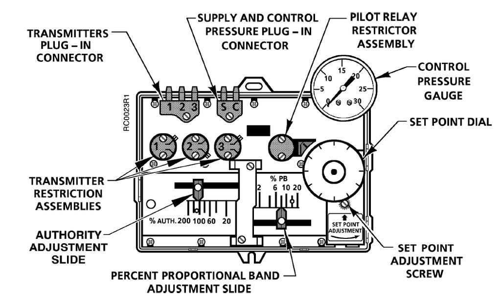
5 Terms Authority Adjustment The adjustment on a receiver controller which determines the effect of the reset signal from a secondary transmitter as a percentage of the primary signal from the primary transmitter.
6 Devices PE
7 Device EP
8 Device Thermostat
9 Device Reversing
10 Oil Free & Dry Control Air Pneumatic control system s worst enemy is air leaks. Air systems are normally specified for a 33% run-time and some specifications have allowed up to a 50% run-time on the air compressor. To put this very simply, an air compressor runs a desired 20 minutes or up to a maximum of 30 minutes out of every hour. Excessive run-time can be caused by the air compressors inability to produce the air supply it was selected for or more likely caused by system air leaks.
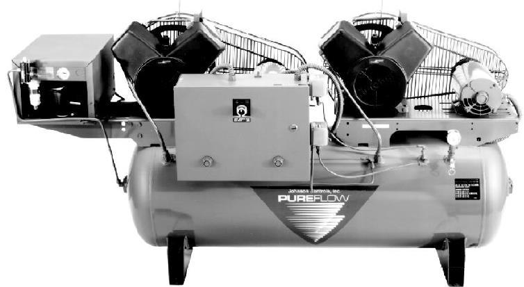
11 Air Compressors
12
13
14 Air Compressors Two types of air compressors are most commonly used on pneumatic control systems. These air oil lubricated and oil-less compressors. The excessive run-time affects each compressor differently.
15 Air Compressors The oil lubricated type compressor will overheat the cylinders and piston rings will wear, then oil will be allowed to pass past the rings into the air supply system. When the rings start to wear out the compressor will also need to run longer to produce the system air requirements and continues to compound the problem. These compressors are most commonly used because of the quieter operation.
16 Air Compressors The oil-less type compressor will overheat the cylinders and piston rings will wear out more quickly. Ring wear will not allow cylinders to compress or ring breakage causes broken piston rings to lodge against pistons and piston can become stuck. Stuck pistons break connecting rods or will make motor cycle on internal overloads. They do produce the best compressed air, but require the most maintenance and are much noisier than oil lubricated air compressors.
17 Air Compressors Pneumatic control air compressors use special internal oil control, which is designed to reduce oil carryover. Make sure you ask your supplier for this type of compressor
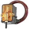
18 OIL FREE & DRY CONTROL AIR Refrigerated air dryers cool the air stream to a very low temperature, which will not support the high moisture of the compressed air. Moisture then condenses out of air stream and is then collected in a float/trap assembly. The water is drained out when trap level is exceeded. Oil filters are not always installed in a new system and are usually added if air compressor requires additional oil during operation.

19 System Pressures Operating range 3-15 PSIG Compressor output max.30 PSIG 2 stage regulator first 16 second 20 to 25 PSIG. Some old systems run at 15 PSIG


20 Air-System Relief Valve Air-Compressor Auto Drain Oil Filter PSIG PRV 30 PSIG Relief 0-30 PSIG Auto Drain
21 Refrigerated Air Dryer The refrigerated air dryer cools the incoming compressed air first in an air-to-air heat exchanger where the outgoing cool dry air pre-cools the hot incoming air and condenses some moisture out. Then the incoming air enters an air-to-refrigerant heat exchanger where the air is cooled to 38º F by the liquid refrigerant. This process causes the moisture to condense into liquid water and it is drained away. The out going air then enters the air-to-air heat exchanger and is warmed up to keep the outside of pipes from sweating. The refrigeration compressor pumps hot hi-pressure gas refrigerant (Freon) into the condenser which transfers the heat from the refrigerant gas to the ambient air as the gas condenses into a liquid. The liquid refrigerant (Freon) is then metered to a cold low pressure where it enters the air-to-refrigerant heat exchanger and the heat from the hot compressed air is adsorbed into the cold refrigerant (Freon). The refrigeration compressor then sucks low pressure hot gas refrigerant (Freon) into the refrigeration compressor and the cycle starts over again.
22 Thermostats
23 Single Pipe
24 Two Pipe
25 Pneumatic Thermostat Modulates compressed air to control pneumatic components when a change in space conditions is sensed. The thermostat bleeds or BILDS air pressure to affect system pressure in the pneumatic piping. Can be 1 or 2 pipe models.
26 Thermostats Pneumatic Use one pipe thermostat when tubing run is less than 50 ft Fewer than four controllers will be controlled from a single stat. Slower response is desired from stat.
27 Thermostats Pneumatic Use two pipe stat when Tubing runs more than 50 ft. Four or more controllers from a single stat. High capacity air is required dure to restrictions in the air line.
28 Thermostats Pneumatic In general both one and two pipe states have a gain of 2.5 psi per degree Fahrenheit.

29 Temperature Controller Application Room Thermostat B M psig M Control Valve
30 Temperature Controller Application B M psig M N/O 8-13 PSIG Heating Control Valve N/C 8-13 PSIG Cooling Control Valve
31 Single Pipe Thermostats B 20 psig Control Valve
32 3 Way Valve B M psig M Control Valve N/C C N/O Coil
33 Room Thermostat B M 16 psig Summer 25 psig Winter M Control Valve N/C C N/O Coil
34 Room Thermostat B M M P.E. Switch N n/o c n/c To Electric Device
35 Master/Submaster Controller A master controller is a pneumatic controller which transmits its output signal to another controller The second controller or submaster is similar to the standard type controller The significant difference is that the submaster set point will change as the signal from the master controller changes. This is normal used for reset

36 Master Submaster B M B M R M Space Thermostat Control Valve

37
38 3-WAY VALVE NORMALLY OPEN TO COIL

39 3-WAY VALVE NORMALLY CLOSED TO COIL
40 2-WAY VALVE NORMALLY 0PEN TO COIL

41 2-WAY VALVE NORMALLY CLOSED TO COIL
42 Receiver Controller

43 Receiver Controller Terms
44 Transmitters Pneumatic temperature transmitters are designed to measure air or fluid Temperature In pneumatic control systems The range is 3-15 PSIG
45 Span The difference between a temperature controllers or transmitter lowest possible set point and the highest possible set point. Example 40 to 240 deg
46 Terms Throttling range The change in the controlled condition necessary for the controller output to change over a 3-15 psig range. TR = in % TR/Span Example Deg Transmitter You would like a 20 Throttling range % = 20/100 or 20%
47 Terms Authority Adjustment Or Ratio The adjustment on a receiver controller which determines the effect of the reset signal from a secondary transmitter as a percentage of the primary signal from the primary transmitter.
48 Terms Sensitivity or Gain The psig change in transmitter output signal per engineering unit. Degree, %, RH, ETC. Sensitivity = 12 PSIG ( output Span) Transmitter Span
49 Temperature Transmitters sensitivity Example = 3-15 PSI = =.12 PSI/Degree Range degrees x.12 = 6.00 PSI + 3 PSI (Low Value) = 9 PSI or 50 Degree
50 ? What you are trying to control to
51 Integral The integral calculation responds to the length of time the measured variable is not at setpoint. The longer the measured variable is not at setpoint the larger the output of the integral calculation.
52 Proportional This calculation responds to how far the measured variable is from the setpoint. The proportional calculation has a much stronger effect on the result of the PID calculation than either the integral or derivative calculation.
53 Drivative This calculation responds to the change in error. In other words it responds to how quickly the measured variable is approaching setpoint This calculation can be used to smooth an actuator motion or cause an actuator to react faster
54
55
56
57
58
59 Single Input Receiver Controller Application B M S M Control Valve Temp. transmitter N/C C Return Supply N/O Discharge Air
60 Single Input Calibration Set for direct or reverse action using spring and pivot screws ETC. Calculate proportional Band. Proportional band = Throttling range Sensor Span X100
61 Duel Input Receiver Controller Application Receiver Controller OSA Temp. B M S S M Control Valve Temp. transmitter N/C C Return Supply N/O Discharge Air
62 Duel input Calibration Example See IOM For your Receiver controler
63 Duel input Calabration
64 Duel input Calabration
65 Duel input Calabration
66 Reset Schedule T1 Supply T2 OSA 200 Deg. 0 Deg. 150 Deg. 32 Deg. 100 Deg. 65 Deg.
67
68
69 Pneumatic Controls Require Calibration Every pneumatic control needs annual calibration at a minimum. Devices such as heat/cool thermostats need calibration twice a year. All pneumatic devices are calibrated in a similar manner, but will require other devices to be checked prior to it being calibrated. This will be explained further below.
70 Thermostats A pneumatic gauge is installed in the thermostat calibration port (this will very by manufacturer). Some will use a gauge connected to an end similar to a petes plug pressure needle, some will use ends similar to hypodermic needles, and others just un-screw a plug, then pushed a flexible hose over this plug. A temperature reading is taken at the thermostat and thermostat set-point dial is set to the temperature we read earlier. If the thermostat is calibrated, then the gauge pressure reading should equal 8 PSI. Every manufacturer does have a different way of calibration if it is above or below the 8PSI and you can get a copy of this procedure from the manufacturer.
71 Temperature Transmitters Transmitters are used to transmit a temperature value in pressure units. They will transmit these values to other pneumatic devices (i.e. Receiver Controllers, Switching Relays, Etc.). Every transmitter has a range or scale (i.e Degrees, degrees, etc.) that its pressure output is to correlate too. The transmitters will very its temperature over the scale or range vs. its 3-15 PSI output. Take a temperature reading at the transmitter-sensing element and for our example it was 50 degree. A pressure gauge with 1/10th of pound markings will help in getting accurate pressure readings or you can buy a receiver control calibration/simulation tool that already has these gauges.
72 Receiver Controllers This device is the most versatile of all pneumatic control devices. The transmitters sensing temperature, humidity, pressure or other values transmit a signal that is proportional to the medium being sensed. This signal is transmitted to a summing and amplifying point where it is converted to a control signal. This control signal leads to a controlled device and, in turn, corrects the controlled medium.
73 Receiver Controllers The control strategies that this device can perform are single input proportional, reset control, high & low limit control, differential temperature control, differential pressure control and many others.
74 Receiver Controllers The best method of checking calibration of this device is to use a receiver controller calibration/simulator. All inputs can be varied to test it against the correction made to the control signal output.
75 Controlled Devices

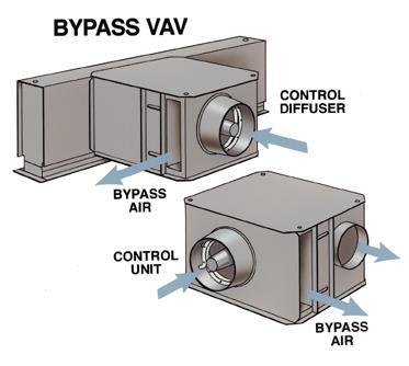
76 VAV Systems
77 VAV
78 Small control valves You can hook-up a squeeze bulb to the diaphragm, pump it up to 15 PSI and check to see if it holds pressure. If it does not hold pressure, then replace the valve diaphragm.
79 Small control valves Another replacement part on this type of valve is the seat disc. These can be replaced if valve allows a temperature rise or drop past the valve when shut. Verify that the system operating pressure has not exceeded the valves close-off capabilities before condemning valve seat. If disc replacement does not resolve temperature rise or drop, then the seat has a problem. Most of these valves are built to be cost effective and very few have the ability to replace the valve seat. The seat is usually machined into the bronze valve body and the only resolution in this type of valve is to replace it.
80 Small control valves The last part that is replaceable in this type of valve is the packing around the valve stem. Not all manufacturers make a valve with replaceable packing discs and if valve leaks around the stem, it will need to be replaced. If valve does have replaceable packing, then remove valve operator, take out packing with a packing pick and inspect valve stem. If valve stem shows a lot of corrosion, then do not bother trying to re-pack the valve stem, since it will more than likely leak again. Some older valves did not use packing and used a flexible bellows assembly attached to the stem. These bellows can be replaced, but you might want to evaluate this repair vs. the valve replacement.
81 Large Control Valves You can hook-up a squeeze bulb to the diaphragm, pump it up to 15 PSI and check to see if it holds pressure. If it does not hold pressure, then replace the valve diaphragm.
82 Large Control Valves Another replacement part on this type of valve is the seat disc. These can be replaced if valve allows a temperature rise or drop past the valve when shut. Verify that the system operating pressure has not exceeded the valves close-off capabilities before condemning valve seat. If disc replacement does not resolve temperature rise or drop, then the seat has a problem. Most of these valves are built of cast iron bodies and the seat is machined into this casting. The seat can be resurfaced with a seat grinder. If all of the above do not resolve the problem, then the only other resolution would be to replace the valve body.
83 Large Control Valves The last part that is replaceable in this type of valve is the packing around the valve stem. All manufacturers make a valve with replaceable packing discs and if valve leaks around the stem, it will need to be replaced. Remove the valve operator, take out packing with a packing pick and inspect valve stem. If valve stem shows a lot of corrosion, then do not bother trying to re-pack the valve stem, since it will more than likely leak again. If stem is ok, then re-packing is done installing packing with a stem lubricant and will tighten against stem when packing nut is re-tightened. Some valve manufacturers allow for the installation of stem lubricators and when you turn in stem nut, it pushed in more lubrication into the packing.
84 Damper Operators You can hook-up a squeeze bulb to the diaphragm, pump it up to 15 PSI and check to see if it holds pressure. If it does not hold pressure, then replace the valve diaphragm.
85 Damper Operators The operation is normally sequenced with other devices. This depends on the spring ranges of each to properly open/close at the right pressure. If springs weaken, they will not sequence properly and you can install a pilot positioner, which will be set to open or close at proper pressure. Some system specifications require these on all sequenced devices and will not allow sequencing to be done only by the spring ranges.
86 Dampers These devices do not need much preventative maintenance, but external linkages can loosen, which will not allow dampers to fully shut. Damper should be stroked fully open and closed to verify that it they work properly. Large dampers are linked with jack shafting and these can also not open/close all damper sections uniformly. Adjustments may be necessary to verify that this operation occurs.
87 Dampers Some damper manufacturers suggest that a Teflon lubricant be sprayed on moving parts to maintain smooth operation.
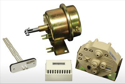
88 Pneumatic Controls Components Pneumatic Volume Regulator Reversing Relay Signal Limiter Booster Relay
89
90
91
92
93
94
95
96
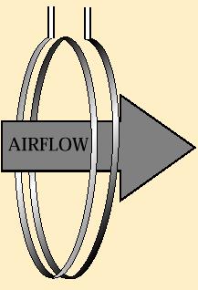
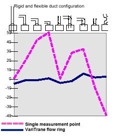
97 Air Valve Bevelled, self-centering damper w/al cast inlet - even airflow/quiet operation - low leak, less than 1% 4 Integral electric/pneumatic actuator - nothing to get out of adjustment - not exposed to jobsite abuse Patented multi-point/axis sensing flow ring - linear airflow characteristics - stable control for all inlet configuration

98


99 Air Valve airflow damper actuator


100 VAV Terminal Units supply air primary air airflow modulation device terminal heating coil filter terminal mixing fan

101 Air Valve Bevelled, self-centering damper w/al cast inlet - even airflow/quiet operation - low leak, less than 1% 4 Integral electric/pneumatic actuator - nothing to get out of adjustment - not exposed to jobsite abuse Patented multi-point/axis sensing flow ring - linear airflow characteristics - stable control for all inlet configuration
102
103
104
105
106
107


108 VAV terminal unit controls Primary Airflow Measurement airflow measured pressure difference airflow sensor
109
110
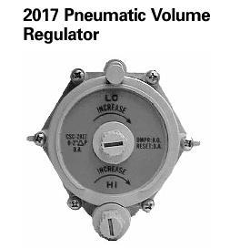
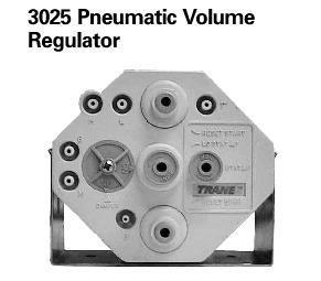
111
112


113
114
115

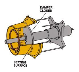
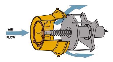
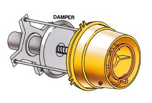
116 VAV terminal unit controls Pneumatic primary air return spring damper bladder pneumatic pressure
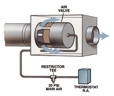
117 Air Valves Normally Open Air Valve 3-8 psi Normally closed air Valve 8-13 psi
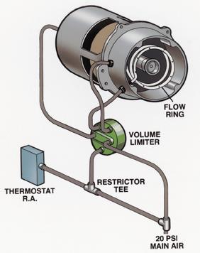
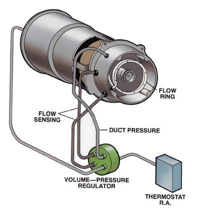
118 Pneumatic Volume Regulator Provides consistent airflow to the space regardless of varying inlet duct pressure conditions in response to a thermostat signal Minimum and Maximum airflow set points are also maintained by the controller.
119
120
121
122


123 Pneumatic Controls Pressure Dependent - actuator only - position limiters - constant loads, interior zones Pressure Independent - airflow regulators (PVR) control regardless of inlet sp changes - adjustable cfm settings std, min and max - typical of exterior zones
124

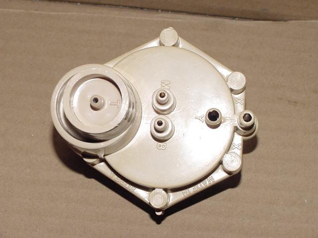
125 Y=Low X=High
126
127
128
129
130
131
132
133
134
135
136
137
138
139 VAV terminal unit controls Pneumatic Pneumatic Volume Regulator (PVR) provides pressure-independent control Pneumatic thermostat directly controls terminal unit fan and heat source Minimum and maximum airflow settings adjusted physically on PVR Compressed air operates modulation device, PVR and space thermostat

140 Reversing Relay A pneumatic reversing relay is a proportional non bleeding device that reverses an input signal based upon a pre-set constant.

141 Reversing Relay The reversing relay requires three piping connections. Main/Supply and Output air The branch line pressure decreases in direct proportion to an increase in input signal pressure and vice-versa.
142
143

144 Signal Limiter The signal limiter is a pneumatic device that limits the pneumatic pressure signal to the air valve.air flow delivery from the air valve is limited by the valve position and duct work static pressure Typically used on a system without a pneumatic volume regulator.air flow through the air valve is pressure dependent.
145 Signal Limiter Used as either a minimum or maximum limiter. The Minimum/Max limiter can be installed with either a one or two pipe thermostat
146

147 Signal Limiter (Min-Max) Limits Travel of actuator Used in place of Volume Regulator
148

149 Booster Relay The booster relay device amplifies or boosts a given pneumatic signal. This device may be useful during unit calibration or system air balancing. Standard on most large air valves.

150 Electric-Pneumatic relay Relay to switch with an electric voltage the supply air pressure to one or the other output ports
151 Room Thermostat B M M P.E. Switch N n/o c n/c To Electric Device
152

153 Pneumatic Selector Relay Thee-port relay to transmit the higher of two input signals
154 Hi Selector Relay M 5 # # 2 Relay 5 # 3 10 # 10 # 5 2 Relay
 Pressure change. It can also divert a supply line to one of two branches.")
155 Pneumatic Snap Action Relay The four port, snap action relay converts a proportional air pressure change from a controller to a positive (two-position) Pressure change. It can also divert a supply line to one of two branches.

156 Snap-Action relay M Pilot Normally Closed Normally Open Common M Snap-Action relay

157 Pneumatic Switching relay Pneumatic switching relays block, divert, or bleed pneumatic air lines when pilot pressure is changed from one specific value to another. Commonly applied in Day-Night, Summer-Winter, Start-Stop, On-Off-Auto and other Changed as conditions change.
158
159 Pneumatic Capacity relay A direct acting, proportional relay suitable for use in HVAC systems to increase the capacity of a branch line signal to a pneumatic valve or damper operator. 1:1 pressure ratio Can be used to transmit the lower of 2 pressures
160 Capacity relay Restrictor M Additional Actuators Pilot M EXH.

161 Pneumatic Ratio Relay Produces a modulating pressure output proportional to pilot pressure changes This four-port non-bleed direct-acting relay is used to control valves or dampers in sequence from a single pressure input
162 Ratio relay M 3-8 PSIG Pilot Ratio Relay M EXH PSIG Ratio Relay M EXH.
163 Pneumatic Potentiometer Three port pneumatic potentiometer can sum two input pressures average two input pressures, be an adjustable flow restriction, or be an adjustable pressure supply.
164
Pneumatic Controls. Pneumatic Controls Sections
 Pneumatic Controls Pneumatic Controls Sections Controllers and Switches Thermostats Relays Sensors and Transmitters See the Contents Section at the front of the Product Catalog for the complete data sheet
SECTION AIR TERMINAL UNITS
 SECTION 23 36 00 AIR TERMINAL UNITS PART 1 - GENERAL 1.1 SUMMARY A. Section includes constant volume terminal units, variable volume terminal units, dual duct terminal units, fan powered terminal units,
POWERS TM CONTROLS LC Pneumatic Damper Actuator
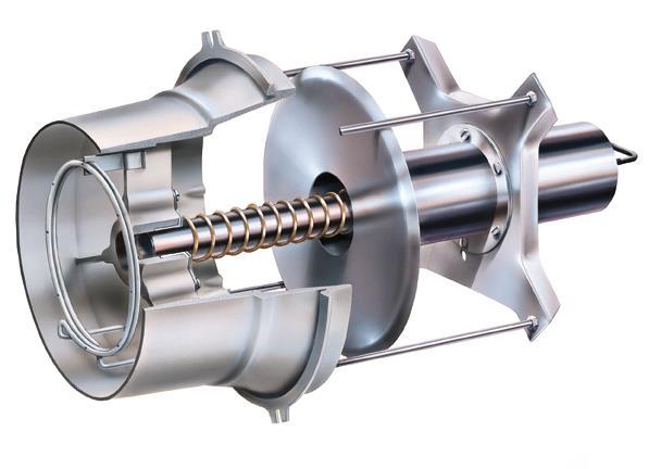
 POWERS TM CONTROLS Document No. 155-030P25 AP 331-4 Description Features The LC Actuator is a piston type pneumatic actuator. Air pressure is supplied to both sides of the piston to provide a force balance
POWERS CONTROL RC 195 Multiple Input Receiver- Controller
 POWERS CONTROL RC 195 Multiple Input Receiver- Controller Document No. 155-036P25 RC 195-1 Description Features Application The RC 195 Multiple lnput Receiver-Controller is a pneumatic instrument which
Distributed By: M&M Control Service, Inc PRODUCT PRODUCT CODE TECHNICAL INSTRUCTIONS PAGE #
 PRODUCT PRODUCT CODE TECHNICAL INSTRUCTIONS PAGE # Switches Selector Switches SW 786 155-118P25 G-3 Positioning Switch SW 141 155-117P25 G-5 Enthalpy Control Switch EE 141 155-054P25 G-7 Static Pressure
TK-6024, TK-6124, TK-8024, TK-8124
 TK-6024, TK-6124, TK-8024, TK-8124 Pneumatic Bulb Thermostats General Instructions APPLICATION For proportional temperature control of pneumatic valves and actuators to maintain air or liquid temperatures
N-1001 Economizer Logic Network
 24-7074- 6, Rev. A N-1001 Economizer Logic Network Product Bulletin N-1001 Issue Date 0316 Features Choice of O.A. Dry Bulb Economizer, Differential Temperature Economizer, or Enthalpy Economizer cycles
VAV Terminal Unit Control Package
 VAV Terminal Unit Control Package Model CP-133-STK Pneumatic Pressure Independent, VAV Cooling, Constant Volume Heating at Min CFM set point. This actuator/controller will accommodate Direct or Reverse
BAS Construction Checklist
 BAS Construction Checklist Project: Building: Location: Submittal / Approvals Submittal. The above equipment and systems integral to them are complete and ready for functional testing. The checklist items
SECTION HVAC CONTROL SYSTEM PART 1 GENERAL 1.01 SUMMARY. A. Section Includes:
 SECTION 15970 HVAC CONTROL SYSTEM PART 1 GENERAL 1.01 SUMMARY A. Section Includes: 1. Thermostats, temperature transmitters, controllers, automatic valves, dampers, damper operators, pneumatic/ electric
* T Temperature-Indicating Dial (Must be field set and calibrated to an actual thermometer)
") 175/153 Series Watson McDaniel reserves the right to change the designs and/or materials of its products without notice. 2006 Watson McDaniel Company 175 HEATING 153 COOLING 175 / 153 Screwed Connection
175/153 Series Watson McDaniel reserves the right to change the designs and/or materials of its products without notice. 2006 Watson McDaniel Company 175 HEATING 153 COOLING 175 / 153 Screwed Connection
W91/W94 Series TEMPERATURE REGULATORS. Self-Operated Temperature Regulators. Design & Operation W91 Non-Indicating W94 Dial Thermometer
 Design & Operation W91 Non-Indicating W94 Dial Thermometer Watson McDaniel reserves the right to change the designs and/or materials of its products without notice. 2010 Watson McDaniel Company CAPILLARY
Fisher 2506 and 2516 Receiver Controllers
 2506/2516 Receiver Controllers Product Bulletin Fisher 2506 and 2516 Receiver Controllers The 2506 receiver controller takes the input from a pneumatic transmitter, matches it against the adjustable set
Air Handling Unit Construction Checklist
 Air Handling Unit Construction Checklist Project: Date: AHU Tag: Location: Submittal / Approvals Submittal. The above equipment and systems integral to them are complete and ready for functional testing.
AK Application. Features. Applicable Literature. Positive Positioner Pneumatic Relay General Instructions
 TAC 1354 Clifford Avenue P. O. Box 2940 Loves Park, IL 61132-2940 www.tac.com Positive Positioner Pneumatic Relay General Instructions Application The Positive Positioner Pneumatic Relay is used to accurately
SEASONAL MAINTENANCE CHECKLISTS Johnson Controls
 SPRING CHECK LIST ABSORPTION CHILLERS Check starter and control panel. Leak test. Check hand valve diaphragms and replace as required. Check operation of purge unit. Change oil in the purge pump. Lubricate
Distributed By: M&M Control Service, Inc
 Control Valves DESIGN & OPERATION Description A control valve is a device capable of modulating flow at varying degrees between minimal flow and full capacity in response to a signal from an external control
Distributed By: M&M Control Service, Inc PRODUCT PRODUCT CODE RESOURCE DOCUMENTS PAGE #
 PRODUCT PRODUCT CODE RESOURCE DOCUMENTS PAGE # Pneumatic Receiver-Controllers Single Input Receiver-Controller RC 195 155-119P25 C-3 Multiple Input Receiver-Controller RC 195 155-036P25 C-5 Pneumatic Transmitters
100% OUTSIDE AIR MAKE-UP UNITS WITH DISCHARGE TEMPERATURE CONTROL & c.pco DIRECT DIGITAL CONTROL MODULE
 100% OUTSIDE AIR MAKE-UP UNITS WITH DISCHARGE TEMPERATURE CONTROL & c.pco DIRECT DIGITAL CONTROL MODULE Start-up must be performed by a trained, experienced service person. The following general start-up
Section Va: Valve Actuators
 Valve and Actuator Manual 977 Actuator Basics and Sizing Information Section Engineering Data Book Va Issue Date 0592 Section Va: Valve Actuators Pneumatic Actuators Page 3 Electric Actuators 5 Maximum
PNEUMATIC CONTROL SYSTEMS DESIGN AND CONSTRUCTION STANDARD PART 1 - GENERAL. A. Codes and Standards that are Standard at the University:
 PART 1 - GENERAL 1.01 Purpose: A. This design guideline contained here in includes the requirements for pneumatic control systems at The University of Texas at Austin. It is the intent to provide the highest
VAV TERMINAL UNITS. VVD VAV Diffusers
 Introduction ASLI VAV diffusers, VVD are variable air volume diffuser for supply air in variable air volume system. In many conventional HVAC systems, multiple work spaces are controlled by a single thermostat.
Variable Air Volume (VAV) Pressure Independent Control
 Pressure Independent Control") VAV Terminal Units Asli Variable Air Volume (Vav) Terminal Units are volume flow rate controller for supply air on variable air volume system. These units are designed to control the airflow rate of conditioned
VAV Terminal Units Asli Variable Air Volume (Vav) Terminal Units are volume flow rate controller for supply air on variable air volume system. These units are designed to control the airflow rate of conditioned
Powers Controls TT 184 Temperature Transmitters
 Powers Controls Document No. 155-077P25 TT 184-1 Room Transmitter Remote Bulb Average Bulb Rigid Bulb Description The are direct acting, one-pipe instruments that sense temperature and transmit a proportional
Moniteur INSTALLATION & OPERATING INSTRUCTIONS. SERIES 40 Positioners. Installation and Operating Instructions Series 40 Positioners.
 INSTALLATION & OPERATING INSTRUCTIONS SERIES 40 Positioners Form IO2-0406 Description of Device Moniteur's Series 40 pneumatic (3-15psi) and electropneumatic (4-20mA) positioners are advanced control devices
ZIP Economizer Fault Detection and Diagnostics (FDD) Table
 Table") Fault Detection and Diagnostics (FDD) Table Fault Detection Problem Diagnostic ction (in addition to alarm stored / transmitted) Potential Cause C Fault Code OT sensor predetermined range O damper returns
Fault Detection and Diagnostics (FDD) Table Fault Detection Problem Diagnostic ction (in addition to alarm stored / transmitted) Potential Cause C Fault Code OT sensor predetermined range O damper returns
SDL Single-Duct, Low-Height, VAV Terminals
 SDL -Duct, Low-Height, VAV Terminals SDL -Duct, VAV Terminals: Fit more comfort in less space Owners SDL terminals offer the typical benefits provided by single-duct units, while performing at extremely
Jordan Control Valve Series
 Jordan Control Valve Series Control Valves A control valve is used to manipulate flowing fluids like, gas, water, steam or process solutions. It compensates for changes in flow or pressure and regulates
Flare Valves 1/2 inch 2-Way and 3-Way
 Valve and Actuator Manual 977 Valve Product Information Section Product Bulletin VTF Series Issue Date 0596 Flare Valves 1/2 inch 2-Way and 3-Way The 1/2 inch flared valve line is designed to accurately
SECTION PIPING SPECIALTIES PART 1 GENERAL 1.1 SUMMARY
 SECTION 230533 - PIPING SPECIALTIES PART 1 GENERAL 1.1 SUMMARY A. Section Includes: 1. Pressure gages. 2. Pressure gage taps. 3. Thermometers. 4. Thermometer supports. 5. Test plugs. 6. Static pressure
User s Manual. Pneumatic Positioner. Series 58. J Flow. Series 58. J Flow
 Pneumatic Positioner Series 58 User s Manual J Flow Series 58 J Flow Series 58 J Flow Controls, LLC 14 De Camp Cincinnati, OH 45216 Phone: 513-731-2900 Fax 513-731-6939 www.jflowcontrols.com Introduction
DESCRIPTION AND OPERATION
 Page 1 of 10 DESCRIPTION AND OPERATION AIR DELIVERY DESCRIPTION AND OPERATION The air delivery description and operation is divided into five areas: HVAC Control Components Air Speed Air Delivery Recirculation
Understanding the benefits of using a digital valve controller. Mark Buzzell Business Manager, Metso Flow Control
 Understanding the benefits of using a digital valve controller Mark Buzzell Business Manager, Metso Flow Control Evolution of Valve Positioners Digital (Next Generation) Digital (First Generation) Analog
SECTION Pressure & Temperature Control
 16 Pressure & Temperature Control ARMSTRONG PRODUCT CATALOGUE 70 Pressure Reducing s Pressure Reducing s Armstrong pressure reducing valves (PRVs) and temperature regulators help you manage steam, air
470 Series Piston Actuators
 January 000 Bulletin 61.:470 470 Series Piston Actuators The 470 Series pneumatic piston actuators (figure 1) are used in either throttling or on-off applications with control valves having 90.5 mm (3-9/16
General Information... 2
 VAV Flow Controller-Actuators CSP 5001/5002 Applications Guide General Information... 2 CSP 5001/5002 Overview...2 Controller, Sensor, and Thermostat Functions...3 Wiring...4 Air Flow Sensor Connection...4
CENTAC Inlet and Bypass Valve Positioners
 CENTAC Inlet and Bypass Valve Positioners INGERSOLL-RAND AIR COMPRESSORS INLET AND BYPASS VALVE POSITIONERS Copyright Notice Copyright 1992, 1999 Ingersoll-Rand Company THIS CONTENTS OF THIS MANUAL ARE
STAR DAMPERS ASTRAL ACTUATOR (DA SERIES)
") STAR DAMPERS ASTRAL ACTUATOR (DA SERIES) An On/Off Motorized Damper Actuator. Star dampers are designed primarily for use on cool or warm air ducted systems. Star actuators are compatible and interchangeable
STAR DAMPERS ASTRAL ACTUATOR (DA SERIES) An On/Off Motorized Damper Actuator. Star dampers are designed primarily for use on cool or warm air ducted systems. Star actuators are compatible and interchangeable
Adjustable Differential Relay A1
 Sales Manual Section 332 PRODUCT SPECIFICATION MODEL 84871-A1 GENERAL DESCRIPTION The 84871-A1 Adjustable Differential Diverting Relay is a two-position, snap-acting, three-way relay. Its normal function
Self-Operating Temperature Regulators
 Self-Operating Temperature Regulators Remote Bulb for Heating, Cooling, Mixing and By-Pass Applications Powers # Regulators With Powers # Self-Operating Temperature Regulators, you no longer need external
Powers Controls RL 147 Positioning Relay
 Powers Controls Technical Instructions Document No. 155-038P25 RL 147-2 Description Features Rapid response Product Numbers See Table 1. The is a compact, pneumatic device designed to provide positive
VG7000 Series Bronze Control Valves
 VG7000 Series Bronze Control Valves Product Bulletin VG7000 Series Code No. LIT-977140 Issued June 16, 2008 Supersedes March 2001 VG7000 Series Bronze Control Valves are designed primarily to regulate
TSS Single-Duct VAV Terminals
 TSS Single-Duct VAV Terminals Model TSS construction features Standard Construction Mechanical-lock construction ensures lowest possible casing leakage Roll-formed inlet collar with integral stiffening
Powers Controls Powertop Two-Way Valves Normally Open
 Powers Controls Powertop Two-Way s Normally Open VP 658-5 Description The VP 658 normally open valves are pneumatically operated valves designed to control the flow of both water and steam. Features Stainless
VG7000 Series Bronze Control Valves
 FANs 977, 125, 1628.3 Product/Technical Bulletin VG7000 Issue Date 0301 VG7000 Series Bronze Control Valves VG7000 Series Bronze Control Valves are designed primarily to regulate the flow of water and
TEMPERATURE REGULATORS W91/W94 Series
 Self-Operated Temperature Regulators Watson McDaniel reserves the right to change the designs and/or materials of its products without notice. 2010 Watson McDaniel Company Self-Operating Design Indicating
SECTION METERS AND GAGES FOR PLUMBING PIPING
 PART 1 GENERAL 1.01 SECTION INCLUDES A. Positive displacement meters. B. Flow meters. SECTION 22 0519 METERS AND GAGES FOR C. Pressure gages and pressure gage taps. D. Thermometers and thermometer wells.
Control Valves Positioner
 Control Valves Positioner HiFlo Valve Positioner Easy calibration Corrosion-resistant cover and base Withstands 150 psi at all parts Two -sided cam for easy field reversibility Optional / NPT for piped
Control Valves Positioner
 Control Valves Positioner HiFlo HiFlo Valve Positioner Corrosion-resistant cover and base Easy calibration Withstands 150 psi at all parts Two -sided cam for easy field reversibility Optional / NPT for
Fisher 480 Series Yokeless Piston Actuators
 480 Series Actuators Product Bulletin Fisher 480 Series Yokeless Piston Actuators Fisher 480 Series actuators are yokeless piston actuators that are used in either throttling or on-off applications with
RETROFIT TERMINAL UNITS
 GENERAL PROUCT OVERVIEW Retrofit Terminal s Convert Constant Air Volume Systems to Variable Air Volume. Convert Constant Volume ual uct Systems to Variable Air Volume. Convert Multizone Systems to Variable
Cla-Val. Service Training Manual. Simple solutions plus learning with a purpose
 Cla-Val Service Training Manual Simple solutions plus learning with a purpose 5 Application Series Section General Identify What Valve You Have 5-1 Rate of Flow 40 Series 5-2 Pressure Relief 50 Series
ITT Conoflow Process Control Solutions
 ITT Conoflow Process Control Solutions Process Control Solutions About ITT Conoflow Under the ITT Conoflow brand, ITT is a market-leading manufacturer of Instruments and Controls for the various segments
Product Data. 35J Single-Duct Retrofit Terminal Units for Variable Air Volume Systems. 40 to 3700 cfm
 Product Data 35J Single-Duct Retrofit Terminal Units for Variable Air Volume Systems 40 to 3700 cfm The 35J retrofit terminal units offer: Unit casing of 22-gage galvanized steel construction (optional
START-UP CHECKLIST. Date: Job Name: Customer Name: Address: City: State: Zip: Model Number: Serial Number: Qualified Start-up Technician:
 START-UP INSTRUCTION START-UP CHECKLIST SERIES 5 36000 To 72000 BTU S PACKAGE UNITS 3 To 6 Ton Date: _ Job Name: Customer Name: Address: City: State: Zip: Model Number: Serial Number: Qualified Start-up
MS Application. Features. Proportional Valve Actuator General Instructions
 Proportional Valve Actuator Application The Proportional Valve Actuator is a non-spring return actuator used with proportional to 10 Vdc or 4 to 0 ma controllers and standard 1/" to 1-1/4" two-way and
Dual Duct Variable Air Volume Terminal (Model TDS)
") Product Bulletin Issue Date June 21st, 2005 Dual Duct Variable Air Volume Terminal (Model TDS) Model TDS terminals provide Variable Air Volume (VAV) control beyond the typical dual duct box. They are specifically
Product Bulletin Issue Date June 21st, 2005 Dual Duct Variable Air Volume Terminal (Model TDS) Model TDS terminals provide Variable Air Volume (VAV) control beyond the typical dual duct box. They are specifically
Engineering Bulletin. IntelliPak RTM (Rooftop Module, 1U48) Subject: Generic Building Automation System (GBAS, UCM Module, 1U51)
 Subject: Generic Building Automation System (GBAS, UCM Module, 1U51)") Engineering Bulletin IntelliPak RTM (Rooftop Module, 1U48) Subject: Generic Building Automation System (GBAS, UCM Module, 1U51) Issued By: Clarksville Marketing and Sales Support Order No. UN-PRB001-EN
Engineering Bulletin IntelliPak RTM (Rooftop Module, 1U48) Subject: Generic Building Automation System (GBAS, UCM Module, 1U51) Issued By: Clarksville Marketing and Sales Support Order No. UN-PRB001-EN
Test Which component has the highest Energy Density? A. Accumulator. B. Battery. C. Capacitor. D. Spring.
 Test 1 1. Which statement is True? A. Pneumatic systems are more suitable than hydraulic systems to drive powerful machines. B. Mechanical systems transfer energy for longer distances than hydraulic systems.
Installation Manual. Mixing Box Control Systems Installation, Operation, and Maintenance Manual. 605 Shiloh Road Plano, Texas
 Installation Manual IOM-MBC-00 08-30-04 Mixing Box Control Systems Installation,, and Maintenance Manual Contents Page Introduction...1 General...1 Safety...1 Inspection...1 Mixing Box Control Systems...2
VA, VF, and VS Series Direct Mounted Globe Valve Assemblies. Application. Features
 TAC 1354 Clifford Avenue P.O. Box 2940 Loves Park, Illinois 61132-2940 www.invensysibs.com Two-Way and Three-Way Globe Valve Assemblies with 220 lbf Linear (979 N) Spring Return DuraDrive Actuators Submittal
Blank-off. HVAC unit screws. Spacer for 1" filter ILL. 3. Screw
 ICP INSTALLATION INSTRUCTIONS for NPECOMZR00A00 ICP's economizer is convertible-it will work in either a down discharge or horizontal discharge application. Read these instructions completely and carefully
Python Series Control Valves
 s When accurate control is desired from your steam or water applications the Armstrong Python 1100 Series Control Valve will squeeze every bit of performance out of your system and deliver precise control.
Airbus A-320 SOLENOID THERMOSTAT (T.L.T).
.") Airbus A-320 SOLENOID THERMOSTAT (T.L.T). By Soumyadeep Das Raj shekhar Chatterjee Solenoid Thermostat of the Engine Air Bleed System Part Number: 341E010000 341E030000 341E030000 (AMD A) Component Maintenance
Airbus A-320 SOLENOID THERMOSTAT (T.L.T). By Soumyadeep Das Raj shekhar Chatterjee Solenoid Thermostat of the Engine Air Bleed System Part Number: 341E010000 341E030000 341E030000 (AMD A) Component Maintenance
START-UP CHECKLIST. Date: Job Name: Customer Name: Address: City: State: Zip: Model Number: Serial Number: Qualified Start-up Technician:
 START-UP INSTRUCTION OPTIMUM 36000 To 72000 BTU S PACKAGE UNITS 3 To 6 Ton START-UP CHECKLIST Date: Job Name: Customer Name: Address: City: State: Zip: Model Number: Serial Number: Qualified Start-up Technician:
Powers TM Controls SW 141 Differential Static Airflow Switches
 Powers TM Controls SW 141 Differential Static Airflow Switches Document No. 155-052P25 SW 1 0518 Description The SW 141 Airflow Switch senses static differential pressure and the diaphragm operated snap
Remote Temperature Controllers. Quick Selection Guide
 Remote Temperature Controllers Quick Selection Guide A Complete Selection For A Wide Range Of Applications Electronic Standalone Controllers T775 Provide on/off, modulating, or reset control in applications
Pressure Sensor No Series
 Sales Manual Section 335 PRODUCT SPECIFICATION 84372 SERIES Pressure Sensor No. 84372-Series GENERAL DESCRIPTION The patented* No. 84372-Series Pressure Sensor contains a weatherproof, snap-acting valve
Fan Powered Low Profile Variable Volume Terminal Units
 MANUAL INSTALLATION Fan Powered Low Profile Variable Volume Terminal Units FEVLP / FPVLP / FDVLP Series v001 Issue Date: 07/19/16 07/19/16 Price Industries Limited. All rights reserved. TABLE OF CONTENTS
Product Data. Features/Benefits. 35K Bypass Terminal. 110 to 4400 cfm
 Product Data 35K Bypass Terminal 110 to 4400 cfm Carrier s 35K Series bypass terminals offer: 20-gage, galvanized steel casing construction 1/2-in. thick, dual density fiberglass insulation meeting NFPA
Features Globe Valve 2-Way & 3-Way Assembly Features:
 Rev: 10/22/13 Features Globe Valve 2-Way & 3-Way Assembly Features: DG Series Automated Applications for Building Automation, Temperature Controls, HVAC Two-Way and Three-Way Assemblies Chilled Water Hot
Air Conditioning Clinic. HVAC System Control One of the Systems Series TRG-TRC017-EN
 Air Conditioning Clinic HVAC System Control One of the Systems Series TRG-TRC017-EN NO POSTAGE NECESSARY IF MAILED IN THE UNITED STATES BUSINESS REPLY MAIL FIRST-CLASS MAIL PERMIT NO 11 LA CROSSE, WI POSTAGE
PRESSURE REDUCING CONTROL VALVE
 PRESSURE REDUCING CONTROL VALVE 06/08 Schematics Throttles to reduce high upstream pressure to constant lower downstream pressure Reducing setpoint is adjustable 2 (AOS) X P/L Standard Components 1 Main
POWERS Controls. Technical Instructions Document No P25 AP December 3, No. 6 Pneumatic Damper Actuator.
 POWERS Controls No. 6 Pneumatic Damper Actuator Technical Instructions AP 331-3 331-2793 Actuator 331-2857 Actuator with Clevis and Pin 331-3012 Extended Shaft and Frame Mounting Description The POWERS
SINGLE DUCT TERMINAL UNITS
 www.igcaire.com SINGLE DUCT TERMINAL UNITS Direct Digital Control, Pressure Independent FEATURES 22 Gauge Galvanized Steel Casing Construction with a 20 Gauge Casing Option that Provides Strength and Product
Temperature Regulators
 Temperature Regulators DESIGN & OPERATION DIAL THERMOMETER (Model 91400 only) BELLOWS OVERRANGE PROTECTION SPRING CAPILLARY TUBING CONNECTION SENSING BULB RANGE ADJUSTMENT SPRING CAP ADJUSTMENT SCREW BUSHING
Temperature Controller. TC5+2V4SA Plus USER'S MANUAL
 Temperature Controller TC5+2V4SA Plus USER'S MANUAL NOTICE Every effort has been made to ensure that this manual is complete, accurate and up-to-date. The information contained in it is however subject
Secondary Coolant 301
 Secondary Coolant 301 Instructor Rusty Walker Hill PHOENIX Learning Center Secondary Coolant 301 Start-Up Procedures Secondary Coolant 301 Objectives Describe the initial startup procedures for a medium
Screw. (Note 4) Spacer for 1" filter ILL. 3. Screw
 Spacer for 1 filter ILL. 3. Screw") ICP INSTALLATION INSTRUCTIONS for (NPECOMZR006A00) ICP's economizer is convertible-it will work in either a down discharge or horizontal discharge application. Read these instructions completely and carefully
ICP INSTALLATION INSTRUCTIONS for (NPECOMZR006A00) ICP's economizer is convertible-it will work in either a down discharge or horizontal discharge application. Read these instructions completely and carefully
RELEASING PRESSURE IN THE HYDRAULIC SYSTEM,
 Testing And Adjusting Introduction NOTE: For Specifications with illustrations, make reference to SPECIFICATIONS for 225 EXCAVATOR HYDRAULIC SYSTEM, Form No. SENR7734. If the Specifications are not the
Screw. (Note 4) Spacer for 1" filter ILL. 3. Screw
 Spacer for 1 filter ILL. 3. Screw") MicroMetl INSTALLATION INSTRUCTIONS for 0637-0311 (CPECOMZR006A00) MicroMetl's 0637 economizer is convertible-it will work in either a down discharge or horizontal discharge application. Read these instructions
MicroMetl INSTALLATION INSTRUCTIONS for 0637-0311 (CPECOMZR006A00) MicroMetl's 0637 economizer is convertible-it will work in either a down discharge or horizontal discharge application. Read these instructions
Mark 70 Series. Sliding Gate Control Valves. Pneumatic Control Valves Mark 70 Sliding Gate Control Valves MARK 70 FEATURES
 Mark 7 Series Sliding Gate Control Valves The MK7 Series is a line of pneumatically-operated diaphragm control valves that combine multiple spring actuators with the precision of Jordan Valve s advanced
VE411 & 431 SERIES ELECTRONIC SYSTEM CONTROL VALVES Universal two way, or three way mixing globe valves - 25mm to 100mm (1 to 4 )
") Universal two way, or three way mixing globe valves - 25mm to 100mm (1 to 4 ) ON VALVE BODIES VALVE ASSEMBLIES - These assemblies are complete with actuators, linkage assembly and valve body. They are
Universal two way, or three way mixing globe valves - 25mm to 100mm (1 to 4 ) ON VALVE BODIES VALVE ASSEMBLIES - These assemblies are complete with actuators, linkage assembly and valve body. They are
Introduction to Johnson Controls Dampers
 Damper and Actuator Product Guide 268.1 Damper Engineering Section Product Bulletin Issue Date 1297 Introduction to Johnson Controls Dampers For over 100 years, Johnson Controls has been the industry leader
IAQ. ROUND DUCT RETROFIT Model ARR
 Non Fan Powered Units ROUND DUCT RETROFIT Model ARR IAQ External Insulation Standard The Carnes Model ARR offers low pressure drop, low sound levels, and valve characteristics which create stable control
VE411 & 431 SERIES ELECTRONIC SYSTEM CONTROL VALVES Universal two way, or three way mixing globe valves - 25mm to 100mm (1 to 4 )
") Universal two way, or three way mixing globe valves - 25mm to 100mm (1 to 4 ) VALVE ASSEMBLIES - These assemblies are complete with actuators, linkage assembly and valve body. They are suitable for use
Universal two way, or three way mixing globe valves - 25mm to 100mm (1 to 4 ) VALVE ASSEMBLIES - These assemblies are complete with actuators, linkage assembly and valve body. They are suitable for use
VIFB Coil Technical Guide
 TGVIFB-5 VIFB Coil Technical Guide VERTICAL TUBE INTEGRAL FACE AND BY-PASS HEATING COILS FOR AIR PREHEATING Since 1875, the L.J. Wing Company has been a leader in providing innovative solutions for difficult
VAV TERMINAL UNIT KYODO-ALLIED TECHNOLOGY PTE LTD
 VAV TERMINAL UNIT KYODO-ALLIED TECHNOLOGY PTE LTD R CONTENTS MODEL: KYODO / KYODO-R... 1 INTRODUCTION... 1 APPLICATION... 1 VARIABLE AIR VOLUME SYSTEM... 1 FEATURES... 2 MATERIALS... 3 AIR VOLUME CONTROL
Modulating Furnace Information. Warning on Meter Setting - Read First!
 Modulating Furnace Information Pressure Transducer Pressure DC Volts 0.00" 0.25 0.20" 0.63 0.25" 0.72 0.30" 0.82 0.35" 0.91 0.40" 1.00 0.45" 1.09 0.50" 1.19 0.55" 1.28 0.60" 1.38 0.65" 1.47 0.70" 1.56
ECONOMIZERS. 5/2012 Supersedes
 Litho U.S.A. 2012 ECONOMIZERS 507031 01 5/2012 Supersedes 506747 01 K1ECON ECONOMIZERS INSTALLATION INSTRUCTIONS FOR ECONOMIZERS AND OUTDOOR AIR HOODS USED WITH KG/KC/KH 024, 030, 036, 048, 060, 072, 090
599 Series Zone Valve Bodies:
 599 Series Zone Bodies: Two-Way and Three-Way VE VV-1 Description Features The 599 Series two-way and three-way Zone s with a 1/10-inch (2.5 mm) stroke. Direct-coupled, universal bonnet Application Ordering
Direct or Reverse-Acting?
 Control Valves Use of Positioners Minimize the effects of friction & hysteresis / reduce dead band. Increase differential pressure capability. Permit split range operation / high rangeability in slow response
Fisher 480 Series Yokeless Piston Actuators
 Instruction Manual 480 Series Actuators Fisher 480 Series Yokeless Piston Actuators Contents Introduction... 1 Scope of Manual... 1 Description... 1 Specifications... 1 Educational Services... 4 Actuator
Variable Air Volume Dampers
 OVAV 2000 SERIES OPTIMA VAV DAMPERS Overview OPTIMA make Variable Air Volume (OVAV) box is a part of an Air Conditioning system. It is located inside the duct work. VAV Dampers are designed to control
PRESSURE REDUCING VALVE
 Schematic Throttles to reduce high upstream pressure to constant lower downstream pressure Low Flow By-Pass controls at low flows 4 PRESSURE REDUCING VALVE with LOW-FLOW BY-PASS FEATURE Main Line valve
V-9502 Series Pneumatic Valve Actuator Positioners
 P O S 14-365- 6, Rev. F Installation Instructions V-9502 Issue Date February 2016 V-9502 Series Pneumatic Valve Actuator Positioners Application V-9502 Series Pneumatic Valve Actuator Positioners are precision
System 350 S350P Proportional Plus Integral Temperature Stage Module
 FANs 930, 930.5 Add-On Modules Section Product/Technical Bulletin S350P Issue Date 0997 System 350 S350P Proportional Plus Integral Temperature Stage Module The S350P is used in conjunction with the A350
Functional Performance Test
 Functional Performance Test FT: 15540 ITEM: Pumps (HVAC) ID: AREA SERVED: Form Filled Out By: Name & Company Date GC MC EC BC CC OR A/E CA GC = General Contractor; MC = Mechanical Contractor; EC = Electrical
TC62D Installation Instructions
 TC62D Installation Instructions January 2007 This TC62D has a return water low temperature limit option. Using the low limit precludes using a room sensor because both sensors plug into the same port.
CASH VALVES TYPE G-4 PILOT OPERATED PRESSURE REDUCING REGULATOR FOR STEAM, AIR AND GASES
 Self-actuating pilot operated pressure reducing valve handling air, gas, and steam and accurate to within 1 /2% up to 3" and 1% for larger sizes. Description The G-4 regulator is a self-actuating pilot