Toothed belt axes ELGR
|
|
|
- Edwina Campbell
- 6 years ago
- Views:
Transcription
1
2 Electromechanical drives Selection aid Overview of toothed belt and spindle axes Toothed belt axes Spindle axes Coordinate system Speeds of up to 0 m/s Acceleration of up to 50 m/s 2 Repetition accuracy of up to 0.08 mm Strokes of up to 8500 mm (longer strokes on request) Flexible motor mounting Speeds of up to 2 m/s Acceleration of up to 20 m/s 2 Repetition accuracy of up to mm Strokes of up to 3000 mm Toothed belt axes Type F x [N] v [m/s] Mx [Nm] My [Nm] Mz [Nm] Key features Heavy-duty recirculating ball bearing guide EGC-HD-TB Flat drive unit with rigid, closed profile Precision DUO guide rail with high load capacity Ideal as a basic axis for linear gantries and cantilever axes Recirculating ball bearing guide EGC-TB-KF ELGA-TB-KF Rigid, closed profile Precision guide rail with high load capacity Small drive pinions reduce required driving torque Space-saving position sensing Internal guide and toothed belt Precision guide rail with high load capacity Guide and toothed belt protected by cover band High feed forces ELGR-TB Cost-optimised rod guide Ready-to-install unit Ball bearings with high load capacity for dynamic operation 2 Internet: Subject to change 206/05
3 Electromechanical drives Selection aid Overview of toothed belt and spindle axes Toothed belt axes Spindle axes Coordinate system Speeds of up to 0 m/s Acceleration of up to 50 m/s 2 Repetition accuracy of up to 0.08 mm Strokes of up to 8500 mm (longer strokes on request) Flexible motor mounting Speeds of up to 2 m/s Acceleration of up to 20 m/s 2 Repetition accuracy of up to mm Strokes of up to 3000 mm Toothed belt axes Type F x [N] v [m/s] Mx [Nm] My [Nm] Mz [Nm] Key features Roller bearing guide ELGA-TB-RF Sturdy roller bearing guide Guide and toothed belt protected by cover band Speeds of up to 0 m/s Lower weight than axes with guide rails ELGA-TB-RF-F Suitable for use in the food zone Sturdy roller bearing guide Guide and toothed belt protected by cover band Speeds of up to 0 m/s Lower weight than axes with guide rails Plain-bearing guide ELGA-TB-G Guide and toothed belt protected by cover band For simple handling tasks As a drive component for external guides Insensitive to harsh environmental conditions ELGR-TB-GF Cost-optimised rod guide Ready-to-install unit Sturdy plain bearings for use in harsh environmental conditions 206/05 Subject to change Internet: 3
4 Electromechanical drives Selection aid Overview of toothed belt and spindle axes Toothed belt axes Spindle axes Coordinate system Speeds of up to 0 m/s Acceleration of up to 50 m/s 2 Repetition accuracy of up to 0.08 mm Strokes of up to 8500 mm (longer strokes on request) Flexible motor mounting Speeds of up to 2 m/s Acceleration of up to 20 m/s 2 Repetition accuracy of up to mm Strokes of up to 3000 mm Spindle axes Type F x [N] v [m/s] Mx [Nm] My [Nm] Mz [Nm] Key features Heavy-duty recirculating ball bearing guide EGC-HD-BS Flat drive unit with rigid, closed profile Precision DUO guide rail with high load capacity Ideal as a basic axis for linear gantries and cantilever axes Recirculating ball bearing guide EGC-BS-KF Rigid, closed profile Precision guide rail with high load capacity For the highest requirements in terms of feed force and accuracy Space-saving position sensing ELGA-BS-KF EGSK EGSP ,5,0,5 2, Internal guide and ball screw Precision guide rail with high load capacity For the highest requirements for feed force and precision Guide and ball screw protected by cover strip Space-saving position sensing Spindle axes with maximum precision, compactness and rigidity Recirculating ball bearing guide and ball screw without caged ball bearings Standard designs in stock Spindle axes with maximum precision, compactness and rigidity Recirculating ball bearing guide with caged ball bearings Ball screw sizes 33, 46 with caged ball bearings 4 Internet: Subject to change 206/05
5 Key features At a glance General Properties Range of applications Optimum price/performance ratio Ready-to-install unit for quick and easy design High reliability thanks to tested service life of 5000 km Complete module for a simple and space-saving solution for endposition sensing Plain-bearing guide For small loads Restricted operating behaviour with torque load Guide backlash = 0.05mm (on delivery) Recirculating ball bearing guide For medium loads Very good operating behaviour with torque load Backlash-free guide (preloaded guide elements) Pick & place with payloads of up to 5 kg Positioning and handling with low process forces Actuation of guard doors in processing machines Modular axis system with open motor interface 9 Variable strokes Two guide variants Axial kits for servo and stepper motors The motor position can be freely selected on 4 sides and can be changed at any time. Optimised Motion Series (OMS) Package solution with motor and motor controller 22 A package that makes positioning easier than ever before. The Optimised Motion Series is as easy to handle as a pneumatic cylinder, but with the functionality of an electric drive. Simple choice Ordering and logistics Quick to configure Easy sizing and selection using cycle time charts No specialist knowledge of electric drive technology required All the necessary component parts with a single part number Motors preassembled on the axis mechanism Parameterisation and commissioning via web server/browser Parameterise up to 7 freely definable positions directly on the PC For simple positioning tasks Toothed belt axis ELGR Controller CMMO Internet: cmmo 206/05 Subject to change Internet: 5
6 Key features Possible combinations within the Optimised Motion Series (OMS) Electric cylinder EPCO on toothed belt axis ELGR 2 2 Size Accessories EPCO 2 ELGR Slot nut Centring sleeve Screw Washer 6 35 NST-3-M3 (x4) ZBH-7 (x2) M3x0 (x4) NST-5-M5 (x4) ZBH-7 (x2) M5x50 (x4) DIN25-A5.3 (x4) NST-5-M5 (x4) ZBH-7 (x2) M5x65 (x4) DIN25-A5.3 (x4) Rotary drive ERMO on electric cylinder EPCO 2 2 Size Accessories ERMO 2 EPCO Centring sleeve Screw 2 6 ZBH-7 (x2) M4x6 (x2) 6 25 ZBH-7 (x2) M5x8 (x2) ZBH-7 (x2) M5x20 (x2) Rotary drive ERMO on mini slide DGSL 2 2 Size Accessories ERMO 2 DGSL Centring sleeve Screw 2 2 ZBH-7 (x2) M4x8 (x2) ZBH-9-7 (x2) M5x22 (x2) ZBH-9-7 (x2) M5x22 (x2) Rotary drive ERMO on mini slide EGSL 2 2 Size Accessories ERMO 2 EGSL Centring sleeve Screw 2 35 ZBH-7 (x2) M4x2 (x2) 6 45 ZBH-7 (x2) M5x2 (x2) ZBH-7 (x2) M5x4 (x2) ZBH-7 (x2) M5x4 (x2) 6 Internet: Subject to change 206/05
7 Key features Possible combinations within the Optimised Motion Series (OMS) Electric cylinder EPCO on electric cylinder EPCO, horizontal 2 2 Size Accessories EPCO 2 EPCO Centring sleeve Screw 6 25 ZBH-9 (x2) M6x40 (x4) ZBH-9 (x2) M6x55 (x4) Electric cylinder EPCO on electric cylinder EPCO, vertical 2 2 Size Accessories EPCO 2 EPCO Centring sleeve Screw 6 25 ZBH-9 (x2) M5x8 (x4) ZBH-9 (x2) M5x22 (x4) Mini slide DGSL on electric cylinder EPCO 2 2 Size Accessories DGSL 2 EPCO Centring sleeve Screw 8 (40mm) ) 6 ZBV-9-7 (x2) M4x6 (x2) 0 (30mm) ) 25 ZBV-9-7 (x2) M4x20 (x2) 2 (40mm) ) 40 ZBV-9-7 (x2) M5x20 (x2) ) Minimum stroke 206/05 Subject to change Internet: 7
8 Key features Characteristic values of the axes The specifications shown in the table are maximum values. The precise values for each of the variants can be found in the relevant technical data. -H- Note PositioningDrives engineering software Design Size Working stroke Speed Repetition accuracy Feed force Guide characteristics Page Forces and torques Fy Fz Mx My Mz [mm] [m/s] [mm] [N] [N] [N] [Nm] [Nm] [Nm] Toothed belt axis ELGR Toothed belt axis ELGR in combination with Optimised Motion series (OMS) ) ) ) ) Only standard strokes can be ordered 36 8 Internet: Subject to change 206/05
9 Type codes ELGR TB H L Type ELGR Linear axis Drive function TB Toothed belt Guide Recirculating ball bearing guide GF Plain-bearing guide Size Stroke [mm] Stroke reserve Slide Standard slide L Long slide Additional slide No additional slide ZR slide on right ZL slide on left ZB slide on right, slide on left + 2SA 4NM EA 2MA + Proximity sensor SA SB Proximity sensor (SIES), inductive, slot type 8, PNP, N/O contact, cable 7.5 m Proximity sensor (SIES), inductive, slot type 8, PNP, N/C contact, cable 7.5 m Cover NC For mounting slot Slot nut NM For mounting slot Drive shaft EA Drive shaft Profile mounting MA Profile mounting Operating instructions With operating instructions DN Without operating instructions 206/05 Subject to change Internet: 9
10 Peripherals overview aj 0 Internet: Subject to change 206/05
11 Peripherals overview Accessories Type/order code Description Page/Internet Slot cover NC 2 Centring sleeve ZBH 3 Profile mounting MA 4 Slot nut NM 5 Switch lug SA, SB 6 Sensor bracket SA, SB 7 Proximity sensor, T-slot SA, SB 8 Drive shaft EA 9 Motor EMME, EMMS aj Axial kit EAMM Connecting cable NEBU For protecting against ingress of dirt 42 For centring loads and attachments on the slide 42 2 centring sleeves included in the scope of delivery of the axis For mounting the axis on the bearing cap 4 For mounting attachments 42 For sensing the slide position 4 Adapter for mounting the inductive proximity sensors on the axis 4 Inductive proximity sensor, for T-slot 43 switching lug and sensor bracket are included in the scope of delivery with the order code SA, SB Can, if required, be used as an alternative interface 42 No drive shaft is required for the axis/motor combinations 38 Motors specially matched to the axis, with or without brake 38 For axial motor mounting (comprises: coupling, coupling housing and motor flange) 38 For proximity sensor (order code SA and SB) /05 Subject to change Internet:

12 Technical data Function -N- Size T- Stroke length mm -W- General technical data Size Design Electromechanical linear axis with toothed belt Guide Recirculating ball bearing guide Plain-bearing guide Mounting position Any Working stroke [mm] Max. feed force F x [N] Max. no-load torque [Nm] Max. driving torque [Nm] Max. no-load resistance to shifting [N] Max. speed Recirculating ball bearing guide [m/s] 3 Plain-bearing guide [m/s] Max. acceleration ) [m/s 2 ] 50 Repetition accuracy [mm] 0. ) The max. acceleration is dependent on the payload, the driving torque and the max. feed force 5 Operating and environmental conditions Ambient temperature Recirculating ball bearing guide [ C] Plain-bearing guide [ C] Degree of protection IP20 Duty cycle [%] 00 Weight [kg] Size Recirculating ball bearing guide Basic weight with 0 mm stroke ) Standard slide Long slide Additional weight per 000 mm stroke Moving mass Slide Standard slide Long slide Additional slide ) Incl. slides 2 Internet: Subject to change 206/05
13 Technical data Weight [kg] Size Plain-bearing guide Basic weight with 0 mm stroke ) Standard slide Long slide Additional weight per 000 mm stroke Moving mass Slide Standard slide Long slide Additional slide ) Incl. slides Toothed belt Size Pitch [mm] Expansion ) [%] Width [mm] Effective diameter [mm] Feed constant [mm/rev] ) At max. feed force Mass moment of inertia Size Standard slide [kg mm 2 ] Long slide [kg mm 2 ] J S per metre stroke [kg mm 2 /m] J L per kg payload [kg mm 2 /kg] J W Additional slide [kg mm 2 ] The mass moment of inertia J A of the entire axis is calculated as follows: J A = J O + K x J W + J H x working stroke [m] + J L x m payload [kg] K = Number of additional slides Materials Sectional view Axis Bearing cap, profile Anodised wrought aluminium alloy 2 Guide rods Tempered steel, hardened and hard-chromium plated 3 Slide, profile Anodised wrought aluminium alloy 4 Toothed belt Polychloroprene with glass cord and nylon coating 5 Belt pulley High-alloy stainless steel Note on materials RoHS-compliant Contains paint-wetting impairment substances 206/05 Subject to change Internet: 3
14 Technical data Characteristic load values The indicated forces and torques refer to the centre of the guide. The point of application of force is the point where the centre of the guide and the longitudinal centre of the slide intersect. These values must not be exceeded during dynamic operation. Special attention must be paid to the cushioning phase. If the axis is subjected to two or more of the indicated forces and torques simultaneously, the following equation must be satisfied in addition to the indicated maximum loads: Calculating the load comparison factor: Fy,dyn Fz,dyn Mx,dyn My,dyn Mz,dyn f v Fy max. Fz max. Mx max. My max. Mz max. Permissible forces and torques for a service life of 5000 km Guide Plain-bearing guide Recirculating ball bearing guide Size Fy max., Fz max [N] Standard slide Mx max. [Nm] My max. [Nm] Mz max. [Nm] Long slide Mx max. [Nm] My max. [Nm] Mz max. [Nm] Service life The service life of the guide depends on the load. To provide a rough indication of the service life of the guide, the graph below plots the load comparison factor f v against the service life. These values are only theoretical. You must consult your local contact person at Festo for load comparison factors f v greater than.5. Load comparison factor f v as a function of service life Example: A user wants to move an X kg load. Using the above formula gives a value of.5 for the load comparison factor f v. According to the graph, the guide would have a service life of approx. 500 km. Reducing the acceleration reduces the Mz and My values. A load comparison factor of now gives a service life of 5000 km. -H- Note PositioningDrives engineering software 4 Internet: Subject to change 206/05
15 Technical data Max. load with flat mounting position The characteristic curves in the graph correspond to the max. recommended deflection of 0.5 mm. In this case, the axis can no longer support the maximum load past a certain stroke length. ELGR-TB-35 ELGR-TB-45 ELGR-TB-55 Maximum acceleration a as a function of the payload m ELGR-35 ELGR-45 ELGR-55 Horizontal Vertical 206/05 Subject to change Internet: 5
16 Technical data Feed force F x as a function of input torque M ELGR-35 ELGR-45 ELGR-55 Speed v as a function of rotational speed n ELGR-TB-35 ELGR-TB-45 ELGR-TB-55 6 Internet: Subject to change 206/05
17 Technical data Minimum nominal stroke for variants with additional slide ELGR- -ZR/ZL/ZB Size ELGR- ZR/ZL ZB ZR/ZL ZB ZR/ZL ZB Min. nominal stroke [mm] Stroke reserve L8 = L9 = Nominal stroke Stroke reserve The stroke reserve is a safety distance that can be available on both sides of the axis in addition to the nominal stroke The sum of the nominal stroke and 2x the stroke reserve must not exceed the maximum working stroke The stroke reserve length can be freely selected The stroke reserve is defined via the "stroke reserve" characteristic in the modular product system. Example: Type ELGR-TB H- Nominal stroke = 500 mm 2x stroke reserve = 40 mm Working stroke = 540 mm (540 mm = 500 mm + 2 x 20 mm) Working stroke reduction For standard slide or long slide with additional slide ELGR- -ZR/ZL/ZB L7 = L6 = L7 = Slide length Distance between the two slides Additional slide length For a toothed belt axis with additional slide, the working stroke is reduced by the length of the additional slide and the distance between the two slides If the long slide variant L is ordered, the additional slide is not extended Example: Type ELGR-TB ZR Working stroke = 500 mm L6 = 0 mm L7, L7 = 76 mm Working stroke with additional slide = 44 mm (500 mm 0 mm 76 mm) Dimensions Additional slide Size Length L7 [mm] Distance between the slides L6 [mm] 0 Second moment of area Y-axis Z-axis Size Iy [mm 4 ] 3.77x0 3.57x x0 4 Iz [mm 4 ].89x x0 5.85x0 6 Recommended deflection limits Adherence to a maximum deflection of 0.5 mm is recommended so as not to impair the functional performance of the axes. Greater deformation can result in increased friction, greater wear and reduced service life. 206/05 Subject to change Internet: 7
18 Technical data Dimensions Download CAD data + plus stroke + 2x stroke reserve Profile ELGR-35 ELGR-45 ELGR-55 8 Internet: Subject to change 206/05
19 Technical data Size B B2 B3 B4 B5 B6 B7 D H7 D2 D3 H7 D4 H7 H H Size H3 H4 H5 H6 H7 H8 H9 H0 H H2 H3 H Size H5 L3 L4 L5 L6 L9 T T2 T Size L L2 L7 L8 L0 n ELGR- -L -L -L -L -L -L /05 Subject to change Internet: 9
20 Ordering data Modular products Order code Mandatory data Additional slide ELGR- -ZR/ZB ELGR- -ZL/ZB ELGR- -ZR/ZB Centring holes on top and front ELGR- -ZL/ZB ELGR- -L O top L left U underneath V front R right H rear Minimum order stroke in combination with additional slide ELGR- -ZR/ZL/ZB Size ELGR- -ZR/ZL -ZB -ZR/ZL -ZB -ZR/ZL -ZB Min. nominal stroke [mm] Accessories NC 42 MA NM SA, SB SA, SB EA Servo motor Stepper motor 38 Axial kit Internet: Subject to change 206/05
21 Ordering data Modular products Ordering table Size Conditions 0M Module no Design Linear axis ELGR ELGR Drive system Toothed belt -TB -TB 0O Guide Recirculating ball bearing guide Plain-bearing guide 0M Sizes Stroke length [mm] Stroke reserve [mm] (0 = no stroke reserve) - H 0O Slide design Standard slide Long slide -L Additional slide No additional slide slide on right 2 -ZR slide on left 2 -ZL slide on right, slide on left 2 -ZB Accessories Accessories enclosed separately + + Proximity sensor (SIES), inductive, 6 SA slot type 8, PNP, N/O contact, cable 7.5 m, incl. switch lug and sensor bracket Proximity sensor (SIES), inductive, slot type 8, PNP, N/C contact, cable 7.5 m, incl. switch lug and sensor bracket 6 SB Mounting slot cover 50 (=2pc. 500 mm long) NC Slot nut for mounting slot 99 NM Drive shaft 4 EA Profile mounting 2 MA Operating instructions With operating instructions Without operating instructions +DN Code -GF Entry code The sum of the stroke length and 2x the stroke reserve must not exceed the maximum stroke length or be less than the minimum stroke length of 50 mm 2 ZR, ZL, ZB Working stroke reduction 7 M O Mandatory data Options Transfer order code ELGR TB + 206/05 Subject to change Internet: 2
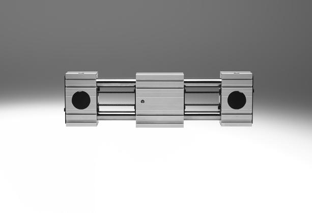
22 -V- New Toothed belt axes ELGR, for Optimised Motion Series (OMS) Type codes Type ELGR TB H ST E B AT FR ELGR Linear axis Drive function TB Toothed belt Guide Recirculating ball bearing guide Size Stroke [mm] Stroke reserve Slide Standard slide Motor type ST Stepper motor Measuring unit E Encoder Brake Without B With brake Cable outlet direction AT AD AL AR Top (standard) Underneath Left Right Motor position FR FL RL RR Front right (standard) Front left Rear left Rear right 22 Internet: Subject to change 206/05
23 -V- New Toothed belt axes ELGR, for Optimised Motion Series (OMS) Type codes + 2MA + 2.5E + C5 DIO N + DN Cover NC For mounting slot Slot nut NM For mounting slot Profile mounting MA Profile mounting Connecting cable to motor controller.5e.5 m, straight plug connector 2.5E 2.5 m, straight plug connector 5E 5 m, straight plug connector 7E 7 m, straight plug connector 0E 0 m, straight plug connector Controller type C5 CMMO, 5 A Bus protocol/activation DIO LK Digital I/O interface IO-Link Switching input/output N P NPN PNP Operating instructions With operating instructions DN Without operating instructions 206/05 Subject to change Internet: 23
24 -V- New Toothed belt axes ELGR, for Optimised Motion Series (OMS) Peripherals overview Internet: Subject to change 206/05
25 -V- New Toothed belt axes ELGR, for Optimised Motion Series (OMS) Peripherals overview Accessories Type/order code Description Page/Internet Slot cover NC 2 Centring sleeve ZBH 3 Profile mounting MA 4 Slot nut NM 5 Motor EMMS-ST 6 Axial kit EAMM 7 Encoder cable NEBM 8 Motor cable NEBM 9 Motor controller CMMO For protecting against ingress of dirt 42 For centring loads and attachments on the slide 42 2 centring sleeves included in the scope of delivery of the axis For mounting the axis on the bearing cap 4 For mounting attachments 42 Motors specially matched to the axis, with or without brake 38 For axial motor mounting (comprises: coupling, coupling housing and motor flange) 38 For connecting the encoder and controller 43 For connecting the motor and controller 43 For parameterising and positioning the toothed belt axis /05 Subject to change Internet: 25

26 -V- New Toothed belt axes ELGR, for Optimised Motion Series (OMS) Technical data Function -N- Size T- Stroke length mm -W- General technical data Size Design Electromechanical linear axis with toothed belt Guide Recirculating ball bearing guide Mounting position Any Standard stroke [mm] 50, 00, 50, 200, 250, 300, 350, 400, 450, 500, 550, 600, 650, 700, 750, , 00, 50, 200, 250, 300, 350, 400, 450, 500, 550, 600, 650, 700, 750, 800, 900, 000 Max. working load [kg] Max. feed force F x [N] Max. driving torque [Nm] Max. speed [m/s] Max. acceleration ) [m/s 2 ] 5 Repetition accuracy [mm] 0. 50, 00, 50, 200, 250, 300, 350, 400, 450, 500, 550, 600, 650, 700, 750, 800, 900, 000, 00, 200, 300, 400, 500 ) In combination with Optimised Motion Series (OMS). The max. acceleration is dependent on the payload, the driving torque and the max. feed force 29 Operating and environmental conditions Ambient temperature [ C] Degree of protection IP20 Duty cycle [%] Internet: Subject to change 206/05
27 -V- New Toothed belt axes ELGR, for Optimised Motion Series (OMS) Technical data Weight of axis/axial kit/motor [kg] Size Basic weight with 0 mm stroke ) Axis/axial kit/motor Additional weight per 000 mm stroke Moving mass Slide Standard slide ) Incl. slide Materials Sectional view Axis Bearing cap, profile Anodised wrought aluminium alloy 2 Guide rods Steel 3 Slide, profile Anodised wrought aluminium alloy 4 Toothed belt Polychloroprene with glass cord and nylon coating 5 Belt pulley High-alloy stainless steel Note on materials RoHS-compliant Contains paint-wetting impairment substances 206/05 Subject to change Internet: 27
28 -V- New Toothed belt axes ELGR, for Optimised Motion Series (OMS) Technical data Characteristic load values The indicated forces and torques refer to the centre of the guide. The point of application of force is the point where the centre of the guide and the longitudinal centre of the slide intersect. These values must not be exceeded during dynamic operation. Special attention must be paid to the cushioning phase. If the axis is subjected to two or more of the indicated forces and torques simultaneously, the following equation must be satisfied in addition to the indicated maximum loads: Calculating the load comparison factor: Fy,dyn Fz,dyn Mx,dyn My,dyn Mz,dyn f v Fy max. Fz max. Mx max. My max. Mz max. Permissible forces and torques for a service life of 5000 km Guide Recirculating ball bearing guide Size Fy max., Fz ) max [N] Standard slide Mx max. [Nm] My max. [Nm] Mz max. [Nm] ) In combination with Optimised Motion Series (OMS) max. working load limited only by drive system Service life The service life of the guide depends on the load. To provide a rough indication of the service life of the guide, the graph below plots the load comparison factor f v against the service life. These values are only theoretical. You must consult your local contact person at Festo for load comparison factors f v greater than.5. Load comparison factor f v as a function of service life Example: A user wants to move an X kg load. Using the above formula gives a value of.5 for the load comparison factor f v. According to the graph, the guide would have a service life of approx. 500 km. Reducing the acceleration reduces the Mz and My values. A load comparison factor of now gives a service life of 5000 km. 28 Internet: Subject to change 206/05
29 -V- New Toothed belt axes ELGR, for Optimised Motion Series (OMS) Technical data Feed force F x as a function of input torque M ELGR-35 ELGR-45 ELGR-55 Max. payload m as a function of acceleration a and speed v ) ELGR-35 ELGR-45 ELGR-55 5 m/s 2 0 m/s 2 5 m/s 2 ) In combination with Optimised Motion Series (OMS) 206/05 Subject to change Internet: 29
30 -V- New Toothed belt axes ELGR, for Optimised Motion Series (OMS) Technical data Max. payload m as a function of stroke l and positioning time t ) ELGR-35 ELGR-45 ELGR m 0.2 m 0.3 m 0.4 m 0.5 m 0.6 m 0.7 m 0.8 m 0.9 m.0 m. m.2 m.3 m.4 m.5 m Max. load with flat mounting position ) The characteristic curves in the graph correspond to the max. recommended deflection of 0.5 mm. In this case, the axis can no longer support the maximum load past a certain stroke length. ELGR-TB-35 ELGR-TB-45 ELGR-TB-55 ) In combination with Optimised Motion Series (OMS) max. working load limited only by drive system Second moment of area Y-axis Z-axis Size Iy [mm 4 ] 3.77x0 3.57x x0 4 Iz [mm 4 ].89x x0 5.85x0 6 Recommended deflection limits Adherence to a maximum deflection of 0.5 mm is recommended so as not to impair the functional performance of the axes. Greater deformation can result in increased friction, greater wear and reduced service life. 30 Internet: Subject to change 206/05
31 -V- New Toothed belt axes ELGR, for Optimised Motion Series (OMS) Technical data Dimensions Download CAD data + plus stroke + 2x stroke reserve Size B B2 B3 B4 B5 B6 B7 D H7 D2 D3 H Size D4 H7 H H2 H3 H4 H5 H6 H7 H8 H Size H0 H H2 H3 H4 H5 L L2 L3 L Size L5 L6 L7 L8 L9 L0 T T2 T3 n /05 Subject to change Internet: 3
32 -V- New Toothed belt axes ELGR, for Optimised Motion Series (OMS) Technical data Dimensions Profile ELGR-35 ELGR-45 ELGR-55 Download CAD data Size B2 B3 H3 H Size H5 H6 H Internet: Subject to change 206/05
33 -V- New Toothed belt axes ELGR, for Optimised Motion Series (OMS) Technical data Dimensions Motor attachment variants Download CAD data ELGR- -FL (motor at front left) 2 ELGR- -RL (motor at rear left) 3 ELGR- -RR (motor at rear right) 4 ELGR- -FR (motor at front right) Size H L L2 ELGR- ELGR- ELGR- -B -B -B /05 Subject to change Internet: 33
34 -V- New Toothed belt axes ELGR, for Optimised Motion Series (OMS) Ordering data Modular products Order code Mandatory data O top L left Centring holes on top and front U R underneath right V H front rear Motor attachment variants ELGR- -RR ELGR- -RL ELGR- -FL ELGR- -FR ELGR- -AR right ELGR- -AT top ELGR- -AL left ELGR- -AD underneath 34 Internet: Subject to change 206/05
35 -V- New Toothed belt axes ELGR, for Optimised Motion Series (OMS) Ordering data Modular product system Accessories NC 42 MA NM ST-E-B AT/AD/AL/AR FR/FL/RL/RR +.5E/+2.5E/+5E/+7E/+0E +C5-DIO-N/P -H- Note The associated axial kit ( 38) is automatically included in the scope of delivery. Motor and axial kit are installed on delivery. 206/05 Subject to change Internet: 35
36 -V- New Toothed belt axes ELGR, for Optimised Motion Series (OMS) Ordering data Modular product system Ordering table Size Conditions 0M Module no Code Entry code Design Linear axis ELGR ELGR Drive system Toothed belt -TB -TB Sizes Standard stroke [mm] 50, 00, 50, 200, 250, 300, 350, 400, 450, 500, 550, 600, 650, 700, 750, , 00, 50, 200, 250, 300, 350, 400, 450, 500, 550, 600, 650, 700, 750, 800, 900, , 00, 50, 200, 250, 300, 350, 400, 450, 500, 550, 600, 650, 700, 750, 800, 900, 000, 00, 200, 300, 400, 500 Stroke reserve [mm] 0 mm -0H -0H Slide design Standard slide Motor type Stepper motor -ST -ST Measuring unit Encoder -E -E Brake Without With brake B Cable outlet direction Top (standard) -AT Underneath -AD Left -AL Right -AR Motor position Front right (standard) -FR Front left -FL Rear left -RL Rear right -RR M O Mandatory data Options Transfer order code ELGR TB 0H ST E 36 Internet: Subject to change 206/05
37 -V- New Toothed belt axes ELGR, for Optimised Motion Series (OMS) Ordering data Modular product system Ordering table Size Conditions Code Entry code Accessories Accessories enclosed separately + + 0O Mounting slot cover 50 (=2pc. 500 mm long) NC Slot nut for mounting slot 99 NM Profile mounting 2 MA 0M Connecting cable to motor controller, suitable for use with Without.5 m, straight plug connector +.5E energy chains 2.5 m, straight plug connector +2.5E 5 m, straight plug connector +5E 7 m, straight plug connector +7E 0 m, straight plug connector +0E Controller type CMMO, 5 A +C5 +C5 Bus protocol/activation Digital I/O interface DIO IO-Link LK Switching input/output NPN N PNP P Operating instructions With operating instructions Without operating instructions +DN N Not with LK M O Mandatory data Options Transfer order code + + C /05 Subject to change Internet: 37
38 Accessories -H- Note Depending on the combination of motor and drive, it may not be possible to reach the maximum feed force of the drive. Permissible axis/motor combinations with axial kit Without gear unit Technical data Internet: eamm-a Motor ) Axial kit Axial kit comprises: Motor flange Coupling Coupling housing Type Part No. Type Part No. Type Part No. Type Part No. Type ELGR-35 With servo motor EMMS-AS EAMM-A-R27-55A EAMF-A-38A-55A EAMD X EAMK-A-R27-38A With stepper motor EMMS-ST-57-2) EAMM-A-R27-57A EAMF-A-38A-57A EAMD X EAMK-A-R27-38A With integrated drive EMCA-EC EAMM-A-R27-67A EAMF-A-38A-67A EAMD X EAMK-A-R27-38A ELGR-45 With servo motor EMME-AS EAMM-A-R38-60P EAMF-A-38A-60P EAMD X EAMK-A-R38-38A EMMS-AS EAMM-A-R38-70A EAMF-A-38A-70A EAMD X EAMK-A-R38-38A With stepper motor EMMS-ST EAMM-A-R38-57A EAMF-A-38A-57A EAMD X EAMK-A-R38-38A EMMS-ST-87-2) EAMM-A-R38-87A EAMF-A-38A-87A EAMD X EAMK-A-R38-38A ELGR-55 With servo motor EMMS-AS EAMM-A-R48-70A EAMF-A-48A-70A EAMD X EAMK-A-R48-48A EMME-AS EAMM-A-R48-80P EAMF-A-48A-80P EAMD X EAMK-A-R48-48A EMMS-AS EAMM-A-R48-00A EAMF-A-48A-00A EAMD X EAMK-A-R48-48A With stepper motor EMMS-ST-87-2) EAMM-A-R48-87A EAMF-A-48A-87A EAMD X EAMK-A-R48-48A ) The input torque must not exceed the maximum permissible transferable torque of the axial kit 2) Motors used in combination with Optimised Motion Series (OMS) 38 Internet: Subject to change 206/05
39 Accessories Permissible axis/motor combinations with axial kit With gear unit Technical data Internet: eamm-a Motor ) Gear unit Axial kit Axial kit comprises: Motor flange Coupling Coupling housing Type Part No. Type Part No.. Type Part No. Type Part No. Type ELGR-35 With servo motor EMME-AS-40- EMGA-40-P-G -EAS EAMM-A-R27-40G EAMF-A-38A-40G EAMD X EAMK-A-R27-38A EMMS-AS-40- EMGA-40-P-G -SAS EAMM-A-R27-40G EAMF-A-38A-40G EAMD X EAMK-A-R27-38A With stepper motor EMMS-ST-42- EMGA-40-P-G -SST EAMM-A-R27-40G EAMF-A-38A-40G EAMD X EAMK-A-R27-38A With integrated drive EMCA-EC-67- EMGC EAMM-A-R27-40G EAMF-A-38A-40G EAMD X EAMK-A-R27-38A ELGR-45 With servo motor EMME-AS-40- EMGA-40-P-G -EAS EAMM-A-R38-40G EAMF-A-38A-40G EAMD X EAMK-A-R38-38A EMMS-AS-40- EMGA-40-P-G -SAS EAMM-A-R38-40G EAMF-A-38A-40G EAMD X EAMK-A-R38-38A EMMS-AS-55- EMGA-60-P-G -SAS EAMM-A-R38-60G EAMF-A-38A-60G/H EAMD X EAMK-A-R38-38A EMME-AS-60- EMGA-60-P-G -EAS EAMM-A-R38-60H EAMF-A-38A-60G/H EAMD X EAMK-A-R38-38A EMMS-AS-70- EMGA-60-P-G -SAS EAMM-A-R38-60G EAMF-A-38A-60G/H EAMD X EAMK-A-R38-38A With stepper motor EMMS-ST-42- EMGA-40-P-G -SST EAMM-A-R38-40G EAMF-A-38A-40G EAMD X EAMK-A-R38-38A EMMS-ST-57- EMGA-60-P-G -SST EAMM-A-R38-60G EAMF-A-38A-60G/H EAMD X EAMK-A-R38-38A With integrated drive EMCA-EC-67- EMGC EAMM-A-R38-40G EAMF-A-38A-40G EAMD X EAMK-A-R38-38A EMGC EAMM-A-R38-60H EAMF-A-38A-60G/H EAMD X EAMK-A-R38-38A ) The input torque must not exceed the maximum permissible transferable torque of the axial kit 206/05 Subject to change Internet: 39
40 Accessories Permissible axis/motor combinations with axial kit With gear unit Technical data Internet: eamm-a Motor ) Gear unit Axial kit Axial kit comprises: Motor flange Coupling Coupling housing Type Part No. Type Part No.. Type Part No. Type Part No. Type ELGR-55 With servo motor EMMS-AS-55- EMGA-60-P-G -SAS EAMM-A-R48-60G EAMF-A-48A-60G/H EAMD X EAMK-A-R48-48A EMME-AS-60- EMGA-60-P-G -EAS EAMM-A-R48-60H EAMF-A-48A-60G/H EAMD X EAMK-A-R48-48A EMMS-AS-70- EMGA-60-P-G -SAS EAMM-A-R48-60G EAMF-A-48A-60G/H EAMD X EAMK-A-R48-48A With stepper motor EMMS-ST-57- EMGA-60-P-G -SST EAMM-A-R48-60G EAMF-A-48A-60G/H EAMD X EAMK-A-R48-48A With integrated drive EMCA-EC-67- EMGC EAMM-A-R48-60H EAMF-A-48A-60G/H EAMD X EAMK-A-R48-48A ) The input torque must not exceed the maximum permissible transferable torque of the axial kit 40 Internet: Subject to change 206/05
41 Accessories Profile mounting MUE (Order code MA) Materials: Anodised aluminium RoHS-compliant Dimensions and ordering data For size B B2 B3 D H H2 H3 H For size H5 L L2 L3 L4 Weight Part No. Type [g] MUE MUE MUE-45 Sensor bracket EAPM- -SHS, switch lug EAPM- -SLS (Order code SA/SB) Materials: Switch lug: Galvanised steel Sensor bracket: Wrought aluminium alloy, anodised RoHS-compliant EAPM-L4-SHS EAPM-L4-SLS Dimensions and ordering data For size B H L Weight Part No. Type [g] Sensor bracket 35, 45, EAPM-L4-SHS Switch lug 35, 45, EAPM-L4-SLS 206/05 Subject to change Internet: 4
42 Accessories Drive shaft EAMB Alternative interface (Order code EA) Forcing thread Dimensions and ordering data For size B B2 B3 D D2 D3 Weight Part No. Type [g] M EAMB-6-7-8X5-8X M EAMB-8-9-8X6-0X M EAMB X2-6X20 Ordering data For size Comment Order code Part No. Type PU ) Slot nut NST 35 For mounting slot NM NST-3-M3 45, NST-5-M5 Centring sleeve ZBH 2) 35, 45, 55 For slide 8677 ZBH-7 0 Slot cover ABP 45, 55 For mounting slot Every 0.5 m NC 568 ABP-5 2 ) Packaging unit 2) 2 centring sleeves included in the scope of delivery of the axis 42 Internet: Subject to change 206/05
43 Accessories Ordering data Proximity sensor for T-slot, inductive Type of mounting Electrical connection Switching output Technical data Internet: sies Cable length Order code Part No. Type [m] N/O contact Insertable in the slot from above, flush with the cylinder profile Cable, 3-wire PNP 7.5 SA SIES-8M-PS-24V-K-7,5-OE Plug connector M8x, 3-pin SIES-8M-PS-24V-K-0,3-M8D Cable, 3-wire NPN SIES-8M-NS-24V-K-7,5-OE Plug connector M8x, 3-pin SIES-8M-NS-24V-K-0,3-M8D N/C contact Insertable in the slot from above, flush with the cylinder profile Cable, 3-wire PNP 7.5 SB 5539 SIES-8M-PO-24V-K-7,5-OE Plug connector M8x, SIES-8M-PO-24V-K-0,3-M8D 3-pin Cable, 3-wire NPN SIES-8M-NO-24V-K-7,5-OE Plug connector M8x, 3-pin SIES-8M-NO-24V-K-0,3-M8D Ordering data Connecting cables Technical data Internet: nebu Electrical connection, left Electrical connection, right Cable length Part No. Type [m] Straight socket, M8x, 3-pin Cable, open end, 3-wire NEBU-M8G3-K-2.5-LE NEBU-M8G3-K-5-LE3 Angled socket, M8x, 3-pin Cable, open end, 3-wire NEBU-M8W3-K-2.5-LE NEBU-M8W3-K-5-LE3 Ordering data Cables ) For size Description Cable length [m] Part No. Type Motor cable Encoder cable 35 Straight plug connector Min. bending radius: 62 mm Suitability for energy chains Ambient temp.: C 45, 55 Straight plug connector Min. bending radius: 80 mm Suitability for energy chains Ambient temp.: C 35, 45, 55 Straight plug connector Min. bending radius: 68 mm Suitable for use with energy chains Ambient temp.: C NEBM-SG9-E-.5-Q5-LE NEBM-SG9-E-2.5-Q5-LE NEBM-SG9-E-5-Q5-LE NEBM-SG9-E-7-Q5-LE NEBM-SG9-E-0-Q5-LE NEBM-SG5-E-.5-Q7-LE NEBM-SG5-E-2.5-Q7-LE NEBM-SG5-E-5-Q7-LE NEBM-SG5-E-7-Q7-LE NEBM-SG5-E-0-Q7-LE NEBM-M2G8-E-.5-LE NEBM-M2G8-E-2.5-LE NEBM-M2G8-E-5-LE NEBM-M2G8-E-7-LE NEBM-M2G8-E-0-LE8 ) Other cable lengths on request. Ordering data Technical data Internet: cmmo Motor controller Description Part No. Type With I/O interface Switching input/output PNP 5236 CMMO-ST-C5--DIOP Switching input/output NPN 5237 CMMO-ST-C5--DION With IO-Link Switching input/output PNP CMMO-ST-C5--LKP 206/05 Subject to change Internet: 43
Toothed belt axes ELGG
 Key features At a glance Toothed belt axis with two opposing slides Optimum price/performance ratio Ready-to-install unit for quick and easy design High reliability thanks to a tested service life of 2500
Mini slides EGSL, electric
 Key features At a glance Electric slide series Maximum performance in compact space: Precision Load capacity Dynamic response Choice of homing: To fixed stop To reference switch Perfect for vertical applications
Toothed belt axes EGC-HD-TB, with heavy-duty guide
 Electromechanical drives Selection aid Overview of toothed belt and spindle axes Toothed belt axes Spindle axes Coordinate system Speeds of up to 10 m/s Acceleration of up to 0 m/s 2 Repetition accuracy
Spindle axes EGC-HD-BS, with heavy-duty guide
 Electromechanical drives Selection aid Overview of toothed belt and spindle axes Toothed belt axes Spindle axes Coordinate system Speeds of up to 10 m/s Acceleration of up to 50 m/s 2 Repetition accuracy
Guide axes ELFA, without drive
 Guide axes ELFA, without drive Guide axes ELFA, without drive Key features At a glance Driveless linear guide units with guide and freely movable slide The guide axis is designed to support force and torque
Toothed belt axes DGE
 Toothed belt axes DGE Toothed belt axes DGE Key features At a glance Precision, rigid guide Highly adaptable, thanks to wide choice of mounting and attachment options Wide range of options for attaching
Spindle axes ELGA-BS
 Spindle axes ELGA-BS Electromechanical drives Selection aid Overview of toothed belt and spindle axes Toothed belt axes Spindle axes Coordinate system Speeds of up to 10 m/s Acceleration of up to 50 m/s
Spindle axes DGE Key features
 Spindle axes DGE Spindle axes DGE Key features At a glance Precision, rigid guide Highly adaptable, thanks to wide choice of mounting and attachment options Wide range of options for attaching drive units
Linear drives DGC-HD, with heavy-duty guide
 Linear drives DGC Key features At a glance New heavy-duty design for: Maximum loads and torques thanks to duo rail guide Long service life Ideal as a basic axis for linear gantries and cantilever axes
Toothed belt axes ELGA-TB
 Toothed belt axes ELGA-TB q/w Worldwide: Superb: Easy: Festo core product range Covers 80% of your automation tasks Always in stock Festo quality at an attractive price Reduces procurement and storing
Positioning axes DMES
 Positioning axes DMES Positioning axes DMES Key features At a glance General Properties Range of applications DMES positioning axes are mechanical linear drives that are specially designed for movements
Electric slides EGSK/EGSP
 Electric slides EGSK/EGSP Electromechanical drives Selection aid Overview of toothed belt and spindle axes Toothed belt axes Spindle axes Coordinate system Speeds of up to 10 m/s Acceleration of up to
Rotary/lifting modules EHMB, electric
 Features At a glance The rotary/lifting module EHMB combines rotary and linear motion in one compact unit. The rotation is always transferred through a toothed belt to a hollow shaft by an electric motor
Rotary/lifting modules EHMB, electric
 Features At a glance The rotary/lifting module EHMB combines rotary and linear motion in one compact unit. The rotation is always transferred through a toothed belt to a hollow shaft by an electric motor
Toothed belt axes EGC-TB-KF, with recirculating ball bearing guide
 q/w Worldwide: Superb: Easy: Festo core product range Covers 80% of your automation tasks Always in stock Festo quality at an attractive price Reduces procurement and storing complexity qready for dispatch
Cantilever axes DGEA, with toothed belt drive
 Features Key features at a glance Super flat Ω drive head enabling high mechanical torques. High-quality guide as for DGE-KF/ DGP-KF axis. Improved dynamics compared to toothed belt axis DGE-ZR in cantilever
Guide units EAGF, for electric cylinders
 Guide units EAGF, for electric cylinders q/w Worldwide: Superb: Easy: Festo core product range Covers 80% of your automation tasks Always in stock Festo quality at an attractive price Reduces procurement
Mini slides SLTE, electric
 Key features Range of applications Special features The electric mini slide SLTE is ideal for use in automation applications where controlled end-position cushioning (gentle stopping), constant travel
Linear drives DGPL Selection aid
 Linear drives DGPL Linear drives DGPL Selection aid General Compact, fitting length relative to stroke Highly adaptable thanks to wide choice of mounting and attachment options Adjustable end-position
Rotary drives ERMO, electric
 q/w Worldwide: Superb: Easy: Festo core product range Covers 80% of your automation tasks Always in stock Festo quality at an attractive price Reduces procurement and storing complexity qready for dispatch
-V- New. Linear drives DGC Features. 2 Internet:
 Linear drives DGC Features At a glance Without external guide, for simple drive functions Compact fitting length relative to stroke Fully interchangeable with the linear drive DGP Easy assembly and installation
Electric cylinders EPCO, with spindle drive
 q/w Worldwide: Superb: Easy: Festo core product range Covers 80% of your automation tasks Always in stock Festo quality at an attractive price Reduces procurement and storing complexity qready for dispatch
Planar surface gantries EXCH
 Key features At a glance General Optimum dynamic response when compared with other Cartesian gantry systems The drive concept ensures low moving dead weight Flat system design Perfectly matched drive and
Linear drives DGC-K. Festo core product range Covers 80% of your automation tasks
 q/w Worldwide: Superb: Easy: Festo core product range Covers 80% of your automation tasks Always in stock Festo quality at an attractive price Reduces procurement and storing complexity qready for dispatch
Mini slides SLT/SLS/SLF
 Mini slides SLT/SLS/SLF Mini slides SLT/SLS/SLF Key features General information Double-acting drives Precise and rigid guide Versatile air connections Sensors can be integrated Highly flexible thanks
Passive guide axes DGC-FA, without drive
 Key features At a glance Driveless linear guide units with guide and freely movable slide The passive guide axis is designed to support force and torque capacity in multi-axis applications Higher torsional
Planar surface gantries EXCM
 Planar surface gantries EXCM Planar surface gantries EXCM Features At a glance General remarks Sample applications A gantry that is characterised by high functionality in compact installation spaces The
Three-dimensional gantries
 Key features At a glance A three-dimensional gantry (YXCR) is an assembly of several axis modules (EHM /DHMZ) to produce a movement in 3D space. Can be used universally for handling light to very heavy
Linear gantries Key features
 Key features At a glance A linear gantry (YXCL) is an assembly of several axis modules (EHM /DHMZ) to produce a movement in 2D space. Ideal for long gantry strokes and heavy loads High mechanical rigidity
Motion without compromise
 Toothed belt and spindle axes ELGA Clean, protected, strong Motion without compromise Highlights Protected: insensitive to harsh ambient conditions Clean: virtually no particle emissions for use in cleanrooms
Mini slides SLT/SLS/SLF
 Mini slides SLT/SLS/SLF Mini slides SLT/SLS/SLF Key features General information Double-acting drives Precise and rigid guide Versatile air connections Sensors can be integrated Highly flexible thanks
Linear gantries Key features
 Key features At a glance A linear gantry (YXCL) is an assembly of several axis modules (EHM /DHMZ) to produce a movement in 2D space. The linear gantry facilitates movement in 2D space. Depending on the
-U- Type discontinued
 Key features At a glance -V- New Sturdier Optimised end stop system Optimised intermediate position module Minimised susceptibility to wear One-way flow control valves that can be externally adjusted Integrated
Mini slides DGSL. Festo core product range Covers 80% of your automation tasks
 q/w Worldwide: Superb: Easy: Festo core product range Covers 80% of your automation tasks Always in stock Festo quality at an attractive price Reduces procurement and storing complexity qready for dispatch
Simplicity. Easy for you!
 Optimized Motion Series Simplicity Highlights Easy Select the axis to best meet your application needs Order using a single type code All axis components delivered together fast Save time Configure positions
3 Electromechanical drives
 Electromechanical drives 2015/11 Subject to change www.festo.com/catalogue/... 49 Electromechanical drives > Linear drives and slides Semi-rotary drives Electric handling modules Direct drives Accessories
Toothed belt and ball screw actuator EGC/EGC-HD
 Toothed belt and ball screw actuator EGC/EGC-HD Power unit! Highlights Rigid: optimised aluminium profile for handling very high torques and forces Efficient: optimally sized drive solution using PositioningDrives
Rack and pinion axis EHMH
 Features At a glance Right-angle gear unit with a reduction ratio of i = 5 High-grade bearing guide Comprehensive accessories for individual adaptation to specific requirements Use of time-tested motorcontroller
Guided drives DFM/DFM-B
 Guided drives DFM/DFM-B q/w Worldwide: Superb: Easy: Festo core product range Covers 80% of your automation tasks Always in stock Festo quality at an attractive price Reduces procurement and storing complexity
Slide units SPZ, twin piston
 Key features Multi-axis and drive combinations The slide unit SPZ can be combined with different drives. An adapter kit is required for mounting between the two drives. DPZ-/SPZ axis Adapter kits www.festo.com
Linear drives DGC Key features
 Linear drives DGC Linear drives DGC Key features General information Compact fitting length relative to stroke Loads and devices can be directly mounted on the slide Three types of cushioning available:
Single-axis systems Key features
 Key features At a glance A single-axis system (YXCS) is an axis module (EHM ) for any single-axis movement. Ideal for long gantry strokes and heavy loads High mechanical rigidity and sturdy design Use
Linear drives SLG, flat design
 Features General information Piston 8, 12 and 18 Stroke lengths of 100 900 mm Two cushioning types selectable: Elastic cushioning Shock absorbers Direct mounting via centering holes Extremely flat design
Feed separators HPVS
 Key features and peripherals overview At a glance 1 Corrosion-resistant thanks to stainless steel plunger 2 Optimum and precise adaption options using centring sleeves 3 Supply ports optionally on top
Guided drives DFM/DFM-B
 Guided drives DFM/DFM-B q/w Worldwide: Superb: Easy: Festo core product range Covers 80% of your automation tasks Always in stock Festo quality at an attractive price Reduces procurement and storing complexity
Planar surface gantries
 Key features At a glance The planar surface gantry facilitates movement in 2D space. Depending on the requirements, the gantry is either composed of several axis modules (YXCF) or using the planar surface
Linear drives DGPL Selection aid
 Linear drives DGPL Linear drives DGPL Selection aid General Compact, fitting length relative to stroke Highly adaptable thanks to wide choice of mounting and attachment options Adjustable end-position
Parallel grippers HGPL-B, heavy-duty with long stroke
 Key features At a glance Sturdy The T-slot in combination with the long guide length allows for high forces and torques Space-saving Two parallel and opposing pistons move the gripper jaws directly and
Linear drives DGP/DGPL
 Linear drives DGP/DGPL Low space requirement High precision and load capacity Reliable service life of up to 40,000 km Specified types in accordance with ATEX directive for potentially explosive atmospheres
-U- Type discontinued. -H- Note. Available up until Angle grippers HGWC Key features
 Key features At a glance General information The compact and cost-optimised angle gripper consists of a two-part mirrorsymmetrical housing made of die-cast zinc. The force generated by the linear motion
Linear drives DGC. Festo core product range Covers 80% of your automation tasks
 Linear drives DGC q/w Worldwide: Superb: Easy: Festo core product range Covers 80% of your automation tasks Always in stock Festo quality at an attractive price Reduces procurement and storing complexity
-H- Note. Feed separators HPV Key features at a glance. Separation of workpieces in the supply process
 Key features at a glance Separation of workpieces in the supply process Previously Required at least 2 drives, 2 valves and 4 proximity sensors Extensive programming required Today One unit (1 drive, 1
Radial grippers DHRS
 Key features At a glance General information Flexible range of applications Lateral gripper jaw support for high torque loads Self-centring Gripper jaw centring options Max. repetition accuracy Gripping
Radial grippers DHRS
 Key features At a glance General information Flexible range of applications Lateral gripper jaw support for high torque loads Self-centring Gripper jaw centring options Max. repetition accuracy Gripping
Linear gantries EXCT
 Key features At a glance General Optimal dynamic response when compared with other Cartesian gantry systems The drive concept ensures low moving dead weight Flat system design Perfectly matched drive and
Three-point grippers DHDS
 Key features At a glance General information Flexible range of applications Resilient and precise T slot guide of the gripper jaws High gripping forces with compact dimensions Gripper jaw centring options
Parallel grippers DHPS
 Key features At a glance General information Flexible range of applications Resilient and precise T slot guide of the gripper jaws Oval piston for high gripping forces High gripping forces with compact
Three-dimensional gantries
 Key features At a glance A three-dimensional gantry (YXCR) is an assembly of several axis modules (EHM /DHMZ) to produce a movement in 3D space. Can be used universally for handling light to very heavy
Compact! Spindle and toothed belt axes ELGC and mini slides EGSC. Maximum use of space
 Spindle and toothed belt axes ELGC and mini slides EGSC Maximum use of space Compact! Highlights Very compact and costefficient Optimal installation space to working space ratio Unique one-size-down assembly
Handling modules HSP
 Handling modules HSP Handling modules HSP Key features at a glance Field of application Special features The handling module is a new generation of function modules for the automatic transfer, feed and
Stepper motors EMMS-ST
 q/w Worldwide: Superb: Easy: Festo core product range Covers 80% of your automation tasks Always in stock Festo quality at an attractive price Reduces procurement and storing complexity qready for dispatch
Twin-piston semi-rotary drives DRRD
 Twin-piston semi-rotary drives DRRD q/w Worldwide: Superb: Easy: Festo core product range Covers 80% of your automation tasks Always in stock Festo quality at an attractive price Reduces procurement and
Stepper motors EMMS-ST
 q/w Worldwide: Superb: Easy: Festo core product range Covers 80% of your automation tasks Always in stock Festo quality at an attractive price Reduces procurement and storing complexity qgenerally ready
Semi-rotary drives DRQ
 Features 40 100 mm 16 32 mm Rotating and swivelling The linear movement of the cylinder is converted into rotational movement by a backlash-compensating gear unit. Precision is increased by backlashfree
-H- Note. Angle grippers HGWC Key features. 2 Internet:
 Key features At a glance General information The compact and cost-optimised angle gripper consists of a two-part mirrorsymmetrical housing made of die-cast zinc. The force generated by the linear motion
Twin-piston semi-rotary drives DRRD
 Twin-piston semi-rotary drives DRRD Twin-piston semi-rotary drives DRRD Key features At a glance Rack and pinion principle Very high accuracy in the end positions Very high bearing load capacity Very good
Linear/swivel clamp CLR
 Key features Functional description The linear/swivel clamp CLR is used for all types of clamping. Through the combination of the linear and swivel motion of the piston rod, it is possible to insert and
Accessories for electrical positioning systems
 Accessories for electrical positioning systems Accessories for electrical positioning systems Features At a glance Bellows couplings EAMC-B page 3 One-piece coupling with threaded pin locking, suitable
Swivel modules DSM/DSM-B
 Swivel modules DSM/DSM-B Swivel modules DSM/DSM-B Key features At a glance Double-acting swivel module with rotary vanes The swivel angle is infinitely adjustable over the entire swivel range High precision
Semi-rotary drives DRVS
 Key features Key features at a glance Double-acting semi-rotary drive with rotary vanes Lighter than other semi-rotary drives Modern and compact design Fixed swivel angle Swivel angle can be adjusted with
Linear drives SLM, with guided slide
 Key features Version The linear drive SLM is a combination of a slide unit and a rodless linear drive. The drive moves the slide. The transmission of movement is accomplished via a magnetic coupling. The
-U- Type discontinued. -H- Note. Available up until Angle grippers HGW Key features. 2 Internet:
 Key features At a glance Double-acting piston drive Self-centring Variable gripping action: External/internal gripping Versatility thanks to externally adaptable gripper fingers Wide range of options for
Compact cylinders ADN-S, AEN-S
 Compact cylinders ADN-S, AEN-S Compact cylinders ADN-S, AEN-S Key features At a glance Without sintered bearing Free of copper Improved operating behaviour Due to precise manufacturing from a single piece
Swivel/linear drive units DSL-B
 Key features At a glance High repetition accuracy thanks to cushioning components with fixed stop Swivel angle can be infinitely and accurately set The mechanical gearing between the stop element and swivel
DGE Linear Actuators. Belt and Ball Screw Driven. Info 130 US
 DGE Linear Actuators Belt and Ball Screw Driven Belt Driven Linear Actuators Sizes: 8, 12, 18, 25, 40, 63 Stroke Lengths up to 5 m Maximum Speed: 10 m/s Repeatability of ±0.10 mm Axial force up to 1,500
Twin cylinders DPZ/DPZJ
 Key features High force with excellent protection against torsion 100 to 1,000 N thrust at 6 bar operating pressure Load capacity (F q ) from 8 to 105 N F q max. Permissible torque load (T L ) centrally
Parallel grippers HGP, with protective dust cap
 Key features At a glance Double-acting piston drive With protective dust cap for use in dusty environments (protection class IP54) Self-centring Variable gripping action: External/internal gripping High
Spindle axis ELGC-BS-KF. Operating instructions [ ]
![Spindle axis ELGC-BS-KF. Operating instructions [ ]](/thumbs/87/97202885.jpg "Spindle axis ELGC-BS-KF. Operating instructions [ ]") Spindle axis ELGC-BS-KF en Operating instructions 8067243 2017-01 [8067245] Original instructions Identification of hazards and instructions on how to prevent them: Danger Immediate dangers which can lead
Spindle axis ELGC-BS-KF en Operating instructions 8067243 2017-01 [8067245] Original instructions Identification of hazards and instructions on how to prevent them: Danger Immediate dangers which can lead
ELGC-BS-KF. Spindle axis. Instructions Operating c [ ]
![ELGC-BS-KF. Spindle axis. Instructions Operating c [ ]](/thumbs/88/115778972.jpg "ELGC-BS-KF. Spindle axis. Instructions Operating c [ ]") ELGC-BS-KF Spindle axis Instructions Operating 8095590 8095590 2018-08c [8095592] Translation of the original instructions 2 Festo ELGC-BS-KF 2018-08c Table of contents 1 Further applicable documents...
ELGC-BS-KF Spindle axis Instructions Operating 8095590 8095590 2018-08c [8095592] Translation of the original instructions 2 Festo ELGC-BS-KF 2018-08c Table of contents 1 Further applicable documents...
Toothed belt axis ELGC-TB-KF. Operating instruction [ ]
![Toothed belt axis ELGC-TB-KF. Operating instruction [ ]](/thumbs/83/87984161.jpg "Toothed belt axis ELGC-TB-KF. Operating instruction [ ]") Toothed belt axis ELGC-TB-KF en Operating instruction 8068220 2017-02 [8068222] Original instructions Identification of hazards and instructions on how to prevent them: Danger Immediate dangers which can
Toothed belt axis ELGC-TB-KF en Operating instruction 8068220 2017-02 [8068222] Original instructions Identification of hazards and instructions on how to prevent them: Danger Immediate dangers which can
Mechatronic Motion Solutions
 Mechatronic Motion Solutions Mechatronic Motion Solutions from Festo is a worldwide unique system comprising components, modules and software. It combines all types of pneumatic, servopneumatic and (electro-)mechanical
Stopper cylinders DFSP
 Key features At a glance Versions: Trunnion Trunnion with female thread Roller Single-acting, pulling Double-acting with spring, pulling Double-acting without spring With or without protection against
ELECTRIC AXIS ELEKTRO SVAK SERIES ACTUATORS
 ELECTRIC AXIS ELEKTRO SVAK SERIES 1 ELECTRIC AXIS ELEKTRO SVAK SERIES This belt-driven rodless electric actuator is characterised by the fact that the motor and reducer unit is integral with the carriage,
Mini slide EGSC-BS-KF. Operating instructions b [ ]
![Mini slide EGSC-BS-KF. Operating instructions b [ ]](/thumbs/87/95253800.jpg "Mini slide EGSC-BS-KF. Operating instructions b [ ]") Mini slide EGSC-BS-KF en Operating instructions 8081968 2017-11b [8081970] Translation of the original instructions EGSC-BS-KF-EN Identification of hazards and instructions on how to prevent them: Danger
Mini slide EGSC-BS-KF en Operating instructions 8081968 2017-11b [8081970] Translation of the original instructions EGSC-BS-KF-EN Identification of hazards and instructions on how to prevent them: Danger
Linear actuators DFPI
 Linear actuators DFPI Linear actuators DFPI Key features General information Linear actuator for actuating process valves such as gate valves and shut-off valves in process automation systems Linear actuator
Electric cylinders ESBF, with spindle drive
 q/w Worldwide: Superb: Easy: Festo core product range Covers 80% of your automation tasks Always in stock Festo quality at an attractive price Reduces procurement and storing complexity qready for dispatch
Long stroke grippers HGPL
 Sturdy Gripping forces of up to 754 N Reliable Space saving 2004/10 Subject to change Products 2004/2005 1 / 3 Key features At a glance Space saving and suitable for high forces Two parallel and opposing
Rotary indexing tables DHTG
 Key features At a glance Sturdy mechanical system Easy planning and commissioning Indexing: 2, 3, 4, 6, 8, 12, 24 Integrated functions: Overload protection Sensor function Cushioning adjustment Speed setting
Linear drives DGPL, with external displacement encoder
 Linear drives DGPL, with external displacement encoder Cylinders with displacement encoder Product range overview Function Type Description Drives Rodless DDLI Without guide With contactless measuring
Guided drives DGRF-C, Clean Design
 Features and Product range overview At a glance The guided drive is used wherever hygiene, ease of cleaning and resistance are important, predominantly in dry and splash zones in the food and packaging
Hinge cylinders DFAW
 Key features At a glance Hinge cylinder for clamping components during the welding process Sintered bronze bushes as lowfriction bearing material on rod clevis and swivel bearing Clamping unit: With piston
Linear Drive with Toothed Belt and Integrated Guide with Recirculating Ball Bearing Guide with Roller Guide Series OSP-E..BHD
 Linear Drive with and Integrated Guide with Recirculating Ball Bearing Guide with Roller Guide Contents Description Page Overview 11-14 Version with Recirculating Ball Bearing Guide Technical Data 15-17
Index. -V- New. -N- Diameters. -T- Stroke lengths. Pneumatic linear drive units DGP/DGPL Key features at a glance Festo AG & Co.
 Index Key features at a glance 3 4 7 6 2 1 5 DGP with driver DGPL with slide -V- New Protected version GA with shock absorber kit E Version free of copper, Teflon and silicone CT Load inverter AK -N- Diameters
Hinge cylinders DW Key features
 Key features At a glance Hinge cylinder for clamping components during the welding process Easy assembly thanks to swivel bearing on the bearing cap Integrated flow control Integrated end-position cushioning
Compact systems! Ball screw and toothed belt axes ELGC and mini slides EGSC. Modular and low cost
 Ball screw and toothed belt axes ELGC and mini slides EGSC Modular and low cost Compact systems! Highlights Compact, lightweight systems Low cost solutions Modular axes easily assembled into multi-axis
Proximity sensors SMT/SME-10, for C-slot
 Proximity sensors SMT/SME-10, for C-slot Proximity sensors SMT/SME Product range overview Design Type of mounting Measuring principle Type Operating voltage range For C-slot Standard Insertable in slot
-H- Note. Feed separators HPV Key features at a glance. Separation of workpieces in the supply process
 Key features at a glance Separation of workpieces in the supply process Previously Required at least 2 drives, 2 valves and 4 proximity sensors Extensive programming required Today One unit (1 drive, 1
Parallel grippers HGPC
 Key features At a glance General The compact and low-cost parallel gripper consists of a two-part symmetrical housing. The piston moves traverse to the half-shell casing in an optimum housing design that
A5 BELT-DRIVEN RODLESS ELECTRIC AXIS, SERIES ELEKTRO BK
 BELT-DRIVEN RODLESS ELECTRIC AXIS, SERIES ELEKTRO BK Belt-driven rodless electric axis with a V-Lock interface. The structure features an extremely lightweight yet high-strength anodised aluminium extruded
Vertical Linear Drive with Toothed Belt and Integrated Recirculating Ball Bearing Guide Series OSP-E..BV
 Vertical Linear Drive with Toothed Belt and Integrated Recirculating Ball Bearing Guide Series OSP-E..BV Contents Description Page Overview 25-28 Technical Data 29-33 Dimensions 34 Order Instructions 35