CARAVAN CHASSIS HANDBOOK FOR VEHICLES ON THE AL-KO CARAVAN CHASSIS
|
|
|
- Blaze Cole
- 5 years ago
- Views:
Transcription
1 CARAVAN CHASSIS HANDBOOK FOR VEHICLES ON THE AL-KO CARAVAN CHASSIS
2 AL-KO CARAVAN CHASSIS GENERAL INFORMATION The AL-KO lightweight chassis has been perfected by many years of research and development, supported by an exhaustive test programme. Manufactured from high quality steel, the chassis has extra deep sections to provide strength at points of maximum stress. Large elongated holes are punched in the longitudinal chassis members, to reduce weight to a minimum. Each hole incorporates a return flange to maintain the required strength and provide rigidity in the extra deep sections. AL-KO does not recommend the removal of standard fit accessory products to allow fitment of third party products and cannot be held responsible should the removal and subsequent fitment of third party products causes damage to the chassis components. The process of fitting third party products to the AL-KO Chassis therefore may invalidate the chassis warranty. The chassis frame is of a bolted construction which allows replacement of individual parts should the need arise. AL-KO Chassis and axles are manufactured with the fixing positions for a range of chassis accessories already included. Some of these accessories are included as standard from the vehicle manufacturer and are positioned for correct and safe usage of these products. For further details on the range of accessory products that can be fitted and used with the AL-KO Chassis, please refer to the Accessories section at the rear of this document, pages
3 AL-KO CARAVAN CHASSIS HOT DIP GALVANISATION The chassis is Hot Dipped Galvanised. This is regarded as one of the best forms of corrosion protection. It does however require minimal maintenance in certain circumstances. When new, the chassis is of a bright and shiny appearance. As the galvanising cures during the initial 2/ 3 month period, this will gradually change to a medium/dark grey colour. This grey finish is the ideal, giving the correct protective coating. During this curing period the surface should be protected to avoid possible wet storage stain, in the form of a soft, light coloured, porous, oxidation layer. If the chassis members are in contact with any salt deposits from roads this should immediately be washed off with a high pressure washer. Salt attracts moisture allowing the surfaces to remain wet, this prevents curing and also allows formation of wet storage stain. The galvanised chassis should not be painted or subjected to any other protective treatment. Should the galvanising become superficially damaged exposing the steel core, this should be cleaned and treated with a Cold Galvanising Spray obtainable from vehicle accessory outlets. Damage to chassis members through impact etc, MUST NOT be straightened or welded. Damaged chassis members MUST be replaced. It is recommended that the chassis/ components are washed off, using a pressure washer on an annual basis (especially after winter usage), to avoid undesirable build up of salt and dirt deposits. 3
. Failure to comply will invalidate all warranties.")
4 AL-KO CARAVAN CHASSIS DRILLING OR WELDING OF PARTS OR ACCESSORIES The chassis is designed and built to precise tolerances and must not be drilled or welded (except in accordance with certain AL-KO Accessory Operating Instructions). Failure to comply will invalidate all warranties. INDEPENDENT SUSPENSION The AL-KO rubber suspension is designed and developed to suit all types of road conditions and is maintenance free. Three rubber elements are contained within a hexagonal axle tube. These provide suspension and have inherent damping characteristics. (Only the hubs and wheel brakes require attention - see axle section). LOADINGS ON COUPLING HEADS, OVERRUN ASSEMBLIES AND AXLES The permitted nose weights of the coupling head/stabiliser, overrun assembly and drawbars, must never exceed the lowest value stamped on the assemblies. The maximum axle loading is that stamped on the plate located in the centre of the axle, facing rearwards. The plate will be one of the three shown below - Figs 1, 1a and 2, depending on date and location of manufacture. The line marked Capacity (on German plates Achlast ) is the maximum permitted axle loading and must not be exceeded. Where the Caravan Manufacturer states a maximum loading weight, then this is the maximum permitted load. This figure must not exceed the maximum axle load. AL-KO TYPE LE CAPACITY kg 25km/h TYP A ACHLAST EA TA MOD. AL-KO kg kg Fig 1 Axle Identification Plate Fig 1a New Axle Identification Plate Fig 2 Axle Identification Plate (German) 4
5 AL-KO CARAVAN CHASSIS LOADING Loads to be carried in the caravan should be placed directly over, or as close as possible to the axles, otherwise the handling will be impaired. Maximum gross weight, as advised by the caravan manufacturer, must not be exceeded without approval from AL-KO. Maximum loading is defined as the difference between ex-works weight and the permitted total weight. Attention should be paid to the legal regulations regarding the permitted pressure exerted by the towbar on the towed unit. Fig 3 Load Too Far Forward Steering and braking ability reduced. Increased loading on the rear axle and chassis of the tow vehicle. Fig 4 Load Too Far Back High skid risk together with poor braking effect. Fig 5 Load Over Axle Optimum road holding together with maximum braking effect. Exceptionally heavy loads should be packed directly over the axle. 5
6 AXLE TYPES SAFETY PRECAUTIONS No welding is permitted on AL-KO Axles. It is important that the wheel and hub/brake drum are compatible. This means that the PCD, wheelbolts and inset must all be compatible with both the hub/brake drum and the wheel rim. Particular attention must be paid to the recommended torque figures for the wheelbolts (page 12). The axle type details shown on axle type plates must not be obscured or made illegible by application of any additional surface finish. OPERATING INSTRUCTIONS Service Brake When the towing vehicle is braking or travelling down hill, the overrun device shaft is pushed in (dependent on the magnitude of the thrust on the shaft) and presses on the overrun lever. This acts on the Bowden cables and expander mechanism, which in turn expands the brake shoes applying the wheel brakes. Reversing When the towing vehicle is reversing, the overrun device shaft is pushing in, applying the brakes via the overrun lever, brake rod system, Bowden cables and the expander mechanism. The backwards rotation of the brake drum causes the secondary brake shoe to collapse cancelling out the braking effect, allowing the trailer to move backwards. At the same time the transmission lever swings back and compensates for the entire travel. Hand Brake With the Euro Hand Brake, pull the lever until upright. The caravan is then braked. IMPORTANT NOTE Please note that with the handbrake fully applied, the caravan/ trailer is able to move backwards by 25 cm until the spring cylinder/gas spring takes effect. 6
7 AXLE TYPES MAINTENANCE AND CLEANING Maintenance of Euro-Plus/Euro- Compact and Euro-Delta. The above semi-trailing axles come fitted with maintenance free wheel bearings (greased and sealed for life) and no adjustment is necessary. NOTE The hub bearing is not protected against water ingress. Check wheel brake linings for wear every 10,000 kilometres or every 12 months via the inspection hole (Fig 6/Item 1). Adjust if necessary. Where continuous travel in hilly regions or high mileage is experienced, earlier inspection and adjustment may be necessary. 1 NOTE The flanged hub-nut, located under the dust cap, used to keep the brake drum in situ, is a ONE-SHOT NUT (ie. must only be used once). If removed it must be replaced with a NEW flanged nut - torqued to 290 ± 10 Nm (214 ± 7.5 lbs/ft). A small amount of special mineral grease, available from AL-KO must be applied to stub axle thread prior to fitting the new flanged nut. After fitting excess grease must be removed with white spirit. The rear hexagon cap head bolt MUST NOT BE DISTURBED under any circumstances. Interference with this nut will result in immediate tyre wear and damage to the braking system and WILL INVALIDATE ALL WARRANTIES. Should the rear nut accidentally be disturbed then the complete axle must be returned to AL-KO for resetting of the toe-in and camber. No attempt should be made to remove the bearing. In the event of damage to the bearing or drum, only the drum complete with bearing and circlip will be available as a spare. No grease is used in the hub other than the mineral grease on the stub axle. No grease should be placed in the DUST cap. This is not a grease cap as used in all previous hubs Fig 6 Checking wheel brake linings for wear via inspection holes 7
8 AXLE TYPES STANDARD AXLE MAINTENANCE (TAPER ROLLER BEARINGS) After 1500 km or 6 months Have the axial play of the hub bearing checked and adjusted if necessary. After 10,000 km or 12 months Check quantity and quality of grease, renew if necessary. With boat trailers which are driven into fresh/salt water, the hub bearing should be regreased shortly after contact with the water (with the exception of waterproof hubs). Check the wear of the wheel brake linings every 10,000 km or every 12 months through inspection hole (Fig 6) and adjust if necessary. Where continuous travel in hilly regions or high mileage is experienced, earlier inspection and adjustment may be necessary. SPARE PARTS Spare parts are safety critical parts! For this reason when fitting spare parts in our products we recommend the use of original AL-KO parts or those parts that we have explicitly approved. The reliability, safety and suitability of parts designed especially for our products, has been determined using a special test procedure. In spite of constantly monitoring the market we are unable to assess or vouch for other products. If repair work or servicing is required, AL-KO have a large network of AL-KO service stations throughout Europe. To establish the correct spare parts required for your axle you should always quote the axle type (axle identification plate Figs 1/2) and Spare Part Identification no. (ETI No.), which will be stamped onto the wheel brake or identification plate (Fig 7). Please establish these numbers before contacting AL-KO or a Service Agent. STANDARD AXLE MAINTENANCE (SEALED FOR LIFE BEARINGS) AL-KO Wheel Hubs are fitted as standard with Sealed For Life bearings which are maintenance free. 8
9 AXLE TYPES ETI No Fig 8 Rebound or Free Position Fig 7 Spare Part Identification Number The AL-KO rubber suspension axle has been designed & developed to suit all types of road conditions and is maintenance free. Three rubber elements are contained within an hexagonal axle tube. These provide suspension and have inherent damping characteristics. Fig 9 Normal Laden Position Figs 8, 9 & 10 show the deformation of the rubber elements at the extremes of suspension movement. The axle is designed to ride with the suspension drop arm at, or slightly below, the horizontal position. For Trouble Shooting & Fault Finding see Table 1 on page 46. Fig 10 Maximum Bump 9
10 AL-KO BRAKING SYSTEM ADJUSTMENT Ensure the towing shaft with coupling head is pulled FULLY FORWARD. (Fig 11). 2. Release the handbrake to the FULLY OFF position. If the handbrake will not go down the whole way because of the fairing or any other obstruction; then the fairing must be cut away and/or the obstruction removed to achieve this desired position. It will not be possible to set up the braking system properly when the handbrake is not in the FULLY OFF position. (Fig 11). 3. Jack up one side of the caravan, using the AL-KO Side Lift Jack System. (See Jack Operating Instructions). 4. Remove the inner plastic bung from the backplate to expose the starwheel adjuster access. (Figs 11 & 12). 5. ALWAYS rotating the road wheel in the forward direction - NEVER backwards; adjust the starwheel with a suitable screwdriver, in the direction of the arrow embossed on the backplate until there is resistance in the wheel rotation. (Fig 12). 6. Slacken off the starwheel adjuster until the road wheel turns freely in the FORWARD direction. (Fig 12). 7. Check the adjustment at the end of the brake cable where it is secured to the abutment (bracket), welded to the centre of the axle. When the inner cable is pulled out it should extend between 5 and 8 mm. (Fig 13a\b). (On tandem axles a double abutment (bracket) is fitted to the front axle ONLY). 8. Repeat for other wheel or wheels. 9. On tandem axles the brake cables from the rear axle should pass over this axle and cross over each other before being connected to the abutment (bracket) on the front axle. Where ATC is fitted to a tandem axle caravan, the brake cables SHOULD NOT be crossed over. 10. Ensure the balance bar (compensator) is being pulled evenly (Figs 11 & 13a\b). Excessive movement to this bar (double on tandem axles) would indicate possible incorrect adjustment (if appropriate, repeat step No. 7 - Fig 13a\b). 11. Check the brake rod support bracket, (fixed to the floor) IS supporting the brake rod evenly. The brake rod MUST ALWAYS run straight, NEVER bent or curved under any fittings. On tandem axles, using the double balance bar, a brake rod support tube (Part No ) MUST ALWAYS be fitted on the end of the brake rod, passing through the centre aperture on the abutment.
11 AL-KO BRAKING SYSTEM ADJUSTMENT Fig 11 Brake Linkage 1 Fig 12 Adjusting the Starwheel 11
12 AL-KO BRAKING SYSTEM ADJUSTMENT PRE-2016 MODELS Before proceeding check the year of caravan manufacture. For caravans manufactured up to and including 2015 season, proceed as detailed below in steps 12a For caravans manufactured season 2016 onwards, turn to page 14 and follow steps 12b a - Valid for up to and including 2015 season chassis. Remove the slack in the brake rod by adjusting the long ball nut, rear of the balance bar (compensator), ensuring the overrun lever makes contact with the end of the towing shaft. Note! Over adjustment to the long ball nut (Fig 13/Item 2) could induce movement of the inner brake cable, reducing the effective clearance of the brake shoes. If the overrun lever will not make contact, it is possible the two lock nuts, forward of the spring cylinder (if fitted), are incorrectly adjusted. Loosen the nuts and adjust brake rod as above (Figs 11, 13a\b). 14. When parking, the handbrake lever MUST ALWAYS be engaged into the fully upright position (90 ). If difficulty is experienced in this operation, try easing the caravan backwards with one hand while engaging the handbrake fully with the other. This manoeuvre should not be attempted on a rearwards facing slope. In this case wheel chocks should be used combined with the handbrake. 15. Finally, if the road wheels have been removed, re-tighten all M12 wheel bolts, in sequence to the manufacturer s specifications, using a calibrated Torque Wrench. Remember that to over-tighten is just as dangerous as to under-tighten, as this can distort the wheel rims. Avoid the use of power wrenches. IMPORTANT The torque settings should be rechecked after 50 km. 13. OVER ADJUSTMENT of either the wheel brakes or linkages, will result in difficult reversing causing the wheels to lock-up. 12
13 AL-KO BRAKING SYSTEM ADJUSTMENT PRE-2016 MODELS Balance bar Axle Bowden Cable Abutment (welded to axle tube) 1- Brake rod 2- M10 Ball nut M10 Locknut Bowden Cables Fig 13a Standard Brake Linkage Balance bar Axle Bowden Cable Abutment (welded to axle tube) ATC Guide Tube ATC Mounting Bracket 1- Brake rod 2- M10 Ball nut ATC Push Rod 4- Bowden Cables Fig 13b Brake Linkage with ATC Fitted 13
14 AL-KO BRAKING SYSTEM ADJUSTMENT 2016 MODELS ONWARDS Before proceeding check the year of caravan manufacture. For caravans manufactured up to and including 2015 season, proceed as detailed below in steps 12a For caravans manufactured season 2016 onwards, turn to page 14 and follow steps 12b b - Valid for season 2016 chassis onwards. Remove the slack in the brake rod by adjusting the long hex nut, rear of the balance bar (compensator) spacer, ensuring the overrun lever makes contact with the end of the towing shaft. Note! Over adjustment to the long hex nut (Fig 13/Item 2 Torque should be between 20-25Nm) could induce movement of the inner brake cable, reducing the effective clearance of the brake shoes. is experienced in this operation, try easing the caravan backwards with one hand while engaging the handbrake fully with the other. This manoeuvre should not be attempted on a rearwards facing slope. In this case wheel chocks should be used combined with the handbrake. 15. Finally, if the road wheels have been removed, re-tighten all wheel bolts, in sequence to the manufacturer s specifications, using a calibrated Torque Wrench. Remember that to over-tighten is just as dangerous as to under-tighten, as this can distort the wheel rims. Avoid the use of power wrenches. IMPORTANT The torque settings should be rechecked after 50 km. 13. OVER ADJUSTMENT of either the wheel brakes or linkages, will result in difficult reversing causing the wheels to lock-up. 14. When parking, the handbrake lever MUST ALWAYS be engaged into the fully upright position (90 ). If difficulty 14
15 AL-KO BRAKING SYSTEM ADJUSTMENT 2016 MODELS ONWARDS Balance bar Bowden Cable Abutment (welded to axle tube) 1- Brake rod 2- Spacer M10 Long Hex Nut M10 Lock Nut Bowden Cables Fig 13c Standard Brake Linkage Balance bar Bowden Cable Abutment (welded to axle tube) ATC Guide Tube ATC Mounting Bracket 1- Brake rod 2- Spacer M10 Long Hex Nut ATC Push Rod 5- Bowden Cables Fig 13d Brake Linkage with ATC Fitted 15
16 STABILISER AND COUPLING DEVICES Your caravan will be fitted with either an AKS 3004 stabiliser or an AK160/300 coupling head SAFETY PRECAUTIONS Always ensure that the coupling head is properly connected to the tow vehicle s towball every time you couple up. If this procedure is not carried out correctly, the caravan/ trailer may become detached from the towing vehicle! Maximum possible articulation of the coupling head must not exceed ±25 vertically and ±20 horizontally - see Fig 14. If exceeded, components will be overloaded and the operation of the assembly adversely affected! Fig 14 Maximum Articulation Of Coupling Head 16


. 2.")


17 OPERATING INSTRUCTIONS FOR AKS 3004 STABILISER REGULATIONS 1. The AKS 3004 must be used in conjunction with 50 mm dia. towballs which conform to EC Directive 94/20 (DIN or local equivalent). 2. Suitable for attachment to drawbars or approved overrun braking equipment for single (and tandem axle) caravan/trailers, with a minimum weight of 200 Kg and a maximum permissible weight of 3000 Kg. 3. EC design approval has been given to the AL-KO AKS 3004 coupling under permit No. e1*94/20*0930*00. 17
18 OPERATING INSTRUCTIONS FOR AKS 3004 STABILISER RESTRICTIONS OF USE 1. The trailer coupling may only be connected to towing vehicles where the clearances for the stabiliser can be observed, in accordance with EC Directive 94/20 (DIN 74058). If these clearances are infringed by special attachments, then the use must be checked separately. The area above the towball of the vehicle must be free from vehicle components or attachments (A) (eg spare wheels, platforms etc.) MIN. 60mm A B D C The clearance for the stabiliser handle must be at least 330 mm (B) + the stroke movement (D) (85mm- 100mm), which equates to 440 mm when used in conjunction with an AL-KO overrun. Max. 50 mm (C) clearance between the centre of the towball and top of the overrun assembly or fairing, to ensure both coupling handle and stabiliser handle do not foul on operation. Maintain the same clearances for other manufacturers overrun assemblies. Fig 20 Clearances for Stabiliser Handle Fig 15 Necessary Clearances MIN. 68mm 2. Not suitable for use with overrun devices which can revolve above 25 (Fig 16) or BPW overruns fitted with gas strut handbrakes from 2001 model year onwards. (If in any doubt about usage consult your manufacturer). 3. Swan neck towbars (fixed or detachable) are suitable for use with the AKS 3004 providing they comply to EC Directive 94/20 and have the required minimum 60 mm clearance, measured from the centre of the towball (Fig 16). 18
19 OPERATING INSTRUCTIONS FOR AKS 3004 STABILISER SAFETY WARNINGS 1. In accordance with EC Directive 94/20, couplings of type A 50-1 cannot be used (see Fig 17), your warranty will be invalid if this type of towball is used For UK use, use the extended neck towball (type A50-X). 3. A bolted-in type ball coupling (Fig 18) is only permissible if the thread is locked or welded. 4. The AKS 3004 cannot be used with a laterally attached reversing lever, on the left side, when facing the direction of traffic. 5. The towball must be free from grease, paint and other residue, otherwise the stabilising effect is greatly reduced. 6. If friction pads become contaminated with grease, they should be replaced. 7. The AKS 3004 should only be operated by one person, when opening or closing the handle, to reduce injury risks. Min. 60mm Fig 16 Max suitable rotation of overrun device is 25 Fig 17 A 50-1 Couplings Fig 18 Bolted In Coupling 19
20 OPERATING INSTRUCTIONS FOR AKS 3004 STABILISER AKS 3004 DELIVERY INSTRUCTIONS Coupling Handle (Fig 20/Item 1) Stabiliser Lever (Fig 20/Item 2) PREPARATION FOR COUPLING/UNCOUPLING The Stabiliser lever (Fig 20/Item 2) must be in the uppermost position (open). COUPLING UP Pull the coupling handle (Fig 21/Item 1) up in the direction of arrow. The coupling mechanism has an open position ie. as long as the AKS 3004 is not placed on the ball, the handle will remain open. Put the opened coupling onto the clean towball. The handle must now make an audible click and return to the flat position. WARNING The coupling is correctly engaged when the green edge of the safety indicator button is visible (Fig 22/Item 2). STABILISER UNIT To operate the stabiliser (once coupled to the towball), simply press the stabiliser handle down as far as it will go (Fig 22/Item 3). To ensure the stabiliser is correctly coupled, check the arrowhead lines up with the black line marked 2 (Fig 22 /Item 4 and Fig 24/C). UNCOUPLING Pull the stabiliser handle up as far as it will go, open the coupling handle and lift the AKS 3004 from the towball. With larger nose loads, coupling and uncoupling can be made easier by using the jockey wheel to assist lifting. NOTE The friction pads (Fig 23/Items 1,2&3) are pressed against the towball and hence generate a stabilising/damping force. These pads are therefore subject to wear over time, however they will have a long service life (circa.30,000 Miles), provided they are well maintained and kept free of grease/dirt. 20
21 OPERATING INSTRUCTIONS FOR AKS 3004 STABILISER 1 2 AL-KO 1 1 AL-KO Fig 19 Coupling Handle & Stabiliser Lever Fig 21 Pull Coupling Handle Up Fig 20 Raise Stabiliser Lever Fig 22 Correct Engagement With Towball Fig 23 AKS 3004 Friction Pads 21
22 OPERATING INSTRUCTIONS FOR AKS 3004 STABILISER CHECKING THE EFFICIENCY OF THE LEFT/RIGHT FRICTION PADS 1 1. Check that the stabiliser is correctly coupled by ensuring the coupling handle is fully down and the red indicator button is in the raised position. 2. Push the stabiliser handle down until resistance is felt (ie. the friction pads are in contact with the ball but not yet under pressure) (Fig 24/Item 1). 3. Check the position of the arrowhead on the arm of the stabiliser. If it lines up with the two green lines then the friction pads are still as new (Fig 24/A). 4. If the arrowhead lines up with the two red lines then the friction pads are worn and should be replaced immediately (Fig 24/B). A 2 B 2 C 2 NOTE When the stabiliser handle is correctly applied, the arrowhead should line up with the black line marked 2 (Fig 24/C). NOTE The friction pads do not require any form of lubrication and should be cleaned with a fine emery paper prior to every journey. It is not necessary to adjust the friction pads Fig 24 Checking Left/Right Friction Pads
23 OPERATING INSTRUCTIONS FOR AKS 3004 STABILISER MANOEUVRING For easier manoeuvring (on campsites etc), pull the stabiliser lever to the up position. Please do not use the stabiliser lever as a manoeuvring handle. Please use the handles on the Caravan or fit the AL-KO manoeuvring handle to your jockey wheel (available separately). 1. During opening or closing, the AKS must only be operated by one person. 2. Press stabiliser lever down by hand force only DO NOT use your foot or an extension bar, this will damage the components (Fig 25). 3. When opening or closing the stabiliser lever, please ensure your hand does not touch the coupling handle - you may accidentally trap your fingers (Fig 25). Fig 25 How NOT to operate the stabiliser handle 23
24 OPERATING INSTRUCTIONS FOR AKS 3004 STABILISER 24 NOISES WHILST DRIVING As a rule, the friction pads of the AKS 3004 do not make a noise during driving. Any clicking, creaking or squeaking noises that do arise may be due to the following: a. Foreign bodies, dirt or exhaust particle build up between the friction pad and towball. b. Dry operation of the drawshaft inside the overrun device. c. A detachable towball which has too much play in the locking mechanism. REMEDIAL ACTION a. Clean the towball and friction pads before each journey by lightly rubbing the surfaces with a light emery paper ( grit) or use brake cleaning fluid to remove the build up. b. Lubricate the drawshaft sleeve via the grease nipples. In addition, push the gaiter forward and grease (DIN KTA 3K) the exposed part of the shaft (Fig 26). c. Visit a specialist workshop to have the ball holding area checked for damage and the locking mechanism for function. If necessary, change the towball. Fig 26 Remedial Action
 with the aid of a small screwdriver. 3. Press worn out pad inwards and remove (use punch and hammer) (Fig 27/Item 2). 4.")
25 OPERATING INSTRUCTIONS FOR AKS 3004 STABILISER SERVICING AND CLEANING Friction Pad Replacement (Replace one at a time) 1. Uncouple AKS Remove protective caps (Fig 27/Item 1) with the aid of a small screwdriver. 3. Press worn out pad inwards and remove (use punch and hammer) (Fig 27/Item 2). 4. Insert new friction pad from below (after first re-inserting shim washers if they were present) and press in as far as it will go (Fig 27/Item 3 & Fig 27a). Fig 27 Remove Worn Pads Fig 27a Insert New Pads 25
26 OPERATING INSTRUCTIONS FOR AKS 3004 STABILISER CHECKING THE EFFICIENCY OF THE FRONT/REAR FRICTION PADS 1. Couple the AKS 3004 to the towball but do not activate the stabiliser. 2. If a green indicator is visible (on the handle), then the AKS 3004 is in a new condition or the pads and towball are within the permissible limits (Fig 28/Item 2). 3. If only a red indicator is visible (Fig 29/Item 3), then this may have the following causes: a. AKS 3004 is okay but the towball has reached the lowest limit of mm. b. AKS 3004 shows signs of wear. c. Towball is in a new condition (50 mm) but the front/ rear friction pads show a high degree of wear. Establish the diameter of the towball so that conclusions may be drawn as to the wear of the friction pads (ball diameter must not be less than mm). FRICTION PAD REPLACEMENT (FRONT/REAR) 1. Uncouple the AKS Remove the soft dock (pull up & off), (Fig 30/Item 1 & Fig 30a.). 3. Press the safety indicator outwards and secure with SW14 hex. spanner (not included), (Fig 30/ Item 2). 4. Remove cheese-head screws (Fig 30/Item 3 & Fig 30a), using special torx tool. 5. Press friction lining recess (Fig 30/Item 4) inwards and pull down and out. 6. Open coupling handle (Fig 30/ Item 5). 7. Remove countersunk head cap screw using special torx tool (Fig 30/ Item 6 & Fig 31). 8. Press friction pad inwards with a screwdriver and remove from ball cup. 9. Fit new linings in reverse. Tighten screws 3 & 5 to 5 Nm. 10. Replace rubber soft dock, insert top section then bottom. 26


27 OPERATING INSTRUCTIONS FOR AKS 3004 STABILISER Fig Wear indicator - good condition Fig 30a Remove Cheese-Head Screws Fig 29 Wear indicator - poor condition Fig 31 Remove Head Cap Screw Fig 30 Friction Pad Replacement 27
28 OPERATING INSTRUCTIONS FOR AKS 3004 STABILISER IMPORTANT MAINTENANCE & CLEANING ADVICE 1. The towball should be cleaned regularly to remove grease or other residue, the use of Thinners, White Spirit or Brake Cleaner is recommended - otherwise the stabilising effect will be severely reduced. 2. If friction pads are contaminated, they should not be cleaned but replaced. 3. The surface of the towball must be free of grooves, rust or seizing marks. LUBRICATION Should lubrication of the stabiliser parts become necessary, then the following must be observed. a. Clean all parts thoroughly. b. Areas may only be covered with a thin film of grease (Fig 32). c. Use multipurpose grease DIN KTA 3K Towballs coated (with paint or similar) must have this surface completely removed (use 100 or 120 grain emery paper). If this is not done, increased towball wear will occur and may cause damage to the AKS 3004 stabiliser components. 5. In Winter, you should carefully spray only the visual indicator with de-icer. Fig 32 Lubrication points WARNING When lubricating, ensure none gets into the friction pad or towball holding area.
29 COUPLING TYPES AK160 & AK300 OPERATING INSTRUCTIONS COUPLING UP Open coupling handle. To do this pull the coupling handle up (Fig 33) in the direction of the arrow The coupling mechanism has a fixed open position, ie. as long as the coupling head is not placed on the ball the coupling will remain open. Put the open coupling onto the towball. The coupling handle automatically and audibly clicks into position. In the interests of safety, press the handle down by hand (Fig 33). The coupling head is correctly connected when the green cylinder part of the safety indicator is visible (when viewed from the side - Fig 33/ Item 2). The coupling mechanism is correctly engaged when the coupling handle can no longer be pressed down any further (by hand). Fig 33 Coupling Up CAUTION If the coupling head is not correctly hitched onto the towball, then the caravan/trailer can become disconnected from the towing vehicle. UNCOUPLING Open the coupling handle and lift the coupling head from the towball. When there are higher nose loads, coupling and uncoupling can be made easier by using the jockey wheel. 29
30 COUPLING TYPES AK160 & AK300 WEAR INDICATOR A wear indicator on the coupling head (Fig 34) shows whether the wear limit of the towing vehicle s towball or the trailer coupling has been reached. For this purpose, hitch up the trailer to the towball and drive the unit for approx. 500 m. This will set the coupling head adjustment. Following this, check the wear indicator as follows: If the green indicator is visible on the coupling (with the coupling engaged Fig 34), the coupling head is in good condition or the wear on the towball is within permissible limits. When the green indicator on the coupling handle is completely covered over and only the red portion is visible (Fig 34), this could be caused by the following: - Towball has reached the lowest wear limit of 49.61mm dia. - Both coupling head and towball are showing signs of wear. - Towball is in good condition with 50mm dia, but the coupling head is showing an excessive level of wear. Fig 34 Wear indicator CAUTION Under these circumstances, the coupling head can become detached from the towball and the caravan/trailer can break away from the tow vehicle. The coupling head and towball must therefore be checked IMMEDIATELY before future use. Any faulty parts must be changed IMMEDIATELY. All maintenance work should be carried out by AL-KO Approved Workshops. 30
31 COUPLING TYPES AK7, AK10/2 OR AK252 This type of coupling is normally fitted to trailers or older model caravans. OPERATING INSTRUCTIONS COUPLING UP Push the safety lever (Fig 35/Item 1) up with the index finger and lift the handle up and forwards. Put the opened coupling onto the towball with the handle pulled up and in addition press down by hand. The coupling will close by applying a light pressure. Press the handle down by hand until the catch snaps out (Fig 35/Item 3). Fig 35 Coupling Up The coupling head is correctly engaged when the green cylinder part of the safety indicator is visible (Fig 35/Item 2). CAUTION It is most important to check that the coupling head is properly engaged on the towball each time. UNCOUPLING Lift coupling handle fully and remove the coupling head from the towball. Where there are higher nose loads, coupling and uncoupling can be made easier by using the jockey wheel. 31
32 COUPLING TYPES AK7, AK10/2 OR AK252 WEAR INDICATOR If the handle reaches the back of the cutaway portion of the housing, when the coupling head is engaged (Fig 36) there will be play between the towball and coupling head. Automatic re-adjustment is no longer possible and the assembly will need inspecting. 3 CAUTION Under these circumstances, the coupling head can become detached from the towball and the caravan/ trailer can breakaway from the tow vehicle. The coupling head and towball must therefore be checked IMMEDIATELY before future use. Any faulty parts must be changed IMMEDIATELY. Fig 36 Wear indicator All maintenance work should be carried out by AL-KO Approved Workshops. 32
33 COUPLING TYPES AK7, AK10/2 OR AK252 SERVICING & CLEANING Lubrication Points (Fig 37) Clean Towball Lightly grease or oil ball socket, joints and bearing points as appropriate. General purpose grease to DIN 6=51825 KTA 3K. For Troubleshooting and Fault Finding see Table 2 on page 47. Fig 37 Lubrication points 33
34 OVERRUN DEVICES In the importance of safety, please familiarise yourself with the operation of this overrun device BEFORE using your caravan/trailer. SAFETY PRECAUTIONS When parking your tow vehicle and caravan/trailer on site, you must apply the caravan handbrake. If the unit is parked but disconnected from the tow vehicle, it is strongly recommended that each wheel is chocked using AL-KO or suitable wheel chocks. If a detachable type drawbar is fitted (as with catering trailers), the drawbar must not be removed from the trailer with the hand-brake applied. CAUTION Please note when parking the caravan/trailer, the wheelbrake auto reverse mechanism will allow the caravan/trailer to travel backwards for approximately 25 cm (please allow sufficient clearance when parking). OPERATION AL-KO overrun devices are a mechanical type, using a hydraulic damper. COUPLING UP Manoeuvre towing vehicle or trailer to coupling point. Overrun devices fitted with 50 mm coupling head: - Fully open coupling head handle and secure hitch onto the towball. - Thread the breakaway cable through the breakaway cable guide provided (Fig 39) and connect it to attachment point provided on towing bracket (Fig 38). Please refer to Braked Trailers Use of Breakaway Cables for further details. Fig 38 Breakaway Cables 34
35 OVERRUN DEVICES CAUTION The breakaway cable operates the handbrake (emergency brake), in the event of the caravan/trailer becoming detached from the towing vehicle during towing. For this emergency brake to work correctly, it is absolutely essential that the following points are observed: 1. The breakaway cable MUST run through the breakaway cable guide. 2. The breakaway cable MUST NOT be wrapped around the jockey wheel, as this disables the emergency brake (Fig 40). Fig 39 Breakaway Cable Guides 3. The cable MUST run as straight as possible and not be restricted. 4. Ensure the cable is long enough to allow for cornering and will not become taut or snag during use, as this could result in the handbrake operating whilst towing. Please refer to Braked Trailers Use of Breakaway Cables information sheet, supplied with your caravan/trailer. Fig 40 DO NOT wrap breakaway cable around jockey wheel 35
36 OVERRUN DEVICES EURO-OVERRUN DEVICES FITTED WITH AKS 3004 STABILISER Fully retract Jockey Wheel inner tube so that it locks against Jockey Wheel outer tube. Slacken Jockey Wheel Clamp handle and raise complete assembly through cutout in body to its highest position (ensure it doesn t come into contact with the brake rod assembly), fully tighten Jockey Wheel Clamp handle to ensure the Jockey Wheel is firmly held in position. EURO HANDBRAKE Ensure the handbrake is fully applied to ensure that the wheel brakes will be automatically re-applied should the vehicle start to roll backwards. CAUTION If the handbrake is not fully applied as detailed above, there is a danger that the caravan could roll backwards. TO RELEASE Press the handbrake down until it is parallel with the fairing cover to ensure that the brake is correctly disengaged. HANDBRAKE OFF HANDBRAKE ON Fig 41 Handbrake lever operation 36
37 OVERRUN DEVICES EURO-OVERRUN DEVICE FITTED WITH AK160 OR AK300 COUPLING HEAD Connect trailer electric plug controlling lights and indicators etc. into towing vehicle socket. Wind the jockey wheel up fully and clamp securely in position, ensuring that it does not foul the brake rod or breakaway cable. Remove wheel chocks if fitted and stow safely. CAUTION Failure to comply with this could result in the brakes overheating. EURO HANDBRAKE Ensure the handbrake is fully applied to ensure that the wheel brakes will be automatically re-applied should the vehicle start to roll backwards. SPARE PARTS Spare parts are safety critical parts! For this reason when fitting spare parts in our products we recommend the use of original AL-KO parts or those parts that we have explicitly approved. The reliability, safety and suitability of parts designed especially for our products, has been determined using a special test procedure. In spite of constantly monitoring the market we are unable to assess or vouch for other products. If repair work or servicing is required, AL-KO have a large network of AL-KO service stations throughout Europe. To establish the correct spare parts required you should always quote the model and type of overrun device in question along with the ETI No. which is stamped into the overrun device housing. The ETI number for the Euro Overrun can be found on the handbrake lever. CAUTION If the handbrake is not fully applied as detailed above, there is a danger that the caravan could roll backwards. TO RELEASE Press the handbrake down until it is parallel with the fairing cover to ensure that the brake is correctly disengaged. 37
38 OVERRUN DEVICES SERVICING Every 10,000-15,000 km or every 12 months: Lubricate/grease all sliding and moving parts of the overrun device as show in Fig 42. Recommended lubricant General purpose grease to DIN KTA 3KA. Servicing and care of hot dip galvanized parts The formation of white rust is only a surface coating and has no adverse effect on the anti-corrosion properties of galvanising. To minimise the potential for the formation of white rust the following precautions should be taken: - Ensure there is adequate air circulation when storing hot dip-galvanized parts. - After winter journeys it is recommended that surfaces are washed with clean water. For Troubleshooting & Fault Finding see Table 3 on page 46. AL-KO Fig 42 Lubricate/grease the parts indicated. 38


39 ACCESSORIES AL-KO AMS MAMMUT Mammut is the only fully integrated caravan manoeuvring system specifically designed to suit the AL-KO Chassis. Since April 2010, AL-KO caravan chassis members have been manufactured with fixing hole positions for the AL-KO AMS Mammut Manoeuvring system pre-punched into the chassis. For more information about the AL-KO Mammut, please visit our website at AL-KO ATC TRAILER CONTROL ATC Trailer Control is an electronic braking device for caravans and works in a similar way to ESP on some tow cars. ATC monitors for instability and takes the necessary action to prevent the caravan from snaking by gently applying the caravan brakes, extending the distance between the tow car and caravan and bringing the caravan back into line. ATC has been fitted as standard on a wide range of caravans since its launch in 2007 and is also available for retrofit. For more information on how ATC works, please visit our website at For a troubleshooting guide for ATC please see Table 4 on page

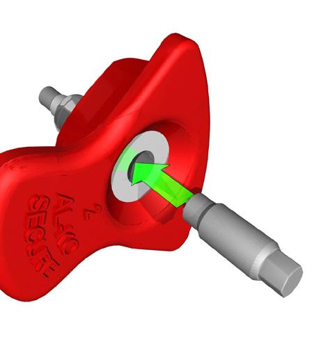
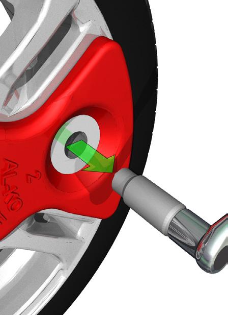
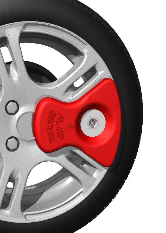
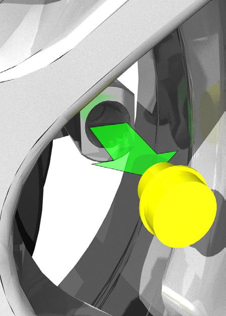
40 ACCESSORIES AL-KO SECURE AL-KO Secure is the Sold Secure Diamond Standard Wheel Lock for caravans with alloy wheels. Years of research and development have been undertaken to ensure that AL-KO Secure can withstand the maximum number of attack methods, and even deter thieves from approaching your caravan in the first place. Most caravans have the AL-KO Receiver fitted to the wheel drum as standard and some manufacturers include the wheel lock kit with the caravan at the time of purchase. To increase the security provided by the wheel lock, the lozenge is designed specifically to suit the alloy aperture and is therefore wheel rim specific. For more information about the AL-KO Secure Wheel Lock and to identify which wheel lock kit you need for your caravan, please visit our website at FITTING AL-KO SECURE 1. We recommend the use of a Side Lift Jack for easier fitting and removal of AL-KO Secure. Lift the caravan slightly to allow the wheel to rotate freely. Align the wheel so that the receiver can be seen in the centre of the rim opening. Do not use the rim opening in which the tyre valve is fitted. 2. Unscrew the Plastic Cap from the receiver and store in the Lock Kit Box. (When AL-KO Secure is not in use, always screw the Plastic Cap in place). 3. Insert the Locking Bolt into the Rim Specific Insert. 4. Insert the Locking Bolt Socket Key. 5. Line up the Locking Bolts and assembly with the receiver. 6. HAND TIGHTEN the Locking Wheel Bolt using the Wheel Spanner provided as shown, or a Torque Wrench. 7. Remove the Locking Bolt Socket Key. 8. Insert Barrel Lock. 9. Push the key fully into the lock and turn to operate the lock and then remove the key. 10. The AL-KO Secure is now fitted. 40


41 ACCESSORIES Fig 43 Fitting AL-KO Secure Wheel Lock 41
.")
.")
42 ACCESSORIES CORNER STEADIES Corner Steadies are as stated, for the purpose of steadying the caravan corners. They are NOT JACKS AND SHOULD NEVER BE USED AS SUCH. The screw and pivot pins should be lubricated periodically to ensure their satisfactory operation. (See also Jack Operation). SHOCK ABSORBERS All AL-KO chassis have pre-punched holes to accommodate Shock Absorbers, in front of the axle. On the Euro-Axle System, axle swing arms have a removable rectangular plastic cap exposing a slot to accommodate retro-fit brackets for the Octagon Shock Absorbers. (See Accessory Price List). Delta Axles have Shock Absorbers fitted as standard which MUST NOT BE REMOVED. STABILISERS AL-KO overruns can be fitted with a range of AL-KO Stabiliser devices (if not already fitted as standard), dependent on the maximum gross weight of the caravan. AL-KO stabilisers operate on a friction type basis, whereby friction pads grip onto a Dry, Grease Free Towball. It is important to note that the AKS range of stabilisers are suitable for use with swan neck, fixed or detachable type towbars or the special AL-KO Extended Neck Bolt-On Towball. We do not approve the use of any other bolt-on type towball, other than the AL-KO Towball. Failure to use the correct towball may result in product failure and will invalid your warranty. The AKS range is available in two different models, the AKS 1300 suitable for caravans with a maximum gross weight of 1360 Kg and the AKS 3004 which is suitable for caravans with a maximum gross weight up to 3000 Kg. Each Stabiliser can also be retro-fitted with an AL-KO Security Device and Safety ball, to ensure maximum theft deterrent (please see our accessory price list for further details). All Red coloured AL-KO Security Devices have full TUV and Sold Secure Approvals and are available from good dealers or direct at 42
43 ACCESSORIES ROAD WHEELS In most instances the road wheels and tyres are supplied by the Caravan Manufacturer. The condition of wheels and tyres should be checked regularly, particularly for distortion of flanges and the wheel dish. Wheels that are damaged or distorted, or have wheel bolt seatings cracked or deformed must not be repaired or used in service - these must be replaced. IMPORTANT NOTE Standard AL-KO caravan chassis use M12 bolts. These must always only be tightened to the correct torque setting as recommended by the vehicle manufacturer. They should be tightened in sequence, North, South, East, West and never clock or anti-clockwise. Always use a calibrated torque wrench and do not use a corner steady brace or power or electric wrench. It is as dangerous to overtighten wheel bolts as it is to not tighten them sufficiently. IMPORTANT NOTE The torque settings should be re-checked after 50 km. If other wheel bolts are used please ensure the torque settings are as follows: M10-49 Nm (36 ft. lb) M Nm (99.5 ft. lb) M Nm (155 ft. lb) SPECIAL NOTE - ALUMINIUM WHEELS The standard M12 x o Conical Wheel bolts are NOT SUITABLE for aluminium wheel rims. Special wheel bolts should be used. TYRES The legal requirements for tread depth on motor vehicles, also applies to caravan and trailers. 43


44 ACCESSORIES JACKS The Corner Steadies should never be used to jack up the caravan. When jacking becomes necessary use the AL-KO Side Lift Jack or 2-Tonne Jack system. NOTE It is essential that the car and caravan are hitched together before commencing jacking. All AL-KO chassis from 1992 onwards have 2 holes punched in the chassis members, each side (rear of the axle); to accept the brackets for the Jack(s). (See Accessory Price List). Corner Steadies may be used for stability ONLY, when the caravan is in the jacked position. The caravan should never be lifted by jacking up under the chassis member. If working under the caravan in an elevated position, axle stands must be used for safety. Wheel chocks for the opposite wheel(s) are also advisable. JOCKEY WHEEL All AL-KO Jockey Wheels are removable and stow neatly on the A-Frame when the caravan is being towed. AL-KO Jockey Wheels are hot dipped galvanised preventing corrosion and ensuring durability. They incorporate a thrust bearing which greatly reduces the effort required to manoeuvre the caravan. MAINTENANCE Lubricate screw thread and wheel spindle periodically. THE PREMIUM JOCKEY WHEEL The Premium Jockey Wheel is designed for use with motorised caravan movers and features extra wide, grooved rubber tyres, swing arm suspension and an integrated load indicator to gauge the noseweight of the caravan. This saves time and effort preparing for your journey. For more information about any of the AL-KO Jockey Wheels, please visit our website at 44


45 ACCESSORIES SPARE WHEEL CARRIERS Each caravan has a set of punched holes in the chassis member to facilitate the fitting of a spare wheel carrier. The assembly is of a strong, lightweight construction and zinc plated for all-weather protection. There are 3 variants to suit most AL-KO chassis (record your tyre size on this booklet for future reference). The carriers can be fitted for left or right hand operation and are easy to fit. The telescopic frame tubes should be lubricated periodically. RECORD YOUR SPARE WHEEL CARRIER INFORMATION HERE Caravan Make Caravan Model Year of Manufacture Tyre Size (eg R195 13) Dimension (X) in mm (taken from the following diagram) ca X Hole Cluster for Spare Wheel Carrier 45
46 TROUBLE SHOOTING & FAULT FINDING TABLE 1 AXLES FAULT CAUSE REMEDY POOR BRAKING DIFFICULTY IN REVERSING BRAKES OVERHEATING HANDBRAKE FORCE LOW UNCOMFORTABLE RIDE OR UNEVEN BRAKING Linings worn or damaged. Brake Linings not bedded in. Brake set up incorrect. Braking system set too tightly. Auto-Reverse lever too stiff. Incorrect setting. Braking system not fully released. Overrun lever stuck. Damage or Corrosion to braking system. Incorrect setting of the brakes. Linings not bedded in. Loose braking adjustment. Damper defective. Axle shock absorbers defective. Replace Brake Linings. Will pass after braking a few times. Reset Brakes as pages & ensure system is lubricated. Reset Brakes as page pages Lubricate and free off Reverse Lever. Reset Brakes as pages Check Handbrake has been released & the system is running freely. Lubricate and free off Reverse Lever. Check system as pages and repair or renew parts as necessary. Reset brakes as pages and lubricate as necessary. Will pass after braking a few times. Reset brakes as pages Check and replace damper if necessary. Replace shock absorber. 46
47 TROUBLE SHOOTING & FAULT FINDING TABLE 2 COUPLING HEADS FAULT CAUSE REMEDY COUPLING DOES NOT ENGAGE ONTO BALL Ball diameter too large. Ball could be damaged or deformed. Coupling head dirty or defective. Change ball to correct size. Fit new ball. Clean & Lubricate coupling and replace if necessary. DIFFICULTY IN UNCOUPLING BRAKES OVERHEATING TOO MUCH PLAY IN THE COUPLING Ball damaged or deformed. Coupling damaged or deformed. Coupling head under pressure from damper. Incorrect setting. Braking system not fully released. Overrun lever stuck. Damage or Corrosion to braking system. Coupling damaged or deformed. Ball too small. Fit new ball. Replace if necessary. Pull forward a few inches to relieve pressure. Reset Brakes as pages Check Handbrake has been released & the system is running freely. Lubricate and free off Reverse Lever. Check system as pages and repair or renew parts as necessary. Replace if necessary. Fit new ball. 47
48 TROUBLE SHOOTING & FAULT FINDING TABLE 3 OVERRUN DEVICES FAULT CAUSE REMEDY POOR BRAKING Overrun shaft tight. Overrun shaft corroded. Body housing damaged. Lubricate overrun shaft and replace any damaged parts. BRAKES OVERHEATING DURING TOWING HANDBRAKE FORCE LOW Handbrake not fully released. Braking system incorrectly set. Incorrect attachment of breakaway cable. Defective gas strut. Incorrect setting of spring cylinder. Release handbrake. Reset brakes as pages Ensure correct attachment as listed on pages 32/33 or refer to Braked Trailers Use of Breakaway Cables sheet. Replace gas strut. Reset spring cylinder as pages BRAKES APPLY DURING DECELERATION OR DOWNHILL TRAVEL Overrun damper is defective. Replace the overrun damper. 48
EC 94/20. Fig. 2 Fig. 3 Fig. 4
 ASSEMBLY AND OPERATING INSTRUCTIONS FOR AL-KO AKS 3004 STABILISER PLEASE ENSURE YOU READ THESE INSTRUCTIONS CAREFULLY, BEFORE COMMENCING ASSEMBLY OR OPERATION. REGULATIONS: 1) The AKS 3004 must be used
CARAVAN CHASSIS HANDBOOK FOR VEHICLES ON THE AL-KO CARAVAN CHASSIS
 CARAVAN CHASSIS HANDBOOK FOR VEHICLES ON THE AL-KO CARAVAN CHASSIS AL-KO CARAVAN CHASSIS GENERAL INFORMATION The AL-KO lightweight chassis has been perfected by many years of research and development,
3 Axles and brakes. 3.1 Function and construction of the axles Construction Function
 3 Axles and brakes 3.1 Function and construction of the axles 3.1.1 Function Each wheel has an independent suspension system in the axle body (1), so that individual wheel suspension is provided. The swinging
Workshop Manual. Chapter 1 Towball couplings
 Workshop Manual Chapter 1 Towball couplings Workshop Manual Chapter 2 Overrun Devices Workshop Manual Chapter 3 Axles and Brakes Workshop Manual Chapter 4 Height Adjustable Overrun Devices and Hitches
WAP disc brake technology. Assembly, operating and maintenance instructions
 WAP disc brake technology Assembly, operating and maintenance instructions Number MA-025 Date 22.07.2010 1 Please read this operating and service manual before starting the vehicle. It forms part of the
AL-KO SIDE LIFT JACK HANDBOOK FOR THE 1000KG SIDE LIFT JACK FOR CARAVANS WITH A MAXIMUM GROSS WEIGHT OF 2000KG
 AL-KO SIDE LIFT JACK HANDBOOK FOR THE 1000KG SIDE LIFT JACK FOR CARAVANS WITH A MAXIMUM GROSS WEIGHT OF 2000KG CONTENTS 3 WARNINGS & TECHNICAL INFORMATION 4 FITMENT OF JACK BRACKETS 7 OPERATING INSTRUCTIONS
AL-KO SIDE LIFT JACK HANDBOOK FOR THE 800KG SIDE LIFT JACK FOR CARAVANS WITH A MAXIMUM GROSS WEIGHT OF 1600KG
 AL-KO SIDE LIFT JACK HANDBOOK FOR THE 800KG SIDE LIFT JACK FOR CARAVANS WITH A MAXIMUM GROSS WEIGHT OF 1600KG CONTENTS 3 WARNINGS & TECHNICAL INFORMATION 4 FITMENT OF JACK BRACKETS 7 OPERATING INSTRUCTIONS
USER S HAND BOOK Braked Trailers & Chassis
 Issue 9 USER S HAND BOOK Braked Trailers & Chassis SERVICE SCHEDULE TASK BEFORE EACH JOURNEY Check the trailer visually for damage SEE SECTION Check connection to towing vehicle 1.4 Check tyre pressures
Shock Absorber OCTAGON SHOCK ABSORBERS IMPROVED RIDE COMFORT & ROADHOLDING QUALITY FOR LIFE
 Shock Absorber OCTAGON SHOCK ABSORBERS IMPROVED RIDE COMFORT & ROADHOLDING QUALITY FOR LIFE AL-KO OCTAGON SHOCK ABSORBERS IMPROVED RIDE COMFORT & ROADHOLDING MANUFACTURED BY INDUSTRY LEADERS AL-KO, AND
JSK 34. Installation and operating instructions
 JSK 34 EN Installation and operating instructions Table of contents 1 Explanation of symbols... 3 2 Safety information... 4 2.1 Safety information for operation... 4 2.2 Safety information for installation...
20 TONNE HYDRAULIC PRESS MODEL NO: CSA20FBT
 20 TONNE HYDRAULIC PRESS MODEL NO: CSA20FBT PART NO: 7614058 OPERATION & MAINTENANCE INSTRUCTIONS WARNING: Read these instructions before using the press GC0516 INTRODUCTION Thank you for purchasing this
SECTION 11 INTERMODAL EQUIPMENT
 SECTION 11 INTERMODAL EQUIPMENT ROA MANUAL SCHEDULE OF AMENDMENTS SECTION 11 AMENDMENT NUMBER PAGES AMENDED AMENDMENT SUMMARY DATE ISSUED TABLE OF CONTENTS Section Description Page No. 11.1 SCOPE... 11-1
INSTALLATION INSTRUCTIONS
 INSTALLATION INSTRUCTIONS WARNING: NEVER EXCEED YOUR VEHICLE MANUFACTURER'S RECOMMENDED TOWING CAPACITY A20 5TH WHEEL HITCH TABLE OF CONTENTS Page# Description 1 Warnings & Precautions 2 - Assembly & Installation
Sisu S-Cam Drum Brakes
 Sisu S-Cam Drum Brakes (For hub reduction rear axles since 1992) Maintenance Manual Sisu Axles, Inc. Autotehtaantie 1 P.O. Box 189 FIN-13101 Hämeenlinna Finland Phone int + 358 204 55 2999 Fax int + 358
the adaptable PrOFi V Cast OVErruN device introductory offer! Trailer ComponenTs QualiTy for life
 Trailer ComponenTs QualiTy for life the adaptable PrOFi V Cast OVErruN device WOrld leading OVErruN technology FOr demanding trailer applications limited introductory offer! 3 Tonne Assembly 100 3.5 Tonne
MAINTENANCE WEIGHT RATINGS WARNINGS. warning: never exceed your vehicle manufacturer's recommended towing capacity
 Installation instructions warning: never exceed your vehicle manufacturer's recommended towing capacity Round Bar WEIGHT DISTRIBUTION kit MAINTENANCE Keep the socket-mounted ends of the spring bars and
INSTALLATION INSTRUCTIONS
 INSTALLATION INSTRUCTIONS WARNING: NEVER EXCEED YOUR VEHICLE MANUFACTURER'S RECOMMENDED TOWING CAPACITY PIN-STYLE TRUNNION BAR WEIGHT DISTRIBUTION KIT MAINTENANCE Keep the socket-mounted ends of the spring
HYDRAULIC PALLET TRUCKS
 HYDRAULIC PALLET TRUCKS HYDRAULIC PALLET TRUCKS MODEL Nos: PT550 GAL & PT685 GAL PART Nos: 7630234 & 7630236 OPERATION & MAINTENANCE INSTRUCTIONS 0204 Please read these instructions carefully before operating
Brake Upgrade Kit Fitting Instructions Bonneville America
 WARNING: Always have Triumph approved parts, accessories and conversions fitted by a trained technician of an authorised Triumph Dealer. The fitment of parts, accessories and conversions by a technician
Towing TOWING A TRAILER. Trailer socket
 Towing TOWING A TRAILER E90953 WARNINGS Never exceed the maximum weights for either the vehicle or trailer. Doing so can cause accelerated wear and damage to the vehicle. It can also adversely affect vehicle
Accessory Fitting Instructions
 Accessory Fitting Instructions Kit Number Models Affected A9689 Thruxton 00 A96808 Thruxton 00 R Low Handlebar Kit Front Fairing Kit Kit Number Models Affected A97080 Thruxton 00 A97084 Thruxton 00 R Note:
HYDRAULIC PALLET TRUCK. MODEL No: PTE550 PART Nos OPERATION & MAINTENANCE INSTRUCTIONS
 HYDRAULIC PALLET TRUCK MODEL No: PTE550 PART Nos 7630171 OPERATION & MAINTENANCE INSTRUCTIONS 0604 Please read these instructions carefully before operating the truck Thank you for purchasing this CLARKE
2.- HANDLING OF VALVES BEFORE ASSEMBLY 3.- FITTING THE VALVE TO THE REST OF THE ASSEMBLY 5.- PERIODICAL INSPECTION OF THE VALVE AND MAINTENANCE
 Page 1 of 16 CONTENTS 1.- INTRODUCTION 2.- HANDLING OF VALVES BEFORE ASSEMBLY 3.- FITTING THE VALVE TO THE REST OF THE ASSEMBLY 4.- OPERATION OF A BALL VALVE 5.- PERIODICAL INSPECTION OF THE VALVE AND
disc brake axle with WABCO calipers
 1 2 disc brake axle with WABCO calipers 3 4 disc brake axle with WABCO calipers 5 6 disc brake axle with WABCO calipers IMT axles are supplied as non-cambered and are within the limits of a 2 minute negative
BPW height-adjustable drawbars
 Maintenance instructions ZAV BPW BERGISCHE ACHSEN BPW height-adjustable drawbars Series ZAV REPAIR, MAINTENANCE AND OPERATING INSTRUCTIONS Maintenance and Operating Instructions ZAV Table of contents:
Repair manual for. JSK 26 D fifth wheel coupling
 Repair manual for JSK 26 D fifth wheel coupling ZDE 199 7 17 6/213 1 Foreword Table of contents Page Fifth wheel couplings are vehicle-connecting parts that must comply with very high safety requirements
 AUTOGARD SERIES 820 TORQUE LIMITER Installation and Maintenance Manual DB0009 Issue 11 21 Feb 2017 British Autogard Ltd 2 Wilkinson Rd., Love Lane Industrial Estate, Cirencester, Glos., GL7 1YT UK Tel.
MAINTENANCE MAINTENANCE
 Vehicle modification and non-standard parts... 208 Caravan movers... 208 Caravan exterior... 208 Condensation... 209 Caravan interior... 210 Winterisation/storage... 212 AL-KO chassis... 215 AL-KO ATC
TO BE COMPLETED BY DEALER
 TO BE COMPLETED BY DEALER Trailer Model Serial Number Date Of Manufacture Date Of Sale 1 CONTENTS General Information 1 1.1 You and your towing vehicle 1 1.2 Your trailer 1 1.2.1 Specification and loading
FRONT SUSPENSION GROUP 2 FRONT SUSPENSION 2-1 CONTENTS SPECIFICATIONS VC-1, VC-2, VC-3 VY-1 TOOL LIST. Page
 GROUP 2 FRONT SUSPENSION CONTENTS Page Specifications 1 Tool List.... 1 Torque Reference 2 Preparation for Measuring Front End Alignment... 2 Front Suspension Height Adjustment 3 Front Suspension Alignment
SECTION H STEERING. Section Description Page No. H.1 GENERAL DESCRIPTION 3 H.2 STEERING WHEEL 3 H.3 INNER COLUMN 5 H.
 SECTION H STEERING Section Description Page No. H.1 GENERAL DESCRIPTION 3 H.2 STEERING WHEEL 3 H.3 INNER COLUMN 5 H.4 OUTER COLUMN 5 H.5 STEERING UNIT LOCK STOPS 6 H.6 STEERING UNIT 6 H.7 STEERING ARMS
SECTION G HUBS, WHEELS AND TYRES. Section Description Page G.1 GENERAL DESCRIPTION 3 G.2 FRONT HUBS 3 G.3 FRONT HUBS - REMOVE AND REPLACE 4
 SECTION G HUBS, WHEELS AND TYRES Section Description Page G.1 GENERAL DESCRIPTION 3 G.2 FRONT HUBS 3 G.3 FRONT HUBS - REMOVE AND REPLACE 4 G.4 REAR HUBS - REMOVE AND REPLACE 5 G.5 WHEELS 6 G.6 TYRES 6
Finishing Mower Estate 72
 Finishing Mower Estate 72 Owners/Operators Manual & Spare Parts List Issue Date: October 2011 1 Introduction Your FIELDMASTER Estate 72 Finishing Mower has been designed to do a range of work to your satisfaction.
1989 Jeep Cherokee. STEERING COLUMN' '1989 STEERING Jeep Steering Columns STEERING COLUMN STEERING Jeep Steering Columns
 STEERING COLUMN 1989 STEERING Jeep Steering Columns DESCRIPTION All models use collapsible steering columns. All columns have integral ignition switch and locking device. Optional tilt wheel is available
OPERATIONS MANUAL LEVER CHAIN HOIST
 OPERATIONS MANUAL LEVER CHAIN HOIST IMPORTANT SAFETY INFORMATION Please read, understand and follow all safety information contained in these instructions prior to the use of this hoist. Retain these instructions
REMOTE CARAVAN MOVER Installation guide and user information. e-go /10/01/rev 3
 REMOTE CARAVAN MOVER Installation guide and user information Contents 1 1 Introduction 3 Parts List 4 Safety Guidelines 4 Technical Specifications 5 Fitting Guidelines (chassis adapters etc.) 6 Fitting
MAINTENANCE WEIGHT RATINGS WARNINGS. warning: never exceed your vehicle manufacturer's recommended towing capacity
 Installation instructions warning: never exceed your vehicle manufacturer's recommended towing capacity Round Bar WEIGHT DISTRIBUTION MAINTENANCE Keep the socket-mounted ends of the spring bars and the
Maintenance and Repair Instructions TM 89/03
 TM 89/0 410 X 180 Simplex 410 X 180 Duplex 500 X 10 Simplex 500 X 160 Simplex 500 X 180 Duplex The brake described in this manual is subject to development and corresponds to the state-of-the-art at the
Instruction Manual Montage- und Betriebsanleitung Notice d utilisation
 Instruction Manual Montage- und Betriebsanleitung Notice d utilisation 2 Cast Fifth Wheel 2 Guss-Sattelkupplung Sellette 2 en fonte C O N N E C T Y O U R B U S I N E S S W I T H F O N T A I N E C O N T
BRAKE SYSTEM Return To Main Table of Contents
 BRAKE SYSTEM Return To Main Table of Contents GENERAL... 2 BRAKE PEDAL... 10 MASTER CYLINDER... 13 BRAKE BOOSTER... 16 BRAKE LINE... 18 PROPORTIONING VALVE... 19 FRONT DISC BRAKE... 20 REAR DRUM BRAKE...
MailStar Maintenance and Adjustment March 2002
 MailStar Maintenance and Adjustment March 2002 The MailStar bicycle incorporates many new features to ease maintenance and improve handling and performance. The majority of components are similar to those
PACKING, HANDLING, TRANSPORTING AND STORING MOTORS
 PACKING, HANDLING, TRANSPORTING AND STORING MOTORS Make sure that the shaft of the motor is not loaded in any way and is protected from knocks. Axial loads or shocks may easily damage the bearings inside
INDEX Page GENERAL INSTRUCTIONS 2
 INDEX Page GENERAL INSTRUCTIONS 2 ASSEMBLY OF HUBS FITTED WITH TAPER ROLLER BEARINGS Preparation 2 Fitting 3 Adjustment 3 BRAKES Axles fitted with Girling brakes 4 Axles fitted with Lockheed brakes 4 Brake
English. Fitting Instructions: Thunderbird Commander A of 9
 English Fitting Instructions: Thunderbird Commander A95806 Thank you for choosing this Triumph genuine accessory kit. This accessory kit is the product of Triumph's use of proven engineering, exhaustive
SCdefault. 900 Installation instructions
 SCdefault 900 Installation instructions SITdefault Sports chassis MONTERINGSANVISNING INSTALLATION INSTRUCTIONS MONTAGEANLEITUNG INSTRUCTIONS DE MONTAGE Accessories Part No. Group Date Instruction Part
Accessory Fitting Instructions
 Accessory Fitting Instructions Expedition Aluminium Pannier Kit - Silver Kit Number A9500600 A9500800 Models Affected Tiger XR, Tiger XRT, Tiger XRX, Tiger XC, Tiger XCA, Tiger XCX, Tiger Explorer XR,
Auxiliary Air Suspension. Installation Manual L.AL.02. AL-KO Chassis June 2009
 Auxiliary Air Suspension Installation Manual AL-KO Chassis 2002 2006 June 2009 CONTENTS 1. FOREWORD... 3 2. VERY IMPORTANT PREREQUISITES... 4 3. INTRODUCTION... 5 4. VERY IMPORTANT NOTES... 5 5. CONTENTS
English. Fitting Instructions: Bonneville and Bonneville T100 A , A and A of 9. Parts Supplied:
 English Fitting Instructions: Bonneville and Bonneville T00 A958085, A958086 and A958087 Thank you for choosing this Triumph genuine accessory kit. This accessory kit is the product of Triumph's use of
Mechanical Disc Brake
 (English) DM-BR0007-02 Dealer's Manual Mechanical Disc Brake BR-CX77 BR-CX75 BR-R517 BR-R515 BR-R317 BR-R315 BR-TX805 IMPORTANT NOTICE This dealer s manual is intended primarily for use by professional
Model Number: CM-046. QUATTRO Handset Installation guide and user information. Ref: CM-046 UK-Rev.C.
 Model Number: CM-046 QUATTRO Handset Installation guide and user information UK Ref: CM-046 UK-Rev.C. Table of Contents Package Contents (Parts List) Page 2 Introduction Page 4 Installation Safety Guidelines
SECTION ZF FRONT AXLE
 04-101.01/ 1 2011JA14 SECTION 04-101.01 6 3 5 1 2 9 1. Upper radius rod 2. Lower radius rod 3. Caliper 4. BRAKE Disk 5. Pneumatic connector 6. Hub 7. steering knuckle 8. Grease Fitting 9. Pneumatic connector
W BW GW. Workshop manual. Mechanical suspensions BPW, series ECO Cargo W / BW / GW. BPW-WH-W-BW-GW e
 W BW GW Workshop manual Mechanical suspensions BPW, series ECO Cargo W / BW / GW BPW-WH-W-BW-GW 35251401e Page 2 BPW-WH-W-BW-GW 35251401e BPW-WH-W-BW-GW 35251401e Page 3 Contents 1. Product identification...
Installation instructions
 Installation instructions warning: never exceed your vehicle manufacturer's recommended towing capacity BOLT-TOGETHER WEIGHT DISTRIBUTION MAINTENANCE Keep the socket-mounted ends of the spring bars and
LC I LIPPERT COMPONENTS DISC BRAKE SYSTEM FOR TRAILERS INSTALLATION, OPERATION & SERVICE MANUAL. Table of Contents
 LC I LIPPERT COMPONENTS DISC BRAKE SYSTEM FOR TRAILERS INSTALLATION, OPERATION & SERVICE MANUAL Table of Contents Introduction... 2 Safety Information... 2 Installation... 3 Solenoid Reversing Valves...
1. General Description
 General Description 1. General Description A: SPECIFICATION Front Rear Model Wheel arch height (Tolerance: +12 mm 24 mm ( +0.47 in 0.94 in)) mm (in) 376 (14.8) Camber (Tolerance: 0 45 Differences between
SECTION C FRONT SUSPENSION. Section Description Page C.1 REMOVING AND REFITTING A FRONT SUSPENSION UNIT 5
 SECTION C FRONT SUSPENSION Section Description Page C.1 REMOVING AND REFITTING A FRONT SUSPENSION UNIT 5 C.2 REMOVING AND REFITTING THE COMPONENTS OF THE FRONT SUSPENSION 8 C.3 CHECKING AND OVERHAULING
TROUBLESHOOTING SPECIAL TOOL ASSEMBLY AND ADJUSTMENT
 1 INDEX Models FD, FE, FF and SG REAR AXLE 10-1 10-108E-07 CHAPTER 10 REAR AXLE Models FD, FE, FF and SG TROUBLESHOOTING...10-2 10 SPECIAL TOOL...10-3 WHEEL HUB AND RELATED PARTS DISASSEMBLY...10-7 INSPECTION...10-9
Rating when used as a weight distributing hitch with spring bars:
 May 2004 APPLICATION: INSTALLATION INSTRUCTIONS MODEL NO. 70201 Bolt Together Weight Distributing Hitch System Without Shank Rating when used as a weight distributing hitch with spring bars: Part Number
HEAVY DUTY TROLLEY JACK. Operation Manual
 HEAVY DUTY TROLLEY JACK 4T Operation Manual Make sure to read and fully understand the instruction manual before using this product and keep the manual properly 1 General Description Product Description
HYDRAULIC PALLET TRUCK
 HYDRAULIC PALLET TRUCK Models; PT550C & PT685C Part Nos 7630172 & 7630177 OPERATING & MAINTENANCE INSTRUCTIONS GC05/12 INTRODUCTION Thank you for purchasing this CLARKE Pallet Truck. Before attempting
Installation Instructions READ THOROUGHLY BEFORE BEGINNING Signature Series Rail Kit Dodge Ram Trucks-all, including Mega-cabs
 INDEX Failure to follow all of these instructions may result in death or serious injury!. GUIDELINES FOR MATCHING TOW VEHICLE AND TRAILER. Pages -. DRILLED AND BOLTED INSTALLATION FIGURE. Page 4. NO-DRILL,
This file is available for free download at
 This file is available for free download at http://www.iluvmyrx7.com This file is fully text-searchable select Edit and Find and type in what you re looking for. This file is intended more for online viewing
PAN 17 MECHANICAL SLIDING CALLIPER DISC BRAKE ASSEMBLY AND MAINTENANCE INSTRUCTIONS
 PAN 17 MECHANICAL SLIDING CALLIPER DISC BRAKE ASSEMBLY AND MAINTENANCE INSTRUCTIONS PAN 17 MECHANICAL SLIDING CALLIPER DISC BRAKE Assembly and Maintenance Instructions 2nd edition This publication is
Rating when used as a weight distributing hitch with spring bars:
 January 2007 INSTALLATION INSTRUCTIONS 70210 70220 70230 Bolt Together Weight Distributing Hitch System Rating when used as a weight distributing hitch with spring bars: Part Number Max. Tongue Wt. Max
Maintenance. maintenance
 maintenance Vehicle modification and non-standard parts... 178 Caravan movers... 178 Caravan exterior... 178 Caravan interior... 180 Winterisation/storage... 184 AL-KO chassis... 187 AL-KO ATC control
50 TONNE HYDRAULIC PRESS MODEL NO: CSA50FP
 50 TONNE HYDRAULIC PRESS MODEL NO: CSA50FP PART NO: 7615202 OPERATION & MAINTENANCE INSTRUCTIONS WARNING: Read these instructions before using the press GC0516 INTRODUCTION Thank you for purchasing this
Q5 5 th Wheel. Unpacking Assembly / Installation
 PA1 Unpacking Assembly / Installation Installer: Read and understand this manual. Fully instruct and demonstrate the operation of this 5 th Wheel Hitch to the End-User. Include the importance of observing
HYDRAULIC PALLET TRUCK MODEL NO: PT540M/BM/CM & PT685BM/CM PART NO: , , , ,
 HYDRAULIC PALLET TRUCK MODEL NO: PT540M/BM/CM & PT685BM/CM PART NO: 7631700, 7631705, 7631710, 7631715, 7631720 OPERATION & MAINTENANCE INSTRUCTIONS LS0316 INTRODUCTION Thank you for purchasing this CLARKE
Maintenance instructions. BPW Trailer Axles and Suspensions. BPW-W e
 Maintenance instructions BPW Trailer Axles and Suspensions BPW-W 33111701e Page 2 BPW-W 33111701e BPW-W 33111701e Page 3 Contents Important information 1 1. Important information... Page 3 1.1 General
English. Fitting Instructions: Tiger 800 A of 7. Parts Supplied:
 English Fitting Instructions: Tiger 800 A9708 Thank you for choosing this Triumph genuine accessory kit. This accessory kit is the product of Triumph's use of proven engineering, exhaustive testing, and
English. Fitting Instructions: Tiger 800 A of 7. Parts Supplied:
 English Fitting Instructions: Tiger 800 A9708 Thank you for choosing this Triumph genuine accessory kit. This accessory kit is the product of Triumph's use of proven engineering, exhaustive testing, and
1988 Chevrolet Pickup V SUSPENSION - FRONT (4WD)' 'Front Suspension - "V" Series 1988 SUSPENSION - FRONT (4WD) Front Suspension - "V" Series
' 'Front Suspension - V Series 1988 SUSPENSION - FRONT (4WD) Front Suspension - V Series") 1988 SUSPENSION - FRONT (4WD) Front Suspension - "V" Series DESCRIPTION NOTE: Vehicle serial numbers used in this article has been abbreviated for common reference to Chevrolet and GMC models. Chevrolet
1988 SUSPENSION - FRONT (4WD) Front Suspension - "V" Series DESCRIPTION NOTE: Vehicle serial numbers used in this article has been abbreviated for common reference to Chevrolet and GMC models. Chevrolet
Vision Ped Plus. Operators Guide. Studio Pedestal. Vinten Camera Control Solutions
 Operators Guide Vision Ped Plus Studio Pedestal Vinten Camera Control Solutions Vision Ped Plus Studio Pedestal Publication Part No. 3951-8 Issue 1 Copyright Vinten Broadcast Limited 2002 All rights reserved
SECTION D REAR SUSPENSION. Section Description Page D.1. REMOVING AND REFITTING A REAR SUSPENSION UNIT 5
 SECTION D REAR SUSPENSION Section Description Page D.1. REMOVING AND REFITTING A REAR SUSPENSION UNIT 5 D.2. REMOVING AND REFITTING THE COMPONENTS OF THE REAR SUSPENSION 8 D.3. CHECKING AND OVERHAULING
Service Instruction Front Suspension PASHLEY-MOULTON. 1.0 General Description. 2.0 Adjustment
 Service Instruction Front Suspension PASHLEY-MOULTON 1 General Description 2 Adjustment 3 Problems and their Remedies 3.1 Clunking or Banging Noises 3.2 Suspension Squeaking 3.3 Seized Suspension 4 Disassembly
2 TONNE GARAGE JACK Model No: CTJ2QLP PART NO:
 TONNE GARAGE JACK Model No: CTJQLP PART NO: 7680 OPERATING & MAINTENANCE INSTRUCTIONS GC03 INTRODUCTION Thank you for purchasing this CLARKE Garage Jack. Before attempting to use this product, please read
Installation Instructions
 Equipment Required: Wrenches: 9/16, 3/4, 1-1/8 Drill Bits: 11/32 Torque Wrench capable of reading 260 ft-lbs. Installation Instructions IN DEALERS: Please give these instructions to your customer. Do Not
Montage- und Betriebsanleitung Sattelkupplung JSK 26 D 5. Installation and operating instrutions for fifth wheel coupling JSK 26 D 17
 Montage- und Betriebsanleitung Sattelkupplung JSK 26 D 5 Deutsch Installation and operating instrutions for fifth wheel coupling JSK 26 D 7 Instructions de montage et de d utilisation pour sellette d attelage
BURQUIP INTERNATIONAL (PTY) LTD
 LTD") Chapter 6 Transmission The transmission system comprises all of the components that transfer the force and movement from the Braked Coupler to the inertia brakes in the axles. Fit the axles to the trailers
Chapter 6 Transmission The transmission system comprises all of the components that transfer the force and movement from the Braked Coupler to the inertia brakes in the axles. Fit the axles to the trailers
THE GLIDER 5th Wheel Attachment
 April 2007 APPLICATION: INSTALLATION INSTRUCTIONS MODEL NO. 70460 70046 THE GLIDER 5th Wheel Attachment For use on short bed pickup applications US Patent No. 6247720 COMPLETE PARTS LIST Part Description
Mechanical Disc Brakes
 (English) DM-BR0009-00 Dealer's Manual ROAD MTB Trekking City Touring/ Comfort Bike URBAN SPORT E-BIKE Mechanical Disc Brakes BR-CX77 BR-CX75 BR-R517 BR-R515 BR-R317 BR-R315 CONTENTS IMPORTANT NOTICE...
MAXX TM 22T MECHANICAL SLIDING CALIPER DISC BRAKE INSTALLATION AND MAINTENANCE INSTRUCTIONS
 MAXX TM 22T MECHANICAL SLIDING CALIPER DISC BRAKE INSTALLATION AND MAINTENANCE INSTRUCTIONS MAXX TM 22T Mechanical Sliding Caliper Disc Brake Installation and Maintenance Instructions Edition 1 This publication
Accessory Fitting Instructions
 Accessory Fitting Instructions Swinging Arm Bag Kit, Waxed Cotton, Olive Kit Number Models Affected A908 Bonneville Bobber, Bonneville Speedmaster from VIN 79 Swinging Arm Bag Kit, Waxed Cotton, Black
Chapter 10 Suspension and steering
 10 1 Chapter 10 Suspension and steering Contents Front hub bearings - renewal 3 Front swivel hub assembly - removal and refitting 2 Front suspension and steering check See Chapter 1 Front suspension anti-roll
Tooling Assistance Center
 Safeguards are designed into this application equipment to protect operators and maintenance personnel from most hazards during equipment operation. However, certain safety precautions must be taken by
<THESE INSTRUCTIONS MUST BE GIVEN TO THE END USER> B&W
 B&W Trailer Hitches 6 Hawaii Rd / PO Box 86 Humboldt, KS 66748 P:60.473664 F:60.869.903 Turnoverball Gooseneck Hitch Installation Instructions MODEL 08
Wheel Changing ! WARNING: Spare Wheel Location
 Spare Wheel Location Be prepared for a flat tyre. Know where equipment is stowed and read the wheel changing and jacking instructions carefully. Pull off the road completely, clear of all traffic and park
WARNING: Only perform this installation if you are experienced, fully equipped mechanic.
 DYNATRAC V3.2 2005-Present Ford Super Duty 250/350-4x4, Front Axle, Free Spin Conversion Kit Some of the less common tools, which will be required: 6 point Spanner socket (OTC #7090-A or equivalent). These
Mechanical Sliding Caliper Disc Brake. Type PAN 19-1 Assembly and Maintenance Instructions
 WABCO Mannheim Mechanical Sliding Caliper Disc Brake Type PAN 19-1 Assembly and Maintenance Instructions WABCO Radbremsen GmbH Postfach 71 02 63 D-68222 Mannheim Bärlochweg 25 D-68229 Mannheim +49 (0)6
ZE ZE ZE. Simplex expanding wedge brake Assembly and Maintenance Instructions
 Simplex expanding wedge brake Assembly and Maintenance Instructions Simplex expanding wedge brake Assembly and Maintenance Instructions Edition 1 This publication is not subject to any update service.
Rear axle, servicing (frontwheel-drive
 Page 1 of 26 42-1 Rear axle, servicing (frontwheel-drive vehicles) WARNING! Do not attempt to weld and/or straighten the axle beam. Do not re-use fasteners that are worn or deformed in normal use. Some
Maintenance Information
 80234313 Edition 1 June 2006 Air Grinder, Die Grinder, Sander and Belt Sander Series G1 (Angle) Maintenance Information Save These Instructions WARNING Always wear eye protection when operating or performing
Owners manual. Öhlins Superbike front fork FG 170
 Owners manual Öhlins Superbike front fork FG 0 Including: Setting up your fork Changing springs and seals Service the fork Trouble shooting Technical info Spare parts & tools Öhlins super bike front fork
2006 MINI Cooper SUSPENSION Wheels & Tires - Repair Instructions - Cooper (1.6L) R50/W10 & Cooper S
 R50/W10 & Cooper S") WHEELS 2002-05 SUSPENSION Wheels & Tires - Repair Instructions - Cooper (1.6L) R50/W10 & Cooper S 36 10 300 REMOVING OR INSTALLING FRONT OR REAR WHEEL NOTE: For Special Tool identification, see WHEEL AND
WHEELS 2002-05 SUSPENSION Wheels & Tires - Repair Instructions - Cooper (1.6L) R50/W10 & Cooper S 36 10 300 REMOVING OR INSTALLING FRONT OR REAR WHEEL NOTE: For Special Tool identification, see WHEEL AND
Maintenance Information
 Form 16575334 Edition 1 April 2005 Electric Screwdrivers EL, EP and ET 34V DC Series Maintenance Information Save These Instructions WARNING Maintenance procedures have the potential for severe shock hazard
 DRUM BRAKE RIMS Periodic inspection of drum brake rims is necessary to determine indications of uneven or excessive wear. In general, brake rim failures other that regular wear are caused by brake linings
INSTALLATION OF RAILGEAR KIT R-290HD REAR
 INSTALLATION OF RAILGEAR KIT R-290HD REAR Page 1 of 29 SAFETY PRECAUTIONS If any installation problems are encountered, please call G&B Specialties, Inc. for technical assistance before continuing with
SUSPENSION 2-1 SUSPENSION TABLE OF CONTENTS
 XJ SUSPENSION 2-1 SUSPENSION TABLE OF CONTENTS page ALIGNMENT... 1 FRONT SUSPENSION... 7 page REAR SUSPENSION... 16 ALIGNMENT TABLE OF CONTENTS page AND WHEEL ALIGNMENT...1 DIAGNOSIS AND TESTING SUSPENSION
Performance Brake Caliper Guide Bushing Set Installation Guide
 Performance Brake Caliper Guide Bushing Set Installation Guide Proper service and repair procedures are vital to the safe, reliable operation of all motor vehicles as well as the personal safety of those
DRIVE AXLE Volvo 960 DESCRIPTION & OPERATION AXLE IDENTIFICATION DRIVE AXLES Volvo Differentials & Axle Shafts
 DRIVE AXLE 1994 Volvo 960 1994 DRIVE AXLES Volvo Differentials & Axle Shafts 960 DESCRIPTION & OPERATION All 960 station wagon models use type 1041 rear axle assembly. All 960 4-door models use type 1045