INDEX Page GENERAL INSTRUCTIONS 2
|
|
|
- Elijah Adams
- 6 years ago
- Views:
Transcription
1
2
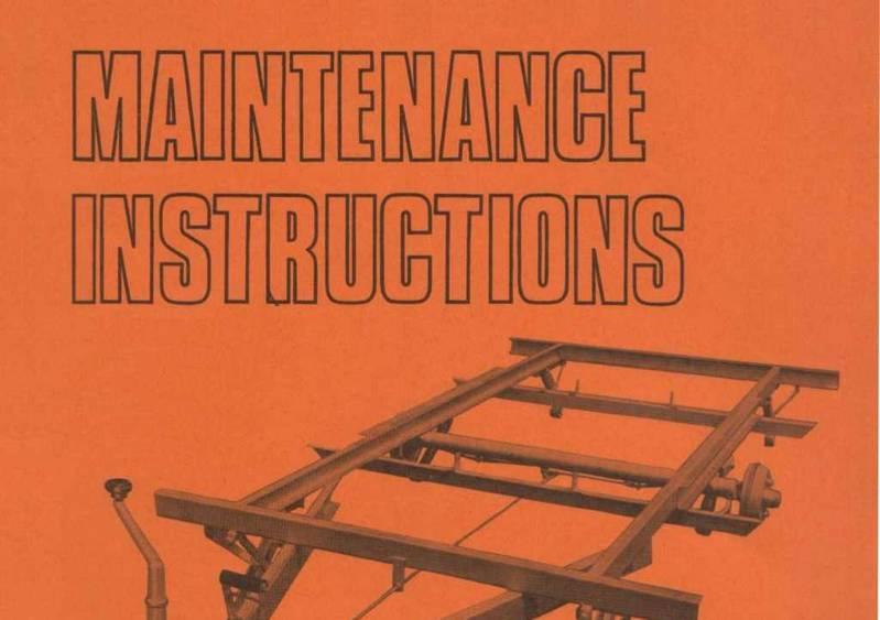
3 INDEX Page GENERAL INSTRUCTIONS 2 ASSEMBLY OF HUBS FITTED WITH TAPER ROLLER BEARINGS Preparation 2 Fitting 3 Adjustment 3 BRAKES Axles fitted with Girling brakes 4 Axles fitted with Lockheed brakes 4 Brake linings 4 TORSION BAR AXLES Replacement 5 Maintenance 5 Boat trailer axles 5 ELECTRIC BRAKE AXLES Initial adjustment 6 CHECKING THE ELECTRICAL CIRCUIT 6 CHECKING THE ELECTRICAL COMPONENTS 6 1. Automatic controller bench check 6 2. Stop light switch 7 3. Hydraulic cylinder leakage 7 4. Magnet assembly 7 5. Magnet bench check 8 CHECKING THE MECHANICAL COMPONENTS 1. Bearings and seals 8 2. Armature plates 8 3. Brake adjustment 8 BOAT TRAILER ELECTRIC BRAKES 9 SMOOTHA-HITCH 10 Electrically operated reversing mechanism 10 CHASSIS 10


 The interior of the hubs must be clean before liberally packing with good quality high melting point taper roller bearing grease i.e. Retinax A, Nulsec L or equivalent.")

4 GENERAL INSTRUCTIONS To ensure satisfactory operation of all working parts the following instructions should be carried out at intervals of 3,000 miles or prior to the trailer remaining stationary for periods exceeding six months unless otherwise stated. ASSEMBLY OF HUBS FITTED WITH TAPER ROLLER BEARINGS PREPARATION (a) The hub or the hub portion of a combined brake drum and hub will have the taper roller bearing cups securely and accurately in position. WHEELS Check tightness of wheel nuts. Check tyre pressures weekly and maintain the pressures at maker s recommendation. Any unusual pressure loss should be investigated as under-inflation causes rapid tyre wear and may damage the cords of the fabric. (b) The interior of the hubs must be clean before liberally packing with good quality high melting point taper roller bearing grease i.e. Retinax A, Nulsec L or equivalent. HUBS (c) The operating diameters of the axle must be clean. Remove hub cap. Check taper roller bearing adjustment by rocking hub. There should be little or no perceptible shake but should be complete freedom to rotate. (For lubrication of taper roller bearings see Assembly of hubs fitted with taper roller bearings ). (d) The taper roller bearing cones must be greased as (b) ensuring that the grease penetrates inside the roller cage, between the rollers and the cones, 2
 The slotted nut must then be tightened using a spanner.")


5 ADJUSTMENT FITTING (e) The inner bearing cone must be placed inside the inner bearing cup and the grease seal placed into position inside the hub. (g) The slotted nut must then be tightened using a spanner. (f) The hub subassembly must then be carefully positioned on the axle and supported squarely until the outer bearing cone has been placed in position inside its cup, the washer placed against it, and the slotted nut hand tightened against the washer. If this procedure is not adhered to the grease seal could be damaged. I IMPORTANT: Whilst this is being done the hub must be rotated by hand until it is locked by the tightening of the nut acuon then slacken off the slotted nut through 120 (i.e. two fiats I or until.003 to.007 end float is attained. Periodic checks must be made to ensure that the end float is maintained, NOTE! The hubs must not be struck with a mallet The selection of the appropriate slot to line up with the split pin hole must be made so that the end float is nearer to the.003 where possible. End float must never be less than.003 since too little will pre-load the bearings and result in premature failure. (h) The split pin must be inserted and the outside leg bent over as shown. The inside leg must be cut short. 3

 at the rear of each brake")


6 (j) The hub cap is placed into position and secured by tapping with a mallet. Correct setting of compensated brake linkage on torsion BRAKES Before attempting brake adjustment lift each wheel clear of the ground with a jack, and slacken off the hitch to brake linkage. AXLES FITTED WITH GIRLING BRAKES Adjustment is effected by rotating the adjusting screw (A) at the rear of each brake backplate in a clockwise direction until the shoes are in contact with the drums and preventing rotation of the hub; the screw is then rotated three clicks in an anti-clockwise direction or until free rotation of wheel is obtained; re-set main brake linkage. bar axles. Correct setting of compensated brake linkage on square Adjustment is effected by first removing the wheel, revealing AXLES FITTED WITH LOCKHEED BRAKES beam axles. BRAKE LININGS the plastic cap in the brake drum. Remove the cap and rotate the drum until the adjusting screw appears in the hole. Using a screwdriver, rotate screw until shoes contact drum and prevent rotation of hub. Rotate screw in opposite direction for three clicks, or until free rotation of the hub is obtained. Replace plastic cap and wheel. Re-set main brake linkage. Inspect the brake linings for wear, If a lining is worn to the rivets it should be replaced. If a lining is badly contaminated with grease, oil etc., it must be replaced, since contamination of this type cannot be sanded or dissolved out. IMPORTANT. Always replace brake linings in sets on both brakes on the same axle. 4


7 TORSION BAR AXLES REPLACEMENT To replace a torsion bar lift the side required with a jack. Remove swing arm cone screw and locknut. Remove bar from the swing arm sub-assembly. Taking care to place dimple for screw location in the torsion bar adjacent to screw hole, fit new torsion bar and replace locknut and screw, tightening both to torque of lb ft. Refit swing arm sub-assembly and replace locknut and screw, applying lb. ft. torque. Reconnect brake end fitting and adjust as necessary. Replace wheel. MAINTENANCE Remove swing arm sub-assembly on each side as outlined above. The following are necessary as an anti-corrosive measure. Grease torsion bar and ground sleeve attached to swing arm. The recommended lubricants for all applications are Retinax A, Nulsec L or equivalent. BOAT TRAILER AXLES Remove the wheel. Remove brake cable end fitting from abutments on underside of axle tube. On the required side and near the centre front, slacken Special attention should be given to boat trailer axles which are subjected to immersion during boat launchings To ensure the satisfactory operation of all working parts the following instructions should be carried out at intervals of six months or before trailer is stored. 1. Carry out normal torsion bar and square beam axle maintenance as previously stated 2. Remove wheels. Remove plastic and wash out brake drums with clean fresh water. Refit plastic caps and wheels. A short run after this operation using the brakes as much as possible will ensure thorough drying out for storage. 3.Remove hub caps. Inspect internal fittings for corrosion. Repack with grease if required. Replace hub cap. the locknut on the axle tube. Remove the cone screw and locknut. Remove swing arm sub-assembly and torsion bar by tapping with mallet the inside face of swing arm close to the tube. 4. SPECIAL NOTE FOR CONTINUED SUBMERSION IN SEA WATER. Where there has been submersion in the sea water for periods of more than one hour washing out of brakes after each submersion as outlined in (2) is essential for continued satisfactory operation. 5
8 ELECTRIC BRAKE AXLES INITIAL ADJUSTMENT For controllers fitted with hydraulic plunger adjustment. Before road use the controller lever should be turned to set the adjustment in the mean position. During initial road tests adjust the hydraulic plunger if necessary to give the optimum performance. Slight variations may be carried out by rotation of the controller ever during towing to suit requirements. CHECKING THE ELECTRICAL CIRCUIT TEST INSTRUMENT In order to check the electrical circuit and components, a D. C. ammeter should be used (0-15 amps for 2 to 4 brakes). However, in an emergency an automotive lamp may be used as a test bulb. Be sure to use an automotive test bulb of the same voltage (6 volt or 12 volt) as the trailer brakes. TESTING THE CIRCUIT First check the continuity of the system. To do this connect the trailer to the towing vehicle, then place the ammeter or test bulb in the circuit as shown in diagram. NOTE: Whenever connecting the ammeter, you can avoid possible damage to the ammeter by connecting one lead then just touching the other lead quickly. If the needle goes over the wrong way the polarity is reversed. To correct, simply reverse the leads, then complete the connection. Now operate the controller slowly. The cutin lowest current should read from 1 to 1Ö amp. The reading will vary, depending on the voltage and the number of brakes in the system. For 8 and 9 dia. 2 braked axles the amperage reading should be 5-6 for 12 volt towing systems. If the ammeter registers the correct high and low readings and shows smooth current modulation you may assume that the controller is functioning properly. If you do not show the correct high and low or the modulation is poor, check the following electrical circuit problems. If you are using a test light instead of an ammeter, the bulb should be out when the controller is off, burn dimly as controller application starts, and gradually burn more brightly as the controller handle is moved toward on. In full on position the bulb should burn with maximum brightness. CHECK WITHOUT TRAILER If trailer is not available a quick check of the towing vehicle circuit may be made by inserting the test bulb at the towing vehicle connector socket. Operate the controller slowly. If, as the controller handle is moved toward on the light goes from dim to bright or the ammeter shows a gradual rise, the towing vehicle circuit is probably alright. CHECKING THE ELECTRICAL COMPONENTS When, after checking the circuit the trouble is located in a specific component (such as the controller or a brake magnet) it is advisable to remove this component and check it on the bench. 1 AUTOMATIC CONTROLLER BENCH CHECK To bench check the controller, connect to ammeter or test light as shown in diagram. BE SURE POLARITY IS CORRECT FOR METER USE.5 OHM MINIMUM RESI STANCE IN CIRCUIT.
9 The ammeter or test light should vary smoothly from off to on. If it does not vary smoothly or shows no current when the controller is at full on, remove the controller cover and inspect the resistor coil. If the coil is burned out, it must be replaced. A burned out coil can be detected by visual inspection. CAUTION. The resistor coil should last indefinitely under normal operating conditions. If the coil is burned out, carefully check the entire electrical system for a short circuited condition. A short circuit can damage any electric brake controller. After replacing the coil be sure there is at least.020 clearance between the contactor strip and the coil when the controller handle is unapplied. HYDRAULIC. CYLINDER.020 GAP RESISTOR COIL.020 GAP 3 HYDRAULIC CYLINDER LEAKAGE When checking the electrical circuit of the controller it is advisable to check its hydraulic cylinder at the same time, to be sure it is tight and free Of leakage. If leakage does occur it is recommended that the complete hydraulic cylinder assembly be replaced, When reconnecting the controller into the hydraulic system of the towing vehicle, bleed and check connections. 4 MAGNET ASSEMBLY Without removing the magnet assembly from the brake, inspect the magnet for wear and flatness. If the magnet rubbing surface is flat it need not be replaced until the friction element shows signs of wearing through. To check the wearing surface for flatness lay a straight edge on the magnet. ORIGINAL SURFACE ABNORMAL WEAR : STLAJ G~ EDGE NORMAL WEAR ~EPLACEMAG. ASSY.) j 2 STOP LIGHT SWITCH All K.H. controllers are now equipped with a separate stop light switch which allows full current supply to the trailer stop lights throughout brake application. It should This gap can be adjusted by loosening one screw through an access hole in the bottom of the controller case. Before replacing with a new magnet determine the cause of the improper wear. First check the magnet lever pivot. A worn pivot bushing can cause the magnet lever to cock,. thus allowing the magnet to tip against the armature plate. If this condition exists the lever assembly should be replaced. When reinstalling magnets, be sure to install the loom (lead wires) properly, avoiding kinks and allowing ample clearance for the lever to move through its full travel. Operate the lever in both directions to be sure the loom moves properly without binding, kinking, or interfering with lever movement. 7
10 5 MAGNET BENCH CHECK CHECKING THE MECHANICAL COMPONENTS To check electrically remove the magnet for bench test. To check for a possible coil-to-case short, connect the magnet in series with the ammeter (or suitable test bulb) BE SURE METER POLARITY IS CORRECT 1 BEARINGS AND SEALS Remove the hub, drum and armature plate assembly. The procedure for doing this and reassembling is outlined earlier. Inspect the bearing cups and cones for wear and damage. If damaged replace with new bearing cups and cones. ALWAYS replace cups and cones in sets. Inspect seals for damage; replace if necessary. 2 ARMATURE PLATES MAGNET LEADS as shown. Since the short may be intermittent, move the leads and rap the magnet while checking. If the ammeter shows current or the test bulb lights, a short is present. Replace with a new magnet assembly. To check for possible shorts within the magnet coil, connect as shown. BE SURE METER POLARITY IS CORRECT Inspect the armature plates. Under normal conditions the armature plate should last indefinitely However, if an armature plate shows excessive surface damage due to severe contamination (mud, small stones etc.) it can easily be replaced. If only one plate is damaged, only the damaged plate needs to be replaced. BRAKE LINING See General Instructions, page 4. 3 BRAKE ADJUSTMENT The brake adjusting screw is at the bottom of the brake and is accessible through an opening in the back plate, which is sealed with a plug. After removing the plug the adjusting screw may be turned in either direction with the blade of a screwdriver. While spinning the wheel, turn the adjusting screw until the wheel has a heavy drag, then back off until the wheel turns freely. Replace the plug to keep out dirt and moisture. MAGNET LEADS Check current, which should be 2½ to 3 amps. If the current value does not register on the ammeter, the magnet should be replaced.
11 BOAT TRAILER ELECTRIC BRAKES Special attention should be given to boat trailer brakes which are subjected to immersion during boat launchings. The General Instructions for torsion bar axles covering boat trailer operation are applicable. Before storing trailer, it is advisable to remove the brake drums and inspect the brake assembly. It is essential that all parts are dry and free from corrosion. If necessary, disassemble the brake, clean the shoes, back plate etc., then lightly lubricate the anchor, magnet pivot, shoe contact joints on the back plates, and the adjuster assembly. Inspect bearings and bearing seals; replace if necessary. Repack bearings and re-assemble drum and wheel assembly, (see page 2). q

12 CHASSIS SMOOTHA HITCH The design of the hitch is such that the maintenance required is kept to a minimum. It is only necessary to lubricate all the pivot points, grease through both grease nipples, and ensure that the socket of the coupling head is well lubricated. The recommended lubricant is Retinax A, Nulsec L or equivalent. ELECTRICALLY OPERATED REVERSING MECHANISM For maintenance of the hitch and axle units look under the appropriate headings. It is essential that the brake linkage is kept free from dirt and rust, and is lubricated regularly at the pivot points. This will ensure that the braking system functions efficiently. The brake linkage adjustment is at the hitch and on the main brake rod. Lubricate jack leg pivot points, and grease main threads. Occasionally make visual checks for damage to jack legs and chassis members. The general maintenance is the same as for the manual Smootha Hitch. NOTE: It is essential that the reverse lever inside the hitchbox and the top of the hitch base plate are kept clean and free from grease. If this is not done, there is the possibility of the reverse lever sticking to the base plate so making the reverse mechanism of the hitch inoperative. Periodically check that wiring and the electrical connections are in good condition. SUPPLY OPERATING THREE - PIN WATERPROOF BATTERY SWITCH PLUG AND SOCKET MICRO- SWITCH
13 NOSE WEIGHTS M lbs 101 lbs G 2 83 lbs 77lbs G 4 92 lbs 91 lbs GN 110 lbs 100 lbs GD 114 lbs 110 lbs GG 149 lbs 135 lbs GM 114 lbs 103 lbs GA 119 lbs 106 lbs GE 169 lbs 157 lbs C 103 lbs 99 lbs N.B. The actual nose weight of each caravan does not necessarily correspond to the recommended nose weight whilst on tow. V12 M 2 G4 G2 GD GN lbs C GG GA GM GE lbs

14

15
TRAILER AXLE MAINTENANCE
 Purpose To maintain and extend the product life of the Trailer Axle product line. Safety Failure to follow the instructions provided in this manual may result in death, serious personal injury, severe
BRAKE SYSTEM Return To Main Table of Contents
 BRAKE SYSTEM Return To Main Table of Contents GENERAL... 2 BRAKE PEDAL... 10 MASTER CYLINDER... 13 BRAKE BOOSTER... 16 BRAKE LINE... 18 PROPORTIONING VALVE... 19 FRONT DISC BRAKE... 20 REAR DRUM BRAKE...
COYOTE ENTERPRISES, INC. 9/10 BLAST WHEEL MAINTENANCE & ASSEMBLY MANUAL
 COYOTE ENTERPRISES, INC. 9/10 BLAST WHEEL MAINTENANCE & ASSEMBLY MANUAL Parts & Machinery for the Abrasive Blast Industry 27301 East 121st Street Coweta, Oklahoma 74429 (918) 486-8411 Fax (918) 486-8412
SECTION G HUBS, WHEELS AND TYRES. Section Description Page G.1 GENERAL DESCRIPTION 3 G.2 FRONT HUBS 3 G.3 FRONT HUBS - REMOVE AND REPLACE 4
 SECTION G HUBS, WHEELS AND TYRES Section Description Page G.1 GENERAL DESCRIPTION 3 G.2 FRONT HUBS 3 G.3 FRONT HUBS - REMOVE AND REPLACE 4 G.4 REAR HUBS - REMOVE AND REPLACE 5 G.5 WHEELS 6 G.6 TYRES 6
3 Axles and brakes. 3.1 Function and construction of the axles Construction Function
 3 Axles and brakes 3.1 Function and construction of the axles 3.1.1 Function Each wheel has an independent suspension system in the axle body (1), so that individual wheel suspension is provided. The swinging
Electric Brakes. Braking Systems - Electric
 Electric Brakes The electric brakes on your trailer are similar to the drum brakes on your automobile. The basic difference is that your automotive brakes are actuated by hydraulic pressure while your
Once properly aligned weld axle saddles to axle using welding practice as below.
 INSTALLATION & MAINTENANCE GUIDE 50 Series Suspensions Shackle bolts and rocker pivot bolts fitted with Nyloc type nuts must be tightened firmly allowing for rotational movement of bushed components. All
Electric Brakes. Braking Systems - Electric
 Electric Brakes The electric brakes on your trailer are similar to the drum brakes on your automobile. The basic difference is that your automotive brakes are actuated by hydraulic pressure while your
TMC TRAILER AXLE SERVICE MANUAL DRUM BRAKE AXLES
 8 8 TMC Australia a Pty Ltd TMC TRAILER AXLE SERVICE MANUAL DRUM BRAKE AXLES TMC 0 59 TMC TRAILER AXLE TMC TRAILER AXLE TMC TRAILER AXLE TM 0 5 9 TMC Australia Pty Ltd Telephone: + 6 3 8786 3688 78 Star
CAUTION. Hydraulic Brakes. Braking Systems - Hydraulic
 Hydraulic Brakes Dexter offers several varieties of hydraulic trailer brakes. Your vehicle may be equipped with drum brakes or disc brakes. The hydraulic brakes on your trailer are much like those on your
INFORMATION. covering use of Ammeter and Voltmeter ON and 1915 Model Six-54 Electrical System
 INFORMATION covering use of Ammeter and Voltmeter ON- 1914 and 1915 Model Six-54 Electrical System Hudson Motor Car Company Detroit, Michigan, IX S. A USE OF AMMETER ON 1914 AND 1915 MODEL SIX-54 With
Electric Trolling Motor
 Electric Trolling Motor L Series User s Manual Please read and retain this manual before using product REACH RoHS TABLE OF CONTENTS Contents GENERAL INFORMATION 4 SPECIFICATIONS 4 WIRING AND BATTERY RECOMMENDATIONS
CLUTCH CONTENTS SERVICE DIAGNOSIS. (a) Worn or damaged disc assembly. (b) Grease or oil on disc facings. (c) Improperly adjusted cover assembly.
 Worn or damaged disc assembly. (b) Grease or oil on disc facings. (c) Improperly adjusted cover assembly.") CLUTCH CONTENTS -GROUP 6 Page CLUTCH HOUSING ALIGNMENT... 6 CLUTCH PEDAL FREE PLAY 1 CLUTCH RELEASE BEARING 5 CLUTCH RELEASE FORK... 5 CLUTCH SERVICING 2 PILOT BUSHING CRANKSHAFT TO TRANSMISSION DRIVE
CLUTCH CONTENTS -GROUP 6 Page CLUTCH HOUSING ALIGNMENT... 6 CLUTCH PEDAL FREE PLAY 1 CLUTCH RELEASE BEARING 5 CLUTCH RELEASE FORK... 5 CLUTCH SERVICING 2 PILOT BUSHING CRANKSHAFT TO TRANSMISSION DRIVE
Maintenance Instructions
 General Note These instructions contain information common to more than one model of Bevel Gear Drive. To simplify reading, similar models have been grouped as follows: GROUP 1 Models 11, 0, 1,, (illustrated),,
CHASSIS CONTENTS EXTERIOR PARTS 6-1 FRAME COVER 6-2 REAR FRAME COVER 6-4 FRONT WHEEL 6-6 FRONT BRAKE 6-10 HANDLEBARS 6-17 FRONT FORK 6-19
 CHASSIS CONTENTS EXTERIOR PARTS 6- FRAME COVER 6- REAR FRAME COVER 6-4 FRONT WHEEL 6-6 FRONT BRAKE 6-0 HANDLEBARS 6-7 FRONT FORK 6-9 STEERING 6-6 REAR WHEEL 6-3 REAR BRAKE 6-39 6 REAR SHOCK ABSORBER 6-43
Your G3 buggy is fitted with three switches on the front part of the body:
 CONTENTS Buggy operation... 3 General Maintenance... 5 Technical Maintenance... 6 Front wheel bearing replacement... 6 Rear wheel bearing replacement... 7 Chain replacement... 8 Chain Adjustment... 9 Brake
To increase the height of the trailer increase the length, to reduce the height, decrease the length of the link.
 RIDE HEIGHT (CONTINUED) 8.8.2. Trailer Suspension The trailer suspension is set at the factory and should always return to this setting when the height control valve is returned to the central position,
Replacing the hub oil seal.
 Replacing the hub oil seal. The most common reason for hub oil seal failure is a blocked axle breather, so check this first before you start. Remove the brass bell-shaped fitting on the top of the axle,
FRONT SUSPENSION GROUP 2 FRONT SUSPENSION 2-1 CONTENTS SPECIFICATIONS VC-1, VC-2, VC-3 VY-1 TOOL LIST. Page
 GROUP 2 FRONT SUSPENSION CONTENTS Page Specifications 1 Tool List.... 1 Torque Reference 2 Preparation for Measuring Front End Alignment... 2 Front Suspension Height Adjustment 3 Front Suspension Alignment
Parking brake Mechanical brake acting on rear wheels
 11 Brake System 11.1 General SPECIFICATIONS EJTC0010 Master cylinder Type Tandem type I.D. mm(in.) 20.64 mm (0.813 in.) Fluid level warning sensor Provided Brake booster Type Vacuum Boosting ratio 4.0
CHASSIS CONTENTS EXTERIOR PARTS 7-1 FRONT WHEEL 7-2 FRONT BRAKE 7-6 HANDLEBARS 7-13 FRONT FORK 7-15 STEERING 7-23 REAR WHEEL 7-26 REAR BRAKE 7-30
 CHASSIS CONTENTS EXTERIOR PARTS 7- FRONT WHEEL 7-2 FRONT BRAKE 7-6 HANDLEBARS 7-3 FRONT FORK 7-5 STEERING 7-23 REAR WHEEL 7-26 REAR BRAKE 7-30 REAR SHOCK ABSORBER 7-32 SWING ARM 7-33 7 7- CHASSIS EXTERIOR
Service Manual. #19 Gearmatic Winch
 Allis Chalmers Service Manual #19 Gearmatic Winch Service Manual THIS IS A MANUAL PRODUCED BY JENSALES INC. WITHOUT THE AUTHORIZATION OF ALLIS CHALMERS OR IT S SUCCESSORS. ALLIS CHALMERS AND IT S SUCCESSORS
USER S HAND BOOK Braked Trailers & Chassis
 Issue 9 USER S HAND BOOK Braked Trailers & Chassis SERVICE SCHEDULE TASK BEFORE EACH JOURNEY Check the trailer visually for damage SEE SECTION Check connection to towing vehicle 1.4 Check tyre pressures
Installation Vertical Pump: Installation 'CM' and 'CDM' Style: Operation:
 Installation Vertical Pump: Gusher vertical end suction pumps with integral shaft is easily installed and put into service. With the one piece shaft design there is no couplings to align, no shims or no
SECTION D REAR SUSPENSION. Section Description Page D.1. REMOVING AND REFITTING A REAR SUSPENSION UNIT 5
 SECTION D REAR SUSPENSION Section Description Page D.1. REMOVING AND REFITTING A REAR SUSPENSION UNIT 5 D.2. REMOVING AND REFITTING THE COMPONENTS OF THE REAR SUSPENSION 8 D.3. CHECKING AND OVERHAULING
INSTALLATION INSTRUCTIONS
 INSTALLATION INSTRUCTIONS WARNING: NEVER EXCEED YOUR VEHICLE MANUFACTURER'S RECOMMENDED TOWING CAPACITY A20 5TH WHEEL HITCH TABLE OF CONTENTS Page# Description 1 Warnings & Precautions 2 - Assembly & Installation
INSTRUCTION MANUAL. with ILLUSTRATED PARTS LIST. for TRAILER AND ACCESSORIES. Part Number (10,000 Pound Capacity)
") TO-37 0079 0884 07586 INSTRUCTION MANUAL with ILLUSTRATED PARTS LIST for TRAILER AND ACCESSORIES Part Number 48388- (0,000 Pound Capacity) manufactured by HOBART BROTHERS COMPANY POWER SYSTEMS DIVISION
TO-37 0079 0884 07586 INSTRUCTION MANUAL with ILLUSTRATED PARTS LIST for TRAILER AND ACCESSORIES Part Number 48388- (0,000 Pound Capacity) manufactured by HOBART BROTHERS COMPANY POWER SYSTEMS DIVISION
Model No. 668D3. COFFEPUMP Part No Product Code: O/C GJAN21.DB6B-DC310B
 Model No. 668D3 COFFEPUMP Part No. 9168 Product Code: O/C GJAN21.DB6B-DC310B OVERHAUL MANUAL with ILLUSTRATED PARTS LIST Page 1 of 15 P/N 5914 Rev D 01/17/05 1.0 Introduction 1.1 Description 1.1.1 The
AQUA4GEN OWNERS MANUAL
 AQUA4GEN OWNERS MANUAL CE LVM AQ412 : 12 Volt LVM AQ424 : 24 Volt CHECK LIST 1 : Generator 1 : Drive Coupling 1 : Dee Shackle (8mm) 1 : Turbine Shaft Assembly 4 : Turbine Blades (2 off 115mm, 2 off 90mm)
60 Series End-Mount Brake Instructions Standard Housing
 Bulletin No. BK4655 (04/18) 60 Series End-Mount Brake Instructions Standard Housing Read carefully before attempting to assemble, install, operate or maintain the product described. Protect yourself and
Light Truck MegaShifter
 Installation Instructions Light Truck MegaShifter The B&M Light Truck Megashifter shifter is designed to be used in most light trucks equipped with most popular three speed or four speed automatic transmissions.
Group 2 FRONT SUSPENSION CONTENTS
 FRONT SUSPENSION 1 Group 2 FRONT SUSPENSION CONTENTS Paragraph Page Front Wheel Bearing Adjustment 8 5 Front Suspension Height Adjustment 9 5 Using Tool C-3608 Without Using Tool C-3608 Front Wheel Alignment
MOREHOUSE INSTRUMENT COMPANY, INC. 60,000 LBS CAPACITY AIRCRAFT PART NUMBER SCALE S FORCE CALIBRATION PRESS PART NO.
 INDEX 1. GENERAL SPECIFICATION AND DRAWING 804000-03... 2 2. ASSEMBLY INSTRUCTIONS... 5 3. OPERATING INSTRUCTIONS... 6 4. MAINTENANCE INSTRUCTIONS... 7 5. CERTIFICATE OF CAPACITY LOAD TEST AND OVERLOAD...
CHAPTER 14 PARKING BRAKE
 1 page INDEX1 PARKING BRAKE 14-1 14-143E-05 CHAPTER 14 PARKING BRAKE 1Models FA and FB with LF05S TROUBLESHOOTING...14-2 SPECIAL TOOLS...14-3 INSPECTION AND ADJUSTMENT...14-4 PARKING BRAKE...14-7 14 PARKING
TMC PAN 19 DISC BRAKE
 TMC PAN 19 DISC BRAKE AXLE SERVICE MANUAL TMC DISC BRAKE AXLE TMC Australia Pty Ltd Telephone: + 61 3 8786 3688 78 Star Crescent Facsimile: + 61 3 8786 3699 Hallam E-Mail: info@tmcaus.com.au Victoria 3803
2001 Dodge RAM 3500 PICKUP
 1 of 76 9/14/2012 7:02 PM 2001 Dodge RAM 3500 PICKUP Submodel: Engine Type: L6 Liters: 5.9 Fuel Delivery: FI Fuel: DIESEL Subarticles MANUAL- NV3500 - DISASSEMBLY MANUAL- NV3500 - DISASSEMBLY MANUAL -
This file is available for free download at
 This file is available for free download at http://www.iluvmyrx7.com This file is fully text-searchable select Edit and Find and type in what you re looking for. This file is intended more for online viewing
Z-Gate Universal Shifter
 Installation Instructions Z-Gate Universal Shifter Fits: GM, Ford, Lincoln and Chrysler Transmissions See Application Guide for Specific Applications Part #80681 Rev 06/01/2018 WORK SAFELY! For maximum
Maintenance Information
 Form 16575334 Edition 1 April 2005 Electric Screwdrivers EL, EP and ET 34V DC Series Maintenance Information Save These Instructions WARNING Maintenance procedures have the potential for severe shock hazard
Maintenance and Repair
 Maintenance and Repair WARNING ALWAYS shut off the engine, remove key from ignition, make sure the engine is cool, and disconnect the spark plug and positive battery terminal from the battery before cleaning,
NOTE: Visit our website at for video repair procedures, under the Tools section.
 Repair Instructions Hypro Repair Tools: Tool Box No. 3010-0168 1/4" Allen Wrench No. 3020-0008 Support Bars (2) No. 3010-0064 Port Brush No. 3010-0066 1/16" Allen Wrench No. 3020-0009 Brush Holder No.
26 Hume Reserve Court, Nth. Geelong, 3215 Phone: (03) Fax: (03) INSTALLATION MANUAL. for
 Fax: (03) INSTALLATION MANUAL. for") 26 Hume Reserve Court, Nth. Geelong, 3215 Phone: (03) 5272 2844 Fax: (03) 5272 2633 GEARLESS CENTRE DIFFERENTIAL FULL-TIME 4X4 TRANSFER CASE CONVERSION DEDICATED LOW RANGE INSTALLATION MANUAL for TOYOTA
26 Hume Reserve Court, Nth. Geelong, 3215 Phone: (03) 5272 2844 Fax: (03) 5272 2633 GEARLESS CENTRE DIFFERENTIAL FULL-TIME 4X4 TRANSFER CASE CONVERSION DEDICATED LOW RANGE INSTALLATION MANUAL for TOYOTA
SECTION ZF FRONT AXLE
 04-101.01/ 1 2011JA14 SECTION 04-101.01 6 3 5 1 2 9 1. Upper radius rod 2. Lower radius rod 3. Caliper 4. BRAKE Disk 5. Pneumatic connector 6. Hub 7. steering knuckle 8. Grease Fitting 9. Pneumatic connector
2.- HANDLING OF VALVES BEFORE ASSEMBLY 3.- FITTING THE VALVE TO THE REST OF THE ASSEMBLY 5.- PERIODICAL INSPECTION OF THE VALVE AND MAINTENANCE
 Page 1 of 16 CONTENTS 1.- INTRODUCTION 2.- HANDLING OF VALVES BEFORE ASSEMBLY 3.- FITTING THE VALVE TO THE REST OF THE ASSEMBLY 4.- OPERATION OF A BALL VALVE 5.- PERIODICAL INSPECTION OF THE VALVE AND
Sisu S-Cam Drum Brakes
 Sisu S-Cam Drum Brakes (For hub reduction rear axles since 1992) Maintenance Manual Sisu Axles, Inc. Autotehtaantie 1 P.O. Box 189 FIN-13101 Hämeenlinna Finland Phone int + 358 204 55 2999 Fax int + 358
GMR-S and GMR40-S Disc Brake Caliper - Spring Applied, Air Released
 (GMR) 9 (GMR) ø GMR-S and GMR-S Disc Brake Caliper - Spring Applied, Air Released DB Nominal dimensions given. For specific dimensions please contact Twiflex Limited. For GMR Mk caliper details see DB
MANUAL TRANSAXLE Return to Main Table of Contents
 MANUAL TRANSAXLE Return to Main Table of Contents GENERAL... 2 MANUAL TRANSAXLE CONTROL... 12 SHIFT LEVER ASSEMBLY... 14 MANUAL TRANSAXLE... 15 MANUAL TRANSAXLE ASSEMBLY... 17 FIFTH SPEED SYNCHRONIZER
 DRUM BRAKE RIMS Periodic inspection of drum brake rims is necessary to determine indications of uneven or excessive wear. In general, brake rim failures other that regular wear are caused by brake linings
CAUTION. 2. Remove the wheel cover or nut covers, as required. Remove the wheel and tire assembly.
 Стр. 1 из 16 REAR DRUM BRAKES CAUTION Brake shoes may contain asbestos, which has been determined to be a cancer causing agent. Never clean the brake surfaces with compressed air! Avoid inhaling any dust
Installation Instructions Z-Gate Shifter
 Installation Instructions Z-Gate Shifter Part Number 80681 1998, 2001 by B&M Racing and Performance Products The B&M Z-Gate shifter can be used in vehicles equipped with most popular three speed automatic
Sub Section Title Page No.
 Sub Section Title Page No. 1 Introduction 3 2 Routine Maintenance 3 3 Disassembly 4 3.1 Disassembly of Double Crank Design 4 3.2 Disassembly of Scotch Yoke Design 5 3.3 Disassembly of Actuator Cylinder
SECTION steering mechanism
 07-302.01/ 1 2011MR17 SECTION 07-302.01 GENERAL Description See Figure 1. The includes the steering wheel (1), the steering column, the miter box (3), the steering shafts (2 and 4), and the drag link (7).
Click Here for Printable PDF File. CHAPTER 3 - BASIC INFORMATION for PERFORMING HYDRAULIC SYSTEM MAINTENANCE
 HWH Online Technical School Lesson 1: Introduction to Hydraulics Chapter 3 - "BASIC INFORMATION for PERFORMING HYDRAULIC SYSTEM MAINTENANCE" (Filename: ML57000-012-CH3.DOC Revised: 22APR16) Click Here
Agri-Fab OWNERS MANUAL. Model No LB. PUSH BROADCAST SPREADER. Assembly Operation Maintenance Repair Parts
 Agri-Fab OWNERS MANUAL Model No. 45-02142 100 LB. PUSH BROADCAST SPREADER CAUTION: Read Rules for Safe Operation and Instructions Carefully Assembly Operation Maintenance Repair Parts the fastest way to
Installation Instructions. QuickSilver Shifter. Fits: GM, Ford, Chrysler Transmissions See Application Guide for Specific Applications Part # 80683
 Installation Instructions QuickSilver Shifter Fits: GM, Ford, Chrysler Transmissions See Application Guide for Specific Applications Part # 80683 WORK SAFELY! For maximum safety, perform this installation
MailStar Maintenance and Adjustment March 2002
 MailStar Maintenance and Adjustment March 2002 The MailStar bicycle incorporates many new features to ease maintenance and improve handling and performance. The majority of components are similar to those
ABI WHEEL & BRAKE KIT
 INSTALLATION INSTRUCTIONS and INSTRUCTIONS FOR CONTINUED AIRWORTHINESS for the installation of ABI-199-62 WHEEL & BRAKE KIT for CESSNA AIRCRAFT SERIES 180, 185, 206 Doc No.: ABI-199-62-4 REV B 04/21/2017
OWNERS MANUAL. Model No LB. PUSH BROADCAST SPREADER. Assembly Operation Maintenance Repair Parts
 OWNERS MANUAL Model No. 45-02102-101 SHIELD UP - 8 TO 18 FT. SPREAD WIDTH SHIELD DOWN - 3 TO 4 FT. SPREAD WIDTH 125 LB. PUSH BROADCAST SPREADER CAUTION: Read Rules for Safe Operation and Instructions Carefully
Maintenance Information
 16572679 Edition 2 May 2014 Air Drill QP Series Maintenance Information Save These Instructions Product Safety Information WARNING Failure to observe the following warnings, and to avoid these potentially
HYDRAULIC PALLET TRUCK MODEL NO: PT540M/BM/CM & PT685BM/CM PART NO: , , , ,
 HYDRAULIC PALLET TRUCK MODEL NO: PT540M/BM/CM & PT685BM/CM PART NO: 7631700, 7631705, 7631710, 7631715, 7631720 OPERATION & MAINTENANCE INSTRUCTIONS LS0316 INTRODUCTION Thank you for purchasing this CLARKE
INSTALLATION INSTRUCTIONS
 INSTALLATION INSTRUCTIONS INSTALLATION INSTRUCTIONS FOR A136 REAR DRUM TO DISC BRAKE CONVERSION KIT for 1970-75 Jeep, CJ SERIES with Dana 44 flanged axle Thank you for choosing STAINLESS STEEL BRAKES CORPORATION
TCI Trans-Scat
 Page 1 of 5 Return to Instruction Sheet index TCI 350000 Trans-Scat Installation Instructions For TURBO HYDRAMATIC 350 This kit will allow you to reprogram your transmission to meet your driving needs
Brake Shoe: Service and Repair Removal Procedure
 2000 Buick Century V6-3.1L VIN J Copyright 2013, ALLDATA 10.52 Page 1 Brake Shoe: Service and Repair Removal Procedure ^ Tools Required - J38400 Brake Shoe Spanner and Spring Remover Caution: Keep fingers
70 Series 8700 Coupler 2-pc Hub & Shaft Three Phase Brake Instructions IP43 & IP56 (NEMA 2 & 4) Housing
 Housing") Bulletin No. BK4775-3 (08/2016) 70 Series 8700 Coupler 2-pc Hub & Shaft Three Phase Brake Instructions IP43 & IP56 (NEMA 2 & 4) Housing Read carefully before attempting to assemble, install, operate or
Bulletin No. BK4775-3 (08/2016) 70 Series 8700 Coupler 2-pc Hub & Shaft Three Phase Brake Instructions IP43 & IP56 (NEMA 2 & 4) Housing Read carefully before attempting to assemble, install, operate or
Agri-Fab OWNERS MANUAL. Model No LB. PUSH BROADCAST SPREADER. Assembly Operation Maintenance Repair Parts
 Agri-Fab OWNERS MANUAL Model No. 45-02103-101 SHIELD UP - 8 TO 18 FT. SPREAD WIDTH SHIELD DOWN - 3 TO 4 FT. SPREAD WIDTH 125 LB. PUSH BROADCAST SPREADER CAUTION: Read Rules for Safe Operation and Instructions
Inertia of Rotating Parts Lb-Ft 2. Thermal Capacity HPS/Min.*
 60 Series Double C Brake Instructions NEMA 4X Washdown Housing Read carefully before attempting to assemble, install, operate or maintain the product described. Protect yourself and others by observing
ASSEMBLY. Transmission Automatic Transmission 5R44E and 5R55E. Special Tool(s)
") 307-01-1 Automatic Transmission 5R44E and 5R55E 307-01-1 ASSEMBLY Transmission Special Tool(s) Holding Fixture, Transmission 307-262 (T93T-77002-AH) Special Tool(s) Installer, Transmission Extension Housing
307-01-1 Automatic Transmission 5R44E and 5R55E 307-01-1 ASSEMBLY Transmission Special Tool(s) Holding Fixture, Transmission 307-262 (T93T-77002-AH) Special Tool(s) Installer, Transmission Extension Housing
Table of Contents. Warranty Approved AL-KO Axis, Inc.
 MAN500-7K0514 Table of Contents Introduction... 4 Safety... 5 Electric Brake Operation... 6-7 Before The First Trip... 8-10 General Maintenance... 11 Storage Maintenance... 12 Service Preparation... 13
BURQUIP INTERNATIONAL (PTY) LTD
 LTD") Chapter 6 Transmission The transmission system comprises all of the components that transfer the force and movement from the Braked Coupler to the inertia brakes in the axles. Fit the axles to the trailers
Chapter 6 Transmission The transmission system comprises all of the components that transfer the force and movement from the Braked Coupler to the inertia brakes in the axles. Fit the axles to the trailers
INSTRUCTIONS FOR CONTINUED AIRWORTHINESS
 INSTRUCTIONS FOR CONTINUED AIRWORTHINESS for GROVE MODEL 40-108 & 40-208 MAIN WHEELS DOCUMENT 12012-12 REV IR January 16, 2012 TABLE OF CONTENTS SECTION PAGE Title Page...1 Table of Contents...2 Record
Installation Instructions
 Installation Instructions For 3500HD & IMPORTANT NOTE The Axle Less suspension provides many advantages and permits many innovative designs for trailers. There is no thru axle and therefore the two sides
CARTER DOWNDRAFT CARBURETOR Terraplane All Models. Technical Information
 CARTER DOWNDRAFT CARBURETOR 1934 Terraplane All Models Technical Information . Carter W-1 Downdraft Carburetors 1934 Terraplane Challenger, Model KS NOTE: Terraplane Models. Carburetor fitted with Anti-
70 Series 8700 End Mount Three Phase Brake Instructions IP43 (NEMA 2) Housing
 Housing") Bulletin No. BK4772S-3 (6/2017) 70 Series 8700 End Mount Three Phase Brake Instructions IP43 (NEMA 2) Housing Read carefully before attempting to assemble, install, operate or maintain the product described.
Bulletin No. BK4772S-3 (6/2017) 70 Series 8700 End Mount Three Phase Brake Instructions IP43 (NEMA 2) Housing Read carefully before attempting to assemble, install, operate or maintain the product described.
Instructions for Replacing
 e Instructions for Replacing Vacuum Bottle Subassemblies a on Type SJA, SJS and SJO 360 Amp Contactors l.l. 16-200-348 This l.l. includes illustrations and instructions for replacing vacuum bottle subassemblies
TROUBLESHOOTING SPECIAL TOOL ASSEMBLY AND ADJUSTMENT
 1 INDEX Models FD, FE, FF and SG REAR AXLE 10-1 10-108E-07 CHAPTER 10 REAR AXLE Models FD, FE, FF and SG TROUBLESHOOTING...10-2 10 SPECIAL TOOL...10-3 WHEEL HUB AND RELATED PARTS DISASSEMBLY...10-7 INSPECTION...10-9
INSTALLATION INSTRUCTIONS
 INSTALLATION INSTRUCTIONS REAR DISC BRAKE CONVERSION KIT A126-1 1973-87 CHEVROLET 1/2 TON 2WD Thank you for choosing STAINLESS STEEL BRAKES CORPORATION for your braking needs. Pleases take the time to
2000 F-150 Workshop Manual
 Page 1 of 14 SECTION 303-06: Starting System 2000 F-150 Workshop Manual DIAGNOSIS AND TESTING Procedure revision date: 06/17/1999 Starting System Refer to Wiring Diagrams Cell 20, Starting System for schematic
INSTALLATION INSTRUCTIONS
 INSTALLATION INSTRUCTIONS DISC BRAKE CONVERSION KITS A121-1, A121-2, A121-3, A121-4 1967-69 Ford & Mercury Thank you for choosing STAINLESS STEEL BRAKES CORPORATION for your braking needs. Pleases take
BRAKE SYSTEM Nissan 240SX DESCRIPTION BRAKE BLEEDING * PLEASE READ FIRST * BLEEDING PROCEDURES ADJUSTMENTS BRAKE PEDAL HEIGHT SPECS TABLE
 BRAKE SYSTEM 1990 Nissan 240SX 1990 BRAKE SYSTEMS Nissan Disc & Drum Axxess, Maxima, Pathfinder, Pickup, Pulsar NX, Sentra, Stanza, 240SX, 300ZX DESCRIPTION All brake systems are hydraulically operated
300M Series, Type MBEM Electric Shoe Brakes and MBEP Brakes
 300M Series, Type MBEM Electric Shoe Brakes and MBEP Brakes Mondel 300M Series MBEM Electric Shoe Brakes and MBEP Brakes Instruction Manual Part Number: March 2014 Copyright 2014 Magnetek Material Handling
Triumph Brake Kit TR4A/TR250/TR6 PART # Rutherford St. P.O. Box 847 Goleta, CA FAX
 1. Lift the front of the car with a jack and place it on jackstands. Take off the front wheels. 2. Use two 9/16 combination wrenches to disconnect the soft brake line from the body and hard line connection
HUDSON, ESSEX & TERRAPLANE
 HUDSON, ESSEX & TERRAPLANE General Technical Information Tune-up Specifications Mechanical Specifications 1926-1942 HUDSON TeleFlash SIGNAL LIGHTS DESCRIPTION: - These signal lights consist of a Battery
S3 General Installation
 Wilfley Drylock Assembly General Installation Operating & General Servicing Clearance Settings Safety Precautions Spare Parts Ordering Assembly Instructions Model S3 General Installation Inspection upon
OWNER S MANUAL. Model: MS-25BU ( ) (25 Bushel Pull-Behind Manure Spreader)
 (25 Bushel Pull-Behind Manure Spreader)") OWNER S MANUAL Model: MS-25BU (5301194) (25 Bushel Pull-Behind Manure Spreader) General Information Thank you for purchasing this product. The purpose of this manual is to assist you in operating and maintaining
OWNER S MANUAL Model: MS-25BU (5301194) (25 Bushel Pull-Behind Manure Spreader) General Information Thank you for purchasing this product. The purpose of this manual is to assist you in operating and maintaining
FRONT & 4 REAR GM WD LOWERING KIT
 92725200 88-98 2 FRONT & 4 REAR GM 1500 2WD LOWERING KIT Thank you for choosing Rough Country for all your suspension needs. Rough Country recommends a certified technician install this system. In addition
Sherco Setup and Lubrication Guide
 Sherco Setup and This guide is designed to provide the Sherco owner with instructions on how to: Set up a new bike Clean and re-oil the air filter Change the transmission oil Change the fork oil Repack
26 Hume Reserve Court, Nth. Geelong, 3215 Phone: (03) Fax: (03) DUAL RANGE HIGH SPEED INSTALLATION MANUAL. for
 Fax: (03) DUAL RANGE HIGH SPEED INSTALLATION MANUAL. for") 26 Hume Reserve Court, Nth. Geelong, 3215 Phone: (03) 5272 2844 Fax: (03) 5272 2633 GEARLESS CENTRE DIFFERENTIAL FULL-TIME 4X4 TRANSFER CASE CONVERSION DUAL RANGE HIGH SPEED INSTALLATION MANUAL for TOYOTA
26 Hume Reserve Court, Nth. Geelong, 3215 Phone: (03) 5272 2844 Fax: (03) 5272 2633 GEARLESS CENTRE DIFFERENTIAL FULL-TIME 4X4 TRANSFER CASE CONVERSION DUAL RANGE HIGH SPEED INSTALLATION MANUAL for TOYOTA
Our goal is to make the install a breeze. Please read the entire guide before beginning.
 www.airkewld.com Page 1 of 6 IRS Axle Kit Install IRS Axle Kit Install Our goal is to make the install a breeze. Please read the entire guide before beginning. KITS SHOULD INCLUDE 2 - Control-arm mounting
disc brake axle with WABCO calipers
 1 2 disc brake axle with WABCO calipers 3 4 disc brake axle with WABCO calipers 5 6 disc brake axle with WABCO calipers IMT axles are supplied as non-cambered and are within the limits of a 2 minute negative
BRAKE SYSTEM Toyota Celica DESCRIPTION DRUM BRAKES ADJUSTMENTS BRAKE PEDAL HEIGHT ADJUSTMENTS BRAKE PEDAL FREE PLAY ADJUSTMENTS
 BRAKE SYSTEM 1988 Toyota Celica 1988-89 BRAKES Toyota Celica, Corolla, MR2, Tercel DESCRIPTION The hydraulic brake system uses a tandem master cylinder with a vacuum power assist servo. MR2 and some Celica
70 Series 8700 End Mount Three Phase Brake Instructions IP56 (NEMA 4) Housing
 Housing") Bulletin No. BK4773-3 (08/2016) 70 Series 8700 End Mount Three Phase Brake Instructions IP56 (NEMA 4) Housing Read carefully before attempting to assemble, install, operate or maintain the product described.
Bulletin No. BK4773-3 (08/2016) 70 Series 8700 End Mount Three Phase Brake Instructions IP56 (NEMA 4) Housing Read carefully before attempting to assemble, install, operate or maintain the product described.
FRAMES, SPRINGS and SHOCK ABSORBERS 1
 FRAMES, SPRINGS and SHOCK ABSORBERS 1 Section IX FRAMES, SPRINGS AND SHOCK ABSORBERS CONTENTS Page Checking Frame Dimensions 3 Frame Alignment 5 Spring Maintenance 7 Rear Spring Interliners 7 Shock Absorbers
1991 Mazda MX-5 Miata. STARTER - DIRECT DRIVE ELECTRICAL Mazda Starters - Direct Drive ELECTRICAL Mazda Starters - Direct Drive
 DESCRIPTION STARTER - DIRECT DRIVE 1990-92 ELECTRICAL Mazda Starters - Direct Drive Nippondenso direct drive starter is a conventional 12-volt, 4-pole, brush-type starter. The integral solenoid is attached
Installation Instructions Sport Shifter
 The B&M Sport Shifter can be used in vehicles equipped with most popular three speed or four speed automatic transmissions. It is equipped with neutral safety and backup light switches, transmission brackets
CHAPTER 22 STARTER Models J05C-TD, J08C-TP and TR
 1 INDEX STARTER 22-1 22-114E-03 CHAPTER 22 STARTER TROUBLESHOOTING...22-2 STARTER...22-4 22 22-2 STARTER 1 page 1 TROUBLESHOOTING Symptom Possible cause Remedy Engine does not crank, or cranks slowly Key
GM Full-Size Trucks Repair Information
 . 1 of 12 12/26/2009 10:47 AM GM Full-Size Trucks 1988-1998 Repair Information Brake Shoes INSPECTION REMOVAL & INSTALLATION ADJUSTMENT INSPECTION 1. 2. 3. 4. 5. Raise and support the rear end on jackstands.
Drive Axles SHAIS171. The Dana LMS Hub is available on the following Steer and Drive Axle Models:
 Information Sheet Spicer Drive Axles SHAIS171 Topic: Dana LMS Hub Assembly Procedure Steer and Drive Axles Note: Bulletin ABIB-0302 replaces the original bulletin ABIB-9606. The Dana LMS hub design eliminates
OWNERS MANUAL. Model No LB. TOW BROADCAST SPREADER. CAUTION: Read Rules for Safe Operation and Instructions Carefully
 OWNERS MANUAL APPLICATION TIPS xxxxxxxxxxxxxxxxxxxxxxxxxxxxxxxxxxxxx xxxxxxxxxxxxxxxxxxxxxxxxxxxxxxxxxxxxxxxxxx xxxxxxxxxxxxxxxxxxxxxxxxxxxxxxxxxxxxxxxxxxx xxxxxxxxxxxxxxxxxxxxxxxxxxxxxxxxxxxxxxxxx xxxxx
Repair Manual 11/99 PS-34. Page 1
 Repair Manual /99 PS-4 Page Table of contents Index Technical Data page Special tools 4 Repair instructions, general 0 Chain brake 6 0 Centrifugal clutch 8 0 Oil pump 9-04 Ignition system - 0 Starting
./#0#. 1"&." 1994 ELECTRICAL Suzuki of America Corp. - Starters. Swift
 !"" #$%!& '()!)((*(+,*)- 1994 ELECTRICAL Suzuki of America Corp. - Starters Swift Two types of starter motors are used, conventional and reduction gear. Both types of starters consist of yoke assembly,