OPERATOR AND PARTS MANUAL
|
|
|
- Posy Clarke
- 5 years ago
- Views:
Transcription
 Printed in U.S.A.")
1 OPERATOR AND PARTS MANUAL Vortex Tedder 17 & R (1-13) Printed in U.S.A. Bobcat Company Rev
2
3 Table of Contents - 17 & 19 Vortex Tedder TABLE OF CONTENTS Manufacturer s Statement: For technical reasons, Buhler Industries Inc. reserves the right to modify machinery design and specifications provided herein without any preliminary notice. Information provided herein is of descriptive nature. Performance quality may depend on bale structure, applied techniques, weather conditions and other factors. INTRODUCTION SAFETY MAINTENANCE PARTS IDENTIFICATION SPECIFICATIONS WARRANTY ALPHABETICAL INDEX
4 4 Table of Contents - 17 & 19 Vortex Tedder
5 Warranty Registration - 17 & 19 Vortex Tedder WARRANTY REGISTRATION FORM This form must be filled out by the dealer and signed by both the dealer and the customer at the time of delivery. Customer Name: Dealer Name: Customer Address: Dealer Address: City: Prov / State: City: Prov / State: Postal / Zip Code: Phone: Postal / Zip Code: Phone: Equipment Name Model: Serial Number: Delivery Date: I have thoroughly instructed the buyer on the above described equipment which review included the Operator s Manual content, equipment care, adjustments, safe operation and applicable warranty policy. Dealer Inspection Report Bearing Seals Lubricate Machine Wheel Bolt Torque Fasteners Tight Tire Pressure Hydraulic Hoses Safety All Lights And Reflectors Installed All Lights And Reflectors Cleaned And Working Safety Chain On Hitch All Decals Installed Guards And Shields Installed And Secure Review Operating And Safety Instructions General Adjustment And Set-up Procedures Transportation Requirements And Regulations Date: Dealer Rep. Signature: The above equipment and Operator And Parts Manual have been received by me and I have been thoroughly instructed as to care, adjustments, safe operation and applicable warranty policy. Date: Customer / Owner s Signature: Remove this Warranty Registration Form from the Operator And Parts Manual. Make two copies of the form. Send original Warranty Registration Form to Farm King. Give one copy to the customer and the dealer will keep one copy. 5
6 6 Warranty Registration - 17 & 19 Vortex Tedder
7 Introduction - 17 & 19 Vortex Tedder INTRODUCTION This Operator And Parts Manual was written to give the owner / operator instructions on the safe operation, maintenance and part identification of the Farm King equipment. READ AND UNDERSTAND THIS OPERATOR AND PARTS MANUAL BEFORE OPERATING YOUR FARM KING EQUIPMENT. If you have any questions, see your Farm King dealer. This manual may illustrate options and accessories not installed on your Farm King equipment. OWNER S INFORMATION Serial Number Location EQUIPMENT IDENTIFICATION Component Location
8 8 Introduction - 17 & 19 Vortex Tedder
9 Introduction - 17 & 19 Vortex Tedder OWNER S INFORMATION Thank you for your decision to purchase a Farm King Tedder. To ensure maximum performance of your equipment, it is mandatory that you thoroughly study the Operator And Parts Manual and follow the recommendations. Proper operation and maintenance are essential to maximize equipment life and prevent personal injury. Operate and maintain this equipment in a safe manner and in accordance with all applicable local, state, and federal codes, regulations and / or laws. Follow all onproduct labeling and instructions. Serial Number Location Please enter the model and serial number in the space provided for easy reference. Figure 1 1 Make sure that all personnel have read this Operator and Parts Manual and thoroughly understand safe and correct operating, installation and maintenance procedures. Farm King is continually working to improve its products. Farm King reserves the right to make any improvements or changes as deemed practical and possible without incurring any responsibility or obligation to make any changes or additions to equipment sold previously. Although great care has been taken to ensure the accuracy of this publication, Farm King makes no warranty or guarantee of any kind, written or expressed, implied or otherwise with regard to the information contained within this manual. Farm King assumes no responsibility for any errors that may appear in this manual and shall not be liable under any circumstances for incidental, consequential or punitive damages in connection with, or arising from the use of this manual. Model Number: Serial Number: The serial number plate (Item 1) [Figure 1] is located on the rear crossmember. Always use your serial number when requesting information or when ordering parts. Keep this manual available for frequent reference. All new operators or owners must review the manual before using the equipment and annually thereafter. Contact your Farm King Dealer if you need assistance, information, or additional copies of the manual. Visit our website at for a complete list of dealers in your area. The directions left, right, front and rear, as mentioned throughout this manual, are as viewed from the rear of the equipment. 9
10 Introduction - 17 & 19 Vortex Tedder EQUIPMENT IDENTIFICATION Component Location PROTECTIVE LATERAL SCREENS TINE ARM HITCH FRAME JACK REAR SCREEN PROTECTION TRANSPORT MECHANICAL UNIT ROTARY UNIT UNIVERSAL THREE-POINT HITCH PTO DRIVELINE SUPPORT LEG WHEELS TINES VT
11 Safety - 17 & 19 Vortex Tedder SAFETY SAFETY INSTRUCTIONS Safe Operation Is The Operator s Responsibility Safe Operation Needs A Qualified Operator Use Safety Rules Transport Safety Machine Requirements And Capabilities FIRE PREVENTION Maintenance Operation Starting Electrical Hydraulic System Welding And Grinding Fire Extinguishers SAFETY SIGNS (DECALS) EQUIPMENT DECALS AND SIGNS SAFETY SIGN-OFF FORM
12 12 Safety - 17 & 19 Vortex Tedder


13 Safety - 17 & 19 Vortex Tedder SAFETY INSTRUCTIONS Safe Operation Needs A Qualified Operator Safe Operation Is The Operator s Responsibility Safety Alert Symbol This symbol with a warning statement means: Warning, be alert! Your safety is involved! Carefully read the message that follows. The signal word CAUTION on the machine and in the manuals indicates a potentially hazardous situation which, if not avoided, may result in minor or moderate injury. It may also be used to alert against unsafe practices. The signal word DANGER on the machine and in the manuals indicates a hazardous situation which, if not avoided, will result in death or serious injury. The signal word WARNING on the machine and in the manuals indicates a potentially hazardous situation which, if not avoided, could result in death or serious injury. This notice identifies procedures which must be followed to avoid damage to the machine. Operators must have instructions before operating the machine. Untrained operators can cause injury or death. For an operator to be qualified, he or she must not use drugs or alcoholic drinks which impair alertness or coordination while working. An operator who is taking prescription drugs must get medical advice to determine if he or she can safely operate a machine and the equipment. A Qualified Operator Must Do The Following: Understand the Written Instructions, Rules and Regulations The written instructions from Farm King include the Warranty Registration, Dealer Inspection Report, Operator And Parts Manual and machine signs (decals). Check the rules and regulations at your location. The rules may include an employer s work safety requirements. Regulations may apply to local driving requirements or use of a Slow Moving Vehicle (SMV) emblem. Regulations may identify a hazard such as a utility line. Have Training with Actual Operation Operator training must consist of a demonstration and verbal instruction. This training is given by the machine owner prior to operation. The new operator must start in an area without bystanders and use all the controls until he or she can operate the machine safely under all conditions of the work area. Always fasten seat belt before operating. Know the Work Conditions Clear working area of all bystanders, especially small children and all obstacles that might be hooked or snagged, causing injury or damage. Know the location of any overhead or underground power lines. Call local utilities and have all underground power lines marked prior to operation. Wear tight fitting clothing. Always wear safety glasses when doing maintenance or service. 13
14 Safety - 17 & 19 Vortex Tedder SAFETY INSTRUCTIONS (CONT D) Use Safety Rules Read and follow instructions in this manual and the tractor s Operators Manual before operating. Under no circumstances should young children be allowed to work with this equipment. This equipment is dangerous to children and persons unfamiliar with its operation. If the elderly are assisting with work, their physical limitations need to be recognized and accommodated. Stay clear of overhead power lines. Electrocution can occur without direct contact. Check for overhead and / or underground lines before operating equipment (if applicable). In addition to the design and configuration of equipment, hazard control and accident prevention are dependent upon the awareness, concern, prudence and proper training of personnel involved in the operation, transport, maintenance and storage of equipment. Check that the equipment is securely fastened to the tractor / towing vehicle. Make sure all the machine controls are in the NEUTRAL position before starting the machine. Operate the equipment only from the operator s position. Operate the equipment according to the Operator And Parts Manual. When learning to operate the equipment, do it at a slow rate in an area clear of bystanders, especially small children. DO NOT permit personnel to be in the work area when operating the equipment. The equipment must be used ONLY on approved tractors / transport vehicles. DO NOT modify the equipment in any way. Unauthorized modification may impair the function and / or safety and could affect the life of the equipment. DO NOT make any adjustments or repairs on the equipment while the machine is running. Keep shields and guards in place. Replace if damaged. Transport Safety DO NOT exceed 20 mph (32 kph). Reduce speed on rough roads and surfaces. Comply with state and local laws governing highway safety and movement of machinery on public roads. The use of flashing amber lights is acceptable in most localities. However, some localities prohibit their use. Local laws should be checked for all highway lighting and marking requirements. Always install transport locks, pins or brackets before transporting. Always yield to oncoming traffic in all situations and move to the side of the road so any following traffic may pass. Always enter curves or drive up or down hills at a low speed and at a gradual steering angle. Never allow riders on either tractor or equipment. Keep tractor / towing vehicle in a lower gear at all times when traveling down steep grades. Maintain proper brake settings at all times (if equipped). Stay away from overhead power lines. Electrocution can occur without direct contact. 14
15 Safety - 17 & 19 Vortex Tedder Machine Requirements And Capabilities FIRE PREVENTION Stop the machine and engage the parking brake. Install blocks in front of and behind the rear tires of the machine. Install blocks underneath and support the equipment securely before working under raised equipment. Keep bystanders clear of moving parts and the work area. Keep children away. Use increased caution on slopes and near banks and ditches to prevent overturn. Make certain that the Slow Moving Vehicle (SMV) emblem is installed so that it is visible and legible. When transporting the equipment, use the flashing warning lights (if equipped) and follow all local regulations. Operate this equipment with a machine equipped with an approved Roll-Over Protective Structure (ROPS). Always wear seat belt when the ROPS is up. Serious injury or death could result from falling off the machine. Before leaving the operator s position: 1. Always park on a flat level surface. 2. Place all controls in neutral. 3. Engage the parking brake. 4. Stop engine. 5. Wait for all moving parts to stop. Carry passengers only in designated seating areas. Never allow riders on the machine or equipment. Falling off can result in serious injury or death. Start the equipment only when properly seated in the operator s seat. Starting a machine in gear can result in serious injury or death. Maintenance The machine and some equipment have components that are at high temperatures under normal operating conditions. The primary source of high temperatures is the engine and exhaust system. The electrical system, if damaged or incorrectly maintained, can be a source of arcs or sparks. Flammable debris (leaves, straw, etc.) must be removed regularly. If flammable debris is allowed to accumulate, it can cause a fire hazard. Clean often to avoid this accumulation. All fuels, most lubricants and some coolant mixtures are flammable. Flammable fluids that are leaking or spilled onto hot surfaces or onto electrical components can cause a fire. Operation The Farm King machine must be in good operating condition before use. Check all of the items listed on the service schedule under the 8 hour column. (See SERVICE SCHEDULE on page 40.) Do not use the machine where exhaust, arcs, sparks or hot components can contact flammable material, explosive dust or gases. Starting Use the procedure in the tractor s operator s manual for connecting the battery and for jump starting. Operate the machine and equipment from the operator's position only. The parking brake must be engaged before leaving the operator s seat. Rollaway can occur because the transmission may not prevent machine movement. 15


16 Safety - 17 & 19 Vortex Tedder Electrical Fire Extinguishers Check all electrical wiring and connections for damage. Keep the battery terminals clean and tight. Repair or replace any damaged part or wires that are loose or frayed. Hydraulic System Check hydraulic tubes, hoses and fittings for damage and leakage. Never use open flame or bare skin to check for leaks. Hydraulic tubes and hoses must be properly routed and have adequate support and secure clamps. Tighten or replace any parts that show leakage. Know where fire extinguishers and first aid kits are located and how to use them. Inspect the fire extinguisher and service the fire extinguisher regularly. Obey the recommendations on the instructions plate. Always clean fluid spills. Do not use gasoline or diesel fuel for cleaning parts. Use commercial nonflammable solvents. Welding And Grinding Always clean the machine and equipment, disconnect the battery, and disconnect the wiring from the machine controls before welding. Cover rubber hoses, battery and all other flammable parts. Keep a fire extinguisher near the machine when welding. Have good ventilation when grinding or welding painted parts. Wear dust mask when grinding painted parts. Toxic dust or gas can be produced. Dust generated from repairing nonmetallic parts such as hoods, fenders or covers can be flammable or explosive. Repair such components in a well ventilated area away from open flames or sparks. 16
17 Safety - 17 & 19 Vortex Tedder SAFETY SIGNS (DECALS) Follow the instructions on all the Signs (Decals) that are on the equipment. Replace any damaged signs (decals) and be sure they are in the correct locations. Equipment signs are available from your Farm King equipment dealer. M. 20 FLYING DEBRIS HAZARD Stay back a minimum of 66 ft. (20 m) when machine is in operation. ROTATING HAZARD As the star wheel rotates, there is a risk the teeth will snag on the operator clothes or other objects on the operator body. M. 3 CRUSHING HAZARD Stay back a minimum of 10 ft. (3 m) when lowering and raising arms. 17
18 Safety - 17 & 19 Vortex Tedder SAFETY SIGN-OFF FORM Instructions are necessary before operating or servicing equipment. Read and understand the Operator And Parts Manual and safety signs (decals) on equipment. Follow warnings and instructions in the manuals when making repairs, adjustments or servicing. Check for correct function after adjustments, repairs or service. Untrained operators and failure to follow instructions can cause injury or death. Farm King follows the general Safety Standards specified by the American Society of Agricultural and Biological Engineers (ASABE) and the Occupational Safety and Health Administration (OSHA). Anyone who will be operating and / or maintaining the Tedder must read and clearly understand ALL Safety, Operating and Maintenance information presented in this manual. Annually review this information before the season start-up and make these periodic reviews of SAFETY and OPERATION a standard practice for all of your equipment. An untrained operator is unqualified to operate this machine. The following sign-off sheet is provided for your record and to show that all personnel who will be working with the equipment have read and understand the information in this Operator And Parts Manual and have been instructed in the operation of the equipment. SIGN-OFF SHEET Date Employee s Signature Employer s Signature 18
19 Operation - 17 & 19 Vortex Tedder GENERAL INFORMATION Pre - Operation Checklist Break - In Checklist Tractor Requirements Entering And Leaving The Operator s Position INITIAL SET-UP Connecting Pull-Type Tedder To The Tractor Connecting Three-Point Tedder To The Tractor Adjusting Rotating Group Tilt Connecting The PTO Driveline (Three-Point Models) PTO Driveline Connecting Hydraulic Lines (Pull-Type Models) Operating Tedder (All Models) TRANSPORTING Requirements Transport Position
20 20 Operation - 17 & 19 Vortex Tedder
21 Operation - 17 & 19 Vortex Tedder GENERAL INFORMATION Pre - Operation Checklist Before operating the Tedder for the first time and each time thereafter, check the following items: MOVING PART HAZARD To prevent serious injury or death from moving parts: Keep hands, feet, hair and clothing away from moving parts. Disconnect and lockout power source before adjusting or servicing. Do not stand or climb on machine when operating. Leaking fluids under pressure can enter the skin and cause serious injury or death. Immediate medical attention is required. Wear goggles. Use cardboard to check for leaks. 7. Check condition of all hydraulic components for leaks. Repair as required. NOTE: Do not operate with hydraulic leaks. 8. Verify that the mobile chassis lock has been removed. 9. Verify that the Tedder is properly connected to the tractor with the safety chain. AVOID INJURY OR DEATH Wear safety glasses to prevent eye injury when any of the following conditions exist: When fluids are under pressure. Flying debris or loose material is present. Engine is running. Tools are being used. 1. Lubricate the equipment per the schedule outline in the Maintenance Section. (See SERVICE SCHEDULE on page 40.) 2. Check the Tedder hitch for damaged, loose or missing parts. Repair as needed before operation. 3. Check that tire pressure. 4. Check that wheel bolt torque. 5. Fully clean the equipment. 6. Inspect all safety reflective decals, slow moving vehicle decals and lights where applicable. 21
22 Operation - 17 & 19 Vortex Tedder Break - In Checklist Check the following mechanical items after 1 hour of operation and again after 10 hours of operation: 1. Check condition of all hydraulic components for leaks. Tighten fittings to correct leaks or replace components. Do not operate with hydraulic leaks. Figure 2 VT-014 VT Check the Tedder hitch for damaged, loose or missing parts [Figure 2]. Repair as needed before operation. 3. Check for loose fasteners and hardware. Tighten as required. 4. Check that tire pressure. 5. Check that wheel bolt torque. 22
 and safety belts to help prevent personal injury or death caused by tractor roll over. 16 in.")
23 Operation - 17 & 19 Vortex Tedder Tractor Requirements Drawbar Adjustment (Pull-Type Models) Figure 3 AVOID SERIOUS INJURY OR DEATH The tractor must be equipped with an approved Roll Over Protection Structure (ROPS) and safety belts to help prevent personal injury or death caused by tractor roll over. 16 in. (410 mm) 1 B-0001 Adjust the tractor s drawbar in / out, until the center of the hitch pin hole (Item 1) [Figure 3] is 16 inches (410 mm) from the end of the tractor s PTO shaft. See your tractor s owner s manual for correct adjustment procedures. Keep shields and all guards in place. Keep away from moving parts. Keep bystanders away. Entering And Leaving The Operator s Position The Tedder will require a tractor with minimum 80 hp (60 kw) and one pair of remote outlets. Towing Vehicle / Tractor must have adequate braking capacity to safely control GVW trailing load. Do not tow over 20 mph (32 km/h). Towing Vehicle / Tractor unit should weigh approximately 67% of GVW. Follow the instructions in your tractor s operation manual for the correct procedure. Entering The Operator s Position Move to the operator s position, start the engine and release the parking brake. 23
24 Operation - 17 & 19 Vortex Tedder Leaving The Operator s Position INITIAL SET-UP Connecting Pull-Type Tedder To The Tractor AVOID INJURY OR DEATH Before you leave the operator s position: Always park on a flat level surface. Place all controls in NEUTRAL. Engage the park brake. Stop the engine and remove the key. Wait for all moving parts to stop. Always inspect the tractor s drawbar / three-point arms and Tedder hitch before connecting. See the tractor s owner s manual. Verify that the tractor s drawbar is adjusted correctly for use with the Tedder. (See Drawbar Adjustment (Pull- Type Models) on page 23.) Enter the operator s position. (See Entering The Operator s Position on page 23.) Move the tractor into position in front of the Tedder. Park the tractor / equipment on a flat level surface. Place all controls in neutral, engage the park brake, stop the engine and wait for all moving parts to stop. Leave the operator s position. AVOID INJURY OR DEATH Before moving the tractor, look in all directions and make sure no bystanders, especially small children are in the work area. Do not allow anyone between the tractor and the equipment when backing up to the equipment for connecting. Move the tractor backwards, aligning the drawbar with the Tedder hitch. NOTE: The jack may need to be lowered or raised for proper alignment of the drawbar and hitch. If the Tedder hitch needs to be adjusted, stop the tractor when drawbar is just in front of the Tedder hitch. Leave the operator s position. (See Leaving The Operator s Position on page 24.) 24
![Operation - 17 & 19 Vortex Tedder Figure 4 Figure 5 1 1 2 Turn the handle (Item 1) [Figure 4] clockwise to raise the hitch or counterclockwise to lower the hitch.](/docs-images/83/87345698/images/25-1.jpg "Lower or raise the Tedder hitch until aligned with the tractor s drawbar. Move to the operator s seat, start the engine and release the parking brake.")
25 Operation - 17 & 19 Vortex Tedder Figure 4 Figure Turn the handle (Item 1) [Figure 4] clockwise to raise the hitch or counterclockwise to lower the hitch. Lower or raise the Tedder hitch until aligned with the tractor s drawbar. Move to the operator s seat, start the engine and release the parking brake. Move the tractor backwards, aligning the drawbar hitch pin hole with the Tedder hitch pin hole(s). Stop the tractor and leave operator s position. VT-023 Install the hitch pin (Item 1) and retaining pin (Item 2) [Figure 5] to securely fasten the Tedder hitch to the tractor drawbar. Attach the safety chain (if equipped). Figure VT-024 VT-025 AVOID INJURY OR DEATH Keep fingers and hands out of pinch points when connecting and disconnecting equipment. NOTE: Always use a hitch pin of adequate size and strength and a retaining pin with a locking device. Turn the handle counterclockwise to lower the hitch, placing Tedder weight on the tractor s drawbar. Remove retaining pin (Item 1) and pin (Item 2) [Figure 5]. Remove jack. Rotate jack 1/4 turn, install jack through the hitch mounting brackets. Reinstall pin and retaining pin securing the jack in the transport position. 25
 5 1 3 6 Move the tractor into position in front of the Tedder.")

 VT-021 Install the lower lift arms (Item 1) the lower pins (Item 2) on the tedder frame (one side at a time), secure in place with safety pins (Item 3) [Figure 7].")
26 Operation - 17 & 19 Vortex Tedder Connecting Three-Point Tedder To The Tractor Figure 7 Always inspect the tractor s three-point arms and Tedder hitch before connecting. See the tractor s owner s manual. Enter the operator s position. (See Entering The Operator s Position on page 23.) Move the tractor into position in front of the Tedder. 2 4 AVOID INJURY OR DEATH Before moving the tractor, look in all directions and make sure no bystanders, especially small children are in the work area. Do not allow anyone between the tractor and the equipment when backing up to the equipment for connecting. Move the tractor backwards, aligning the three-point arms with the Tedder hitch. NOTE: The jack may need to be lowered or raised for proper alignment of the drawbar and hitch. Leave the operator s position. (See Leaving The Operator s Position on page 24.) VT-021 Install the lower lift arms (Item 1) the lower pins (Item 2) on the tedder frame (one side at a time), secure in place with safety pins (Item 3) [Figure 7]. Align the upper adjustable arm (Item 4) in the with tedder frame, install pin (Item 5) through the tedder frame and upper adjustable arm. Install safety pin (Item 6) [Figure 7]. Figure VT-022A Remove the retaining pin and slide the jack (Item 1) up, reinstall retaining pin (Item 2) [Figure 10] into the lower hole on the jack. 26

27 Operation - 17 & 19 Vortex Tedder Adjusting Rotating Group Tilt Pull-Type Models Figure 10 1 AVOID INJURY OR DEATH Before adjusting or servicing the machine: Always park on a flat level surface. Place all controls in NEUTRAL. Engage the park brake. Stop the engine and remove the key. Wait for all moving parts to stop. Park the tractor / equipment on a flat level surface. Place all controls in neutral, engage the park brake, stop the engine and wait for all moving parts to stop. Leave the operator s position. (See Leaving The Operator s Position on page 24.) Three-Point Hitch Models Figure 9 A 1 B VT-033 To adjust rotary groups angle, inclination in respect to the ground operate on the adjustable device placed on the specific ram (Item 1) [Figure 10]. Once the angle has been adjusted the device will maintain the rotary groups angle unchanged since it will act as the limit of the ram full retraction. The adjustment is operated on the rear side of the machinery screwing or unscrewing the adjustable device. So rotating the device counter clockwise it will move away from its final point reducing the ram length and therefore also the rotary groups angle in respect to the ground. Rotating the device clockwise it will move towards its final point increasing the ram length and also the rotary groups angle. The ram movements are obtained operating the corresponding lever into the tractor cabin. VT-031 To adjust rotary groups angle, turn the lever (Item 1) [Figure 9] counterclockwise (direction A), moving the tedder frame downwards and reducing the angle. Turn the lever clockwise (direction B), moving the tedder frame upwards increasing the angle. 27


28 Operation - 17 & 19 Vortex Tedder Connecting The PTO Driveline (Three-Point Models) Figure 11 AVOID INJURY OR DEATH Warnings on the machine and in the manuals are for your safety. Failure to obey warnings can cause serious injury or death. 1 2 NOTE: Clean and grease tractor s PTO shaft and PTO driveline coupling each time driveline is connected. Stop the engine and leave the operator s position. (See Leaving The Operator s Position on page 24.) Improper hitch installation can cause PTO driveline damage. Do not modify the hitch or use an unapproved hitch. Make sure the PTO driveline is of adequate length and that u-joints are in the correct phase. B-0112 B-0113 Retract the collar and slide the PTO driveline (Item 1) onto the tractor PTO shaft until it locks onto the shaft. Push and pull on the PTO driveline to verify it is securely attached to the PTO shaft. Install PTO driveline safety chain (Item 2) [Figure 11]. NOTE: The PTO driveline must have a means to retain it to the PTO shaft on the tractor. Remove the PTO driveline from the storage position (if applicable). Do NOT exceed 540 RPM PTO. Keep PTO shields and all guards in place. Keep away from moving parts. Keep bystanders away. 28
29 Operation - 17 & 19 Vortex Tedder PTO Driveline PTO Driveline Length Check NOTE: Due to variations in distances between tractor PTO shafts and implement input shafts, drivelines may need to be shortened or a longer shaft may be required. When fitting the implement to the tractor, the PTO driveline, with telescoping sections, must be inspected. When the sections are at the most compressed operating position, the sections must not bottom out. At its shortest length, there must be at least 2 in. (50,8 mm) of clearance between each section end and opposite section end at the most compressed operating position. When the sections are at the most extended position, there must be sufficient engagement between the sections. At its farthest operating extension, a minimum section engagement of 33% of shaft length must be maintained. PTO Driveline Bottoming Out Check Stop the engine and leave the operator s position. (See Leaving The Operator s Position on page 24.) Make sure the PTO driveline and all rotating components have come to a complete stop before leaving the operator s position (if applicable). Figure 12 Retracted (Compressed Length) 2 in. (50.8 mm) AVOID INJURY OR DEATH Do NOT exceed the rated implement PTO speed. Stay clear of rotating driveline. Keep bystanders away. Keep hands, feet, clothing and long hair away. Keep PTO shields and all guards in place. Disengage PTO, move the tractor controls to the Neutral position, stop the engine and make sure all rotating components are stopped before leaving the operator s position. Do NOT service the tractor or implement with the PTO engaged. Do NOT service the implement in a raised position unless properly blocked and with all rotating components stopped. Disengage PTO for road travel. Mark inner guard here B Disconnect the PTO driveline from the tractor and slide the PTO driveline together until fully retracted (compressed). 2. Measure the retracted (compressed) length of PTO driveline [Figure 12]. 3. Extend the PTO driveline 2 in. (50,8 mm) from the retracted length and place a mark on the inner guard at the end of the outer guard [Figure 12]. 4. Reattach the PTO driveline to the tractor PTO shaft. 5. Enter the operator s position. (See Entering The Operator s Position on page 23.) Start the engine. 6. With the rear PTO DISENGAGED, raise and lower the implement and watch the PTO driveline extend and retract. 7. If the outer PTO driveline guard slides in (retracts) over the mark at any point of travel, the PTO driveline needs to be shortened. 29
30 Operation - 17 & 19 Vortex Tedder Reducing The PTO Driveline Length Figure 13 Stop the engine and leave the operator s position. (See Leaving The Operator s Position on page 24.) Make sure the PTO driveline and all rotating components have come to a complete stop before leaving the operator s position. 2 Tedder PTO Shaft X 1 1 X AVOID INJURY OR DEATH Do NOT exceed the rated implement PTO speed. Stay clear of rotating driveline. Keep bystanders away. Keep hands, feet, clothing and long hair away. Keep PTO shields and all guards in place. Disengage PTO, move the tractor controls to the Neutral position, stop the engine and make sure all rotating components are stopped before leaving the operator s position. Do NOT service the tractor or implement with the PTO engaged. Do NOT service the implement in a raised position unless properly blocked and with all rotating components stopped. Disengage PTO for road travel. Tractor PTO Shaft 1. Hold PTO driveline sections parallel to one another and measure back 2 in. (50,8 mm) (Item 1) from the yoke of each section and place mark on opposite section. Cut the plastic shield at this length (Item 2) [Figure 13]. Figure B-0216 Tedder PTO Shaft Remove the PTO driveline from the tractor and place in storage position (if equipped). Enter the operator s position. (See Entering The Operator s Position on page 23.) Start the engine. Tractor PTO Shaft 2 B-0217 Raise or lower the Tedder to get the shortest distance between the tractor PTO shaft and Tedder gearbox PTO shaft. Stop the engine and leave the operator s position. (See Leaving The Operator s Position on page 24.) Pull the PTO driveline apart and reinstall each individual section; one half to the tractor PTO shaft and one half to the implement gearbox PTO shaft. 2. Using the plastic guard lengths that were cut off in [Figure 13], align the cut off lengths (Item 1) with the end of the inner & outer shafts. Place a mark (Item 2) [Figure 14] on the inner & outer shafts and cut the inner & outer shafts off at this length. 3. Round off all sharp edges and debur. 4. Thoroughly grease and install the PTO driveline halves together. 5. Recheck for proper operation. 30
31 Operation - 17 & 19 Vortex Tedder PTO Driveline Engagement Check Stop the engine and leave the operator s position. (See Leaving The Operator s Position on page 24.) Make sure the PTO driveline and all rotating components have come to a complete stop before exiting the compact tractor. AVOID INJURY OR DEATH Do NOT exceed the rated implement PTO speed. Stay clear of rotating driveline. Keep bystanders away. Keep hands, feet, clothing and long hair away. Keep PTO shields and all guards in place. Disengage PTO, move the tractor controls to the Neutral position, stop the engine and make sure all rotating components are stopped before leaving the operator s position. Do NOT service the tractor or implement with the PTO engaged. Do NOT service the implement in a raised position unless properly blocked and with all rotating components stopped. Disengage PTO for road travel. 1. Disconnect the PTO driveline from the tractor and fully slide the driveline sections together (retracted). Figure 15 Tractor PTO Shaft Retracted (Compressed Length) Tedder PTO Shaft B Measure the retracted (compressed) length of the PTO driveline between the bases of the plastic guards [Figure 15]. 3. Multiply the retracted driveline length by to determine the PTO driveline Maximum Operating Length. (i.e.: 25.5 in. (647,7 mm) x 1.667= 42.5 in. (1079,7 mm) Maximum Operating Length). 4. Attach the PTO driveline to the tractor PTO output shaft. 5. Enter the operator s position. (See Entering The Operator s Position on page 23.) 6. With the PTO driveline attached, position the Tedder to where the telescoping PTO driveline is at its maximum operating extension. 7. Stop the engine and leave the operator s position. (See Leaving The Operator s Position on page 24.) Make sure the PTO driveline and all rotating components have come to a complete stop before leaving the operator s position. Figure 16 Tractor PTO Shaft Maximum Operating Length Tedder PTO Shaft B Measure the length of the PTO driveline between the bases of the plastic shields [Figure 16] to determine the maximum operating length. A. If the measured maximum operating length is less than the Maximum Operating Length calculation (from Step 3), the PTO driveline has adequate engagement B. If the measured maximum operating length is equal to or more than the Maximum Operating Length calculation (from Step 3), the PTO driveline does not have adequate engagement and should be replaced with a longer driveline. See your Farm King dealer for available PTO drivelines. 31

![1 B-0531C Connect the two hydraulic lines to the tractor [Figure 17]. 1. Supply Line. To Disconnect: Contain and dispose of any oil leakage in an environmentally safe manner.](/docs-images/83/87345698/images/32-1.jpg "Thoroughly clean the quick couplers before making connections. Dirt can quickly damage the system. NOTE: Make sure the quick couplers are fully engaged.")
32 Operation - 17 & 19 Vortex Tedder Connecting Hydraulic Lines (Pull-Type Models) To Connect: Figure 17 HIGH PRESSURE FLUID HAZARD To prevent serious injury or death from high pressure fluid: Relieve pressure on system before repairing or adjusting. Wear proper hand and eye protection when searching for leaks. Use wood or cardboard instead of hands. Keep all components in good repair. 1 B-0531C Connect the two hydraulic lines to the tractor [Figure 17]. 1. Supply Line. To Disconnect: Contain and dispose of any oil leakage in an environmentally safe manner. Thoroughly clean the quick couplers before making connections. Dirt can quickly damage the system. NOTE: Make sure the quick couplers are fully engaged. If the quick couplers do not fully engage, check to see that the couplers are the same size and type. AVOID BURNS Hydraulic fluid, tubes, fittings and quick couplers can get hot when running equipment. Be careful when connecting and disconnecting quick couplers. Pull on the hydraulic lines to disconnect. 32
33 Operation - 17 & 19 Vortex Tedder Operating Tedder (All Models) Figure 18 Do NOT exceed 540 RPM PTO. Keep PTO shields and all guards in place. Keep away from moving parts. Keep bystanders away. VT-013 From the operator s position, manually and simultaneously pull the two strings to unlock the two rams from their mechanical blocking devices. Before operating the equipment: Clear the work area of all bystanders, especially small children and animals. Clear the work area of all obstacles. Keep shields and all guards in place. Keep away from moving parts. Move to the operator s position, start the engine and release the parking brake. (See Entering The Operator s Position on page 23.) Move the tractor and Tedder to work area. Once they are unlocked from the mechanical blocking device, pulling the strings in the cabin, the lateral frames will automatically go down because the machine is equipped with an independent overrun system. This operation is to be done on a flat surface [Figure 18]. Three-Point Models Lower the hydraulic lifter until the groups front teeth skim the soil. Pull-Type Models Verify the groups inclination in respect to the ground and, previously, the teeth positioning. Make sure the support foot (or feet) is in a safe position. It should already be in this position since such operation completes the hay tedder installation to the tractor. Make sure there are no people or animals in one of the machinery dangerous areas (or range), if not provide to send them away. Get back on the tractor, start the engine and release the parking brake and operating on the corresponding lever, insert the PTO. 33
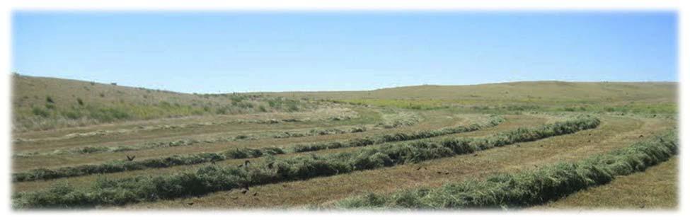
34 Operation - 17 & 19 Vortex Tedder Figure 19 VT-027 With the tractor proceeding and the working rotary group s rotation and therefore of the teeth, the hay aeration process begins. The teeth skims and scrapes the surface and collects the cut crop pushing it the rear in order to spread it evenly [Figure 19]. Figure 20 VT-028 For best results rotary groups must operate at an angle to the ground, which can vary from 7 to 10, as shown in [Figure 20]. 34
35 Operation - 17 & 19 Vortex Tedder Figure 21 DANGER DANGER DANGER DANGER VT-019 NOTE: The reference rotation of the rotary groups is determined by the central ones that rotate respectively clockwise the left group and counter clockwise the right group [Figure 21]. Operate for a few meters and then check the result of the process. If the operator deems appropriate to increase or decrease the angle of the rotary groups to the ground to improve the work process. (See Adjusting Rotating Group Tilt on page 27.) 35
36 Operation - 17 & 19 Vortex Tedder TRANSPORTING Requirements Transport Position Figure 22 Comply with federal, state, local and provincial laws regarding the transport of farm equipment on public roadways. 1 AVOID SERIOUS INJURY OR DEATH Use of an unapproved hitch or tractor / tow vehicle can result in loss of control, leading to serious injury or death. 12 Tractor / tow vehicle and hitch must have the rated capacity to tow equipment. VT-017 AVOID SERIOUS INJURY OR DEATH Excess weight will greatly increase tractor stopping distance and may cause the operator to lose control of the tractor or tow vehicle. Acting on the corresponding lever in the cabin, give completely retract the two rams and raise the two external sections until the two mechanical locking devices (Item 1) [Figure 22] (one for each side) attach to their corresponding stops placed on them. Lock in transport position. Figure 23 Towing Vehicle / Tractor must have adequate braking capacity to safely control GVW trailing load. Do not tow over 20 mph (32 km/h). Towing Vehicle / Tractor unit should weigh approximately 67% of GVW. Verify that the tractor / tow vehicle is approved for transporting the equipment and that the equipment is securely attached to the tractor / tow vehicle. VT-015 Verify safety chain is installed and properly connected before transporting equipment. Verify that the SMV (Slow Moving Vehicle) emblem, all lights and reflectors are clean and visible. Transporting Tedder [Figure 23]. VT
37 Maintenance - 17 & 19 Vortex Tedder MAINTENANCE TROUBLESHOOTING Pull-Type Models SERVICE SCHEDULE Maintenance Intervals LUBRICATION Recommendations Locations TEETH REPLACEMENT Removal And Installation SAFETY SIGN (DECAL) INSTALLATION Procedure STORAGE AND RETURN TO SERVICE Storage Return To Service
38 38 Maintenance - 17 & 19 Vortex Tedder
39 Maintenance - 17 & 19 Vortex Tedder TROUBLESHOOTING Pull-Type Models Instructions are necessary before operating or servicing equipment. Read and understand the Operator And Parts Manual and safety signs (decals) on equipment. Follow warnings and instructions in the manuals when making repairs, adjustments or servicing. Check for correct function after adjustments, repairs or service. Untrained operators and failure to follow instructions can cause injury or death. NOTE: If a problem is encountered that is difficult to solve, even after having read through this troubleshooting section, please call your local distributor or dealer. Before you call, please have this Operator And Parts Manual and the serial number of your machine at hand. PROBLEM CAUSE CORRECTION Hydraulic functions operating. Hydraulic oil level low. Check hydraulic oil level. Fill hydraulic oil as needed. Damaged hydraulic hose or loose connection. Check all hoses and connections. Repair or replace as needed. Hydraulic pump damaged. Check tractor s hydraulic system. Hydraulic oil filter plugged. Clean or replace hydraulic oil filter. Hydraulic functions operating Air in hydraulic system. Remove air from hydraulic system. intermittently. Hydraulic cylinders not holding Worn hydraulic seals in cylinders. Replace seals. position. Overheated hydraulic oil. Hydraulic oil filter plugged. Clean or replace hydraulic oil filter. Crushed hydraulic hose / line. Repair or replace hydraulic hose / line. Oil level low. Fill hydraulic oil as needed. Losing hydraulic oil. Damaged hydraulic hose or loose Check all hoses and connections. connection. Repair or replace as needed. Worn hydraulic seals in cylinders. Replace seals. 39
40 Maintenance - 17 & 19 Vortex Tedder SERVICE SCHEDULE Maintenance Intervals Maintenance work must be done at regular intervals. Failure to do so will result in excessive wear and early failures. The service schedule is a guide for correct maintenance of the Tedder. Instructions are necessary before operating or servicing equipment. Read and understand the Operator and Parts Manual and safety signs (decals) on equipment. Follow warnings and instructions in the manuals when making repairs, adjustments or servicing. Check for correct function after adjustments, repairs or service. Untrained operators and failure to follow instructions can cause injury or death. SERVICE PROCEDURES # DESCRIPTION Check Clean Lube Change Adjust Drain Locations Daily Maintenance (or every 8 hours) 1 Tire Pressure 2 Wheel Bolts 3 Hydraulic Hoses And Connections 4 Hydraulic Cylinders Weekly (or every 50 hours) 5 Hydraulic Hoses And Connections 6 Hydraulic Cylinders 7 Check All Hardware And Safety Devices. 8 Tedder Condition 40

41 Maintenance - 17 & 19 Vortex Tedder LUBRICATION Locations Recommendations Always use a good quality multi-purpose / lithium base grease when lubricating the equipment. Do not over-grease. Greasing too often can lead to premature component failure. Fluid such as engine oil, hydraulic fluid, coolants, grease, etc. must be disposed of in an environmentally safe manner. Some regulations require that certain spills and leaks on the ground must be cleaned in a specific manner. See local, state and federal regulations for the correct disposal. Always use a hand-held grease gun. Figure 24 Clean fitting before greasing, to avoid injecting dirt and grit. Replace and repair broken fittings immediately. If fittings will not take grease, remove and clean thoroughly. Replace fitting if necessary. NOTE: Note: all types of hay tedders have a grease lubricated transmission transfer case which means that all internal components can only operate if they are immersed in the lubricant. Consequently, if they are not grease lubricated they are subject to a rapid wear out and therefore to seizure. Therefore, if the operator observes any loss or leakages from the box, it is essential to check the grease level inside. To check simply unscrew the cap level on the side of the head as shown in the figure. 1 VT-035 Periodically check the grease level inside the case (Item 1) [Figure 24], in order to refilling it using a pump. For filling the case use only grease type AGIP GREASE MU EP2 (ISO L-X-BCHB 2. o DIN KP2K-20). 41
42 Maintenance - 17 & 19 Vortex Tedder TEETH REPLACEMENT Removal And Installation SAFETY SIGN (DECAL) INSTALLATION Procedure AVOID INJURY OR DEATH Before you leave the operator s position: Always park on a flat level surface. Place all controls in NEUTRAL. Engage the park brake. Stop the engine and remove the key. Wait for all moving parts to stop. Figure VT-036 If teeth replacement were necessary (worn or broken), you must completely unscrew the locking nut (Item 1), extract from its seat the fastening screw (Item 2) with its teeth-stop plate (Item 3) and then pull the pair of teeth (Item 4) from the machinery s arm (Item 5) [Figure 25]. Insert a new pair and proceed in reverse order the phases described for the removal. 1 4 When replacing safety signs (decals), the temperature must be above 10 C (50 F). Remove all portions of the damaged safety sign (decal). Thoroughly clean the area with glass cleaner. Remove all adhesive residue. Allow the area to dry completely before installing the new safety sign (decal). Position the safety sign (decal) in the correct location. Remove a small portion of the backing paper on the safety sign (decal). Press on the safety sign (decal) where the backing paper has been removed. Slowly remove the remaining backing paper, pressing on the safety sign (decal) as the backing paper is removed. Using the backing paper, pressing firmly, move the backing paper over the entire safety sign (decal) area. NOTE: Small air pockets can be pierced with a pin and smoothed out using the piece of the backing paper. 42
43 Maintenance - 17 & 19 Vortex Tedder STORAGE AND RETURN TO SERVICE Storage Sometimes it may be necessary to store your Farm King Tedder for an extended period of time. Below is a list of items to perform before storage. DO NOT permit children to play on or around the stored machine. Thoroughly clean the equipment. Lubricate the equipment. Inspect the hitch and all welds on the equipment for wear and damage. Check for loose hardware, missing guards, or damaged parts. Check for damaged or missing safety signs (decals). Replace if necessary. Replace worn or damaged parts. Touch up all paint nicks and scratches to prevent rusting. Store the Tedder in a clean, dry, sheltered area. Place the equipment flat on the ground. Return To Service After the Farm King Tedder has been in storage, it is necessary to follow a list of items to return the equipment to service. Be sure all shields and guards are in place. Lubricate the equipment. Clean and inspect pusher chain for excessive wear or stiffness. Check for proper adjustment and alignment. Inspect and repack wheel bearings with a SAE multi purpose type grease. Check that tires are properly inflated. Connect to a tractor and operate equipment, verify all functions operate correctly. Check for leaks. Repair as needed. Review the Operator s Manual. 43
44 44 Maintenance - 17 & 19 Vortex Tedder
45 Parts Identification - 17 & 19 Vortex Tedder PARTS IDENTIFICATION GENERAL INFORMATION BASE FRAME Lateral Arm Assembly Crossmember Assembly Rear Frame Assembly Hitch Assembly Hydraulic Assembly Guard Assembly Front Frame Assembly Tension Cylinder Assembly Hydraulic Cylinder Assembly Rod Assembly PTO Driveline Assembly (GV & GVL) PTO Driveline Assembly (GVEL)
46 46 Parts Identification - 17 & 19 Vortex Tedder
47 Parts - 17 & 19 Vortex Tedder GENERAL INFORMATION The parts identification section lists descriptions, part numbers and quantities for the Tedder. Contact your Farm King dealer for additional Tedder parts information. 47
48 Parts - 17 & 19 Vortex Tedder BASE FRAME Lateral Arm Assembly , , , , , VT
49 Parts - 17 & 19 Vortex Tedder ITEM PART NUMBER DESCRIPTION QTY 1 R HAY TEDDEER GEARBOX 2 R LATERAL ARM DX GVL 2A R LATERAL ARM DX GV 2B R LATERAL ARM DX GVEL 3 R LATERAL ARM SX GVL 3A R LATERAL ARM SX GV 3B R LATERAL ARM SX GVEL 4 R SCREW, TE M14 x 190 ZN 5 R SELF LOCKING NUT, M10 6 R PLUG, 3/4 7 R COPPER WASHER, 3/4 8 R BEVEL PINION CENTRAL BOX 9 R BEARING, RS 10 R SLEEVE 11 R SHAFT PDF 12 R BEARING, RS 13 R SNAP RING E R CIR CLIP D R SCREW, TE 8 x R WASHER, M12 S.E. 17 R SPACER, 54 x 45 x 8 18 R CIR CLIP D R TAB, 8 x 7 x R SCREW, TE M12 x R WASHER, M12 S.E. 22 R PIN, Ø30 L R GREASE ZERK, M8 x 1 24 R SCREW, TE M12 x 120 ZN 25 R BEVEL PINION FOR ROTOR 26 R COMPLETE DRAFT SUPPORT 27 R CENTRAL CLOSING HOUSING 28 R SCREW, TE M8 x R NUT, M8 30 R SCREW, TE M8 x 30 ZN 31 R SELF LOCKING NUT, M8 32 R PLATE 33 R SHAFT TRASMISSION GVL L A R SHAFT TRASMISSION GV.1418 MM 33B R SHAFT TRASMISSION GVEL L.1783 MM 49
50 Parts - 17 & 19 Vortex Tedder Lateral Arm Assembly (Cont d) , , , , , VT
51 Parts - 17 & 19 Vortex Tedder ITEM PART NUMBER DESCRIPTION QTY 34 R TAB, 8 x 7 x R TAB, 8 x 7 x R CENTRAL PIN WITH BRACKET 37 R SCREW, TCEI M12 x R BEARING R or R BEVEL CROWN FOR ROTOR 40 R or R SAFETY LOOP 41 R BEARING 32007A 42 R PROTECTION SCREEN 43 R ARM CONNECTION FLANGE 44 R NILOS RING, AV 45 R BUSHING, D 54 L R ELASTIC PIN, 10 x R ELASTIC PIN, 6 x R- 49 R- 50 R BEARING RS 51 R SPACER, 42 x 8 x R CROWN FOR CENTRAL BOX 53 R ARM GV 53A R ARM GVL 53B R ARM GVEL 54 R SCREW, TE M12 x 45 ZN 55 R TINE 56 R SPRING CLAMP 57 R SELF LOCKING NUT, M12 58 R SCREW, TE M12 x 30 ZN 59 R- 60 R COLLAR 61 R ARM COMPLETE GV 61A R ARM COMPLETE GVL 61B R ARM COMPLETE GVEL 62 R AXIAL WASHER PS
52 Parts - 17 & 19 Vortex Tedder Crossmember Assembly , VT
53 Parts - 17 & 19 Vortex Tedder ITEM PART NUMBER DESCRIPTION QTY 1 R CROSS ATTACK GVL L.1365 MM 1A R CROSS ATTACK GVEL L.1590 MM 1B R CROSS ATTACK GV L.1224 MM 2 R COLLAR C3 3 R SCREW, TE M12 x 70 4 R WASHER M12 S.E. 5 R BAND 6 R COVER 7 R JOINT DOUBLE DG2 8 R SPACER D.42 L.8 9 R ELASTIC PIN 10 x R ELASTIC PIN 6 x R SHAFT GVL L.916 MM 11A R SHAFT GV L.616 MM 11B R SHAFT GVEL L.1041 MM 12 R TAB, 8 x 7 x R BEVEL PINION FOR ROTOR 14 R SHEET METAL SCROLL 15 R DUST COVER CUP 16 R U-BOLT, M10 17 R RING SEEGER I62 18 R SUPPORT SHAFT 19 R BEARING RS 20 R LATERAL ARM GVL 20A R LATERAL ARM GV 20B R LATERAL ARM GVEL 21 R AXLE FENDER SX 22 R INTERNAL SHIELD 23 R BEARING RS 24 R WHEEL, 16 / 650 / 8 25 R SPACER 26 R EXTERNAL SHIELD 27 R WASHER M16 ZN 28 R SELF LOCKING NUT M16 29 R AXLE FENDER DX 30 R SELF LOCKING NUT M8 31 R PLATE 32 R SCREW, TE M8 x R SCREW, TE M8 x 16 ZN 34 R DUST COVER CUP 35 R BASE COLLAR 53
54 Parts - 17 & 19 Vortex Tedder Rear Frame Assembly , VT
55 Parts - 17 & 19 Vortex Tedder ITEM PART NUMBER DESCRIPTION QTY 1 R CYLINDER G4V 1A R CYLINDER G4VL 1B R CYLINDER G4VLEL 2 R END POINT D.50 3 R WASHER, M16 ZN 4 R SELF LOCKING NUT, M8 5 R WASHER, M22 ZN 6 R SPRING, D.27 L.78 7 R STOP FRAME 8 R PIN HYDRAULIC CYLINDER D20 L100 9 R WASHER, M20 10 R SEEGER, E20 11 R PIN 12 R WASHER, 53 x 26 x 5 13 R RING SEEGER, D R SCREW, TE M10 x 25 ZN 15 R SEAT SHAFT, GVL GVEL 15A R SEAT SHAFT GV 16 R SPRING GVL GVEL 16A R SPRING GV 17 R SLIDING SHAFT GVL GVEL 17A R SLIDING SHAFT GV 18 R PIN HYDRAULIC CYLINDER D16 L72 19 R ROLLER 20 R RING SEEGER D R SELF LOCKING NUT M12 22 R GREASE ZENK M6 x 1 23 R or R AXLE DX 24 R INTERNAL SHIELD 25 R BEARING RS 26 R SPACER 27 R WHEEL COMPLETE, 16 / 650 / 8 28 R EXTERNAL SHIELD 29 R WASHER M16 ZN 30 R SELF LOCKING NUT M16 31 R AXLE SX R PROTECTION SX GVL 33A R PROTECTION SX GVEL 33B R PROTECTION SX GV 34 R PROTECTION DX GVL 34A R PROTECTION DX GVEL 34B R PROTECTION DX GV 35 R RUBBER CUP 36 R BLOCK GVL 36A R BLOCK GVEL 36B R BLOCK GV 37 R SCREW, TPSEI M8 x 25 ZN 38 R WASHER, S.E. M12 55
56 Parts - 17 & 19 Vortex Tedder Hitch Assembly VT
57 Parts - 17 & 19 Vortex Tedder ITEM PART NUMBER DESCRIPTION QTY 1 R HITCH 2 R FRONT PROTECTION GVL L A R FRONT PROTECTION GV L R RUBBER CUP Ø32 4 R STAND 5 R PIN 6 R ELASTIC PIN, 5 x R PIN 8 R WASHER, M20 ZN 9 R SELF LOCKING NUT, M20 10 R COLLAR, CF2 11 R COLLAR, C3 12 R U-BOLT, M10 13 R CARDAN SHAFT, GV-GVL 90 KG/M L A R CARDAN SHAFT, GVEL 120 KG/M L R BASE COLLAR 57
58 Parts - 17 & 19 Vortex Tedder Adjustment Handle Assembly VT-005 ITEM PART NUMBER DESCRIPTION QTY 1 R ROPE 2 R HANDLE 3 R SCREW REGULATION 4 R SNAIL M24 L.55 5 R ELASTIC PIN, 6 x 36 6 R WASHER, AS R HANDLE 8 R FRONTE SNAIL 9 R SEEGER, D R ATTACK REGULATION 11 R PLATE ATTACK 12 R GROWER WASHER, M16 13 R SCREW, TE M16 x 110 ZN 14 R HANDLE STOP 15 R SPLIT PIN, 3 x R CRICKET, Ø8 58
59 Parts - 17 & 19 Vortex Tedder Hydraulic Assembly 3, H MODEL ONLY VT-006 ITEM PART NUMBER DESCRIPTION QTY 1 R ATTACK CYLINDER 2 R PLATE ATTACK 3 R SCREW, TE M16 x 110 ZN 4 R GROWER WASHER, M16 5 R CYLINDER 6 R SEEGER, E20 7 R PIN HYDRAULIC CYLINDER, D20 L100 8 R PIN Ø25 L R BUSH 10 R SCREW, TEM 6 x 55 ZN 11 R SELF LOCKING NUT, M6 12 R HYDRUALIC HOSE L R HYDRUALIC HOSE L R HYDRUALIC HOSE L
60 Parts - 17 & 19 Vortex Tedder Guard Assembly VT
61 Parts - 17 & 19 Vortex Tedder ITEM PART NUMBER DESCRIPTION QTY 1 R FRONT PROTECTION DX GVL 1A R FRONT PROTECTION DX GV 2 R FRONT PROTECTION SX GVL 2A R FRONT PROTECTION SX GV 3 R RUBBER CUP Ø32 4 R U-BOLT, M10 5 R UNION PROTECTION 6 R U-BOLT, M10 x 40 7 R PROTECTION BACK DX G4VL 7A R PROTECTION BACK DX G4V 8 R PROTECTION BACK SX GVL 8A R PROTECTION BACK SX G4V 9 R CONNECTION PROTECTION 10 R SCREW, TE M8 x 45 ZN 11 R SELF LOCKING NUT M8 12 R SCREW, TE M16 x 16 ZN 13 R WASHER, M6 EXL ZN 14 R SELF LOCKING NUT M6 15 R PANEL 16 R BASE COLLAR 61

62 Parts - 17 & 19 Vortex Tedder Front Frame Assembly , 32 28, , VT
63 Parts - 17 & 19 Vortex Tedder ITEM PART NUMBER DESCRIPTION QTY 1 R FRAME 2 R SCREW, TE M16 x 120 ZN 3 R SELF LOCKING NUT, M16 4 R SUPPORT ROPE, 3P 5 R SCREW, TE M12 L20 ZN 6 R WASHER, M12 ZN 7 R ELASTIC PIN, 8 x 50 8 R BUSHING 9 R BUSH GLYCODUR, R SUPPORT 11 R BUSHING 12 R WASHER, M22 ZN 13 R SELF LOCKING NUT, M22 14 R P ATTACK 15 R STAND 16 R ELASTIC PIN 17 R PIN, Ø10 18 R BRACKET 19 R SCREW, TE M16 x 110 ZN 20 R PIN, Ø22 L R WASHER, M22 ZN 22 R ELASTIC PIN, 6X30 23 R COLLAR 24 R PIN 2 25 R PIN 26 R HOOK 27 R SCREW, TE M12 L ZN 28 R WASHER, M12 ZN 29 R SELF LOCKING NU,T M12 30 R SCREW, TE M8 x R PIN, Ø28 L R SELF LOCKING NUT, M8 33 R PIN, 3 POINT 34 R CARDAN SHAFT, 900 NM L.1480 GVL GV 35 R HANDLE 36 R ROPE 37 R U-BOLT, M10 38 R BASE COLLAR 63
64 Parts - 17 & 19 Vortex Tedder Tension Cylinder Assembly VT
65 Parts - 17 & 19 Vortex Tedder ITEM PART NUMBER DESCRIPTION QTY 1 R PIN 2 R WASHER, Ø40 3 R CILINDER 4 R WASHER, M20 ZN 5 R SELF LOCKING NUT, M20 6 R SCREW, TE M8 x 90 ZN 7 R SUPPORT SPRING 8 R SPRING 9 R BRAKE 10 R WASHER, M8 EXL ZN 11 R SELF LOCKING NUT, M8 12 R SPRING 13 R ROD 14 R HYDRUALIC HOSE, L.1350 MM 15 R HYDRUALIC HOSE, L
66 Parts - 17 & 19 Vortex Tedder Hydraulic Cylinder Assembly VT-010 ITEM PART NUMBER DESCRIPTION QTY 1 R SUPPORT 2 R HANDLE 3 R BUSHING 4 R ELASTIC PIN, 6 x 40 5 R ROD 6 R HEAD 7 R COMPLETE SEAL KIT 8 R SELF LOCKING NUT, M20 9 R CYLINDER W / VALVE 10 R COMPLETE CYLINDER, Ø50 C
67 Parts - 17 & 19 Vortex Tedder Rod Assembly VT-011 ITEM PART NUMBER DESCRIPTION QTY 1 R ROD GV 1A R ROD GVL 1B R ROD GVEL 2 R HEAD 3 R SEAL KIT GV 3A R SEAL KIT GVL 3B R SEAL KIT GVEL 4 R CYLINDER GV 4A R CYLINDER GVL 4B R CYLINDER GVEL 5 R COMPLETE CYLINDER GV 5A R COMPLETE CYLINDER GVL 5B R COMPLETE CYLINDER GVEL 67
68 Parts - 17 & 19 Vortex Tedder PTO Driveline Assembly (GV & GVL) VT-012 ITEM PART NUMBER DESCRIPTION QTY 1 R FORK 2 R CROSS 3 R FORK SPLINED 4 R TUBE EXT. L R TUBE INT. L R FORK INT. 7 R LIMITING 8 R ELASTIC PIN 8X55 DIN R EXTERNAL PROTECTION L R INTERNAL PROTECTION L
69 Parts - 17 & 19 Vortex Tedder PTO Driveline Assembly (GVEL) VT-012 ITEM PART NUMBER DESCRIPTION QTY 1 R FORK 2 R CROSS 3 R FORK SPLINED 4 R TUBE EXT. L R TUBE INT. L R FORK INT. 7 R LIMITING 8 R ELASTIC PIN 8 x 55 DIN R EXTERNAL PROTECTION L R INTERNAL PROTECTION L
70 70 Parts - 17 & 19 Vortex Tedder
71 Specifications - 17 & 19 Vortex Tedder SPECIFICATIONS SPECIFICATIONS Dimensions Performance HARDWARE TORQUE VALUES Metric Chart Imperial Chart HYDRAULIC CONNECTION SPECIFICATIONS O-Ring Fitting (Straight Thread) O-ring Face Seal Connection Flare Fitting Port Seal (O-ring Boss) Fitting Tubelines And Hoses
72 72 Specifications - 17 & 19 Vortex Tedder
73 Specifications - 17 & 19 Vortex Tedder SPECIFICATIONS Dimensions DESCRIPTION 17 FT 19 FT Transport Width 9 ft. 2 in. (280 cm) 10 ft. 5 in. (320 cm) Working Width 17 ft. (520 cm) 19 ft. (570 cm) Performance DESCRIPTION 17 FT 19 FT Weight 1275 lb. (578 kg) 1400 lb. (635 kg) Rotors / Arms Per Rotor 4 / 6 4 / 6 Tires 4, 16 x 6.50 x 8 ply 4, 16 x 6.50 x 8 ply PTO Speed 540 rpm 540 rpm Tractor HP 20 hp (15kW) 20 hp (15kW) 73
74 Specifications - 17 & 19 Vortex Tedder HARDWARE TORQUE VALUES Metric Chart NOTE: Do not use the values listed in the charts if a different torque value or tightening procedure is specified in this manual for a specific application. Torque values listed are for general use only. Use the following charts to determine the correct torque when checking, adjusting or replacing hardware. Torque values are listed in newton-meters (inch* or foot pounds) for normal assembly applications. Nominal Size Class 5.8 Class 8.8 Class 10.9 Lock nuts Unplated Plated W / ZnCr Unplated Plated W / ZnCr Unplated Plated W / ZnCr CL.8 w/ CL. 8.8 Bolt M4 1.7 (15*) 2.2 (19*) 2.6 (23*) 3.4 (30*) 3.7 (33*) 4.8 (42*) 1.8 (16*) M6 5.8 (51*) 7.6 (67*) 8.9 (79*) 12 (102*) 13 (115*) 17 (150*) 6.3 (56*) M8 14 (124*) 18 (159*) 22 (195*) 28 (248*) 31 (274*) 40 (354*) 15 (133*) M10 28 (21) 36 (27) 43 (32) 56 (41) 61 (45) 79 (58) 30 (22) M12 49 (36) 63 (46) 75 (55) 97 (72) 107 (79) 138 (102) 53 (39) M (89) 158 (117) 186 (137) 240 (177) 266 (196) 344 (254) 131 (97) M (175) 307 (226) 375 (277) 485 (358) 519 (383) 671 (495) 265 (195) M (303) 531 (392) 648 (478) 839 (619) 897 (662) 1160 (855) 458 (338) NOTE: Torque values shown with * are inch pounds. Identification of Hex Cap Screws and Carriage Bolts - Classes 5 and up MANUFACTURER S IDENTIFICATION XYZ AB CD PROPERTY CLASS Identification of Hex Nuts and Lock Nuts - Classes 5 and up MANUFACTURER S IDENTIFICATION AB 8 AB 8 AB PROPERTY CLASS 74
75 Specifications - 17 & 19 Vortex Tedder HARDWARE TORQUE VALUES (CONT D) Imperial Chart NOTE: Do not use the values listed in the charts if a different torque value or tightening procedure is specified in this manual for a specific application. Torque values listed are for general use only. Use the following charts to determine the correct torque when checking, adjusting or replacing hardware. Torque values are listed in newton-meters (inch* or foot pounds) for normal assembly applications. Nominal SAE Grade 5 SAE Grade 8 LOCK NUTS Size Unplated or Plated Plated W / ZnCr Unplated or Plated Plated W / ZnCr Unplated or Plated Plated W / ZnCr Grade W / Gr. 5 Bolt Grade W / Gr. 8 Bolt Silver Gold Silver Gold Silver Gold 1/4 6.2 (55*) 8.1 (72*) 9.7 (86*) 12.6 (112*) 13.6 (121*) 17.7 (157*) 6.9 (61*) 9.8 (86*) 5/16 13 (115*) 17 (149*) 20 (178*) 26 (229*) 28 (250*) 37 (324*) 14 (125*) 20 (176*) 3/8 23 (17) 30 (22) 35 (26) 46 (34) 50 (37) 65 (48) 26 (19) 35 (26) 7/16 37 (27) 47 (35) 57 (42) 73 (54) 80 (59) 104 (77) 41 (30) 57 (42) 1/2 57 (42) 73 (54) 87 (64) 113 (83) 123 (91) 159 (117) 61 (45) 88 (64) 9/16 81 (60) 104 (77) 125 (92) 163 (120) 176 (130) 229 (169) 88 (65) 125 (92) 5/8 112 (83) 145 (107) 174 (128) 224 (165) 244 (180) 316 (233) 122 (90) 172 (127) 3/4 198 (146) 256 (189) 306 (226) 397 (293) 432 (319) 560 (413) 217 (160) 306 (226) 7/8 193 (142) 248 (183) 495 (365) 641 (473) 698 (515) 904 (667) 350 (258) 494 (364) (213) 373 (275) 742 (547) 960 (708) 1048 (773) 1356 (1000) 523 (386) 739 (545) NOTE: Torque values shown with * are inch pounds. Identification of Hex Cap Screws and Carriage Bolts SAE GRADE 2 BOLTS SAE GRADE 5 BOLTS SAE GRADE 8 BOLTS SAE GRADE 2 NUTS SAE GRADE 5 NUTS SAE GRADE 8 NUTS Identification of Hex Nuts and Lock Nuts Grade A - No Notches B Grade A - No Mark Grade A - No Marks Grade B - One Circumferential Notch Grade C - Two Circumferential Notches Grade B - Letter B Grade C - Letter C Grade B - Three Marks Grade C - Six Marks (Marks not always located at corners) 75
76 Specifications - 17 & 19 Vortex Tedder HYDRAULIC CONNECTION SPECIFICATIONS O-Ring Fitting (Straight Thread) Lubricate the O-ring before installing the fitting. Loosen the jam nut and install the fitting. Tighten the jam nut until the washer is tight against the surface. O-ring Face Seal Connection Figure 26 O-ring Face Seal Tightening Torque Tubeline O.D. Thread Size N m (ft-lb) 1/4 9/ (18) 3/8 11/ (30) 1/2 13/ (54) 5/ (81) 3/4 1-3/ (114) 7/8 1-3/ (133) 1 1-7/ (160) 1-1/4 1-11/ (209) 1-1/ (221) When the fitting is tightened, you can feel when the fitting is tight to eliminate leakage caused by under or over torqued fittings. Use petroleum jelly to hold the O-ring in position until the fittings are assembled. Flare Fitting Figure 27 Flare Fitting Tightening Torque Tubeline O.D. Thread Size N m (ft-lb) 1/4 7/ (18) 5/16 1/ (23) 3/8 9/ (30) 1/2 3/ (54) 5/8 7/ (81) 3/4 1-1/ (114) 7/8 1-3/ (133) 1 1-5/ (160) 1-1/4 1-5/ (209) 1-1/2 1-7/ (221) 2 2-1/ (342) Tighten until the nut makes contact with the seat. Use the chart [Figure 27] to find the correct tightness needed. Port Seal (O-ring Boss) Fitting Figure 28 Port Seal And O-ring Boss Tightening Torque Tubeline O.D. Thread Size N m (ft-lb) 1/4 7/ (18) 3/8 9/ (30) 1/2 3/ (54) 5/8 7/ (81) 3/4 1-1/ (114) 7/8 1-3/ (133) 1 1-5/ (160) 1-1/8 1-7/ (209) 1-1/4 1-5/ (221) NOTE: Port seal and nut, washer and O-ring (O-ring Boss) fittings use the same tightening torque valve chart. If a torque wrench cannot be used, use the following method. Tighten the nut until it just makes metal to metal contact, you can feel the resistance. Tighten the nut with a wrench no more than one hex flat maximum. Do not over tighten the port seal fitting. NOTE: If a torque wrench cannot be used, use the hex flat tightening method as an approximate guideline. NOTE: Port seal fittings are not recommended in all applications. Use O-ring boss fittings in these applications. Tubelines And Hoses Replace any tubelines that are bent or flattened. They will restrict flow, which will slow hydraulic action and cause heat. Replace hoses which show signs of wear, damage or weather cracked rubber. Always use two wrenches when loosening and tightening hose or tubeline fittings. NOTE: If the fitting leaks, disconnect and inspect the seat area for damage. 76
77 Warranty - 17 & 19 Vortex Tedder WARRANTY WARRANTY
78 78 Warranty - 17 & 19 Vortex Tedder
79 Warranty - 17 & 19 Vortex Tedder WARRANTY Limited Warranty BASE LIMITED WARRANTY Farm King provides this warranty only to original retail purchasers of its products. Farm King warrants to such purchasers that all Farm King manufactured parts and components used and serviced as provided for in the Operator s Manual shall be free from defects in materials and workmanship for a period following delivery to the original retail purchaser of one (1) year. This limited warranty applies only to those parts and components manufactured by Farm King. Parts and components manufactured by others are subject to their manufacturer s warranties, if any. Farm King will fulfill this limited warranty by, at its option, repairing or replacing any covered part that is defective or is the result of improper workmanship, provided that the part is returned to Farm King within thirty (30) days of the date that such defect or improper workmanship is, or should have been, discovered. Parts must be returned through the selling representative and the buyer must prepay transportation charges. Farm King will not be responsible for repairs or replacements that are necessitated, in whole or part, by the use of parts not manufactured by or obtained from Farm King. Under no circumstances are component parts warranted against normal wear and tear. There is no warranty on product pump seals, product pump bearings, rubber product hoses, pressure gauges, or other components that require replacement as part of normal maintenance. REPAIR PARTS LIMITED WARRANTY Farm King warrants genuine Farm King replacement parts purchased after the expiration of the Farm King Limited Warranty, and used and serviced as provided for in the Operator s Manual, to be free from defects in materials or workmanship for a period of thirty (30) days from the invoice date for the parts. Farm King will fulfill this limited warranty by, at its option, repairing or replacing any covered part that is defective or is the result of improper workmanship, provided that the part is returned to Farm King within thirty (30) days of the date that such defect or improper workmanship is, or should have been, discovered. Such parts must be shipped to the Farm King factory at the purchaser s expense. WHAT IS NOT COVERED Under no circumstances does this limited warranty cover any components or parts that have been subject to the following: negligence; alteration or modification not approved by Farm King; misuse; improper storage; lack of reasonable and proper maintenance, service, or repair; normal wear; damage from failure to follow operating instructions; accident; and/or repairs that have been made with parts other than those manufactured, supplied, and / or authorized by Farm King. AUTHORIZED DEALER AND LABOR COSTS Repairs eligible for labor under this limited warranty must be made by Farm King or an authorized Farm King dealer. Farm King retains the exclusive discretion to determine whether it will pay labor costs for warranty repairs or replacements, and the amount of such costs that it will pay and the time in which the repairs will be made. If Farm King determines that it will pay labor costs for warranty work, it will do so by issuing a credit to the dealer s or distributor s account. Farm King will not approve or pay invoices sent for repairs that Farm King has not previously approved. Warranty service does not extend the original term of this limited warranty. 79
80 Warranty - 17 & 19 Vortex Tedder Limited Warranty WARRANTY REQUIREMENTS To be covered by warranty, each new product must be registered with Farm King within thirty (30) days of delivery to original retail purchaser. If the customer decides to purchase replacement components before the warranty disposition of such components is determined, Farm King will bill the customer for such components and then credit the replacement invoice for those components later determined to be covered by this limited warranty. Any such replacement components that are determined not be covered by this limited warranty will be subject to the terms of the invoice and shall be paid for by the purchaser. EXCLUSIVE EFFECT OF WARRANTY AND LIMITATION OF LIABILITY TO THE EXTENT PERMITTED BY LAW, FARM KING DISCLAIMS ANY WARRANTIES, REPRESENTATIONS, OR PROMISES, EXPRESS OR IMPLIED, AS TO THE QUALITY, PERFORMANCE, OR FREEDOM FROM DEFECT OF THE COMPONENTS AND PARTS COVERED BY THIS WARRANTY AND NOT SPECIFICALLY PROVIDED FOR HEREIN. TO THE EXTENT PERMITTED BY LAW, FARM KING DISCLAIMS ANY IMPLIED WARRANTIES OF MERCHANTABILITY AND FITNESS FOR A PARTICULAR PURPOSE ON ITS PRODUCTS COVERED HEREIN, AND DISCLAIMS ANY RELIANCE BY THE PURCHASER ON FARM KING S SKILL OR JUDGMENT TO SELECT OR FURNISH GOODS FOR ANY PARTICULAR PURPOSE. THE PURCHASER S ONLY AND EXCLUSIVE REMEDIES IN CONNECTION WITH THE BREACH OR PERFORMANCE OF ANY WARRANTY ON FARM KING S PRODUCTS ARE THOSE SET FORTH HEREIN. IN NO EVENT SHALL FARM KING BE LIABLE FOR INCIDENTAL OR CONSEQUENTIAL DAMAGES (INCLUDING, BY WAY OF EXAMPLE ONLY AND NOT LIMITATION, LOSS OF CROPS, LOSS OF PROFITS OR REVENUE, OTHER COMMERCIAL LOSSES, INCONVENIENCE, OR COST OF REPLACEMENT OF RENTAL EQUIPMENT). IN NO EVENT SHALL FARM KING S CONTRACT OR WARRANTY LIABILITY EXCEED THE PURCHASE PRICE OF THE PRODUCT. (Note that some states do not allow limitations on how long an implied warranty lasts or the exclusion or limitation of incidental or consequential damages, so the above limitations and exclusion may not apply to you.) This warranty gives you specific legal rights and you may also have other rights, which vary from state to state. Farm King neither assumes nor authorizes any person or entity, including its selling representatives, to assume any other obligations or liability in connections with the sale of covered equipment, or to make any other warranties, representations, or promises, express or implied, as to the quality, performance, or freedom from defect of the components and parts covered herein. No one is authorized to alter, modify, or enlarge this limited warranty, or its exclusions, limitations and reservations. Corrections of defects and improper workmanship in the manner, and for the applicable time periods, provided for herein shall constitute fulfillment of all responsibilities of Farm King to the purchaser, and Farm King shall not be liable in negligence, contract, or on any other basis with respect to the subject equipment. This limited warranty is subject to any existing conditions of supply which may directly affect Farm King s ability to obtain materials or manufacturer replacement parts. Buhler Industries Inc. reserves the right to make improvements in design or changes in specifications to its products at anytime, without incurring any obligation to owners of units previously sold. 80
81 Alphabetical Index - 17 & 19 Vortex Tedder ALPHABETICAL INDEX BASE FRAME EQUIPMENT IDENTIFICATION FIRE PREVENTION GENERAL INFORMATION GENERAL INFORMATION HARDWARE TORQUE VALUES HYDRAULIC CONNECTION SPECIFICATIONS INITIAL SET-UP LUBRICATION OWNER S INFORMATION SAFETY INSTRUCTIONS SAFETY SIGN (DECAL) INSTALLATION.. 42 SAFETY SIGN-OFF FORM SAFETY SIGNS (DECALS) SERVICE SCHEDULE SPECIFICATIONS STORAGE AND RETURN TO SERVICE TEETH REPLACEMENT TRANSPORTING TROUBLESHOOTING WARRANTY REGISTRATION FORM WARRANTY

82 82 Alphabetical Index - 17 & 19 Vortex Tedder
OPERATOR AND PARTS MANUAL
 OPERATOR AND PARTS MANUAL Bale Wrapper BW150 052016 R0001 6990633 (1-13) Printed in U.S.A. Bobcat Company 2013 062013 Rev 1 88664296 Table of Contents - BW150 TABLE OF CONTENTS Manufacturer s Statement:
OPERATOR AND PARTS MANUAL
 OPERATOR AND PARTS MANUAL Sickle Bar Mower Model RSB6, RSB7, RSB9 08206 P4723 6990633 (-3) Printed in U.S.A. Bobcat Company 203 06203 Rev 88664296 Table of Contents - Sickle Bar Mower TABLE OF CONTENTS
OPERATOR AND PARTS MANUAL. Snowblower. Model 500, 600, FK311
 OPERATOR AND PARTS MANUAL Snowblower Model 500, 600, 660 062017 FK311 500, 600, 660 Table Of Contents Manufacturer s Statement: For technical reasons, Buhler Industries Inc. reserves the right to modify
OPERATOR AND PARTS MANUAL
 OPERATOR AND PARTS MANUAL Bale Wrapper BW150 052016 R0001 6990633 (1-13) Printed in U.S.A. Bobcat Company 2013 062013 Rev 1 88664296 Table of Contents - BW150 TABLE OF CONTENTS Manufacturer s Statement:
OPERATOR AND PARTS MANUAL. Snowblower. Model 5010, 6010, FK312
 OPERATOR AND PARTS MANUAL Snowblower Model 5010, 6010, 6610 032016 FK312 5010, 6010, 6610 Table Of Contents Manufacturer s Statement: For technical reasons, Buhler Industries Inc. reserves the right to
OPERATOR AND PARTS MANUAL. Double Rotary Rake. Model R0005
 OPERATOR AND PARTS MANUAL Double Rotary Rake Model 7700 10018 R0005 7700 Double Rotary Rake Table Of Contents Manufacturer s Statement: For technical reasons, Buhler Industries Inc. reserves the right
OPERATOR AND PARTS MANUAL. Rotary Tiller 25 Series. Model TL236, TL245, TL FK303
 OPERATOR AND PARTS MANUAL Rotary Tiller 25 Series Model TL236, TL245, TL254 102017 FK303 Rotary Tiller 25 Series Table Of Contents Manufacturer s Statement: For technical reasons, Buhler Industries Inc.
OPERATOR AND PARTS MANUAL. Snowblower. Model FK315
 OPERATOR AND PARTS MANUAL Snowblower Model 960 072017 FK315 960 Table Of Contents Manufacturer s Statement: For technical reasons, Buhler Industries Inc. reserves the right to modify machinery design
OPERATOR AND PARTS MANUAL
 OPERATOR AND PARTS MANUAL Square Bale Carrier Model 4480 204 FK83000068 6990633 (-3) Printed in U.S.A. Bobcat Company 203 06203 Rev 88664296 Table of Contents - Square Bale Carrier 4480 TABLE OF CONTENTS
OPERATOR AND PARTS MANUAL
 OPERATOR AND PARTS MANUAL Backsaver Auger Models 684 &604 0806 FK370 Revision 3 6990633 (-3) Printed in U.S.A. Bobcat Company 03 0603 Rev 8866496 Table of Contents - Backsaver Auger 684 & 604 TABLE OF
OPERATOR AND PARTS MANUAL. Grain Cart Model 1060 and Rev
 OPERATOR AND PARTS MANUAL Grain Cart Model 060 and 360 0703 8866496 6990633 (-3) Printed in U.S.A. Bobcat Company 03 0603 Rev 8866496 Table of Contents - 060 and 360 Grain Cart TABLE OF CONTENTS Manufacturer
OPERATOR AND PARTS MANUAL
 OPERATOR AND PARTS MANUAL Backsaver Auger Model 370, 385, 395 0305 FK35 6990633 (-3) Printed in U.S.A. Bobcat Company 03 0603 Rev 8866496 Table of Contents - 3" Backsaver Auger TABLE OF CONTENTS Manufacturer
OPERATOR AND PARTS MANUAL
 OPERATOR AND PARTS MANUAL Backsaver Auger Model and 04 SZ063 6990633 (-3) Printed in U.S.A. Bobcat Company 03 0603 Rev 8866496 Table of Contents - Backsaver Auger / TABLE OF CONTENTS Manufacturer s Statement:
OPERATOR AND PARTS MANUAL SERIES CONVENTIONAL AUGER MOVER. Models 841, 851, 861, 1041, 1051, FK395
 OPERATOR AND PARTS MANUAL SERIES CONVENTIONAL AUGER MOVER Models 84, 85, 86, 04, 05, 06 07207 FK395 CX2 Conventional Auger Mover TABLE OF CONTENTS Manufacturer s Statement: For technical reasons, Farm
OPERATOR AND PARTS MANUAL. Fertilizer Applicator Model Rev
 OPERATOR AND PARTS MANUAL Fertilizer Applicator Model 460 03206 88663040 6990633 (-3) Printed in U.S.A. Bobcat Company 203 06203 Rev 88664296 Table of Contents - Fertilizer Applicator 460 TABLE OF CONTENTS
Passenger Stair / Crewstair
 Ground Support Equipment April, 204 Revision (0) Date Passenger Stair / Crewstair (A227266D) Operation & Maintenance Manual WASP, Inc. PRINTED IN THE U.S.A. Model A227266D TABLE OF CONTENTS TABLE OF CONTENTS
Mulcher Operators Manual
 Mulcher Operators Manual Skid Pro Attachments PO Box 982 Alexandria, MN 56308 October 2015 1 2 Contents 1. Introduction And Warranty... 4 1.1 Introduction... 4 1.2 Warranty... 4 2. Component Identification...
W & A 12 ROW TOP LEVELING STACKER LEVEL BANDER
 W & A 12 ROW TOP LEVELING STACKER LEVEL BANDER NO. 3640 OPERATOR S MANUAL TO THE OWNER: Congratulations on your purchase of a new W & A Top Leveling Stacker Level Bander. Your selection is an indication
W & A 12 ROW TOP LEVELING STACKER LEVEL BANDER
 W & A 12 ROW TOP LEVELING STACKER LEVEL BANDER NO. 3640 OPERATOR S MANUAL TO THE OWNER: Congratulations on your purchase of a new W & A Top Leveling Stacker Level Bander. Your selection is an indication
BEFORE YOU START!! Read the safety messages on the implement as shown in your manual. Observe the rules of safety and common sense!
 To the Owner/Operator/Dealer All implements with moving parts are potentially hazardous. There is no substitute for a cautious, safe-minded operator who recognizes the potential hazards and follows reasonable
OPERATOR AND PARTS MANUAL. Grain Cleaner. Model FK328
 OPERATOR AND PARTS MANUAL Grain Cleaner Model 480 122017 FK328 480 Grain Cleaner Table Of Contents Manufacturer s Statement: For technical reasons, Buhler Industries Inc. reserves the right to modify
OPERATOR AND PARTS MANUAL. Grain Cleaner. Model FK327
 OPERATOR AND PARTS MANUAL Grain Cleaner Model 360 112017 FK327 360 Grain Cleaner Table Of Contents Manufacturer s Statement: For technical reasons, Buhler Industries Inc. reserves the right to modify
OPERATION MANUAL DBW Bale Wagon DFW Feeder Wagon
 OPERATION MANUAL DBW Bale Wagon DFW Feeder Wagon To the Owner/Operator/Dealer All implements with moving parts are potentially hazardous. There is no substitute for a cautious, safe-minded operator who
Log Splitter. Owner/Operator Manual. Models HCWP1-26
 Log Splitter Owner/Operator Manual Models HCWP1-26 SAFETY..........................2 SAFETY WARNING SYMBOL.........3 SAFETY RULES.................. 4-5 SPECIFICATIONS................. 6 CONTROLS AND FEATURES.......
THREE-POINT SNOW BLOWER OPERATION AND MAINTENANCE MANUAL. 54 Inch 66 Inch 72 Inch
 THREE-POINT SNOW BLOWER OPERATION AND MAINTENANCE MANUAL 54 Inch 66 Inch 72 Inch INTRODUCTION TO THE OWNER: Read this manual before operating your equipment. Keep this manual handy for ready reference.
610 BUSHEL MANURE SPREADER
 610 BUSHEL MANURE SPREADER RODA MANUFACTURING 1008 LOCUST ST. HULL, IA. 51239 Art s-way Manufacturing 712-439-2366 Co., Inc. Hwy 9 West - PO Box 288 WWW.RODAMFG.COM Armstrong, IA. 50514 U.S.A 2 INTRODUCTION
3-Pt. Quick Hitch. Owner s Manual
 3-Pt. Quick Hitch Owner s Manual WARNING: Read carefully and understand all ASSEMBLY AND OPERATION INSTRUCTIONS before operating. Failure to follow the safety rules and other basic safety precautions may
1250 LB. CAPACITY MECHANICAL WHEEL DOLLY
 1250 LB. CAPACITY MECHANICAL WHEEL DOLLY 67287 SET-UP AND OPERATING INSTRUCTIONS Visit our website at: http://www.harborfreight.com Read this material before using this product. Failure to do so can result
ROLLER COMPACTORS OPERATOR S MANUAL MODELS SC6016, SC6016-3PT, SC6020 SC7220-3PT, SC7220, SC8420, SC9620
 ROLLER COMPACTORS OPERATOR S MANUAL MODELS SC6016, SC6016-3PT, SC6020 SC7220-3PT, SC7220, SC8420, SC9620 MANUFACTURER'S LIMITED WARRANTY Manufacturer warrants to original Purchaser that its product is
WARNING this attachments capacity changes depending on the Skid Steer Loader it is hooked up to. CAPACITY AT 24 LOAD CENTER
 SKID STEER FORKLIFT ATTACHMENT Any piece of equipment can be dangerous if not operated properly. YOU are responsible for the safe operation of this equipment. The operator must carefully read and follow
MK AUGERS POWER SWING KIT ASSEMBLY & OPERATION MANUAL
 MK AUGERS POWER SWING KIT ASSEMBLY & OPERATION MANUAL Read this manual before using product. Failure to follow instructions and safety precautions can result in serious injury, death, or property damage.
Trench Filler for Compact Utility Loaders
 Form No. 3353-608 Rev A Trench Filler for Compact Utility Loaders Model No. 22472 260000001 and Up Operator s Manual Register your product at www.toro.com Original Instructions (EN) Contents Page Introduction................................
DRILL 2300 SAFETY SECTION
 DRILL 2300 SAFETY SECTION RECOGNIZE SAFETY ALERT SYMBOL WARNING: KEEP RIDERS OFF UNIT Riding on any agricultural equipment is very dangerous. People can be killed or seriously injured when accidentally
OPERATORS MANUAL FOR KAFURTER ROTARY TOPPERS MODELS: TP110, TP140, TP160, TP170
 OPERATORS MANUAL FOR KAFURTER ROTARY TOPPERS MODELS: TP110, TP140, TP160, TP170 SAFETY WARNING: Do not use or operate this this manual and assembly instructions (where applicable) has been read and understood.
1000-lb Hydraulic Truck Crane
 1000-lb Hydraulic Truck Crane Owner s Manual WARNING: Read carefully and understand all ASSEMBLY AND OPERATION INSTRUCTIONS before operating. Failure to follow the safety rules and other basic safety precautions
3-Pt. Boom Pole. Owner s Manual
 3-Pt. Boom Pole Owner s Manual WARNING: Read carefully and understand all ASSEMBLY AND OPERATION INSTRUCTIONS before operating. Failure to follow the safety rules and other basic safety precautions may
Post Hole Digger. Operation Manual MODEL
 Post Hole Digger MODEL 107798 Operation Manual This safety alert symbol identifies important safety messages in this manual. Failure to follow this important safety information may result in serious injury
SUNDOWN Operation. & Parts Manual. for Box Blade Models BB15-48, 60 BB20-48, 60, 72 BB30-60, 72, 84, & 96
 SUNDOWN Operation & Parts Manual for Box Blade Models BB15-48, 60 BB20-48, 60, 72 BB30-60, 72, 84, & 96 Operations and Parts Manual Table of Contents Section Page Table of Contents 2 Retail Customer Responsibility
Prime Attachments & Custom Fab Brush Mower Owners/Operators Manual
 Prime Attachments & Custom Fab Brush Mower Owners/Operators Manual The operator is responsible for the safe operation and maintenance of the machine. It is important that anyone who uses the machine is
Operator s Manual. Ground Drive Fertilizer Spreader PTS PTS-160
 Operator s Manual Ground Drive Fertilizer Spreader PTS-100 - PTS-160 Publication #: April 2009 TABLE OF CONTENTS INTRODUCTION... 1 SAFETY... 1 SAFETY SIGNAL WORDS... 2 GENERAL SAFETY GUIDELINES... 2 SAFETY
Post Hole Diggers Compact Standard Heavy Duty
 Post Hole Diggers Compact Standard Heavy Duty MODEL 90 / MODEL 100 / MODEL 110 # 100623 # 100498 # 100624 Operation Manual This safety alert symbol identifies important safety messages in this manual.
OPERATOR S MANUAL. 20-bu 3-Point Hitch Material Collection System. LP65048 Supplier ST /07/2017 English. North American Edition Printed in USA
 OPERATOR S MANUAL 20-bu 3-Point Hitch Material Collection System LP65048 Supplier ST48289 11/07/2017 English North American Edition Printed in USA Introduction Using Your Operator s Manual Read this entire
71 South 215 West - Rupert ID, Phone: (208) Fax: (208)
 Fax: (208)") 71 South 215 West - Rupert ID, 83350 Phone: (208) 436-1770 Fax: (208) 436-1776 www.norwest-mfg.com Norwest Pivot Track Filler OWNER S MANUAL 71 SOUTH 215 WEST RUPERT, IDAHO 83350 Phone: (208) 436-1770
71 South 215 West - Rupert ID, 83350 Phone: (208) 436-1770 Fax: (208) 436-1776 www.norwest-mfg.com Norwest Pivot Track Filler OWNER S MANUAL 71 SOUTH 215 WEST RUPERT, IDAHO 83350 Phone: (208) 436-1770
3800 SERIES SINGLE HYDRAULIC LOCKING TOOLBAR
 3800 SERIES SINGLE HYDRAULIC LOCKING TOOLBAR 2565-774_REV_D 02/2018 OPERATOR S MANUAL PART IDENTIFICATION YETTER MANUFACTURING CO. FOUNDED 1930 Colchester, IL 62326-0358 Toll free: 800/447-5777 309/776-3222
Smart-Till. Models ST101, ST151, ST203, and ST303. HCC, inc st Avenue Mendota, IL
 Owners Manual Smart-Till Models ST101, ST151, ST203, and ST303 HCC, inc. 1501 1st Avenue Mendota, IL 61342 815-539-9371 www.hccincorporated.com C-1159 May 2010 Safety Most work related accidents are caused
QUICK ATTACH SNOW PUSHER OPERATION AND ASSEMBLY MANUAL
 QUICK ATTACH SNOW PUSHER OPERATION AND ASSEMBLY MANUAL INTRODUCTION TO THE OWNER: Read this manual before operating your equipment. Keep this manual handy for ready reference. Require all operators to
84in. Driveway Drag. Owner s Manual
 84in. Driveway Drag Owner s Manual WARNING: Read carefully and understand all ASSEMBLY AND OPERATION INSTRUCTIONS before operating. Failure to follow the safety rules and other basic safety precautions
Hydraulic Bead Breaker Kit
 Hydraulic Bead Breaker Kit Owner s Manual WARNING: Read carefully and understand all ASSEMBLY AND OPERATION INSTRUCTIONS before operating. Failure to follow the safety rules and other basic safety precautions
 Service Manual CT225, CT230 Compact Tractor S/N A59B11001 & Above S/N A59C11001 & Above 6986526 (5-11) Printed in U.S.A. Bobcat Company 2011 WARNING Have good ventilation when welding or grinding painted
LP1207 LP1208 LP1210 LAND PLANES LP12_5TL15788_06/10
 LP1207 LP1208 LP1210 O P E R A T O R ' S M A N U A L LAND PLANES LP12_5TL15788_06/10 TO THE DEALER: Assembly and proper installation of this product is the responsibility of the Frontier dealer. Read manual
tRIPr Chief Grain Cart. Operator s Manual. Operator s Manual
 125-000-01 125-000-01 1tRIPr 1tRIPr Operator s Manual 1210 Chief Grain Cart Operator s Manual Operator s Manual TO THE DEALER Predelivery/Delivery Checklist 1210 Grain Cart PREDELIVERY/DELIVERY CHECKLIST
BULLDOG OPERATION & SAFETY MANUAL P/N EU /1/10
 BULLDOG 15-1700 15-3000 OPERATION & SAFETY MANUAL 1.0.7 2/1/10 P/N 24082-1 EU ! WARNING THIS MANUAL MUST NEVER BE REMOVED FROM THE MACHINE! CONTENTS CONTENTS FOREWORD SAFETY OPERATION MAINTENANCE SPECIFICATIONS
ALUMINUM JACK. 3,000 lb. Jack Capacity & JACK STAND COMBO. Model ASSEMBLY AND OPERATING INSTRUCTIONS
 ALUMINUM JACK 3,000 lb. Jack Capacity & JACK STAND COMBO 6,000 lb. Jack Stand Capacity (when used in pairs) Model 91850 ASSEMBLY AND OPERATING INSTRUCTIONS 3491 Mission Oaks Blvd., Camarillo, CA 93011
CLAMP-ON BUCKET FORKS
 CLAMP-ON BUCKET FORKS OPERATOR'S MANUAL MODELS BF-1000, BF-2000, BF-3000, BF-4000 & BF-6000 MANUFACTURER'S LIMITED WARRANTY Manufacturer warrants to original Purchaser that its product is free from major
BEFCO. Operator s Manual BABY HOP & HOP FERTILIZER SPREADERS ACCESSORIES SIDE ROW DISCHARGE. AA4-120 (fits models Hop 209 & 212) DEFLECTOR
 DEFLECTOR") BEFCO Operator s Manual BABY HOP & HOP FERTILIZER SPREADERS ACCESSORIES SIDE ROW DISCHARGE AA-0 (fits models Hop 09 & ) DEFLECTOR AA-0 (fits models Baby Hop 0 & 06) 009-95 (fits models Hop 0 & 06) 009-968
BEFCO Operator s Manual BABY HOP & HOP FERTILIZER SPREADERS ACCESSORIES SIDE ROW DISCHARGE AA-0 (fits models Hop 09 & ) DEFLECTOR AA-0 (fits models Baby Hop 0 & 06) 009-95 (fits models Hop 0 & 06) 009-968
Operator s Manual. Go Galvanized! YOU'RE ALWAYS AHEAD...WITH A MODERN BEHIND.
 SUMMER 2008 C2 tilting grader blade Operator s Manual YOU'RE ALWAYS AHEAD...WITH A MODERN BEHIND. 003-5336 003-5342 003-5531 003-5544 P.O. Box 790 Beaumont, Tx 77704 409.833.2665 1.800.231.8198 Fax: 409.726.8333
EJ212 Electric Jack 1 Ton (2,000 lbs) Assembly & Operating Instructions
 Assembly & Operating Instructions") EJ212 Electric Jack 1 Ton (2,000 lbs) Assembly & Operating Instructions READ ALL INSTRUCTIONS AND WARNINGS BEFORE USING THIS PRODUCT. This manual provides important information on proper operation & maintenance.
EJ212 Electric Jack 1 Ton (2,000 lbs) Assembly & Operating Instructions READ ALL INSTRUCTIONS AND WARNINGS BEFORE USING THIS PRODUCT. This manual provides important information on proper operation & maintenance.
W & A RIGID PULVAMIZER MODEL NO & 3544 OPERATOR S MANUAL
 W & A RIGID PULVAMIZER MODEL NO. 3504 & 3544 OPERATOR S MANUAL TO THE OWNER: Congratulations on your purchase of a new W & A Rigid Pulvamizer. Your selection is an indication of your awareness of the need
North Dakota State University Grounds Maintenance Equipment
 North Dakota State University Grounds Maintenance Equipment I. Introduction Grounds maintenance equipment is an important part of the work activities on NDSU campus. They can make grounds maintenance jobs
SeekTech Inductive Clamp
 Inductive Clamp Manual SeekTech Inductive Clamp! Read this Operator s Manual carefully before using this tool. Failure to understand and follow the contents of this manual may result in electrical shock,
Patriot Pivot Track Closer TM Owners Manual
 Patriot Pivot Track Closer TM Owners Manual Manufactured by Minden Machine Shop Inc. 1302 K Road Minden NE 68959 1-800 264-6587 Patriot Pivot Track Closer Serial # Date of Purchase TABLE OF CONTENTS TABLE
DURABILT INDUSTRIES, LLC
 DURABILT INDUSTRIES, LLC Pocahontas, AR 72455 Phone: 870-892-4501 www.durabiltindustries.com 1 To the Owner/Operator/Dealer All implements with moving parts are potentially hazardous. There is no substitute
2000-lb Hand Winch Truck Crane
 2000-lb Hand Winch Truck Crane Owner s Manual WARNING: Read carefully and understand all ASSEMBLY AND OPERATION INSTRUCTIONS before operating. Failure to follow the safety rules and other basic safety
SAFE OPERATION 1. BEFORE OPERATION
 1 The best insurance against accidents is to abide by the safety regulations. Read and understand this manual carefully before operating the excavator. Every user, however experienced, should carefully
Adjustable Steel Welding Table
 Adjustable Steel Welding Table Owner s Manual WARNING: Read carefully and understand all ASSEMBLY AND OPERATION INSTRUCTIONS before operating. Failure to follow the safety rules and other basic safety
Tube-Line Techno-Bale 960. Operator's Manual
 Tube-Line Techno-Bale 960 Operator's Manual One- Year Manufacturer's Warranty For Normal Use With The Exception Of Tires If the Equipment does not function properly, or if a piece is defective due to a
Heavy-Duty Drywall Dolly Cart
 Heavy-Duty Drywall Dolly Cart Owner s Manual WARNING: Read carefully and understand all ASSEMBLY AND OPERATION INSTRUCTIONS before operating. Failure to follow the safety rules and other basic safety precautions
ROTARY TILLER. Operation, Service & Parts Manual For "AS" Series. FORM: ASTillerBook.QXD
 ROTARY TILLER Operation, Service & Parts Manual For "AS" Series FORM: ASTillerBook.QXD April 2002 TABLE OF CONTENTS Preparation......................................1 Assembly Instructions.............................2
SBCNNS. Abrasive Blast Cabinet Assembly & Operating Instructions
 SBCNNS Abrasive Blast Cabinet Assembly & Operating Instructions READ ALL INSTRUCTIONS AND WARNINGS BEFORE USING THIS PRODUCT. This manual provides important information on proper operation & maintenance.
Operator s Manual. Go Galvanized! YOU'RE ALWAYS AHEAD...WITH A MODERN BEHIND.
 fall 2010 3pt & quick attach Bale spears & 3pt bale carrier Operator s Manual YOU'RE ALWAYS AHEAD...WITH A MODERN BEHIND. 318-1006-i 318-1005-i 020-1500 020-1502 P.O. Box 790 Beaumont, Tx 77704 409.833.2665
TJ lb Capacity Trailer Jack. 2-in-1 Combo With Swing Back Design. Assembly & Operating Instructions
 TJ1500 1500 lb Capacity Trailer Jack 2-in-1 Combo With Swing Back Design Assembly & Operating Instructions READ ALL INSTRUCTIONS AND WARNINGS BEFORE USING THIS PRODUCT. This manual provides important information
Sawhorse with Chainsaw Holder
 Sawhorse with Chainsaw Holder Owner s Manual Chainsaw not included. WARNING: Read carefully and understand all ASSEMBLY AND OPERATION INSTRUCTIONS before operating. Failure to follow the safety rules and
INSTALLATION MANUAL SWS
 INSTALLATION MANUAL SWS 30-30 Gallon Auxiliary Tank FOR RVB1500, 2000, 2500 SPREADERS Sno-Way, Down Pressure and EIS are registered trademarks of Sno-Way International, Inc. ProControl, MegaBlade, V-Wing,
POST HOLE DIGGER. Operation, Service & Parts Manual For Models D20 & D40. FORM: D20_40DigRev.QXD
 POST HOLE DIGGER Operation, Service & Parts Manual For Models D20 & D40 FORM: D20_40DigRev.QXD September 2006 Revised August 2009 TABLE OF CONTENTS Introduction.............................1 Preparation..............................2
 Service Manual CT225 & CT230 Compact Tractor S/N A59B11001 & Above S/N A59C11001 & Above 6986526 (12-09) Printed in U.S.A. Bobcat Company 2009 WARNING Have good ventilation when welding or grinding painted
Walker Loader Bucket OPERATOR S AND PARTS MANUAL
 Walker Loader Bucket OPERATOR S AND PARTS MANUAL Please Read and Save These Instructions For Safety, Read all Safety and Operation Instructions Prior To Operating Machine P/N 6690 TABLE OF CONTENTS Introduction
Air-Operated Waste Oil Drainer
 Air-Operated Waste Oil Drainer 20-Gallon Tank Owner s Manual WARNING: Read carefully and understand all ASSEMBLY AND OPERATION INSTRUCTIONS before operating. Failure to follow the safety rules and other
Model 1000 Low Profile Tailgate Spreader Receiver Mount
 November 1, 2018 Lit. No. 94380, Rev. 06 Model 1000 Low Profile Tailgate Spreader Receiver Mount Installation Instructions Read this manual before installing or operating the spreader. The receiver mount
Rotary Mowers. Instruction Book
 Instruction Book Rotary Mowers Manufactured By: Helm Welding (1983) Limited 86386 Lucknow Line PO Box 158 Lucknow, Ontario, Canada NOG 2HO TEL: (519) 529-7627 or 529-7000 FAX: (519) 529-3260 Email: inquiry@lucknowproducts.com
OPERATORS MANUAL SAFETY & WARRANTY SECTION
 OPERATORS MANUAL SAFETY & WARRANTY SECTION KMW Ltd. 198 N. Hwy 281 Great Bend, Kansas 67530 800 445-7388 Fax 620 793-6737 ïïïkâãïäç~çéêëkåçã SAFETY FIRST This symbol, the industry s Safety Alert Symbol,
DURABILT INDUSTRIES, LLC
 DURABILT INDUSTRIES, LLC Pocahontas, AR 72455 Phone: 870-892-4501 www.durabiltindustries.com 1 To the Owner/Operator/Dealer All implements with moving parts are potentially hazardous. There is no substitute
ROTARY BRUSH CUTTERS THE LEADER OF THE PACK OWNER/OPERATOR SAFETY & INSTRUCTION MANUAL
 72 M-AX ROTARY BRUSH CUTTERS THE LEADER OF THE PACK OWNER/OPERATOR SAFETY & INSTRUCTION MANUAL CONTENTS Page 1. Introduction..................................2 2. Safety Instructions...........................3-4
Operator s ManualMOWERS
 Operator s ManualMOWERS ATTENTION Carefully read this manual before using the machine M48-S M48-A M60-S M60-A M72-S M72-A M84-S M84-A March 2009 page 1 page 2 Belco Resources Equipment PO Box 8164 Rocky
LOG SPLITTER. Heavy Duty PTO Driven. Owners Illustrated Instruction Book & Parts List
 LOG SPLITTER Heavy Duty PTO Driven Owners Illustrated Instruction Book & Parts List Grovebury Road, Leighton Buzzard, Bedfordshire. LU7 4UX. UK. Tel:01525 375157. Fax:01525 385222. Email: enquires@brownsagricultural.co.uk
GRAIN BELT CONVEYOR 1300, 1500, 1800, 2000, 2400 SERIES ( ) OPERATION MANUAL
 OPERATION MANUAL") GRAIN BELT CONVEYOR 1300, 1500, 1800, 2000, 2400 SERIES (30-120 ) OPERATION MANUAL This manual applies to the following models: 1335, 1340, 1345, 1355 1535, 1540, 1545, 1550, 1555, 1565, 1575, 1585, 1590,
GRAIN BELT CONVEYOR 1300, 1500, 1800, 2000, 2400 SERIES (30-120 ) OPERATION MANUAL This manual applies to the following models: 1335, 1340, 1345, 1355 1535, 1540, 1545, 1550, 1555, 1565, 1575, 1585, 1590,
POST HOLE DIGGER 915-PHD-06-SC, 915-PHD-09-SC & 915-PHD-12-SC
 TAYLOR PITTSBURGH MFG., INC. PO BOX1200 WINFIELD, AL 35594 205-487-3202 POST HOLE DIGGER 915-PHD-06-SC, 915-PHD-09-SC & 915-PHD-12-SC OWNER S MANUAL TO THE PURCHASER This manual contains valuable information
AG SHIELD. 12 Cross Auger for MacDon FD 70 headers FD70 35 foot asm part# FD70 40 foot asm part# OPERATOR S HANDBOOK AND PARTS MANUAL
 AG SHIELD 12 Cross Auger for MacDon FD 70 headers FD70 35 foot asm part# 405767 FD70 40 foot asm part# 405769 OPERATOR S HANDBOOK AND PARTS MANUAL Ag Shield Manufacturing Box 9, Benito, Manitoba R0L 0C0
2004 Tractor Operation Exam Kansas Hazardous Occupation Training
 Student Name: Date: 2004 Tractor Operation Exam Kansas Hazardous Occupation Training Instructor: A passing score of 75% is recommended for the written exam. Instructions: Place your name and today s date
DWHOIST. Drywall Hoist Assembly & Operating Instructions
 DWHOIST Drywall Hoist Assembly & Operating Instructions READ ALL INSTRUCTIONS AND WARNINGS BEFORE USING THIS PRODUCT. SAVE THESE INSTRUCTIONS FOR FUTURE REFERENCE. This manual provides important information
Operating and Assembly Manual
 Model 1080 Operating and Assembly Manual Midwest Equipment Manufacturing, Inc. 5225 Serum Plant Road Thorntown, IN 46071 08-02-16 SAFETY RULES Remember, any power equipment can cause injury if operated
RedGum GP160 Splitter. Owner s Manual
 RedGum GP160 Splitter Owner s Manual Product Description & Intended Purpose: This Log Splitter / Wood Splitter is an outdoor product that splits wood logs for use as fuel in a fireplace or a woodstove.
CUSTODIAL TRAINING GUIDE MOWER SAFETY
 CUSTODIAL TRAINING GUIDE MOWER SAFETY GETTING STARTED Not everyone knows how to operate a mower safely. In fact, what most people view as common sense can lead to accidents later. Although accidents are
Heavy-Duty Welding Fabrication Table
 Heavy-Duty Welding Fabrication Table with Fix-Up Kit Owner s Manual WARNING: Read carefully and understand all ASSEMBLY AND OPERATION INSTRUCTIONS before operating. Failure to follow the safety rules and
CONVEY-ALL. Swing Away. Standard
 CONVEY-ALL Swing Away Standard BELT TUBE CONVEYOR OPERATOR'S MANUAL TCH MODELS 35', 45', 70' & 85' TC MODELS 35', 45', 55', 65', 70', 75', 80' & 85' LIMITED WARRANTY Convey-All warrants to the buyer that
2005 Tractor Operation Exam Kansas Hazardous Occupation Training
 2005 Tractor Operation Exam Kansas Hazardous Occupation Training Student Name: Instructor: A passing score of 75% is recommended for the written exam. Date: Instructions: Place your name and today s date
Trailer Jack. Model Assembly and Operating Instructions
 Trailer Jack Model 37792 Assembly and Operating Instructions 3491 Mission Oaks Blvd., Camarillo, CA 93011 Copyright 1998 by Harbor Freight Tools. All rights reserved. No portion of this manual or any artwork
150-Lb. Drywall and Panel Hoist
 150-Lb. Drywall and Panel Hoist Owner s Manual WARNING: Read carefully and understand all ASSEMBLY AND OPERATION INSTRUCTIONS before operating. Failure to follow the safety rules and other basic safety
Operator's Manual. VC-60 & VC-60 Plus Harper Industries, Inc. 7/03 Part No
 Operator's Manual VC-60 & VC-60 Plus 2003 Harper Industries, Inc. 7/03 Part No. 970066 Thank you for purchasing a Harper/Goossen Verti-Cutter. As with all Harper/Goossen products, the Harper/Goossen Verti-Cutter
Operator and Parts Manual. Power Mover
 Operator and Parts Manual Power Mover 042010 26089 Table of Contents - Power Mover Table of Contents Introduction...4 Safety...5 Safety...5 General Safety...6 Start-up Safety...6 Operation Safety...6
Angle Grinder Holder
 Angle Grinder Holder Owner s Manual WARNING: Read carefully and understand all ASSEMBLY AND OPERATION INSTRUCTIONS before operating. Failure to follow the safety rules and other basic safety precautions