TECHNICAL MANUAL OPERATOR'S, ORGANIZATIONAL, DIRECT SUPPORT AND GENERAL SUPPORT MAINTENANCE MANUAL (INCLUDING REPAIR PARTS AND SPECIAL TOOLS LIST)
|
|
|
- Darcy Garrison
- 5 years ago
- Views:
Transcription

1 TECHNICAL MANUAL OPERATOR'S, ORGANIZATIONAL, DIRECT SUPPORT AND GENERAL SUPPORT MAINTENANCE MANUAL (INCLUDING REPAIR PARTS AND SPECIAL TOOLS LIST) OPERATING INSTRUCTIONS PAGE 2-1 OPERATOR PMCS PAGE 2-6 OPERATOR TROUBLESHOOTING PAGE 3-1 OPERATOR MAINTENANCE PAGE 3-9 ORGANIZATIONAL PMCS PAGE 4-7 ORGANIZATIONAL TROUBLESHOOTING PAGE 4-10 DIRECT SUPPORT & GENERAL SUPPORT MAINTENANCE PAGE 5-1 CHASSIS, COUPLEABLE, SEMITRAILER (MILVAN) 12-TON, 2-WHEEL (NSN ) BOGIE ASSEMBLY (NSN ) MAINTENANCE ALLOCATION CHART PAGE B-1 REPAIR PARTS & SPECIAL TOOLS LIST PAGE F-1 This copy is a reprint which includes current pages from Change 1. HEADQUARTERS, DEPARTMENT OF THE ARMY DECEMBER 1984
2 WARNING Drycleaning solvent PD-680 is both toxic and flammable. Avoid prolonged breathing of vapors and avoid skin contact. Do not use near open flame or excessive heat. Flash point of solvent is 138 F (59 C). Improper cleaning methods and use of unauthorized cleaning liquids or solvents can injure personnel and damage equipment. Refer to TM and TM WARNING All persons not involved in coupling operation must stand clear of towing vehicle and semitrailer to prevent possible injury. WARNING Do not operate semitrailer with burned-out or missing running, stop, or turn lights. Not being seen could result in injury to personnel and damage to equipment. WARNING The MILVAN chassis could tip when loading the forward portion of the container with high density cargo with a forklift truck. To prevent injury to personnel, place an antitipping device or any suitable blocking under the front end of the semitrailer chassis. WARNING Stand clear of landing gear legs when releasing them from folded position to prevent serious injury to personnel. WARNING Particles blown by compressed air are hazardous. Make certain the airstream is directed away from user and other personnel in the area. User must wear safety eye goggles or face shield to prevent injury when using compressed air. WARNING Wear protective goggles when opening air reservoir draincock to prevent eye injury. Step away from airstream to prevent injuries. WARNING Brake chamber housing is under spring pressure. Secure the brake chamber in a suitable vise before removing housing clamps to prevent injuries. WARNING When preparing the semitrailer for shipment by railroad, the height and width of the semitrailer packaging must not exceed the limits of the loading table in TM Consult the local transportation officer whenever possible for limitations of railroad lines to be used to avoid delays, dangerous conditions, and damage to equipment.
3 C1 CHANGE NO. 1 HEADQUARTERS DEPARTMENT OF THE ARMY Washington D.C., 5 November 1991 OPERATOR'S, ORGANIZATIONAL, DIRECT SUPPORT AND GENERAL SUPPORT MAINTENANCE MANUAL (INCLUDING REPAIR PARTS AND SPECIAL TOOLS LIST) FOR CHASSIS, COUPLEABLE, SEMITRAILER (MILVAN) 12-TON, 2-WHEEL (NSN ) BOGIE ASSEMBLY (NSN ) Current as of 9 August 1991 TM &P, dated 18 December 1984, Is changed as follows. 1 Make the following changes to the Warning Summary, located on the back of the front cover: a First Warning, Line 5 Change last sentence to read "Refer to TM 9-247". b Ninth Warning, Line 2 Change "TM " to read "TM 5521" 2 Remove old pages and insert new pages. 3 New or changed material Is indicated by a vertical bar in the margin and by a vertical bar adjacent to the TA number. Approved for public release distribution is unlimited. Remove Pages Insert Pages i through 1-2 I through and and and and and and through through and and and and and /(5-6 blank) A-1/(A-2 blank) A-1 and A-2 B-3 through B-6 B-3 through B-6 Appendix F (in its entirety) Appendix F (in its entirety) G-1 and G-2 G-1 through G-3/(G-4 blank) Index I through Index 6 Index 1 through Index 6 DA Form 's DA Form 's 4 File this change sheet In front of the publication for reference purposes. 1
4 By Order of the Secretary of the Army: Official MILTON H. HAMILTON Administrative Assistant to the Secretary of the Army GORDON R. SULLIVAN General, United States Army Chief of Staff Distribution: To be distributed in accordance with DA Form E (Block 0808) Operator, Unit, Direct Support and General Support Maintenance Requirements for TM &P. 2
5 *TM &P TECHNICAL MANUAL HEADQUARTERS DEPARTMENT OF THE ARMY NO &P WASHINGTON, DC 18 Dec 1984 OPERATOR, ORGANIZATIONAL, DIRECT SUPPORT, AND GENERAL SUPPORT MAINTENANCE MANUAL (INCLUDING REPAIR PARTS AND SPECIAL TOOLS LISTS) CHASSIS, COUPLEABLE, SEMITRAILER (MILVAN) 12-TON, 2-WHEEL (NSN ) BOGIE ASSEMBLY (NSN ) Current as of 9 August 1991 REPORTING ERRORS AND RECOMMENDING IMPROVEMENTS You can help Improve this manual If you find any mistakes or If you know of a way to Improve the procedures, please let us know Mail your letter, DA Form 2028 (Recommended Changes to Publications and Blank Forms), or DA Form located in the back of this manual direct to Commander, US Tank-Automotive Command, ATTN AMSTA-MB, Warren, Ml A reply will be sent to you. CHAPTER 1 INTRODUCTION Section I General Information Section II Equipment Description and Data Section III Principles of Operation CHAPTER 2 OPERATING INSTRUCTIONS Section I Description and Use of Operator's Controls Page Section II Operator/Crew Preventive Maintenance Checks Services (PMCS) Section III Operation Under Usual Conditions Section IV Operation Under Unusual Conditions *This manual supersedes TM , 18 January 1974, including all changes. Change i
6 CHAPTER 3 OPERATOR MAINTENANCE Section I. Lubrication Instructions Section II. Operator Troubleshooting Procedures Section III. Operator Maintenance Procedures CHAPTER 4 ORGANIZATIONAL MAINTENANCE Section I Lubrication Instructions Section II Repair Parts, Special Tools; Test, Measurement, and Diagnostic Equipment (TMDE); and Support Equipment Section III. Service Upon Receipt of Materiel Page Section IV Organizational Preventive Maintenance Checks and Services Section V. Organizational Troubleshooting Procedures Section VI. Cleaning and Inspection Instructions Section VII. Electrical System Maintenance Section VIII Axle and Bogie Assembly Maintenance Section IX. Brake System Maintenance Section X Wheel and Tire Assembly Maintenance Section XI. Landing Gear Maintenance Section XII Torque Arm Maintenance Section XIII Frame and Body Maintenance Section XIV. Body Accessory Maintenance Section XV Preparation For Storage and Shipment CHAPTER 5 DIRECT SUPPORT AND GENERAL SUPPORT MAINTENANCE INSTRUCTIONS 5-1 Section I Repair Parts; Special Tools, Test, Measurement, and Diagnostic Equipment (TMDE); and Support Equipment Section II. Maintenance Procedures APPENDIX A REFERENCES... A-1 APPENDIX B MAINTENANCE ALLOCATION CHART... B-1 APPENDIX C COMPONENTS OF END ITEM AND BASIC ISSUE ITEMS LIST... C-1 APPENDIX D ADDITIONAL AUTHORIZATION LIST (AAL)... D-1 APPENDIX E EXPENDABLE SUPPLIES AND MATERIALS LIST... E-1 ii
7 Page Illus Fig. APPENDIX F REPAIR PARTS AND SPECIAL TOOLS LIST (RPSTL)... F-1 Section I. Introduction... F-1 Section II. Repair Parts List... F-7 Group 06 ELECTRICAL SYSTEM 0609 Marker Lights License Plate Light Stoplight, Taillight Front Harness and Resistor Assembly Main Wiring Harness Assembly Rear Wiring Harness Single Wiring Harness Group 11 REAR AXLE 1100 Rear Axle Assembly Group 12 BRAKES 1202 Service Brake Assembly Brake Actuator Assembly Brake Chamber Assembly Reservoir and Emergency Relay Valve Assembly Airbrake Piping, Bogie Section Airbrake Piping, Chassis Section Group 13 WHEELS 1311 Wheel and Drum Assembly Tire and Tube Assembly Group 15 FRAME, TOWING ATTACHMENTS 1501 Frame Assembly Towing Attachments Group Landing Gear Assembly SPRINGS 1601 Spring Torque Arm Assembly Group 18 BODY, CAB, HOOD, AND HULL 1801 Splash Guard Assembly Group 22 BODY, CHASSIS, AND HULL ACCESSORY ITEMS 2202 Reflector Assembly Data Plates Group 95 GENERAL USE STANDARDIZED PARTS 9501 Bulk... BULK-1 BULK Section III. Section IV. Special Tools List (Not Applicable) Cross-reference Indexes National Stock Number Index... I-1 Part Number Index Figure and Item Number Index... I-11 APPENDIX G MANUFACTURED ITEMS LIST... G-1 APPENDIX H TORQUE LIMITS... H-1 INDEX... Index 1 Change 1 iii
8 HOW TO USE THIS MANUAL This manual is designed to help you operate and maintain the 12-ton, 2-wheel Semitrailer (MILVAN) and Bogie Assembly The front cover table of contents is provided for quick reference to important information There is also an index located In the final pages for use in locating specific Items of information. Measurements in this manual are given in both English and Metric units A Metric to English conversion chart can be found on the inside back cover. Read all preliminary information found at the beginning of each task It has Important information and safety instructions you must follow before beginning the task. Warning pages are located In the front of this manual You should read the warnings before operating or doing maintenance on the equipment. A subject Index appears at the beginning of each chapter listing sections that are included In that chapter. A more specific subject index is located at the beginning of each section to help you find the exact paragraph you're looking for. Instructions for using troubleshooting tables are located in chapters 3 and 4. Instructions for performing PMCS are located in chapters 2 and 4. iv

9 CHAPTER 1 INTRODUCTION OVERVIEW The purpose of this chapter is to provide information on the coupleable semitrailer size, shape, major equipment, and operation. Section I General Information Section II Equipment Description and Data Section III Principles of Operation Section I. GENERAL INFORMATION Page Page Page Destruction of Army Materiel to... Reporting Equipment Improvement Prevent Enemy Use Recommendations (EIR) Maintenance Forms and Records Scope Preparation for Storage and Shipment SCOPE Type of Manual: Operator's, Organizational, Direct Support, and General Support Maintenance Manual (Including Repair Parts and Special Tools List). Equipment Name- Chassis, Coupleable, Semitrailer (MILVAN) 12-ton, 2-wheel; and Bogie Assembly. Purpose of Equipment The semitrailer is used to transport MILVAN containers on Improved roads An additional bogie assembly can be used to increase the load capacity of the semitrailer. 1-1 TA223053
10 MAINTENANCE FORMS AND RECORDS Department of the Army forms and procedures used for equipment maintenance will be those prescribed by DA PAM , The Army Maintenance Management System (TAMMS) DESTRUCTION OF ARMY MATERIEL TO PREVENT ENEMY USE Destruction of Army Tank-Automotive Equipment to prevent enemy use shall be in accordance with TM PREPARATION FOR STORAGE AND SHIPMENT See chapter 4, section XIII for instructions on the preparation for storage or shipment. REPORTING EQUIPMENT IMPROVEMENT RECOMMENDATIONS (EIR) If your semitrailer needs improvement, let us know Send us an EIR. You, the user, are the only one who can tell us what you don't like about your equipment Let us know why you don't like the design. Put it on an SF 368 (Quality Deficiency Report). Mall it to Commander, US Army Tank-Automotive Command, ATTN AMSTA-MP, Warren, MI We will send you a reply. Section II. EQUIPMENT DESCRIPTION AND DATA Page Page Equipment Characteristics,... Location and Description of Capabilities, and Features Data Plates Equipment Data Major Components EQUIPMENT CHARACTERISTICS, CAPABILITIES, AND FEATURES 1-2 Change 1
11 EQUIPMENT CHARACTERISTICS, CAPABILITIES, AND FEATURES - CONTINUED CHARACTERISTICS Open frame semitrailer chassis. May be towed by military (normally 5-ton, M818) or any truck-tractor equipped with a fifth wheel and matching brake system. Can operate on 12-volt (commercial vehicle) or 24-volt (military vehicle) electrical system. Has airbrake system operated from towing vehicle. Has a single axle four-wheel bogie assembly. Bogie can be moved to any of five positions to compensate for load distribution and density. Has folding landing gear that can raise or lower the front of the semitrailer or be used as standing legs at park. Used to transport 20-foot long MILVAN container or 40-foot container when chassis are coupled in tandem. Has automatic cutoff of forward semitrailer service lights when two semitrailers are coupled. Has automatic emergency braking in the event of trailer break-away or emergency air line break. CAPABILITIES AND FEATURES Maximum Load Pounds Kilograms 20-foot (6.1-meter) single bogie assembly 35,000 15, foot (6.1-meter) tandem bogie assembly 50,000 22, foot (12.2-meter) tandem bogie assembly 62,000 28,148 Speed is governed by safe driving speed of towing vehicle. 1-3
12 EQUIPMENT CHARACTERISTICS, CAPABILITIES, AND FEATURES - CONTINUED Two semitrailers may be coupled together to transport two 20-foot (6.1-meter) or one 40-foot (12.2-meter) MILVAN containers. 1-4

13 LOCATION AND DESCRIPTION OF MAJOR COMPONENTS LANDING GEAR Supports front of semitrailer when parked Can be used to raise or lower the front of the semitrailer for coupling with towing vehicle or another semitrailer. Can be folded back into a stowed position after coupling. A gearbox is installed, with two operating speeds, for extending or retracting the inner leg of the landing gear; high speed when unloaded, low speed when loaded Lockpins are provided to lock the leg braces in down position. Uplocks are installed to support the landing gear legs in the folded position A crank is provided to drive the gearbox. A crank hook is installed to support the crank in stowed position REAR BUMPER Rear bumper is normally in down (extended) position. It is stored when bogie is in rearmost position or when it is the front semitrailer in a coupled unit. 1-5 TA223056


14 TM &P LOCATION AND DESCRIPTION OF MAJOR COMPONENTS - CONTINUED KINGPIN, TWIST LOCK, AND COUPLING PINS Kingpin - Extends down from fifth wheel plate and is used to couple the semitrailer to the towing vehicle. Twist Locks - Locks the MILVAN container to the semitrailer chassis at its four corners. Coupling Rods - Coupling rods are used to couple two semitrailers together. BRAKE SYSTEM Brake System - Operates on air supplied by the towing vehicles. Air Reservoir - Stores pressurized air for brake operation at the bogie. Relay Valve - Controls flow of air to air reservoir and from air reservoir to brake chamber. It mounts on the air reservoir. Brake Chambers - Mounted on the axle beam and operates the brake mechanism that applies the brakes. 1-6 TA223057

15 LOCATION AND DESCRIPTION OF MAJOR COMPONENTS - CONTINUED ELECTRICAL SYSTEM 12-Volt Receptacle - Used with commercial towing vehicle electrical system and is mounted on the front of the semitrailer. 24-Volt Receptacle - Used with military vehicle electrical system and is mounted on the front of the semitrailer. Resistors - Used in the 24-volt system to reduce voltage + 12 volts. Extension Coupling Harness - Used when coupling two semitrailers together. Taillight - Provides stopping and turning signals. Marker Lights - Used to make semitrailer more visible at night. Five red marker lights on rear and four amber marker lights on the front. Reflectors - Used to make semitrailers more visible by reflecting light from oncoming vehicles License Plate Light - Used to light up semitrailer license plates. 1-7 TA223058
16 EQUIPMENT DATA Weights and Dimensions (Chassis, 20-foot (6 1-meter)) Length Width Height, overall Ground clearance Coupled chassis length Front to center of kingpin Distance between axles (tandem) Tread width Weight Angle of departure Gross Vehicle Weights (GVW) 20-foot single bogie 20-foot tandem bogie (high density) 40-foot tandem bogie Tire Pressures (Highway Usage) 12-ply tires 14-ply tires Electrical System 12/24 volts (12-volt bulbs) Service/tail and stoplight Marker and clearance License plate 242 inches ( cm) 96 inches ( cm) 159 inches ( cm) inches (33.97 cm) 484 inches ( cm) 25 inches (63.5 cm) 52 inches ( cm) 48 inches ( cm) 4000 pounds (1816 kg) 40-degree slope 35,000 pounds (15,890 kg) 50,000 pounds (22,700 kg) 62,000 pounds (28,148 kg) 75 psi ( kpa) 90 psi ( kpa) Number 1157 bulb Number 194 bulb Number 97 bulb Frame Bogie Skeletal type I-beam Height Axle Suspension Brakes Wheels Has five locating positions for a slideable bogie 54 inches- ( cm) 22,500 pounds (10,215 kg) capacity Single taper leaf Air actuated S-cam Dual with demountable rims five-spoke type Tires Number Four per bogie (no spares) Size 10:00 X 20 Ply 12/14 ply Wheel Removal Wrench Kingpin Diameter 11 4-inch socket 2.00 inches (50.80 mm) 1-8
17 EQUIPMENT DATA - CONTINUED Landing Gear Type Speeds Travel distance Rear Bumper Type Folding, stowable Two (high and low) with handcrank inches (47 29 cm) Folding, stowable LOCATION AND DESCRIPTION OF DATA PLATES 1-9

18 TM &P LOCATION AND DESCRIPTION OF DATA PLATES - CONTINUED Data plates provide identification, registration, weight, warnings, and caution information. TA
19 Section III. PRINCIPLES OF OPERATION Page Page Airbrake System Electrical System AIRBRAKE SYSTEM Service and emergency air pressure from the towing vehicle is supplied to the chassis brake system through the gladhand couplings at the front of the chassis. The couplings are marked to ensure correct hookup and must not be crossed when coupling. Tubing extends the length of the chassis to supply service and emergency air to the relay valve and reservoir. Both lines tee into 10 quick disconnects located along the chassis frame This provides an air source for the bogie in any of Its five positions. The airbrake system consists of two bogie-to-chassis airhoses with quick disconnects tubing, a relay valve, an air reservoir, two brake chambers, two slack adjusters, two camshafts, and four brakeshoes. When the towing vehicle service brakes are applied, air is sent through the service air line to the relay valve. The relay valve action then releases reservoir air to the air chamber. The air chamber movement, through the slack adjuster, rotates the camshaft which forces the brakeshoes against the brakedrum. Brakeshoe and drum friction slows, stops, and holds the semitrailer until the brake pedal is released, venting pressurized air from the brake chamber TA223061
20 AIRBRAKE SYSTEM - CONTINUED GLADHANDS - coupling points for the towing vehicle air lines. They are marked, one emergency, the other service, to ensure correct hookup. AIR LINES - extend the length of the chassis to supply service and emergency air supply to the relay valve and air reservoir. RELAY VALVE- directs and controls the flow of air to and from the reservoir to the brake chambers. When no pressure is in the reservoir, air from the towing vehicle flows through the emergency line into the relay valve which directs air into the reservoir. At the same time, air is sent to the brake chamber which then applies the brakes. The brakes will remain on until pressure in the reservoir reaches 60 psi (413.7 kpa). The relay valve will then release the brakes by venting the brake chamber AIR RESERVOIR stores the system air pressure (normally 90 to 120 psi ( to kpa)) that operates the airbrake system. Pressure to the reservoir Is initially supplied and then maintained through the emergency supply line from the towing vehicle through the relay valve. BRAKE CHAMBERS used to convert air pressure to mechanical motion. This movement, through the slack adjusters, rotates the camshaft and applies the brakes When brake chamber air pressure is released spring action releases the brakes. SLACK ADJUSTERS converts linear motion of the brake chamber to rotating motion of the camshaft. The slack adjusters consist of a housing, two gears, and two gear covers Brake adjustments are made through the slack adjuster. BRAKESHOES AND LINKAGE two brakeshoes on each wheel assembly are spread apart by the rotation of the camshaft by the slack adjusters. The brakeshoes are pushed against the brakedrum causing friction to slow or stop the semitrailer. ELECTRICAL SYSTEM- The Intervehicular receptacle on the front of the semitrailer receives the electrical current from the towing vehicle. Electrical current is sent through a wiring harness to the marker lights, license plate light, and taillight. Switches In the towing vehicle control the operation of the light assemblies. The light assemblies operate on 12 volts. The semitrailer can be used with a commercial towing vehicle (12 volts) or a military vehicle (24 volts). When used with a military vehicle, a resistor harness reduces the voltage from 24 volts to 12 volts. 1-12
21 CHAPTER 2 OPERATING INSTRUCTIONS OVERVIEW This chapter shows and describes the semitrailer controls and contains operator/crew level preventive maintenance procedures. There are instructions for coupling towing vehicle to semitrailer, semitrailer-to-semitrailer; installing container on semitrailer, driving, stopping, and backing, in both usual and unusual conditions, and other information to help you understand and better operate the semitrailer. Page Page Section I Description and Use of Operator's Controls Section II Operator/Crew Preventive Maintenance Checks and Services (PMCS) Section III Operation Under Usual Conditions Section IV Operation Under Unusual Conditions Section I. DESCRIPTION AND USE OF OPERATOR'S CONTROLS Air Reservoir Rear Bumper Bogie-to-Semitrailer Connectors Semitrailer-to-Semitraller Container Locks Connectors Landing Gear Semitrailer-to-Towing Vehicle Connectors AIR RESERVOIR Page KEY CONNECTOR FUNCTION 1 Reservoir draincock Used to drain moisture and/or air from semitrailer brake system. Located forward of rear bumper 2-1 TA223062

22 REAR BUMPER KEY CONNECTOR FUNCTION 1 Rear bumper Used to protect the bogie from damage during rear end accident. LANDING GEAR KEY CONNECTOR FUNCTION 1 Uplock Locks landing gear in stored position. 2 Lockpin Used to secure landing gear in stored or extended position. TA
23 LANDING GEAR - CONTINUED KEY CONNECTOR FUNCTION 3 Landing gear shoe Keeps legs from sinking into the ground. 4 Landing gear leg Two legs support weight of semitrailer when extended. 5 Crank Operates the landing gear. Turning the crank counterclockwise lowers the legs; clockwise raises the legs. Push crank in for high speed, pull it out for low speed. 6 Stowage hook Stows crank when crank is not in use. SEMITRAILER-TO-TOWING VEHICLE CONNECTORS KEY CONNECTOR FUNCTION 1 Service gladhand Provides the connection between the semitrailer service brake system and the towing vehicle air supply system. 2 Emergency gladhand Provides the connection between the semitrailer emergency brake system and the towing vehicle air supply system. 3 Cover plug, 7-way, Provides the connection between the semitrailer lights 12-volt and a commercial towing vehicle electrical system. 4 Electrical plug, 12-way, Provides the connection between the semitrailer lights 24-volt and a military towing vehicle electrical system. 5 Covers A protective cover for the gladhands that keeps foreign matter out of semitrailer air lines when not connected to towing vehicle. TA

24 CONTAINER LOCKS KEY CONNECTOR FUNCTION 1 Twist locks Secures container(s) to semitrailer chassis. BOGIE-TO-SEMITRAILER CONNECTORS KEY CONNECTOR FUNCTION 1 Pull handle Used to lock bogie to semitrailer chassis 2 Bogie airhose Connects bogie brake airhoses to semitrailer air supply connectors system. TA
25 SEMITRAILER-TO-SEMITRAILER CONNECTORS KEY CONNECTOR FUNCTION 1 Service brake hose Connects front and rear semitrailer service brake air assembly system. 2 Emergency brake hose Connects front and rear semitrailer emergency brake air assembly system. 3 Electrical harness Connects front and rear semitrailer electrical system. 4 Dust covers Protects service and emergency airbrake systems Keeps foreign material out of air lines when brake hose assemblies are not connected.- 5 Storage tube Stores electrical plug when not connected to electrical receptacle. 6 Coupling rods Used to couple two semitrailer chassis together. 7 Lockpins Used to lock coupling rods in sleeves of semitrailer chassis. TA
26 Page Page TM &P Section II. OPERATORICREW PREVENTIVE MAINTENANCE CHECKS AND SERVICES (PMCS) General PMCS Column Description Operator/Crew Preventive Main-... Special Instructions tenance Checks and Services GENERAL This section contains PMCS for the semitrailer (MILVAN). The procedure lists checks, services, and criteria to ensure that the semitrailer is prepared for operation. Perform the checks and services at the specified intervals, keeping in mind the following guidelines: Do your before (B) PMCS just before you operate the vehicle. Pay attention to the CAUTIONS and WARNINGS. Do your (D) PMCS during operation. During operation means to monitor the vehicle and its related components while they are actually being operated. Do your after (A) PMCS right after operating the vehicle. Pay attention to the CAUTIONS and WARNINGS. Do your (M) PMCS monthly. SPECIAL INSTRUCTIONS If something doesn't work, troubleshoot it with the instructions in this manual and notify your supervisor. Always do your preventive maintenance in the same order so it gets to be a habit. Once you've had some practice, you'll spot anything wrong in a hurry. If anything looks wrong and you can't fix it, write it on your DA Form If you find something seriously wrong, report it to organizational maintenance RIGHT NOW. When you do your preventive maintenance, take along the tools you need to make all the checks. You always need a rag or two. WARNING Drycleaning solvent PD80 is both toxic and flammable. Avoid prolonged breathing of vapors and avoid skin contact. Do not use near open flame or excessive heat. Flash point of solvent is 138 F (59 C). Keep it Clean. Dirt, grease, oil, and debris only get in the way and may cover up a serious problem. Clean as you work and as needed. Use drycleaning solvent PD-680 on all metal surfaces Use soap and water when cleaning rubber or plastic material. Bolts, Nuts, and Screws. Check that they are not loose, missing, bent, or broken. Look for chipped paint, bare metal, or rust around bolt heads. If you think one is loose, report it to organizational maintenance. 2-6
27 SPECIAL INSTRUCTIONS - CONTINUED Welds. Look for loose or chipped paint, rust, or gaps where parts are welded together. If you find a bad weld, report it to organizational maintenance. Electric Wires and Connectors. Look for cracked or broken insulation, bare wires, and loose or broken connectors. Tighten loose connectors, and make sure the wires are in good condition. Hoses and Air Lines. Look for wear, damage, and leaks, and make sure clamps and fittings are tight. If a leak comes from a loose fitting or connector, or if something is broken or worn out, report it to organizational maintenance. PMCS COLUMN DESCRIPTION Item No. - The order that PMCS should be performed, and also used as a source of item numbers for the TM number column on DA Form 2404, Equipment Inspection and Maintenance worksheet when recording results of PMCS. Interval - Tells when each check is to be performed. Item To Be Inspected - Lists the checks to be performed. Equipment Is Not Ready/Available If - Has an entry only when the semitrailer should not be operated or accepted with that problem. 2-7
28 TM &P OPERATOR/CREW PREVENTIVE MAINTENANCE CHECKS AND SERVICES B - Before D - During A - After W - Weekly INTERVAL ITEM TO BE INSPECTED ITEM PROCEDURE: Check for and have repaired, filled, or Equipment is Not NO B D A W adjusted as needed Ready/Available If: Perform PMCS if. You are the assigned operator but have not used the semitrailer recently. NOTE You are using the semitrailer for the first time. 1. MAKE THE FOLLOWING WALKAROUND CHECKS: a. Visually check for loose, missing, or damaged parts b. Inspect electrical receptacles (1) and air connectors (2) on trailer and towing vehicles to assure a good connection. c Check tires (3) for damage or low Tires have cuts or abrapressure sions that could cause tire 12 ply 75 psi ( kpa) failure. One or more tires 14 ply 90 psi ( kpa) missing or unserviceable. 2-8
29 OPERATOR/CREW PREVENTIVE MAINTENANCE CHECKS AND SERVICES - CONTINUED B - Before D - During A - After W - Weekly INTERVAL ITEM TO BE INSPECTED ITEM PROCEDURE: Check for and have repaired, filled, or Equipment is Not NO B D A W adjusted as needed Ready/Available If: 2. AIRBRAKE SYSTEM a. Inspect airhoses (1) and lines (2) Hoses are cracked or damfor damage. aged and/or leaks. b. With air applied, check for leaks. c. Apply service brakes to check for Brakes will not apply or proper operation. release. 3. LIGHTS Check that lights work properly. 2-9
30 OPERATORICREW PREVENTIVE MAINTENANCE CHECKS AND SERVICES - CONTINUED B - Before D - During A - After W - Weekly INTERVAL ITEM TO BE INSPECTED ITEM PROCEDURE: Check for and have repaired, filled, or Equipment is Not NO B D A W adjusted as needed Ready/Available If: 4. AIR RESERVOIR WARNING Goggles must be worn when draining air reservoir to prevent particles from entering and injuring eyes. Do not stand in or near airstream while draining. Open draincock (1) momentarily to release accumulated moisture. Close draincock. TA

31 OPERATORICREW PREVENTIVE MAINTENANCE CHECKS AND SERVICES - CONTINUED B - Before D - During A - After M - MONTHLY TM &P INTERVAL ITEM TO BE INSPECTED ITEM PROCEDURE: Equipment is Not NO B D A W M Ready/Available If: 5. KINGPIN a Inspect for cracks, damage, or uneven wear. b. Notify organizational maintenance if cracks, damage, or uneven wear are found Kingpin (1) is cracked or damaged 6. LANDING GEAR a. Inspect for proper operation Evidence or indication b. Check legs (1) and braces (2) for that landing gear might cracks or damage Notify organizational collapse maintenance If cracks or damage are found 2-11
32 OPERATORICREW PREVENTIVE MAINTENANCE CHECKS AND SERVICES - CONTINUED B - Before D - During A - After W - Weekly TM &P INTERVAL ITEM TO BE INSPECTED ITEM PROCEDURE: Equipment is Not NO B D A W M Ready/Available If: 7. FRAME AND SUSPENSION Inspect frame and suspension after semitrailer is loaded for damage. Frame is obviously broken or cracked. 8. BOGIE ASSEMBLY will a. Inspect lockpins (1) and holes (2) Lockpins are broken or for excessive wear. b. Check torque arms for straightness and condition of rubber bushings (3). c. Check for obvious misalignment. not engage chassis rails. 2-12
33 OPERATORICREW PREVENTIVE MAINTENANCE CHECKS AND SERVICES - CONTINUED B - Before D - During A - After W - Weekly TM &P INTERVAL ITEM TO BE INSPECTED ITEM PROCEDURE: Equipment is Not NO B D A W M Ready/Available If: 9. REMOVABLE COUPLING RODS a. Inspect rods for burrs. Rods or sleeves are b. Check sleeves for damage. cracked or damaged. c. Check for missing rods Lockpins are missing or broken. 10. TWIST LOCK ASSEMBLIES a Inspect for damaged heads (1) Heads are cracked or b. Check for missing or damaged locking broken. handles (2) and lockpins (3). Lock handles or lockpins c Check for damaged or missing are missing. handle locking plungers (4). Plungers are broken. d. Check for missing or damaged grease fittings (5). 2-13
34 Section III. OPERATION UNDER USUAL CONDITIONS Page Page After Use Preparation for Use Operation PREPARATION FOR USE Perform the operator/crew preventive maintenance checks and services in the Before (B) column before doing the procedures below. Notify organizational maintenance for assistance whenever bogies are to be moved, or containers are to be loaded or removed from semitrailer chassis. COUPLING TOWING VEHICLE TO SEMITRAILER CHASSIS NOTE Prime mover is 5-ton M818 or any 5-ton truck with compatible hookup capability WARNING All persons not involved in coupling operation must stand clear of towing vehicle and semitrailer to prevent possible injury. 1. Check that coupling rods (1) are in stowed position. 2. Review and perform towing vehicle operating procedures to prepare towing vehicle for coupling. 3. Place wheel chocks (2) in front and back of left and right wheels on semitrailer chassis. 4. Aline towing vehicle with semitrailer. 5. Check that kingpin (3) is in line with fifth wheel kingpin lock (4). CAUTION Steps 6 thru 8 should be done before fifth wheel approach ramps make contact with kingpin plate. 6. Check that kingpin plate (5) Is above fifth wheel approach ramps (6). 7. Adjust kingpin (3) height as needed by raising or lowering the landing gear legs (7). See page Check that fifth wheel kingpin lock (4) Is open. 9. Slowly back towing vehicle until fifth wheel kingpin lock (4) closes on kingpin (3). 2-14
35 PREPARATION FOR USE - CONTINUED CAUTION There should be no daylight between kingpin plate and fifth wheel, nor should kingpin be hooked over front of fifth wheel. 10. Visually check coupling. 11. Ease towing vehicle forward to check coupling. CAUTION Loop both airhoses and intervehicular cable around the hanger pipe before connecting to semitrailer so they don't interfere with towing vehicle wheels. NOTE If coupling is not locked, rock towing vehicle back and forth slowly until kingpin is locked. If hookup failed, repeat steps 4 thru TA223073
36 PREPARATION FOR USE - CONTINUED COUPLING TOWING VEHICLE TO SEMITRAILER CHASSIS - CONTINUED NOTE If commercial towing vehicle Is used, connect cable plug (1) to 12-volt electrical socket (2). If a military towing vehicle Is used, connect cable plug (1) to 24-volt electrical socket (3) 12. Connect towing vehicle intervehicular cable to semitrailer chassis. 13. Connect service airhose (4) to right gladhand (5). 14. Connect emergency airhose (6) to left gladhand (7). 15. Check airhose connections for security. 16. Turn on towing vehicle air supply to pressurize airbrake system. RAISING LANDING GEAR CAUTION Recheck coupling lock by trying to ease towing vehicle and semitrailer forward before raising landing gear. If not properly coupled, repeat coupling procedure TA223074
37 PREPARATION FOR USE - CONTINUED 1. Unhook crank handle (1) from stowage hook (2) 2. Pull crank out for low speed and turn crank handle (1) clockwise until weight is off legs. 3. Push crank in for high speed and turn crank handle (1) clockwise until legs (3) are fully retracted. 4. Rehook crank handle (1) in stowage hook (2). 5. Remove lockpin (4). 6. Push leg (3) rearward and upward until leg (3) is secured in uplock (5). 7. Insert lockpin (4). 8. Remove chock blocks from front and back of semitrailer left and right wheels. CHECKING LIGHTS WARNING Do not operate semitrailer with burned out or missing running, stop, or turnlights. Not being seen could result in injury to personnel and damage to equipment TA223075
38 PREPARATION FOR USE - CONTINUED CHECKING LIGHTS - CONTINUED 1. Turn on service lights in towing vehicle and check that clearance (1) and taillights (2) are lit. 2. Have an assistant apply service brakes while you check that both brake lights (2) are lit. 3. Check that both brake lights go off when brakes are released. 4. Operate left and right turn signals and check that turn signal lights (2) flash. COUPLING TWO SEMITRAILER CHASSIS TOGETHER NOTE The following procedures describe coupling two semitrailers using a military towing vehicle. Do not perform steps 12, 13, 21, and 22 when using a commercial towing vehicle. TA
39 PREPARATION FOR USE - CONTINUED 1. Stow rear bumper on front semitrailer chassis See page Rotate handle (1) up to clear retaining angle (2). Pull out lockpin (3) on both sides of rear crossmember on front semitrailer chassis. 3. Rotate handle (4) up to clear retaining angle (5) and pull out lockpin (6). 4. Pull coupling rod (7) out of sleeve (8) and turn it over. 5. Push coupling rod (7) into front of sleeve (8) with pointed end of coupling rod facing forward on front of semitrailer chassis. 6. Aline coupling rod hole (9) with hole (10) in sleeve (8). 7. Insert lockpin (6) all the way through holes (9) and (10). 8. Rotate handle (4) to down position between sleeve (8) and retaining angle (5). 2-19
40 PREPARATION FOR USE - CONTINUED COUPLING TWO SEMITRAILER CHASSIS TOGETHER - CONTINUED CAUTION When coupling semitrailer chassis with containers installed, spacer blocks must be placed into fitting holes at top front end of rear container. Failure to do so will place extreme torsional stress on chassis during operation and resultant damage. 9. Install spacer blocks (11) into fitting holes (12) at top of container. 10. Place wheel chocks (13) in front and back of both wheels (14) of rear semitrailer. 11. Aline front semitrailer chassis with rear semitrailer chassis. 12. Place ramps (15) approximately 6 to 8 inches high and 6 feet long, in line with the wheels (16) of front semitrailer chassis, and just in front of rear semitrailer chassis 13. Back the front semitrailer wheels onto ramps (15) TA223078
41 PREPARATION FOR USE - CONTINUED CAUTION Make sure that sleeves on front semitrailer chassis and coupling rods on rear semitrailer chassis are in alinement. Use landing gear crank in low speed only when raising or lowering semitrailer with loaded container. Make sure gear is fully engaged before cranking. 14. Aline the coupling rods (1) to sleeves (2) by raising or lowering landing gear legs on rear semitrailer chassis. See page NOTE Use an assistant as a guide to aline coupling rods to sleeves. 15. Slowly back the front semitrailer chassis so coupling rods (1) slide into sleeves (2). Correct vertical misalinement by raising or lowering landing gear legs on rear semitrailer. 16. Back the front semitrailer until hole (3) in coupling rods (1) is alined with hole (4) in sleeves. 17. Insert lockpins (5) through holes (4) and (3). 18. Rotate handles (6) down between sleeve (2) and retaining angle (7) 2-21
42 PREPARATION FOR USE - CONTINUED COUPLING TWO SEMITRAILER CHASSIS TOGETHER - CONTINUED 19. Stow landing gear legs on rear semitrailer chassis. See page Remove wheel chock from wheels on rear semitrailer chassis. 21. Drive front semitrailer chassis wheels off ramps. 22. Remove ramps. 23. Disconnect light plug (8) from receptacle (9) and store in storage tube (10). 24. Remove dust caps (11) and (12). CAUTION Follow steps 25 through 28 carefully. If service and emergency air lines are crossed, damage to trailer brake system could result. 25. Disconnect connector (13) from receptacle (14) and reconnect to receptacle (15). 26. Disconnect airhoses (16) and (17) from quick disconnect nipples (18) and (19). 27. Connect airhoses (16) and (17) to quick disconnect nipples (20) and (21). 28. Place dust caps (22) and (23) on quick disconnects (18) and (19). 29. Check airhose and electrical connections for security TA223080
 and (4). 3. Using a 9/16-inch open-end wrench, back off pull handle lock screw (5). 4.")
43 PREPARATION FOR-USE - CONTINUED MOVING FRONT SEMITRAILER BOGIE TO REAR SEMITRAILER CHASSIS 1. Apply semitrailer service brakes and disconnect front bogie airhoses (1) and (2). Bogie brakes will lock. 2. Place dust caps on quick disconnect nipples (3) and (4). 3. Using a 9/16-inch open-end wrench, back off pull handle lock screw (5). 4. Take pull handle (6) out of top notch and push it down into bottom notch. 5. Release semitrailer service brakes. Front bogie brakes will remain locked. CAUTION Prevent damage to license plate holder by providing clearance when shifting bogie TA223081
44 PREPARATION FOR USE - CONTINUED MOVING FRONT SEMITRAILER BOGIE TO REAR SEMITRAILER CHASSIS - CONTINUED NOTE Use an assistant as a guide to position front bogie against rear bogie and aline lockpins with holes In main rail. 6. Slowly drive the coupled semitrailer chassis forward until the front bogie is against the rear bogie. 7. Repeat steps 2, 3, and 4 for rear bogie. 8. Slowly back the coupled semitrailer chassis until lockpin of front bogie is alined with fifth hole in rail and lockpin of rear bogie Is alined with third hole in rail. NOTE Do steps 9 through 13 for both bogies. 9. Pull pull handle (7) out of bottom notch and place in top notch to engage lockpin (8) in hole. NOTE If lockpins do not engage holes, gently rock the semitrailer back and forth, while pulling up on pull handle, until lockpins are fully engaged. 10. Using a 9116-inch open-end wrench, tighten handle lock screw (9) against pull handle (7). 11. Remove dust caps (10) from quick disconnects (11) and (12). 12. Connect service and emergency brake hoses (13) and (14) to quick disconnects (11) and (12). 13. Check security of airhose connections. 2-24
45 PREPARATION FOR USE - CONTINUED INSTALLATION OF 20-FOOT CONTAINER ON SEMITRAILER CHASSIS CAUTION Twist locks must be in unlocked position when installing container on semitrailer chassis. NOTE Do steps 1 thru 3 if twist locks are in locked position. Container is secured to semitrailer with four twist locks. 1. Lift plunger handles (1). 2. Rotate stem handles (2) counterclockwise one-quarter turn. 3. Engage plungers (3) into holes of stem handles (2). 4. Using a suitable hoist, place container (4) on semitrailer chassis (5) so corner fittings (6) can be secured by twist locks (7). CAUTION Failure to maintain 1/4-inch (6.35-mm) clearance between twist lock head and container corner fittings (when locked) will result in damage to twist locks by road shock as well as stress during vehicle operation TA223083
46 PREPARATION FOR USE - CONTINUED INSTALLATION OF 20-FOOT CONTAINER ON SEMITRAILER CHASSIS - CONTINUED 5. Lift plunger handles (8). 6. Rotate stem handles (9) clockwise one-quarter turn. 7. Engage plungers (10) into holes in stem handles. 8. Maintain 114-inch (6.35-mm) clearance (11) by turning stem nut (12) counterclockwise to increase clearance, and clockwise to decrease clearance. INSTALLATION OF TWO COUPLED CONTAINERS ON TWO COUPLED CHASSIS CAUTION Twist locks must be in unlocked position when installing coupled containers on coupled chassis or they may be damaged. NOTE Do steps 1 thru 3 when twist locks are found in locked position. Containers are secured to semitrailer with eight twist locks TA223084
47 PREPARATION FOR USE - CONTINUED 1. Lift plunger handles (1). 2. Rotate stem handle (2) counterclockwise one-quarter turn. 3. Engage plunger (3) into hole of stem handle. 4. Using a suitable hoist, place coupled containers (4) on coupled semitrailer chassis (5). 5. Place containers so corner fittings (6) can be held by twist locks (7). CAUTION Failure to maintain 114-inch (6.35-mm) clearance between twist lock head and container corner fitting (when locked) will result in damage to twist locks by road shock as well as stress during vehicle operation. TA
48 PREPARATION FOR USE - CONTINUED INSTALLATION OF TWO COUPLED CONTAINERS ON TWO COUPLED CHASSIS - CONTINUED 6. Lift plunger handle (8). 7. Rotate stem handle (9) clockwise one-quarter turn. 8. Engage plunger (10) into hole in stem handle. 9. Maintain 1/4-inch (6.35mm) clearance (11) by turning stem nut (12) counterclockwise to increase clearance, and clockwise to decrease clearance. INSTALLING 40-FOOT CONTAINER ON TWO COUPLED CHASSIS CAUTION All twist locks must be in unlocked position when installing 40-foot container on coupled semitrailer chassis or they may be damaged. NOTE Do steps 1 thru 3 when twist locks are found in locked position. 40-foot container is secured to coupled semitrailers by two twist locks at front and two twist locks at rear of coupled semitrailers TA223086
49 PREPARATION FOR USE - CONTINUED 1. Lift plunger handle (1). 2. Rotate stem handle (2) counterclockwise one-quarter turn. 3. Engage plunger (3) into hole in stem handle. 4. Using a suitable hoist, place 40-foot container (4) on coupled semitrailer chassis (5). 5. Set container so corner fittings (6) can be held by twist locks (7). CAUTION Failure to maintain 1/4-inch (6.35-mm) clearance between twist lock head and container corner fitting when locked will result in damage to twist locks because of road shock and stress during vehicle operation. TA
50 PREPARATION FOR USE - CONTINUED INSTALLING 40-FOOT CONTAINER ON TWO COUPLED CHASSIS - CONTINUED 6. Lift plunger handle (8). 7. Rotate stem handle (9) clockwise one-quarter turn. 8. Engage plunger (10) into hole in stem handle. 9. Maintain 1/4-inch (6.35-mm) clearance (11) by turning stem nut (12) counterclockwise to increase clearance, and clockwise to decrease clearance. RELOCATING BOGIES FOR TOWING UNLOADED COUPLED SEMITRAILER CHASSIS NOTE Bogies should be located as far forward as possible on the rear semitrailer chassis when coupled semitrailer chassis are used without containers installed. Use an assistant as a guide to position bogies and aline lockpins with holes in main rail TA223088
51 PREPARATION FOR USE - CONTINUED INSTALLING TANDEM BOGIE ASSEMBLY ON SEMITRAILER CHASSIS NOTE High density loads require a tandem bogie assembly on 20-foot semitrailer chassis. 1. Couple towing vehicle to semitrailer chassis. See page Apply semitrailer service brakes. 3. Disconnect bogie airbrake hoses (1) and (2). Bogie brakes will lock. 4. Using a 9/16-inch open-end wrench, back off handle lock screw (3). 5. Take pull handle (4) out of top notch and push it down into bottom notch. 6. Release semitrailer service brakes. Bogie brakes will remain locked. TA
52 PREPARATION FOR USE - CONTINUED INSTALLING TANDEM BOGIE ASSEMBLY ON SEMITRAILER CHASSIS - CONTINUED NOTE Use an assistant as a guide to aline lockpins in holes on rails. 7. Slowly back semitrailer chassis until lockpin (5) is alined with third hole in rail (6). 8. Take pull handle (7) out of bottom notch and pull it up into top notch to engage lockpin (5) in hole. NOTE If lockpins do not engage holes, gently rock the semitrailer back and forth while pulling up on pull handle until lockpins are fully engaged. 9 Using a 9/16-inch open-end wrench, tighten handle lock screw (8) against pull handle (7) 10. Remove dust caps (9) from quick disconnects (10) and (11). 11. Connect service and emergency brake hoses (12) and (13) to quick disconnect (10) and (11). 12. Check security of airhose connections. 13 Stow rear bumper (1). See page 315. NOTE If the brakes are locked on the second bogie, open the reservoir draincock to release them (page 2-10) TA223090
53 PREPARATION FOR USE - CONTINUED 14 With the help of an assistant, aline second bogie (2) with back end of left and right rails (3) 15. With the help of an assistant, roll second bogie under chassis, engaging the bogie holddown clips (4) on rails (5). 16. Roll bogie forward until lockpins (6) are alined with first holes in rails. 17. Take pull handle (7) out of bottom notch and pull it up into top notch to engage lockpin (6) in hole. NOTE If lockpins do not engage holes, gently rock semitrailer back and forth while pulling up on pull handle until lockpins are fully engaged 18 Using 9116-inch open-end wrench, tighten handle lock screw (8) against pull handle (7). 19. Connect service and emergency airbrake hoses (9) and (10) to quick disconnect nipples (11) and (12) Check security of airhose connections. 2-33
54 PREPARATION FOR USE - CONTINUED LOADING CONTAINER WITH HIGH DENSITY CARGO OPERATION DRIVING WARNING The MILVAN chassis could tip when loading the forward portion of the container with high density cargo with a forklift truck. To prevent injury to personnel, place an antitipping device or any suitable blocking under the front end of the semitrailer chassis. When driving the towing vehicle and semitrailer, the overall length of the unit must be kept in mind when passing other vehicles, and when turning. Keep in mind, when backing, that the unit is hinged in the middle. TURNING Put on turn signal lights before turning. When turning corners, the semitrailer chassis wheels turn inside the turning radius of the towing vehicle. Make a right turn at intersection by driving the truck tractor halfway into the intersection, and then cut sharply to the right. This will keep the semitrailer chassis wheels off the curb. Keep your vehicle close enough to the edge of the road to prevent a following vehicle from passing on the right. STOPPING CAUTION Semitrailer chassis brakes should not be used alone to stop the entire vehicle. This practice will cause brake overheating and resultant damage. The brakes of the towing vehicle and the semitrailer are applied at the same time in normal operation. Brake pressure must be applied gradually and smoothly. The semitrailer brakes may be applied separately by using the trailer handbrake control lever on the steering column. The semitrailer brakes must be applied before the towing vehicle brakes when stopping on steep downgrades or slippery surfaces. This will reduce the possibility of jackknifing the semitrailer. PARKING When parking a towing vehicle and semitrailer and leaving unattended, set parking brakes on towing vehicle and apply the trailer handbrake control. Turn off engine before leaving cab. Place wheel chocks behind semitrailer wheels on an uphill grade, and in front of wheels on a downhill grade. BACKING Use an assistant as a guide while backing. Adjust rearview mirrors before backing. When the towing vehicle and semitrailer are in a straight line, the rear of the semitrailer will move opposite to the direction the front towing vehicle wheels are turned. If wheels of the towing vehicle are turned to the right, the rear of the semitrailer will go to the left. The sharper the towing vehicle wheels are turned to the right, the tighter the semitrailer will turn to the left. When towing vehicle wheels are turned to the left, the semitrailer will turn to the right. To decrease the angle of turn, turn the towing vehicle wheels in the direction the semitrailer is turning. This will decrease the turning angle until the towing vehicle and semitrailer are in a straight line. 2-34
55 OPERATION - CONTINUED AFTER USE LOWERING LANDING GEAR WARNING To avoid injury stand clear of landing gear legs when releasing from folded position. 1. Rotate handle (1) up to clear retainer bracket (2), and pull lockpin (3) out. 2. Release uplock (4) and allow landing gear leg (5) to swing down. 3. Insert lockpin (3) back in rail hole and secure by rotating handle (1) to down position behind retainer bracket (2). 4. Unhook crank handle (6) from stowage hook (7) and turn crank handle (6) counter clockwise until legs (5) reach ground. 5. Place crank handle (6) in stowage hook (7). 2-35
56 AFTER USE - CONTINUED UNCOUPLE TWO SEMITRAILER CHASSIS 1. Couple towing vehicle to front semitrailer chassis See page Apply semitrailer service brake. 3. Disconnect front bogie airbrake hoses (1) and (2). Bogie brakes will lock. 4. Put dust caps (3) and (5) on quick disconnects (4) and (6). 5. Using a 9/16-inch open-end wrench, back off handle lock screw (7). 6. Take pull handle (8) out of top notch and push it down into bottom notch. 7. Check that rear semitrailer landing gear is in folded up position. 8. Release semitrailer service brake. Front bogie brakes will remain locked. NOTE Use an assistant as a guide to position bogie and aline lockpins in holes on rails. 9 Slowly back semitrailer chassis until front bogie Is in place at back end of front semitrailer chassis. 10. Aline lockpins (9) with holes in rails (10). 11. Take pull handle (8) out of bottom notch and pull it up into top notch. NOTE If lockpins do not engage holes, gently rock semitrailer back and forth while pulling up on pull handle until lockpins are fully engaged 12. Using a 9116-inch open-end wrench, tighten handle lock screw (7) against pull handle (8) 13. Connect service and emergency airbrake hoses (1) and (2) to quick disconnects (11) and (12) 14. Remove connector (13) from receptacle (14) and install in receptacle (15). 15. Remove connector (16) from storage tube (17) and install in receptacle (14). 16. Remove dust caps (18) and (19) from quick disconnects (20) and (21). 17. Remove service and emergency airbrake hoses (22) and (23) from quick disconnects (24) and (25) 2-36
57 AFTER USE - CONTINUED 18. Connect service and emergency airbrake hoses (22) and (23) to quick disconnects (20) and (21). 19. Install dust caps (26) to quick disconnects (24) and (25). TA
58 AFTER USE - CONTINUED 20. Lower landing gear on rear semitrailer chassis and relieve weight on coupling rods. See page Rotate lockpin handles (1) to clear retaining angles (2) and pull out lockpins (3) 22. Slowly move front semitrailer chassis forward until coupling rods (4) are completely disengaged from sleeves (5). 23. Insert lockpins (3) into holes (6). 24. Secure lockpins (3) by rotating handles (1) down and behind the retaining angles (2). UNCOUPLE TOWING VEHICLE FROM SEMITRAILER CHASSIS WARNING To avoid injury, stand clear of landing gear legs when releasing from folded position. 1. Lower landing gear legs (1). See page TA
59 AFTER USE - CONTINUED 2. Put wheel chocks (2) in front and back of semitrailer chassis wheels. 3. Disconnect service airbrake hose (3) and emergency airbrake hose (4) from gladhands (5) and (6) on semitrailer chassis. 4. Disconnect intervehicular cable (7) from semitrailer chassis 5. Release semitrailer kingpin (8) from towing vehicle fifth wheel (9). See towing vehicle operators manual for instructions. 6. Slowly move towing vehicle forward until semitrailer is clear of approach ramps (10). TA TM &P Section IV. OPERATION UNDER UNUSUAL CONDITIONS Page Page
60 Fording Operation in Saltwater Areas Operation In Extreme Cold Operation in Sandy or Dusty Operation in Extreme Heat Operation in Mud Operation in Snow Operation in Rainy or Humid... Operation on Rocky Terrain Conditions OPERATION IN EXTREME HEAT Do not park the semitrailer in sunlight for long periods of time. Heat and sunlight shorten the life of tires. If possible, shelter or cover semitrailer. OPERATION IN EXTREME COLD 1. Extreme cold can cause lubricants to thicken or congeal, insulation to crack and cause electrical short circuits, and construction materials to become hard, brittle, and easily damaged or broken. 2. Tires may freeze to the ground or have a flat spot if underinflated. 3. Brakeshoes may freeze to the brakedrums and need to be heated to prevent damage to mating surfaces. 4 Refer to FM and FM for special instructions on driving hazards in extreme cold. 5. When parking short term, park in a sheltered area out of the wind. 6. For parking long term, If high, dry ground is not available, place a footing of planks or brush under semitrailer wheels and landing gear. 7. Remove all built-up ice, snow, and mud as soon as possible after use. 8. Cover and shield semitrailer with canvas covers, if available. Keep ends of covers off the ground to keep them from freezing to the ground. OPERATION IN RAINY OR HUMID CONDITIONS Inspect, clean, and lubricate equipment often to stop rust and fungus. OPERATION IN SANDY OR DUSTY AREAS CAUTION Do not tow, pull, or push semitrailer by the rear bumper. Damage may result. 1. Clean, inspect, and lubricate more often in dusty or sandy areas. 2-40
61 OPERATION IN SANDY OR DUSTY AREAS - CONTINUED NOTE The semitrailer is designed for the transportation of MILVAN containers on improved roads only. 2. Reduce tire pressure for emergency use on beach or desert sand. 3. Be sure to return tire pressure to normal (75 or 90 psi/512 or 615 kpa), after emergency operation in sand. OPERATION IN SNOW See FM for special instructions on operation in snow. OPERATION IN MUD CAUTION Do not tow, pull, or push semitrailer by the rear bumper. Damage may result. NOTE The semitrailer is designed for the transportation of MILVAN containers on improved roads only. 1. Reduce tire pressure for emergency use in soft mud, if practical. 2. If one or more wheels sink into the mud, you may need to jack up the wheels and put planking or matting under it. 3. Clean off all mud after operation. OPERATION IN SALTWATER AREAS Saltwater will cause early rust and corrosion. Clean, inspect, and lubricate often. OPERATION ON ROCKY TERRAIN NOTE The semitrailer is designed for the transportation of MILVAN containers on improved roads only. 1. Tires must be fully inflated to 75 or 90 psi (512 or 615 kpa) if emergency use requires movement over rocky terrain. Underinflated tires will cause internal ruptures of the tires and damage to the tubes. 2. Before driving over stumps or rocks, make sure the semitrailer can clear them. Such objects can damage components on the underside of the semitrailer. Beware of low hanging tree limbs that can cause damage to the container. 2-41
62 FORDING 1. Before entering water, check the bottom surface condition. If bottom surface is too soft, do not ford. 2. Protect cables, connectors, and terminals by spraying them with ignition insulation compound. 3. After coming out of water, apply the brakes a few times to help dry out the brake linings. Make sure the semitrailer brakes are operating properly before driving at normal speeds. 4 Drain or dry all areas where water is lying. 5. Lubricate all unpainted surfaces with lubricative oil. 6. Dry all lubricating points and lubricate them. See lubrication chart, page
63 CHAPTER 3 OPERATOR MAINTENANCE OVERVIEW This chapter contains the lubrication and troubleshooting maintenance instructions and procedures authorized at operator level. Section I Lubrication Instructions Section II Operator Troubleshooting Procedures Section III Operator Maintenance Procedures Section I. LUBRICATION INSTRUCTIONS Lubrication under usual and unusual conditions, and the semitrailer lubrication chart are contained in organizational maintenance, chapter 4. Section II. OPERATOR TROUBLESHOOTING PROCEDURES Page Page Explanation of Columns General Page Symptom Index GENERAL This section lists the common malfunctions that you may find during operation of the semitrailer and its components. Perform the tests/inspections and corrective maintenance in the order listed. This manual cannot list all malfunctions that may occur nor all tests or inspections and corrective actions. If a malfunction is not listed or it is not corrected by the listed corrective actions, notify your supervisor. EXPLANATION OF COLUMNS Malfunction. Visual or operational indication that something is wrong with the semitrailer. Test/Inspection. Procedure to isolate the problem to a component or system. Corrective Action. Procedure to correct problem. SYMPTOM INDEX This symptom index is provided as a quick way to get you to the troubleshooting procedure that will help you solve the problem you are having. 3-1
64 SYMPTOM INDEX - CONTINUED Page BRAKES Brakes will not release No brakes or weak brakes ELECTRICAL SYSTEM All lamps fail to light One or more (but not all) lamps fail to light FRAME, TOWING, AND COUPLING ATTACHMENTS Twist lock binds, turns hard Two units cannot be coupled with containers mounted LANDING GEAR TIRES Landing gear is difficult to operate Excessively worn, scuffed, or cupped tires OPERATOR TROUBLESHOOTING MALFUNCTION TEST OR INSPECTION CORRECTIVE ACTION 1. ALL LAMPS FAIL TO LIGHT. ELECTRICAL SYSTEM Step 1. Check towing vehicle-to-semitrailer electrical cable (1) for proper connection. If cable (1) is not properly connected, reconnect. Step 2. Check towing vehicle-to-semitrailer cable connectors (2), (3), and (4) for bent, broken, dirty, or corroded pins (5) and sockets (6). If pins (5) or sockets (6) are dirty or corroded, clean them. If all lamps still fail to light, notify organizational maintenance. If pins are bent or broken, notify organizational maintenance. 3-2
65 OPERATOR TROUBLESHOOTING - CONTINUED MALFUNCTION TEST OR INSPECTION CORRECTIVE ACTION 2. ONE OR MORE (BUT NOT ALL) LAMPS FAIL TO LIGHT. Step 1. Check for loose marker lights connector (1), license plate light connector (2), and taillight connector (3). If improperly connected, reconnect. If lamps still fail to light, notify organizational maintenance. Step 2. Check for broken lead wires (4), (5), and (6). If lead wires are broken, notify organizational maintenance. 3-3
66 OPERATOR TROUBLESHOOTING - CONTINUED MALFUNCTION TEST OR INSPECTION CORRECTIVE ACTION 3. BRAKES WILL NOT RELEASE. BRAKES Step 1. Check connections of air lines (1) to gladhands (2) for proper connection (Emergency-to-Emergency and Service-to-Service). If air lines are not connected properly, reconnect. Step 2. Check for dirty or leaking gladhand connection. If gladhand is dirty, clean. If gladhand connection leaks after cleaning, notify organizational maintenance. Step 3. Inspect hoses, lines, and connectors for leaks. If leaks are found, notify organizational maintenance. Step 4. Check semitrailer air reservoir (3) for open draincock (4). If draincock (4) is open, close it If draincock is closed and brakes still will not release, notify organizational maintenance. Step 5. Check for proper venting of pressurized air at relay valve. If relay valve does not vent, notify organizational maintenance. TA
 pressure. Inflate 12-ply tire to 75 psi (517.")
67 OPERATOR TROUBLESHOOTING - CONTINUED MALFUNCTION TEST OR INSPECTION CORRECTIVE ACTION 4. NO BRAKES OR WEAK BRAKES. Check that relay valve lines are properly connected. If valve lines are not properly connected, notify organizational maintenance TIRES 5. EXCESSIVELY WORN, SCUFFED, OR CUPPED TIRES Step 1. Check tire (1) pressure. Inflate 12-ply tire to 75 psi ( kpa). Inflate 14-ply tire to 90 psi ( kpa). Step 2. Check suspension system (2) for damage or for loose or missing nuts and bolts. If any of these problems exist, notify organizational maintenance. 3-5
68 OPERATOR TROUBLES.HOOTING - CONTINUED MALFUNCTION TEST OR INSPECTION CORRECTIVE ACTION 6. LANDING GEAR IS DIFFICULT TO OPERATE. LANDING GEAR NOTE Be sure you are using low gear when raising or lowering the trailer. Use high gear when extending or retracting the landing gear on a trailer connected to a towing vehicle. Step 1. Check that gearbox (1) is in proper gear. Push crank handle (2) in for low gear, and pull crank handle (2) out for high gear. Step 2. Check for misalined or broken crank handle (2). If crank handle (2) is misalined or broken, notify organizational maintenance. Step 3. Check for misalined, bent, or damaged legs (3). If legs (3) are misalined, bent, or damaged, notify organizational maintenance. Step 4. Check for dirt on lower landing gear legs (4) Clean dirty lower landing gear legs (4) 3-6
69 OPERATOR TROUBLESHOOTING - CONTINUED MALFUNCTION TEST OR INSPECTION CORRECTIVE ACTION FRAME, TOWING, AND COUPLING ATTACHMENTS 7. TWIST LOCK BINDS, TURNS HARD. Step 1. Check that container is seated properly on trailer. Reseat on trailer as described on page Step 2. Check height of twist lock head (1) for proper clearance Adjust twist lock head (1) to proper clearance as described on page Step 3. Check twist lock (2) for caked-on dirt and/or corrosion. Clean twist lock (2) of all caked-on dirt and/or corrosion. If above steps do not correct the problem, notify organizational maintenance. 3-7
70 OPERATOR TROUBLESHOOTING - CONTINUED MALFUNCTION TEST OR INSPECTION CORRECTIVE ACTION 8. TWO UNITS CANNOT BE COUPLED WITH CONTAINERS MOUNTED. Step 1. Check that the two units are properly alined. Realine the two units as described on page Step 2. Check that the rear trailer wheels are properly chocked. Chock the rear trailer wheels properly. Step 3. Check coupling rods (1) and sleeves (2) for corrosion and damage. Clean coupling rods (1) and sleeves (2) of all corrosion. If coupling rods (1) or sleeves (2) are damaged, notify organizational maintenance. If the above steps do not correct the problem, notify organizational maintenance. 3-8
71 Section III. OPERATOR MAINTENANCE PROCEDURES Page Page Air Reservoir Gladhands Bumper Landing Gear Leg Electrical Connectors Twist Lock ELECTRICAL CONNECTORS This task covers: Cleaning INITIAL SETUP Materials/Parts Drycleaning solvent PD-680 (item 1, appendix E) Rags (item 2, appendix E) ACTION LOCATION ITEM REMARKS WARNING Drycleaning solvent PD-680 is both toxic and flammable Avoid prolonged breathing of vapors and avoid skin contact. Do not use near open flame or excessive heat. Flash point of solvent is F (59 0 C). Front of Electrical con- Using rags and drycleaning solvent, clean semitrailer nectors (1) and (2) electrical connectors and allow to dry. TASK ENDS HERE 3-9 TA223102
72 GLADHANDS This task covers: Cleaning INITIAL SETUP Materials/Parts Materials/Parts - Continued Drycleaning solvent PD-680 (item 1, Rags (item 2, appendix E) appendix E) Soap and water (item 3, appendix E) ACTION LOCATION ITEM REMARKS WARNING Do not use drycleaning solvent to clean gladhand packing Cleaning solvent speeds up packing deterioration. Drycleaning solvent PD-680 is both toxic and flammable Avoid prolonged breathing of vapors and avoid skin contact. Do not use near open flame or excessive heat. Flash point of solvent is F (59 0 C). Front of Gladhands a. Using rags and drycleaning solvent, semitrailer (1) and (2) clean metal parts of gladhands (1) and (2). b. Using rags and soap and water wash gladhand packing (3). TASK ENDS HERE 3-10 TA223103
 WARNING Wear protective goggles when opening air reservoir draincock to prevent eye injury. Move away from airstream to prevent injuries. 3. Bogie Air reservoir a.")
73 AIR RESERVOIR This task covers: Servicing ACTION LOCATION ITEM REMARKS 1. Towing vehicle Air supply Turn off. 2. Front of Air lines (1) Uncouple gladhands (3) and (4). semitrailer and (2) WARNING Wear protective goggles when opening air reservoir draincock to prevent eye injury. Move away from airstream to prevent injuries. 3. Bogie Air reservoir a. Open draincock (5) and fully drain air draincock (5) reservoir (6). b. Close draincock (5). 4. Front of Air lines (1) Couple gladhands (3) and (4); turn on air semitrailer and (2) supply. 5. Front of Gladhands Check for leaks. semitrailer (3) and (4) 6. Bogie Air reservoir Check for leaks. draincock (5) 7. Brakes (7) a. Check that brakes are applied. b. Check that brakes release. Brakes should release when reservoir pressure reaches 60 psi (414 kpa). TASK ENDS HERE 3-11 TA223104
74 LANDING GEAR LEG This task covers: Cleaning INITIAL SETUP Materials/Parts Drycleaning solvent (item 1, appendix E) Rags (item 2, appendix E) ACTION LOCATION ITEM REMARKS NOTE The landing gear should be cleaned before retracting to prevent dirt from contaminating the threaded shaft. WARNING Drycleaning solvent PD680 is both toxic and flammable. Avoid prolonged breathing of vapors and avoid skin contact. Do not use near open flame or excessive heat Flash point of solvent is F (59 0 C). Semitrailer Landing gear Using rags and drycleaning solvent, clean leg (1) inner landing gear leg (2) of all dirt and grease before retracting. TASK ENDS HERE TA
75 TWIST LOCK This task covers: a. Cleaning (page 3-13) b. Lubrication (page 3-14) c. Adjustment (page 3-14) INITIAL SETUP Materials/Parts Drycleaning solvent PD-680 (item 1, appendix E) Rags ACTION LOCATION ITEM REMARKS CLEANING WARNING Drycleaning solvent PD-680 is both toxic and flammable. Avoid prolonged breathing of vapors and avoid skin contact. Do not use near open flame or excessive heat. Flash point of solvent is F (59 0 C). 3-13
76 TWIST LOCK - CONTINUED' ACTION LOCATION ITEM REMARKS CLEANING - CONTINUED 1. Semitrailer Twist lock (1) Using rags and drycleaning solvent, clean twist locks of all dirt and grease. LUBRICATION 2. Semitrailer Twist lock (1) Notify organizational maintenance that the twist locks have been cleaned and require lubrication. ADJUSTMENT NOTE Twist locks are to be adjusted after installing container on chassis. 3. Semitrailer Twist lock (1) Adjust. a. Place all four twist locks (1) in the unlocked position. b. Place container on semitrailer chassis. c. Turn stem nut (2) until there is approximately 114 inch under the twist lock head (3) in the locked position TA223106
77 BUMPER This task covers: a. Stowing (page 3-15) b. Removing from Stowage (page 3-15) ACTION LOCATION ITEM REMARKS STOWING 1. Chassis rear Bumper (1) Store bumper. a. Pull retaining pin (2) from retaining angle (3). b. Lift bumper (1) off hooks (4) and from back of blocks (5). c. Swing bumper (1) up and slide bumper (1) into rails (6). d. Insert retaining pin (2) through bumper (1) and angle (3). REMOVING FROM STOWAGE 2. Bumper (1) Unstore bumper. a. Pull retaining pin (2) from bumper (1) and retaining angle (3). b. Slide bumper (1) out and down. c. Lift bumper (1) onto hooks (4) and in back of blocks (5). d. Insert retaining pin in retaining angle (3). TASK ENDS HERE TA (3-16 blank)
78 CHAPTER 4 ORGANIZATIONAL MAINTENANCE OVERVIEW This chapter contains all the maintenance authorized to be performed by organizational maintenance Page Section I Lubrication Instructions Section II Repair Parts; Special Tools; Test, Measurement, and Diagnostic Equipment (TMDE), and Support Equipment Section III. Service Upon Receipt of Materiel Section IV Organizational Preventive Maintenance Checks and Services Section V Organizational Troubleshooting Procedures Section VI Cleaning and Inspection Instructions Section VII Electrical System Maintenance Section VIII Axle and Bogie Assembly Maintenance Section IX Brake System Maintenance Section X Wheel and Tire Assembly Maintenance Section XI Landing Gear Maintenance Section XII Torque Arm Maintenance Section XIII Frame and Body Maintenance Section XIV Body Accessory Maintenance Section XV Preparation for Storage and Shipment
79 Section I. LUBRICATION INSTRUCTIONS Page Page Lubrication Chart Lubrication Instructions LUBRICATION INSTRUCTIONS GENERAL Keep all lubricants in closed containers and store in a clean dry place away from external heat. Keep container covers clean and allow no dust, dirt, or other foreign material to mix with the lubricants. Keep all lubrication equipment clean and ready for use. CLEANING Keep all external parts, not requiring lubrication, free of lubricants. Before lubricating the equipment, wipe all lubrication points free of dirt and grease. Clean all lubrication points after servicing to prevent accumulation of foreign matter. LUBRICATION INTERVAL Service the lubrication points at the proper intervals as specified in the lubrication chart. The intervals specified are based on operation under normal conditions. Modification of the recommended intervals may be required under unusual operating conditions. LUBRICATION CHART For lubrication under normal conditions, refer to the lubrication chart on the following page. For instructions on lubrication in weather below 0 F (-180C), refer to FM After operating in mud, dust, sand, or other unusual conditions, clean and inspect all lubrication points. Lubricate semitrailer in accordance with the lubrication chart. Change 1 4-2
80 4-3 TM &P
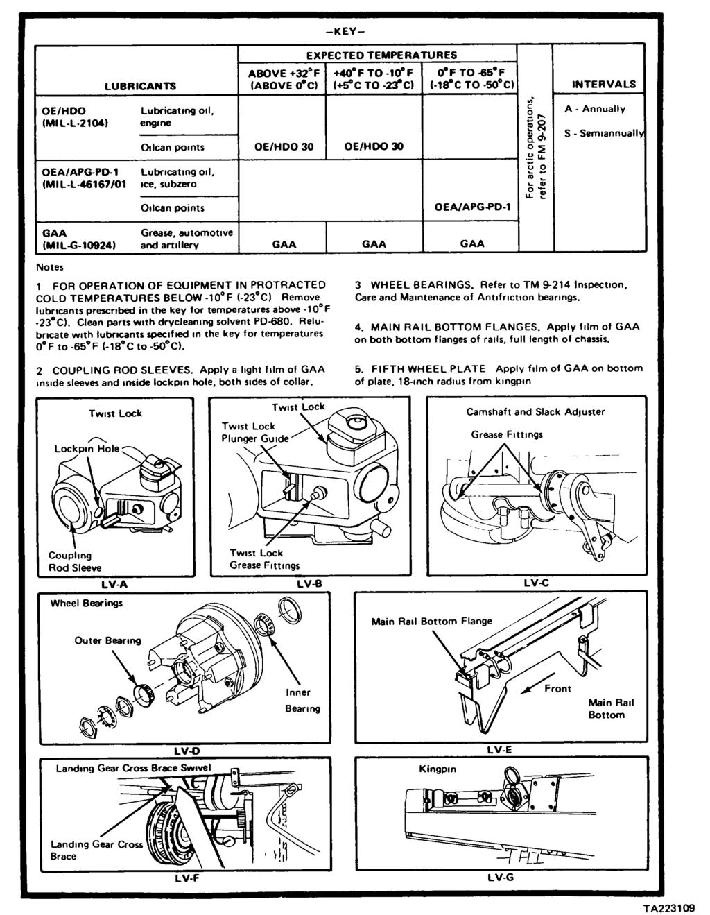
81 4-4 TM &P
82 Section II. REPAIR PARTS; SPECIAL TOOLS; TEST, MEASUREMENT, AND DIAGNOSTIC EQUIPMENT (TMDE); AND SUPPORT EQUIPMENT TM &P Page Common Tools and Equipment Repair Parts Page Special Tools, TMDE, and Support Equipment COMMON TOOLS AND EQUIPMENT Refer to the Modified Table of Organization and Equipment (MTOE) for authorized common tools and equipment applicable to your unit. SPECIAL TOOLS, TMDE, AND SUPPORT EQUIPMENT No special tools, TMDE, or support equipment are required to maintain the semitrailer. REPAIR PARTS Repair parts are listed and illustrated in appendix F of this manual. Section III. SERVICE UPON RECEIPT Page Preliminary Servicing and Adjustment of Equipment Page Service Upon Receipt of Materiel SERVICE UPON RECEIPT OF MATERIEL This task covers: Unpacking and Checking Unpacked Equipment INITIAL SETUP Tools Materials/Parts Nail puller Drycleaning solvent PD-680 (item 1, Strap cutter appendix E) Rags (item 2, appendix E) 4-5
83 SERVICE UPON RECEIPT OF MATERIEL - CONTINUED ACTION LOCATION ITEM REMARKS 1. Semitrailer DD Form 1397 Read and follow all instructions. 2. Metal strapping, Using strap cutters and nail pullers, replywood, tapes, move strappings, plywood, tapes, seals, seals, and and wrappings. wrappings WARNING Drycleaning solvent PD-680 is both toxic and flammable. Avoid prolonged breathing of vapors and avoid skin contact Do not use near open flame or excessive heat Flash point of solvent is 138 F (59 C). 3. Coated exterior Using drycleaning solvent and rags, remove parts rust preventive compound. 4. Semitrailer a. Inspect the equipment for damage incurred during shipment. b. If the equipment has been damaged, report the damage on SF Form 364, Report of Discrepancy. c. Check to see whether the equipment has been modified. 5. Equipment a. Check the equipment against the packing packing slip slip to see If the shipment is complete. b. Report all discrepancies in accordance with the instructions in DA PAM TASK ENDS HERE PRELIMINARY SERVICING AND ADJUSTMENT OF EQUIPMENT Perform the operators and organizational preventive maintenance checks and services (PMCS) as described on pages 2-6 thru 2-13 and 4-7. Lubricate all lubrication points as shown in the Lubrication Chart (page 4-3), regardless of interval. Schedule the next PMCS on DD Form 314, Preventive Maintenance Schedule and Record. Report all problems on DA Form 2407 if the deficiencies appear to involve unsatisfactory design. Perform a break-in road test of 25 miles (40 23 kilometers) at a maximum speed of 55 mph (88.5 km/h). Change 1 4-6
84 Section IV. ORGANIZATIONAL PREVENTIVE MAINTENANCE CHECKS AND SERVICES Page Page General PMCS Column Description Organizational Preventive Main- Special Instructions tenance Checks and Services GENERAL The semitrailer must be inspected systematically to ensure that it is ready for operation at all times. Inspection will allow defects to be discovered and corrected before they result in serious damage or failure. This section contains a tabulated list of preventive maintenance checks and services. All deficiencies and corrective actions taken will be recorded on DA Form Do your (S) PMCS once each 6 months. Do your (A) PMCS once each year. SPECIAL INSTRUCTIONS If something doesn't work, troubleshoot it with the instructions in this manual or notify your supervisor. Always do your PMCS in the same order, so it gets to be a habit. Once you've had practice, you will spot something wrong in a hurry. If anything looks wrong and you can't fix it, write it down on your DA Form If you find something seriously wrong, report it to direct support as soon as possible. WARNING Drycleaning solvent PD-680 is both toxic and flammable. Avoid prolonged breathing of vapors and avoid skin contact. Do not use near open flame or excessive heat. Flash point of solvent is F (59 0 C). NOTE When you are doing any PMCS or routine checks, keep in mind the warnings and cautions. 4-7
85 SPECIAL INSTRUCTIONS - CONTINUED Routine checks like those that are listed below are not listed in the PMCS checks. They are things that you should do anytime you see they must be done. If you find a routine check In your PMCS, it is because other operators reported problems with this item. Keep it Clean. Dirt, grease, oil, and debris only get In the way and may cover up a serious problem. Clean as you work and as needed. Use drycleaning solvent PD-680 to clean metal surfaces. Use soap and water when you clean rubber or plastic material Bolts, Nuts, and Screws Check that they are not loose, missing, bent, or broken. You can't try them all with a tool of course, but look for chipped paint, bare metal, or rust around bolt heads. Tighten any that you find loose. Welds. Look for loose or chipped paint, rust, or gaps where parts are welded together. If you find a bad weld, report It to direct support. Electric Wires and Connectors Look for cracked or broken insulation, bare wires, and loose or broken connectors Tighten loose connections and make sure the wires are in good condition. Hoses and Lines Look for wear, damage, and leaks Make sure clamps and fittings are tight If a leak comes from a loose fitting or connector, tighten it. If something is broken or worn out, either correct It or report it to direct support (refer to MAC). PMCS COLUMN DESCRIPTION Item No. - The order that PMCS should be performed, and also used as a source of item numbers for the TM number column on DA Form 2404, Equipment Inspection and Maintenance Worksheet when recording results of PMCS. Interval - Tells when each check should be performed. Item to be Inspected - Lists the checks to be performed. NOTE Perform operator/crew PMCS prior to or in conjunction with organizational PMCS if there is a delay between daily operation of the equipment and the organizational PMCS, or if the regular operator is not helping or taking part. 4-8
86 ORGANIZATIONAL PREVENTIVE MAINTENANCE CHECKS AND SERVICES S- Semiannually A - Annually INTERVAL ITEM TO BE INSPECTED ITEM PROCEDURE: CHECK FOR AND HAVE REPAIRED, FILLED NO. S A REPLACED, OR ADJUSTED AS NEEDED 1. BRAKE SYSTEM a. Inspect brake system components for wear and damage I b. Check brake lining thickness without removing the drum Replace brake lining if lining is worn to 29/64 Inch (11 mm) c. Check brake lining thickness with brakedrum removed Replace brake lining if lining is within Inch (0.762 mm) of rivet head d. Adjust slack adjuster See page LUBRICATION Perform chassis lubrication as described In section I, Lubrication Instructions Change TA508351
87 Section V. ORGANIZATIONAL TROUBLESHOOTING PROCEDURES Page Page Explanation of Columns Symptom Index General GENERAL This section lists the common malfunctions that you may find during the operation or maintenance of the semitrailer or components You should do the test or inspection and corrective action in the order listed. This manual cannot list all malfunctions that may occur, nor all test or inspections and corrective actions. If a malfunction is not listed or is not corrected by the corrective action column, notify your supervisor. EXPLANATION OF COLUMNS Malfunction. Visual or operational indication that something is wrong with your semitrailer. Test or Inspection. Procedure used to isolate the problem to a system or a component. Corrective Action. Procedure used to correct the problem. SYMPTOM INDEX This symptom index is provided as a quick way to get you to the troubleshooting procedure that will help you solve the problem you are having. ELECTRICAL SYSTEM Page All lamps fail to light One or more (but not all) lamps fail to light Dim or flickering lights BRAKE SYSTEM WHEELS Brakes will not release No brakes or weak brakes Excessively worn, scuffed, or cupped tires LANDING GEAR Difficulty in lowering or raising landing gear
88 NOTE Semitrailer must be hooked up to the towing vehicle when performing electrical or airbrake system tests. ORGANIZATIONAL TROUBLESHOOTING MALFUNCTION TEST OR INSPECTION CORRECTIVE ACTION 1. ALL LAMPS FAIL TO LIGHT. Step 1. Check towing vehicle circuit breakers and fuses. ELECTRICAL SYSTEM Reset circuit breaker and replace bad fuses. See towing vehicle technical manual. Step 2. Check for open circuit in intervehicular cable. Military towing vehicles Have an assistant apply brakes on towing vehicle. Using multimeter, check voltage between contact D and contacts B, E, and J of intervehicular cable plug (1). Multimeter should read 24 volts. Commercial towing vehicle Have an assistant apply brakes on towing vehicle. Using multimeter, check voltage between contact 1 and contacts 2, 3, 4, 5, and 6 of intervehicular cable plug (2). Multimeter should read 12 volts. If improper or no reading is obtained, troubleshoot towing vehicle as described in towing vehicle technical manual. 4-11
89 ORGANIZATIONAL TROUBLESHOOTING - CONTINUED MALFUNCTION TEST OR INSPECTION CORRECTIVE ACTION 1. ALL LAMPS FAIL TO LIGHT - CONTINUED. Step 3. Using multimeter, check that 12 volts are available at connector (1). If voltage is available, proceed with step 4. If voltage is not available, proceed with step 5. Step 4. Using multimeter, check that 12 volts are available at connector (2). If no voltage is available, check harness assembly for damage If harness is not damaged, proceed with step 5. Step 5. Check for good ground at intervehicular cable connector on front of semitrailer. Using a multimeter, check for continuity between contact D (24-volt connector) or contact 1 (12-volt connector) and any bare metal on semitrailer chassis. If no continuity or high resistance exists, remove connector and ground wire. Clean ground wire and contact surface. Reinstall ground wire and connector. If continuity is not obtained, replace connector TA223112
90 ORGANIZATIONAL TROUBLESHOOTING - CONTINUED TM &P MALFUNCTION TEST OR INSPECTION CORRECTIVE ACTION 2. ONE OR MORE (BUT NOT ALL) LAMPS FAIL TO LIGHT. Step 1. Check for loose or broken light assembly. Tighten loose light assembly. Replace broken light assembly. See page 4-27 for taillight. See page 4-25 for license plate light. See page 4-23 for marker lights. 4-13
91 ORGANIZATIONAL TROUBLESHOOTING - CONTINUED TM &P MALFUNCTION TEST OR INSPECTION CORRECTIVE ACTION 2. ONE OR MORE (BUT NOT ALL) LAMPS FAIL TO LIGHT - CONTINUED. Step 2. Check for burned-out lamps Replace burned-out lamps. Step 3. Check for corroded or broken lamp contact and sockets (1) and (2). If corroded, scrape and clean contacts and sockets. Step 4. Using multimeter, check voltage at electrical harness connector at the bad light. Voltage reading should be approximately 12 volts. Inspect and repair harness assembly. See page Step 5. Using multimeter, check for continuity across points (1) and (2) for marker lights (3) and (4), for license plate light, and points (5) and (6) for taillight. Replace light assembly if no continuity exists. See page 4-27 for taillight, page 4-25 for license plate light, and page 4-23 for marker lights. 4-14
92 ORGANIZATIONAL TROUBLESHOOTING - CONTINUED TM &P MALFUNCTION TEST OR INSPECTION CORRECTIVE ACTION 3. DIM OR FLICKERING LIGHTS. Step 1. Check for loose or bad ground. See malfunction 1, step 5. Step 2. Check for loose, dirty, or corroded contacts at: Intervehicular cable connector. Front and rear main harness connectors. Front and rear harness connectors. Affected light assembly connector. Affected light assembly lamp socket. 4. BRAKES WILL NOT RELEASE. Tighten loose and clean dirty or corroded contacts. Check operation of relay valve (1). BRAKE SYSTEM NOTE If brake system air pressure is below 60 psi (413.7 kpa), the relay valve will go into emergency bypass and apply brakes until system pressure increases to 60 psi (413.7 kpa). Have assistant apply brakes at towing vehicle; then release brakes. Brake chamber air pressure should vent through relay valve. Replace relay valve if air does not vent. See page
93 ORGANIZATIONAL TROUBLESHOOTING - CONTINUED TM &P MALFUNCTION TEST OR INSPECTION CORRECTIVE ACTION 5. NO BRAKES OR WEAK BRAKES. Step 1. Check brake air chamber (1) for leaks. Have an assistant apply the brakes in the towing vehicle while you listen for leaks at the brake air chamber (1). Replace leaking brake air chamber (1). See page Step 2. Check relay valve (1) operation. Have an assistant apply brakes at towing vehicle while watching for slack adjuster (2) for movement. Replace relay valve (1) if there is no movement at slack adjuster (2) or if movement is slow. See page
94 ORGANIZATIONAL TROUBLESHOOTING - CONTINUED TM &P MALFUNCTION TEST OR INSPECTION CORRECTIVE ACTION Step 3. Check brakes for excessive clearance Adjust brakes as described on page WHEELS 6. EXCESSIVELY WORN, SCUFFED, OR CUPPED TIRES. Step 1. Check axle for bent spindle. Notify direct support maintenance. Step 2. Check axle alignment. Aline axle. See page LANDING GEAR 7. DIFFICULTY IN LOWERING OR RAISING LANDING GEAR. Step 1. Check left-hand jackscrew and gearbox operation. Disconnect coupling (1) at cross-shaft (2). Turn crank handle (3). If handle (3) turns hard, continue with step 2. If handle (3) turns easy, right-hand jackscrew is-bad. Replace right-hand landing gear leg (4). See page
95 ORGANIZATIONAL TROUBLESHOOTING - CONTINUED TM &P MALFUNCTION TEST OR INSPECTION CORRECTIVE ACTION Step 2. Check gearbox operation. Using 9/16-inch wrench remove capscrews (5) and cap (6). Turn crank handle (3). If handle (3) turns easy, left-hand jackscrew is bad. Replace left-hand landing gear leg. See page If handle (3) turns hard, gearbox is bad. Replace gearbox. See page Section VI. CLEANING AND INSPECTION INSTRUCTIONS Page Page Cleaning Instructions Inspection Instructions CLEANING INSTRUCTIONS WARNING Improper cleaning methods and use of unauthorized cleaning liquids or solvents can injure personnel and damage equipment. Refer to TM and TM Cleaning instructions will be the same for the majority of parts and components that make up the semitrailer. TA
96 CLEANING INSTRUCTIONS - CONTINUED The importance of cleaning must be thoroughly understood by maintenance personnel Great care and effort are required in cleaning. Dirt and foreign material are a constant threat to satisfactory maintenance. The following should apply to all cleaning, inspection, repair, and assembly operations: 1. Clean all parts before inspection, after repair, and before assembly. 2. Keep hands free of any accumulation of grease which can collect dust, dirt, or grit. 3. After cleaning cover, wrap all parts to protect them from dust and dirt. Lightly oil parts that are subject to rust. STEAM CLEANING Protect all electrical equipment that can be damaged by the steam or moisture before steam cleaning the exterior of the semitrailer. Place disassembled parts in a suitable container to steam clean. After cleaning, dry and cover (or lightly oil) all parts subject to rust. CASTINGS, FORGINGS, AND MACHINED METAL PARTS WARNING Dry-cleaning solvent PD-680 is both toxic and flammable Avoid prolonged breathing of vapors and avoid skin contact Do not use near open flame or excessive heat Flash point of solvent is 1380F (590C). Clean inner and outer surfaces with dry-cleaning solvent. Remove grease and accumulated deposits with a stiff bristle brush WARNING Particles blown by compressed air are hazardous. Make certain the airstream is directed away from user and other personnel in the area. To prevent injury, user must wear safety eye goggles or face shield when using compressed air Blow out all tapped (threaded) holes with compressed air to remove dirt and cleaning fluids. ELECTRICAL CABLES, FLEXIBLE HOSE, AND OIL SEALS CAUTION Washing oil seals, electrical cables, and flexible hoses with dry-cleaning solvents or mineral spirits will cause serious damage or destroy the material. 4-19
97 CLEANING INSTRUCTIONS - CONTINUED BEARINGS NOTE Wash electrical cables and flexible hose with water and soap solution, and wipe dry. Oil seals are generally damaged during removal. Cleaning will not be necessary because new seals will be used on assembly. Refer to TM 9214 for instructions and procedures covering care and maintenance of antifriction bearings. INSPECTION INSTRUCTIONS All components and parts must be carefully checked to determine if: 1. They are serviceable for reuse. 2. They can be repaired. 3. They must be scrapped. DRILLED AND TAPPED (THREADED) HOLES Inspect for wear, distortion, cracks, or any other damage in or around holes Inspect threaded areas for wear, distortion (stretched), or evidence of cross-threading. Mark all damaged areas for repair or replacement. METAL LINES, FLEXIBLE LINES (HOSES), AND METAL FITTINGS Inspect metal lines for sharp kinks, cracks, bad bends, or bad dents. Inspect flexible lines for fraying, evidence of leakage, or loose metal fittings or connectors. GEARS Inspect gear teeth for wear, chips, or breakage. Inspect gear shafts for wear or grooving. BUSHINGS Inspect bushings for excessive wear, elongation, or grooving. 4-20
98 Section VII. ELECTRICAL SYSTEM MAINTENANCE Page Page Front Harness Marker Light General Marker Light Lamp and Lens License Plate Light Rear Harness License Plate Light Lamp and Resistors Lens Taillight Main Chassis Harness Taillight Lens and Lamp Main Chassis Harness Repair GENERAL This section provides instructions for organizational maintenance of the electrical system. The following initial setup information applies to all procedures. Resources required are not listed unless they apply to the procedure Personnel are listed only if the task requires more than one technician. If Personnel Required is not listed, one technician can do the task. The normal standard equipment condition to start a maintenance task is power off. Equipment condition is not listed unless some other condition is required. 4-21
99 MARKER LIGHT LAMP AND LENS This task covers: a. Removal (page 4-22) b. Installation (page 4-22) INITIAL SETUP Tools Materials/Parts Screwdriver, flat-tip Lamp ACTION LOCATION ITEM REMARKS REMOVAL 1. Marker light Lens (1) Using screwdriver, pry lens (1) off light base (2). 2. Lamp (3) a. Push lamp (3) into socket (4) and turn counterclockwise. b. Remove lamp (3). INSTALLATION 3. Lamp (3) Push lamp (3) into socket (4) and turn clockwise to secure. 4. Lens (1) Place lens (1) on light base (2) and push to snap into place. TASK ENDS HERE 4-22 TA223117
100 MARKER LIGHT This task covers: a. Removal (page 4-23) b. Installation (page 4-23) INITIAL SETUP Tools Screwdriver, flat-tip ACTION LOCATION ITEM REMARKS REMOVAL 1.Marker light Lens (1) Using screwdriver, pry lens (1) off light base (2). 2. Terminal (3), a. Pull terminal (3) from harness screws (4), light connector (6). base (2) and b. Using screwdriver, remove two gasket (5) screws (4). c. Remove light base (2) and gasket (5). INSTALLATION 3. Gasket (5), light a. Assemble parts base (2), screws b. Using screwdriver, tighten two (4) and terminal (3) screws (4). c. Push terminal (3) into harness connector (6). 4. Lens (1) Place lens (1) on light base (2) and push to snap it into place. 4-23
101 LICENSE PLATE LIGHT LAMP AND LENS This task covers: a. Removal (page 4-24) b. Installation (page 4-24) INITIAL SETUP Tools Screwdriver, flat-tip Materials/Parts Lamp ACTION LOCATION ITEM REMARKS REMOVAL 1.License plate Retaining ring a. Using screwdriver, pry off retaining light (1), lens (2), ring (1). gasket (3) and b. Remove lens (2) and gasket (3). lamp (4) c. Push lamp (4) into socket (5) and turn counterclockwise. d. Remove lamp (4). INSTALLATION 2. Lamp (4), gasket a. Push lamp (4) into socket (5) and turn (3), lens (2) clockwise to secure. and retaining b. Place gasket (3) and lens (2) on light ring (1) base (6) with frosted surface of lens (2) toward ground. c. Snap retaining ring (1) into groove of light base (6). 4-24
102 LICENSE PLATE LIGHT This task covers: a. Removal (page 4-25) b. Installation (page 4-25) INITIAL SETUP Tools Screwdriver, flat-tip ACTION LOCATION ITEM REMARKS REMOVAL 1. License plate Retaining ring (1), a. Using screwdriver, pry off retaining light lens (2), gasket ring (1). (3), screws (6) b. Remove lens (2) and gasket (3). and light base (7) c. Pull terminal (4) from harness connector (5). d. Using screwdriver, remove two screws (6) and light base (7). INSTALLATION 2. Light base (7), a. Position light base (7) on chassis screws (6), gasket frame. (3), lens (2) and b Using screwdriver, install two retaining ring (1) screws (6). c. Push terminal (4) into harness connector (5). d. Place gasket (3) and lens (2) on light base (7). e. Snap retaining ring (1) into groove of light base (7). 4-25
103 TAILLIGHT LENS AND LAMPS This task covers: a. Removal (page 4-26) b. Installation (page 4-26) INITIAL SETUP Tools Screwdriver, cross-tip Materials/Parts Lamps ACTION LOCATION ITEM REMARKS REMOVAL 1. Taillight Screws (1), lens a. Using screwdriver, remove four screws (2) and lamps (3) (1) and lens (2). b. Push two lamps (3) into sockets (4) and turn counterclockwise. c. Remove lamps (3). INSTALLATION 2 Lamps (3), lens a. Push two lamps (3) into sockets (4) and (2) and screws (1) turn clockwise to secure them. b. Place lens (2) in taillight (5). c. Using screwdriver, install four screws (1). 4-26
104 TM &P TAILLIGHT This task covers: a. Removal (page 4-27) b. Installation (page 4-27) INITIAL SETUP Tools Screwdriver, cross-tip ACTION LOCATION ITEM REMARKS REMOVAL 1.Taillight Harness Pull harness connector (1) from taillight connector (1) receptacle (2). 2. Screws (3) and Using screwdriver, remove four screws (3) taillight (4) and taillight (4). INSTALLATION 3. Taillight Taillight (4) and a. Position taillight (4) on taillight screws (3) frame (5). b. Using screwdriver, install four screws (3). 4. Harness Push harness connector (1) into taillight connector (1) receptacle (2). 4-27
105 MAIN CHASSIS HARNESS This task covers: a. Removal (page 4-28) b. Installation (page 4-30) INITIAL SETUP Tools Screwdriver, cross-tip Screwdriver, flat-tip Tool kit, electrical connector Materials/Parts Electrical tape Plastic sleeves ACTION LOCATION ITEM REMARKS REMOVAL 1. Semitrailer Rear harness Pull plug (1) from receptacle (2). Chassis plug (1) 2. Main harness a. Using screwdriver, remove screws (3). receptacle (2) b. Pull receptacle (2) from chassis and remove electrical tape covering receptacle to harness attach screws (4). c. Pull back plastic sleeves (5). d. Using screwdriver, loosen five screws (4). Remove wires (6). e. Remove receptacle (2). 4-28
106 MAIN CHASSIS HARNESS - CONTINUED ACTION LOCATION ITEM REMARKS 3. Semitrailer Main harness Pull plug (7) from receptacle (8) chassis plug (7) 4. Chassis front Grommet (9) and a Using screwdriver, pry grommet (9) from crossmember terminal (10) chassis crossmember b. Pull terminal (10) from three-way connector (11). 5. Semitrailer Main harness (12) a. Remove harness (12) from behind welded chassis clamp (13). b. Remove harness (12) from support clips (14). c. Using screwdriver, pry out grommet (15). d Pass harness (12) through hole (16) and remove harness from chassis. 4-29
107 MAIN CHASSIS HARNESS - CONTINUED ACTION LOCATION ITEM REMARKS INSTALLATION 6. Semitrailer Main harness (1) a. Pass harness (1) through hole (2). chassis b. Secure harness (1) with welded clamps (3). c. Support harness (1) on pipe (4) with support clips (5). d. Insert plug (6) in receptacle (7). e. Place grommet (8) around main harness (1) and work grommet (8) into hole (2). 7. Chassis front Terminal (9) and a. Push terminal (9) into three-way crossmember grommet (10) connector (11). b. Place grommet (10) around wire (12) and work grommet (10) into hole (13). TA
108 TM &P MAIN CHASSIS HARNESS - CONTINUED ACTION LOCATION ITEM REMARKS 8. Semitrailer Main harness a. Pass end of harness (20) through chassis receptacle (14) hole (15). b. Install plastic tubing (16) over five wires (17). c. Using wire strippers, strip 1/2 inch (12.7 millimeters) from ends of wires (17) and form end into a hook. d. Using screwdriver, secure wires (17) to their respective terminals, as shown in the figure below. e. Slide plastic sleeve (16) over terminals. f. Using electrical tape, wrap terminal end of receptacle (14). g. Place receptacle (14) on chassis. h. Using screwdriver, install screws (18). 9. Main harness Rear harness Push plug (19) into receptacle (14). receptacle (14) plug (19) TASK ENDS HERE TA
109 TM &P CHASSIS HARNESS REPAIR This task covers: Repair INITIAL SETUP Tools Pliers, diagonal cutting Tool kit, electrical connector Materials/Parts Tape, electrical Wire, 12-gage ACTION LOCATION ITEM REMARKS NOTE This task can be used to repair front, main, or rear chassis wiring harnesses. 1. Wire harness Wire harness (1) a. Remove 6 inches (15.24 centimeters) of break tape from wire harness (1). b Using pliers, stagger trim wires (2). c. Using wire stripper, strip ends of wires (2). 2. Five jumpers (3) a. Using wire stripper, strip both ends of jumper wires (3). b Using crimping tool, crimp one splice (4) on each end of jumper (3). c. Using crimping tool, install five jumpers (3) on matching wires (2). Check splices for good electrical and mechanical connection. d. Using electrical tape, wrap each splice and wire. Change
110 CHASSIS HARNESS REPAIR - CONTINUED ACTION LOCATION ITEM REMARKS e. Using electrical tape, wrap repaired wires together. Be sure new tape overlaps old tape. 3. Wire harness Wire loom (5) a. Using pliers, trim wire (5). b. Using wire strippers, strip end of wire (5) 4. Bullet Using crimping tool, install terminal (6). terminal (6) Check terminal for good electrical and mechanical connection. Change
111 CHASSIS HARNESS REPAIR - CONTINUED ACTION LOCATION ITEM REMARKS 5 Receptacle (7) a. Remove screw (8) b. Loosen two screws (9) c. Push harness and receptacle insert out of receptacle (7) d. Disconnect wires from receptacle (7) e. Connect wires to receptacle (7) f. Pull harness and receptacle Insert into receptacle (7) g. Tighten two screws (9) h. Install screw (8). TA E Change
112 CHASSIS HARNESS REPAIR - CONTINUED ACTION LOCATION ITEM REMARKS 6. Receptacle (10) a. Remove wires from receptacle (10) b. Install wires to receptacle (10) TASK ENDS HERE Change TA508353
113 RESISTORS This task covers: a. Removal (page 4-34) b. Installation (page 4-35) INITIAL SETUP Tools Screwdriver, flat-tip Soldering iron Wrench, box, 3/8-inch Materials/Parts Resistor Solder ACTION LOCATION ITEM REMARKS NOTE The following removal and installation procedure is for one resistor. Removal and installation of other resistors are similar. REMOVAL 1. Chassis front Resistor box (1) a. Using screwdriver, remove two crossmember screws (2). b. Pull resistor box (1) out of chassis front crossmember. 2. Resistor box (1) Resistors (3) a. Using soldering Iron, unsolder wires (4). b. Using screwdriver and 3/8-inch wrench, remove screws (5), nuts (6), and spacers (7) c. Unstack and remove bad resistor. Discard bad resistor. Change
114 RESISTORS - CONTINUED ACTION LOCATION ITEM REMARKS INSTALLATION 3. Resistors (3) a. Stack new resistor (3) on resistor box (1) using screws (5), spacers (7), and nuts (6). b. Using screwdriver and 318-inch box wrench, tighten screws (5). c. Using soldering iron, solder wires (4) to resistor (3). NOTE When installing 4-ohm resistors, be sure to solder jumper leads across their contacts. d. Using soldering iron, solder jumper lead (8) across resistor contact (9). 4. Chassis front Resistor box (1) a. Position resistor box (1) on chassis crossmember front crossmember. b. Using screwdriver, install screws (2). TASK ENDS HERE 4-35 TA223128
115 FRONT HARNESS This task covers: a. Removal (page 436) b. Installation (page 39) INITIAL SETUP Tools Screwdriver, flat-tip Soldering iron Tool kit, electrical connector Wrench, box, 3/8inch Materials/Parts Solder String Tape, electrical ACTION LOCATION ITEM REMARKS REMOVAL 1. Chassis front Resistor box (1) a. Using screwdriver, remove two crossmember screws (2). b. Pull resistor box (1) out of chassis front crossmember. 2. Resistor Receptacle a. Using soldering iron, unsolder three box (1) harness (3) wires (4) from resistor box (1). b. Tie a 4-foot (1.25meter) guide string on end of receptacle harness (3), and tie loose end to chassis. 4-36
116 FRONT HARNESS - CONTINUED ACTION LOCATION ITEM REMARKS 3. Chassis front Receptacle (5) a Using screwdriver, remove two crossmember screws (6) b. Pull receptacle (5) out of chassis front crossmember c. Using screwdriver, loosen screws (7) and unhook wires (8). d. Using screwdriver and 3/8-inch wrench, remove screw (9), nut (10), and ground wire (11) 4. Receptacle a Pull out of chassis through hole (12). harness (3) b. Untie and remove guide string from receptacle harness (3) Leave guide string attached to chassis. TA
117 TM &P FRONT HARNESS - CONTINUED ACTION LOCATION ITEM REMARKS REMOVAL - CONTINUED 4. Chassis side Receptacle (1) a. Pull main harness plug (2) out of rail receptacle (1). b. Using screwdriver, remove two screws (3). c. Pull receptacle (1) out of chassis side rail. d. Remove electrical tape covering screws (4). e. Pull plastic sleeves (5) off of screws (4). f. Using screwdriver, loosen five screws (4) and unhook wires (6). g. Tie a 4-foot (1.25meter) guide string (7) on end of wires (6). TA
118 TM &P FRONT HARNESS - CONTINUED ACTION LOCATION ITEM REMARKS 5. Front Grommet (8) a Using screwdriver, pry out. crossmember b. Remove from front harness (9). 6. Front harness (9) a. Remove from chassis through holes (11) and resistor box (10) and (12) b. Untie guide string from front harness (9). Leave string attached to chassis. INSTALLATION 7. Front Front harness (9) a Tie guide string to front harness (9) at crossmember and resistor box (10) end opposite resistor box (10). b. Using guide string, draw front harness (9) into chassis through holes (12) and (11) c. Remove guide string from front harness (9). TA
119 FRONT HARNESS - CONTINUED ACTION LOCATION ITEM REMARKS INSTALLATION - CONTINUED 8. Front Grommet (1) a. Install on front harness (2). Crossmember b. Using flat-tip screwdriver, install in hole (3). 9. Chassis side Receptacle (4) a. Using flat-tip screwdriver, connect rail wires of front harness (2) with screws (5) to their respective terminals by color code. b. Slide plastic sleeves (6) over terminals (7). c. Using electrical tape, wrap terminal end of receptacle (4). 10. Two screws (8) Using flat-tip screwdriver, secure receptacle (4). 11. Main harness plug (9) Push into receptacle (4). 12. Front Receptacle a. Tie guide string to receptacle harness crossmember harness (10) (10) on resistor box-attaching end. b. Using guide string, draw receptacle harness (10) into chassis through holes (11) and (12). 13. Resistor box (13) Using soldering iron, connect wires of receptacle harness (10) to their respective terminals by color code. 14. Two screws (14) Using flat-tip screwdriver, secure resistor box (13). 15. Receptacle (15) Using flat-tip screwdriver, connect wires of receptacle harness (10) with screws (16) to their respective terminals by color code. 4-40
120 FRONT HARNESS - CONTINUED ACTION LOCATION ITEM REMARKS 16. Front Screw (17), nut (18) Using flat-tip screwdriver and 3/8-inch crossmember and ground wire (19) open-end wrench, install on chassis. 17. Two screws (20) Using flat-tip screwdriver, secure receptacle (15) to chassis TASK ENDS HERE TA
121 TM &P REAR HARNESS This task covers: a. Removal (page 4-42) b. Installation (page 4-42) INITIAL SETUP Tools Screwdriver, flat-tip Materials/Parts String Tape, electrical ACTION LOCATION ITEM REMARKS REMOVAL 1. Rear chassis Rear harness (1) a. Pull connector (2) from main harness crossmember receptacle (3). b. Pull connectors (4) from taillight receptacle (5). c. Pull marker light connectors (6) from rear harness receptacles (7). d. Pull license plate light connector (8) from rear harness receptacle (9). e. Tie guide string to each connector. f. Using screwdriver, remove grommets (10), (11), (12), and (13). g. Pull rear harness (1) out of rear chassis crossmember through hole (14). h. Untie guide strings. INSTALLATION 2. Rear harness (1) a. Tie guide strings to harness (1). b. Draw new harness (1) through hole (14) and out of holes (15), (16), (17), and (18) c. Push connector (2) into receptacle (3). d. Push two connectors (4) into taillight receptacle (5). e. Push marker light connectors (6) into rear harness receptacles (7). f. Push license plate light connector (8) into rear receptacle (9). 4-42
122 REAR HARNESS - CONTINUED TASK ENDS HERE Section VIII. AXLE AND BOGIE ASSEMBLY MAINTENANCE Page Page Axle Bogie Locking Pins Bogie Assembly Bogie Position Pull Handle TA
123 AXLE This task covers: Alinement INITIAL SETUP Tools Materials/Parts Handle, reversible, 112-inch square Drycleaning solvent PD680 (item 1, drive appendix E) Rule, 6-inch machinist Masking tape (item 5, appendix E) Socket, 314-inch by 1/2-inch square Rags (item 2, appendix E) drive Tape measure, 20 feet long Personnel Required Wrench, open-end, 3/4-inch Wrench, torque Two ACTION LOCATION ITEM REMARKS WARNING Drycleaning solvent PD-680 is both toxic and flammable. Avoid prolonged breathing of vapor and avoid skin contact. Do not use near open flame or excessive heat. Flash point of solvent is 138 F (59 C). 1. Semitrailer Kingpin (1) Clean face of kingpin (1). 2. Kingpin (1) a. Apply masking tape to face of kingpin (1). b. Using 6-inch rule draw a line across face of kingpin (1) at its largest diameter. c. Turn rule 90 degrees and repeat step b. Lines drawn will cross at center of kingpin (1). 3. Semitrailer Kingpin (1) to a. Using tape measure, measure distance brakedrum (2) from center of kingpin (1) to nearest dimension point on machined surface of right brakedrum (2). Record distance as A. b. Repeat step a. for left wheel. Record distance as B. 4-44
124 AXLE - CONTINUED ACTION LOCATION ITEM REMARKS NOTE Dimensions A and B should be equal, however, allowable misalinement of left wheel to right wheel is zero inches forward, 1/8-inch toward rear of vehicle. 4. Axle Torque rod (3) a. Using 314-inch socket and 3/4-inch wrench, loosen nuts (4) and (5). b. Turn torque rod screw (6) until dimensions A and B are within limits. (See step 3.) c. Using 3/4-inch socket and 3/4-inch wrench, tighten nuts (4) and (5) d. Using torque wrench, torque nuts (4) and (5) to ft lb (61-75 N m). TASK ENDS HERE TA
125 BOGIE ASSEMBLY This task covers: a. Removal (page 4-46) b. Installation (page 4-48) INITIAL SETUP Tools Chain sling Jack stands (four each) Wrench, open-end, 9/161nch Materials/Parts Chock blocks (four each) ACTION LOCATION ITEM REMARKS REMOVAL 1. Chassis rear Rear bumper (1) Store rear bumper (1). See page Bogie (2) a. Place chocks (3) in front and back of wheels. b. Using jack stands (4), support bogie assembly (2). Place one jack stand in front and one in back. 3. Bogie (2) Airhoses (5) Uncouple airhoses (5) from semitrailer chassis fittings. 4. Pull handle Using 9/16-inch wrench, unscrew enough lock (6) to release pull handle (7). 5. Pull handle (7) Disengage pull handle (7), move downward and engage in lower slot to disengage bogie lockpins. b. Slide bogie (2) off chassis (8). 6. Semitrailer Chain sling (9) Attach sling (9) to chassis (8). chassis (8) Sling (9) Is to lift chassis (8) In a level and balanced condition. 4-46
126 BOGIE ASSEMBLY - CONTINUED ACTION LOCATION ITEM REMARKS 7. Semitrailer a. Using a suitable hoist, lift weight of chassis (8) chassis (8) off bogie (2). b. Slide bogie (2) off chassis (8) c. Place chassis (8) on jack stands (10). TA
 Pull handle (5) Pull pull handle (5) up and latch it in the bogie lockpin engage position. 10.")
127 BOGIE ASSEMBLY - CONTINUED ACTION LOCATION ITEM REMARKS INSTALLATION 8. Semitrailer a. Using suitable hoist, lift chassis (1) with chain sling (2). b. Remove jack stands (3). c. Slide chassis (1) onto bogie (4). 9. Bogie (4) Pull handle (5) Pull pull handle (5) up and latch it in the bogie lockpin engage position. 10. Pull handle Using 9/16-inch open-end wrench, turn lock (6) pull handle lock (6) screw against pull handle (5). 11. Semitrailer Airhoses (7) Couple airhoses (7) onto chassis fitting (8) chassis (1) on side rail. 12. Chain sling (2) Lower chassis (1) and remove chain sling (2). 13. Bogie (4) Jack stands (3) Remove. and blocks (9) 14. Semitrailer Rear bumper (10) Lower. chassis (1) See page TASK ENDS HERE 4-48 TA223137
128 BOGIE POSITION PULL HANDLE This task covers: a. Removal (page 4-49) b. Installation (page 4-49) INITIAL SETUP Tools Pliers, diagonal cutting Wrench, open-end, 9116-inch Materials/Parts Cotter pins ACTION LOCATION ITEM REMARKS 1. Bogie Pull handle (1) a. Using 9/16-inch wrench, unscrew lock (2) part way. b. Unhook spring (3) from pull handle (1). c. Using pliers, remove cotter pins (4) and washer (5). Discard cotter pins (4). d. Remove pull handle (1) INSTALLATION 2. Pull handle (1) a. Position pull handle (1) and install washer (5) and cotter pins (4). b. Using pliers, bend cotter pin (4) ends. c. Hook spring (3) to pull handle (1) d. Using 9/16-inch wrench, tighten lock (2) TASK ENDS HERE 4-49 TA223138
129 BOGIE LOCKING PINS This task covers: a. Removal (page 4-50) b. Installation (page 4-50) INITIAL SETUP Tools Hammer, ball-peen Pliers, diagonal cutting Punch, drive-pin, 1/4-inch Materials/Parts Cotter pin ACTION LOCATION ITEM REMARKS 1. Bogie Locking pin (1) a. Using hammer and punch, remove pin (2). b. Using pliers, remove pin (3) and discard. c. Pull pin (1) out of pin cage (4) Spring (5) and washers (6) stay in cage (4). INSTALLATION 2. Bogie Locking pin (1) a. Install spring (5) and washers (6) in cage (4). b. Insert locking pin (1) In cage (4), and insert cotter pin (3). c. Using pliers, bend ends of pin (3). d. Using hammer and punch, install pin (2). TASK ENDS HERE TA
130 Section IX. BRAKE SYSTEM MAINTENANCE Page Page Air Lines, Hoses, and Fittings Brakeshoes Air Reservoir Relay Valve - Service and Air Reservoir Draincock Emergency Brake Camshaft Service Brake Brake Camshaft Bushings Slack Adjuster Brake Chamber SERVICE BRAKE This task covers' a. Removal (page 4-52) c. Inspection (page 4-53) b. Cleaning (page 4-52) d. Installation (page 4-53) INITIAL SETUP Tools Equipment Condition Hammer, ball-peen Brakedrum removed (page 4-80). Pliers, brake repair Pliers, retaining ring Punch, drive-pin Screwdriver, flat-tip 4-51
131 SERVICE BRAKE - CONTINUED ACTION LOCATION ITEM REMARKS REMOVAL 1. Service brake Return spring (1) Using brake repair pliers, remove return spring (1). NOTE If pins (4) are stuck in spider (5), use a hammer and punch to drive them out. 2. Anchor pins (4) a. Using retaining ring pliers, remove retaining rings (2). b. Remove washers (3). c. Remove pins (4). d. Remove brakeshoes (6). 3. Cam rollers (7) Using flat-tip screwdriver, unhook roller retainer (8) and rollers (7). NOTE Do step 4 only if inspection shows anchor pin bushings need replacing. 4. Axle spider Anchor pin Using hammer and punch, drive out bushing (9) bushing (9). CLEANING 5. Service brakes Clean all parts in accordance with the instructions on page
132 SERVICE BRAKE - CONTINUED ACTION LOCATION ITEM REMARKS INSPECTION 6. Service brakes a. Inspect all parts in accordance with the instructions on page b Inspect brake linings for a minimum 1/8- inch (3.2 mm) thickness and a minimum 1/16-inch (1.6 mm) rivet head depth. INSTALLATION 7. Axle spider Bushing (9) Using mallet, tap bushing (9) into spider (5). 8. Service brakes Cam rollers (7) a Position rollers (7) on brakeshoes (6). b. Using flat-tip screwdriver, install retainer (8) 9. Brakeshoes (6) a. Position brakeshoes (6) on spider (5). b. Insert anchor pins (4) through brakeshoes (6) and spider (5). c. Using retaining ring pliers, install washers (3) and retaining rings (2). 10. Return spring (1) Using brake repair pliers, install return spring (1) TA223140
133 SERVICE BRAKE - CONTINUED NOTE FOLLOW-ON MAINTENANCE: 1. Install brakedrum (page 482). 2. Adjust brakeshoes (page 4-62). TASK ENDS HERE BRAKE CAMSHAFT This task covers: a. Removal (page 4-54) b. Installation (page 4-55) INITIAL SETUP Tools Equipment Condition Pliers, brake repair Spider and brakedrum removed (page 4-80). Slack adjuster removed (page 4-59). Materials/Parts Rags, (item 2, appendix E) Solvent, drycleaning, PD-680 (item 1, appendix E) ACTION LOCATION ITEM REMARKS REMOVAL WARNING Drycleaning solvent PD-80 is both toxic and flammable. Avoid prolonged breathing of vapors and avoid skin contact. Do not use near open flame or excessive heat. Flash point of solvent is 138 F (59 C). NOTE Procedures given are for one camshaft. 1. Axle Camshaft (1) a. Using rags and drycleaning solvent, clean camshaft (1) of all dirt and grease. 4-54
134 BRAKE CAMSHAFT - CONTINUED ACTION LOCATION ITEM REMARKS INSTALLATION b. Using brake repair pliers, remove spring (2). Allow lower brakeshoe (3) to swing down. c. Raise upper brakeshoe (4) and pull camshaft (1) out through spider (5). 2. Axle Camshaft (1) Raise upper brakeshoe (4) and slide camshaft (1) through spider (5) and camshaft support (6). Allow brakeshoe (4) to rest on camshaft (1). 3. Return spring (2) a. Hook spring (2) onto spring pin on upper brakeshoe (4) b. Raise lower brakeshoe (3) into position. c. Using brake repair pliers, install spring (2) on lower spring pin (7). TASK ENDS HERE 4-55 TA223141
135 BRAKE CAMSHAFT BUSHINGS This task covers: a. Removal (page 4-56) c. Inspection (page 4-57) b. Cleaning (page 4-57) d. Installation (page 4-58) INITIAL SETUP Tools Materials/Parts Hammer, ball-peen Packing Handle, reversible, 3/8-inch square drive Equipment Condition Mallet, soft-face Pliers, retaining ring Brake camshaft removed (page 4-54). Punch, straight, 3/4-inch Socket, 9/16- by 3/8-inch square drive Wrench, box, 9/16-inch ACTION LOCATION ITEM REMARKS REMOVAL 1. Camshaft sup- Camshaft a. Using 9/16-inch socket and 9/16-inch port bracket bushing (1) box wrench, remove nuts (2), washers (3), and capscrews (4). b. Remove bushing retainers (5) and (6) from support bracket (7) and separate. c. Remove bushing (1) and packings (8) and discard. 4-56
136 BRAKE CAMSHAFT BUSHINGS - CONTINUED ACTION LOCATION ITEM REMARKS 2. Axle beam Camshaft a. Using retaining ring pliers, remove spider bushing (1) retaining ring (2). b. Remove washers (3) and packings (4). c. Push plastic bushing (5) out of bushing (1) d. Using hammer and punch, drive bushing (1) out of spider (6). CLEANING 3. Axle beam spider Clean all parts In accordance with the and camshaft sup- instructions on page 4-19 port bracket and retainer assembly INSPECTION 4. Axle beam spider Inspect all parts in accordance with the and camshaft sup- instructions on page port bracket and Replace parts that are unserviceable. retainer assembly TA
137 BRAKE CAMSHAFT BUSHINGS - CONTINUED ACTION LOCATION ITEM REMARKS INSTALLATION 5. Axle beam Camshaft a. Using soft-face mallet, tap bushing spider bushing (1) (1) into spider (2). b Push plastic bushing (3) into bushing (1). c. Install packings (4) and washers (5) d. Using retaining ring pliers, install ring (6). 6. Camshaft sup- Camshaft a Assemble bushing (7), packings (8), port bracket bushing (7) and retainers (9) and (10) onto camshaft support bracket (11). b. Using 9/16-inch socket and 9/16-inch box wrench, install capscrews (12), washers (13), and nuts (14) TASK ENDS HERE NOTE FOLLOW-ON MAINTENANCE: Install brake camshaft (page 4-55). TA
138 SLACK ADJUSTER This task covers. a. Removal (page 4-59) b. Installation (page 4-60) c Adjustment (page 4-60) INITIAL SETUP Tools Hammer Jack Jack stand Pliers, diagonal cutting Pliers, retaining ring Tools - Continued Wrench, adjustable Wrench, open-end, 13/16-inch Materials/Parts Cotter pin ACTION LOCATION ITEM REMARKS REMOVAL WARNING Wear protective goggles when opening air reservoir draincock to prevent eye injury. Step away from airstream to prevent injuries NOTE Procedures given are for one slack adjuster 1. Air reservoir Draincock (1) Open draincock (1) and drain reservoir (2) completely. 4-59
139 SLACK ADJUSTER - CONTINUED ACTION LOCATION ITEM REMARKS REMOVAL - CONTINUED 2. Slack adjuster Cotter pin (1) a Using cutting pliers, remove and discard and pin (2) cotter pin (1). b. Remove pin (2). 3. Camshaft Retaining ring (3), a. Using retaining ring pliers, remove washer (4) and slack ring (3). adjuster (5) b. Using hammer, remove slack adjuster (5). INSTALLATION 4. Camshaft Slack adjuster (5), a. Place slack adjuster (5) and washer (4) washer (4) and on camshaft (6). retaining ring (3) b. Using retaining ring pliers, install ring (3). ADJUSTMENT NOTE Slack adjuster must be adjusted initially so that, In its free state, it makes an angle with the brake chamber rod of slightly more than 90 degrees 5. Slack adjuster Adjusting nut (7) Using an adjustable wrench, turn in the direction necessary to obtain a slack adjuster to brake chamber rod angle of slightly more than 90 degrees. 6. Brake chamber Clevis yoke (8) and a. Using inch open-end and adlocknut (9) justable wrenches, loosen locknut (9). b. Turn clevis yoke in the required direction so that it lines up with the hole in slack adjuster (5). c. Tighten locknut (9). 7. Pin (2) and new a. Install pin (2). cotter pin (1) b. Using cutting pliers, install cotter pin (1). 4-60
140 SLACK ADJUSTER - CONTINUED NOTE FOLLOW-ON MAINTENANCE: Adjust brakes (page 4-62) TASK ENDS HERE TA
141 BRAKESHOES This task covers. Adjustment INITIAL SETUP Tools Equipment Condition Feeler gage Semitrailer coupled to towing vehicle and Jack brake system charged (page 2-14). Jack stand Wheel bearings adjusted (page 4-83). Wrench, adjustable ACTION LOCATION ITEM REMARKS NOTE Do not adjust brakes when drums are hot. Procedures given are for one slack adjuster. 1. Axle Wheels (1) a. Using jack (2), raise until clear of ground. b. Support with jack stand (3) and remove jack (2). NOTE All measurements should be taken as close as possible to the center of the brake lining. 2. Brake linings (4) Using a in (1.34-mm) feeler gage, check measurement between brake linings (4) and brakedrum (5). 3. Adjusting nut (6) Using an adjustable wrench, turn adjusting nut in the direction required to obtain the required dimension 4-62
142 BRAKESHOES - CONTINUED ACTION LOCATION ITEM REMARKS NOTE Apply service brakes. The angle between the slack adjuster and the brake chamber rod should be slightly greater than 90 degrees. If angle is 90 degrees or less, adjust slack adjuster (page 4-59). 4. Axle Wheels (1) a. Using jack (2), raise and remove jack stand (3). b. Remove jack stand (3) and jack (2). TASK ENDS HERE 4-63 TA223147
143 RELAY VALVE - SERVICE AND EMERGENCY This task covers: a. Removal (page 4-64) b. Installation (page 4-64) INITIAL SETUP Tools Materials/Parts Wrench, open-end, 5/8-inch Compound, sealing (item 7, appendix E) Wrench, open-end, 7/8-inch Wrench, pipe Equipment Condition Air reservoir draincock opened. ACTION LOCATION ITEM REMARKS REMOVAL 1. Relay valve (1) Air lines (2) a. Using 5/8-inch wrench, remove lines (2) and (3) and air- and (3). hoses (4) and (5) b. Using 7/8-inch wrench, remove hoses (4) and (5). 2. Relay valve (1) Using pipe wrench, remove nipple (6) with relay valve (1). 3. Relay valve (1) Nipple (6) Using pipe wrench, remove nipple (6) from relay valve (1). INSTALLATION 4. Relay valve (1) Nipple (6) Using pipe wrench and sealing compound on threads of nipple (6), install nipple (6) into relay valve (1). 4-64
144 RELAY VALVE - SERVICE AND EMERGENCY - CONTINUED ACTION LOCATION ITEM REMARKS 5. Air Relay valve (1) Using pipe wrench and sealing compound on reservoir (7) and nipple (6) threads of nipple (6), install nipple (6) and relay valve (1) in air reservoir (7). 6. Relay valve (1) Airhoses (4) Using 7/8-inch wrench and sealing comand (5) pound on threads of hose end fittings, install hoses (4) and (5). 7. Air lines (2) Using 5/8-inch wrench and sealing comand (3) pound, install lines (2) and (3) NOTE FOLLOW-ON MAINTENANCE: 1. Close air reservoir draincock 2. Charge air system and check for leaks TASK ENDS HERE 4-65 TA223148
145 AIR RESERVOIR This task covers' a. Removal (page 4-66) b. Installation (page 4-66) INITIAL SETUP Tools Materials/Parts Extension, socket wrench, 6- by Compound, sealing (item 7, appendix E) 3/8-inch square drive Handle, ratchet, 3/8-inch square Equipment Condition drive Socket, 9/16- by 3/8-inch square Relay valve removed (page 4-64). drive Wrench, box, 9116inch Wrench, open-end, 9/16-inch ACTION LOCATION ITEM REMARKS REMOVAL 1. Bogie Air reservoir (1), a. Using 9/16-inch socket and 9/16-inch nuts (2), bolts (3), wrench, remove four nuts (2), four bolts lockwashers (4) and (3) and lockwashers (4). grommets (5) b. Remove reservoir (1) from mount bracket (6). c. Using screwdriver, pry out four grommets (5). INSTALLATION NOTE New reservoir is shipped with draincock wired onto reservoir. 2. Air Draincock (7) Install draincock (7) using 9/16-inch reservoir (1) wrench and sealing compound on threads of draincock (7). 3. Grommets (5) Work four grommets (5) into air reservoir mount flange. 4-66
146 AIR RESERVOIR - CONTINUED ACTION LOCATION ITEM REMARKS 4. Bogie Air reservoir (1), a Place reservoir on mount bracket (6). bolts (3), lock- b Using 9/16-inch socket and 9116-inch washers (4) and wrench, install four bolts (3), locknuts (2) washers (4), and nuts (2) NOTE FOLLOW-ON MAINTENANCE: Install relay valve - service and emergency (page 4-64) TASK ENDS HERE TA
147 BRAKE CHAMBER This task covers. a. Removal (page 4-68) c. Assembly (page 4-70) b Disassembly (page 4-68) d. Installation (page 4-70) INITIAL SETUP Tools Pliers, diagonal cutting Wrench, adjustable, 12-inch Wrench, open-end, 518-inch (two required) Wrench, open-end, 314-inch Wrench, open-end, 13/16-inch Wrench, open-end, 7/8-inch Materials/Parts New diaphragm Cotter pin (as required) Equipment Condition Air reservoir draincock opened. ACTION LOCATION ITEM REMARKS REMOVAL NOTE Procedures given are for one brake chamber. 1. Brake chamber Airhose (1) Using 314- and 7/8-inch open-end wrenches, remove hose (1) from brake chamber (2). 2. Slack adjuster Cotter pin (3) a. Using cutting pliers, remove and disand clevis pin (4) card cotter pin (3). b. Remove clevis pin (4). 3. Axle Brake chamber (2) a. Using 13/16-inch open-end wrench, remove two nuts (5) and two lockwashers (6). b. Remove brake chamber (2). DISASSEMBLY 4. Brake chamber Clevis yoke (7) a. Using inch open-end and adjustand jamnut (8) able wrenches, loosen jamnut (8). b. Remove clevis yoke (7) and jamnut (8). 4-48
148 BRAKE CHAMBER - CONTINUED ACTION LOCATION ITEM REMARKS WARNING Brake chamber housing is under spring pressure. Secure the brake chamber in a suitable vise before removing housing clamps to prevent injuries 5. Brake chamber Two housing a. Clamp brake chamber (2) in vise clamps (9) b. Using two 518-inch open-end wrenches, remove nut (10), washer (11), and capscrew (12) 6. Housings (13) and a. Carefully open vise to relieve spring (14), diaphragm (15), pressure and separate housings (13) rod (16), spring and (14) retainer (17) and b. Disassemble parts spring (18) Discard diaphragm (15). 4-69
149 BRAKE CHAMBER - CONTINUED ACTION LOCATION ITEM REMARKS ASSEMBLY 7. Brake chamber Housings (1) and a. Place spring retainer (5) on rod (4). (2), new diaphragm b. Place spring (6) and rod (4) so that (3), rod (4), spring large end rests against spring reretainer (5) and tainer (5). spring (6) c. Slide rod (4) through housing (2). d. Position diaphragm (3) in housing (1). e. Using vise, compress housing halves (1) and (2) together. 8. Two housing clamps Using two 518-inch open-end wrenches, (7), capscrew (8), assemble parts. lockwasher (9) and nut (10) 9. Jamnut (11) and Install on rod (4). clevis yoke (12) Do not tighten. INSTALLATION 10. Axle Brake chamber (13) a. Place brake chamber (13) on mounting bracket (14). b. Using 13/16-inch open-end wrench, install washers (15) and nuts (16) 11. Airhose (17) Install airhose (17)using 3/4- and 7/8-inch open-end wrenches. NOTE The brake chamber will be connected to the slack adjuster during the adjustment procedure. 4-70
150 BRAKE CHAMBER - CONTINUED NOTE FOLLOW-ON MAINTENANCE' 1. Adjust slack adjuster (page 4-59). 2. Adjust brakeshoes (page 4-62). TASK ENDS HERE AIR LINES, HOSES, AND FITTINGS This task covers: a. Removal (page 4-72) b. Installation (page 4-74) INITIAL SETUP Tools Materials/Parts Screwdriver, flat-tip Compound, sealing (Item 7, appendix E) Wrench, open-end, 5/8-inch Wrench, open-end, 7/8-inch Equipment Condition Wrench, open-end, 1-inch (2 each) Air reservoir draincock opened TA223151
151 AIR LINES, HOSES, AND FITTINGS - CONTINUED ACTION LOCATION ITEM REMARKS REMOVAL NOTE The procedures given are typical for all air lines and fittings. 1. Chassis side Air lines (1) a. Using 518-inch wrench, remove nuts (2) rail from fittings (3). b. Remove line (1) from chassis side rail (4). 2. Airhoses (5) a. Uncouple hoses (5) from quick disconnects (6) and (7). b. Using 7/8-inch wrench, remove hoses (5) from quick disconnect fittings (8) and (9). 3. Fittings (3), a. Using adjustable wrench, remove elbow quick disconnects fittings (3) from nuts (2). (6) and/or (7), b. Using a 1-inch wrench, remove quick jamnuts (10), disconnects (6) and/or (7). coupling (11) and c. Using two 1-inch wrenches, remove nipples (12) jam nut (10), coupling (11), and nipple (12). 4. Chassis front Gladhands (13), a. Using adjustable wrench, remove gladcrossmember jamnuts (14), hands (13) from nipple (15). nipple (15) and b. Using 1-inch wrench, remove nuts (13). reducer (16) c. Remove nipple (15) and reducer (16). 4-72
152 AIR LINES, HOSES,'AND FITTINGS - CONTINUED ACTION LOCATION ITEM REMARKS 5. Bogie Airhoses (17) a. Uncouple hoses (17) and (18). and (18) b. Using 718-inch wrench, remove airhoses (17) and (18) from coupling (11) 6. Air lines (19) a. Using 5/8-inch wrench, remove lines and (20), elbow (19) and (20) from elbow fittings (3). (3), jamnut (10) b. Using adjustable wrench, remove and coupling (11) elbow (3) from coupling (11) c. Using two 1-inch wrenches, remove nut (10) and coupling (11). 4-73
153 AIR LINES, HOSES, AND SITTINGS - CONTINUED ACTION LOCATION ITEM REMARKS REMOVAL - CONTINUED 7. Bogie Airhoses (1) Using 718-inch wrench, remove hoses (1) and (2) and (2) from relay valve (3) and brake chambers (4). INSTALLATION NOTE The procedures given are typical for all air lines and fittings. 8. Chassis side Couplings (1), a. Using two 1-inch wrenches, install rail jamnuts (2), coupling (1) and jamnut (2). nipples (3), b. Using 1-inch wrench and sealing comquick disconnects pound on threads, install nipples (3) (4) and (5) and and quick disconnects (4) and/or (5). fittings (6) c. Using an adjustable wrench and sealing compound on threads, install fittings (6). TA
154 AIR LINES, HOSES, AND FITTINGS - CONTINUED ACTION LOCATION ITEM REMARKS 9. Chassis front Nipples (7), jam- a. Using 1-inch wrench, install nipples crossmember nuts (8), reducer (7) and jamnuts (8). (9), fitting (10) b. Using an adjustable wrench and sealing and gladhands (11) compound on threads, install fitting (10) and reducer (9). c. Using an adjustable wrench and sealing compound on threads, install gladhands (11). 10. Bogie Coupling (1), a. Using two 1-inch wrenches, install jamnut (2), couplings (1) and jamnuts (2). fittings (12), b Using an adjustable wrench and sealing air lines (13) compound on threads, install and (14) and fittings (12) air lines (15) c. Using 5/8-inch wrench, install lines and (16) (13) and (14) d. Using 7/8-inch wrench, Install lines (15) and (16). e. Close reservoir draincock (17). 11. Airhoses (18) Using 718-inch wrench and sealing and (19) compound on threads, install hoses (18) and (19) and couple to quick disconnects (4) and (3). 4-75
155 AIR LINES, HOSES, AND FITTINGS - CONTINUED ACTION LOCATION ITEM REMARKS INSTALLATION - CONTINUED 12. Chassis side Air lines (1), a. Using 518-inch wrench, install lines rail grommets (2) and (1) onto fittings (5). quick disconnects b. Using screwdriver, install grommets (2) (3) and (4) around air lines (1) and work into chassis frame. c. Using 718inch wrench and sealing compound on threads, install quick disconnects (3) and (4). NOTE FOLLOW-ON MAINTENANCE: 1. Close air reservoir draincock. 2. Charge air system and check for leaks. TASK ENDS HERE TA
156 AIR RESERVOIR DRAINCOCK This task covers: a. Removal (page 4-77) b. Installation (page4-77) INITIAL SETUP Tools Wrench, open-end, 9/16-inch Equipment Condition Air reservoir draincock opened. Materials/Parts Compound, sealing (item 7, appendix E) ACTION LOCATION ITEM REMARKS REMOVAL 1. Air Draincock (2) Using 9/16-inch wrench, remove reservoir (1) draincock (1) INSTALLATION 2. Draincock (2) Using 9/16-inch wrench and sealing compound on threads, install draincock (2) on reservoir (1). NOTE FOLLOW-ON MAINTENANCE: Close air reservoir draincock, charge air system and check for leaks. TASK ENDS HERE 4-77 TA223156
157 Section X. WHEEL AND TIRE ASSEMBLY MAINTENANCE Page Page Rims and Tires Spider, Brakedrum, and Wheel Wheel Bearing Bearings RIMS AND TIRES This task covers: a. Removal (page 4-78) b. Installation (page 4-79) INITIAL SETUP Tools Handle, socket wrench, 3/4-inch square drive Hydraulic jack Jack stand Socket, 1 1/4- by 3/4-inch square drive Tools - Continued Torque wrench, ft lb, 314-inch square drive Two wheel chocks Personnel Required Two ACTION LOCATION ITEM REMARKS REMOVAL 1. Wheel assembly Wheel chocks (1) Chock wheels on opposite side of assembly being removed. 2. Stud nuts (2) Using 1 1/4-inch socket, loosen five nuts (2). Do not remove. 3. Axle beam Hydraulic jack a. Using jack (3), raise axle. (3) and jack b. Position jack stand (4) under axle stand (4) beam (5). 4. Wheel assembly Stud nuts (2) Using inch socket wrench, remove five and rim clamps (6) stud nuts (2) and rim clamps (6). 5. Rim and tire Spacer band (8) Remove. assemblies (7) NOTE For disassembly, repair, and reassembly of the tire, refer to TM Change
158 RIMS AND TIRES - CONTINUED ACTION LOCATION ITEM REMARKS 6. Wheel spider Two rim and tire Place on spider (9) with tire valves 180 assemblies (7) and degrees opposed. spacer band (8) INSTALLATION 7. Wheel assembly Five rim clamps (6) Place on spider (9) studs and tighten using and stud nuts (2) 1 1/4-inch socket wrench. 8. Hydraulic jack (3) a. Using jack (3), raise axle beam (5) off and jack stand (4) jack stand (4). b. Remove jack stand (4). c. Remove jack (3) after lowering axle beam (5). 9. Wheel assembly Stud nuts (2) a. Using 1 1/4-inch socket and torque wrench, torque five stud nuts (2) to ft lb ( N m). b. Remove wheel chocks (1). TASK ENDS HERE 4-79 TA223190
159 SPIDER, BRAKEDRUM, AND WHEEL BEARINGS This task covers: a. Removal (page 4-80) c. Assembly (page 4-82) b. Disassembly (page 4-81) d. Installation (page 4-82) INITIAL SETUP Tools Materials/Parts Hammer, ball-peen Grease, GAA (item 6, appendix E) Handle, reversible, 318-inch Grease seal square drive Drycleaning solvent PD-680 (item 1, Handle, socket wrench, 314-inch appendix E) square drive Rags (item 2, appendix E) Mallet, soft-face Puller kit Personnel Required Punch, straight, 3/4-inch Socket, 3 5/16- by 314-inch Two square drive Socket, 3 7/8- by 314-inch Equipment Condition square drive Socket, 1 1/8- by 314-inch Rims and tires removed (page 4-78). square drive Socket, 112- by 318-inch square drive References Torque wrench, ft lb, 3/4- inch square drive TM 9214, Inspection, Care, and Maintenance Wrench, box, inch of Antifriction Bearings ACTION LOCATION ITEM REMARKS REMOVAL 1. Wheel hub Hubcap (1), Using 112-inch socket, remove five screws screws (2), lock- (2) and take off lockwashers (3), hubcap washers (3) and (1), and gasket (4). gasket (4) 2. Axle, spindle Locknut (5) and Using 3 5/16-inch socket, remove locknut lockwasher (6) (5) and lockwasher (6). 4-80
160 SPIDER, BRAKEDRUM, AND WHEEL BEARINGS - CONTINUED ACTION LOCATION ITEM REMARKS 3. Adjusting nut a. Using inch socket, remove (7) and outer nut (7). bearing cone (8) b. Remove outer bearing cone (8). 4. Wheel hub (9) and Using an assistant, remove hub (9) and drum brakedrum (10) (10) from axle (11). DISASSEMBLY 5. Wheel hub Grease seal (12) a. Using puller kit, remove seal (12). and inner bearing Discard seal (12). cone (13) b. Remove bearing cone (13). 6. Inner and outer Using hammer and punch, remove bearing bearing cups cups (14) and (15). (14) and (15) 7. Wheel hub (9) and Using 1 1/8-inch socket and 1 1/8-inch brakedrum (10) wrench, remove nuts (16), washers (17), and capscrews (18). Hub (9) and drum (10) will separate. 4-81
161 SPIDER, BRAKEDRUM, AND WHEEL BEARINGS - CONTINUED ACTION LOCATION ITEM REMARKS ASSEMBLY 8. Wheel hub (1) and Using 1 18-inch socket, 1 1/-inch brakedrum (2) wrench, and torque wrench, install five capscrews (3), washers (4), and nuts (5). Torque nuts (5) to 295 ft lb (400 N m). 9. Bearing cups Using hammer and punch, install inner and (6) and (7) outer bearing cups (6) and (7) in wheel hub (1). 10. Inner bearing a. Lubricate bearing (8) with GAA grease cone (8) and and place in hub (1). (See TM ) grease seal (9) b. Using hammer, install grease seal (9). INSTALLATION 11. Axle Wheel hub (1) and Using an assistant, place hub (1) and drum brakedrum (2) (2) on axle (10). 12. Outer bearing a. Lubricate bearing (11) with GAA grease cone (11) and and place in hub (1). (See TM ) adjusting nut (12) b. Install adjusting nut (12) and adjust wheel bearings. See page Wheel hub Gasket (13), hub- Place gasket (13) and hubcap (14) on wheel cap (14), cap- hub (1). Install five capscrews, washers screws (15) and and, using 112-inch socket, tighten lockwashers (16) screws (15). NOTE FOLLOW-ON MAINTENANCE Install rims and tires (page 4-79) and adjust brakes (page 4-59). TASK ENDS HERE 4-82 TA223158
162 WHEEL BEARING This task covers: Adjustment INITIAL SETUP Tools Handle, socket wrench, 314-inch square drive Handle, reversible, 3/8-inch square drive Tools - Continued Jack, hydraulic Socket, by 3/4-inch square drive Socket, 3 7/8- by 3/4-inch square drive Socket, 112- by 318-inch square drive Torque wrench, ft lb, 3/4-inch square drive ACTION LOCATION ITEM REMARKS 1. Axle Hydraulic jack (1) Using jack (1), raise trailer. 2. Wheel hub Hubcap (2), cap- a. Using 1/2-inch socket, remove five screws (3), lock- capscrews (3), lockwashers (4), and washers (4) and hubcap (2). gasket (5) b. Remove gasket (5). Discard gasket (5). 3. Locknut (6) and Using 3 5/16-inch socket, remove nut (6) lockwasher (7) and lockwasher (7). Change
163 WHEEL BEARING - CONTINUED ACTION LOCATION ITEM REMARKS 4. Wheel hub Wheel bearings a. Using 3 7/8-lnch socket, loosen adjusting nut (1) b. Turn wheel assembly (2) Tighten adjusting nut (1) with 3 7/8-inch socket and torque wrench, against bearing shoulder on spindle. Torque adjusting nut to ft lb ( N m). This torque will automatically adjust new bearings to a range of tight to loose. c. Install lockwasher (3) on axle. d. Slide lockwasher (3) against adjusting nut (1) If dowel pin (4) does not enter hole in lockwasher (3), do step e. e. Remove lockwasher (3) Turn it over and reinstall. If dowel pin (4) does not enter hole in lockwasher (3), repeat steps a thru e. f. Using 3 5/16-inch socket and torque wrench, install locknut (5) and torque to ft lb ( N m) 5. Gasket (6), hubcap a Place gasket (6) and hubcap (7) on (7), lockwashers (8) wheel hub (10) and Install five lockand capscrews (9) washers (8) and capscrews (9) b. Using 1/2-inch socket, tighten cap-screws (9) 6. Axle Hydraulic jack (11) Lower and remove jack (11). TASK ENDS HERE Change TA223160
164 Section XI. LANDING GEAR MAINTENANCE Page Page Landing Gear Leg Landing Gear Gearbox LANDING GEAR LEG This task covers a. Removal (page 4-85) c. Assembly (page 4-88) b. Disassembly (page 4-87) d. Installation (page 4-88) INITIAL SETUP Tools Hammer, ball-peen Jack stands (two required) Punch, drive-pin, 1/4-inch tip Ratchet handle, socket-wrench, 1/2-inch square drive Socket, 9/16- by 1/2-inch square drive Tools - Continued Socket, 3/4- by 112-inch square drive Socket, 15/16- by 1/2-inch square drive Socket, 1 1/16- by 1/2-inch square drive Wrench, box-end, 9/16-inch Wrench, box-end, 3/4-inch Wrench, box-end, 15/16-inch ACTION LOCATION ITEM REMARKS REMOVAL 1. Left and right Four wheel Place in front and back of wheels (2). wheels chocks (1) 2. Semitrailer Jack stands (3) Using a hoist, raise chassis and place chassis stands (3) under chassis frame (4). 4-85
165 LANDING GEAR LEG - CONTINUED ACTION LOCATION ITEM REMARKS REMOVAL - CONTINUED NOTE This is a typical procedure for the left or the right side landing legs. 3. Landing gear Screws (1) and Using screwdriver, remove two screws (1), leg cover (2) cover (2), and plug (3). 4. Pinion gear Groove pin (4) Using hammer and punch, remove groove pin (4). 5. Landing gear Nut (5), spacer a. Using 15/16-inch socket and 15/16inch leg (6), bolt (7) wrench, remove nut (5), spacer (6), and support (8) and bolt (7). b. Allow support (8) to swing clear of leg. 6. Nut (9), bolt a. Using inch socket and 15/16-inch (10) and lateral wrench, remove nut (9) and bolt (10). support (11) b. Allow support (11) to swing clear of leg. 7. Chassis frame Landing gear a. Using 3/4-inch socket and 3/4-inch leg (12) wrench, remove nuts (13), washers (14), capscrews (15), and mounting bracket (16). b. Slide landing gear leg (12) and pinion gear (18) off cross-shaft (17). 8. Support (8) and a. Pull pin (19) out. pin (19) b. Remove support (8) 9. Lateral support (11), a. Using 15/16-inch socket and box-end bolt (20) and wrenches, remove nut (21) and nut (21) bolt (20). b. Remove lateral support (11). 4-86
166 LANDING GEAR LEG - CONTINUED ACTION LOCATION ITEM REMARKS DISASSEMBLY 10. Landing gear Sandshoe (22) a. Using 9/16-inch socket and 9116-inch leg box-end wrenches, remove nut (23) and capscrew (24). b. Remove axle (25), collar (26), and sandshoe (22). 4-87
167 LANDING GEAR LEG - CONTINUED ACTION LOCATION ITEM REMARKS DISASSEMBLY - CONTINUED 11. Landing gear Nut (1) and Using 1 1/16-inch socket, remove nut (1) leg washer (2) and washer (2). 12. Jackscrew (3) Bevel gear (4) Using puller, remove gear (4) and key (5). 13. Outer leg (6) Inner leg (7) Pull inner leg (7) out of outer leg (6). 14. Bearing (8) and Remove bearing (8) and washer (9) from washer (9) jackscrew (5). 15. Flange bearing (10) Remove flange bearing (10) from outer leg (6). ASSEMBLY 16. Landing gear Washer (2), bearing a. Place washer (2) and bearing (8) on leg (8), flange bearing jackscrew (3). (10), inner leg (7) b. Place flange bearing (10) in outer and outer leg (6) leg (6). c. Insert inner leg (7) in outer leg (6). 17. Bevel gear (4), a. Place bevel gear (4) on jackscrew (3), key (5), washer alining slots for key (5). (2) and nut (1) b. Using hammer and 1/4-inch punch, tap key (5) fully into slot. c. Using 1 1/16-inch socket, install washer (2) and nut (1). 18. Sandshoe (11) a. Position sandshoe (11) and insert axle (1 2). b. Place collars (13) on axle (12). c. Using 9116-inch socket and 916-inch wrench, install capscrew (14), and nut (15). INSTALLATION 19. Semitrailer Lateral support (16) a. Place lateral support (16) in position. chassis b. Using 9116-inch socket and box-end wrenches, install bolt (17) and nut (18) 4-88
168 LANDING GEAR LEG - CONTINUED ACTION LOCATION ITEM REMARKS 20. Semitrailer Support (19) and a. Place support (19) in position. chassis pin (20) b. Secure with pin (20). 4-89
169 LANDING GEAR LEG - CONTINUED ACTION LOCATION ITEM REMARKS INSTALLATION - CONTINUED 21. Chassis frame Landing gear a. Slide landing gear leg (1) on crossleg (1) and shaft (3) part way. pinion gear (2) b. Place pinion gear (2) on cross-shaft (3) and slide landing gear leg (1) onto cross-shaft (3). 22. Leg mounting Using 3/4-inch socket wrench, install bracket (4) bracket (4), capscrews (5), washers (6), and nuts (7). 23. Landing gear Support (8), bolt a. Position support (8) at leg (1). leg (9), spacer (10) b. Using 15/16-inch socket wrench, install and nut (11) bolt (9), spacer (10), and nut (11). 24. Lateral support a. Position support (12) at leg (1). (12), bolt (13) b. Using inch socket and wrench, and nut (14) install bolt (13) and nut (14). 25. Groove pin (15), a. Adjust legs the same length. pinion gear (2) b. Aline holes in cross-shaft (3) and and cover (16) pinion gear (2). c. Using hammer and punch, install groove pin (15). d. Pack gear cavity with GAA grease. e. Using screwdriver, secure cover (16) with screws (17). f. Using hammer, Install plug (18). 26. Landing gear Perform operational check. leg (1) a. Raise landing gear leg (1). See page b. Lower landing gear leg (1). See page Jack stands (19) a. Using landing gear legs (1), raise chassis frame off jack stands (19). b. Remove jack stands (19) 28. Left and right Wheel chocks (20) Remove four wheel chocks (20). wheels 4-90
170 LANDING GEAR LEG - CONTINUED LANDING GEAR GEARBOX This task covers: a. Removal (page 4-92) c. Assembly (page 4-94) b. Disassembly (page 4-94) d. Installation (page 4-95) 4-91 TA223164
171 LANDING GEAR GEARBOX - CONTINUED INITIAL SETUP Tools Tools - Continued Hammer, ball-peen Socket, 9/16- by 3/8-inch square drive Handle, reversible, 3/8-inch Socket, 314- by 3/8-inch square drive square drive Wrench, box, 9/16-inch Punch, drive-pin, straight Wrench, box, 3/4-inch 1/4-inch point Pliers, slipjoint Materials/Parts Screwdriver, cross-tip Screwdriver, flat-tip Grease, GAA (item 6, appendix E) ACTION LOCATION ITEM REMARKS REMOVAL 1. Left and right Four wheel Place in front and back of wheels (2). wheels chocks (1) 2. Jack stands (3) Using suitable hoist, raise chassis front and place jack stands (3) under chassis frame (4). 3. Gearbox Crank handle (5) a. Using 9/16-inch socket and 9/16-inch wrench, remove nut (6), washers (7), and bolt (8). b. Remove handle (5). 4-92
172 LANDING GEAR GEARBOX,- CONTINUED ACTION LOCATION ITEM REMARKS REMOVAL - CONTINUED 4. Connecting Nuts (9), washers Using 9/16-inch socket and wrench, remove shaft (10) and cap- four nuts (9), washers (10), and screws (11) capscrews (11). 5. Couplings (12) Slide two couplings (12) onto connecting and shaft (13) shaft (13) and remove shaft (13). 6. Left landing Screws (14), Using flat-tip screwdriver, remove two gear leg cover (15) and screws (14) and cover (15); pry off plug (16) plug (16). 7. Groove pin (17) Using hammer and punch, remove pin (17). 8. Gearbox (18) a. Using 3/4-inch socket and wrench, remove nuts (19), washers (20), and capscrews (21). b. Slide gearbox (18) out off leg (22) and remove pinion gear (23) from shaft (24). 4-93
173 LANDING GEAR GEARBOX - CONTINUED ACTION LOCATION ITEM REMARKS DISASSEMBLY 9. Gearbox Screws (1), Using cross-tip screwdriver, remove six washers (2) and screws (1) and washers (2) Separate covers (3) and (4) cover (3) from cover (4) 10. Gears (5) and (6), a. Pull gears (5) and (6) with shafts (7) and shafts (7) and (8) out of cover (4). and (8) b. Using pliers, remove detent clip (9). c. Using hammer and punch, remove groove pins (10) and (11). d. Remove gears (5) and (6) from shafts (7) and (8). ASSEMBLY 11. Gears (5) and (6) a. Slide gears (5) and (6) onto shafts (7) shafts (7) and (8), and (8). groove pins (10) b. Using hammer and punch, install pins and (11) and detent (10) and (11). clip (9) c. Using pliers, install detent clip (9) on shaft (8). 12. Shafts (7) and (8), a. Using GAA grease, lubricate gears (5) covers (3) and (4), and (6) and shafts (7) and (8). washers (2) and b. Slide shafts (7) and (8) through screws (1) cover (4). c. Place cover (4) on cover (3). d. Using cross-tip screwdriver, install washers (2) and screws (1). 4-94
174 TM &P LANDING GEAR GEARBOX - CONTINUED ACTION LOCATION ITEM REMARKS INSTALLATION 13. Left landing Gearbox (1) a. Slide shaft (2) through landing gear gear leg leg (3) and pinion gear (4). b. Using 3/4-inch socket and 314-inch wrench, install capscrews (5), washers (6), and nuts (7) 14. Groove pin (8) Using hammer and punch, install groove pin (8). 15. Cover (9) and Using flat-tip screwdriver, install cover screws (10) (9) and two screws (10). 16. Plug (11) Using hammer, install plug (11). 17. Connecting shaft a. Place connecting shaft (12) between (12), couplings gearbox (1) and right landing leg. (13), capscrews b. Slide couplings (13) over left and right (14), washers cross-shafts (2). (15) and nuts (16) c. Using 9/16-inch socket and 9/16-inch wrench, Install capscrews (14), washers (15), and nuts (16). 4-95
175 LANDING GEAR GEARBOX - CONTINUED ACTION LOCATION ITEM REMARKS INSTALLATION - CONTINUED 18. Gearbox Crank handle (3) a. Place handle (3) on cross-shaft (1). b. Using 9/16-inch socket and 9/16-inch wrench, install bolt (4), washers (5), and nut (6). 19. Landing gear Perform operational check. legs (2) a. Raise landing gear legs (2). See page b. Lower landing gear legs (2). See page Rear axle Jack stands a. Using landing gear legs (2), raise (7) and wheel chassis frame off jack stands (7). chocks (8) b. Remove jack stands (7). c. Remove wheel chocks (8). TASK ENDS HERE Section XII. TORQUE ARM MAINTENANCE Torque Arm Page 4-96 TA223169
 INITIAL SETUP Tools Handle, reversible, 314-inch square drive Socket, 1 1/2- by 3/4-inch square drive Tools - Continued Wrench, box, 1 1/2-inch Wrench, torque, 3/4-inch")
176 TORQUE ARM This task covers: a. Removal (page 4-97) b. Installation (page 4-97) INITIAL SETUP Tools Handle, reversible, 314-inch square drive Socket, 1 1/2- by 3/4-inch square drive Tools - Continued Wrench, box, 1 1/2-inch Wrench, torque, 3/4-inch square drive ACTION LOCATION ITEM REMARKS REMOVAL 1. Bogie Torque arm (1) a. Using inch socket and wrench, remove nuts (2), washers (3), and bolts (4). b. Remove torque arm (1). INSTALLATION 2. Bogie Torque arm (1) a. Position torque arm (1) b. Using 1 1/2-inch socket and box wrench, install bolts (4), washers (3), and nuts (2). c. Using torque wrench, torque nuts (2) to ft lb ( N m). d. Aline axle (page 4144). TASK ENDS HERE 4-97 TA223170
177 Section XIII. FRAME AND BODY MAINTENANCE Page Page Frame and Body Repair and... Splash Guard Maintenance Uplock Assembly Rear Bumper REAR BUMPER This task covers: a. Removal (page 4-99) b. Installation (page 4-99) INITIAL SETUP Personnel Required Two 4-98
178 REAR BUMPER - CONTINUED ACTION LOCATION ITEM REMARKS REMOVAL 1. Chassis rear Rear bumper (1) a. Lift bumper (1) off hooks (2) and swing up. b. Pull bumper (2) from rails (3). INSTALLATION 2. Chassis rear Rear bumper (1) a. Slide bumper (1) onto rails (3). b. Lift bumper (1) and hang on hooks (2). NOTE Repair of the rear bumper is limited to the welding of minor cracks. Refer to TM 9-237, Welding Theory and Application, Operator's Manual. TASK ENDS HERE 4-99 TA223171
179 SPLASH GUARD This task covers: a. Removal (page 4-100) b. Installation (page 4-100) INITIAL SETUP Tools Handle, reversible, 1/2-inch square drive Socket, 9/16- by 112-inch square drive Wrench, box, 9116-inch ACTION LOCATION ITEM REMARKS REMOVAL 1. Chassis rear Nuts (1), lock- Using 9/16-inch box wrench and 9/16-inch end, mounting washers (2), screws socket wrench, remove four nuts (1), bracket (3), retainer plate lockwashers (2), screws (3), retainer plate (4) and splash (4), and guard (5). guard (5) INSTALLATION 2. Chassis rear Nuts (1), lock- a. Assemble parts on mounting bracket (6). end, mounting washers (2), screws b. Using 9/16-inch box wrench and socket bracket (3), retainer plate wrench, tighten nuts (1). (4) and splash guard (5) TASK ENDS HERE 4-100
180 UPLOCK ASSEMBLY TM &P This task covers: a. Removal (page 4-101) b. Installation (page 4-101), INITIAL SETUP Tools Handle, reversible, 318-inch square drive Socket, 9/16- by 3/8-inch square drive Wrench, box, 9/16-inch ACTION LOCATION ITEM REMARKS REMOVAL 1. Chassis frame Uplock latch (1) a. Using 9/16-inch socket and 9/16-inch wrench, remove nut (2), washers (3), spring (4), and capscrew (5). b. Using 9116-inch socket, remove nuts (6), washers (7), and latch (1). INSTALLATION 2. Uplock latch (1) a. Using 9/16-inch socket, install latch (1), washers (7), and nuts (6). b. Using 9116-inch socket and 9/16-inch wrench, install capscrew (5), spring (4), washers (3), and nut (2). TASK ENDS HERE TA
181 FRAME AND BODY REPAIR AND MAINTENANCE Refer to TB , Tactical Wheeled Vehicle Repair of Frame, for the repair and maintenance of the semitrailer chassis frame. Section XIV. BODY ACCESSORY MAINTENANCE Page Page Reflectors Data Plates REFLECTOR This task covers: a. Removal (page 4-103) b. Installation (page 4-103) INITIAL SETUP Tools Screwdriver, flat-tip 4-102
182 REFLECTOR - CONTINUED ACTION LOCATION ITEM REMARKS REMOVAL 1. Chassis frame Screw (1) and Using screwdriver, remove screw (1) and reflector (2) reflector (2). INSTALLATION 2. Chassis frame Screw (1) and Using screwdriver, install reflector (2) reflector (2) and screw (1). TASK ENDS HERE TA
183 DATA PLATES This task covers: a. Removal (page 4-104) b. Installation (page 4-104) INITIAL SETUP Tools Drill, electric, portable, 114-inch jaw Drill, twist, 5132-inch Tools - Continued Hammer, ball-peen Punch, drive-pin, 3/16-inch ACTION LOCATION ITEM REMARKS 1. Chassis side Drivescrews (1) a. Using 5/32-inch drill, drill heads rail and data plate (2) off drivescrews (1). b. Using hammer and punch, drive out remainder of screws (1) and remove data plate (2). INSTALLATION 2. Chassis side Drivescrews (1) a. Position data plate (2). rail and data plate (2) b. Using hammer, drive in four drivescrews (1). TASK ENDS HERE TA
184 Section XV. PREPARATION FOR STORAGE AND SHIPMENT Page Page Inspection During Storage Preservation Packing, Shipment, and Storage PRESERVATION Unit commanders are responsible for the proper care of the semitrailers. When you receive a semitrailer already processed for domestic shipment, (as indicated on DD Form 1397),the semitrailer does not have to be reprocessed for storage unless corrosion and deterioration are found during the inspection upon receipt. List all discrepancies found, due to poor preservation, packaging, packing, marking, handling, loading, or storage, and for excessive preservation on an SF 364. Repairs that cannot be handled by the receiving unit are to have tags attached listing the repairs needed. Reports of these conditions will be submitted by the unit commander for action by an ordnance maintenance unit. Semitrailers that are to be prepared for administrative storage must be given a technical inspection and processed as described in TM (Administrative Storage of Equipment). Semitrailers may be placed in administrative storage for 90 days. The preferred type of storage for semitrailers is under cover in open sheds or warehouses whenever possible. NOTE Use TM , TM and TM as references for processing, storage, and shipment of material with the instructions contained in this section. INSPECTION DURING STORAGE A visual inspection is to be performed periodically on all semitrailers placed in storage. If corrosion is found, remove it. Clean, paint, and treat the area with the prescribed preservatives. NOTE Touchup painting will be in accordance with TM , Painting Instructions for Field Use When semitrailers are not issued or shipped to another unit upon expiration of administrative storage period, they must be reprocessed in accordance with TM Semitrailers that are to be shipped and will reach their destination within the administrative storage period do not have to be reprocessed when removed from storage. If inspection reveals corrosion, or anticipated in-transit weather conditions make it necessary, reprocess in accordance with TM
185 INSPECTION DURING STORAGE - CONTINUED Semitrailers that are to be placed in service are to be deprocessed in accordance with TM Inspect and service the semitrailer in accordance with section III (Service Upon Receipt of Materiel), page 4-5. Repair or replace all items tagged on inspection prior to preservation. PACKING, SHIPMENT, AND STORAGE PREPARATION FOR SHIPMENT Protect the semitrailer against corrosion and damage. All unpainted metal surfaces are to be protected during shipment. Oil or grease, listed In the lubrication chart may be used for this purpose. Oil and grease are good only for a few days and semitrailers protected with oil and grease are to be watched closely for corrosion. Select a preservative that will not harm the surface to which it is applied. Prepare the semitrailer for shipment by processing it in accordance with TM
186 CHAPTER 5 DIRECT SUPPORT AND GENERAL SUPPORT MAINTENANCE INSTRUCTIONS OVERVIEW This chapter contains Information covering repair parts; special tools; test, measurement, and diagnostic equipment (TMDE); support equipment; and direct support and general support maintenance instructions for the 12-ton semitrailer (MILVAN) coupleable chassis Section I Repair Parts; Special Tools; Test, Measurement, and Diagnostic Equipment (TMDE); and Support Equipment Section II Maintenance Procedures Section I. REPAIR PARTS; SPECIAL TOOLS; TEST, MEASUREMENT, AND DIAGNOSTIC EQUIPMENT (TMDE); AND SUPPORT EQUIPMENT Page Page Common Tools and Equipment Repair Parts Page Special Tools, TMDE, and Support Equipment COMMON TOOLS AND EQUIPMENT Refer to the Modified Table of Organization and Equipment (MTOE) for authorized common tools and equipment applicable to your unit. SPECIAL TOOLS, TMDE, AND SUPPORT EQUIPMENT No special tools, TMDE, or support equipment are required to maintain the semitrailer. REPAIR PARTS Repair parts are listed and illustrated in appendix F of this manual. I 5-1
187 Section II. MAINTENANCE PROCEDURES Page Page Axle General Bogie Assembly Kingpin Brakedrum Spring Leaf Brakeshoes Torque Arm Bushings Chassis Frame Twist Lock GENERAL This section provides instructions for direct support and general support maintenance of the 12-ton semitrailer (MILVAN) coupleable chassis. The following initial setup information applies to all procedures. Resources required are not listed unless they apply to the procedure. Personnel are listed only if the task requires more than one technician. If Personnel Required is not listed, one technician can do the task. The normal standard equipment condition to start a maintenance task is power off. Equipment condition is not listed unless some other condition is required. BOGIE ASSEMBLY Repair of the bogie assembly at direct support and general support maintenance is limited to welding of minor cracks. Refer to TM 9237, Welding, Theory and Application, Operator's Manual. 5-2
188 AXLE BEAM This task covers a. Removal (page 5-3) b. Installation (page 5-4) INITIAL SETUP Tools Materials/Parts Jack, hydraulic, hand Rags, wiping (item 2, appendix E) Jack stand (two required) Solvent, drycleaning, type PD-680 (item 1, Ratchet handle, socket, 314-inch appendix E) drive Rule, folding, 6-foot Personnel Required Socket, 1 5/16- by 314-inch square drive Two Socket, by 3/4-inch square drive Equipment Condition Wrench, torque, 3/4-inch drive Wrench, box, 1 1/2-inch Service brakes removed (page 4-52) Camshafts removed (page 4-54). Brake chambers removed (page 4-68). ACTION LOCATION ITEM REMARKS REMOVAL 1. Semitrailer Axle (1) a. Using jack (2), raise axle (1) clear of chassis two jack stands (3). b. Move jack stands to under rear crossmember (4). c. Lower jack (2) so that semitrailer rests on jack stands (3). 5-3
189 AXLE BEAM - CONTINUED ACTION LOCATION ITEM REMARKS 2. Bogie Nuts (1), washers a. Using hydraulic jack, support axle (2), bolts (3) and beam (5). torque arms (4) b. Using inch socket, remove two nuts (1), two washers (2), and two bolts (3). 3. Nuts (6), washers Using 1 5/16-inch socket, remove eight (7) and bottom nuts (6), eight washers (7), and two botplates (8) tom plates (8). 4. U-bolts (9), top a. Remove four U-bolts (9), two top plates (10) and plates (10) and two liners (11). liners (11) b. Using hydraulic jack, lower axle beam (5). c. Remove axle beam (5) out from under chassis. INSTALLATION 5. Bogie Axle beam (5), a. Position beam (7) under chassis. liners (11) and b. Using hydraulic jack, raise axle beam two top plates (10) (5) to springs (12). Center axle beam (5) to bogie. c. Place two liners (11) and two top plates (1D) on springs (12). TA
190 AXLE BEAM - CONTINUED ACTION LOCATION ITEM REMARKS 6. U-bolts (9), bottom a. Place four U-bolts (9) over top plates (13), washers plates (10). (14) and nuts (15) b. Position two bottom plates (13) and install eight washers (14) and eight nuts (15). c. Using 1 5/16-inch socket, tighten nuts (15). d. Using torque wrench, torque nuts (15) to ft lb ( N.m). 7. Torque arms (16), a. Position torque arms (16) and insert two bolts (17), washers bolts (17). (18) and nuts (19) b. Install two washers (18) and two nuts (19). c. Using 1 1/2-inch socket and 1 1/2- inch box wrench, tighten nuts (19). d. Using torque wrench, torque nuts (19) to ft lb ( N.m). NOTE FOLLOW-ON MAINTENANCE. 1. Aline axle (page 4-44). 2. Install brake chamber (page 4-68). 3 Install camshaft (page 4-55) 4 Install service brake (page 4-53). 5. Install spider and drum (page 4-82). TASK ENDS HERE Page 5-6 has been rescinded T TA Change 1 5-5/(5-6 blank)
191 BRAKEDRUM This task covers: a. Inspection (page 5-7) b. Repair (page 5-7) INITIAL SETUP Tools Equipment Condition Inside micrometer Brakedrum removed (page 4-80). Brake lathe ACTION LOCATION ITEM REMARKS REPAIR 1. Brakedrum (1) Using inside micrometer, check for out-ofround or tapered condition. Maximum out-of-round is Inch (0.254 millimeter), maximum taper Is inch ( millimeter). 2. Brakedrum (1) Using brake lathe, reface braking surface to remove all cracks, heat checking, and scoring. Remove a maximum of Inch (0.254 millimeter) per cut. Discard drums with edge cracks or If inside diameter exceeds inches (42.24 centimeters). TASK ENDS HERE TA
192 TORQUE ARM BUSHINGS This task covers: Replacement INITIAL SETUP Tools Equipment Condition Punch, drive-pin, inch Torque arm removed (page 4-99). Materials/Parts Bushings (two required) ACTION LOCATION ITEM REMARKS 1. Torque arm (1) Two sleeve Using arbor press and inch drivebushings (2) pin punch, press out sleeve bushings (2). Discard sleeve bushings. 2. Two sleeve Using arbor press and inch drivebushings (2) pin punch, press in new sleeve bushings (2). TASK ENDS HERE 5-8 TA223181
193 KINGPIN This task covers a. Removal (page 5-9) b. Installation (page 5-9) INITIAL SETUP Tools Acetylene torch Arc welder Portable grinder References TM 9-237, Welding Theory and Application, Operator's Manual Materials/Parts Bracket Kingpin ACTION LOCATION ITEM REMARKS 1. Semitrailer Bracket (1) and a. Using torch, cut welds securing chassis kingpin (2) bracket (1) and kingpin (2) and remove b. Using grinder, grind edges smooth INSTALLATION 2. Kingpin (2) and a. Place kingpin (2) 23 5/8-inches (60 bracket (1) centimeters) from front of main chassis beam (5) and weld to fifth wheel plate (4) b Weld bracket (2) to kingpin (1) on crossmember (3) 5-9
194 TWIST LOCK This task covers: a. Removal (page 5-10) b. Installation (page 5-10) INITIAL SETUP Tools Hammer, ball-peen, 2-pound Punch, drive-pin, 9/16-inch Materials/Parts Twist lock assembly ACTION LOCATION ITEM REMARKS 1. Twist lock Pin (1), twist a. Raise twist lock head (2) fully. housing lock head (2), b. Using hammer and punch, drive pin (1) insert (3) and out of twist lock head (2) and handle (4) handle (4). c. Pull twist lock head (2) off. d. Pull insert (3) from housing (5). e. Unscrew handle (4). INSTALLATION NOTE Lubricate insert, stem screw, and shaft before installing. See lubricating chart page 4-3 for grease specification. 2. Twist lock Handle(4), insert a. Screw handle (4) into housing (5). housing (3), twist lock b. Install insert (3) in housing (5) with head (2) and counter bore up. pin (1) c. Place twist lock head on stem of handle (4) and aline holes (6). NOTE Place pin (1) on dry ice or In freezer for 2 hours prior to installing. d. Place pin in hole (6). e. Using hammer and punch, drive pin (1) in fully. Pin should not protrude, twist lock head (2). 5-10
195 TWIST LOCK - CONTINUED TASK ENDS HERE CHASSIS FRAME Repair of the chassis frame will be accomplished in accordance with TB , Tactical Wheeled Vehicles: Repair of frames. SPRING LEAF This task covers: a. Removal (page 5-12) b. Installation (page 5-14) 5-11 TA223183
196 SPRING LEAF - CONTINUED INITIAL SETUP Tools Tools - Continued Adapter, socket wrench, 314-inch Wrench, torque, 112-inch square drive, male square drive by 112-inch ft lb female square drive Wrench, torque, 3/4-inch square drive, Hydraulic jack ft lb Jack stands (2 each) Ratchet, reversible, 3/4-inch Materials/Parts square drive Socket, socket wrench, inch Spring leaf by 314-inch square drive Socket, socket wrench, 1 5/16 by Personnel Required 3/4-inch square drive Wrench, box, 15/16-inch Two ACTION LOCATION ITEM REMARKS REMOVAL 1. Semitrailer Chocks (1), jack (2) a. Place chocks (1) under wheels. chassis and jack stands (3) b. Using jack, raise chassis (4). c. Place stands (1) at rear corners. d. Lower jack so jack stands hold weight of chassis off spring leaf (5) with wheels on ground. 2. Bogie Nuts (6), washers Using 15/16-inch socket and wrench, re- (7), screws (8) move nuts (6), washers (7), screws (8), and spacers (9) and spacers (9). 5-12
, washers Using 1 5/16-inch socket, remove four nuts (11) and bottom (10), four washers (11), and bottom plate (12) plate (12). 4. Two U-bolts (13), Remove.")
197 SPRING LEAF - CONTINUED ACTION LOCATION ITEM REMARKS 3. Axle beam Nuts (10), washers Using 1 5/16-inch socket, remove four nuts (11) and bottom (10), four washers (11), and bottom plate (12) plate (12). 4. Two U-bolts (13), Remove. top plate (14) and liner (15) 5. Spring leaf (5) Remove spring leaf (5) off hi-seat (16) Use assistant to lift spring leaf (5) TA223185
198 SPRING LEAF - CONTINUED ACTION LOCATION ITEM REMARKS INSTALLATION 6. Axle beam Spring leaf (1) Install. a. Place spring leaf (1) over hi-seat (2) with tapered end forward. Use assistant to lift spring leaf (1). b. Seat stud (3) in hole on hi-seat (2). 7. Axle beam Liner (4), top a. Place liner (4) and top plate (5) on plate (5) and spring leaf (1). U-bolts (6) b. Position two U-bolts (6) over top plate (5). 8. Bottom plate (7), a. Place bottom plate (7) under axle beam washers (8) and and aline U-bolts (6) through holes. nuts (9) b. Using 1 5/16-inch socket, install four washers (8) and four nuts (9). c. Using torque wrench, torque nuts (9) to ft lb ( N m)
199 5-14
, screws (11), stall two spacers (10), two screws (11), washers (12) and two washers (12), and two nuts (13). nuts (13) b.")
200 SPRING LEAF - CONTINUED ACTION LOCATION ITEM REMARKS 9. Bogie Guide spacers a. Using inch socket and wrench, in- (10), screws (11), stall two spacers (10), two screws (11), washers (12) and two washers (12), and two nuts (13). nuts (13) b. Using torque wrench, torque to ft lb ( N.m). 10. Semitrailer Jack stands (14) Remove. chassis a. Using hydraulic jack, raise trailer chassis (15) off of jack stands (14) b. Remove jack stands (14). c. Using hydraulic jack, lower trailer chassis (15) TASK ENDS HERE 5-15/(5-16 blank) TA223187
1 1/2-TON, 2-WHEEL, M332 PAGE B1 (NSN ) REPAIR PARTS AND SPECIAL TOOLS LIST PAGE F-1
 REPAIR PARTS AND SPECIAL TOOLS LIST PAGE F-1") TECHNICAL MANUAL OPERATOR'S, ORGANIZATIONAL, DIRECT SUPPORT, AND GENERAL SUPPORT MAINTENANCE (INCLUDING REPAIR PARTS AND SPECIAL TOOLS LIST) OPERATING INSTRUCTIONS PAGE 2-1 OPERATOR PMCS PAGE 2-4 OPERATOR
TECHNICAL MANUAL OPERATOR'S, ORGANIZATIONAL, DIRECT SUPPORT, AND GENERAL SUPPORT MAINTENANCE (INCLUDING REPAIR PARTS AND SPECIAL TOOLS LIST) OPERATING INSTRUCTIONS PAGE 2-1 OPERATOR PMCS PAGE 2-4 OPERATOR
TM &P TECHNICAL MANUAL
 TECHNICAL MANUAL TM 9-2330-376-14&P OPERATOR S, ORGANIZATIONAL, DIRECT SUPPORT AND GENERAL SUPPORT MAINTENANCE MANUAL (INCLUDING REPAIR PARTS AND SPECIAL TOOLS LISTS) FOR CHASSIS, TRAILER: 5-TON, 4-WHEEL,
TECHNICAL MANUAL CHASSIS, TRAILER: GENERAL PURPOSE, 3-1/2 TON, 2-WHEEL, M353 (NSN )
") TECHNICAL MANUAL OPERATOR S, ORGANIZATIONAL, DIRECT SUPPORT, AND GENERAL SUPPORT MAINTENANCE MANUAL (INCLUDING REPAIR PARTS AND SPECIAL TOOLS LISTS) FOR CHASSIS, TRAILER: GENERAL PURPOSE, 3-1/2 TON, 2-WHEEL,
TECHNICAL MANUAL OPERATOR S, ORGANIZATIONAL, DIRECT SUPPORT, AND GENERAL SUPPORT MAINTENANCE MANUAL (INCLUDING REPAIR PARTS AND SPECIAL TOOLS LISTS) FOR CHASSIS, TRAILER: GENERAL PURPOSE, 3-1/2 TON, 2-WHEEL,
TM &P TECHNICAL MANUAL
 TECHNICAL MANUAL OPERATOR S, ORGANIZATIONAL, DIRECT SUPPORT, AND GENERAL SUPPORT MAINTENANCE MANUAL (INCLUDING REPAIR PARTS AND SPECIAL TOOLS LISTS) FOR TM 9-2330-359-14&P SEMITRAILER, FLATBED: BREAKBULK/CONTAINER
DEPARTMENT OF THE ARMY TECHNICAL MANUAL OPERATOR S, UNIT, INTERMEDIATE DIRECT SUPPORT AND INTERMEDIATE GENERAL SUPPORT MAINTENANCE
 TM 9-2330-380-14 & P DEPARTMENT OF THE ARMY TECHNICAL MANUAL OPERATOR S, UNIT, INTERMEDIATE DIRECT SUPPORT AND INTERMEDIATE GENERAL SUPPORT MAINTENANCE (INCLUDING REPAIR PARTS AND SPECIAL TOOLS LISTS)
TECHNICAL MANUAL M149A2. This manual supersedes TM &P, dated February 1981, and all changes.
 TECHNICAL MANUAL TM 9-2330-267-14&P OPERATOR S, ORGANIZATIONAL, DIRECT SUPPORT, AND GENERAL SUPPORT MAINTENANCE MANUAL (INCLUDING REPAIR PARTS AND SPECIAL TOOLS LISTS) FOR TRAILER, TANK, WATER: 400 GALLON,
ARMY TM &P AIR FORCE TO 36A
 ARMY TM 9-2330-213-14&P AIR FORCE TO 36A11-1-461 TECHNICAL MANUAL OPERATOR S, UNIT, DIRECT SUPPORT, AND GENERAL SUPPORT MAINTENANCE MANUAL (INCLUDING REPAIR PARTS AND SPECIAL TOOLS LISTS) FOR TRAILER,
TECHNICAL MANUAL OPERATOR S, UNIT, DIRECT SUPPORT, AND GENERAL SUPPORT MAINTENANCE MANUAL FOR
 TECHNICAL MANUAL OPERATOR S, UNIT, DIRECT SUPPORT, AND GENERAL SUPPORT MAINTENANCE MANUAL FOR SEMITRAILER, TANK: 5000 GALLON, (POTABLE WATER DISPENSING) XM1098 (NSN 2330-01-330-2779) Approved for public
TECHNICAL MANUAL OPERATOR'S, UNIT, DIRECT SUPPORT, AND GENERAL SUPPORT MAINTENANCE MANUAL (INCLUDING REPAIR PARTS AND SPECIAL TOOLS LISTS) FOR
 FOR") TECHNICAL MANUAL OPERATOR'S, UNIT, DIRECT SUPPORT, AND GENERAL SUPPORT MAINTENANCE MANUAL (INCLUDING REPAIR PARTS AND SPECIAL TOOLS LISTS) Operating Instructions 2-1 FOR DISTRIBUTOR, WATER, SEMITRAILER
TECHNICAL MANUAL OPERATOR'S, UNIT, DIRECT SUPPORT, AND GENERAL SUPPORT MAINTENANCE MANUAL (INCLUDING REPAIR PARTS AND SPECIAL TOOLS LISTS) Operating Instructions 2-1 FOR DISTRIBUTOR, WATER, SEMITRAILER
OPERATOR S, UNIT, DIRECT SUPPORT AND GENERAL SUPPORTMAINTENANCE MANUAL INCLUDING REPAIR PARTS AND SPECIAL TOOLS LISTS FOR ( )
") OPERATOR S, UNIT, DIRECT SUPPORT AND GENERAL SUPPORTMAINTENANCE MANUAL INCLUDING REPAIR PARTS AND SPECIAL TOOLS LISTS FOR SEMITRAILER, TANK, FUEL, 7500 GALLON, (2330-01-275-7475) M1062 Fruehauf Corporation
OPERATOR S, UNIT, DIRECT SUPPORT AND GENERAL SUPPORTMAINTENANCE MANUAL INCLUDING REPAIR PARTS AND SPECIAL TOOLS LISTS FOR SEMITRAILER, TANK, FUEL, 7500 GALLON, (2330-01-275-7475) M1062 Fruehauf Corporation
TECHNICAL MANUAL OPERATOR S, ORGANIZATIONAL, DIRECT SUPPORT AND GENERAL SUPPORT MAINTENANCE MANUAL (INCLUDING REPAIR PARTS AND SPECIAL TOOLS LIST)
") TECHNICAL MANUAL OPERATOR S, ORGANIZATIONAL, DIRECT SUPPORT AND GENERAL SUPPORT MAINTENANCE MANUAL (INCLUDING REPAIR PARTS AND SPECIAL TOOLS LIST) SEMITRAILER, VAN: ELECTRONIC 10-TON, 4 WHEEL XM574 (2330-00-086-7406)
TECHNICAL MANUAL OPERATOR S, ORGANIZATIONAL, DIRECT SUPPORT AND GENERAL SUPPORT MAINTENANCE MANUAL (INCLUDING REPAIR PARTS AND SPECIAL TOOLS LIST) SEMITRAILER, VAN: ELECTRONIC 10-TON, 4 WHEEL XM574 (2330-00-086-7406)
ARMY TM MARINE CORPS TM 09295A-14/1 TECHNICAL MANUAL
 ARMY TM 9-2330-381-14 MARINE CORPS TM 09295A-14/1 TECHNICAL MANUAL OPERATOR'S, UNIT, DIRECT SUPPORT, AND GENERAL SUPPORT MAINTENANCE MANUAL FOR HEAVY EQUIPMENT TRANSPORTER SEMITRAILER 70 TON, M1000 NSN
SEMITRAILER, LOWBED: 12-TON, M270A1 (NSN )
") TECHNICAL MANUAL OPERATOR S, ORGANIZATIONAL, DIRECT SUPPORT, AND GENERAL SUPPORT MAINTENANCE (INCLUDING REPAIR PARTS AND SPECIAL TOOLS LISTS) SEMITRAILER, LOWBED: 12-TON, M270A1 (NSN 2330-00-289-7515)
TECHNICAL MANUAL OPERATOR S, ORGANIZATIONAL, DIRECT SUPPORT, AND GENERAL SUPPORT MAINTENANCE (INCLUDING REPAIR PARTS AND SPECIAL TOOLS LISTS) SEMITRAILER, LOWBED: 12-TON, M270A1 (NSN 2330-00-289-7515)
1 1/2-TON, 2-WHEEL, M332 PAGE B1 (NSN ) REPAIR PARTS AND SPECIAL TOOLS LIST PAGE F-1
 REPAIR PARTS AND SPECIAL TOOLS LIST PAGE F-1") TECHNICAL MANUAL OPERATOR'S, ORGANIZATIONAL, DIRECT SUPPORT, AND GENERAL SUPPORT MAINTENANCE (INCLUDING REPAIR PARTS AND SPECIAL TOOLS LIST) OPERATING INSTRUCTIONS PAGE 2-1 OPERATOR PMCS PAGE 2-4 OPERATOR
TECHNICAL MANUAL OPERATOR'S, ORGANIZATIONAL, DIRECT SUPPORT, AND GENERAL SUPPORT MAINTENANCE (INCLUDING REPAIR PARTS AND SPECIAL TOOLS LIST) OPERATING INSTRUCTIONS PAGE 2-1 OPERATOR PMCS PAGE 2-4 OPERATOR
OPERATOR'S MANUAL CARRIER, CARGO, TRACKED, 1 /2 TON, M973 SMALL UNIT SUPPORT VEHICLE (SUSV) (NSN )
 (NSN )") OPERATOR'S MANUAL TABLE OF CONTENTS PAGE i EQUIPMENT DESCRIPTION PAGE 1-1 OPERATING INSTRUCTIONS PAGE 2-1 PREVENTIVE MAINTENANCE PAGE 2-6 CARRIER, CARGO, TRACKED, 1 /2 TON, M973 SMALL UNIT SUPPORT VEHICLE
OPERATOR'S MANUAL TABLE OF CONTENTS PAGE i EQUIPMENT DESCRIPTION PAGE 1-1 OPERATING INSTRUCTIONS PAGE 2-1 PREVENTIVE MAINTENANCE PAGE 2-6 CARRIER, CARGO, TRACKED, 1 /2 TON, M973 SMALL UNIT SUPPORT VEHICLE
TM &P TRAILER, BOLSTER: 4-TON, 4-WHEEL, GENERAL PURPOSE M796 (NSN ) AND M796A1 (NSN )
 AND M796A1 (NSN )") TECHNICAL MANUAL OPERATOR S, ORGANIZATIONAL, DIRECT SUPPORT, AND GENERAL SUPPORT MAINTENANCE (INCLUDING REPAIR PARTS AND SPECIAL TOOLS LIST) TRAILER, BOLSTER: 4-TON, 4-WHEEL, GENERAL PURPOSE M796 (NSN
TECHNICAL MANUAL OPERATOR S, ORGANIZATIONAL, DIRECT SUPPORT, AND GENERAL SUPPORT MAINTENANCE (INCLUDING REPAIR PARTS AND SPECIAL TOOLS LIST) TRAILER, BOLSTER: 4-TON, 4-WHEEL, GENERAL PURPOSE M796 (NSN
TECHNICAL MANUAL ORGANIZATIONAL MAINTENANCE MANUAL VOLUME 1 OF 3
 TECHNICAL MANUAL ORGANIZATIONAL MAINTENANCE MANUAL VOLUME 1 OF 3 This copy is a reprint which includes current pages from Change 1. TRACTOR, WHEELED (DED) LOADER BACKHOE W/HYDRAULIC IMPACT TOOL AND WIHYDRAULIC
TECHNICAL MANUAL UNIT MAINTENANCE MANUAL FOR TRUCK, TRACTOR, LINE HAUL 52,000 GVWR, 6 X 4, M915A2 (NSN )
") TECHNICAL MANUAL TM 9-2320-363-20-1 VOLUME NO. 1 UNIT MAINTENANCE MANUAL FOR TRUCK, TRACTOR, LINE HAUL 52,000 GVWR, 6 X 4, M915A2 (NSN 2320-01-272-5029) I TABLE I HOW OF CONTENTS TO USE THIS MANUAL I iii
TECHNICAL MANUAL TM 9-2320-363-20-1 VOLUME NO. 1 UNIT MAINTENANCE MANUAL FOR TRUCK, TRACTOR, LINE HAUL 52,000 GVWR, 6 X 4, M915A2 (NSN 2320-01-272-5029) I TABLE I HOW OF CONTENTS TO USE THIS MANUAL I iii
TM &P TECHNICAL MANUAL
 TECHNICAL MANUAL OPERATOR S, ORGANIZATIONAL, DIRECT SUPPORT, AND GENERAL SUPPORT MAINTENANCE MANUAL (INCLUDING REPAIR PARTS AND SPECIAL TOOLS LISTS) FOR SEMITRAILER, TANK: FUEL, 5000 GALLON, 4 WHEEL, M131A4
THIS MANUAL SUPERSEDES TM DATED 30 MAY 1994, INCLUDING ALL CHANGES. TECHNICAL MANUAL
 THIS MANUAL SUPERSEDES TM 9-2330-385-14 DATED 30 MAY 1994, INCLUDING ALL CHANGES. TECHNICAL MANUAL OPERATOR S, UNIT, DIRECT SUPPORT AND GENERAL SUPPORT MAINTENANCE MANUAL INTRODUCTION 1-1 OPERATING INSTRUCTIONS
OPERATOR'S MANUAL FOR
 OPERATOR'S MANUAL FOR CRUSHER, JAW: DIESEL AND ELECTRIC DRIVEN, WHEEL MOUNTED, PNEUMATIC TIRES, 75 TON PER HOUR EAGLE CRUSHER MODEL 5157 AND 5157A (NSN 3820-00-783-7311) EAGLE CRUSHER MODEL 5157B (NSN
BULLDOZER, EARTH MOVING: TANK MOUNTING, M9 ( )
") TECHNICAL MANUAL OPERATOR, ORGANIZATIONAL, DIRECT SUPPORT, AND GENERAL SUPPORT MAINTENANCE MANUAL (INCLUDING REPAIR PARTS AND SPECIAL TOOLS LIST) FOR BULLDOZER, EARTH MOVING: TANK MOUNTING, M9 (2590-00-708-3563)
TECHNICAL MANUAL OPERATOR, ORGANIZATIONAL, DIRECT SUPPORT, AND GENERAL SUPPORT MAINTENANCE MANUAL (INCLUDING REPAIR PARTS AND SPECIAL TOOLS LIST) FOR BULLDOZER, EARTH MOVING: TANK MOUNTING, M9 (2590-00-708-3563)
TECHNICAL MANUAL OPERATOR'S, UNIT, DIRECT SUPPORT AND GENERAL SUPPORT MAINTENANCE MANUAL (INCLUDING REPAIR PARTS AND SPECIAL TOOLS LIST)
") TECHNICAL MANUAL OPERATOR'S, UNIT, DIRECT SUPPORT AND GENERAL SUPPORT MAINTENANCE MANUAL (INCLUDING REPAIR PARTS AND SPECIAL TOOLS LIST) INTRODUCTION 1-1 OPERATING INSTRUCTIONS 2-1 OPERATOR MAINTENANCE
TECHNICAL MANUAL OPERATOR'S, UNIT, DIRECT SUPPORT AND GENERAL SUPPORT MAINTENANCE MANUAL (INCLUDING REPAIR PARTS AND SPECIAL TOOLS LIST) INTRODUCTION 1-1 OPERATING INSTRUCTIONS 2-1 OPERATOR MAINTENANCE
OPERATOR'S MANUAL COMPONENT OF CRUSHING AND SCREENING PLANT: DIESEL AND ELECTRIC DRIVEN, WHEEL MOUNTED, 75 TON PER HOUR
 OPERATOR'S MANUAL FOR CRUSHER, ROLL: DIESEL AND ELECTRIC DRIVEN, WHEEL MOUNTED, PNEUMATIC TIRES, 75 TON PER HOUR EAGLE CRUSHER MODEL 5230B AND 5230C (NSN 3820-00-788-5999) EAGLE CRUSHER MODEL 5230D (NSN
TECHNICAL MANUAL OPERATOR S, ORGANIZATIONAL, DIRECT SUPPORT, AND GENERAL SUPPORT MAINTENANCE (INCLUDING REPAIR PARTS AND SPECIAL TOOLS LISTS)
") TECHNICAL MANUAL OPERATOR S, ORGANIZATIONAL, DIRECT SUPPORT, AND GENERAL SUPPORT MAINTENANCE (INCLUDING REPAIR PARTS AND SPECIAL TOOLS LISTS) SEMITRAILER, LOWBED: 40-TON CONSTRUCTION EQUIPMENT TRANSPORTER
TECHNICAL MANUAL OPERATOR S, ORGANIZATIONAL, DIRECT SUPPORT, AND GENERAL SUPPORT MAINTENANCE (INCLUDING REPAIR PARTS AND SPECIAL TOOLS LISTS) SEMITRAILER, LOWBED: 40-TON CONSTRUCTION EQUIPMENT TRANSPORTER
TRANSPORTABLE (NSN ) LIFT, M720 DOLLY SET, SHELTER, 3-TON TM &P/TO 36A
 LIFT, M720 DOLLY SET, SHELTER, 3-TON TM &P/TO 36A") OPERATOR, ORGANIZATIONAL, DIRECT SUPPORT, AND GENERAL SUPPORT MAINTENANCE MANUAL (INCLUDING REPAIR PARTS AND SPECIAL TOOLS LISTS) DOLLY SET, SHELTER, 3-TON LIFT, M720 TRANSPORTABLE (NSN 2330-00-912-4251)
OPERATOR, ORGANIZATIONAL, DIRECT SUPPORT, AND GENERAL SUPPORT MAINTENANCE MANUAL (INCLUDING REPAIR PARTS AND SPECIAL TOOLS LISTS) DOLLY SET, SHELTER, 3-TON LIFT, M720 TRANSPORTABLE (NSN 2330-00-912-4251)
TECHNICAL MANUAL. Operator's, Organizational and Direct Support Maintenance Manual (Including Repair Parts and Special Tools List) for
 for") TECHNICAL MANUAL Operator's, Organizational and Direct Support Maintenance Manual (Including Repair Parts and Special Tools List) for CONVERTER ASSEMBLY, VAPOR RECOVERY PART NUMBER F428A NSN 2590-01-090-7659
TECHNICAL MANUAL Operator's, Organizational and Direct Support Maintenance Manual (Including Repair Parts and Special Tools List) for CONVERTER ASSEMBLY, VAPOR RECOVERY PART NUMBER F428A NSN 2590-01-090-7659
TM TECHNICAL MANUAL UNIT, INTERMEDIATE DIRECT SUPPORT AND INTERMEDIATE GENERAL SUPPORT MAINTENANCE INSTRUCTIONS
 TECHNICAL MANUAL UNIT, INTERMEDIATE DIRECT SUPPORT AND INTERMEDIATE GENERAL SUPPORT MAINTENANCE INSTRUCTIONS MAIN REDUCTION GEAR FOR LANDING CRAFT UTILITY (LCU) NSN 1905-01-154-1191 INTRODUCTION 1-1 UNIT
TECHNICAL MANUAL ORGANIZATIONAL, DIRECT SUPPORT, AND GENERAL SUPPORT MAINTENANCE MANUAL WITH REPAIR PARTS AND SPECIAL TOOLS LIST
 TECHNICAL MANUAL ORGANIZATIONAL, DIRECT SUPPORT, AND GENERAL SUPPORT MAINTENANCE MANUAL WITH REPAIR PARTS AND SPECIAL TOOLS LIST BITUMINOUS DISTRIBUTOR BODY M918, MODEL D-63 NSN 3895-01-028-4390 E.D. ETNYRE
TM T.O. 36A12-1B
 T.O. 36A12-1B-1092-1-3 TECHNICAL MANUAL Chapter 13 VOLUME 3 OF 3 PART 2 OF 4 MAINTENANCE ORGANIZATIONAL LEVEL 2½-TON, 6x6, M44A1 AND M44A2 SERIES TRUCKS (MULTIFUEL) Chapter 14 Chapter 15 Chapter 16 TRUCK,
This manual supersedes TM &P, dated 17 December 1987, and LO , dated 12 June 1986.
 TECHNICAL MANUAL OPERATOR'S, ORGANIZATIONAL, DIRECT SUPPORT, AND GENERAL SUPPORT MAINTENANCE MANUAL (INCLUDING REPAIR PARTS AND SPECIAL TOOLS LISTS) FOR SEMITRAILER, FLATBED: RADAR SET AND LAUNCHING STATION
TECHNICAL MANUAL ORGANIZATIONAL MAINTENANCE MANUAL VOLUME 2 OF 2
 TECHNICAL MANUAL ORGANIZATIONAL MAINTENANCE MANUAL VOLUME 2 OF 2 ORGANIZATIONAL MAINTENANCE INSTRUCTIONS - CONTINUED PAGE 2-664 MAINTENANCE ALLOCATION CHART (MAC) PAGE B-1 INDEX PAGE Index-1 TRUCK, DUMP,
SEMITRAILER, VAN: ELECTRONIC, 6-TON, 2-WHEEL
 TECHNICAL MANUAL UNIT, DIRECT SUPPORT AND GENERAL SUPPORT MAINTENANCE REPAIR PARTS AND SPECIAL TOOLS LISTS SEMITRAILER, VAN: ELECTRONIC, 6-TON, 2-WHEEL M348A2 M348A2C M348A2D M348A2F M348A2G M348A2H M348A2K
TECHNICAL MANUAL OPERATOR, AVIATION UNIT, AND AVIATION INTERMEDIATE MAINTENANCE MANUAL WITH REPAIR PARTS AND SPECIAL TOOLS LIST CHAPTER 1 INTRODUCTION
 EXTENDED RANGE FUEL SYSTEM ARMY MODEL CH-47 HELICOPTER TECHNICAL MANUAL OPERATOR, AVIATION UNIT, AND AVIATION INTERMEDIATE MAINTENANCE MANUAL WITH REPAIR PARTS AND SPECIAL TOOLS LIST CHAPTER 1 INTRODUCTION
TECHNICAL MANUAL OPERATOR'S, ORGANIZATIONAL, DIRECT SUPPORT, and GENERAL SUPPORT MAINTENANCE MANUAL (INCLUDING REPAIR PARTS AND SPECIAL TOOLS LIST)
") TM 5-4210-229-14&P TECHNICAL MANUAL OPERATOR'S, ORGANIZATIONAL, DIRECT SUPPORT, and GENERAL SUPPORT MAINTENANCE MANUAL (INCLUDING REPAIR PARTS AND SPECIAL TOOLS LIST) for TWIN AGENT 4x4 FIREFIGHTING TRUCK
TM 5-4210-229-14&P TECHNICAL MANUAL OPERATOR'S, ORGANIZATIONAL, DIRECT SUPPORT, and GENERAL SUPPORT MAINTENANCE MANUAL (INCLUDING REPAIR PARTS AND SPECIAL TOOLS LIST) for TWIN AGENT 4x4 FIREFIGHTING TRUCK
TM HEADQUARTERS, DEPARTMENT OF THE ARMY
 TM 9-2320-270-20-3 HEADQUARTERS, DEPARTMENT OF THE ARMY JUNE 1986 * TECHNICAL MANUAL HEADQUARTERS DEPARTMENT 0F THE ARMY NO. 9-2320-270-20-3 WASHINGTON, DC 10 JUNE 1986 ORGANIZATIONAL MAINTENANCE MANUAL
TECHNICAL MANUAL OPERATOR S, UNIT, DIRECT SUPPORT, AND GENERAL SUPPORT MAINTENANCE MANUAL (INCLUDING REPAIR PARTS AND SPECIAL TOOLS LISTS) FOR
 FOR") TECHNICAL MANUAL TM 9-2330-390-14&P OPERATOR S, UNIT, DIRECT SUPPORT, AND GENERAL SUPPORT MAINTENANCE MANUAL (INCLUDING REPAIR PARTS AND SPECIAL TOOLS LISTS) FOR DOLLY SET: LIFT, TRANSPORTABLE SHELTER,
TECHNICAL MANUAL TM 9-2330-390-14&P OPERATOR S, UNIT, DIRECT SUPPORT, AND GENERAL SUPPORT MAINTENANCE MANUAL (INCLUDING REPAIR PARTS AND SPECIAL TOOLS LISTS) FOR DOLLY SET: LIFT, TRANSPORTABLE SHELTER,
TM T.O. 36A12-1B MAINTENANCE 2½-TON 6X6, M44A1 AND M44A2 SERIES TRUCKS (MULTIFUEL) TRUCK, CARGO: M35A1,
 TRUCK, CARGO: M35A1,") T.O. 36A12-1B-1092-2-2 TECHNICAL MANUAL VOLUME 2 OF 2 PART 1 OF 3 MAINTENANCE DIRECT SUPPORT AND GENERAL SUPPORT LEVEL 2½-TON 6X6, M44A1 AND M44A2 SERIES TRUCKS (MULTIFUEL) TRUCK, CARGO: M35A1, M35A2,
T.O. 36A12-1B-1092-2-2 TECHNICAL MANUAL VOLUME 2 OF 2 PART 1 OF 3 MAINTENANCE DIRECT SUPPORT AND GENERAL SUPPORT LEVEL 2½-TON 6X6, M44A1 AND M44A2 SERIES TRUCKS (MULTIFUEL) TRUCK, CARGO: M35A1, M35A2,
TECHNICAL MANUAL OPERATOR'S, ORGANIZATIONAL, DIRECT SUPPORT AND GENERAL SUPPORT MAINTENANCE MANUAL
 TECHNICAL MANUAL OPERATOR'S, ORGANIZATIONAL, DIRECT SUPPORT AND GENERAL SUPPORT MAINTENANCE MANUAL COMPRESSOR, ROTARY; AIR, SKID MOUNTED; DIESEL ENGINE DRIVEN, 125 CFM, 100 PSIG (DAVEY MODEL 6M125) NSN
M48A5 TANK CHASSIS, TRANSPORTING: FOR BRIDGE, ARMORED-VEHICLE-LAUNCHED SCISSORING TYPE,CLASS 60 (NSN )
") TECHNICAL MANUAL ORGANIZATIONAL MAINTENANCE This copy is a reprint which includes current pages from Changes 1 through 3. M48A5 TANK CHASSIS, TRANSPORTING: FOR BRIDGE, ARMORED-VEHICLE-LAUNCHED SCISSORING
TECHNICAL MANUAL ORGANIZATIONAL MAINTENANCE This copy is a reprint which includes current pages from Changes 1 through 3. M48A5 TANK CHASSIS, TRANSPORTING: FOR BRIDGE, ARMORED-VEHICLE-LAUNCHED SCISSORING
ARMY TM P MARINE CORPS TM 09295A-24P/2 TECHNICAL MANUAL
 ARMY TM 9-2330-381-24P MARINE CORPS TM 09295A-24P/2 TECHNICAL MANUAL UNIT, DIRECT SUPPORT, AND GENERAL SUPPORT MAINTENANCE REPAIR PARTS AND SPECIAL TOOLS LIST FOR HEAVY EQUIPMENT TRANSPORTER SEMITRAILER
TM HEADQUARTERS DEPARTMENT OF THE ARMY
 TRUCK TRACTOR. LINE HAUL, 50,000 GVWR, 6 X 4, M95 (NSN 0-0-08-495) TRUCK TRACTOR, LIGHT EQUIPMENT TRANSPORTER (LET), 56,000 GVWR, 6 X 6, W/WINCH, M96 (NSN 0-0-08-496) TRUCK TRACTOR, MEDIUM EQUIPMENT TRANSPORTER
TECHNICAL MANUAL UNIT, DIRECT SUPPORT, AND GENERAL SUPPORT MAINTENANCE REPAIR PARTS AND SPECIAL TOOLS LISTS FOR
 TECHNICAL MANUAL UNIT, DIRECT SUPPORT, AND GENERAL SUPPORT MAINTENANCE REPAIR PARTS AND SPECIAL TOOLS LISTS FOR BULK HAUL, SELF LOAD/UNLOAD M967 (NSN 2330-01 -050-5632) AND M967A1 (NSN 2330-01-1 55-0046)
TECHNICAL MANUAL OPERATOR'S, UNIT, DIRECT SUPPORT, AND GENERAL SUPPORT MAINTENANCE (INCLUDING REPAIR PARTS AND SPECIAL TOOLS LIST)
") TECHNICAL MANUAL OPERATOR'S, UNIT, DIRECT SUPPORT, AND GENERAL SUPPORT MAINTENANCE (INCLUDING REPAIR PARTS AND SPECIAL TOOLS LIST) OPERATING INSTRUCTIONS PAGE 2-1 OPERATOR PMCS PAGE 2-2 OPERATOR MAINTENANCE
TECHNICAL MANUAL OPERATOR'S, UNIT, DIRECT SUPPORT, AND GENERAL SUPPORT MAINTENANCE (INCLUDING REPAIR PARTS AND SPECIAL TOOLS LIST) OPERATING INSTRUCTIONS PAGE 2-1 OPERATOR PMCS PAGE 2-2 OPERATOR MAINTENANCE
TM DIRECT SUPPORT AND GENERAL SUPPORT MAINTENANCE MANUAL FOR. HEADQUARTERS, DEPARTMENT OF THE ARMY August 1978 Change 2
 DIRECT SUPPORT AND GENERAL SUPPORT MAINTENANCE MANUAL FOR HULL, SUSPENSION, AND MISCELLANEOUS HULL COMPONENTS OF THE ARMORED RECONNAISSANCE/AIRBORNE ASSAULT VEHICLE: FULL-TRACKED, 152-MM GUN/LAUNCHER M551A1
ARMY TM &P AIR FORCE TO 36A
 ARMY TM 9-2330-213-14&P AIR FORCE TO 36A11-1-461 TECHNICAL MANUAL OPERATOR S, UNIT, DIRECT SUPPORT, AND GENERAL SUPPORT MAINTENANCE MANUAL (INCLUDING REPAIR PARTS AND SPECIAL TOOLS LISTS) FOR TRAILER,
TM &P HEADQUARTERS, DEPARTMENT OF THE ARMY TECHNICAL MANUAL
 This manual supersedes TM9-2330-358-14&P dated 20 February 1981, including all changes. TECHNICAL MANUAL OPERATOR S, UNIT, INTERMEDIATE DIRECT SUPPORT AND INTERMEDIATE GENERAL SUPPORT MAINTENANCE MANUAL
DEPARTMENT OF THE ARMY TECHNICAL MANUAL TECHNICAL MANUAL OPERATOR AND ORGANIZATIONAL MAINTENANCE MANUAL TRUCK, LIFT, FORK, POWER SHIFT G.E.D.
 TM 10-3930-624-12 DEPARTMENT OF THE ARMY TECHNICAL MANUAL TECHNICAL MANUAL OPERATOR AND ORGANIZATIONAL MAINTENANCE MANUAL TRUCK, LIFT, FORK, POWER SHIFT G.E.D., 6,000 LB CAPACITY, SRT. 180 IN. LIFT (ALLIS
TECHNICAL BULLETIN TACTICAL WHEELED VEHICLES: REPAIR OF FRAMES
 This bulletin supersedes TB 9-2300-247-40, 23 February 1971 TECHNICAL BULLETIN TACTICAL WHEELED VEHICLES: REPAIR OF FRAMES Approved for public release; distribution is unlimited. HEADQUARTERS, DEPARTMENT
TECHNICAL MANUAL UNIT, DIRECT SUPPORT AND GENERAL SUPPORT MAINTENANCE INSTRUCTIONS
 TECHNICAL MANUAL UNIT, DIRECT SUPPORT AND GENERAL SUPPORT MAINTENANCE INSTRUCTIONS DIESEL ENGINE MODEL 4039T 4 CYLINDER 3.9 LITER NSN: 2815-01-350-2208 This copy is a reprint which includes current pages
LUBRICATION ORDER LO
 LUBRICATION ORDER LO 9-2320-289-12 1 May 1992 (Supersedes LO 9-2320-289-12, dated 16 June 1986) TRUCK, CARGO, TACTICAL, 1-1/4 TON, 4X4, M1008 (2320-01-123-6827) TRUCK, CARGO, TACTICAL, 1-1/4 TON, 4X4,
UNIT MAINTENANCE INSTRUCTIONS PAGE 2-1 DIRECT SUPPORT
 TECHNICAL MANUAL TABLE OF CONTENTS PAGE i INTRODUCTION PAGE 1-1 UNIT, DIRECT SUPPORT AND GENERAL SUPPORT MAINTENANCE MANUAL UNIT MAINTENANCE INSTRUCTIONS PAGE 2-1 DIRECT SUPPORT MAINTENANCE INSTRUCTIONS
TECHNICAL MANUAL OPERATOR S, ORGANIZATIONAL AND DIRECT SUPPORT MAINTENANCE MANUAL TANK AND PUMP UNIT, LIQUID DISPENSING
 TECHNICAL MANUAL OPERATOR S, ORGANIZATIONAL AND DIRECT SUPPORT MAINTENANCE MANUAL TANK AND PUMP UNIT, LIQUID DISPENSING FOR TRUCK MOUNTING (UNITED MANUFACTURING AND ENGINEERING CORP. MODEL STYLE 1) NSN
TM &P This publication supersedes TM &P dated 7 October TECHNICAL MANUAL INTRODUCTION 1-1
 This publication supersedes TM 9-2330-202-14&P dated 7 October 1993. TECHNICAL MANUAL OPERATOR S, UNIT, DIRECT SUPPORT, AND GENERAL SUPPORT MAINTENANCE MANUAL (INCLUDING REPAIR PARTS AND SPECIAL TOOLS
TECHNICAL MANUAL UNIT, DIRECT SUPPORT, AND GENERAL SUPPORT MAINTENANCE REPAIR PARTS AND SPECIAL TOOLS LISTS
 TECHNICAL MANUAL UNIT, DIRECT SUPPORT, AND GENERAL SUPPORT MAINTENANCE REPAIR PARTS AND SPECIAL TOOLS LISTS TRUCK, FORK LIFT, GASOLINE ENGINE DRIVEN, SOLID RUBBER TIRES, 4,000 LB CAPACITY ARMY MODEL MHE-203
TM &P TO 36A
 TO 36A11-5-25-1 TECHNICAL MANUAL OPERATOR S, UNIT, DIRECT SUPPORT AND GENERAL SUPPORT MAINTENANCE MANUAL (INCLUDING REPAIR PARTS AND SPECIAL TOOLS LISTS) OPERATING INSTRUCTIONS 2-1 OPERATOR PMCS 2-3 OPERATER
DEPARTMENT OF THE ARMY NO. 1 Washington D.C., 1 November 1992 MODIFICATION WORK ORDER
 C1 CHANGE HEADQUARTERS DEPARTMENT OF THE ARMY NO. 1 Washington D.C., 1 November 1992 MODIFICATION WORK ORDER MODIFICATION OF M983 HEAVY EXPANDED MOBILITY TACTICAL TRUCK (HEMTT) TRACTOR INSTALLATION INSTRUCTIONS
TECHNICAL MANUAL HEADQUARTERS UNIT, DIRECT SUPPORT, AND GENERAL SUPPORT MAINTENANCE REPAIR PARTS AND SPECIAL TOOLS LISTS
 TECHNICAL MANUAL HEADQUARTERS UNIT, DIRECT SUPPORT, AND GENERAL SUPPORT MAINTENANCE REPAIR PARTS AND SPECIAL TOOLS LISTS TRUCK, FORKLIFT: ELECTRIC MOTOR DRIVEN, SOLID RUBBER TIRES, 4,000 POUND CAPACITY
HEADQUARTERS, DEPARTMENT OF THE ARMY
 TECHNICAL MANUAL OPERATOR'S, UNIT AND DIRECT SUPPORT MAINTENANCE MANUAL INCLUDING REPAIR PARTS AND SPECIAL TOOLS LIST EQUIPMENT DESCRIPTION 1-3 PRINCIPLES OF OPERATION 1-6 DESCRIPTION AND USE OF OPERATOR'S
TM &P TECHNICAL MANUAL
 TECHNICAL MANUAL OPERATOR S, UNIT AND DIRECT SUPPORT MAINTENANCE MANUAL INCLUDING REPAIR PARTS AND SPECIAL TOOLS LIST FOR HEMTT TANKER AIRCRAFT REFUELING SYSTEM MODEL HTARS100 NSN: 4930-01-365-2771 HOW
TECHNICAL MANUAL OPERATOR, UNIT, AND DIRECT SUPPORT MAINTENANCE MANUAL (INCLUDING REPAIR PARTS AND SPECIAL TOOLS LIST)
") TECHNICAL MANUAL OPERATOR, UNIT, AND DIRECT SUPPORT MAINTENANCE MANUAL (INCLUDING REPAIR PARTS AND SPECIAL TOOLS LIST) POWER UNIT, DIESEL ENGINE DRIVEN, 1 TON TRAILER MOUNTED, 5 kw, 60 Hz, PU-797 (NSN
TECHNICAL MANUAL OPERATOR, UNIT, AND DIRECT SUPPORT MAINTENANCE MANUAL (INCLUDING REPAIR PARTS AND SPECIAL TOOLS LIST) POWER UNIT, DIESEL ENGINE DRIVEN, 1 TON TRAILER MOUNTED, 5 kw, 60 Hz, PU-797 (NSN
OPERATOR S MANUAL. DISTRIBUTION STATEMENT A. Approved for public release; distribution is unlimited. HEADQUARTERS, DEPARTMENT OF THE ARMY
 OPERATOR S MANUAL PREVENTIVE MAINTENANCE CHECKS AND SERVICES PAGE 2-18 OPERATION UNDER USUAL CONDITIONS PAGE 2-49 OPERATION UNDER UNUSUAL CONDITIONS PAGE 2-108 TROUBLESHOOTING PROCEDURES PAGE 3-3 MAINTENANCE
TM &P TECHNICAL MANUAL
 TECHNICAL MANUAL TM 9-1095-204-13&P OPERATOR S, ORGANIZATIONAL, AND DIRECT SUPPORT MAINTENANCE MANUAL (INCLUDING REPAIR PARTS AND SPECIAL TOOLS LIST) ANTITANK MINE DISPENSING SYSTEM M57 (NSN 1095-00-169-0300)
SHOP EQUIPMENT, GENERAL PURPOSE REPAIR, SEMITRAILER MOUNTED MODEL: SGPRSMD (NSN )
") TECHNICAL MANUAL OPERATOR, ORGANIZATIONAL, DIRECT SUPPORT & GENERAL SUPPORT MAINTENANCE REPAIR MANUAL INCLUDING PARTS LIST FOR SHOP EQUIPMENT, GENERAL PURPOSE REPAIR, SEMITRAILER MOUNTED MODEL: SGPRSMD
TECHNICAL MANUAL OPERATOR, ORGANIZATIONAL, DIRECT SUPPORT & GENERAL SUPPORT MAINTENANCE REPAIR MANUAL INCLUDING PARTS LIST FOR SHOP EQUIPMENT, GENERAL PURPOSE REPAIR, SEMITRAILER MOUNTED MODEL: SGPRSMD
TM &P SEMITRAILER, TACTICAL, DUAL PURPOSE, BREAKBULK/CONTAINER TRANSPORTER, 22-1/2 TON M871A2 (NSN )
") TECHNICAL MANUAL OPERATOR S, ORGANIZATIONAL, DIRECT SUPPORT, AND GENERAL SUPPORT MAINTENANCE MANUAL (INCLUDING REPAIR PARTS AND SPECIAL TOOLS LIST) TABLE OF CONTENTS INTRODUCTION PAGE i PAGE 1-1 OPERATING
TECHNICAL MANUAL OPERATOR S, ORGANIZATIONAL, DIRECT SUPPORT, AND GENERAL SUPPORT MAINTENANCE MANUAL (INCLUDING REPAIR PARTS AND SPECIAL TOOLS LIST) TABLE OF CONTENTS INTRODUCTION PAGE i PAGE 1-1 OPERATING
TM THIS MANUAL SUPERSEDES TM DATED 25 FEB 1994, INCLUDING ALL CHANGES.
 THIS MANUAL SUPERSEDES TM 9-2320-364-10 DATED 25 FEB 1994, INCLUDING ALL CHANGES. OPERATOR S MANUAL HOW TO USE THIS MANUAL iii EQUIPMENT DESCRIPTION 1-9 OPERATOR S CONTROLS AND INDICATORS 2-3 PREVENTIVE
DEPARTMENT OF THE ARMY TECHNICAL MANUAL TECHNICAL MANUAL DIRECT AND GENERAL SUPPORT MAINTENANCE MANUAL TRUCK, LIFT, FORK EMD, SOLID RUBBER TIRED
 DEPARTMENT OF THE ARMY TECHNICAL MANUAL TM 10-3930-631-34 TECHNICAL MANUAL DIRECT AND GENERAL SUPPORT MAINTENANCE MANUAL TRUCK, LIFT, FORK EMD, SOLID RUBBER TIRED WHEELS, 4000LB. CAPACITY 144 and 180 INCH
US ARMY TM US MARINE CORPS TM 08580B-1 0/1 TECHNICAL MANUAL OPERATOR S MANUAL TABLE OF CONTENTS
 US ARMY TM 10-4610-239-10 US MARINE CORPS TM 08580B-1 0/1 TECHNICAL MANUAL OPERATOR S MANUAL WATER PURIFICATION UNIT, REVERSE OSMOSIS, 600 GPH TRAILER MOUNTED FLATBED CARGO, 5 TON 4 WHEEL TANDEM MODEL
TECHNICAL MANUAL UNIT MAINTENANCE, DIRECT SUPPORT AND GENERAL SUPPORT MAINTENANCE REPAIR PARTS AND SPECIAL TOOLS LISTS
 TECHNICAL MANUAL UNIT MAINTENANCE, DIRECT SUPPORT AND GENERAL SUPPORT MAINTENANCE REPAIR PARTS AND SPECIAL TOOLS LISTS TRUCK, FORK LIFT, ELECTRIC; SOLID RUBBER TIRES; 4000 LB CAPACITY 100 IN LIFT ARMY
HEADQUARTERS, DEPARTMENTS OF THE ARMY AND AIR FORCE
 TO 36A11-5-4-64 This publication supersedes TM 9-2330-202-14&P dated 7 October 1993. TECHNICAL MANUAL INTRODUCTION 1-1 OPERATOR S, UNIT, DIRECT SUPPORT, AND GENERAL SUPPORT MAINTENANCE MANUAL (INCLUDING
TM TECHNICAL MANUAL OPERATOR, ORGANIZATIONAL, MAINTENANCE MANUAL
 TM 9-2330-207-14 TECHNICAL MANUAL OPERATOR, ORGANIZATIONAL, DIRECT SUPPORT AND GENERAL SUPPORT MAINTENANCE MANUAL SEMITRAILER, STAKE: 12-TON, 4-WHEEL, M127 (2330-00-797-9207), M127A1 (2330-00-048-7743),
TECHNICAL MANUAL UNIT MAINTENANCE REPAIR PARTS AND SPECIAL TOOLS LISTS)
") TECHNICAL MANUAL UNIT MAINTENANCE REPAIR PARTS AND SPECIAL TOOLS LISTS) CRANE, TRUCK MOUNTED, HYDRAULIC, 25 TON (CCE) NON-WINTERIZED NSN 3810-00-018-2021 WINTERIZED NSN 3810-00-018-2007 HARNISCHFEGER MODEL
TECHNICAL MANUAL UNIT MAINTENANCE REPAIR PARTS AND SPECIAL TOOLS LISTS) CRANE, TRUCK MOUNTED, HYDRAULIC, 25 TON (CCE) NON-WINTERIZED NSN 3810-00-018-2021 WINTERIZED NSN 3810-00-018-2007 HARNISCHFEGER MODEL
TECHNICAL MANUAL AVIATION UNIT AND AVIATION INTERMEDIATE MAINTENANCE MANUAL ENGINE, GAS TURBINE MODEL T55-L-714 NSN
 TECHNICAL MANUAL AVIATION UNIT AND AVIATION INTERMEDIATE MAINTENANCE MANUAL ENGINE, GAS TURBINE MODEL T55-L-714 NSN 2840-01-353-7635 DISTRIBUTION STATEMENT A: Approved for public release; distribution
TECHNICAL MANUAL UNIT, DIRECT SUPPORT, AND GENERAL SUPPORT MAINTENANCE REPAIR PARTS AND SPECIAL TOOLS LISTS
 TECHNICAL MANUAL UNIT, DIRECT SUPPORT, AND GENERAL SUPPORT MAINTENANCE REPAIR PARTS AND SPECIAL TOOLS LISTS TRUCK, FORKLIFT: GASOLINE ENGINE, PNEUMATIC TIRES, 6000 LB CAPACITY, 173 IN. LIFT BAKER MODEL
DIRECT SUPPORT AND GENERAL SUPPORT MAINTENANCE MANUAL
 TECHNICAL MANUAL DIRECT SUPPORT AND GENERAL SUPPORT MAINTENANCE MANUAL RECOVERY VEHICLE, FULL TRACKED: MEDIUM, M88A1 NSN 2350-00-122-6826 WINCH, POWER TAKEOFF AND HOIST SYSTEM This copy is a reprint which
Commercial Driver s License Manual SECTION 7. Section-7 Doubles and Triples
 SECTION 7 doubles and triples this section Is for drivers WHo WIll tow double or triple trailers Section-7 Doubles and Triples section 7 - doubles and triples this section covers Pulling double/triple
TECHNICAL MANUAL UNIT MAINTENANCE, DIRECT SUPPORT AND GENERAL SUPPORT MAINTENANCE REPAIR PARTS AND SPECIAL TOOLS LISTS
 TECHNICAL MANUAL UNIT MAINTENANCE, DIRECT SUPPORT AND GENERAL SUPPORT MAINTENANCE REPAIR PARTS AND SPECIAL TOOLS LISTS TRACTOR, FULL TRACKED, LOW SPEED DIESEL-ENGINE DRIVEN, SECTIONALIZED AND NONSECTIONALIZED
TECHNICAL MANUAL UNIT, DIRECT SUPPORT, AND GENERAL SUPPORT MAINTENANCE REPAIR PARTS AND SPECIAL TOOLS LISTS
 TECHNICAL MANUAL UNIT, DIRECT SUPPORT, AND GENERAL SUPPORT MAINTENANCE REPAIR PARTS AND SPECIAL TOOLS LISTS CRUSHING AND SCREENING PLANT, DIESEL ENGINE DRIVEN, SEMITRAILER MTD, 35 TON PER HOUR CAPACITY
DEPARTMENT OF THE ARMY TECHNICAL MANUAL TECHNICAL MANUAL OPERATOR AND ORGANIZATIONAL MAINTENANCE MANUAL PUMP, CENTRIFUGAL, SELF-PRIMING,
 DEPARTMENT OF THE ARMY TECHNICAL MANUAL TECHNICAL MANUAL OPERATOR AND ORGANIZATIONAL MAINTENANCE MANUAL PUMP, CENTRIFUGAL, SELF-PRIMING, GASOLINE ENGINE DRIVEN, WHEEL MOUNTED, 6-INCH, 1500 GPM CAPACITY
OPERATOR'S MANUAL FOR TRUCK, TRACTOR, LINE HAUL: 52,000 GVWR, 6 X 4, M915A4 (NSN )
") OPERATOR'S MANUAL FOR TRUCK, TRACTOR, LINE HAUL: 52,000 GVWR, 6 X 4, M915A4 (NSN 2320-01-458-1207) Approved for public release; distribution is unlimited. HEADQUARTERS, DEPARTMENT OF THE ARMY 15 OCTOBER
OPERATOR'S MANUAL FOR TRUCK, TRACTOR, LINE HAUL: 52,000 GVWR, 6 X 4, M915A4 (NSN 2320-01-458-1207) Approved for public release; distribution is unlimited. HEADQUARTERS, DEPARTMENT OF THE ARMY 15 OCTOBER
TM OPERATOR S MANUAL HEADQUARTERS, DEPARTMENT OF THE ARMY 1 SEPT 87
 OPERATOR S MANUAL LOADER, SCOOP TYPE, DED 4x4, ARTICULATED FRAME STEER, 2-1/2 CUBIC YARD (J.I.CASE MODEL MW24C) (NSN 3805-01-150-4814) HEADQUARTERS, DEPARTMENT OF THE ARMY 1 SEPT 87 d MW24C Loader Technical
TECHNICAL MANUAL OPERATOR'S AND UNIT MAINTENANCE MANUAL (INCLUDING REPAIR PARTS AND SPECIAL TOOLS LIST)
") *TM 10-4330-232-12&P TECHNICAL MANUAL OPERATOR'S AND UNIT MAINTENANCE MANUAL (INCLUDING REPAIR PARTS AND SPECIAL TOOLS LIST) FILTER/SEPARATOR, LIQUID FUEL, TYPE I FRAME MOUNTED, 50 GPM CAPACITY (MODEL
*TM 10-4330-232-12&P TECHNICAL MANUAL OPERATOR'S AND UNIT MAINTENANCE MANUAL (INCLUDING REPAIR PARTS AND SPECIAL TOOLS LIST) FILTER/SEPARATOR, LIQUID FUEL, TYPE I FRAME MOUNTED, 50 GPM CAPACITY (MODEL
NORMAL. MWO effective date 1 June 1992 and completion date 30 May 1994 MODIFICATION WORK ORDER
 NORMAL MWO effective date 1 June 1992 and completion date 30 May 1994 MWO 9-2320-279-34-1 MODIFICATION WORK ORDER MODIFICATION OF M977 SERIES HEAVY EXPANDED MOBILITY TACTICAL TRUCK (HEMTT) INSTALLATION
TM Approved for public release; distribution is unlimited
 OPERATOR S MANUAL FOR TRUCK, TRACTOR, LINE HAUL: 52,000 GVWR, 6 X 4, M915A2 (NSN 2320-01-272-5029) TRUCK, TRACTOR, LIGHT EQUIPMENT TRANSPORTER (LET): 68,000 GVWR, 6 X 6, W/WINCH, M916A1 (NSN 2320-01-272-5028)
TM T.O. 38G
 T.O. 38G1-48-12-2-1 TECHNICAL MANUAL VOLUME 2 OF 2 PART 1 OF 2 MAINTENANCE DIRECT SUPPORT AND GENERAL SUPPORT LEVEL ENGINE ASSEMBLY, DIESEL (MULTIFUEL): NATURALLY ASPIRATED OR TURBOCHARGED, FUEL-INJECTED,
TECHNICAL MANUAL UNIT MAINTENANCE FOR CONTAINER CRANE, 40-TON, ROUGH TERRAIN, MODEL RT875CC NSN
 TECHNICAL MANUAL UNIT MAINTENANCE FOR CONTAINER CRANE, 40-TON, ROUGH TERRAIN, MODEL RT875CC NSN 3810-01-205-5716 This manual shall be used in place of the Unit maintenance portion of the GROVE Manufacturing
TM T.O. 36A12-1C
 T.O. 36A12-1C-422-2-1 TECHNICAL MANUAL VOLUME 1 OF 2 TROUBLE SHOOTING DIRECT SUPPORT AND GENERAL SUPPORT LEVEL 5-TON, 6X6, M39 SERIES TRUCKS (MULTIFUEL) TRUCK, CHASSIS: M40A2C, M61A2, M6A2; TRUCK, CARGO:
OPERATOR, UNIT AND INTERMEDIATE (DIRECT AND GENERAL SUPPORT) MAINTENANCE MANUAL LANDING CRAFT, MECHANIZED STEEL, DED, OVERALL LENGTH 74 FEET,
 MAINTENANCE MANUAL LANDING CRAFT, MECHANIZED STEEL, DED, OVERALL LENGTH 74 FEET,") TECHNICAL MANUAL OPERATOR, UNIT AND INTERMEDIATE (DIRECT AND GENERAL SUPPORT) MAINTENANCE MANUAL LANDING CRAFT, MECHANIZED STEEL, DED, OVERALL LENGTH 74 FEET, MOD 1, MARK VIII, NAVY DESIGN LCM-8 INTRODUCTION
TECHNICAL MANUAL OPERATOR, UNIT AND INTERMEDIATE (DIRECT AND GENERAL SUPPORT) MAINTENANCE MANUAL LANDING CRAFT, MECHANIZED STEEL, DED, OVERALL LENGTH 74 FEET, MOD 1, MARK VIII, NAVY DESIGN LCM-8 INTRODUCTION
For Use With Power Units Mounted on M200A1 Trailers Only
 TASK COMPLETION WORKSHEET WORK ORDER# SERIAL # Form : Each task shall be completed by an individual working in the section listed for the task. This individual shall write their employee number in the
CDL Series Pre-Trip Inspection AT-TC3TS T1-JA01. Pre-Trip Inspection Checklist
 Pre-Trip Inspection Checklist This checklist covers different parts of the vehicle you would check before a trip. Note that some specifications described in the following content may not be the same as
TECHNICAL MANUAL ORGANIZATIONAL MAINTENANCE REPAIR PARTS AND SPECIAL TOOLS LISTS
 TECHNICAL MANUAL ORGANIZATIONAL MAINTENANCE REPAIR PARTS AND SPECIAL TOOLS LISTS CRANE, TRUCK, WAREHOUSE, 10, 000 LB. CAPACITY, GED, PNEUMATIC TIRES ARMY MODEL MHE 216 NSN 3950-00-197-4935 PETTIBONE MODEL
TM TECHNICAL MANUAL DIRECT SUPPORT AND GENERAL SUPPORT MAINTENANCE
 TECHNICAL MANUAL DIRECT SUPPORT AND GENERAL SUPPORT MAINTENANCE LOADER, SCOOP TYPE, DED 4x4, ARTICULATED FRAME STEER, 2-1/2 CUBIC YARD (J. I. CASE MODEL MW24C) (NSN 3805-01-150-4814) Approved for public
MODIFICATION WORK ORDER
 CHANGE NO.1 HEADQUARTERS DEPARTMENT OF THE ARMY Washington D.C.,24 May 1993 MODIFICATION WORK ORDER VEHICLE MODEL NSN Truck, Utility, 1-1/4 Ton, 4x4: Cargoflroop Carrier Cargo/Troop Carrier, W/Winch TOW
ESCONDIDO FIRE DEPT TRAINING MANUAL Section DRIVER OPERATOR Page 1 of 13 Pre-Trip Inspection Revised
 DRIVER OPERATOR Page 1 of 13 PRE-TRIP INSPECTION The purpose of a vehicle inspection is to identify systems or parts of a vehicle that are not working properly, have failed or are missing parts so that
COMPRESSOR UNIT, ROTARY: AIR, TRAILER MOUNTED, 250 CFM P-250-WDM-H268 (NSN )
") ARMY TM 5-4310-452-24P MARINE CORPS TM 08917A-24P TECHNICAL MANUAL UNIT, DIRECT SUPPORT AND GENERAL SUPPORT MAINTENANCE REPAIR PARTS AND SPECIAL TOOLS LISTS (INCLUDING DEPOT MAINTENANCE REPAIR PARTS AND
ARMY TM 5-4310-452-24P MARINE CORPS TM 08917A-24P TECHNICAL MANUAL UNIT, DIRECT SUPPORT AND GENERAL SUPPORT MAINTENANCE REPAIR PARTS AND SPECIAL TOOLS LISTS (INCLUDING DEPOT MAINTENANCE REPAIR PARTS AND
TECHNICAL MANUAL OPERATOR'S, UNIT, AND DIRECT SUPPORT MAINTENANCE MANUAL AND REPAIR PARTS AND SPECIAL TOOLS LIST
 TECHNICAL MANUAL OPERATOR'S, UNIT, AND DIRECT SUPPORT MAINTENANCE MANUAL AND REPAIR PARTS AND SPECIAL TOOLS LIST This copy is a reprint which includes current pages from Changes 1 through 3. OPERATING
TECHNICAL MANUAL AVIATION UNIT AND AVIATION INTERMEDIATE MAINTENANCE MANUAL ENGINE, GAS TURBINE MODEL T55-L-714 NSN
 TM 1-2840-252-23--2 TECHNICAL MANUAL AVIATION UNIT AND AVIATION INTERMEDIATE MAINTENANCE MANUAL ENGINE, GAS TURBINE MODEL T55-L-714 NSN 2840-01-353-7635 DISTRIBUTION STATEMENT A: Approved for public release,
MAIN PROPULSION ENGINE INTERMEDIATE GENERAL FOR MAINTENANCE INSTRUCTIONS 3-1 LANDING CRAFT UTILITY (LCU) INDEX-1
 INDEX-1") TECHNICAL MANUAL UNIT, INTERMEDIATE DIRECT INTRODUCTION 1-1 SUPPORT AND INTERMEDIATE GENERAL SUPPORT UNIT MAINTENANCE 2-1 MAINTENANCE INSTRUCTIONS INSTRUCTIONS MAIN PROPULSION ENGINE INTERMEDIATE GENERAL
TECHNICAL MANUAL UNIT, INTERMEDIATE DIRECT INTRODUCTION 1-1 SUPPORT AND INTERMEDIATE GENERAL SUPPORT UNIT MAINTENANCE 2-1 MAINTENANCE INSTRUCTIONS INSTRUCTIONS MAIN PROPULSION ENGINE INTERMEDIATE GENERAL
OPERATOR S MANUAL FOR TRUCK, TRACTOR, LINE HAUL: 52,000 GVWR, 6 X 4, M915A3 (NSN )
") OPERATOR S MANUAL FOR TRUCK, TRACTOR, LINE HAUL: 52,000 GVWR, 6 X 4, M915A3 (NSN 2320-01-432-4847) Approved for public release; distribution is unlimited. HEADQUARTERS, DEPARTMENT OF THE ARMY May 2001
OPERATOR S MANUAL FOR TRUCK, TRACTOR, LINE HAUL: 52,000 GVWR, 6 X 4, M915A3 (NSN 2320-01-432-4847) Approved for public release; distribution is unlimited. HEADQUARTERS, DEPARTMENT OF THE ARMY May 2001
TECHNICAL MANUAL UNIT, DIRECT SUPPORT AND GENERAL SUPPORT MAINTENANCE REPAIR PARTS AND SPECIAL TOOLS LIST
 *TM 5-4930-28-24P TECHNICAL MANUAL UNIT, DIRECT SUPPORT AND GENERAL SUPPORT MAINTENANCE REPAIR PARTS AND SPECIAL TOOLS LIST (INCLUDING DEPOT MAINTENANCE REPAIR PARTS AND SPECIAL TOOLS) LUBRICATING AND