740 Loader Series. Toll Free: (855) For HP JD Tractors USA. 200 N. Cleveland Lennox, SD 57039
|
|
|
- Douglas Moody
- 6 years ago
- Views:
Transcription
 534-3784 USA Fax: (605) 647-1050")
1 740 Loader Series For HP JD Tractors 200 N. Cleveland Lennox, SD Toll Free: (855) USA Fax: (605) /08/2014
2 CONTENTS CONTENTS PAGE Introduction... 1 SAFETY INFORMATION Safety Alert Symbol... 2 Safety Information Safety Decals... 6 Tractor & Safety Pointers... 7 ASSEMBLY INSTRUCTIONS Attaching Loader..8-9 Attaching JD Series Bucket Attaching Global Bucket 11 Detaching Loader Detaching JD Series Bucket Detaching Global Bucket...15 OPERATING INSTRUCTIONS Operation SERVICE AND MAINTENANCE Specifications Loader Inspection, Service and Maintenance SL Loader Parts Diagram Parts Identification Schedule SL Global Loader Parts Diagram Global Loader Parts Identification Schedule NSL Loader Parts Diagram Parts Identification Schedule NSL Global Loader Parts Diagram Parts Identification Schedule JD Series Bucket Diagram Bucket Parts Schedule Hydraulic System Information Hydraulic Cylinders Information Hydraulic System Parts Diagram.42 Hydraulic System Parts List /4 Cylinder Service Kit /4 Cylinder Service Kit Cylinder Gland & Piston Diagram LIMITED WARRANTY INFORMATION Limited Warranty TORQUE SPECIFICATIONS Torque Specifications
3 TO THE PURCHASER INTRODUCTION You have purchased an excellent product. With proper care and use, it will give you years of good safe service. Use only LEGEND EQUIPMENT approved parts in the general maintenance and repair of your equipment. Please fill out ownership registration card as soon as possible. Should you have any questions regarding operation of your new LEGEND loader please contact a LEGEND EQUIPMENT company sales representative at or refer to our company website We care about your safety! Remember ALL safety decals are no charge from the factory. Please replace all safety decals if missing or damaged. Your safety is important to us. Page 1
4 SAFETY ALERT SYMBOL The symbol shown below is used to call your attention to instructions concerning your personal safety. Watch for this symbol it points out important safety precautions. It means ATTENTION! Become Alert! Your Personal Safety Is Involved! Read the message that follows and be alert to the possibility of personal injury or death. DANGER: Indicates an imminently hazardous situation that, if not avoided, will result in death or serious injury. WARNING: Indicates a potentially hazardous situation that, if not avoided, could result in death or serious injury. CAUTION: Indicates a potentially hazardous situation that, if not avoided may result in minor or moderate injury. WARNING! Anyone who will operate or work around a front-end loader should first read this manual. Page 2
5 SAFETY INFORMATION - (continued) Improper use of a loader can cause serious injury or death. The following safety precautions, and those given on the tractor mount installation instructions should be thoroughly understood before attempting to operate this machine. BEFORE OPERATING: Carefully study and understand this manual, the specific tractor mount instructions, and the attachment(s) manual(s). Prior to operation, inspect the loader for system leaks and damaged, missing, or malfunctioning components in an effort to avoid the possibility of a dangerous failure involving structural members or hydraulic system components. Be certain any repairs necessary are completed prior to loader operation. Follow recommended loader inspection, service and maintenance on Page 17. Completely familiarize yourself and others involved with the operation of the hydraulic control valve before operating the loader. Be certain all bystanders are clear of the machine and operation area prior to operation. It may be necessary to add wheel ballast or rear weights as recommended by the tractor manufacturer to maintain stability of the machine to prevent tipping or upset which could result in serious injury or death. See mounting instructions for specific information. It is recommended that both front and rear wheel treads be set to the widest recommended width to prevent tipping or upset which could result in serious injury or death. This loader is designed for farm type operations such as snow removal, barn and feedlot cleaning, light commercial or light grading and digging. It s design is NOT intended for industrial use. DURING OPERATION: Never operate the machine other than from the tractor operator s seat. Be sure operating area is clear of others during machine operations. Never lift, hoist, or carry humans in the bucket or on any portion of the loader or loader attachments. Failure to heed, may result in serious injury or death. Page 3
6 SAFETY INFORMATION (continued) Transport the machine load at the slowest speed possible and with the loader boom at the lowest transport position to avoid tipping or upsetting, which may result in serious injury or death. Be extremely careful when working on inclines or near loose fill, rocks, and holes as they can cause tipping or upsetting which may result in serious injury or death. Be certain to avoid overhead electrical wires when operating loader. Contact with power lines may cause serious injury or death. Avoid sudden stops when lowering or lifting the loader boom to prevent loss of control over the machine and/or load, which may result in serious injury or death. Use maximum ballast and the widest recommended wheel setting on your tractor when handling large shiftable loads. Never attempt to ram with the bucket at high speed or full tractor power. Sudden impact may result in structural failure and possible serious injury or death. Never adjust or perform maintenance on the loader or tractor with the unit in motion, or without power source locked out. Never get under bucket or lift arms or reach through the lift arms or bucket linkage when the loader is in operation. Inadvertent movement may cause serious injury or death. FOLLOWING OPERATION: Whenever the machine is not in operation, lower the loader boom and set the tractor brakes, disengage drive, shut the engine off, and remove the ignition key before dismounting the tractor. If loader is to be disengaged from tractor, be sure the loader is securely supported on a hard, level surface and the stand is securely engaged. Be certain all connections between tractor and loader are free before disengaging. TRANSPORTING: Use safety lights and SMV emblem in addition to whatever local codes require when equipment is being transported on the road or highway. Check with proper authorities for legal limitations. Transport all loads at a slow and safe speed. Carry the load as low as possible and maintain adequate visibility and good round clearance at all times. Page 4
7 PERFORMING MAINTENANCE: SAFETY INFORMATION - (continued) Carefully review, understand, and follow the maintenance section in this owners manual before attempting to service loader. Lower the bucket or attachment to the ground, shut off tractor engine, and relieve pressure in the hydraulic system before adjusting, lubricating, or servicing the loader. Escaping hydraulic oil under pressure can penetrate the skin. Never use any part of your body to check for hydraulic leaks. Use cardboard when checking for leaks. See Fig Relieve hydraulic pressure before disconnecting any hydraulic line. Failure to heed may result in serious injury or death. Before disconnecting hydraulic lines, lower the loader and attachments. Lock out the hydraulic supply and relieve all hydraulic pressure. Replace any damaged or painted-over decals. See Page 6 for replacement decals. REMEMBER: 1. Move Slowly! 2. Always use care and common sense! 3. Be careful for your own sake and for that of others! 4. Legend loaders include all reasonable means for accident prevention except a safe and careful operator. FIG. 5-1 Page 5


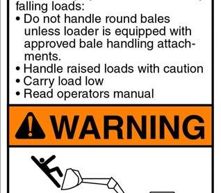
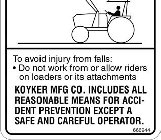


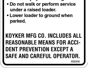
8 SAFETY DECALS Page 6
9 TRACTOR & SAFETY POINTERS The use of good judgment and common sense is necessary by the operator in using this loader. The front and rear wheels should be set for the widest wheel tread to assure best stability. Use extra caution when rear wheel weights and tire ballast are added to a loader-equipped tractor. DO NOT ram into frozen dirt piles, frozen manure piles, ice, etc., with great momentum where sudden shock loads are encountered. Serious and costly damage may result to both the loader and the tractor. When scraping or back dragging do not extend the attachment cylinders more than one half of the cylinder s stroke. A limited amount of leveling may be done, when the loader valving is arranged with a float control. This will prevent damage to cylinder rods. Never ride in the bucket. Before operating the loader, be sure no one is standing near it. Only one person, the operator, should be on the tractor. Remain at the controls and under no circumstances leave the tractor unattended with the bucket in a raised position. Never lift a person in the bucket or walk under a raised bucket. Never drive your loader-equipped tractor down a hill that is steeper than 15 degrees. Carry all loads low and use care on side hills. Always keep unused PTO shaft clutch levers disengaged. Keep hands, feet, and clothing away from all moving parts. Hydraulic oil, under pressure, can cause injury. Be sure that all connections are tight and that all pressure is relieved before disconnecting any lines. Care must be taken with your loader cylinders. Nicks, scratches, rust, or other shaft damage can result in worn packing causing cylinder leakage and subnormal performance. MOVE SLOWLY USE COMMON SENSE BE CAREFUL FOR YOUR OWN SAKE AND THAT OF OTHER PEOPLE Page 7
10 ATTACHING LOADER IMPORTANT: Never attempt to attach loader on grades which are not reasonably level. 1. Check to be sure that the surfaces of the mounts are free of obstructions. 2. Drive the tractor slowly and carefully in between the loader arms only far enough to permit coupling of the hydraulic system hoses. (Fig. 8-1) Fig Once all hoses have been properly coupled, drive the tractor slowly forward, watching to ensure that the bottom pivot cradle(s) clear the pivot pin(s), in the lower portion of the mount(s). (Fig. 8-2) 4. Allow the bottom pivot cradle(s) to settle onto the mount pivot pin(s). Slowly raise loader and dump bucket until both uprights are firmly located in the mounts. The back of the upright should be vertical. (Fig. 8-3) 5. To lock the loader onto the mount(s), install a 1-1/4 square mount pin (689302) through the square opening in the mount (both mounts). (Fig. 8-4) 6. Once the mount pin is completely engaged, lock the pin in place by positioning the mount pin handle through the slot opening in the mount retaining plate. (Fig. 8-5) Fig 8-2 Fig 8-3 Fig 8-4 Fig 8-5 Page 8
11 ATTACHING LOADER (continued) IMPORTANT: Never attempt to attach loader on grades which are not reasonably level. 7. To secure the loader to the mount, lower the mount wedge block into place by tightening the 12mm mount bolt at the back of the mount tower. (Fig. 9-1) Re-check bolts after first three hours of use. 8. After both uprights are secured to the mounts, raise the loader for leg stand removal and storage. Raise the loader until the loader bucket is approx. 24 off of the ground. (Fig 9-2) Fig With the bottom portion of leg stand supported, remove the 5/8 hitch pin (689571). (Fig 9-3) 10. Align the inner leg studs of the leg stand with the slots of the leg stand rail and slide the leg stand up the loader arm. (Fig 9-4) 11. Reinstall the 5/8 hitch pin (689571) as shown in Fig 9-5. The hitch pin will rest at the bottom of the leg stand rail. Fig Prior to operation, be certain to review all safety and operation information contained within this manual. Check mount bolts at the back of the mount tower after the first 3 hours of use and then check periodically during normal maintenance procedure. Fig 9-3 Fig 9-4 Fig 9-5 Page 9
12 ATTACHING JD SERIES BUCKET 1. For attachment of the bucket, first tilt the bucket adapter forward so the cradles at the top of the adapter are below the cross bars on the back of the bucket. (Fig. 10-1). If the cradles do not line up with each other, tilt the bucket adapters rearward until they both once again in line and restart the procedure. While slowly driving forward, raise the loader and tilt the bucket adapter rearward until the adapter cradles come in contact with bucket cross bars. (Fig 10-2) Once both cradles are firmly engaged, continue to tilt the bucket adapter rearward until the lower mount pads of the adapters firmly contact the back of the bucket. (Fig 10-3) Carefully raise the latch pins (690020) off of their rest and allow them to engage, locking the bucket in place. (Fig 10-4) If the bucket is mounted with a grapple, auxiliary hydraulic lines will need to be connected prior to operation. Fig 10-1 Fig 10-2 Fig 10-3 Fig 10-4 Page 10
13 ATTACHING GLOBAL BUCKET 1. For attachment of the bucket, first tilt the bucket adapter forward so the adapter top bar is below the top hooks (mounts) on the back of the bucket. (Fig. 11-1). While slowly driving forward, raise the loader and tilt the bucket adapter rearward until the adapter come s in contact with bucket cross bars. (Fig 11-2) Once the adapter is firmly engaged, continue to tilt the bucket rearward until the lower mount pads of the adapter firmly contact the back of the bucket. (Fig 11-3) Carefully push the latch handles off of their rest or over center and allow them to engage, locking the bucket in place. (Fig 11-4) If the bucket is mounted with a grapple, auxiliary hydraulic lines will need to be connected prior to operation. Fig 10-5 Fig 10-6 Fig 10-7 Fig 10-8 Page 11
14 DETACHING LOADER IMPORTANT: Never attempt loader detachment on grades which are not reasonably level. 1. With the loader raised off of the ground, dump the bucket to approximately 40 degrees from level. 2. Disengage the mount wedge block by loosening the 12 mm mount bolt at the back of the mount tower. (Fig 11-1) Fig Slowly lower the loader until it contacts the ground and apply slight down pressure. DO NOT raise the front tractor tires off of the ground. 4. Remove the 5/8 hitch pin (689571) as shown in Fig The hitch pin and allow the leg stand to slide down the leg stand rail. 5. Align the inner leg studs of the leg stand with the slots of the leg stand rail and rotate the leg stand rearward until the inner leg studs are outside the leg stand rail. (Fig 11-3) Fig Rotate the bottom of the leg stand rearward and align mount holes of the leg stand and loader arm. Install 5/8 hitch pin (689571). (Fig 11-4) Fig 11-3 Fig 11-4 Page 12
 from the mount and upright of the loader. (Fig 12-1) Store the square mount pin vertically in the mount retaining plate. 9.")

15 DETACHING LOADER (continued) IMPORTANT: Never attempt loader attachment on grades which are not reasonably level. 8. Remove the 1-1/4 square mount pin (689302) from the mount and upright of the loader. (Fig 12-1) Store the square mount pin vertically in the mount retaining plate. 9. With tractor in neutral and parking brake DISENGAGED extend the lift cylinders until there is approximately 2 between the back of the upright and the back of the mount. (Fig 12-2) Fig Slowly roll the bucket rearward until the leg stands contact the ground. Pay special attention that they both contact the ground evenly. If uneven ground is present, shim the leg stand with flat solid material. (Fig 12-3) 11. Continue to slowly roll the bucket rearward until the pivot cradle(s) of the upright(s) come off of the pivot pins of the mounts. One may need to slowly drive the tractor ahead as the uprights come out of the mount to keep slack in the hydraulic hoses to the loader. (Fig 12-4) 12. Retract the lift cylinders completely and detach the hydraulic hoses to the loader. Fig 12-2 Fig 11-1 IMPORTANT: Never store the detached loader where insufficient soil bearing capacity exists. Good firm clay or firmly packed dirt are sufficient, providing the area is dry. If you are unsure, use blocking under the stand foot to disperse the load. Failure to heed, may allow the loader to settle and prevent attachment at a later date. Fig 12-3 Fig 12-4 Page 13
16 DETACHING JD SERIES BUCKET 1. If the bucket is mounted with a grapple the auxiliary hydraulic lines need to be disconnected prior to detachment of the bucket. For detachment of the bucket, first ensure the bucket is resting on flat ground. (Fig 13-1) Disengage the latch pins (690020) and position them onto their rest(s). (Fig 13-2) Slowly lower the loader while tilting the bucket adapters forward. (Fig 13-3) Drive rearward until both adapters have cleared the bucket. (Fig 13-4) Fig 13-1 Fig 13-2 Fig 13-3 Fig 13-4 Page 14
17 DETACHING GLOBAL BUCKET 1. If the bucket is mounted with a grapple the auxiliary hydraulic lines need to be disconnected prior to detachment of the bucket. For detachment of the bucket, first ensure the bucket is resting on flat ground. Disengage the handle latch pins (Fig 13-5) and position them onto their rest(s). (Fig 13-6) Slowly lower the loader while tilting the bucket adapter forward. (Fig 13-7) Drive rearward until global adapter has cleared the bucket. (Fig 13-8) Fig 13-5 Fig 13-6 Fig 13-7 Fig 13-8 Page 15
18 OPERATION WARNING: FILLING THE BUCKET: Never allow anyone to operate the loader until they have carefully reviewed and understood this owners manual. When manure is piled on a slope, it is best to drive tractor up the slope straight into the pile. Operating sideways on a slope has a tendency to tip the loading unit. Drive tractor straight into the pile, raise the bucket about six inches, then drop bucket and drive forward until the bucket is filled. Tilt bucket completely back, raise main frame and back away from manure pile. DUMPING THE BUCKET: When dumping, bring the bucket to proper dumping height which is just high enough so it will not strike the spreader as the load is being dumped. With the bucket tipped, drive tractor forward and raise the bucket at the same time to distribute the load evenly into spreader or conveyance. RAISING THE BUCKET: WARNING: Make sure material in bucket cannot spill out on to tractor when loader boom is raised. Keep clear of overhead obstructions such as trees, limbs or power lines when raising the bucket. Side cutting is the best method of reducing large stockpiles. If the sides of the pile are too high, use the loader to pull them down and reduce the possibility of slides. Make sure you keep all lines, cylinders, and complete hydraulic system free of all sand, dirt, and foreign matter. Use only clean oil in the hydraulic system. When removing the loader from the tractor, be sure to plug all open ports. If the loader will be out of service for several days or longer, grease the exposed polished piston shafts on the bucket and the lift cylinders. WARNING: NEVER attempt to operate the loader with someone near the loader frame or bucket. If this loader is equipped with a Grapple fork, be sure Grapple teeth are closed before leaving seat of tractor. Page 16
19 Legend 740 SL SPECIFICATIONS SPECIFICATIONS Description of Equipment Rated Loader Model SL Lift Cylinder Dia /4 Bore Attachment Cylinder Dia /4 Bore Dimensional Specifications (A) *Maximum Lift Height to Pivot Pin (B) *Lift Height under Level Bucket (C) *Clearance with Bucket (D) *Reach at Maximum Lift Height... N/A (E) Maximum Dump Angle (F) *Reach with Bucket on Ground (G) Maximum Rollback Angle (H) *Digging Depth (J) *Overall Height in Carry Position Operational Specifications (U) *Lift Capacity to Maximum Height at Pivot Pin lbs. (V) *Lift Capacity to Maximum Height 31.5 Forward of Pivot Pin... N/A lbs. (Y) *Breakout Force at Ground Line at Pivot Pin lbs. (Z) *Breakout Force at Ground Line 31.5 Forward of Pivot Pin... N/A lbs. *Specifications based on ASABE standards S301.3 (Front-End Agricultural Loader Ratings) Variations in maximum lift height and other specs for different tractors are due to tire sizes, variations in loader mounting locations and hydraulic system efficiency. Specifications are subject to change without notice and without liability therefore. Page 17
20 Legend 740 NSL SPECIFICATIONS SPECIFICATIONS Description of Equipment Rated Loader Model NSL Lift Cylinder Dia /4 Bore Attachment Cylinder Dia /4 Bore Dimensional Specifications (A) *Maximum Lift Height to Pivot Pin (B) *Lift Height under Level Bucket (C) *Clearance with Bucket (D) *Reach at Maximum Lift Height... N/A (E) Maximum Dump Angle (F) *Reach with Bucket on Ground (G) Maximum Rollback Angle (H) *Digging Depth (J) *Overall Height in Carry Position Operational Specifications (U) *Lift Capacity to Maximum Height at Pivot Pin lbs. (V) *Lift Capacity to Maximum Height 31.5 Forward of Pivot Pin... N/A lbs. (Y) *Breakout Force at Ground Line at Pivot Pin lbs. (Z) *Breakout Force at Ground Line 31.5 Forward of Pivot Pin... N/A lbs. *Specifications based on ASABE standards S301.3 (Front-End Agricultural Loader Ratings) Variations in maximum lift height and other specs for different tractors are due to tire sizes, variations in loader mounting locations and hydraulic system efficiency. Specifications are subject to change without notice and without liability therefore. Page 18
21 LOADER INSPECTION, SERVICE AND MAINTENANCE Lower the bucket to the ground, shut off tractor engine and relieve the pressure in the hydraulic system before adjusting, lubricating or servicing the loader. Inspect all pins and grease fittings before each use and lubricate with heavy duty grease as indicated in this manual. Periodically check all bolts for looseness and re-torque if necessary. Before storage, be certain all hydraulic cylinders are fully collapsed so that the rod will not be exposed to the elements or damaged. Be certain hydraulic system remains sealed at all times to prevent contamination. Check and maintain an adequate fluid level in the tractor reservoir prior to use. Inspect all hydraulic system hoses and fittings. Replace prior to further operation if damaged. WARNING! Escaping hydraulic oil under pressure can penetrate the skin. Never use body to check for hydraulic leaks. Use cardboard when checking for leaks. See Fig Relieve hydraulic pressure before disconnecting any hydraulic line. Failure to heed may result in serious injury or death. FIG Page 19
22 740 SL LOADER PARTS DIAGRAM Page 20
23 740 SL LOADER PARTS DIAGRAM - (continued) Page 21
24 LOADER PARTS IDENTIFICATON SCHEDULE ITEM NO. PART NUMBER DESCRIPTION MAIN ASS./QTY MAINFRAME WLDT UPRIGHT WLDT LEVELING ARM WLDT RH LEVELING PLATE WLDT LH LEVELING PLATE WLDT SPACER X 1.75 X INDICATOR ROD WLDT INDICATOR SLEEVE WLDT /4" LIFT CYLINDER ASSEMBLY (740) /4" BUCKET CYLINDER ASSEMBLY (740) LHO REAR LINKAGE WLDT LHI LINKAGE WLDT RHI LINKAGE WLDT RHO REAR LINKAGE WLDT LH ADAPTER WLDT / FRONT LINKAGE WLDT - WLDT RH ADAPTER WLDT / FRONT LINKAGE WLDT - WLDT LEG STAND RAIL WLDT LEG STAND WLDT ADAPTER SHAFT HITCH PIN X /4" "E" CLIP /16" EXTERNAL SNAP RING OIL LINE CLAMP OIL LINE CLAMP - 6 LINES OIL LINE CLAMP TWIN HOSE CLAMP HOSE LINE CLAMP PIVOT PIN -.75 X PIVOT PIN X GREASEABLE PIVOT PIN X GREASEABLE PIVOT PIN X GREASEABLE PIVOT PIN X Page 22
25 LOADER PARTS IDENTIFICATON SCHEDULE - (continued) ITEM NO. PART NUMBER DESCRIPTION MAIN ASS./QTY PIVOT PIN X PIVOT PIN X PIVOT PIN X HYDRAULIC PRESSURE DECAL "DANGER DECAL" WARNING DECAL "LEGEND" DECAL - JOHN DEERE "740" DECAL SERIAL NUMBER DECAL WARNING DECAL LPACKAGE LDR 740 SL HYD HARDLINES OIL LINE #7 - TILT CYL HOSE EXT RH OIL LINE #8 - TILT CYL HOSE EXT LH WASHER - 5/16" FLAT NUT GR 2 CENTER LOCK SCREW X 1.00 GR5 HHC SCREW X 2.50 GR 5 HHC SCREW X 2.75 GR 5 HHC ZERK-1/4-28 GREASE FITTING - HYD ELB 90 10MJX-10ORM - ( ) FITTING -HYD 90 ELB 8MJIC - 10 ORM - ( ) FITTING - HYD ADA 8MJX - 10ORM FITTING - ADA 8FJX - 10MJX - ( ) HYD BLOCK ASSEMBLY KML8R16-10FJX-10ORM KML8R16-10FJX-10FJX KML6R16-8FJX-8FJX KML6R16-8FJX-8FJX-23 2 Page 23
26 740 SL GLOBAL LOADER PARTS DIAGRAM Page 24
27 740 SL GLOBAL LOADER PARTS DIAGRAM (continued) Page 25
28 740 SL GLOBAL LOADER PARTS DIAGRAM (continued) Page 26
29 PARTS IDENTIFICATION SCHEDULE ITEM NO. PART NUMBER DESCRIPTION QTY MAINFRAME WLDT UPRIGHT WLDT LEVELING ARM WLDT RH LEVELING PLATE WLDT LH LEVELING PLATE WLDT SPACER X 1.75 X INDICATOR ROD WLDT INDICATOR SLEEVE WLDT /4 LIFT CYLINDER ASSEMBLY (740) /4 BUCKET CYLINDER ASSEMBLY (740) LHO REAR LINKAGE WLDT LHI LINKAGE WLDT RHI LINKAGE WLDT RHO REAR LINKAGE WLDT LEG STAND RAIL WLDT LEG STAND WLDT HITCH PIN X /4 E CLIP /16 EXTERNAL SNAP RING OIL LINE CLAMP OIL LINE CLAMP - 6 LINES OIL LINE CLAMP TWIN HOSE CLAMP PIVOT PIN X GREASEABLE PIVOT PIN -.75 X PIVOT PIN X GREASEABLE PIVOT PIN X PIVOT PIN X PIVOT PIN X PIVOT PIN X HYDRAULIC PRESSURE DECAL DANGER DECAL WARNING DECAL LEGEND DECAL - JOHN DEERE DECAL SERIAL NUMBER DECAL WARNING DECAL LPACKAGE - LDR 740 HARDLINES OIL LINE #7 - TILT CYL HOSE EXT RH SCREW X 2.50 GR 5 HHC 14 Page 27
")
30 PARTS IDENTIFICATION SCHEDULE - (continued) Page 28
31 740 NSL LOADER PARTS DIAGRAM Page 29
32 740 NSL LOADER PARTS DIAGRAM - (continued) Page 30
33 PARTS IDENTIFICATION SCHEDULE ITEM NO. PART NUMBER DESCRIPTION MAIN ASS./QTY MAINFRAME WLDT UPRIGHT WLDT INDICATOR ROD WLDT INDICATOR SLEEVE WLDT /4" LIFT CYLINDER ASSEMBLY (740) /4" BUCKET CYLINDER ASSEMBLY (740 NSL) OUTSIDE REAR LINKAGE PLATE LHI REAR LINKAGE WLDT RHI REAR LINKAGE WLDT LH ADAPTER WLDT / FRONT LINKAGE WLDT - WLDT RH ADAPTER WLDT / FRONT LINKAGE WLDT - WLDT LEG STAND RAIL WLDT LEG STAND WLDT ADAPTER SHAFT HITCH PIN X /4" "E" CLIP /8" EXTERNAL SNAP RING /16" EXTERNAL SNAP RING OIL LINE CLAMP OIL LINE CLAMP - 6 LINES OIL LINE CLAMP TWIN HOSE LINE CLAMP ZERK-1/4-28 GREASE HOSE CLAMP PIVOT PIN -.75 X PIVOT PIN X SCREW X 2.75 GR 5 HHC SCREW X 2.50 GR 5 HHC 4 Page 31
34 PARTS IDENTIFICATION SCHEDULE - (continued) ITEM NO. PART NUMBER DESCRIPTION MAIN ASS./QTY WASHER - 5/16" FLAT NUT GR 2 CENTER LOCK SCREW X 1.00 GR5 HHC PIVOT PIN X PIVOT PIN X GREASEABLE PIVOT PIN X GREASEABLE PIVOT PIN X PIVOT PIN X "LEGEND" DECAL - JOHN DEERE SERIAL NUMBER DECAL WARNING DECAL "DANGER DECAL" WARNING DECAL "740" DECAL HYDRAULIC PRESSURE DECAL LPACKAGE LDR 740 NSL HARDLINES KML6R16-8FJX-8FJX KML6R16-8FJX-8FJX KML6R16-8FJX-8FJX FITTING - HYD ADA 8MJX - 10ORM FITTING -HYD 90 ELB 8MJIC - 10 ORM - ( ) FITTING-HYD 90 ELB 8 MJX - 8 ORM KML6R16-8FJX-8ORM OIL LINE SPACER - 1/2" 8 Page 32
35 740 NSL GLOBAL LOADER PARTS DIAGRAM Page 33
36 740 NSL GLOBAL LOADER PARTS DIAGRAM (continued) Page 34
37 740 NSL GLOBAL LOADER PARTS DIAGRAM (continued) Page 35
38 PARTS IDENTIFICATION SCHEDULE ITEM NO. PART NUMBER DESCRIPTION MAIN ASS./QTY MAINFRAME WLDT UPRIGHT WLDT INDICATOR ROD WLDT INDICATOR SLEEVE WLDT /4" LIFT CYLINDER ASSEMBLY (740) /4" BUCKET CYLINDER ASSEMBLY (740 NSL) OUTSIDE REAR LINKAGE PLATE LHI REAR LINKAGE WLDT RHI REAR LINKAGE WLDT LEG STAND RAIL WLDT LEG STAND WLDT HITCH PIN X /4" "E" CLIP /8" EXTERNAL SNAP RING /16" EXTERNAL SNAP RING OIL LINE CLAMP OIL LINE CLAMP - 6 LINES OIL LINE CLAMP TWIN ZERK-1/4-28 GREASE HOSE CLAMP PIVOT PIN -.75 X PIVOT PIN X PIVOT PIN X PIVOT PIN X GREASEABLE PIVOT PIN X PIVOT PIN X "DANGER DECAL" WARNING DECAL "740" DECAL "LEGEND" DECAL - JOHN DEERE SERIAL NUMBER DECAL WARNING DECAL HYDRAULIC PRESSURE DECAL LPACKAGE - LDR 740 NSL HARDLINES 1 35 Page 36
39 PARTS IDENTIFICATION SCHEDULE - (continued) ITEM NO. PART NUMBER DESCRIPTION MAIN ASS./QTY LPACKAGE LDR 740 NSL HARDLINES OIL LINE SPACER - 1/2" FITTING - HYD ADA 8MJX - 10ORM FITTING -HYD 90 ELB 8MJIC - 10 ORM - ( ) FITTING-HYD 90 ELB 8 MJX - 8 ORM NUT GR 2 CENTER LOCK SCREW X 1.50 GR 5 HHC SCREW X 1.00 GR5 HHC SCREW X 2.50 GR 5 HHC SCREW X 2.75 GR 5 HHC NUT GR 2 CENTER LOCK WASHER - 5/16" FLAT GLOBAL NSL MOUNT SD NSL GLOBAL MOUNT WELDMENT PIVOT PIN -.79" (20MM) X 8" COMPRESSION SPRING PIN 1 X 2 GLOBAL MOUNT PIN 1 X GLOBAL MOUNT CLEVIS PIN.5" X 1.5" COTTER PIN X PIN X 6.75 GLOBAL MOUNT WASHER - 1/2" FLAT N-SERIES NUT GR 2 HEX FLEXLOCK THIN " EXTERNAL SNAP RING SCREW X 2.75 GR 5 HHC NUT GR 2 CENTER LOCK ZERK-1/4-28 GREASE HANDLE RH HANDLE LH SCREW X 2.70 GR 5 HHC ZP NUT GR 2 HEX HOOK UP.5" PIN FRONT LINKAGE WLDT HOSE LINE CLAMP 2 Page 37 2
40 JD SERIES BUCKET PARTS DIAGRAM Page 38
41 BUCKET PARTS SCHEDULE 8' 6" JOHN DEERE SERIES BUCKET ITEM NO. PART NUMBER DESCRIPTION QTY ' 6" JD BUCKET ASSEMBLY ' 6" JD BUCKET WELDMENT PIN-ROLL.25 X LATCH PIN SPRING.135 WIRE X 1.460ID X 4 4 BOLT-ON BLADE KIT (OPTIONAL) ITEM NO. PART NUMBER DESCRIPTION QTY ' 6" BUCKET BOLT-ON BLADE KIT ' 6" BOLT ON BUCKET BLADE SCREW X 2.00 GR 5 PH WASHER - 5/8" SPRING LOCK NUT GR 5 HEX 13 CLEVIS & SLING LINK KIT (OPTIONAL) ITEM NO. PART NUMBER DESCRIPTION QTY CLEVIS & SLING LINK KIT 1 8' JOHN DEERE SERIES BUCKET ITEM NO. PART NUMBER DESCRIPTION QTY ' JD BUCKET ASSEMBLY ' JD BUCKET WELDMENT PIN-ROLL.25 X LATCH PIN SPRING.135 WIRE X 1.460ID X 4 4 BOLT-ON BLADE KIT (OPTIONAL) ITEM NO. PART NUMBER DESCRIPTION QTY ' BUCKET BOLT-ON BLADE KIT ' BOLT ON BUCKET BLADE SCREW X 2.00 GR 5 PH WASHER - 5/8" SPRING LOCK NUT GR 5 HEX 13 CLEVIS & SLING LINK KIT (OPTIONAL) ITEM NO. PART NUMBER DESCRIPTION QTY CLEVIS & SLING LINK KIT 1 7' JOHN DEERE SERIES BUCKET ITEM NO. PART NUMBER DESCRIPTION QTY ' JD BUCKET ASSEMBLY ' JD BUCKET WELDMENT PIN-ROLL.25 X LATCH PIN SPRING.135 WIRE X 1.460ID X 4 4 BOLT-ON BLADE KIT (OPTIONAL) ITEM NO. PART NUMBER DESCRIPTION QTY BUCKET BOLT-ON BLADE KIT BOLT ON BUCKET BLADE SCREW X 2.00 GR 5 PH WASHER - 5/8" SPRING LOCK NUT GR 5 HEX 11 CLEVIS & SLING LINK KIT (OPTIONAL) ITEM NO. PART NUMBER DESCRIPTION QTY CLEVIS & SLING LINK KIT 1 Page 39
42 HYDRAULIC SYSTEM INFORMATION The hoses from the tractor valves are attached to the oil lines which are on the inside of the loader main frame. Re-check all joints to prevent leakage after loader is mounted and in operation. KEEP SYSTEM CLEAN - USE ONLY CLEAN OIL CAUTION! It is of utmost importance that the hydraulic system of this loader be kept free from dirt and foreign matter. All internal parts to the hydraulic system of your loader have been carefully cleaned, inspected, and plugged with protective caps before shipment. All protective caps should be kept in place until the hydraulic system is connected. NOTE: Over 75 percent of all hydraulic failure and service is caused by dirt, etc. in the system. REMEMBER - CLEAN OIL MEANS LONGER LIFE! Page 40
43 HYDRAULIC CYLINDERS INFORMATION IMPORTANT: Read these service tips before beginning assembly of cylinder gland or piston. 1. Keep seals clean from the time they are removed from package until they are installed. 2. Clean the groove or bore into which the seal is to be fitted before installing the seal. 3. Never touch the seal lip in handling. Always pick up the seal by its outer member. 4. Inspect each seal lip carefully for nicks, scratches, and dirt at time of installation. If dirty use a soft, clean cloth and carefully wipe off seal. DO NOT wipe seal with fingers, this only imbeds dirt in the seal. NEVER clean rubber related seals with a mineral based solvent! Clean rubber seals in denatured alcohol or non-mineral based solvents only. NOTE: Seals can be made more pliable and easier to install, if first heated in hydraulic oil to 160 F. Never use direct heat on any seals. Page 41
44 HYDRAULIC CYLINDER PARTS DIAGRAM Page 42
45 HYDRAULIC CYLINDER PARTS LIST 740 SL & NSL LIFT CYLINDER (Part No ) ITEM NO. PART NO. DESCRIPTION QTY Tube Weldment Locknut Piston Assembly Gland Assembly Rod Weldment SL BUCKET CYLINDER (Part No ) ITEM NO. PART NO. DESCRIPTION QTY Tube Weldment Locknut Piston Assembly Gland Assembly Rod Weldment NSL BUCKET CYLINDER (Part No ) ITEM NO. PART NO. DESCRIPTION QTY Tube Weldment Locknut Piston Assembly Gland Assembly Rod Weldment 1 Page 43
46 3 1/4 CYLINDER SERVICE KITS WITH 1 3/4 SHAFT KIT NO : Complete kit with all seals needed to service one (1) 3 1/4 Cylinder. Consists of: 1 each 3 1/4 Gland O Ring 1 each 3 1/4 Backup Ring 1 each 1 3/4 U-cup Seal 1 each 1 3/4 Rod Wiper 2 each 3 1/4 U-cup Seal 1 each 1 Rod O Ring 1 each 1 Locknut KIT NO : Complete assembled 3 1/4 Cylinder Gland with all seals. Consists of: 1 each 3 1/4 Aluminum Gland 1 each 3 1/4 Gland O Ring 1 each 3 1/4 Backup Ring 1 each 1 3/4 U-cup Seal 1 each 1 3/4 Rod Wiper 1 each 1 Locknut KIT NO : Complete assembled 3 1/4 Cylinder Piston with all seals. Consists of: 1 each 3 1/4 Aluminum Piston 2 each 3 1/4 U-cup Seal 1 each 1 Rod O Ring 1 each 1 Locknut KIT NO : All seals needed to service one (1) 3 1/4 Cylinder Gland. Consists of: 1 each 3 1/4 Gland O Ring 1 each 3 1/4 Backup Ring 1 each 1 3/4 U-cup Seal 1 each 1 3/4 Rod Wiper 1 each 1 Locknut KIT NO : All seals needed to service one (1) 3 1/4 Cylinder Piston. Consists of: 2 each 3 1/4 U-cup Seal 1 each 1 Rod O Ring 1 each 1 Locknut NOTE: Parts are only available in a kit form. Page 44
47 2 3/4 CYLINDER SERVICE KITS WITH 1 1/2 SHAFT KIT NO : Complete kit with all seals needed to service one (1) 2 3/4 Cylinder. Consists of: 1 each 2 3/4 Gland O Ring 1 each 2 3/4 Backup Ring 1 each 1 1/2 EZ Squeeze Rod Seal 1 each 1 1/2 Rod Wiper 2 each 2 3/4 EZ Squeeze Piston Seal 1 each 1 Rod O Ring 1 each 1 Locknut KIT NO : Complete assembled 2 3/4 Cylinder Gland with all seals. Consists of: 1 each 2 3/4 Aluminum Gland 1 each 2 3/4 Gland O Ring 1 each 2 3/4 Backup Ring 1 each 1 1/2 EZ Squeeze Rod Seal 1 each 1 1/2 Rod Wiper 1 each 1 Locknut KIT NO : Complete assembled 2 3/4 Cylinder Piston with all seals. Consists of: 1 each 2 3/4 Aluminum Piston 2 each 2 3/4 EZ Squeeze Piston Seal 1 each 1 Rod O Ring 1 each 1 Locknut KIT NO : All seals needed to service one (1) 2 3/4 Cylinder Gland. Consists of: 1 each 2 3/4 Gland O Ring 1 each 2 3/4 Backup Ring 1 each 1 1/2 EZ Squeeze Rod Seal 1 each 1 1/2 Rod Wiper 1 each 1 Locknut KIT NO : All seals needed to service one (1) 2 3/4 Cylinder Piston. Consists of: 2 each 2 3/4 EZ Squeeze Piston Seal 1 each 1 Rod O Ring 1 each 1 Locknut NOTE: Parts are only available in a kit form. Page 45


48 CYLINDER GLAND SERVICE DIAGRAM ROD WIPER All gland seals shown with a section removed to facilitate correct installation. Note: To install rod wiper and U-cup seal, fold similar to shape shown below, slip into gland bore and locate each in its respective groove. Tools are used to fold seals, take care not to damage sealing surfaces. U-CUP SEAL GLAND GLAND ROD WIPER BACK UP U-CUP SEAL BACK UP O-RING O-RING SECTION VIEW ASSEMBLED GLAND Important! Be sure all gland and piston seals have been installed correctly before cylinder is assembled! CYLINDER PISTON SERVICE DIAGRAM O-RING U-CUP SEAL To Remove Seals: Carefully cut across each seal with a sharp knife. Be sure not to scratch sealing surfaces of aluminum piston. If a sharp knife is not available. An electric soldering gun or hot iron may be used to melt throughout seals. To Install Seals: 1. Thoroughly clean piston sealing surface of all foreign matter. 2. Heat new seals in hydraulic oil to 160 F. Never use a direct flame or heated water on hydraulic seals. 3. Remove seals from oil, wipe dry and install in piston grooves as shown in illustration at left. Be sure seals have completely seated in piston grooves before allowed to cool. 4. Replace piston on cylinder shaft and assemble cylinder when seals have cooled to room temperature. PISTON O-RING U-CUP SEAL Page 46 SECTION VIEW ASSEMBLED PISTON U-CUP SEAL PISTON U-CUP SEAL
49 NEW LEGEND LOADER WARRANTY LIMITED WARRANTY FOR NEW LEGEND EQUIPMENT COMPANY PRODUCTS A. GENERAL PROVISIONS. Legend means Legend Equipment Company, 200 N. Cleveland, P.O. Box 409, Lennox, South Dakota The warranties described below are provided by Legend to the original purchasers of new products purchased from Legend or from an authorized Legend Dealer (the Products ). Under these warranties, Legend will, at its option, repair or replace at its factory any Product covered under these warranties which is found to be defective in material and workmanship during the applicable warranty term or refund the purchase price paid for the defective Product. Customer will be responsible for labor charges for removing the defective Product and reinstalling the repaired or replacement Product, any premium charge for overtime labor requested of Legend and shipping charges to and from Legend s factory. These warranties are not transferrable. B. WARRANTY PERIOD. Subject to exclusions and limitations set forth herein, each new Product is warranted for the number of years specified below. Each warranty term begins from the date of purchase regardless of delay in receipt of the Product by Customer due to the time required to process, handle, ship, assemble, construct and install the Product. Customer must retain proof of the date of purchase. Replacement parts for and repairs to the Product will be warranted only for the remainder of the original warranty term. The replacement parts for or repairs to the Product will not extend the warranty term beyond the original warranty term. Products include all parts, components and accessories. Legend Loaders PRODUCTS Consumer Use Commercial or Government Use 2 years C. ITEMS COVERED SEPARATELY. The Legend warranties do not cover any parts, components or materials that are part of the Product, or used in conjunction with the Product, that are not manufactured by Legend. Such parts, components and materials will be subject to the warranties provided by the manufacturer, if any. D. WHAT IS NOT WARRANTED. Legend does not warrant and is not responsible for the following: (1) used Products; (2) modification or alteration of the Products; (3) Products that have not been properly installed or not installed in accordance with the instruction manual, improper assembly, or improper construction by any persons other than Legend employees; (4) depreciation, damage or loss caused by the use of parts, components or accessories not provided by Legend, unauthorized repairs, normal wear, lack of necessary and proper maintenance, a failure to follow operating instructions/recommendations, misuse, lack of proper protection during storage, vandalism or theft, exposure to the elements or corrosive materials, accidents or acts of nature including lightning, flooding, hail, straight winds and tornadoes; and (5) cosmetic damage or damage that does not hinder the functionality of the Products. E. LIMITATIONS OF WARRANTIES AND CUSTOMER S REMEDIES. To the extent permitted by law, neither Legend, the Dealer nor any person or company affiliated with either of them makes any warranties, representations, conditions or promises express or implied as to the quality, performance or freedom from defects of the Products covered by these warranties other than those set forth herein. THERE ARE NO IMPLIED WARRANTIES OF MERCHANTABILITY OR FITNESS FOR A PARTICULAR PURPOSE. NEITHER LEGEND, THE DEALER, NOR ANY PERSON OR COMPANY AFFILIATED WITH EITHER OF THEM WILL BE LIABLE FOR ANY DAMAGES, INCLUDING, BUT NOT LIMITED TO, INCIDENTAL, SPECIAL, EXEMPLARY, CONSEQUENTIAL, LOST PROFITS AND REVENUES, LOST USE OF THE PROD- UCTS OR ANY OTHER PROPERTY, BODILY INJURY OR PROPERTY DAMAGE CLAIMS OF ANY PERSON, LOST COMMODITIES, RE- MOVAL OR STORAGE COSTS FOR THE PRODUCTS, OTHER EQUIPMENT AND COMMODITIES, DAMAGE TO THE ENVIRONMENT ARISING FROM OR IN ANY MANNER RELATED TO ANY RELEASE OF HAZARDOUS MATERIALS, AND REMEDIATION EXPENSES THEREFORE, WHETHER BASED ON CONTRACT, TORT, STRICT LIABILITY OR ANY OTHER LEGAL BASIS, EVEN IF ADVISED OF THE POSSIBILITY OF SUCH DAMAGES. IN NO INSTANCE WILL LEGEND, THE DEALER OR ANY PERSON OR COMPANY AFFILIAT- ED WITH EITHER OF THEM BE LIABLE TO CUSTOMER OR ANY PERSON IN AN AMOUNT IN EXCESS OF THE PURCHASE PRICE PAID BY CUSTOMER FOR THE PRODUCT. F. NO DEALER WARRANTY. THE DEALER HAS NO AUTHORITY TO MAKE ANY WARRANTY, REPRESENTATION, CONDITION OR PROMISE ON BEHALF OF LEGEND, OR TO MODIFY THE TERMS OR LIMITATIONS OF THIS WARRANTY IN ANY WAY. G. GOVERNING LAW/VENUE. These warranties, and all terms set forth herein, are governed by the laws of the State of South Dakota and, where applicable, the laws of the United States of America. Any and all disputes arising from these warranties, the purchase and use of the Products, bodily injury and property damage claims or otherwise must be venued in the South Dakota Circuit Court sitting in Minnehaha County, South Dakota. Customer agrees to such venue and waives any challenge to such court s jurisdiction based upon lack of personal jurisdiction or inconvenience. H. SECURING WARRANTY SERVICE. In order to receive warranty services, customer must give Legend written notice of a warranty claim within 30 days of the date of discovery of the defective materials or workmanship, and Customer must complete the following steps: (1) Obtain from Legend a Return Materials Authorization Number ( RMA Number ) by calling the Customer Service Department at (855) or Legend at info@legendequip.com, and providing the following information: An explanation as to why the Product is being returned. 1 year The name of the territory representative, Dealer or Legend salesperson from whom the Product was purchased. The Dealer s identification number. The invoice number and date of purchase. Customer s name, phone number, fax number, mailing address and address. The date that the Product will be returned. (2) Pay the shipping charges to ship the Product to Legend s factory, and the return shipping charges. (3) Ship the Product to Legend at 200 N. Cleveland, Lennox, South Dakota Page 47
50 TORQUE SPECIFICATIONS 1. Tightening Bolts & Nuts Check all loader bolts and nuts for tightness every 50 working hours. The movement of the loader over rough terrain may cause bolts to come under pressure and over a long period of time some slight stretching of the bolt may occur. The slack created may need to be taken up by tightening. Please refer below for recommended torque settings. Metric Recommended Torque Settings Class 8.8 Class 10.9 Lubricated Dry Lubricated Dry Size N*m Lb-ft N*m Lb-ft N*m Lb-ft N*m Lb-ft M M M M M M M M M M M M M M SAE Recommended Torque Settings Grade 5 Grade 8 Lubricated Dry Lubricated Dry Size N*m Lb-ft N*m Lb-ft N*m Lb-ft N*m Lb-ft 1/ / / / / / / / / / / / DO NOT use these values if a different torque value or tightening procedure is given for a specific application. Torque values listed are for general use only and include a +/- 10% variance. Check tightness of fasteners periodically. DO NOT use air powered wrenches. Shear bolts are designed to fail under predetermined loads. Always replace shear bolts with identical grade. Page 48


51 740 SPECIFICATIONS 740 Self-Leveling Specifications: Maximum lift height: 14 1 Digging depth: 12 Roll-back angle at ground level: 40 degrees Dump angle at maximum height: 70 degrees Reach at ground level: 8 2 Breakout force at pivot pin: 7,647 lbs. Lift capacity to full height at pivot pin: 4,083 lbs. 740 Non Self-Leveling Specifications: Maximum lift height: 13 8 Digging depth: 10 Roll-back angle at ground level: 29 degrees Dump angle at maximum height: 45 degrees Reach at ground level: 8 2 Breakout force at pivot pin: 8,171 lbs. Lift capacity to full height at pivot pin: 4,193 lbs. The 740 Is The FrontEnd Loader Solution To Fit The Following JD Series Tractors:
MANUAL NO CREATED: 08/08/2012 MMH REV A STEEL COMPANY R 65 BUSHEL MINI-BIN PARTS AND ASSEMBLY MANUAL
 MANUAL NO. 195988 CREATED: 08/08/2012 MMH REV A STEEL COMPANY R 65 BUSHEL MINI-BIN PARTS AND ASSEMBLY MANUAL TABLE OF CONTENTS SAFETY AND STATEMENTS OF IMPORTANCE... 2 GENERAL INFORMATION... 3 ASSEMBLY
SUPREME FEEDER MANUAL NO REV A / 09/02/ DOOR HOG FEEDER ASSEMBLY INSTRUCTIONS
 STEEL COMPANY R SUPREME FEEDER MANUAL NO. 166156 REV A / 09/02/2009 12 DOOR HOG FEEDER ASSEMBLY INSTRUCTIONS This feeder is designed for feeding an average hog from about 40 pounds up to about 250 pounds.
SIOUX STEEL MANUAL HEAD GATE #194538
 SIOUX STEEL MANUAL NO: 958 CREATED: /0 REV E: /0/0 ECN -0 MANUAL HEAD GATE #9458 PATENT PENDING #9/48, WARNING!: KEEP HANDS & FINGERS AWAY FROM ALL HINGED AND MOVING PARTS DURING OPERATION. SIOUX STEEL
Walker Loader Bucket OPERATOR S AND PARTS MANUAL
 Walker Loader Bucket OPERATOR S AND PARTS MANUAL Please Read and Save These Instructions For Safety, Read all Safety and Operation Instructions Prior To Operating Machine P/N 6690 TABLE OF CONTENTS Introduction
AG PRODUCTS, LTD. YOU RE ALWAYS AHEAD... WITH A MODERN BEHIND.
 SUMMER 2016 BADGER DISC HARROW Operator s Manual 011-1156 011-1166 001-1501 001-1501-1 011-1167 001-1501-2 001-1501-3 011-1176 001-1501-4 011-1177 MODERN AG PRODUCTS, LTD. YOU RE ALWAYS AHEAD... WITH A
OPERATORS MANUAL SAFETY & WARRANTY SECTION
 OPERATORS MANUAL SAFETY & WARRANTY SECTION KMW Ltd. 198 N. Hwy 281 Great Bend, Kansas 67530 800 445-7388 Fax 620 793-6737 ïïïkâãïäç~çéêëkåçã SAFETY FIRST This symbol, the industry s Safety Alert Symbol,
1000-LB. ENGINE STAND
 1000-LB. ENGINE STAND WARNING: Read carefully and understand all ASSEMBLY AND OPERATION INSTRUCTIONS before operating. Failure to follow the safety rules and other basic safety precautions may result in
2000-LB. ENGINE STAND
 2000-LB. ENGINE STAND WARNING: Read carefully and understand all ASSEMBLY AND OPERATION INSTRUCTIONS before operating. Failure to follow the safety rules and other basic safety precautions may result in
542 Legend Loader Parts Pricebook
 542 Legend Loader s Pricebook NEW PRICES EFFECTIVE NOVEMBER 1, 2013 Legend Loaders A Division of Sioux Steel Co., Inc. 200 North Cleveland; PO Box 409 Lennox, SD 57039 Telephone: (800) 855-534-3784 Fax:
Boring Unit Sitework Systems Attachment
 FORM NO. 6 Boring Unit Sitework Systems Attachment Model No. 0 89000 & Up Operator s Manual English (CE) Contents Page Introduction................................. Safety......................................
Operator s Manual. Go Galvanized! YOU'RE ALWAYS AHEAD...WITH A MODERN BEHIND.
 fall 2010 3pt & quick attach Bale spears & 3pt bale carrier Operator s Manual YOU'RE ALWAYS AHEAD...WITH A MODERN BEHIND. 318-1006-i 318-1005-i 020-1500 020-1502 P.O. Box 790 Beaumont, Tx 77704 409.833.2665
OWNER S MANUAL 40 LAWN AERATOR SAT-40 BH. Assembly Installation Operation Repair Parts. Visit us on the web! MODEL:
 OWNER S MANUAL 40 LAWN AERATOR MODEL: SAT-40 BH Assembly Installation Operation Repair Parts For the latest product updates & setup tips: Visit us on the web! www.brinly.com Important: This manual contains
OWNER S MANUAL Z SERIES TRACKS. Rev. 355_05
 OWNER S MANUAL Z SERIES TRACKS Rev. 355_05 LOEGERING 800-373-5441 15514 37 th Street SE 701-347-5441 Casselton, ND 58012 USA Fax: 701-347-4323 E-Mail: lmi@loegering.com Internet: www.loegering.com Loegering
Trench Filler for Compact Utility Loaders
 Form No. 3353-608 Rev A Trench Filler for Compact Utility Loaders Model No. 22472 260000001 and Up Operator s Manual Register your product at www.toro.com Original Instructions (EN) Contents Page Introduction................................
HydroTote Trailer Hydroject Aerator
 Form No. 3355 89 Rev. C HydroTote Trailer Hydroject Aerator Model No. 09833 Serial No. 6000000 and Up Operator s Manual English (EN, GB) Contents Page Introduction................................. Safety......................................
OPERATOR S AND PARTS MANUAL PALLET FORKS. Part Number: MODEL NUMBER: Rev. 4
 OPERATOR S AND PARTS MANUAL PALLET FORKS SERIAL NUMBER: Manual Number: OM642 Part Number: 75542 MODEL NUMBER: Rev. 4 800-456-7100 I www.paladinlcg.com 503 Gay Street, Delhi, IA 52223, United States of
W & A 12 ROW TOP LEVELING STACKER LEVEL BANDER
 W & A 12 ROW TOP LEVELING STACKER LEVEL BANDER NO. 3640 OPERATOR S MANUAL TO THE OWNER: Congratulations on your purchase of a new W & A Top Leveling Stacker Level Bander. Your selection is an indication
OWNER S MANUAL. LOEGERING th Street SE Casselton, ND USA Fax:
 OWNER S MANUAL TRAIL BLAZERS and D SERIES TRACKS LOEGERING 800-373-5441 15514 37 th Street SE 701-347-5441 Casselton, ND 58012 USA Fax: 701-347-4323 E-Mail: lmi@loegering.com Internet: www.loegering.com
1250 LB. CAPACITY MECHANICAL WHEEL DOLLY
 1250 LB. CAPACITY MECHANICAL WHEEL DOLLY 67287 SET-UP AND OPERATING INSTRUCTIONS Visit our website at: http://www.harborfreight.com Read this material before using this product. Failure to do so can result
POST HOLE DIGGER. Operation, Service & Parts Manual For Models D20 & D40. FORM: D20_40DigRev.QXD
 POST HOLE DIGGER Operation, Service & Parts Manual For Models D20 & D40 FORM: D20_40DigRev.QXD September 2006 Revised August 2009 TABLE OF CONTENTS Introduction.............................1 Preparation..............................2
CAUTION CAUTION indicates a potentially hazardous situation which, if not avoided, may result in minor or moderate injury.
 Instruction Manual Notes: Page Manual Conventions This manual uses the following symbols to help differentiate between different kinds of information. The safety symbol is used with a key word to alert
3-Pt. Quick Hitch. Owner s Manual
 3-Pt. Quick Hitch Owner s Manual WARNING: Read carefully and understand all ASSEMBLY AND OPERATION INSTRUCTIONS before operating. Failure to follow the safety rules and other basic safety precautions may
Instruction Manual. ATV Plow Tube System
 Instruction Manual ATV Plow Tube System Manual Conventions This manual uses the following symbols to help differentiate between different kinds of information. The safety symbol is used with a key word
610 BUSHEL MANURE SPREADER
 610 BUSHEL MANURE SPREADER RODA MANUFACTURING 1008 LOCUST ST. HULL, IA. 51239 Art s-way Manufacturing 712-439-2366 Co., Inc. Hwy 9 West - PO Box 288 WWW.RODAMFG.COM Armstrong, IA. 50514 U.S.A 2 INTRODUCTION
Wheel Horse. 44 Snowthrower. for 5xi Lawn and Garden Tractors. Model No & Up. Operator s Manual
 FORM NO. 8 Rev A Wheel Horse Snowthrower for 5xi Lawn and Garden Tractors Model No. 7966 890050 & Up Operator s Manual IMPORTANT: Read this manual, and your tractor manual, carefully. They contain information
Precision Reel Mowers OPERATOR S MANUAL
 Precision Reel Mowers OPERATOR S MANUAL Models RL205 / RL207 RL255 / RL257 / RL2510 Introduction Read this information carefully to learn how to operate and maintain your product properly and to avoid
Trencher Dingo Attachment
 Form No. 3326-453 Trencher Dingo Attachment Model No. 22459 2000000 & Up Operator s Manual English (CE) Contents Page Introduction................................ 2 Safety.....................................
Planting Components. Operator s/parts Manual. Row Cleaner VIII. Terra-Tine
 Operator s/parts Manual Terra-Tine Row Cleaner VIII Planting Components! Read the operator s manual entirely. When you see this symbol, the subsequent instructions and warnings are serious - follow without
Extreme Duty Grapple (Rock, Skeleton, Scrap & Tine) Operation and Maintenance Manual
 Operation and Maintenance Manual") Extreme Duty Grapple (Rock, Skeleton, Scrap & Tine) Operation and Maintenance Manual Revision Date: July 2017 Skid Pro PO Box 982 Alexandria, MN 56308 Toll Free: 877-378-4642 www.skidpro.com TABLE OF CONTENTS
Extreme Duty Grapple (Rock, Skeleton, Scrap & Tine) Operation and Maintenance Manual Revision Date: July 2017 Skid Pro PO Box 982 Alexandria, MN 56308 Toll Free: 877-378-4642 www.skidpro.com TABLE OF CONTENTS
3-Pt. Boom Pole. Owner s Manual
 3-Pt. Boom Pole Owner s Manual WARNING: Read carefully and understand all ASSEMBLY AND OPERATION INSTRUCTIONS before operating. Failure to follow the safety rules and other basic safety precautions may
Two-Stage Snow Blower For 4WD Pick Up Trucks. Operator s Manual
 Two-Stage Snow Blower For 4WD Pick Up Trucks Operator s Manual Distrubuted by: Metal Fabricating LLC P.O. Box 831 Brodheadsville, PA 18322 Phone: 570-992-9989 SnowVac.com WARRANTY POLICY Metal Fabricating
LOG CHOP. Hydraulic Wood Guillotine. Owners Illustrated Instruction Book & Parts List
 LOG CHOP Hydraulic Wood Guillotine Owners Illustrated Instruction Book & Parts List Grovebury Road, Leighton Buzzard, Bedfordshire. LU7 4UX. UK. Tel:01525 375157. Fax:01525 385222. Email: enquires@brownsagricultural.co.uk
3-Pt. Box Scraper. Owner s Manual
 3-Pt. Box Scraper Owner s Manual WARNING: Read carefully and understand all ASSEMBLY AND OPERATION INSTRUCTIONS before operating. Failure to follow the safety rules and other basic safety precautions may
TABLE OF CONTENTS. Warranty Disclaimers Delivery Checklist After Sale Checklist Safety Set Up... 8
 TABLE OF CONTENTS Pickett Equipment Warranty... 2 Warranty Disclaimers... 3 Delivery Checklist... 4 After Sale Checklist... 4 Safety... 5-7 Set Up... 8 Machine Adjustments and Operation... 9 Maintenance
KENCOVE PD100 MANUAL TILT POST DRIVER
 OPERATOR S MANUAL KENCOVE PD100 MANUAL TILT POST DRIVER WWW.KENCOVE.COM 800-536-2683 344 KENDALL RD, BLAIRSVILLE, PA 15717 Table of Contents Specifications/Requirements 1 Introduction 2 Equipment Inspection
Planting Components. Operator s/parts Manual
 Operator s/parts Manual Unit Mount Conservation Coulter and Spring Package Attachment for JD 7000, JD 7200, White 6100, Kinze Planters and Great Plains Row Units Planting Components! Read the operator
Instruction Manual. ATV Manual Plow Lift
 Instruction Manual ATV Manual Plow Lift Manual Conventions This manual uses the following symbols to help differentiate between different kinds of information. The safety symbol is used with a key word
W & A 12 ROW TOP LEVELING STACKER LEVEL BANDER
 W & A 12 ROW TOP LEVELING STACKER LEVEL BANDER NO. 3640 OPERATOR S MANUAL TO THE OWNER: Congratulations on your purchase of a new W & A Top Leveling Stacker Level Bander. Your selection is an indication
OPERATOR S MANUAL. 20-bu 3-Point Hitch Material Collection System. LP65048 Supplier ST /07/2017 English. North American Edition Printed in USA
 OPERATOR S MANUAL 20-bu 3-Point Hitch Material Collection System LP65048 Supplier ST48289 11/07/2017 English North American Edition Printed in USA Introduction Using Your Operator s Manual Read this entire
Operator s/parts Manual
 Operator s/parts Manual 3-Point Solid Stand Drills Pull Hitch Package Manufacturing, Inc. P.O. Box 5060 Salina, Kansas 67402-5060! Read the operator s manual entirely. When you see this symbol, the subsequent
Operating Instructions & Parts Manual
 Aluminum / Steel Hybrid Service Jack Operating Instructions & Parts Manual Model 26017 26028 26033 Capacity 1.5 Ton 2.5 Ton 3 Ton! This is the safety alert symbol. It is used to alert you to potential
John Deere TLS TLS Tractors MANUAL
 John Deere 600-00 6-6 TLS - TLS Tractors MANUAL 00 John Deere 600-00 6-6 TLS - TLS Tractors Blade, pivot frame Hydraulics Tractor fit-up, mounting Operation, maintenance Previous hydraulic system Attachments
Operating and Assembly Manual
 Model 470-/H/PRO/IC Operating and Assembly Manual Midwest Equipment Manufacturing, Inc. 5225 Serum Plant Road Thorntown, IN 46071 11-11-11 SAFETY RULES Remember, any power equipment can cause injury if
Wheel Horse. 36 Tiller. Model No & Up. Operator s Manual
 FORM NO. 8 9 Rev. A Wheel Horse 6 Tiller for Classic Garden Tractors Model No. 7970 690000 & Up Operator s Manual IMPORTANT: Read this manual carefully. It contains information about your safety and the
Case STX/NH TJ
 Case STX/NH TJ 0-0 Tractors MANUAL Case STX/NH TJ 0-0 Tractors Blades, pivot frames Tractor fit-up Dlock, mounting Hydraulics Operation, maintenance Safety, warranty Industrial Drive, Box 0 Regina, Sask.
3800 SERIES SINGLE HYDRAULIC LOCKING TOOLBAR
 3800 SERIES SINGLE HYDRAULIC LOCKING TOOLBAR 2565-774_REV_D 02/2018 OPERATOR S MANUAL PART IDENTIFICATION YETTER MANUFACTURING CO. FOUNDED 1930 Colchester, IL 62326-0358 Toll free: 800/447-5777 309/776-3222
CAB #11606 FOR John Deere X500, X520, X530, X534, X540
 CAB #11606 FOR John Deere X500, X520, X530, X534, X540 ASSEMBLY INSTRUCTIONS PARTS LIST IMPORTANT READ THIS MANUAL CAREFULLY AND KEEP FOR FUTURE REFERENCE CAUTION! REMOVE THE VINYL PANELS FOR TRANSPORT
Backhoe for Dingo Compact Utility Loaders
 Form No. 50-5 Backhoe for Dingo Compact Utility Loaders Model No. 60 000000 & Up Operator s Manual Original Instructions (EN/GB) Contents Page Introduction................................. Safety......................................
ROTARY TILLER. Operation, Service & Parts Manual For "AS" Series. FORM: ASTillerBook.QXD
 ROTARY TILLER Operation, Service & Parts Manual For "AS" Series FORM: ASTillerBook.QXD April 2002 TABLE OF CONTENTS Preparation......................................1 Assembly Instructions.............................2
1000-LB. MOTORCYCLE LIFT TABLE OWNER S MANUAL
 1000-LB. MOTORCYCLE LIFT TABLE OWNER S MANUAL WARNING: Read carefully and understand all ASSEMBLY AND OPERATION INSTRUCTIONS before operating. Failure to follow the safety rules and other basic safety
RED23305 Owner s Manual
 RED23305 Owner s Manual 5 foot, 3-Point Mounted Snow Blower 270 West Park Avenue Huron, SD 57350 866-526-5682 Serial Number: Date of Purchase: Red Devil Snow Blower See Figure 1. 1. The Red Devil Snow
Wheel Horse 48 Blade for 5xi Garden Tractors
 Form No. -9 Wheel Horse 8 Blade for 5xi Garden Tractors Model 7955 0000000 Operator s Manual Domestic English (EN) Contents Page Introduction................................ Installation.................................
QUADBOSS UTV STRAIGHT PUSH TUBE OWNER S MANUAL
 PAGE of 6 PART #938 QUADBOSS UTV STRAIGHT PUSH TUBE OWNER S MANUAL This owner s manual covers all aspects of your new push tube including assembly, replacement parts, installation, warranty, and troubleshooting.
Low Profile Service Jack Jack Stand Combo
 Low Profile Service Jack Jack Stand Combo Jack Stands Low Profile Service Jack U.S. Patent No. 6,199,379! This is the safety alert symbol. It is used to alert you to potential personal injury hazards.
Model 35 PARTS MANUAL
 Model 35 PARTS MANUAL Version 3-2007 Ashland Industries Inc. 1115 Rail Drive P.O. Box 717 Ashland, WI. 54806 Ph: 877-634-4622 Toll Free Ph: 715-682-4622 Fx: 715-682-9717 www.ashlandind.com Model 35 Scraper
4400-Lb. Capacity Pallet Jack
 Read carefully and understand all ASSEMBLY AND OPERATION INSTRUCTIONS before operating. Failure to follow the safety rules and other basic safety precautions may result in serious personal injury. Item#
Operating and Assembly Manual
 Model 455-IC/PRO/H Operating and Assembly Manual Midwest Equipment Manufacturing, Inc. 5225 Serum Plant Road Thorntown, IN 46071 03-08-12 SAFETY RULES Remember, any power equipment can cause injury if
Hydraulic Wheel Dolly
 Hydraulic Wheel Dolly Operating Instructions & Parts Manual Model Number HW93766 Capacity 3/4 Ton Made in the U.S.A. This is the safety alert symbol. It is used to alert you to potential personal injury
Operation and Safety Manual
 Barrel Handler Operation and Safety Manual EZ SPOT UR Inc. 803 25 th St. N Fargo, ND 58102 Toll Free: 877 433 5733 Phone: 701 282 2772 Fax: 701 277 4625 Table of Contents Safety Symbols & Equipment Signs...
Operator s Manual. Go Galvanized! YOU'RE ALWAYS AHEAD...WITH A MODERN BEHIND.
 SUMMER 2008 rock & landscape rake Operator s Manual 003-7445 003-7450 003-7460 003-7440 003-7445 003-7450 YOU'RE ALWAYS AHEAD...WITH A MODERN BEHIND. P.O. Box 790 Beaumont, Tx 77704 409.833.2665 1.800.231.8198
Wheel Horse. 48 Snow/Dozer Blade. Model No & Up. Operator s Manual
 FORM NO. 9 878 Rev A Wheel Horse 8 Snow/Dozer Blade for 5xi Lawn and Garden Tractors Model No. 7955 890000 & Up Operator s Manual IMPORTANT: Read this manual, and your tractor manual, carefully. They contain
Owner's Manual LAWN AERATOR MODELS: PA-40 BH PA-48 BH. Assembly Installation Operation Repair Parts
 Owner's Manual LAWN AERATOR MODELS: PA-40 BH PA-48 BH Assembly Installation Operation Repair Parts For use with Riders and Lawn/Garden Tractors IMPORTANT This manual contains information for the safety
Installation Instructions
 85-3511 rev. 04 11-15 Installation Instructions Polyurethane Bushing Kit for Ford F-53 (Front) (replaces OE bushings and brackets) part #4139-127 1-5/8 diameter INTRODUCTION Thank you for purchasing this
WARRANTY REGISTRATION AND POLICY
 WARRANTY REGISTRATION AND POLICY Buhler Manufacturing products are warranted for a period of twelve (12) months from original date of purchase, by original purchaser, to be free from defects in material
Operating and Assembly Manual
 Model 455-IC/PRO/H Operating and Assembly Manual Palmor Products Inc. 5225 Serum Plant Road Thorntown, IN 46071 03-08-12 SAFETY RULES Remember, any power equipment can cause injury if operated improperly
Model 452-DIC/DH. Operating and Assembly Manual
 . Model 452-DIC/DH Operating and Assembly Manual Palmor Products Inc. 5225 Serum Plant Road Thorntown, IN 46071 02-14-12 SAFETY RULES Remember, any power equipment can cause injury if operated improperly
Elgin Hydraulic Clutch-Brake ECB-240, Product Number FORM NO. L F FORM NO. L F-0704
 Elgin Hydraulic Clutch-Brake ECB-20, Product Number 96225 FORM NO. L-20283-F-070 1 FORM NO. L-20283-F-070 In accordance with Nexen s established policy of constant product improvement, the specifications
TABLE OF CONTENTS DESCRIPTION. Safety Instructions & Safety Sign Locations Operating Instructions Assembly Instructions...
 TABLE OF CONTENTS DESCRIPTION PAGE Warranty... 1 Safety Instructions & Safety Sign Locations... 2 Operating Instructions... 3 Assembly Instructions... 5 500 & 600 Snowblower Drawings... 8 500 & 600 Snowblower
IMPORTANT READ ME FIRST
 IMPORTANT READ ME FIRST Thank you for purchasing your Kushlan Mixer. We hope that you will enjoy using it for many years to come. SHOULD YOU REQUIRE ANY SET-UP OR OPERATING ASSISTANCE WITH YOUR PRODUCT,
84in. Driveway Drag. Owner s Manual
 84in. Driveway Drag Owner s Manual WARNING: Read carefully and understand all ASSEMBLY AND OPERATION INSTRUCTIONS before operating. Failure to follow the safety rules and other basic safety precautions
Multi-Purpose Tool Sitework Systems Attachment
 FORM NO. 22 648 Multi-Purpose Tool Sitework Systems Attachment Model No. 2242 89000 & Up Operator s Manual English (CE) Contents Page Introduction................................. 2 Safety......................................
Long Chassis Hydraulic Service Jacks
 Model BH6011 Long Chassis Hydraulic Service Jacks Operating Instructions and Parts Manual Capacity 10 Ton Model BH6011 U.S. Patent No's. 5,946,912 5,341,723! This is the safety alert symbol. It is used
7.3L POWERSTROKE BANJO BOLT KIT Fits L Powerstroke Diesel. Installation Guide
 7.3L POWERSTROKE BANJO BOLT KIT Fits 94-03 7.3L Powerstroke Diesel Installation Guide INSPECT CONTENTS OF THIS KIT THOROUGHLY BEFORE STARTING THE INSTALLATION PROCESS! IF YOU FIND A PROBLEM WITH YOUR PACKAGE:
Model P-40 & Model P-25 POWER PUSHER
 Power Pusher Description INSTRUCTION MANUAL The Power Pusher provides ram capability by using the spreading power of the POWER HAWK P-16 Rescue Tool. (The Power Pusher may also be used with other spreader
Operating Instructions & Parts Manual
 Swift Lift Hydraulic Service Jack Operating Instructions & Parts Manual Model Number ATD7341 Capacity 3-1/2 Ton U.S. Patent No's. 5,946,912 6,199,379! This is the safety alert symbol. It is used to alert
36 Rear Discharge Mower
 FORM NO. 8 95 Rev. A Wheel Horse 6 Rear Discharge Mower for Classic Garden Tractor Model No. 7805 790000 & Up Operator s Manual IMPORTANT: Read this manual carefully. It contains information about your
ProLine. 44 Mower. for 120 Traction Unit. Model No & Up. Operator s Manual
 FORM NO. 9 ProLine Mower for 0 Traction Unit Model No. 05 99000 & Up Operator s Manual IMPORTANT: Read this manual carefully. It contains information about your safety and the safety of others. Also become
Manual Operated Floor Jack
 Manual Operated Floor Jack OPERATING INSTRUCTIONS Note: There may be some slight differences in the appearance of the various manually-operated floor jacks, however the instructions in this manual apply
DeZURIK 2 20" BOS BUTTERFLY VALVES
 2 20" BOS BUTTERFLY VALVES Instruction D10459 October 2013 2-20 BOS Butterfly Valves Instructions These instructions provide information about BOS Butterfly Valves. They are for use by personnel who are
MODEL L/R/EF Sectional Tire Spreader
 MODEL L/R/EF Sectional Tire Spreader Installation, Operation & Repair Parts Information Branick Industries, Inc. 4245 Main Avenue P.O. Box 1937 Fargo, North Dakota 58103 REV08032016 P/N: 81-0195E TABLE
Owner s Manual & Safety Instructions
 Owner s Manual & Safety Instructions Save This Manual Keep this manual for the safety warnings and precautions, assembly, operating, inspection, maintenance and cleaning procedures. Write the product s
Wheel Horse. 48 Snow Blade. Model No & Up. Operator s Manual
 FORM NO. 8 8 Wheel Horse 8 Snow Blade for Classic Graden Tractors Model No. 7950 890000 & Up Operator s Manual IMPORTANT: Read this manual carefully. It contains information about your safety and the safety
Operator Manual. Includes operating, adjustment, maintenance, technical, repair parts, and safety instructions for the 8A Bumper Attachment.
 8A BUMPER ATTACHMENT Operator Manual Includes operating, adjustment, maintenance, technical, repair parts, and safety instructions for the 8A Bumper Attachment. Please retain this document for future reference.
CAB #11670 FOR JOHN DEERE 2320 TRACTOR
 CAB #11670 FOR JOHN DEERE 2320 TRACTOR OPERATION - PARTS LIST - ASSEMBLY IMPORTANT READ THIS MANUAL CAREFULLY AND KEEP FOR FUTURE REFERENCE CAUTION! REMOVE THE VINYL PANELS FOR TRANSPORT IN AN OPEN TRUCK
36 Tiller Wheel Horse Lawn and Garden Tractor Attachment
 Form No. 9 6 Rev B 6 Tiller Wheel Horse Lawn and Garden Tractor Attachment Model No. 797 890000 and Up Operator s Manual English(En) Contents Page Introduction................................ Safety.....................................
OWNER'S MANUAL L A W N R O L L E R PRT-481S BH. Safety Assembly Operation Repair Parts Maintenance. Visit us on the web!
 OWNER'S MANUAL L A W N R O L L E R ROLLER MODEL: PRC- BH PRT- BH PRT-S BH PRT-S BH Safety Assembly Operation Repair Parts Maintenance Recommended for use with Riding Mowers, Lawn or Garden Tractors, and
1000-lb Hydraulic Truck Crane
 1000-lb Hydraulic Truck Crane Owner s Manual WARNING: Read carefully and understand all ASSEMBLY AND OPERATION INSTRUCTIONS before operating. Failure to follow the safety rules and other basic safety precautions
Installation Instructions
 85-4341 rev. 04 10-15 Installation Instructions Thank you for purchasing this antisway bar kit. Please read through these instructions before installation. Rear Anti-Sway Bar Kit for Chevy 2500/3500/4500
New Holland & 8670A A Buhler Genesis 2145/2160/2180/2210
 New Holland 0-90 0A - 90A Buhler Genesis 1/10/10/ Tractors MANUAL 191 New Holland 0-90 0A - 90A Buhler Genesis 1/10/10/ Tractors Blade, pivot frame 1 Hydraulics Tractor fit-up, mounting Operation, maintenance
LUBRICATOR GUN INSTRUCTIONS-PARTS LIST. 10,000 psi (700 bar) Maximum Delivery Pressure. Detachable-type
 Maximum Delivery Pressure. Detachable-type") INSTRUCTIONS-PARTS LIST 306 460 INSTRUCTIONS This manual contains important warnings and information. READ AND KEEP FOR REFERENCE. Rev. E Supercedes D Detachable-type LUBRICATOR GUN 10,000 psi (700 bar)
INSTRUCTIONS-PARTS LIST 306 460 INSTRUCTIONS This manual contains important warnings and information. READ AND KEEP FOR REFERENCE. Rev. E Supercedes D Detachable-type LUBRICATOR GUN 10,000 psi (700 bar)
Operator s Manual. Twin Rear Bagger For FastAttach Compatible Lawn Tractors
 Operator s Manual Twin Rear Bagger For FastAttach Compatible Lawn Tractors Models OEM-190-601 (for 38-inch & 42-inch decks) OEM-190-602 (for 46-inch decks) MTD PRODUCTS INC. P.O. BOX 368022 CLEVELAND,
MODEL NO & UP SAFETY INSTRUCTIONS. Keep this Operator s Manual in the plastic tube behind the operator seat.
 FORM NO. 94-7276 MODEL NO. 41026-60101 & UP OPERATOR S INSTRUCTIONS HOSE REEL KIT To assure maximum safety, optimum performance, and to gain knowledge of the product, it is essential that you or any other
PART'S MANUAL. Rear Mounted Blade RHINO
 850 Revised 06-10 PART'S MANUAL Rear Mounted Blade Part No. 00787017P An Operator's Manual was shipped with the equipment in the Manual Canister. This Operator's Manual is an integral part of the safe
Safety Information and Floatation Guide
 Safety Information and Floatation Guide ATV Safety Using J-wheelz on your ATV DOES NOT MAKE YOUR ATV SAFER! Using J-wheelz on your ATV will make your vehicle wider. This increases the risk of running into
1300 Dozer Owner s Manual & Parts Book
 300 Dozer Owner s Manual & Parts Book Purchase Date Serial Number Model Number Tractor Model Dealer PN: 3-2472 0--2008 Contents Description Page To The Owner 2 Maintenance & Caution 2 Safety Precautions
48 Side Discharge Mower
 FORM NO. 9 650 Rev A Wheel Horse 8 Side Discharge Mower for Classic Garden Tractor Model No. 786 890000 & Up Operator s Manual IMPORTANT: Read this manual carefully. It contains information about your
THE TRACTOR AND/OR LOADER (IF EQUIPPED)
") THE TRACTOR AND/OR LOADER (IF EQUIPPED) Read the tractor and/or loader operator s manual to learn how to operate your tractor and/or loader safely. Failure to do so could result in serious injury or death
THE TRACTOR AND/OR LOADER (IF EQUIPPED) Read the tractor and/or loader operator s manual to learn how to operate your tractor and/or loader safely. Failure to do so could result in serious injury or death
Operating and Assembly Manual
 Model 380/385-IC/385-LH Operating and Assembly Manual Midwest Equipment Manufacturing, Inc. 5225 Serum Plant Road Thorntown, IN 46071 2-0916 SAFETY RULES Remember, any power equipment can cause injury
16K and 19K Sidewinder TM Service Kit Instructions 86005
 86005 Equipment Required: Wrenches: 15/16, 1 1/8, Torque Wrench, Rubber Mallet Included Service Kit Items: 1 Qty. (1) Wear Plate 2 Qty. (6) 5/8 Conical Washer 3 Qty. (2) Wedge Bolt, 5/8-11 X 1 3/4 GRD
Lubricator Gun: 10,000 psi (700 bar) Maximum Delivery Pressure when disconnected from Dispenser
 Maximum Delivery Pressure when disconnected from Dispenser") INSTRUCTIONS-PARTS LIST 30 455 INSTRUCTIONS This manual contains important warnings and information. READ AND KEEP FOR REFERENCE. Rev. C Supercedes B Hand-Operated Portable Grease Dispenser Buckshot Luber
INSTRUCTIONS-PARTS LIST 30 455 INSTRUCTIONS This manual contains important warnings and information. READ AND KEEP FOR REFERENCE. Rev. C Supercedes B Hand-Operated Portable Grease Dispenser Buckshot Luber