CK 61 OPERATING INSTRUCTIONS
|
|
|
- Lilian Hunter
- 5 years ago
- Views:
Transcription

1 CK 61 OPERATING INSTRUCTIONS
2 2

3 Declaration of conformity The undersigned manufacturer: SAINT - GOBAIN ABRASIVES S.A. 190, BD J.F. KENNEDY L BASCHARAGE Declares that this product: Floor saw: CK61 D KSA Code: is in conformity with the following Directives: European Machinery Directive 2006/42/EC Electromagnetic Compatibility Directive 2004/108/EC and European standard: EN Floor cutting-off machines Safety Pierre Mersch Business Manager Machines Europe 3
4 4
5 CK61 OPERATING INSTRUCTIONS 1 Basic Safety Instructions Symbols Machine plate Safety instructions for particular operating phases 8 2 General description of the CK Short description Layout Technical data 11 3 Assembly and commissioning Tool assembly Left or right cut Water cooling system Starting the machine 13 4 Transport and Storing Securing for transport Transport procedure Long period of inactivity 14 5 Operating the CK Site of work Cutting method 15 6 Maintenance and service Maintenance of the machine Maintenance of the engine 19 7 Faults: causes and cures Fault-finding procedures Trouble-shooting guide Customer service 25 5
 as well as of industrial cement.")


6 1 Basic Safety Instructions The CK61 is exclusively designed for the cutting of floors made of asphalt, green and cured concrete (reinforced or not) as well as of industrial cement. Uses other than the manufacturer's instructions shall be considered as contravening the regulations. The manufacturer shall not be held responsible for any resulting damage. Any risk shall be borne entirely by the user. Observing the operating instructions and compliance with inspection and servicing requirements shall also be considered as included under use in accordance with the regulations. 1.1 Symbols Important warnings and pieces of advice are indicated on the machine using symbols. The following symbols are used on the machine: Read operator s instructions Ear protection shall be worn Rotation direction of the blade Never move the machine with the blade running idle. Set the handle in this position to move the machine forwards Set the handle in this position to move the machine backwards Set the handle in this position to disengage the clutch Set the handle in this position to engage the clutch 6


7 Press the button in this direction to raise the blade Press the button in this direction to lower the blade Parking brake on Parking brake off Emergency Stop Danger: risk of cut 7

8 1.2 Machine plate Important data can be found on the following plate located on the machine: Machine model Machine code Weight Year of production Maximum blade diameter Bore diameter Machine type Serial number Power 1.3 Safety instructions for particular operating phases Safety standard Blade speed Before commencing work Before commencing work, make yourself familiar with the working environment at the place of use. The working environment includes: obstacles in the area of work and manoeuvre, the firmness of the floor, necessary protection at the site relating to public thoroughfares and the availability of help in the event of accidents. Check for correct mounting of the blade regularly. Immediately remove damaged or badly worn blades, as they endanger the operator whilst rotating. Always cut with the blade guard in position. Only fit NORTON diamond blades to the machine! The use of other tools can damage the machine! Attention is drawn to the use of BS2092 safety goggles in conformity with specified Processes No.8 of the Protection of Eyes Regulation 1974, Regulation 2(2) Part 1. For security reasons, never leave the machine unattended, untied or unlocked. While the engine is running Do not move the machine whilst the blade is running idle. Do not run the machine without the security guards in place. Apply cooling water continuously whilst cutting and in good time! Diesel powered machines: Always use the fuel advised. In confined areas, exhaust gases should be evacuated and the job site properly aerated. Diesel machines, which by their nature emit toxic exhaust gases, must not be used in places prohibited by the Health at Work Act 1974 or which are prohibited by Factory Inspectors or Safety Officers. Diesel is flammable. Before filling the tank, shut down the engine, extinguish all open flames and do not smoke. Take care that no diesel is spilled on any motor part. Always wipe up spilled fuel. 8

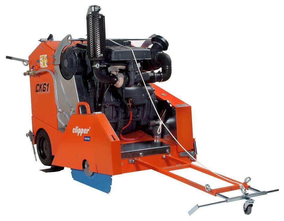
9 2 General description of the CK61 Any modification, which could lead to a change in the original characteristics of the machine, may be done only by Saint-Gobain Abrasives S.A. who shall confirm that the machine is still in conformity with the safety regulations. Saint-Gobain Abrasives S.A. keeps the right of making technical or design modification without prior notification. 2.1 Short description The Floor Saw CK61 you have chosen is used for repair works in concrete and asphalt on highways and runways, for trench sawing or cable loop cutting applications. It can be used for either wet or dry cutting operations. It can be easily transported. All component parts on the CK61 are assembled to a high quality standard, ensuring long life, reliability and a minimum of maintenance. Special types of blades are available for asphalt, green concrete, cured concrete (reinforced or not) as well as for industrial cement flooring. 2.2 Layout Made of jig welded open profile steel, the CK61 is stable but at the same time, easily transportable. The operator s handles (1) can be adjusted to a comfortable position, or removed for transportation. The main operating and safety components are in reach near the operator on the machine panel (2). The engine frame (3) comprises the engine, the feed movement devices, and the hydraulic pump. The front and back pointers (4) allow the operator to make precise cuts easily. The blade guard (5) fully protects the operator and his working environment. It is firmly fixed to the 9
 is composed of a water tank tap (9) and two water nozzles on the blade guard ensuring adequate flow of water to both sides of the blade.")
10 main frame. A small locking handle (25) can be opened to remove the guard to change blades. It can be opened on the front to cut up to a wall. The water cooling system (6) is composed of a water tank tap (9) and two water nozzles on the blade guard ensuring adequate flow of water to both sides of the blade. External water supply has to be used by connecting to the palm coupling. The machine can be lifted using the lifting eyes (7). The pivoting frame, hinged on the rear axle, is supporting the engine, the blade shaft assembly, and the protecting guards. 10 heavy-duty belts drive the blade. The DEUTZ Motor F2L 2011 (8) with 61HP is started with a key. The following picture is showing the main control panel with its components: Two lights are showing the oil pressure (11) and the load of the battery (13). The emergency stop (12) is easy to reach for the operator. You can easily read the temperature of the engine (10) and the working time on the hour meter (15). You can precisely set the depth of cut using the gauge (16), and make many cuts at the same depth using the maximum depth locking system (14). The blade is raised and lowered using the toggle switch (19). The speed of raise and lower is regulated using the control (18). The machine is started using a key (21). The rotational speed of the engine is set with the handle (17), and can be checked with the tachometer (24). To move the machine, you have to take it off the parking position (22). You must then engage the clutch (23) and set the speed forward or backward with the handle (20). 10
11 2.3 Technical data Engine Deutz F3L 2011 (44,9kW/ 61HP) Fuel Diesel complying with the following minimum specifications : DIN EN590 or BS 2869 or ASTM D 975 1D / 2D or NATO Code F-54/f-34/f-44 or XF63 Oil (Motor) Oil complying with the following minimum specifications: API CG4-CH-4 or ACEA E3-96+E4-98 or Deutz DQC II Viscosity recommended : SAE 10W-30 (outside temperature between -20ºC and 30ºC) Oil (Reversing gear box) Fully synthetic oil with a viscosity of SAE 90 Oil (Hydrostatic feed movement) Hydraulic oil with a viscosity equivalent to the one of an automotive oil 20W-50 Oil (Hydraulic system) Under 0 C : VG32 (As per ISO VG DIN51519) HLP32 (As per DIN51519) Cinematic viscosity at 40 C 22, 8-35,2mm 2 /s (csi) 0-30 C : VG46 (As per ISO VG DIN51519) HLP48(As per DIN51519) Cinematic viscosity at 40 C 41, 4-50,6mm 2 /s (csi) Over 30 C : VG68 (As per ISO VG DIN51519) HLP68(As per DIN51519) Cinematic viscosity at 40 C 61, 2-74,8mm 2 /s (csi) Fuel tank 30 L Starter Electric start with key Blade raise system Electro-hydraulic Max. blade diameter 900 mm Bore 25,4 mm Max. cutting depth mm 360 mm Flange diameter 150 mm Blade shaft speed 1180 min -1 Driving belts 10 Machine dimensions 1430x980x1280mm (length x width x height) Weight 760 kg Max. operating weight 810 kg Sound pressure level 100 db (A) following ISO EN Sound energy level 114 db (A) following ISO EN
12 3 Assembly and commissioning Before beginning the work with the CK61, you have to assemble some parts. 3.1 Tool assembly Only use NORTON blades with the CK61. A blade with a maximum diameter of 900 mm can be fitted. All tools used must be selected with regard to their maximum permitted cutting speed for the machine s maximum permitted rotation speed. Before mounting a new blade, switch the machine off. To assemble a new blade, follow these steps: Take the water nozzle off the blade guard. Release the locking handle (25). Take the blade guard (5) off the machine. Untighten the hexagonal screw on the blade shaft with the 19mm wrench. (CAUTION: on the right hand side of the machine, the screw is left-threaded, and the left hand side of the machine, the screw is right-threaded.) Remove the outer flange. Clean the flanges and blade shaft and inspect for wear. Mount the blade on the shaft ensuring that direction of rotation is correct. Wrong direction of rotation blunts the blade quickly. Replace outer blade flange. Tighten screw with 19mm wrench. Reassemble the blade guard and make sure it is securely tighten with the handle (25). Reconnect water nozzle. The blade bore must correspond exactly to the blade shaft. Cracked or damaged bore is dangerous for the operator and for the machine. 3.2 Left or right cut Take the water nozzle off the blade guard. Release the locking handle (25). Take the blade guard (5) off the machine. Disassemble the flange cover from the other side of the machine, and reassemble on the side you used to have the blade guard. Assemble the blade as described in 3.1. on the side where you used to have your flange cover. Reassemble the blade guard making sure that the handle (25) is securely locked. 3.3 Water cooling system Open water-tap (note that handle on water-tap should be in line with water-flow). Ensure that water is flowing freely in the circuit and delivered adequately to both sides of the blade, as insufficient water supply may result in premature failure of the diamond blade. In case of frost, empty the water cooling system. 12
13 3.4 Starting the machine Make sure the blade is raised clear up the ground before starting the machine, and that the clutch is disengaged. Put the throttle lever (17) on the middle position. Insert the key (21) You don t have any operating voltage in position 0. Turn the key clockwise. In position 1, you have operating voltage. Therefore, the oil pressure light (11) and the battery load light should be on. Push the key in and turn further clockwise against the spring pressure. The engine starts in position 3. Release the key as soon as the engine starts. The oil pressure light and the battery load light should go out. Do not actuate the starter for more than 20 seconds. If the engine does not catch, wait a minute then try again. If the motor does not catch after 2 attempts, please refer to the Fault table (see 7.2) to check the problem. The engine temperature meter (10) should remain in the green sector most of the time. It should rarely enter the yellow-green sector. If pointer enters the orange sector, engine is overheating. Turn off the machine, and establish cause from Fault table (see 7.2.). 13
14 4 Transport and Storing Take the following measures in order to transport and store the CK61 securely. 4.1 Securing for transport Before transporting the machine: Remove the blade. Empty the water system and disconnect the machine from the water supply. Raise the guide-a-cut in its upright position. Raise the cutting frame to its highest position. Take the key off the starter. 4.2 Transport procedure The machine can be moved on a flat surface using its wheels. a) Driving the machine Make sure the clutch is disengaged (23), the parking brake is tightened (22) and the speed handle is in middle position. Start the engine. Then engage the clutch and use the speed handle to move the machine backwards or forwards, and to regulate the speed. b) Pushing the machine Disengage the clutch of the machine (23) and the parking brake (22) and push it on the handle (1) without starting the motor. c) Lifting using a crane Make sure that crane can lift the weight of the machine. Use the metal lifting eye (7), located above the engine when lifting the CK61 with a crane. This lifting eye must not be used to lift the saw if the blade is stuck in the cut. CAUTION: Nobody is allowed to go under the machine while it is lifted by the crane. 4.3 Long period of inactivity If the machine is not going to be used for a long period, please take the following measures: Completely clean the machine. Loosen the drive belts. Change the motor oil. Disconnect one of the terminal of the battery so that the battery does not run empty Empty the water system. The storage site must be clean, dry and at a constant temperature. 14
15 5 Operating the CK Site of work Before you start working, please check the following points: Remove from the site anything, which might hinder the working procedure. Make sure the site is sufficiently well lit. Make sure you have a continual adequate view of the working area so you can intervene in the working process at any time. Keep other staff out of the area, so you can work securely. 5.2 Cutting method In this section, you can find instructions to make a straight cut at the desired depth Preparing your cut Before starting the machine, Draw a line on the floor over the cutting length. Make sure you have filled the engine tank with fuel, and the water tank with water, or that you have connected the blade guard to the water supply. No diesel is supplied with the machine. The engine is shipped with oil. Check oil level before starting. Top up if required (see 6.2.). Make sure you have assembled the correct blade as recommended by the manufacturer depending on the material to be worked, the working procedure (dry or wet cut) to be carried out, and the efficiency required. Make sure that the flanges securely hold the diamond blade. Make sure that the blade is not touching the floor before starting the engine. Roll the machine until the blade is over the line. Lower the guide-a-cut so it touches the line. The back guide should also be on this line. Set the speed handle in the middle position, so that if you engage the clutch, the machine will not move unexpectedly. Make also sure that the clutch is disengaged and the parking brake is tightened Cutting the floor You can now start the engine. To make your cut, Lower the pivoting frame until the blade slightly touches the floor. Then set the depth gauge to 0. Open water valve to control the amount of water required for the type of blade, using 15 to 25l/min for wet and 1-2l/min for dry cutting, dust control. Check for minimum water level regularly. Set the rotation of the blade with the throttle lever (17). You can check the speed on the meter (24). Lower blade into the cut. Once the required depth of cut is reached, you can release the parking brake, engage the clutch and use the back and forward handle to regulate speed. Always cut with the machine moving forward, as cutting backwards will damage the blade 15
16 and the blade shaft. Follow the line with the pointer. The feed speed must be adjusted depending on the material being cut, and depth of cut. At the end of the cut, raise the blade out of the cut, switch off the engine and shut-off the water Locking of the cutting depth If you have to make several cuts at the same depth, you can lock the maximum depth your machine will lower to. When you reach the depth for the first time, tighten the locking screw (14) until you reach the stop Setting of the direction Because of the rotation of the blade, the floor saw cannot cut straight in normal operation. Therefore, you have to adjust the direction using the screw (30 below): If you turn the screw clockwise, the floor will turn right. If you turn the screw anti-clockwise, the floor will turn left 16
17 6 Maintenance and service ATTENTION : to perform maintenance on the machine, always switch it off. Always wear a dust protection mask and safety goggles while performing the maintenance of the machine. 6.1 Maintenance of the machine To ensure a long-term quality from the cutting with the CK61, please follow the maintenance plan below: Regular service period Perform at every indicated period After one hour of work Begin of the day During the changing of the tool End of the day Every week Every month After a fault Every year Whole machine Visual control (general aspect, watertightness) Clean Oil (hydrostatic) Control and refill Flange and blade fixing devices Clean Belts tension Control Water hoses and nozzles Clean Hydraulic hose and connectors Control tightness Engine housing Clean Reachable nuts and screws Tighten up Reversing gear box Change oil Hydrostatic feed movement Change oil Grease nipple (pos.34 and 36) Grease Grease nipple (pos. 35) Grease 17

 and turn the screw (33) until the belts are loose.")
18 Adjustment and replacement of the belts After one hour of work, the belts heat and stretch. Therefore, you have to re-tension them. To check the belts, remove the cap 31, and press with normal pressure on the belts. The displacement should be approx. from a belt thickness. To adjust the belts tension, loosen the nut (32) with the 36mm spanner. Then tighten the belts by turning the screw (33) (clockwise: increases belt tension). Then retighten the nut (32). To change the belts, firstly remove the belt guard by untightening the 3 screws. Loose the nut (32) and turn the screw (33) until the belts are loose. Then put new belts on the pulleys and make sure the pulleys are well aligned. Re-assemble the belt guard and re-tension the belts with the screw (33). Then re-tighten the nut (32). Always use a matched set of belts. Do not replace single belts. After controlling or retightening the belts, reassemble the belt guard on the frame of the machine. Grease You must grease the nipples 34, 35 and 36 on both side of the machine regularly with Energrease LS2 BP. 18
.")
19 Oil change for the hydraulic raise/lower system The hydraulic unit (37) is first filled with hydraulic oil BP- Batran HV-68. The old oil can be removed from the unit through the filling hole. To remove the old oil, disassemble the unit and turn it over. Oil change for the reversing gear box Disassemble the gear box (38). Change the oil (SAE 90, fully synthetic, 0,35 litre) using the drain screw on the left side of the gear box. Then reassemble the gear box. Make sure than the belts are correctly tightened. Oil change for the hydrostatic of the feed movement Let the oil drain through the drain screw (40). Re-tighten then this screw. Disassemble the balancing tank (39) and empty it from its remaining oil. Reassemble the balancing tank and fill it with 4,6 litres engine oil 20W50. CAUTION: Please dispose of used oil in a manner that is compatible with the environment. We suggest you to take used oil in a sealed container to your local recycling centre or service station for reclamation. Do not throw it in the trash, pour it on the ground or down in a drain. Cleaning of the machine Your machine will last longer if you clean it thoroughly after each day of work. 6.2 Maintenance of the engine Regular service period Perform operating hour interval Each use First month or 25 hours Every 250 hours Every 500 hours Every 1000 hours Engine oil Check level (5) Change (4) Oil filter Change (2) Fuel filter Change (3) Cooling air zone Check-Clean Clean (dry cut) Air cleaner filter Clean (wet cut) Change the cartridge Valve clearance (1) Check and adjust (only to be done by a DEUTZ-specialist) Fuel filter Replace Belt for alternator Check 19


20 Service place on the engine Oil level check When checking the oil level, the engine must be switched off, and should stand horizontal. Remove the oil dipstick Wipe the dipstick with a non-fibrous, clean cloth. Insert it to the stop and remove it again. Check oil level at the dipstick, and top up if necessary as far as the max. mark Changing oil Allow the engine to warm up and then switch it off. Oil temperature is about 80 C. CAUTION! Risk of scalding from hot oil. Please dispose of used engine oil in a manner that is compatible with the environment. We suggest you to take used oil in a sealed container to your local recycling centre or service station for reclamation. Do not throw it in the trash, pour it on the ground or down in a drain. 20
21 Place an oil tray under the engine. Unscrew the oil drain plug. Drain the oil. Fit the oil drain plug with a new seal ring and tighten it firmly. Pour in new oil up to the MAX. mark on the dipstick. Check the oil level after having run the engine for a short period. Top up if necessary. Changing the oil filter Undo the oil filter cartridge using commercial tool and spin off. Catch any escaping oil. Clean any dirt from the filter carrier sealing surface. Lightly oil the rubber gasket of the new oil filter cartridge. Manually screw in the new cartridge until gasket is flush. Tighten oil filter cartridge with another half-turn. Then check the oil level and the oil pressure. Check the filter cartridge seal for leaks. Changing the fuel filter CAUTION: Keep naked flames away when working on the fuel system. Do not smoke. Close the fuel shut-off valve. Undo the fuel filter cartridge using commercial tool and spin off. Catch any escaping fuel. Clean any dirt from the filter carrier sealing surface. Apply a light film of oil or diesel fuel to rubber gasket of new fuel filter cartridge. Manually screw in the new cartridge until gasket is flush. Tighten fuel filter cartridge with a final half-turn. 21
22 Open the fuel shut-off valve. Check the filter cartridge seal for leaks. Clean strainer of fuel filter CAUTION: Keep naked flames away when working on the fuel system. Do not smoke. Close fuel shut-off valve. Loosen and unscrew the hexagonal nut 1. Remove fuel strainer cover 2 (cover and strainer, one unit) Clean fuel strainer 2 with diesel fuel. Replace if necessary. Place seal 3 in position. Assemble fuel strainer cover 2. Tighten hexagonal screw 1. Check for leaks. Air cleaner If you use the machine in dry cut, you must clean the filter cartridge every day. Otherwise you must clean it when the indicator is showing red (1). To reset the indicator, press on the button. Air cleaner discharge valve Empty dust discharge valve 1 by pressing apart lips of discharge as indicated by arrows. Clean the discharge slot from time to time. Remove any caked dirt by pressing together upper section of valve. 22
23 Filter cartridges Undo the clip fasteners 1. Take off the hood 2 and remove cartridge 3. Clean the cartridge, and replace it at least once a year. Clean cartridge 3 using compressed air (max. 5 bar). Blow out from inside to outside (or in difficult cases, tap out, taking care not to damage cartridge, or wash according to manufacturer s instructions.) Gaskets on filter cartridge can become damaged through regular removal and replacement. Check paper filter (light showing through) and gaskets for damage. Replace if necessary. After five cleaner services or after two years at latest, replace the safety cartridge 4 (never clean) by undoing the hexagonal nut 5 and removing the cartridge 4. Install the new cartridge 3, replace hood 2 and do up the clip fasteners 1. Alternator belts Slacken off bolts 1, 2 and 3. Adjust alternator 4 in direction of the arrow by turning the bolt 3 until correct belt tension is achieved. Retighten the bolts 1, 2 and 3. To change the belts, Slacken off bolts 1, 2 and 3. Adjust the alternator 4 in the direction of arrow by turning the bolt 3. Remove and replace the belt. Adjust alternator 4 against direction of arrow by turning bolt 3, until correct belt tension is achieved. Retighten bolts 1, 2 and 3. Control the valve clearance Only a DEUTZ specialised dealer check the valve clearance. You also have to let a specialised dealer check your engine every 1000 hours of operation. 23
24 7 Faults: causes and cures 7.1 Fault-finding procedures Should any fault occur during the use of the machine, turn it off. Let only qualified staff make any intervention other than the one described in the previous section. 7.2 Trouble-shooting guide Trouble Possible source Resolution Engine does not start or is difficult to start. Engine fires but stops again as soon as the crank is disengaged. Engine lacks power. Engine becomes excessively hot. Engine stops by itself during regular operation. Fuel quality not as per operating manual Incorrect oil class or quality Temperature too low Battery defective or discharged Stronger fault No oil pressure Cylinder head temperature too high Stronger fault Tank run dry Air cleaner clogged Speed control lever does not remain in the selected position Stronger fault Air cleaner clogged Oil level too high or too low Belt to alternator broken or untightened Tank run dry Air filter restricted No oil pressure Stronger fault Change quality of diesel Change quality of oil Use cold start oil Change or recharge battery Contact nearest engine maintenance centre Check the oil level Check cooling air passage Contact nearest engine maintenance centre Add fuel Clean or replace air filter Prevent speed control from moving Contact nearest engine maintenance centre Clean or replace air filter Check oil level Check or change belt Add fuel Clean or replace air filter Check the oil level Contact nearest engine maintenance centre 24
25 7.3 Customer service When ordering spare parts, please mention: The serial number (seven digits). The code of the part. The exact denomination. The number of parts required. The delivery address. Please indicate clearly the means of transportation required such as "express" or "by air". Without specific instructions, we will forward the parts through the means which seem appropriate to us and but which is not always the quickest way. Clear instructions will avoid problems and faulty deliveries. If not sure, please send us the defective part. In the case of a warranty is claim, the part must always be returned for evaluation. Spare parts for the engine can be ordered with the manufacturer of the engine or with their dealer, which is often quicker and cheaper. This machine has been manufactured by Saint-Gobain Abrasives S.A. 190, Bd. J.F. Kennedy L BASCHARAGE Grand-Duché de Luxembourg. Tel. : Fax :
26 Guarantee can be claimed and technical support obtained from your local distributor where machines, spare parts and consumables can be ordered as well: Benelux and France: From Saint-Gobain Abrasives in the Grand-Duché de Luxembourg Free telephone numbers: Belgium : France: Holland: sales.nlx@saint-gobain.com Germany Saint-Gobain Diamond Products GmbH Birkenweg 45-49, D WESSELING Tel : (02236) Fax : (02236) sales.ngg@saint-gobain.com Spain Saint-Gobain Abrasivos S.A. C/. Verneda del Congost s/n Pol.Ind. El Pedregar E MONTMELÓ (Barcelona) Tel: Fax: Comercial.sga-apa@saint-gobain.com Hungary Saint-Gobain Abrasives KFT. Banyaleg Utca 60B H-1225 BUDAPEST Tel: Fax: nortonbp@axelero.hu United Kingdom Saint-Gobain Abrasives Ltd. Doxey Road Stafford ST16 1EA Tel : Fax : nortondiamonduk@saint-gobain.com Italy Saint-Gobain Abrasivi S.p.A. Via per Cesano Boscone, 4 I CORSICO-MILANO Tel: Fax: Norton.edilizia@saint-gobain.com Austria Saint-Gobain Abrasives GmbH Telsenberggasse 37, A-5020 SALZBURG Tel: Fax: office@sga.net Poland Saint-Gobain Diamond Products Sp.zO.O. AL. Krakowska 110/114 PL WARSZAWA Tel: Tel/Fax: norton-diamond@wp.pl Czech Republic Norton Diamantove Nastroje Sro Vinohrdadska 184 CS PRAHA 3 Tel: Fax: norton.diamonds@komerce.cz 26
27 27

28 SAINT-GOBAIN ABRASIVES 190, Bd. J. F. Kennedy L-4930 BASCHARAGE LUXEMBOURG Tel.: Fax:
CS1 P13 OPERATING INSTRUCTIONS
 CS1 P13 OPERATING INSTRUCTIONS 2 Declaration of conformity The undersigned manufacturer: SAINT - GOBAIN ABRASIVES S.A. 190, BD J.F. KENNEDY L- 4930 BASCHARAGE Declares that this product: Floor saw (Code):
CS1 P20 OPERATING INSTRUCTIONS
 CS1 P20 OPERATING INSTRUCTIONS 2 Declaration of conformity The undersigned manufacturer: SAINT - GOBAIN ABRASIVES S.A. 190, BD J.F. KENNEDY L- 4930 BASCHARAGE Declares that this product: Floor saw (Code):
CSB1 P20 OPERATING INSTRUCTIONS
 CSB1 P20 OPERATING INSTRUCTIONS 2 Declaration of conformity The undersigned manufacturer: SAINT - GOBAIN ABRASIVES S.A. 190, BD J.F. KENNEDY L- 4930 BASCHARAGE Declares that this product: Floor saw: CSB1
CS 451 P13 OPERATING INSTRUCTIONS
 CS 451 P13 OPERATING INSTRUCTIONS 2 Declaration of conformity The undersigned manufacturer: SAINT-GOBAIN ABRASIVES S.A. 190, BD J.F. KENNEDY L- 4930 BASCHARAGE Declares that this product: Floor saw: CS
Beton Trowel nv INSTRUCTION MANUEL SLAB SAW BTCS500 - GEBABEBB BBRUBEBB BNP FORTIS: ING: BE BE
 INSTRUCTION MANUEL SLAB SAW BTCS500 BBRUBB 1/20 Use this guide along with the parts lists attached to locate and identify components of your trowel. When ordering replacement parts, be sure to provide
CS1 P13. OPERATING INSTRUCTIONS Translation of the original instructions
 CS1 P13 OPERATING INSTRUCTIONS Translation of the original instructions VERS.2017.06.12 2 VERS.2015.07.23 Declaration of conformity The undersigned manufacturer: SAINT - GOBAIN ABRASIVES S.A. 190, BD.
The CLIPPER Solutions
 The CLIPPER Solutions 93 C51 6,5 Hp Ø 350mm 76kg Petrol Compact, robust and highly manoeuvrable machines designed for both wet and dry cutting of concrete and asphalt. Features Cutting depth adjustment
HOT WASHER MODEL NO: KING 125 OPERATION & MAINTENANCE INSTRUCTIONS PART NO: LS1009
 HOT WASHER MODEL NO: KING 125 PART NO: 7320170 OPERATION & MAINTENANCE INSTRUCTIONS LS1009 INTRODUCTION Thank you for purchasing this Hot Washer. This machine is a portable, high pressure power washer,
AU DU PONT DE LUTTRE BRUSSELS BELGIUM PHONE: FAX: OPERATING MANUAL. Electric Fully Automatic Floor Saw FS 1218 EX
 AU DU PONT DE LUTTRE 74-1190 BRUSSELS BELGIUM PHONE: 322 34 83 162 FAX: 322 34 83 136 OPERATING MANUAL Electric Fully Automatic Floor Saw FS 1218 EX 2 Important information before you start! When the machine
muck-truck It doesn t cost the earth to move it! OWNERS & OPERATIONS INSTRUCTION MANUAL
 muck-truck It doesn t cost the earth to move it! PEDESTRIAN DUMPER MKIII OWNERS & OPERATIONS INSTRUCTION MANUAL CONGRATULATIONS! And thank you for purchasing a new muck-truck. We have done our utmost to
OPERATION AND MAINTENANCE MANUAL SERIES HIGH GRASS MOWER FT
 S.p.A. OPERATION AND MAINTENANCE MANUAL SERIES HIGH GRASS MOWER www.hscmsc.co.uk CONTENTS INTRODUCTION IDENTIFICATION AND TECHNICAL CHARACTERISTICS PACKING AND TRANSPORT SAFETY RULES AND LIMITS ON USE
1100W PORTABLE GENERATOR
 1100W PORTABLE GENERATOR MODEL NO: G1200 PART NO: 8010110 OPERATION & MAINTENANCE INSTRUCTIONS LS0312 INTRODUCTION Thank you for purchasing this CLARKE 1100W Portable Generator. Before attempting to use
GENERATOR MODEL NO: FG3000 OPERATION & MAINTENANCE INSTRUCTIONS PART NO: LS0609
 GENERATOR MODEL NO: FG3000 PART NO: 8857700 OPERATION & MAINTENANCE INSTRUCTIONS LS0609 INTRODUCTION Thank you for purchasing this CLARKE Generator. Before attempting to use this product, please read this
ENGINE DRIVEN 3 FULL TRASH PUMP
 ENGINE DRIVEN 3 FULL TRASH PUMP MODEL NO: PF75 PART NO: 7230165 OPERATION & MAINTENANCE INSTRUCTIONS ORIGINAL INSTRUCTIONS LS0117 ISS 2 INTRODUCTION Thank you for choosing this Clarke Pump. The function
GENERATOR MODEL NO: FG2500 OPERATION & MAINTENANCE INSTRUCTIONS PART NO: LS0114
 GENERATOR MODEL NO: FG2500 PART NO: 8857727 OPERATION & MAINTENANCE INSTRUCTIONS LS0114 INTRODUCTION Thank you for purchasing this CLARKE Generator. Before attempting to use this product, please read this
1/4 Die Grinder. Please read and fully understand the instructions in this manual before operation. Keep this manual safe for future reference
 Please dispose of packaging for the product in a responsible manner. It is suitable for recycling. Help to protect the environment, take the packaging to the local amenity tip and place into the appropriate
DIAMOND CONCRETE SAW MODEL CC1800XL P R O D U C T S OPERATOR S MANUAL. February Part #
 DIAMOND P R O D U C T S OPERATOR S MANUAL CONCRETE SAW MODEL CC1800XL February 2007 Part #1801038 Intentionally Blank GENERAL SAFETY WARNINGS AND PRECAUTIONS PERSONAL SAFETY Read and understand all operating
5.5KVA GENERATOR MODEL NO: PG6500DVES OPERATION & MAINTENANCE INSTRUCTIONS PART NO: LS0616
 5.5KVA GENERATOR MODEL NO: PG6500DVES PART NO: 8857810 OPERATION & MAINTENANCE INSTRUCTIONS LS0616 INTRODUCTION Thank you for purchasing this CLARKE 5.5KVA Generator. Before attempting to use this product,
20 TONNE HYDRAULIC PRESS MODEL NO: CSA20FBT
 20 TONNE HYDRAULIC PRESS MODEL NO: CSA20FBT PART NO: 7614058 OPERATION & MAINTENANCE INSTRUCTIONS WARNING: Read these instructions before using the press GC0516 INTRODUCTION Thank you for purchasing this
INSTALLATION, OPERATION AND MAINTENANCE INSTRUCTIONS
 INSTALLATION, OPERATION AND MAINTENANCE INSTRUCTIONS Contents Section 1. General Observations... 2 2. Operation... 4 3. Control During Operation... 5 4. Trouble Shooting... 6 5. Maintenance... 7 Please
Beton Trowel nv INSTRUCTION MANUAL SLAB SAW BTCS500 - GEBABEBB BBRUBEBB BNP FORTIS: ING: BE BE
 INSTRUCTION MANUAL SLAB SAW BTCS500 BBRUBB 1/20 Use this guide along with the parts lists attached to locate and identify components of your saw. When ordering replacement parts, be sure to provide the
MTD OHV Series FORM NO B. jqa=mêççìåíë=^âíáéåöéëéääëåü~ñí= =p~~êäêωåâéå= =déêã~åó
 MTD OHV Series J15 FORM NO. 769-08890B jqa=mêççìåíë=^âíáéåöéëéääëåü~ñí= =p~~êäêωåâéå= =déêã~åó 4 11 19 27 35 43 51 58 65 72 79 87 96 104 112 119 126 134 141 148 155 162 171 179 188 197 206 213 221
3 Ton Trolley Jack. Please read and fully understand the instructions in this manual before operation. Keep this manual safe for future reference.
 Please dispose of packaging for the product in a responsible manner. It is suitable for recycling. Help to protect the environment, take the packaging to the local amenity tip and place into the appropriate
SIP Direct Drive Oil-Lube Air Compressors - Operating & Maintenance Instructions
 SIP Direct Drive Oil-Lube Air Compressors - Operating & Maintenance Instructions Please read and fully understand the instructions in this manual before operation. Keep this manual safe for future reference.
* * * * 8 Maintenance Plan 10.1,10.2, ,4 7.1/7.2/7.3
 Maintenance 8 Maintenance Plan * * * * * GB 10.1,10.2,10.3 6.1 12.2 12.1 11.2 12.1 7,4 7.1/7.2/7.3 1.1/1.2/1.3 3.1/3.2/3.3/3.4/4.1/11.1 5.1 5.2 4.2 5.1 5.2 2.1/2.2/2.3/2.4/2.5/2.6/4.1 Item Designation
3KVA DUAL VOLTAGE GENERATOR MODEL NO: PG3800DV
 3KVA DUAL VOLTAGE GENERATOR MODEL NO: PG3800DV PART NO: 8857815 OPERATION & MAINTENANCE INSTRUCTIONS LS1016 INTRODUCTION Thank you for purchasing this CLARKE 3KVA Dual Voltage Generator. Before attempting
CROMMELINS COMPACTORS
 CROMMELINS COMPACTORS OPERATION & INSTRUCTION MANUAL Thank you for your selection of a CROMMELINS Compactor. This Operation Manual explains its use, installation, checking and maintenance. We highly recommend
WARNING! Ensure that there are no naked flames around the product! Do not smoke while filling fuel and oil!
 Engine Oil and Fuel Engine Operation This product is equipped with a 4 stroke engine. Before operation you have to add proper fuel and engine oil. DO NOT MIXTURE THEM! 1. Place the product on a stable,
Tooling Assistance Center
 Safeguards are designed into this application equipment to protect operators and maintenance personnel from most hazards during equipment operation. However, certain safety precautions must be taken by
GENERATOR MODEL NO: FG3005 OPERATION & MAINTENANCE INSTRUCTIONS PART NO: LS0413
 GENERATOR MODEL NO: FG3005 PART NO: 8857707 OPERATION & MAINTENANCE INSTRUCTIONS LS0413 INTRODUCTION Thank you for purchasing this CLARKE Generator. Before attempting to use this product, please read this
CK31 SPARE PARTS LIST
 CK31 SPARE PARTS LIST 1 Spare parts list POS. Art.Nr. DESCRIPTION TYPE(*) 1001 ENGINE SUPPORT FRAME S 1002.1 310034109 SCREW M16X80 LEFT THR. DIN 931 GALV. S 1002.2 310034110 SCREW M16X80 RIGHT THR. DIN
DYNAPAC CONCRETE EQUIPMENT RAMIRENT. BG70 Power Floats INSTRUCTIONS & SPARE PARTS CATALOGUE BG70 - IS ENG
 DYNAPAC CONCRETE EQUIPMENT INSTRUCTIONS & SPARE PARTS CATALOGUE BG70 Power Floats BG70 - IS - 10682 - ENG SAFETY INSTRUCTIONS - MACHINES SUBMITTED : Powered with : Electric, Pneumatic, Petrol or Diesel
HEAVY DUTY TROLLEY JACK. Operation Manual
 HEAVY DUTY TROLLEY JACK 4T Operation Manual Make sure to read and fully understand the instruction manual before using this product and keep the manual properly 1 General Description Product Description
Dry installed pump type LANDY BTP.
 OPERATION & MAINTENANCE MANUAL Dry installed pump type LANDY BTP. Landustrie Sneek BV Pieter Zeemanstraat 6 Tel. 0031 515-486888 P.O. BOX 199 Fax. 0031 515-412398 NL-8600 AD Sneek info@landustrie.nl The
1200W INVERTER GENERATOR
 1200W INVERTER GENERATOR MODEL NO: IG1200 PART NO: 8877070 OPERATION & MAINTENANCE INSTRUCTIONS LS0117 INTRODUCTION Thank you for purchasing this CLARKE 1200W Inverter Generator. Before attempting to use
Preventive maintenance 4
 00 Series Preventive maintenance Preventive maintenance periods Use the procedures in this chapter to maintain your engine in accordance with the preventive maintenance schedule. Check the periods given
80 Litre Suction Oil Drainer With Inspection Chamber
 Please dispose of packaging for the product in a responsible manner. It is suitable for recycling. Help to protect the environment, take the packaging to the local amenity tip and place into the appropriate
AIR-COOLED DIESEL GENERATOR OWNERʼS MANUAL. This manual contains important safety information. TDG2500E TDGW7000E TDG7000SE TDG4500E
 AIR-COOLED DIESEL GENERATOR OWNERʼS MANUAL This manual contains important safety information. TDG2500E TDGW7000E TDG7000SE TDG4500E TDG8000-3 TDG7000SE-3 TDG7000E TDG8000E TDGW7000SE TDG7000E3 TDGW8000E
Operating instructions ErgoPack 600 E
 Operating instructions ErgoPack 600 E Operation of the device is only permitted if the operating instructions have been carefully read and understood before use! Declaration of conformity EU declaration
AG-HA-2500N GASOLINE GENERATOR
 AG-HA-2500N GASOLINE GENERATOR OWNER S MANUAL BEFORE OPERATING THIS EQUIPMENT PLEASE READ THESE INSTRUCTIONS CAREFULLY (I)WARNING 1. Read the operator s instruction manual. 2. Attention! Exhaust gases
PETROL DRIVEN POWER WASHER
 WARNING: Read these instructions before using the machine PETROL DRIVEN POWER WASHER MODEL NO: TIGER 2500/2900 PART NO: 7320055/7320056 OPERATION & MAINTENANCE INSTRUCTIONS LS0513 INTRODUCTION Thank you
COLLECTOR 37 USER MANUAL
 COLLECTOR 37 USER MANUAL A B E F C D H 2 G ENGLISH INTRODUCTION POWERBOSS,Inc. leaders in the production of sweeping machines, are pleased to welcome you as an owner of the Collector 37 sweeper machine.
OPERATIONS MANUAL LEVER CHAIN HOIST
 OPERATIONS MANUAL LEVER CHAIN HOIST IMPORTANT SAFETY INFORMATION Please read, understand and follow all safety information contained in these instructions prior to the use of this hoist. Retain these instructions
Air Compressor. Operating & Maintenance Instructions 1110 ENGINE DRIVEN - 1 -
 Air Compressor ENGINE DRIVEN Operating & Maintenance Instructions 1110-1 - Read these safety instructions before using the equipment. INTRODUCTION Thank you for purchasing this Clarke portable compressor.
Maintenance of Pleasureboat Diesel Engine GM Series
 Maintenance of Pleasureboat Diesel Engine GM Series.Safety Precaution for Inspection )Battery Fluid Battery fluid is diluted sulfuric acid. It can blind you if it gets in your eyes, or burn your skin.
WARNING: Read these instructions before using the machine GENERATOR MODEL NO: IG3500F PART NO: OPERATION & MAINTENANCE INSTRUCTIONS
 WARNING: Read these instructions before using the machine GENERATOR MODEL NO: IG3500F PART NO: 8877100 OPERATION & MAINTENANCE INSTRUCTIONS ORIGINAL INSTRUCTIONS LS0217 INTRODUCTION Thank you for purchasing
WARNING Carefully Read These Instructions Before Use
 DO NOT RETURN THIS SPRAYER TO STORE Call: 1-800-950-4458 Backpack Sprayer Use and Care Manual Manufactured for Northern Tool + Equipment Co., Inc. WARNING Carefully Read These Instructions Before Use Model
Finishing Mower Estate 72
 Finishing Mower Estate 72 Owners/Operators Manual & Spare Parts List Issue Date: October 2011 1 Introduction Your FIELDMASTER Estate 72 Finishing Mower has been designed to do a range of work to your satisfaction.
OPERATION & MAINTENANCE INSTRUCTIONS
 WARNING Read the instructions before using the machine PETROL DRIVEN POWER WASHER MODEL NO: TIGER1700 PART NO: 7320054 OPERATION & MAINTENANCE INSTRUCTIONS LS0511 2 INTRODUCTION Thank you for purchasing
Table of Contents. Safety symbols... 3 Assembly 6. Operation Maintenance Troubleshooting 11. Storage. 12. Notes. 13
 Table of Contents Safety symbols... 3 Assembly 6 Operation... 8 Maintenance... 10 Troubleshooting 11 Storage. 12 Notes. 13 2 Safety Information Attention; this machine can be dangerous! All operators should
USE and MAINTENANCE INSTRUCTION MANUAL AZ3 HTE2 AZ3 HTE2 HVLP GRAVITY. SPRAY GUN Series. en it fr es pt de se
 USE and MAINTENANCE INSTRUCTION MANUAL AZ3 HTE2 AZ3 HTE2 HVLP GRAVITY SPRAY GUN Series en it fr es pt de se TECHNICAL DATA Technical AZ3 HTE2 AZ3 HTE2 HVLP 1.0 80 180 1.3 10-15HTE 140 200 240 1.5 2.0 160
Medium and high pressure pumps
 Screw pumps Medium and high pressure pumps Installation and Start-up Instruction This instruction is valid for all standard high pressure pumps: E4, D4 and D6 Contents Page Pump identification 2 Installation
PETROL GENERATOR PGH2200, PGH3000, PGH6500 OWNER S MANUAL FOR YOUR SAFETY PLEASE READ THESE INSTRUCTIONS CAREFULLY AND RETAIN THEM FOR FUTURE USE.
 PETROL GENERATOR OWNER S MANUAL PGH2200, PGH3000, PGH6500 FOR YOUR SAFETY PLEASE READ THESE INSTRUCTIONS CAREFULLY AND RETAIN THEM FOR FUTURE USE. WARRANTY GENERATOR SAFETY This generator is covered by
A408 GB. Pneumatic oil and diesel pumps 1:1
 03 594 A408 GB Pneumatic oil and diesel pumps 1:1 G Operating instructions for Pneumatic oil and diesel pump 1:1 Contents 1. General details 2 1.1 Intended use 2 1.2 Design and functional description 2
PETROL GENERATOR SPG2200, SPG3000, SPG6500 OWNER S MANUAL FOR YOUR SAFETY PLEASE READ THESE INSTRUCTIONS CAREFULLY AND RETAIN THEM FOR FUTURE USE.
 PETROL GENERATOR OWNER S MANUAL SPG2200, SPG3000, SPG6500 FOR YOUR SAFETY PLEASE READ THESE INSTRUCTIONS CAREFULLY AND RETAIN THEM FOR FUTURE USE. WARRANTY This generator is covered by a 24 month warranty
Cordless Screwdriver
 ENGLISH Cordless Screwdriver MODEL 6796D MODEL 6796FD MODEL 6797D MODEL 6797FD MODEL 6798D MODEL 6798FD 00260 I N S T R U C T I O N M A N U A L WARNING: For your personal safety, READ and UNDERSTAND before
PowerSafe Two Wheel Tractors
 PowerSafe Two Wheel Tractors Manufactured by BCS S.p.A. Models 710 728 738 740 750 Operating Instructions Before commissioning the machine, read operating instructions and observe warning and safety instructions.
LP 9-20 E PAC. Crowder Supply Co., Inc Roslyn St., Commerce City, CO Toll Free:
 LP 9-20 E PAC www.crowdersupply.com Toll Free: 888-883-5144 ATLAS COPCO CONSTRUCTION TOOLS AB 2006-10 NACKA SWEDEN No. 3392 5033 01 a www.atlascopco.com 1 English INTRODUCTION... 2 SAFETY INSTRUCTIONS...
Standard Valves Series Globe Valves Series Angle Valves Series Way-Valves
 Installation, Operation, Maintenance Instructions Standard Valves Series 035 000 Globe Valves Series 031 000 Angle Valves Series 033 000 3-Way-Valves 1 GENERAL INFORMATION These instructions are designed
Instruction Manual. Vibratory Plate Compactor
 Instruction Manual Vibratory Plate Compactor Model VPC45R Model VPC65R Model VPC85R Model VPC95R Table of Contents 1. INTRODUCTION...1 2. SAFETY...1-2 3. SPECIFICATIONS.....2 4. APPLICATION.. 2 5. CHECK
Instruction Model 18537
 Instruction 738-556 Model 18537 LIMITED WARRANTY H. D. Hudson Manufacturing Company warrants to the original purchaser only that this product will continue to function as intended if used in accordance
SERVICE MANUAL (2)
") Terra 128B - 132B SERVICE MANUAL 146 0721 000(2)2003-04 INDEX GENERAL INFORMATION 3 MACHINE LIFTING 3 MACHINE TRANSPORTATION 3 OTHER AVAILABLE MANUALS 3 SAFETY - ACCIDENT PREVENTION 4 GENERAL SAFETY RULES
Terra 128B - 132B SERVICE MANUAL 146 0721 000(2)2003-04 INDEX GENERAL INFORMATION 3 MACHINE LIFTING 3 MACHINE TRANSPORTATION 3 OTHER AVAILABLE MANUALS 3 SAFETY - ACCIDENT PREVENTION 4 GENERAL SAFETY RULES
STIGA TORNADO 51 S 51 SE PRO 51 S
 STIGA TORNADO 51 S 51 SE PRO 51 S 8211-0225-09 SVENSKA S 1 2 3 1. 2. ADD FULL FULL ADD ADD FULL 0,15 l. 3. LS 45 4. XTE 60 3x 5. LS 45 6. XTE 60 STOP I H 7. 8. 2 S SVENSKA 9. 10. 11. 12. LS 45 0,75 mm
Operating and Installation Instructions Diaphragm Vacuum Pumps and Compressors
 Operating and Installation Instructions Diaphragm Vacuum Pumps and Compressors Type range: UN813.3ANI UN813.4ANI UN813.3ANDCB UN813.4ANDCB UN813.5ANI Fig. 1: UN813.3ANI Fig. 2: UN813.4ANI You have selected
GL Ludemann Y-Strainers
 GL Ludemann Y-Strainers Installation, Operation and Maintenance Manual English Issue 1-03/2014 - Page 1/7 GENERAL These instructions are for installing, operation and maintenance of Y-strainers fabricated
Pressure relief valve
 Pressure relief valve Operating manual Series DHV 712 Version BA-2015.10.20 EN Print-No. 300 510 TR MA DE Rev001 ASV Stübbe GmbH & Co. KG Hollwieser Straße 5 32602 Vlotho Germany Phone: +49 (0) 5733-799-0
LDG6000SA DIESEL GENERATOR OWNERS MANUAL
 LDG6000SA DIESEL GENERATOR OWNERS MANUAL BEFORE OPERATING THIS EQUIPMENT PLEASE READ THESE INSTRUCTIONS CAREFULLY Preface Thank-you for purchasing this generator. This operation manual contains information
2 Ton - 50 Ton Bottle Jack
 Please dispose of packaging for the product in a responsible manner. It is suitable for recycling. Help to protect the environment, take the packaging to the local amenity tip and place into the appropriate
Instruction Manual. Vibratory Reversible Plate Compactor
 Instruction Manual Vibratory Reversible Plate Compactor Model VPR300 Model VPR400 Foreword This manual has been written to help you operate your Vibratory Reversible Compactor safely. It is intended primarily
OPERATOR S MANUAL AND PARTS LIST PETROL LINE TRIMMER - THPLT-A. Spares & Support:
 OPERATOR S MANUAL AND PARTS LIST PETROL LINE TRIMMER - THPLT-A Spares & Support: 01793 333212 www.thehandy.co.uk Before use please read & understand this manual, paying particular attention to the safety
Not for Reproduction. BILLY GOAT AERATOR Owner's Manual AE401, AE401H, AE401H5T Replacement Parts. AE Owner s Manual TINE ROW KIT TINE KIT P/N
 BILLY GOAT AERATOR Owner's Manual AE401, AE401H, AE401H5T Replacement Parts TINE ROW KIT Complete tine row set for replacement of one complete row of tines. Includes mounting plates, spacer, and all hardware.
Northern Sales & Distribution Centre
 User Manual Industrial Door Northern Sales & Distribution Centre The Door Centre, Discovery Park, Crossley Road, Stockport, SK4 5BW /indupart /indupart /indupart /company/indupart-ltd Foreword This user
PETROL POWER WASHER MODEL NO: PLS195, PLS265 OPERATION & MAINTENANCE INSTRUCTIONS PART NO: , LS0616
 PETROL POWER WASHER MODEL NO: PLS195, PLS265 PART NO: 7330360, 7330365 OPERATION & MAINTENANCE INSTRUCTIONS LS0616 INTRODUCTION Thank you for purchasing this CLARKE Petrol Power Washer. Before attempting
Light condition and operation Windshield glass condition Wiper blade condition Paint condition and corrosion Fluid leaks Door and hood lock condition
 GENERAL CHECKS Engine Compartment The following should be checked regularly: Engine oil level and condition Transmission fluid level and condition Brake fluid level Clutch fluid level Engine coolant level
APT14 Automatic Pump Trap Installation and Maintenance Instructions
 6120250/7 IM-P612-04 ST Issue 7 APT14 Automatic Pump Trap Installation and Maintenance Instructions 1 Product information 2 Operation 3 Installation Closed loop steam systems only 4 Commissioning 5 Maintenance
CALIFORNIA TRIMMER MOWER MAINTENANCE MANUAL
 CALIFORNIA TRIMMER MOWER MAINTENANCE MANUAL 2 Table of Contents Section 1: General Information Page Handle Assembly Instructions 4 Maintenance All Models 6 Oil Change Procedures All Models 9 Height Adjustment
Maintenance Information
 51984144 Edition 6 May 2014 Air Paving Breaker MX60 & MX90 Maintenance Information Save These Instructions Product Safety Information WARNING Failure to observe the following warnings, and to avoid these
OPERATING MANUAL C-1350 CABLE PUSHER. Copyright 2003 by CBS Products (KT), Ltd
, Ltd") CBS Products (KT), Ltd, Pillings Road, Oakham, Rutland, LE15 6QF. UK Telephone: +44(0)1572723665 Fax: +44(0)1572 756006 E-Mail: sales@cbsproducts.com Website:www.cbsproducts.com OPERATING MANUAL C-1350
CBS Products (KT), Ltd, Pillings Road, Oakham, Rutland, LE15 6QF. UK Telephone: +44(0)1572723665 Fax: +44(0)1572 756006 E-Mail: sales@cbsproducts.com Website:www.cbsproducts.com OPERATING MANUAL C-1350
MODEL HD99 HYDRAULIC ONE MAN TOWABLE EARTHDRILL
 DO NOT THROW AWAY IMPORTANT MANUAL MODEL HD99 HYDRAULIC ONE MAN TOWABLE EARTHDRILL Operators Manual GROUND HOG, INC. P.O.BOX 290 San Bernardino, CA. 92402 Phone (909) 478-5700 Fax (909) 478-5710 E-mail:
3.25 Ton Heavy Duty Floor Jack
 Please dispose of packaging for the product in a responsible manner. It is suitable for recycling. Help to protect the environment, take the packaging to the local amenity tip and place into the appropriate
Edition Manual Chapter Page Workshop Manual, Stiga Park 4 Hydraulic system 8
 2008-05-19 Workshop Manual, Stiga Park 4 Hydraulic system 8 The charge pump (1) and the main pump (2) are integrated into one unit, the hydraulic pump (C) which is located separat in front of the engine.
LAWN MOWER OWNER S MANUAL
 LAWN MOWER OWNER S MANUAL Woodies SKU: 1153279 & 1153280 CAUTION: Read and follow all Safety Rules and Instructions before operating this equipment Thank you for choosing our Gasoline Lawnmower. 1 To ensure
Starting up hydraulic systems
 General / Installation A hydraulic system that operates economically, safely, and trouble-free requires careful planning, as well as proper installation and start-up. Conscientious maintenance has a considerable
TILLOTSON LTD., CLASH INDUSTRIAL ESTATE, TRALEE, CO. KERRY, IRELAND PHONE: FAX:
 TILLOTSON LTD., CLASH INDUSTRIAL ESTATE, TRALEE, CO. KERRY, IRELAND PHONE: +353 66 7121911 FAX: +353 66 7124503 e-mail: sales@tillotson.ie SERIES SERVICE MANUAL INTRODUCTION The gasoline engine industry
Index. 1. Important safety instructions Overview of the lift Installation instructions Operation instructions 8-9
 2 Index 1. Important safety instructions 4-5 1.1 Safety Warnings 1.2 Qualified personnel 1.3 Safety 1.4 Warning signs 2. Overview of the lift 6 2.1 General descriptions 2.2 Technical data 2.3 Construction
HYDRAULIC PALLET TRUCK MODEL NO: PT540M/BM/CM & PT685BM/CM PART NO: , , , ,
 HYDRAULIC PALLET TRUCK MODEL NO: PT540M/BM/CM & PT685BM/CM PART NO: 7631700, 7631705, 7631710, 7631715, 7631720 OPERATION & MAINTENANCE INSTRUCTIONS LS0316 INTRODUCTION Thank you for purchasing this CLARKE
Operating and Maintenance Manual. for. HADEF overhead crane. as jointed crane TA
 5.52.714.00.1.0 Edition 03.2004 GB Operating and Maintenance Manual for HADEF overhead crane as jointed crane TA Subject to changes. 1 HADEF Table of Contents 1 General Page 3 2 Product description Page
Operating Manual TYROLIT ( ) A Company within the SWAROVSKI Group
 A Company within the SWAROVSKI Group") HYCON HRS RING SAW Operating Manual www.tyrolit.com.au info.au@tyrolit.com 1300 TYROLIT (897 654) A Company within the SWAROVSKI Group Important Clean after use DURING OPERATION WATER AND SLURRY CAN GET
HYCON HRS RING SAW Operating Manual www.tyrolit.com.au info.au@tyrolit.com 1300 TYROLIT (897 654) A Company within the SWAROVSKI Group Important Clean after use DURING OPERATION WATER AND SLURRY CAN GET
Safety, Operation and Maintenance Instructions For Long & Short Nose Upholstery Air Stapler (NS10 & NS11)
") Safety, Operation and Maintenance Instructions For Long & Short Nose Upholstery Air Stapler (NS10 & NS11) Important: Drop 3 drops of oil into the stapler air inlet BEFORE first use. See page 2. Please
Safety, Operation and Maintenance Instructions For Long & Short Nose Upholstery Air Stapler (NS10 & NS11) Important: Drop 3 drops of oil into the stapler air inlet BEFORE first use. See page 2. Please
Repair Manual 11/99 PS-34. Page 1
 Repair Manual /99 PS-4 Page Table of contents Index Technical Data page Special tools 4 Repair instructions, general 0 Chain brake 6 0 Centrifugal clutch 8 0 Oil pump 9-04 Ignition system - 0 Starting
HOFFMANN POWER PRODUCTS PARTS LIST 2014
 HOFFMANN POWER PRODUCTS PARTS LIST 2014 VIBRATORY PLATE COMPACTOR ALL PARTS ARE SUBJECT TO STANDARD HOFFMANN TERMS AND CONDITIONS OF SALE 2010 Replacement parts are not manufactured, sold or warranted
TC07 TURF CUTTER Operating Instructions
 TC07 TURF CUTTER Operating Instructions Before commissioning the machine, read operating instructions and observe warning and safety instructions. Tracmaster Ltd CAMON TC07 Turf Cutter Manufacturer Details
Engine oil. Introduction. Warning and indicator lights WARNING
 Engine oil Introduction In this section you ll find information about: Warning and indicator lights Engine oil specifications Engine oil capacities Checking the engine oil level and adding oil Engine oil
VBK 2596/12E/RSF. Thickness and Width Gauge for Strip and Profile. Operating- & Service Instructions. (with lateral guide rollers)
") Thickness and Width Gauge for Strip and Profile (with lateral guide rollers) VBK 2596/12E/RSF Operating- & Service Instructions erstellt am 5.2.1998 freigegeben am Bemerkungen Rev.01 Seiten:16 Name: Rietdorf
Thickness and Width Gauge for Strip and Profile (with lateral guide rollers) VBK 2596/12E/RSF Operating- & Service Instructions erstellt am 5.2.1998 freigegeben am Bemerkungen Rev.01 Seiten:16 Name: Rietdorf
Version 1.4 Operating instructions Czech Republic
 Version 1.4 Operating instructions Czech Republic Please check updates of operating instructions at www.rotomotor.cz, that your engine has still the best care. (can happen important changes that will lead
by Eder Maschinenbau GmbH
 by Eder Maschinenbau GmbH GB Owner's Manual Contents Symbols 3 Technical data 3 Field of use 4 Safety regulations 4 Fuel and filling the tank 5 Engine oil 5 Slings and rope guide 5 Safety instruction for
DISASSEMBLY AND ASSEMBLY INSTRUCTIONS FOR LIQUID RING VACUUM PUMPS
 (Rev. 2.0_10-2010) DISASSEMBLY AND ASSEMBLY INSTRUCTIONS FOR LIQUID RING VACUUM PUMPS TRVK 2003 to 5003 TRSK 2005 to 5005 INTRODUCTION These instructions are for the maintenance staff in case of repair
FB 300 FB 450 FB 700 USER MANUAL
 FB 300 FB 450 FB 700 USER MANUAL 2 USE SWEPAC FB 300 / FB 450 / FB 700 are used to pack ballast under foundations, in connection with road building, in trenches, etc. On account of the forward/reverse
USE and MAINTENANCE INSTRUCTION MANUAL W-300 W-300 WB LPH-300 GRAVITY. SPRAY GUN Series. en it fr es pt de se
 USE and MAINTENANCE INSTRUCTION MANUAL W-300 W-300 WB LPH-300 GRAVITY SPRAY GUN Series en it fr es pt de se TECHNICAL DATA High T.E.C. series Nozzle_Needle set Combination W-300 WB W-300 W-300-081G 0.8
Maintenance Information
 16573370 Edition 2 February 2014 Air Grinder 99V Series Maintenance Information Save These Instructions Product Safety Information WARNING Failure to observe the following warnings, and to avoid these