See the PDF attachment B Preliminary Work.pdf for removal of the intake manifold and valve cover.
|
|
|
- Frank Parrish
- 5 years ago
- Views:
Transcription
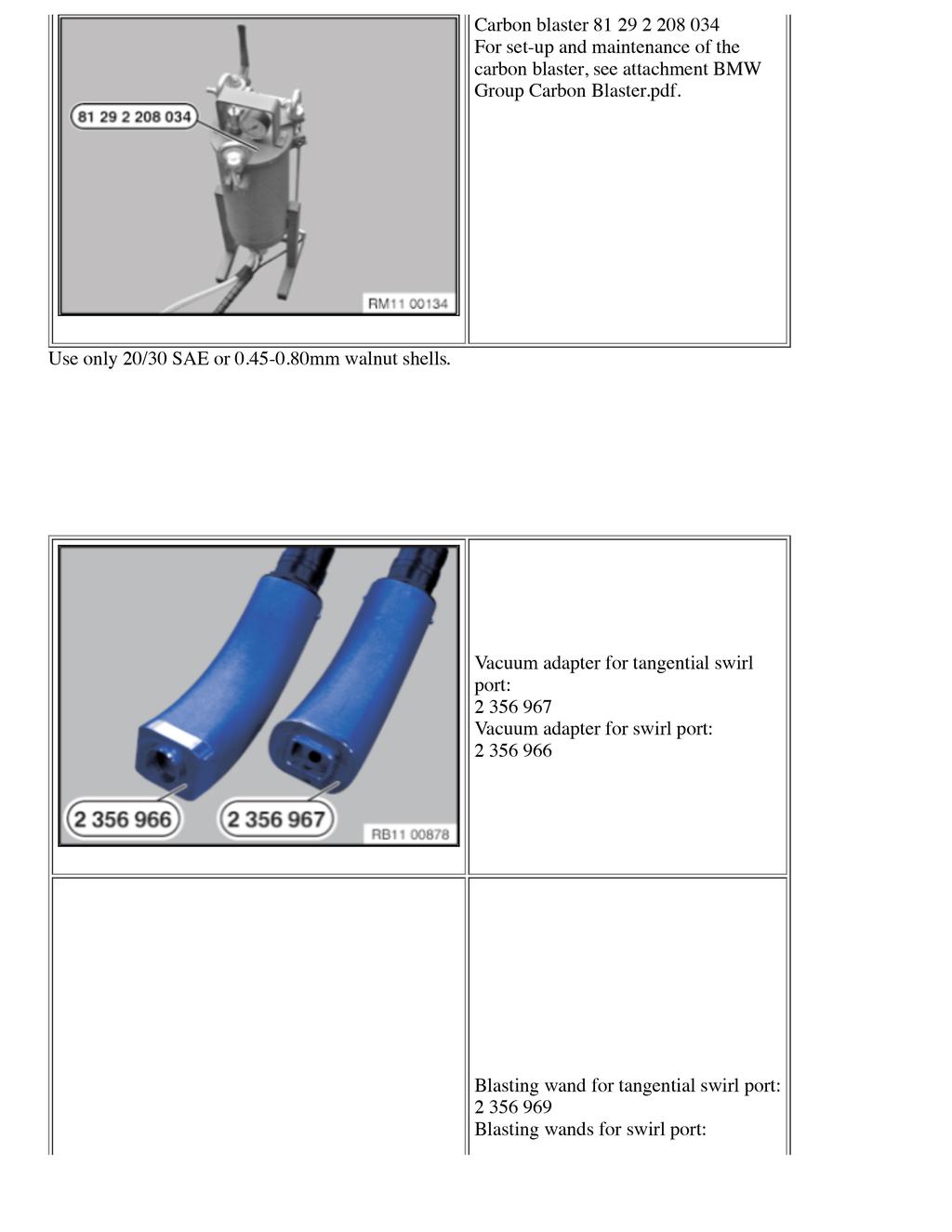
1 SI B Engine April 2014 Technical Service SUBJECT Diesel Intake Carbon Cleaning MODEL E90 (3 Series Sedan) With M57Y engine (335d) SITUATION The Service Engine Soon light is on and the engine may run roughly. Possible Fault Codes stored: 3FF1 air mass sensor 4595 rough controller Cylinder 6 459B rough controller Cylinder rough controller Cylinder rough controller Cylinder rough controller Cylinder 2 459C rough controller Cylinder 1 CAUSE Based on the above stored Fault Code profile, there is excessive carbon buildup in the intake system. PROCEDURE The intake valves in both the swirl and tangential ports will be cleaned, including chemical cleaning of the intake manifold. See the PDF attachment B Preliminary Work.pdf for removal of the intake manifold and valve cover. Important! Wear safety goggles and protective gloves. When working on the oil, coolant or fuel circuit, you must protect the alternator from contamination. Cover the alternator with suitable materials. Failure to comply with this procedure may result in alternator malfunction. It is essential to adhere to conditions of absolute cleanliness when carrying out repair work on the fuel system. Do not allow any dirt particles or foreign bodies to get into the system. Use only fluff-free cloths.
 found in ISTA/D.")
2 Recycling: Remove all traces of dirt contamination before dismantling lines or separate components. Seal all fuel system openings with protective caps. Catch and dispose of escaping fuel. Observe country-specific waste disposal regulations. This procedure supersedes Repair Instruction RA , Cleaning cylinder head intake channels and intake plenum (E90US, M57T2) found in ISTA/D. SPECIAL TOOLS REQUIRED Alignment pin (used for securing cylinder 1 TDC). Socket for crankshaft hub (used for advancing the pistons/valves to TDC).

3

: Bend wand 968 (1) straight (2).")

4 with straight outlet with lateral outlet Reference SI B for specific details on the carbon blaster attachments for the M57Y engine. Modifying wand (before first use): Bend wand 968 (1) straight (2). This will ensure the wand bottoms out inside the swirl port. Insert wand 968 into the swirl port adapter 966 at one inch and mark off the exposed end (1) with a paint marker. Do not pull the wand past this mark while cleaning!
 to avoid scratching or gouging")

.")
5 Set of professional hooks (1) (purchased separately) 6-piece set PN2KKV3 Grainger Professional Hook Set shown as an example Grind down the tips of the picks (1) to avoid scratching or gouging the aluminum in the swirl ports. CLEANING THE INTAKE MANIFOLD Note: Unless it is necessary for another reason, replacing the intake manifold is not required when performing this procedure. Note: Picture shows M57T2 Europe Release the three screws (1). Remove the throttle valve from the exhaust-gas recirculation valve. Release the four screws for the exhaust-gas recirculation valve (2).

 and then prying at the opposite")
6 Remove the swirl flap actuator (1). Carefully pry out the swirl flap linkage, starting at the actuator end (1) and then prying at the opposite end (2).
 from the intake manifold before cleaning. These parts will be reinstalled.")

7 Remove the screws for the swirl flap (1). Repeat for the remaining five swirl flaps. Slide out the swirl flap (1). Repeat for the remaining five swirl flaps. Note: Remove all intake seals (1). Replace these with new gaskets when reinstalling. Remove all bolts, seals and fasteners (2) from the intake manifold before cleaning. These parts will be reinstalled. Recommended procedure for Manifold Cleaning Send the intake manifold and swirl flaps to an engine machine shop or equivalent automotive parts repair/reconditioning (i.e., radiator repair shop) facility for ultrasonic cleaning or a suitable, mild solvent parts cleaning hot tank process. Ensure that all ports, swirl and tangential flaps are toughly cleaned.
. Use an appropriate parts cleaner (1) and spray clean the inner bore of the EGR valve (2).")
8 Use an appropriate parts cleaner (1) and spray clean the throttle plate and throttle bore (2). Note: Do not spray any cleaner onto the electrical components of the valve. Installation note: Clean the sealing surfaces. Replace the gasket (1). Use an appropriate parts cleaner (1) and spray clean the inner bore of the EGR valve (2). Note: Scrape away any excessive buildup before spraying with parts cleaner. Do
.")
9 not spray any cleaner onto the electrical components of the valve. Valve Cover Cleaning Wipe out excessive carbon buildup in the swirl ports of the valve cover (1). CARBON BLASTING CYLINDER HEAD Remove the protective cap in the direction of the arrow. Installation note: Reinstall the protective cap with some grease.


10 Crank the engine at the central bolt using in the direction of rotation until the piston of the 1st cylinder is in the TDC setting. Secure the crankshaft in the TDC setting with special tool Important! Do not turn the engine back. Special tool must be removed before starting the engine. Make note of the rotation of the camshafts (2) and the position of the camshaft lobes (1) when cylinder 1 is at TDC. The position of the camshaft lobes for the next cylinder to be cleaned must be in the TDC position for that next cylinder. After each cleaning, the engine must be cranked over to the TDC of the next cylinder to be cleaned (firing order ). Note: Do not crank the engine backward! (A) Exhaust cam (E) Intake cam
. Do not overfill the cylinder!")

 on the blasting tool (2).")
11 Remove the top from the carbon blaster (1) and fill with walnuts (2). Do not overfill the cylinder! Fill the cylinder until the material is approximately 30mm (1) below the air inlet port on the side of the cylinder. Reinstall the top. Close the main valve (1) on the blasting tool (2). Connect the compressed air (3). Note: Operating pressure 6-8 bar Screw together the necessary blasting

 to vacuum adapter 2 356 967 (2) and direct towards the tangential swirl port of the 1st cylinder.")
. When the trigger is moved to stage one (2), only compressed air flows through the blasting wand.")
12 wand (968, 969 or 970) (1) and actuator (2). There are slotted markings on the front section of the wands (969 and 970). During the blasting process, only pull the wands out of the vacuum adapter until the mark becomes visible. Wand 968 will have a painted mark (after the wand has been modified by the center). Tangential ports: Connect the vacuum cleaner (1) to vacuum adapter (2) and direct towards the tangential swirl port of the 1st cylinder. Open the main valve on the blasting tool and switch the vacuum cleaner on. Insert the blasting wand (3) into the adapter (2). Open the actuator valve (4). After the wand is inserted into the adapter: Unlock trigger (1). When the trigger is moved to stage one (2), only compressed air flows through the blasting wand. In stage two (3) (trigger is fully pressed), granulate is added (blasting process). Alternate between stage one and two when blasting. This will ensure the ports are not overfilled with blasting media.
 first and apply walnuts for about 5-10 seconds.")

13 Swirl Ports: Insert adapter (1) into the swirl port as shown. Attach a shop vacuum to the large port on the adapter (2). Use adapter (straight outlet) first and apply walnuts for about 5-10 seconds. Switch to the (lateral outlet) adapter and apply another cleaning for about seconds. Remove the 966 adapter. Move both wands up and down and rotate during cleaning to expose the entire swirl port to the walnuts. The cut-away photo shows carbon buildup in the swirl port. After this initial cleaning, there will still be carbon deposits in the tight channel that bends into the bottom of the swirl port (1).

14 Use the pick set to loosen up the remaining carbon buildup. The carbon is soft, and the feel of the pick will be different once the carbon is scraped off the swirl port. After scraping with picks, apply another blast of walnuts to the swirl port, first with adapter for seconds and then switch to adapter and blast for another seconds. Repeat the blasting/pick scraping again, if needed, until the swirl port and intake valve is clean. Before cleaning, the swirl port and valve (1) will look similar to the photo (borescope used).


15 There will still be some carbon buildup (1) in the tighter areas of the swirl port after the initial cleaning. This is when the pick set is used to scrape/loosen this carbon. Use the walnut blaster/scraping/walnut blaster combination until the swirl port
.")

16 and valve are clean (1). It may take more than one application to complete. Note: Do not leave any used walnut shells in the swirl port (1). The excess shells can be cleared out with compressed air sprayed from the walnut blaster wand (stage one). Remove locking pin from the flywheel and continue to the next cylinder for cleaning. Reassemble the cleaned intake manifold and manifold components, and install the EGR valve and throttle valve onto the intake. Install the valve cover and intake manifold and check the vehicle after repairs for leaks (air or fuel). Connect to ISTA/D and clear faults. Test drive vehicle and recheck for fault codes and repair/correct as necessary.
17 PARTS INFORMATION Note: Unless it is necessary for another reason, replacing the intake manifold is not required when performing this procedure. Part Number Description Quantity O-ring, camshaft position sensor Valve cover gasket Gasket, intake Gasket, intake Gasket, EGR valve to intake Grommet, pressure sensor O-ring, throttle to EGR valve O-ring, leakage lines O-ring, injector Washer, injector Washer, fuel return line Torx bolt M10 X ASA Bolt with circlip M12 x 1.5 x 39 1 WARRANTY INFORMATION Covered under the terms of the BMW New Vehicle/SAV Limited Warranty or the BMW Certified Pre-Owned Program. Defect Code: Labor Operation: Labor Allowance: Description: Refer to KSD2 and Refer to KSD2 and Refer to KSD Performing vehicle test (with vehicle diagnosis system checking faults) Connect an approved battery charger/power supply(indicated in KSD2 as Charging battery ) Removing and installing/sealing the cylinder head cover (includes removing and installing the intake manifold)
18 and FRU Work time for disassembling, assembling the intake manifold and cleaning the applicable removed parts. Also included is carbon-cleaning the valves of the 6 cylinders. Labor operation code is a Main labor operation. If you are using a Main labor code for another repair, use the Plus code labor operation instead. If the microfilter casing is already removed to perform another repair, use the associated labor operation instead. Refer to KSD2 for the corresponding flat rate unit (FRU) allowance. Enter the Chassis Number, which consists of the last 7 digits of the Vehicle Identification Number (VIN). Click on the Search button, and then enter the applicable flat rate labor operation in the FR code field. Even though work time labor operation code ends in 000, it is not considered a Main labor operation. Also, since the work time FRU allowance to be claimed is specified, a separate punch time is not required. Sublet Cleaning the Intake Manifold Sublet Code 3 Sublet amount; see below Reimbursement for third-party repair Invoice this eligible sublet work on the repair order at the actual cost charged with no handling or markup. The sublet amount must also include any discounts or allowances. Itemize the sublet amount in the claim comment section. ATTACHMENTS View PDF attachment B110314_1174_Vacuum_System_Arrangement_(M57T2TOP_SCR). View PDF attachment B110314_Preliminary_Work. View PDF attachment B110314_BMW_Group_Carbon_Blaster. [ Copyright 2014 BMW of North America, Inc. ]
https://webista.bmw.com/webista/show?id= &lang=enus&print=1
 Page 1 of 12 REP-REP-RAE70M57T2-1112800 Cleaning cylinder heat intake channels and intake plenum (E70US, M57T2) VIN: Vehicle: X' / E70 / off-road vehicle / X5 35d x / M57 / USA / left-hand drive / AUT
https://www.bmwtis.net/tiscode/cgi-bin/bulletin.aspx?sie_path=/tsb/bulletins/htm_store/216...
 Page 1 of 5 SI B12 33 14 Engine Electrical Systems March 2015 Technical Service This Service Information bulletin supersedes SI 12 33 14 dated December 2014. designates changes to this revision SUBJECT
DISASSEMBLY. Engine. CAUTION: Remove the cylinder heads before removing the crankshaft. Failure to do so can result in engine damage.
 303-01A-1 DISASSEMBLY Engine Special Tool(s) Remover, Crankshaft Vibration Damper 303-101 (T74P-3616-A) Special Tool(s) Crankshaft Socket 303-674 303-01A-1 Remover, Crankshaft Vibration Damper 303-773
Please read this Service Information bulletin in its entirety, the content has been completely updated.
 Page 1 of 6 SI B01 09 14 Warranties September 2014 Warranties This Service Information bulletin supersedes SI B01 09 14 dated August 2014. Please read this Service Information bulletin in its entirety,
SPECIFICATIONS TEST AND ADJUSTMENT SPECIFICATIONS SPECIFICATIONS ENGINE FD620D, K SERIES
 TEST AND ADJUSTMENT Engine Oil Pressure Sensor Activates............................... 98 kpa (14.2 psi) Oil Pressure While Cranking (Minimum).......................... 28 kpa (4 psi) Oil Pressure.....................................
SPECIFICATIONS TEST AND ADJUSTMENT SPECIFICATIONS SPECIFICATIONS ENGINE FD620D, K SERIES
 ENGINE FD620D, K SERIES SPECIFICATIONS SPECIFICATIONS TEST AND ADJUSTMENT SPECIFICATIONS Engine Oil Pressure Sensor Activates............................... 98 kpa (14.2 psi) Oil Pressure While Cranking
FOOTWELL MODULE: LIMITED WARRANTY EXTENSION TO 8 YEARS/125,000 MILES
 Page 1 of 7 SI B01 20 16 Warranties August 2016 Technical Service FOOTWELL MODULE: LIMITED WARRANTY EXTENSION TO 8 YEARS/125,000 MILES MODEL E70 (X5 xdrive 35d) (M75Y Engine) Model produced 8/13/2009 to
Removing and installing/replacing high-pressure pump (N47) (32 FRU)
 (32 FRU)") Page 1 of 6 BMW Group - AIR: 2018-08-23 / 09:17 Retailer: 31519/02 Model: X3 2.0sd Vehicle identification number: WJ57494 Development code: E83 Model code: PE21 Lead type: PE21 Order number: - Repair instruction
Page 1 of 6 BMW Group - AIR: 2018-08-23 / 09:17 Retailer: 31519/02 Model: X3 2.0sd Vehicle identification number: WJ57494 Development code: E83 Model code: PE21 Lead type: PE21 Order number: - Repair instruction
1.8L & 2.2L 4-CYL Article Text 1998 Subaru Impreza
 1.8L & 2.2L 4-CYL Article Text 1998 Subaru Impreza ARTICLE BEGINNING 1995-98 ENGINES Subaru - 1.8L & 2.2L 4-Cylinder 1995-97: Impreza (1.8L) 1995-98: Impreza (2.2L), Legacy (2.2L) * PLEASE READ THIS FIRST
Excluding the E70 with diesel engines, X5 M, X6 M and the BMW Alpina B6 and BMW Alpina B7 models with xdrive
 SI B27 03 15 Intermediate and Special Transmission August 2015 Technical Service SUBJECT Vibration or Shudder from Driveline when Accelerating from a Stop MODEL E70 (X5) E71 (X6) E84 (X1) F01 (7 Series
dated December SUBJECT BMW Maintenance Program: 12-Volt Battery Replacement Measure MODEL
 SI B61 30 14 General Electrical Systems January 2015 Technical Service This Service Information bulletin supersedes SI B61 30 14 dated December 2014. designates changes to this revision SUBJECT BMW Maintenance
Service Bulletin Published by Sudden Service, Inc.
 Service Bulletin Published by Sudden Service, Inc. Volume 18 / Number 2 / February 1, 2018 Louisville, Mississippi Preventative Maintenance (PM) Requirements for Diesel Engines Equipped With EPA Tier 4
REMOVAL & INSTALLATION
 REMOVAL & INSTALLATION NOTE: For reassembly reference, label all electrical connectors, vacuum hoses and fuel lines before removal. Also place mating marks on engine hood and other major assemblies before
Lab #5 4-Cylinder Single Overhead Cam Engine Dissection
 Engr 3 Mission College Faculty: Kate Disney TA: Andrew Dina Lab #5 4-Cylinder Single Overhead Cam Engine Dissection Equipment: 4-Cylinder Mazda 16 Valve SOHC 92 (Manual Transmission) Ratchet with 2 and
First check if a Recall Campaign label with a code number 666 is already attached to the B-pillar.
 SI B11 21 14 Engine December 2014 Technical Service PERFORM THE PROCEDURE OUTLINED IN THIS SERVICE INFORMATION ON ALL AFFECTED VEHICLES BEFORE CUSTOMER DELIVERY OR THE NEXT TIME THEY ARE IN THE SHOP FOR
Engine. Special Tool(s) Compressor, Piston Ring 303-D032 (D81L-6002-C) or equivalent. Compressor, Valve Spring (T93P-6565-AR)
 Compressor, Piston Ring 303-D032 (D81L-6002-C) or equivalent. Compressor, Valve Spring (T93P-6565-AR)") SECTION 303-01C: Engine 5.4L (4V) 2009 Mustang Workshop Manual ASSEMBLY Procedure revision date: 12/12/2008 Engine Special Tool(s) Compressor, Piston Ring 303-D032 (D81L-6002-C) or equivalent Compressor,
SECTION 303-01C: Engine 5.4L (4V) 2009 Mustang Workshop Manual ASSEMBLY Procedure revision date: 12/12/2008 Engine Special Tool(s) Compressor, Piston Ring 303-D032 (D81L-6002-C) or equivalent Compressor,
Weistec M156/M159 ENGINE
 Weistec M156/M159 ENGINE Oil / Air Separator System Installation Guide 2007-2011 S63 AMG 2007-2011 ML63 AMG 2007 R63 AMG 2007-2008 CLK63 AMG 2008 CLK63 Black Series 2007-2011 CLS63 AMG 2008-Present C63
WEIAND STREET WARRIOR INTAKE MANIFOLD P/N s 8125, 8125P, 8126, & 8126P SMALL BLOCK CHEVROLET
 APPLICATIONS: WEIAND STREET WARRIOR INTAKE MANIFOLD P/N s 8125, 8125P, 8126, & 8126P 262-400 SMALL BLOCK CHEVROLET INSTALLATION INSTRUCTIONS The P/N 8125 & 8126 WEIAND STREET WARRIOR series intake manifolds
N63 Valve Stem Seal Tool Kit Part #: AGA-N63-VSK-K
 N63 Valve Stem Seal Tool Kit Part #: AGA-N63-VSK-K Problem: Your BMW is smoking due to bad valve stem seals. Old valve stem seals harden over time and no longer provide a proper seal between the seal and
ASSEMBLY. Engine. Special Tool(s) Installer, Crankshaft Vibration Damper (T74P-6316-B) Special Tool(s)
 Installer, Crankshaft Vibration Damper (T74P-6316-B) Special Tool(s)") 303-01A-1 ASSEMBLY Engine Special Tool(s) Tensioner, Timing Chain 303-571 (T97T-6K254-A) Special Tool(s) 303-01A-1 Installer, Crankshaft Vibration Damper 303-102 (T74P-6316-B) Holding Tool, Camshaft Sprocket
303-01A-1 ASSEMBLY Engine Special Tool(s) Tensioner, Timing Chain 303-571 (T97T-6K254-A) Special Tool(s) 303-01A-1 Installer, Crankshaft Vibration Damper 303-102 (T74P-6316-B) Holding Tool, Camshaft Sprocket
FOOTWELL MODULE (FRM): LIMITEDWARRANTY EXTENSION INCREASED TO 10 YEARS/156,000. Complaint
: LIMITEDWARRANTY EXTENSION INCREASED TO 10 YEARS/156,000. Complaint") Page 1 of 9 BMW Group - AIR: 2018-08-22 / 07:35 Dealer: 32711/06 Model: - Development code: - Model code: - Lead type: - Order number: - Service Information Bulletin FOOTWELL MODULE (FRM): LIMITEDWARRANTY
Page 1 of 9 BMW Group - AIR: 2018-08-22 / 07:35 Dealer: 32711/06 Model: - Development code: - Model code: - Lead type: - Order number: - Service Information Bulletin FOOTWELL MODULE (FRM): LIMITEDWARRANTY
CAUTION. Fuel Injection Pump, In-Line, Spill Port Timing
 Page 4 of 22 Rotate the crankshaft counterclockwise, as viewed from the front of the engine, to approximately 40 degrees before TDC. Both the RQV and RQV-K governor require the shutdown lever to be in
ENGINE TUNE-UP INSPECTION OF ENGINE COOLANT INSPECTION OF ENGINE OIL INSPECTION OF BATTERY. INSPECTION OF AIR FILTER (Paper Filter Type)
") ENGINE MECHANICAL - Engine Tune-Up EM-17 ENGINE TUNE-UP INSPECTION OF ENGINE COOLANT (See steps 1 and 2 on page CO-4) INSPECTION OF ENGINE OIL (See steps 1 and 2 on page LU-5) INSPECTION OF BATTERY (See
ENGINE MECHANICAL - Engine Tune-Up EM-17 ENGINE TUNE-UP INSPECTION OF ENGINE COOLANT (See steps 1 and 2 on page CO-4) INSPECTION OF ENGINE OIL (See steps 1 and 2 on page LU-5) INSPECTION OF BATTERY (See
 Page 1 of 21 303-01C Engine 5.4L (3V) 2009 F-150 REMOVAL Procedure revision date: 03/26/2009 Cylinder Head Special Tool(s) 3 Jaw Puller 303-D121 or equivalent Compressor, Valve Spring 303-1039 Holding
DISASSEMBLY. Engine. Special Tool(s) Locking Tool, Camshaft Phaser Sprocket Special Tool(s)
 Locking Tool, Camshaft Phaser Sprocket Special Tool(s)") 303-01B-1 DISASSEMBLY Engine Special Tool(s) Remover, Crankshaft Rear Slinger 303-514 (T95P-6701-AH) Special Tool(s) 303-01B-1 Locking Tool, Camshaft Phaser Sprocket 303-1046 Remover, Crankshaft Rear Seal
303-01B-1 DISASSEMBLY Engine Special Tool(s) Remover, Crankshaft Rear Slinger 303-514 (T95P-6701-AH) Special Tool(s) 303-01B-1 Locking Tool, Camshaft Phaser Sprocket 303-1046 Remover, Crankshaft Rear Seal
1989 Nissan 300ZX. 3.0L V6 - VIN [H] & 3.0L V6 TURBO - VIN [C] 1989 Engines - 3.0L & 3.0L Turbo V6
![1989 Nissan 300ZX. 3.0L V6 - VIN [H] & 3.0L V6 TURBO - VIN [C] 1989 Engines - 3.0L & 3.0L Turbo V6](/thumbs/95/124411779.jpg "1989 Nissan 300ZX. 3.0L V6 - VIN [H] & 3.0L V6 TURBO - VIN [C] 1989 Engines - 3.0L & 3.0L Turbo V6") INTAKE MANIFOLD Removal 1. Release fuel system pressure. Disconnect battery and drain cooling system. Disconnect vacuum and coolant lines attached to intake manifold and label accordingly. Remove throttle
INTAKE MANIFOLD Removal 1. Release fuel system pressure. Disconnect battery and drain cooling system. Disconnect vacuum and coolant lines attached to intake manifold and label accordingly. Remove throttle
2002 Mustang Workshop Manual
 Page 1 of 13 SECTION 303-01B: Engine 4.6L (2V) 2002 Mustang Workshop Manual REMOVAL Procedure revision date: 01/02/2003 Cylinder Heads Special Tool(s) Remover, Crankshaft Vibration Damper 303-009 (T58P-6316-D)
Special tools required:
 11 12 100 Removing and installing/sealing cylinder head (S54) Special tools required: 11 4 400 12 1 120 Remove both exhaust manifolds. Remove intake filter housing with air-mass flow sensor. Remove cylinder
Engine. Special Tool(s) Adapter for (T97T-6256-A) Adapter for (T97T-6256-D)
 Adapter for (T97T-6256-A) Adapter for (T97T-6256-D)") SECTION 303-01A: Engine 4.0L SOHC 2009 Mustang Workshop Manual ASSEMBLY Procedure revision date: 05/10/2010 Engine Special Tool(s) Adapter for 303-564 303-578 (T97T-6256-A) Adapter for 303-577 303-576
SECTION 303-01A: Engine 4.0L SOHC 2009 Mustang Workshop Manual ASSEMBLY Procedure revision date: 05/10/2010 Engine Special Tool(s) Adapter for 303-564 303-578 (T97T-6256-A) Adapter for 303-577 303-576
This Service Information bulletin supersedes SI B dated September 2014.
 Home Model Map Contact My Profile Logout Technical Information System Home Service Information Reference Information OSS Tools and Equipment Home Service Bulletins General Search Notification System Make
A. Perform a vacuum gauge test to determine engine condition and performance.
 ENGINE REPAIR UNIT 2: ENGINE DIAGNOSIS, REMOVAL, AND INSTALLATION LESSON 2: ENGINE DIAGNOSTIC TESTS NOTE: Testing the engine s mechanical condition is required when the cause of a problem is not located
Holley GM BBC Single-Plane EFI Intake Manifold Kits
 Holley GM BBC Single-Plane EFI Intake Manifold Kits 300-561 Oval Port, 4150 Flange 300-562 Oval Port, 4500 Flange 300-563 Rectangular Port, 4150 Flange 300-564 Rectangular Port, 4500 Flange INSTALLATION
Service Bulletin
 Service Bulletin 16-008 October 4, 2016 04983 Version 3 High Pressure Fuel Pump Chirps (Supersedes 16-008, dated April 30, 2016, to revise the information highlighted in yellow) AFFECTED VEHICLES Year
FOOTWELL MODULE (FRM): LIMITED WARRANTY EXTENSION INCREASEDTO 10 YEARS/156,000. Complaint
: LIMITED WARRANTY EXTENSION INCREASEDTO 10 YEARS/156,000. Complaint") Page 1 of 9 BMW Group - AIR: 2018-08-18 / 16:21 Dealer: 32711/06 Model: - Development code: - Model code: - Lead type: - Order number: - Service Information Bulletin FOOTWELL MODULE (FRM): LIMITED WARRANTY
Page 1 of 9 BMW Group - AIR: 2018-08-18 / 16:21 Dealer: 32711/06 Model: - Development code: - Model code: - Lead type: - Order number: - Service Information Bulletin FOOTWELL MODULE (FRM): LIMITED WARRANTY
Intake Components 1117
 Item Part Number Description 1 W705654 Bolt 2 N807309 Bolt (2 req'd) 3 9F460 Bracket 4 N807071 Bolt (5 req'd) 5 9A448 Intake manifold (upper) 6 9E498 Vacuum harness 7 9F792 Fuel injection supply manifold
Cylinder Head Assembly: Service and Repair Replacing the Cylinder Head and Gasket
 2002 Volvo V40 L4-1.9L Turbo VIN 29 B4204T3 Copyright 2009, ALLDATA 10.10 Page 1 Cylinder Head Assembly: Service and Repair Replacing the Cylinder Head and Gasket Cylinder Head/Gasket, Replacing Special
TECHNICAL INSTRUCTIONS FOR SAFETY RECALL ALE VALVE SPRING AND LASH ADJUSTER REPLACEMENT GS 350: IS 350:
 TECHNICAL INSTRUCTIONS FOR SAFETY RECALL ALE VALVE SPRING AND LASH ADJUSTER REPLACEMENT GS 350: 2007 2008 IS 350: 2006 2008 I. OPERATION FLOWCHART Verify Vehicle Eligibility 1. Check the VIN range. 2.
2000 Econoline Workshop Manual. 3. Install the upper intake manifold. 2. NOTE: Tighten the bolts in two stages.
 2. NOTE: Tighten the bolts in two stages. Tighten the bolts in the sequence shown. Stage 1: Tighten to 2 Nm (18 lb-in). Stage 2: Tighten to 10 Nm (89 lb-in). 3. Install the upper intake manifold. Position
PERFORM THE PROCEDURE OUTLINED IN THIS SERVICE INFORMATION ON ALL AFFECTED VEHICLES THE NEXT TIME THEY ARE IN THE SHOP FOR MAINTENANCE OR REPAIRS.
 Page 1 of 8 SI B23 01 07 Manual Transmission June 2007 Technical Service PERFORM THE PROCEDURE OUTLINED IN THIS SERVICE INFORMATION ON ALL AFFECTED VEHICLES THE NEXT TIME THEY ARE IN THE SHOP FOR MAINTENANCE
DISASSEMBLY Procedure revision date: 11/22/2001
 Page 1 of 31 Evan Groenke From: Daniel Lelovic [dlelovic@rogers.com] Sent: May 8, 2005 12:06 PM To: 'Evan Groenke' Subject: 2.5 L Engine Disassembly SECTION 303-01B: Engine 2.5L 2000 Contour/Mystique Workshop
WEIAND INTAKE MANIFOLD P/N 7550 SMALL BLOCK CHEVROLET 3x2 BBL
 WEIAND INTAKE MANIFOLD P/N 7550 SMALL BLOCK CHEVROLET 3x2 BBL INTAKE MANIFOLD INSTALLATION INSTRUCTIONS 199R10703 APPLICATIONS: The P/N 7550 WEIAND intake manifold is designed for Holley 3x2 BBL, model
Zoom and Print Options
 Vehicle» Engine, Cooling and Exhaust» Engine» Cylinder Head Assembly» Service and Repair» Procedures» Removal Cylinder Heads http://repair.alldata.com/alldata/article/display.action?componentid=65&itypeid=376&nonstandardid=682956&vehicleid=45317&windowname=maina
 Page 1 of 7 1965 Ford Mustang 4.7L Eng VIN A Base Service Manual: 221", 260", 289" V8 ENGINES Print Date: ENGINE NOTES 1962-65 COOLANT LOSS OR WATER PUMP & FRONT COVER CORROSION CORRECTION: May be caused
<4D5> ENGINE Click on the applicable bookmark to selected the required model year
 ENGINE 11B-2 ENGINE General Information GENERAL INFORMATION 11100010339 Items 4D56 Total displacement m 2,477 Bore x Stroke mm 91.1 x 95.0 Compression ratio 21 Combustion chamber Camshaft
Cylinder head, removing and
 Page 1 of 35 15-2 Cylinder head, removing and installing Note: Replace cylinder head bolts. Always replace self-locking nuts, bolts as well as gaskets and O-rings. After installing a replacement cylinder
WEIAND X-CELerator Intake Manifold P/N 7516
 WEIAND X-CELerator Intake Manifold P/N 7516 351C FORD, 2V CYLINDER HEADS INSTALLATION INSTRUCTIONS APPLICATIONS: The P/N 7516 X-CELerator intake manifold is designed for square-bore carburetor applications
Removal and Installation of the DD15 and DD16 Cylinder Head April Removal of the DD15 and DD16 Cylinder Head
 4 102-12 1 4 102-12 SUBJECT DATE Removal and Installation of the DD15 and DD16 Cylinder Head April 2012 Additions, Revisions, or Updates Publication Number / Title Platform Section Title Change DDC-SVC-MAN-0081
EXHAUST GAS RECIRCULATION (EGR) SYSTEM (4A FE)
 SYSTEM (4A FE)") ENGINE EG121 EXHAUST GAS RECIRCULATION (EGR) SYSTEM (4AFE) EGR SYSTEM INSPECTION 1. INSPECT AND CLEAN FILTER IN EGR VACUUM MODULATOR (a) Remove the cap and filter. (b) Check the filter for contamination
ENGINE EG121 EXHAUST GAS RECIRCULATION (EGR) SYSTEM (4AFE) EGR SYSTEM INSPECTION 1. INSPECT AND CLEAN FILTER IN EGR VACUUM MODULATOR (a) Remove the cap and filter. (b) Check the filter for contamination
Cylinder head/gasket, replacing
 1(16) Cylinder head/gasket, replacing Special tools: 951 2666, 951 2767, 999 5450, 999 5452, 999 5454, 999 5670, 999 5718, 999 5719, 999 5750, 999 5972 Removing the cylinder head gasket Note! As the illustrations
file://c:\program Files\tsocache\OFFICE_5416\SY1~us~en~file=SY131B46.htm~gen~ref...
 Page 1 of 41 SECTION 303-01B: Engine 4.6L and 5.4L 2000 F-150 Workshop Manual ASSEMBLY Procedure revision date: 01/27/2004 Engine 4.6L Special Tool(s) Compressor, Valve Spring 303-567 (T97P-6565-AH) Compressor
HYDRAULICS. TX420 & & lower. Hydraulic Tandem Pump Removal. 4. Remove the LH side panel (Fig. 0388).
.") TX420 & 425 240000299 & lower 4. Remove the LH side panel (Fig. 0388). Hydraulic Tandem Pump Removal Note: Cleanliness is a key factor in a successful repair of any hydraulic system. Thoroughly clean all
TX420 & 425 240000299 & lower 4. Remove the LH side panel (Fig. 0388). Hydraulic Tandem Pump Removal Note: Cleanliness is a key factor in a successful repair of any hydraulic system. Thoroughly clean all
Intake Manifold Spacers. For the Porsche 928
 The following photos and instructions are to install the 928 Motorsports, LLC. Intake Manifold Spacers For the 1987-1995 Porsche 928 Questions? Call our toll free number 877-FOR-928M or send an e-mail
FREE $15 Gift Card for every $100 spent on Ship To Home orders. Find Out How
 1 of 29 10/12/2011 5:05 PM FREE $15 Gift Card for every $100 spent on Ship To Home orders. Find Out How Ford Ranger/Explorer/Mountaineer 1991-1999 Intake Manifold REMOVAL & INSTALLATION Print The engines
2.2L 4-CYL - VIN [S]
![2.2L 4-CYL - VIN [S]](/thumbs/72/67564355.jpg "2.2L 4-CYL - VIN [S]") 2.2L 4-CYL - VIN [S] 1994 Toyota Celica 1994 ENGINES Toyota 2.2L 4-Cylinder Celica NOTE: For repair procedures not covered in this article, see ENGINE OVERHAUL PROCEDURES - GENERAL INFORMATION article
2.2L 4-CYL - VIN [S] 1994 Toyota Celica 1994 ENGINES Toyota 2.2L 4-Cylinder Celica NOTE: For repair procedures not covered in this article, see ENGINE OVERHAUL PROCEDURES - GENERAL INFORMATION article
Additions, Revisions, or Updates
 11 01-14 1 11 01-14 SUBJECT DATE DD15 and DD16 Cylinder Head November 2014 Additions, Revisions, or Updates Publication Number / Title Platform Section Title Change DDC-SVC-MAN-0081 DDC-SVC-MAN-0181 DDC-SVC-MAN-S181
WARNING: ALWAYS relieve fuel pressure before disconnecting any fuel related component. DO NOT allow fuel to contact engine or electrical components.
 4.0L V8 - VINS [K,U] Selected Block 1990 Lexus LS 400 For Lextreme Powertrain 2020 S. Hacienda Blvd. # D Hacienda Heights California 91745 Copyright 1998 Mitchell Repair Information Company, LLC Friday,
# H: Use of "Surface Conditioning Disks" When Cleaning Gasket Sealing Surfaces and/or Reused Parts - (Sep 12, 2017)
") Page 1 of 5 Document ID: 4861675 #00-06-01-012H: Use of "Surface Conditioning Disks" When Cleaning Gasket Sealing Surfaces and/or Reused Parts - (Sep 12, 2017) Subject: Use of "Surface Conditioning Disks"
Page 1 of 5 Document ID: 4861675 #00-06-01-012H: Use of "Surface Conditioning Disks" When Cleaning Gasket Sealing Surfaces and/or Reused Parts - (Sep 12, 2017) Subject: Use of "Surface Conditioning Disks"
Section 1.26 Camshaft Gear Assembly Series 60 Exhaust Gas Recirculation (EGR) Model
 Model") Page 1 of 22 Section 1.26 Camshaft Gear Assembly Series 60 Exhaust Gas Recirculation (EGR) Model Series 60 EGR uses a camshaft gear assembly. Camshaft, camshaft drive gear and camshaft gear cover are the
Page 1 of 22 Section 1.26 Camshaft Gear Assembly Series 60 Exhaust Gas Recirculation (EGR) Model Series 60 EGR uses a camshaft gear assembly. Camshaft, camshaft drive gear and camshaft gear cover are the
Engine Dismantle and Assemble ( )
") Engine Dismantle and Assemble ( 34 8) Special Tools 5 053 Slide hammer 47 Vibration damper remover 47 5053 00 Splined head socket, cylinder head bolts 87 Mounting stand with geared drive 00 059C Installer
Engine Dismantle and Assemble ( 34 8) Special Tools 5 053 Slide hammer 47 Vibration damper remover 47 5053 00 Splined head socket, cylinder head bolts 87 Mounting stand with geared drive 00 059C Installer
2010 Transit Connect Workshop Manual. 31. Remove the 3 bolts, thermostat housing and thermostat.
 31. Remove the 3 bolts, thermostat housing and thermostat. 32. Remove the 2 bolts, stud bolt and the A/C compressor. 33. Remove the bolt and the KS. 34. Remove the 8 bolts and the crankcase vent oil separator.
INTAKE AND EXHAUST GROUP CONTENTS GENERAL INFORMATION SERVICE SPECIFICATION AIR CLEANER
 15-1 GROUP 15 INTAKE AND EXHAUST CONTENTS GENERAL INFORMATION 15-2 SERVICE SPECIFICATION 15-2 DIAGNOSIS 15-2 INTRODUCTION 15-2 TROUBLESHOOTING STRATEGY 15-2 SYMPTOM CHART 15-2 SYMPTOM PROCEDURES 15-3 SPECIAL
 Page 1 of 9 SECTION 303-01B: Engine 2.0L SPI 2002 Focus Workshop Manual ASSEMBLY Procedure revision date: 12/14/2000 Engine Special Tool(s) Crankshaft Rear Seal Pilot 303-329 (T88P-6701-B2) Crankshaft
1.6L 4-CYL - VIN [E]
![1.6L 4-CYL - VIN [E]](/thumbs/81/84172348.jpg "1.6L 4-CYL - VIN [E]") 1.6L 4-CYL - VIN [E] 1993 Nissan Sentra 1993 NISSAN ENGINES 1.6L 4-Cylinder NX, Sentra * PLEASE READ THIS FIRST * NOTE: For engine repair procedures not covered in this article, see ENGINE OVERHAUL PROCEDURES
1.6L 4-CYL - VIN [E] 1993 Nissan Sentra 1993 NISSAN ENGINES 1.6L 4-Cylinder NX, Sentra * PLEASE READ THIS FIRST * NOTE: For engine repair procedures not covered in this article, see ENGINE OVERHAUL PROCEDURES
Operating & Maintenance Manual For Steam Conditioning Valve
 For Steam Conditioning Valve 1 Table of Contents 1.0 Introduction 3 2.0 Product description 3 3.0 Safety Instruction 4 4.0 Installation and Commissioning 5 5.0 Valve Disassembly 6 6.0 Maintenance 6 7.0
FILE: SERVICE: GROUP 00 OF SERVICE INFORMATION BINDER GROUP I OF INFORMATION _ PARTS & ACCESSORIES BINDER
 FILE: SERVICE: GROUP 00 OF SERVICE INFORMATION BINDER PARTS: GROUP I OF INFORMATION _ PARTS & ACCESSORIES BINDER Campaign No. 2008020002, August 2008 Revision Date Purpose B 8/26/08 Work procedure revised
The failure of DSC, ARS and Active Steering is indicated by indicator lamps and display messages.
 Page 1 of 6 SI B34 05 06 Brakes September 2006 Technical Service This Service Information bulletin supersedes S.I. B34 05 06 dated August 2006. PERFORM THE PROCEDURE OUTLINED IN THIS SERVICE INFORMATION
3/6/2017 Timing Chain Service and Repair, Removal and Replacement: Valve Timing, Installing and Adjusting
 Valve timing, adjusting Special tools and equipment - T10068 Camshaft bar - T10069 Counter support - VAG 1331 Torque wrench (5-50 Nm) - VAG 1332 Torque wrench (40-200 Nm) - AMV 174 004 01 Sealing compound
Engine. Special Tool(s) Compressor, Valve Spring (T97P-6565-AH) Compressor Spacer, Valve Spring (T91P-6565-AH)
 Compressor, Valve Spring (T97P-6565-AH) Compressor Spacer, Valve Spring (T91P-6565-AH)") Page 1 of 41 SECTION 303-01A: Engine 5.4L (2V) 2000 F-Super Duty 250-550/Excursion/F-53 Motorhome Chassis Workshop Manual ASSEMBLY Procedure revision date: 04/04/2003 Engine Special Tool(s) Compressor,
Page 1 of 41 SECTION 303-01A: Engine 5.4L (2V) 2000 F-Super Duty 250-550/Excursion/F-53 Motorhome Chassis Workshop Manual ASSEMBLY Procedure revision date: 04/04/2003 Engine Special Tool(s) Compressor,
DIAGNOSING AND REPAIRING TOP END NOISE IN VE30DE ENGINES
 Classification: Reference: Date: EM93-005 NTB93-189 December 21, 1993 DIAGNOSING AND REPAIRING TOP END NOISE IN VE30DE ENGINES APPLIED VEHICLE(S): 1992-93 Maxima SE SERVICE INFORMATION Some VE30DE engines
REMOVAL. Fig Sized for Print
 ALLDATA Online - 2000 Dodge Truck Grand Caravan FWD V6-3.3L VIN R - Intake M... Page 1 of 10 REMOVAL 1. Remove windshield wiper module. 2. Perform fuel system pressure release procedure (before attempting
 Page 1 of 8 303-01A Engine 2.3L 2007 Escape/Mariner/Escape Hybrid/Mariner Hybrid IN-VEHICLE REPAIR Procedure revision date: 10/05/2008 Cylinder Head Special Tool(s) Alignment Plate, Camshaft 303-465 (T94P-6256-CH)
2004 Volvo C70 L5-2.4L Turbo VIN 63 B5244T7 Cylinder Head Assembly Service and Repair, Removal and Replacement: Cylinder Head/Gasket, Replacing
 1 of 25 8/18/2011 6:10 PM 2004 Volvo C70 L5-2.4L Turbo VIN 63 B5244T7 Cylinder Head Assembly Service and Repair, Removal and Replacement: Cylinder Head/Gasket, Replacing Cylinder head/gasket, replacement
Engine Cylinder Head Installation
 Engine Cylinder Head Installation Important: Install the cylinder head without the camshafts. 1. Install the engine cylinder head to the engine block. 2. Install the AIR pump bolt and fir tree fastener
Disconnect the APP sensor harness connector. See Fig. 4. Remove the accelerator pedal mounting nuts. Remove the APP assembly.
 ENGINE CONTROLS - REMOVAL, OVERHAUL & INSTALLATION - 6.6L DIESEL... Page 1 of 41 FUEL SYSTEMS ACCELERATOR PEDAL POSITION SENSOR Removal & Installation Disconnect the APP sensor harness connector. See Fig.
Cylinder Head. Special Tool(s) Compressor, Valve Spring (T93P-6565-AR) Heavy Duty Floor Crane or equivalent
 Compressor, Valve Spring (T93P-6565-AR) Heavy Duty Floor Crane or equivalent") SECTION 303-01C: Engine 5.4L (4V) 2009 Mustang Workshop Manual INSTALLATION Procedure revision date: 04/03/2009 Cylinder Head Special Tool(s) Compressor, Valve Spring 303-452 (T93P-6565-AR) Heavy Duty
SECTION 303-01C: Engine 5.4L (4V) 2009 Mustang Workshop Manual INSTALLATION Procedure revision date: 04/03/2009 Cylinder Head Special Tool(s) Compressor, Valve Spring 303-452 (T93P-6565-AR) Heavy Duty
INTERCOOLER PIPE KIT CHEVY CAMARO 2.0T PARTS LIST AND INSTALLATION GUIDE PARTS INCLUDED CAUTION INSTALL PROCEDURE TOOLS NEEDED
 PARTS LIST AND PARTS INCLUDED 2PC ALUMINUM PIPES W/ CNC-MACHINED QUICK-DISCONNECTS 1PC ALUMINUM PIPE W/ CNC-MACHINED 2-BOLT FLANGE 2PC QUICK-DISCONNECT SPRING CLIPS 1PC 2.75" 90 SILICONE COUPLER 1PC 2.25"
Cylinder Head. Special Tool(s) 3-Jaw Puller 303-D121 or equivalent. Compressor, Valve Spring
 3-Jaw Puller 303-D121 or equivalent. Compressor, Valve Spring") SECTION 303-01B: Engine 4.6L (3V) 2009 Mustang Workshop Manual REMOVAL Procedure revision date: 03/15/2009 Cylinder Head Special Tool(s) 3-Jaw Puller 303-D121 or equivalent Compressor, Valve Spring 303-1039
SECTION 303-01B: Engine 4.6L (3V) 2009 Mustang Workshop Manual REMOVAL Procedure revision date: 03/15/2009 Cylinder Head Special Tool(s) 3-Jaw Puller 303-D121 or equivalent Compressor, Valve Spring 303-1039
V/VT-378, V/VT-504, and V/VT-555 Engines
 V/VT-378, V/VT-504, and V/VT-555 Engines Service Manual Service Manual THIS IS A MANUAL PRODUCED BY JENSALES INC. WITHOUT THE AUTHORIZATION OF CUMMINS OR IT S SUCCESSORS. CUMMINS AND IT S SUCCESSORS ARE
Includes: 1. J-hook Block Off / Coolant Reroute 1. Coolant Hose 1. Turbocharger Up Pipe Block Off Disc 2. Hose clamps
 Includes: 1. J-hook Block Off / Coolant Reroute 1. Coolant Hose 1. Turbocharger Up Pipe Block Off Disc 2. Hose clamps WARNING: This product is not legal for sale or use on pollution controlled vehicles
EVAP system, servicing
 Page 1 of 65 20-130 EVAP system, servicing EVAP system components 1 - Cap nut 10 Nm 2 - Cover 3 - Stud For EVAP canister 15 Nm 4 - Sealing piece 5 - Bleed line To EVAP canister purge regulator valve -
REMOVAL. Cylinder Head. All cylinder heads. 1. Remove the engine. For additional information, refer to Engine in this section.
 303-01B-1 303-01B-1 REMOVAL Cylinder Head Material Item Specification Special Tool(s) Motorcraft Metal Surface Prep Modular Engine Lift Bracket ZC-31 303-F047 (014-00073) or equivalent Silicone Gasket
3126E Truck Engine CKM00001-UP(SEBP ) - Document Structure. Media Number -RENR Publication Date -01/12/2005 Date Updated -09/12/2005
 - Document Structure. Media Number -RENR Publication Date -01/12/2005 Date Updated -09/12/2005") Page 1 of 7 Shutdown SIS Previous Screen Product: TRUCK ENGINE Model: 3126E TRUCK ENGINE CKM Configuration: 3126E Truck Engine CKM00001-UP Disassembly and Assembly 3126B and 3126E On-highway Engines Media
Page 1 of 7 Shutdown SIS Previous Screen Product: TRUCK ENGINE Model: 3126E TRUCK ENGINE CKM Configuration: 3126E Truck Engine CKM00001-UP Disassembly and Assembly 3126B and 3126E On-highway Engines Media
Ford Racing Performance Improvement Intake Manifold (96-04 GT) Time Necessary: Approximately 4 hours
 Time Necessary: Approximately 4 hours") Ford Racing Performance Improvement Intake Manifold (96-04 GT) Time Necessary: Approximately 4 hours Tools Required: Ratchet and socket set Torque wrench Large adjustable wrench Needle nose pliers A dozen
Ford Racing Performance Improvement Intake Manifold (96-04 GT) Time Necessary: Approximately 4 hours Tools Required: Ratchet and socket set Torque wrench Large adjustable wrench Needle nose pliers A dozen
GROUP CONTENTS GENERAL DESCRIPTION RADIATOR SPECIAL TOOL THERMOSTAT ENGINE COOLING DIAGNOSIS...
 14-1 GROUP 14 CONTENTS GENERAL DESCRIPTION 14-2 SPECIAL TOOL 14-2 ENGINE COOLING DIAGNOSIS 14-3 INTRODUCTION 14-3 TROUBLESHOOTING STRATEGY 14-3 SYMPTOM CHART 14-3 SYMPTOM PROCEDURES 14-4 ON-VEHICLE SERVICE
Diesel Technology: Engines
 Diesel Technology: Engines NATEF Crosswalk The following NATEF Diesel Engines tasks (rev. 2004) are covered in this publication. The chart shows where each task is located within the publication. The first
Valve gear, servicing
 Page 1 of 62 15-1 Valve gear, servicing WARNING! Do not re-use any fasteners that are worn or deformed in normal use. Some fasteners are designed to be used only once, and are unreliable and may fail if
2.4L 4-CYL - VINS [F,H,S]
![2.4L 4-CYL - VINS [F,H,S]](/thumbs/72/66412829.jpg "2.4L 4-CYL - VINS [F,H,S]") 2.4L 4-CYL - VINS [F,H,S] 1990 Nissan 240SX 1990 ENGINES Nissan 2.4L 4-Cylinder Axxess, Pickup, Stanza, 240SX * PLEASE READ THIS FIRST * NOTE: For engine repair procedures not covered in this article,
2.4L 4-CYL - VINS [F,H,S] 1990 Nissan 240SX 1990 ENGINES Nissan 2.4L 4-Cylinder Axxess, Pickup, Stanza, 240SX * PLEASE READ THIS FIRST * NOTE: For engine repair procedures not covered in this article,
Includes: 1. High Flow Turbo Up-Pipe 1. J-Hook Block Off / Coolant Reroute 1. Coolant Hose 1. EGR Valve Block Off Plate 2. Hose Clamps 4.
 Includes: 1. High Flow Turbo Up-Pipe 1. J-Hook Block Off / Coolant Reroute 1. Coolant Hose 1. EGR Valve Block Off Plate 2. Hose Clamps 4. Bolts & Nuts WARNING: This product is not legal for sale or use
L Intake Manifold Part #
 86-93 5.0L Intake Manifold Part #5001-5002 I N S T A L L A T I O N I N S T R U C T I O N S Supplied Materials Bottom cover, Upper manifold, Lower manifold, Plenum cover plate, 1501 Throttle body (comes
AEROMOTIVE Part # INSTALLATION INSTRUCTIONS
 AEROMOTIVE Part # 14102 INSTALLATION INSTRUCTIONS CAUTION: Installation of this product requires detailed knowledge of automotive systems and repair procedures. We recommend that this installation be carried
Service Manual. Climate Control Inc.
 SECTION 2 Service - Clutch Servicing (Removal & Installation) - Shaft Seal Servicing (Removal & Installation) - Head & Valve Plate Servicing (Removal & Installation) - Baseplate Servicing (Removal & Installation)
Engine Dismantle and Assemble ( )
") Engine Dismantle and Assemble (21 134 8) Special Tools 15-030A Universal flange-holding wrench 21147 21-147 Vibration damper remover 15030A 16-067 Locator for clutch disc 21-167 Wrench for cylinder head
Engine Dismantle and Assemble (21 134 8) Special Tools 15-030A Universal flange-holding wrench 21147 21-147 Vibration damper remover 15030A 16-067 Locator for clutch disc 21-167 Wrench for cylinder head
Instructions for Anti Shudder Valve Type EGR. Introduction
 BMW EGR Valve Delete Instructions for Anti Shudder Valve Type EGR Introduction These instructions show how to install our BMW EGR Delete for EGRs fitted with an anti shudder valve, for all other elements
Rocker Lever Assembly
 003-009 Rocker Lever Assembly Preparatory Steps Remove the air piping from the intake manifold. Remove the rocker lever cover. Refer to Procedure 003-011 in Section 3. Remove the engine brakes, if equipped.
PERFECT HI-VELOCITY 62MM THROTTLE BODY
 PERFECT HI-VELOCITY 62MM THROTTLE BODY Installation Instructions Part # 65300 1991-1998 Jeep 4.0L Engines OR All Jeep 4.0L Engines in Cherokee, Grand Cherokee and Wrangler 1991-2005 w/4 wire IAC ONLY.
ENGINE COOLING Click on the applicable bookmark to selected the required model year
 ENGINE COOLING - ENGINE COOLING General Information/ Service Specifications/Lubricant/Sealants GENERAL INFORMATION 0000 The cooling system is designed to keep every part of the engine at appropriate temperature
TECHNICAL BULLETIN. Servicing Meritor TM EASY STEER PLUS TM Series Unitized Truck Hub Unit Assembly
 TP-9819 Revised 12-97 TECHNICAL BULLETIN Servicing Meritor TM EASY STEER PLUS TM Series Unitized Truck Hub Unit Assembly Attention Freightliner dealers and direct warranty customers. Please discard this
Service and Repair CAMSHAFT
 Service and Repair CAMSHAFT Removal and Installation REMOVAL 1. Remove front timing chain case, camshaft sprocket, timing chain and rear timing chain case. Refer to "REMOVAL". 2. Remove camshaft position
Tool GH29000 / 3366 Bulletin and Notes
 Tool GH29000 / 3366 Bulletin and Notes Application: 1.8T, 2.8 30V, 2.7T 30V, 4.2L Please read the following instructions to avoid damaging Tool GH29000/3366. **DISCLAIMER** The cam chain tensioner and
NUMBER: S.M. REF.: Refer to 2.5 ENGINE: 60 DATE: January 2007
 NUMBER: 1 60 07 S.M. REF.: Refer to 2.5 ENGINE: 60 DATE: January 2007 SUBJECT: N3 ELECTRONIC INJECTOR PUBLICATION: 6SE483 The Series 60 Service Manual has been revised. Engine models built from December