Progressive lubrication systems. Product catalogue
|
|
|
- Francine Townsend
- 5 years ago
- Views:
Transcription


1 Progressive lubrication systems Product catalogue
2 Content Two leading brands Classification of lubricants Progressive lubrication systems for oil, fluid grease and grease 8 Overview of grease pumps and pump units P KFG KFA QLS 301 SSV QLS 401 SSV QLS 401 SSVD QLS P P 223 / P P P 603 M EDL ZPU 01/ PPU-5 / PPU / / PP / PPG PFP-23-2 / PFP EPB PHU-5 / PHU PFH-23-2 / PFH HJ HP / HPG HP-500 W / HP-500 W-SSV PF-23-2 / PF PF-VPBM Overview of oil and fluid grease pumps QLS MCLP Overview of metering devices SSVM SSVD SPVS SSV VPB VPK VP UV MC 2 -HP XL PSG PSG PSG Overview of control units LMC LMC LMC EOT IG E LC EXZT / IGZ ST T-1240-GRAPH ST 1340 and ST Overview of monitoring devices HCC Smart Plug lubrication control Universal piston detector SP / SFE Index of order numbers SKF and PROFLEX are registered trademarks of the SKF Group. LINCOLN, QUICKLUB and MODULAR LUBE are registered trademarks of Lincoln Industrial Corp. SKF Group 2016 The contents of this publication are the copyright of the publisher and may not be reproduced (even extracts) unless prior written permission is granted. Every care has been taken to ensure the accuracy of the information contained in this publication but no liability can be accepted for any loss or damage whether direct, indirect or consequential arising out of the use of the information contained herein. November 2016 This publication supersedes publication W-113 EN Certain images used under license from Shutterstock.com This catalogue contains the global range of SKF lubrication systems products. Please contact your local country sales or customer service organization for availability in your area.
3 Navigation Oil and fluid grease Pumps and pump units Metering devices Pumps and pump units Metering devices System accessories Control units Monitoring devices Oil and fluid grease Accessories 3


4 SKF the knowledge engineering company From one simple but inspired solution to a misalignment problem in a textile mill in Sweden, and fifteen employees in 1907, SKF has grown to become a global industrial knowledge leader. Over the years we have built on our expertise in bearings, extending it to seals, mechatronics, services and lubrication systems. Our knowledge network includes employees, distributor partners, offices in more than 130 countries, and a growing number of SKF Solution Factory sites around the world. Research and development We have hands-on experience in over forty industries, based on our employees knowledge of real life conditions. In addition our world-leading experts and university partners who pioneer advanced theoretical research and development in areas including tribology, condition monitoring, asset management and bearing life theory. Our ongoing commitment to research and devel opment helps us keep our customers at the forefront of their industries. Meeting the toughest challenges Our network of knowledge and experience along with our understanding of how our core technologies can be combined helps us create innovative solutions that meet the toughest of challenges. We work closely with our customers throughout the asset life cycle, helping them to profitably and re spon sibly grow their businesses. Working for a sustainable future Since 2005, SKF has worked to reduce the negative environmental impact from our own operations and those of our suppliers. Our continuing technology development intro duced the SKF BeyondZero portfolio of products and services which improve efficiency and reduce energy losses, as well as enable new technol ogies harnessing wind, solar and ocean power. This combined approach helps reduce the environmental impact both in our own oper ations and in our customers. SKF Solution Factory makes SKF knowledge and manu facturing expertise available locally, to provide unique solutions and services to our customers. Working with SKF IT and logistics systems and application experts, SKF Authorized Distributors deliver a valuable mix of product and application knowledge to customers worldwide. 4


5 Our knowledge your success SKF Life Cycle Management is how we combine our technology platforms and advanced ser vices, and apply them at each stage of the asset life cycle, to help our customers to be more success ful, sustainable and profitable. Specification Maintain and repair Design and develop SKF Life Cycle Management Operate and monitor Manufacture and test Install and commission Working closely with you Our objective is to help our customers improve productivity, minimize main tenance, achieve higher energy and resource efficiency, and optimize designs for long service life and reliability. Innovative solutions Whether the application is linear or rotary or a combination of the two, SKF engineers can work with you at each stage of the asset life cycle to improve machine performance by looking at the entire application. This approach doesn t just focus on individual components like bearings or seals. It looks at the whole application to see how each com po nent interacts with the next. Design optimization and verification SKF can work with you to optimize current or new designs with proprietary 3-D modeling software that can also be used as a virtual test rig to confirm the integrity of the design. Bearings SKF is the world leader in the design, development and manufacture of high performance rolling bearings, plain bearings, bearing units and housings. Machinery maintenance Condition monitoring technologies and maintenance services from SKF can help minimize unplanned downtime, improve operational efficiency and reduce maintenance costs. Sealing solutions SKF offers standard seals and custom engineered sealing solutions to increase uptime, improve machine reliability, reduce friction and power losses, and extend lubricant life. Mechatronics SKF fly-by-wire systems for aircraft and drive-bywire systems for off-road, agricultural and forklift applications replace heavy, grease or oil consuming mechanical and hydraulic systems. Lubrication solutions From specialized lubricants to state-of-the-art lubrication systems and lubrication management ser vices, lubrication solutions from SKF can help to reduce lubrication related downtime and lubricant consumption. Actuation and motion control With a wide assortment of products from actuators and ball screws to profile rail guides SKF can work with you to solve your most pressing linear system challenges. 5
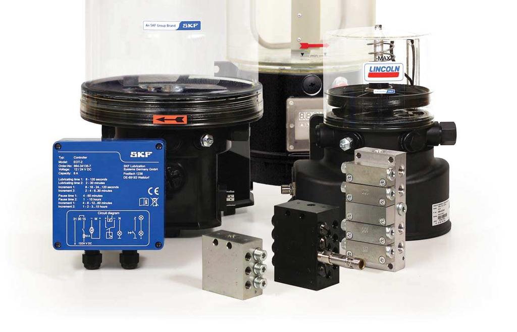
6 Two leading brands One global leader SKF and Lincoln have joined forces to provide you with the world s most complete portfolio of innovative lubrication solutions from manual lubricators and tools, to the most advanced centralized and automatic lubrication systems available. In addition to traditional lubrication products and systems, we offer customized solutions for many industries such as pulp and paper, steel, mining, agriculture, marine, rail, wind, construction, machine tool and automotive. SKF engineering and technical specialists partner with OEMs and end-users to develop system solutions based on customer requirements. We also offer a variety of control and monitoring equipment for ease of use and to help ensure proper lubrication. Both SKF and Lincoln systems are available through our global network of lubrication experts, offering you world-class installation and ongoing support on a local level today and into the future. With the power of this network, and more than 200 years of combined lubrication management experience, we can help you improve machine reliability, reduce maintenance, increase productivity, enhance safety and optimize manpower resources. Oil and fluid grease 6
.")
7 Classification of lubricants Oil and fluid grease The viscosity is an expression of a fluid s internal friction. Oils are classified in ISO VG viscosity classes from 2 to NLGI grade 000, 00 and 0 greases are called fluid greases. s are consistent lubricants (NLGI grade 1 6). They are soft to hard, triple-component mixtures of a base oil as the lubricating fluid, a thickening agent and additives. Different types of oils are available, including mineral oils, organic oils and synthetic oils. A compatibility check is recommended prior to using any oil with SKF lubrication systems. In most instances, greases of NLGI grade 1 up to 3 are suitable for use in a lubrication system. A compatibility check should be made prior to using any grease with SKF lubrication systems. Oil and fluid grease Lubricants suitable for lubrication systems fluid semi-fluid non-fluid Oil Fluid grease ISO VG N LGI grades

8 Progressive lubrication systems for oil, fluid grease and grease Oil and fluid grease System description SKF progressive systems, SKF ProFlex and Lincoln Quicklub, can be used on small- to medium sized machines with dispersed lubrication points that require varying lubrication quantities. Progressive systems consist of a pump connected to at least one primary metering device. If needed, second level metering devices can be connected to the outlets of the primary metering device to increase the number of lubricated points, depending on operating pressure of the pump. The outlets of the primary and second level metering devices are connected via branch lines to the lubrication points of the machine. A third level of metering devices is not recommended. The pump supplies lubricant to the metering devices with pressure up to 550 bar (8 000 psi), depending on the pump model. The metering devices split the lubricant into even or predefined amounts of lubricant, depending on metering device, that are positively displaced to the lubrication points or to the inlet of a connected secondary metering device. The lubricant amount provided by each outlet of the metering device depends on the type of metering device being used. SKF offers progressive systems that can dispense a precise, metered amount of lubricant to up to 150 lubrication points over distances of approximately 15 m (16 yd), depending on case values. For oil applications, even in connection with flow limiters we can cover distances over 100 m (110 yd), see also our portfolio brochure Oil Circulation Systems. SKF progressive systems provide continuous lubrication as long as the pump is in operation. Once the pump stops, the pistons of the progressive metering device will stop in their current positions. When the pump starts supplying lubricant again, the pistons will carry on where they left. Therefore, the progressive circuit of one outlet of the pump will stop when only one lubrication point is blocked. The blockage serves as a means of control and forces personnel to service the system. Only one outlet of a primary or a secondary metering device of one pump outlet can be monitored visually or electrically, depending on the chosen metering device. For planning a lubrication system, conditions the system will be used in need to be determined first. The number of lube points, back pressures at the lube points, operating temperature range, lubricant, the feed pump s drive energy, control and monitoring etc. need to be defined correctly. Attention to information on bearing or lube point information need to be paid too. The sum of all the quantities metered out by the system s metering devices needs to be completed by safety margin and expansion and compressibility loss. SKF application engineers as well as SKF sales partners and distributors are experts in systems laying out lubrication according to all these specifications. A lubrication system layed out by SKF and partners ensures the supply of the correct amount of lubricant at the best time to lubricate. This reduces wear and it avoids pollution caused by over-lubrication. 8
; on-road trucks (snow removal, waste press); buses;")
.")
, reciprocating compressors in the Oil & Gas industry, among many others.")
9 Systems and applications Oil and fluid grease Oil and fluid grease Applications The systems are suitable for a variety of applications including: construction machines (concrete pumps, mortar pumps, loaders, excavators, trenchers); on-road trucks (snow removal, waste press); buses; agricultural machines (harvesters, balers, manure spreaders, sugar cane loaders); wood reclaimers; and material handling (reach stackers, crane carts). In addition, progressive lubrication systems are suitable for use in asphalt mixing plants, wind turbine generators and food and beverage facilities (fillers, washing machines), reciprocating compressors in the Oil & Gas industry, among many others. SKF progressive systems are reliable and operate effectively in harsh conditions (inclusive ATEX) with potentially high lubrication-point back pressure, dirty, wet or humid environments and low temperatures. 9


10 Progressive lubrication systems Pumps and pump units P 203 KFG KFA QLS 301 QLS 401 QLS 421 P 502 P 223 / P 233 P 243 P 603M ZPU 01/02 EDL1 PPU-5 / PP / PP / PPG PFP-23-2 / PFP
11 Overview of grease pumps and pump units Electrically operated pumps and pump units 1) Product Metering quantity per pump element Reservoir Operation pressure max. Page cm³/min in³/min l gal bar psi P 203 0,7 4, KFG 0,8 5, KFA 1,0 2, QLS 301 SSV 1, QLS 401 SSV 1, QLS 401 SSVD 1, QLS 421 1, P 502 1,0 2, P 223 / P 233 0,7 4, P 243 0,7 4, P 603M 4,0 12, ZPU 01 / 02 13,3 53, ) These pumps are recommended by SKF for the use in grease progressive lubrication systems but can be used in many cases also with oil progressive lubrication systems. For further details please see the technical data information shown on the specific product pages. Electrically operated pressure booster pumps 1) Product Metering quantity per pump element Reservoir Operation pressure max. Page cm³/min in³/min l gal bar psi EDL1 0,5 1, ) These pumps are recommended by SKF for the use in grease progressive lubrication systems but can be used in many cases also with oil progressive lubrication systems. For further details please see the technical data information shown on the specific product pages. Air-operated pumps and pump units 1) Product Metering quantity Reservoir Operation pressure Page cm³/... in³/... bar psi PPU-5 0,10 0,50 /stroke /stroke 2,5; 5,0 l 0.66; 1.32 gal PPU-35 0,70 3,50 /stroke /stroke 2,5; 5,0 l 0.66; 1.32 gal ,164 0,98 /stroke /stroke ,41-0,164 /stroke /stroke ,01 0,05 /stroke 0.01 to 0.05 /stroke ,10 16,39 /stroke 0.25 to 1.0 /stroke 44 PP 2,6 /stroke 0.16 /stroke 0,4; 1,5 l 0.1; 0.4 gal PPG 0,2 /stroke /port/stroke 46 PFP ,25 /stroke/port /stroke/port 1,5 l 0.4 gal PFP ,50 /stroke/port /stroke/port 1,5 l 0.4 gal EPB 6,10 /cycle 0.37 /cycle 18; 50; 180 kg 40; 110; 400 lbs ) These pumps are recommended by SKF for the use in grease progressive lubrication systems but can be used in many cases also with oil progressive lubrication systems. For further details please see the technical data information shown on the specific product pages. 11

12 Progressive lubrication systems EPB PHU-35 PFH-23-2 / -22 HJ 2 HP / HPG HP-500 W PF-23-2 PF-VPBM /
13 Overview of grease pumps and pump units Hydraulically operated pumps and pump units 1) Product Metering quantity Reservoir Operation pressure max. Page cm³/stroke/.. in³/stroke/.. l gal bar psi ,164 0, ,41 1, PHU-5 0,1 0, ,5; 5,0 0.66; PHU-35 0,7 3, ,5; 5,0 0.66; PFH ,25 /port /port 1, PFH ,50 /port /port 1, ) These pumps are recommended by SKF for the use in grease progressive lubrication systems but can be used in many cases also with oil progressive lubrication systems. For further details please see the technical data information shown on the specific product pages. Manually operated pumps and pumps units 1) Product Metering quantity Reservoir Operation pressure max. Page cm 3 /stroke in 3 /stroke bar psi HJ l 0.79 gal HP / HPG 0,2; 1,6 /SSV outlet 0.012; /SSV outlet 0,4 1,5 l gal HP-500W 1, ,4 0,5 l gal HP-500-SSV 0,2 /SSV outlet /SSV outlet 0,4 0,5 l gal PF , ,5 l 0.4 gal PF , ,5 l 0.4 gal PF-VPBM 2, cm³ in³ ,2; 2,0 /VPBM outlet 0.012; 0.12 /VPBM outlet 450 cm³ in³ ) These pumps are recommended by SKF for the use in grease progressive lubrication systems but can be used in many cases also with oil progressive lubrication systems. For further details please see the technical data information shown on the specific product pages. 13

14 Pump unit P 203 The P 203 lubrication pump is versatile, compact and economical and can supply up to 150 lubrication points, depending on the line length. It consists of a housing with integrated motor, reservoir with stirring paddle, pump element with pressure-relief valve, filling nipple and electrical connection parts. This powerful pump can drive up to three pump elements and can be equipped with a low-level control (with or without control board). Features and benefits Optional control printed circuit boards with different operating settings Range of reservoir types offered For DC or AC applications Variety of pumping elements for different output available Applications Mobile applications Wheel loaders Excavators Small- and medium-sized machinery General industries Combines, balers, forage harvesters Technical data Function principle electrical piston pump Operating temperature V DC version: 40 to +70 C; 40 to +158 F V AC version: 25 to +70 C; 13 to +158 F Operating pressure bar; psi Lubricant grease: up to NLGI 2 oil: with min. 40 mm²/s Outlets up to 3 Metering quantity per pump element: K 5; B2: 2,0 cm³/min; in³/min K 6: 2,8 cm³/min; in³/min K7,C7: 4 cm³/min; in³/min KR adjustable: 0,7-3,0 cm³/min; in³/min Reservoir ; 4; 8 and 15 l 0.53, 1.05, 2.11 and 3.96 gal Connection main line G 1 / 4 Operating voltage /24 V DC, V AC; 50/60 Hz Dimensions min mm min in max mm max in Mounting position with follower plate: any without follower plate: upright! NOTE For further technical information, technical drawings, accessories, spare parts or product function descriptions, see the following publication available online at SKF.com/lubrication: EN 14
15 Pump unit P 203 Order number configurator P 203 Product series P 203 = with 1-3 outlets and V DC motor Reservoir = [x] select size in liter 1) [x] XN = closed, 2, 4 or 8 l; 0.52; 1.06, 2.11 gal 2 XNFL = flat, 2 l; 0.52 gal [x] XNBO = with lid, 2, 4, 8 or 15 l; 0.52; 1.06, 2.11 or 3.96 gal [x] XL = low-level control, 2, 4 or 8 l; 0.52; 1.06, 2.11 gal [x] XBF = high-/low-level control, follower plate, 4; 8 or 15 l; 1.06, 2.11 or 3.96 gal [x] XLBO = low-level control, with lid; 2, 4, 8 or 15 l; 0.52; 1.06, 2.11 or 3.96 gal [x] YLBO = for oil, low-level control, with lid; 4 or 8 l; 1.06or 2.11 gal [x] YNBO = for oil, with lid, 4, 8 or 15 l; 1.06, 2.11 or 3.96 gal Pump elements [x] select 1-3 = number of elements used [x] K5 = piston ø 5 mm [x] K6 = piston ø 6 mm [x] K7 = piston ø 7 mm Operating voltage 12 = 12 V DC, with square plug, bayonet plug or M 12 plug 24 = 24 V DC, with square plug, bayonet plug or M 12 plug AC = V AC, ±10%, 50/60 Hz ±5%, with square plug 3) [x] KR = adjustable, piston ø 7 mm [x] B7 = piston ø 7 mm, with bypass-check valve [x] C7 = piston ø 5 mm 2) Number of possible connections 1A = 1 connection, supply voltage V DC, V AC 3) 1A: power supply V AC, square plug only, left bottom 1A: power supply V DC, left up 2A = 2 connections 4) 1 A: power supply V AC, square plug only, bottom left, V DC 2 A: illuminated pushbutton, low-level control or piston detector, see below piston detector 3A = 3 connections 3) 1 A: power supply V AC, square plug only, bottom left, V AC 3) 2 A: illuminated pushbutton, low-level control bayonett plug, left top 3 A: piston detector, bayonet plug, right top Type of connection 1. = square plug, power supply. DIN = M 12 plug 5. = bayonet plug, 4/3 pole design, DIN Connection outside of pump 01 = without socket, without cable 10 = connection socket, with cable (10 m; 33 ft) 11 = connection socket, ADR cable (10 m; 33 ft) 13 = bayonet socket with cable (10 m; 33 ft), 7/5-core, M08-M23 6. = bayonet plug 7/5 pole design, M08-M23 7. = bayonet plug 7/6 pole design, V10-V13, V20-V23 8. = PG cable gland 14 = bayonet socket with cable (10 m; 33 ft), 4/3-core 15 = bayonet socket with cable (10 m; 33 ft), 7/5-core 16 = bayonet socket with cable (10 m; 33 ft), 7/6-core Control P.C.B. = without control printed circuit board V10 V13 = with variably adjustable pause and lubricating time, (V20-V23 for US market) V10 V13-ADR = with variably adjustable pause and lubricating time 5) M08 - M23 = with microprocessor control (different setting variants, monitored systems) H = for trailers and semi-trailers H-ADR = for trailers and semi-trailers 5) 1) the high-/low-level control can not be combined with the integrated control P.C.B. 2) designation for pump elements for supplying of paste for chisel (c=chisel) 3) equipment described in seperate documentation 4) no connection provided for low-level control for oil & 2A: with illuminated pushbutton only 5) for transport of hazard materials 15

16 Pump unit KFG The electrically operated KFG pump includes a drive shaft with an eccentric that drives up to three pump elements. It is comprised of four main components: housing with pump elements, reservoir with fill-level monitoring, internal control units and attachments. The pump is available in eight sizes and two variants for stationary use or with grease follower plate technology for utilization in any position. A variety of attachments permit reservoir filling, protect the pump (pressure-limitation valve) or enable the uncomplicated connection of the pump to a centralized lubrication system. Features and benefits Durable and reliable components designed for extreme conditions (with positively driven pump elements) Versatile; can be used with single-line and progressive systems Fill-level and lubrication system monitoring Pin code protection of control unit available Applications Vehicles, Off-road vehicles Industrial Renewable energy! NOTE For further technical information, technical drawings, accessories, spare parts or product function descriptions, see the following publication available online at SKF.com/lubrication: EN; ; ; Technical data Function principle electrically operated piston pump Operating temperature to +70 C; -22 to +158 F depending on type of pump element Operating pressure to 300 bar; to psi depending on type and size of pump element Lubricant grease NLGI 000 to 2, compatible with plastics, NBR elastomers, copper and copper alloys Outlets up to 3 Metering quantity per pump element: 0,8; 1,3; 1,8; 2,5; 5,0 cm³/min 0.049, 0.079, 0.11, 0.15, 0.31 in³/min Reservoir ; 4; 6; 8; 10; 12; 15 and 20 kg 4.4, 8.8, 13.2, 17.6, 22, 26.5, 33 and 44 lbs Material pump housing aluminum-silicon cast alloy reservoir ; 6 kg; 4.4, 13.2 lbs: Polyamide PA 6I 4; 8; 10; 12; 15; 20 kg; 8.8, 17.6, 22, 26.5, 33, 44 lbs: PMMA Connection outlet pump element: M 14 1,5 female thread Power supply V DC, 24 V DC, 230 or or 90 to 264 V AC; (± 10%) Dimensions min mm min in max ,170 mm max in Mounting position with follower plate any, installation possible also in rotating machines, e.g. wind turbines without follower plate upright 16
17 Pump unit KFG Order number configurator KFG + Product series Integrated control unit X = no control unit S = IG502-2-I L = LC502 C = CAN bus Reservoir 1 = 2 kg, 4.4 lbs 1) 2 = 4 kg, 8.8 lbs 2) 3 = 6 kg, 13.2 lbs 4 = 8 kg, 17.6 lbs 2) Range of application R = rotary application M = industry application F = vehicle application Filling X = without lubricant, not available for rotary application version A = grease NLGI 2 for vehicles, not for capacitive fill level monitor F = customized grease Fill level monitor X = without fill level monitor 1 = mechanical level monitor 1) 2 = mechanical level monitor with signal smoothing (only available for KFGX) 1) 3 = capacitive level monitor, only available for industry version with 2 and 6 kg reservoir and NLGI 2 4 = cylinder switch level monitor 2) Pump element or filler socket Spring return piston pump 3) X = no pump element D = 0,8 cm³/min; 0.05 in³/min C = 1,3 cm³/min; 0.08 in³/min B = 1,8 cm³/min; 0.10 in³/min A = 2,5 cm³/min; 0.15 in³/min E = 5,0 cm³/min; 0.30 in³/min W = socket for filling cylinder 1) Positively driven piston pump 4) Y = no pump element J = 1,3 cm³/min; 0.08 in³/min H = 1,8 cm³/min; 0.10 in³/min G = 2,5 cm³/min; 0.15 in³/min L = 5,0 cm³/min; 0.30 in³/min V = socket for filling cylinder 1) Fitting for main line connection and valves X = without attachments (with M 14 1,5 mm female thread) B = without attachments (with G 1 / 4 female thread) C = solderless pipe union for ø 6 mm tubes D = solderless pipe union for ø 8 mm tubes E = solderless pipe union for ø 10 mm tubes F - P = with pressure relief valve F = 300 bar; psi, with SKF Quick Connector for ø 6 mm tubes 5) G = 300 bar; psi, with solderless pipe union for ø G 1 / 4 tubes 5) H = 300 bar; psi, with solderless pipe union ø 6 mm tubes 5) J = 300 bar; psi, with solderless pipe union ø 8 mm tubes 5) K = 300 bar; psi, with solderless pipe union ø 10 mm tubes 5) L = 300 bar; psi, with SKF Quick Connector for ø 8 mm tubes 5) M = 200 bar; psi, with solderless pipe union for ø 8 mm tubes N = 200 bar; psi, with solderless pipe union for ø 10 mm tubes O = 200 bar; psi, with solderless pipe union for ø 12 mm tubes P = 200 bar; psi, with SKF Quick Connector for ø 8 mm tubes Pump cycle / interval time 99 = none EB/EO = 4 min. runtime / 1 h interval time (IG502-2-I/ LC502) 6) Operating voltage 912 = 12 V DC, only available for vehicle application version 486 = V AC, not available for vehicle application version 924 = 24 V DC 1) not available for rotary application version 2) only available for rotary application version 3) operating pressure 300 bar for spring return pump (200 bar for pump element E) 4) operating pressure 350 bar for positively driven pump (250 bar for pump element L) 5) F,G,H,J,K,L: not for pump element E and L 6) factory setting, other settings available 17

18 Pump unit KFA KFA(S) series pumps include a maximum of two outlet ports to connect two independent lubrication circuits. A separate pump element is required for each outlet. Three pump elements with different delivery rates are available so that the volume of grease can be adjusted to individual circuit needs. This ensures that every lubrication point is supplied with an adequate amount of grease in each lubrication cycle. An integrated IG control and monitoring unit operates in a time- or load- (pulse) dependent mode, with or without monitoring. Features and benefits Integrated control system provides: Non-volatile memory with PIN-code protection Storage of residual interval, lubricating cycle and faults signals Saved data in event of a power failure Connection for external pushbutton and inductive cycle switch Interval and contact times can be set independently Fits in tight/small places Applications Commercial vehicles 230 V AC models for industrial applications Machine tools Printing industry Technical data Function principle electrical piston pump Operating temperature to +75 C -13 to +167 F Operating pressure bar; psi Lubricant grease up to NLGI 2 Outlets to 2 Metering quantity ,0; 1,5; 2,0 cm³/min 0.061; 0.092; in³/min Reservoir l; 0.26 gal Connection main line M Operating voltage and 24 V DC; 115 and 230 V AC; (± 10%) Protection class IP 6K9K Dimensions ,5 mm in Mounting position upright! NOTE For further technical information, technical drawings, accessories, spare parts or product function descriptions, see the following publication available online at SKF.com/lubrication:
19 Pump unit KFA KFA pump unit Order number Designation Monitoring Control unit applications level monitoring cycle switch extern integrated V DC V DC V AC V AC KFA1 912 vehicles KFA1 924 vehicles KFA1-W 912 vehicles KFA1-W 924 vehicles KFAS1 912 vehicles KFAS1 924 vehicles KFAS1-W 912 vehicles KFAS1-W 924 vehicles KFA1-M 924 industry KFA1-M-W 924 industry KFAS1-M 924 industry KFAS1-M-Z 924 industry KFAS1-M-W 924 industry KFAS1-M-W-Z 924 industry KFA industry KFA10-W 263 industry KFAS industry KFAS10-W 485 industry 1) only pump; pump elements need to be ordered separatly Accessories Cable kits, pump elements Cable kits KFA1.U1 Order number Designation cable kit for pump KFA1, square type cable kit bayonet for pump KFAS1 and KFAS1-W, 7-pins, (12 m, 39 ft) cable kit bayonet for pump KFAS1 and KFAS1-W, 7-pins, (16 m, 52 ft) KFA pump elements Order number Designation Metering quantity cm³/min in³/min KFA1.U1 pump element 2, KFA1.U2 pump element 1, KFA1.U3 pump element 1,


.")
 Protection class.")
20 Pump unit QLS 301 SSV The Quicklub QLS 301 is a compact lubrication system designed to supply grease. The system package includes all necessary monitoring and control functions, as well as low-level control and a pressure-relief valve. Outlet connections and standard-pressure plastic tubing must be ordered separately. Up to 18 lubrication points can be supplied and monitored directly from the pump, and its reservoir features a follower plate, enabling rotating applications. The unit s integrated, all-in-one system concept reduces installation time and costs. Features and benefits Back- or bottom-mounted progressive metering devices Internal lubricant return possible Integrated pressure-relief valve External programming via keypad System monitoring with display of faults Follower plate Applications Machine tools Material handling Automotive industry Food processing Printing industry Renewable energies Agriculture machinery Construction Technical data Function principle electrically operated piston pump with follower plate Operating temperature to +70 C; 13 to +158 F Operating pressure bar; psi Lubricant grease: NLGI 2 fluid grease: NLGI 00, 000 Outlets up to 18 Metering quantity 1) ,0 cm³/min; 0.06 in³/min Reservoir l; 0.26 gal Connection main line via SSV: see information for SSV via connection block: G 1 /8 Operating voltage /24 V DC; 120 and 230 V AC (± 10%) Protection class IP 6K9K, NEMA 4 Dimensions min mm min in max mm max in Mounting position any 1) before metering devices! NOTE For further technical information, technical drawings, accessories, spare parts or product function descriptions, see the following publication available online at SKF.com/lubrication: EN 20
21 Pump unit QLS 301 SSV Order number configurator P301 1 Product series Metering devices SVV... 0 = external SSV 6-KNQLS, SSV 8-KNQLS 1 = external SSV 12-KNQLS, SSV 18-KNQLS 3 = SSV 6, rear-mounted 4 = SSV 8, rear-mounted 6 = SSV 12, rear- or bottom-mounted 9 = SSV 18, rear- or bottom-mounted Assignment of metering device outlets 0 = no metering device 1 = vertical metering device outlets, V, rear mounted 2 = horizontal metering device outlets, H, bottom-mounted 1) Supply voltage 2 = 12 V DC, available with or without control P.C.B. 4 = 24 V DC, available with or without control P.C.B. 6 = 120 V AC, available with control P.C.B. only 8 = 230 V AC, available with control P.C.B. only Reservoir 1 = 1XL, 1 l; 0.26 gal, with low-level indication Connections 0 = 1 connection left side: power supply (V DC / V AC) 1A, square plug. For industrial applications 2 = 1 connection left side: power supply (V DC) 1A, low-level or fault indication, bayonet plug. For vehicles only 1 = 2 connections: 1 left side for power supply (V DC / V AC) 2A; 1 right side for external low-level or fault indication, square plug. For industrial applications Connection socket design 1 = square plug design A. For industrial applications 2) 5 = bayonet plug 4-pole design. For vehicles 3) Electrical connector types 1 = with connection socket, without cable 2) 5 = with connection socket and cable (10 m; 33 ft) 2) 6 = with connection socket and ADR cable (10 m; 33 ft)) 2) 7 = with connection socket, bayonet and cable (10 m; 33 ft) 3) 8 = with connection socket, bayonet and ADR cable (10 m; 33 ft) 3) Control printed circuit board (P.C.B.) 0 = without 4 = control P.C.B. S4; NC and NO contacts programmable 1-5 cycles; only for V DC application 4 = control P.C.B. S4; NC and NO contacts programmable; 1-3 cycles, SSV 6/ SSV 8; 1 cycle, SSV 12/ SSV 18; only for V AC application 1) Not for use in areas with impact loads or vehicles 2) Connection types 1, 5, 6 can be combined with square plug version (1) only 3) Connection types 7, 8 can be combined with bayonet plug version (5) only 21


.......... 1,0 cm³/min 0.06 in³/min Reservoir.................. 1 and 2 l 0.")
22 Pump unit QLS 401 SSV The Quicklub QLS 401 SSV is a complete lubrication system that includes all necessary monitoring and control functions, as well as a pressure-relief valve and an enhanced reservoir-stirring paddle that prevents grease separation. Outlet connections and standard-pressure plastic tubing must be ordered separately. Up to 18 lubrication points can be supplied via an SSV metering device with fixed output amount and can be monitored directly from the pump. The unit s integrated, all-in-one system concept reduces installation time and costs. Features and benefits Back- or bottom-mounted metering devices Internal lubricant return possible Integrated pressure-relief valve External programming via keypad System monitoring with display of faults Applications Industrial and mobile applications Food processing Agriculture machinery Machine tools Technical data Function principle electrically operated piston pump with stirring paddle Operating temperature to +70 C 13 to +158 F Operating pressure bar psi Lubricant grease: up to NLGI 2 fluid grease: NLGI 00, 000 Outlets up to 18 Metering quantity 1) ,0 cm³/min 0.06 in³/min Reservoir and 2 l 0.26 and 0.53 gal Connection main line via SSV: see information for SSV, p. 84 via connection block: G 1 /8 Operating voltage /24 V DC; 120 and 230 V AC (± 10%) Protection class IP 6K9K, NEMA 4 Dimensions min mm min in max mm max in Mounting position upright 1) before metering devices! NOTE For further technical information, technical drawings, accessories, spare parts or product function descriptions, see the following publication available online at SKF.com/lubrication: EN 22
23 Pump unit QLS 401 SSV Order number configurator P 401 Product series Metering devices 0 = external metering device SSV 6-KNQLS, SSV 8-KNQLS 1 = external metering device SSV 12-KNQLS, SSV 18-KNQLS 3 = SSV 6, rear-mounted 4 = SSV 8, rear-mounted 6 = SSV 12, rear- or bottom-mounted 9 = SSV 18, rear- or bottom-mounted Assignment of metering device outlets 0 = no metering device 1 = vertical metering device outlets V, back mounted 2 = horizontal metering device outlets H, bottom-mounted 1) Supply voltage 2 = 12 V DC, available with or without control P.C.B. 4 = 24 V DC, available with or without control P.C.B. 6 = 120 V AC, available with control P.C.B. only 8 = 230 V AC, available with control P.C.B. only Reservoir 0 = 1XN, 1 l; 0.26 gal, without low-level indication 1 = 1XL, 1 l; 0.26 gal, with low-level indication 2 = 2XN, 2 l; 0.53 gal, without low-level indication 3 = 2XL 2 l; 0.53 gal, with low-level indication Number of possible connections 0 = 1 connection left side, power supply (V DC/ V AC) 1A, square plug. For industrial applications 2 = 1 connection left side, power supply (V DC) 1A, low-level or fault indication, bayonet plug. For vehicles only 1 = 2 connections: 1 left side for power supply (V DC/ V AC) 2A 1 right side for external low-level or fault indication, square plug. For industrial applications Connection socket design 1 = square plug design A. For industrial applications 2) 5 = bayonet plug 4-pole design.for vehicles 3) Type of electrical connectors 1 = with connection socket, without cable 1) 5 = with connection socket and cable (10 m; 33 ft) 1) 6 = with connection socket and ADR cable (10 m; 33 ft) 1) 7 = with connection socket, bayonet and cable (10 m; 33 ft) 2) 8 = with connection socket, bayonet and ADR cable (10 m; 33 ft) 2) Control printed circuit board (P.C.B.) 0 = without 4 = control P.C.B. S4 for 12/ 24 V DC; NC and NO contacts programmable 1-5 cycles 4 = control P.C.B. S4 for 120/ 230 V AC; NC and NO contacts programmable; 1-3 cycles (SSV 6/ SSV 8), 1 cycle (SSV 12/ SSV 18) 5 = control P.C.B. S4 for 12/ 24 V DC; NO contact signal 4) 5 = control P.C.B. S5 for 120/ 230 V AC; NO contact signal; 1-3 cycles, (SSV 6/ SSV 8), 1 cycle (SSV 12/ SSV 18) 4) 6 = control P.C.B. S6 for 12/ 24 V DC; NC contact signal 4) 6 = control P.C.B. S6 for 120/ 230 V AC; NC contact signal; 1-3 cycles (SSV 6/ SSV 8) 1 cycle (SSV 12/ SSV 18) 4) 1) Not for use in areas with impact loads or vehicles 2) Connection types 1, 5, 6 can be combined with square plug version (1) only 3) Connection types 7, 8 can be combined with bayonet plug version (5) only 4) Control P.C.B. can be combined with XN reservoir versions only 23

24 Pump unit QLS 401 SSVD The Quicklub QLS 401 SSVDV is a complete lubrication system that includes all necessary monitoring and control functions, as well as a pressure-relief valve and an enhanced reservoir-stirring paddle that prevents grease separation. Outlet connections and standard-pressure plastic tubing must be ordered separately. Up to 16 lubrication points can be supplied via an SSVDV metering device with adjustable output amount (using metering screws) and can be monitored directly from the pump. The unit s integrated, all-in-one system concept reduces installation time and costs. Features and benefits Back- or bottom-mounted metering devices Internal lubricant return possible Integrated pressure-relief valve External programming via keypad System monitoring with display of faults Applications Industrial and mobile applications Food processing Agriculture machinery Machine tools Technical data Function principle electrically operated piston pump with stirring paddle Operating temperature to +70 C 13 to +158 F Operating pressure bar psi Lubricant grease: up to NLGI 2 fluid grease: NLGI 00, 000 Outlets max. 16 Metering quantity 1) ,0 cm³/min 0.06 in³/min Reservoir and 2 l 0.26 and 0.53 gal Main line connection via SSV: see information for SSVD, see p. 80 via connection block: G 1 /8 Operating voltage /24 V DC; (± 10%) Protection class IP 6K9K, NEMA 4 Dimensions min mm min in max mm max in Mounting position upright 1) before metering devices! NOTE For further technical information, technical drawings, accessories, spare parts or product function descriptions, see the following publications available online at SKF.com/lubrication: EN and EN 24
25 Pump unit QLS 401 SSVD Type identification code P 401 Product series Metering devices SSVDV 6 = rear-mounted, vertical outlets, V SSVDV 12 = rear-mounted, vertical outlets, V SSVDV 16 = rear-mounted, vertical outlets, V Metering screws per pair of outlets 1) A = 0,08 cm 3 ; in 3 B = 0,14 cm 3 ; in 3 C = 0,20 cm 3 ; in 3 D = 0,30 cm 3 ; in 3 E = 0,40 cm 3 ; in 3 F = 0,60 cm 3 ; in 3 G = 0,80 cm 3 ; in 3 H = 1,00 cm 3 ; 0.061in 3 I = 1,40 cm 3 ; in 3 J = 1,80 cm 3 ; in 3 Marks the mounted metering screws per pair of outlets, starting with the highest pair of outlets. The number of metering screws in the identification code corresponds to half of the metering device s outlets. Supply voltage 12 DC = 12 V DC, available with or without control P.C.B. 24 DC = 24 V DC, available with or without control P.C.B. Reservoir 1XN = 1 l; 0.26 gal, reservoir without low-level indication 1XL = 1 l; 0.26 gal, reservoir with low-level indication 2XN = 2 l; 0.52 gal, reservoir without low-level indication 2XL = 2 l; 0.52 gal, reservoir with low-level indication Number of possible connections 1A = 1 connection left side, power supply (V DC/ V AC), square plug. For industrial applications 1A = 1 connection left side, power supply (V DC), low-level or fault indication, bayonet plug. For vehicles only 2A = 2 connections, 1 left side for power supply (V DC/V AC), 1 right side for external low-level or fault indication square plug. For industrial applications Connection socket design 1. = square plug design A. For industry 1) 5. = bayonet plug 4-pole design. For vehicles 2) Type of electrical connectors 1 = with connection socket, without cable 1) 5 = with connection socket and cable (10 m; 33 ft) 1) 6 = with connection socket and ADR cable (10 m; 33 ft) 1) 7 = with connection socket, bayonet and cable (10 m; 33 ft) 2) 8 = with connection socket, bayonet and ADR cable (10 m; 33 ft) 2) Control printed circuit board (P.C.B.) = without S4 = control P.C.B. S4 for 12/ 24 V DC; NC and NO contacts programmable 1-5 cycles 1) Connection types 1, 5, 6 can be combined with square plug version (1) only 2) Connection types 7, 8 can be combined with bayonet plug version (5) only 25


26 Pump unit QLS 421 Designed for lubricating truck trailers and semi-trailers, the Quicklub QLS 421 is a complete lubrication system with an integrated metering device and controller, as well as a pressure-relief valve. The pump features a back-mounted SSV metering device and supplies grease only. Outlet connections and standard-pressure plastic tubing must be ordered separately. Up to 18 lubrication points can be supplied directly from the pump. Features and benefits Compact progressive system Designed to supply grease Uses brake light as power supply via capacitor Lubricates at each braking until reaching set lubrication time Applications Vehicles Trailers, Semi-trailers Agriculture machinery Construction Technical data Function principle electrically operated piston pump for trailers and semi-trailers Operating temperature to +70 C 13 to +158 F Operating pressure bar psi Lubricant grease: up to NLGI 2 fluid grease: NLGI 00, 000 Outlets up to 18 Metering quantity ,0 cm³/min 0.06 in³/min Reservoir ; 2 l 0.26; 0.53 gal Connection main line via SSV: see information for SSV, p. 84 via connection block: G 1 /8 Operating voltage / 24 V DC Protection class IP 6K 9K, NEMA 4 Dimensions min mm min in max mm max in Mounting position upright 26
27 Pump unit QLS 421 Order number configurator P Product series Metering devices 3 = SSV 6 6 = SSV 12 9 = SSV 18 Metering device position 1 = rear-mounted Operating voltage 2 = 12 V DC 4 = 24 V DC Reservoir / low-level control 0 = 1 l; 0.26 gal; without low-level control 2 = 2 l; 0.53 gal; without low-level control Number of possible connections 2 = 1A5-1 connection, power supply, bayonet plug, left Connection socket design 5 = bayonet plug according to DIN Type of electrical connectors 3 = with socket and cable (10 m; 33 ft) 4 = with socket and cable ADR (10 m; 33 ft) Control printed circuit board (P.C.B.) 1 = with variable pause and lubrication time 27


28 Pump unit P 502 The P 502 is a simple, economical, electrically operated lubrication pump unit. It can provide directly a maximum of two individual lubrication points with lubricant or be connected to progressive metering devices. An integrated control board is available to set pause and lubrication time. Developed for fluid grease and grease, the P502 features an optimized housing shape and reservoir suitable for food processing applications. Features and benefits Economical operation Fits in tight/small places Flexible design for 12 and 24 V DC voltage supply Optional pressure-release valve Optimised housing design for splash zones in food processing Applications Industry Small constructions Food and beverage industry Commercial vehicles On/off road Agriculture machinery Technical data Function principle electrically operated piston pump Operating temperature to +70 C 13 to +158 F Operating pressure bar; psi Lubricant grease up to NLGI 2 Outlets Metering quantity per pump element: 1.0; 1.2; 1.8; 2.4 cm³/min 0.06; 0.07; 0.11; 0.15 in³/min Reservoir l; 0.26 gal Connection main line G 1 /4 Operating voltage /24 V DC Protection class IP6K9K, IP65, IP67 depending on type of electrical connection Dimensions mm in Mounting position with follower plate any without follower plate upright! NOTE For further technical information, technical drawings, accessories, spare parts or product function descriptions, see the following publication available online at SKF.com/lubrication: EN 28
29 Pump unit P 502 Order number configurator P 502 Product series Reservoir plastic 1XN = for grease 1 l; 0.26 gal 1YN = for oil 1 l; 0.26 gal 1XLF = for grease, with follower plate and low-level signal, 1 l; 0.26 gal Pump elements, [x] select number o of pump elements (1 or 2) [x] K5 = piston ø 5 mm [x] K6 = piston ø 6 mm [x] K7 = piston ø 7 mm [x] B7 = piston ø 7 mm 00 = without pump elements Supply voltage 12 = 12 V DC 24 = 24 V DC Electrical connection 1A = 1 connection left-side supply voltage 2A = 2 connections: - 1 connection left-side, supply voltage - 1 connection right-side, low-level signal, illuminated pushbutton Type of connection 1. = square plug 2. = M 12 plug 5. = bayonet plug 4-pole, DIN = bayonet plug 7/5-pole, DIN = bayonet plug 7/6-pole, DIN Connections from the pump to external devices 00 = connection plug with closure cap, square plug 01 = connection plug and socket, square plug 10 = connection plug and socket, square plug, cable (10 m; 33 ft) 14 = bayonet socket, 4-core, cable (10 m; 33 ft) 15 = bayonet socket, 7/5-core, cable (10 m; 33 ft) 16 = bayonet socket, 7/6-core, cable (10 m; 33 ft) Control printed circuit boards (p.c.b) 00 = without control printed circuit board V10-V13 = control printed circuit board, supply voltage terminals V20-V23 = control printed circuit board, supply voltage terminals
 with metering device monitoring and can drive up to three pump elements. The P 233 provides supplementary Datalogger function for data transfer to Quickdata 2.0 diagnostic software.")

30 Pump unit P 223 / P 233 Similar to the P 203 series, the P 223/233 pumps feature an integrated control printed circuit board (P.C.B.) with metering device monitoring and can drive up to three pump elements. The P 233 provides supplementary Datalogger function for data transfer to Quickdata 2.0 diagnostic software. Versatile, compact and economical, the P 233 pump is enhanced with low-level control, printed circuit board MDF01 with attached Datalogger module and a keypad with display. Features and benefits Datalogger P 233 shows system settings and events including general data, pumping times, programming, operating times, malfunction and low-level indication Using Quickdata 2.0 diagnostic software, data can be read out via laptop and infrared interface Applications Mobile applications Track tamping machines Stationary systems Vehicles and construction machines Technical data Function principle electrically operated piston pump Operating temperature to +70 C 13 to +158 F Operating pressure bar psi Lubricant greases up to NLGI 2 oil: with min. 40 mm²/s Outlets up to 3 Metering quantity per pump element K5,B7: 2 cm³/min; 0.12 in³/min K6: 2,8 cm³/min; 0.17 in³/min K7,C7: 4 cm³/min; 0.24 in³/min KR adjustable: 0,7-3,0 cm³/min, in³/min Reservoir , 4, 8, and 15 l 0.53, 1.05, 2.11 and 3.96 gal Operating voltage /24 V DC; 100/260 V AC; 50/60 Hz Connection main line G 1 /4 Protection class IP 6K 9K Dimensions min mm min in max mm max in Mounting position with follower plate any without follower plate upright 30
31 Pump unit P 223 / P 233 Order number configurator Product series for grease with 1-3 outlets and V DC motor P 223 = pump with Datalogger P 233 = pump without Datalogger Reservoir [x] select size in liter 2,4, 8 or 15 1) [ ] XN = closed, 2 l; 0.52 gal 2 XNFL = flat, 2 l; 0.52 gal [ ] XNBO = with lid, 2, 4, 8 or 15 l; 0.52; 1.06, 2.11 or 3.96 gal [ ] XL = low-level control, 2, 4 or 8 l; 0.52; 1.06, 2.11 gal [ ] XLBO = low-level control, with lid; 2, 4, 8 or 15 l; 0.52; 1.06, 2.11 or 3.96 gal [ ] YNBO = for oil, with lid, 4, 8 or 15 l; 1.06, 2.11 or 3.96 gal [ ] YLBO = for oil, low-level control, with lid; 4 or 8 l; 1.06or 2.11 gal Pump elements 1-3 = number of elements used K5 = piston ø 5 mm K6 = piston ø 6 mm K7 = piston ø 7 mm, with bypass bore Operating voltage 12 = 12 V DC 24 = 24 V DC KR = adjustable, piston ø 7 mm B7 = piston ø 7 mm, with bypass-check valve C7 = piston ø 5 mm 2) AC = V AC, 50/60 Hz Number of possible connections 2A = 2 connections: on the left top power supply, illuminated pushbutton (operational test & additional lubrication) and fault indication 3) 4) on the right top piston detector, divider monitoring, bayonet plug 4/2 3A = 3 connections: on the left bottom power supply, square-type plug on the left top illuminated pushbutton and fault indication 3) 4) on the right top piston detector, divider monitoring, bayonet plug 4/2-pole Type of connection 5) 1. = square plug, power supply. DIN = bayonet plug, 4 pole design, DIN , for MF01/MDF01 3) 6. = bayonet plug 7/5 pole design, MF02/MDF02 4) Connection outside pump 15 = without socket, without cable 14 = bayonet socket with cable (10 m; 33 ft), 4-core; only with type of connection 2A5 / 3A5 15 = bayonet socket with cable (10 m; 33 ft), 7/5-core; only with type of connection 2A6 / 3A6 Control printed circuit boards 12/24 V DC MF01 = with microprocessor and membrane keypad, contact 15/30 bridged MF02 = with microprocessor and membrane keypad, contact 15/30 not bridged; only with type of connection 2A6 MDF01 = with microprocessor and membrane keypad and Datalogger, contact 15/30 bridged MDF02 = with microprocessor and membrane keypad and Datalogger, contact 15/30 bridged; only with type of connection 2A6 1) high-/low-level control can not be combined with the integrated control unit P.C.B. 2) designation for pump elements for supplying of paste for chisel (c=chisel) 3) for MF01/MDF01 4) for MF02/MDF02 5) other types of connection on request possible 31


32 Pump unit P 243 Similar to the P 203 pump series, the P 243 additionally provides Datalogger function for data transfer to Quickdata 2.0 diagnostic software. The main difference in the pumps is the type of printed circuit board, Datalogger functionality via a connected PC/Laptop. Features and benefits Offers Datalogger function using Quickdata 2.0 and higher diagnostic software Provides variety of control options and time and cycle settings Possibility to control and monitor up to three circuits P.C.B. with integrated temperature sensor Password protected Applications Mobile applications Stationary systems Track tamping machines Vehicles and construction machines Technical data Function principle electrical piston pump Operating temperature to +80 C 40 to +176 F Operating pressure bar; psi Lubricant grease: up to NLGI 2 oil: with min. 40 mm²/s Outlets up to 3 pump elements Metering quantity per pump element K5,B7: 2 cm³/min; 0.12 in³/min K6: 2,8 cm³/min; 0.17 in³/min K7,C7: 4 cm³/min; 0.24 in³/min KR adjustable: 0,7-3,0 cm³/min in³/min Reservoir , 4, 8, and 15 l 0.53, 1.05, 2.11, and 3.96 gal Connection main line G 1 /4 Operating voltage V DC V AC, 50/60 Hz Dimensions min mm min in max mm max in Mounting position with follower plate any without follower plate upright! NOTE For further technical information, technical drawings, accessories, spare parts or product function descriptions, see the following publication available online at SKF.com/lubrication: EN 32
33 Pump unit P 243 Order number configurator P 243 Product series Reservoir 2 = plastic, transparent, 2 l; 0.53 gal 4 = plastic, transparent, 4 l; 1.05 gal 8 = plastic transparent, 8 l; 2.11 gal 15 = plastic, transparent, 15 l; 3.96 gal Lubrication type X = grease Y = oil Fluid level indicator N = without low-level L = with low-level B = with high- and low-level Filling position BO = filling from top F = filling from bottom Pump elements, [X] = number of pump elements, 1-3 [X] K5 = piston ø 5 mm [X] K6 = piston ø 6 mm [X] K7 = piston ø 7 mm [X] B7 = piston ø 7 mm [X] C7 = piston ø 7 mm... = without pump elements Supply voltage 24 = 24 V DC, bayonet plug / M 12 AC = V AC, 50/60 Hz, square plug Electrical connections 2A = 2 connections, L (left) - supply voltage of pump, low-level signal, R (right)- piston detector 3A = 3 connections L (left) - supply voltage of pump, low-level signal, R (right) - piston detector 4A = 4 connections L (left) - supply voltage of pump + control P.C.B. low-level signal, illuminated pushbutton, R - piston detector, M 12 Type of connection 1. = square plug, V AC 2. = M 12 plug, V DC 7. = bayonet plug 7/7 pole, DYN 72585, to be used non-isolated only Connections to external devices 00 = connecting plug with closure cap, square plug 01 = connecting plug and socket, square plug, M 12 plug 10 = connecting plug and socket, M 12 plug, with cable (10 m; 33 ft) 16 = bayonet plug 7/7, 7-core, with cable (10 m; 33 ft) Control printed circuit boards MD 21 = potential-free (without jumper configuration) Adjustment if no indications are available regarding the control printed circuit board P.C.B. MD 20-8 = relay 1 (e) = plus relay 2 (v) = plus relay 3 (l) = plus MD 20-1 = relay 1 (e) = minus relay 2 (v) = minus relay 3 (l) = minus MD 20-2 = relay 1 (e) = minus relay 2 (v) = minus relay 3 (l) = plus MD 20-3 = relay 1 (e) = minus relay 2 (v) = plus relay 3 (l) = minus MD 20-4 = relay 1 (e) = minus relay 2 (v) = plus relay 3 (l) = plus MD 20-5 = relay 1 (e) = plus relay 2 (v) = minus relay 3 (l) = minus MD 20-6 = relay 1 (e) = plus relay 2 (v) = minus relay 3 (l) = plus MD 20-7 = relay 1 (e) = plus relay 2 (v) = plus relay 3 (l) = minus (e) = error; (v) = high-level, (l) = low-level 33
.")


34 Pump unit P 603 M The compact P 603M automatic lubrication pump consists of a housing with integrated motor, reservoir with stirring paddle, pump element with pressure-relief valve, filling nipple and electrical connection parts. It can drive up to three pump elements and operates according to a customer-supplied, external control unit (pause and lubricating times). Versatile and economical, this pump can be enhanced with lowlevel control that enables control of lubrication cycles. The P 603M can supply up to 100 lubrication points, depending on line length. Features and benefits Reservoir size up to 20 l (5.28 gal) available Powerful and robust pump Drives up to three pump elements C5M corrosion protection available Pump elements could be internally combined to one outlet Technical data Function principle electrical piston pump Operating temperature to +70 C; 40 to +158 F Operating pressure bar; psi Lubricant grease up to NLGI 2 Outlets up to 3 pump elements Metering quantity per pump element: 4 cm³/min; 0.24 in³/min Maximum lubricant output 1) cm³/min; 0.73 in³/min Reservoir , 8, 10, 15, and 20 l 1.05, 2.11, 2.64, 3.96 and 5.28 gal Main line connection G 1 /4 Voltage V AC, 50/60 Hz Protection class IP 6K 9K Dimensions min mm min in max mm max in Mounting position with stirring paddle reservoir upside up with follower plate any Applications Wind energy systems Construction Renewable energies 1) with internally combined three pump elements to one outlet! NOTE For further technical information, technical drawings, accessories, spare parts or product function descriptions, see the following publication available online at SKF.com/lubrication: EN 34
35 Pump unit P 603 M Order number configurator P 603M Product series Reservoir size 4 = plastic, transparent, 4 l; 1.05 gal 8 = plastic transparent, 8 l; 2.11 gal 10 = plastic, transparent, 10 l; 2.64 gal 15 = plastic, transparent, 15 l; 3.96 gal 20 = plastic, transparent, 20 l; 5.28 gal Reservoir type XLBO = for grease,with low-level control and stirring paddle, filling from top XLF = for grease, with low-level control and follower plate, filling from bottom 1) Pump elements x = number of the used elements [x] K7 = piston ø 7 mm, 1 outlet each [x] Z7 = piston ø 7 mm, internally combined to 1 outlet Supply voltage 12 = 12 V DC 24 = 24 V DC Number of electric connecting possibilities AC = V AC, 50/60 Hz, with 24 V DC direct current motor 1A = AC: square-type plug for power supply, grounding equipment conductor 1 1A = DC: bayonet plug, 7/4-pole for power supply, low-level control, protective conductor 2A = AC: square-type plug for power supply, bayonet plug, 4-pole for low-level control or relay Type of connection 1. = square-type plug 5. = bayonet plug 7/4-pole Connection outside of the pump 01 = with connecting socket, without cable 14 = bayonet socket with 10 m; 33 ft cable, 7/7-core 20 = bayonet socket with 20 m; 66 ft cable, 7/7-core 1) Electrical signal should be taken from top of lid 35


 Protection class............. IP 65 Dimensions................ 116 114 350 mm 4.56 4.48 13.78 in Mounting position.")
36 Pump EDL1 The EDL1 is an easy-to-use, electrical pressure booster for sectional lubrication systems. High output pressure enables provision of lubricant from a single source to progressive metering devices and distant lubrication points with different lubricant requirements. Low input pressure of 2 bar (29 psi), allows for retrofit installations in existing systems. For operation of EDL1 an additional feeder pump is required. Features and benefits Cost-effective solution Environmentally friendly; no need for pressurized air; can be driven by solar panels Virtually maintenance free User-friendly design and operation Flexible inlet and outlet positions Sends fault messages remotely Optional pressure switch available Technical data Function principle electronically driven lubricator Operating temperature to +70 C 13 to +158 F Operating pressure max. 280 bar max psi Inlet pressure min. 2 bar, max. 280 bar min. 30 psi; max psi Lubricant grease: NLGI 1 and 2 Outlets Metering quantity full stroke: 1 cm³/min; 0.06 in³/min half stroke: 0,5 cm³/min; 0.03 in³/min Operating voltage V DC ± 10% Connection main line GE-L X10 (others on request) Protection class IP 65 Dimensions mm in Mounting position any Applications Food and beverage Wayside lubrication in rail applications Cement industry Other heavy industries! NOTE For further technical information, technical drawings, accessories, spare parts or product function descriptions, see the following publications available online at SKF.com/lubrication: EN; EN 36
37 Pump EDL1 Order number configurator EDL Product series Material corrosion protection; inlet/outlet position 1 = (standard) metal parts/piston based on C3 I/O: left/right 2 = metal parts/piston based on C3 I/O: right/right 3 = metal parts/piston based on C3 I/O: right/left 4 = metal parts/piston based on C3 I/O: left/left Inlet connection 1) 0 = without connection 5 = GE-L ø 10 mm Outlet or outlet connection at check valve 1) 0 = without connection 5 = GE-L ø 10 mm E = GE-L ø 10 mm with pressure switch 300 bar; psi and cable M = GE-L ø 10 mm with pressure switch 100 bar; psi and cable Controlling and timing 01 = start-stop operation settings: volume = 1 cm 3 ; in 3 ; full stroke 11 = automatic mode; machine contact; settings: volume = 1 cm 3 ; in 3 ; full stroke 61 = pulse mode; settings: open Electric connection 00 = 3 x blind plug 01 = 2 x blind plug; with 1 x M 16 cable screw connection 11 = 1 x blind plug; with 2 x M 16 cable screw connection 31 = power supply; with 2 x M 16 cable screw connection Power supply 924 = 24 V DC 1) composition defined by Material: corrosion protection 37
 radius at a maximum pressure of 400 bar (5 800 psi). Available with 10 or 30 l (2.")

38 Pump unit ZPU 01/02 The ZPU 01/02 high-pressure, high-volume pumps can be used as a supply pump for small to midsize dual-line systems or for progressive systems. Depending on the system layout, these electric pumps can supply lubricant within a 50 m (54 yd) radius at a maximum pressure of 400 bar (5 800 psi). Available with 10 or 30 l (2.6 or 8 gal) reservoirs, these units are compatible with oil and grease up to NLGI 2 (NLGI 3 upon request). Featuring one or two elements, the ZPU 01/02 pumps work effectively in a broad temperature range thanks to the integrated stirring device. Features and benefits Reliable Versatile Ultrasonic low- and high-level control options Free shaft end for use with other motors Applications Light to medium industrial applications Mixing machines Power plants Reclaimers Stackers Technical data Function principle electrically operated piston pump Operating temperature to +70 C; 4 to +158 F Operating pressure M 100, M490: max. 350 bar; psi M049: max. 400 bar; psi Lubricant grease: up to NLGI 2, NLGI 3 on request oil: with a viscosity of min. 20 mm²/s at operating temperature Metering quantity 1) ZPU 01: 13,33 cm³/min; in³/min ZPU 02: 26,67 cm³/min; 1.63 in³/min ZPU 02-M049: 53,33 cm³/min; 3.25 in³/min Reservoir or 30 l; 2.6 or 8 gal Connection main line 2) model V: for tube 10 mm model E: G 1 / 4 Operating voltage V AC/50 Hz, V AC/60 Hz ; (± 10%) Protection class IP 65 Dimensions min mm min in max mm max in Dimensions low-level sensor mm in Mounting position upright 1) output increase by 20% for 60 Hz applications! NOTE For further technical information, technical drawings, accessories, spare parts or product function descriptions, see the following publication available online at SKF.com/lubrication: EN 38
39 Pump unit ZPU 01/02 Order number configurator ZPU Product series Outlets 01 = 1 element 02 = 2 elements Drive assemblies M = three-phase flanged motor, motor designation with extension, e.g. for voltage frequencies, explosion-proof design is added to the pump type code F = free shaft end Gear ratio 490 = 1: = 1: = 1:49 Reservoir 010 = 10 l; 2.6 gal 030 = 30 l; 8 gal Reservoir design XYN = reservoir without level control XYBU = reservoir with low- and high-level control (ultrasonic sensor) Pump elements E = single element V = bracket with element and pressure gauge Extension for motor designation / = standard multi-range motor for V AC/50 Hz and V AC/60 Hz 000 = pump without motor, with connecting flange 39

40 Pump unit PPU-5 / PPU-35 PPU-5 and PPU-35 are air driven piston pumps designed to supply either oil or grease. They feature a spring-loaded piston that can be activated either by a 3/2-way or 4/2-way valve connection, which must be ordered separately. A reservoir (for grease only) can be connected to the pump via an intermediate plate or directly to the machine for a remote reservoir connection. Output can be modified via the adjusting screw. Features and benefits Compact pump for either grease and oil within progressive system Adjustable output via stroke setting screw Direct connect reservoir or remote connect reservoir possible Optional low-level control available, only with integrated reservoir Hydraulically operated version of pump available, see under hydraulic pumps Applications Small progressive systems Engine building Tube bending machines Technical data Function principle air-driven piston pump Lubricant oil and grease up to NLGI 2 Outlets Metering quantity per stroke PPU ,1 0,5 cm³ in³ PPU ,7 3,5 cm³ in³ Operating pressure 1) bar psi Air pressure adjustable: 4,5-10 bar; psi Priming pressure bar 435 psi Reservoir ,5 and 5 l 0.66 and 1.32 gal Connection main line tube ø 10 mm Dimensions min mm min in max mm max in Mounting position any 1) rupture disc, other pressures available! NOTE For further technical information, technical drawings, accessories, spare parts or product function descriptions, see the following publication available online at SKF.com/lubrication: EN 40
41 Pump unit PPU-5 / PPU-35 PPU-5... Order number Reservoir integrated Low-level control integrated l gal PHU Order number Reservoir integrated Low-level control integrated l gal PPU-5 no no no PPU , no PPU-5-2.5W 2, yes PPU no PPU-5-5W yes PPU-35 no no no PPU , no PPU W 2, yes PPU no PPU-35-5W yes Accessories Rupture discs PPU- BS... Rupture discs Order number Colour Burst pressure Thickness bar psi mm in PPU-BS60 black , PPU-BS80 green , PPU-BS100 yellow , PPU-BS120 red , PPU-BS140 orange , PPU-BS160 silver , PPU-BS180 pink 180 2,


42 Pump The model pump is an air-driven, single-acting pump requiring a timer and three-way valve to control the cycles. Air pressure powers the piston on the delivery stroke, and a spring returns it to priming position. Depending on the type of reservoir used, the pump is suitable for both grease and oil applications. The pump requires a specially designed reservoir that must be ordered separately. Features and benefits Pump can be removed from reservoir without disturbing existing piping Inlet shut-off valve in reservoir base allows removal of pump without draining reservoir Technical data Function principle air-driven single acting pump 1) 2) Operating pressure min. 4 bar, max. 14 bar min. 60 psi, max. 200 psi Lubricant oil and grease NLGI 0 to 2 Outlets Metering quantity 3) oil: max. 30 strokes/min grease: max. 22 strokes/min 0,164 to 0,98 cm³/stroke 0.01 to 0.06 in³/stroke Reservoir see accessories Ratio :1 Connection main line /4 NPTF Dimensions pump ,5 44,5 mm in Mounting position upright Applications Heavy-duty machinery Printing industry Metal cutting Metal forming Wood working and processing 1) needs to connect special reservoir to pump, see accessories 2) Pump includes NBR O -rings 3) Output adjustable by steps of one turn of adjustment screw equal to 0,049 cm³; in³ 42
 and lubricant outlet.")
43 Pump Order number Designation air-driven single acting pump, ratio 18:1, pump includes NBR O-rings Accessories Reservoirs These reservoirs made of acryl are designed to be mounted directly onto the pump. They include all connections for air (or hydraulic oil, see hydraulic driven pump 87212, see p. 68) and lubricant outlet. They include a gauge 200 bar; psi and an atmospheric indicator 62 bar; 900 psi. Modular reservoirs Order number Lubricant Capacity Connection 1) Dimensions l gal NPSM (F) mm in grease 1, / grease 2, / oil 2, / ) for air supply and lubricant outlet 43

44 Pump / / SKF s modular pumps are designed to efficiently supply either grease or oil in automatic systems using progressive metering devices. Models 87200, and are air-driven pumps that must be equipped with an appropriate baseplate and reservoir to make up a pump assembly. Baseplates contain all inlet and outlet connections for the pump and lubrication system and allow for quick pump removal without disturbing any existing piping. Removal of the pump does not require draining of the reservoir due to an integral check valve in the baseplate. Pump cycles will be controlled by a timer in conjunction with a three-way valve (supplied separately). Features and benefits No dismantling of piping when removing pump No draining required due to integral check valve in baseplate Precise adjustability of output Applications Small progressive systems Printing industry Material handling Metal processing Technical data Function principle air-driven single acting pump 1) Outlet Lubricant oil and grease NLGI 0 to 2 Metering quantity 2) : 0,41 to 0,164 cm³/stroke to 0.10 in³/stroke 87216: 0,164 to 0,82 cm³/stroke 0.01 to 0.05 in³/stroke : 4,1 to 16,39 cm³/stroke 0.25 to 1.0 in³/stroke Strokes per minute, oil , 87216: max. 30 strokes/min : max. 25 strokes/min Strokes per minute, grease , 87216: max. 22 strokes/min : max. 10 strokes/min Inlet pressure, air , 87216: min. 2.8 bar; 40 psi max. 10 bar; 150 psi : min. 4,5 bar; 65 psi max. 10 bar; 150 psi Pressure ratio , : 25: : 50:1 Connection mainline /4 NPTF (F) Dimensions pump only , 87216: mm in : mm in Mounting position with reservoir upside up 1) needs for operation modular baseplate and reservoir, see accessories 2) output adjustable by steps of one turn of adjustment screw 44
45 Pump / / / / Order number Ratio Baseplates ) ) ) : : ) 25:1 1) for use with Modular Lube reservoirs 2) for machine mount, use with remote reservoir customer s supply 3) with valved piston uses Modular Lube reservoirs or pressurized (max. 140 bar; psi) lube supply Accessories Baseplates and reservoirs Baseplates 1) Order number Air Lubricant NPTF (F) NPTF (F) inlet inlet outlet ) 1 / 8 1/ ) 1 / 4 3/ 8 1/ ) 1 / 4 1/ 4 1/ 4 Product designation Baseplates can be intermediate (for use with Modular Lube reservoirs) or machine mount (for use with remote reservoirs). They have all main connections for hydraulic oil and lubricant included. They include FKM O-rings. 1) all baseplates uses atmospheric indicator 100 bar; 1450 psi 2) for use with Modular Lube reservoirs 3) for machine mount, use with remote reservoir customer s supply Modular reservoir for oil systems 1) Order number Designation Capacity Lubricant outlet Dimensions l gal NPTF (F) mm in cylindrical, acrylic 2, / cylindrical, acrylic 4, / tank, steel 18,90 5 3/ tank, steel 11, / tank, steel 5, / ) use filler fitting All reservoirs accept intermediate baseplate and are for direct mount. Modular reservoir for grease systems 1) 2) Order number Designation Capacity Dimensions l gal mm in acrylic 4, acrylic 7, ) steel 4, ) steel 7, ) use Use filler fitting ) reservoirs Reservoirs include 1 / 1 2 / 2 NPTF (F) (F) outlet 2) 3) includes Includes visual level indicator rod 45


 Simple refilling from grease pail Applications Spinning machines Die-cutting machines Beverage processing Small presses Machine tools Handling equipment Technical data Function")

46 Pump unit PP / PPG PP pumps are air-driven, single-stroke pumps that require a 3/2- way air valve to activate the air cylinder. Designed to supply grease through one outlet, the pumps are equipped with a spring-loaded follower plate and an indicator rod for level control purposes. Suitable for indoor/outdoor applications, PP pumps can be used with a primary progressive metering device or with a secondary-level metering device. Similar to the PP pumps, PPG devices include an integrated metering device with eight outlets, enabling their use as small, air-driven progressive systems. Features and benefits Compact, air driven units for up to 100 lubrication points Indicator rod for level control available Unique port arrangements possible (PPG) Internal return of grease into reservoir (PPG) Simple refilling from grease pail Applications Spinning machines Die-cutting machines Beverage processing Small presses Machine tools Handling equipment Technical data Function principle air-driven single-stroke piston pump Operating temperature to +60 C +32 to 140 F Operating pressure PP: 300 bar; psi PPG: 250 bar; psi Air inlet pressure min. 4 bar; 58 psi max. 10 bar; 145 psi Air pressure ratio :1 Lubricant grease up to NLGI 2 Outlets PP: 1 outlet PPG: 8 outlets Metering quantity per stroke... PP: 2,6 cm³; 0.16 in³ PPG 1) : 0,2 cm³; in³ Reservoir ,4 or 1,5 l; 0.1 or 0.4 gal Connection main line PP: for tube ø 6mm PPG 2) : M 10 1 Connection inlet air G 1 /8 Dimensions PP: mm; in PPG 3) : mm; in Mounting position upright 1) average output/outlet for one pump stroke: 0,3cm³/stroke; in³/stroke 2) need to use special SKF outlet fittings 3) level indicator fully extended 46

 8 1,5 0.")

47 Pump unit PP / PPG PP / PPG Order number Designation Outlets Reservoir l gal PP , PPG-4 8 0, PPG-4-K 1) 8 0, PPG , PPG-15-K 1) 8 1, ) K = with optical pin indicator Accessories Outlet fittings and closure plugs PP / PPG outlet fittings Order number Designation special outlet fitting for tube ø 6mm special outlet fitting for tube ø 4mm closure plug 47

 operating pressure Port for return line is available on pump Refill by grease coupling avoids contamination of grease")
48 Pump unit PFP-23-2 / PFP PFP-23-2 and PFP are air-driven grease pump units that include a reservoir and follower plate under atmospheric pressure. These pumps are made for small-sized progressive systems or for use as multi-line pumps. The output of one lever stroke is divided by two when using two outlets. A return line to the reservoir is available. Also the pump is equipped with a filling coupler to refill the pump. Features and benefits Small, compact, air-driven pump Up to 190 bar (2 755 psi) operating pressure Port for return line is available on pump Refill by grease coupling avoids contamination of grease Available with one or two outlets Applications Small- and medium-sized machines For all applications with air-driven power supply Especially for indoor applications Bow molding machines Food and beverage machines Technical data Function principle air-driven grease pump Operating pressure 1) bar psi Operating temperature 2) to 60 C +50 to 140 F Air inlet pressure to 10 bar; 87 to 145 psi Lubricant grease up to NLGI 2 Outlets PFP-23-2: 1 PFP-23-22: 2 Metering quantity per stroke... PFP-23-2, one outlet closed: 2,5 cm³/port 0.15 in³/port PFP-23-22, both outlets used: 1,25 cm³/port in³/port Ratio :1 Reservoir 3) ,5 l 0.4 gal Material reservoir: acryl glass Connection main line outlets: tube ø 10mm return line: G 1 /4 Dimensions mm in Mounting position upright 1) depending on air inlet pressure 2) for temperature below 10 C/ 50 F special version with follower piston pressurized with compressed air available,see further publication 3) use filling connection order number: to refill reservoir! NOTE For further technical information, technical drawings, accessories, spare parts or product function descriptions, see the following publications available online at SKF.com/lubrication: EN, REPBECO1CEN, REPBSTA1BEN 48
49 Pump unit PFP-23-2 / PFP PFP-23-2 / PFP Order number Designation Outlets Metering quantity per stroke/port cm 3 in 3 PFP ) air-driven grease pump 1 2, PFP air-driven grease pump one outlet closed by plug 2 1, ) one outlet closed by plug Accessories Refill coupling Filler socket Order number Designation filler socket with sealing ring Coupling socket Order number Designation coupling socket for reservoir refilling Hose socket Order number Designation hose socket; ø 13 mm hose socket; ø 16 mm 49


50 Pump unit EPB Designed to feed lubricant into a centralized system, the SKF EPB pump unit is an electro-air-driven barrel pump in which the traditional mechanical air motor valve has been replaced with a solenoid valve. With the proper equipment, it is possible to use the EPB pump with bag-like lubricant containers. Suitable for 18, 50 and 180 kg (40, 120 and 400 lb) lubricant barrels, the EPB is available in two versions ECO and STA. The ECO version is intended for use with ECO lids sets, and the STA version works with STA, LG and OS lid sets. Features and benefits Lubrication-free, electronically controlled air motor enables accurate control of pump output Fewer mechanical components extend air motor s service life Includes self-diagnosing system Operates effectively in wide range of temperatures IP 65 protection rating Applications Paper industry Steel industry Technical data Function principle air-driven piston pump unit for barrels Operating temperature to +50 C, +14 to 122 F Operating pressure max. 300 bar, psi Pressure ratio :65 Pressure air supply ,5 to 4,5 bar, 51 to 65 psi Air consumption l/min; 80 gal/min Lubricant grease: Eco: NLGI 1 or 2 STA: NLGI 0, 1 or 2 oil: mm²/s Metering quantity 1) ,1 cm³/cycle; 0.37 in³/cycle Electrical connections V DC Drum capacity , 50 and 180 kg, 40, 120 or 400 lb drum not included Protection class IP 65 Dimensions depending on the model min mm max mm min in max in Mounting position upright 1) generally approx. 50 cycles/min are assumed! NOTE For further technical information, technical drawings, accessories, spare parts or product function descriptions, see the following publication available online at SKF.com/lubrication: 06414/2 EN 50
51 Pump unit EPB Order number configurator SKF-EPB-PUMP Product series SKF-EPB-PUMP = Electro-air-driven barrel pump Drum capacity 1/8 = lubricant barrel capacity: 18 kg, 40 lb 1/4 = lubricant barrel capacity: 50 kg, 120 lb 1/1 = lubricant barrel capacity: 180 kg, 400 lb Accessories Installation kits, maintenance unit and power supply unit Installation kits EPBP Order number Designation INSTALLATION KIT-ECO EPBP INSTALLATION KIT-STA EPBP VGBV VGBV Maintenance unit for easy exchange of barrels Order number Designation MAXILUBE-SET-ECO-EPBP MAXILUBE-SET-STA-EPBP VGBV VGBV Power supply unit 51 Order number Designation EPBP-UNIPOWER 24V 0.63A V VGBV Lid set ECO = pumping unit is connected to a follower plate placed inside the lubricant barrel, allowing the pump to follow the lubricant level, for use with greases NLGI 2 STA = lid set for use with greases NLGI 1 and 2 LG = lid set for use with greases NLGI OS = lid set for use with oils


52 Pump The model pump is a hydraulically operated, single-acting pump with a double-acting, hydraulic cylinder that requires a fourway valve and timer for operation. Hydraulic pressure powers the piston on the delivery stroke and returns it to priming position. Depending on the type of reservoir used, the pump is suitable for both grease and oil applications. The pump requires a specially designed reservoir that must be ordered separately. Features and benefits Pump can be removed from reservoir without disturbing existing piping Inlet shut-off valve in reservoir base allows removal of pump without draining reservoir Technical data Function principle hydraulically operated single acting pump 1) 3) Operating pressure bar psi Lubricant oil and grease Outlets Metering quantity 2) to 0.98 cm³/stroke 0.01 to 0.06 in³/stroke oil: max. 30 strokes/min grease: max. 22 strokes/min Reservoirs see accessories 4) Ratio :1 Connection main line /4 NPTF Dimensions pump mm in Mounting position with reservoir upward Applications Small progressive systems Foundry machinery Material handling Metal cutting 1) needs to connect special reservoir to pump, see accessories 2) output adjustable by steps of one turn of adjustment screw equal to cm³; in³ 3) pump includes NBR O-rings Order number Designation Ratio hydraulically operated single acting pump 5:1 includes NBR O-rings 52
53 Pump Accessories These reservoirs made of acryl are designed to be mounted directly onto the pump. They include all connections for hydraulic oil (air: see air-driven pump 87214, p. 58) and lubricant outlet. They include a gauge 200 bar; psi and an atmospheric indicator 62 bar; 900 psi. Modular reservoirs Order number Lubricant Capacity Connections 1) Dimensions l gal NPSM (F) mm in grease 1, / grease 2, / oil 2, / ) for air supply and lubricant outlet 53


54 Pump modular pumps are designed to efficiently supply grease or oil in automatic systems using metering valve metering devices. These hydraulically operated pumps must be equipped with an appropriate baseplate and reservoir to make up a pump assembly. Baseplates contain all inlet and outlet connections for the pump and lubrication system. Pump cycles will be controlled by a timer in conjunction with a four-way valve (supplied separately). Features and benefits No dismantling of piping when removing pump No draining required due to integral check valve in baseplate Precise adjustability of output Technical data Function principle hydraulically operated pump Operating pressure bar psi Lubricant oil and grease Outlets Metering quantity ,41 to 1,64 cm³/stroke to 0.10 in³/stroke Connection main line /4 NPTF Dimensions mm in Mounting position with reservoir upward Applications Small progressive systems Metal forming Metal cutting hydraulically operated pump Order number Ratio Baseplate ) ) :1 1) for use with Modular Lube reservoirs 2) for machine mount, use with remote reservoir customer s supply 54
 or machine mount (for use with remote reservoirs). They have all main connections for hydraulic oil and lubricant included.")
55 Accessories Baseplates and reservoirs Baseplate 1) Order number Hydraulic NPTF (F) Lubricant NPTF (F) inlet inlet outlet ) 1 / 8 3/ 8 1/ ) 1 / 4 3/ 8 1/ 4 Baseplates can be intermediate (for use with Modular Lube reservoirs) or machine mount (for use with remote reservoirs). They have all main connections for hydraulic oil and lubricant included. They also include FKM O-rings. 1) all baseplates uses atmospheric indicator 100 bar; 1450 psi 2) for use with Modular Lube reservoirs 3) for machine mount, use with remote reservoir customer s supply Modular reservoir for oil systems 1) Order number Designation Capacity Lubricant outlet Dimensions l gal NPTF (F) mm in cylindrical, acrylic 2, / cylindrical, acrylic 4, / tank, steel 18, / tank, steel 11,30 3 3/ tank, steel 5, / ) Use filler fitting All reservoirs accept intermediate baseplate and are for direct mount. Modular reservoir for grease systems 1) 2) Order number Designation Capacity Dimensions l gal mm in acrylic 4, acrylic 7, ) steel 4, ) steel 7, ) use filler fitting ) reservoirs include 1 / 2 NPTF (F) outlet 3) includes visual level indicator rod 55


56 Pump unit PHU-5 / PHU-35 PHU-5 and PHU-35 are hydraulically operated piston pumps for progressive systems. They are designed to supply either oil or grease. The pumps feature a spring-loaded piston that can be activated either by a 3/2-way or 4/2-way valve connection, which must be ordered separately. A reservoir can be connected to the pump via an intermediate plate or directly to the machine for a remote reservoir connection. Pump output can be modified via the adjusting screw. Features and benefits Compact pump for either grease or oil Adjustable output via setting screw Direct-connect or remote-connect reservoir option Optional low-level control available with integrated reservoir Air-driven pump version available Applications Small progressive systems Small presses Technical data Function principle hydraulically operated piston pump Lubricant oil, grease up to NLGI 2 Outlet Metering quantity per stroke PHU adjustable: 0,1 0,5 cm³ in³ PHU adjustable: 0,7 3,5 cm³ in³ Actuating pressure adjustable: 4.5 to 10 bar 65.3 to 145 psi Priming pressure bar; 435 psi Operating pressure bar; psi Reservoir and 5 l; 0.66 and 1.32 gal Connection main line M 10 1 or tube ø 10 mm Dimensions min mm min in max mm max in Mounting position any! NOTE For further technical information, technical drawings, accessories, spare parts or product function descriptions, see the following publication available online at SKF.com/lubrication: EN; EN 56
57 Pump unit PHU-.. PHU-5... Order number Reservoir integrated Low-level control integrated l gal PHU Order number Reservoir integrated Low-level control integrated l gal PHU-5 no no no PHU , no PHU-5-2.5W 2, yes PHU no PHU-5-5W yes PHU-35 no no no PHU , no PHU W 2, yes PHU no PHU-35-5W yes Accessories Rupture discs PPU-BS... Rupture discs Order number Colour Burst pressure Thickness bar psi mm in PPU-BS60 black , PPU-BS80 green , PPU-BS100 yellow , PPU-BS120 red , PPU-BS140 orange , PPU-BS160 silver , PPU-BS180 pink ,


58 Pump unit PFH-23-2 / PFH PFH-23-2 and PFH are hydraulically operated grease pump units that include a reservoir and follower plate under atmospheric pressure. These pumps are suitable for small-sized progressive systems or for use as multi-line pumps. When using two outlets, the output of one lever stroke is divided by two. Features and benefits Small, compact, hydraulically operated pump Up to 200 bar operating pressure Pump port for return line is available Refilling via grease coupling avoids grease contamination Available with one or two outlets Applications Small- and medium-sized machines Applications with hydraulic power supply Especially for indoor applications Die-cutting machines Small presses Technical data Function principle hydraulically operated grease pump Operating temperature to 60 C; +50 to 140 F Operating pressure 1) bar psi Air inlet pressure to 30 bar 87 to 435 psi Lubricant grease up to NLGI 2 Outlets PFH-23-2: 1 PFH-23-22: 2 Metering quantity PFH outlet closed: 2,5 cm³/port/stroke 0.15 in³/port/stroke PFH both outlets used: 1,25 cm³/port/stroke in³/port/stroke Ratio :1 Reservoir 2) ,5 l; 0.4 gal Material reservoir: acryl glass Connection main line tube ø 10 mm for outlets G 1 /4 for return line Dimensions mm in Mounting position upright 1) depending on hydraulic inlet pressure 2) use filling connection order no to refill reservoir! NOTE For further technical information, technical drawings, accessories, spare parts or product function descriptions, see the following publication available online at SKF.com/lubrication: EN; EN 58
59 Pump unit PFH-23-2 / PFH PFH-23-2 / PFH pump units Order number Outlets Metering quantity per port/stroke cm 3 in 3 PFH ) 1 2, PFH , ) 1 outlet closed by plug Accessories Refill coupling Filler socket Order number Designation filler socket with sealing ring Coupling socket Order number Designation coupling socket for reservoir refilling Hose socket Order number Designation hose socket; ø 13 mm hose socket; ø 16 mm 59
 reservoir with an integrated stirring device, this robust pump unit operates effectively, even at low temperatures. Operating pressure is 300 bar (4 350 psi).")
60 Pump unit HJ 2 The manually operated HJ 2 pump unit was developed to provide lubricant to points that do not require continuous lubrication. Comprised of two supply pistons and a 3 liter (0.8 gal) reservoir with an integrated stirring device, this robust pump unit operates effectively, even at low temperatures. Operating pressure is 300 bar (4 350 psi). Features and benefits Suitable for use with dual-line or progressive systems Dispenses greases up to NLGI 3 Available with left- or right-hand lever Applications Metal forming Roll straighteners Tire heating presses Harbor cranes Technical data Function principle manual operated double stroke piston pump Operating temperature to +70 C, 4 to +160 F Operating pressure max. 300 bar, psi Lubricant grease: up to NLGI 3, depending on operating temperature oil: with a viscosity minimum 150 mm 2 /s at operating temperature Outlets up to 2 Metering quantity per double stroke HJ 2: 2 cm³, in³ HJ 2A : 2x 1 cm³, in³ Hand force at max. pressure N Reservoir l; 0.8 gal Connection outlet G 1 /4 Dimensions mm in Mounting position upright 60
61 Pump unit HJ 2 HJ 2 Order number Designation Position hand lever Outlet HJ 2 R 3 XYN right HJ 2 L 3 XYN left HJ2AR- 3XYN right HJ2AL- 3XYN left 2 Accessories Outlet fittings Outlet fitting with integrated check valve Order number Designation Tube ø mm GERV 6-S G 1 / 4 AVCF GERV 8-L G 1 / 4 AVCF GERV 10-L G 1 / 4 AVCF 10 Note: must be ordered with pump 61

62 Pump unit HP / HPG The manually operated single-stroke lever pump HP is designed for use in progressive systems to supply grease through one outlet. They are equipped with a spring-loaded follower plate and an indicator rod for level control purposes. The pumps can be used with a primary progressive metering device only or also with a secondarylevel metering device. Similar to HP pumps, HPG pumps include a special integrated progressive metering device with eight outlets. Therefore, the HPG are suitable for small air driven progressive systems. Features and benefits No power supply necessary Ease of use HPG with integrated progressive metering device, serving up to 8 lubepoints HPG 15 pumps refillable via filling nipple Level control via indicator rod Applications Applications without power supply Indoor use Excenter presses Slurry centrifuges Technical data Function principle manually operated single-stroke piston pump Operating temperature to +70 C 13 to +158 F Operating pressure HP 4: 250 bar; psi HP 15: 250 bar; psi HPG 4: 200 bar; psi HPG 15: 200 bar; psi Lubricant greases up to NLGI 2 Outlets to 8 Metering quantity per stroke... HP 4: 1,6 cm³; 0.10 in³ HP 15: 1,6 cm³; 0.10 in³ HPG 4: 0,2 cm³; in³ HPG 15: 0,2 cm³; in³ Connection main line HP 4 / HP 15: for tube ø 6 mm HPG 4 / HPG 15: M ) Reservoir HP 4 / HPG 4: 0,4 l; 0.11 gal HP 15 / HPG 15: 1,5 l; 0.4 gal Dimensions 2) min mm min in max mm max in Mounting position upright 1) need to use special outlet fittings 2) add approx. 153 mm for depth and 85 mm for height for full extension of lever and level rod! NOTE For further technical information, technical drawings, accessories, spare parts or product function descriptions, see the following publication available online at SKF.com/lubrication: EN 62
63 Pump unit HP / HPG HP / HPG pumps Order numer Designation Outlet Operating pressure bar psi HP HP HPG HPG HPG 15-K, with visual indicator pin Accessories Outlet fittings HP / HPG Accessories Order number Designation Tube ø mm special outlet fitting special outlet fitting closure plug to reduce number of outlets Outlet fitting HP pump type is delivered with outlet fittings for tube ø 6 mm. Special outlet connection fittings need to be used for pump model HPG. The closure plugs allow it to adapt the number of outlets. The output is then a multiple of 0,2 cm³; in³. 63


64 Pump unit HP-500 W / HP-500 W-SSV The manually operated, single-stroke HP-500W pump is designed to be affixed vertically on a wall. The pump can supply grease directly to lubrication points or can be connected to progressive metering devices for an even supply of lubricant. The HP 500W-SSV version of the pump features an integrated metering device with various outlet numbers. Both models may be used with bulk grease or with standard 400 g (0.88 lb) cartridges. Features and benefits Uses standard cartridges No electrical power supply necessary Refillable bulk reservoir Easy to use Available with or without integrated metering device Applications Applications without power supply Indoor use Printing industry Punching machines Planing machines Technical data Function principle manually operated single stroke pump Operating temperature to +70 C; 13 to +158 F Operating pressure HP-500W: 400 bar; psi HP-500W SSV: 350 bar; psi Lubricant grease up to NLGI 2 Outlets HP-500W: 1 HP-500W SSV: 6, 8, 10, 12 Metering quantity HP-500W, per stroke: 1,5 cm³; 0.09 in³ HP-500W, per SSV outlet: 0,2 cm³; in³ Reservoir with cartridge: HP-500W: 0.4 l; 0.11 gal HP-500W SSV: 0.4 l; 0.11 gal without cartridge: HP-500W: 0.5 l; 0.13 gal HP-500W SSV: 0.5 l; 0.13 gal Connection mainline 1) M 10 x 1 Dimensions 2) HP-500W: mm in HP-500W SSV: mm in Mounting position upright 1) need to use special outlet fittings 2) add approx. 195 mm for depth and 210 mm for height for full extension of lever and level rod! NOTE For further technical information, technical drawings, accessories, spare parts or product function descriptions, see the following publication available online at SKF.com/lubrication: EN 64

65 Pump unit HP-500 W / HP-500 W-SSV HP 500 W / HP 500W-SSV Order number Designation Metering device Outlets HP-500 W HP-500W-SSV HP-500W-SSV HP-500W-SSV HP-500W-SSV Accessories Outlet fittings HP 500 W / HP 500W-SSV Accessories Order number Designation Tube ø mm special outlet fitting special outlet fitting closure plug to reduce number of outlets Outlet fitting HP 500 W pumps need special outlet connection fittings. The closure plugs allow it to adapt the number of outlets. The output is then a multiple of 0,2 cm³; in³. 65


66 Pump unit PF-23-2 / PF PF-23-2 and PF are manually operated grease pump units that include a reservoir and follower plate under atmospheric pressure. These pumps are made for small-sized progressive systems or for use as multi-line pumps. When using two outlets, the output of one lever stroke is divided by two. A return line to the reservoir is available. Also, these pumps are equipped with a filling coupler for replenishing the reservoir. Features and benefits Small, compact, manually operated pump Up to 100 bar operating pressure ting pressure Pump port for return line is available Refilling via grease coupler avoids grease contamination Available with one or two outlets Applications Small- and medium-sized machines Applications where no power supply is available Especially for indoor applications Excenter presses Punching machines Technical data Function principle manually operated single stroke pump Operating temperature to +60 C +50 to +140 F Operating pressure at 200 N manual force: 100 bar; psi Lubricant grease up to NLGI 2 Outlets PF-23-2: 1 PF-23-22: 2 Metering quantity PF-23-2: one outlet closed: 2,5 cm³/stroke; 0.15 in³/stroke; PF-23-22: both outlets used: 1,25 cm³/stroke; in³stroke Reservoir ,5 l; 0.4 gal Material reservoir: acryl glass Connection main ine outlets: tube ø 10 mm return line: G 1 /4 Dimensions mm in Mounting position upright! NOTE For further technical information, technical drawings, accessories, spare parts or product function descriptions, see the following publication available online at SKF.com/lubrication: EN 66
 1 2,5 0.150 PF-23-22 2 1,25 0.")


67 Pump unit PF-23-2 / PF PF-23-2 / PF Order number Outlets Metering quantity cm 3 /stroke in 3 /stroke PF ) 1 2, PF , ) one outlet closed by plug Accessories Refill coupling Filler socket Order number Designation filler socket with sealing ring Coupling socket Order number Designation coupling socket for reservoir refilling Hose socket Order number Designation hose socket; ø 13 mm hose socket; ø 16 mm 67

68 Pump unit PF-VPBM The manually operated PF-VPBM pump was developed to supply lubricant from a grease cartridge. Equipped with an integrated metering device, the easy-to-use pump is suitable for applications requiring a compact progressive system. Its size can vary from six to 12 outlets that supply even amounts of lubricant. Features and benefits Reliable, user-friendly pump Utilizes grease cartridges for convenience Varying number of outlets available Applications Agriculture machinery Small stackers Construction machinery Motor vehicle superstructures Technical data Function principle manually operated piston pump Operating temperature to +80 C 13 F to +176 F Operating pressure bar; psi Lubricant grease up to NLGI 2 Outlets 1) to 12 Metering quantity per lever stroke without metering device: 2 cm³; 0.12 in³ per outlet/stroke: 0,2 cm³; in³ Reservoir cm³ in 400 g cartridge in³ in 0.88 lbs cartridge Connection main line outlet fitting: M 10 1 Dimensions 2) min mm min in max mm max in Mounting position any 1) pump available with one outlet, without block metering device 2) add approx. 244 mm, 9.6 in for depth and 415 mm; 16.3 in for height for full extension of lever and level rod! NOTE For further technical information, technical drawings, accessories, spare parts or product function descriptions, see the following publication available online at SKF.com/lubrication: EN and EN 68


69 Pump unit PF-VPBM PF-VPBM Order number Metering device Outlets PF-VPBM PF-VPBM PF-VPBM PF-VPBM Accessories Outlet fittings VPKM-RV-S4 PF VPBM accessories Order number Designation VPKM-RV-S4 VPKM-RV-VS outlet fitting with check valve for tube ø 6 mm push-in fitting for tube ø 6 mm closure plug 69


70 Progressive lubrication systems Oil and fluid grease Pumps and pump units QLS 311 MCLP 70
71 Overview of oil and fluid grease pumps Electrically operated pump unit 1) Product Function type Metering quantity Reservoir Operating pressure max. Page cm³/min in³/min l gal bar psi QLS 311 piston pump 1, ; ; Oil and fluid grease Free shaft-end pump 1) Product Function type Pump head Metering quantity Operating pressure max. Page mm cm³/min in³/min bar psi MCLP 1) piston pump 7 0, , ) To connect with electrical motor or to machine. For oil only, fluid grease is not allowed See additional oil pumps with higher flow rates and special flow limiting devices in our Oil Circulating systems catalog. The Multi-line lubircations systems catalog shows further solutions for oil, fluid grease and grease. 71

72 Pump unit QLS 311 The QLS 311 pump is a monitored lubrication system with low-level control for a maximum of 18 lubrication points. Designed for use with standard high-pressure plastic tubing, the QLS family includes pumps with or without mounted SSV metering devices. An optional integrated controller for pause and lubrication times is available. Features and benefits Internal lubricant return possible Integrated pressure-relief valves External programming via keypad System monitoring with display of faults Standard low-level control Suitable for V AC and V DC versions Protection: IP 6K9K, NEMA 4 Applications Machine tools Metal processing Chain lubrication Material handling Automotive industry Food processing Printing industry Agriculture machinery Technical data Function principle electrical piston pump Operating temperature C to +70 C 13 F to +158 F Operating pressure bar psi Lubricant Oil of at least 40 mm²/s Outlets up to 18 Metering quantity ,0 cm³/min 0.06 in³/min Reservoir ; 2 l 0.26; 0.53 gal Main line connection via SSV, see information for SSV p. 84 via connection block G 1 /8 Operating voltage and 24 V DC 120 and230 V AC (± 10%) Protection IP 6K9K Dimensions min mm min in max mm max in Mounting position upright Oil and fluid grease 72
73 Pump unit QLS 311 Order number configurator P Product series SSV metering device 0 = external, SSV 6, SSV 8 1) 1 = external, SSV 12, SSV 18 1) 3 = SSV 6, rear only 4 = SSV 8, bottom only 6 = SSV 12 9 = SSV 18 SSV metering device position 0 = without external metering device 1 = back, vertical order of lines 2 = bottom, horizontal order of lines 2 ) Operating voltage 2 = 12 V DC 4 = 24 V DC 6 = 120 V AC, only with control P.C.B. 8 = 230 V AC, only with control P.C.B. Reservoir with low-level control 1 = 1 l; 0.26 gal 3 = 2 l; 0.53 gal Connections 0 = 1A 1 connector, square-type plug, left, power supply 1 = 2A 2 connectors, square-type plug, 1 connector left, power supply, 1 connector right, fault indication 2 = 1A 1 connector, bayonet, left, power supply, fault indication, only for V DC application Connection socket design 1 = square plug, design. For industrial applications * 5 = bayonet plug 4-pole design, only V DC application. For vehicles ** Type of electrical connector 1 = with socket, without cable * 5 = with socket, with cable (10 m, 33 ft) * 7 = with socket, with cable (10 m, 33 ft), only for V DC application ** Control printed circuit board (P.C.B.) 0 = none, only terminal board without time control, only for V DC application 4 = control P.C.B. S4: NC contact or NO contact, programmable: 1-5 cycles, only for V DC application 4 = control P.C.B. S4: NC contact or NO contact, programmable: 1 cycle with SSV 12, SSV 18; 1 to 3 cycles with SSV 6, SSV 8, only for V AC application Oil and fluid grease 1) For external metering devices application only use the specific metering devices SSV...KNQLS 2) Do not use QLS 301 with SSV metering device in bottom-mounting position for mobile applications. Do not install the pump in areas exposed to shock. 73


74 Pump MCLP MCLP pumps are designed to supply oil under high pressure to a distribution circuit of progressive metering devices connected downstream. They include two main parts the MCLP gearbox containing the lubrication oil and the MCLP pump heads. The gearbox can hold up to two pump heads. By the action of a cam in the gearbox, the pump plunger is pushed upward on the delivery stroke and returned to priming position by the plunger return spring. The cam can be actuated by an electrical motor or by connection to a machine. The cam of all pump models has a single lobe for pump head actuation. Features and benefits Two sizes of pump heads available Fully adjustable output Driven by machine or electric motor (supplied separately) Various gear ratios available Applications Applications with high ressure Natural gas engines Refineries Compressors Technical data Function principle free shaft end piston pump Lubricant oil Outlets to 2 Metering quantity pump head 7 mm ,033 to 0,24 cm³/stroke to in³/stroke pump head 10 mm ,07 to 0,49 cm³/stroke to 0.03 in³/stroke Operating pressure pump head 7 mm: max. 550 bar; psi pump head 10 mm: max. 240 bar; psi Relief pressure pump head 7 mm: 375 bar; psi pump head 10 mm: 220 bar; psi Inlet pressure max. 3,5 bar; 50 psi Drive speed to 75 rpm Internal gear ratio :1, 4:1, 8:1, 21.5:1 Connection main line inlet: 3 /8 NPTF (F) outlet: 1 /4 NPTF (F) Mounting position upside up Oil and fluid grease 74
75 Pump MCLP MLCP Order number Drive position Gear ratio Pump head BCC right, long shaft 2:1 2, including two pump heads, model number GEE right 8:1, to be orderd separatly DEE right 4:1, to be orderd separatly GEE left 8:1, to be orderd separatly Oil and fluid grease Accessories Pump heads, filters and valves MCLP Pump heads MCLP Pump heads MCLP Pump heads are fitted to the MCLP gear box. Up to two pump heads can be used. MCLP Pump heads Order number Piston ømm MCLP Pump inlet filter MCLP Pump inlet filter This filter serves two pump heads. It filters the oil, from the header tank, before before entering the pump heads with filter size 10 μm. MCLP Pump inlet filter Order number Inlet Inlet pressure max. NPTF (F) bar psi In-line filter In-line filter Filter used at the outlet of the pump heads to remove solid contaminants before delivering lubricants to the supply line. Uses filtering element size 10 μm. Has a hexbody size 1 1 / 4 in and includes FKM seal. In-line filter Order number Inlet Inlet pressure max. NPTF (F) bar psi / No-flow valve No-flow valve The no-flow valve monitors by sensing the flow of lubricant, eliminating the need for explosion-proof electrical components when used in hazardous locations. This valve actuates a three-way valve that diverts or exhausts the air supply to provide an air-driven signal or engine shutdown. No-flow valve Order number Operating pressure max. Air supply max. bar psi bar psi


76 Progressive lubrication systems Oil and fluid grease Metering devices SSVM SSVD SPVS SSV VPB VPK VP UV PSG1 PSG2 PSG3 XL MC²-HP 76
77 Overview of metering devices Block design Product Lubricant Metering quantity Outlets 1) Operating pressure Oil / max. fluid grease cm³/stroke in³/stroke bar psi SSVM 0, to SSVD 0,08 1, to SPVS 0,16 0, to SSV 0, to VPB 0, to Page Oil and fluid grease Oil and fluid grease 1) by crossporting or closing outlets possible to reduce outlet number below given minimum Modular design Product Lubricant Metering quantity Outlets 1) Operation pressure Page Oil/ fluid grease max. 1 cm³/stroke in³/stroke bar psi VPK 0,050 0, > 6 to VP 0,100 1, > 6 to UV 0,164 0, > 6 to MC²-HP 0,196 0, > 6 to XL 0,983 2, > 6 to PSG > 6 to PSG > 6 to PSG > 6 to ) by crossporting or closing outlets possible to reduce outlet number below given minimum 77

.................. 6 to 12 Lubricant.................. grease: up to NLGI 2 oil: at least 40 mm²/s 0,004 in³/stroke Connection inlet............. G 1 / 8 or 1 / 8 NPTF Connection outlet 2).")
78 Metering devices SSVM SSVM type metering device is a compact single block progressive piston-type metering device. For direct mount of fittings with no need of any sealing inbetween. Specially designed for small output needs, small spaces due to its small dimensions and short distances. Available with pin indicator for visual system monitoring. Features and benefits Small and compact size for applications where space is restricted Internal combining of outlets Exact lubricant metering Available with visual pin indicator Technical data Outlets 1) to 12 Lubricant grease: up to NLGI 2 oil: at least 40 mm²/s 0,004 in³/stroke Connection inlet G 1 / 8 or 1 / 8 NPTF Connection outlet 2) M 8 1 Operating temperature to +70 C 13 to +158 F Operating pressure max. 200 bar; psi Material black chromated steel Dimensions min. 48, mm in max mm in Mounting position any Applications Printing industry Wood processing machines Material handling machines 1) by crossporting or closing outlets possible to reduce outlet number below given minimum. Outlet #1 and #2 should never be closed 2) use special SSVM outlet fittings Oil and fluid grease 78
79 Metering devices SSVM SSVM Order number Inlet connection thread Inlet connection thread Outlets Visual pin indicator Material BSPP NPTF K black chromated steel Oil and fluid grease Accessories Outlet fittings Accessories Order number Designation outlet closure screw with sealing edge outlet push-in fitting with clamping ring and check valve for pressure plastic tube ø 4 mm screw-in fitting with clamping ring and -check valve for steel tube ø 4 mm 79
. For direct mount of fittings with no need of any sealing inbetween.")
80 Metering devices SSVD Oil and fluid grease SSVD type metering device is a compact single block progressive metering device with adjustable output by means of different metering screw sizes. The screw meters the output for a pair of outlets (opposite outlets). For direct mount of fittings with no need of any sealing inbetween. It is a versatile metering device available in many variants regarding type of monitoring or surface treatment. Features and benefits Ten different metering screw sizes available Optionally visual or electrical monitoring Nickel plated surface treatment for corrosive environment available Ideal for use as primary metering device Applications Construction and mining Agriculture machinery Industrial equipment Technical data Outlets 1) to 22 Lubricant grease up to NLGI 2 or oil of at least 40 mm²/s Metering quantity 2) per cycle and outlet min. 0,08 cm³; in³ max. 1,80 cm³; in³ Operating temperature to +70 C 13 to +158 F Operating pressure max. 350 bar; psi Material black chromated steel or nickel plated Connection inlet G 1 / 8 or 1 / 8 NPTF Connection outlet 3) M 10 1 Dimensions min mm min in max mm max in Mounting position any 1) by crossporting or closing outlets possible to reduce outlet number below given minimum. Outlet #1 and #2 should never be closed 2) depending on metering screw valid for a pair of opposite outlets 3) use special SSVD outlet fittings! NOTE For further technical information, technical drawings, accessories, spare parts or product function descriptions, see the following publication available online at SKF.com/lubrication: EN 80
81 Metering devices SSVD SSVD 1) Order number Outlets Standard Visual pin Piston detector, cable (3 m, 9.8 ft) no plug SSVD BSPP, black chromated Indicator pin, proximity switch, cable (2 m, 6.6 ft), no plug K N KN NP Piston detector, with connection M 12, 3 wire SSVD NPTF, black chromated Oil and fluid grease Oil and fluid grease SSV BSPP, nickel plated ) SSVD also with emergency lubrication nipple available Accessories Outlet fittings Outlets and devices Metering screws 1) Order number Description Order number Descritpion Outlet closure plug, with sealing edge, steel Outlet closure plug, with sealing edge, stainless steel Outlet push-in fitting, with clamping ring and check valve for tube or plastic tube with stud for ø 6 mm Outlet screw-in fitting, with clamping ring and check valve for tube ø 6 mm O-ring for stainless steel closure plug if after tightening with 18 Nm not sealed Device for external gathering of SSV outputs from outlet #1 and # metering screw 0,08 cm³, 12 pieces metering screw 0,14 cm³, 12 pieces metering screw 0,20 cm³, 12 pieces metering screw 0,30 cm³, 12 pieces metering screw 0,40 cm³, 12 pieces metering screw 0,60 cm³, 12 pieces metering screw 0,80 cm³, 12 pieces metering screw 1,00 cm³, 12 pieces metering screw 1,40 cm³, 12 pieces metering screw 1,80 cm³, 12 pieces metering screws from 0,08 to 1,80 cm³, 2 pieces 1) for black chromated SSVD; for nickel plated SSVD ask for metering screws in stainless steel 81


82 Metering devices SPVS Oil and fluid grease Block type metering devices of the SPVS series are used to either increase the number of outlets of a lubricating pump or to portion the volume flow and deliver it to the lube points, without any influence on the operating system pressure. Features and benefits Compact design Compact two piston version with mechanical interlock, prevents selfblockage Universally usable for oil and grease Central function monitoring with electrical stroke monitoring device possible Accurate lubricant distribution due to fitted pistons Applications Metal forming machines Small machinery Packaging machines Technical data Outlets or 4 Lubricant grease up to NLGI 2 oil with minimum viscosity of 12 mm²/s Metering quantity per stroke and outlets: 2 outlets: 0,16 cm³; 0.01 in³ 4 outlets: 0,32 cm³; 0.02 in³ Inlet volume flow max. 45 cm³; min; 2.75 in³/min Operating temperature 2) to +100 C; -14 to +212 F Operating pressure 1) max. 100 bar; psi Material with M 12 1: brass with G 1 /8: steel with electrical monitoring: cast iron Connection inlet/outlet M 12 1 or G 1 /8 Electrical monitoring one electrical cycle/pulse corresponds to 0,64 cm³, 0.04 in³ Electrical connection plug according DIN Voltage rated U i V DC Current load Ii ,02 A Output function normally open Switching element reed contact Protection class 3) IP 65 Dimensions max. 55 x 168,5 x 31 mm max x 6.63 x 1.22 in Mounting position any 1) max. Differential pressure with oil 20 bar (290 psi), with grease 30 bar (435 psi) 2) for basic desing without electric monitoring 3) available in ATEX design upon request! NOTE For further technical information, technical drawings, accessories, spare parts or product function descriptions, see the following publication available online at SKF.com/lubrication: EN 82
83 Metering devices SPVS SPVS Order number Outlets Thread Monitoring Material G 1/8 M 12 1 electrical steel steel brass brass Oil and fluid grease Oil and fluid grease cast iron cast iron 83

.................. 6 to 22 Lubricant.................. grease up to NLGI 2, oil at least 40 mm²/s Metering quantity.")
84 Metering devices SSV Oil and fluid grease SSV type metering device is a compact single block progressive metering device. For direct mount of fittings with no need of any sealing inbetween. Available with pin indicator for visual system monitoring or with piston detecor for electrical system monitoring. Metering device has to be ordered in single parts, see chart. Features and benefits Sizes up to 22 outlets High operating pressure Available in different materials Exact lubricant metering Unique internal crossporting technology Optionally equipped with visual monitoring pin or with electrically monitored piston detector Technical data Outlets 1) to 22 Lubricant grease up to NLGI 2, oil at least 40 mm²/s Metering quantity per stroke and outlet: 0.2 cm³; 0.01 in³ Operating temperature to +200 C 40 to +390 F Operating pressure max. 350 bar; max psi Material black chromated steel stainless steel Connection inlet G 1 / 8 or 1 / 8 NPTF Connection oulet 2) M 10 1 Dimensions min mm min in max mm max in Mounting position any Applications Construction and mining Agriculture machinery Industrial equipment Renewable energies 1) by crossporting or closing outlets possible to reduce outlet number below given minimum. Outlet #1 and #2 should never be closed 2) use special SSV outlet fittings! NOTE For further technical information, technical drawings, accessories, spare parts or product function descriptions, see the following publication available online at SKF.com/lubrication: EN 84
85 Metering devices SSV Order numbers Outlets Standard Visual pin Emergency pin Piston detector, cable (3 m, 9.8 ft) no plug SSV BSPP black chromated Indicator pin, Piston detector, proximity switch, cable with connection (2 m, 6.6 ft), no plug M 12, w3 wire K E N KN NP SSV BSPP, stainless steel /303 Oil and fluid grease Oil and fluid grease SSV BSPP, stainless steel /316 Ti SSV NPT, black chromated SSV NPT, stainless steel / Accessories Order number Designation Outlet closure plug with sealing edge, steel Outlet closure plug with sealing edge, stainless steel O-ring for stainless steel closure plug if after tightening with 18 Nm not sealed Outlet push-in fitting with clamping ring and check valve for tube or plastic tube with stud for ø 6 mm Outlet screw-in fitting with clamping ring and check valve for tube ø 6 m Device for external gathering of SSV outputs from outlet #1 and #2 85


86 Metering devices VPB Oil and fluid grease VPB type metering devices are compact single-block progressive metering. Available with pin indicator for visual system monitoring or with piston detecor for electrical system monitoring. Features and benefits Robust and cost-efficient Available in metric and inch design Optional visual or electric monitoring Internal crossporting possibility, use of standard tube fittings Variety of material as zinc coated or stainless steel available Applications Metal forming machines Vehicles Production machines of automotive industry Packaging machines Printing industry Agriculture machinery Construction and mining Technical data Outlets to 20 Lubricant grease up to NLGI 2 oil with minimum viscosity of 12 mm²/s Metering quantity per stroke and outlet: 0,2 cm³; 0.01 in³ Operating temperature to +110 C 13 to +230 F Operating pressure oil: max. 200 bar; psi grease: max. 300 bar; psi Material stainless steel, tinned/nitrile Connection inlet VPBM; M 10 1 VPBG: G 1 /8 Connection outlet VPBM; M 10 1 VPBG: G 1 /8 Dimensions min mm min in max mm max in Mounting position: on machines without vibration.. any on machines with vibration.... piston position should be 90 to machine movements direction! NOTE For further technical information, technical drawings, accessories, spare parts or product function descriptions, see the following publication available online at SKF.com/lubrication: EN, EN 86
87 Metering devices VPB Order number configurator VPB A Progressive block metering device Thread inlet and outlet screw connection M = M 10 x 1 G = G ¹/ 8 Metering device sections (a section consits of 2 opposing outlets) 3 = for 3 sections (max. 6 outlets) 7 = for 7 sections (max. 14 outlets) 4 = for 4 sections (max. 8 outlets) 8 = for 8 sections (max. 16 outlets) 5 = for 5 sections (max. 10 outlets) 9 = for 9 sections (max. 18 outlets) 6 = for 6 sections (max. 12 outlets) 10 = for 10 sections (max. 20 outlets) Outlets 6 = 6 outlets open = 20 outlets open Oil and fluid grease Oil and fluid grease Monitoring type 00 = without P 2 = piston detector, 2-pin connection P3 = piston detector, 3-pin connection ZY = cycle indicator (use with check valve VPKM-RV-S4 only) Installation position of the monitoring system -1R = right-hand side on the 1st section -1L = left-hand side on the 1st section -2R = right-hand side on the 2nd section... -0R = right-hand side on the 10 th section -0L = left-hand side on the 10 th section Attachments 00 = without attachments 15 = with (grease) 2/2-directional solenoid valve. When de-energized, continuity to metering device closed Version A = change version Material 1 = basic design 3 = stainless steel design, monitoring on stainless steel version only with cycle switch (ZY) possible Accessories Fittings Inlet fittings Outlet fittings Order number Designation Order number Designation M10 1 for tube ø 6 mm M10 1 for tube ø 8 mm M10 1 for tube ø 10 mm W G 1 /8 for tube ø 6 mm W G 1 /8 for tube ø 8 mm W G 1 /8 for tube ø 10 mm M10 1 for tube ø 4 mm M10 1 for tube ø 6 mm M10 1 for tube ø 8 mm VS M10 1 SKF Quick Connector tube ø 6 mm W G 1 /8 for tube ø 4 mm W G 1 /8 for tube ø 6 mm W G 1 /8 for tube ø 8 mm W VS G 1 /8 SKF Quick Connector tube ø 6 mm M10 1 closure plug G 1 /8 closure plug 87
 to 0,6 cm 3 (S-section = 1 outlet).")

88 Metering devices VPK Oil and fluid grease The VPK type metering device is a sectional metering device. Its metering sections cover a metering volume per outlet and cycle of 0,05 cm 3 (T-section = 2 outlets) to 0,6 cm 3 (S-section = 1 outlet). All sections (inlet, intermediate, end) are tightened via tie rods. The delivery ducts are sealed by porting plates inbetween the segments. A minimum of three intermediate sections is necessary. Features and benefits Volumetric flow of up to 0,05 cm³/min Universal use in continuous or intermittent operation Metering sections with variable metering amount Internal consolidation of outlets Visual or electrical monitoring optional Safe sealing concept with porting plates Applications Metal forming machines Vehicles Production machines of automotive industry Packaging machines Printing industry Construction and mining Agriculture machinery Technical data Outlets to 20 Lubricant grease up to NLGI 2 oil with minimum viscosity of 12 mm²/s Metering quantity per stroke and outlet: 0,05 to 0,6 cm³; to in³ Operating temperature to +90 C 13 to +194 F Operating pressure oil: 200 bar; psi grease: 300 bar; psi Material Inlet plate, intermediate plate and end plate: steel, galvanized/nbr Sections/piston plates: steel, galvanized Connection inlet VPKM: M 10 1 VPKG: G 1 /8 Connection outlet VPKM: M 10 1 VPKG: G 1 /8 Dimensions min. 81,9 65v34 mm min in max. 195, mm max in Mounting position: on machines without vibration.. any on machines with vibration.... piston position should be 90 to machine movements direction! NOTE For further technical information, technical drawings, accessories, spare parts or product function descriptions, see the following publication available online at SKF.com/lubrication: EN, EN 88
89 Metering devices VPK Body configurator VPK X Product series Mainline thread M = M 10x 1 inlet and outlet thread G = G 1 / 8 inlet and outlet thread Monitoring X = none 2 = 2-pin piston detector, M 12 1 plug 3 = 3-pin piston detector, M 12 1 plug (wire breaking protection) Y = cycle indicator, visual plunger rod 1) S = cycle indicator with holder and proximity switch M ) G = cycle indicator with holder for proximity switch M 12 1 (without proximity switch) 1) Position of monitoring device X = none A = left hand side, section 1 C = left hand side, section 2 E = left hand side, section 3 G = left hand side, section 4 J = left hand side, section 5 L = left hand side, section 6 N = left hand side, section 7 Q = left hand side, section 8 S = left hand side, section 9 U = left hand side, section 10 Mainline fitting 2) B = right hand side, section 1 D = right hand side, section 2 F = right hand side, section 3 H = right hand side, section 4 K = right hand side, section 5 M = right hand side, section 6 P = right hand side, section 7 R = right hand side, section 8 T = right hand side, section 9 V = right hand side, section 10 Oil and fluid grease Oil and fluid grease X = none G = VPKM/VPKG straight push-in connector ø 6 mm Sections... = to be configured in the section configurator B = VPKM straight screw-in connector ø 6 mm (LL) C = VPKM/VPKG straight screw-in connector ø 8 mm (LL) Section configurator 4) Left Right 10 9 Section (mininum 3 sections) Single B = 100 mm³/cycle (05S) D = 200 mm³/cycle (1S) F = 400 mm³/cycle (2S) H = 600 mm³/cycle (3S) Outlet fitting left S = outlet closed by screw plug 5) X = outlet without fitting Outlet fitting right S = outlet closed by screw plug 5) X = outlet without fitting Twin A = 50 mm³/cycle (05T) C = 100 mm³/cycle (1T) E = 200 mm³/cycle (2T) G = 300 mm³/cycle (3T) 1) The installation of the cycle indicator is only possible from metering device section 2T and 2S, respectively! 2) Solderless pipe unions with cutting sleeve acc. to DIN 2353, but for G 3) LL-series = extra light version, L-series = light version, S-series = heavy duty version 4) Repeat this entry according number of selected sections (1 to 10 ) 5) Metering device only operates with one side (left or right) outlet closed per section Inlet 89
 to 1,2 cm³ (S-section = 1 outlet).")
 Universal use in continuous or intermittent operation Metering sections with variable metering amount Internal and external")
90 Metering devices VP Oil and fluid grease The VP type metering device is a sectional metering device. Its metering sections cover a metering volume per outlet and cycle of 0,1 cm³ (T-section = 2 outlets) to 1,2 cm³ (S-section = 1 outlet). All sections (inlet, intermediate, end) are tightened via tie rods. The delivery ducts are sealed by porting plates inbetween the segments. A minimum of three intermediate sections is necessary. Features and benefits Volumetric flow of up to cm³/min (61 in³/min) Universal use in continuous or intermittent operation Metering sections with variable metering amount Internal and external consolidation of outlets Visual or electrical monitoring optional Ideal as main metering device All outlets with build-in non-return valves Applications Prefered master metering device Metal forming machines Vehicles, trucks Construction and mining Packaging machines General industry Agriculture machinery Technical data Outlets to 20 Lubricant oil: with minimum viscosity of 12 mm²/s grease: up to NLGI 2 Metering quantity per stroke and outlet 0,1 to 1,2 cm³; to in³ Operating pressure oil: 200 bar; psi grease: 300 bar; psi Operating temperature to +90 C 13 to +194 F Material Inlet plate, separator plate and end plate: steel, galvanized/nbr sections/piston plates: steel, galvanized Connection inlet VPM: M 14 1,5 VPG: G 1 /4 Connection outlet VPM: M 10 1 VPG: G 1 /8 Dimensions min ,5 41 mm min in max ,5 41 mm max in Mounting position: on machines without vibration.. any on machines with vibration.... piston position should 90 to machine movements direction! NOTE For further technical information, technical drawings, accessories, spare parts or product function descriptions, see the following publication available online at SKF.com/lubrication: EN; EN 90
91 Metering devices VP Body configurator VP X X X Product series Mainline thread M = M 14 1,5 inlet thread; M 10 1 outlet thread G = G 1 / 4 inlet thread; G 1 / 8 outlet thread Monitoring X = none 2 = 2-pin piston detector, M 12 1 plug 3 = 3-pin piston detector, M 12 1 plug (wire breaking detection) Y = cycle indicator, visual (plunger rod) 1) Position of monitoring device X = none A = left hand side, section 1 C = left hand side, section 2 E = left hand side, section 3 G = left hand side, section 4 J = left hand side, section 5 L = left hand side, section 6 N = left hand side, section 7 Q = left hand side, section 8 S = left hand side, section 9 U = left hand side, section 10 Mainline fitting 2) 3) X = none A = VPM straight connector, tube ø 6 mm (L) D = VPM straight connector, tube ø 8 mm (S) E = VPM straight connector, tube ø 10 mm (L) F = VPM straight connector, tube ø 12 mm (L) Sections... = to be configured in the section configurator B = right hand side, section 1 D = right hand side, section 2 F = right hand side, section 3 H = right hand side, section 4 K = right hand side, section 5 M = right hand side, section 6 P = right hand side, section 7 R = right hand side, section 8 T = right hand side, section 9 V = right hand side, section 10 B = VPG straight connector, tube ø 6 mm (S) C = VPG straight connector, tube ø 8 mm (L) E = VPG straight connector, tube ø 10 mm (L) F = VPG straight connector, tube ø 12 mm (L) Oil and fluid grease Oil and fluid grease Section configurator 4) Left Right Section (mininum 3 sections) Single D = 200 mm³/cycle F = 400 mm³/cycle H = 600 mm³/cycle K = 800 mm³/cycle M = mm³/cycle Q = mm³/cycle Outlet fitting left S = outlet closed by screw plug 5) X = outlet without fitting Twin C = 100 mm³/cycle E = 200 mm³/cycle G = 300 mm³/cycle J = 400 mm³/cycle L = 500 mm³/cycle N = 600 mm³/cycle Outlet fitting right S = outlet closed by screw plug 5) X = outlet without fitting 1) The installation of the cycle indicator is only possible from metering device section 2T and 2S, respectively! 2) Solderless pipe unions with cutting sleeve acc. to DIN ) LL-series = extra light version, L-series = light version, S-series = heavy duty version 4) Repeat this entry according number of selected sections (1 to 10) 5) Metering device only operates with one side (left or right) outlet closed per section Inlet 91


92 Metering devices UV UV metering devices are modular type metering devices. They consist of a baseplate part and a metering sections part. The baseplate has one inlet, three to eight intermediate, one end section held via three tie rods. The metering sections part consists of three to eight metering sections (depending on number of outlets needed) which are fixed on the baseplate part. All parts have FKM O-ring seals inbetween. There must be a minimum of three metering sections. The metering sections will have either single or twin outlets. Whenever a single metering segment or crossport plate is used, the unused outlet must be plugged. Metering device has to be ordered in single parts, see chart. Features and benefits Alternate outlet ports for performance indicators Optional metering sections with visual cycle indicator Optional by-pass metering segment for addition or deletion of lubrication points Applications Industrial machinery Metal forming machines Material handling machines Technical data Outlets 1) to 16 Lubricant oil or grease NLGI 0 to 2 Metering quantity per cycle and outlet min. 0,082 cm³; in³ max. 1,311 cm³; 0.08 in³ Operating pressure max. 240 bar; psi Connection inlet /4 NPSF (F) Connection outlet /8 NPSF (F) Material housing: zinc plated steel sealing: FKM Dimensions min mm min in max mm max in Mounting position any 1) by crossporting or closing outlets possible to reduce outlet number below given minimum Oil and fluid grease 92
93 Metering devices UV UV baseplate and tie rod specifications 1) Order number Outlets Inlet section End section Tie rod 1) Intermediate section Intermediate section Metering valves max. quantity required Oil and fluid grease Oil and fluid grease 1) each tie rod model no. includes three tie rods and three fastening nuts UV metering valve specification- single outlet S UV metering valve specifitcations - twin outlet T Order number Standard Right side cycle incicator Designation Metering quantity per outlet Order number Standard Right side cycle incicator Designation Metering quantity per outlet cm 3 in 3 cm 3 in S 0, S 0, S 0, S 0, S 0, S 0, S 1, S 1, Model UV by pass block: optional by-pass block permits addition or deletion of lubrication points without disturbing existing installations. Includes mounting screws and NBR seals T 0, T 0, T 0, T 0, T 0, T 0, T 0, T 0, Model UV by pass block optional: by-pass block permits addition or deletion of lubrication points without disturbing existing installations. Includes mounting screws and NBR seals. Plug and crossporting Order number Designation closure plug single and crossport kit Closure plug To plug non-working outlets. External crossport kit connects alternate outlet ports to combine the volume of two metering segments through a single outlet. Relief and performance indicators Order number Type Disc colour Pressure rating atmospheric relief yellow atmospheric relief red atmospheric relief purple atmospheric relief yellow/natural bar psi Atmospheric safety relief indicators. High pressure rupture disc, pressure and lubricant vents to the atmosphere. Reset-type Performance Indicators. High pressure extends indicator. Reset indicator after pressure is relieved. All with thread 1 / 8 NPTF (M) reset-type reset-type reset-type reset-type reset-type

94 Metering devices MC 2 -HP MC²-HP metering devices are modular type metering devices consisting of a baseplate part containing all inlet and outlet connections and a metering sections part containing alternate outlet ports for installation of performance indicators. The baseplate part has one inlet, three to eight intermediate and one end section hold via three tie rods. The metering sections part consists of three to eight metering sections (depending on number of outlets needed) which are fixed on the baseplate part. All parts have FKM O-ring seals inbetween. There must be a minimum of three metering sections. The metering sections will have either single or twin outlets. Whenever a single metering segment or crossport plate is used, the unused outlet must be plugged. Metering device has to be ordered in single parts, see chart. Features and benefits Alternate outlet ports for performance indicators For mineral oil based or synthetic lubricants Optional metering sections with visual cycle indicator Optional by-pass metering segment for addition or deletion of lubrication points Applications Gas engines Compressors For applications with high system back pressure Technical data Outlets 1) to 16 Lubricant oil or grease NLGI 0 to 2 mineral or synthetic Metering quantity per stroke and outlet min. 0,098 cm³; in³ max. 0,787 cm³; in³ Operating pressure max. 510 bar; psi Connection inlet /4 NPSF (F) Connection outlet /8 NPSF (F) Material housing: black chromate plated steel seals: FKM Dimensions min mm min in max mm max in Mounting position any 1) by crossporting or closing outlets possible to reduce outlet number below given minimum Oil and fluid grease 94
95 Metering devices MC 2 -HP MC 2 HP modular design Order number Outlets Inlet section End section Tie rod Intermedia section Intermedia section Tie rod Metering valves quantity required quantity required quantity required Oil and fluid grease Oil and fluid grease Note: use closure plug ( 1 / 8 NPT) to plug non-working outlets. Each end section contains 3 tie rod nuts MC 2 HP Metering valves single outlet MC 2 HP Metering valves twin outlet Order number Standard W/right side cycle indicator Designation Metering quantity Order number Standard W/right side cycle indicator Designation Metering quantity cm³ in cm³ in S 0, S 0, S 0, S 0, S 0, S 0, S 0, S 0, S 0, S 0, Accessories Plugs and indicators Plug and crossporting Order number Designation closure plug single and crossport kit Closure plug to plug non-working outlets. External crossport kit connects alternate outlet ports to combine the volume of two metering segments through a single outlet. Performance indicators Order number Type Disc colour Pressure rating bar pin yellow pin red pin orange reset green reset yellow reset red reset orange reset blue psi Pin type performance indicators where high pressure ruptures internal disc and extends indicator. Reset-type indicator where high pressure extends indicator and resets after pressure is relieved. O-rings are FKM for both types. 95


96 Metering devices XL XL metering devices are modular type metering devices. They consist of a baseplate as one piece and a modular metering sections part. The baseplate contains all inlet and outlet connections. The metering sections part consists of three to six metering sections (depending on number of outlets needed) which are fixed on the baseplate part. All parts have NBR-ring seals inbetween. There must be a minimum of three metering sections. The metering sections will have either single or twin outlets. Whenever a single metering segment or a crossport or a singling plate is used, the unused outlet must be plugged. Metering device has to be ordered in single parts, see chart. Features and benefits Several sizes and outputs Can be used as primary metering device in conjunction with UV type Baseplate as one single piece Applications Metal cutting machines Metal forming machines Wood-working machines Material handling machinery Technical data Outlets 1) to 12 Lubricant oil or grease: NLGI 0 to 2 Metering quantity per stroke min cm³; 0.03 in³ max cm³; 0.3 in³ Operating pressure max. 170 bar; max psi Connection inlet /8 NPTF (F) Connection outlet /4 NPTF (F) Material housing: zinc plated steel sealing: NBR Dimensions min mm min in max mm max in Mounting position any 1) by crossporting or closing outlets possible to reduce outlet number below given minimum Oil and fluid grease 96
97 Metering devices XL XL Metering valve specifications - single outlet S Order number Designation Metering quantity cm 3 in S 30S 0, S 50S 1, S 80S 2, S 100S 3, S 120S 3, S 150S 4, XL metering valve specifications - twin outlet T Order number Designation Metering quantity cm 3 in T 30T 0, T 50T 0, T 80T 1, T 100T 1, T 120T 1, T 150T 2, Oil and fluid grease Oil and fluid grease Note: Model XL bypass block: optional by-pass block permits addition or deletion of lubrication points without disturbing existing installations. Includes mounting screws and FKM seals. XL baseplate specifications Order number Outlets max. Metering devices Note: Model XL bypass block: optional by-pass block permits addition or deletion of lubrication points without disturbing existing installations. Includes mounting screws and FKM seals Note: Use No closure plug (¹ 4 NPT) to plug non-working outlets. Accessories Plugs and indicators Plug and crossporting Order number Designation Closure plug Crossport kit Singling kit Closure plug to plug non-working outlets. External crossport kit connects alternate outlet ports to combine the volume of two metering segments through a single outlet. Relief and performance indicators Order number Type Disc colour Pressure rating atmospheric relief yellow atmospheric relief red atmospheric relief purple atmospheric relief yellow/natural bar psi Atmospheric safety relief indicators. High pressure rupture disc, pressure and lubricant vents to the atmosphere. Reset-type performance indicators. High pressure extends indicator. Reset indicator after pressure is relieved. All with thread 1 / 8 NPTF(M) reset-type reset-type reset-type reset-type reset-type


98 Metering devices PSG1 Oil and fluid grease The PSG1 is a progressive metering device made of a baseplate and metering sections which can be removed without loosening the tubing as all inlets and outlets are positioned in the common baseplate. By unscrewing the internal setscrew two opposite outlets can be consolidated internally. Externally a maximum of three outlets can be consolidated via a crossporting bridge. A minimum of three metering section need to be used. Features and benefits Servicing made easy by outlets are located in baseplate Flexible due to exchangeable metering segments Visual or electrical monitoring possible Dummy segments with no output available Adjustable by consolidating outlets internally or externally Most compact modular metering device Applications Tunnel boring machines Paper machines Presses Technical data Outlets to 20 Lubricant grease: up to NLGI 2 oil: with minimum viscosity of 12 mm²/s Metering quantity per cycle and outlet min. 50 mm³, in³ max. 250 mm³, in³ Operating temperature to +110 C +5 to 230 F Operating pressure 1) max. 200 bar; psi Material baseplate: aluminum alloy sections: steel, galvanized Connection inlet G 1 /8 Connection outlet G 1 /8 Dimensions min mm min in max mm max in Mounting position without vibration: any with vibration: piston position should 90 to machine movements direction 1) operating pressure may be lower depending on design with monitoring or attachments PSG1 Accessories Order number Designation Closure plug for baseplate outlet incl. washer Crossporting bridge, 2 outlets 1) Crossporting bridge, 2 outlets, with outlet port 1) Crossporting bridge, 2 outlets, with outlet port and check valve 1) 1) bridges are approved for a maximum operating pressure of 100 bar; psi crossporting bridge also available for 3 outlets, see brochure EN! NOTE For further technical information, technical drawings, accessories, spare parts or product function descriptions, see the following publication available online at SKF.com/lubrication: PUB EN 98
99 Metering devices PSG1 Body configurator PSG1 X X X Product series Monitoring X = none 3 = 3-pin piston detector, M 12 1 plug Y = cycle indicator, visual (plunger rod) 1) 2) S = cycle indicator with bracket and proximity switch G = cycle indicator with bracket for proximity switch (without proximity switch) 1) 2) Position of monitoring device 2) X = none A = left hand side, section 1 C = left hand side, section 2 E = left hand side, section 3 G = left hand side, section 4 J = left hand side, section 5 L = left hand side, section 6 N = left hand side, section 7 Q = left hand side, section 8 S = left hand side, section 9 U = left hand side, section 10 Baseplate inlet screw union 3) X = none A = tube ø 6 mm Sections... = to be configured in the section configurator 1) 2) B = right hand side, section 1 D = right hand side, section 2 F = right hand side, section 3 H = right hand side, section 4 K = right hand side, section 5 M = right hand side, section 6 P = right hand side, section 7 R = right hand side, section 8 T = right hand side, section 9 V = right hand side, section 10 B = tube ø 8 mm C = tube ø 10 mm Oil and fluid grease Oil and fluid grease Section configurator Left Right Section (mininum 3 sections) 4) x = dummy section A = 50 mm³/cycle 5) C = 150 mm³/cycle E = 250 mm³/cycle Outlet fitting left S = outlet closed by screw plug 6) X = outlet without fitting Outlet fitting right S = outlet closed by screw plug 6) X = outlet without fitting B = 100 mm³/cycle D = 200 mm³/cycle Inlet 1) Only on 200 and 250 mm³ section sizes 2) Installation on first or last section is not recommended 3) Solderless pipe union with cutting sleeve per DIN ) The volume per section is equal on both sides 5) If possible, do not place in first position when designing metring device 6) Metering device only operates with one side (left or right) outlet closed per section 99


100 Metering devices PSG2 Oil and fluid grease The PSG2 is a progressive metering device made of a baseplate and metering sections which can be removed without loosening the tubing as all inlets and outlets are positioned in the common baseplate. By unscrewing the internal setscrew two opposite outlets can be consolidated internally. Externally a maximum of three outlets can be consolidated via a crossporting bridge. A minimum of three metering section need to be used. Features and benefits Easy to service as outlets located in the baseplate Flexible with exchangeable metering segments Visual or electrical monitoring available Increased corrosion resistance material available Dummy segements without output available Adjustable output by consolidating outlets internally or externally Applications Presses Tunnel boring machines Paper machines Automotive industry Technical data Outlets to 20 Lubricant oil: with min. viscosity of 12 mm²/s grease: up to NLGI 2 Metering quantity per cycle and outlet depends on metering section used min. 60 mm³; in³ max.840 mm³; in³ Operating temperature to +110 C +5 to 230 F Operating pressure max. 200 bar; psi Connection inlet G 1 /4 Connection outlet G 1 /4 Material baseplate: aluminium alloy or anodized sections: steel or nickel plated Dimensions min mm min in max mm max in Mounting position without vibration: any with vibration: piston position should be 90 to machine movements direction Options flow limiter 1) operating pressure may be lower depending on design with monitoring or attachments PSG2 Accessories Order number Designation Closure plug for baseplate outlet incl. washer Crossporting bridge, 2 outlets 1) Crossporting bridge, 2 outlets, with outlet port 1) Crossporting bridge, 2 outlets, with outlet port and check valve 1) 1) bridges are approved for a maximum operating pressure of 100 bar; crossporting bridge also available for 3 outlets, see brochure! NOTE For further technical information, technical drawings, accessories, spare parts or product function descriptions, see the following publication available online at SKF.com/lubrication: EN and EN 100
101 Metering devices PSG2 Body configurator PSG2 X X X Product series Monitoring X = none 3 = 3-pin piston detector, M 12 1 plug Y = cycle indicator, visual (plunger rod) 1) 2) S = cycle indicator with bracket and proximity switch G = cycle indicator with bracket for proximity switch (without proximity switch) 1) 2) Position of monitoring device 2) X = none A = left hand side, section 1 C = left hand side, section 2 E = left hand side, section 3 G = left hand side, section 4 J = left hand side, section 5 L = left hand side, section 6 N = left hand side, section 7 Q = left hand side, section 8 S = left hand side, section 9 U = left hand side, section 10 Baseplate inlet screw union 3) X = none A = tube ø 6 mm B = tube ø 8 mm Sections... = to be configured in the section configurator 1) 2) B = right hand side, section 1 D = right hand side, section 2 F = right hand side, section 3 H = right hand side, section 4 K = right hand side, section 5 M = right hand side, section 6 P = right hand side, section 7 R = right hand side, section 8 T = right hand side, section 9 V = right hand side, section 10 C = tube ø 10 mm D = tube ø 12 mm Oil and fluid grease Oil and fluid grease Section configurator Left Right Section (mininum 3 sections) 4) X = dummy section F = 60 mm³/cycle 5) G = 120 mm³/cycle H = 240 mm³/cycle J = 360 mm³/cycle Outlet fitting left S = outlet closed by screw plug 6) X = outlet without fitting Outlet fitting right S = outlet closed by screw plug 6) X = outlet without fitting K = 480 mm³/cycle L = 600 mm³/cycle M = 720 mm³/cycle N = 840 mm³/cycle Inlet 1) Not for 60 mm³ section size 2) Installation on first or last section is not recommended 3) Solderless pipe union with cutting sleeve per DIN ) The volume per section is equal on both sides 5) If possible, do not place in first position when designing metering device 6) Metering device only operates with one side (left or right) outlet closed per section 101


102 Metering devices PSG3 Oil and fluid grease The PSG3 is a progressive metering device made of a baseplate and metering sections which can be removed without loosening the tubing as all inlets and outlets are positioned in the common baseplate. By unscrewing the internal setscrew two opposite outlets can be consolidated internally. Externally a maximum of three outlets can be consolidated via a crossporting bridge. A minimum of three metering sections need to be used. Features and benefits Easy to service as outlets are located in the baseplate Flexible with exchangeable metering segments Visual or electrical monitoring available Increased corrosion resistance material available Dummy segments without output available Adjustable output by consolidating outlets internally or externally Main metering device in oil circulation systems Applications Presses Paper machines Automotive industry Technical data Outlets to 20 Lubricant oil with min. viscosity of 12 mm²/s grease up to NLGI 2 Metering quantity per cycle and outlet min. 800 mm³; in³ max mm³; in³ Operating temperature to +110 C +5 to 230 F Operating pressure max. 200 bar; psi Connection inlet G 3 /8 Connection outlet G 1 /4 Material baseplate: aluminium alloy sections: steel galvanized or nickel plated Dimensions min mm min in max mm max in Mounting position without vibration: any with vibration: piston position should be 90 to machine movements direction Options flow limiter 1) operating pressure may be lower depending on design with monitoring or attachments PSG3 Accessories Order number Designation DIN908-R Closure plug for baseplate outlet Washer for closure plug Crossporting bridge, 2 outlets 1) Crossporting bridge, 2 outlets with outlet ports 1) 1) bridges are approved for a maximum operating pressure of 100 bar; crossporting bridge also available for 3 outlets, see brochure! NOTE For further technical information, technical drawings, accessories, spare parts or product function descriptions, see the following publication available online at SKF.com/lubrication: EN and EN 102
103 Metering devices PSG3 Body configurator PSG3 X X X Product series Monitoring X = none 3 = 3-pin piston detector, M 12 1 plug Y = cycle indicator, visual (plunger rod) 1) S = cycle indicator with bracket and proximity switch 1) G = cycle indicator with bracket for proximity switch (without proximity switch) 1) Position of monitoring device 1) X = none A = left hand side, section 1 C = left hand side, section 2 E = left hand side, section 3 G = left hand side, section 4 J = left hand side, section 5 L = left hand side, section 6 N = left hand side, section 7 Q = left hand side, section 8 S = left hand side, section 9 U = left hand side, section 10 Baseplate inlet screw union 2) X = none B = tube ø 8 mm D = tube ø 12 mm F = tube ø 16 mm B = right hand side, section 1 D = right hand side, section 2 F = right hand side, section 3 H = right hand side, section 4 K = right hand side, section 5 M = right hand side, section 6 P = right hand side, section 7 R = right hand side, section 8 T = right hand side, section 9 V = right hand side, section 10 Sections... = to be configured in the section configurator C = tube ø 10 mm E = tube ø 15 mm Oil and fluid grease Oil and fluid grease Section configurator Left Right Section (mininum 3 sections) 3) X = dummy section P = 800 mm³/cycle 4) R = mm³/cycle T = mm³/cycle Outlet fitting left S = outlet closed by screw plug 5) X = outlet without fitting Outlet fitting right S = outlet closed by screw plug 5) X = outlet without fitting Q = mm³/cycle S = mm³/cycle Inlet 1) Installation on first or last section is not recommended 2) Solderless pipe union with cutting sleeve per DIN ) The volume per section is equal on both sides 4) If possible, do not place in first position when designing metering device 5) Metering device only operates with one side (left or right) outlet closed per section 103


104 Progressive lubrication systems LMC 101 LMC 2 LMC 301 EOT 2 IG502 LC502 Accessories Control units EXZT / IGZ50-20 ST 102 ST 1240 ST
105 Overview of control units Product finder Product Function type Designation Voltage Zones Temperature Page V DC V AC C F LMC 101 Universal control and monitoring device Universal control and monitoring device for progressive systems 12, to to LMC 2 Electronic controller Programmable for all kind of lubrication systems: time- or cycle- dependent lubrication to to LMC 301 Lubrication monitor controller Can handle up to 3 pumps and various types of lubrication systems. Function keys with menu display to to EOT 2 Control and monitoring device Easy time controller for lubrication pumps in progressive systems 12, to to IG 502 Universal electronic controller Programmable for progressive lubrication systems: time- or cycledependent lubrication, with timer, counter or monitoring function for pressure or cycle switches 12, to to LC502 Controller Controller programmable for single-, dual-line and progressive lubrication systems ; to to three-phase EXZT Universal electronic Universal control and monitoring to to IGZ51 controller and monitoring device device for stationary industrial application installed in a switching cabinet 0 to to Accessories ST-102 Lubrication control center Can be used within single-, dualline or progressive lubrication systems. Includes a user interface for monitoring and controlling the lubrication system 12, to to ST Graph-4 Lubrication control center Can handle four channels, single-, dual-line or progressive lubrication systems. Configuration can be set in the field by the alphanumeric touchscreen display. Pressure switches, pressure transmitters or piston detectors can be used in both channels , to to ST-1340 Lubrication control center (modular) It is modular and therefore could handle 1 to 4 channels, single-, dual-line or progressive lubrication systems. Configuration can be set with the user interface that includes alphanumeric keypad and display , to to ST-1440 Lubrication control center (modular) Similar to ST-1340 but could handle 1 to 14 channel, single-, dual-line or progressive lubrication systems , to to


106 Control units LMC 101 Accessories The LMC 101 is a universal control and monitoring device suitable for single-line and progressive lubrication systems. Designed for off-road and mobile equipment only in drivers cabin use or industrial indoor use, this controller also can be utilized for any lowvoltage lubrication application. Time or controller mode can be set for both systems. The LMC101 must be programmed via USB connection to a PC. In timer mode, the lubrication cycle ends when the pre-assigned time has expired. In controller mode, the lubrication cycle ends when the pressure switch, pressure transducer or piston detector actuates. The system allows pressure to dissipate to the end of the supply line once pressure at the pump is reached. Features and benefits For 12 and 24 V DC systems Time or controller mode Various alarm condition settings Programming, data logging, and reporting Controller must be programmed via USB connection to PC Manual lubrication pushbutton. Function principle control and monitoring device Operating temperature to +70 C, +14 to 158 F Input and 24 V DC, 20% / +30% Pump relay contact A at 30 V DC Vent relay contact A at 30 V DC Alarm relay contact A at 30 V DC Enclosure rating NEMA 12 Off time (adjustable) seconds to 99 hours On time (adjustable) seconds to 99 hours Protection class IP 52 Dimensions ,90 12,70 8,90 mm in Mounting position any LMC1 Order number Designation Single line and progressive lubrication controller LMC USB cable kit Applications Off-road equipment Mobile equipment Indoor industrial machinery Food and beverage industry Single-line and progressive systems! NOTE For further technical information, technical drawings, accessories, spare parts or product function descriptions, see the following publication available online at SKF.com/lubrication: EN, EN 106
 and a PLC in an economical compact unit.")


107 Control units LMC 2 The LMC 2 is a controller for the electronic management and monitoring of lubrication systems. It combines the advantages of a specially developed printed circuit board (PCB) and a PLC in an economical compact unit. For dual-line systems, it controls the pump unit, change-over valve and end-of-line devices. Features and benefits Integrated, flexible lubrication programmes 8 inputs / 5 outputs suitable for complex lubrication systems Time- or cycle-dependent control of lubrication intervals Can be interfaced with common field bus systems Applications Railway lubrication and spray lubrication systems Food and beverage Chain lubrication systems like Lincoln Cobra and PMA Single-line, dual-line, multi-line and progressive systems Technical data Function principle control and monitoring device Operating temperature to +70 C, +14 to 158 F Inputs max. 8 digital inputs Outputs relay outputs, 1 electronic Operating voltage depending on model 230 V AC, 24 V DC ; (± 10%) Standard CE Protection class IP 54 Dimensions mm in Mounting position any LMC2 Order number Designation LMC2 230 AC (230 V AC) LMC2 24 DC (24 V DC) Accessories For use with electric driven 3-phase pump; need to order motor starter separately.! NOTE For further technical information, technical drawings, accessories, spare parts or product function descriptions, see the following publication available online at SKF.com/lubrication: EN 107


108 Control units LMC 301 Accessories The LMC 301 is a compact, modularly expandable control and monitoring device. The device is equipped with an LCD display and 6 functional keys for programming, parameter setting and signalization. The user is guided through the setting menu. Additionally, there is a simple-to-use PC software for parameter setting and diagnostics available. Features and benefits Integrated, flexible lubrication programs Main device with 10 digital inputs, of which two can be used analog inputs and eight outputs Up to seven I/O boards with 10 inputs and 8 outputs each can be added Three lubrication pumps can be controlled and monitored, each of which provides up to three lubrication circuits Can connect the digital grease flow detectors or the universal piston detectors Technical data Function principle control and monitoring device Operating temperature V AC: 10 to +50 C, +14 to 122 F V DC: 40 to +70 C, -40 to +158 F Inputs count, short-circuit proof, 2 with analog Outputs count, relay outputs NO-contact 8 A, 2 of which up to 15 A Operating voltage depending on model V AC, 24 V DC ±20% Standard CE; UL; CSA Protection class IP 65 Dimensions mm; x 3.5 in Mounting position upright LMC 301 Order number Designation Applications Cement industry Steel industry Mining stationary and mobile excavators Food and beverage Single-line, dual-line, multi-line and progressive systems LMC V DC LMC V AC LMC V DC I/O board LMC AC I/O board! NOTE For further technical information, technical drawings, accessories, spare parts or product function descriptions, see the following publication available online at SKF.com/lubrication: EN; EN; 108


109 Control units EOT 2 The EOT-2 controller is designed to control lubrication pumps during interval operation in progressive systems. Rotary switches on the printed circuit board may be used to adjust lubrication time in seconds or minutes and pause time in minutes or hours. The EOT-2 is suitable for retrofit installation and often is used when a lubrication pump has no integrated control unit. Additional lubrication cycles can be triggered via a pushbutton. Features and benefits Easy-to-use controller for installation in and outdoor Suitable for retrofit Easy time setting and function control Applications Lubrication pumps without integrated controller Agricultural machinery Chain lubrication systems Simple lubrication systems in machines Technical data Function principle control and monitoring device Operating temperature to +70 C, -13 to +158 F Supply voltage or 24 V DC Current draw max. 7 A Outputs transistor/ N.O. Pause time min. 4 min max. 15 h Running time min. 8 sec max. 30 min Standard CE Protection class IP 65 Dimensions mm in Mounting position any EOT 2 Order number Designation EOT 2 Accessories! NOTE For further technical information, technical drawings, accessories, spare parts or product function descriptions, see the following publication available online at SKF.com/lubrication: EN 109


110 Control units IG E+... Accessories The IG E... is a universal control and monitoring device for vehicles and is suitable for centralized lubrication in progressive and single-line systems. The compact device is equipped with a display panel for parameter settings and function monitoring. Different operating modes, such as timer, counter and monitoring functions for pressure and cycle switches, are programmable. The device has its own data memory to be independent of supply voltage. To avoid environmental influences, it is advisable to install the device inside a cabinet. Features and benefits Universal control and monitoring device Compact design Easy to operate Different operating modes, such as timer, counter and monitoring functions Red LED failure indicator also shows failure cause Integrated counters for permanent operation, failed hours and working-hour meter show system life cycle PIN lockout feature to prevent unauthorized programming changes Applications Commercial vehicles Construction machines Agriculture machinery Technical data Function principle controller Max control voltage or 24 V DC Contact load connector M A at 12 or 24 V DC SL-output W Operating temperature C to +75 C, -13 F to +167 F Storage temperature C to +75 C, -40 F to +167 F Fuse protection max. 5 A Pause time adjustable, 0,1 h to 99,9 h Pump running time adjustable, 0,1 min to 99,9 min Pulse time adjustable, 1 to 999 Operation hours storage to 99999,9 h Operation- failed hours storage.. 0 to 99999,9 h Protection class IP 20 DIN 40050, plug IP 00 Dimensions mm in IG E+... Order number IG E+912 IG E+924! Designation Wire set Controller 12 V DC Controller 24 V DC NOTE For further technical information, technical drawings, accessories, spare parts or product function descriptions, see the following publication available online at SKF.com/lubrication: EN, EN 110
 start button and fault indicator")

111 Control units LC 502 The compact LC 502 is an all-purpose controller suitable for singleline, progressive and dual-line systems. Supplied as a separate unit or already integrated in the pump, this versatile controller includes a basic power switch, motor circuit breaker (230/400 V AC types) start button and fault indicator light. The unit s user-friendly display enables input of customer-specific settings in up to seven languages (optional). Integration of the LC 502, configuration of technical ratings and characteristics depend on the customer s specific application Features and benefits Easy-to-operate, programmable controller System monitoring and error detection/failure remedy Integrated temperature-overload safety device Up to three lubrication circuits can be controlled or monitored separately Applications General industry Cement and steel plants Food and beverage industry Machine tools Technical data Function principle controller Operating temperature to +60 C; +32 to 140 F Operating voltage 24 V DC , ,25 kw 230 V AC , kw 400 V AC, 3-phase , kw Operating voltage frequency to 60 Hz Electrical input connectors Electrical output connectors Input voltage or 24 V DC Off time cycle : 8 h On time pumping: 1 h Fuse F1: 400/230 V AC mm 4 A Fuse F2: 400/230 V AC, 24 V DC mm 2 A Cycle setting depend on: time, machine pulse, pump revolutions Possible low-level controls: W1... wipe /dynamic Possible low-level controls: W2... wipe /capacitive/ static analog Lube circuits max. 2 Rotation corresponds to 10 agitator rotations Protection class IP 54 Dimensions control cubicle mm in Mounting position upright, cable terminals pointing downwards Accessories LC502 Order number Designation V AC; 0,55 kw; also for dual-line systems V AC; 0,55 kw; also for single-line systems V AC; 0,55 kw V DC; 0,55 kw; also for dual-line systems V DC; 0,55 kw; also for single-line systems V DC; 0,55 kw! NOTE For further technical information, technical drawings, accessories, spare parts or product function descriptions, see the following publication available on SKF.com/lubrication: EN, EN 111


112 Control units EXZT / IGZ51 Accessories EXZT and IGZ 51 universal electronic control and monitoring devices are used in single-line and progressive lubrication systems and are available in two voltage versions. Developed for stationary industrial applications, these devices may be installed in a switching cabinet or internally in a compact lubrication unit. They can be used as timedependent or pulse-dependent controllers to initiate a lubrication cycle. The EXZT and IGZ 51 devices monitor the piston strokes in the metering devices and run the pump during the lubrication time in clogged operation. All devices have custom-built functions integrated and can be set to meet system requirements. Features and benefits One universal control and monitoring device Easy installation by top hat rail mounting Adjustable operating modes Time operation or machine-clogged operation Low-level control and EEPROM included Applications Stationary industrial applications in single-line and progressive lubrication systems Installation in switching cabinet of stationary general industry machines Technical data Function principle Universal eletronic control and monitoring device Operating temperature to +60 C; +32 to 140 F Output voltage V DC +10% /-15% Connector for class II Protection class IP 30, clamps IP 20 Dimensions mm; in Version Input voltage V AC; V AC; (± 10%) Input current ma / 35 ma Power input W Frequency Hz Fuse max. 6.3 A Switching current max. 5 A Input voltage sensors V DC Version Input voltage to 24 V DC; 20 to 24 V AC; (± 10%) Input current rated ma at max. fan-out of 250 ma Power input W Frequency rated DC or Hz Fuse max. 6.3 A Switching current max. 5 A Input voltage rated V DC! NOTE For further technical information, technical drawings, accessories, spare parts or product function descriptions, see the following publication available online at SKF.com/lubrication: EN; EN 112
113 Control units EXZT / IGZ51 EXZT... and IGZ All models are with lubricant level monitoring, pulse generator; pump runtime limitation, adjustable interval and monitoring time Order number V DC V AC; Hz pump delay time adjustable pulse monitoring (interval time) prelubrication power failure memory EXZT2A03-E ; EXZT2A03-E EXZT2A06-E ; EXZT2A06-E IGZ E ; IGZ E IGZ S2-E ; IGZ S2-E IGZ S7-E ; IGZ S7-E IGZ S8-E ; IGZ S8-E Accessories 113

 and")


114 Control units ST-102 Accessories The ST-102 controller is designed for the control and monitoring of lubrication systems in vehicles with a 12 or 24 V DC power supply. It is a one-channel lubrication control center for systems with airdriven or electrical pumps. The ST-102 is suitable for environments with temperatures ranging from 40 to +80 C ( 40 to +176 F) and features an IP 40 protection class. All lubrication configurations can be set in the field by the user. Features and benefits Available for 12 or 24V DC Suitable for operational environments in extreme temperatures One-button user interface Applications Vehicles Construction machinery Agricultural machinery Dual-line, progressive and single-line lubrication systems Technical data Function principle control and monitoring device Operating temperature to +80 C; 40 to +176 F Power supply and 24 V DC Input digital Output digital Standard CE Interface none Protection class IP 40 Dimensions mm in ST 102 Order number Designation V1 for progressive and single-line systems V2 for progressive, dual- and single-line systems! NOTE For further technical information, technical drawings, accessories, spare parts or product function descriptions, see the following publication available online at SKF.com/lubrication: 6408 EN; EN 114

115 Control units T-1240-GRAPH-4 The ST-1240-GRAPH-4 is a four-channel lubrication control centre that supports any combination of single-line, dual-line and progressive lubrication systems. The lubrication channels can be zones, separated by shut-off valves, or complete lubrication systems with separate pumping centres and varying lubricants. The ST-1240 control centre enables configuration in the field via an alphanumeric touchscreen display. Features and benefits Automatic pump change (Dualset) spraying control with air monitoring IP 65 protection rating Compatible with SKF Doser monitor Works with SKF Online 1440 control software Applications Stationary machines General industry Wood processing Steel industry Progressive and dual-line lubrication systems Technical data Function principle control center Operating temperature to +50 C, +32 to 122 F Lubricant oil and grease Lubricant cycles Operating voltage to 132 V AC, 186 to 264 V AC; (± 10%) Operating voltage frequency to 63 Hz Operating current ,4 A/115 V AC, 2,2 A/230 V AC Control voltage V DC, ± 10% Overload protection automatic fuse, 6 A Cable connection screw connections for 25 mm 2 wires Interface alphanumeric touchscreen display RS-422 Modbus port Protection class IP 65 Dimensions without cable glands mm in Accessories ST 1240-GRAPH Order number VGEV Designation ST 1240 GRAPH-4 control centre! NOTE For further technical information, technical drawings, accessories, spare parts or product function descriptions, see the following publication available online at SKF.com/lubrication: EN, EN 115

116 Control units ST 1340 and ST 1440 Accessories ST-1340 and ST-1440 lubrication control centres are suitable for use in dual-line lubrication systems, as well as single-line and progressive systems. Featuring an alphanumeric keypad and display, the two units are identical with the exception of case size and maximum number of lubrication channels served. The ST 1340 controls up to four separate lubrication channels, while the ST 1440 controls up to 14 channels, each having independent lubrication parameters and/or lubricants. The lubrication system is expandable by installing new channel modules, and configuration is determined in the field by the user. Pressure switches and transmitters or piston detectors can be used in all channels. Features and benefits Versatile and durable Modular units provide easy system modification Automatic pump change (Dualset) spraying control with air monitoring Compatible with SKF Doser monitor Works with SKF Online 1440 control software with SMS control Technical data Function principle control centre Operating temperature to +60 C, +32 to 140 F Lubricant oil and grease Lubricant channels ST 1340: up to 4 ST 1440: up to 14 Operating voltage to 132 V AC, 186 to 264 V AC (± 10%) Operating voltage frequency to 63 Hz Operating current ,4 A/115 V AC, 2,2 A/ 230 V AC Control voltage V DC, ± 10% Overload protection automatic fuse, 6 A Cable connection screw terminals for 2,5 mm 2 wires Interface alphanumeric keypad and display, 4 20 characters, RS-422 Modbus port Protection class IP 65 Dimensions without cable glands ST-1340: mm in ST-1440: mm in Applications Stationary machines Progressive, dual-line and single-line systems! NOTE For further technical information, technical drawings, accessories, spare parts or product function descriptions, see the following publication available online at SKF.com/lubrication: EN 116
117 Control units ST 1340 and ST 1440 ST 1340 and ST 1440 Order number Designation Lubrication channels VGEV ST 1340 control center up to 4 VGEV ST 1440 control center up to 14 VGEV ST1440 / ST1340 channel module Accessories 117


118 Progressive lubrication systems HCC Smartplug lubrication control Universal piston detector Accessories Monitoring devices SP/SFE
119 Overview of monitoring devices Product finder Product Function type Designation Voltage Operating temperature Page V DC C F HCC Control and monitor device for hose connections Additional control and monitoring system for progressive systems to identify failures in hose connections 12, to to Smart Plug Monitoring and control device lubrication control Direct adaption between sensor and connecting cable. Configurable by PC via IR interface converter 10 to 30 0 to to Universal piston detector New type piston detector Allround magnetic sensor for all SKF metering devices in progressive systems 10 to to to SP / SFE30 Pulse monitoring oil/grease To monitor oil and grease volumetric flow rates Digital grease flow detector To generate confirmation signal to verify lubrication events; oval gear flow detector 0 to to to to to to Accessories 119

120 Monitoring devices HCC Accessories The hose connection control (HCC) is intended to monitor electrically conductive, high-pressure lubrication hoses for line breakage. If there is a fault in the main line or feed lines, the unit alerts the machine operator immediately. Operation of the HCC is not affected by line lengths, ambient temperature, pressure differential or pressure losses. Utilizing non-conductive lubricants or hydraulic fluids, this monitoring system has an operating pressure of up to 300 bar (4 350 psi) and can be used in temperatures ranging from 40 to +70 C ( 40 to +158 F). Features and benefits Immediately detects hose ruptures Expandable at any time Easy retrofit in existing lubrication systems Monitors difficult-to-access hoses to lubrication points Common LED signal of all connected hoses on the display Applications Construction and mining machines; cranes Wood-handling machines Forklifts, reach stackers and machines with movable units or accessories Agriculture Technical data Function principle control and monitoring device for hose connections Operating temperature Isolator: 50 to +70 C; -58 to +158 F Controller: 25 to +70 C; -13 to +158 F Controller storage: 40 to +70 C; -40 to +158 F Power supply /24 V DC Monitored hose per monitoring unit max. 15 pieces at 12 V DC max. 24 pieces at 24 V DC Positive ok signal /24 V PNP Signal cable to one cut-off connector m; 65 ft Signal cable at cut-off approx. 150 mm; 5.90 in Standard CE Protection class IP 65 Dimensions mm in NOTE! For further technical information, technical drawings, accessories, spare parts or product function descriptions,see the following publication available online at SKF.com/lubrication: EN 120


121 Monitoring devices HCC HCC Hose connection control Order number Designation HCC, evaluation unit HCC, with cable 20 m HCC, endlink HCC DN 8-10L-E basic kit consisting of above three parts HCC, endlink HCC DN 4-6L-E HCC, interlink HCC DN 8-10L-I HCC, Interlink HCC DN 4-6L-I Accessories Hoses HCC accessories Order number Designation Accessories hose TBF 204 CU DN4, sold by the meter hose stud D6/NW4 C straight 121


122 Monitoring devices Smart Plug lubrication control Accessories The Smart Plug lubrication control is a simple, multifunction switching device that can be used as a timer or pulse counter when no standard timer is available. Operation with on-delay or signal-inverter functions also is possible. Suitable for retrofitting, the SmartPlug can be installed easily in an existing electrical system. Its complimentary programming timer can be adapted directly between a sensor and the connecting cable. Features and benefits Simple, cost-effective, multifunction switching device Acts as timer or pulse counter Easy installation in electrical systems Suitable for retrofitting in existing systems Free programming timer Applications Progressive systems additional monitoring of separate lubrication circuits is required Counter for chain lubrication systems Forklifts Chain lubrication Technical data Function principle monitoring and control device Operating temperature to +60 C; +32 to 140 F Operating voltage U B V DC Residual ripple within U B max. 10% Power consumption < 10mA, no load Current consumption own..... < 10 ma Input resistance >10 kohm Input frequency max. 10 khz, at ppp 1:1 Switching input PNP/NPN adjustable Output current max. 400 ma Drop-out delay Teachable time min. 1 ms; max ms Counter Counting time min. 1 pulse; max pulses Periodic monitoring Teachable time min. 10 sec; max sec Short-circuit protection yes Standard CE Protection class IP 67 Dimensions ø 20, lenght 60 mm ø 0.79, lenght 2.36 in Smart Plug Order number Designation Smart Plug MFU 12 P4-X01 output PNP IR Interface converter for configuration by PC 122

123 Monitoring devices Universal piston detector The universal piston detector is suitable for all types of metering devices used in progressive lubrication systems. Featuring patented technology, this screw-in type device can be flush mounted into metering devices for complete system monitoring. By identifying iron-metals, it detects the movement of pistons inside the metering device in both directions. The universal piston detector works with 2- and 3-wire techniques and PNP and NPN switching. Usable with PLC control or with control units like LMC 301. Features and benefits Provides accurate measurement Timer setting on external controller detects operational function signal Counter setting is used as cycle switch with an external controller Applications All progressive lubrication systems Commercial vehicles Construction and mining Agricultural machinery Wind energy industry Technical data Order number Function principle piston detector Operating temperature to +85 C; 40 to +185 F Electrical connection wire DC PNP; 2 wire PNP/NPN Operating voltage to 36 V DC Current draw ma, only in 3 contact operation Connector for class III Reverse voltage protection.... yes Current rating ma Overload proofed yes Switching frequency Hz Standard CE, UL, CSA, E1 Protection class IP65; IP68; IP69 K Dimensions without socket.... ø 12 mm, l = 52 mm, ø 0.47 in; l =2.052 in Accessories Piston detector adapter Order number Designation Adapter; VPB Adapter; VPK+PSG Adapter; VPK+PSG Adapter; PSG Adapter; SSV/SSVD V /6 123

 Germanischer Lloyd-approved device available Applications Progressive lubrication systems General")

124 Monitoring devices SP / SFE30 Accessories SP/SFE30 pulse generators are designed to monitor oil and grease volumetric flow rates. The switching pulses are generated at a rate proportional to the volumetric flow, and the pulses from the pulse generator are evaluated by a downstream control unit. SP/SFE30/6GL pulse generators have been approved by Germanischer Lloyd for use on ships. Features and benefits For oil and grease NLGI 1 Operating pressure of up to 600 bar (8 700 psi) Germanischer Lloyd-approved device available Applications Progressive lubrication systems General stationary industry machines Ships Wind energy systems Glass plants Technical data Order number: Pulse generator SP/SFE/ 30/ Pulse generatorsp/sfe 30/6 GL with cable set Function principle pulse monitoring oil/grease Operating temperature to +70 C; +5 to 158 F Operating pressure to 600 bar; 58 to psi Lubricant oil min. viscosity 12 mm²/s grease NLGI 1 Volumetric flow range ,1 to 50 cm³/min Volume / pulse cm³; in³ Contact type reed contact Connection SP/SFE 30/5: plug DIN43650 SP/SFE 30/6 GL: cable Switching voltage to 30 V DC Switching capacity W with V AC/V DC Standard CE, GL (German Lloyd) Protection class IP 65 Dimensions mm in SP / SFE30 Accessories Order number Designation straight connector G 1 / 4 for ø 6 mm tube straight connector G 1 / 4 for ø 8 mm tube! NOTE For further technical information, technical drawings, accessories, spare parts or product function descriptions, see the following publication available online at SKF.com/lubrication: EN; EN 124

125 Monitoring devices The digital grease flow detector has been designed to generate a confirmation signal to verify lubrication events. Installed between the injector and the bearing, the model is a positive-displacement flow detector consisting of oval gears. Signals are communicated to a control unit or PLC, detecting both small 0,016 cm³ (0.001 in³) and large 8,19 cm³ (0.5 in³) grease flow. Also, in the case of lubrication failure, the sensor signals the controller so that appropriate action can be taken. Usable with PLC control or with control units like LMC 301. Features and benefits Verifies receipt of lubricant Helps prevent bearing failures to reduce unplanned downtime Signals controller in case of lubrication failure Blinking LED indicates processed signals For power supply 12 to 30 V DC Applications Steel mills Paper mills Glass plants Heavy industries Technical data Function principle digital grease flow detector Operating temperature to +60 C; -30 to +140 F Operating pressure bar; psi Lubricant grease NLGI 0 to 2 Connection inlet/outlet / 8 NPTF Power supply to 30 V DC Polarity protection to 30 V DC Output signal max. 30 M A Sensitivity per signal generated: -17 to +60 C; 0 to +140 F 32 to mm³; to 0.5 in³ -35 to -17 C; -30 to 0 F 82 to mm³; to 0.5 in³ Protection class IP 67 Dimensions mm in Accessories Order number Designation digital grease flow detector cable; 3 m, 10 ft cable; 15 m, 49 ft cable; 30 m, 98 ft cable; 45 m, 148 ft 125
Progressive lubrication systems. Product catalogue
 Progressive lubrication systems Product catalogue Content Two leading brands...6 Classification of lubricants...7 Progressive lubrication systems for oil, fluid grease and grease 8 Overview of grease pumps
SKF Xtra Power Belts. V-belts designed for maximum performance
 SKF Xtra Power Belts V-belts designed for maximum performance 1 SKF Xtra Power Belts SKF Xtra Power Belts have been designed to deliver up to 40% more power than standard wrapped belts. In addition, these
Lincoln Multi-line and progressive systems
 Lincoln Multi-line and progressive systems People, capabilities and systems to save resources and increase productivity Industry leader Continually satisfying our customers with the world s best lubrication
SKF Power Transmission products
 SK Power Transmission products SK is a registered trademark of the SK Group. ytrel is a registered trademark of DuPont. Dacromet and Dacrotized are registered trademarks of Metal Coatings International
SKF Power Transmission products
 SK Power Transmission products SK is a registered trademark of the SK Group. ytrel is a registered trademark of DuPont. Dacromet and Dacrotized are registered trademarks of Metal Coatings International
P653S Centro-Matic oil pump
 P653S Centro-Matic oil pump Provides performance, dependability and versatility Suitable for multiple applications, the Lincoln P653S electrically driven oil pump simplifies the design of your lubrication
SKF Xtra Power Lawn and Garden belts
 SKF Xtra Power Lawn and Garden belts SKF is a registered trademark of the SKF Group. Dacromet and Dacrotized are registered trademarks of Metal Coatings International Inc. Corporation. SKF Group 2015 The
Multi-line and Progressive Systems
 Multi-line and Progressive Systems Product Catalogue Productivity is key in today s global economy. Proper lubrication increases uptime and makes maintenance routines simple. Multi-line and Progessive
Dual-line lubrication systems. Pumps and pump units. Grease. SKF Maxilube Lubrigun PowerMaster III PUB LS/P EN
 Dual-line lubrication systems Pumps and pump units HJ 2 SKF Multilube ZPU 01/02 FK ZPU 08/14/24 EPB pump SKF Maxilube Lubrigun PowerMaster III 10 Overview of grease pumps and pump units Manually operated
Manually or pneumatically actuated piston pumps
 Manually or pneumatically actuated piston pumps Product series Pxx For oil and fluid grease For use in SKF MonoFlex single-line centralized lubrication systems Manually or pneumatically actuated piston
Block metering device VPB. Block feeder for use in oil or grease lubrication systems
 Block metering device VPB Block feeder for use in oil or grease lubrication systems Block metering device VPB Block metering devices or feeders of the VPBM/VPBG series are used in small circulating-oil
Dual-line lubrication systems. Product catalogue
 Dual-line lubrication systems Product catalogue Content Two leading brands...6 Classification of lubricants...7 Dual-line lubrication systems for grease...8 System description...8 Overview of grease pumps...11
SKF Multilube pumping unit
 SKF Multilube pumping unit for heavy vehicle lubrication systems SKF Multilube pumping unit SKF centralised lubrication systems are an effective solution for lubrication maintenance of heavy vehicles.
Lubrication systems for agricultural machines
 Lubrication systems for agricultural machines Centralized lubrication The path to cost reduction From a few lubrication points to a few thousand Lincoln offers the complete range of lubrication equipment
Manually or pneumatically actuated Piston pumps
 Manually or pneumatically actuated Piston pumps For oil and fluid grease For use in SKF MonoFlex single-line centralized lubrication systems These manually or pneumatically actuated piston pumps were designed
Single-Line Centralized Lubrication Systems
 1-15-EN Single-Line Centralized Lubrication Systems For fluid grease, NLGI grades, PFE-15-1. PF-289 MFE2-KW6F-S1 U1 U2 U3 The layout of a single-line centralized lubrication system for grease is largely
The power of lubrication SKF and Lincoln: The world s most complete portfolio of lubrication systems and solutions
 The power of lubrication SKF and Lincoln: The world s most complete portfolio of lubrication systems and solutions The Power of Knowledge Engineering Two leading brands. Combining more than 100 years of
SKF Power transmission belts
 SKF Power transmission belts Contents Foreword.... 3 SKF the knowledge engineering company.... 4 1 V-belts Product features SKF Wrapped Wedge and SKF Wrapped Narrow Wedge Belts............... 8 SKF Xtra
QLS 321 SOLUTIONS. Compact and Rugged Easy to Install and Use Multiple Standard Features. Quicklub Lubrication Systems.
 THE LATEST PRODUCTS AND NEWS FOR LINCOLN CUSTOMERS SOLUTIONS APRIL 2001 VOL. 3, NO. 2 A New Addition To Our Line of Powerful Quicklub Lubrication Systems In This Issue: QLS 321 Compact and Rugged Easy
SKF stainless steel deep groove ball bearings. Reliable bearing solutions for corrosive environments
 SKF stainless steel deep groove ball bearings Reliable bearing solutions for corrosive environments 2 Contents A A Product information SKF the knowledge engineering company... 4 B Recommendations Demanding
Block feeder SPVS Used in oil or grease lubrication systems
 1-3029-EN Block feeder SPVS Used in oil or grease lubrication systems Block feeders of the SPVS series are used in grease and oil total loss lubrication systems. They are used to either increase the number
Quicklub Lubrication Systems
 Electric Grease Pumps 203 Series * Can be set for either minutes or seconds. P203 Series Pump These pumps are electrically operated and are used in progressive-type automated lubrication systems. The proven
For high-viscosity oils and fluid grease of NLGI grades 000, 00 For use in SKF MonoFlex single-line centralized lubrication systems
 Gear pump unit roduct series KFB For high-viscosity oils and fluid grease of NLGI grades 000, 00 For use in SKF MonoFlex single-line centralized lubrication systems SKF gear pump units of the KFB product
SKF Energy Efficient Y-bearings. Reduced friction for reduced energy use
 SKF Energy Efficient Y-bearings Reduced friction for reduced energy use 2 Contents SKF the knowledge engineering company.... 4 SKF Energy Efficient bearings.... 6 Engineered to promote sustainability....
Block feeder SPVS Used in oil or grease lubrication systems
 1-3029-EN Block feeder SPVS Used in oil or grease lubrication systems Block feeders of the SPVS series are used in grease and oil total loss lubrication systems. They are used to either increase the number
SKF Multilube pumping unit. for single-, dual-line and progressive lubrication systems
 SKF Multilube pumping unit for single-, dual-line and progressive lubrication systems SKF Multilube pumping unit The SKF Multilube pumping unit is an effective solution for lubricating individual machines
LMC 301 controller. For reliable control of small, large or multi-system-type lubrication systems
 LMC 301 controller For reliable control of small, large or multi-system-type lubrication systems LMC 301-controlled systems can be configured to verify that lubricant is dispensed LMC 301 controller with
Keep your trucks moving
 Keep your trucks moving with SKF and Lincoln automatic lubrication systems for the mobile on-road market The Power of Knowledge Engineering Thousands of trucks, buses and commercial vehicles around the
Automatic lubrication systems for precise friction control. Helping maintain and sustain the wind energy market
 Automatic lubrication systems for precise friction control Helping maintain and sustain the wind energy market Why use automatic lubrication? A lack of proper lubrication can bring your valuable equipment
Air-oil centralized lubrication systems
 Air-oil centralized lubrication systems A lubrication system should always be as modern and efficient as the machine it is lubricating. Lincoln air-oil systems are ideally suited for this because they
For reliable control of small, large or multi-system-type lubrication systems
 LMC 301 controller For reliable control of small, large or multi-system-type lubrication systems Models 86500, 86501 Models 86502, 86503 Designed for use with pumps that have no internal controller, the
ORSCO lubrication systems
 ORSCO lubrication systems Extend chain life and reduce oil consumption Short-term return on investment (ROI) Cleaner conditions, less downtime and overall energy savings ORSCO series 170 The ORSCO concept
Grease Pump Units. For progressive and multiline systems, manually, pneumatically or hydraulically actuated. Please note!
 1-0107-4-EN Grease Pump Units For progressive and multiline systems, manually, pneumatically or hydraulically actuated PF-23-2 PFP-23-2 PFH-23-2 Single- and dual-circuit piston pumps are designed for the
Centralized Lubrication for the Glass Industry
 Centralized Lubrication for the Glass Industry Lincoln Centralized Lubrication Systems for all Machines & Plants n Complete plant systems n Hollow glass machines n Flat glass machines n Crushers and conveyors
Air-oil centralized lubrication systems
 Air-oil centralized lubrication systems A lubrication system should always be as modern and efficient as the machine it is lubricating. Lincoln air-oil systems are ideally suited for this because they
SKF Energy Efficient double row angular contact ball bearings. Reduced friction for reduced energy use
 SKF Energy Efficient double row angular contact ball bearings Reduced friction for reduced energy use SKF Energy Efficient bearings Engineered to promote sustainability As the need to conserve energy grows
SKF solutions for CNC turning centres
 SKF solutions for CNC turning centres Increasing machine performance and reducing machine development costs The Power of Knowledge Engineering for the market and the factory Improve machine availability
Lincoln Quicklub centralized and automatic lubrication systems
 Lincoln Quicklub centralized and automatic lubrication systems People, capabilities and systems to save money and increase productivity We re the largest and most successful company in our field because
Compact Units. For fluid grease, NLGI grades 000, 00 Group MKF 0.1 or 0.2 l/min EN
 1-16-EN Compact Units For fluid grease, NLGI grades, Group MKF.1 or.2 l/min MKF1-KW2-2 MKF2-KW3-2 MKF2-KW6-22 These MKFcompact units were developed to supply intermittently operated single-line centralized
Grease Pump Units For progressive and multiline systems, manually, pneumatically or hydraulically actuated
 1-0107-4-EN Grease Pump Units For progressive and multiline systems, manually, pneumatically or hydraulically actuated PF-23-2 PFP-23-2 PFH-23-2 Single- and dual-circuit piston pumps are designed for the
SKF, the market leader for gas spring seals
 Gas spring seals SKF, the market leader for gas spring seals Gas springs are hydropneumatic devices that lift, lower and position equipment of all types. A very important component of these devices is
For grease For application in SKF DuoFlex dual-line centralized lubrication systems
 Change-over valves, differential pressure switch ccessories for Dual-line Systems For grease For application in SKF DuoFlex dual-line centralized lubrication systems Change-over valves Hydraulical or electrical
Components Parts of Quicklub Pumps P 223 and 233
 Components Parts of Quicklub Pumps P 223 and 233 6362b04 All rights reserved. Any duplication of this User Manual, in its entirety or in part, by whatever means is prohibited without the prior consent
EN. SKF Grease Spraying System For Large Open Gears. Extend the lifetime of large gear drives
 1-4012-EN SKF Grease Spraying System For Large Open Gears Extend the lifetime of large gear drives Gear drives Large gear drives are used to transmit movement under very heavy loads. They are open gear
Drive farm machinery productivity. with SKF and Lincoln automatic lubrication systems
 Drive farm machinery productivity with SKF and Lincoln automatic lubrication systems We understand that your time in the ield is critical, regardless of severe weather or other challenges, and having your
SKF Flowline. for circulating oil lubrication systems
 SKF Flowline for circulating oil lubrication systems SKF Flowline boosts your circulating oil system s efficiency Circulating oil systems are used in heavy industry for lubrication, cooling and particle
Steering units by SKF. By-wire technology for improved vehicle efficiency and performance
 Steering units by SKF By-wire technology for improved vehicle efficiency and performance Steer-by-wire for modern off-highway vehicles By-wire technology offers several advantages in the operation and
" " (495) For oil For continuous monitored lubrication with minimum quantities from 0,5 to 5 mm³/min
 For oil For continuous monitored lubrication with minimum quantities from 0,5 to 5 mm³/min") System integration only in close cooperation with SKF Portfolio management Microdosage system MDS Product series MDx For oil For continuous monitored lubrication with minimum quantities from 0,5 to 5 mm³/min
System integration only in close cooperation with SKF Portfolio management Microdosage system MDS Product series MDx For oil For continuous monitored lubrication with minimum quantities from 0,5 to 5 mm³/min
Flexibility and precision in high-performance production. SKF solutions for material joining technologies
 Flexibility and precision in high-performance production SKF solutions for material joining technologies SKF design knowledge at your service Carbon dioxide (CO 2 ) is the chief greenhouse gas that results
Inexpensive solution for the lubrication of linear guides and rolling bearings
 1-0988-EN Compact Greaser Inexpensive solution for the lubrication of linear guides and rolling bearings Compact Greaser Up to 5 lubricant outlet ports 3 different metered volumes (15 mm 3 standard) Suitable
Motor-driven pump unit GSJB
 1-4002-1-EN Motor-driven pump unit GSJB Multi-outlet pump units with oil or grease reservoir designed for centralized lubrication systems The motor-driven pump units GSJB have been especially designed
SKF hub units. Equipped with tapered roller bearings
 SKF hub units Equipped with tapered roller bearings A passion for innovation Solutions for the demands of today and tomorrow SKF has always been known as a leader in the development of innovative bearing
Conveyor trolley roller lubrication. GIS system for grease lubrication of trolleys and carriage rollers on monorail forged-chain conveyors
 Conveyor trolley roller lubrication GIS system for grease lubrication of trolleys and carriage rollers on monorail forged-chain conveyors GIS system Description For monorail forged-chain conveyors, the
SKF Explorer cylindrical roller bearings. Extended range for large, heavy industrial applications
 SKF Explorer cylindrical roller bearings Extended range for large, heavy industrial applications 2 A higher level of performance for large, heavy-duty applications The SKF Explorer performance class now
Grease Injection System (GIS) Select the right lubrication system for conveyor and roller chain applications
 Select the right lubrication system for conveyor and roller chain applications") Grease Injection System (GIS) Select the right lubrication system for conveyor and roller chain applications Every link counts What if you could Eliminate worker safety risks? Lubricate your chains as
Grease Injection System (GIS) Select the right lubrication system for conveyor and roller chain applications Every link counts What if you could Eliminate worker safety risks? Lubricate your chains as
Sealed SKF single row angular contact ball bearings. Robust, cost-effective and interchangeable
 Sealed SKF single row angular contact ball bearings Robust, cost-effective and interchangeable Sealed SKF single row angular contact bearings have an attractive combination of design features such as low
SKF fan upgrade services. One source for a full range of solutions, from unique bearing systems to circulating oil lubrication systems
 SKF fan upgrade services One source for a full range of solutions, from unique bearing systems to circulating oil lubrication systems Are productivity goals To meet ambitious new productivity goals, many
QUICKLUB CENTRALIZED & AUTOMATED LUBRICATION SYSTEMS
 QUICKLUB CENTRALIZED & AUTOMATED LUBRICATION SYSTEMS Quicklub Simple, cost-effective lubrication solutions for all of your machinery. People, Capabilities and Systems to Save Money and Increase Productivity
SKF Super-precision Bearing Lubrication Unit. Improved reliability, profitability and reduced environmental impact
 SKF Super-precision Bearing Lubrication Unit Improved reliability, profitability and reduced environmental impact Benefit your business and the environ To meet the ever-growing performance requirements
Centralized Lubrication Systems for Commercial Vehicles
 Centralized Lubrication Systems for Commercial Vehicles 1-8029-US Product range Less downtime Reduced wear and tear Quality Management DIN EN ISO 9001: 2000 Environmental Management DIN EN ISO 14001 Centralized
Lubrication solutions for the rail industry
 Lubrication solutions for the rail industry Clog-free lubrication systems for gauge face, restraining rail and top-of-rail Exact metering of lubricant delivered to every lubrication port High-pressure/low-volume
SKF Cooper split bearings
 SKF Cooper split bearings The company SKF Cooper is the leading supplier of split roller bearings, providing quality and long lasting products since 1907. Based in the UK, SKF Cooper designs and manufactures
SKF Energy Efficient deep groove ball bearings. Reduced friction for reduced energy use
 SKF Energy Efficient deep groove ball bearings Reduced friction for reduced energy use SKF Energy Efficient bearings Engineered to promote sustainability As the need to conserve energy grows more apparent
People, Capabilities and Systems to Save Money and Increase Productivity
 People, Capabilities and Systems to Save Money and Increase Productivity We re the largest and most successful company in our field because we continually satisfy our customers with the world s best lubrication
Lincoln Quicklub centralized and automatic lubrication systems
 Lincoln Quicklub centralized and automatic lubrication systems People, capabilities and systems to save money and increase productivity We re the largest and most successful company in our ield because
Product series LP2 and LPC. Lubrication pinions to lubricate open gear wheels and gear racks
 Product series LP2 and LPC Lubrication pinions to lubricate open gear wheels and gear racks SKF lubrication pinions provide contact lubrication of pinion gears on open gear wheels and gear racks. A lubrication
Mining, mineral processing and cement industries Solutions for mills and crushers
 Mining, mineral processing and cement industries Solutions for mills and crushers THE POWER OF KNOWLEDGE ENGINEERING Mining and cement plant operators face a major challenge: keeping up a high-quality
SKF Grease injection system
 1-4101-EN SKF Grease injection system Grease injecting lubrication system type GVP for moving conveyor chain pins and rollers The grease injecting lubrication system GVP has been developed to carry out
Flow Monitors and Sensors
 1-1704-EN Flow Monitors and Sensors for intermittent and circulating centralized lubrication systems Flow monitor Flow sensor Oil-streak sensor Flow monitors/sensors have the task of monitoring the flow
SKF sealing solutions for off-highway machines Protecting productivity and profitability at jobsites worldwide
 SKF sealing solutions for off-highway machines Protecting productivity and profitability at jobsites worldwide The Power of Knowledge Engineering More uptime for off-highway machines? SKF seals are also
Flow limiter SP/SMB3 Flow limiter SP/SMB6
 -00-EN Flow limiter SP/SMB Flow limiter SP/SMB6 for circulating-oil lubrication systems Advantages reliable perpetual dispensation of individual volume flows - self-adjusting metering, thus identical volume
SKF Belt Tension System. The SKF way to support transmission Easy Quick Repeatable
 SKF Belt Tension System The SKF way to support transmission Easy Quick Repeatable SKF Belt Tension System An innovative solution for belt drives It is known that belts need to be changed regularly, should
SKF Conveyor Chains SKF C on vey or C hains
 SKF Conveyor s Contents 1 Introduction Introduction... 2 General guidelines for selecting conveyor chains... 4 SKF the knowledge engineering company... 6 3 Additional information Conveyor chains basic
THE REVOLUTIONARY P653S ELECTRIC CENTRO-MATIC PUMP
 Lincoln The Industry Leader Since 1910 The Heart of a Centro-Matic Automated Lubrication System The P653S is the central pump station that automatically delivers lubricant through a single supply line
SKF Maxilube pumping centre. for SKF DuoFlex, dual-line lubrication systems
 SKF Maxilube pumping centre for SKF DuoFlex, dual-line lubrication systems SKF Maxilube pumping centre for trouble-free production Accurate lubrication prevents damage and shutdowns caused by inadequate
Linear actuator CAR 32. Benefits. Industrial reliable and robust actuator Wide range of components Right- and left-hand version
 Linear actuator CAR 3 Benefits Industrial reliable and robust actuator Wide range of components Right- and left-hand version CAR 3 Linear actuators Suitable control units and accessories Dimensional drawing
SKF Explorer spherical roller bearings Optimized for superior field performance
 SKF Explorer spherical roller bearings Optimized for superior field performance Continuous improvement to optimize The timeline below illustrates SKF milestones in the development of self-aligning bearings.
Grease Lubrication Pump FK
 1-3033-EN 1-0358-US for use in progressive, single-line and dual-line centralized lubrication systems pplication he FK pump unit is a multi-function piston pump whose modular structure makes it very versatile.
Chain lubrication, accessories Nozzles, oiling-brushes, reservoirs and other accessories for the chain lubrication EN
 Nozzles, oiling-brushes, reservoirs and other accessories for the chain lubrication 1-106-EN 16 10,5 16 10,5 ~ ~ Chain lubrication, accessories Oil projection nozzle AC-A Compact design, pinpoint accuracy,
PPU, PHU Piston Pumps for progressive grease and oil systems, pneumatically or hydraulically actuated
 1-0107-5-EN PPU, PHU Piston Pumps for progressive grease and oil systems, pneumatically or hydraulically actuated These piston pumps are available with two different delivery rate ranges. The pumps can
SKF EasyRail. Intelligent mobile centralized lubrication systems for wheel flange lubrication and top of rail conditioning
 SKF EasyRail Intelligent mobile centralized lubrication systems for wheel flange lubrication and top of rail conditioning SKF expertise and global presence Wherever machine components are moving in the
MACHINE TOOLS. Automatic Lubrication Systems and Components STEEL AND ALUMINIUM PAPER & WOOD INDUSTRY MARINE AND OFFSHORE FOOD AND BEVERAGE SYSTEMS
 Automatic Lubrication Systems and Components STEEL AND ALUMINIUM PAPER & WOOD INDUSTRY MACHINE TOOLS MARINE AND OFFSHORE FOOD AND BEVERAGE SYSTEMS ENERGY AGRICULTURAL MACHINERY MQL - NEAR-DRY MACHINING
PTFE seals for screw compressors
 PTFE seals for screw compressors Customized and off-the-shelf sealing solutions from SKF The Power of Knowledge Engineering If you know SKF just for bearings, you only know half the story SKF is your source
Centralized Lubrication Systems for Renewable Energy Production
 Centralized Lubrication Systems for Renewable Energy Production Biofuel Geothermal Wood/Wood Pellets Hydro Power Wind Energy Lincoln Centralized Lubrication Systems The Quicklub Progressive System - Ideal
SKF Slide 1
 2010-05-10 SKF Slide 1 Products Info Vehicles Lubrication Distributor Convention 2010 South Africa 2010-05-10 SKF SKF Slide 22 [T. Rossi] SKF [Lubrication System Voge l Ho cknheim Vehicle Team] Agenda
Linear actuator CAT 33. Benefits. Small Robust Highly efficient Lubricated for service life Digital encoder feedback
 Linear actuator CAT 33 Benefits Small Robust Highly efficient Lubricated for service life Digital encoder feedback CAT 33 Linear actuators Suitable control units and accessories Dimensional drawing AC
Accessories for Minimal Quantity Metering
 1-5012-5-EN Accessories for Minimal Quantity Metering for chain lubrication and surface wetting Brush Spray head Flow volume divider Nozzles Pinpoint application of metered quantities of oil Brushes Storage
Upgrade your bottling line. With SKF and Lincoln automatic lubrication systems
 Upgrade your bottling line With SKF and Lincoln automatic lubrication systems Manual lubrication challenges you daily Consider the risk of over- or under-lubrication and the cost of downtime with no production.
Special industrial solutions. SKF custom-engineered bearings and bearing units
 www.bergab.ru Берг АБ bergab@ya.ru Тел.(495)-228-06-21,факс (495) 223-3071 Special industrial solutions SKF custom-engineered bearings and bearing units www.bergab.ru Берг АБ bergab@ya.ru Тел.(495)-228-06-21,факс
The economical machinery mounting solution
 The universal adjustable chock The economical machinery mounting solution Why use? is a self leveling, height adjustable and re-usable chock Easy and accurate mounting of all types of rotating equipment
Product series DigitalSuper
 Minimal quantity lubrication (MQL) SKF LubriLean Product series DigitalSuper Extended product range with enhanced performance and state-of-the-art communication Products and applications The innovative
Application List for SKF Linear Ball Bearings
 Application List for SKF Linear Ball Bearings This brochure introduces you to various possible applications for SKF linear ball bearings. Linear Ball Bearings can be used in the segment Factory Automation
SGA and SG-dosers. for SKF DuoFlex dual-line lubrication systems
 SGA and SG-dosers for SKF DuoFlex dual-line lubrication systems Modular and mechanical adjustable SGA and SG-doser are used in SKF DuoFlex applications. SGA and SG-dosers The dosing modules are hydraulically
Bogie subsystems. Articulation joints. Extract from the Railway technical handbook, volume 1, chapter 9, page 172 to 175
 Bogie subsystems Articulation joints Extract from the Railway technical handbook, volume 1, chapter 9, page 172 to 175 Railway technical handbook Volume 1 Axleboxes, wheelset bearings, sensors, condition
SKF linear motion solutions for medical equipment
 SKF linear motion solutions for medical equipment The Power of Knowledge Engineering The way to care In today s medical world, comfort and safety are key requirements. Hospital environments become more
QUICKLUB. Owner Manual Technical Description. LINCOLN GmbH Postfach 1263 D Walldorf Tel +49 (6227) 33-0 Fax +49 (6227) Tx
 33-0 Fax +49 (6227) Tx") Technical Description 2.1A-30001-B96 QUICKLUB 10071327 Page 1 from 24 Technical Description 2.1A-30001-B96 Pump Types Fig. 1 - The different types of pump 203 1173b95 The 203 pumps differ from each other
Technical Description 2.1A-30001-B96 QUICKLUB 10071327 Page 1 from 24 Technical Description 2.1A-30001-B96 Pump Types Fig. 1 - The different types of pump 203 1173b95 The 203 pumps differ from each other
for SKF DuoFlex dual-line lubrication systems
 SGA and SG-dosers for SKF DuoFlex dual-line lubrication systems Modular and mechanically adjustable SGA and SG-dosers are used in SKF DuoFlex applications. SGA and SG-dosers The dosing modules are hydraulically
Lubrication equipment, hand-held lubrication tools and accessories
 Lubrication equipment, hand-held lubrication tools and accessories SKF is a registered trademark of the SKF Group. Lincoln is a registered trademark of Lincoln Industrial Corp. PowerMaster, PileDriver
Piston Pumps with Reservoir
 Piston Pumps with Reservoir 1-0107-2-US for grease up to NLGI grade 2 with electric drives for progressive and multiline systems KFA1 / KFA10 KFG1-5-W2-M KFGS30-5 Because of their delivery rates and reservoir
Centralized Lubrication for Commercial Vehicles Drive Productivity Experience Performance
 Centralized Lubrication for Commercial Vehicles Drive Productivity Experience Performance Increase the efficiency of your commercial vehicles. Proper lubrication saves valuable time and makes maintenance