User s Manual. Read Manual SPH / SPR SERIES BLASTERS. Manual P/N: PB-MAS003
|
|
|
- Jody Chandler
- 6 years ago
- Views:
Transcription

1 User s Manual SPH / SPR SERIES BLASTERS These products and equipment are not under any circumstances to be used with sand or silica products of any type and use of such materials will void any warranty. Also, as with the use of any product or equipment you must be sure to use the proper safety equipment and to properly train your employees in the use of any equipment or products. The manufacturer, wholesaler and distributor assume no responsibility arising from the failure to use proper safety equipment or the failure to properly train employees in the use of products and equipment. Manual P/N: PB-MAS003 Read Manual Failure to read, understand & follow all safety and operation procedures in this manual can cause serious injury or death. Manuals that are lost, incomplete, or damaged must be replaced immediately.
2 î Using This Manual î Thank you for your purchase of a Pirate Brand SPH or SPR Series Blaster. It is important to note that all Pirate Brand blasting equipment is designed to be safe when used properly, however, misuse of any abrasive blasting equipment is dangerous and can result in the severe injury or death of the operator and others in the vicinity of the blasting equipment. In order to protect yourself and those around you, read and follow all sections of this manual & warning labels located on the blasting equipment. Definition Of Terms Used In This Manual Abrasive: A granular material used for blasting the surface of an object. Also referred to as Media. Blow-down: The automatic or manual release of air from a pressurized vessel. Also referred to as Depressurize. Control Handle: A required device that allows the blaster to be remotely started and stopped. Depressurize: The automatic or manual release of air from a pressurized vessel. Also known as Blow-down. Pressure Hold System: Any blasting system in which the Pressure Vessel remains pressurized when the control handle is released. Also known as a Manual Blow-down System. Pressure Release System: Any blasting system in which the Pressure Vessel is automatically depressurized when the control handle is released. Also known as an Automatic Blow-down System. Pressure Vessel: The enclosed area of the blaster in which abrasive is contained and fi lled with pressurized air when blasting. Pressurize: To fi ll the pressure vessel with compressed air. Properly Trained: A person who can be considered properly trained must have successfully completed a sandblasting training course that focuses on the safe operation of stationary or portable abrasive blasters in the cu. ft. capacity range. They must also have read and understood this manual in its entirety. Silica: A hazardous substance which is contained in many naturally occurring abrasives. Dust produced by blasting with abrasives containing silica can cause respiratory disease. Do not use abrasive containing silica under any circumstance, even when respiratory protective equipment is being used. Safety Symbols The safety symbols shown below exist for the safety and protection of the operator and those in the vicinity of the Abrasive Blaster. The descriptions below explain how they are used in relation to the blasting equipment. OR OR WARNING: This symbol calls attention to a potentially hazardous situation that could result in serious injury or death if the instructions associated with the symbol are not followed. The warning triangle will be displayed throughout the manual to denote instructions to which special attention should be paid. DANGER: This symbol calls attention to a potentially hazardous situation that WILL result in serious injury or death if the instructions associated with the symbol are not followed. The warning triangle will be displayed throughout the manual to denote instructions to which special attention should be paid. 2
3 WARNING All persons who will be operating or will be in the vicinity of the Abrasive Blaster during its operation must receive proper training on how to safely operate the equipment and be informed of the potential hazards involved. In addition to proper training, all persons who will be operating or will be in the vicinity of the Abrasive Blaster during its operation must read, understand and follow all procedures described in the user s manual. For replacement manuals, please contact your distributor or visit Respiratory protection is mandatory for all persons operating or located in the vicinity of the Abrasive Blaster. Follow all OSHA and NIOSH requirements for breathing equipment and supplied air standards. Pressurized Vessels contain large amounts of stored energy and can cause severe injury or death if safety procedures are not followed. Never perform maintenance or attempt to open a Pressure Vessel for any reason while it is Pressurized. Always Depressurize and properly disconnect equipment from its air source before performing any maintenance. Do not modify, grind or weld on the pressure vessel for any reason. Doing so will void the ASME certification. Do not use damaged pressure vessels. The use of proper remote control systems (commonly referred to as Deadman controls) are required when using abrasive blasters. Never operate the Abrasive Blaster without remote controls. Never use bleeder type control handles, such as Clemco or A-BEC style handles, with SPH or SPR series blasters as they can cause a hazardous situation where the blaster will not shut off when the handle is released. All persons who will be operating or will be in the vicinity of the Abrasive Blaster during its operation must protect themselves with the proper safety equipment and use of common sense. Safety equipment including but not limited to Hearing, Eye, Body and Lung protection are required. Abrasive blasters and the objects being blasted can be heavy and can lead to severe injury or death if they fall over. Always follow all safety requirements of OSHA and NIOSH. Use only Genuine Pirate Brand replacement parts when performing maintenance on the Abrasive Blaster. Do not modify the equipment for any reason. Use of modified or non-pirate Brand parts can cause an unsafe situation and will void your warranty. Never use malfunctioning or damaged equipment. Before each use, inspect the Abrasive Blaster for proper function. Supply only cool, dry, compressed air that is free of debris to the Abrasive Blaster. Moisture or debris that reaches the remote control system can cause an unsafe situation. Do not supply compressed air to the blaster that exceeds 150 psi. Do not use abrasive blasters in areas that could be considered a hazardous location as described in the National Electric Code NFPA 70, Article 500. Never use the Abrasive Blaster in wet environments. Always connect electrically controlled abrasive blasters to a Ground Fault Circuit Interrupter (GFCI). 3
4 î Table Of Contents î Using This Manual Definition Of Terms Safety Symbols WARNINGS Safety Label Information How SPR Systems Work How SPH Systems Work OPERATING PROCEDURES Set-Up 8 Before You Blast 9 Blasting 10 MAINTENANCE PROCEDURES TROUBLESHOOTING Warranty Pressure Vessel Parts List Pipe String Parts Lists SPR Series - Pneumatic Controls 18 SPR Series - Electric Controls 20 SPR Series - Pneumatic Abrasive Cut-Off 22 SPR Series - Electric Abrasive Cut-Off 24 SPH Series - Pneumatic Controls 2 SPH Series - Electric Controls 28 SPH Series - Pneumatic Abrasive Cut-Off 30 SPH Series - Electric Abrasive Cut-Off 32 Control Handle Parts Lists Valve Parts Lists Blasting Set-Up Available Accessories Blasting Chart Proudly Distributed By: Contact Info: For manual updates visit the Pirate Brand website at: 4

5 î Warning Label Locations î 1 - Explosion Hazard 2 - Severing Hazard (X2) 3 - Read Manual 4 - Crush Hazard 5 - Exhaust Hazard - Breathing Hazard 7 - Hearing Hazard 8 - Eye Hazard 9 - Pressurized Hose 10 - Spray Hazard 11 - WARNING Label 12 - Made In USA 13 - Series Label 14 - Inlet Label 15 - Outlet Label 1-12VDC Label 17 - Drain Label 18 - Pirate Brand Label Labels must be replaced when they are no longer readable! Replacement Label Pack P/N: PB-LPS003 Instructions For Installing Replacement Label Pack 1. Completely remove old label and clean area thoroughly before applying new label. 2. Apply replacement labels in locations as described above or as close as possible if area is obstructed 3. Exhaust Hazard Label (#5) Is only to be used with SPR Series Abrasive Blasters. DO NOT apply to SPH Series Abrasive Blasters VDC Label (#1) is only to be used on electric remote controlled systems. DO NOT apply label to systems with pneumatic remote controls. 5. Choose correct Series Label (#13), DO NOT apply both series labels. SPR Series labels are for pressure release systems, SPH Series labels are for Pressure Hold systems. 5
6 î How SPR Systems Work î (Pressure Release) WARNING: This section of the manual is designed to give you a general understanding of how the Abrasive Blaster functions. All sections of this manual must be read and understood before operating the equipment. ADDING ABRASIVE Abrasive is added through the hole in the top of the Abrasive Blaster where the Pop-up and its seat are located. When abrasive is added, it fl ows down through the hole, around the Pop-up, and down to the bottom of the pressure vessel where it will exit through the Metering Valve when blasting is started. PRESSURIZATION When a compressed air source (such as an air-compressor) is connected to the inlet of the Abrasive Blaster and the Inlet Valve is opened, compressed air fl ows through the Moisture Separator and reaches the Combination Valve where it is stopped. When the control handle is activated, the Combination Valve pinches the Blow-down Hose and air fl ows through the Combination Valve into the pressure vessel causing the Pop-up (located internally) to seal against its seat. The pressure vessel is now sealed and pressurized. Air will also continue past the Choke Valve to the Metering Valve where it is mixed with abrasive. The mixture of compressed air will now exit the Abrasive Blaster through a blast hose and nozzle connected to the coupling on the Metering Valve and blasting begins. It is important to note that in SPR abrasive blasters equipped with MPV Metering Valves, some abrasive will collect at the base of the valve causing the blast hose to pulsate and spray abrasive erratically for a short time when blasting is started. This is normal and will not damage the Abrasive Blaster. DEPRESSURIZATION (BLOW-DOWN) When the control handle is released in a pressure release (SPR) system, the Combination Valve automatically closes stopping the fl ow of compressed air and releasing the Blow-down Hose. The compressed air remaining in the pressure vessel is released through the Blow-down Hose and blasting ends. Flow of Compressed Air Flow of Abrasive Flow of Exhaust Air During Blow-down
7 î How SPH Systems Work î (Pressure Hold) WARNING: This section of the manual is designed to give you a general understanding of how the Abrasive Blaster functions. All sections of this manual must be read and understood before operating the equipment. ADDING ABRASIVE Abrasive is added through the hole in the top of the Abrasive Blaster where the Pop-up and its seat are located. When abrasive is added, it fl ows down through the hole, around the Pop-up and, down to the bottom of the pressure vessel where it will exit through the Metering Valve when blasting is started. PRESSURIZATION Before pressurization can take place in a pressure hold system, the Blow-down Valve must be closed. Then, when a compressed air source (such as an air-compressor) is connected to the inlet of the Abrasive Blaster and the Inlet Valve is opened, compressed air can fl ow through the Moisture Separator and into the pressure vessel causing the Pop-up (located internally) to seal against its seat allowing the pressure vessel to become pressurized. When the control handle is activated, the Auto Air Valve and Metering Valve open allowing compressed air & abrasive to fl ow and mix. The mixture of compressed air and abrasive will now exit the Abrasive Blaster through a blast hose and nozzle connected to the coupling on the Metering Valve and blasting begins. DEPRESSURIZATION (BLOW-DOWN) When the control handle is released in a pressure hold (SPH) system, the pressure vessel remains fi lled with compressed air. The compressed air remaining in the pressure vessel is released when the inlet valve is manually closed and the blow-down valve is manually opened. Flow of Compressed Air Flow of Abrasive Flow of Exhaust Air During Blow-down 7
8 î Operating Procedures î WARNING: The Procedures provided in the Operating Procedures section of the manual are designed to provide basic information on how to safely operate the features of Pirate Brand SPH/SPR Series Abrasive Blasters. Only personnel thoroughly trained in abrasive blasting should operate the Abrasive Blaster. SETTING-UP THE BLASTER INSPECT PRESSURE VESSEL When you receive your Abrasive Blaster, remove the Handway Assembly and check for foreign items that may have fallen into the Abrasive Blaster through the Pop-up opening. Remove any foreign materials and reinstall the Handway Assembly. DANGER: Never perform any maintenance or attempt to open the Abrasive Blaster in any way while it is pressurized. The violent release of compressed air and propelled objects will cause serious injury or death. RE-TIGHTEN HANDWAY ASSEMBLY After the Abrasive Blaster has been pressurized for the fi rst time, tighten the nut on the Handway Assembly. Tightening the nut on the Handway Assembly should also be done any time after the handway has been removed for maintenance before and after the next pressurization. DANGER: Never perform any maintenance or attempt to open the Abrasive Blaster in any way while it is pressurized. The violent release of compressed air and propelled objects will cause serious injury or death. PURGE AIR SUPPLY HOSE Before connecting the Air Supply Hose to the Abrasive Blaster, purge the hose of any moisture or foreign debris. Standing water or moisture in the air line will cause degraded performance of the Abrasive Blaster. Air supplied to the Abrasive Blaster must be clean, dry and cool. ATTACH REMOTE CONTROL HANDLE Attach the Remote Control Handle to the Blast Hose near the Nozzle with hose clamps or heavy wire ties. Form a loop of Twinline/Control Cord that comes away from the Blast Hose, runs parallel to the Blast Hose, and comes back to the Blast Hose. Using duct tape, attach the Twinline/ Control Cord to the Blast Hose where the loop ends by wrapping the tape around the Twinline/Control Cord twice and then around the Blast Hose. This creates a strain-relief attachment and is only necessary on the fi rst connection near the Control Handle. Starting from the Nozzle end of the Blast Hose, attach the Twinline/Control Cord to the blast hose by wrapping duct tape around both every 3 feet. 8
9 î Operating Procedures î BEFORE YOU BLAST PRE-BLAST CHECK Before each use of the Abrasive Blaster, it must be checked to ensure it is in a safe condition to be used. Closely examine all components of the Abrasive Blaster for signs of excessive wear, worn out seals and hoses, or damaged components. If any component of the Abrasive Blaster is found to be damaged or worn, it must be replaced before blasting. WARNING: Never use an Abrasive Blaster if any components are damaged or worn. Damaged or worn parts must be replaced before use. ADDING ABRASIVE Before fi lling the Abrasive Blaster, make sure the inlet valve is closed and the pressure vessel is in a depressurized state. Abrasive is added by pouring it into the top of the Abrasive Blaster where it can fl ow around the Pop-up and into the pressure vessel. Do not overfi ll the Abrasive Blaster. Do not allow foreign materials to enter the Abrasive Blaster. It is recommended that a screen be used to prevent foreign objects from entering the Abrasive Blaster. DANGER: Never reach into the Pop-up opening while fi lling the Abrasive Blaster. It can close without warning causing severe injury or death. WARNING: Pirate Brand Abrasive Blasters may not be used with abrasives containing silica. Never use abrasives containing silica. WARNING: Never fi ll the abrasive blaster with the inlet valve in the open position. Always close the inlet valve before fi lling. WARNING: Electrically conductive abrasives may not be used with the abrasive blasters using Electric Remote Control Systems without changing to sealed strain relief connectors. WARNING: Never attempt to move or transport the Abrasive Blaster when it contains Abrasive. REMOTE CONTROL SYSTEM Abrasive Blasters must use a Remote Control System (commonly known as deadman) to start and stop abrasive blasting. Remote Control Systems can be electric or pneumatic. Electric: Connect the Remote Control Handle to the Abrasive Blaster s female twist-lock connector. Connect a 12 VDC power source (12V Battery or Optional 120 VAC to 12 VDC converter) to the Abrasive Blaster s male twist-lock connector. Pneumatic: Connect the Remote Control twinline hose to the Abrasive Blaster using the supplied threaded or quickdisconnect fi ttings. The twinline hose is supplied with different size fi ttings on each of the 2 lines to prevent them from being connected to the Abrasive Blaster incorrectly. Do not modify or reverse these fi ttings. It is not recommended that Pneumatic Remote Control Systems are used when the Blast Hose length will be longer than 100 feet. WARNING: Never operate the Abrasive Blaster without a Remote Control System. WARNING: Never use bleeder type Remote Control Handles such as Clemco or A-BEC style handles with Pirate-Brand SPH/SPR Series equipment as they may cause the Abrasive Blaster to start without warning or to not stop the Abrasive Blaster when released. WARNING: Never reverse or modify pneumatic Remote Control twinline hose fi ttings. DANGER: Always use caution around electric sources to avoid electric shock. Do not operate electrical remote controlled Abrasive Blasters in wet or other hazardous environments. CONNECTING HOSES Before connecting hoses to the Abrasive Blaster, make sure the Inlet Valve is closed and the compressed air supply is shut off. Connect the hose coming from the compressed air supply to the inlet on the Abrasive Blaster and secure with safety clips. Connect the blast hose to the coupling on the Metering Valve at the base of the Abrasive Blaster and secure with safety clips. 9 WARNING: Always use safety devices like clips and whip-checks (safety cables) at hose connections.
10 î Operating Procedures î BLASTING PRESSURIZING THE ABRASIVE BLASTER Before pressurizing the Abrasive Blaster make sure the following conditions occur: ß All BEFORE YOU BLAST procedures have been followed. ß The Inlet Valve is closed. ß The Blow-down Valve is closed (SPH systems only). ß The Remote Control Handle is released. ß All hose connections are secure and have a safety clip installed. ß The Abrasive Blaster is set up in a safe and level location where all people in the vicinity are aware of its presence. ß All necessary safety equipment is present and being worn by all people in the vicinity of the Abrasive Blaster. ß Only personnel who have been thoroughly trained and have read and understand the manual are in the vicinity of the Abrasive Blaster. When the above conditions are met, turn on the compressed air source and open the Inlet Valve on the Abrasive Blaster. The Abrasive Blaster is now ready to begin blasting. DANGER: Never perform any maintenance or attempt to open the Abrasive Blaster in any way while it is pressurized. The violent release of compressed air and propelled objects will cause serious injury or death. DANGER: Never supply compressed air exceeding 150 PSI (10.3 BAR) to the Abrasive Blaster. WARNING: Blast Hose may kick back when Remote Control Handle is activated. Be prepared and brace yourself for kick back. Blasters with MPV Metering Valves will normally kick back erratically for a short time when started. WARNING: All those who will be in the area while blasting is to occur must be properly trained, read the manual, and be wearing safety equipment to protect from the hazards described by the WARNING and DANGER labels located on the Abrasive Blaster. If any labels are worn or missing they must be replaced. (Label Pack PN: PB-LPS003) USING THE ABRASIVE BLASTER After pressurizing the Abrasive Blaster, it is ready to begin blasting. Press safety button or push down safety fl ap and squeeze the Remote Control Handle to start the fl ow of abrasive and compressed air. Adjustments to the air/ abrasive mixture can be made by turning the handle on the Metering Valve. There will be a delay between a change made at the Metering Valve and what comes out of the Nozzle depending on the length of Blast Hose being used. Adjustments to the Metering Valve can only be made when Abrasive Blaster is not in operation. To stop the fl ow of compressed air and abrasive, release the Remote Control Handle and blasting will stop after a short time. How long it takes for blasting to stop will depend on the length of Blast Hose being used. On Pressure Release (SPR) Abrasive Blasters, the pressure vessel will automatically exhaust through the Blow-Down Hose causing a rush of compressed air that can propel any loose objects, debris or spilled abrasive at nearby personnel. For this reason, personnel must not be located near a Pressure Release (SPR) Abrasive Blaster when blasting is taking place. DANGER: Airborne particles produced by abrasive blasting can cause respiratory disease. All persons operating or located near the blasting site must wear approved NIOSH / OSHA approved breathing equipment. Never use abrasive containing silica. DANGER: Never stand near a Pressure Release (SPR) Abrasive Blaster when it is in operation. The release of the Remote Control handle will cause a sudden and violent release of compressed air from the exhaust hose without warning. Only Adjust the Metering Valve after the Abrasive Blaster has completely depressurized. WARNING: Only personnel thoroughly trained in abrasive blasting should operate the Abrasive Blaster. This manual only provides basic information on how to safely operate the features of Pirate Brand SPH/SPR Series Abrasive Blasters. WARNING: Never point the blast Nozzle at yourself, other people, or the Abrasive Blaster. WARNING: The Choke Valve must be completely open when blasting or damage to equipment will occur. 10
11 î Operating Procedures î BLASTING DRAINING THE MOISTURE SEPARATOR During blasting, the Moisture Separator must be periodically drained. The best way to accomplish this is to leave the drain valve slightly open all the time so it constantly leaks air and forces moisture out. WARNING: The Abrasive Blaster must be supplied with clean, cool, dry compressed air in order to function properly. The included Moisture Separator on the Abrasive Blaster may not be suffi cient to achieve this depending on the quality of the air being supplied. SHUTTING DOWN THE ABRASIVE BLASTER When blasting is complete, the Abrasive Blaster will need to be shut down. Make sure the Remote Control Handle is released then close the Inlet Valve. Pressure Release (SPR) Abrasive Blasters will already be depressurized. To depressurize Pressure Hold (SPH) Abrasive Blasters, slowly open the Blow-down Valve to allow the compressed air stored in the Abrasive Blaster to escape. DISCONNECTING AIR SUPPLY HOSE After the Abrasive Blaster has been depressurized, and the Inlet Valve has been closed, the Compressed Air Supply Hose may still contain pressure which must be released before disconnecting the hose. To do this shut off the compressed air at its source, and open the Drain Valve on the Abrasive Blaster. Slowly open the inlet valve on the Abrasive Blaster. The compressed air stored in the Compressed Air Supply Hose can now escape through the Drain Valve. When you no longer hear air escaping through the drain valve, squeeze the Compressed Air Supply Hose to confirm the absence of compressed air. After confi rming the absence of compressed air in the Compressed Air Supply Hose it is ready to be disconnected. DANGER: Never disconnect any compressed air supply hose without fi rst performing the DISCONNECTING AIR SUPPLY HOSE procedure described above. Failure to do so can cause the hose to blow off violently injuring or killing nearby people. WARNING: Never operate a Pressure Hold (SPH) Abrasive Blaster without a muffl er on the Blow-down valve. Without the muffl er, the sudden release of compressed air can cause severe injury. 11
12 î Maintenance Procedures î Maintenance Schedule DANGER: Never perform any maintenance or attempt to open the Abrasive Blaster in any way while it is pressurized. The violent release of compressed air and propelled objects will cause serious injury or death. WARNING: Maintenance procedures are to be performed by experienced qualifi ed personnel only. Failure to perform maintenance procedures correctly at the intervals specifi ed below can lead to performance problems and equipment failure, and will void the equipment warranty. Procedure to be Performed Maintenance Interval 1 Inspect Personal Protective Equipment (PPE) Every 8 Hours Of Use Including but not limited to: Respirators, Airline Filters, Carbon-Monoxide Monitors, Hearing Protection, Eye Protection, Foot Protection, Protective Clothing & Gloves. Reference 29 CFR General Requirements (PPE) 29 CFR Eye (PPE) 29 CFR Respiratory (PPE) 29 CFR Feet (PPE) 29 CFR Protective Clothing & Gloves (PPE) 2 CFR Hearing (PPE) 2 Inspect Remote Control Handles and Control Hose/Cord Every 8 Hours Of Use 3 Inspect Blast Hose, Couplings & Gaskets Every 8 Hours Of Use 4 Inspect Blasting Nozzle Every 8 Hours Of Use 5 Inspect Air Hose, Couplings & Gaskets Every 8 Hours Of Use Inspect & Clean Blow-down Muffler (If Equipped) Every 40 Hours Of Use 7 Inspect Blow-down Hose Assembly (SPR Systems Only) Every 200 Hours Of Use 8 Inspect Pop-Up & Pop-Up Gasket Every 200 Hours Of Use 9 Service Metering Valve Every 00 Hours Of Use 10 Service Auto Air Valve (If Equipped) Every 00 Hours Of Use 11 Service Combination Valve (If Equipped) Every 00 Hours Of Use 12 Service Control Valve(s) (If Equipped) Every 00 Hours Of Use 13 Replace Moisture Separator Filter Element Every 2000 Hours Of Use Descriptions of maintenance procedures referenced in this table are located on the next page. 12
13 î Maintenance Procedures î Procedure Details 1. Inspect Personal Protective Equipment (PPE) Inspect ALL Personal Protective Equipment (PPE) for proper fi t, condition & operation as designed. Replace, repair, or be fi tted as needed. 2. Inspect Remote Control Handles and Control Hose/Cord Pneumatic Remote Control Systems: Inspect Control Handle for damage making sure the Safety Flap/Lever Lock/Button is in good working order and replace or repair as needed. Inspect twinline hoses and replace if leaks, areas that show abrasion, or soft spots are found. Electric Remote Control Systems: Inspect Control Handle for damage making sure the Safety Flap/Lever Lock/Button is in good working order and replace or repair as needed. Inspect control cord and replace if damaged plug ends, areas that show abrasion, exposed wires, or cracks are found. 3. Inspect Blast Hose, Couplings & Gaskets Inspect Blast Hose for leaks, abrasion & soft spots, and replace as needed. Inspect couplings for damage, leaks & wear, and replace as needed. Inspect coupling gaskets for leaks & wear, and replace as needed. Always use safety clips & whip checks (safety cables) at Blast Hose connections. 4. Inspect Blasting Nozzle Inspect the Blasting Nozzle for wear and proper bore diameter. Replace the Blasting Nozzle when the bore diameter has worn to 1/1 wider than its original diameter. Example: replace a #5 nozzle (5/1 bore) when the bore reaches 3/8 5. Inspect Air Hose, Couplings & Gaskets Inspect Air Hose for leaks, abrasion & soft spots, and replace as needed. Inspect couplings for damage, leaks & wear, and replace as needed. Inspect coupling gaskets for leaks & wear, and replace as needed. Always use safety clips & whip checks (safety cables) at Air Hose connections.. Inspect & Clean Blow-down Muffler Remove the Blow-down muffl er, turn it upside-down and tap on a hard surface to free trapped debris. If muffl er is clogged and can t be cleaned out suffi ciently, it must be replaced. 7. Inspect Blow-down Hose Assembly Remove & inspect the Blow-down Hose assembly. If leaks or soft spots are found, it must be replaced. 8. Inspect Pop-Up & Pop-Up Gasket Inspect the Pop-Up & Pop-Up Gasket for wear and replace as necessary. 9. Service Metering Valve Disassemble, clean & inspect the Metering Valve for proper operation and worn components. Replace any worn components found. Lubricate APV & APVII valves with anti-seize before reassembling. 10. Service Auto Air Valve Disassemble, clean & inspect for proper operation and worn components. Replace any worn components found. Lubricate with anti-seize before reassembling. 11. Service Combination Valve Disassemble, clean & inspect for proper operation and worn components. Replace any worn components found. Lubricate with anti-seize before reassembling. 12. Service Control Valve(s) Disassemble, clean & inspect for proper operation and worn components. Replace any worn components found. Lubricate with anti-seize before reassembling. 13. Replace Moisture Separator Filter Element (P/N: PB) Disassemble and replace 50 micron fi lter element in the moisture separator yearly. NOTE: Filter replacement may be required more often if the compressed air supply is not providing clean air. 13
14 î Troubleshooting î Performance Related Issues DANGER: Never attempt to open the Abrasive Blaster in any way while it is pressurized. Use extreme caution when performing troubleshooting procedures that involve pressurizing the Abrasive Blaster. Troubleshooting procedures are to be performed by experienced, qualifi ed personnel only. NO ABRASIVE FLOW WHEN BLASTING (AIR ONLY) Possible Causes: 1. The Abrasive Blaster is empty or has no Abrasive in it. 2. Abrasive cut-off function is engaged halting the flow of abrasive (if equipped). 3. The Metering Valve is closed or has not been adjusted properly. If the Metering Valve is an APV or APVII and you are concerned the valve is not opening, the following test can be performed: Close the Metering Valve fully by turning the knob clockwise until it stops, then turn the knob counter-clockwise about 9 full turns. Close the Choke Valve, then depress the control handle and check to see if the knob is hard to turn or if it will not turn at all. If the knob is hard to turn or will not turn at all then the Metering Valve is opening properly. Lastly, release the control handle and open the Choke Valve. 4. There is an obstruction in the Metering Valve. To clear the obstruction for both APV series and MPV series Metering Valves, perform the following procedure: Turn the knob on the Metering Valve clockwise until it stops and then turn the knob counter-clockwise 9 full turns to open it completely. Depress the control handle and have a second qualifi ed person close the choke valve for 2 seconds, and then open it again immediately. This will push minor obstructions such as a small amount of wet abrasive, a piece of paper from a bag, or bridged paint chips through the Metering Valve and out the Nozzle. Readjust the Metering Valve back to the desired setting for blasting, and check to see if the obstruction has been cleared. If there is still an obstruction then you must depressurize the Abrasive Blaster, remove the pusher line, and remove the Metering Valve to check for a steady stream of abrasive. If abrasive fl ows, wait until the Abrasive Blaster is empty before reinstalling the Metering Valve. If you have determined there is a large obstruction, then the obstruction must be removed from inside the Pressure Vessel. To do this, make sure the Abrasive Blaster is depressurized and remove the Handway Assembly. Scoop or vacuum out all the abrasive from inside the pressure vessel and remove the obstruction. Reinstall the Handway Assembly and Metering Valve and tighten them securely, then Refi ll the Abrasive Blaster. It is recommended that a screen be used to prevent foreign objects from entering the Abrasive Blaster and causing an obstruction. 5. The Abrasive Blaster has wet abrasive in it. The wet abrasive must be removed by depressurizing the Abrasive Blaster, removing the Handway Assembly, and scooping or vacuuming it out. Dry abrasive must always be used. Clean, cool, dry air must be supplied to the Abrasive Blaster in order to prevent the abrasive from getting wet. For Abrasive Blasters being used outside, it is recommended that a lid be used to keep water from entering the Abrasive Blaster. ABRASIVE STREAM IS TOO HEAVY OR THROBBING WHEN BLASTING Possible Causes: Note: SPR Systems may throb temporarily when starting up if abrasive has collected in blast hose from previous use. This is normal and requires no action to correct. 1. Choke Valve is partially closed. Never run the Abrasive Blaster with the Choke Valve in any other position except fully open or damage to the Abrasive Blaster will occur. 2. The Metering Valve needs to be adjusted. LOW PRESSURE AT THE NOZZLE Possible Causes: 1. Air compressor is the wrong size (too small) or the load button has not been pushed or turned on. 2. Nozzle is worn out and the compressor cannot keep up with the increased demand. 3. Air supply hose to the blast machine is too small. 4. There is a hole in the blast hose. 5. Pop-up is not sealing properly.. Handway Assembly is leaking. 7. Dirty or clogged Auto Air Valve Vent (if equipped). 8. Diaphragm in Auto Air Valve is damaged, defective, or worn out (if equipped). To test, put your thumb over the vent. If any air is coming out with the control handle depressed, the diaphragm must be replaced. 9. Choke Valve is partially closed. Never run the Abrasive Blaster with the Choke Valve in any other position except fully open or damage to the Abrasive Blaster will occur. 10. Abrasive Metering Valve is open too far. 11. Obstruction in Nozzle. 12. Regulator needs adjustment (if equipped). 13. The Filter Element in the Moisture Separator is clogged and must be replaced. ABRASIVE BLASTER WILL NOT TURN ON OR IS SLOW TO TURN ON Possible Causes: 1. Air compressor is the wrong size (too small) or the load button has not been pushed or turned on. 2. Nozzle is worn out and the compressor cannot keep up with the increased demand. 3. Air supply hose to the blast machine is too small. 4. Control hoses and/or fittings are leaking. 5. The Filter Element in the Moisture Separator is clogged and must be replaced.. Obstruction in Nozzle. 7. Dirty or clogged Auto Air Valve Vent (if equipped). 8. The Pneumatic Control Handle is damaged, defective or worn out (if equipped). 9. The Electric Control Handle is damaged, defective or worn out (if equipped). 10. The Electric Control Coil(s) are defective (if equipped). 11. Power Source (battery or AC-DC converter) is not providing sufficient power to open electric control valves (if equipped). 12. The Electric Control Cord is damaged, defective or worn out (if equipped). 13. A Control Valve is stuck or in need of service due to lack of lubrication, or is damaged, defective or worn out (if equipped). 14. Diaphragm in Auto Air Valve is damaged, defective, or worn out (if equipped). To test, put your thumb over the vent. If any air is coming out with the control handle depressed, the diaphragm must be replaced. 14
15 î Troubleshooting î Operational Related Issues DANGER: Never attempt to open the Abrasive Blaster in any way while it is pressurized. Use extreme caution when performing troubleshooting procedures that involve pressurizing the Abrasive Blaster. Troubleshooting procedures are to be performed by experienced, qualifi ed personnel only. BLAST MACHINE TURNS ON ACCIDENTALLY OR WITHOUT WARNING Possible Causes: 1. The safety flap, lever or lock button on the Control Handle is damaged or missing. 2. The lower rod seal in the Combination Valve is damaged, defective, or worn out (if equipped). To test to see if this is the problem, fi rst turn on the air supply to the pot making sure the Blast Hose is being held tight to control it if it starts blasting. Without squeezing the Control Handle, have someone who is not holding the Blast Hose remove the small side (1/8 ) of the Twinline Control Hose from the Combination Valve. There should not be any air coming out of the Combination Valve where the Twinline was just removed. If there is air, then depressurize the Abrasive Blaster and check the Combination Valve lower rod seal and lower rod guide O -ring to make sure they are not damaged, defective or worn out. Also check to see if the Combination Valve lower rod guide has been installed backwards. 3. The Pneumatic Control Handle is damaged, defective or worn out (if equipped). 4. A bleeder type control handle has been installed. WARNING: Never use bleeder type Remote Control Handles such as Clemco or A-BEC style handles with Pirate-Brand SPH/SPR as they may cause the Abrasive Blaster to start without warning or to not stop the Abrasive Blaster when released. 5. The Electric Control Handle is damaged, defective or worn out (if equipped).. The Electric Control Cord is damaged, defective or worn out (if equipped). 7. O -ring on the shaft of the Auto Air Valve is damaged, defective or worn out (if equipped). BLAST MACHINE IS SLOW TO TURN OFF OR WILL NOT TURN OFF WHEN CONTROL HANDLE IS RELEASED Possible Causes: 1. A bleeder type control handle has been installed. WARNING: Never use bleeder type Remote Control Handles such as Clemco or A-BEC style handles with Pirate-Brand SPH/SPR as they may cause the Abrasive Blaster to start without warning or to not stop the Abrasive Blaster when released. 2. The Pneumatic Control Handle is damaged, defective or worn out (if equipped). 3. The Electric Control Handle is damaged, defective or worn out (if equipped). 4. The Electric Control Cord is damaged, defective or worn out (if equipped). 5. The Control Valve is stuck or in need of service due to lack of lubrication, or is damaged, defective or worn out (if equipped). The lower rod seal in the Combination Valve is damaged, defective, worn out, or has been installed backwards (if equipped). 7. The lower rod guide in the Combination Valve has been installed backwards (if equipped). 8. The lower rod guide O -ring in the Combination Valve is damaged, defective or missing (if equipped). To test to see if items, 7 or 8 are the problem, first turn on the air supply to the pot making sure the Blast Hose is being held tight to control it if it starts blasting. Without squeezing the Control Handle, have someone who is not holding the Blast Hose remove the small side (1/8 ) of the Twinline Control Hose from the Combination Valve. There should not be any air coming out of the Combination Valve where the Twinline was just removed. If there is air, then depressurize the Abrasive Blaster and check the Combination Valve lower rod seal and lower rod guide O -ring to make sure they are not damaged, defective or worn out. Also check to see if the Combination Valve lower rod guide has been installed backwards. 9. The Combination Valve Plug Assembly is not seating properly because it is damaged, defective or worn out (if equipped). 10. The Combination Valve Spring is damaged or defective (if equipped). 11. Blow-down Muffler is clogged slowing the release of air. ABRASIVE BLASTER AIR BLAST STOPS BUT ABRASIVE KEEPS FLOWING WHEN CONTROL HANDLE IS RELEASED (SYSTEMS WITH APV SERIES METERING VALVES ONLY) Possible Causes: 1. The Urethane Seat (black) in the Metering Valve is damaged, defective or worn out. 2. The Urethane Sleeve (black) in the Metering Valve is damaged, defective, or worn out. 3. The Plunger (tungsten carbide) in the Metering Valve is damaged, defective, or worn out. 4. Foreign material is stuck between the Plunger and the Seat in the Metering Valve. 5. The Metering Valve Spring is damaged, defective, or worn out. BLAST MACHINE ABRASIVE STOPS BUT AIR BLAST WILL NOT SHUT OFF WHEN CONTROL HANDLE IS RELEASED Possible Causes: 1. Auto Air Valve Seat is damaged, defective, or worn out. 2. Auto Air Valve Disc is damaged, defective, or worn out. 3. O -ring on the Auto Air Valve Shaft is damaged, defective or worn out. 4. Auto Air Valve Spring is damaged, defective, or worn out. 15
16 î Warranty î PIRATE BRAND ABRASIVE BLAST POT EQUIPMENT 5 YEAR / 10 YEAR LIMITED WARRANTY 5 YEAR LIMITED ABRASIVE BLAST POT WARRANTY. Manufacturer warrants the complete abrasive blast pot it manufactures to be free of defects in material and workmanship for a period of fi ve (5) years from the date of invoice. 10 YEAR LIMITED PRESSURE VESSEL WARRANTY. Manufacturer warrants the abrasive blast pot pressure vessel it manufactures to be free of defects in material and workmanship for a period of ten (10) years from the date of invoice. LIMITATION OF WARRANTIES AND REMEDIES. THIS WARRANTY IS EXTENDED ONLY TO THE BUYER WHO PURCHASES THE ABRASIVE BLAST POT DIRECTLY FROM THE MANUFACTURER OR ITS AUTHORIZED DISTRIBUTORS AND IS NON-TRANSFERABLE. THE PURCHASER S EXCLUSIVE REMEDY ARISING FROM ITS PURCHASE OR USE OF THE PRODUCT SHALL BE STRICTLY LIMITED TO THE REPAIR OR REPLACEMENT OF THE PRODUCTS, AT THE DISCRETION OF THE MANUFACTURER, AND ALL WARRANTY CLAIMS OR REQUESTS MUST BE MADE IN WRITING TO THE MANUFACTURER WITHIN TEN (10) DAYS AFTER FAILURE OF THE PRODUCT. ALL OBLIGATIONS OR LIABILITIES OF MANUFACTURER OR SELLER FOR DAMAGES ARISING OUT OF OR IN CONNECTION WITH THE PRODUCT AND USE OR PERFORMANCE OF THE PRODUCTS, EXCEPT AS EXPRESSLY PROVIDED HEREIN, ARE FULLY DISCLAIMED AND EXCLUDED, AND NO SELLER OR DISTRIBUTOR HAS ANY AUTHORITY TO MAKE ANY WARRANTY OR ASSUME ANY LIABILITY ON BEHALF OF THE MANUFACTURER IN CONNECTION WITH THE SALE OF THE PRODUCT EXCEPT AS STATED HEREIN. AS A CONDITION OF THE PURCHASE, PURCHASER AGREES THAT MANUFACTURER AND SELLER SHALL NOT, UNDER ANY CIRCUMSTANCES, BE LIABLE FOR ANY COST OF FREIGHT, SHIPPING OR TRANSPORTATION, LABOR, SPECIAL CHARGES, NORMAL MAINTENANCE SERVICES, LOST OPERATING TIME, LOSS OF USE, LOST PROFITS, LOSS OF GOODWILL, CONSEQUENTIAL DAMAGES, PUNITIVE OR EXEMPLARY DAMAGES, OR OTHER DAMAGES OR LOSS. OTHER THAN AS DESCRIBED HEREIN, MANUFACTURER AND SELLER MAKE NO WARRANTY OF ANY KIND, EXPRESS OR IMPLIED, WITH RESPECT TO THE PRODUCTS, AND SPECIFICALLY DISCLAIM ANY WARRANTY OF MERCHANTABILITY, FITNESS FOR A PARTICULAR PURPOSE, OR OTHER WARRANTY. PURCHASER ASSUMES ALL RISK AND LIABILITY RESULTING FROM THE USE OF THE PRODUCTS. PURCHASER FURTHER AGREES AS A CONDITION OF THE SALE AND THE USE OF THE PRODUCT, THAT ANY DAMAGES OR RISK OF LOSS OTHER THAN AS DESCRIBED HEREIN ABOVE, SHALL BE THE EXCLUSIVE RESPONSIBILITY OF THE PURCHASER AND NOT THE MANUFACTURER OR SELLER. MANUFACTURER AND SELLER SHALL NOT BE LIABLE FOR ANY DAMAGES INCURRED BY ANY PERSON AS A RESULT OF MISUSE, IMPROPER INSTALLATION, IMPROPER APPLICATION, IMPROPER OPERATION OF THE PRODUCTS, NORMAL WEAR AND TEAR, ALTERATIONS OR MODIFICATIONS MADE TO THE PRODUCTS, OR ACCIDENT. THE USE OF REPLACEMENT PARTS NOT PROVIDED OR AUTHORIZED BY THE MANUFACTURER VOIDS ALL WARRANTIES. A COMPLETELY FILLED OUT WARRANTY CARD MUST BE RETURNED TO THE MANUFACTURER WITHIN THIRTY (30) DAYS OF PURCHASE OF THE PRODUCT OR ALL WARRANTIES ARE VOID. PRODUCT MUST BE MAINTAINED IN ACCORDANCE TO THE MAINTENANCE SCHEDULE PROVIDED IN THE PRODUCT MANUAL, FAILURE TO MAINTAIN THE PRODUCT IN ACCORDANCE WITH THE MAINTENANCE SCHEDULE VOIDS ALL WARRANTIES. THIS WARRANTY DOES NOT COVER FACTORY INSTALLED OR CUSTOMER INSTALLED ACCESSORIES. WARRANTY CLAIMS. Warranty claims must be submitted to the manufacturer within ten (10) days after failure of the product. Contact information for warranty claims: Forecast Sales, Inc Tobey Dr. Indianapolis, IN Effective July 8,
17 î Pressure Vessel Parts List î 1.5 Portable Abrasive Blaster PB VESSEL, PORTABLE, 1.5 CU. FT. (43 LITERS), 150 PSI (10.3 BAR), 90 CONE BOTTOM, 9" CLEARANCE, 12" DIA, INCLUDES HANDWAY ASSEMBLY, WHEELS, POP-UP & POP-UP GASKET PB POP-UP W/STEM URETHANE, SMALL PB POP-UP GASKET URETHANE, SMALL PB GASKET, HANDWAY, 4" x " PB HANDWAY CRAB ASSY 4" x " PB WHEEL & TIRE PB AXLE, 3/4" x 22" PB NUT, NYLOCK, 3/4" UNC PB LID, 12" DIA PB SCREEN, LOW PROFILE, 12" (1/4" MESH) 17
18 î Pipe String Parts Lists î SPR SERIES - Pneumatic Controls 18
19 î Pipe String Parts Lists î SPR SERIES - Pneumatic Controls 1" PIPE STRING 1* PB VALVE, MANUAL PLUNGER, 1", W/URETHANE SLEEVE 2* PB VALVE, COMBINATION, COMPLETE PB NIPPLE, TBE, GALV, 1-1/4" x 3" PB TEE, GALV, 1-1/4" PB PIPE PLUG, GALV, 1-1/4" PB NIPPLE, TBE, GALV, 1-1/4" x CLOSED PB BLOWDOWN HOSE ASSY, 18" (1- BAG) 8 UM-100 AIR HOSE COUPLING, 2 LUG, 1" MALE NPT PB AIR FILTER, 1" 50 MICRON MB/SG/MD REPAIR KIT, AIR FILTER, 3/4", 1", 1-1/4" & 1-1/2" PB FILTER ELEMENT 3/4", 1", 1-1/4" & 1-1/2", 50 MICRON PB ELBOW, STREET, 45, GALV, 1" PB NIPPLE, TBE, GALV, 1" x CLOSED 12 VB100 BALL VALVE, FULL PORT, 1" NPT PB ELBOW, REDUCING, GALV, 1-1/4" x 1" PB NIPPLE, TBE, GALV, 1-1/4" x 4" PB ELBOW, STREET, 90, GALV, 1" PB NIPPLE, TBE, SCHEDULE 80, GALV, 1" x 3" PB TEE, GALV, 1" x 1" x 1-1/4" PB HOSE, INSERT SWIVEL, 1", INCLUDES GASKET PB HOSE, SWIVEL GASKET, 1" PB HOSE, CLAMP, DOUBLE BOLT, 1" HOSE, AIR, RED, NOMINAL 1" ID x 1-1/2" OD, WP 300 PSI, PER FOOT PB ELBOW, STREET, 90, GALV, 1" 22 SB-2-IR THD QUICK COUPLING, IRON, 1-1/2" PB NIPPLE, TBE, SCHEDULE 80, GALV, 1-1/4" x 3" PB SWIVEL 90, 1/8"MNPT X 1/8"F PB SWIVEL 90, 1/4"MNPT x 1/4"F 2** PB HANDLE, CONTROL, PNEUMATIC # PB HANDLE, CONTROL, PNEUMATIC HOSE, TWINLINE CONTROL, ASSEMBLY, YEL/YEL W/BLACK STRIP, NOMINAL 3/1" ID x 55' * See Valve Parts Lists Section for detailed parts list. ** See Control Handle Parts Lists Section for detailed parts list. 19
20 î Pipe String Parts Lists î SPR SERIES - Electric Controls 20
21 î Pipe String Parts Lists î SPR SERIES - Electric Controls 1" PIPE STRING 1* PB VALVE, MANUAL PLUNGER, 1", W/URETHANE SLEEVE 2* PB VALVE, COMBINATION, COMPLETE PB NIPPLE, TBE, GALV, 1-1/4" x 3" PB TEE, GALV, 1-1/4" PB PIPE PLUG, GALV, 1-1/4" PB NIPPLE, TBE, GALV, 1-1/4" x CLOSED PB BLOWDOWN HOSE ASSY, 18" (1- BAG) 8 UM-100 AIR HOSE COUPLING, 2 LUG, 1" MALE NPT PB AIR FILTER, 1" 50 MICRON MB/SG/MD REPAIR KIT, AIR FILTER, 3/4", 1", 1-1/4" & 1-1/2" P FILTER ELEMENT 3/4", 1", 1-1/4" & 1-1/2", 50 MICRON PB ELBOW, STREET, 45, GALV, 1" PB NIPPLE, TBE, GALV, 1" x CLOSED 12 VB100 BALL VALVE, FULL PORT, 1" NPT PB ELBOW, REDUCING, GALV, 1-1/4" x 1" PB NIPPLE, TBE, GALV, 1-1/4" x 4" PB ELBOW, STREET, 90, GALV, 1" PB NIPPLE, TBE, SCHEDULE 80, GALV, 1" x 3" PB TEE, GALV, 1" x 1" x 1-1/4" PB HOSE, INSERT SWIVEL, 1", INCLUDES GASKET PB HOSE, SWIVEL GASKET, 1" PB HOSE, CLAMP, DOUBLE BOLT, 1" HOSE, AIR, RED, NOMINAL 1" ID x 1-1/2" OD, WP 300 PSI, PER FOOT PB ELBOW, STREET, 90, GALV, 1" 22 SB-2-IR THD QUICK COUPLING, IRON, 1-1/2" PB NIPPLE, TBE, SCHEDULE 80, GALV, 1-1/4" x 3" PB SWIVEL 90, 1/8"MNPT x 1/8"F PB SWIVEL 90, 1/4"MNPT x 1/4"F PB HANDLE, CONTROL, ELECTRIC #2, W/PLUG 2** PB HANDLE, CONTROL, ELECTRIC, W/PLUG PB HANDLE, CONTROL, ELECTRIC #2 W/SEALED CONNECTOR (REQUIRED WHEN USING STEEL ABRASIVES) PB EXTN CORD W/CONNECTOR, 55', 3 PRONG, 2 WIRE PB ELECTRIC CONNECTOR, MALE, TWIST-LOCK, 3 PRONG PB ELECTRIC CONNECTOR, FEMALE, TWIST-LOCK, 3 PRONG PB POWER CORD, 25' 12VDC, 3-LUG 31 PB-SMP3WP POWER SUPPLY 120AC 2.5 AMP OUTPUT PB JUNCTION TEE ASSEMBLY, SMALL & BULK BLASTERS 12VDC (1) OUTLET PB VALVE, CONTROL, ELECTRIC, 12VDC (NORMALLY CLOSED) PB VALVE, CONTROL, REPAIR KIT, ELECTRIC, HEAVY DUTY PB DUST ELIMINATOR, 1/4" MNPT PB ELBOW, STREET, 90, GALV, 1/4" PB BRACKET, CONTROL VALVE BOLT, 1/4" x 1/2" (2 REQUIRED) LOCK WASHER, 1/4" BOLT, 1/4" x 1-1/2" (2 REQUIRED) LOCK WASHER, 1/4" PB HOSE, PUSH-ON INSERT 1/4" x 1/4" NPT PB STRAIGHT SWIVEL, 1/4"MNPT x 1/4"F PB HOSE, PUSH-ON INSERT 1/4" x 1/8" NPT PB HOSE, AIR, INSTA-GRIP, BLACK, NOMINAL 1/4" ID, 300 PSI, PER FOOT * See Valve Parts Lists Section for detailed parts list. ** See Control Handle Parts Lists Section for detailed parts list. 21
22 î Pipe String Parts Lists î SPR SERIES - Pneumatic Abrasive Cut-Off Green Hose 2 Connection Abrasive Cut-Off Button Green Hose Palm-Button Abrasive Cut-Off Option 22
23 î Pipe String Parts Lists î SPR SERIES - Pneumatic Abrasive Cut-Off 1" PIPE STRING PB APV II, 1" W/SOLID TUNGSTEN CARBIDE SLEEVE 1* PB APV, 1", W/TC SLEEVE PB APV, 1", W/URETHANE SLEEVE 2* PB VALVE, COMBINATION, COMPLETE PB NIPPLE, TBE, GALV, 1-1/4" x 3" PB TEE, GALV, 1-1/4" PB PIPE PLUG, GALV, 1-1/4" PB NIPPLE, TBE, GALV, 1-1/4" x CLOSED PB BLOWDOWN HOSE ASSY, 18" (1- BAG) 8 UM-100 AIR HOSE COUPLING, 2 LUG, 1" MALE NPT PB AIR FILTER, 1" 50 MICRON MB/SG/MD REPAIR KIT, AIR FILTER, 3/4", 1", 1-1/4" & 1-1/2" PB FILTER ELEMENT 3/4", 1", 1-1/4" & 1-1/2", 50 MICRON PB ELBOW, STREET, 45, GALV, 1" PB NIPPLE, TBE, GALV, 1" x CLOSED 12 VB100 BALL VALVE, FULL PORT, 1" NPT PB ELBOW, REDUCING, GALV, 1-1/4" x 1" PB NIPPLE, TBE, GALV, 1-1/4" x 4" PB ELBOW, STREET, 90, GALV, 1" PB NIPPLE, TBE, SCHEDULE 80, GALV, 1" x 3" PB TEE, GALV, 1" x 1" x 1-1/4" PB HOSE, INSERT SWIVEL, 1", INCLUDES GASKET PB HOSE, SWIVEL GASKET, 1" PB HOSE, CLAMP, DOUBLE BOLT, 1" HOSE, AIR, RED, NOMINAL 1" ID x 1-1/2" OD, WP 300 PSI, PER FOOT PB ELBOW, STREET, 90, GALV, 1" 22 SB-2-IR THD QUICK COUPLING, IRON, 1-1/2" PB NIPPLE, TBE, SCHEDULE 80, GALV, 1-1/4" x 3" PB SWIVEL 90, 1/8"MNPT x 1/8"F PB SWIVEL 90, 1/4"MNPT x 1/4"F PB HOSE, AIR, INSTA-GRIP, BLACK, NOMINAL 1/4" ID, 300PSI, PER FOOT PB HOSE, PUSH-ON INSERT 1/4" x 1/4" NPT PB HOSE, PUSH-ON INSERT 1/4" x 1/8" NPT PB TEE, GALV, 1/4" 30** PB HANDLE, CONTROL, PNEUMATIC # PB HANDLE, CONTROL, PNEUMATIC PB STRAIGHT SWIVEL, 1/4"MNPT x 1/4"F PB NIPPLE, HEX 1/4"MNPT x 1/4" MNPT PB DUST ELIMINATOR, 1/4" MNPT PB ELBOW, STREET, 90, GALV, 1/4" PB HEX NIPPLE 1/4" NPT x 1/4" W/BALL ST PB VALVE, CONTROL, PNEUMATIC (NORMALLY CLOSED) PB VALVE, CONTROL, PNEUMATIC, REPAIR KIT, HEAVY DUTY PB VALVE, CONTROL, PNEUMATIC (NORMALLY OPEN) PB VALVE, CONTROL, KNOB OPERATED 3W2P PB VALVE, CONTROL, KNOB OPERATED 3W2P, REPAIR KIT, HEAVY DUTY PB SWIVEL 90, 1/8" MNPT x 1/4" F PB BRASS SOCKET, 1/4" PB PLUG, 1/4" PB BUSHING, PLATED 1/4" x 1/8"NPT PB HOSE, TWINLINE ASSY 55' ACO W/ABRASIVE CUTOFF SWITCH PB VENT, 1/8" PB TOGGLE SWITCH GUARD PB VALVE, ABRASIVE CUTOFF (PNEU) HOSE, TWINLINE CONTROL, ASSEMBLY, YEL/YEL W/BLACK STRIP, NOMINAL 3/1" ID x 55' * See Valve Parts Lists Section for detailed parts list. ** See Control Handle Parts Lists Section for detailed parts list. 23
24 î Pipe String Parts Lists î SPR SERIES - Electric Abrasive Cut-Off Junction Cross Assembly Abrasive Cut-Off 40 Switch 12 VDC
25 î Pipe String Parts Lists î SPR SERIES - Electric Abrasive Cut-Off 1" PIPE STRING PB APV II, 1" W/SOLID TUNGSTEN CARBIDE SLEEVE 1* PB APV, 1", W/TC SLEEVE PB APV, 1", W/URETHANE SLEEVE 2* PB VALVE, COMBINATION, COMPLETE PB NIPPLE, TBE, GALV, 1-1/4" x 3" PB TEE, GALV, 1-1/4" PB PIPE PLUG, GALV, 1-1/4" PB NIPPLE, TBE, GALV, 1-1/4" x CLOSED PB BLOWDOWN HOSE ASSY, 18" (1- BAG) 8 UM-100 AIR HOSE COUPLING, 2 LUG, 1" MALE NPT PB AIR FILTER, 1" 50 MICRON MB/SG/MD REPAIR KIT, AIR FILTER, 3/4", 1", 1-1/4" & 1-1/2" PB FILTER ELEMENT 3/4", 1", 1-1/4" & 1-1/2", 50 MICRON PB ELBOW, STREET, 45, GALV, 1" PB NIPPLE, TBE, GALV, 1" x CLOSED 12 VB100 BALL VALVE, FULL PORT, 1" NPT PB ELBOW, REDUCING, GALV, 1-1/4" x 1" PB NIPPLE, TBE, GALV, 1-1/4" x 4" PB ELBOW, STREET, 90, GALV, 1" PB NIPPLE, TBE, SCHEDULE 80, GALV, 1" x 3" PB TEE, GALV, 1" x 1" x 1-1/4" PB HOSE, INSERT SWIVEL, 1", INCLUDES GASKET PB HOSE, SWIVEL GASKET, 1" PB HOSE, CLAMP, DOUBLE BOLT, 1" HOSE, AIR, RED, NOMINAL 1" ID x 1-1/2" OD, WP 300 PSI, PER FOOT PB ELBOW, STREET, 90, GALV, 1" 22 SB-2-IR THD QUICK COUPLING, IRON, 1-1/2" PB NIPPLE, TBE, SCHEDULE 80, GALV, 1-1/4" x 3" PB SWIVEL 90, 1/8"MNPT x 1/8"F PB SWIVEL 90, 1/4"MNPT x 1/4"F PB HOSE, AIR, INSTA-GRIP, BLACK, NOMINAL 1/4" ID, 300PSI, PER FOOT PB HOSE, PUSH-ON INSERT 1/4" x 1/4" NPT PB HOSE, PUSH-ON INSERT 1/4" x 1/8" NPT PB TEE, GALV, 1/4" PB JUNCTION CROSS ASSEMBLY, SMALL & BULK BLASTERS, 12VDC, ACO, (1) OUTLET PB STRAIGHT SWIVEL, 1/4"MNPT x 1/4"F PB POWER CORD, 25' 12VDC, 3-LUG PB DUST ELIMINATOR, 1/4" MNPT PB ELBOW, STREET, 90, GALV, 1/4" PB HEX NIPPLE 1/4" NPT x 1/4" W/BALL ST PB VALVE, CONTROL, ELECTRIC, 12VDC (NORMALLY CLOSED) PB VALVE, CONTROL, REPAIR KIT, ELECTRIC, HEAVY DUTY PB VALVE, CONTROL, ELECTRIC, 12VDC (NORMALLY OPEN) PB CORD W/CONNECTORS & ABRASIVE CUTOFF SWITCH ASSEMBLY, 55', 3-PRONG, 3-WIRE PB ABRA CUTOFF SWITCH (ELEC) PB TOGGLE SWITCH GUARD PB ELECTRIC CONNECTOR, MALE, TWIST-LOCK, 3 PRONG PB ELECTRIC CONNECTOR, FEMALE, TWIST-LOCK, 3 PRONG PB HANDLE, CONTROL, ELECTRIC #2 W/PLUG 43** PB HANDLE, CONTROL, ELECTRIC W/PLUG PB HANDLE, CONTROL, ELECTRIC #2 W/SEALED CONNECTOR (REQUIRED WHEN USING STEEL ABRASIVES) 44 PB-SMP3WP POWER SUPPLY 120AC 2.5 AMP OUTPUT, 4 OUTLET * See Valve Parts Lists Section for detailed parts list. ** See Control Handle Parts Lists Section for detailed parts list. 25
26 î Pipe String Parts Lists î SPH SERIES - Pneumatic Controls 2
27 î Pipe String Parts Lists î SPH SERIES - Pneumatic Controls 1" PIPE STRING PB APV II, 1" W/SOLID TUNGSTEN CARBIDE SLEEVE 1* PB APV, 1", W/TC SLEEVE PB APV, 1", W/URETHANE SLEEVE 2* PB VALVE, AUTO AIR, 1", (NORMALLY CLOSED) PB VENT, 1/8" PB NIPPLE, TBE, GALV, 1-1/4" x 4" PB ELBOW, REDUCING, GALV, 1-1/4" x 1" PB NIPPLE, TBE, GALV, 1" x CLOSED 7 VB100 BALL VALVE, FULL PORT, 1" NPT PB MUFFLER, BLOWDOWN, 1" MNPT 9 UM-100 AIR HOSE COUPLING, 2 LUG, 1" MALE NPT PB AIR FILTER, 1" 50 MICRON MB/SG/MD REPAIR KIT, AIR FILTER, 3/4", 1", 1-1/4" & 1-1/2" PB FILTER ELEMENT 3/4", 1", 1-1/4" & 1-1/2", 50 MICRON PB TEE, GALV, 90, 1" x 3/4" x 1" PB TEE, GALV, 1" PB NIPPLE, TBE, SCHEDULE 80, GALV, 1" x 3" PB HOSE, INSERT SWIVEL, 1", INCLUDES GASKET PB HOSE, SWIVEL GASKET, 1" PB HOSE, CLAMP, DOUBLE BOLT, 1" HOSE, AIR, RED, NOMINAL 1" ID x 1-1/2" OD, WP 300 PSI, PER FOOT PB ELBOW, STREET, 90, GALV, 1" 18 SB-2-IR THD QUICK COUPLING, IRON, 1-1/2" PB NIPPLE, TBE, SCHEDULE 80, GALV, 1-1/4" x 3" PB BUSHING, GALV, 3/4" x 1/4" PB SWIVEL 90, 1/4"MNPT x 1/4"F PB HOSE, PUSH-ON INSERT 1/4" x 1/4" NPT PB TEE, GALV, 1/4" PB NIPPLE, HEX 1/4"MNPT x 1/8" MNPT PB SWIVEL 90, 1/8"MNPT X 1/8"F PB ELBOW, STREET, 90, GALV, 1/4" PB DUST ELIMINATOR, 1/4" MNPT PB BRACKET, CONTROL VALVE BOLT, 1/4" x 1/2" (2 REQUIRED) LOCK WASHER, 1/4" BOLT, 1/4" x 1-1/2" (2 REQUIRED) LOCK WASHER, 1/4" PB NIPPLE, HEX 1/4"MNPT x 1/4" MNPT PB HEX NIPPLE 1/4" NPT x 1/4" W/BALL ST PB SWIVEL 90, 1/8" MNPT x 1/4" F PB VALVE, CONTROL, PNEUMATIC (NORMALLY CLOSED) PB VALVE, CONTROL, PNEUMATIC, REPAIR KIT, HEAVY DUTY PB PLUG, 1/4" PB BRASS SOCKET, 1/4" PB BUSHING, PLATED 1/4" x 1/8"NPT HOSE, TWINLINE CONTROL, ASSEMBLY, YEL/YEL W/BLACK STRIP, NOMINAL 3/1" ID x 55' 38** PB HANDLE, CONTROL, PNEUMATIC # PB HANDLE, CONTROL, PNEUMATIC PB HOSE, AIR, INSTA-GRIP, BLACK, NOMINAL 1/4" ID, 300 PSI, PER FOOT PB HOSE, PUSH-ON INSERT 1/4" x 1/8" NPT * See Valve Parts Lists Section for detailed parts list. ** See Control Handle Parts Lists Section for detailed parts list. 27
28 î Pipe String Parts Lists î SPH SERIES - Electric Controls 28
29 î Pipe String Parts Lists î SPH SERIES - Electric Controls 1" PIPE STRING PB APV II, 1" W/SOLID TUNGSTEN CARBIDE SLEEVE 1* PB APV, 1", W/TC SLEEVE PB APV, 1", W/URETHANE SLEEVE 2* PB VALVE, AUTO AIR, 1", (NORMALLY CLOSED) PB VENT, 1/8" PB NIPPLE, TBE, GALV, 1-1/4" x 4" PB ELBOW, REDUCING, GALV, 1-1/4" x 1" PB NIPPLE, TBE, GALV, 1" x CLOSED 7 VB100 BALL VALVE, FULL PORT, 1" NPT PB MUFFLER, BLOWDOWN, 1" MNPT 9 UM-100 AIR HOSE COUPLING, 2 LUG, 1" MALE NPT PB AIR FILTER, 1" 50 MICRON MB/SG/MD REPAIR KIT, AIR FILTER, 3/4", 1", 1-1/4" & 1-1/2" PB FILTER ELEMENT 3/4", 1", 1-1/4" & 1-1/2", 50 MICRON PB TEE, GALV, 90, 1" x 3/4" x 1" PB TEE, GALV, 1" PB NIPPLE, TBE, SCHEDULE 80, GALV, 1" x 3" PB HOSE, INSERT SWIVEL, 1", INCLUDES GASKET PB HOSE, SWIVEL GASKET, 1" PB HOSE, CLAMP, DOUBLE BOLT, 1" HOSE, AIR, RED, NOMINAL 1" ID x 1-1/2" OD, WP 300 PSI, PER FOOT PB ELBOW, STREET, 90, GALV, 1" 18 SB-2-IR THD QUICK COUPLING, IRON, 1-1/2" PB NIPPLE, TBE, SCHEDULE 80, GALV, 1-1/4" x 3" PB BUSHING, GALV, 3/4" x 1/4" PB SWIVEL 90, 1/4"MNPT x 1/4"F PB HOSE, PUSH-ON INSERT 1/4" x 1/4" NPT PB TEE, GALV, 1/4" PB NIPPLE, HEX 1/4"MNPT x 1/8" MNPT PB SWIVEL 90, 1/8"MNPT X 1/8"F PB ELBOW, STREET, 90, GALV, 1/4" PB DUST ELIMINATOR, 1/4" MNPT PB BRACKET, CONTROL VALVE BOLT, 1/4" x 1/2" (2 REQUIRED) LOCK WASHER, 1/4" BOLT, 1/4" x 1-1/2" (2 REQUIRED) LOCK WASHER, 1/4" PB STRAIGHT SWIVEL, 1/4"MNPT x 1/4"F PB HOSE, AIR, INSTA-GRIP, BLACK, NOMINAL 1/4" ID, 300PSI, PER FOOT PB JUNCTION TEE ASSEMBLY, SMALL & BULK BLASTERS 12VDC (1) OUTLET PB VALVE, CONTROL, ELECTRIC, 12VDC (NORMALLY CLOSED) PB VALVE, CONTROL, REPAIR KIT, ELECTRIC, HEAVY DUTY PB POWER CORD, 25' 12VDC, 3-LUG PB EXTN CORD W/CONNECTOR, 55', 3 PRONG, 2 WIRE PB ELECTRIC CONNECTOR, MALE, TWIST-LOCK, 3 PRONG PB ELECTRIC CONNECTOR, FEMALE, TWIST-LOCK, 3 PRONG PB HANDLE, CONTROL, ELECTRIC #2, W/PLUG 38** PB HANDLE, CONTROL, ELECTRIC, W/PLUG PB HANDLE, CONTROL, ELECTRIC #2 W/SEALED CONNECTOR (REQUIRED WHEN USING STEEL ABRASIVES) 39 PB-SMP3WP POWER SUPPLY 120AC 2.5 AMP OUTPUT, 4 OUTLET PB HOSE, PUSH-ON INSERT 1/4" x 1/8" NPT * See Valve Parts Lists Section for detailed parts list. ** See Control Handle Parts Lists Section for detailed parts list. 29
30 î Pipe String Parts Lists î SPH SERIES - Pneumatic Abrasive Cut-Off Green Hose Connection Abrasive Cut-Off Button 3 Green Hose Palm-Button Abrasive Cut-Off Option 30
31 î Pipe String Parts Lists î SPH SERIES - Pneumatic Abrasive Cut-Off 1" PIPE STRING PB APV II, 1" W/SOLID TUNGSTEN CARBIDE SLEEVE 1* PB APV, 1", W/TC SLEEVE PB APV, 1", W/URETHANE SLEEVE 2* PB VALVE, AUTO AIR, 1", (NORMALLY CLOSED) PB VENT, 1/8" PB NIPPLE, TBE, GALV, 1-1/4" x 4" PB ELBOW, REDUCING, GALV, 1-1/4" x 1" PB NIPPLE, TBE, GALV, 1" x CLOSED 7 VB100 BALL VALVE, FULL PORT, 1" NPT PB MUFFLER, BLOWDOWN, 1" MNPT 9 UM-100 AIR HOSE COUPLING, 2 LUG, 1" MALE NPT PB AIR FILTER, 1" 50 MICRON MB/SG/MD REPAIR KIT, AIR FILTER, 3/4", 1", 1-1/4" & 1-1/2" PB FILTER ELEMENT 3/4", 1", 1-1/4" & 1-1/2", 50 MICRON PB TEE, GALV, 90, 1" x 3/4" x 1" PB TEE, GALV, 1" PB NIPPLE, TBE, SCHEDULE 80, GALV, 1" x 3" PB HOSE, INSERT SWIVEL, 1", INCLUDES GASKET PB HOSE, SWIVEL GASKET, 1" PB HOSE, CLAMP, DOUBLE BOLT, 1" HOSE, AIR, RED, NOMINAL 1" ID x 1-1/2" OD, WP 300 PSI, PER FOOT PB ELBOW, STREET, 90, GALV, 1" 18 SB-2-IR THD QUICK COUPLING, IRON, 1-1/2" PB NIPPLE, TBE, SCHEDULE 80, GALV, 1-1/4" x 3" PB BUSHING, GALV, 3/4" x 1/4" PB SWIVEL 90, 1/4"MNPT x 1/4"F PB HOSE, PUSH-ON INSERT 1/4" x 1/4" NPT PB TEE, GALV, 1/4" PB STRAIGHT SWIVEL, 1/4"MNPT x 1/4"F PB SWIVEL 90, 1/8"MNPT X 1/8"F PB ELBOW, STREET, 90, GALV, 1/4" PB DUST ELIMINATOR, 1/4" MNPT PB HOSE, PUSH-ON INSERT 1/4" x 1/8" NPT PB STRAIGHT SWIVEL, 1/8" MNPT X 1/8" F PB NIPPLE, HEX 1/4"MNPT x 1/4" MNPT PB HEX NIPPLE 1/4" NPT x 1/4" W/BALL ST PB SWIVEL 90, 1/8" MNPT x 1/4" F PB VALVE, CONTROL, PNEUMATIC (NORMALLY CLOSED) PB VALVE, CONTROL, PNEUMATIC, REPAIR KIT, HEAVY DUTY PB PLUG, 1/4" PB BRASS SOCKET, 1/4" PB BUSHING, PLATED 1/4" x 1/8"NPT PB VALVE, CONTROL, PNEUMATIC (NORMALLY OPEN) 38** PB HANDLE, CONTROL, PNEUMATIC # PB HANDLE, CONTROL, PNEUMATIC PB HOSE, AIR, INSTA-GRIP, BLACK, NOMINAL 1/4" ID, 300 PSI, PER FOOT PB HOSE, TWINLINE ASSY 55' ACO W/ABRASIVE CUTOFF SWITCH PB TOGGLE SWITCH GUARD PB VALVE, ABRASIVE CUTOFF (PNEU) PB VALVE, CONTROL, KNOB OPERATED 3W2P PB VALVE, CONTROL, KNOB OPERATED 3W2P, REPAIR KIT, HEAVY DUTY HOSE, TWINLINE CONTROL, ASSEMBLY, YEL/YEL W/BLACK STRIP, NOMINAL 3/1" ID x 5 * See Valve Parts Lists Section for detailed parts list. ** See Control Handle Parts Lists Section for detailed parts list. 31
32 î Pipe String Parts Lists î SPH SERIES - Electric Abrasive Cut-Off Junction Cross Assembly VDC Abrasive Cut-Off Switch
33 î Pipe String Parts Lists î SPH SERIES - Electric Abrasive Cut-Off 1" PIPE STRING PB APV II, 1" W/SOLID TUNGSTEN CARBIDE SLEEVE 1* PB APV, 1", W/TC SLEEVE PB APV, 1", W/URETHANE SLEEVE 2* PB VALVE, AUTO AIR, 1", (NORMALLY CLOSED) PB VENT, 1/8" PB NIPPLE, TBE, GALV, 1-1/4" x 4" PB ELBOW, REDUCING, GALV, 1-1/4" x 1" PB NIPPLE, TBE, GALV, 1" x CLOSED 7 VB100 BALL VALVE, FULL PORT, 1" NPT PB MUFFLER, BLOWDOWN, 1" MNPT 9 UM-100 AIR HOSE COUPLING, 2 LUG, 1" MALE NPT PB AIR FILTER, 1" 50 MICRON MB/SG/MD REPAIR KIT, AIR FILTER, 3/4", 1", 1-1/4" & 1-1/2" PB FILTER ELEMENT 3/4", 1", 1-1/4" & 1-1/2", 50 MICRON PB TEE, GALV, 90, 1" x 3/4" x 1" PB TEE, GALV, 1" PB NIPPLE, TBE, SCHEDULE 80, GALV, 1" x 3" PB HOSE, INSERT SWIVEL, 1", INCLUDES GASKET PB HOSE, SWIVEL GASKET, 1" PB HOSE, CLAMP, DOUBLE BOLT, 1" HOSE, AIR, RED, NOMINAL 1" ID x 1-1/2" OD, WP 300 PSI, PER FOOT PB ELBOW, STREET, 90, GALV, 1" 18 SB-2-IR THD QUICK COUPLING, IRON, 1-1/2" PB NIPPLE, TBE, SCHEDULE 80, GALV, 1-1/4" x 3" PB BUSHING, GALV, 3/4" x 1/4" PB SWIVEL 90, 1/4"MNPT x 1/4"F PB HOSE, PUSH-ON INSERT 1/4" x 1/4" NPT PB TEE, GALV, 1/4" PB STRAIGHT SWIVEL, 1/4"MNPT x 1/4"F PB SWIVEL 90, 1/8"MNPT X 1/8"F PB ELBOW, STREET, 90, GALV, 1/4" PB DUST ELIMINATOR, 1/4" MNPT PB HOSE, PUSH-ON INSERT 1/4" x 1/8" NPT PB STRAIGHT SWIVEL, 1/8" MNPT X 1/8" F PB HEX NIPPLE 1/4" NPT x 1/4" W/BALL ST PB HOSE, AIR, INSTA-GRIP, BLACK, NOMINAL 1/4" ID, 300 PSI, PER FOOT PB VALVE, CONTROL, ELECTRIC, 12VDC (NORMALLY CLOSED) PB VALVE, CONTROL, REPAIR KIT, ELECTRIC, HEAVY DUTY PB VALVE, CONTROL, ELECTRIC, 12VDC (NORMALLY OPEN) PB JUNCTION CROSS ASSEMBLY, SMALL & BULK BLASTERS, 12VDC, ACO, (1) OUTLET PB POWER CORD, 25' 12VDC, 3-LUG 3 PB-SMP3WP POWER SUPPLY 120AC 2.5 AMP OUTPUT, 4 OUTLET PB CORD W/CONNECTORS & ABRASIVE CUTOFF SWITCH ASSEMBLY, 55', 3-PRONG, 3-WIRE PB ELECTRIC CONNECTOR, MALE, TWIST-LOCK, 3 PRONG PB ELECTRIC CONNECTOR, FEMALE, TWIST-LOCK, 3 PRONG PB ABRA CUTOFF SWITCH (ELEC) PB TOGGLE SWITCH GUARD PB HANDLE, CONTROL, ELECTRIC #2, W/PLUG 42** PB HANDLE, CONTROL, ELECTRIC, W/PLUG PB HANDLE, CONTROL, ELECTRIC #2 W/SEALED CONNECTOR (REQUIRED WHEN USING STEEL ABRASIVES) * See Valve Parts Lists Section for detailed parts list. ** See Control Handle Parts Lists Section for detailed parts list. 33


 888-223-40199PB HANDLE, CONTROL, ELECTRIC #2, REPAIR KIT, INCLUDES #1, 2 & 3 4 888-223-00108PB")
34 î Control Handle Parts Lists î PNEUMATIC REMOTE CONTROL HANDLE (NOT FOR USE WITH STEEL ABRASIVES) PB HANDLE, CONTROL, PNEUMATIC PB HANDLE, CONTROL, PNEUMATIC, REPAIR KIT, INCLUDES # 1, 2, 3 & PB HEX NIPPLE 1/4" NPT x 1/4" W/BALL ST PB HEX NIPPLE 1/8" NPT x 1/8" W/BALL ST PNEUMATIC REMOTE CONTROL HANDLE # PB HANDLE, CONTROL, PNEUMATIC # PB HANDLE, CONTROL, PNEUMATIC #2, REPAIR KIT, INCLUDES #1, 2 & PB HANDLE, CONTROL, PNEUMATIC #2, SAFETY FLAP PB HEX NIPPLE 1/4" NPT x 1/4" W/BALL ST PB HEX NIPPLE 1/8" NPT x 1/8" W/BALL ST ELECTRIC REMOTE CONTROL HANDLE (NOT FOR USE WITH STEEL ABRASIVES) PB PB HANDLE, CONTROL, ELECTRIC HANDLE, CONTROL, ELECTRIC W/PLUG ELECTRIC REMOTE CONTROL HANDLE # PB HANDLE, CONTROL, ELECTRIC # PB HANDLE, CONTROL, ELECTRIC #2 W/PLUG PB PB HANDLE, CONTROL, ELECTRIC #2 W/SEALED CONNECTOR (REQUIRED WHEN USING STEEL ABRASIVES) 1/2" 3 PART SEALED CONTROL CORD CONNECTOR (REQUIRED WHEN USING STEEL ABRASIVES) PB HANDLE, CONTROL, ELECTRIC #2, REPAIR KIT, INCLUDES #1, 2 & PB HANDLE, CONTROL, #2, SAFETY FLAP 34
 AND BUSHING 4 888-2223-00004PB VALVE, COMBINATION, SEAL,")
35 î Valve Parts Lists î PB Combination Valve VALVE, COMBINATION, COMPLETE PB VALVE, COMBINATION, REPAIR KIT, INCLUDES # 4, 8, 9, 10, 13, 1 & PB VALVE, COMBINATION, CAP PB VALVE, COMBINATION, PINCH RAM PB VALVE, COMBINATION, UPPER ROD GUIDE, INCLUDES SEAL(#4) AND BUSHING PB VALVE, COMBINATION, SEAL, UPPER ROD PB VALVE, COMBINATION, SPRING PB VALVE, COMBINATION, BOLT 3/8" x " W/WASHER PB VALVE, COMBINATION, CYLINDER PB VALVE, COMBINATION, O-RING, SHAFT PB VALVE, COMBINATION, SNAP RING PB VALVE, COMBINATION, SEAL, LOWER ROD PB VALVE, COMBINATION, PISTON PB VALVE, COMBINATION, SHAFT PB VALVE, COMBINATION, SEAL, PISTON PB VALVE, COMBINATION, NUT, 3/8" PB VALVE, COMBINATION, LOWER ROD GUIDE, INCLUDES SEAL(#10) AND BUSHING PB VALVE, COMBINATION, O-RING, LOWER ROD GUIDE PB VALVE, COMBINATION, BASE PB VALVE, COMBINATION, PLUG ASSEMBLY PB VENT, 1/8" PB SWIVEL 90, 1/8"MNPT X 1/8"F PB SWIVEL 90, 1/4"MNPT x 1/4"F 35
 # 8 & 10, (2) # 13, (2) # 15, (1) #1, 17, 18 & 19")
36 î Valve Parts Lists î APVII (Automatic Plunger Valve II) PB PB PB PB APV II, 1" W/SOLID TUNGSTEN CARBIDE SLEEVE APV II, 1-1/4" W/SOLID TUNGSTEN CARBIDE SLEEVE APV II, 1-1/2" W/SOLID TUNGSTEN CARBIDE SLEEVE APV II, REPAIR KIT W/SOLID TUNGSTEN CARBIDE SLEEVE, INCLUDES (1) # 8 & 10, (2) # 13, (2) # 15, (1) #1, 17, 18 & PB APV II, SEAL KIT, SEALS ONLY, W/URETHANE SEAT, INCLUDES (1) # 8, (2) # 13 & 15, (1) # 17 & PB APV II, KNOB (BLACK PIRATE BRAND) PB VENT, 1/8" PB APV & APV II, CAP ASSEMBLY PB APV & APV II, BUMP RING PB APV & APV II, SPRING PB APV II, PLUNGER STOP (STAINLESS) PB APV II, NYLON WASHER PB APV & APV II, PISTON SEAL (GREEN URETHANE) PB APV II, PISTON PB APV II, PLUNGER (STAINLESS/SOLID TUNGSTEN CARBIDE) PB APV II, CYLINDER, W/1" NPT CLEANOUT PB SWIVEL 90, 1/8"MNPT X 1/8"F PB APV & APV II, PLUNGER SEAL W/ "O"-RING (CLEAR URETHANE) PB APV II, PLUNGER BUSHING (STAINLESS) PB APV II, PLUNGER SEAL W/O "O"-RING (CLEAR URETHANE) PB APV & APV II, SOLID TUNGSTEN CARBIDE SLEEVE PB APV & APV II, MULTI PORTED SLEEVE STAINLESS STEEL PB APV & APV II, URETHANE SEAT PB APV II, INSERT (STAINLESS) PB APV & APV II, O-RING PB APV II, BASE W/CLEANOUT PB APV & APV II, PIPE NIPPLE 1" FEMALE x 1-1/2" MALE PB APV & APV II, PIPE NIPPLE 1-1/4" MALE x 1-1/4' MALE PB APV & APV II, PIPE NIPPLE 1-1/2" MALE x 1-1/2" MALE PB APV & APV II, FLAT WASHER 3/8" SAE (10 PACK) PB APV & APV II, BOLT, 4 PACK PB APV II, PLUG, PIPE STAINLESS 1" PB APV II CLEANOUT BALL VALVE ASSY

37 î Valve Parts Lists î APV (Automatic Plunger Valve) PB PB PB PB PB PB PB PB PB APV, 1", W/TC SLEEVE APV, 1", W/URETHANE SLEEVE APV, 1-1/4, W/TC SLEEVE APV, 1-1/4", W/URETHANE SLEEVE APV, 1-1/2", W/TC SLEEVE APV, 1-1/2", W/URETHANE SLEEVE APV, REPAIR KIT W/TC SLEEVE, INCLUDES #, 8, 10, 15, 1, 17 & 18 APV, SEAL KIT, SEALS ONLY W/URETHANE SEAT, INCLUDES #, 10, 15 & 17 APV, REPAIR KIT W/URETHANE SLEEVE, INCLUDES #, 8, 10 & PB APV, SEAL KIT, SEALS ONLY W/URETHANE SLEEVE, INCLUDES, 10, & PB APV, KNOB PB APV & APV II, CAP ASSEMBLY PB APV & APV II, BUMP RING PB APV & APV II, SPRING PB APV, NUT PB APV, PISTON SEAL PB APV, PISTON PB APV, TUNGSTEN CARBIDE, PLUNGER PB APV, CYLINDER PB VALVE, PLUNGER SEAL PB APV, SLEEVE, URETHANE PB APV, BASE PB APV & APV II, BOLT, 4 PACK PB APV & APV II, PIPE NIPPLE 1" FEMALE x 1-1/2" MALE PB APV & APV II, PIPE NIPPLE 1-1/4" MALE x 1-1/4' MALE PB APV & APV II, PIPE NIPPLE 1-1/2" MALE x 1-1/2" MALE PB APV & APV II, O-RING PB APV, INSERT PB APV & APV II, URETHANE SEAT PB APV & APV II, SOLID TUNGSTEN CARBIDE SLEEVE PB APV & APV II, MULTI PORTED SLEEVE STAINLESS STEEL PB VENT, 1/ PB SWIVEL 90, 1/8"MNPT X 1/8"F 37

38 î Valve Parts Lists î PB PB PB PB VALVE, MANUAL PLUNGER, 1", W/URETHANE SLEEVE VALVE, MANUAL PLUNGER, 1-1/4", W/URETHANE SLEEVE VALVE, MANUAL PLUNGER, 1-1/2", W/URETHANE SLEEVE VALVE, MANUAL PLUNGER, REPAIR KIT W/URETHANE SLEEVE, INCLUDES # 2, 5, 7, 8 & PB VALVE, MANUAL PLUNGER, SEAL KIT, W/URETHANE SLEEVE, INCLUDES 7, 8 & PB VALVE, MANUAL PLUNGER, KNOB PB VALVE, MANUAL PLUNGER, ROLL PIN PB VALVE, MANUAL PLUNGER, BOLT W/WASHER PB VALVE, MANUAL PLUNGER, CAP PB VALVE, MANUAL PLUNGER, PLUNGER PB VALVE, MANUAL PLUNGER, BODY PB VALVE, PLUNGER SEAL PB VALVE, MANUAL PLUNGER, SLEEVE, URETHANE PB VALVE, MANUAL PLUNGER, GASKET PB PB PB MPV (Manual Plunger Valve) VALVE, MANUAL PLUNGER, PIPE NIPPLE 1" FEMALE x 1-1/2" MALE VALVE, MANUAL PLUNGER, PIPE NIPPLE 1-1/4" MALE x 1-1/2" MALE VALVE, MANUAL PLUNGER, PIPE NIPPLE 1-1/2" MALE x 1-1/2" MALE 38
 888-2123-0099PB")

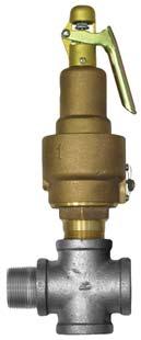
39 î Valve Parts Lists î 1" Auto Air Valve PB VALVE, AUTO AIR, 1", (NORMALLY CLOSED) PB VALVE, AUTO AIR, 1/2", 3/4" & 1", REPAIR KIT INCLUDES # 1, 2, 3, 5, 7, 11, 13, 20 & PB VENT, 1/8" 39


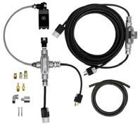
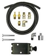
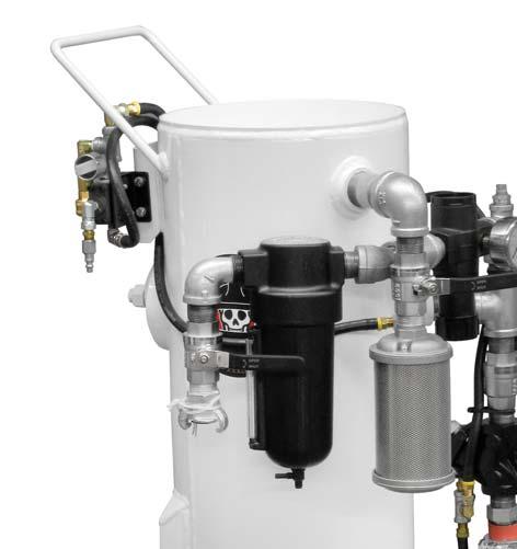
40 î Blasting Set-Up î 40


41 î Blasting Set-Up î Air Dryers / Moisture Separators NOVA PB PB MOISTURE SEPARATOR 800 CFM, PORTABLE 150 PSI (10.3 BAR), (1) 4 LUG W/BALL VALVE INLET x (1) 4 LUG OUTLET AIR DRYER ADPB PSIG OR PSIG ASTRO 41


42 î Available Accessories î A E F SPH G SPR H PNEUMATIC C B D ELECTRIC Palm-BUTTON 42
User s Manual. 3.5 & 6.5 Cu Ft - EPH / EPR SERIES BLASTERS. Read Manual. Manual P/N: PB-MAE001
 User s Manual 3.5 & 6.5 Cu Ft - EPH / EPR SERIES BLASTERS These products and equipment are not under any circumstances to be used with sand or silica products of any type and use of such materials will
User s Manual. Read Manual 3.0 / CPR SERIES BLASTERS. Manual P/N: PB-MAC001
 User s Manual 3.0 / 6.0 - CPR SERIES BLASTERS These products and equipment are not under any circumstances to be used with sand or silica products of any type and use of such materials will void any warranty.
INSTRUCTION MANUAL & PARTS
 PORTABLE PRESSURE BLASTER Models 6-66 With systems RC-76, RC-86 and Dual older VERSIONs ( legs) lg Serie INSTRUCTION MANUAL & PARTS 07-06-6 Table of contents Page Definition of Terms Used In This Manual...
Pirate Brand. Conversion Kits FOR SMALL AND BULK ABRASIVE BLASTERS. Proudly Distributed By: Product Line Brochure. Rev. May 12
 Pirate Brand Conversion Kits F SMALL AND BULK ABRASIVE BLASTERS Proudly Distributed By: Product Line Brochure Rev. May 12 What Can Pirate Brand Do For You? Convert Your Old System If you have a blaster
Pirate Brand. E-Series 3.5 / 6.5 CU FT - ABRASIVE BLASTERS. Proudly Distributed By: Product Line Brochure. Rev. Mar 14
 Pirate Brand E-Series 3.5 / 6.5 CU FT - ABRASIVE BLASTERS Proudly Distributed By: Product Line Brochure Rev. Mar 14 Bag-Breaker/Screen or Optional Umbrella All E-Series portable blasters come standard
Pirate Brand. S-Series 1.5 / 3.5 / 6.5 CU FT - ABRASIVE BLASTERS. Proudly Distributed By: Product Line Brochure. Rev. June 12
 Pirate Brand S-Series 1.5 / 3.5 / CU FT - ABRASIVE BLASTERS Proudly Distributed By: Product Line Brochure Rev. June 12 Features and Benefits Pressure Release (SPR) or Pressure Hold (SPH), 1.5, 3.5 or cu.
PRODUCT OPERATING MANUAL
 PRODUCT OPERATING MANUAL PANBLAST TM BP110 3 BLAST POT Manual Number: ZVP PC 0155 00 SECTION 1. GENERAL INFORMATION 2. INITIAL SETUP INSTRUCTIONS 3. OPERATING INSTRUCTIONS 4. MAINTENANCE 5. TROUBLE SHOOTING
PRODUCT OPERATING MANUAL
 PRODUCT OPERATING MANUAL PANBLAST TM BP50 3 BLAST POT Manual Number: ZVP PC 0156 00 SECTION 1. GENERAL INFORMATION 2. INITIAL SETUP INSTRUCTIONS 3. OPERATING INSTRUCTIONS 4. MAINTENANCE 5. TROUBLE SHOOTING
PRODUCT OPERATING MANUAL
 PRODUCT OPERATING MANUAL PANBLAST TM BP300-1 BLAST POT Manual Number: ZVP-PC-PB-0014 SECTION 1. GENERAL INFORMATION 2. INITIAL SETUP INSTRUCTIONS 3. OPERATING INSTRUCTIONS 4. MAINTENANCE 5. TROUBLE SHOOTING
PRODUCT OPERATING MANUAL
 PRODUCT OPERATING MANUAL PANBLAST TM BP600 3 BLAST POT Manual Number: ZVP PC 0154 00 SECTION 1. GENERAL INFORMATION 2. INITIAL SETUP INSTRUCTIONS 3. OPERATING INSTRUCTIONS 4. MAINTENANCE 5. TROUBLE SHOOTING
PRODUCT OPERATING MANUAL
 PRODUCT OPERATING MANUAL PANBLAST TM BP600 1 BLAST POT Manual Number: ZVP PC 0157 00 SECTION 1. GENERAL INFORMATION 2. INITIAL SETUP INSTRUCTIONS 3. OPERATING INSTRUCTIONS 4. MAINTENANCE 5. TROUBLE SHOOTING
36-1 DP PLEASE READ BEFORE USING THIS EQUIPMENT
 36-1 DP PLEASE READ BEFORE USING THIS EQUIPMENT DP 36-1 Assembly Instructions PLEASE READ INSTRUCTIONS COMPLETELY BEFORE STARTING We thank you for purchasing the DP-36 pressure system. This system has
MODEL G300 BRAKE BLEEDER
 MODEL G300 BRAKE BLEEDER Installation, Operation & Repair Parts Information Branick Industries, Inc. 4245 Main Avenue P.O. Box 1937 Fargo, North Dakota 58103 REV120716 P/N: 81-0035H THIS PAGE INTENTIONALLY
HALLMARK INDUSTRIES INC
 Performance Part No. HP. CONVERTIBLE JET PUMP USER S MANUAL GPH of Water @ Total Discharge Pressure of 40 psi Max. Pressure Max suction (shallow well) Max Suction (deep well) Max GPM (@0 head) Max Discharge
HYDRAULIC BOAT JACK SYSTEM OWNER S MANUAL
 PLEASE READ CAREFULLY: Read and understand the entire contents of this manual with special emphasis on safety precautions before operating the equipment. Do not allow personnel to operate this equipment
Model 1100 Turbine Flow Meter
 Model 1100 Turbine Flow Meter INSTALLATION & INSTRUCTION MANUAL 8635 Washington Avenue Racine, Wisconsin 53406 Tel: 800-433-5263 or 262-639-6770 Fax: 800-245-3569 or 262-639-2267 www.hedland.com TABLE
Hydraulic Truck Jack
 Operating Instructions & Parts Manual Hydraulic Truck Jack Model Capacity 23221C 22 Ton 23222C (Low Profile) 22 Ton 23301 30 Ton Models 23221C & 23222C Model 23301! U.S. Patent No's. 5,341,723 & 5,94,912
Pressure Roller with 24-inch Fixed Extension - For application of architectural paints and coatings -
 Instructions Important Safety Instructions Read all warnings and instructions in this manual. Save these instructions. 311082D Pressure Roller with 24-inch Fixed Extension - For application of architectural
PRESSURE CABINETS PROBLEM CAUSE SOLUTION
 BLAST CABINET TROUBLESHOOTING Page 1 PRESSURE CABINETS 1. Poor Visibility. Motor rotating backwards. The motor should rotate as indicated by the arrow on the housing. If it does not rotate in the proper
PRODUCT OPERATING MANUAL
 PRODUCT OPERATING MANUAL PANBLAST TM CS37 SUCTION BLAST CABINET Manual Number: ZVP PC 0069 00 SECTION 1. GENERAL INFORMATION 2. ASSEMBLY & INSTALLATION INSTRUCTIONS 3. OPERATING INSTRUCTIONS 4. MAINTENANCE
ABRASIVES INC BUYERS GUIDE TABLE OF CONTENTS. This document contains one section of the complete Buyers Guide
 ABRASIVES INC BUYERS GUIDE TABLE OF CONTENTS This document contains one section of the complete Buyers Guide PIRATE AIR BLAST EQUIPMENT & PARTS... SECTION 5 BLAST POTS... 147-159 VALVES... 160-168 1.5,
Tools, Equipment and Supplies Needed:
 153-162 DISC BRAKE/DUAL MASTER CYLINDER CONVERSION Please take the time to read the enclosed instructions carefully. If you have any questions, call our Product Assistance personnel for clarifi cation.
18 KG MOBILE SODA BLASTING UNIT
 OWNER S MANUAL PRODUCT CODE: 3043 18 KG MOBILE SODA BLASTING UNIT Working Air Hose Tank Volume Overall Dimensions Pressure Consumption Length 18KG 35 90psi 6-12CFM 2400mm 460 x 305 x 660 Made in China
MACHINES / RECLAIMS WITH DUST BAG
 WARNING SET-UP INSTRUCTIONS MACHINES / RECLAIMS WITH DUST BAG *** READ BEFORE OPERATING EQUIPMENT *** 1. Remove plastic from machine. 2. Remove lag bolts from each of the four legs, then remove machine
PRODUCT OPERATING MANUAL
 PRODUCT OPERATING MANUAL PANBLAST TM CONEBLAST ½ INTERNAL PIPE TOOL Manual Number: ZVP PC 0179 00 SECTION 1. GENERAL INFORMATION 2. INTRODUCTION 3. INITIAL SETUP INSTRUCTIONS 4. OPERATING INSTRUCTIONS
UR007 UR007-YEXP UR007-YJ UNI-RAM CORPORATION ONTARIO CANADA
 USER MANUAL RECLAIMING SAND BLASTERS MODELS UR007 UR007-YEXP UR007-YJ UNI-RAM CORPORATION ONTARIO CANADA Revised 2010-03 CONTENTS INTRODUCTION... 3 CAUTIONS AND WARNINGS... 3 PREPARATION... 4 NOTES ON
OWNER S MANUAL SELF-PRIMING PORTABLE UTILITY PUMP
 Model 54011-0 OWNER S MANUAL SELF-PRIMING PORTABLE UTILITY PUMP Questions, problems, missing parts? Before returning to the store call AQUAPRO Customer Service 8 a.m. - 5 p.m., EST, Monday-Friday 1-844-242-2475
OPERATOR S MANUAL BLASTMASTER 6.5 CU. FT. HP-SERIES ABRASIVE BLASTING POT
 OPERATOR S MANUAL BLASTMASTER 6.5 CU. FT. HP-SERIES ABRASIVE BLASTING POT Before using this equipment, read, understand and follow all instructions in the Operator s Manuals provided with this equipment.
INSTALLATION AND MAINTENANCE MANUAL FORM #PM-126 REV A 12/09
 HAND CRANK & MOTORIZED POWER CORD REELS: SERIES 1125PC SERIES: 1125PC HAND CRANK SERIES: 1125PC MOTORIZED COXREELS The technical data and images which appear in this manual are for informational purposes
Pro Shot Grease Dispense Valve
 Instructions Parts List Pro Shot Grease Dispense Valve 309032J For high pressure grease dispense. 8000 psi (55 MPa, 552 bar) Maximum Working Pressure Model No. 242055, Series B, 1/4 npt Fluid Inlet Model
BOGERT HMMWV LIFTING JACK KIT PART NR: 30M-HVBMI NSN:
 BOGERT HMMWV LIFTING JACK KIT PART NR: 30M-HVBMI NSN: 5120-01-573-3382 Tire Replacement Jack Operating Instructions Model: 30M-HV Jack with BMI P40A Hydraulic Pump Bogert International Inc. 3606 N. Swallow
Lubricator Gun: 10,000 psi (700 bar) Maximum Delivery Pressure when disconnected from Dispenser
 Maximum Delivery Pressure when disconnected from Dispenser") INSTRUCTIONS-PARTS LIST 30 455 INSTRUCTIONS This manual contains important warnings and information. READ AND KEEP FOR REFERENCE. Rev. C Supercedes B Hand-Operated Portable Grease Dispenser Buckshot Luber
INSTRUCTIONS-PARTS LIST 30 455 INSTRUCTIONS This manual contains important warnings and information. READ AND KEEP FOR REFERENCE. Rev. C Supercedes B Hand-Operated Portable Grease Dispenser Buckshot Luber
Caution. Do not operate your Micro Rain traveler without a serious overview of this manual. Keep children and unauthorized people away from traveler
 Thank you for purchasing a Micro Rain MR25 traveling sprinkler system. Please read this manual carefully before operation in order to become familiar with all components and their function. Safety is the
ORIGINAL INSTRUCTIONS G715A. Pneumatic-hydraulic Riveter E. Warner Ave Santa Ana, CA
 ORIGINAL INSTRUCTIONS G715A Pneumatic-hydraulic Riveter 1224 E. Warner Ave Santa Ana, CA 92705 www.cherryaerospace.com DESCRIPTION The Cherry G715A Pneumatic-Hydraulic Riveter is designed specifically
PB900-GT SLOTBLASTER D-A PLEASE READ BEFORE USING THIS EQUIPMENT
 PB900-GT SLOTBLASTER 101760D-A PLEASE READ BEFORE USING THIS EQUIPMENT PB900-GT Assembly Instructions PLEASE READ INSTRUCTIONS COMPLETELY BEFORE STARTING We thank you for purchasing the PB900-GT pressure
HIGH PRESSURE CONTROL VALVE PISTON BALANCED
 PISTON BALANCED All Rights Reserved. All contents of this publication including illustrations are believed to be reliable. And while efforts have been made to ensure their accuracy, they are not to be
18 GAUGE FLOORING STAPLER. Models: /13
 18 GAUGE FLOORING STAPLER Models: 7560 CALIFORNIA PROPOSITION 65 WARNING: You can create dust when you cut, sand, drill or grind materials such as wood, paint, metal, concrete, cement, or other masonry.
StormPro BA Series Sump Pump
 Page 1 of 8 Marks & Meanings DANGER: Keep the pump equipment out of the reach of children! Warns that the failure to follow the directions given could cause serious risk to individuals or objects. WARNING:
110 Volt/12 Volt Portable Inflator
 110 Volt/12 Volt Portable Inflator Owner s Manual WARNING: Read carefully and understand all ASSEMBLY AND OPERATION INSTRUCTIONS before operating. Failure to follow the safety rules and other basic safety
SAVE THIS MANUAL AND MAKE AVAILABLE TO ALL USERS OF THIS EQUIPMENT!
 SAVE THIS MANUAL AND MAKE AVAILABLE TO ALL USERS OF THIS EQUIPMENT! Manual Part Number 7200-220 AXXIOM Manufacturing, Inc. 11927 S. Highway 6, Fresno, Texas 77545 800.231.2085 * 281.431.0581 * fax 281.431.1717
DeZURIK 2 20" BOS BUTTERFLY VALVES
 2 20" BOS BUTTERFLY VALVES Instruction D10459 October 2013 2-20 BOS Butterfly Valves Instructions These instructions provide information about BOS Butterfly Valves. They are for use by personnel who are
SUPERSPOOL II VALVE PNEUMATIC DIRECTIONAL CONTROL VALVE SERVICE INFORMATION
 SUPERSPOOL II VALVE PNEUMATIC DIRECTIONAL CONTROL VALVE SERVICE INFORMATION Part Number R431001089 (replaces P -030625-00002) Part Number R431001090 (replaces P -030625-00003) under pressure. Always exhaust
Operating Instructions & Parts Manual. Air/Manual Hydraulic Bottle Jacks
 J18124-M1_032015 Operating Instructions & Parts Manual Air/Manual Hydraulic Bottle Jacks Model J18124 J18204 Capacity 12 Ton 20 Ton U.S. Patent Nos. 6,012,377-5,946,912! This is the safety alert symbol.
MODEL 5500 Tire Repair Station
 MODEL 5500 Tire Repair Station Installation, Operation and Repair Parts Information Branick Industries, Inc. 4245 Main Ave P.O. Box 1937 Fargo, North Dakota 58103 P/N: 81-0047C TABLE OF CONTENTS SAFETY
SPECIFICATIONS Horsepower: 1.5 HP Running Maximum PSI: 125 PSI Tank Capacity: 15 Gallons CFM: 6 40 PSI 5 90 PSI
 15 GALLON AIR COMPRESSOR Model: 7678 DO NOT RETURN TO STORE Please call 800-348-5004 for parts and service CALIFORNIA PROPOSITION 65 WARNING: You can create dust when you cut, sand, drill or grind materials
MODEL 7400 STRUT SPRING COMPRESSOR
 MODEL 7400 STRUT SPRING COMPRESSOR Installation, Operation & Repair Parts Information Branick Industries, Inc. 4245 Main Avenue P.O. Box 1937 Fargo, North Dakota 58103 REV112712 P/N: 81-0103A TABLE OF
STOP CITY PRESSURE BOOSTER PUMP INSTRUCTION MANUAL
 CITY PRESSURE BOOSTER PUMP INSTRUCTION MANUAL MODEL #VP05, VP10 C US NSF/ANSI 372 255405 For loose, missing or damaged parts, or if the unit does not seem to be operating properly, please call before returning
User s Manual and Operating Instructions
 User s Manual and Operating Instructions Model Numbers: CL-36-BDF-A, CL-42-BDF-A, CL-48-BDF-A E355088 READ AND SAVE THESE INSTRUCTIONS IMPORTANT: Read and understand all of the instructions in this manual
Operating Instructions for the. In Line Conveyor System West Cabot Boulevard Langhorne, PA w w w.empire-airblast.
 Operating Instructions for the IL-885 In Line Conveyor System 2101 West Cabot Boulevard Langhorne, PA 19047-1893 w w w.empire-airblast.com Model Number: Serial Number: Date of Purchase: Date of Installation:
SPECIFICATIONS CONTENTS: Specifications Warning Information. Operating Instructions Preventative Maintenance Troubleshooting
 Model 3182 2,500 Lbs Power Train Table/Lift OWNER'S MANUAL CONTENTS: Page 1 Page 2-3 Page 3 Page 4 Page 5 Page 5 Page 6 Page 7 Page 8 Specifications Warning Information Setup Operating Instructions Preventative
Container Fountain Kit with LED Light
 Container Fountain Kit with LED Light REMINDER CALL 1-888-755-6750 BEFORE RETURNING TO STORE. PACKAGE CONTENTS Questions, problems, missing parts? Before returning to your retailer, call our customer service
1. CONDITIONS FOR USE 2. SAFETY
 1. CONDITIONS FOR USE This micro abrasive blaster may only be operated: Indoors; Below 6500 ft above sea level altitude; Ambient air temperature between 40-105 F (5-40 C); Maximum relative humidity of
Air-Operated Waste Oil Drainer
 Air-Operated Waste Oil Drainer 20-Gallon Tank Owner s Manual WARNING: Read carefully and understand all ASSEMBLY AND OPERATION INSTRUCTIONS before operating. Failure to follow the safety rules and other
Air Actuated Hydraulic Bottle Jacks
 Air Actuated Hydraulic Bottle Jacks Operating Instructions & Parts Manual Model Number Atd-7412 Atd-7420 Capacity 12 Ton 20 Ton Atd Tools Inc. 160 Enterprise Drive, Wentzville MO 63385 Printed in China
CRD610 Automatic Fitting Inserter
 CRD610 Automatic Fitting Inserter OPERATIONS MANUAL VERSION 1.2 LAST EDITED 12.12.2018 cleanroomdevices.com 1 Table of Contents Title Page. 1 Table of Contents...2 1.0 General Product & Safety Information....3
FIGURE 310A & 311A 3-PIECE BALL VALVE
 INTRODUCTION This instruction manual includes installation, operation and maintenance information for the figure 310A, 310ASW, 311A, and 311ASW 3-piece 1000CWP, threaded end (NPT) or socket weld end (SW)
MODEL L/R/EF Sectional Tire Spreader
 MODEL L/R/EF Sectional Tire Spreader Installation, Operation & Repair Parts Information Branick Industries, Inc. 4245 Main Avenue P.O. Box 1937 Fargo, North Dakota 58103 REV08032016 P/N: 81-0195E TABLE
SUNC3000 / Item #40885
 SUNC3000 / Item #40885 AUTOMATIC POOL COVER PUMP OPERATIONS MANUAL WWW.SUNRUNNERPOOL.COM 1 . Performance GPH of Water @ Total Feet Of Lift MODEL HP Max. Lift 0 ft. 5 ft. 10 ft. 15 ft. 20 ft. SUNC3000 1/3
CLEAN ROOM DEVICES, LLC "WHERE TUBING AND FITTINGS COME TOGETHER"
 CLEAN ROOM DEVICES, LLC "WHERE TUBING AND FITTINGS COME TOGETHER" CRD600 Automatic Fitting Inserter OPERATIONS MANUAL VERSION 2.1 LAST EDITED 7.25.14 DOCUMENT NUMBER 001 cleanroomdevices.com 1 Table of
GBP784B INSTALLATION TOOL
 GBP784B INSTALLATION TOOL GAGE BILT MADE IN U.S.A. GAGE BILT PRODUCTS CORP. 14500 Barber Drive (586) 771-7664 Warren, Mi 48088 (586) 771-2665 Fax e-mail:solutions@gagebilt.com / www.gagebilt.com TABLE
Air Control Kit INSTRUCTIONS-PARTS LIST. Table of Contents HIGH VOLUME. 250 psi (1.7 MPa, 17.2 bar) Maximum Air Inlet Pressure
 Maximum Air Inlet Pressure") INSTRUCTIONS-PARTS LIST INSTRUCTIONS This manual contains important warnings and information. READ AND KEEP FOR REFERENCE. 308 648 Rev. B Supersedes A HIGH VOLUME Air Control Kit 250 psi (.7 MPa, 7.2 bar)
INSTRUCTIONS-PARTS LIST INSTRUCTIONS This manual contains important warnings and information. READ AND KEEP FOR REFERENCE. 308 648 Rev. B Supersedes A HIGH VOLUME Air Control Kit 250 psi (.7 MPa, 7.2 bar)
Clevis Plunger & Base Instruction Manual
 MODELS: CED09 & CED16 SFA Companies 10939 N. Pomona Ave. Kansas City, MO 64153 Tel: 888-332-6419 - Fax: 816-448-2142 E-mail: sales@bvahydraulics.com Website: www.bvahydraulics.com CED09-M0_102017 Clevis
Electronic Timer Drain and Filter Ball Valves. Operating Instructions Manual
 Operating Instructions Manual EN Electronic Timer Drain and Filter Ball Valves Models 12F742, 13X522-13X542, 38UC76, 38UC77, 38XR36, 38XR45, 38XR46, 38XR59, 38XR65, 38XR70, 38XR85, 38XT18, 38XT31, 38XT33,
LUBRICATOR GUN INSTRUCTIONS-PARTS LIST. 10,000 psi (700 bar) Maximum Delivery Pressure. Detachable-type
 Maximum Delivery Pressure. Detachable-type") INSTRUCTIONS-PARTS LIST 306 460 INSTRUCTIONS This manual contains important warnings and information. READ AND KEEP FOR REFERENCE. Rev. E Supercedes D Detachable-type LUBRICATOR GUN 10,000 psi (700 bar)
INSTRUCTIONS-PARTS LIST 306 460 INSTRUCTIONS This manual contains important warnings and information. READ AND KEEP FOR REFERENCE. Rev. E Supercedes D Detachable-type LUBRICATOR GUN 10,000 psi (700 bar)
MODEL G300 Brake Bleeder
 MODEL G300 Brake Bleeder Installation, Operation & Repair Parts Information Branick Industries, Inc. 4245 Main Avenue P.O. Box 1937 Fargo, North Dakota 58103 Rev013107 P/N: 81-0035C CAUTION Before using
 Operation and Maintenance Manual http://www.torsionx.eu Use the MaxDrv Series Square Drive Torque Wrench Model.75, 1, 3, 5, 8, 10, 20, 25, 35, 50 to install and remove threaded fasteners requiring precise
DISC BRAKE/DUAL MASTER CYLINDER CONVERSION. Tools, Equipment and Supplies Needed:
 Please take the time to read the enclosed instructions carefully. If you have any questions, call our Product Assistance personnel for clarification. It is important to note that these instructions contain
PNEUMATIC ABRASIVE CONVEYORS MODELS 16-PAC, 24-PAC, 30-PAC AND 36-PAC O.M MC FILE NUMBER: DATE OF ISSUE: 2/15/78 REVISION: C, 02/92
 PNEUMATIC ABRASIVE CONVEYORS MODELS 16-PAC, 24-PAC, 30-PAC AND 36-PAC O.M. 04117 MC FILE NUMBER: 145-1177 DATE OF ISSUE: 2/15/78 REVISION: C, 02/92 NOTICE TO PURCHASERS AND USERS OF OUR PRODUCTS AND THIS
Water Sandblaster Kit
 a Instructions - Parts List Important Safety Instructions Read all warnings and instructions in this manual. Save these instructions. Water Sandblaster Kit 308544 - For suction fed injection of sand into
AEROMOTIVE Part # Generic EFI Fuel System INSTALLATION INSTRUCTIONS
 AEROMOTIVE Part # 17150 Generic EFI Fuel System INSTALLATION INSTRUCTIONS CAUTION: Installation of this product requires detailed knowledge of automotive systems and repair procedures. We recommend that
Premium Supply. Direct Push. Models PCK-3530-DP PCK DP PCK-530-DP. Operator s Manual and Installation Instructions
 Direct Push Models PCK-3530-DP PCK-3530-2DP PCK-530-DP Operator s Manual and Installation Instructions Premium Supply 2038 West Interstate 30 866-934-0777 Proud members of: and June 20, 2018 Table of Contents
AEROMOTIVE Part # and F-Body Fuel System Kit INSTALLATION INSTRUCTIONS
 AEROMOTIVE Part # 17101 and 17102 93-97 F-Body Fuel System Kit INSTALLATION INSTRUCTIONS CAUTION: Installation of this product requires detailed knowledge of automotive systems and repair procedures. We
AEROMOTIVE Part # Generic Fuel System Kit INSTALLATION INSTRUCTIONS
 AEROMOTIVE Part # 17242 Generic Fuel System Kit INSTALLATION INSTRUCTIONS CAUTION: Installation of this product requires detailed knowledge of automotive systems and repair procedures. We recommend that
Getz Equipment Innovators 450 lb Portable / Wheeled Unit Dry Chemical Fill System Part No: 3G0061/3G0063
 Getz Equipment Innovators 450 lb Portable / Wheeled Unit Dry Chemical Fill System Part No: 3G0061/3G0063 1 Revised 4/12/17 2320 Lakecrest Drive, Pekin IL 61554 PH. (888) 747-4389 Fax (309) 495-0625 Website:
SUBMERSIBLE SUMP PUMPS
 SUBMERSIBLE SUMP PUMPS Zoeller is a registered trademark of Zoeller Co. All Rights Reserved. MODELS #1073-0001, 1075-0001 Español p. 9 ATTACH YOUR RECEIPT HERE Serial Number Purchase Date Questions, problems,
MODEL 7600 STRUT SPRING COMPRESSOR
 MODEL 7600 STRUT SPRING COMPRESSOR Installation, Operation & Repair Parts Information Branick Industries, Inc. 4245 Main Avenue P.O. Box 1937 Fargo, North Dakota 58103 REV6162014 P/N: 81-0246 TABLE OF
p.t.o. Slip clutch Read this material before using this product. Failure to do so can result in serious injury. Save this manual.
 p.t.o. Slip clutch 65517 Installation Instructions Distributed exclusively by Harbor Freight Tools. 3491 Mission Oaks Blvd., Camarillo, CA 93011 Visit our website at: http://www.harborfreight.com Read
High Pressure Abrasive Blast Cabinet 42000
 Please read and save these instructions. Read through this owner s manual carefully before using product. Protect yourself and others by observing all safety information, warnings, and cautions. Failure
Customer Support
 Portable auxiliary air tanks owner's Manual aux05 aux05a aux10 WWW.CALIFORNIAAIRTOOLS.COM Customer Support 1-866-409-4581 TAbLe OF CONTeNTS INTROduCTION IntroductIon Important Safety InStructIonS components
FIGURE 310AM, 310AMSW & 311AM 3-PIECE BALL VALVE
 INTRODUCTION This instruction manual includes installation, operation and maintenance information for the figure 310AM, 310AMSW, and 311AM 3-piece 1000CWP, threaded end (NPT) or socket weld end (SW) ball
OPERATOR S MANUAL BLASTMASTER 130E REMOTE CONTROL SYSTEM
 OPERATOR S MANUAL BLASTMASTER 30E REMOTE CONTROL SYSTEM Before using this equipment, read, understand and follow all instructions in the Operator s Manuals provided with this equipment. If the user and/
Heavy-Duty Welding Fabrication Table
 Heavy-Duty Welding Fabrication Table with Fix-Up Kit Owner s Manual WARNING: Read carefully and understand all ASSEMBLY AND OPERATION INSTRUCTIONS before operating. Failure to follow the safety rules and
Adjustable Steel Welding Table
 Adjustable Steel Welding Table Owner s Manual WARNING: Read carefully and understand all ASSEMBLY AND OPERATION INSTRUCTIONS before operating. Failure to follow the safety rules and other basic safety
Operating Manual. FloorMaster FS Flooring Stapler A18201 READ ALL SAFETY INSTRUCTIONS
 Operating Manual FloorMaster FS Flooring Stapler READ ALL SAFETY INSTRUCTIONS items included with tool INCLUDED WITH TOOL Plastic Case Tool Manual Safety Glasses Pneumatic Tool Oil Hex Key x 3 ACCESSORIES
AEROMOTIVE Part # Generic Fuel System Kit INSTALLATION INSTRUCTIONS
 AEROMOTIVE Part # 17125 Generic Fuel System Kit INSTALLATION INSTRUCTIONS CAUTION: Installation of this product requires detailed knowledge of automotive systems and repair procedures. We recommend that
D Instructions/Parts. Siphon Feed Detail Spray Gun D
 Instructions/Parts D-5-55 Siphon Feed Detail Spray Gun FOR PRODUCT INFORMATION CALL: 1-800-742-7731 309991D Important Safety Instructions Read all warnings and instructions in this manual. Save these instructions.
CRD600 Automatic Fitting Inserter
 CRD600 Automatic Fitting Inserter OPERATIONS MANUAL VERSION 2.3 LAST EDITED 12.07.2018 cleanroomdevices.com 1 Table of Contents Title Page.. 1 Table of Contents. 2 1.0 General Product & Safety Information...3
Rapid Shrink 100. Owner s Manual
 Rapid Shrink 100 Owner s Manual Table of Contents Introduction Pg. 2 General Safety Pg. 3-4 Which Tank to Use Pg. 5-6 Operating Instructions Pg. 7-10 Troubleshooting Guide Pg. 11-12 Parts Index Pg. 13-14
2-in-1 Air Operated Waste Oil Drainer
 2-in-1 Air Operated Waste Oil Drainer 24-Gallon Tank Owner s Manual WARNING: Read carefully and understand all ASSEMBLY AND OPERATION INSTRUCTIONS before operating. Failure to follow the safety rules and
SBCNNS. Abrasive Blast Cabinet Assembly & Operating Instructions
 SBCNNS Abrasive Blast Cabinet Assembly & Operating Instructions READ ALL INSTRUCTIONS AND WARNINGS BEFORE USING THIS PRODUCT. This manual provides important information on proper operation & maintenance.
Mini Jacks Instruction Manual
 J11050-M0_062017 Instruction Manual MODELS: J11050, J11055-5 Ton Capacity J11100-10 Ton Capacity J11200-20 Ton Capacity This is the safety alert symbol. It is used to alert you to potential personal injury
OPERATING INSTRUCTIONS AND PARTS MANUAL
 Assembled in USA WARNING ATENCION ATTENTION OPERATING INSTRUCTIONS AND PARTS MANUAL 89143380-2 For technical assistance or the Dealer nearest you, call (360) 833-1600 8.914-338.0 2 CONTENTS Introduction...
AUTOMATIC SUBMERSIBLE UTILITY PUMP
 AUTOMATIC SUBMERSIBLE UTILITY PUMP Zoeller is a registered trademark of Zoeller Co. All Rights Reserved. MODEL #1043-0006 Español p. 9 ATTACH YOUR RECEIPT HERE Serial Number Purchase Date Questions, problems,
Model GP Triplex Ceramic Plunger Pump Operating Instructions/ Manual
 Model GP6145-3100 Triplex Ceramic Plunger Pump Operating Instructions/ Manual Contents: Installation Instructions: page 2 Pump Specifications: page 3 Exploded View: page 4 Parts List / Kits: page 5 Repair
AEROMOTIVE Part # & Generic Fuel System Kit INSTALLATION INSTRUCTIONS
 AEROMOTIVE Part # 17135 & 17136 Generic Fuel System Kit INSTALLATION INSTRUCTIONS CAUTION: Installation of this product requires detailed knowledge of automotive systems and repair procedures. We recommend
INSTRUCTIONS PARTS LIST This manual contains important warnings and information. READ AND RETAIN FOR REFERENCE
 INSTRUCTIONS PARTS LIST 308 493 This manual contains important warnings and information. READ AND RETAIN FOR REFERENCE Rev. A Second Gun Hose Kit 100 psi (6.9 bar) Maximum Working Pressure These kits include
Hydraulic Long Jacks
 Operating Instructions & Parts Manual Hydraulic Long Jacks Model 44915 44930 44940 44980 44981C (Air option) Capacity 1-1/2 Ton 3 Ton 4 Ton 8 Ton 8 Ton Models 44915, 44930, 44940 & 44980 Model 44981C U.S.
Pipe fi ttings MUST be installed by a certifi ed welder only. Signet will not assume liability of any kind for improper fi tting installations.
 Signet 50 High Performance Flow Sensor English *3-50.090* 3-50.090 C 05/06 English SAFETY INSTRUCTIONS 1. Do not remove from pressurized lines.. Do not exceed maximum temperature/pressure specifi cations.
P5510. Users Manual. Pneumatic Comparison Test Pump
 P5510 Pneumatic Comparison Test Pump Users Manual PN 3952297 November 2010 2010 Fluke Corporation. All rights reserved. Printed in USA. Specifications are subject to change without notice. All product
Hydraulic Transmission Jack, Telescopic
 Operating Instructions & Parts Manual Hydraulic Transmission Jack, Telescopic Model 4000 400 (Air Operated) Capacity 000 lbs. 000 lbs. Model 4000 Model 400 U.S. Patent No. 6,02,377! This is the safety