Installation, Operations & Maintenance
|
|
|
- Osborn Watkins
- 5 years ago
- Views:
Transcription


1 Cleanawater TS2000 SS Oil Water Separator 2000 L/hr Installation, Operations & Maintenance cleanawater.com.au
2 TABLE OF CONTENTS COMPANY INFORMATION 2 PARTS INCLUSION LIST 3 PRODUCT INFORMATION 4 SYSTEM SPECIFICATIONS 6 TYPICAL INSTALLATION SCHEMATIC 7 INSTALLATION INSTRUCTIONS 12 FINAL INSTALLATION CHECKLIST 17 OPERATIONS & MAINTENANCE GUIDE 18 OPERATIONS GUIDE 18 MAINTENANCE GUIDE 18 WEEKLY MAINTENANCE 18 QUARTERLY MAINTENANCE 19 WARRANTY TERMS 20 TROUBLESHOOTING GUIDE 21 CLEANAWATER TERMS & CONDITIONS 26 PUMP MANUALS & CONNECTION DIAGRAMS REAR 1

3 COMPANY INFORMATION Water Sustainability is a key to our economic and environmental future As one of Australia's leading providers of water treatment and recycling solutions; Cleanawater is committed to building a sustainable future. Since 1996 our technologies have been helping businesses achieve cleaner water solutions that are both cost effective and authority and regulatory compliant. Cleanawater is a 100% Australian owned and operated water technology company that has been providing water treatment and recycling solutions throughout Australasia for over 17 years. Our manufacturing and research and development centre are based out of our head office in Thomastown, Victoria, with offices located in Brisbane, Perth and Adelaide. Our product range includes: Largest Range of Oil Water Separators Coalescing, VGS, Hydrocyclone and Induced Cyclonic Separators Water Recycling Systems First Flush Diversion / Stormwater Management Systems Rainwater Harvesting Systems AQIS Treatment Systems Packaged Pumping Stations ph & Chemical Control Systems Oil Skimmers floating oil skimmers / belt oil skimmers 2
4 PARTS INCLUSION LIST Your package should include the following items. Please check these items off as received. If any items are missing please contact Cleanawater on Note: If your package is a non-standard package additional/other items may be included in your package. Item Qty Included (Y/N) Oil Separator TS2000 SS oil water separator unit & lid stainless steel 1 Galvanized OR stainless steel support frame 1 DN40 ball valve 2 DN40 sludge outlet nipple 2 DN40 internal sludge outlet elbow factory fitted 2 DN50 internal waste water outlet elbow factory fitted 1 Coalescing Media Packs factory fitted 3 Media Packs support grid factory fitted 4 Inlet splash guard factory fitted 1 Adjustable Waste Oil Collar factory fitted (not adjusted) 1 DN40 rubber 90 degree elbow & PVC waste oil outlet pipe 1 Stainless steel worm drive clip to suit waste oil hose 1 20L waste oil collection drum OR 1000L IBC waste oil tank 1 Installation, operations and maintenance guide 1 Oil Separator Feed Pump(s) Mono CP800 OR KwikFlo KDS Electric Diaphragm Pump (note other models may be included based on availability refer to your pump manual attached for model information) 1 Controls Float Switch with 10m lead working float switch 1 Float Switch with 10m lead high level alarm float switch (optional) 1 Cleanawater pump control panel (refer to pump wiring diagram for all wiring and function information) 1 Optional Extras Other items may be included in your package based on your specific site requirements, refer to your packing slip or contact Cleanawater on for confirmation. 3
5 PRODUCT INFORMATION Cleanawater TS series oil water separators are classified as coalescing type separators (CPS), where oil droplets in suspension in the moving water stream are removed in a coalescing process by the separating media. The separating media in the two stages of the Cleanawater TS separator provides a random packed mass of polypropylene rings with a maximized ratio of surface area to volume. The mass of rings fully occupy the compartments of the two separation stages providing high surface area with the necessary open area to allow the waste water stream to pass through. The random placement of the packing ensures that the waste water cannot channel and avoid passing through the media rings. In the separating process the oil droplets carried in the waste water stream must pass through the maze of polypropylene rings. The gentle flow used, in conjunction with and high surface area and depth of the bed in both compartments, ensures that the majority of oil droplets, however small, impinge on a ring surface. The droplet velocity reduces to zero and gravity takes control. As additional oil droplets impinge on the ring the droplets coalesce together and grow in size. As the droplet volume increases the buoyancy also increases. This increasing buoyancy drives the droplets to top surface. As the oil level grows on the top surface it overflows to a waste oil collection container. Similarly, but in reverse sequence, the solids particles impinge on the ring surfaces and lose their velocity. Gravity will draw them to the base of the unit as their particle size increases. Upon passing through the treatment system, created by the two stage packed media coalescing process, water is now treated and via separator outlet is ready for disposal or to commence next stage of treatment. 4
 at 25 O C f.")
6 Effluent standards for the Cleanawater TS series oil water separators adhere to the WSAA Product Specification WSA PS 810, Separator Systems for Light Liquids as listed below. a. Total Grease 50 mg/l b. Petroleum Hydrocarbons including BTEX 10mg/L c. Benzene 0.1mg/L d. Suspended Solids 200mg/L e. Flammability < 5% LEL (hexane) at 25 O C f. ph 7-10 Note: - Quick break and bio degradable detergents and degreasers should be used in conjunction with the system. - Holding pit capacity should match the hourly throughput of the oil separator system. - Any solvent based liquids or emulsifiers should be avoided, these may affect the efficiency of the unit performance. - Coalescing oil separators are designed to remove free oils and mineral grease only. 5
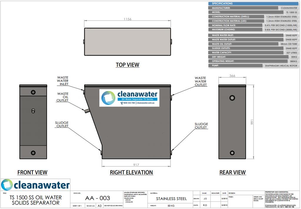
7 SYSTEM SPECIFICATIONS 6
8 TYPICAL INSTALLATION SCHEMATICS Note these may differ depending on your application. Attached are typical installations only. TYPICAL GRAVITY DISCHARGE LAYOUT 7
9 TYPICAL PUMPED DISCHARGE LAYOUT 8
10 INSTALLATION INSTRUCTIONS *-Note: At installation stage, all plumbing works must be completed by a licensed plumber. If electrical works are required to be completed they must be completed by an electrician with relevant certifications. Local water authorities should be contacted prior to installation to ensure local requirements have been met. INSTALLATION PROCEDURES STEP 1 PREPARE AREA FOR INSTALLATION Locate the oil separator in its operating position with sufficient access clearance to operate the sludge drain valves. While doing this also position your waste oil container and ensure reasonable work clearances are maintained. STEP 2 SETTING UP Place unit or support frame on a solid and even base. A level concrete slab is preferred. If the slab is uneven it is preferable to cement slurry the surface and set the separator/frame into the wet cement. STEP 3 SETTING UP If you have been supplied with a separator support stand, dyna bolt your separator support stand into the concrete slab at the four corners of the stand within the holes built into the stand. For corrosive environments ensure galvanized fixing materials are used. Ensure that your foundation has sufficient strength to support the mass of the unit. STEP 4 CHECK FOR A LEVEL SURFACE Ensure that the unit is level within 5 mm on both axes. This can be measured across the top flanges of the unit (with the cover off). STEP 5 PLUMBING CONNECTIONS Pipe the inlet and outlet water connections. All plumbing shall comply to Australian Standard AS
11 Connections as follows should be completed: Collection Pit Pump Inlet Pump Outlet Separator Inlet Separator Outlet Sewer or discharge point *- Refer to specification sheet for unit inlet/outlet sizes, check the manufacturer data sheet for pump inlet and minimum diameter piping requirements to ensure pump warranty is not voided. *- Note: Ensure local piping material standards have been met, any connections to sewer must be completed by a licensed plumber. STEP 6 PLUMBING CONNECTIONS Plumb the suction line to the pump using the correct diameter pipe as recommended from the pit / suction source. Note: It is a requirement in some areas to provide sampling taps on the inlet and outlet pipes of the separator. STEP 7 PLUMBING CONNECTIONS The suction line must be terminated close to the base of the collection pit in line with the recommendations on the typical installation schematic. It is recommended that a barrel union in the suction line is installed to allow for simple future maintenance. A foot valve (Mono pump only) should be installed to the base of the suction line. A strainer should be installed to be base of the suction line if a diaphragm pump is feeding the oil separator. * - Note: If a floating skimmer oil is installed in the sump a foot valve/strainer cannot be installed as a flexible vacuum hose is connected to the pressure pipe directly. STEP 8 PLUMBING CONNECTIONS Fit the supplied gate valve (2) to the sludge outlets. Ensure they are closed before filling the separator. STEP 9 - PLUMBING CONNECTIONS 10
12 Fit the suppled clear PVC hose to the waste oil outlet line, secure using worm drive clip supplied. A 20 litre chemical drum is recommended to be used as a waste oil container to aid in disposal at required date. For mining environments it is suggested a high volume waste oil collection container such as an IBC is used to collect waste oil. STEP 10 PLUMBING CONNECTIONS Plumb the pump to the separator. Barrel unions in the pipes either side of the pump to aid in servicing is recommended. A lute should be plumed in to the line to ensure pump is always primed (for Mono Pumps only). STEP 11 PLUMBING CONNECTIONS Plumb the oil separator outlet to discharge source. Barrel unions in the pipe to aid in servicing is recommended. All discharge pipework must be in accordance with local regulations including any sampling points and tundishes. Check your local plumbing regulations for pipe work requirements. QUALIFIED ELECTRICIANS MUST COMPLETE ANY WIRING STEP 12 ELECTRICAL CONNECTIONS Wire the pump into the electrical controller (Controllers have Manual/Auto/Off functions and are available from Cleanawater; they are designed to be plugged into 240 volt 10amp power points unless specified) Follow the wiring diagram supplied at all times to ensure the pump is not damaged. * - Note - 3 phase pump controllers with additional functions may also be supplied, contact your Cleanawater representative to confirm the model of your pump controller(s). STEP 13 ELECTRICAL CONNECTIONS Install the float switch to deactivate the pump ensuring it has suitable clearance from the suction line inlet level. Refer to supplied wiring diagram at all times. * - Failure to do this will cause problems in your pump to prime. 11
13 Fasten the float switch lead to the suction line with plastic cable ties with care taken to ensure that the float travel is not impeded in any way. The pumping range (switch on point) should be set approximately 500mm from the (switch off point). This can be increased depending on the collection pit storage size. If you have a high level alarm included with your package, repeat this step and set the high level alarm float to trigger near top of your water collection vessel. Refer to supplied wiring diagram at all times. STEP 14 ELECTRICAL CONNECTIONS Strip the float lead back to expose active, neutral and earth wires. Following the wiring instructions, attach the float lead wires to the control panel. Switch on the control panel at the power point and ensure it is switched to the Off setting. Refer to supplied wiring diagram at all times. STEP 15 ADJUST WASTE OIL OVERFLOW OUTLET Fill the oil separator with clean water and ensure pump is primed by using fresh water entered into the pump chamber. Switch the pump control panel to Manual mode ensuring there is enough water in the collection pit to feed the separator, this will pump water into the oil separator unit. Whilst the pump is operating adjust the overflow socket of the Waste Oil Outle to a level 5 mm above the water surface. This overflow socket can be moved up or down the pipe and is sealed by means of an O ring. This socket adjustment should be made while the feed pump is operating as the water level will drop when the pump stops. 12
14 STEP 16 ELECTRICAL CONNECTIONS Switch the pump controller to Auto mode as per included instructions, this will ensure the pump operation is triggered by the float switch activating the pump at a level when water level triggers its operation. Make final adjustments to float level controls ensuring pump switch on and switch off points are suitable. STEP 17 COMPLETION Replace cover, check all connections. Fill unit with fresh water for first start. Refer to installation completion checklist to ensure all items are complete. Refer to operations and maintenance manual to ensure periodic maintenance on the system is completed. 13
15 FINAL INSTALLATION CHECKLIST Refer to the checklist below to ensure your Cleanawater TS series oil separator has been setup correctly. Note: This layout refers to a typical installation only. You may have specific installation instructions provided due to an alternate layout or additional equipment installed for your waste water treatment solution. Contact Cleanawater on for any questions related to installation and or operation of the system. Item Description Placement Unit is installed on flat ground Unit has been fixed to floor surface Pump and oil separator has adequate service access Connections - Plumbing Plumbing connections are completed with all barrel unions tightened including: Checked (Y/N) Connections Electrical Oil Separator operation Sump/Tank pump line to pump inlet Foot valve/strainer fitted to base of pump line in pit Pump inlet to oil separator inlet Waste oil outlet to waste oil drum Ball valves fitted to sludge outlets x 2 Oil separator outlet to discharge source Float switches set at correct on/off heights and wired back to control panel Control panel is mounted and easily accessible Control panel is plugged into mains power point Pump and control floats are wired back to control panel Pump control panel has power on All internal elbows and fittings are fitted and tight Internal media packs and pack holders are in place Pumps are primed in accordance with manufacturer recommendations Unit is filled with fresh water for first start Inlet splash guard is set in place Waste oil overflow outlet is set to 5mm of surface when pump is pumping water into the oil separator Pump controller is set to automatic mode Oil separator lid is placed on top of unit Unit is operational 14
16 OPERATIONS AND MAINTENANCE GUIDE OPERATIONS Once the unit is entered into operation, it is an automated process activated by the float switch in the collection pit which controls water throughput the oil separator; discharge from the oil separator is via gravity into sewer or discharge tank. Pump tanks if pumping to a discharge source can be supplied on request. Maintenance is to be routinely completed to ensure that the system is operating to its designed efficiency. MAINTENANCE The Cleanawater system is a high performance unit capable of separating high levels of hydrocarbons and solids within the waste water stream. To ensure it is operating to the maximum of its efficiency the following maintenance should be completed: WEEKLY MAINTENANCE TASKS a) Inspect silt traps and collection pits, clean as required b) Open oil separator lid, inspect water flow and build up of oils on surface c) When pump is running check water levels in each of the two stages, an even water level in both stages illustrates the system is working correctly. If the water level in the first stage is visibly higher than the second stage a system clean is required immediately, refer to Monthly/Quarterly maintenance procedures d) Check waste oil container for any build up of oil, dispose of any oil in accordance with local regulations e) Check the pump operation, float operation and ensure it is activating when water level reaches trigger point f) Check condition of gate valves to sludge outlets and check any piping for damage 15
17 QUARTERLY MAINTENANCE TASKS a) Refer to Weekly tasks for regular maintenance checks b) Switch pump control panel of Off c) Attach 40mm suction hoses to gate valves at base of unit, open valves to drain water level down, either dispose of waste water by using an EPA authorized contractor or drain back into collection pit (ideally) d) Remove stainless steel grids and separation media packs from unit e) Rinse stainless steel grids and separation media bags with a pressure washer, a light spray will achieve the required result f) Clean out the oil separator using a pressure washer ensuring all walls are clean g) Re-install the separation media packs and stainless steel grids h) Remove suction hoses from sludge valves and close i) Check sludge build up in collection pit, ensure build of sludge is removed periodically j) Fill the system with fresh water k) Switch the pump control panel to Auto and inspect system ensuring it is operational l) Replace lid 16

18 WARRANTY TERMS Pump Warranty Manufacturer s warranty is 12 months from the date of sale unless specified Oil Separator Warranty The Cleanawater oil separator is supplied with a 5 year perforation warranty period in a selection of 304 and 316 stainless steel in non corrosive environments. If any corrosive elements exist within the waste water stream Cleanawater should be contacted to discuss suitability of the separator shell for the environment. Other components All other components that are supplied with the oil separator including the float switch are sold with a 12 month warranty. Compliance Plates Each Cleanawater oil separator has an identification plate, attached to the top right hand corner adjacent to the discharge point. Plate material is aluminium foil with overall dimensions of 120mm x 50mm 17
19 TROUBLESHOOTING GUIDE SYMPTOM/CAUSE PLAN OF ACTION WATER IS NOT FLOWING INTO OIL SEPARATOR Pump is not running Check that there is power to the pump by checking local power source Check that the pump controller is set to manual/auto mode Refer to the supplied wiring diagram that pump connections to the controller are correct Check pump overload switch is not tripped Suction line is obstructed Check pump suction line for obstructions causing blockage Flush suction line with water to remove blockage Inspect suction lines for air ingression/cracks and change if required Check foot valve for obstructions Check suction line is not submersed in sludge build up Pump has lost prime Prime pump chamber in accordance with manufacturer s instructions Check foot valve for obstructions Float switch working level requires adjustment and is set too low. Reset the float level off level to be above the base of the suction line Pump component is damaged Pump diaphragm or rotor stator may be worn, this will cause non suction although you will hear the pump motor running, contact Cleanawater or the pump manufacturer for pump spares Inadequate water level in the sump Water level in the sump has not triggered the working float switch to start the pump, check float is working correctly Float switch working level requires adjustment and is set too low. Reset the float level off level to be above the base of the suction line WATER IS INTERMITTENTLY PUMPING INTO THE OIL SEPARATOR Pump has lost prime Prime pump chamber in accordance with manufacturer s instructions Check foot valve for obstructions Float switch working level requires adjustment and is set too low. Reset the float level off level to be above the base of the suction line 18
20 Check suction line is not submersed in sludge build up Suction Line is obstructed Check pump suction line for obstructions causing blockage Flush suction line with water to remove blockage Inspect suction lines for air ingression/cracks and change as required Check foot valve for obstructions Check suction line is not submersed in sludge build up WATER IS FLOWING INTO WASTE OIL CONTAINER Waste oil collar on the inside of the unit is set too low Ensure there is adequate water level in the pit, switch the pump controller to manual mode to start the pump operation. Adjust the waste oil collar inside the oil separator to be 5mm above water level when the pump is running. This will ensure that only oils separated from the system will be skimmed off into the waste oil drum and no excess water. Switch pump control back to Auto mode when complete. There is a discharge blockage Media packs are blocked and required to be cleaned in accordance with operations and maintenance schedule Note: If it is found that blockage occurs regularly your oil separator system may be undersized or overload of solids are blocking the system, ensure all heavy solids are settled out or suction line is located with adequate clearance from the base of the pit The pump flow rate is rated too high for the oil separator Excess flow rate is pumping through the system, ensure the correct pump is being used in accordance with the separator model, submersible or centrifugal pumps must not be used. WATER IS FLOWING OUT OF THE TOP OF THE OIL SEPARATOR There is a discharge blockage Media packs are blocked and required to be cleaned in accordance with operations and maintenance schedule Note: If it is found that blockage occurs regularly your oil separator system may be undersized or overload of solids are blocking the system, ensure all heavy solids are settled out or suction line is located with adequate clearance from the base of the pit The pump flow rate is rated too high for the oil separator Excess flow rate is pumping through the system, ensure the correct pump is being used in 19
21 accordance with the separator model, submersible or centrifugal pumps must not be used. PUMP IS RUNNING BUT NO WATER IS FLOWING INTO THE OIL SEPARATOR Suction line is obstructed Check pump suction line for obstructions causing blockage Flush suction line with water to remove blockage Inspect suction lines for air ingression/cracks and change as required Check foot valve for obstructions Check suction line is not submersed in sludge build up Pump component is damaged Pump diaphragm or rotor stator may be worn, this will cause non suction although you will hear the pump motor running, contact Cleanawater or the pump manufacturer for pump spares THERE IS NO OIL IN THE WASTE OIL CONTAINER Waste oil collar on the inside of the unit is set too high Ensure there is adequate water level in the pit, switch the pump controller to manual mode to start the pump operation. Then adjust the waste oil collar inside the oil separator to be 5mm above water level when the pump is running. This will ensure that oils separated from the system will be skimmed off into the waste oil drum and not contained within the unit. Switch pump control back to Auto mode when complete. There is little or no oils in the waste water stream The oils in the waste water stream are not free oils or oil droplets in suspension have been emulsified due to use of solvents or other contaminants effecting oil water separation efficiency, coalescing oil separators will efficiently remove free oils and grease from water, emulsified oils cannot be removed and requires secondary filtration. Contact Cleanawater on for further information on correct use of system Ensure that quick break, biodegradable detergents and degreasers are used with the oil separator, mixture with other detergents and degreasers or other contaminants may affect the waste water stream and discharge results PUMP OVERLOAD SWITCH CONTINUES TO TRIP 20
22 Pump motor overheating Pump motor is located in an area with minimal airflow and causing the motor to overheat, relocate motor or remove heat sources to ensure adequate ventilation is available of pump motor Faulty pump motor Pump motor may have defects, contact Cleanawater on or the pump manufacturer for further information Power supply is faulty The pump power supply may have faults or the breaker on the main board may be tripped Ambient temperature conditions high Pump motor is located in an area with minimal airflow and causing the motor to overheat, relocate motor or remove heat sources to ensure adequate ventilation is available of pump motor THE SYSTEM WILL NOT SWITCH ON/OFF No power to pump The pump power supply may have faults or the breaker on the main board may be tripped Check power switch is on to the pump control panel Mode incorrectly set on control panel Refer to wiring diagram and instructions to activate pump controller modes correctly. Manual mode will start the pump manually regardless of the water level in the sump, Auto mode will start the pump on float level switch on point and switch off the pump on float level switch low point. Never leave the pump control mode on manual or you will risk damaging the pump. Overload switch adjustment If applicable your pump controller may have an overload switch adjustment, refer to wiring diagram and instructions for correct adjustment, contact Cleanawater on for further assistance. Float switch is stuck Check float switch levels to ensure they are not entangled or obstructed, flick the switch manually by hand up and down to ensure the pump switches on and off accordingly Float switch failed Check float switch levels to ensure they are not entangled or obstructed, flick the switch manually by hand up and down to ensure the pump switches on and off accordingly. Check float switch wiring connections in pump controller and/or junction box THERE IS OIL PRESENT IN THE DISCHARGE 21
23 Oil spill has occurred or excessive load of oil ingression Oil spillage event or disproportionate loads of oil is pumping through the system, attend to the spillage as soon as possible Contamination of waste water stream Ensure that quick break, biodegradable detergents and degreasers are used with the oil separator, mixture with other detergents and degreasers or other contaminants may affect the waste water stream and discharge results Discharge blockage Media packs are blocked and required to be cleaned in accordance with operations and maintenance schedule THERE IS A SMELL COMING FROM THE PIT OR THE OIL SEPARATOR SYSTEM Pump is not running Check pump operation to ensure pump is switching on/off correctly. Sludge build up in pit or separator Check sump levels for build up of sludge and have pit pumped out regularly Oil separator requires a service in accordance with operations and maintenance manual Stagnant water Run fresh water into the pit to flush existing contents and run the oil separator feed pump to clear stagnant water. 22

24 CLEANAWATER TERMS & CONDITIONS 23
25 24

26 25
27 26
28 PLEASE REFER TO YOUR WIRING DIAGRAM AND PUMP MANUAL FOR OTHER IMPORTANT PACKAGE INFORMATION. 27
Oil Water Separators Product Range
 Industrial Water Treatment and Recycling Specialists Oil Water Separators Product Range 1800 353 788 www.cleanawater.com.au Oil Separators Total Range Cleanawater provide the largest range of oil water
INSTALLATION, OPERATION AND MAINTENANCE MANUAL
 INSTALLATION, OPERATION AND MAINTENANCE MANUAL OIL WATER SOLID SEPARATOR CB1.0 CL1.5 CL3 CL5 Version 1.0 25 th May 2015 2014 MAK Water Separator IOM Manual Rev 0 7/11/2017 1 of 29 AMENDMENTS Version No
INSTALLATION AND OPERATING INSTRUCTIONS FOR CONCRETE VAULT TYPE UNITS
 INSTALLATION AND OPERATING INSTRUCTIONS FOR CONCRETE VAULT TYPE UNITS CONTENTS Introduction Safety Operating Principle System Installation Initial Startup System Operations Troubleshooting Maintenance
OWS OPERATIONS & MAINTENANCE
 SUPPLEMENTAL INSTRUCTIONS 1. INTRODUCTION 1.1. Containment Solutions manufactures Oil/Water Separator (OWS) tanks with internal coalescing plates. These units are available in single or double-wall model
Clearmake Pty Ld. Product Appraisal Report TWA 0803
 Clearmake Pty Ld Product Appraisal Report TWA 0803 Separator Systems for Light Liquids CB1.0 SS 720L/hr CL1.5 SS 720L/hr CL1.5 SSD 1440L/hr CL3.0 SS 1600L/hr CL3.0 SSD 1140L/hr Published - February 10
M-3025CB-AV Fuel Pump
 SAVE THESE INSTRUCTIONS M-3025CB-AV Fuel Pump Owner s Manual TABLE OF CONTENTS General Information... 2 Safety Instructions... 2 Installation... 3 Operation... 4 Maintenance... 4 Repair... 5 Troubleshooting...
OPERATION & MAINTENANCE INSTRUCTIONS
 400W SUBMERSIBLE PUMP WITH FOLDING BASE AND FLOAT SWITCH MODEL NO: PSV6A PART NO: 7230695 OPERATION & MAINTENANCE INSTRUCTIONS LS0315 INTRODUCTION Thank you for purchasing this CLARKE 400W Submersible
SUBMERSIBLE DIRTY WATER PUMP
 FOR USE WITH A 110V SUPPLY ONLY SUBMERSIBLE DIRTY WATER PUMP MODEL NO: DWP210A PART NO: 7230102 OPERATION & MAINTENANCE INSTRUCTIONS LS0115 INTRODUCTION Thank you for purchasing this CLARKE Submersible
Typical Machine Tool Coolant Purification Unit Installation and Operating Manual Note: MSR provides a custom manual for every application
 Typical Machine Tool Coolant Purification Unit Installation and Operating Manual Note: MSR provides a custom manual for every application Mohr Separations Research Model MSR-33 S Separator Customer: Background
SUBMERSIBLE WATER PUMPS
 SUBMERSIBLE WATER PUMPS Model Nos. CS85S - CS85SA CS120S - CS120SA CS185S - CS185SA CS240S - CS240SA CS305S - CS305SA OPERATING & MAINTENANCE INSTRUCTIONS 1000 CONTENTS Warranty conditions... 3 Safety
SUBMERSIBLE WATER PUMP
 SUBMERSIBLE WATER PUMP MODEL NO: CSV1A, CSV2A PART NO: 7230582, 7230602 OPERATION & MAINTENANCE INSTRUCTIONS ORIGINAL INSTRUCTIONS 05/14 iss 4 INTRODUCTION Thank you for purchasing this CLARKE Submersible
MASTER COALESCER JR & PORTABLE MASTER COALESCER JR AIR PUMP MODEL INSTALLATION MANUAL
 MASTER COALESCER JR & PORTABLE MASTER COALESCER JR AIR PUMP MODEL INSTALLATION MANUAL INSTALLATION: CHOOSING THE LOCATION: Locate the coalescer as near to the intended point of use as possible. Avoid high
250W PUDDLE PUMP WITH AUTO SENSOR MODEL NO: PSP105
 250W PUDDLE PUMP WITH AUTO SENSOR MODEL NO: PSP105 PART NO: 7230693 OPERATION & MAINTENANCE INSTRUCTIONS ORIGINAL INSTRUCTIONS LS0917 -- iss 3 INTRODUCTION Thank you for purchasing this CLARKE 250W Puddle
OPERATION & MAINTENANCE INSTRUCTIONS
 750W SUBMERSIBLE PUMP WITH BUILT-IN FLOAT SWITCH MODEL NO: PSV5A PART NO: 7236046 OPERATION & MAINTENANCE INSTRUCTIONS ORIGINAL INSTRUCTIONS LS0917 iss 3 INTRODUCTION Thank you for purchasing this CLARKE
CFT24 &CFT230 PART NOS:
 FUEL TRANSFER PUMP Model Nos. CFT12, CFT24 &CFT230 PART NOS: 7160010, 7160020 & 7160030 INSTALLATION & OPERATING INSTRUCTIONS ORIGINAL INSTRUCTIONS GC05/18 REV 5 INTRODUCTION Thank you for purchasing this
SUBMERSIBLE PUMP HSE RANGE
 SUBMERSIBLE PUMP HSE RANGE OPERATION & MAINTENANCE INSTRUCTIONS 0806 SPECIFICATIONS Model No. HSE120* HSE200 HSE300*/ HSE360*/ HSEC400* HSE301 HSE361 Outlet Dia. (mm/inches) 32/1-1/4 38/1-1/2 50/2 50/2
Manual for 12 Sand Filter/ Pump Combo Unit.
 Manual for 12 Sand Filter/ Pump Combo Unit. MODELS: CC2013/CC2015 SAFETY INFORMATION 1. The sand filters are designed to work with water at temperature>than 0 and
HALLMARK INDUSTRIES INC
 Performance Part No. HP. CONVERTIBLE JET PUMP USER S MANUAL GPH of Water @ Total Discharge Pressure of 40 psi Max. Pressure Max suction (shallow well) Max Suction (deep well) Max GPM (@0 head) Max Discharge
ESE Series Cast Iron Sewage Pumps
 Owner s Manual ESE Series Cast Iron Sewage Pumps TABLE OF CONTENTS General Safety.................... 2 Specifications..................... 3 Installation.................... 4 & 5 Troubleshooting...................
SUBMERSIBLE PUMP HSE RANGE
 SUBMERSIBLE PUMP HSE RANGE OPERATION & MAINTENANCE INSTRUCTIONS 0707 SPECIFICATIONS HSE300* HSE360* Model No. HSE130* HSE200A HSE300A HSE360A HSEC400* HSE301A HSE361A Outlet Dia. (mm/inches) 32/1-1/4 38/1-1/2
SUBMERSIBLE WATER PUMP
 SUBMERSIBLE WATER PUMP MODEL NO: CSV1A, CSV2A PART NO: 7230582, 7230602 OPERATION & MAINTENANCE INSTRUCTIONS 0608 INTRODUCTION Thank you for purchasing this CLARKE Submersible Water Pump. This pump is
Operation and Maintenance
 E-Z Set Company requires regular inspection and maintenance of the E-Z Treat Re- Circulating Sand/Media Filter, as a condition of purchase and ongoing operation compliance. The mandatory service contract
PRECISION UK Ltd DUPLEX AGSS PLANT
 DUPLEX AGSS PLANT Contents Page Section Page Product Description General 3 AGSS Plant 3 AGSS Remote Switch 3 Operation General 4 Safety General 5 Installation General 5 Mechanical 5 Electrical 7 Wiring
Fuel and Oil Separators
 Fuel and Oil Separators PREMIERTECHAQUA.CO.UK Premier Tech Aqua UK s range of Conder Fuel and Oil Separators are for use with surface water drainage systems and are designed to prevent hydrocarbons (e.g.
SAND FILTERS. Models: ECSF500, ECSF650, ECSF700, & ECSF800
 SAND FILTERS Models: ECSF500, ECSF650, ECSF700, & ECSF800 FUNCTION The filter uses special filter media to remove dirt particles from pool water. The filter media is loaded into the filter tank and functions
Bianco RainsaverMK4E Installation and Operating Instructions
 Bianco RainsaverMK4E Installation and Operating Instructions Bianco RainsaverMK4E is WaterMark Level 1 approved to ATS5200.477:2006 Certificate No. 23022 and incorporates internal dual check valve back
1200W INVERTER GENERATOR
 1200W INVERTER GENERATOR MODEL NO: IG1200 PART NO: 8877070 OPERATION & MAINTENANCE INSTRUCTIONS LS0117 INTRODUCTION Thank you for purchasing this CLARKE 1200W Inverter Generator. Before attempting to use
SUBMERSIBLE WATER PUMP
 SUBMERSIBLE WATER PUMP MODEL No: IVP14A Part No: 7230095 OPERATION & MAINTENANCE INSTRUCTIONS 08/08 INTRODUCTION Thank you for purchasing this CLARKE water pump. This highly efficient centrifugal pump
Installation, Operation & Maintenance Manual. TotlSep (TS) Series. FRP Oil/Water Separator
 Series. FRP Oil/Water Separator") THE ART & SCIENCE OF WASTEWATER TREATMENT Installation, Operation & Maintenance Manual TotlSep (TS) Series FRP Oil/Water Separator Revised 09/2015 TABLE OF CONTENTS 1.0 PREFACE... 3 1.1 BACK CHARGE POLICY...
THE ART & SCIENCE OF WASTEWATER TREATMENT Installation, Operation & Maintenance Manual TotlSep (TS) Series FRP Oil/Water Separator Revised 09/2015 TABLE OF CONTENTS 1.0 PREFACE... 3 1.1 BACK CHARGE POLICY...
SUBMERSIBLE WATER PUMP OPERATING & MAINTENANCE INSTRUCTIONS. Model Nos. CSE400A. Part No iss 2
 SUBMERSIBLE WATER PUMP Model Nos. CSE400A Part No. 7231100 0917 iss 2 OPERATING & MAINTENANCE INSTRUCTIONS Thank you for purchasing this Clarke Submersible Pump. This highly efficient pump is designed
Operation Manual Model: PPSSS Submersible Slurry Pump
 ABN 17 154 031 802 21 Ginger St, Paget Mackay Qld Australia 4740 PO Box 5709, Mackay Mail Centre Qld Australia 4741 Ph: +61 07 4998 5070 Fax: +61 07 4952 1944 Mobile: +61 0409 827 290 Email: admin@pricepumpsaustralia.com.au
Professional Séries. Professional Séries. Model T03828 SUBMERSIBLE SUMP DUPLEX SYSTEM SUBMERSIBLE SUMP DUPLEX SYSTEM. 1/3HP 2400 GPH Head of 20 (6 m)
") Model T0828 Primary pump 1/HP 200 GPH Head of 20 (6 m) SUBMERSIBLE SUMP DUPLEX SYSTEM Professional Séries Discharge: 1 1/2 ABS DWV pipe Electric cable: 9 piggyback type Oil cooled Cast iron construction
Model T0828 Primary pump 1/HP 200 GPH Head of 20 (6 m) SUBMERSIBLE SUMP DUPLEX SYSTEM Professional Séries Discharge: 1 1/2 ABS DWV pipe Electric cable: 9 piggyback type Oil cooled Cast iron construction
WARCO CHEMAG SERIES GH FILTERS
 WARCO CHEMAG SERIES GH FILTERS High Performance Pleated & Bag Type Filtration Systems INSTALLATION, OPERATION, AND MAINTENANCE INSTRUCTIONS Thank you for your purchase of a WARCO Series GH Filtration System.
Jacuzzi. J-SF24 Media Filter Installation and Operating Instructions
 Jacuzzi J-SF24 Media Filter Installation and Operating Instructions GENERAL NOTES 1. When unpacking the Jacuzzi J-SF24 filter, be sure the unit is complete and no visible shipping damage has occurred.
INSTALLATION AND OPERATING INSTRUCTIONS
 INSTALLATION AND OPERATING INSTRUCTIONS I INSTALLATION AND OPERATING INSTRUCTIONS CA & ECA Series MEDIA Filters Bolero ND Cleaner INSTALLATION AND OPERATING INSTRUCTIONS ECA SERIES FILTER CA SERIES FILTER
INSTALLATION AND OPERATING INSTRUCTIONS
 INSTALLATION AND OPERATING INSTRUCTIONS I INSTALLATION AND OPERATING INSTRUCTIONS FG Bobbin Wound Fibreglass Sand Filters Bolero ND Cleaner INSTALLATION AND OPERATING INSTRUCTIONS www.astralpool.com.au
Installation, Operating, Maintenance and Safety Instructions for CW332 Pressurised water system for boats 24 volt d.c.
 24V DC-CW332 DOC531/11 Installation, Operating, Maintenance and Safety Instructions for CW332 Pressurised water system for boats 24 volt d.c. To obtain the best performance from your Pressurised water
Installation and Operating Instructions for Davey HM Series Pressure Systems with Pressure Switch
 Davey Repair or Replacement Guarantee In the unlikely event in Australia or New Zealand that this Davey product develops any malfunction within two years of the date of original purchase due to faulty
Pressurized Bead Filters
 Pressurized Bead Filters Installation Instructions Table of Contents Safety Information Installation Assembly Start Up Maintenance Troubleshooting Warranty Safety Information: 1. Installation should be
Inst all a ti o n and Oper a tin g Instru c ti o n s
 Inst all a ti o n and Oper a tin g Instru c ti o n s Congratulations, you are now the proud owner of an Aqua2use GWDD! INSTALLATION OF PUMP OPERATED AQUA2USE GWDD The Matala Aqua2use GWDD is specifically
Water Treatment Plant Maintenance Considerations. Operation and Maintenance. Types of Maintenance 5/1/15
 Water Treatment Plant Maintenance 1 Operation and Maintenance Purpose of O&M maintain design functionality (capacity) restore the system components to their original condition and thus functionality. Effective
1 ELECTRIC WATER PUMP
 1 ELECTRIC WATER PUMP MODEL NO: BIP1000 PART NO: 7230330 OPERATION & MAINTENANCE INSTRUCTIONS GC0114 INTRODUCTION Thank you for purchasing this Clarke Water Pump. Before attempting to use this product,
VERTICAL MULTI-STAGE CENTRIFUGAL PUMPS
 Installation and Operating Instructions VERTICAL MULTI-STAGE CENTRIFUGAL PUMPS Models 1, 3, 5, 10, 15, 20, 32, 45, 64, 90 1. Model numbering and nameplate format 1.1 Model numbering Example: SBI / SBN
ABS lifting station Synconta
 15975187GB (03/2006) 106800 GB Installation and Operating Instructions www.absgroup.com Installation and Operating Instructions 601 801 901 901L 902 902L Contents 1 General... 3 1.1 Application areas...
ARQUA STATION DF4 + DF7
 The Arqua Station DF4 + DF7 is a complete system to provide fresh tap or filtered water to public spaces. This technical pack includes: Assembly and Installation guide Care and Maintenance For more information,
AQUATOR Commercial Oil Water Separator Operating, Installation & Maintenance Manual
 AQUATOR Commercial Oil Water Separator Operating, Installation & Maintenance Manual This Aquator Commercial Oil Water Separator (OWS) Operating and Maintenance Manual gives instructions for single-wall
Medium and high pressure pumps
 Screw pumps Medium and high pressure pumps Installation and Start-up Instruction This instruction is valid for all standard high pressure pumps: E4, D4 and D6 Contents Page Pump identification 2 Installation
VADA - V60-J PRODUCT OVERVIEW CONSTRUCTION MOTOR USAGE LIMITATIONS WARRANTY
 PRODUCT OVERVIEW The VADA series of self priming jet pumps combine the functional benefits of centrifugal pumps and the practical and qualitative benefits of self-priming pumps. The Venturi system the
VADA - V75-S PRODUCT OVERVIEW CONSTRUCTION USAGE LIMITATIONS MOTOR WARRANTY
 PRODUCT OVERVIEW The VADA V75-S submersible pumps are suitable for installation in traditional wells, water deposits, collection tanks, clear watercourses, lakes etc. The V75-S provides a hydraulic system
MODEL H INSTALLATION INSTRUCTIONS
 WWW.BURCAM.COM 2190 Boul. Dagenais West TEL: 514.337.4415 LAVAL (QUEBEC) FAX: 514.337.4029 CANADA H7L 5X9 info@burcam.com Your unit has been carefully packaged at the factory to prevent damage during shipping.
Bianco RainsaverMK6 uses WaterMarked components and incorporates a dual check valve for back flow prevention for the mains water.
 Bianco RainsaverMK6 Installation and Operating Instructions Bianco RainsaverMK6 uses WaterMarked components and incorporates a dual check valve for back flow prevention for the mains water. INSTRS6 rev
PRESSURE BOOSTER 150
 PRESSURE BOOSTER 150 Owners Manual! WARNING This equipment must be installed and serviced by a qualified technician. Improper installation can create electrical hazards which could result in property damage,
Routine Compressor Maintenance
 Establishing a regular, well-organized maintenance program and strictly following it is critical to maintaining the performance of a compressed air system. One person should be given the responsibility
Voltmaster Centrifugal Trash Pumps
 Voltmaster Centrifugal Trash Pumps Model TSP2, TSP3 and TSP4 Owner s Manual February 2011 Table of Contents 1 Introduction............................ 1 1.1 Read before using..................... 1 1.2
PRE-PLUMBED SEWAGE SYSTEM
 PRE-PLUMBED SEWAGE SYSTEM Zoeller is a registered trademark of Zoeller Co. All Rights Reserved. MODEL #1910-0009 Español p. 13 ATTACH YOUR RECEIPT HERE Serial Number Purchase Date Questions, problems,
AQUATOR Commercial Oil Water Separator Operating, Installation & Maintenance Manual
 AQUATOR Commercial Oil Water Separator Operating, Installation & Maintenance Manual For Single-Wall and Double-Wall Fibreglass Underground Storage Tanks This Aquator Commercial Oil Water Separator (OWS)
INSTALLATION AND OPERATING INSTRUCTIONS
 INSTALLATION AND OPERATING INSTRUCTIONS I INSTALLATION AND OPERATING INSTRUCTIONS Hurlcon Pumps CTX Series, E Series BX Series & FX Series Bolero ND Cleaner INSTALLATION AND OPERATING INSTRUCTIONS Melbourne:
Installation, Operation and Maintenance Manual Stancor SSD & SL Series Pumps
 Installation, Operation and Maintenance Manual Stancor SSD & SL Series Pumps EI-700-008 Rev -- Table of Contents Safety Guidelines 3 Caution 4 Wiring 4 Maintenance 4 Nameplate format 4 Prior to Operation
Car Battery Charger Instructions for Use
 BATTERY CHARGER 12Volt 4Amp FOR INDOOR USE ONLY Power Details: Input: 230-240Vac; 50Hz; 52W Output: 12V DC; 2.8A Maximum Charge Rate: 4A RMS Read these instructions before operating this car battery charger
INSTALLATION AND OPERATING INSTRUCTIONS
 INSTALLATION AND OPERATING INSTRUCTIONS MF21 & 25 SERIES FILTER MF28 SERIES FILTER 28/03/2018 MF SERIES MEDIA FILTERS Dimensions With Valve Installed Model Height Width Shipping Weight MF21 MF25 MF28 98
1100W PORTABLE GENERATOR
 1100W PORTABLE GENERATOR MODEL NO: G1200 PART NO: 8010110 OPERATION & MAINTENANCE INSTRUCTIONS LS0312 INTRODUCTION Thank you for purchasing this CLARKE 1100W Portable Generator. Before attempting to use
P239-1 Supply Pumper Instructions
 P239-1 Supply Pumper Instructions STOP! READ THIS SECTION NOW. The following information is critical to the proper installation and operation of this Oil Supply System! Read it carefully before starting
Operating Instructions. International English. CCS Dust Extractor
 Operating Instructions International English CCS Dust Extractor Electric Cast Saw Dust Removal System Warnings & Safety Rules WARNING!: THIS EQUIPMENT MUST BE EARTHED! Danger!: Possible explosion hazard
WASH SYSTEM. Instructions for Use
 WASH SYSTEM Instructions for Use COMPONENTS LIST THESE SYSTEMS MUST BE CORRECTLY INSTALLED IN ACCORDANCE WITH REQUIREMENTS OF REGULATORY WATER AUTHORITY PRIOR TO USE Pre-Filter / Release Valve Outlet Water
Installation Operation Parts
 OWNER S MANUAL BATTERY BACKUP SUMP Installation Operation Parts For further operating, installation or maintenance assistance, Call 98-8-05 PRINTED IN U.S.A. M-8 (/9) RULES FOR SAFE INSTALLATION AND OPERATION
230V DIESEL FUEL TRANSFER PUMP MODEL NO: DFT230
 230V DIESEL FUEL TRANSFER PUMP MODEL NO: DFT230 PART NO: 7160050 OPERATION & MAINTENANCE INSTRUCTIONS GC0816 INTRODUCTION Thank you for purchasing this CLARKE Pump. The DFTP230 pump is a self-priming rotary
Table Summary of Sprinkler System Inspection, Testing, and Maintenance. Reference. Inspection , ,
 Table 5.1.1.2 Summary of Sprinkler System Inspection, Testing, and Maintenance Item Frequency Reference Inspection Gauges (dry, preaction, and deluge systems) Quarterly 5.2.4.2, 5.2.4.3, 5.2.4.4 Control
Sand Filtration System
 Sand Filtration System Owners Manual Installation, Operation, and Parts SHOW FILTRATION SYSTEM SAVE THIS INSTRUCTION MANUAL Note: Use only High Rate Sand No. 20 Silica Sand (.45mm -.55) specifically manufactured
Dosage Pumps - Installation Guide
 and Dosage Pumps - Installation Guide To be read in conjunction with schematics on pages 4, 5 and 6. Location The metering pump should be located in an area that allows convenient access to both the chemical
STEP-BY-STEP INSTALLATION GUIDE
 Battery Backup System STEP-BY-STEP INSTALLATION GUIDE Operating Instructions & Parts Manual ESP25 Please read and save these instructions. Read carefully before attempting to assemble, install, operate
Users Manual Professional Series Direct Drive Pump.25-2 GPM Series Safety, Operating, Installation, and Maintenance Instructions
 Users Manual Professional Series Direct Drive Pump.25-2 GPM Series Safety, Operating, Installation, and Maintenance Instructions 600 S 56 th Street #9 Chandler, AZ 85226 Phone: 480-507-6478 Fax: 480-838-2232
IMPORTANT INSTRUCTIONS FOR OPERATION & MAINTENANCE OF
 IMPORTANT INSTRUCTIONS FOR OPERATION & MAINTENANCE OF CONVEYORS EASIKIT 300 EASIKIT 450 EASIKIT 600, 900, 1200 & 1500 The manufacturer does not accept responsibility for any loss, damage to other equipment,
SUBMERSIBLE PUMPS HSE RANGE OPERATING & MAINTENANCE INSTRUCTIONS GC0514
 SUBMERSIBLE PUMPS HSE RANGE OPERATING & MAINTENANCE INSTRUCTIONS GC0514 INTRODUCTION Thank you for purchasing this CLARKE submersible pump. Before attempting to use the pump, please read this manual thoroughly
AMB100L-im-issue INSTRUCTION MANUAL 240V DIESEL MINI BOWSER AMB100L AMB100L
 -im-issue1-2015 INSTRUCTION MANUAL 240V DIESEL MINI BOWSER INSTRUCTION MANUAL 240V DIESEL MINI BOWSER INTRODUCTION Thank you for purchasing a Macnaught 240V Diesel Mini Bowser (100 l/min) The Macnaught
VERTICAL MULTI-STAGES CENTRIFUGAL PUMPS
 Installation and Operating Instructions VERTICAL MULTI-STAGES CENTRIFUGAL PUMPS Models 1, 3, 5, 10, 15, 20, 32, 45, 64, 90, 120, 150 1. Model numbering and nameplate format 1.1 Model numbering Example:
Installation, Operation and Maintenance Manual Stancor SE, SV, SS & SC Series Pumps
 Installation, Operation and Maintenance Manual Stancor SE, SV, SS & SC Series Pumps EI-700-005 Rev -- Table of Contents Safety Guidelines 3 Caution 4 Wiring 4 Maintenance 4 Nameplate format 4 Prior to
Installation & Operating Manual
 Installation & Operating Manual 25IPCC-M 7/08 Edition PC Series C E N T R I F U G A L Congratulations On Your Choice In Purchasing This Webtrol Pump Its Quality is unsurpassed in material and workmanship
AHFP85L-im -issue INSTRUCTION MANUAL 12V HIGH FLOW DIESEL PUMP KIT AHFP85L-12A
 AHFP85L-im -issue2-2017 INSTRUCTION MANUAL 12V HIGH FLOW DIESEL PUMP KIT AHFP85L-12A INSTRUCTION MANUAL 12V HIGH FLOW DIESEL PUMP KIT INTRODUCTION Thank you for purchasing a Macnaught 12 volt High Flow
QUICK START GUIDE OWNER S MANUAL AL50 SERIES SAND FILTRATION TECHNOLOGY PLEASE CALL DO NOT RETURN TO STORE
 QUICK START GUIDE OWNER S MANUAL SAFETY, INSTALLATION, OPERATION & PARTS AL50 SERIES SAND FILTRATION TECHNOLOGY PLEASE CALL 877-278-2797 DO NOT RETURN TO STORE! WARNING This equipment must be installed
PRO PRO20-115RD 115-Volt AC. PRO Volt AC OWNER'S MANUAL SAVE THESE INSTRUCTIONS
 OWNER'S MANUAL SAVE THESE INSTRUCTIONS PRO20-115 PRO20-115RD 115-Volt AC PRO20-115AD Automatic Diesel Nozzle PRO20-115MD Manual Diesel Nozzle PRO20-115PO Pump Only PRO20-115RD For Remote Dispensing Systems
JET PUMP INSTALLATION MANUAL. motralec SHALLOW WELL JET PUMPS
 motralec 4 rue Lavoisier. ZA Lavoisier. 95223 HERBLAY CEDEX Tel. : 01.39.97.65.10 / Fax. : 01.39.97.68.48 Demande de prix / e-mail : service-commercial@motralec.com www.motralec.com JET PUMP INSTALLATION
.2 Section Waste Management and Disposal..5 Section Thermometers and Pressure Gauges Piping Systems.
 Issued 2005/06/01 Section 15440 Plumbing Pumps Page 1 of 9 PART 1 GENERAL 1.1 RELATED SECTIONS.1 Section 01330 Submittal Procedures..2 Section 01355 Waste Management and Disposal..3 Section 01780 Closeout
SWIMMING POOL PUMPS Models SPP07, SPP10 & SPP15 Part Nos: , &
 SWIMMING POOL PUMPS Models SPP07, SPP0 & SPP5 Part Nos: 775025, 775030 & 775035 OPERATING & MAINTENANCE INSTRUCTIONS GC054 INTRODUCTION Thank you for purchasing this CLARKE swimming pool pump. Before attempting
Key Installation Points. Table of Contents
 Installation Guide Key Installation Points Table of Contents All pipe sizes in this guide are internal diameter (DN) We recommend PE-X pipe NOT copper pipe Check pipes sizes For domestic installations
PowerFLO 7800 Series 12 Volt DC Motor-Driven Diaphragm Pumps
 Installation Operation Repair Parts PowerFLO 7800 Series 12 Volt DC Motor-Driven Diaphragm Pumps Specifications Motor Type: 12 VDC, permanent magnet, totally enclosed, non-ventilated Leads: 14 AWG, 12
VS403 INSTRUCTIONS FOR: VACUUM AND PRESSURE TEST / BRAKE BLEEDING UNIT MODEL: SAFETY INSTRUCTIONS INTRODUCTION & CONTENTS. fig.1
 INSTRUCTIONS FOR: VACUUM AND PRESSURE TEST / BRAKE BLEEDING UNIT MODEL: VS403 Thank you for purchasing a Sealey product. Manufactured to a high standard this product will, if used according to these instructions
CT SEPARATOR SYSTEM OPERATION & MAINTENANCE MANUAL
 CT SEPARATOR SYSTEM OPERATION & MAINTENANCE MANUAL PLEASE RECORD THE FOLLOWING DATA (Information is located on the product label or packing slip) Model Number: Date Code: Installation Date: Installation
INSTALLATION AND OPERATING INSTRUCTIONS
 INSTALLATION AND OPERATING INSTRUCTIONS I INSTALLATION AND OPERATING INSTRUCTIONS AstralPool Pumps CTX Series, E Series BX Series & FX Series Bolero ND Cleaner INSTALLATION AND OPERATING INSTRUCTIONS Melbourne:
Matala. VersiFlow Series. Instruction and Maintenance Manual
 VersiFlow Series High Flow Multi-Purpose "Versatile " Pump V-3200 1/5HP 150W / Discharge 2 V-3900 1/3HP 250W / Discharge 2 V-4700 1/2HP 400W / Discharge 2 V-5600 1HP 750W / Discharge 2 Instruction and
HYDROCARBON SEPARATORS
 HYDROCARBON SEPARATORS Hydrocarbon separators class I in PE Standard version (to install in consolidated sand) Reinforced version (to install in sand) Without and with mud trap Hydrocarbon separators class
QWIK JON ULTIMA 204 SYSTEMS INSTALLATION INSTRUCTIONS PREINSTALLATION CHECKLIST
 NOTICE TO INSTALLER: Instructions must remain with installation. SECTION: 6.10.065 Your Peace of Mind is Our Top Priority Product information presented here reflects conditions at time of publication.
Industries. Septic Tanks
 Industries Septic Tanks South Australia s leading manufacturer of pre-cast concrete products including Ri Treat waste water treatment, trades waste arrestors, septic tanks and rainwater tanks www.ri-industries.com.au
Owners Manual: - Pumps
 Owners Manual: - Pumps GENERAL SAFETY RULES 1. The products mentioned in this manual are specially designed for the pre-filtering and re-circulation of water in swimming pools and spas. 2. They are designed
INSTALLATION AND OPERATING INSTRUCTIONS I INSTALLATION AND OPERATING INSTRUCTIONS. Viron P280. Viron Cartridge Filter.
 INSTALLATION AND OPERATING INSTRUCTIONS I INSTALLATION AND OPERATING INSTRUCTIONS Viron P280 Viron Cartridge Filter Pool and Spa Pump Bolero ND Cleaner INSTALLATION AND OPERATING INSTRUCTIONS Melbourne:
Drain Waste & Vent (DWV) Systems SCJ PIPE & FITTINGS FOR NON-PRESSURE SEWERAGE APPLICATIONS
 Systems SCJ PIPE & FITTINGS FOR NON-PRESSURE SEWERAGE APPLICATIONS") Drain Waste & Vent (DWV) Systems SCJ PIPE & FITTINGS FOR NON-PRESSURE SEWERAGE APPLICATIONS contents Drain Waste & Vent (DWV) Systems SCJ PIPE & FITTINGS FOR NON-PRESSURE SEWERAGE APPLICATIONS product
Drain Waste & Vent (DWV) Systems SCJ PIPE & FITTINGS FOR NON-PRESSURE SEWERAGE APPLICATIONS contents Drain Waste & Vent (DWV) Systems SCJ PIPE & FITTINGS FOR NON-PRESSURE SEWERAGE APPLICATIONS product
Installation Instructions
 E/One Sewers TM Installation Instructions for Flexible Hose & Horizontal Slideface Read all instructions before proceeding with installation. 1 AMGP INSTALLATION LAYOUT SHEET 3 After Market Grinder Pump
Rainwater Harvesting Solutions WATER STORAGE AND RAINWATER HARVESTING USER MANUAL ABOVE GROUND WATER TANKS
 Rainwater Harvesting Solutions WATER STORAGE AND RAINWATER HARVESTING USER MANUAL ABOVE GROUND WATER TANKS EXPERTS IN STEEL TANKS 1 Rainwater Harvesting Solutions CONGRATULATIONS ON THE PURCHASE OF YOUR
AMERICAN RECIRCULATING SAND FILTER SYSTEMS
 American Manufacturing Company, Inc. P.O. Box 549, Manassas, VA 20108 1-800-345-3132 AMERICAN RECIRCULATING SAND FILTER SYSTEMS ENGINEERING DESIGN GUIDELINES FOR COMMUNITY AND COMMERCIAL SIZED TREATMENT
Dental Dry Suction. Installation/User Guide
 Dental Dry Suction System Installation/User Guide Operation & Maintenance Manual Registered Trademark/ EcoPowerVac Trademark of Omxie Corp. Copyright 2017. All Rights Reserved. WWW.SMTMAX.com. 1 P a g
Septic tanks A septic tank from Ri-Industries offers a number of benefits: Industries
 Septic tanks A septic tank from Ri-Industries offers a number of benefits: Engineer-designed and built from fine tolerance steel moulds Tanks are made from 40 MPa concrete to give additional strength and