Be Certain to Read the Summary. ATASA 5 th Study Guide Chapter 10 Pages Engine Cleaning, Removal & Disassembly. 27 Points
|
|
|
- Aileen Miller
- 5 years ago
- Views:
Transcription


1 Study Guide Chapter 10 Pages Points Be Certain to Read the Summary


2 Is there a career for me that melds 2 or more of my favorite clusters?


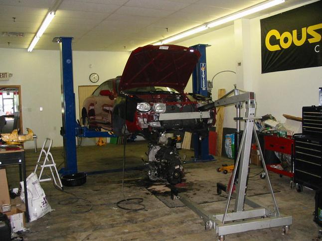
3 1. Major engine repair or overhaul will require from the vehicle, while some relatively major engine repairs on the upper end can be made with the engine still in the vehicle. Removal Replacement Rehearsal


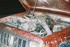
4 2. No matter what the engine point will be, a first step preceding engine removal is cleaning the engine compartment with degreaser solution that emulsifies into a hot soapy solution with hot water. Entry Exit Lift

5
6

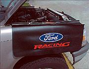
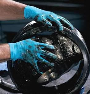
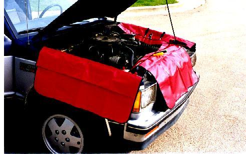
7 3. Protecting yourself with gloves and the vehicle with covers and disposable floor mats will result in more successful major engine work. Seat Roof Fender

8


9 4. Proceed by removing the, making electrical & fuel system, dealing with accessories like PS & AC, draining the engine, and disconnecting the exhaust system. Hood, Disconnects, Coolant


10 5. Drive line components like FWD shafts and RWD transmissions will have to be dealt with. Half Quarter Full


11 6. The torque converter must remain with the as the engine is removed. Depending on arrangement, transmission can stay in the car, be removed before engine, or be removed with engine. Engine Transmission Clutch


12 7. If bolting a to an engine, threads must go into the block a minimum of 1 ½ times their O.D. Sling Bling Chain

13 Engine Support Fixture
14

15


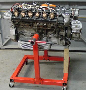
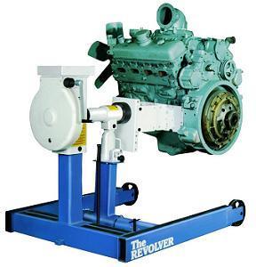
16 8. Once removed from the vehicle, the engine should be mounted on a as soon as possible. Stand Floor Bench
17


18 9. To assist with failure, cylinder heads as well as all wear mated parts should be marked, labeled & kept organized. Diagnosing Predicting Guessing


19 10. When loosening valve train components, valves may bend on engines that slam the valves into the pistons if they are out of time. That is not an issue with freewheeling engines. Interference Interruption Interrogative
20


21

22 11. Cylinder head bolts should be loosened or turns working from the of the head toward the center to prevent distortion. (Keep the head gaskets to compare with the new ones.) 1 or 2 3 or 4 5 or 6 Center Ends Middle


23 If either the camshaft or the lifters are damaged or worn, both should be Replaced since they are wear mated.


24 Removal of camshaft bearing caps on OHC engines must be done in steps sequentially to prevent distortion and breakage of the camshaft itself or the cam tower assembly.


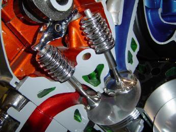
25 A valve spring compressor is needed to remove the keepers from the valves. Keep all valve train parts in order for inspection and possible reuse. They too are wear mated.


26 Valve stems with peened or mushroomed tips must often be filed to get them out of the guide.

27


28 Valves that cannot be refaced without leaving 1/32 minimum margin must be replaced.


29 Timing components like sprockets, chains, belts & tensioners should be replaced during overhaul. They are often available as a service kit.


30 A ring ridge reamer is used to remove the cylinder ring ridge before pistons can be removed.


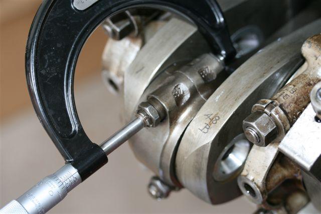
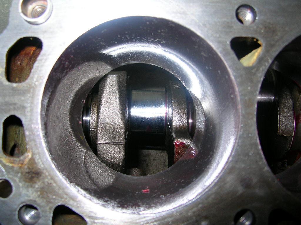
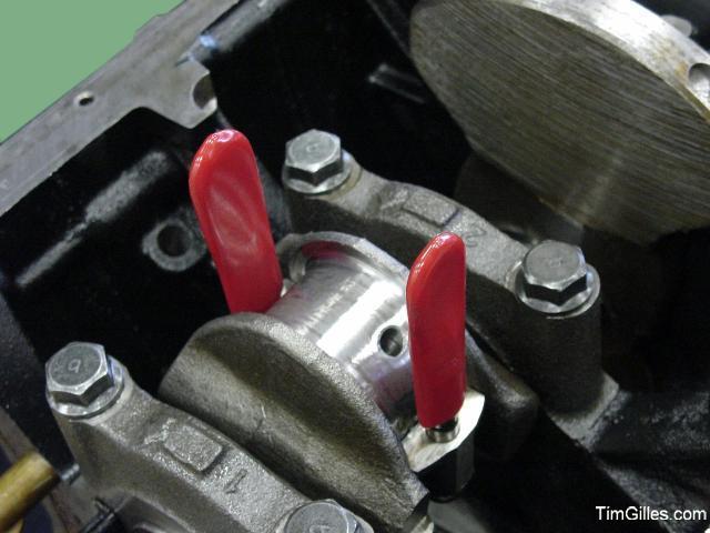
31 Use a center punch or number stamps to identify every connecting rod & cap and every main bearing cap before removal. Stamp them on the external flat surfaces.


32 Rod bolts should be covered with protectors to prevent crankshaft rod journal damage during removal.


33
34

35 Mark the flywheel/flex plate to maintain balance during reassembly.


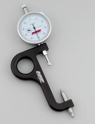
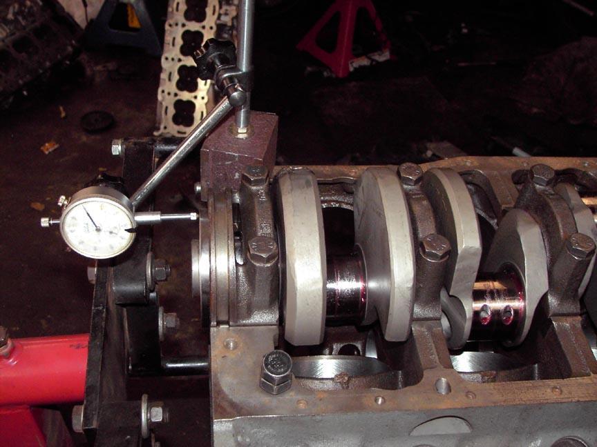
36 It is wise to plastigage bearings at disassembly to determine wear, as well as during reassembly to determine new bearing clearance.

")


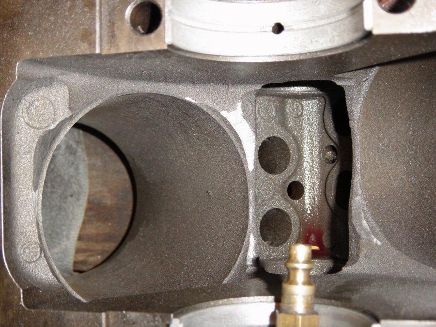
37 Remove all core plugs (freeze plugs) & oil gallery plugs prior to block cleaning.


38 For decisions on machining & parts ordering, measurements must be taken.


39 12. Cleaning methods depend upon the component to be cleaned and the of which it is made. Incorrect cleaning methods or agents could be more harmful than no cleaning at all! Year Material Country
 soils like petroleum by products")
 mineral deposits/scale.")
40 13. Contaminants fall into 4 categories: 1) soils, 2) soils like petroleum by products combustion byproducts, & coatings, 3) rust, & 4) mineral deposits/scale. Water Soluble, Organic Soils


41 14. The 3 basic processes for cleaning automotive parts are: 1) cleaning, 2), and 3) cleaning. Chemical, Thermal, Abrasive


42 15. Parts washers, soak tanks, and hot spray tanks are examples of cleaning. Chemical Thermal Abrasive


43 16. cleaning ovens operate between F to oxidize greases & oils into ash. Chemical Thermal Abrasive


44 17. Shot, tumbling, vibratory cleaning, and scraping with power tools are examples of the abrasive cleaning processes. Note: Shot Peening is different than Shot Blasting Blasting
45 18. Once parts are thoroughly cleaned, crack and repair can be done. Before repairing damaged engine parts, it is advisable to determine the cause of the fatigue & failure. Detection or Inspection
 checks on a cylinder block or")
")

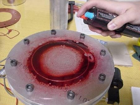
46 19. Common methods of crack detection are: 1) checks on a cylinder block or head, 2) (MPI) done to cast iron parts, also known as magnafluxing, and 3) penetrant, that can be done on iron as well as aluminum. Pressure Magnetic Particle Inspection Dye

47
48


49

50

51


52 Magnaflux method is applied for crack detection during crankshaft testing. The crank is previously soaked with a liquid which is sensitive to magnetism and ultraviolet light. The grinding process starts after each part has been measured very meticulously.
53
54
55
Advanced Auto Tech. ASE A 1 Test Preparation Engine Upper End Theory & Service
 Advanced Auto Tech ASE A 1 Test Preparation Engine Upper End Theory & Service Torque to yield bolts stretch to their yield point when tightened and should not be reused. True or False The sealing lip &
AUTOMOTIVE TECHNOLOGY 41 COURSE SYLLABUS
 AUTOMOTIVE TECHNOLOGY 41 COURSE SYLLABUS Course Description: Recommended: AT1 or pass the Auto Tech 1 Placement Test. Principles of engine rebuilding, includes diagnosis, removing, disassembly, cleaning,
1.8L & 2.2L 4-CYL Article Text 1998 Subaru Impreza
 1.8L & 2.2L 4-CYL Article Text 1998 Subaru Impreza ARTICLE BEGINNING 1995-98 ENGINES Subaru - 1.8L & 2.2L 4-Cylinder 1995-97: Impreza (1.8L) 1995-98: Impreza (2.2L), Legacy (2.2L) * PLEASE READ THIS FIRST
Valve Timing Inspection and Adjustment
 Document ID: 2094866 http://localhost:9001/si/showdoc.do?docsyskey=2094866&pubcellsyskey=123728&pubo... Page 1 of 3 2009 Chevrolet Aveo Aveo, Wave, G3, Barina (VIN S/T) Service Manual Engine Engine Mechanical
ENGINE OVERHAUL PROCEDURES - GENERAL INFORMATION
 ENGINE OVERHAUL PROCEDURES - GENERAL INFORMATION 1994 Toyota Celica Engine Overhaul Procedures - General Information ALL PISTON ENGINES * PLEASE READ THIS FIRST * Examples used in this article are general
ENGINE OVERHAUL PROCEDURES - GENERAL INFORMATION
 ENGINE OVERHAUL PROCEDURES - GENERAL INFORMATION 1992 Subaru SVX Engine Overhaul Procedures - General Information ALL PISTON ENGINES * PLEASE READ THIS FIRST * Examples used in this article are general
1998 Saab 900 SE ENGINES Saab 2.0L & 2.3L 4-Cylinder
 Removal & Installation See VALVE SPRINGS under CYLINDER HEAD under OVERHAUL. CAMSHAFT Removal 1. Rotate crankshaft until "0" mark on flywheel aligns with timing mark on flywheel cover. Remove inspection
CRANKSHAFT & MAIN BEARINGS
 CRANKSHAFT & MAIN BEARINGS * PLEASE READ THIS FIRST * REMOVAL Ensure all main bearing caps are marked for location on cylinder block. Some main bearing caps have an arrow stamped on them. The arrow must
EM 128 2UZ-FE ENGINE MECHANICAL ENGINE UNIT INSPECTION
 128 2UZ-FE ENGINE MECHANICAL ENGINE UNIT INSPECTION HINT: Thoroughly clean all parts to be assembled. Before installing the parts, apply new engine oil to all sliding and rotating surfaces. Replace all
ARTICLE BEGINNING * PLEASE READ THIS FIRST * ENGINE IDENTIFICATION INSPECTION PROCEDURES * PLEASE READ THIS FIRST * GENERAL
 Article Text ARTICLE BEGINNING Engine Overhaul Procedures - General Information ALL PISTON ENGINES * PLEASE READ THIS FIRST * Examples used in this article are general in nature and do not necessarily
Advanced Auto Tech. ASE A 1 Test Preparation Engine Lower End Theory & Service
 Advanced Auto Tech ASE A 1 Test Preparation Engine Lower End Theory & Service To make work easier, one of the first steps often done before engine removal is to clean & degrease the engine compartment.
REMOVAL & INSTALLATION
 REMOVAL & INSTALLATION TIMING BELT Removal (Esteem) 1. Disconnect negative battery cable. Remove right side engine under cover. Remove power steering and A/C compressor drive belts. 2. Remove A/C compressor
11.Preparation for Overhaul
 11.Preparation for Overhaul A: PROCEDURE 1) After removing the engine from body, secure it in the ST shown below. ST1 498457000 ENGINE STAND ADAPTER RH ST2 498457100 ENGINE STAND ADAPTER LH ST3 499817000
INSPECTION. (b) Clean the combustion chambers. Using a wire brush, remove all the carbon from the combustion NOTICE:
 Clean the combustion chambers. Using a wire brush, remove all the carbon from the combustion NOTICE:") ENGINE MECHANICAL (2JZGE) INSPECTION EM41 EM0DC05 1. CLEAN TOP SURFACES OF PISTONS AND CYL- INDER BLOCK (a) Turn the crankshaft, and bring each piston to top dead center (TDC). Using a gasket scraper,
ENGINE MECHANICAL (2JZGE) INSPECTION EM41 EM0DC05 1. CLEAN TOP SURFACES OF PISTONS AND CYL- INDER BLOCK (a) Turn the crankshaft, and bring each piston to top dead center (TDC). Using a gasket scraper,
ENGINE MECHANICAL (M13 ENGINE) 6A1-51
 6A1-51") ENGINE MECHANICAL (M13 ENGINE) 6A1-51 Check cylinder head for cracks on intake and exhaust ports, combustion chambers, and head surface. Using a straightedge and thickness gauge, check flatness of gasketed
ENGINE MECHANICAL (M13 ENGINE) 6A1-51 Check cylinder head for cracks on intake and exhaust ports, combustion chambers, and head surface. Using a straightedge and thickness gauge, check flatness of gasketed
7. CYLINDER HEAD/VALVES
 7 7 7-0 SERVICE INFORMATION...7-1 CYLINDER HEAD DISASSEMBLY...7-7 TROUBLESHOOTING...7-2 CYLINDER HEAD ASSEMBLY...7-8 CAMSHAFT REMOVAL...7-3 CYLINDER HEAD INSTALLATION...7-8 CYLINDER HEAD REMOVAL...7-5
Fig. 6: Assembling Piston & Rod. NOTE: Notch must face forward Toyota Starlet CRANKSHAFT MAIN BEARINGS
 connecting rods are marked for reassembly. 3. Thoroughly clean and inspect all components. Coat pin with engine oil and heat piston to 158-176 F (70-80 C). Pin should push fit with thumb pressure through
1.6L 4-CYL - VIN [E]
![1.6L 4-CYL - VIN [E]](/thumbs/81/84172348.jpg "1.6L 4-CYL - VIN [E]") 1.6L 4-CYL - VIN [E] 1993 Nissan Sentra 1993 NISSAN ENGINES 1.6L 4-Cylinder NX, Sentra * PLEASE READ THIS FIRST * NOTE: For engine repair procedures not covered in this article, see ENGINE OVERHAUL PROCEDURES
1.6L 4-CYL - VIN [E] 1993 Nissan Sentra 1993 NISSAN ENGINES 1.6L 4-Cylinder NX, Sentra * PLEASE READ THIS FIRST * NOTE: For engine repair procedures not covered in this article, see ENGINE OVERHAUL PROCEDURES
ENGINE MEASUREMENTS ENGINE MEASUREMENTS AND SPECIFICATIONS CYLINDER HEAD. Measure Cylinder Compression. Using Telescoping Gauges and Hole Gauges
 ENGINE MEASUREMENTS AND SPECIFICATIONS Tool List Qty. Required Compression Gauge, 20 kgf/cm²: E-Z-GO Part No. N/A... 1 Compression Gauge Adapter, M14 1.25: E-Z-GO Part No. N/A... 1 Valve Seat Cutter, 45-35
INSPECTION. (b) Using a wire brush, remove all the carbon from the combustion NOTICE:
 Using a wire brush, remove all the carbon from the combustion NOTICE:") EM44 ENGINE MECHANICAL (2RZFE, 3RZFE) INSPECTION EM16R02 1. CLEAN TOP SURFACES OF PISTONS AND CYL- INDER BLOCK (a) Turn the crankshaft, and bring each piston to top dead center (TDC). (b) Using a gasket
EM44 ENGINE MECHANICAL (2RZFE, 3RZFE) INSPECTION EM16R02 1. CLEAN TOP SURFACES OF PISTONS AND CYL- INDER BLOCK (a) Turn the crankshaft, and bring each piston to top dead center (TDC). (b) Using a gasket
INSPECTION. (b) Using a wire brush, remove all the carbon from the combustion NOTICE:
 Using a wire brush, remove all the carbon from the combustion NOTICE:") EM38 ENGINE MECHANICAL (5VZFE) INSPECTION EM16E02 1. CLEAN TOP SURFACES OF PISTONS AND CYL- INDER BLOCK (a) Turn the crankshaft and bring each piston to top dead center (TDC). (b) Using a gasket scraper,
EM38 ENGINE MECHANICAL (5VZFE) INSPECTION EM16E02 1. CLEAN TOP SURFACES OF PISTONS AND CYL- INDER BLOCK (a) Turn the crankshaft and bring each piston to top dead center (TDC). (b) Using a gasket scraper,
CYLINDER HEAD OVERHAUL
 ENGINE OVERHAUL PROCEDURES - GENERAL INFORMATION -2011 Mercedes-... Page 1 of 20 CYLINDER HEAD OVERHAUL * PLEASE READ THIS FIRST * Examples used in this article are general in nature and do not necessarily
2.4L 4-CYL - VINS [F,H,S]
![2.4L 4-CYL - VINS [F,H,S]](/thumbs/72/66412829.jpg "2.4L 4-CYL - VINS [F,H,S]") 2.4L 4-CYL - VINS [F,H,S] 1990 Nissan 240SX 1990 ENGINES Nissan 2.4L 4-Cylinder Axxess, Pickup, Stanza, 240SX * PLEASE READ THIS FIRST * NOTE: For engine repair procedures not covered in this article,
2.4L 4-CYL - VINS [F,H,S] 1990 Nissan 240SX 1990 ENGINES Nissan 2.4L 4-Cylinder Axxess, Pickup, Stanza, 240SX * PLEASE READ THIS FIRST * NOTE: For engine repair procedures not covered in this article,
OVERHAUL. 1. REMOVE W/HEAD TAPER SCREW PLUG NO.2 (a) Using a socket hexagon wench 10, remove the taper screw plug and gasket.
 Using a socket hexagon wench 10, remove the taper screw plug and gasket.") 14138 ENGINE MECHANICAL OVERHAUL 140Q703 1. REMOVE W/HEAD TAPER SCREW PLUG NO.2 (a) Using a socket hexagon wench 10, remove the taper screw plug and gasket. A62890 2. REMOVE VALVE LIFTER (a) Remove the
14138 ENGINE MECHANICAL OVERHAUL 140Q703 1. REMOVE W/HEAD TAPER SCREW PLUG NO.2 (a) Using a socket hexagon wench 10, remove the taper screw plug and gasket. A62890 2. REMOVE VALVE LIFTER (a) Remove the
1999 Acura SLX. Fig. 6: Identifying Piston & Connecting Rod Size Courtesy of ISUZU MOTOR CO.
 3. Check cylinder bore to determine piston-to-cylinder clearance. Clearance should be within specification. See PISTONS, PIN & RINGS table under ENGINE SPECIFICATIONS. Fig. 6: Identifying Piston & Connecting
CRANKSHAFT. Preceding Works: Removal of end cover Removal of pistons Removal of crankshaft sprocket
 30 02 CRANKSHAFT Preceding Works: Removal of end cover Removal of pistons Removal of crankshaft sprocket 1. Crankshaft main bearing shells, upper 2. Upper thrust bearing 3. Crankshaft 4. Crankshaft main
Valvetrain, servicing
 Page 1 of 51 15-32 Valvetrain, servicing Note: Cylinder heads with small cracks between the valve seats that are less than 0.3 mm (0.012 in.) wide and/or between one valve seat and only the first 4 threads
1991 Nissan 240SX. 2.4L 4-CYL - VINS [F,M,S] 1991 ENGINES Nissan 2.4L 4-Cylinder
![1991 Nissan 240SX. 2.4L 4-CYL - VINS [F,M,S] 1991 ENGINES Nissan 2.4L 4-Cylinder](/thumbs/95/123571962.jpg "1991 Nissan 240SX. 2.4L 4-CYL - VINS [F,M,S] 1991 ENGINES Nissan 2.4L 4-Cylinder") NOTE: Use illustration for component reference. See Fig. 7. 1. Remove spark plug wires. Set No. 1 piston at TDC on its compression stroke. Remove vacuum hoses, electrical harnesses, connectors, and harness
NOTE: Use illustration for component reference. See Fig. 7. 1. Remove spark plug wires. Set No. 1 piston at TDC on its compression stroke. Remove vacuum hoses, electrical harnesses, connectors, and harness
EM 84 ENGINE MECHANICAL (2RZ FE, 3RZ FE) EM16Y 02 DISASSEMBLY
 EM16Y 02 DISASSEMBLY") EM84 ENGINE MECHANICAL (2RZFE, 3RZFE) EM16Y02 DISASSEMBLY 1. M/T: REMOVE FLYWHEEL Remove the 10 bolts and flywheel. 2. A/T: REMOVE DRIVE PLATE Remove the 10 bolts, front spacer, drive plate and rear plate.
EM84 ENGINE MECHANICAL (2RZFE, 3RZFE) EM16Y02 DISASSEMBLY 1. M/T: REMOVE FLYWHEEL Remove the 10 bolts and flywheel. 2. A/T: REMOVE DRIVE PLATE Remove the 10 bolts, front spacer, drive plate and rear plate.
CO/HC INSPECTION HINT:
 CO/HC CO/HC INSPECTION EM1 EM0KQ07 This check is used only to determine whether or not the idle CO/ HC complies with regulations. 1. INITIAL CONDITIONS (a) The engine is at normal operating temperature.
9-8 LEFT CRANKCASE COVER INSTALLATION ALTERNATORETARTER A TORIST ARTER CLUTCH. Install the dowel pin and a new gasket.
 ALTERNATORETARTER A TORIST ARTER CLUTCH LEFT CRANKCASE COVER INSTALLATION Install the dowel pin and a new gasket. Install the left crankcase cover. Install the washer and bolts, and tighten them securely.
20.Cylinder Block. Cylinder Block A: REMOVAL ME(H4DOTC)-63 ST CRANKSHAFT STOPPER
-63 ST CRANKSHAFT STOPPER") Cylinder Block MECHANICAL 20.Cylinder Block A: REMOVAL Before conducting this procedure, drain engine oil completely. 1) Remove the intake manifold. 2)
Cylinder Block MECHANICAL 20.Cylinder Block A: REMOVAL Before conducting this procedure, drain engine oil completely. 1) Remove the intake manifold. 2)
Engine Mechanical Engine Block
 Engine Mechanical Engine lock Special Tools... 7-2 Component Location Index... 7-3 Connecting Rod and Crankshaft End Play Inspection... 7-6 Crankshaft Main earing Replacement... 7-7 Connecting Rod earing
CLEANING, INSPECTION AND REPAIR. Valve Spring Compressor (Part No. HD-34736B) Figure Compressing Valve Springs
 Figure Compressing Valve Springs") b0134x3x 5694 8 7 12 10 1 6 13 11 Valve Spring Compressor (Part No. HD-34736B) 9 Figure 3-11. Compressing Valve Springs 5 14 4 3 2 15 2767a 1. Right crankcase half 2. Pin (2) 3. O-ring (2) 4. Plate 5.
b0134x3x 5694 8 7 12 10 1 6 13 11 Valve Spring Compressor (Part No. HD-34736B) 9 Figure 3-11. Compressing Valve Springs 5 14 4 3 2 15 2767a 1. Right crankcase half 2. Pin (2) 3. O-ring (2) 4. Plate 5.
CO/HC INSPECTION HINT:
 ENGINE MECHANICAL (2UZFE) CO/HC CO/HC INSPECTION HINT: EM1 EM0KQ09 This check is used only to determine whether or not the idle CO/ HC complies with regulations. 1. INITIAL CONDITIONS (a) Engine at normal
 Page 1 of 21 303-01C Engine 5.4L (3V) 2009 F-150 REMOVAL Procedure revision date: 03/26/2009 Cylinder Head Special Tool(s) 3 Jaw Puller 303-D121 or equivalent Compressor, Valve Spring 303-1039 Holding
2005 Hyundai Tucson LX. On some models, engine is equipped with a timing belt and timing chain. Inspect timing chain when replacing timing belt.
 TIMING BELT NOTE: On some models, engine is equipped with a timing belt and timing chain. Inspect timing chain when replacing timing belt. Removal 1. Remove the engine cover. See Fig. 1. 2. Remove right
2010 Transit Connect Workshop Manual. 31. Remove the 3 bolts, thermostat housing and thermostat.
 31. Remove the 3 bolts, thermostat housing and thermostat. 32. Remove the 2 bolts, stud bolt and the A/C compressor. 33. Remove the bolt and the KS. 34. Remove the 8 bolts and the crankcase vent oil separator.
2.0L 4-CYL & 2.0L 4-CYL TURBO - VIN [S]
![2.0L 4-CYL & 2.0L 4-CYL TURBO - VIN [S]](/thumbs/81/82864711.jpg "2.0L 4-CYL & 2.0L 4-CYL TURBO - VIN [S]") 2.0L 4-CYL & 2.0L 4-CYL TURBO - VIN [S] 1988 Toyota Celica 1988 TOYOTA ENGINES 2.0L & 2.0L Turbo 4-Cylinder Celica * PLEASE READ THIS FIRST * NOTE: For engine repair procedures not covered in this article,
2.0L 4-CYL & 2.0L 4-CYL TURBO - VIN [S] 1988 Toyota Celica 1988 TOYOTA ENGINES 2.0L & 2.0L Turbo 4-Cylinder Celica * PLEASE READ THIS FIRST * NOTE: For engine repair procedures not covered in this article,
 DRUM BRAKE RIMS Periodic inspection of drum brake rims is necessary to determine indications of uneven or excessive wear. In general, brake rim failures other that regular wear are caused by brake linings
MACHINE SHOP LABOUR GUIDE
 MACHINE SHOP LABOUR GUIDE MACHINE SHOP LABOUR GUIDE 2 Track Record Quality Environmental Policy Statement Lordco has a proven track record you can trust. We are one of the largest and most modern Automotive
OVERHAULING THE ENGINE. 85 Nm (8.5 m kg, 61 ft Ib) Order Job/Part Q ty Remarks Removing the drive sprocket
 Order Job/Part Q ty Remarks Removing the drive sprocket") INE EAS00188 INE DRIVE SPROCKET OVERHAULING THE INE 10 Nm (1.0 m kg, 7.2 ft Ib) 85 Nm (8.5 m kg, 61 ft Ib) Order Job/Part Q ty Remarks Removing the drive sprocket Remove the parts in the order listed.
INE EAS00188 INE DRIVE SPROCKET OVERHAULING THE INE 10 Nm (1.0 m kg, 7.2 ft Ib) 85 Nm (8.5 m kg, 61 ft Ib) Order Job/Part Q ty Remarks Removing the drive sprocket Remove the parts in the order listed.
VALVE CLEARANCE (K3-VE)
") ENGINE MECHANICAL VALVE CLEARANCE (K3-VE) 25 ENGINE MECHANICAL VALVE CLEARANCE (K3-VE) INSPECTION 1. DISCONNECT NEGATIVE BATTERY TERMINAL (See page RS-164.) 2. ROVE ENGINE UNDER COVER 3. DRAIN ENGINE COOLANT
ENGINE MECHANICAL VALVE CLEARANCE (K3-VE) 25 ENGINE MECHANICAL VALVE CLEARANCE (K3-VE) INSPECTION 1. DISCONNECT NEGATIVE BATTERY TERMINAL (See page RS-164.) 2. ROVE ENGINE UNDER COVER 3. DRAIN ENGINE COOLANT
Machine Shop Labour Guide
 Machine Shop Labour Guide Langley Machine Shop 20121 Industrial Avenue, Unit 101 Langley, BC V3A 4K6 Phone: 604-530-3943 Contact: Ron Croteau Email: lordco11@lordco.com Mission Head Shop 32885 London Avenue
CYLINDER HEAD ASSY (1MZ FE)
") OVERHAUL 1. REMOVE W/HEAD STRAIGHT SCREW PLUG NO.1 14209 1405K01 Using a 14 mm straight hexagon wrench, remove the screw plug. 2. REMOVE W/HEAD STRAIGHT SCREW PLUG NO.2 Using a 14 mm straight hexagon wrench,
OVERHAUL 1. REMOVE W/HEAD STRAIGHT SCREW PLUG NO.1 14209 1405K01 Using a 14 mm straight hexagon wrench, remove the screw plug. 2. REMOVE W/HEAD STRAIGHT SCREW PLUG NO.2 Using a 14 mm straight hexagon wrench,
TIMING BELT TIMING BELT
 TIMING BELT TIMING BELT DISASSEMBLY 1. Lift the vehicle by using of jack. 2. Remove the engine support bracket. (14 mm bolt and 2 nuts, 17 mm bolt) 3. Remove the power steering belt. 4. Remove the air
INSPECTION. (b) Using a wire brush, remove all the carbon from the combustion NOTICE:
 Using a wire brush, remove all the carbon from the combustion NOTICE:") EM44 INSPECTION EM11E01 1. CLEAN TO P SURFACES O F PI STO NS AND CYL- INDER BLOCK (a) Turn the crankshaft, and bring each piston to top dead center (TDC). Using a gasket scraper, remove all the carbon
EM44 INSPECTION EM11E01 1. CLEAN TO P SURFACES O F PI STO NS AND CYL- INDER BLOCK (a) Turn the crankshaft, and bring each piston to top dead center (TDC). Using a gasket scraper, remove all the carbon
Refer to procedure. Note: Engine; Tightening torque. Service and Repair; Disassembly and Assembly. 25 Nm. Note: Engine.
 Engine Cylinder head Refer to procedure Note: Engine; Service and Repair; Disassembly and Assembly Refer to procedure Note: Engine; Service and Repair; Disassembly and Assembly Head bolt reuse/replace
2.2L 4-CYL & 2.3L 4-CYL
 2.2L 4-CYL & 2.3L 4-CYL Article Text 1993 Honda Prelude For Cadi Centre Nsk CA 95051 Copyright 1998 Mitchell Repair Information Company, LLC Sunday, July 08, 2001 11:17AM ARTICLE BEGINNING 1993 HONDA ENGINES
CRANKSHAFT/TRANSMISSION 9-9
 Crankcase Splitting CRANKSHAFT/TRANSMISSION 9-9 Crankcase Splitting Remove the engine (see Engine Removal in the Engine Removal/Installation chapter). Set the engine on a clean surface and hold the engine
Disassembly and Assembly
 SENR9973-01 September 2007 Disassembly and Assembly 400C Industrial Engine HB (Engine) HD (Engine) HH (Engine) HL (Engine) HM (Engine) HN (Engine) HP (Engine) HR (Engine) Important Safety Information Most
MULTIPLE CHOICE. Choose the one alternative that best completes the statement or answers the question.
 Exam Name MULTIPLE CHOICE. Choose the one alternative that best completes the statement or answers the question. 1) When preparing for a compression test, technician A disables the ignition system. Technician
2.2L 4-CYL - VIN [S]
![2.2L 4-CYL - VIN [S]](/thumbs/72/67564355.jpg "2.2L 4-CYL - VIN [S]") 2.2L 4-CYL - VIN [S] 1994 Toyota Celica 1994 ENGINES Toyota 2.2L 4-Cylinder Celica NOTE: For repair procedures not covered in this article, see ENGINE OVERHAUL PROCEDURES - GENERAL INFORMATION article
2.2L 4-CYL - VIN [S] 1994 Toyota Celica 1994 ENGINES Toyota 2.2L 4-Cylinder Celica NOTE: For repair procedures not covered in this article, see ENGINE OVERHAUL PROCEDURES - GENERAL INFORMATION article
(a) Short-term storage of tubeless wheel assemblies may be stored with the wheel o- ring packing installed between the two halves.
 Short-term storage of tubeless wheel assemblies may be stored with the wheel o- ring packing installed between the two halves.") Manual AWBCMM0001-7.2/USA Section 300 External Design (2) Wheels Stored Without Tires Installed (a) Short-term storage of tubeless wheel assemblies may be stored with the wheel o- ring packing installed
Manual AWBCMM0001-7.2/USA Section 300 External Design (2) Wheels Stored Without Tires Installed (a) Short-term storage of tubeless wheel assemblies may be stored with the wheel o- ring packing installed
ENGINE MECHANICAL PREPARATION SST mm Socket Wrench for 12 Pointed Head
 SST 027 023HH01 0901138121 12 mm Socket Wrench for 12 Pointed Head CYLINDER BLOCK ASSY(2AZFE) PARTIAL ENGINE ASSY(3MZFE) (3MZFE) NO.2(3MZFE) CYLINDER BLOCK ASSY(3MZFE) 0903200100 Oil Pan Seal Cutter PARTIAL
5.7L V Chevrolet Camaro * PLEASE READ THIS FIRST * ENGINE IDENTIFICATION VEHICLE IDENTIFICATION NUMBER (VIN) ADJUSTMENTS
 ADJUSTMENTS") 5.7L V8 2001 Chevrolet Camaro 2000-01 ENGINES General Motors 5.7L V8 Chevrolet; Camaro Pontiac; Firebird * PLEASE READ THIS FIRST * NOTE: For engine repair procedures not covered in this article, see ENGINE
5.7L V8 2001 Chevrolet Camaro 2000-01 ENGINES General Motors 5.7L V8 Chevrolet; Camaro Pontiac; Firebird * PLEASE READ THIS FIRST * NOTE: For engine repair procedures not covered in this article, see ENGINE
OVERHAUL. 1. REMOVE VALVE LIFTER HINT: Arrange the valve lifter in the correct order.
 ENGINE MECHNICL 1473 OVERHUL 1415F02 1. REMOVE VLVE LIFTER HINT: rrange the valve lifter in the correct order. 75601 SST Wooden Block 75602 2. REMOVE VLVE HINT: rrange the valves, inner compression springs,
SPECIFICATIONS TEST AND ADJUSTMENT SPECIFICATIONS SPECIFICATIONS ENGINE FD620D, K SERIES
 ENGINE FD620D, K SERIES SPECIFICATIONS SPECIFICATIONS TEST AND ADJUSTMENT SPECIFICATIONS Engine Oil Pressure Sensor Activates............................... 98 kpa (14.2 psi) Oil Pressure While Cranking
ENGINE MECHANICAL (G13B, 1-CAM 16-VALVES ENGINE)
") ENGINE MECHANICAL (G13B, 1-CAM 16-VALVES ENGINE) 6A1-1 SECTION 6A1 ENGINE MECHANICAL (G13B, 1-CAM 16-VALVES ENGINE) WARNING: For vehicles equipped with Supplement Restraint (Air Bag) System: Service on
ENGINE MECHANICAL (G13B, 1-CAM 16-VALVES ENGINE) 6A1-1 SECTION 6A1 ENGINE MECHANICAL (G13B, 1-CAM 16-VALVES ENGINE) WARNING: For vehicles equipped with Supplement Restraint (Air Bag) System: Service on
AUTOMOTIVE TECHNOLOGY SYLLABUS (rev. Fall 2012)
") AUTOMOTIVE TECHNOLOGY SYLLABUS (rev. Fall 2012) AUMT 1319: AUTOMOTIVE ENGINE REPAIR SEMESTER HOURS: 3 TEXTBOOK Chek-Chart: Automotive Engine Repair And Rebuilding COURSE DESCRIPTION; Fundamentals of engine
AUTOMOTIVE TECHNOLOGY SYLLABUS (rev. Fall 2012) AUMT 1319: AUTOMOTIVE ENGINE REPAIR SEMESTER HOURS: 3 TEXTBOOK Chek-Chart: Automotive Engine Repair And Rebuilding COURSE DESCRIPTION; Fundamentals of engine
CYLINDER HEAD. Cylinder Head Assembly. Sized for Print VALVES
 CYLINDER HEAD Cylinder Head Assembly VALVES DISASSEMBLY 1. Using a tool remove the cylinder head bolts in the order shown in the illustration. 2. Using the special tool (09222-28000, 09222-28100), remove
Disassembly and Assembly
 K EN R 623 2-00 August 2006 Disassembly and Assembly 2506-15 Industrial Engine M G A (Engine) MGB (Engine) M G D (Engine) Important Safety Information Most accidents that involve product operation, maintenance
ENGINE MECHANICAL EM SECTION CONTENTS
 ENGINE MECHANICAL EM SECTION CONTENTS INTAKE MANIFOLD...EM-2 Component Parts Location...EM-2 Removal and Installation...EM-3 Inspection...EM-3 EXHAUST MANIFOLD...EM-4 Component Parts Location...EM-4 Removal
15.Timing Belt. Timing Belt A: REMOVAL ME(STI) TIMING BELT
 TIMING BELT") 15.Timing Belt A: REMOVAL NOTE: Perform the work with the engine installed to body when replacing a single part. For operation procedures, refer to Timing Belt in the PM section.
15.Timing Belt A: REMOVAL NOTE: Perform the work with the engine installed to body when replacing a single part. For operation procedures, refer to Timing Belt in the PM section.
Service and Repair CAMSHAFT
 Service and Repair CAMSHAFT Removal and Installation REMOVAL 1. Remove front timing chain case, camshaft sprocket, timing chain and rear timing chain case. Refer to "REMOVAL". 2. Remove camshaft position
2001 Chevrolet Metro LSi ENGINES 1.3L 4-Cylinder - Metro & Firefly (Canadian) Fig. 3: Exploded View Of Timing Belt & Components (Typical)
 Fig. 3: Exploded View Of Timing Belt & Components (Typical)") Fig. 3: Exploded View Of Timing Belt & Components (Typical) Fig. 4: Aligning Timing Marks 6. Loosen the timing belt tensioner bolt and the stud. 7. After pushing up the tensioner plate completely with
Fig. 3: Exploded View Of Timing Belt & Components (Typical) Fig. 4: Aligning Timing Marks 6. Loosen the timing belt tensioner bolt and the stud. 7. After pushing up the tensioner plate completely with
19.Cylinder Head. Cylinder Head
 19. A: REMOVAL 1) Remove the V-belts. 2) Remove the crank pulley. 3) Remove the timing belt cover.
15.Timing Chain Assembly
 15. A: REMOVAL 1. TIMING CHAIN RH When replacing a single part, perform the work with the engine assembly installed to body. 1) Remove the chain cover. 2) Using
ENG V-BELT AUTOMATIC TRANSMISSION Tighten: primary sheave nut 1
 V-BELT AUTOMATIC TRANSMISSION 2 1 5. Tighten: primary sheave nut 1 Nm (16.0 m kg, 115 ft lb) T R.. 160 CAUTION: Before tightening the nut to remount the primary sheave, make sure that the serrations of
Piston and Connecting Rod Assembly January Removal of the Piston and Connecting Rod Assembly
 1 18-13 1 1 18-13 SUBJECT DATE Piston and Connecting Rod Assembly January 2013 Additions, Revisions, or Updates Publication Number / Title Platform Section Title Change Removal of the Piston and Connecting
Valve gear, servicing
 Page 1 of 62 15-1 Valve gear, servicing WARNING! Do not re-use any fasteners that are worn or deformed in normal use. Some fasteners are designed to be used only once, and are unreliable and may fail if
26/01/2017 3GR-FSE ENGINE MECHANICAL: ENGINE UNIT: DISASSEMBLY; 2006 MY GS300 [01/ ]
![26/01/2017 3GR-FSE ENGINE MECHANICAL: ENGINE UNIT: DISASSEMBLY; 2006 MY GS300 [01/ ]](/thumbs/85/92233007.jpg "26/01/2017 3GR-FSE ENGINE MECHANICAL: ENGINE UNIT: DISASSEMBLY; 2006 MY GS300 [01/ ]") Last Modified: 8-24-2016 6.6 A Doc ID: RM000000T4X000X Model Year Start: 2006 Model: GS300 Prod Date Range: [01/2005 - ] Title: 3GR-FSE ENGINE MECHANICAL: ENGINE UNIT: DISASSEMBLY; 2006 MY GS300 [01/2005
Last Modified: 8-24-2016 6.6 A Doc ID: RM000000T4X000X Model Year Start: 2006 Model: GS300 Prod Date Range: [01/2005 - ] Title: 3GR-FSE ENGINE MECHANICAL: ENGINE UNIT: DISASSEMBLY; 2006 MY GS300 [01/2005
2002 Honda Passport LX
 Fig. 151: Removing Piston Pin 11. Piston (10) Page 130 2005 Mitchell Repair Information Company, LLC. 12. Connecting rod (11) INSPECTION AND REPAIR Pistons Carefully clean away all the carbon adhering
Piston and Connecting Rod Assembly August Removal of the Piston and Connecting Rod Assembly
 1 8 17-13 SUBJECT DATE Piston and Connecting Rod Assembly August 2013 Additions, Revisions, or Updates Publication Number / Title Platform Section Title Change Removal of the Piston DDC-SVC-MAN-0081 DD
TROUBLE SHOOTING VIBRATORY FEEDERS Contributed by ADI Representative: George Crawford
 INTRODUCTION TROUBLE SHOOTING VIBRATORY FEEDERS Contributed by ADI Representative: George Crawford Most vibratory feeders function for long periods of time without attention, without maintenance and little
CHASSIS CONTENTS EXTERIOR PARTS 6-1 FRAME COVER 6-2 REAR FRAME COVER 6-4 FRONT WHEEL 6-6 FRONT BRAKE 6-10 HANDLEBARS 6-17 FRONT FORK 6-19
 CHASSIS CONTENTS EXTERIOR PARTS 6- FRAME COVER 6- REAR FRAME COVER 6-4 FRONT WHEEL 6-6 FRONT BRAKE 6-0 HANDLEBARS 6-7 FRONT FORK 6-9 STEERING 6-6 REAR WHEEL 6-3 REAR BRAKE 6-39 6 REAR SHOCK ABSORBER 6-43
DISASSEMBLY. Engine. Special Tool(s) Locking Tool, Camshaft Phaser Sprocket Special Tool(s)
 Locking Tool, Camshaft Phaser Sprocket Special Tool(s)") 303-01B-1 DISASSEMBLY Engine Special Tool(s) Remover, Crankshaft Rear Slinger 303-514 (T95P-6701-AH) Special Tool(s) 303-01B-1 Locking Tool, Camshaft Phaser Sprocket 303-1046 Remover, Crankshaft Rear Seal
303-01B-1 DISASSEMBLY Engine Special Tool(s) Remover, Crankshaft Rear Slinger 303-514 (T95P-6701-AH) Special Tool(s) 303-01B-1 Locking Tool, Camshaft Phaser Sprocket 303-1046 Remover, Crankshaft Rear Seal
SP01A Rail, Front Upper
 Uniform Procedures For Collision Repair UPCR SP01A Rail, Front Upper 1. Description This procedure describes the repair and complete or partial replacement of an aluminum front upper rail. Inspection and
15.Timing Belt Assembly
 MECHANICAL 15.Timing Belt Assembly A: REMOVAL 1. TIMING BELT 1) Remove the V-belt. 2) Remove the crank pulley.
2/18/2017 Cylinder Head Assembly Service and Repair, Removal and Replacement: Cylinder Head
 Cylinder Head http://repair.alldata.com/alldata/article/display.action?componentid=65&itypeid=401&nonstandardid=2762152&vehicleid=47645&miles=&printfriendl 1/17 RH Splash Shield Accessory Drive Belt, Thermostat
Transmission/Crankshaft/Crank Case
 R.Crank Case Crankshaft L.Crank Case 11-0 11. Transmission/Crankshaft/Crank Case Transmission/Crankshaft/Crank Case Service Information 11-1 Troubleshooting 11-2 Transmission 11-3 Crank Case Disassembly
WARNING: ALWAYS relieve fuel pressure before disconnecting any fuel related component. DO NOT allow fuel to contact engine or electrical components.
 4.0L V8 - VINS [K,U] Selected Block 1990 Lexus LS 400 For Lextreme Powertrain 2020 S. Hacienda Blvd. # D Hacienda Heights California 91745 Copyright 1998 Mitchell Repair Information Company, LLC Friday,
Engine Dismantle and Assemble ( )
") Engine Dismantle and Assemble (21 134 8) Special Tools 15-030A Universal flange-holding wrench 21147 21-147 Vibration damper remover 15030A 16-067 Locator for clutch disc 21-167 Wrench for cylinder head
Engine Dismantle and Assemble (21 134 8) Special Tools 15-030A Universal flange-holding wrench 21147 21-147 Vibration damper remover 15030A 16-067 Locator for clutch disc 21-167 Wrench for cylinder head
AJV8 Engine Assembly. AJV8 Engine Assembly
 AJV8 Engine Assembly Contents Cylinder Block Dowels, Plugs and Pipes 2 4 Crankshaft Bearing and Cylinder Bore Dimensions 5 9 Bearing Measuring 6 Engine Dimensions and Codes 6 7 Main Bearing Selection Chart
13. CRANKCASE/CRANKSHAFT/BALANCER/PISTON/CYLINDER
 13. CRANKCASE/CRANKSHAFT/BALANCER/PISTON/CYLINDER COMPONENT LOCATION 13-2 SERVICE INFORMATION 13-3 TROUBLESHOOTING 13-4 CRANKCASE SEPARATION 13-5 CRANKSHAFT 13-7 MAIN JOURNAL BEARING 13-9 CRANKPIN BEARING
SP06A Rail, Front Lower
 Uniform Procedures For Collision Repair SP06A Rail, Front Lower 1. Description This procedure describes the repair and complete or partial replacement of an aluminum front lower rail. Inspection and evaluation
A-PDF Split DEMO : Purchase from to remove the watermark
 5-18 FUEL AND LUBRICATION SYSTEM A-PDF Split DEMO : Purchase from www.a-pdf.com to remove the watermark Use a % size drill bit with a drill-stop to remove the pilot screw plug. Set the drill-stop 6 mm
DISASSEMBLY. 1. INSTALL ENGINE TO ENGINE STAND FOR DIS- ASSEMBLY 2. REMOVE CYLINDER HEAD (See page EM 29)
") DISASSEMBLY EM67 EM9Q0. INSTALL ENGINE TO ENGINE STAND FOR DIS- ASSEMBLY. REMOVE CYLINDER HEAD (See page EM9). REMOVE WATER BYPASS PIPE Remove the nuts, bolts, water bypass pipe and gasket.. REMOVE THERMOSTAT
DISASSEMBLY EM67 EM9Q0. INSTALL ENGINE TO ENGINE STAND FOR DIS- ASSEMBLY. REMOVE CYLINDER HEAD (See page EM9). REMOVE WATER BYPASS PIPE Remove the nuts, bolts, water bypass pipe and gasket.. REMOVE THERMOSTAT
of premature failure. Remanufactured performance can compromise the system, reduce cooling capability and cause damage to the engine.
 Hub Attached to the bearing assembly is the hub which is the connecting source of power for impeller rotation. Bearing Assembly The bearing assembly is the mechanical support for continuous rotation of
15.Timing Belt. Timing Belt A: REMOVAL ME(H4DOTC) TIMING BELT
 TIMING BELT") 15. A: REMOVAL 1. TIMING BELT 1) Remove the V-belts. 2) Remove the crank pulley. 3) Remove the timing belt cover.
15. A: REMOVAL 1. TIMING BELT 1) Remove the V-belts. 2) Remove the crank pulley. 3) Remove the timing belt cover.
MECHANICAL ME(SOHC) Page
 Page") ME(SOHC) Page 1. General Description...2 2. Compression...23 3. Idle Speed...24 4. Ignition Timing...25 5. Intake Manifold Vacuum...26 6. Engine Oil Pressure...27 7. Fuel Pressure...28 8. Valve Clearance...29
ME(SOHC) Page 1. General Description...2 2. Compression...23 3. Idle Speed...24 4. Ignition Timing...25 5. Intake Manifold Vacuum...26 6. Engine Oil Pressure...27 7. Fuel Pressure...28 8. Valve Clearance...29
Troubleshooting Power Transmission Couplings
 Troubleshooting Power Transmission Couplings Introduction Power transmission couplings are used to connect two shafts that turn in the same direction on the same centerline. There are three principle types
1989 BMW 635CSi. 3.5L 6-CYL Engine - 3.5L 6-Cylinder
 Fig. 3: Rocker Arm Assembly Courtesy of BMW OF NORTH AMERICA, INC. VALVE SPRINGS NOTE: Install springs with paint stripe (tight coil end) against head. Inspection Check spring free length. Check spring
REMOVAL & INSTALLATION
 Page 1 of 11 REMOVAL & INSTALLATION TIMING BELT Tips Click a link to view tip Tech1 Question: Timing problems P0340 Tech1 Question: 2.2 TIMING PROBLEMS - RESOLVED Removal Tips Click a link to view tip
Please read the following before installation. Points to notice about sounds
 Instruction Manual for / SCUT Cylinder Kit Thank you for purchasing one of Takegawa s products. This is a piston and cylinder kit for exclusive use in Super Head+R of Takegawa s make. You are kindly requested
SPECIFICATIONS TEST AND ADJUSTMENT SPECIFICATIONS SPECIFICATIONS ENGINE FD620D, K SERIES
 TEST AND ADJUSTMENT Engine Oil Pressure Sensor Activates............................... 98 kpa (14.2 psi) Oil Pressure While Cranking (Minimum).......................... 28 kpa (4 psi) Oil Pressure.....................................
ENGINE OVERHAUL <2.4L ENGINE>
 11B-1 GROUP 11B ENGINE OVERHAUL CONTENTS GENERAL SPECIFICATIONS 11B-2 SERVICE SPECIFICATIONS 11B-2 REWORK DIMENSIONS 11B-3 TORQUE SPECIFICATIONS 11B-4 SEALANTS 11B-7 SPECIAL TOOLS 11B-8 GENERATOR
REMOVAL & INSTALLATION
 REMOVAL & INSTALLATION TIMING BELT Removal 1. Disconnect negative battery cable. Raise and support vehicle. Remove lower engine cover. On Celica and Camry, remove right front wheel. On all models, lower
SECTION 6A ENGINE MECHANICAL (G10, 1-CAM 6-VALVES ENGINE)
") ENGINE MECHANICAL (G10, 1-CAM 6-VALVES ENGINE) 6A-1 SECTION 6A ENGINE MECHANICAL (G10, 1-CAM 6-VALVES ENGINE) WARNING: For vehicles equipped with Supplemental Restraint (Air Bag) System: Service on and
ENGINE MECHANICAL (G10, 1-CAM 6-VALVES ENGINE) 6A-1 SECTION 6A ENGINE MECHANICAL (G10, 1-CAM 6-VALVES ENGINE) WARNING: For vehicles equipped with Supplemental Restraint (Air Bag) System: Service on and
5. Cylinder Block. 2-3b [W5A1] SERVICE PROCEDURE A: REMOVAL 1. RELATED PARTS
![5. Cylinder Block. 2-3b [W5A1] SERVICE PROCEDURE A: REMOVAL 1. RELATED PARTS](/thumbs/82/85637729.jpg "5. Cylinder Block. 2-3b [W5A1] SERVICE PROCEDURE A: REMOVAL 1. RELATED PARTS") 2-3b [W5A1] SERVICE PROCEDURE A: REMOVAL 1. RELATED PARTS 1) Remove timing belt, camshaft sprockets and related parts. S2M0303 48 SERVICE PROCEDURE [W5A1] 2-3b 2) Remove rocker cover,
2-3b [W5A1] SERVICE PROCEDURE A: REMOVAL 1. RELATED PARTS 1) Remove timing belt, camshaft sprockets and related parts. S2M0303 48 SERVICE PROCEDURE [W5A1] 2-3b 2) Remove rocker cover,