SL1.50, SLV.65. English (GB) Installation and operating instructions... 23
|
|
|
- Willis May
- 5 years ago
- Views:
Transcription

1
2
3 SL1.50, SLV.65 English (GB) Installation and operating instructions 目录 3
4 产品合格声明书 CN 产品合格声明书我们格兰富在我们的全权责任下声明, 产品 SL1.50 和 SLV65, 即该合格证所指之产品, 符合欧共体使其成员国法律趋于一致的以下欧共理事会指令 : 机械设备指令 (2006/42/EC) 所用标准 : EN 809: 1998, EN : 2006 低电压指令 (2006/95/EC) 适用于额定功率低于 2.2 kw 所用标准 : EN : 2002, EN : 2003 电磁兼容性指令 (2004/108/EC) 建筑产品指令 (89/106/EEC) 所用标准 : EN : 2001, EN : ATEX ( 欧洲防爆 ) 指令 (94/9/EC) 仅适用于计划在潜在性爆炸环境中使用 II 2G 并且自身附带有 进一步信息请参见以下 GB Declaration of Conformity We, Grundfos, declare under our sole responsibility that the products SL1.50 and SLV65, to which this declaration relates, are in conformity with these Council directives on the approximation of the laws of the EC member states: Machinery Directive (2006/42/EC). Standards used: EN 809: 1998, EN : Low Voltage Directive (2006/95/EC). Applicable when the rated power is lower than 2.2 kw. Standards used: EN : 2002, EN : EMC Directive (2004/108/EC). Construction Products Directive (89/106/EEC). Standard used: EN : 2001 or EN : ATEX Directive (94/9/EC). Applies only to products intended for use in potentially explosive environments, Ex II 2G, equipped with the separate ATEX approval plate and EC-type examination certificate. Further information, see below. Tatabánya, 1st January 2011 Gábor Farkas R&D Manager Hungary GRUNDFOS Manufacturing Ltd. Búzavirág u. 14, Ipari Park 2800 Tatabánya, Hungary Person authorised to compile technical file and empowered to sign the EC declaration of conformity. 认证号 使用标准 KEMA 06ATEX0129 EN : 2006, EN : 2007, EN : 2001, EN : 2003 认证机构 : KEMA Quality B.V. No Utrechtseweg 310, 6802 ED Arnhem, Netherlands. 制造商 : GRUNDFOS A/S, Poul Due Jensens Vej 7, 8850 Bjerringbro, Denmark. 4
5 English (GB) Installation and operating instructions Original installation and operating instructions. CONTENTS Page 1. Symbols used in this document General description Product drawings Applications Operating conditions Delivery and handling Transportation Storage Identification Nameplate Type key Approvals Approval standards Explanation to the Ex approval Safety Potentially explosive environments Installation Submerged installation on autocoupling Free-standing submerged installation Electrical connection Wiring diagrams CU 100 control box Pump controllers Thermal switches Frequency converter operation Start-up General start-up procedure Operating modes Direction of rotation Maintenance and service Inspection Adjusting the impeller clearance Cleaning the pump housing Replacing the shaft seal Oil change Service kits Contaminated pumps Fault finding Technical data Disposal Symbols used in this document Caution Note The use of this product requires experience with and knowledge of the product. Persons with reduced physical, sensory or mental capabilities must not use this product, unless they are under supervision or have been instructed in the use of the product by a person responsible for their safety. Children must not use or play with this product. If these safety instructions are not observed, it may result in personal injury! If these instructions are not observed, it may lead to electric shock with consequent risk of serious personal injury or death. These instructions must be observed for explosion-proof pumps. It is advisable also to follow these instructions for standard pumps. If these safety instructions are not observed, it may result in malfunction or damage to the equipment! Notes or instructions that make the job easier and ensure safe operation. English (GB) Prior to installation, read these installation and operating instructions. Installation and operation must comply with local regulations and accepted codes of good practice. 23
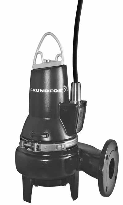
6 English (GB) 2. General description This booklet includes instructions for installation, operation and maintenance of Grundfos SL1 and SLV submersible sewage and wastewater pumps with motors of 0.9 to 1.5 kw. Grundfos SL1 and SLV sewage pumps are portable and designed for pumping domestic and industrial sewage and wastewater. Two types of pumps are available: SL sewage pumps with single-channel impeller SLV sewage pumps with Vortex, free-flow impeller. The pumps can be installed on an auto-coupling system or stand freely on the bottom of a tank. The pumps can be controlled via the Grundfos LC, LCD 107, LC, LCD 108, LC, LCD 110 pump controllers or the Grundfos CU 100 control box. See installation and operating instructions for the selected controller Fig. 2 SLV pump Explanation to figures 1 and 2: Pos. Description TM Product drawings 1 Cable plug 2 Nameplate Discharge 4 Discharge flange DN 65, PN Lifting bracket 6 Stator housing 7 Oil screw 3 8 Clamp 4 9 TM Pump housing Fig. 1 SL pump 24
7 2.2 Applications SL pumps are designed for pumping these liquids: large quantities of drainage and surface water domestic wastewater with discharge from toilets wastewater from commercial buildings without discharge from toilets sludge-containing industrial wastewater industrial process water. SLV pumps are designed for pumping these liquids: surface water with abrasive particles municipal sewage sewage from commercial buildings sludge- or fibre-containing industrial wastewater. The compact design makes the pumps suitable for both temporary and permanent installation. 2.3 Operating conditions The SL1 and SLV pumps are designed for intermittent operation (S3). When completely submerged in the pumped liquid, the pumps can also operate continuously (S1). See 9.2 Operating modes. Installation depth Maximum 10 metres below liquid level. Operating pressure Maximum: 6 bar. Intermittent operation Maximum 20 starts per hour. ph value SL1 and SLV pumps in permanent installations can be used for pumping liquids with a ph value between 4 and 10. Liquid temperature 0 C to +40 C. For short periods (maximum 15 minutes) a temperature of up to + 60 C is permissible (non-ex versions only). 3. Delivery and handling The pump may be transported and stored in a vertical or horizontal position. Make sure that it cannot roll or fall over. 3.1 Transportation All lifting equipment must be rated for the purpose and checked for damage before any attempts to lift the pump. The lifting equipment rating must under no circumstances be exceeded. The pump weight is stated on the pump nameplate. Always lift the pump by its lifting bracket or by means of a fork-lift truck if the pump is fixed on a pallet. Never lift the pump by means of the motor cable or the hose/pipe. The polyurethane-embedded plug prevents water from penetrating into the motor via the motor cable. 3.2 Storage During long periods of storage, the pump must be protected against moisture and heat. After a long period of storage, the pump should be inspected before it is put into operation. Make sure that the impeller can rotate freely. Pay special attention to the condition of the shaft seals and the cable entry. English (GB) Explosion-proof pumps must never pump liquids with a temperature higher than +40 C. Density and viscosity of pumped liquid When pumping liquids with a density and/or a kinematic viscosity higher than that of water, use motors with correspondingly higher outputs. 25
8 English (GB) 4. Identification 4.1 Nameplate The nameplate states the operating data and approvals applying to the pump. The nameplate is fixed with rivets to the side of the motor housing close to the cable entry. Fix the additional nameplate supplied with the pump close to the tank. TM Fig. 3 Nameplate Pos. Description Pos. Description 1 Ex mark 15 EN approval 2 Type designation 16 Maximum liquid temperature 3 Product number 17 Maximum flow rate 4 Production code (year/week) 18 Explosion protection 5 Maximum head 19 Enclosure class to IEC 6 Maximum installation depth 20 Rated speed 7 Number of phases 21 Frequency 8 Rated voltage, Δ 22 Rated current, Δ 9 Rated voltage, Y 23 Rated current, Y 10 Rated power input 24 Shaft power 11 Power factor 25 Insulation class 12 Starting capacitor 26 Run capacitor 13 Country of production 27 Weight without cable 14 CE mark 26
9 4.2 Type key Please note that not all combination options are available. Code Example SL EX SL Pump type Grundfos sewage/wastewater pumps English (GB) 1 V [ ] [ ] A Impeller type Single-channel impeller Free-flow impeller (SuperVortex) Semi-open impeller Pump passage Maximum solids size [mm] Pump discharge Nominal diameter of pump discharge port [mm] Output power, P2 P2 = Code number from type designation/10 [kw] Equipment Standard (without equipment) Pump equipped with a control box CU 100 [ ] EX Ex version Standard version of submersible sewage/wastewater pump Pump designed to the ATEX standard indicated or Australian standard, AS [ ] B 0C [ ] A B [ ] Number of poles 2-pole, 3000 min -1 Number of phases Single-phase motor Three-phase motor Mains frequency 50 Hz Voltage and starting method 230 V, DOL V, DOL V, DOL Generation 1st generation 2nd generation 3rd generation, etc The pumps belonging to the individual generations differ in design but are similar in terms of power rating. Material in pump Standard material in pump 27
10 English (GB) 5. Approvals The standard version of SL1 and SLV pumps has been tested by VDE, and the explosion-proof version approved by KEMA according to the ATEX directive. 5.1 Approval standards The standard variants are approved by LGA (notified body under the Construction Products Directive) according to EN or EN as specified on the pump nameplate. 5.2 Explanation to the Ex approval The explosion protection classification of the pump is CE 0344 II 2 G Ex d IIB T4 X. Directive/ standard Code Description ATEX Harmonized European standard EN CE 0344 II = CE marking of conformity according to the ATEX directive 94/9/EC, Annex X. = 0344 is the number of the notified body which has certified the quality system for ATEX. = Marking of explosion protection Equipment group according to the ATEX directive, Annex II, point 2.2, defining the requirements applicable to the equipment in this group. 2 = Equipment category according to the ATEX directive, Annex II, point 2.2, defining the requirements applicable to the equipment in this category. G = Explosive atmospheres caused by gases, vapours or mists. Ex = The equipment conforms to harmonized European standard. d = Flame-proof enclosure according to EN : II = Suitable for use in explosive atmospheres (not mines.) B = Classification of gases, see EN : 2006, Annex A. Gas group B includes gas group A. T4 = Maximum surface temperature is 135 C. X = The letter X in the certificate number indicates that the equipment is subject to special conditions for safe use. The conditions are mentioned in the certificate and the installation and operating instructions Australia Ex variants for Australia are approved as Ex nc II T3 X according to IEC (corresponding to AS ). Standard Code Description IEC 79-15: 1987 Ex = Area classification according to AS n = Non-sparking according to AS : 1991, section 3 (IEC 79-15: 1987). C = The environment is adequately protected against sparking components. II = Suitable for use in explosive atmospheres (not mines). T3 = Maximum surface temperature is 200 C. X = The letter X in the certificate number indicates that the equipment is subject to special conditions for safe use. The conditions are mentioned in the certificate and the installation and operating instructions. 28
11 6. Safety Pump installation in tanks must be carried out by specially trained persons. Work in or near tanks must be carried out according to local regulations. 6.1 Potentially explosive environments Use explosion-proof pumps for applications in potentially explosive environments. SL1 and SLV pumps must under no circumstance pump combustible liquids. English (GB) Persons must not enter the installation area when the atmosphere is explosive. It must be possible to lock the mains switch in position 0. Type and requirements as specified in EN , The use of this product requires experience with and knowledge of the product. Persons with reduced physical, sensory or mental capabilities must not use this product, unless they are under supervision or have been instructed in the use of the product by a person responsible for their safety. Children must not use or play with this product. For safety reasons, all work in tanks must be supervised by a person outside the pump tank. Note It is advisable to make all maintenance and service work when the pump is placed outside the tank. Tanks for submersible sewage and wastewater pumps may contain sewage or wastewater with toxic and/or disease-causing substances. Therefore, all persons involved must wear appropriate personal protective equipment and clothing, and all work on and near the pump must be carried out under strict observance of the hygiene regulations in force. Make sure that the lifting bracket is tightened before attempting to lift the pump. Tighten if necessary. Carelessness during lifting or transportation may cause injury to personnel or damage to the pump. The classification of the installation site must be approved by the local firefighting authorities in each individual case. The explosion protection classification of the pumps is CE II 2 G, Ex d IIB T4 X. The classification of the installation site must be approved by the local firefighting authorities in each individual case. Special conditions for safe use of SL1 and SLV explosion-proof pumps: 1. Bolts used for replacement must be class A2-70 or better according to EN/ISO The level of pumped liquid must be controlled by two stop level switches connected to the motor control circuit. The minimum level depends on the installation type and is specified in these installation and operating instructions. 3. Make sure the permanently attached cable is suitably mechanically protected and terminated in a suitable terminal board placed outside the potentially explosive area. 4. The thermal protection in the stator windings has a nominal cut-out temperature of 150 C guaranteeing the disconnection of the power supply; the resetting of the supply is manual. 29
12 English (GB) 7. Installation Caution Fit the extra nameplate supplied with the pump at the installation site or keep it in the cover of this booklet. All safety regulations must be observed at the installation site, e.g. the use of blowers for fresh-air supply to the tank. Prior to installation, check the oil level in the oil chamber. See section 10. Maintenance and service. The pumps are suitable for different installation types which are described in sections 7.1 Submerged installation on auto-coupling and 7.2 Free-standing submerged installation. All pump housings have a cast DN 65, PN 10 discharge flange. Note Caution Prior to installation, make sure the tank bottom is even. Before beginning the installation, switch off the power supply and lock the mains switch in position 0. Any external voltage connected to the pump must be switched off before working on the pump. The pumps are designed for intermittent operation. When completely submerged in the pumped liquid, the pumps can also operate continuously. See section 12. Technical data. Do not put your hands or any tool into the pump suction or discharge port after the pump has been connected to the power supply, unless the pump has been switched off by removing the fuses or switching off the mains switch. It must be ensured that the power supply cannot be accidentally switched on. We recommend to always use Grundfos accessories to avoid malfuncions due to incorrect installation. Only use the lifting bracket for lifting the pump. Do not use it to hold the pump when in operation. 7.1 Submerged installation on autocoupling Pumps for permanent installation can be installed on a stationary auto-coupling guide rail system. See fig. A, page 8. The auto-coupling system facilitates maintenance and service as the pump can easily be lifted out of the tank. Note Note Before beginning installation procedures, make sure that the atmosphere in the tank is not potentially explosive. Proceed as follows: 1. Drill mounting holes for the guide rail bracket on the inside of the tank and fasten the guide rail bracket provisionally with two screws. 2. Place the auto-coupling base unit on the bottom of the tank. Use a plumb line to establish the correct positioning. Fasten the auto coupling with expansion bolts. If the bottom of the tank is uneven, the auto-coupling base unit must be supported so that it is level when being fastened. 3. Assemble the discharge line in accordance with the generally accepted procedures and without exposing the line to distortion or tension. 4. Place the guide rails on the auto-coupling base unit and adjust the length of the rails accurately to the guide rail bracket at the top of the tank. 5. Unscrew the provisionally fastened guide rail bracket, fit it on top of the guide rails and finally fasten it firmly to the tank wall. Note Make sure that the pipework is installed without the use of undue force. No loads from the pipework weight must be carried by the pump. We recommend the use of loose flanges to ease the installation and to avoid pipe tension at flanges and bolts. Do not use elastic elements or bellows in the pipework; these elements should never be used as a means to align the pipework. The guide rails must not have any axial play as this would cause noise during pump operation. 6. Clean out debris from the tank before lowering the pump into the tank. 7. Fit the guide claw to the discharge port of the pump. 8. Slide the guide claw between the guide rails and lower the pump into the tank by means of a chain secured to the lifting bracket of the pump. When the pump reaches the auto-coupling base unit, the pump will automatically connect tightly. 30
13 9. Hang up the end of the chain on a suitable hook at the top of the tank and in such a way that the chain cannot come into contact with the pump housing. 10. Adjust the length of the motor cable by coiling it up on a relief fitting to ensure that the cable is not damaged during operation. Fasten the relief fitting to a suitable hook at the top of the tank. Make sure that the cables are not sharply bent or pinched. 11. Connect the motor cable and the monitoring cable, if any. Note The free end of the cable must not be submerged as water may penetrate through the cable into the motor. 7.2 Free-standing submerged installation Pumps for free-standing submerged installation can stand freely on the bottom of the tank or the like. See fig. B, page 9. In order to facilitate service on the pump, fit a flexible union or coupling to the elbow on the discharge line for easy separation. If a hose is used, make sure that the hose does not buckle and that the inside diameter of the hose matches that of the pump discharge port. If a rigid pipe is used, fit the union or coupling, nonreturn valve and isolating valve in the order mentioned, when viewed from the pump. If the pump is installed in muddy conditions or on uneven ground, we recommend to support the pump on bricks or a similar support. Proceed as follows: 1. Fit a 90 elbow to the pump discharge port and connect the discharge pipe/hose. 2. Lower the pump into the liquid by means of a chain secured to the lifting bracket of the pump. We recommend to place the pump on a plane, solid foundation. Make sure that the pump is hanging from the chain and not the cable. 3. Hang up the end of the chain on a suitable hook at the top of the tank and in such a way that the chain cannot come into contact with the pump housing. 4. Adjust the length of the motor cable by coiling it up on a relief fitting to ensure that the cable is not damaged during operation. Fasten the relief fitting to a suitable hook. Make sure that the cables are not sharply bent or pinched. 5. Connect the motor cable and the monitoring cable, if any. Note The free end of the cable must not be submerged as water may penetrate through the cable into the motor. 8. Electrical connection Connect the pump to an external mains switch which ensures all-pole disconnection with a contact separation according to EN , It must be possible to lock the mains switch in position 0. Type and requirements as specified in EN , The electrical connection must be carried out in accordance with local regulations. The pumps must be connected to a control box with a motor protection relay with IEC trip class 10 or 15. Pumps for hazardous locations must be connected to a control box with a motor protection relay with IEC trip class 10. Do not install Grundfos control boxes, pump controllers, Ex barriers and the free end of the power cable in potentially explosive environments. The explosion protection classification of the pump is CE II 2 G, Ex d IIB T4 X. The classification of the installation site must be approved by the local firefighting authorities in each individual case. On explosion-proof pumps, make sure that an external earth conductor is connected to the external earth terminal on the pump using a conductor with a secure cable clamp. Clean the surface of the external earth connection and mount the cable clamp. The cross section of the earth conductor must be at least 4 mm 2, e.g. type H07 V2-K (PVT 90 ) yellow/green. Make sure that the earth connection is protected against corrosion. Make sure that all protective equipment has been connected correctly. Float switches used in potentially explosive environments must be approved for this application. They must be connected to the Grundfos LC, LCD 108 pump controller via the intrinsically safe LC-Ex4 barrier to ensure a safe circuit. English (GB) 31
14 English (GB) Caution If the supply cable is damaged, it must be replaced by the manufacturer, its service agent or a similarly qualified person. Set the motor-protective circuit breaker to the rated current of the pump. The rated current is stated on the pump nameplate. If the pump has an Ex mark on the nameplate, make sure that the pump is connected in accordance with the instructions given in this booklet. The supply voltage and frequency are marked on the pump nameplate. The voltage tolerance must be within - 10 %/+ 6 % of the rated voltage. Make sure that the motor is suitable for the power supply available at the installation site. All pumps are supplied with 10 m cable and a free cable end. The pump must be connected to one of these two controller types: a control box with motor-protective circuit breaker, such as Grundfos CU 100 control box a Grundfos LC, LCD 107, LC, LCD 108 or LC, LCD 110 pump controller. See fig. 4 or 5 and the installation and operating instructions for the selected control box or pump controller. Potentially explosive environments In potentially explosive environments you have two options: Use float switches made for Ex environment and a safety barrier in combination with either DC, DCD or LC, LCD 108. Use air bells in combination with LC, LCD 107. Before installation and the first start-up of the pump, check the condition of the cable visually to avoid short circuits. For more information about the function of the thermal switches, see 8.4 Thermal switches. 8.1 Wiring diagrams Fig. 4 Fig. 5 PE Wiring diagram for single-phase pumps Wiring diagram for three-phase pumps 8.2 CU 100 control box L 4 5 PE N PE L1 L2 L3 T2 160 C 150 C The CU 100 control box incorporates a motorprotective circuit breaker and is available with level switch and cable. Single-phase pumps: A run capacitor must be connected to the control box. For capacitor size, see the table: Run capacitor Pump type [μf] [V] SL1 and SLV T1 T3 4 5 PE T2 T1 T3 170 C 150 C TM TM
15 Start and stop levels: The difference in level between start and stop can be adjusted by changing the free cable length. Long free cable = large difference in level Short free cable = small difference in level. Note Both the two following points must be observed. To prevent air intake and vibrations, install the stop level switch in such a way that the pump is stopped before the liquid level is lowered below the upper edge of the clamp on the pump. Install the start level switch in such a way that the pump is started at the required level; however, the pump must always be started before the liquid level reaches the bottom inlet pipe to the tank. The CU 100 control box must not be used for Ex applications. See section 8.3 Pump controllers. The pump must not run dry. An additional level switch must be installed to ensure that the pump is stopped in case the stop level switch is not operating. See fig. 6. The pump must be stopped when the liquid level reaches the upper edge of the clamp on the pump. Float switches used in potentially explosive environments must be approved for this application. They must be connected to the Grundfos DC, DCD or LC, LCD 108 pump controller via an intrinsically safe barrier to ensure a safe circuit. 8.3 Pump controllers The following LC and LCD pump controllers are available: LC controllers are for one-pump-installations and LCD controllers are for two-pump-installations. LC 107 and LCD 107 with air bells LC 108 and LCD 108 with float switches LC 110 and LCD 110 with electrodes. In the following description, "level switches" can be air bells, float switches or electrodes, depending on the pump controller selected. Controllers for single-phase pumps incorporate capacitors. The LC controller is fitted with two or three level switches: One for start and the other for stop of pump. The third level switch, which is optional, is for high-level alarm. The LCD controller is fitted with three or four level switches: One for common stop and two for start of the pumps. The fourth level switch, which is optional, is for high-level alarm. When installing the level switches, observe the following points: To prevent air intake and vibrations, install the stop level switch in such a way that the pump is stopped before the liquid level is lowered below the middle of the motor housing. Install the start level switch in such a way that the pump is started at the required level; however, the pump must always be started before the liquid level reaches the bottom inlet pipe to the tank. If installed, always install the high-level alarm switch about 10 cm above the start level switch; however, the alarm must always be given before the liquid level reaches the inlet pipe to the tank. For further information, see the installation and operating instructions for the pump controller selected. English (GB) Fig. 6 Start and stop levels Alarm Start Stop Additional stop TM The pump must not run dry. An additional level switch must be installed to ensure that the pump is stopped in case the stop level switch is not operating. The pump must be stopped when the liquid level reaches the upper edge of the clamp on the pump. Float switches used in potentially explosive environments must be approved for this application. They must be connected to the Grundfos DC, DCD or LC, LCD 108 pump controller via an intrinsically safe barrier to ensure a safe circuit. 33
16 English (GB) 8.4 Thermal switches All pumps have two sets of thermal switches incorporated in the stator windings. Thermal switch, circuit 1 (T1-T3), breaks the circuit at a winding temperature of approx. 150 C. Note This thermal switch must be connected for all pumps. Thermal switch, circuit 2 (T1-T2), breaks the circuit at a winding temperature of approx. 170 C (threephase pumps) or 160 C (single-phase pumps). After thermal cutout, explosion-proof pumps must be restarted manually. The thermal switch (circuit 2) must be connected for manual restarting of these pumps. Maximum operating current of the thermal switches is 0.5 A at 500 VAC and cos φ 0.6. The switches must be able to break a coil in the supply circuit. In the case of standard pumps, both thermal switches can (when closing the circuit after cooling) generate automatic restarting of the pump via the controller. The separate motor-protective circuit breaker/control box must not be installed in potentially explosive environments. 8.5 Frequency converter operation For frequency converter operation please observe the following information. Requirements must be fulfilled. Recommendations ought to be fulfilled. Consequences should be considered Requirements The thermal protection of the motor must be connected. Peak voltage and du/dt must be in accordance with the table below. The values stated are maximum values supplied to motor terminals. The cable influence has not been taken into account. See data sheet for the frequency converter used regarding the actual values and cable influence on the peak voltage and du/dt Recommendations Before installing a frequency converter, calculate the lowest allowable frequency in the installation in order to avoid zero flow. Do not reduce the motor speed to less than 30 % of rated speed. Keep the flow velocity above 1 m/sec. Let the pump run at rated speed at least once a day in order to prevent sedimentation in the piping system. Do not exceed the frequency indicated on the nameplate. In this case there is risk of motor overload. Keep the motor cable as short as possible. The peak voltage will increase with the length of the motor cable. See data sheet for the frequency converter used. Use input and output filters on the frequency converter. See data sheet for the frequency converter used. Use screened motor cable if there is a risk that electrical noise can disturb other electrical equipment. See data sheet for the frequency converter used Consequences When operating the pump via a frequency converter, please be aware of these possible consequences: The locked-rotor torque will be lower. How much lower will depend on the frequency converter type. See the installation and operating instructions for the frequency converter used for information on the locked-rotor torque available. The working condition of bearings and shaft seal may be affected. The possible effect will depend on the application. The actual effect cannot be predicted. The acoustic noise level may increase. See the installation and operating instructions for the frequency converter used for advice as to how to reduce the acoustic noise. Max. repetitive peak voltage (V) Max. du/dt U N 400 V (V/μ sec.) If the pump is an Ex-approved pump, check if the Ex certificate of the specific pump allows the use of frequency converter. Set the frequency converter U/f ratio according to the motor data. Local regulations/standards must be fulfilled. 34
17 9. Start-up Before starting work on the pump, make sure that the fuses have been removed or the mains switch has been switched off. It must be ensured that the power supply cannot be accidentally switched on. Make sure that all protective equipment has been connected correctly. The pump must not run dry. 9.2 Operating modes The pumps are designed for intermittent operation (S3). When completely submerged, the pumps can also operate continuously (S1). English (GB) 9.1 General start-up procedure Proceed as follows: 1. Remove the fuses and check that the impeller can rotate freely. Turn the impeller by hand. 2. Check the condition of the oil in the oil chamber. See also section 10.5 Oil change. 3. Check that the monitoring units, if used, are operating satisfactorily. 4. Check the setting of the air bells, float switches or electrodes. 5. Open the isolating valves, if fitted. 6. Lower the pump into the liquid and insert the fuses. 7. Check whether the system has been filled with liquid and vented. The pump is self-venting. 8. Start the pump. Caution The pump must not be started if the atmosphere in the tank is potentially explosive. It may lead to personal injuries or death to open the clamp while the pump is operating. In case of abnormal noise or vibrations from the pump, other pump failure or power supply failure, stop the pump immediately. Do not attempt to restart the pump until the cause of the fault has been found and the fault corrected. After one week of operation or after replacement of the shaft seal, check the condition of the oil in the chamber. See section 10. Maintenance and service for procedure. Fig. 7 Operating levels S3, intermittent operation Operating mode S3 means that within 10 minutes the pump must be in operation for 4 minutes and stopped for 6 minutes. See fig. 8. In this operating mode, the pump is partly submerged in the pumped liquid, i.e. the liquid level reaches at minimum the middle of the motor. See fig. 7. Operation Stop Fig. 8 S3 operation S1, continuous operation In this operating mode, the pump can operate continuously without being stopped for cooling. Being completely submerged, the pump is sufficiently cooled by the surrounding liquid. See fig. 7. P P 4 min. 10 min. 6 min. S1 S3 t TM TM Operation Stop t TM Fig. 9 S1 operation 35
18 English (GB) 9.3 Direction of rotation Note The pump may be started for a very short period without being submerged to check the direction of rotation. All single-phase pumps are factory-wired for the correct direction of rotation. Before starting up three-phase pumps, check the direction of rotation. An arrow on the motor housing indicates the correct direction of rotation. Correct direction of rotation is clockwise when viewed from above. When started, the pump will jerk in the opposite direction of the direction of rotation. If the direction of rotation is wrong, interchange any two of the phases in the power supply cable. See fig. 4 or 5. Checking the direction of rotation The direction of rotation should be checked in one of the following ways every time the pump is connected to a new installation. Procedure 1: 1. Start the pump and check the flow of liquid or the discharge pressure. 2. Stop the pump and interchange any two of the phases in the power supply cable. 3. Restart the pump and check the quantity of liquid or the discharge pressure. 4. Stop the pump. 5. Compare the results taken under points 1 and 3. The connection which gives the larger quantity of liquid or the higher pressure is the correct direction of rotation. Procedure 2: 1. Let the pump hang from a lifting device, e.g. the hoist used for lowering the pump into the tank. 2. Start and stop the pump while observing the movement (jerk) of the pump. 3. If connected correctly, the pump will jerk in the opposite direction of the direction of rotation. See fig If the direction of rotation is wrong, interchange any two of the phases in the power supply cable. See fig. 4 or 5. Fig. 10 Jerk direction 10. Maintenance and service Before starting work on the pump, make sure that the fuses have been removed or the mains switch has been switched off. It must be ensured that the power supply cannot be accidentally switched on. All rotating parts must have stopped moving. Except for service on the pump parts, all other service work must be carried out by Grundfos or a service workshop authorized by Grundfos. Before carrying out maintenance and service, make sure that the pump has been thoroughly flushed with clean water. Rinse the pump parts in water after dismantling. When loosening the screws of the oil chamber, note that pressure may have built up in the chamber. Do not remove the screws until the pressure has been fully relieved. TM
19 10.1 Inspection Pumps running normal operation should be checked every 3000 operating hours or at least once a year. If the dry solids content of the pumped liquid is very high or sandy, check the pump at shorter intervals. Check the following points: Power consumption See pump nameplate. Oil level and oil condition When the pump is new or after replacement of the shaft seal, check the oil level after one week of operation. If the pump has been in operation for a long period of time, if the oil is drained off shortly after the pump has been stopped, and if the oil is greyish white like milk, it contains water. If there is more than 20 % extra liquid (water) in the oil chamber, the shaft seal is defective. See section 10.4 Replacing the shaft seal. In any case, the oil should be changed after 3000 operating hours or once a year. Use Shell Ondina 917 oil or similar type. See sections 10.5 Oil change and 10.6 Service kits. The oil chamber of all pump models holds 0.17 litre Adjusting the impeller clearance This section applies to SL1 pumps only. For position numbers, see page 16. Proceed as follows: 1. Loosen the locking screws (pos. 188b). 2. Loosen the adjusting screws (pos. 189) and push the wear plate (pos. 162) until it touches the impeller. 3. Tighten the adjusting screws so that the wear plate still touches the impeller. Then loosen all the adjusting screws about half a turn. Note The impeller must be able to rotate freely without touching the wear plate. 4. Tighten the locking screws. 5. Rotate the impeller by hand to check that it is not touching the wear plate. See also section 10.3 Cleaning the pump housing. English (GB) Note Used oil must be disposed of in accordance with local regulations. Cable entry Make sure that the cable entry is watertight and that the cables are not sharply bent and/or pinched. See section 10.6 Service kits. Pump parts Check impeller, pump housing, etc. for possible wear. Replace defective parts. See section 10.6 Service kits. Ball bearings Check the shaft for noisy or heavy operation (turn the shaft by hand). Replace defective ball bearings. A general overhaul of the pump is usually required in case of defective ball bearings or poor motor function. This work must be carried out by Grundfos or a service workshop authorized by Grundfos. Fig. 11 Pump viewed from suction port 10.3 Cleaning the pump housing For position numbers, see page 16 or 17. Proceed as follows: Dismantling 1. Stand the pump upright. 2. Loosen and remove the clamp (pos. 92) joining pump housing and motor. 3. Lift the motor part out of the pump housing (pos. 50). As the impeller is fastened to the shaft end, the impeller is removed together with the motor part. 4. Clean the pump housing and the impeller. Assembly 1. Place the motor part with impeller in the pump housing. 2. Fit and tighten the clamp. See also section 10.4 Replacing the shaft seal. TM
20 English (GB) 10.4 Replacing the shaft seal As described in section 10.1 Inspection, the oil check will reveal whether the shaft seal is intact. If the oil contains more than 20 % water, it is an indication that the shaft seal is defective and must be replaced. If the shaft seal is not replaced, the motor will be damaged. For position numbers, see page 16 or 17. Proceed as follows: 1. Loosen and remove the clamp (pos. 92) joining pump housing and motor. 2. Lift the motor part out of the pump housing (pos. 50). As the impeller is fastened to the shaft end, the impeller is removed together with the motor part. 3. Remove the screw (pos. 188a) from the shaft end. 4. Remove the impeller (pos. 49) from the shaft. 5. If it was not already done, drain the oil from the oil chamber. See section 10.5 Oil change. The shaft seal is a complete unit for all pumps. 6. Remove the screws (pos. 188a) securing the shaft seal (pos. 105). 7. Lift the shaft seal (pos. 105) out of the oil chamber using the lever principle, the two dismounting holes in the shaft seal carrier (pos. 58) and two screwdrivers. 8. Check the bush (pos. 103). If the bush is worn and must be replaced, the pump must be checked by Grundfos or a service workshop authorized by Grundfos. If the bush is intact, proceed as follows: 1. Check and clean the oil chamber. 2. Lubricate the faces in contact with the shaft seal with oil. 3. Insert the new shaft seal (pos. 105) using the plastic bush included in the kit. 4. Tighten the screws (pos. 188a) securing the shaft seal to 16 Nm. 5. Fit the impeller. Make sure that the key (pos. 9a) is fitted correctly. 6. Fit and tighten the screw (pos. 188a) securing the impeller to 22 Nm. 7. Place the motor part with impeller in the pump housing (pos. 50). 8. Fit and tighten the clamp (pos. 92). 9. Fill the oil chamber with oil. See section 10.5 Oil change. For adjustment of impeller clearance, see section 10.2 Adjusting the impeller clearance Oil change After 3000 operating hours or once a year, change the oil in the oil chamber as described below. If the shaft seal has been changed, the oil must be changed as well. See section 10.4 Replacing the shaft seal. Draining of oil 1. Loosen and remove both oil screws to allow all the oil to drain from the chamber. 2. Check the oil for water and impurities. If the shaft seal has been removed, the oil will give a good indication of the condition of the shaft seal. Note Oil filling, pump lying down See fig Place the pump in such a position that it is lying on the motor housing and the discharge flange with the oil screws pointing upwards. 2. Fill oil into the oil chamber through the upper hole until it starts running out of the lower hole. The oil level is now correct. For oil quantity, see section 10.1 Inspection. 3. Fit both oil screws using the packing material included in the kit. See section 10.6 Service kits. Oil level When loosening the screws of the oil chamber, note that pressure may have built up in the chamber. Do not remove the screws until the pressure has been fully relieved. Used oil must be disposed of in accordance with local regulations. Oil filling Fig. 12 Oil filling holes Oil filling, pump in upright position 1. Place the pump on a plane, horizontal surface. 2. Fill oil into the oil chamber through one of the holes until it starts running out of the other hole. For oil quantity, see section 10.1 Inspection. 3. Fit both oil screws using the packing material included in the kit. See section 10.6 Service kits. TM
21 10.6 Service kits Before starting work on the pump, make sure that the fuses have been removed or the mains switch has been switched off. It must be ensured that the power supply cannot be accidentally switched on. All rotating parts must have stopped moving. The following service kits are available for all pumps. English (GB) Service kit Contents Pump type Material Shaft seal O-ring Impeller Oil Shaft seal complete O-rings and gaskets for oil screws Impeller complete with adjusting screw, shaft screw and key 1 litre of oil, type Shell Ondina 917. See section 10. Maintenance and service for required quantity in oil chamber. Order number All BQQP All BQQV All NBR All FKM SL SL SL SLV SLV SLV All types Note A possible replacement of the cable must be carried out by Grundfos or a service workshop authorized by Grundfos Contaminated pumps If a pump has been used for a liquid which is injurious to health or toxic, the pump will be classified as contaminated. If Grundfos is requested to service the pump, Grundfos must be contacted with details about the pumped liquid, etc. before the pump is returned for service. Otherwise Grundfos can refuse to accept the pump for service. Possible costs of returning the pump are paid by the customer. However, any application for service (no matter to whom it may be made) must include details about the pumped liquid if the pump has been used for liquids which are injurious to health or toxic. The pump must be cleaned in the best possible way before it is returned. 39
22 English (GB) 11. Fault finding Before attempting to diagnose any fault, make sure that the fuses have been removed or the mains switch has been switched off. It must be ensured that the power supply cannot be accidentally switched on. All rotating parts must have stopped moving. All regulations applying to pumps installed in potentially explosive environments must be observed. It must be ensured that no work is carried out in potentially explosive atmosphere. Fault Cause Remedy 1. Motor does not start. Fuses blow or motor-protective circuit breaker trips out immediately. Caution: Do not start again! 2. Pump operates, but motorprotective circuit breaker trips out after a short while. 3. The pump s thermal switch trips out after the pump has been operating for some time. 4. Pump operates at belowstandard performance and power consumption. 5. Pump operates, but gives no liquid. a) Supply failure; short-circuit; earth-leakage fault in cable or motor winding. b) Fuses blow due to use of wrong type of fuse. Have the cable and motor checked and repaired by a qualified electrician. Install fuses of the correct type. c) Impeller blocked by impurities. Clean the impeller. d) Air bell, float switch or electrode out of adjustment or defective. a) Low setting of thermal relay in motor-protective circuit breaker. b) Increased current consumption due to large voltage drop. c) Impeller blocked by impurities. Increased current consumption in all three phases. d) Adjustment of impeller clearance incorrect. Readjust or replace the air bells, float switches or electrodes. Set the relay in accordance with the specifications on the nameplate. Measure the voltage between two motor phases. Tolerance: - 10 %/+ 6 %. Reestablish correct voltage supply. Clean the impeller. Readjust the impeller. See section 10.2 Adjusting the impeller clearance, fig. 11. a) Too high liquid temperature. Reduce the liquid temperature. b) Too high liquid viscosity. Dilute the liquid. c) Wrong electrical connection (If the pump is star-connected to a delta connection, the result will be very low undervoltage). Check and correct the electrical installation. a) Impeller blocked by impurities. Clean the impeller. b) Wrong direction of rotation. Check the direction of rotation and possibly interchange any two phases of the incoming supply cable. See section 9.3 Direction of rotation. a) Discharge valve closed or blocked. Check the discharge valve and possibly open and/or clean. b) Non-return valve blocked. Clean the non-return valve. c) Air in pump. Vent the pump. 40
23 12. Technical data Supply voltage 1 x 230 V - 10 %/+ 6 %, 50 Hz 3 x 230 V - 10 %/+ 6 %, 50 Hz 3 x 400 V - 10 %/+ 6 %, 50 Hz. Winding resistances 13. Disposal This product or parts of it must be disposed of in an environmentally sound way: 1. Use the public or private waste collection service. 2. If this is not possible, contact the nearest Grundfos company or service workshop. English (GB) Motor size Winding resistance * Single-phase [kw] Starting winding Main winding Ω 2.75 Ω Three-phase 3 x 230 V 3 x 400 V 6.8 Ω 9.1 Ω * The table values do not include the cable. Resistance in cables: 2 x 10 m, approx Ω. Enclosure class IP68, according to IEC Ex protection CE II 2 G, Ex d IIB T4 X, according to EN : Insulation class F (155 C). Pump curves Pump curves are available via the internet at The curves are to be considered as a guide. They must not be used as guarantee curves. Test curves for the supplied pump are available on request. Sound pressure level The sound pressure level of the pumps is lower than the limiting values stated in the EC Council directive 98/37/EC relating to machinery. Subject to alterations. 41
24 补充 Fig. A 42
25 补充 Fig. B 43
26 补充 44
27 补充 Fig. C SL1.50 水泵爆炸图 45
28 补充 Fig. D SLV.65 水泵爆炸图 46
29 格兰富所属公司 Argentina Bombas GRUNDFOS de Argentina S.A. Ruta Panamericana km Lote 34A Garin Pcia. de Buenos Aires Phone: Telefax: Australia GRUNDFOS Pumps Pty. Ltd. P.O. Box 2040 Regency Park South Australia 5942 Phone: Telefax: Austria GRUNDFOS Pumpen Vertrieb Ges.m.b.H. Grundfosstraße 2 A-5082 Grödig/Salzburg Tel.: Telefax: Belgium N.V. GRUNDFOS Bellux S.A. Boomsesteenweg B-2630 Aartselaar Tél.: Télécopie: Belorussia Представительство ГРУНДФОС в Минске , Минск, ул. В. Хоружей, 22, оф Тел.: +(37517) , Факс: +(37517) grundfos_minsk@mail.ru Bosnia/Herzegovina GRUNDFOS Sarajevo Trg Heroja 16, BiH Sarajevo Phone: Telefax: grundfos@bih.net.ba Brazil BOMBAS GRUNDFOS DO BRASIL Av. Humberto de Alencar Castelo Branco, 630 CEP São Bernardo do Campo - SP Phone: Telefax: Bulgaria Grundfos Bulgaria EOOD Slatina District Iztochna Tangenta street no. 100 BG Sofia Tel Fax bulgaria@grundfos.bg Canada GRUNDFOS Canada Inc Brighton Road Oakville, Ontario L6H 6C9 Phone: Telefax: China GRUNDFOS Pumps (Shanghai) Co. Ltd. 50/F Maxdo Center No. 8 XingYi Rd. Hongqiao development Zone Shanghai PRC Phone: Telefax: Croatia GRUNDFOS CROATIA d.o.o. Cebini 37, Buzin HR Zagreb Phone: Telefax: Czech Republic GRUNDFOS s.r.o. Čajkovského Olomouc Phone: Telefax: Denmark GRUNDFOS DK A/S Martin Bachs Vej 3 DK-8850 Bjerringbro Tlf.: Telefax: info_gdk@grundfos.com Estonia GRUNDFOS Pumps Eesti OÜ Peterburi tee 92G Tallinn Tel: Fax: Finland OY GRUNDFOS Pumput AB Mestarintie 11 FIN Vantaa Phone: Telefax: France Pompes GRUNDFOS Distribution S.A. Parc d Activités de Chesnes 57, rue de Malacombe F St. Quentin Fallavier (Lyon) Tél.: Télécopie: Germany GRUNDFOS GMBH Schlüterstr Erkrath Tel.: +49-(0) Telefax: +49-(0) infoservice@grundfos.de Service in Deutschland: kundendienst@grundfos.de Greece GRUNDFOS Hellas A.E.B.E. 20th km. Athinon-Markopoulou Av. P.O. Box 71 GR Peania Phone: Telefax: Hong Kong GRUNDFOS Pumps (Hong Kong) Ltd. Unit 1, Ground floor Siu Wai Industrial Centre Wing Hong Street & 68 King Lam Street, Cheung Sha Wan Kowloon Phone: / Telefax: Hungary GRUNDFOS Hungária Kft. Park u. 8 H-2045 Törökbálint, Phone: Telefax: India GRUNDFOS Pumps India Private Limited 118 Old Mahabalipuram Road Thoraipakkam Chennai Phone: Indonesia PT GRUNDFOS Pompa Jl. Rawa Sumur III, Blok III / CC-1 Kawasan Industri, Pulogadung Jakarta Phone: Telefax: / Ireland GRUNDFOS (Ireland) Ltd. Unit A, Merrywell Business Park Ballymount Road Lower Dublin 12 Phone: Telefax: Italy GRUNDFOS Pompe Italia S.r.l. Via Gran Sasso 4 I Truccazzano (Milano) Tel.: Telefax: / Japan GRUNDFOS Pumps K.K. Gotanda Metalion Bldg., 5F, , Higashi-gotanda Shiagawa-ku, Tokyo Japan Phone: Telefax: Korea GRUNDFOS Pumps Korea Ltd. 6th Floor, Aju Building Yeoksam-dong, Kangnam-ku, Seoul, Korea Phone: Telefax: Latvia SIA GRUNDFOS Pumps Latvia Deglava biznesa centrs Augusta Deglava ielā 60, LV-1035, Rīga, Tālr.: , Fakss: Lithuania GRUNDFOS Pumps UAB Smolensko g. 6 LT Vilnius Tel: Fax: Malaysia GRUNDFOS Pumps Sdn. Bhd. 7 Jalan Peguam U1/25 Glenmarie Industrial Park Shah Alam Selangor Phone: Telefax: México Bombas GRUNDFOS de México S.A. de C.V. Boulevard TLC No. 15 Parque Industrial Stiva Aeropuerto Apodaca, N.L Phone: Telefax: Netherlands GRUNDFOS Netherlands Veluwezoom AE Almere Postbus CA ALMERE Tel.: Telefax: info_gnl@grundfos.com New Zealand GRUNDFOS Pumps NZ Ltd. 17 Beatrice Tinsley Crescent North Harbour Industrial Estate Albany, Auckland Phone: Telefax: Norway GRUNDFOS Pumper A/S Strømsveien 344 Postboks 235, Leirdal N-1011 Oslo Tlf.: Telefax: Poland GRUNDFOS Pompy Sp. z o.o. ul. Klonowa 23 Baranowo k. Poznania PL Przeźmierowo Tel: (+48-61) Fax: (+48-61) Portugal Bombas GRUNDFOS Portugal, S.A. Rua Calvet de Magalhães, 241 Apartado 1079 P Paço de Arcos Tel.: Telefax: România GRUNDFOS Pompe România SRL Bd. Biruintei, nr 103 Pantelimon county Ilfov Phone: Telefax: romania@grundfos.ro Russia ООО Грундфос Россия, Москва, ул. Школьная 39 Тел. (+7) , Факс (+7) , grundfos.moscow@grundfos.com Serbia GRUNDFOS Predstavništvo Beograd Dr. Milutina Ivkovića 2a/29 YU Beograd Phone: / Telefax: Singapore GRUNDFOS (Singapore) Pte. Ltd. 24 Tuas West Road Jurong Town Singapore Phone: Telefax: Slovenia GRUNDFOS d.o.o. Šlandrova 8b, SI-1231 Ljubljana- Črnuče Phone: Telefax: slovenia@grundfos.si South Africa Corner Mountjoy and George Allen Roads Wilbart Ext. 2 Bedfordview 2008 Phone: (+27) Fax: (+27) lsmart@grundfos.com Spain Bombas GRUNDFOS España S.A. Camino de la Fuentecilla, s/n E Algete (Madrid) Tel.: Telefax: Sweden GRUNDFOS AB Box 333 (Lunnagårdsgatan 6) Mölndal Tel.: +46(0) Telefax: +46(0) Switzerland GRUNDFOS Pumpen AG Bruggacherstrasse 10 CH-8117 Fällanden/ZH Tel.: Telefax: Taiwan GRUNDFOS Pumps (Taiwan) Ltd. 7 Floor, 219 Min-Chuan Road Taichung, Taiwan, R.O.C. Phone: Telefax: Thailand GRUNDFOS (Thailand) Ltd. 92 Chaloem Phrakiat Rama 9 Road, Dokmai, Pravej, Bangkok Phone: Telefax: Turkey GRUNDFOS POMPA San. ve Tic. Ltd. Sti. Gebze Organize Sanayi Bölgesi Ihsan dede Caddesi, 2. yol 200. Sokak No Gebze/ Kocaeli Phone: Telefax: satis@grundfos.com Ukraine ТОВ ГРУНДФОС УКРАЇНА Київ, Вул. Московська 8б, Тел.:( ) Фах.: ( ) ukraine@grundfos.com United Arab Emirates GRUNDFOS Gulf Distribution P.O. Box Jebel Ali Free Zone Dubai Phone: Telefax:
GRUNDFOS ILLUSTRATED SERVICE INSTRUCTIONS. Large SP SP 17, 30, 46, 60, 77, 95, 125, 160, 215
 GRUNDFOS ILLUSTRATED SERVICE INSTRUCTIONS Large SP SP 17, 30, 46, 60, 77, 95, 125, 160, 215 Contents PAGE SP 46 and 60... 2 SP 125 and 160... 5 SP 215... 7 SP 17 and 30... 10 SP 77 and 95... 18 1 SP 46
GRUNDFOS INSTRUCTIONS CR, CRI, CRN, CRT. ATEX-approved pumps Installation and operating instructions
 GRUNDFOS INSTRUCTIONS,,, T ATEX-approved pumps Installation and operating instructions Declaration of Conformity We, Grundfos, declare under our sole responsibility that the products,, and T, to which
GRUNDFOS INSTRUCTIONS CM, CME. Service instructions
 GRUNDFOS INSTRUCTIONS CM, CME Service instructions 2 English (GB) Service instructions Original service instructions. CONTENTS Page 1. Symbols used in this document 3 2. Type identification 4 2.1 Nameplate
GRUNDFOS INSTRUCTIONS MMS 6. Service instructions
 GRUNDFOS INSTRUCTIONS MMS 6 Service instructions English (GB) English (GB) Service instructions Original service instructions. CONTENTS 1. Symbols used in this document Page 1. Symbols used in this document
INSTRUCTIONS DWK. Installation and operating instructions. manufactured for Grundfos
 INSTRUCTIONS DWK Installation and operating instructions manufactured for Grundfos Declaration of Conformity We, Grundfos, declare under our sole responsibility that the product DWK, to which this declaration
TP, TPD union and low head
 GRUNDFOS INSTRUCTIONS TP, TPD union and low head 50/60 Hz 1/3~ Service instructions English (GB) English (GB) Service instructions Original service instructions. CONTENTS 1. Symbols used in this document
CR, CRI, CRN 1s, 1, 3, 5, 10, 15, 20 CR, CRN 32, 45, 64, 90, 120, 150
 GRUNDFOS INSTRUCTIONS, I, N 1s, 1, 3, 5, 10, 15, 20, N 32, 45, 64, 90, 120, 150 Double seal (tandem) Installation and operating instructions 2 nglish (GB) Installation and operating instructions Original
GRUNDFOS INSTRUCTIONS SEG AUTO ADAPT kw 50 Hz. Installation and operating instructions
 GRUNDFOS INSTRUCTIONS SEG AUTO ADAPT 0.9-4.0 kw 50 Hz Installation and operating instructions English (GB) English (GB) Installation and operating instructions Original installation and operating instructions
GRUNDFOS INSTRUCTIONS. Installation and operating instructions
 GRUNDFOS INSTRUCTIONS JP Installation and operating instructions English (GB) English (GB) Installation and operating instructions Original installation and operating instructions. CONTENTS Page 1. Symbols
SE1 50, 80, 100 SEV 65, 80, 100
 GRUNDFOS INSTRUCTIONS SE1 50, 80, 100 SEV 65, 80, 100 Installation and operating instructions English (GB) English (GB) Installation and operating instructions Original installation and operating instructions
GRUNDFOS INSTRUCTIONS SP 7/9/11/14. Service instructions
 GRUNDFOS INSTRUCTIONS SP 7/9/11/14 Service instructions English (GB) English (GB) Service instructions Original service instructions. CONTENTS Page 1. Symbols used in this document 2 2. Identification
GRUNDFOS INSTRUCTIONS SMG. 50/60 Hz DIN/ANSI. Service instructions
 GRUNDFOS INSTRUCTIONS SMG 50/60 Hz DIN/ANSI Service instructions English (GB) English (GB) Service instructions Original service instructions. CONTENTS Page 1. Symbols used in this document 2 2. Identification
CMB, CMB-SP Booster PM2
 CMB, CMB-SP Booster PM2 Supplement to Quick Guide GRUNDFOS INSTRUCTIONS English (GB) English (GB) Installation and operating instructions Supplement to quick guide. CONTENTS Page 1. Symbols used in this
GRUNDFOS INSTRUCTIONS. UPE Series 2000 UPE(D) FZ, UPE FZ. Installation and operating instructions
 FZ, UPE FZ. Installation and operating instructions") GRUNDFOS INSTRUCTIONS UPE Series 2000 UPE(D) 80-120 FZ, UPE 100-120 FZ Installation and operating instructions UPE Series 2000 Declaration of Conformity.......................................... 4 English
GRUNDFOS INSTRUCTIONS UPE Series 2000 UPE(D) 80-120 FZ, UPE 100-120 FZ Installation and operating instructions UPE Series 2000 Declaration of Conformity.......................................... 4 English
GRUNDFOS INSTRUCTIONS SCALA. Installation and operating instructions
 GRUNDFOS INSTRUCTIONS SCALA Installation and operating instructions English (GB) English (GB) Installation and operating instructions Original installation and operating instructions. These installation
GRUNDFOS INSTRUCTIONS MTC. Installation and operating instructions
 GRUNDFOS INSTRUCTIONS MTC Installation and operating instructions LIMITED WARRANTY Products manufactured by GRUNDFOS PUMPS CORPORATION (Grundfos) are warranted to the original user only to be free of defects
Cranes for SMD, SMG, SFG, SRG, AMD, AMG, AFG and SRP
 GRUNDFOS INSTRUCTIONS Cranes for SMD, SMG, SFG, SRG, AMD, AMG, AFG and SRP Installation and operating instructions Installation and operating instructions Original installation and operating instructions
GRUNDFOS INSTRUCTIONS. MGE model F. Service instructions
 GRUNDFOS INSTRUCTIONS MGE model F Service instructions Preface These service instructions describe fault finding of pumps with Grundfos motors, type MGE model F (hereafter called MGE-F). The service instructions
Installation and operating instructions
 GRUNDFOS INSTRUCTIONS CM Installation and operating instructions Installation and operating instructions http://net.grundfos.com/qr/i/95121197 Quick Guide (CM) http://net.grundfos.com/qr/i/95121198 Quick
Unilift KP 150, KP 250, KP 350
 GRUNDFOS INSTRUCTIONS Unilift KP 150, KP 250, KP 350 Installation and operating instructions DRAINAGE PUMP 1Z28 LIMITED WARRANTY Products manufactured by GRUNDFOS PUMPS CORPORATION (Grundfos) are warranted
GRUNDFOS INSTRUCTIONS. SEG AUTO Adapt kw, DIN, 50 Hz. Service instructions
 GRUNDFOS INSTRUCTIONS SEG AUTO Adapt 0.9-4.0 kw, DIN, 50 Hz Service instructions Service instructions Original service instructions CONTENTS Page 1. Symbols used in this document 2 2. Returning the product
GRUNDFOS INSTRUCTIONS NK, NKG. ATEX-approved pumps. Installation and operating instructions
 GRUNDFOS INSTRUCTIONS NK, NKG ATEX-approved pumps Installation and operating instructions NK, NKG English (GB) Installation and operating instructions...........................................................
GRUNDFOS INSTRUCTIONS MS6000. Submersible motors. Service instructions
 GRUNDFOS INSTRUCTIONS MS6000 Submersible motors Service instructions English (GB) English (GB) Service instructions Original service instructions. CONTENTS Page 1. Symbols used in this document 2 2. General
GRUNDFOS INSTRUCTIONS SCALA. Installation and operating instructions
 GRUNDFOS INSTRUCTIONS SCALA Installation and operating instructions English (GB) English (GB) Installation and operating instructions Original installation and operating instructions These installation
Installation instructions
 www.somfy.com Sonesse 0 DCT Installation instructions Ref :505080A Please read installation instructions and programming instructions completely prior to proceeding with installation and programming. Failure
ISO Interface. Large capacity. Light weight. Accommodates enclosure IP65. Solenoid Valve (with M Connector) Conforming to ISO
 Conforming to ISO") P-EX01-A Solenoid Valve (with M Connector) Conforming to ISO 1507-1, Large capacity EVS1-01 (Size: 01) EVS1-0 (Size: 0) Light weight Size 01 (-position): 0.6kg Size 0 (-position): 0.18kg Flow rate 1000L/min
P-EX01-A Solenoid Valve (with M Connector) Conforming to ISO 1507-1, Large capacity EVS1-01 (Size: 01) EVS1-0 (Size: 0) Light weight Size 01 (-position): 0.6kg Size 0 (-position): 0.18kg Flow rate 1000L/min
SMART Digital S - DDE
 GRUNDFOS INSTRUCTIONS SMART Digital S - DDE up to 15 l/h Installation and operating instructions Further languages http://net.grundfos.com/qr/i/95725839 English (GB) English (GB) Installation and operating
DOUBLE OCTOMILL TM PRODUCT RANGE
 DOUBLE OCTOMILL TM PRODUCT RANGE Double Octomill insert selection and cutting data recommendations, see page 6. complete insert programme, see page 7. Tool angles: Jo = -11q Jp = - 8q Jf = - 8q Pitch
GRUNDFOS INSTRUCTIONS. Grundfos ALPHA Installation and operating instructions
 GRUNDFOS INSTRUCTIONS Grundfos ALPHA Installation and operating instructions LIMITED WARRANTY Products manufactured by GRUNDFOS PUMPS CORPORATION (Grundfos) are warranted to the original user only to be
Roll Up WireFree IR. Installation instructions
 www.somfy.com TM Roll Up WireFree IR Installation instructions Ref :5059844 Safety This Somfy product must be installed by a professional motorization and home automation installer, for whom these instructions
Submersible Tank Pump
 Submersible Tank Pump Applications: Silent household pressure systems, garden irrigation, or water transfer. Performance Outline Pump Features High efficiency moulded impellers Stainless steel construction,
SL1, SLV kw, 50 Hz GRUNDFOS INSTRUCTIONS. Service instructions
 GRUNDFOS INSTRUCTIONS SL1, SLV 1.1-11 kw, 50 Hz Service instructions Installation and operating instructions in English and other languages for 50 Hz http://net.grundfos.com/qr/i/96771279 English (GB)
SBS-Control. Table of contents. Operating Instructions BKS24-9A. Operating Instructions
 Operating Instructions BKS24-9A Operating Instructions BKS24-9A Table of contents Operating Instructions 1 Operating controls and indicators 2 2 Preparations for faultless commissioning and operating 3
Packing Data Installation Instructions
 Packing Data PK Installation Instructions This document describes how to install a Dataliner DL10 display in a panel or enclosure and connect power. European Union Directive Compliance wiring and safety
SL B. Grundfos pump GRUNDFOS DATA BOOKLET
 GRUNDFOS DATA BOOKLET SL1.50.65.09.2.50B Grundfos pump 96106566 Thank you for your interest in our products. Please contact us for more information, or visit our website https://www.lenntech.com/grundfos/sl1000/96106566/sl1-50-65-09-2-50b.html
AUSTRIA. Table 1. FDI flows in the host economy, by geographical origin. (Millions of US dollars)
") Table 1. FDI flows in the host economy, by geographical origin World 5 690 138 6 195 3 184 10 784 7 933 31 154 6 858 9 303 840 10 618 5 760 Developed economies 5 740 13 5 341 2 689 10 137 6 291 29 721
Table 1. FDI flows in the host economy, by geographical origin World 5 690 138 6 195 3 184 10 784 7 933 31 154 6 858 9 303 840 10 618 5 760 Developed economies 5 740 13 5 341 2 689 10 137 6 291 29 721
GRUNDFOS INSTRUCTIONS. UPS, UPSD Series 200. Installation and operating instructions. Other languages.
 GRUDFOS ISTRUCTIOS UPS, UPSD Series 200 Installation and operating instructions Other languages http://net.grundfos.com/qr/i/96459997 English (GB) English (GB) Installation and operating instructions Original
GRUNDFOS INSTRUCTIONS. SMART Digital - DDC. Installation and operating instructions
 GRUNDFOS INSTRUCTIONS SMART Digital - DDC Installation and operating instructions Declaration of conformity Declaration of conformity GB Declaration of Conformity We, Grundfos Alldos, declare under our
Lifting Instructions for 1336 PLUS and FORCE D Frame Drives
 Installation Instructions Lifting Instructions for 1336 PLUS and FORCE D Frame Drives This publication will guide you through the steps needed to properly lift and mount the following drives: 1336 PLUS
UAE draft regulation for Electric Vehicle
 UAE draft regulation for Electric Vehicle Emirates Authority for Standardization and Metrology Eng. Khaled Ali Abdullmajeed Contents - Introduction of ESMA. - Introduction of EV Regulation in UAE - The
SEV D. Grundfos Pump GRUNDFOS DATA BOOKLET
 GRUNDFOS DATA BOOKLET SEV.6.6...1D Grundfos Pump 96779 Thank you for your interest in our products Please contact us for more information, or visit our website https://www.lenntech.com/grundfos/sev/96779/sev-6-6---1d.html
Dry installed pump type LANDY BTP.
 OPERATION & MAINTENANCE MANUAL Dry installed pump type LANDY BTP. Landustrie Sneek BV Pieter Zeemanstraat 6 Tel. 0031 515-486888 P.O. BOX 199 Fax. 0031 515-412398 NL-8600 AD Sneek info@landustrie.nl The
PREVIEW. Fieldbus System for Distributed I/O NEW PRODUCTS
 NEW PRODUCTS PREVIEW Fieldbus System for Distributed I/O! Dual Port EtherNet/IP TM Gateway controls up to 8 Valve Manifolds and 8 Input blocks Controls up to 128 Inputs and 128 Outputs Supports QuickConnect
Grundfos MAGNA, Relay Module
 GRUNDFOS INSTRUCTIONS Grundfos MAGNA, Relay Module Installation and operating instructions 2 Grundfos MAGNA, Relay Module Installation and operating instructions 4 3 LIMITED WARRANTY Products manufactured
Magnetic drive pumps A worldwide best-seller, our high-quality compact magnetic drive pumps
 MD series Magnetic drive pumps A worldwide best-seller, our high-quality compact magnetic drive pumps Main material Magnetic drive seal-less pumps are free from leakage problems and the need for seal replacement.
PRESSURE BOOSTER 150
 PRESSURE BOOSTER 150 Owners Manual! WARNING This equipment must be installed and serviced by a qualified technician. Improper installation can create electrical hazards which could result in property damage,
IWAKI MAGNETIC DRIVE PUMPS MDM. Patent JAPAN / U.S.A. / TAIWAN / EU / CHINA
 IWAKI MAGNETIC DRIVE PUMPS Patent JAPAN / U.S.A. / TAIWAN / EU / CHINA Magnetic drive process pump resistant to dry run damage The Series of Magnetic drive process pumps have wetted parts made of fluororesin.
NKS GRUNDFOS NKS. Spare parts CATALOGUE
 GRUNDFOS NKS Spare parts CATALOGUE 05/2003 Type key For units without motor the motor data are left out, and for bare shaft pumps the coupling and motor data are left out. NKS 125-100 - 200 / 190-3 - W
Max. flow capacity of 5,000 L/min and max. discharge head of 98m. The world s largest class fluoroplastic magnetic drive pump.
 MDW series Magnetic drive pumps Max. flow capacity of 5,000 L/min and max. discharge head of 98m. The world s largest class fluoroplastic magnetic drive pump. The MDW series are the largest class fluoroplastic
SE M.C.N.51D
 GRUNDFOS DATA BOOKLET SE1.110.200.200.4.52M.C.N.51D Grundfos pump 98179813 Thank you for your interest in our products. Please contact us for more information, or visit our website https://www.lenntech.com/grundfos/seslfam/98179813/se1-110-200-200-4-52m-c-n-51d.html
replacement parts 6.1 General 6.2 Ordering
 6.0 Replacement Parts 6.1 General Always provide the serial number of the unit on which the parts will be used. The serial number is stamped on the unit nameplate. 6.2 Ordering To ensure proper operation,
Slide Bearings Type EM 9S For Shaft Diameters 80, 90, 100 mm Main Application Field Electric Machines
 Slide Bearings Type EM 9S For Shaft Diameters 80, 90, 100 mm Main Application Field Electric Machines Centre flange mounted slide bearing type EM 9S The RENK EM 9S bearing is a fully self-contained, centre
Operating Instructions
 Operating Instructions BE2700 Brinkmann Immersions pumps of the series TA/STA/TAL/SAL901... 1303 Contents 1 General...1 2 Safety...2 3 Transport and storage...2 4 Description of product and accessories...2
MDM. Magnetic drive pumps Magnetic drive process pump resistant to dry run damage. Magnetic drive pumps. series
 MDM series Magnetic drive pumps Magnetic drive process pump resistant to dry run damage Magnetic drive pumps The MDM Series of Magnetic drive process pumps have wetted parts made of fluororesin. Patent
GRUNDFOS INSTRUCTIONS NB, NBG. Installation and operating instructions
 GRUNDFOS INSTRUCTIONS NB, NBG Installation and operating instructions English (GB) English (GB) Installation and operating instructions Original installation and operating instructions CONTENTS Page 1.
IWAKI MAGNETIC DRIVE PUMPS MDM. Patent JAPAN / U.S.A. / TAIWAN / EU / CHINA
 IWAKI MAGNETIC DRIVE PUMPS Patent JAPAN / U.S.A. / TAIWAN / EU / CHINA Magnetic drive process pump resistant to dry run damage The Series of Magnetic drive process pumps have wetted parts made of fluororesin.
Infographics on Electromobility (January 2019)
") Infographics on Electromobility (January 2019) Publisher: BMW Group Corporate Communications Electromobility Last Update: 04.01.2019 Contact: presse@bmw.de ELECTROMOBILITY IN GERMANY. SHARE IN NEW REGISTRATIONS
Infographics on Electromobility (January 2019) Publisher: BMW Group Corporate Communications Electromobility Last Update: 04.01.2019 Contact: presse@bmw.de ELECTROMOBILITY IN GERMANY. SHARE IN NEW REGISTRATIONS
Service instructions. MS6 3.7 kw - 30 kw. 50/60 Hz 3~
 Service instructions MS6 3.7 kw - 30 kw 50/60 Hz 3~ 1. Symbols used in this document... 2 2. Identification... 2 2.1 Nameplate... 2 2.2 Frequency converter operation... 2 2.3 Product number key... 3 2.4
UP Series 200 GRUNDFOS INSTRUCTIONS. In-line, wet-rotor, single-speed, circulator pumps UP 43-70, UP , UP 53-45, UP 53-46
 GRUNDFOS INSTRUCTIONS UP Series 200 Installation and operating instructions In-line, wet-rotor, single-speed, circulator pumps UP 43-70, UP 43-110, UP 53-45, UP 53-46 UP Series 200 English (US) Installation
Knife gate valve TV. Data is only for informational purpose. All specifications are subject to change without notice issue 9
 Knife gate valve TV Data is only for informational purpose. All specifications are subject to change without notice. 1 2015-06-08 issue 9 Knife gate valve TV Stafsjö s knife gate valve TV can be used an
Instruction Manual. Sewage lifting station compli 300
 Instruction Manual Sewage lifting station compli 300 Safety instructions Areas of application Electrical connection Installation Servicing Technical data Appendix JUNG PUMPEN GmbH Industriestr. 4-6 33803
GRUNDFOS DATA BOOKLET. Self-priming multistage pumps 50 Hz
 GRUNDFOS DATA BOOKLET Self-priming multistage pumps 50 Hz Contents General data Applications 3 Type key 3 Pumped liquids 3 Operating conditions 3 Technical data 3 Features and benefits 3 Control panel
Knife gate valve JTV. Data is only for informational purpose. All specifications are subject to change without notice issue 11
 Knife gate valve JTV Data is only for informational purpose. All specifications are subject to change without notice. 1 2015-05-21 issue 11 Knife gate valve JTV Stafsjö s knife gate valve JTV is reliable
Service instructions. Contents AMD Hz 3~
 Service instructions AMD.07.18.1410.3 50 Hz 3~ Contents 1. Type identification... 2 1.1 Nameplate...2 1.2 Type key...2 2. Torques... 3 3. Service tools...4 3.1 Special tools...4 3.2 Standard tools...4
Grundfos Home Booster
 GRUNDFOS DATA BOOKLET Grundfos Home Booster UPA 15-9, UPA 15-12, UPA 15-16, UPA 12 5/6 Hz Grundfos Home Booster Table of contents 1. Product description 3 Applications..................................................................................
ESAB Welding & Cutting Products Attn: Customer Service Dept. P.O. Box , 411 S. Ebenezer Road Florence, SC
 6.0 General Replacement Parts are illustrated on the following figures. When ordering replacement parts, order by part number and part name, as illustrated on the figure. Always provide the series or serial
GRUNDFOS DATA BOOKLET AP, KP. Wastwater pumps 50 Hz
 GRUNDFOS DATA BOOKLET AP, KP Wastwater pumps 5 z Contents General data Performance range Page 3 Applications Page 5 Examples of application Page 5 Pump overview Page 6 Type key for AP pumps Page 6 Type
ABS Dry Installed Waste Water Pumps Series FR
 A Operating Instruction 3 ABS Dry Installed Waste Water Pumps Series FR Shaft Seal Close-coupled and Bearing Assemblies 3R, 4R, 5R, 5F and 6F! Observe for hazardous liquids that there can be liquid left
Magnetic drive pumps. A worldwide best-seller, our high-quality compact magnetic drive pumps GFRPP. Magnetic drive pumps. series.
 MD series Magnetic drive pumps A worldwide best-seller, our high-quality compact magnetic drive pumps Magnetic drive pumps Main material Magnetic drive seal-less pumps are free from leakage problems and
Product Overview INCH
 INCH Product Overview CERTIFIED Technology Made in Italy Since 1955 the Varvel Group has been making gearboxes and variators for light industry applications. Reliable partner in power transmission equipment
CrimpTest-1 kn. Calibration Bracket
 CrimpTest-1 kn Calibration Bracket 431-471-02 May 2017 CrimpTest-1 kn Calibration Bracket Manual This manual describes the operation of the calibration test rig part no. 432-671, for the purpose of checking
D6.. Butterfly valves. For controlled operation.
 D6.. Butterfly valves. For controlled operation. Water is our element. www.belimo.eu Total solutions for medium and large volumetric flows. Butterfly valves from Belimo are available as classical D6..N
CR30 CR60 (Model B) CR
 CR") GRUNDFOS CR30 CR60 (Model B) IMPELLER STACK KIT DISMANTLING AND REASSEMBLY CR30 CR60 (Model B) CR Please note...we recommend installing a new Shaft Seal & Gasket Kit along with this kit. When installing
GRUNDFOS CR30 CR60 (Model B) IMPELLER STACK KIT DISMANTLING AND REASSEMBLY CR30 CR60 (Model B) CR Please note...we recommend installing a new Shaft Seal & Gasket Kit along with this kit. When installing
Allen-Bradley 1397 Pulse Encoder Interface Card
 Installation Instructions IN Allen-Bradley 1397 Pulse Encoder Interface Card Cat. No. 1397-PE Table of Contents What This Option Provides........................ 1 Where This Option Is Used........................
EMS215ic, EMP215ic, EM215ic
 EMS215ic, EMP215ic, EM215ic Spare parts list 0463 412 001 GB 20170126 Valid for: serial no. 552, 615-xxx-xxxx Ordering number Product Notes 0558 102 239 EMS 215ic Bobbin Ø4-8" (100-200 mm). CSA/Bayonet
Compact System NRGS 11-2 NRGS Original Installation Instructions English
 Compact System NRGS 11-2 NRGS 16-2 EN English Original Installation Instructions 810366-05 1 Contents Important Notes Page Usage for the intended purpose...4 Safety note...4 LV (Low Voltage) Directive
PARTS MANUAL EMP 285ic 1ph & EMP 285ic 3ph
 PARTS MANUAL EMP 285ic 1ph & EMP 285ic 3ph Valid for: serial nos. 745-xxx-xxxx, 747-xxx-xxxx Rights reserved to alter specifications without notice. PART # 0463 619 001 ESAB AB 2018 i Ordering number Product
HOMA Product Range. Electric Submersible Sewage Pumps Ranges K, KX. The source for world wide pump technology. Discharge Size DN 200 up to DN 400
 The source for world wide pump technology HOMA Product Range Electric Submersible Sewage Pumps Ranges K, KX Submersible drainage pumps Contractor pumps Drainage pumps for emergency application Deepwell
Operation & Maintenance Manual
 Operation & Maintenance Manual Submersible pumps type LANDY DWP & Submersible pumps type LANDY DNP Explosion proof version Landustrie Sneek BV Tel. +31 515-486888 Pieter Zeemanstraat 6 Fax +31 515-412398
Service instructions. MAGNA Series 2000
 Service instructions MAGNA Series 2000 Magna 32-120, 40-120, 50-60, 50-120, 65-60, 65-120 1 phase 50/60 Hz The pump must be serviced by a qualified person. Service must be carried out in accordance with
BOLL Automatic Filter TYPE The Compact Design Two-Chamber Filter. BOLL & KIRCH Filterbau GmbH
 BOLL Automatic Filter TYPE 6.72 The Compact Design Two-Chamber Filter BOLL & KIRCH Filterbau GmbH THE TASK Perfect pre-treatment In order to ensure that large combustion engines or mechanical processing
Operation & Maintenance Manual
 Operation & Maintenance Manual Submersible cutter pumps type DSP22 WETTERFRETTER 2.0 Explosion proof version Landustrie Sneek BV Tel. +31 515-486888 Pieter Zeemanstraat 6 Fax +31 515-412398 P. O. Box 199
DP A.2.50B. Grundfos pump GRUNDFOS DATA BOOKLET
 GRUNDFOS DATA BOOKLET DP10.65.26.A.2.50B Grundfos pump 96106544 Thank you for your interest in our products. Please contact us for more information, or visit our website https://www.lenntech.com/grundfos/dpfam/96106544/dp10-65-26-a-2-50b.html
Main material GFRPP IWAKI MAGNETIC DRIVE PUMPS
 Main material IWAKI MAGNETIC DRIVE PUMPS A worldwide best-seller, our high-quality compact magnetic drive pumps Our series leak-free compact magnetic pumps are a worldwide best-seller and are used in medical
Rectangular photoelectric proximity switches
 Rectangular photoelectric proximity switches Features Diffuse sensors with operating distance of 300 mm or 800 mm Through-beam sensors with operating distance of 15 or 50 m Reflex sensors with operating
Wear Resistant Tubing
 Wear Resistant Tubing New RoHS 1/ Abrasion: Approx. (Compared with SMC polyurethane tubing TU series) 3 Description Wear resistant tubing TUZ series Polyurethane tubing TU series Maximum abrasion (mm)
Grundfos.bk Page 1 Thursday, June 11, :59 PM GRUNDFOS INSTRUCTIONS. CRN MAGdrive. Installation and operating instructions
 Grundfos.bk Page 1 Thursday, June 11, 2009 12:59 PM GRUNDFOS INSTRUCTIONS CRN MAGdrive Installation and operating instructions Grundfos.bk Page 2 Thursday, June 11, 2009 12:59 PM LIMITED WARRANTY Products
Knife gate valve WB. Data is only for informational purpose. All specifications are subject to change without notice issue 12
 Knife gate valve WB Data is only for informational purpose. All specifications are subject to change without notice. 1 2015-05-28 issue 12 Knife gate valve WB Stafsjö's knife gate valve WB is bi-directional
Series description: Wilo-Drain MTC
 H/m Series description: Wilo-Drain MTC Wilo-Drain MTC 50 40 30 20 10 0 Design Submersible sewage pump with external macerator for intermittent and permanent operation, made of grey cast iron for stationary
Iwaki Electromagnetic Metering Pump EWN-R (Chlorine Dioxide type)
") Iwaki Electromagnetic Metering Pump EWN-R (Chlorine Dioxide type) Instruction manual Thank you for choosing our product. Please read through this instruction manual before use. This manual is intended
Iwaki Electromagnetic Metering Pump EWN-R (Chlorine Dioxide type) Instruction manual Thank you for choosing our product. Please read through this instruction manual before use. This manual is intended
Mechatronic brake system INTORQ Control
 Mechatronic brake system INTORQ Control for industrial trucks, escalators and cranes setting the standard The mechatronic brake system = INTORQ Control + INTORQ BFK458 spring-applied brake Spring-applied
IWAKI MAGNETIC DRIVE PUMPS MDM. Patent JAPAN / U.S.A. / TAIWAN / EU / CHINA
 IWAKI MAGNETIC DRIVE PUMPS Patent JAPAN / U.S.A. / TAIWAN / EU / CHINA Magnetic drive process pump resistant to dry run damage The Series of Magnetic drive process pumps have wetted parts made of fluororesin.
Position Qty. Description Single Price 1 SEV B
 Position Qty. Description Single Price 1 SEV.8.8.7.2.B Product No.: 964747 Note! Product picture may differ from actual product Highly advanced pumps with many unique features. The Grundfos SEV ranges
The new STx chain hoist NEW. Sophisticated technology prepared for the future
 The new STx chain hoist 03.2018 NEW Sophisticated technology prepared for the future The new STx chain hoist Sophisticated technology prepared for the future Our experts have undertaken to keep reviewing
77014 / Automatic Users Manual. Carefully read this entire Instruction Manual before using this product
 77014 / 65041 Submersible Water Pumps Automatic Users Manual Carefully read this entire Instruction Manual before using this product Please read these operating instructions carefully and ensure they are
 Urchin 7 cflag.ifas.ufl.edu Page 1 of 2 Standard View Export All Visits Permalink Geo Location Jul 1, 2015 - Jul 31, 2015 First Date 2015 Compare to Past Jan Feb Mar Apr May Jun Jul Aug Sep Oct Nov Dec
TOP SMART intelligent position monitor:
 TOP SMART intelligent position monitor: Air Torque also manufacture the Top smart intrinsically safe compact valve position monitor with integrated diagnostics, self calibrating limit switches, integrated
Knife gate valve MP. Data is only for informational purpose. All specifications are subject to change without notice issue 5
 Knife gate valve MP Data is only for informational purpose. All specifications are subject to change without notice. 1 2015-06-11 issue 5 Knife gate valve MP Stafsjö s knife gate valve MP is a full bore
Knife gate valve WB. Data is only for informational purpose. All specifications are subject to change without notice issue 13
 Knife gate valve WB Data is only for informational purpose. All specifications are subject to change without notice. 1 2016-06-03 issue 13 Knife gate valve WB Stafsjö's knife gate valve WB is bi-directional
Instruction Manual. * We reserve the right to amend specification without prior notice.
 An IS 9001:200 certified company by Instruction Manual SSW SERIES 0.7 KW / 0.5 HP to 11 KW / 15 HP Declaration of Conformity Company Name Indra Hydro Tech Pumps Pvt. Ltd. Address 16, 4th Phase, th Cross,