GRUNDFOS INSTRUCTIONS CM, CME. Service instructions
|
|
|
- Belinda Osborne
- 5 years ago
- Views:
Transcription

1 GRUNDFOS INSTRUCTIONS CM, CME Service instructions
2 2
3 English (GB) Service instructions Original service instructions. CONTENTS Page 1. Symbols used in this document 3 2. Type identification Nameplate Type key 5 3. Tightening torques and lubricants 6 4. Service tools Standard tools Torque tools 7 5. Dismantling and assembly General information CM 1, 3, 5, cast iron CM 1, 3, 5, stainless steel CM 10, 15, 25, cast iron CM 10, 15, 25, stainless steel MG 71 and MG 80 motors MG 90, MG 100, MG 112 and MG 132 motors Checking and replacing impellers and chambers Fault finding Drawings CM 1, 3, CM 10, 15, Order of assembly for chambers and impellers Key for CM 1, 3, CM 1, 3, 5, cast iron CM 1, 3, 5, stainless steel Key for CM 10, 15, CM 10, 15, 25, cast iron CM 10, 15, 25, stainless steel 22 English (GB) 1. Symbols used in this document Warning If these safety instructions are not observed, it may result in personal injury. Caution If these safety instructions are not observed, it may result in malfunction or damage to the equipment. s or instructions that make the job easier and ensure safe operation. 3
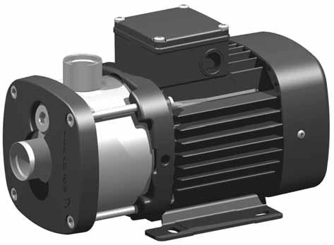
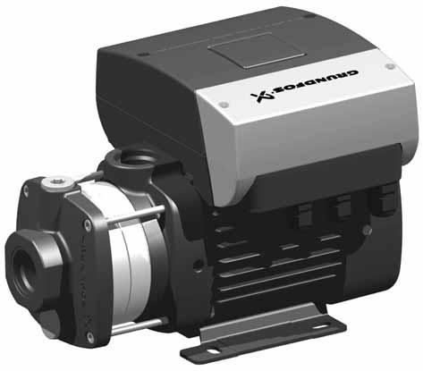
4 English (GB) 2. Type identification This section shows the nameplate, the type key and the codes that can appear in the variant code. 2.1 Nameplate As codes can be combined, a code position may contain more than one code (letter). Type Model Env IP bar PSI C F TAmb C F Insulation class Pmax 2 Tliq,max MPa 50 Hz Q nom H nom H max m³/h m m GPM PSI PSI 60 Hz Q nom H nom H max m³/h m m GPM PSI PSI TM Fig. 1 Pump nameplate 50 Hz 1 ~ 2 / 2 V 60 Hz 1 ~ 2 / 2 V I max 3 / 3 A I max 3 / 3 A I 1/1 4 / 4 A I 1/1 4 / 4 A P2 5 kw 5 HP P2 5 kw 5 HP Capacitor 6 uf / V Capacitor 6 uf / V TM Fig. 2 Motor nameplate The pump and motor nameplates are positioned on the motor fan cover or terminal box. The data and information on the pump nameplate are described in the table below. Pos. Description 1 Pump type 2 Pump model Environmental rating for enclosures based on NEMA 3 type designations 4 Enclosure class 5 Maximum ambient temperature [ C] / [ F] 6 Maximum system pressure [bar] / [psi] / [MPa] 7 Maximum liquid temperature [ C] / [ F] 8 Insulation class 9 Motor protection 10 Rated flow [m 3 /h] / [GPM] 11 Head at rated flow [m] / [psi] 12 Maximum head [m] / [psi] The data and information on the motor nameplate are described in the table below. Pos. Description 1 Number of phases 2 Voltage [V] 3 Maximum current [A] 4 Rated current [A] 5 Power output [kw] / [hp] 6 Single-phase pumps only: Capacitor size [ F] and voltage [V] 4
5 2.2 Type key CM, CME Example CME 10-8 A - R - A - E - A V B E X - X - X - X Type range Sensor CM Centrifugal Modular Sensor designation CME: CM with integrated frequency converter Mains plug Rated flow rate A: Cable glands Rated flow rate at 50 Hz [m 3 /h] B: Harting plug Number of impellers C: With cable English (GB) Pump version Motor information A: Basic version A: Standard motor (IP55) B: Oversize motor (one flange size larger) B: Phase-insulated motor for use with frequency converter E: Pumps with certificates and other approvals C: IP54 HS: High-pressure pump with high-speed MGE motor D: Pt100 in stator I: Altered pressure class E: Angular contact bearing J: Pump with a different maximum speed F: Motor heater M: Magnet-driven pump G: Three-phase motor with overload protection N: CME pump with sensor (see code for "Sensor") H: Single-phase motor with no overload protection P: Undersize motor (one flange size smaller) T: Oversize motor (two flange sizes larger) Supply voltage V: CME pump for Multi-E A: 1 x 220 V, 60 Hz X: Special pump B: 1 x 115/230 V, 60 Hz C: 1 x V, 50 Hz Pipe connection D: 1 x 127 V, 60 Hz C: Tri-Clamp E: 3 x / V, 60 Hz F: DIN flange F: 3 x / V, 50 Hz G: ANSI flange G: 3 x 200/346 V, 50 Hz; / V, 60 Hz J: JIS flange H: 3 x 575 V, 60 Hz P: PJE coupling I: 3 x 400 V, 50/60 Hz R: Whitworth thread Rp (ISO 7/1) J: 3 x V, 50 Hz; V, 60 Hz S: Internal NPT thread K: 1 x V, MGE motor L: 3 x V, MGE motor Materials in contact with pumped liquid M: 1 x V, MLE motor A: G: Inlet and discharge parts EN-GJL-200 N: 3 x V, MLE motor Pump shaft EN /AISI 431 O: Impellers/chambers EN /AISI x / V, 50 Hz 3 x / V, 60 Hz Sleeve EN /AISI 316 Material of secondary seal Pump shaft EN /AISI 316 E: EPDM (ethylene propylene) Impellers/chambers EN /AISI 316 K: FFKM (perfluor) Sleeve EN /AISI 304 V: FKM (fluor) I: Pump shaft EN /AISI 304 Impellers/chambers EN /AISI 304 Material of stationary shaft seal part X: Special version B: Carbon, synthetic resin-impregnated Q: Silicon carbide (SIC) Rubber parts in pump (excl. neck ring and shaft seal) E: EPDM (ethylene propylene) Material of rotating seal face K: FFKM (perfluor) Q: Silicon carbide (SIC) V: FKM (fluor) V: Aluminium oxide (AI203) : Gaskets between chambers of cast-iron versions are made of Tesnit BA-U. Shaft seal type designation A: O-ring seal with fixed driver The type key cannot be used for ordering, as not all combinations are possible. 5
6 English (GB) 3. Tightening torques and lubricants Pos. Designation Quantity Dimensions Torque [Nm] Lubricant 2b Screw, CM 1, 3, 5 2 M8 x THREAD-EZE Hexagon socket head cap screw CM 10, 15, 25 2 M8 x THREAD-EZE 11 O-ring x Plug Staybolt, CM 1, 3, 5, cast iron 4 M Staybolt, CM 1, 3, 5, stainless steel 4 M Staybolt, CM 10, 15, 25, cast iron 4 M THREAD-EZE Staybolt, CM 10, 15, 25, stainless steel 4 M g Screw 4 M6 x THREAD-EZE 31 O-ring, CM 1, 3, x Rocol 22 O-ring, CM 10, 15, x Rocol Lock nut 1 M O-ring x V Seal faces Silicone oil, 350 cst, food grade 107 O-ring x Rocol 22 2 M4 x Screw 4 M5 x Bearing cover plate Rocol 22 Gasket, MG 71, MG / x a Gasket, MG / Gasket, MG a O-ring x Rocol 22 O-ring, MG 71, MG x O-ring, MG 90, MG x Rocol 22 O-ring, MG 112, x a Seal ring Castrol LMX grease 181 Screw, MG 71, MG 80 4 M6 x Staybolt, MG 90 4 M5 x 220 Staybolt, MG 90L 4 M5 x 260 Staybolt, MG M5 x 270 Staybolt, MG M6 x THREAD-EZE THREAD-EZE, part number 00SV9997 (0.5 l). Rocol 22, part number 00RM2924 (1 kg). Castrol LMX grease, part number 00RM4311. Silicone oil, 350 cst, food grade 00SV0862 (1 l). 6

7 4. Service tools A B C D English (GB) E F G H I J K L M N 4.1 Standard tools Pos. Designation For pos. Further information Part number A Screwdriver 103, SV0803 B Cross-head screwdriver 181 Ph2 x 100 SV0279 C Torx screwdriver J TX30 x 115 mm SV0335 D Ring/open-end spanner 64c 15 mm mm SV0055 E Hexagon key 26 5 mm - 6 mm SV0196 F Puller for bearing 153, G Plastic hammer SV0349 H Ratchet handle M6-5 mm SV I Hexagon head driver M8-6 mm SV M5-4 mm - J Bits kit 28g, 152, SV Torque tools Pos. Designation For pos. Further information Part number K Torque screwdriver J 1-6 Nm SV0438 L Ring insert tool N 13 mm - 9 x 12 mm SV0294 M Ratchet insert tool I 9 x 12 mm - 1/2" SV0295 N Torque wrench L, M 9 x 12 mm Nm SV x12 mm Nm SV0269 7
8 English (GB) 5. Dismantling and assembly 5.1 General information If it is necessary to dismantle the pump, either because it is choked or damaged, please follow the instructions in the following sections. Position numbers of parts (digits) refer to section 7. Drawings; position numbers of tools (letters) refer to section 4. Service tools. Before dismantling the pump Disconnect the electricity supply to the motor. Close the isolating valves, if fitted, to avoid draining the system. Remove the electric cable in accordance with local regulations. Before assembly Clean and check all parts. Replace defective parts by new parts. Order the necessary service kits. Gaskets and O-rings should always be replaced when the pump is overhauled. During assembly Lubricate and tighten screws and nuts to correct torque. See section 3. Tightening torques and lubricants Assembly 1. Fit O-ring (pos. 102) on the stationary shaft seal part. See fig. 4. For correct lubricant, see section 3. Tightening torques and lubricants. Fig. 4 Assembly of MG 71 and MG 80, see section Assembly of MG 90 and MG 100, see section Fitting the O-ring on the stationary shaft seal part 2. Press the stationary shaft seal part home. See fig. 5. Warning Do not touch the seal face. TM CM 1, 3, 5, cast iron Dismantling 1. Remove staybolts (pos. 26). 2. Remove inlet part (pos. 6). 3. Remove gasket (pos. 139b) and chamber (pos. 4e). 4. Hold clamp (pos. 64c), and remove nut (pos. 67). 5. Remove lock washers (pos. 66) and clamp (pos. 64c). 6. Remove impeller (pos. 49). 7. Remove bearing ring (pos. 47a) and short spacing pipe (pos. 64a). 8. Remove chamber for bearing (pos. 4a), gasket (pos. 139b), impeller (pos. 49) and spacing pipe (pos. 64). Step 7 applies only to pumps with eight stages. Step 8 applies only to pumps with eight stages. 9. Continue the dismantling until shaft seal (pos. 105). 10.Remove shaft seal (pos. 105). See fig. 3. Fig. 5 Fitting the stationary shaft seal part (only SiC/SiC) 3. Fit the rotating shaft seal part (pos. 104) so that the seal face touches the stationary part. Warning Do not touch the seal face. 4. Fit O-ring (pos. 107) into the rotating shaft seal part (pos. 104). For correct lubricant, see section 3. Tightening torques and lubricants. 5. Fit retainer (pos. 111) and stop ring (pos. 111a). See fig. 6. TM Fig. 3 Exploded view of shaft seal TM TM Dismantling of MG 71 and MG 80, see section Dismantling of MG 90 and MG 100, see section Fig. 6 Fitting the stop ring It is advisable always to replace wear rings (pos. 45) and wear ring retainers (pos. 65). See section
9 6. Fit spring (pos. 108) and driver (pos. 112). See fig Remove O-ring (pos. 31) and cover plate (pos. 32). Fig. 7 Fitting the spring and driver 7. Fit impeller (pos. 49), spacing pipe (pos. 64), gasket (pos. 139b) and chamber plate (pos. 4f). 8. Continue the assembly until chamber for bearing (pos. 4a). Step 8 applies only to pumps with eight stages. 9. Fit chamber for bearing (pos. 4a), short spacing pipe (pos. 64a), gasket (pos. 139b) and bearing ring (pos. 47a). See section 8. Order of assembly for chambers and impellers. TM Assembly Dismantling of MG 71 and MG 80, see section Dismantling of MG 90 and MG 100, see section It is advisable always to replace wear rings (pos. 45) and wear ring retainers (pos. 65). See section 5.8. Assembly of MG 71 and MG 80, see section Assembly of MG 90 and MG 100, see section Fit cover plate (pos. 32) and O-ring (pos. 31). Lubricate the O-ring. See section 3. Tightening torques and lubricants. 2. Fit O-ring (pos. 102) on the stationary shaft seal part. See fig. 10. See section 3. Tightening torques and lubricants. English (GB) Step 9 applies only to pumps with eight stages. 10.Fit impeller (pos. 49), clamp (pos. 64c), washers (pos. 66) and nut (pos. 67). See fig. 8. TM Fig. 10 Fitting the O-ring on the stationary shaft seal part TM Fig. 8 Correct fitting of washers 11.Hold clamp (pos. 64c), and tighten nut (pos. 67). See section 3. Tightening torques and lubricants. 12.Fit chamber (pos. 4e) and gasket (pos. 139b). 13.Fit inlet part (pos. 6). 14.Fit and cross-tighten staybolts (pos. 26). See section 3. Tightening torques and lubricants. 5.3 CM 1, 3, 5, stainless steel Dismantling 1. Remove staybolts (pos. 26). 2. Remove clamping flange (pos. 6a) and sleeve (pos. 16). 3. Remove chamber (pos. 4e). 4. Hold clamp (pos. 64c), and remove nut (pos. 67). 5. Remove lock washers (pos. 66) and clamp (pos. 64c). 6. Remove impeller (pos. 49). 7. Remove bearing ring (pos. 47a) and short spacing pipe (pos. 64a). Step 7 applies only to pumps with eight or more stages. 8. Remove chamber for bearing (pos. 4a), impeller (pos. 49) and spacing pipe (pos. 64). Step 8 applies only to pumps with eight or more stages. 9. Continue the dismantling until shaft seal (pos. 105). 10.Remove shaft seal (pos. 105). See fig. 9. TM Fig. 9 Exploded view of shaft seal 9
10 English (GB) 3. Press the stationary shaft seal part home. See fig. 11. Warning Do not touch the seal face. 11.Fit impeller (pos. 49), clamp (pos. 64c), washers (pos. 66) and nut (pos. 67). See fig. 14. TM Fig. 11 Fitting the stationary shaft seal part (only SiC/SiC) 4. Fit the rotating shaft seal part (pos. 104) so that the seal face touches the stationary part. Warning Do not touch the seal face. 5. Fit O-ring (pos. 107) into the rotating shaft seal part (pos. 104). See section 3. Tightening torques and lubricants. 6. Fit retainer (pos. 111) and stop ring (pos. 111a). See fig. 12. TM Fig. 14 Correct fitting of washers 12.Hold clamp (pos. 64c), and tighten nut (pos. 67). See section 3. Tightening torques and lubricants. 13.Fit chamber (pos. 4e), sleeve (pos. 16) and clamping flange (pos. 6a). Caution Do not forget to fit the last chamber (pos. 4e), as it is possible to assemble the pump without the last chamber. 14.Fit and cross-tighten staybolts (pos. 26). See section 3. Tightening torques and lubricants. 5.4 CM 10, 15, 25, cast iron Dismantling 1. Remove staybolts (pos. 26). 2. Remove inlet part (pos. 6) and gasket (pos. 139b). 3. Hold clamp (pos. 64c), and remove nut (pos. 67). 4. Remove lock washers (pos. 66) and clamp (pos. 64c). 5. Remove impeller (pos. 49) and spacing pipe (pos. 64). 6. Remove chamber (pos. 4). 7. Continue the dismantling until shaft seal (pos. 105). 8. Remove shaft seal (pos. 105). See fig. 15. Fig. 12 Fitting the stop ring 7. Fit spring (pos. 108) and driver (pos. 112). See fig. 13. TM Fig. 15 Exploded view of shaft seal 9. Loosen and remove screws (pos. 2b) and discharge part (pos. 2). TM TM Dismantling of MG 71 and MG 80, see section Dismantling of MG 90, MG 100, MG 112 and MG 132, see section Fig. 13 Fitting the spring and driver 8. Fit impeller (pos. 49), chamber with holes (pos. 4d) and spacing pipe (pos. 64). 9. Fit impeller (pos. 49), chamber (pos. 4) and spacing pipe (pos. 64). 10.Fit impeller (pos. 49), chamber (pos. 4a), short spacing pipe (pos. 64a) and bearing ring (pos. 47a). See section 8. Order of assembly for chambers and impellers. It is advisable always to replace wear rings (pos. 45) and wear ring retainers (pos. 65). See section 5.8. Step 10 applies only to pumps with eight or more stages. 10
11 5.4.2 Assembly 8. Fit spring (pos. 108) and driver (pos. 112). See fig. 19. Assembly of MG 71 and MG 80, see section Assembly of MG 90, MG 100, MG 112 and MG 132, see section Fit discharge part (pos. 2). 2. Fit and tighten screws (pos. 2b). See section 3. Tightening torques and lubricants 3. Fit O-ring (pos. 102) on the stationary shaft seal part. See fig. 16. See section 3. Tightening torques and lubricants. Fig. 19 Fitting the spring and driver TM English (GB) Fig. 16 Fitting the O-ring on the stationary shaft seal part 4. Press the stationary shaft seal part home. See fig. 17. TM Fit short spacing pipe (pos. 64a), impeller (pos. 49), gasket (pos. 139c) and chamber (pos. 4g). 10.Fit gasket (pos. 139b), spacing pipe (pos. 64), impeller (pos. 49) and chamber (pos. 4). 11.Continue the assembly until clamp (pos. 64c). For correct fitting of chambers and impellers, see section 8. Order of assembly for chambers and impellers. 12.Fit impeller (pos. 49), clamp (pos. 64c), washers (pos. 66) and nut (pos. 67). See fig. 20. Warning Do not touch the seal face. Fig. 17 Fitting the stationary shaft seal part (only SiC/SiC) TM Fig. 20 Correct fitting of washers 13.Hold clamp (pos. 64c), and tighten nut (pos. 67). See section 3. Tightening torques and lubricants. 14.Fit gasket (pos. 139b). 15.Fit inlet part (pos. 6). 16.Fit and cross-tighten staybolts (pos. 26). See section 3. Tightening torques and lubricants. TM Fit the rotating shaft seal part (pos. 104) so that the seal face touches the stationary part. Warning Do not touch the seal face. 6. Fit O-ring (pos. 107) into the rotating shaft seal part (pos. 104). See section 3. Tightening torques and lubricants 7. Fit retainer (pos. 111) and stop ring (pos. 111a). See fig. 18. TM Fig. 18 Fitting the stop ring 11
12 English (GB) 5.5 CM 10, 15, 25, stainless steel Dismantling 1. Remove staybolts (pos. 26). 2. Remove clamping flange (pos. 6a) and sleeve (pos. 16). 3. Remove the chamber plate (pos. 4f). 4. Hold clamp (pos. 64c), and remove nut (pos. 67). 5. Remove lock washers (pos. 66) and clamp (pos. 64c). 6. Remove impeller (pos. 49). 7. Remove spacing pipe (pos. 64e), bearing ring (pos. 47a) and chamber for bearing (pos. 4a). 3. Press the stationary shaft seal part home. See fig. 23. Warning Do not touch the seal face. Step 7 applies only to pumps with six or more stages. 8. Continue the dismantling until shaft seal (pos. 105). 9. Remove shaft seal (pos. 105). See fig. 21. Fig. 23 Fitting the stationary shaft seal part (only SiC/SiC) TM Fig. 21 Exploded view of shaft seal 10.Remove O-ring (pos. 31) and cover plate (pos. 32). Dismantling of MG 71 and MG 80, see section Dismantling of MG 90, MG 100, MG 112 and MG 132, see section TM Fit the rotating shaft seal part (pos. 104) so that the seal face touches the stationary part. Warning Do not touch the seal face. 5. Fit O-ring (pos. 107) into the rotating shaft seal part (pos. 104). For correct lubricant, see section 3. Tightening torques and lubricants 6. Fit retainer (pos. 111) and stop ring (pos. 111a). See fig Assembly It is advisable always to replace wear rings (pos. 45) and wear ring retainers (pos. 65). See section 5.8. Assembly of MG 71 and MG 80, see section Assembly of MG 90, MG 100, MG 112 and MG 132, see section Fit cover plate (pos. 32) and O-ring (pos. 31). Lubricate the O-ring. See section 3. Tightening torques and lubricants. 2. Fit O-ring (pos. 102) on the stationary shaft seal part. See fig. 22. For correct lubricant, see section 3. Tightening torques and lubricants Fig. 24 Fitting the stop ring 7. Fit spring (pos. 108) and driver (pos. 112). See fig. 25. TM Fig. 22 Fitting the O-ring on the stationary shaft seal part TM Fig. 25 Fitting the spring and driver 8. Fit short spacing pipe (pos. 64a), chamber with holes (pos. 4d) and impeller (pos. 49). 9. Continue the assembly until clamp (pos. 64c). For correct fitting of chambers and impellers, see section 8. Order of assembly for chambers and impellers. TM
13 10.Fit clamp (pos. 64c), washers (pos. 66) and nut (pos. 67). See fig. 26. Fig. 26 Correct fitting of washers 11.Hold clamp (pos. 64c), and tighten nut (pos. 67). See section 3. Tightening torques and lubricants. 12.Fit the chamber plate (pos. 4f). Caution Do not forget to fit the chamber plate (pos. 4f), as it is possible to assemble the pump without the last chamber. 13.Fit sleeve (pos. 16) and clamping flange (pos. 6a). 14.Fit and cross-tighten staybolts (pos. 26). See section 3. Tightening torques and lubricants. 5.6 MG 71 and MG 80 motors Dismantling 1. Remove screws (pos. 152). 2. Remove fan cover (pos. 151). 3. Remove fan (pos. 156) and seal ring (pos. 159a). 4. Remove screws (pos. 181). 5. Remove motor flange (pos. 156b) and gasket (pos. 157a). 6. Remove diverting disc (pos. 79), O-ring (pos. 158a) and bearing cover plate (pos. 155). 7. Pull shaft (pos. 51) out of stator housing (pos. 150). 8. Pull bearing (pos. 153) off shaft (pos. 51). 9. Remove O-ring (pos. 159) and spring (pos. 158). 10.Pull bearing (pos. 154) off shaft (pos. 51) Assembly 1. Push bearing (pos. 154) onto shaft (pos. 51). 2. Fit spring (pos. 158) and O-ring (pos. 159). See fig. 27. Fig. 27 Correct fitting of spring and O-ring 3. Push bearing (pos. 153) onto shaft (pos. 51). 4. Fit shaft (pos. 51) into stator housing (pos. 150). 5. Fit bearing cover plate (pos. 155), O-ring (pos. 158a) and diverting disc (pos. 79). Lubricate the surface of the cover plate (pos. 155) turning against the bearing. Lubricate the O-ring (pos. 158a). For correct lubricant, see section 3. Tightening torques and lubricants. 6. Fit gasket (pos. 157a) and motor flange (pos. 156b). 7. Fit and cross-tighten screws (pos. 181). See section 3. Tightening torques and lubricants. 8. Fit and lubricate the seal ring (pos. 159a). For correct lubricant, see section 3. Tightening torques and lubricants. 9. Fit the fan (pos. 156). 10.Fit fan cover (pos. 151). 11.Fit and tighten screws (pos. 152). See section 3. Tightening torques and lubricants. TM TM MG 90, MG 100, MG 112 and MG 132 motors Dismantling 1. Only cast iron pumps: Remove screws (pos. 2b). 2. Only cast iron pumps: Remove discharge part (pos. 2). 3. Remove screws (pos. 152). 4. Remove fan cover (pos. 151). 5. Remove fan (pos. 156) and seal ring (pos. 159a). 6. Remove staybolts (pos. 181). 7. Remove motor flange (pos. 156b), gasket (pos. 157a) and bearing cover (pos. 156a). 8. Remove diverting disc (pos. 79), O-ring (pos. 158a) and bearing cover plate (pos. 155). 9. Pull shaft (pos. 51) out of stator housing (pos. 150). 10.Pull bearing (pos. 153) off shaft (pos. 51). 11.Remove O-ring (pos. 159) and spring (pos. 158). 12.Pull bearing (pos. 154) off shaft (pos. 51) Assembly 1. Push bearing (pos. 154) onto shaft (pos. 51). 2. Fit spring (pos. 158) and O-ring (pos. 159). See fig. 28. Fig. 28 Correct fitting of spring and O-ring 3. Push bearing (pos. 153) onto shaft (pos. 51). 4. Fit shaft (pos. 51) into stator housing (pos. 150). 5. Fit bearing cover plate (pos. 155), O-ring (pos. 158a) and diverting disc (pos. 79). Lubricate the surface of the cover plate (pos. 155) turning against the bearing. Lubricate the O-ring (pos. 158a). For correct lubricant, see section 3. Tightening torques and lubricants. 6. Fit bearing cover (pos. 156a), gasket (pos. 157a) and motor flange (pos. 156b). 7. Fit and cross-tighten staybolts (pos. 181). See section 3. Tightening torques and lubricants. 8. Fit and lubricate the seal ring (pos. 159a). For correct lubricant, see section 3. Tightening torques and lubricants. 9. Fit the fan (pos. 156). 10.Fit fan cover (pos. 151). 11.Fit and tighten screws (pos. 152). See section 3. Tightening torques and lubricants. 12.Only cast iron pumps: Fit discharge part (pos. 2). 13.Only cast iron pumps: Fit and tighten screws (pos. 2b). See section 3. Tightening torques and lubricants. TM English (GB) 13
14 English (GB) 5.8 Checking and replacing impellers and chambers Check Impeller Check whether it is necessary to replace the impeller due to friction between wear ring and impeller skirt. If wear has caused a noticeable (use a finger nail) groove in the impeller skirt, the impeller should be replaced. It is advisable always to replace wear rings (pos. 45) and wear ring retainers (pos. 65) when the chamber stack is dismantled. Check whether there is a visible and noticeable (use a finger nail) edge on the rotating bearing ring. Replace Wear ring/wear ring retainer 1. Prise the wear ring retainer (pos. 65) up and free of the chamber using a screwdriver. 2. Remove wear ring (pos. 45). 3. Fit a new wear ring in the chamber. See fig Press a new wear ring retainer on the wear ring and into the chamber. It must be possible to move the wear ring freely (sideways) between the retainer and the chamber. Bearing ring Replace both bearing rings (pos. 47a) and chamber for bearing (pos. 4a). TM Fig. 29 Correct fitting of wear ring 14
15 6. Fault finding Warning Before removing the terminal box cover, make sure that the electricity supply has been switched off. The pumped liquid may be scalding hot and under high pressure. Before any removal or dismantling of the pump, the system must therefore be drained, or the isolating valves on either side of the pump must be closed. English (GB) Fault Cause Remedy 1. The pump does not run. a) Supply failure. Switch on the switch. Check cables and cable connections for defects and loose connections. b) Fuses are blown. Check cables and cable connections for defects, and replace the fuses. c) Motor protection tripped. See 2. a), b), c), d), e), f). d) Control-current circuit defective. Repair or replace the control-current circuit. 2. Motor-protective circuit breaker has tripped (trips out immediately when supply is switched on). 3. The motor-protective circuit breaker trips out occasionally. 4. The motor-protective circuit breaker has not tripped out, but the pump is inadvertently out of operation. a) Fuses are blown. See 1. b). b) Contacts of the motor-protective circuit breaker or magnet coil defective. Replace the contacts of the motor-protective circuit breaker, the magnet coil or the entire motor-protective circuit breaker. c) Cable connection is loose or faulty. Check cables and cable connections for defects, and replace the fuses. d) Motor winding is defective. Repair or replace the motor. e) The pump is mechanically blocked. Switch off the electricity supply, and clean or repair the pump. f) The setting of the motor-protective circuit breaker is too low. Set the motor-protective circuit breaker according to the rated current of the motor (I 1/1 ). See nameplate. a) The setting of the motor-protective circuit breaker is too low. See 2. f). b) Periodic supply failure. See 2. c). c) Periodically low voltage. Check cables and cable connections for defects and loose connections. Check that the supply cable of the pump is correctly sized. a) See 1. a), b), d) and 2. e). 5. The pump performance is unstable. a) Pump inlet pressure too low. Check the inlet conditions of the pump. b) Inlet pipe is partly blocked by impurities. Remove and clean the inlet pipe. c) Leakage in inlet pipe. Remove and repair the inlet pipe. d) Air in inlet pipe or pump. Vent the inlet pipe/pump. Check the inlet conditions of the pump. 6. The pump runs, but gives no water. a) Pump inlet pressure too low. See 5. a). b) Inlet pipe partly blocked by impurities. See 5. b). c) The foot or non-return valve is stuck in its closed position. Remove and clean, repair or replace the valve. d) Leakage in inlet pipe. See 5. c). e) Air in inlet pipe or pump. See 5. d). 7. The pump runs backwards when a) Leakage in inlet pipe. See 5. c). switched off. b) Foot or non-return valve defective. See 6. c). c) The foot valve is stuck in completely or partly open position. See 6. c). 8. The pump runs with reduced performance. a) Wrong direction of rotation. Three-phase pumps only: Switch off the electricity supply with the external circuit breaker and interchange two phases in the pump terminal box. It is possible to check the direction of rotation by means of the installation indicator. Black: The direction of rotation is correct. White: The direction of rotation is incorrect. b) See 5. a), b), c), d). 15
16 English (GB) 7. Drawings 7.1 CM 1, 3, 5 TM Fig. 30 CM 1, 3, 5, stainless steel 16
17 TM English (GB) Fig. 31 CM 1, 3, 5, cast iron 17
18 English (GB) 7.2 CM 10, 15, 25 TM Fig. 32 CM 10, 15, 25, stainless steel 18
19 TM English (GB) Fig. 33 CM 10, 15, 25, cast iron 19
20 English (GB) 8. Order of assembly for chambers and impellers 8.1 Key for CM 1, 3, 5 Bearings Chamber cpl. A Chamber with bearing cpl. B Chamber with holes C Chamber plate D Chamber without guide vanes E Impeller F 8.2 CM 1, 3, 5, cast iron CM 1, 3, 5, cast iron Pos Chamber Impeller Chamber Impeller Chamber Impeller Chamber Impeller Chamber Impeller Chamber Impeller Chamber Impeller 1* D F D F D F D F D F D F D F 2 E F A F A F A F A F A F A F 3 E F A F A F A F A F A F 4 E F A F A F A F A F 5 E F A F A F A F 6 E F A F A F 7 E F B F 8 E F * Pos. 1 is next to the motor. 8.3 CM 1, 3, 5, stainless steel CM 1, 3, 5, stainless steel Pos Chamber Impeller Chamber Impeller Chamber Impeller Chamber Impeller Chamber Impeller Chamber Impeller Chamber Impeller 1* C F C F C F C F C F C F C F 2 E F A F A F A F A F A F A F 3 E E F A F A F A F A F A F 4 E F A F A F A F A F 5 E F A F A F A F 6 E F A F A F 7 E E F B F 8 E F 9 E * Pos. 1 is next to the motor. 20
21 CM 1, 3, 5, stainless steel Pos Chamber Impeller Chamber Impeller Chamber Impeller Chamber Impeller Chamber Impeller Chamber Impeller 1* C F C F C F C F C F C F 2 A F A F A F A F A F A F 3 A F A F A F A F A F A F 4 A F A F A F A F A F A F 5 A F A F A F A F A F A F 6 A F A F A F A F A F A F 7 A F A F A F A F A F A F 8 B F A F A F A F A F A F 9 E F B F A F A F A F A F 10 E F B F A F A F A F 11 E E F B F B F B F 12 E F A F A F 13 E E F A F 14 E E E F * Pos. 1 is next to the motor. English (GB) 8.4 Key for CM 10, 15, 25 Bearings Chamber cpl. Chamber with bearing cpl. Chamber with holes Impeller located in cast iron component Chamber without sand lift Chamber plate, SS pumps Chamber without guide vanes Chamber without guide vanes and sand lift Impeller A B C D E F G H I 8.5 CM 10, 15, 25, cast iron CM 10, 15, 25, cast iron Pos Chamber Impeller Chamber Impeller Chamber Impeller Chamber Impeller Chamber Impeller 1* D I D I D I D I D I 2 H E I E I E I E I 3 A I A I A I 4 A I A I 5 A I * Pos. 1 is next to the motor. 21
22 English (GB) 8.6 CM 10, 15, 25, stainless steel CM 10, 15, 25, stainless steel Pos Chamber Impeller Chamber Impeller Chamber Impeller Chamber Impeller Chamber Impeller 1* C I C I C I C I C I 2 G A I A I A I A I 3 G G A I A I A I 4 F F F A I A I 5 F A I 6 G 7 F * Pos. 1 is next to the motor. CM 10, 15, 25, stainless steel Pos Chamber Impeller Chamber Impeller Chamber Impeller 1* C I C I C I 2 A I A I A I 3 A I A I A I 4 A I A I A I 5 A I A I A I 6 B I A I A I 7 F B I A I 8 G B I 9 F F * Pos 1 is next to the motor. Subject to alterations. 22
23 Argentina Bombas GRUNDFOS de Argentina S.A. Ruta Panamericana km Lote 34A Garin Pcia. de Buenos Aires Phone: Telefax: Australia GRUNDFOS Pumps Pty. Ltd. P.O. Box 2040 Regency Park South Australia 5942 Phone: Telefax: Austria GRUNDFOS Pumpen Vertrieb Ges.m.b.H. Grundfosstraße 2 A-5082 Grödig/Salzburg Tel.: Telefax: Belgium N.V. GRUNDFOS Bellux S.A. Boomsesteenweg B-2630 Aartselaar Tél.: Télécopie: Belorussia Представительство ГРУНДФОС в Минске , Минск, ул. В. Хоружей, 22, оф Тел.: +(37517) , Факс: +(37517) grundfos_minsk@mail.ru Bosnia/Herzegovina GRUNDFOS Sarajevo Trg Heroja 16, BiH Sarajevo Phone: Telefax: grundfos@bih.net.ba Brazil BOMBAS GRUNDFOS DO BRASIL Av. Humberto de Alencar Castelo Branco, 630 CEP São Bernardo do Campo - SP Phone: Telefax: Bulgaria Grundfos Bulgaria EOOD Slatina District Iztochna Tangenta street no. 100 BG Sofia Tel Fax bulgaria@grundfos.bg Canada GRUNDFOS Canada Inc Brighton Road Oakville, Ontario L6H 6C9 Phone: Telefax: China GRUNDFOS Pumps (Shanghai) Co. Ltd. 50/F Maxdo Center No. 8 XingYi Rd. Hongqiao development Zone Shanghai PRC Phone: Telefax: Croatia GRUNDFOS CROATIA d.o.o. Cebini 37, Buzin HR Zagreb Phone: Telefax: Czech Republic GRUNDFOS s.r.o. Čajkovského Olomouc Phone: Telefax: Denmark GRUNDFOS DK A/S Martin Bachs Vej 3 DK-8850 Bjerringbro Tlf.: Telefax: info_gdk@grundfos.com Estonia GRUNDFOS Pumps Eesti OÜ Peterburi tee 92G Tallinn Tel: Fax: Finland OY GRUNDFOS Pumput AB Mestarintie 11 FIN Vantaa Phone: Telefax: France Pompes GRUNDFOS Distribution S.A. Parc d Activités de Chesnes 57, rue de Malacombe F St. Quentin Fallavier (Lyon) Tél.: Télécopie: Germany GRUNDFOS GMBH Schlüterstr Erkrath Tel.: +49-(0) Telefax: +49-(0) infoservice@grundfos.de Service in Deutschland: kundendienst@grundfos.de Greece GRUNDFOS Hellas A.E.B.E. 20th km. Athinon-Markopoulou Av. P.O. Box 71 GR Peania Phone: Telefax: Hong Kong GRUNDFOS Pumps (Hong Kong) Ltd. Unit 1, Ground floor Siu Wai Industrial Centre Wing Hong Street & 68 King Lam Street, Cheung Sha Wan Kowloon Phone: / Telefax: Hungary GRUNDFOS Hungária Kft. Park u. 8 H-2045 Törökbálint, Phone: Telefax: India GRUNDFOS Pumps India Private Limited 118 Old Mahabalipuram Road Thoraipakkam Chennai Phone: Indonesia PT GRUNDFOS Pompa Jl. Rawa Sumur III, Blok III / CC-1 Kawasan Industri, Pulogadung Jakarta Phone: Telefax: / Ireland GRUNDFOS (Ireland) Ltd. Unit A, Merrywell Business Park Ballymount Road Lower Dublin 12 Phone: Telefax: Italy GRUNDFOS Pompe Italia S.r.l. Via Gran Sasso 4 I Truccazzano (Milano) Tel.: Telefax: / Japan GRUNDFOS Pumps K.K. Gotanda Metalion Bldg., 5F, , Higashi-gotanda Shiagawa-ku, Tokyo Japan Phone: Telefax: Korea GRUNDFOS Pumps Korea Ltd. 6th Floor, Aju Building Yeoksam-dong, Kangnam-ku, Seoul, Korea Phone: Telefax: Latvia SIA GRUNDFOS Pumps Latvia Deglava biznesa centrs Augusta Deglava ielā 60, LV-1035, Rīga, Tālr.: , Fakss: Lithuania GRUNDFOS Pumps UAB Smolensko g. 6 LT Vilnius Tel: Fax: Malaysia GRUNDFOS Pumps Sdn. Bhd. 7 Jalan Peguam U1/25 Glenmarie Industrial Park Shah Alam Selangor Phone: Telefax: México Bombas GRUNDFOS de México S.A. de C.V. Boulevard TLC No. 15 Parque Industrial Stiva Aeropuerto Apodaca, N.L Phone: Telefax: Netherlands GRUNDFOS Netherlands Veluwezoom AE Almere Postbus CA ALMERE Tel.: Telefax: info_gnl@grundfos.com New Zealand GRUNDFOS Pumps NZ Ltd. 17 Beatrice Tinsley Crescent North Harbour Industrial Estate Albany, Auckland Phone: Telefax: Norway GRUNDFOS Pumper A/S Strømsveien 344 Postboks 235, Leirdal N-1011 Oslo Tlf.: Telefax: Poland GRUNDFOS Pompy Sp. z o.o. ul. Klonowa 23 Baranowo k. Poznania PL Przeźmierowo Tel: (+48-61) Fax: (+48-61) Portugal Bombas GRUNDFOS Portugal, S.A. Rua Calvet de Magalhães, 241 Apartado 1079 P Paço de Arcos Tel.: Telefax: România GRUNDFOS Pompe România SRL Bd. Biruintei, nr 103 Pantelimon county Ilfov Phone: Telefax: romania@grundfos.ro Russia ООО Грундфос Россия, Москва, ул. Школьная 39 Тел. (+7) , Факс (+7) , grundfos.moscow@grundfos.com Serbia GRUNDFOS Predstavništvo Beograd Dr. Milutina Ivkovića 2a/29 YU Beograd Phone: / Telefax: Singapore GRUNDFOS (Singapore) Pte. Ltd. 24 Tuas West Road Jurong Town Singapore Phone: Telefax: Slovenia GRUNDFOS d.o.o. Šlandrova 8b, SI-1231 Ljubljana-Črnuče Phone: Telefax: slovenia@grundfos.si South Africa GRUNDFOS (PTY) LTD Corner Mountjoy and George Allen Roads Wilbart Ext. 2 Bedfordview 2008 Phone: (+27) Fax: (+27) lsmart@grundfos.com Spain Bombas GRUNDFOS España S.A. Camino de la Fuentecilla, s/n E Algete (Madrid) Tel.: Telefax: Sweden GRUNDFOS AB Box 333 (Lunnagårdsgatan 6) Mölndal Tel.: Telefax: Switzerland GRUNDFOS Pumpen AG Bruggacherstrasse 10 CH-8117 Fällanden/ZH Tel.: Telefax: Taiwan GRUNDFOS Pumps (Taiwan) Ltd. 7 Floor, 219 Min-Chuan Road Taichung, Taiwan, R.O.C. Phone: Telefax: Thailand GRUNDFOS (Thailand) Ltd. 92 Chaloem Phrakiat Rama 9 Road, Dokmai, Pravej, Bangkok Phone: Telefax: Turkey GRUNDFOS POMPA San. ve Tic. Ltd. Sti. Gebze Organize Sanayi Bölgesi Ihsan dede Caddesi, 2. yol 200. Sokak No Gebze/ Kocaeli Phone: Telefax: satis@grundfos.com Ukraine ТОВ ГРУНДФОС УКРАЇНА Київ, Вул. Московська 8б, Тел.:( ) Фах.: ( ) ukraine@grundfos.com United Arab Emirates GRUNDFOS Gulf Distribution P.O. Box Jebel Ali Free Zone Dubai Phone: Telefax: United Kingdom GRUNDFOS Pumps Ltd. Grovebury Road Leighton Buzzard/Beds. LU7 8TL Phone: Telefax: U.S.A. GRUNDFOS Pumps Corporation West 118th Terrace Olathe, Kansas Phone: Telefax: Usbekistan Представительство ГРУНДФОС в Ташкенте Ташкент ул.усмана Носира 1-й тупик 5 Телефон: (3712) Факс: (3712) Revised Grundfos companies
24 Being responsible is our foundation Thinking ahead makes it possible Innovation is the essence GB The name Grundfos, the Grundfos logo, and the payoff Be Think Innovate are registrated trademarks owned by Grundfos Management A/S or Grundfos A/S, Denmark. All rights reserved worldwide.
GRUNDFOS ILLUSTRATED SERVICE INSTRUCTIONS. Large SP SP 17, 30, 46, 60, 77, 95, 125, 160, 215
 GRUNDFOS ILLUSTRATED SERVICE INSTRUCTIONS Large SP SP 17, 30, 46, 60, 77, 95, 125, 160, 215 Contents PAGE SP 46 and 60... 2 SP 125 and 160... 5 SP 215... 7 SP 17 and 30... 10 SP 77 and 95... 18 1 SP 46
GRUNDFOS INSTRUCTIONS MMS 6. Service instructions
 GRUNDFOS INSTRUCTIONS MMS 6 Service instructions English (GB) English (GB) Service instructions Original service instructions. CONTENTS 1. Symbols used in this document Page 1. Symbols used in this document
TP, TPD union and low head
 GRUNDFOS INSTRUCTIONS TP, TPD union and low head 50/60 Hz 1/3~ Service instructions English (GB) English (GB) Service instructions Original service instructions. CONTENTS 1. Symbols used in this document
CR, CRI, CRN 1s, 1, 3, 5, 10, 15, 20 CR, CRN 32, 45, 64, 90, 120, 150
 GRUNDFOS INSTRUCTIONS, I, N 1s, 1, 3, 5, 10, 15, 20, N 32, 45, 64, 90, 120, 150 Double seal (tandem) Installation and operating instructions 2 nglish (GB) Installation and operating instructions Original
GRUNDFOS INSTRUCTIONS SP 7/9/11/14. Service instructions
 GRUNDFOS INSTRUCTIONS SP 7/9/11/14 Service instructions English (GB) English (GB) Service instructions Original service instructions. CONTENTS Page 1. Symbols used in this document 2 2. Identification
GRUNDFOS INSTRUCTIONS. Installation and operating instructions
 GRUNDFOS INSTRUCTIONS JP Installation and operating instructions English (GB) English (GB) Installation and operating instructions Original installation and operating instructions. CONTENTS Page 1. Symbols
GRUNDFOS INSTRUCTIONS SMG. 50/60 Hz DIN/ANSI. Service instructions
 GRUNDFOS INSTRUCTIONS SMG 50/60 Hz DIN/ANSI Service instructions English (GB) English (GB) Service instructions Original service instructions. CONTENTS Page 1. Symbols used in this document 2 2. Identification
GRUNDFOS INSTRUCTIONS CR, CRI, CRN, CRT. ATEX-approved pumps Installation and operating instructions
 GRUNDFOS INSTRUCTIONS,,, T ATEX-approved pumps Installation and operating instructions Declaration of Conformity We, Grundfos, declare under our sole responsibility that the products,, and T, to which
INSTRUCTIONS DWK. Installation and operating instructions. manufactured for Grundfos
 INSTRUCTIONS DWK Installation and operating instructions manufactured for Grundfos Declaration of Conformity We, Grundfos, declare under our sole responsibility that the product DWK, to which this declaration
GRUNDFOS INSTRUCTIONS. MGE model F. Service instructions
 GRUNDFOS INSTRUCTIONS MGE model F Service instructions Preface These service instructions describe fault finding of pumps with Grundfos motors, type MGE model F (hereafter called MGE-F). The service instructions
Cranes for SMD, SMG, SFG, SRG, AMD, AMG, AFG and SRP
 GRUNDFOS INSTRUCTIONS Cranes for SMD, SMG, SFG, SRG, AMD, AMG, AFG and SRP Installation and operating instructions Installation and operating instructions Original installation and operating instructions
GRUNDFOS INSTRUCTIONS SCALA. Installation and operating instructions
 GRUNDFOS INSTRUCTIONS SCALA Installation and operating instructions English (GB) English (GB) Installation and operating instructions Original installation and operating instructions. These installation
Installation and operating instructions
 GRUNDFOS INSTRUCTIONS CM Installation and operating instructions Installation and operating instructions http://net.grundfos.com/qr/i/95121197 Quick Guide (CM) http://net.grundfos.com/qr/i/95121198 Quick
GRUNDFOS INSTRUCTIONS. UPE Series 2000 UPE(D) FZ, UPE FZ. Installation and operating instructions
 FZ, UPE FZ. Installation and operating instructions") GRUNDFOS INSTRUCTIONS UPE Series 2000 UPE(D) 80-120 FZ, UPE 100-120 FZ Installation and operating instructions UPE Series 2000 Declaration of Conformity.......................................... 4 English
GRUNDFOS INSTRUCTIONS UPE Series 2000 UPE(D) 80-120 FZ, UPE 100-120 FZ Installation and operating instructions UPE Series 2000 Declaration of Conformity.......................................... 4 English
GRUNDFOS INSTRUCTIONS NK, NKG. ATEX-approved pumps. Installation and operating instructions
 GRUNDFOS INSTRUCTIONS NK, NKG ATEX-approved pumps Installation and operating instructions NK, NKG English (GB) Installation and operating instructions...........................................................
GRUNDFOS INSTRUCTIONS MS6000. Submersible motors. Service instructions
 GRUNDFOS INSTRUCTIONS MS6000 Submersible motors Service instructions English (GB) English (GB) Service instructions Original service instructions. CONTENTS Page 1. Symbols used in this document 2 2. General
GRUNDFOS INSTRUCTIONS SCALA. Installation and operating instructions
 GRUNDFOS INSTRUCTIONS SCALA Installation and operating instructions English (GB) English (GB) Installation and operating instructions Original installation and operating instructions These installation
Service instructions. Contents. MTR 10, 15 and /60 Hz 1/3~
 Service instructions MTR 0, and 0 0/0 Hz /~ Contents. Type identification.... Nameplate.... Type key.... Code for shaft seal.... Torques and lubricants.... Service tools.... Special tools.... Standard
GRUNDFOS INSTRUCTIONS. SEG AUTO Adapt kw, DIN, 50 Hz. Service instructions
 GRUNDFOS INSTRUCTIONS SEG AUTO Adapt 0.9-4.0 kw, DIN, 50 Hz Service instructions Service instructions Original service instructions CONTENTS Page 1. Symbols used in this document 2 2. Returning the product
CRI5. Parts List & Kits. GRUNDFOS Industrial Service Manual. Contents
 GRUNDFOS Industrial Service Manual CRI5 Parts List & Kits Contents Parts List Spare Part Kits Accessories Special Tools Standard Tools Tools for Torques Exploded View CRI5 105(b) Tandem Standard Options
GRUNDFOS INSTRUCTIONS MTC. Installation and operating instructions
 GRUNDFOS INSTRUCTIONS MTC Installation and operating instructions LIMITED WARRANTY Products manufactured by GRUNDFOS PUMPS CORPORATION (Grundfos) are warranted to the original user only to be free of defects
NKS GRUNDFOS NKS. Spare parts CATALOGUE
 GRUNDFOS NKS Spare parts CATALOGUE 05/2003 Type key For units without motor the motor data are left out, and for bare shaft pumps the coupling and motor data are left out. NKS 125-100 - 200 / 190-3 - W
GRUNDFOS Commer CR1. Parts List & Kits. Contents. Parts List Spare Part Kits Accessories Special Tools Standard Tools Tools for Torques
 GRUNDFOS Commer ommercial Industrial Service Manual CR1 Parts List & Kits Contents Parts List Spare Part Kits Accessories Special Tools Standard Tools Tools for Torques 80 (STACK ) 105(b) Tandem 109(a)
CMB, CMB-SP Booster PM2
 CMB, CMB-SP Booster PM2 Supplement to Quick Guide GRUNDFOS INSTRUCTIONS English (GB) English (GB) Installation and operating instructions Supplement to quick guide. CONTENTS Page 1. Symbols used in this
SMART Digital S - DDE
 GRUNDFOS INSTRUCTIONS SMART Digital S - DDE up to 15 l/h Installation and operating instructions Further languages http://net.grundfos.com/qr/i/95725839 English (GB) English (GB) Installation and operating
CR30 CR60 (Model B) CR
 CR") GRUNDFOS CR30 CR60 (Model B) IMPELLER STACK KIT DISMANTLING AND REASSEMBLY CR30 CR60 (Model B) CR Please note...we recommend installing a new Shaft Seal & Gasket Kit along with this kit. When installing
GRUNDFOS CR30 CR60 (Model B) IMPELLER STACK KIT DISMANTLING AND REASSEMBLY CR30 CR60 (Model B) CR Please note...we recommend installing a new Shaft Seal & Gasket Kit along with this kit. When installing
DOUBLE OCTOMILL TM PRODUCT RANGE
 DOUBLE OCTOMILL TM PRODUCT RANGE Double Octomill insert selection and cutting data recommendations, see page 6. complete insert programme, see page 7. Tool angles: Jo = -11q Jp = - 8q Jf = - 8q Pitch
GRUNDFOS INSTRUCTIONS. UPS, UPSD Series 200. Installation and operating instructions. Other languages.
 GRUDFOS ISTRUCTIOS UPS, UPSD Series 200 Installation and operating instructions Other languages http://net.grundfos.com/qr/i/96459997 English (GB) English (GB) Installation and operating instructions Original
GRUNDFOS Commer CR3. Parts List & Kits. Contents. Parts List Spare Part Kits Accessories Special Tools Standard Tools Tools for Torques
 GRUNDFOS Commer ommercial Industrial Service Manual CR3 Parts List & Kits Contents Parts List Spare Part Kits Accessories Special Tools Standard Tools Tools for Torques 80 (STACK ) 105(b) Tandem 109(a)
GRUNDFOS CR SERVICE MANUAL CR5. Parts List & Kits. Contents. Parts List Spare Part Kits Accessories Special Tools Standard Tools Tools for Torques
 GRUNDFOS CR SERVICE MANUAL CR5 Parts List & Kits Contents Parts List Spare Part Kits Accessories Special Tools Standard Tools Tools for Torques 2 Exploded View CR5 Parts List & Kits CR5 Pos. Part Description
GRUNDFOS CR SERVICE MANUAL CR1. Parts List & Kits. Contents. Parts List Spare Part Kits Accessories Special Tools Standard Tools Tools for Torques
 GRUNDFOS CR SERVICE MANUAL CR1 Parts List & Kits Contents Parts List Spare Part Kits Accessories Special Tools Standard Tools Tools for Torques Exploded View CR1 2 Parts List & Kits CR1 Pos. Part Description
GRUNDFOS CR SERVICE MANUAL CR3. Parts List & Kits. Contents. Parts List Spare Part Kits Accessories Special Tools Standard Tools Tools for Torques
 GRUNDFOS CR SERVICE MANUAL CR3 Parts List & Kits Contents Parts List Spare Part Kits Accessories Special Tools Standard Tools Tools for Torques 2 Exploded View CR3 Parts List & Kits CR3 Pos. parts list
ISO Interface. Large capacity. Light weight. Accommodates enclosure IP65. Solenoid Valve (with M Connector) Conforming to ISO
 Conforming to ISO") P-EX01-A Solenoid Valve (with M Connector) Conforming to ISO 1507-1, Large capacity EVS1-01 (Size: 01) EVS1-0 (Size: 0) Light weight Size 01 (-position): 0.6kg Size 0 (-position): 0.18kg Flow rate 1000L/min
P-EX01-A Solenoid Valve (with M Connector) Conforming to ISO 1507-1, Large capacity EVS1-01 (Size: 01) EVS1-0 (Size: 0) Light weight Size 01 (-position): 0.6kg Size 0 (-position): 0.18kg Flow rate 1000L/min
AUSTRIA. Table 1. FDI flows in the host economy, by geographical origin. (Millions of US dollars)
") Table 1. FDI flows in the host economy, by geographical origin World 5 690 138 6 195 3 184 10 784 7 933 31 154 6 858 9 303 840 10 618 5 760 Developed economies 5 740 13 5 341 2 689 10 137 6 291 29 721
Table 1. FDI flows in the host economy, by geographical origin World 5 690 138 6 195 3 184 10 784 7 933 31 154 6 858 9 303 840 10 618 5 760 Developed economies 5 740 13 5 341 2 689 10 137 6 291 29 721
CRI3. Parts List & Kits. GRUNDFOS Industrial Service Manual. Contents
 GRUNDFOS Industrial Service Manual CRI3 Parts List & Kits Contents Parts List Spare Part Kits Accessories Special Tools Standard Tools Tools for Torques Exploded View CRI3 105(b) Tandem Standard Options
GRUNDFOS CR SERVICE MANUAL CRN1. Parts List & Kits. Contents. Parts List Spare Part Kits Accessories Special Tools Standard Tools Tools for Torques
 GRUNDFOS CR SERVICE MANUAL CRN1 Parts List & Kits Contents Parts List Spare Part Kits Accessories Special Tools Standard Tools Tools for Torques 105(b) Tandem Standard Options 109 (a) 113 37 146 111 104
GRUNDFOS GROUNDWATER SERVICE MANUAL 300S. Parts List Submersibles. Contents Parts List Special Tools Standard Tools Part Dimensions
 GRUNDFOS GROUNDWATER SERVICE MANUAL 300S Parts List 6 8 10 Submersibles Contents Parts List Special Tools Standard Tools Part Dimensions Exploded View 300S 1 13 11c 8a 8b 10 6b 7 13 1 2 1a 3 4 6 13 7 8
GRUNDFOS GROUNDWATER SERVICE MANUAL 230S. Parts List Submersibles. Contents Parts List Special Tools Standard Tools Part Dimensions
 GRUNDFOS GROUNDWATER SERVICE MANUAL 230S Parts List 6 8 10 Submersibles Contents Parts List Special Tools Standard Tools Part Dimensions Exploded View 230S 1 72 13 11c 8a 8b 10 6b 7 72 13 1 2 1a 3 4 6
Infographics on Electromobility (January 2019)
") Infographics on Electromobility (January 2019) Publisher: BMW Group Corporate Communications Electromobility Last Update: 04.01.2019 Contact: presse@bmw.de ELECTROMOBILITY IN GERMANY. SHARE IN NEW REGISTRATIONS
Infographics on Electromobility (January 2019) Publisher: BMW Group Corporate Communications Electromobility Last Update: 04.01.2019 Contact: presse@bmw.de ELECTROMOBILITY IN GERMANY. SHARE IN NEW REGISTRATIONS
GRUNDFOS CR SERVICE MANUAL. CRI1s. Parts List & Kits. Contents. Parts List Spare Part Kits Accessories Special Tools Standard Tools Tools for Torques
 GRUNDFOS CR SERVICE MANUAL CRI1s Parts List & Kits Contents Parts List Spare Part Kits Accessories Special Tools Standard Tools Tools for Torques Exploded View CRI1s 2 Parts List & Kits CRI1s Pos. parts
PREVIEW. Fieldbus System for Distributed I/O NEW PRODUCTS
 NEW PRODUCTS PREVIEW Fieldbus System for Distributed I/O! Dual Port EtherNet/IP TM Gateway controls up to 8 Valve Manifolds and 8 Input blocks Controls up to 128 Inputs and 128 Outputs Supports QuickConnect
Installation instructions
 www.somfy.com Sonesse 0 DCT Installation instructions Ref :505080A Please read installation instructions and programming instructions completely prior to proceeding with installation and programming. Failure
GRUNDFOS INSTRUCTIONS. SMART Digital - DDC. Installation and operating instructions
 GRUNDFOS INSTRUCTIONS SMART Digital - DDC Installation and operating instructions Declaration of conformity Declaration of conformity GB Declaration of Conformity We, Grundfos Alldos, declare under our
Max. flow capacity of 5,000 L/min and max. discharge head of 98m. The world s largest class fluoroplastic magnetic drive pump.
 MDW series Magnetic drive pumps Max. flow capacity of 5,000 L/min and max. discharge head of 98m. The world s largest class fluoroplastic magnetic drive pump. The MDW series are the largest class fluoroplastic
GRUNDFOS INSTRUCTIONS NB, NBG. Installation and operating instructions
 GRUNDFOS INSTRUCTIONS NB, NBG Installation and operating instructions English (GB) English (GB) Installation and operating instructions Original installation and operating instructions CONTENTS Page 1.
SL1.50, SLV.65. English (GB) Installation and operating instructions... 23
 Installation and operating instructions... 23") SL1.50, SLV.65 English (GB) Installation and operating instructions................................ 23 目录 3 产品合格声明书 CN 产品合格声明书我们格兰富在我们的全权责任下声明, 产品 SL1.50 和 SLV65, 即该合格证所指之产品, 符合欧共体使其成员国法律趋于一致的以下欧共理事会指令
SL1.50, SLV.65 English (GB) Installation and operating instructions................................ 23 目录 3 产品合格声明书 CN 产品合格声明书我们格兰富在我们的全权责任下声明, 产品 SL1.50 和 SLV65, 即该合格证所指之产品, 符合欧共体使其成员国法律趋于一致的以下欧共理事会指令
replacement parts 6.1 General 6.2 Ordering
 6.0 Replacement Parts 6.1 General Always provide the serial number of the unit on which the parts will be used. The serial number is stamped on the unit nameplate. 6.2 Ordering To ensure proper operation,
Lifting Instructions for 1336 PLUS and FORCE D Frame Drives
 Installation Instructions Lifting Instructions for 1336 PLUS and FORCE D Frame Drives This publication will guide you through the steps needed to properly lift and mount the following drives: 1336 PLUS
Service instructions. Table of contents BMP S BMP NS
 Service instructions BMP 2.5-8.0 S BMP 3.4-8.0 NS Table of contents 1. Type identification... 2 1.1 Nameplate... 2 1.2 TType key... 2 2. Torques and lubricants... 3 3. Service tools... 4 3.1 Special tools...
CM5-5 A-R-A-E-AVBE C-A-A-N
 GRUNDFOS DATA BOOKLET CM5-5 A-R-A-E-AVBE C-A-A-N Grundfos pump 9686813 Thank you for your interest in our products. Please contact us for more information, or visit our website https://www.lenntech.com/grundfos/cmbasis/9686813/cm5-5-a-r-a-e-avbe.html
CM1-2 A-R-A-E-AQQE F-A-A-N
 GRUNDFOS DATA BOOKLET CM1-2 A-R-A-E-AQQE F-A-A-N Grundfos pump 97516558 Thank you for your interest in our products. Please contact us for more information, or visit our website https://www.lenntech.com/grundfos/cmbasis/97516558/cm1-2-a-r-a-e-aqqe.html
Grundfos Home Booster
 GRUNDFOS DATA BOOKLET Grundfos Home Booster UPA 15-9, UPA 15-12, UPA 15-16, UPA 12 5/6 Hz Grundfos Home Booster Table of contents 1. Product description 3 Applications..................................................................................
Product Overview INCH
 INCH Product Overview CERTIFIED Technology Made in Italy Since 1955 the Varvel Group has been making gearboxes and variators for light industry applications. Reliable partner in power transmission equipment
Roll Up WireFree IR. Installation instructions
 www.somfy.com TM Roll Up WireFree IR Installation instructions Ref :5059844 Safety This Somfy product must be installed by a professional motorization and home automation installer, for whom these instructions
GRUNDFOS PRODUCT GUIDE CH, CHN. Horizontal multistage end-suction pumps
 GRUNDFOS PRODUCT GUIDE C, CN orizontal multistage endsuction pumps Contents General description Product description 3 Applications 3 Pumped liquids 3 Operating conditions 3 Pump 3 Motor 4 Performance range
CM10-1 A-R-A-E-AQQE F-A-A-N
 GRUNDFOS DATA BOOKLET CM1-1 A-R-A-E-AQQE F-A-A-N Grundfos pump 97516577 Thank you for your interest in our products. Please contact us for more information, or visit our website https://www.lenntech.com/grundfos/cmbasis/97516577/cm1-1-a-r-a-e-aqqe.html
ESAB Welding & Cutting Products Attn: Customer Service Dept. P.O. Box , 411 S. Ebenezer Road Florence, SC
 6.0 General Replacement Parts are illustrated on the following figures. When ordering replacement parts, order by part number and part name, as illustrated on the figure. Always provide the series or serial
CM5-6 A-R-A-E-AQQE C-A-A-N
 GRUNDFOS DATA BOOKLET CM5-6 A-R-A-E-AQQE C-A-A-N Grundfos pump 97516572 Thank you for your interest in our products. Please contact us for more information, or visit our website https://www.lenntech.com/grundfos/cmbasis/97516572/cm5-6-a-r-a-e-aqqe.html
Grundfos MAGNA, Relay Module
 GRUNDFOS INSTRUCTIONS Grundfos MAGNA, Relay Module Installation and operating instructions 2 Grundfos MAGNA, Relay Module Installation and operating instructions 4 3 LIMITED WARRANTY Products manufactured
Service instructions. MS6 3.7 kw - 30 kw. 50/60 Hz 3~
 Service instructions MS6 3.7 kw - 30 kw 50/60 Hz 3~ 1. Symbols used in this document... 2 2. Identification... 2 2.1 Nameplate... 2 2.2 Frequency converter operation... 2 2.3 Product number key... 3 2.4
UAE draft regulation for Electric Vehicle
 UAE draft regulation for Electric Vehicle Emirates Authority for Standardization and Metrology Eng. Khaled Ali Abdullmajeed Contents - Introduction of ESMA. - Introduction of EV Regulation in UAE - The
SBS-Control. Table of contents. Operating Instructions BKS24-9A. Operating Instructions
 Operating Instructions BKS24-9A Operating Instructions BKS24-9A Table of contents Operating Instructions 1 Operating controls and indicators 2 2 Preparations for faultless commissioning and operating 3
EMS215ic, EMP215ic, EM215ic
 EMS215ic, EMP215ic, EM215ic Spare parts list 0463 412 001 GB 20170126 Valid for: serial no. 552, 615-xxx-xxxx Ordering number Product Notes 0558 102 239 EMS 215ic Bobbin Ø4-8" (100-200 mm). CSA/Bayonet
4CKNYC[A2 A2 AKPFGZ GRU AXLE RAIL / 02
 P641G RAILWAY INDEX Mitsubishi Materials is constantly engaging ultra modern technologies in the research and development of cutting tools. Results of the research provide solutions for the ever increasing
NI PS-15/16/17 Side Mount Brackets
 INSTALLATION GUIDE NI PS-15/16/17 Side Mount Brackets This document provides the installation procedure for the NI PS-15/16/17 Side Mount Brackets. This accessory is used to mount NI PS-15/16/17 power
CM3-5 A-R-I-E-AQQE F-A-A-N
 GRUNDFOS DATA BOOKLET CM3-5 A-R-I-E-AQQE F-A-A-N Grundfos pump 9696152 Thank you for your interest in our products. Please contact us for more information, or visit our website https://www.lenntech.com/grundfos/cmbasis/9696152/cm3-5-a-r-i-e-aqqe.html
CM3-6 A-R-G-E-AQQE C-A-A-N
 GRUNDFOS DATA BOOKLET CM3-6 A-R-G-E-AQQE C-A-A-N Grundfos pump 97516648 Thank you for your interest in our products. Please contact us for more information, or visit our website https://www.lenntech.com/grundfos/cmbasis/97516648/cm3-6-a-r-g-e-aqqe.html
CM1-8 A-R-I-E-AQQE F-A-A-N
 GRUNDFOS DATA BOOKLET CM1-8 A-R-I-E-AQQE F-A-A-N Grundfos pump 9697692 Thank you for your interest in our products. Please contact us for more information, or visit our website https://www.lenntech.com/grundfos/cmbasis/9697692/cm1-8-a-r-i-e-aqqe.html
GRUNDFOS INSTRUCTIONS. Grundfos ALPHA Installation and operating instructions
 GRUNDFOS INSTRUCTIONS Grundfos ALPHA Installation and operating instructions LIMITED WARRANTY Products manufactured by GRUNDFOS PUMPS CORPORATION (Grundfos) are warranted to the original user only to be
Rectangular photoelectric proximity switches
 Rectangular photoelectric proximity switches Features Diffuse sensors with operating distance of 300 mm or 800 mm Through-beam sensors with operating distance of 15 or 50 m Reflex sensors with operating
CM5-5 A-R-A-E-AVBE F-A-A-N
 GRUNDFOS DATA BOOKLET CM5-5 A-R-A-E-AVBE F-A-A-N Grundfos Pump 9686818 Thank you for your interest in our products Please contact us for more information, or visit our website https://www.lenntech.com/grundfos/cmbasis/9686818/cm5-5-a-r-a-e-avbe.html
CM3-11 A-R-G-E-AQQE F-A-A-N
 GRUNDFOS DATA BOOKLET CM3-11 A-R-G-E-AQQE F-A-A-N Grundfos pump 96935448 Thank you for your interest in our products. Please contact us for more information, or visit our website https://www.lenntech.com/grundfos/cmbasis/96935448/cm3-11-a-r-g-e-aqqe.html
MDM. Magnetic drive pumps Magnetic drive process pump resistant to dry run damage. Magnetic drive pumps. series
 MDM series Magnetic drive pumps Magnetic drive process pump resistant to dry run damage Magnetic drive pumps The MDM Series of Magnetic drive process pumps have wetted parts made of fluororesin. Patent
Packing Data Installation Instructions
 Packing Data PK Installation Instructions This document describes how to install a Dataliner DL10 display in a panel or enclosure and connect power. European Union Directive Compliance wiring and safety
CM1-5 S-R-I-E-AQQE C-A-A-N
 GRUNDFOS DATA BOOKLET CM1-5 S-R-I-E-AQQE C-A-A-N Grundfos pump 98482158 Thank you for your interest in our products. Please contact us for more information, or visit our website https://www.lenntech.com/grundfos/cmsp0/98482158/cm1-5-s-r-i-e-aqqe.html
CM1-3 S-R-I-E-AQQE C-A-A-N
 GRUNDFOS DATA BOOKLET CM1-3 S-R-I-E-AQQE C-A-A-N Grundfos pump 98482156 Thank you for your interest in our products. Please contact us for more information, or visit our website https://www.lenntech.com/grundfos/cmsp0/98482156/cm1-3-s-r-i-e-aqqe.html
 Urchin 7 cflag.ifas.ufl.edu Page 1 of 2 Standard View Export All Visits Permalink Geo Location Jul 1, 2015 - Jul 31, 2015 First Date 2015 Compare to Past Jan Feb Mar Apr May Jun Jul Aug Sep Oct Nov Dec
Global Dialysis - Cost per Dialysis Session
 Cost per session for dialysis where a cost has been entered for a dialysis centre. All costs have been converted to US Dollars as at 19 May 2006. Note that the costs do not state what is covered by a dialysis
1. INTERNATIONAL OVERVIEW. 1.0 Area and population. population (1,000) area
 area") 1.0 Area and population area population (1,000) km 2 2000 2010 2018 1 inhabitants per km 2 Belgium 30,530 10,251 10,920 11,443 375 Germany 357,380 82,212 81,777 82,952 232 Estonia 45,230 1,397 1,331 1,315
1.0 Area and population area population (1,000) km 2 2000 2010 2018 1 inhabitants per km 2 Belgium 30,530 10,251 10,920 11,443 375 Germany 357,380 82,212 81,777 82,952 232 Estonia 45,230 1,397 1,331 1,315
Grundfos.bk Page 1 Thursday, June 11, :59 PM GRUNDFOS INSTRUCTIONS. CRN MAGdrive. Installation and operating instructions
 Grundfos.bk Page 1 Thursday, June 11, 2009 12:59 PM GRUNDFOS INSTRUCTIONS CRN MAGdrive Installation and operating instructions Grundfos.bk Page 2 Thursday, June 11, 2009 12:59 PM LIMITED WARRANTY Products
Lenntech GRUNDFOS DATA BOOKLET. CME 15. Horizontal, multistage centrifugal pumps 50/60 Hz
 Lenntech info@lenntech.com www.lenntech.com GRUNDFOS DATA BOOKLET CME 15 Horizontal, multistage centrifugal pumps 5/6 Hz General description CME Stainless-steel version Fig. 2 Grundfos CME pumps Cast-iron
CM5-5 A-R-G-V-AQQV F-A-A-N
 GRUNDFOS DATA BOOKLET CM5-5 A-R-G-V-AQQV F-A-A-N Grundfos pump 9686826 Thank you for your interest in our products. Please contact us for more information, or visit our website https://www.lenntech.com/grundfos/cmbasis/9686826/cm5-5-a-r-g-v-aqqv.html
PARTS MANUAL EMP 285ic 1ph & EMP 285ic 3ph
 PARTS MANUAL EMP 285ic 1ph & EMP 285ic 3ph Valid for: serial nos. 745-xxx-xxxx, 747-xxx-xxxx Rights reserved to alter specifications without notice. PART # 0463 619 001 ESAB AB 2018 i Ordering number Product
Magnetic drive pumps. A worldwide best-seller, our high-quality compact magnetic drive pumps GFRPP. Magnetic drive pumps. series.
 MD series Magnetic drive pumps A worldwide best-seller, our high-quality compact magnetic drive pumps Magnetic drive pumps Main material Magnetic drive seal-less pumps are free from leakage problems and
IWAKI MAGNETIC DRIVE PUMPS MDM. Patent JAPAN / U.S.A. / TAIWAN / EU / CHINA
 IWAKI MAGNETIC DRIVE PUMPS Patent JAPAN / U.S.A. / TAIWAN / EU / CHINA Magnetic drive process pump resistant to dry run damage The Series of Magnetic drive process pumps have wetted parts made of fluororesin.
CM5-9 A-R-I-E-AQQE F-A-A-N
 GRUNDFOS DATA BOOKLET CM5-9 A-R-I-E-AQQE F-A-A-N Grundfos pump 97571954 Thank you for your interest in our products. Please contact us for more information, or visit our website https://www.lenntech.com/grundfos/cmbasis/97571954/cm5-9-a-r-i-e-aqqe.html
The new STx chain hoist NEW. Sophisticated technology prepared for the future
 The new STx chain hoist 03.2018 NEW Sophisticated technology prepared for the future The new STx chain hoist Sophisticated technology prepared for the future Our experts have undertaken to keep reviewing
Main material GFRPP IWAKI MAGNETIC DRIVE PUMPS
 Main material IWAKI MAGNETIC DRIVE PUMPS A worldwide best-seller, our high-quality compact magnetic drive pumps Our series leak-free compact magnetic pumps are a worldwide best-seller and are used in medical
CrimpTest-1 kn. Calibration Bracket
 CrimpTest-1 kn Calibration Bracket 431-471-02 May 2017 CrimpTest-1 kn Calibration Bracket Manual This manual describes the operation of the calibration test rig part no. 432-671, for the purpose of checking
Iwaki Electromagnetic Metering Pump EWN-R (Chlorine Dioxide type)
") Iwaki Electromagnetic Metering Pump EWN-R (Chlorine Dioxide type) Instruction manual Thank you for choosing our product. Please read through this instruction manual before use. This manual is intended
Iwaki Electromagnetic Metering Pump EWN-R (Chlorine Dioxide type) Instruction manual Thank you for choosing our product. Please read through this instruction manual before use. This manual is intended
Magnetic drive pumps A worldwide best-seller, our high-quality compact magnetic drive pumps
 MD series Magnetic drive pumps A worldwide best-seller, our high-quality compact magnetic drive pumps Main material Magnetic drive seal-less pumps are free from leakage problems and the need for seal replacement.
Motors " GRUNDFOS GROUNDWATER SERVICE MANUAL CONTENTS. Grundfos Motor Specifications... Page 2
 GRUNDFOS GROUNDWATER SERVICE MANUAL Motors 4-6-8-10" CONTENTS Grundfos Motor Specifications... Page 2 Electrical Requirements... Page 8 -Transformer Capacity Maximum Motor Cable Length... Page 10 Full
CRN90. Parts List & Kits. CR Series. Parts List & Kits CRN90. GRUNDFOS Commercial Industrial Service Manual
 Being responsible is our foundation Thinking ahead makes it possible Innovation is the essence P & Kits CRN90 GRUNDFOS Commercial Industrial Service Manual CRN90 P & Kits Contents P Spare t Kits Accessories
Imports of seed for sowing by country Calendar year 2011 Source: ISF compilation based on official statistics and international seed trade reports
 USA 157,432 15,562 464 173,458 523 318 67 908 Germany 195,159 5,913 520 201,592 595 97 22 714 France 125,701 4,389 277 130,367 522 150 11 683 Netherlands 140,899 12,253 796 153,948 250 330 48 628 Italy
The new. Class ZURCON Z20 / Z22. New worldclass polyurethane materials. ZYour Partner for Sealing Technology
 The new Class ZURCON Z20 / Z22 New worldclass polyurethane materials ZYour Partner for Sealing Technology Zurcon Polyurethane Materials for Hydraulic Seals and Scrapers Introduction Polyurethane seals
Unilift KP 150, KP 250, KP 350
 GRUNDFOS INSTRUCTIONS Unilift KP 150, KP 250, KP 350 Installation and operating instructions DRAINAGE PUMP 1Z28 LIMITED WARRANTY Products manufactured by GRUNDFOS PUMPS CORPORATION (Grundfos) are warranted
Knife gate valve TV. Data is only for informational purpose. All specifications are subject to change without notice issue 9
 Knife gate valve TV Data is only for informational purpose. All specifications are subject to change without notice. 1 2015-06-08 issue 9 Knife gate valve TV Stafsjö s knife gate valve TV can be used an
CR3-H. Parts List & Kits. GRUNDFOS Industrial Service Manual. Contents
 GRUNDFOS Industrial Service Manual CR3-H Parts List & Kits Contents Parts List Spare Part Kits Accessories Special Tools Standard Tools Tools for Torques Exploded View CR3-H TM04799 Parts List & Kits CR3-H
Thermal Coal Market Presentation to UNECE Ad Hoc Group of Experts on Coal in Sustainable Development December 7, 2004
 Thermal Coal Market Presentation to UNECE Ad Hoc Group of Experts on Coal in Sustainable Development December 7, 2004 Barlow Jonker Pty Ltd Commercial in Confidence 1 Presentation Outline 1. Barlow Jonker
CTV VERTICAL PUMPS. All about your flow. edition 2017 rev 1
 CTV VERTICAL PUMPS edition 217 rev 1 All about your flow www.tapflo.com About Tapflo All about your flow Tapflo is a leading pump manufacturer with the ambition to provide a wide range of premium products