ASG-2000 SiloGauge Remote Unit
|
|
|
- Harry Chambers
- 6 years ago
- Views:
Transcription


1 ASG-2000 SiloGauge Remote Unit 730 The Kingsway Peterborough, ON K9J 6W6 Canada Phone: Fax: INSTALLATION and OPERATING INSTRUCTIONS PLEASE READ CAREFULLY
2 TABLE OF CONTENTS SILOGAUGE REMOTE UNIT Page # SPECIFICATIONS INTRODUCTION , 5 INSTALLATION ,7,8,9 TESTING THE REMOTE OPERATION AIR PURGE WARRANTY AND CUSTOMER SERVICE STAINLESS STEEL CABLE REPLACEMENT , 13 PROBE OPTIONS , 15 LIMITING STAINLESS STEEL CABLE MOUTNING OPTIONS MOUNTING TEMPLATE
3 SILOGAUGE SPECIFICATIONS Power Requirements: VAC 60 Hz (230 VAC Models available) Power Consumption: VA Continuous 69 VA Intermittent Current Draw VAC 0.22A Continuous 0.6 VAC 0.26A Continuous 0.6 Intermittent Temperature: F to 185 F (-40 C to 85 C) Measurement Range: ft Standard 150 ft Maximum Accuracy: % Repeatability: ft (0.03m) Resolution: inch (0.4cm) Communication: RS 485 Half Duplex Wiring Distance: ft (1220 m) Enclosure: ASG Type 4X, 5, 12 Mounting: inch NPT Floor Flange Conduit Entry: ¾ inch NPT Weight: lbs (11.4) Width: ¾ inch (40 cm) Height: ¾ inch (37.5 cm) Depth: inch (19.05 cm) Air Purge Entry: ¼ inch NPT Cable: Stainless Steel inch Diameter Nylon Coated
.")
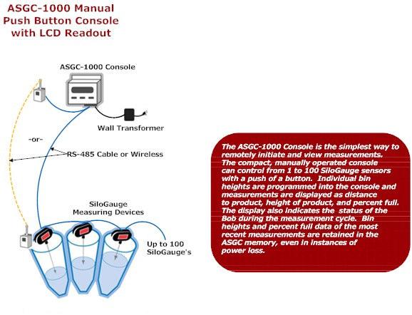
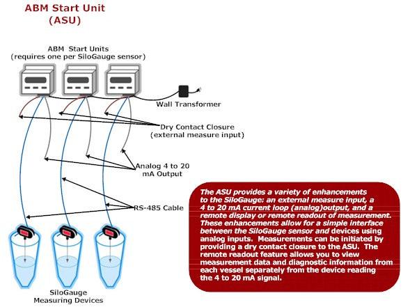
4 1.0 INTRODUCTION The ABM Sensors SiloGauge ASG-2000 is a remote on demand level measurement sensing unit. It is designed to work in conjunction with a Personal Computer running windows 95/98, NT, or 2000, an ABM Sensors ASGC-1000 console, or an ABM Sensors ASU (Remote Start Unit). In operation, the ASG-2000 lowers a weighted Bob to the surface of the product, measuring the distance. A microcontroller counts the pulses from an encoder. Slack in the cable is detected when the Bob reaches the surface, causing the motor to reverse and retract the Bob. The retract distance is also measured for diagnostic purposes to assure that the Bob fully retracts. General system diagrams showing use with a personal computer, ASGC-1000 console, and an ASU controller are illustrated in Figures 1a through 1c. ebob Software that runs on Windows XP Pro or Vista controls up to 100 SiloGauge units from one location with the standard RS485 interface box. The ebob software also provides current inventory, extended inventory, measuring scheduling, and vendor managed inventory and site status through faxing an . The ASGC-1000 is a stand alone console which can control and display measurements of up to 30 vessels. The ASU is a single vessel controller and provides 4 to 20 ma output for interfacing with other control systems.
5
6 2.0 INSTALLATION 2.1 LOCATION AND MOUNTING The SiloGauge remote unit is mounted on the top of the storage vessel using a 3 inch NPT coupling. If a 3 inch NPT floor flange is used, it must be on a flat level surface to provide a vertical mount for the unit. For measuring dry solids which involve an angle of repose, it is recommended that the unit be mounted 1/6 th of the vessel diameter in from the side, see Figure 2. A mounting flange template is provided on last page of this manual for a standard 3 inch NPT floor flange with a 5-1/8 inch bolt circle. 1/6 D SmartBob Remote Storage Vessel Material Fill D 2.2 RS485 NETWORK WIRING The ASG-2000 remotes are connected by a shielded twisted pair cable referred to as an RS485 network. This cable must run from one remote to the next connecting each remote in a daisy-chained fashion with no stub branch runs. All connections should be made at the terminals on the circuit board, see Figures 3&4. Be careful to maintain the proper wiring polarity at each terminal connection. The shield on the RS485 cable must be connected to the shield terminal on the circuit board, not to the enclosure ground. 2.3 NETWORK TERMINATION On each ASG-2000 remote unit, ASGC-1000, ASU, and RS485 interface module, there is a network termination switch, labeled NTR. The two units on each end of the RS485 daisy chained network must have their NTR switch placed in the ON position. All other units on the network must have this switch set to the OFF position. See Figures 3. NOTE: When installing the ASG-2000 in locations where moisture or moist air could enter the electrical compartment through the electrical conduit, the conduit openings should be adequately sealed with a duct seal compound.
7 R3 R25 R11 Q3 R5 R16 S2 R38 U6 R24 R34 R10 U7 R15 C8 R12 R13 D1 R18 C11 D6 R9 R39 R17 C10 DS6 R4 U5 R31 C4 C12 D5 R2 U2 DS2 R29 C9 DS5 C7 R30 R19 XT1 C13 D2 LSB R26 U1 DS4 U4 Q1 R6 REFER TO TABLE IN COVER DS3 C6 R27 R36 R22 U3 JP3 S1 MSB R3 R25 R11 Q3 R5 R16 S2 R38 U6 R24 R34 R10 U7 R15 C8 R12 R13 D1 R18 C11 D6 R9 R39 R17 C10 DS6 R4 U5 R31 C4 C12 D5 R2 U2 DS2 R29 C9 DS5 C7 R30 R19 XT1 C13 D2 LSB R26 U4 U1 DS4 Q1 R6 REFER TO TABLE IN COVER DS3 C6 R27 R36 R22 U3 JP3 S1 MSB RS485 WIRING FROM CONSOLE, RS485 INTERFACE. OR PREVIOUS SBR II RS485 cable BELDEN 9463 or equiv. - SHD RS485 J1 NTR ON OFF RET-HI S3 C16 D8 RET-LOW S4 S5 PROTO JP1 A D7 CYCLE B C15 TRANSMIT BUSY - SHD RS485 J1 NTR RS485 WIRING TO NEXT SBR II OR CONSOLE. ON OFF RET-HI S3 C16 D8 RET-LOW S4 S5 PROTO JP1 A D7 CYCLE B C15 TRANSMIT BUSY THE RS485 WIRING MUST BE IN A DAISY CHAIN WIRING SCHEME TO THE PC BOARD AT EACH UNIT. THE NTR SWITCH AT EACH END OF THE RS485 WIRING MUST BE IN THE ON POSITION. ALL NTR SWITCHES IN BETWEEN K1 MUST BE IN THE OFF POSITION. JP4 R35 HiR LowR Motor J2 R40 J3 OVERRIDE GROUND Q2 POWER R7 R21 R20 R32 DB1 R8 C14 K2 R14 R37 D3 STATUS D4 R28 C1 R33 C5 FAULTH FAULTL PTC PCB ASS'Y # BIN ADDRESS C2 R23 R1 ENCODER C3 POWER DS1 OVERRIDE JP4 R35 R40 GROUND J3 HiR LowR Motor K1 Q2 POWER J2 R7 R21 R20 R32 R8 C14 STATUS R14 R28 R37 D3 D4 K2 DB1 C1 R33 C5 FAULTH FAULTL PTC PCB ASS'Y # BIN ADDRESS C2 R23 ENCODER C3 R1 POWER DS1 115 VAC FIGURE POWER WIRING All wiring should be installed according to local and/or national codes. Refer to Figures 4 5 for the connection of the power wiring. The AC input power connects to the 2 pole terminal block located on the motor mount bracket. The neutral wire should be connected to the terminal on the right and the LINE conductor connected to the terminal on the left. The terminal on the left wires thru the fuse to the transformer. A green ground screw is provided in the SiloGauge enclosure for electrically grounding the unit. A good electrical ground must to connected to the ASG-2000 for safety and to bleed off any static electrical charges that might build up in the ASG It is recommended that both the power and the RS485 communication cable be ran in metal conduit. 2.5 SETTING THE ADDRESS The ABM Sensors ebob version 5.0 software can accommodate up to 100 ASG-2000 remote units with the standard RS485 interface. The ASGC-1000 console can accommodate up to 100 ASG-2000 remote units. Therefore a unique address must be set for each remote. Refer to Figure 4 and Table 1 regarding setting the address each for remote. This figure and table are also located on the inside cover of the ASG-2000 enclosure. The ASU console only operates with one SiloGauge remote. The address of a remote unit operating with an ASU must be set to #1.
8 Communication RS NTR Ret-Hi Ret-Low Cycle ON OFF Protocol A B Jumper Bin Address Hi R LN Low R RED BLK RED GRN WHT BLK Ground Neutral Line Transformer Sec. 16 VAC Fuse Power ASG-2000 WIRING DIAGRAM FIGURE 5
9 BIN ADDRESS BIN ADDRESS DIP SWITCHES BIN DIP SWITCH SETTINGS DIP SWITCH SETTINGS ADDRESS ON OFF OFF OFF OFF OFF OFF OFF 65 ON OFF OFF OFF OFF OFF ON OFF 2 OFF ON OFF OFF OFF OFF OFF OFF 66 OFF ON OFF OFF OFF OFF ON OFF 3 ON ON OFF OFF OFF OFF OFF OFF 67 ON ON OFF OFF OFF OFF ON OFF 4 OFF OFF ON OFF OFF OFF OFF OFF 68 OFF OFF ON OFF OFF OFF ON OFF 5 ON OFF ON OFF OFF OFF OFF OFF 69 ON OFF ON OFF OFF OFF ON OFF 6 OFF ON ON OFF OFF OFF OFF OFF 70 OFF ON ON OFF OFF OFF ON OFF 7 ON ON ON OFF OFF OFF OFF OFF 71 ON ON ON OFF OFF OFF ON OFF 8 OFF OFF OFF ON OFF OFF OFF OFF 72 OFF OFF OFF ON OFF OFF ON OFF 9 ON OFF OFF ON OFF OFF OFF OFF 73 ON OFF OFF ON OFF OFF ON OFF 10 OFF ON OFF ON OFF OFF OFF OFF 74 OFF ON OFF ON OFF OFF ON OFF 11 ON ON OFF ON OFF OFF OFF OFF 75 ON ON OFF ON OFF OFF ON OFF 12 OFF OFF ON ON OFF OFF OFF OFF 76 OFF OFF ON ON OFF OFF ON OFF 13 ON OFF ON ON OFF OFF OFF OFF 77 ON OFF ON ON OFF OFF ON OFF 14 OFF ON ON ON OFF OFF OFF OFF 78 OFF ON ON ON OFF OFF ON OFF 15 ON ON ON ON OFF OFF OFF OFF 79 ON ON ON ON OFF OFF ON OFF 16 OFF OFF OFF OFF ON OFF OFF OFF 80 OFF OFF OFF OFF ON OFF ON OFF 17 ON OFF OFF OFF ON OFF OFF OFF 81 ON OFF OFF OFF ON OFF ON OFF 18 OFF ON OFF OFF ON OFF OFF OFF 82 OFF ON OFF OFF ON OFF ON OFF 19 ON ON OFF OFF ON OFF OFF OFF 83 ON ON OFF OFF ON OFF ON OFF 20 OFF OFF ON OFF ON OFF OFF OFF 84 OFF OFF ON OFF ON OFF ON OFF 21 ON OFF ON OFF ON OFF OFF OFF 85 ON OFF ON OFF ON OFF ON OFF 22 OFF ON ON OFF ON OFF OFF OFF 86 OFF ON ON OFF ON OFF ON OFF 23 ON ON ON OFF ON OFF OFF OFF 87 ON ON ON OFF ON OFF ON OFF 24 OFF OFF OFF ON ON OFF OFF OFF 88 OFF OFF OFF ON ON OFF ON OFF 25 ON OFF OFF ON ON OFF OFF OFF 89 ON OFF OFF ON ON OFF ON OFF 26 OFF ON OFF ON ON OFF OFF OFF 90 OFF ON OFF ON ON OFF ON OFF 27 ON ON OFF ON ON OFF OFF OFF 91 ON ON OFF ON ON OFF ON OFF 28 OFF OFF ON ON ON OFF OFF OFF 92 OFF OFF ON ON ON OFF ON OFF 29 ON OFF ON ON ON OFF OFF OFF 93 ON OFF ON ON ON OFF ON OFF 30 OFF ON ON ON ON OFF OFF OFF 94 OFF ON ON ON ON OFF ON OFF 31 ON ON ON ON ON OFF OFF OFF 95 ON ON ON ON ON OFF ON OFF 32 OFF OFF OFF OFF OFF ON OFF OFF 96 OFF OFF OFF OFF OFF ON ON OFF 33 ON OFF OFF OFF OFF ON OFF OFF 97 ON OFF OFF OFF OFF ON ON OFF 34 OFF ON OFF OFF OFF ON OFF OFF 98 OFF ON OFF OFF OFF ON ON OFF 35 ON 0N OFF OFF OFF ON OFF OFF 99 ON ON OFF OFF OFF ON ON OFF 36 OFF OFF ON OFF OFF ON OFF OFF 100 OFF OFF ON OFF OFF ON ON OFF 37 ON OFF ON OFF OFF ON OFF OFF 101 ON OFF ON OFF OFF ON ON OFF 38 OFF ON ON OFF OFF ON OFF OFF 102 OFF ON ON OFF OFF ON ON OFF 39 ON ON ON OFF OFF ON OFF OFF 103 ON ON ON OFF OFF ON ON OFF 40 OFF OFF OFF ON OFF ON OFF OFF 104 OFF OFF OFF ON OFF ON ON OFF 41 ON OFF OFF ON OFF ON OFF OFF 105 ON OFF OFF ON OFF ON ON OFF 42 OFF ON OFF ON OFF ON OFF OFF 106 OFF ON OFF ON OFF ON ON OFF 43 ON ON OFF ON OFF ON OFF OFF 107 ON ON OFF ON OFF ON ON OFF 44 OFF OFF ON ON OFF ON OFF OFF 108 OFF OFF ON ON OFF ON ON OFF 45 ON OFF ON ON OFF ON OFF OFF 109 ON OFF ON ON OFF ON ON OFF 46 OFF ON ON ON OFF ON OFF OFF 110 OFF ON ON ON OFF ON ON OFF 47 ON ON ON ON OFF ON OFF OFF 111 ON ON ON ON OFF ON ON OFF 48 OFF OFF OFF OFF ON ON OFF OFF 112 OFF OFF OFF OFF ON ON ON OFF 49 ON OFF OFF OFF ON ON OFF OFF 113 ON OFF OFF OFF ON ON ON OFF 50 OFF ON OFF OFF ON ON OFF OFF 114 OFF ON OFF OFF ON ON ON OFF 51 ON ON OFF OFF ON ON OFF OFF 115 ON ON OFF OFF ON ON ON OFF 52 OFF OFF ON OFF ON ON OFF OFF 116 OFF OFF ON OFF ON ON ON OFF 53 ON OFF ON OFF ON ON OFF OFF 117 ON OFF ON OFF ON ON ON OFF 54 OFF ON ON OFF ON ON OFF OFF 118 OFF ON ON OFF ON ON ON OFF 55 ON ON ON OFF ON ON OFF OFF 119 ON ON ON OFF ON ON ON OFF 56 OFF OFF OFF ON ON ON OFF OFF 120 OFF OFF OFF ON ON ON ON OFF 57 ON OFF OFF ON ON ON OFF OFF 121 ON OFF OFF ON ON ON ON OFF 58 OFF ON OFF ON ON ON OFF OFF 122 OFF ON OFF ON ON ON ON OFF 59 ON ON OFF ON ON ON OFF OFF 123 ON ON OFF ON ON ON ON OFF 60 OFF OFF ON ON ON ON OFF OFF 124 OFF OFF ON ON ON ON ON OFF 61 ON OFF ON ON ON ON OFF OFF 125 ON OFF ON ON ON ON ON OFF 62 OFF ON ON ON ON ON OFF OFF 126 OFF ON ON ON ON ON ON OFF 63 ON ON ON ON ON ON OFF OFF 127 ON ON ON ON ON ON ON OFF 64 OFF OFF OFF OFF OFF OFF ON OFF 128 OFF OFF OFF OFF OFF OFF OFF ON
10 . 2.6 EXTERNAL OVERRIDE This feature can be used to prohibit measurements during a vessel filling cycle. The IMS software will notify the user that measurement cannot be taken while a filling operation is in progress. Located on the SiloGauge circuit board in the upper left corner (just below the RS485 terminals), is the terminal block labeled OVERRIDE. A connection must exist across these terminals for normal operation of the remote unit, see Figure 6. A contact on an external relay can be used to disable the remote unit during a fill cycle to prevent burying the Bob. The use of this feature is optional, if not used, leave the factory installed jumper in the terminal block. OVERRIDE Located on PCB NC C External Relay Coil FIGURE TESTING THE REMOTE OPERATION IMPORTANT: Complete the SiloGauge INSTALLATION CHECKLIST, included with this manual, before attempting to operate the units. 3.1 MANUAL OPERATION FROM REMOTE UNIT Once the SiloGauge Remote is installed and wired properly it can be manually cycled to verify proper operation. To perform the manual test: Open the electrical side of the remote unit. Press the CYCLE button located at the top of the printed circuit board. The unit will immediately lower the probe Bob to the surface and return. Replace the electrical side cover. 3.2 TROUBLESHOOTING If the remote fails to cycle, verify that the Input Power is present at the terminal block and that the POWER LED located on the circuit board (in lower right corner), is lit. The LED should be lit whenever the power is present at the terminal block and that the POWER LED located on the circuit board (in lower right corner), is lit. This LED should be lit whenever the power is present at the board terminals. If the unit still does not operate, consult the factory at
11 4.0 AIR PURGE SYSTEM Located on the lower right side of each SiloGauge remote unit is a ¼ NPT air fitting. This fitting can be used to connect an external source of dry, clean air or noncombustible gas to the remote housing. By adding pressure to the remote housing that is slightly greater than that in the vessel, material and dust from the vessel is prevented from entering into the unit. The external pressure should be one (1) psi greater than the ambient pressure in the storage vessel and should be free from moisture and other contaminates. 5.0 WARRANTY AND CUSTOMER SERVICE 5.1 LIMITED WARRANTY The manufacturer warrants this equipment for two (2) years according to the following terms: 1.) This warranty extends to the original purchaser only and commences on the date of original purchase. The original purchaser must mail to the manufacturer the Warranty Registration card to confirm the equipment purchase. Failure to do so may void the warranty. 2.) The manufacturer will repair or replace any part of this equipment found to be defective, provided such part is delivered prepaid to the factory. Manufacturer s obligation is limited to the cost of material and labor to repair or replace and does not include transportation expenses. 3.) This warranty shall not apply to any product that has, in our judgment, been tampered with, altered, subject to misuse, neglect or accident. In addition, the warranty does not extend to repairs made necessary by normal wear. 4.) This warranty is in lieu of all other warranties, expressed or implied. 5.2 CUSTOMER SERVICE ABM Sensors offers a toll-free Customer Service phone number, You may call the Customer Service Department for technical and application assistance Monday through Friday from 8:00 AM to 5:00 PM Central Time. International customers call us at or reach us via Fax at questions to info@abm Sensors.com. Note: This equipment has been tested and found to comply with the limits for Class A digital device, puasuant to part 15 of the FCC rules. These limits are designed to provide reasonable protection against harmful interference when the equipment is operated in a commercial environment. This equipment generates, uses, and can radiate radio frequency energy and if not installed and used in accordance with the instruction manual, may cause harmful interference in which case the user will be required to correct the interference at their own expense.
12 CABLE REPLACEMENT INSTRUCTIONS Before Starting Disconnect the power source. Remove the flat cover plate on the front of the remote housing. Idler Arm Pulley Cable Stop Crimps Cable Replacement 1. Loosen the ¼ set screw located on the hub of the supply pulley then remove the supply pulley assembly. 2. Remove and discard the old cable from the supply pulley. 3. Thread the bare end of the cable through the hub until the Cable Stop Crimps are positioned as shown in the illustration. 4. Tighten the #6 set screw located on the outside of the supply pulley hub. This will secure and ground the cable crimps. 5. Reassemble the supply pulley and tighten the ¼ set screw. 6. Skip to the Threading The Cable. Timing Pulley Supply Pulley Idler Pulley Kit Replacement 1. Loosen the ¼ set screw located on the hub of the supply pulley then remove the supply pulley assembly. 2. Remove and discard the old supply pulley and cable. 3. Assemble the new supply pulley replacement kit. 4. Skip to Threading the Cable. Threading the Cable Thread the cable over the top of the idler arm pulley, over the top of the front groove of the idler pulley, under the timing pulley, then over the top of the back groove of the idler pulley as shown in the illustration. Then thread the cable down through the brushes and threaded mount assembly.
13 NOTE: At this point you should refer to the attached manual instruction sheet Limiting Stainless Steel Cable. Follow steps 2 through 6. Loading the Supply Pulley 1. Reconnect the power source. 2. If loading the supply pulley is necessary, pull the cable taunt. Load supply pulley by pressing the RET-HI button located on the circuit board. Pressing this button will start the supply pulley turning in a clockwise direction, with the cable winding over the top. Keep the cable taunt until the pulley is full. When the supply pulley is full, release the RET-HI button. 3. Replace the cable wiper brushes and reattach the cover.
14 Probe Options BBP-1 This Polypropylene Bob is designed for granular materials from 20 lbs. per cubic foot and greater. BBP-2 This bob is a hollow inverted 6 cone made of stainless steel and is designed for bulk products with a density from 1.5 lbs. to 20 lbs. per cubic foot. This Bob may also be used in liquid applications. BBP-3 This Bob is designed for granular material with a density from 20 lbs. per cubic foot and greater. The BBP-3 bob should be filled with a material that is compatible with the material that is stored in the storage bin. Total weight of the Bob when full should be 16 to 20 oz. The BBP-3 Bob is made from an engineering plastic which will not damage the material handling auger in the unlikely event that the Bob should become separated from the unit. BBP-4 This submersible Bob is made of 316 stainless steel and was designed to penetrate a liquid to measure the solid substance which lies at the bottom of that liquid.
15 Probe Options BBP-7 This stainless steel Bob is designed for granular materials from 20 lbs. per cubic foot and Greater. This Bob is Shipped standard with every SiloGauge remote. BBP-8 This Bob is a hollow inverted 4 cone made of stainless steel and is designed for bulk products with a density from 5 lbs. to 20 lbs. per cubic foot. This Bob should not be used in liquids.
16 LIMITING STAINLESS STEEL CABLE ASG-2000 It is important to limit the length of cable on the ASG-2000 remote, so that the bob is not lowered into an airlock, screw conveyor, or any other area that the bob might become trapped in. The ASG-2000 remote is shipped with 90 of cable unless otherwise specified. Disregard these instructions if the unit was ordered with the exact amount of cable necessary for your vessel. This procedure for limiting the cable should be done before the unit is installed: 1. Remove the cable from the supply pulley by pressing the CYCLE button on the top of the PC board. Keeping the cable taunt, pull on the cable as the cable spools off the pulley. When the line is all paid out, the motor will reverse and try to rewind the cable. Hold the cable tight so it cannot rewind. The motor should now be shut off. 2. From the throat of the ASG-2000, measure the height of your vessel or the maximum distance you want the bob to travel into your vessel. 3. Cut the stainless steel cable through the suredrop, thimble and bob as shown. 4. Thread the stainless steel cable through the suredrop, thimble and bob as shown. 5. Tighten and crimp the noose around the thimble. Locate and crimp the round crimp as shown. 6. Test crimp by pulling on the cable and bob. 7. Rewind the cable onto the supply pulley or lower the cable and bob into the vessel. Tow rewind onto the supply pulley: Pull the cable taunt. Load the supply by pressing (and hold) the RET-HI button located on the circuit board. Pressing this button will start the supply pulley turning in a clockwise direction, with the cable winding over the top. 8. Continue installation of the unit on your vessel Ball Stop Round Crimp Round Crimp At This Location For Uncoated Cable Only Cap Oval Crimp (2) Required Thimble Bob
17 Mounting Options High Temperature Mount Standard Flange Mount Pipe Extension Mount
18 SILOGAUGE REMOTE MOUNTING TEMPLATE DIAMETER BOLT HOLE CIRCLE 4.25 DIAMETER CUTOUT OPENING 5/16 DIAMETER THRU HOLE 6 HOLES EQUALLY SPACED
19 Suredrop Cable Release System Assembly Instructions Assemble the suredrop cable release system in the order as shown in the figure below. 1) Ball Stop 2) Round Crimp 3) Ball Stop 4) Cap 5) Ball Stop 6) Oval Crimp 7) Thimble 8) Cable The Teflon balls are designed to be a tight fit on the cable. This is so the balls will not slip on the cable. Therefore the Teflon balls may be somewhat difficult to assemble onto the cable. The exception to this is with the balls used on an uncoated stainless steel cable. These balls are over size and will assemble with ease. Using pliers, hold the cable about 1/8 inch from the end of the cable. This will keep the cable taut and straight while you press the cable through the Teflon ball. After all items are located as show, crimp the crimps in place. When compressing the crimps, be careful not to over tighten. Over tightening could cut and damage the cable Ball Stop Round Crimp Round Crimp At This Location For Uncoated Cable Only Cap Oval Crimp (2) Required Thimble Bob
TABLE OF CONTENTS SPECIFICATIONS...3 SAFETY SUMMARY...4 INTRODUCTION...5, 6 INSTALLATION...7, 8, 9, 10 TESTING THE REMOTE OPERATION AIR PURGE...
 SBR II SmartBob Remote Unit INSTALLATION AND OPERATING INSTRUCTIONS PLEASE READ CAREFULLY TABLE OF CONTENTS SPECIFICATIONS...3 SAFETY SUMMARY...4 INTRODUCTION...5, 6 INSTALLATION...7, 8, 9, 10 TESTING
TS1 SMARTBOB REMOTE UNIT. INSTALLATION and OPERATING INSTRUCTIONS PLEASE READ CAREFULLY
 TS1 SMARTBOB REMOTE UNIT INSTALLATION and OPERATING INSTRUCTIONS PLEASE READ CAREFULLY Division of Garner Industries 7201 No. 98th Street P.O. Box 29709 Lincoln, NE 68507 Lincoln, NE 68529 (402) 434-9102
SmartBob AO. BinMaster: Division of Garner Industries 7201 N. 98th St., Lincoln, NE
 BinMaster: Division of Garner Industries 7201 N. 98th St., Lincoln, NE 68507 402-434-9102 email: info@binmaster.com www.binmaster.com OPERATING INSTRUCTIONS PLEASE READ CAREFULLY 925-0312 Rev B TABLE OF
PRO REMOTE Series CAPACITANCE PROBE
 Price $5.00 PRO REMOTE Series CAPACITANCE PROBE OPERATING INSTRUCTIONS READ THOROUGHLY BEFORE INSTALLING EQUIPMENT TABLE OF CONTENTS GENERAL SPECIFICATIONS...3 1.0 INTRODUCTION...4 2.0 APPLICATIONS...4
PRO REMOTE 25 LV CAPACITANCE PROBE
 Price $5.00 PRO REMOTE 25 LV CAPACITANCE PROBE OPERATING INSTRUCTIONS READ THOROUGHLY BEFORE INSTALLING EQUIPMENT Distribué par : 2 rue René Laennec 51500 Taissy France Fax: 03 26 85 19 08, Tel : 03 26
TABLE OF CONTENTS GENERAL SPECIFICATIONS... 3 SAFETY SUMMARY INTRODUCTION INSTALLATION Location and Mounting Input
 BMRX Series ROTARY LEVEL CONTROL OPERATING INSTRUCTIONS PLEASE READ CAREFULLY TABLE OF CONTENTS GENERAL SPECIFICATIONS... 3 SAFETY SUMMARY... 4 1.0 INTRODUCTION... 5 2.0 INSTALLATION...5 2.1 Location and
BMRX Series Rotary Level Indicator
 BMRX Series Rotary Level Indicator BinMaster: Division of Garner Industries 7201 N. 98th St., Lincoln, NE 68507 402-434-9102 email: info@binmaster.com www.binmaster.com OPERATING INSTRUCTIONS PLEASE READ
BMRX Series ROTARY LEVEL CONTROL
 BMRX Series ROTARY LEVEL CONTROL OPERATING INSTRUCTIONS PLEASE READ CAREFULLY 925-0292 Rev C TABLE OF CONTENTS GENERAL SPECIFICATIONS... 3 SAFETY SUMMARY... 4 1.0 INTRODUCTION... 5 2.0 INSTALLATION...
CVR-625. Compact Vibrating Rod Instruction Manual
 CVR-625 Compact Vibrating Rod Instruction Manual BinMaster: Division of Garner Industries 7201 N. 98th St., Lincoln, NE 68507 402-434-9102 email: info@binmaster.com www.binmaster.com OPERATING INSTRUCTIONS
OPERATING INSTRUCTIONS PLEASE READ CAREFULLY
 OPERATING INSTRUCTIONS PLEASE READ CAREFULLY 925-0330 Rev 0 0416 TABLE OF CONTENTS SAFETY SUMMARY... 3 SPECIFICATIONS... 4 1.0 INTRODUCTION/DESCRIPTION.... 5 2.0 LOCATION AND MOUNTING... 5 3.0 CONNECTIONS
A419 Series Electronic Temperature Controls with NEMA 1 or NEMA 4X Watertight Enclosures
 Installation Instructions Issue Date April 8, 2008 A419 Series Electronic Temperature Controls with NEMA 1 or NEMA 4X Watertight Enclosures Application IMPORTANT: The A419 Series Electronic Temperature
SmartBob II SBR.1 A M1 H X X XX. Base. Mounting Plate. Cable. Heater. Probe
 SmartBob II Base Mark X if none Sample Sample SBR.1 A 1 035 M1 H X X XX Cable Probe Mounting Plate Heater Cable Length (begin with 0 if less than 100 ft.) Entered in feet up to 150 feet Cable Type 1: C1
A419ABG-3C Electronic Temperature Control
 Installation Instructions Issue Date June 16, 2003 A419ABG-3C Electronic Temperature Control Application IMPORTANT: Use this A419ABG-3C Electronic Temperature Control only as an operating control. Where
CBC-300 Series & CBC-300C Series Dual Channel Adjust Clutch/Brake Controls
 CBC-300 Series & CBC-300C Series Dual Channel Adjust Clutch/Brake Controls P-269-89-0408 Installation Installation & Operating Instructions Contents Introduction........................... 2 Specifications.........................
TC26-B Vehicle Sensor
 Section 1 General Description The Model TC26-B is a microprocessor controlled vehicle sensor with a variable range. It is designed to trigger the operation of a traffic controller. The TC26-B will only
Film-Tech. The information contained in this Adobe Acrobat pdf file is provided at your own risk and good judgment.
 Film-Tech The information contained in this Adobe Acrobat pdf file is provided at your own risk and good judgment. These manuals are designed to facilitate the exchange of information related to cinema
the weight-and-cable assembly.) The standard cast-aluminum weight (Figure 1a) is suited to about 80 to 90 percent of applications; other specialized w
 The standard cast-aluminum weight (Figure 1a) is suited to about 80 to 90 percent of applications; other specialized w") Reprinted from Powder and Bulk Engineering, March 2006 www.powderbulk.com What s new in smart weight-and-cable bin level sensors Joe Lewis Monitor Technologies LLC This article covers the latest generation
Reprinted from Powder and Bulk Engineering, March 2006 www.powderbulk.com What s new in smart weight-and-cable bin level sensors Joe Lewis Monitor Technologies LLC This article covers the latest generation
Installation Instructions
 Quick-Mount Visual Instructions for Mechanical Installation Quick-Mount Visual Instructions 1. Rotate the damper to its failsafe position. If the shaft rotates counterclockwise, mount the CCW side of the
Use and Care Guide.
 Model # Part # 53301111 L-40-802-SV-N-BZ 53301112 L-40-802-SV-N-W Use and Care Guide LED OUTDOOR RE LIGHT Questions, problems, missing parts? Call ETi SSL Customer Service 8:30 a.m. 5 p.m., EST, Monday
Patient Care Facility
 ISIMET Patient Care Facility DLA Controller Individual Room Configuration Style 1 W/ Ver 4.41 pcb & Pulse Relay pcb Installation, Operations, Start-up and Maintenance Instructions Meets all Standards for
Drug Testing Labs. Style 2 W/ Ver 4.41 pcb & Pulse Relay pcb(s) Installation, Operations, Start-up and Maintenance Instructions
 Installation, Operations, Start-up and Maintenance Instructions") ISIMET Drug Testing Labs DLA Controller Style 2 W/ Ver 4.41 pcb & Pulse Relay pcb(s) Installation, Operations, Start-up and Maintenance Instructions Meets all Standards for Canadian Industrial Control
ISIMET Drug Testing Labs DLA Controller Style 2 W/ Ver 4.41 pcb & Pulse Relay pcb(s) Installation, Operations, Start-up and Maintenance Instructions Meets all Standards for Canadian Industrial Control
Patient Care Facility Multiple Room Configuration Style 3 W/ Ver 4.41 pcb & Pulse Relay pcb(s)
") ISIMET DLA Controller Patient Care Facility Multiple Room Configuration Style 3 W/ Ver 4.41 pcb & Pulse Relay pcb(s) Installation, Operations, Start-up and Maintenance Instructions Application: The DLA
ISIMET DLA Controller Patient Care Facility Multiple Room Configuration Style 3 W/ Ver 4.41 pcb & Pulse Relay pcb(s) Installation, Operations, Start-up and Maintenance Instructions Application: The DLA
ACC Series Power Conditioner OPERATION & INSTALLATION MANUAL
 ACC Series Power Conditioner OPERATION & INSTALLATION MANUAL PHASETEC digital power conditioners are designed to safely operate electrical equipment in the harshest power quality environments. With a wide
RESISTIVITY MONITOR/CONTROLLERS
 RESISTIVITY MONITOR/CONTROLLERS Installation Operation Maintenance User Manual for Models: 750, 752, 753, 762 2450 Impala Drive Carlsbad, CA 92010-7226 USA Tel: 1-760-438-2021 Fax: 1-800-869-7668 / 1-760-931-9189
Installation Instructions
 Quick-Mount Visual Instructions for Quick-Mount Visual Instructions 1. Rotate the damper to its failsafe position. If the shaft rotates counterclockwise, mount the CCW side of the actuator out. If it rotates
Patient Care Facility
 ISIMET Patient Care Facility DLA Controller Individual Room Configuration Style 1 W/ Ver 4.41 pcb & Pulse Relay pcb Installation, Operations, Start-up and Maintenance Instructions Meets all Standards for
Drug Testing Labs. Style 2 W/ Ver 4.41 pcb & Pulse Relay pcb(s) Installation, Operations, Start-up and Maintenance Instructions
 Installation, Operations, Start-up and Maintenance Instructions") ISIMET Drug Testing Labs DLA Controller Style 2 W/ Ver 4.41 pcb & Pulse Relay pcb(s) Installation, Operations, Start-up and Maintenance Instructions Meets all Standards for Canadian Industrial Control
ISIMET Drug Testing Labs DLA Controller Style 2 W/ Ver 4.41 pcb & Pulse Relay pcb(s) Installation, Operations, Start-up and Maintenance Instructions Meets all Standards for Canadian Industrial Control
TOPAZ 12 WALL PACK INSTALLATION & MAINTENANCE GUIDE (Part # LIT A)
") TOPAZ 12 WALL PACK INSTALLATION & MAINTENANCE GUIDE (Part # LIT-29499-1A) Contractor: Please read these instructions before starting installation. After installation, please forward this guide to the user
TOPAZ 12 WALL PACK INSTALLATION & MAINTENANCE GUIDE (Part # LIT-29499-1A) Contractor: Please read these instructions before starting installation. After installation, please forward this guide to the user
CBC-300 & CBC Series Dual Channel Adjust Clutch/Brake Controls
 CBC-300 & CBC-300- Series Dual Channel Adjust Clutch/Brake Controls P-205-WE 89-0549 Installation & Operating Instructions An Altra Industrial Motion Company Contents Introduction... 2 Specifications...
Installation and Operating Manual
 Model u002 & u003 Installation and Operating Manual Ultrasonic Level Switch 60 Great Hill Road Naugatuck, CT 06770 ph: 203-729-6434 fax: 203-729-6696 www.innovativesensing.com Read this Manual Before Installing
8460SRC Replacement Chassis for Scully ST-6 and Biclops Monitors
 8460SRC Replacement Chassis for Manual Part Number: OPTI-THERM is a registered trademark of CIVACON, A Dover Company QUICK-START is a registered trademark of CIVACON, A Dover Company Biclops is a registered
MP461SC Flex Probes* Installation Instructions
 PNEUMERCATOR Liquid Level Control Systems MP461SC Flex Probes* Installation Instructions Model MP461SC Magnetostrictive Flex Probes For use with the following consoles: TMS2000 TMS3000 NOTE: MP461SC PROBES
WF-5100 Series True Sine Wave Inverters
 Operator s Manual WF-5100 Series True Sine Wave Inverters WF-9900 Series WF-5118 WF-5120 ( The Inverter model number is located on the label on top of the enclosure) Distributed in the U.S.A. and Canada
AUTO-PUMP 120 VAC AIR COMPRESSOR SYSTEM INSTRUCTION MANUAL. 170 Cherry Avenue West Sayville, NY
 INSTRUCTION MANUAL AUTO-PUMP 120 VAC AIR COMPRESSOR SYSTEM MODEL #: #:091-9B-1 091-9B-1 INPUT :120 volt, 50/60 Hz, 1.8 AMPS OUTPUT: 100 PSI MAXIMUM File: 091-9B-1_revA1_GEN3 Rev: A1 Revised By:PSS/JRN
RAPID Environment Control INSTALLATION GUIDE. Ver 99C. RAPID Environment Control. Creep
 RAPID Environment Control INSTALLATION GUIDE Ver 99C RAPID Environment Control 1 2 3 4 5 6 7 8 9 0 Room Ambient Creep S Y S T E M S Variable Ouput 2 Indicator Variable Ouput 1 Indicator S Y S T E M S Increase
Model GD-70D4A-XX Supplement to the GD-70D Operator s Manual
 Model GD-70D4A-XX Supplement to the GD-70D Operator s Manual Part Number: 71-0192RK Revision: A Released: 1/27/17 www.rkiinstruments.com WARNING Read and understand this instruction manual before operating
CTFRP Series Power Supplies
 CTFRP Series Power Supplies Ferroresonant Non-Standby Power Supplies User Manual Myers Power Products 6/2013 CTFRP Series Manual Chapter 1 General Information The Myers CTFRP Series Power Supply provides
ACSI MODEL 1406BB-04-AO POWER SUPPLY INSTALLATION INSTRUCTIONS
 II 1400-10 ACSI MODEL 1406BB-04-AO POWER SUPPLY INSTALLATION INSTRUCTIONS Features: Up to 1.95 Amps Load Capacity Class 2 Rated Outputs Overload, Over Voltage, and Short Circuit Protection Standby Battery
IOM. LP-100 & LP-200 Pulse Point TM Installation & Operation Manual
 IOM LP-100 & LP-200 Pulse Point TM Installation & Operation Manual CAUTION It is essential that all instructions in this manual be followed precisely to ensure proper operation of the equipment. SAFETY
BroadBand PowerShield. 20 AHr Battery. User Manual
 BroadBand PowerShield 20 AHr Battery User Manual 990-1316A 10/2004 Chapter 1 General Information The PowerShield provides a power source for broadband telephony applications. Important Safety Instructions
TRAILER AUXILIARY POWER SYSTEM (TAPS) INSTALLATION GUIDE V1.10
 INSTALLATION GUIDE V1.10") TRAILER AUXILIARY POWER SYSTEM (TAPS) INSTALLATION GUIDE V1.10 TAPS INSTALLATION GUIDE V1.10 1 TRAILER AUXILIARY POWER SYSTEM CONTENTS General Information and System Logic... 2 Diagrams... 3 System Diagram
TRAILER AUXILIARY POWER SYSTEM (TAPS) INSTALLATION GUIDE V1.10 TAPS INSTALLATION GUIDE V1.10 1 TRAILER AUXILIARY POWER SYSTEM CONTENTS General Information and System Logic... 2 Diagrams... 3 System Diagram
USE AND CARE GUIDE DUALCHECK CIRCUIT TESTER
 Item # 1002 153 664 Model #CE-VD7504GFI USE AND CARE GUIDE DUALCHECK CIRCUIT TESTER Questions, problems, missing parts? Before returning to the store, call Commercial Electric Customer Service 8 a.m. 7
Feed Scale Installation & Operator s Instruction Manual
 Installation & Operator s Instruction Manual May 004 CTB Inc. Warranty CTB Inc. Warranty CTB Inc. warrants each new C-Collect product manufactured by it to be free from defects in material or workmanship
PowerLogic High Density Metering System 4-Meter Enclosure Installation Guide
 PowerLogic High Density Metering System 4-Meter Enclosure Installation Guide 7002-0289-00 Instruction Bulletin HAZARD CATEGORIES AND SPECIAL SYMBOLS Read these instructions carefully and look at the equipment
CIVACON GROUND VERIFICATION RACK MONITOR SYSTEM and ASSOCIATED EQUIPMENT
 GROUND VERIFICATION RACK MONITOR SYSTEM and ASSOCIATED EQUIPMENT INSTALLATION AND WIRING INSTRUCTIONS MANUAL 8030 MANUAL PART NUMBER JANUARY 2011. 4304 MATTOX RD. KANSAS CITY, MO 64150 TABLE OF CONTENTS
6. Electrical. 7. Settings. 8. Quick
 Grundfos Variable Speed Circulator Pump Pumps Incorporating the VS, Variable Speed Control 1. Shipment Inspection Page 2 2. General Page 2 3. Operational Limits Page 3 4. Pump Installation Page 4 5. Installation
Grundfos Variable Speed GRUNDFOS INSTRUCTIONS. Installation and Operation
 GRUNDFOS INSTRUCTIONS Grundfos Variable Speed Installation and Operation Pumps Incorporating the (VS) Variable Speed Control with Date Code 0838 or higher 1. 2. 3. 4. Shipment Inspection General Features
Product Overview. Product Identification. Amps One CT Two CTs Three CTs
 AH06 (optional mounting bracket for small, medium, and large CTs) DANGER HAZARD OF ELECTRIC SHOCK, EXPLOSION, OR ARC FLASH Follow safe electrical work practices. See NFPA 70E in the USA, or applicable
FM200 FLOW/NO-FLOW MONITOR INSTALLATION AND TECHNICAL MANUAL 120 VAC MODEL 6/1/2017
 FM200 FLOW/NO-FLOW MONITOR INSTALLATION AND TECHNICAL MANUAL 120 VAC MODEL 6/1/2017 Maxi-Tronic, Inc. 417 Wards Corner Road Loveland, OH 45140 513.398.2500 800.659.8250 FAX: 513.398.2536 info@maxitronic.com
MODEL MSD MOTION CONTROL INSTALLATION AND OPERATION
 CONVEYOR COMPONENTS COMPANY 130 Seltzer Road, PO Box 167 Croswell, MI 48422 USA PHONE: (810) 679-4211 TOLL FREE (800) 233-3233 FAX: (810) 679-4510 Email: info@conveyorcomponents.com http://www.conveyorcomponents.com
L-Series: LIQUID LEVEL FLOAT SWITCH. Single-Point, Vertically-Mounted Liquid Level Float Switch INSTALLATION AND OPERATIONS MANUAL
 L-Series: L001, L002, L003, L170, L175, L176, L177, L178, L180, L190 AND L195 LIQUID LEVEL FLOAT SWITCH INSTALLATION AND OPERATIONS MANUAL Single-Point, Vertically-Mounted Liquid Level Float Switch L001
E.S.P. Embedded Sensing Probes for Motor Brushes
 E.S.P. Embedded Sensing Probes for Motor Brushes 2/13 Installation & Operating Manual MN609 Any trademarks used in this manual are the property of their respective owners. Important: Be sure to check www.baldor.com
PCS GEAR SELECT MODULE USER GUIDE v4.0
 PCS GEAR SELECT MODULE USER GUIDE v4.0 Ph: 1.804.227.3023 www.powertraincontrolsolutions.com Powertrain Control Solutions 1 Introduction 1.1 Included Components 1 - GSM Cable Motor Enclosur 1 - GSM Driver
P200 P/I Transducer. Installation, Operation, and Maintenance Instructions INTRODUCTION
 INTRODUCTION Scope This manual provides instructions for the installation, adjustment, maintenance, and parts ordering of the P200 Pneumatic-to-Current P/I Transducer. Due to its over-engineered design,
MD10. Engine Controller. Installation and User Manual for the MD10 Engine Controller. Full Version
 MD10 Engine Controller Installation and User Manual for the MD10 Engine Controller. Full Version File: MartinMD10rev1.4.doc May 16, 2002 2 READ MANUAL BEFORE INSTALLING UNIT Receipt of shipment and warranty
TOPAZ 24 DIMMER RACK INSTALLATION & MAINTENANCE GUIDE (Part # LIT A)
") TOPAZ 24 DIMMER RACK INSTALLATION & MAINTENANCE GUIDE (Part # LIT-29132-1A) Contractor: Please read these instructions before starting installation. After installation, please forward this guide to the
TOPAZ 24 DIMMER RACK INSTALLATION & MAINTENANCE GUIDE (Part # LIT-29132-1A) Contractor: Please read these instructions before starting installation. After installation, please forward this guide to the
Owner's Manual. mycharge name and logo are registered trademarks of RFA Brands RFA Brands. All Rights Reserved. Patent Pending.
 REGISTER Your Product At: www.mycharge.com Your valuable input regarding this product will help us create the products you will want in the future. PLEASE TAKE A MOMENT NOW mycharge name and logo are registered
HYGRODYNAMICS DIGITAL DEW POINT MONITOR PC BOARD MODEL 6392N & 6392N2 TABLE OF CONTENTS
 HYGRODYNAMICS DIGITAL DEW POINT MONITOR PC BOARD MODEL 6392N & 6392N2 TABLE OF CONTENTS INTRODUCTION... 2 SPECIFICATIONS... 2 INSTALLATION... 3 PC Board Mounting...3 Sensor Installation...3 Manifold Assembly...4
SmarTire TPMS Maintenance Hand Tool. Revision User Manual
 SmarTire TPMS Maintenance Hand Tool Revision 1.03 User Manual Page 2 Table of Contents FCC Compliance Label...4 User Interface Illustration...4 Introduction...5 Testing Tire Sensors...5 Main Menu...6 Main
Super-Safe-Plus Roto-Bin-Dicator
 Super-Safe-Plus Roto-Bin-Dicator for your most demanding applications... Offers both mechanical and electronic sensing in one reliable Point Level Sensor... Level control with added confidence Under normal
R820 REV2 SERIES SCR POWER CONTROLS NOVEMBER 2017
 R80 REV SERIES SCR POWER CONTROLS NOVEMBER 017 Product overview The Viconics R80 series SCR power controls are designed for cost effective, precise modulation of electric loads for most electric heating
U S A INSTALLATION GUIDE EP400 / E8-B
 U S A INSTALLATION GUIDE EP400 / E8-B www.easycar-.com Before Beginning the Installation 1. Wire Connection Guides Please read this entire installation guide before beginning the installation. The installation
12 Series Linear Actuators. Operation & Maintenance Manual, Analog Positioner Installation
 12 Series Linear Actuators Operation & Maintenance Manual, Analog Positioner Installation 6810 POWERLINE DR.-FLORENCE, KY. 41042 - TELEPHONE 859-727-7890, TOLL FREE 1-800-662-9424 FAX. 859-727-4070, E-MAIL:
WF-5110R True Sine Wave Inverter
 Operator s Manual WF-5110R True Sine Wave Inverter WF-9900 Series WF-5110R ( The Inverter model number is located on the label on top of the enclosure) Distributed in the U.S.A. and Canada by ARTERRA DISTRIBUTION
ITS-50R TRANSFER SWITCH OWNER S MANUAL
 ITS-50R OWNER S MANUAL IOTA Engineering Transfer Switches provide automatic power switching between two or three separate 120/240 volt AC input sources, including powercords, onboard generators, onboard
Application Engineering Europe
 Date of last update: Feb-12 Ref: D7.8.4/0112-0212/E Application Engineering Europe CORESENSE DIAGNOSTICS FOR STREAM REFRIGERATION COMPRESSORS 1/17 1 Introduction CoreSense is an ingredient brand name for
F-4600 INLINE ULTRASONIC FLOW METER Installation and Operation Guide
 F-4600 INLINE ULTRASONIC FLOW METER Installation and Operation Guide 11451 Belcher Road South, Largo, FL 33773 USA Tel +1 (727) 447-6140 Fax +1 (727) 442-5699 1054-7 / 34405 www.onicon.com sales@onicon.com
A419 Series Electronic Temperature Controls with Display and NEMA 1 or NEMA 4X Watertight Enclosures
 A419 Issue Date February 10, 2003 A419 Series Electronic Temperature Controls with Display and NEMA 1 or NEMA 4X Watertight Enclosures The A419 series controls are single-stage, electronic temperature
FHC-1D user manual. Features
 Phason The Fan and Heater Control (FHC-1D) automatically controls the temperature in a room by adjusting the speed of variable speed fans and controlling a heater interlock. When the temperature is at
Owner's Manual. For latest instructions please go to
 mycharge name and logo are registered trademarks of RFA Brands. 2012-2013 RFA Brands. All Rights Reserved. Patent Pending. Made in China. IB-MYC0600 Owner's Manual For latest instructions please go to
U00X ULTRASONIC LEVEL SWITCH. Ultrasonic Liquid Level Switches INSTALLATION AND OPERATIONS MANUAL. For Models: U002, U003 & U004
 U00X ULTRASONIC LEVEL SWITCH INSTALLATION AND OPERATIONS MANUAL Ultrasonic Liquid Level Switches For Non-Hazardous Locations For Models: U002, U003 & U004 READ THIS MANUAL PRIOR TO INSTALLATION This manual
Installation Instructions
 Installation Instructions Welcome to your Workhorse Servo Motor. We know you re going to love this quiet, energy-saving, durable motor with its great features like fully adjustable speed settings and high
007 Tank Monitor. WARNING Never use with gasoline or highly flammable liquids.
 Model #7575 Recommended Installation, Maintenance and Inspection Instructions 007 Tank Monitor 7575 Important safety instructions - save these instructions in a readily accessible location. WARNING Never
ROTARY Point Level Measurement for Inventory Control
 Measure. Detect. Alert. ROTARY Point Level Measurement for Inventory Control Detect high and low levels while protecting valuable inventory with tried-and-true rotary level indicators from BinMaster. Made
TRAC-3 TENSION READOUT AND CONTROL
 Magnetic Power Systems, Inc. 1626 Manufacturers Drive. Fenton, MO 63026 Tel: 636.343.5550 Fax: 636.326.0608 magpowr@magpowr.com INSTRUCTION MANUAL TRAC-3 READOUT AND CONTROL For Control of Magnetic Particle
PowerMaster MODEL MBG. Installation Manual U L R UL 325 AND UL 991 LISTED MEDIUM DUTY BARRIER GATE OPERATOR TABLE OF CONTENTS
 PowerMaster TABLE OF CONTENTS MODEL MBG MEDIUM DUTY BARRIER GATE OPERATOR Important Safety Information...... 3 System Designer Safety Instructions.......4 Installer Safety Instructions....... 5 Installation
DeSoto NEMA 4X EMERGENCY LIGHTING UNIT. U.S. Versions: 6V- DM90X618 / DM90X654 12V- DM90X1254 / DM90X12100 INSTALLATION INSTRUCTIONS
 DeSoto U.S. Versions: 6V- DM90X618 / DM90X654 12V- DM90X1254 / DM90X12100 NEMA 4X EMERGENCY LIGHTING UNIT INSTALLATION INSTRUCTIONS U.S. Patent No.s 6,135,624; 6,193,395; 6,502,044 B1; D505,222; IMPORTANT
L007 LIQUID LEVEL FLOAT SWITCH. Side-Mounted Liquid Level Float Switch INSTALLATION AND OPERATIONS MANUAL
 L007 LIQUID LEVEL FLOAT SWITCH INSTALLATION AND OPERATIONS MANUAL Side-Mounted Liquid Level Float Switch READ THIS MANUAL PRIOR TO INSTALLATION This manual provides information on the L007 Side- Mounted
ARCHITECTURAL CONTROL SYSTEMS, INCORPORATED ST. LOUIS, MISSOURI
 II 1400-6 ARCHITECTURAL CONTROL SYSTEMS, INCORPORATED ST. LOUIS, MISSOURI ACSI 1426-04-AO ELECTRIC LATCH RETRACTION CONTROLLER INSTALLATION INSTRUCTIONS I.D. 1092, REV. C INSTALLATION For C-UL Listed applications,
Sentinel Field Satellite Controller
 WARNING HIGH VOLTAGE 115V M AP Sentinel Field Satellite Controller Installation Instructions Important: For your protection and the safety of the product user, please comply with all Caution and Warning
- Wiring Brochure Zone Manager 335
 - Wiring Brochure W 335 12/08 1 Information Brochure Choose controls to match application 2 Application Brochure Design your mechanical applications Rough-in Wiring Rough-in wiring instructions 3 4 Wiring
VP-4124/VP-4124-E 24/48 VOLT DC SWITCHING POWER SUPPLY
 Issue 5 24/48 VOLT DC SWITCHING POWER SUPPLY INTRODUCTION These instructions provide the specifications, installation and maintenance information for the VP-4124 and VP-4124-E, 24/48 Volt Power Supplies.
Installation Instructions
 Quick-Mount Visual Instructions for Mechanical Installation Quick-Mount Visual Instructions. Rotate the damper to its failsafe position. If the shaft rotates counterclockwise, mount the CCW side of the
BAK1500 INSTALLATION/OWNER'S MANUAL Compact Amplified Subwoofer
 BAK1500 INSTALLATION/OWNER'S MANUAL Compact Amplified Subwoofer PREPARATION Getting Started Thank you for purchasing the Dual BAK1500 compact amplified subwoofer. Although Dual has attempted to ensure
LMPLC COOKSON OWNER'S MANUAL FDO A & B SOLID STATE INDUSTRIAL DUTY FIRE DOOR OPERATOR. B2/C2 Wiring 2 YEAR WARRANTY FDO 1/2 HP FDO A & B
 COOKSON OWNER'S MANUAL FDO A & B SOLID STATE INDUSTRIAL DUTY FIRE DOOR OPERATOR LMPLC CONTROL LMPLC CONTROL WIRED B/C Wiring FDO / HP FDO A & B FDO HP FDO A & B YEAR WARRANTY Serial # (located on electrical
DUST ALERT BinMaster Price Book binmaster.com Subject to change without notice 1
 DUST ALERT - 3000 BinMaster Price Book 01-2019 binmaster.com Subject to change without notice 1 DUST ALERT - 3000 Dust Alert - 3000 The Dust Alert with integrated electronics and sensing probe utilizes
model ps600 Address all communications and shipments to: FEDERAL SIGNAL CORPORATION
 MODEL: PS600 HZ: 60 A model ps600 installation and service manual for federal model ps600 FEDERAL SIGNAL CORPORATION POWER SUPPLY VOLTS: SERIES: 120VAC FEDERAL SIGNAL CORPORATION UNIVERSITY PARK, IL. U.S.A.
- Wiring Brochure Zone Manager 336
 - Wiring Brochure W 336 12/08 1 Information Brochure Choose controls to match application Application Brochure Design your mechanical applications 2 3 Rough-in Wiring Rough-in 4 Wiring Brochure Wiring
Application Engineering
 Application Engineering February, 2009 Copeland Digital Compressor Controller Introduction The Digital Compressor Controller is the electronics interface between the Copeland Scroll Digital Compressor
OPERATING INSTRUCTIONS AND SERVICE MANUAL MODEL MP-3903 TIMER
 OPERATING INSTRUCTIONS AND SERVICE MANUAL MODEL MP-3903 TIMER EFFECTIVE S.N. 16,600, FEB. 28, 2001 1. General Information TABLE OF CONTENTS 1.1 Description 1.2 Identification 1.3 Damage 1.4 Damage Claim
INSTALLATION AND MAINTENANCE MANUAL FORM #PM-126 REV A 12/09
 HAND CRANK & MOTORIZED POWER CORD REELS: SERIES 1125PC SERIES: 1125PC HAND CRANK SERIES: 1125PC MOTORIZED COXREELS The technical data and images which appear in this manual are for informational purposes
ICM 326HN/327HN Line Voltage Head Pressure Control Installation, Operation & Application Guide
 ICM 326HN/327HN Line Voltage Head Pressure Control With built-in transformer Optional heat pump override ICM326HN ICM327HN Installation, Operation & Application Guide For more information on our complete
C.E. Niehoff & Co. C653/C653A and C625 Alternators Troubleshooting Guide NOTICE. Hazard Definitions. Battery Charge Volt and Amp Values
 C.E. Niehoff & Co. C653/C653A and C625 Alternators Troubleshooting Guide Hazard Definitions These terms are used to bring attention to presence of hazards of various risk levels or to important information
John Deere (4730 & 4830) with Proportional Main Lift Installation Manual JD08
 with Proportional Main Lift Installation Manual JD08") JD08 John Deere (4730 & 4830) with Proportional Main Lift Installation Manual Printed in Canada Copyright 2009 by NORAC Systems International Inc. Reorder P/N: UC5-BC-JD08-INST Rev N (John Deere 4730 &
JD08 John Deere (4730 & 4830) with Proportional Main Lift Installation Manual Printed in Canada Copyright 2009 by NORAC Systems International Inc. Reorder P/N: UC5-BC-JD08-INST Rev N (John Deere 4730 &
ICM325HN. Head Pressure Control with Optional Heat Pump Override. Installation, Operation & Application Guide
 ICM325HN Head Pressure Control with Optional Heat Pump Override Temperature sensitive control regulates head pressure Installation, Operation & Application Guide For more information on our complete range
ME AGS Auto Gen Start Network System with Inverter and Remote for Coach Generators Operator s Manual
 ME AGS Auto Gen Start Network System with Inverter and Remote for Coach Generators Operator s Manual 2 2010 Enerdrive Pty Ltd ME AGS Operator s Manual Auto Gen Start Network System with Inverter and Remote
SP-32 & SP-32D SP-33, SP-33D SP-34, SP-34D. Description. Specifications. Single Stage Temperature Control
 SP-32, SP-32D SP-33, SP-33D SP-34, SP-34D Single Stage Temperature Control Description The SP-3x and SP-3xD series of controls are single stage, general purpose, temperature controls with wide application
ACTIVE ELECTRODELESS SENSORS Instruction Manual
 W A L C H E M An Iwaki America Company Active Electrodeless Sensors ACTIVE ELECTRODELESS SENSORS Instruction Manual Five Boynton Road Hopping Brook Park Holliston, MA 01746 USA TEL: 508-429-1110 FAX: 508-429-7433
Switch Pro w/ Compact Junction Box A_1_ Series Owner s Manual
 Warranty, Service & Repair To register your product with the manufacturer, go to the Flowline website for on-line registration. The website address is as follows: www.flowline.com On-line Warranty Registration
Switch-Tek Horizontal and Vertical And Float-Point Float Switches LV20, LV21, LV35, LV36, LH25, LH29, LH35, AV_6 Series 22AUG 08 Rev A
 Switch-Tek Horizontal and Vertical And Float-Point Float Switches LV20, LV21, LV35, LV36, LH25, LH29, LH35, AV_6 Series 22AUG 08 Flowline, Inc. 10500 Humbolt Street Los Alamitos, CA 90720 Tel: (562) 598-3015