Switch-Tek Horizontal and Vertical And Float-Point Float Switches LV20, LV21, LV35, LV36, LH25, LH29, LH35, AV_6 Series 22AUG 08 Rev A
|
|
|
- Valentine McDaniel
- 5 years ago
- Views:
Transcription

 431-8507 www.flowline.")
1 Switch-Tek Horizontal and Vertical And Float-Point Float Switches LV20, LV21, LV35, LV36, LH25, LH29, LH35, AV_6 Series 22AUG 08 Flowline, Inc Humbolt Street Los Alamitos, CA Tel: (562) Fax: (562) AUG 08 Switch-Tek Float Series 1 of 14
2 2 of 14 Switch-Tek Float Series 22 AUG 08
3 Preface This manual explains how to use the Switch-Tek series of horizontal and vertical floats. Warranty, Service & Repair To register your product with the manufacturer, go to the Flowline website for on-line registration. The website address is as follows: On-line Warranty Registration can be found under Contact Us in the Navigation Bar along the side of the home page. If for some reason your product must be returned for factory service, contact Flowline Inc. at (562) to receive a Material Return Authorization number (MRA), providing the following information: 1. Part Number, Serial Number 2. Name and telephone number of someone who can answer technical questions related to the product and its application. 3. Return Shipping Address 4. Brief Description of the Symptom 5. Brief Description of the Application Once you have received a Material Return Authorization number, ship the product prepaid in its original packing to: Flowline Factory Service MRA Humbolt Street Los Alamitos, CA To avoid delays in processing your repair, write the MRA on the shipping label. Please include the information about the malfunction with your product. This information enables our service technicians to process your repair order as quickly as possible. 22 AUG 08 Switch-Tek Float Series 3 of 14
4 Warranty Flowline warrants to the original purchaser of its products that such products will be free from defects in material and workmanship under normal use and service for a period which is equal to the shorter of one year from the date of purchase of such products or two years from the date of manufacture of such products. This warranty covers only those components of the products which hare non-moving and not subject to normal wear. Moreover, products which are modified or altered, and electrical cables which are cut to length during installation are not covered by this warranty. Flowline s obligation under this warranty is solely and exclusively limited to the repair or replacement, at Flowline s option, of the products (or components thereof) which Flowline s examination proves to its satisfaction to be defective. FLOWLINE SHALL HAVE NO OBLIGATION FOR CONSEQUENTIAL DAMAGES TO PERSONAL OR REAL PROPERTY, OR FOR INJURY TO ANY PERSON. This warranty does not apply to products which have been subject to electrical or chemical damage due to improper use, accident, negligence, abuse or misuse. Abuse shall be assumed when indicated by electrical damage to relays, reed switches or other components. The warranty does not apply to products which are damaged during shipment back to Flowline s factory or designated service center or are returned without the original casing on the products. Moreover, this warranty becomes immediately null and void if anyone other than service personnel authorized by Flowline attempts to repair the defective products. Products which are thought to be defective must be shipped prepaid and insured to Flowline s factory or a designated service center (the identity and address of which will be provided upon request) within 30 days of the discovery of the defect. Such defective products must be accompanied by proof of the date of purchase. Flowline further reserves the right to unilaterally waive this warranty and to dispose of any product returned to Flowline where: a. There is evidence of a potentially hazardous material present with product. b. The product has remained unclaimed at Flowline for longer than 30 days after dutifully requesting disposition of the product. THERE ARE NO WARRANTIES WHICH EXTEND BEYONDTHE DESCRIPTION ON THE FACE OF THIS WARRANTY. This warranty and the obligations and liabilities of Flowline under it are exclusive and instead of, and the original purchaser hereby waives, all other remedies, warranties, guarantees or liabilities, express or implied. EXCLUDED FROM THIS WARRANTY IS THE IMPLIED WARRANTY OF FITNESS OF THE PRODUCTS FOR A PARTICULAR PURPOSE OR USE AND THE IMPLIED WARRANTY OF MERCHANTABILITY OF THE PRODUCTS. This warranty may not be extended, altered or varied except by a written instrument signed by a duly-authorized officer of Flowline, Inc. 4 of 14 Switch-Tek Float Series 22 AUG 08
5 Table of Contents Introduction...6 Technology...6 Installation...7 Vertical Mounted Switches...7 Horizontal Mounted Switches...7 Environmental...8 Dimensions...8 Material Compatibility...9 Electrical interface...10 Typical Current and Voltage Ratings...10 AV_6 Series Float and Wire key...11 Specification...12 Maintenance...13 Cautions...13 Testing the Installations...13 Cleaning Procedure AUG 08 Switch-Tek Float Series 5 of 14
6 Introduction 1. Switches should be installed rigidly so the float or floats are free to move as the liquid level changes. 2. Switches should be mounted in a tank area free of severe turbulence or protected from such turbulence by appropriate and adequate slosh shields. 3. Vertical switch stems should be vertical for best results, but satisfactory operation is possible in most liquids with the stem at up to a 30 angle from vertical. 4. Side mount switch stems must be mounted with the arrow vertically either up or down depending on switch operation. 5. Care should be taken that switches are always operated within electrical ratings. 6. Orientation for standard Vertical switches can be changed from normally open to normally closed dry or vice versa by removing the float and reversing it in the stem, except with the LV , LV , LV and LV Technology Float switches consist of a float, magnet, reed switch and body/stem with mounting threads. When the probe is dry, the float rests on the bottom of the stem such that the magnet does not influence the reed switch. As the probe becomes immersed in liquid, the float becomes buoyant and the magnet elevates causing the reed switch to change state. 6 of 14 Switch-Tek Float Series 22 AUG 08
7 Installation Operation is stated in the tank dry position. Vertical Mounted Switches: o NC Operation: SS Floats: Witness mark (round circle) down. Plastic Floats: Magnets up. o NO Operation: SS Floats: Witness mark (round circle) up. Plastic Floats: Magnets down. *Note: LV , LV , LV and LV are not reversible. The LV and LV are Normally Closed. The LV and LV are Normally Open Horizontal Mounted Switches: o NC Operation: Arrow mounted vertically pointed down. o NO Operation: Arrow mounted vertically pointed up. 22 AUG 08 Switch-Tek Float Series 7 of 14
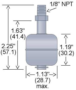
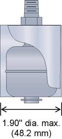
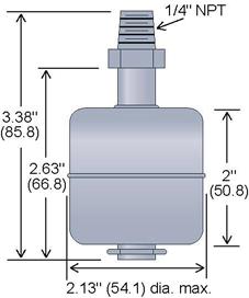
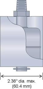
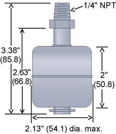
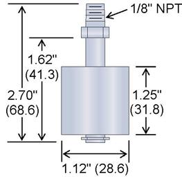
8 Environmental Dimensions LV35-S201 LV35-S401 LV36-S201 LV36-S401 LV36-S501 LV LH35-S201 LH LH LV & LV LV & LV of 14 Switch-Tek Float Series 22 AUG 08
 with 22 AWG, Teflon 24 wire. o The LH25-1201, LH25-2401, LV21-1101, LV21-1201 and LV20-1501 are made of Polypropylene () with 22 AWG, Teflon 24 wire.")
 with a Valox 420 stem and 22 AWG, HALAR jacketed 120 wire.")
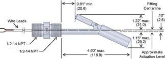
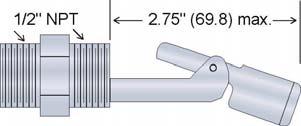
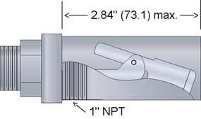
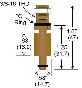
9 Dimensions (continued) LH AV16-S243, AV26-S243, AV36-S243, AV46-S243 and AV56-S243 AV26-S243 Shown Material Compatibility: o The LV36-S201, LV36-S401, LV35-S201, LV35-S401, LH35-S201 and LV36-S501 are made of 316 stainless steel () with 22 AWG, Teflon 24 wire. o The LH , LH , LV , LV and LV are made of Polypropylene () with 22 AWG, Teflon 24 wire. o The LV and LV are made of Polytetrafluoroethylene (PTFE) with 22 AWG, Teflon 24 wire. o The LH is made of Polypropylene () with a Valox 420 stem and 22 AWG, HALAR jacketed 120 wire. o The AV16-S243, AV26-S243, AV36-S243, AV46-S243 and AV56-S243 are made of 316 Stainless Steel () with a Polypropylene () enclosure. o Make sure that the switch is compatible with the application liquids. To determine the chemical compatibility between the sensor and its application liquids, refer to the Compass Corrosion Guide, available from Compass Publications ( ). 22 AUG 08 Switch-Tek Float Series 9 of 14
10 Electrical Interface Typical Current and Voltage Ratings Watts Voltage Current Amps AC 120 AC 100 DC 24 DC AC 120 AC 100 DC 24 DC AC 120 AC 100 DC 24 DC AC 120 AC 100 DC 24 DC Note: The ratings at right are for resistive loads only. For inductive loads, maximum switch life will be achieved if appropriate arc suppression is used. The following part numbers; LV36-S201, LV36-S401, LV35-S201, LV35-S401, LV , LV , LV , LV , LH35-S201, LH , LH and LH , are all two wire reed switch outputs where polarity does not matter. Part numbers LV36-S501 and LV are reed switch outputs with two additional wires that are used to output the 100-ohm RTD used to measure the temperature of the environment. 10 of 14 Switch-Tek Float Series 22 AUG 08
11 AV_6 Series Float and Wire Key SPST Switches AV16-S243 (1) Switch AV26-S243 (2) Switches AV36-S243 (4) Switches AV46-S243 (4) Switches AV56-S243 (5) Switches F-Dim RED E-Dim RED WHITE D-Dim RED WHITE BLUE C-Dim RED WHITE BLUE GREEN B-Dim BLACK BLACK BLACK BLACK BLACK A-Dim Total Stem Length Note: Each float will have a pair of colored wires for each level. For example, With a AV56-S243, the B-Dim float will have two black wires as the switch contact. 22 AUG 08 Switch-Tek Float Series 11 of 14
12 Part Number LV36-S201 LV36-S401 LV35-S201 LV35-S401 LV LV LV LV LH35-S201 LH LH Specifications Description Vertical small Vertical small w/ slosh shield Vertical large Vertical large w/ slosh shield Teflon, NC Teflon, NO Sub-minature, NC Sub-minature, NO Horizontal side mount Horz. side mount Horz. side mount w/ slosh shield Float Mat l Stem Mat l Max. Oper. Temp ( C) Max Pressure (PSIG) Standard Full-Size Vertical PFTE PFTE PFTE PTFE Float SG Nominal VA W SPST 60W SPST Fitting ¼ NPT ¼ NPT 1/8 NPT 1/8 NPT 1/8 27 NPT 1/8 27 NPT 3/8 16 NPT 3/8 16 NPT Standard Horizontal ½ NPT ½ NPT ½ NPT Vertical Floats with 100 Ohm RTD LV36-S501 Vertical SS ¼ NPT LV Vertical /8 NPT Configured (Multi-Level) Vertical Assembly AV16-S243 AV26-S243 AV36-S243 AV46-S243 AV56-S243 1-point float system 2-point float system 3-point float system 4-point float system 5-point float system LH Valox Interstitial Switch N/A 30W SPST 2 NPT 2 NPT 2 NPT 2 NPT 2 NPT Notes: Also applies to models with slosh shields The LV and LV are Normally Closed. The LV and LV are Normally Open. N/A 12 of 14 Switch-Tek Float Series 22 AUG 08
13 Maintenance Maintenance should consist of inspection to see that the float is free to move and not coated with any substance, which would change its weight or volume significantly. If this occurs, the float should be cleaned. This is easily accomplished without disturbing the installation. In addition, the stem may be wiped down to remove any build-up. The only repair possible in the field is replacement of either the float or stem. Dents or nicks on the float are usually of no consequence to operation. Cautions FLOWLINE manufactures a wide range of liquid level switches and technologies. While each of these switches are designed to operate in a wide variety of applications, it is the user's responsibility to select a switch model that is appropriate for the application, install it properly, perform tests of the installed system, and maintain all components. The failure to do so could result in property damage or serious injury. 1. The pressure, temperature and electrical limitations shown for the specified level switches must not be exceeded. 2. The pressures and temperatures must take into consideration possible surges in the temperature and pressure of the system. 3. The liquids used must be compatible with the materials of construction. Specifications of materials will be given upon request. 4. Life expectancy of the switch varies with applications. Contact the factory if life cycle testing is required. 5. Ambient temperature changes can affect switch set points, since specific gravities of liquids vary with temperature. Consult factory for assistance. 6. Level switches have been designed to be shock and vibration resistant. For maximum life, both shock and vibration should be minimized. Consult factory for assistance. 7. Excessive contaminants in fluid may inhibit float operation, and occasional wipe down may be necessary. 8. Level switches must not be field repaired 9. Physical damage to product may render product unserviceable. 10. Installation in a vessel made from magnetic materials may affect operation. Testing the installation: 1. Power: Turn on power to the controller and/or power supply. 2. Immersing the switch: Immerse the sensing tip in its application liquid, by filling the tank up to the switches point of actuation. An alternate method of immersing the switch during preliminary testing is to hold a cup filled with application liquid up to the switch's tip. 3. Test: With the switch being fluctuated between wet and dry states, the switch indicator light in the controller should turn on and off. If the controller doesn't have an input indicator, use a voltmeter or ammeter to ensure that the switch produces the correct signal. 4. Point of actuation: Observe the point at which the rising or falling fluid level causes the switch to change state, and adjust the installation of the switch if necessary. 22 AUG 08 Switch-Tek Float Series 13 of 14
14 Cleaning procedure: 1. Power: Make sure that all power to the switch, controller and/or power supply is completely disconnected. 2. Switch removal: If necessary, make sure that the tank is drained well below the switch prior to removal. Carefully, remove the sensor from the installation. Remove the outer screen by pushing on the screen and turning is slightly to disconnect is from the bayonet connector so that the float is exposed. 3. Cleaning the switch: Using a soft bristle brush and mild deter-gent, carefully wash the switch. Do not use harsh abrasives such as steel wool or sandpaper, which might damage the surface of the sensor. Do not use incompatible solvents, which may damage the sensor's or PVDF plastic body. Take particular care to remove any scaling from the float body and make sure that it moves freely. 4. Sensor installation: Follow the appropriate steps of installation as outlined in the Installation section of this manual. 14 of 14 Switch-Tek Float Series 22 AUG 08
AV16, AV26, AV36, AV46, AV56, LH25, LH29, LH35, LV20, LV21, LV35 & LV36 Series Manual
 Switch-Tek Horizontal, Vertical & Float-Point Float Switches AV16, AV26, AV36, AV46, AV56, LH25, LH29, LH35, LV20, LV21, LV35 & LV36 Series Manual Flowline, Inc. 10500 Humbolt Street, Los Alamitos, CA
Switch Pro w/ Compact Junction Box A_1_ Series Owner s Manual
 Warranty, Service & Repair To register your product with the manufacturer, go to the Flowline website for on-line registration. The website address is as follows: www.flowline.com On-line Warranty Registration
Switch-Pak. AU13, AV13 & AZ13 Series Owner s Manual. w/ Compact Relay Controller
 Switch-Pak w/ Compact Relay Controller AU13, AV13 & AZ13 Series Owner s Manual Flowline, Inc.. 10500 Humbolt Street, Los Alamitos, CA 90720. p 562.598.3015. f 562.431.8507. w flowline.com MN301430 Rev
Smart Trak. AU18, AU28, AU38, AU48, AV16, AV26, AV36, AV46, AZ18, AZ28, AZ38 & AZ48 Series Owner s Manual. w/ Compact Junction Box
 Smart Trak w/ Compact Junction Box AU18, AU28, AU38, AU48, AV16, AV26, AV36, AV46, AZ18, AZ28, AZ38 & AZ48 Series Owner s Manual Flowline, Inc.. 10500 Humbolt Street, Los Alamitos, CA 90720. p 562.598.3015.
CRICKET Alphasonic Level Transmitter Model LA12 Owner s Manual
 Warranty, Service and Repair To register your product with the manufacturer, fill out the enclosed warranty card and return it immediately to: FLOWLINE Inc. 10500 Humbolt Street Los Alamitos, CA 90720
LA19 Series Ricochet Battery Powered Level Transmitter and Display
 Warranty, Service & Repair To register your product with the manufacturer, fill out the enclosed warranty card and return it immediately to: Flowline Inc. 10500 Humbolt Street Los Alamitos, CA 90720. If
Optic Level Switch LO10 Series Owner s Manual
 Warranty, Service & Repair To register your product with the manufacturer, fill out the enclosed warranty card and return it immediately to: Flowline Inc. 10500 Humbolt Street Los Alamitos, CA 90720. If
Thermo Flo Thermal Dispersion Flow Switch FT10 & GT10 Series Manual
 Thermo Flo Thermal Dispersion Flow Switch FT10 & GT10 Series Manual Flowline Inc. 10500 Humbolt Street Los Alamitos, CA 90720 Tel: (562) 598 3015 Fax: (562) 431 8507 www.flowline.com Rev A FT900003 1 of
EchoPod. Technical Support. Model: DL14-(XX) Quick Start
 Quick Start") Technical Support For complete product documentation, video training, and technical support, go to www.flowline.com. For phone support, call 562-598-3015 from 8am to 5pm PST, Mon - Fri. (Please make sure
Technical Support For complete product documentation, video training, and technical support, go to www.flowline.com. For phone support, call 562-598-3015 from 8am to 5pm PST, Mon - Fri. (Please make sure
Switch Pro Remote Level Controller LC40, LC41 & LC42 Series Manual
 Switch Pro Remote Level Controller LC40, LC41 & LC42 Series Manual Flowline Inc. 10500 Humbolt Street Los Alamitos, CA 90720 Tel: (562) 598 3015 Fax: (562) 431 8507 www.flowline.com Rev A MNC40100 1 of
XP88 & XP89 Series Quick Start
 Ultrasonic Liquid Level Transmitter XP88 & XP89 Series Quick Start 2016 Flowline, Inc. All Rights Reserved Made in USA Flowline, Inc. 10500 Humbolt Street, Los Alamitos, CA 90720 p 562.598.3015 f 562.431.8507
LU23, LU28 & LU29 Series Quick Start
 Ultrasonic Liquid Level Transmitter LU23, LU28 & LU29 Series Quick Start 2016 Flowline, Inc. All Rights Reserved Made in USA Flowline, Inc. 10500 Humbolt Street, Los Alamitos, CA 90720 p 562.598.3015 f
EchoPod. DL10, DL14, DL24, DS14 & DX10 Series Quick Start. DL14-00 Shown Flowline, Inc. All Rights Reserved Made in USA
 EchoPod Ultrasonic Level Switch, Controller & Transmitter DL10, DL14, DL24, DS14 & DX10 Series Quick Start DL14-00 Shown 2016 Flowline, Inc. All Rights Reserved Made in USA Flowline, Inc. 10500 Humbolt
L-Series: LIQUID LEVEL FLOAT SWITCH. Single-Point, Vertically-Mounted Liquid Level Float Switch INSTALLATION AND OPERATIONS MANUAL
 L-Series: L001, L002, L003, L170, L175, L176, L177, L178, L180, L190 AND L195 LIQUID LEVEL FLOAT SWITCH INSTALLATION AND OPERATIONS MANUAL Single-Point, Vertically-Mounted Liquid Level Float Switch L001
LU27 Series Quick Start
 Ultrasonic Liquid Level Transmitter LU27 Series Quick Start 2016 Flowline, Inc. All Rights Reserved Made in USA Flowline, Inc. 10500 Humbolt Street, Los Alamitos, CA 90720 p 562.598.3015 f 562.431.8507
EchoPod. UG06 & UG12 Series Quick Start Flowline, Inc. All Rights Reserved Made in USA. Ultrasonic Liquid Level Transmitter
 EchoPod Ultrasonic Liquid Level Transmitter UG06 & UG12 Series Quick Start 2017 Flowline, Inc. All Rights Reserved Made in USA Flowline, Inc. 10500 Humbolt Street, Los Alamitos, CA 90720 p 562.598.3015
DeZURIK AFR3 Filter Regulator Used on Pneumatic Cylinder Actuators
 AFR3 Filter Regulator Used on Pneumatic Cylinder Actuators Instructions D11033 August 2013 Instructions These instructions provide information about AFR3 Filter Regulators. They are for use by personnel
L007 LIQUID LEVEL FLOAT SWITCH. Side-Mounted Liquid Level Float Switch INSTALLATION AND OPERATIONS MANUAL
 L007 LIQUID LEVEL FLOAT SWITCH INSTALLATION AND OPERATIONS MANUAL Side-Mounted Liquid Level Float Switch READ THIS MANUAL PRIOR TO INSTALLATION This manual provides information on the L007 Side- Mounted
L500 LIQUID LEVEL FLOAT SWITCH. Single or Multi-Point, Vertically-Mounted Liquid Level Float Switch INSTALLATION AND OPERATIONS MANUAL
 L500 LIQUID LEVEL FLOAT SWITCH INSTALLATION AND OPERATIONS MANUAL Single or Multi-Point, Vertically-Mounted Liquid Level Float Switch READ THIS MANUAL PRIOR TO INSTALLATION This manual provides information
S003 LIQUID LEVEL FLOAT SWITCH. Single or Multi-Point, Vertically-Mounted, Liquid Level Float Switch INSTALLATION AND OPERATIONS MANUAL
 S003 LIQUID LEVEL FLOAT SWITCH INSTALLATION AND OPERATIONS MANUAL Single or Multi-Point, Vertically-Mounted, Liquid Level Float Switch READ THIS MANUAL PRIOR TO INSTALLATION This manual provides information
EchoPod. UG01 & UG03 Series Quick Start Flowline, Inc. All Rights Reserved Made in USA. Ultrasonic Liquid Level Switch, Controller & Transmitter
 EchoPod Ultrasonic Liquid Level Switch, Controller & Transmitter UG01 & UG03 Series Quick Start 2017 Flowline, Inc. All Rights Reserved Made in USA Flowline, Inc. 10500 Humbolt Street, Los Alamitos, CA
1 2-Inch Station Outlet Valves
 ADI 1089M Certified ISO 9001:2000 1 2-Inch Station Outlet Valves Non-Return Type INSTALLATION AND OPERATION INSTRUCTIONS Before Installing or Operating, Read and Comply with These Instructions Controls
APCO CRF-100A RUBBER FLAPPER SWING CHECK VALVES
 APCO CRF-100A RUBBER FLAPPER SWING CHECK VALVES Instruction D12043 June 2016 DeZURIK Instructions These instructions provide installation, operation and maintenance information for APCO CRF-100A Rubber
L312 LIQUID LEVEL FLOAT SWITCH. Multi-Point, Vertically-Mounted Liquid Level Float Switch INSTALLATION AND OPERATIONS MANUAL
 LIQUID LEVEL FLOAT SWITCH INSTALLATION AND OPERATIONS MANUAL Multi-Point, Vertically-Mounted Liquid Level Float Switch READ THIS MANUAL PRIOR TO INSTALLATION This manual provides information on the Multi-
Full View Flow Indicator
 Full View Flow Indicator Threaded and Flanged Process Connection Installation / Operation / Maintenance Manual P.O. Box 1116 Twinsburg, OH 44087 Phone: 330/405-3040 Fax: 330/405-3070 E-mail: view@ljstar.com
Electromagnetic Particle Brakes Model: PRB-H
 P-223-3 819-0370 Electromagnetic Particle Brakes Model: PRB-H Installation Instructions Table of Contents Introduction............................2 Installation Instructions....................3 Start
APCO ASR-400/450 SEWAGE AIR RELEASE VALVES
 APCO ASR-400/450 SEWAGE AIR RELEASE VALVES Instruction D12005 December 2012 Instructions These instructions provide installation, operation and maintenance information for the APCO ASR- 400/450 Sewage
8 Light Controller. Instruction Manual. With Light Timer 240 Volts. Product # INNOVATING SINCE 1995
 8 Light Controller With Light Timer 240 Volts Product #703008 Instruction Manual INNOVATING SINCE 1995 1 www.titancontrols.net 8 Light Controller This manual covers the following: Warnings & Cautions 8
SIDE-WIND, A-FRAME TRAILER JACK. Model Due to continuing improvements, actual product may differ slightly from the product described herein.
 SIDE-WIND, A-FRAME TRAILER JACK Model 95157 Assembly And Operation Instructions Due to continuing improvements, actual product may differ slightly from the product described herein. 3491 Mission Oaks Blvd.,
OPERATING INSTRUCTIONS PLEASE READ CAREFULLY
 OPERATING INSTRUCTIONS PLEASE READ CAREFULLY 925-0330 Rev 0 0416 TABLE OF CONTENTS SAFETY SUMMARY... 3 SPECIFICATIONS... 4 1.0 INTRODUCTION/DESCRIPTION.... 5 2.0 LOCATION AND MOUNTING... 5 3.0 CONNECTIONS
Reach ins, Freeezers & Refrigerators Installation & Operation Manual
 Reach ins, Freeezers & Refrigerators Installation & Operation Manual BSR23 BSF23 BSR49 BSF49 BSR72 BSF72 IMPORTANT SAFETY INSTRUCTIONS (SAVE THESE INSTRUCTIONS) Visit us on the web at www.blueairinc.com
Smart -Trak. AU23, AV23, AZ23 Series Manual. With Compact Relay Controller
 Smart -Trak With Compact Relay Controller AU23, AV23, AZ23 Series Manual Flowline, Inc. 10500 Humbolt Street, Los Alamitos, CA 90720 p 562.598.3015 f 562.431.8507 w flowline.com MN301410 Rev A Introduction
Model 616 Rotating Disk Electrode Instruction Manual
 Model 616 Rotating Disk Electrode Instruction Manual 219303 C / 1202 Printed in USA Advanced Measurement Technology, Inc. a/k/a Princeton Applied Research, a subsidiary of AMETEK, Inc. WARRANTY Princeton
Owner s Manual & Safety Instructions
 Owner s Manual & Safety Instructions Save This Manual Keep this manual for the safety warnings and precautions, assembly, operating, inspection, maintenance and cleaning procedures. Write the product s
Blue Air. Commercial Refrigeration Inc. Installation & Operation Manual Chef Bases
 Blue Air Commercial Refrigeration Inc. Installation & Operation Manual Chef Bases Please read this manual completely before installing or operating this unit! BACB53 BACB71 BACB74 BACB83 BACB86 BACB96
For Hazardous Locations
 L500E LIQUID LEVEL FLOAT SWITCH INSTALLATION AND OPERATIONS MANUAL Single or Multi-Point, Vertically-Mounted Liquid Level Float Switch For Hazardous Locations READ THIS MANUAL PRIOR TO INSTALLATION This
PVI 1800/PVI Residential/Commercial Grid-Tied Photovoltaic Inverter WARRANTY MANUAL. Subject to Change REV , Solectria Renewables
 PVI 1800/PVI 2500 WARRANTY MANUAL Residential/Commercial Grid-Tied Photovoltaic Inverter 2009, Solectria Renewables Subject to Change REV 10.09 1 Product Warranty & RMA Policy 1.1 Warranty Policy The Solectria
SUBMERSIBLE MINI-PUMP
 SUBMERSIBLE MINI-PUMP Model 41287 Set up And Operating Instructions Diagrams within this manual may not be drawn proportionally. Due to continuing improvements, actual product may differ slightly from
Blue Air. Commercial Refrigeration Inc. Installation & Operation Manual Glass Door Countertop Refrigerator
 Blue Air Commercial Refrigeration Inc. Installation & Operation Manual Glass Door Countertop Refrigerator Please read this manual completely before installing or operating this unit! BAGR7 Blue Air reserves
INSTALLATION & OPERATION MANUAL
 INSTALLATION & OPERATION MANUAL VTC180 DC/DC Converter An ISO9001 and AS9100 Registered Company Battery Chargers Inverters Power Supplies Voltage Converters 8128 River Way, Delta B.C. V4G 1K5 Canada T.
Level Alert Model Multi-Switch Liquid Level Sensor. Assembly and Installation Instructions
 Level Alert Model 2000 Multi-Switch Liquid Level Sensor Assembly and Installation Instructions Kit Form Each unit is provided in kit form with step-by-step instructions, making it extremely easy to custom
Air Actuated Hydraulic Bottle Jack on Wheels
 Operating Instructions & Parts Manual Air Actuated Hydraulic Bottle Jack on Wheels Model Number 18127 18207 Capacity 12 Ton 20 Ton Shinn Fu Co. of America, Inc. 2002 10939 N. Pomona Avenue Kansas City,
25 GALLON PORTABLE OIL LIFT
 25 GALLON PORTABLE OIL LIFT Model 92859 SET UP AND OPERATING INSTRUCTIONS Diagrams within this manual may not be drawn proportionally. Due to continuing improvements, actual product may differ slightly
INSTALLATION & OPERATION MANUAL
 INSTALLATION & OPERATION MANUAL VTC140/240 SERIES Voltage Converters An ISO9001 and AS9100 Registered Company Battery Chargers Inverters Power Supplies Voltage Converters 8128 River Way, Delta B.C. V4G
TABLE OF CONTENTS. Page 1
 TABLE OF CONTENTS Safety Precautions and Warnings... 2 Introduction... 3 EZ-CHARGE Battery Conductance Testers... 3 EZ-CHARGE 100 Features... 3 EZ-CHARGE 200 Features... 4 Text Styles Used in this Manual...
A48 / A48B (base plate) BATTERY CHARGER
 BATTERY CHARGER") A48 / A48B (base plate) BATTERY CHARGER CPN41054 ISSUE DATE: 12315-8/98 ECN/DATE 106 BRADROCK DRIVE DES PLAINES, IL. 60018-1967 (847) 299-1188 FAX: (847)299-3061 15349-07-07/02 16041 6/03 14575-2/01 INSTRUCTION
A48 / A48B (base plate) BATTERY CHARGER CPN41054 ISSUE DATE: 12315-8/98 ECN/DATE 106 BRADROCK DRIVE DES PLAINES, IL. 60018-1967 (847) 299-1188 FAX: (847)299-3061 15349-07-07/02 16041 6/03 14575-2/01 INSTRUCTION
Model NTX7 Series Automatic Battery Charger User s Manual Rev. 1.0 October 17, 2006
 B R A N D Model NTX7 Series Automatic Battery Charger User s Manual Rev. 1.0 October 17, 2006 For Sales, Support and Service phone: 407-331-4793 fax: 407-331-4708 website: www.xenotronix.com email: information@xenotronix.com
Operator's Manual. Storage System. Ultrasound Probe Cabinet. Manufactured by:
 Storage System Ultrasound Probe Cabinet Operator's Manual Manufactured by: CIVCO Medical Solutions 102 First Street South Kalona, IA 52247 USA 319.248.6757 / 800.445.6741 WWW.CIVCO.COM Copyright 2018 All
CBC-300 Series & CBC-300C Series Dual Channel Adjust Clutch/Brake Controls
 CBC-300 Series & CBC-300C Series Dual Channel Adjust Clutch/Brake Controls P-269-89-0408 Installation Installation & Operating Instructions Contents Introduction........................... 2 Specifications.........................
SFP-250 and SFP-400. Installation Instructions. An Altra Industrial Motion Company P-231-WE
 SFP-250 and SFP-400 P-231-WE 819-0382 Installation Instructions An Altra Industrial Motion Company Contents Introduction... 2 Installation... 3 Maintenance.... 3 Troubleshooting... 4 Specifications....
Installation & Operation Manual Chef Base
 Installation & Operation Manual Chef Base Please read this manual completely before installing or operating this unit! BACB53 BACB53M BACB71 BACB71M BACB74 BACB74M BACB83 BACB83M BACB86 BACB86M BACB96
INSTALLATION & OPERATION MANUAL
 INSTALLATION & OPERATION MANUAL VTC125d-6-12 Voltage Converter An ISO9001 and AS9100 Registered Company Battery Chargers Inverters Power Supplies Voltage Converters 8128 River Way, Delta B.C. V4G 1K5 Canada
Models DP10 & DP20 Series Low Voltage Disconnects User s Manual Rev. 1.1 October 31, 2007
 B R A N D Models DP10 & DP20 Series Low Voltage Disconnects User s Manual Rev. 1.1 October 31, 2007 For Sales, Support and Service phone: 407-331-4793 fax: 407-331-4708 website: www.xenotronix.com email:
Pump Installation and Service Manual HRS Hydromatic Retractable System
 Pump Installation and Service Manual HRS Hydromatic Retractable System NOTE! To the installer: Please make sure you provide this manual to the owner of the pumping equipment or to the responsible party
1250 LB. CAPACITY MECHANICAL WHEEL DOLLY
 1250 LB. CAPACITY MECHANICAL WHEEL DOLLY 67287 SET-UP AND OPERATING INSTRUCTIONS Visit our website at: http://www.harborfreight.com Read this material before using this product. Failure to do so can result
External Non-Contact Fluid Level Sensor
 External Non-Contact Fluid Level Sensor NON-CONTACT SENSOR Tek Tanks Limited The Old Stables Tel: +44 (0)1420 520830 West End Farm Fax:+44 (0)1420 520840 Upper Froyle sales@tek-tanks.com Hampshire GU34
PVI 60KW, PVI 82KW, PVI 95KW
 PVI 60KW PVI 82KW PVI 95KW WARRANTY MANUAL Commercial, Grid-Tied Photovoltaic Inverters 2008, Solectria Renewables LLC Subject to Change DOC-020099 rev 024 1 1 Product Warranty & RMA Policy Warranty Policy
BMRX Series ROTARY LEVEL CONTROL
 BMRX Series ROTARY LEVEL CONTROL OPERATING INSTRUCTIONS PLEASE READ CAREFULLY 925-0292 Rev C TABLE OF CONTENTS GENERAL SPECIFICATIONS... 3 SAFETY SUMMARY... 4 1.0 INTRODUCTION... 5 2.0 INSTALLATION...
Battery Back-up BBM Owner's Manual. Please read this manual BEFORE installing your inverter
 Battery Back-up BBM-1225 Owner's Manual Please read this manual BEFORE installing your inverter owner's MAnUAL index section 1 Safety Instructions... 3 section 2 Layout and Dimensions... 4 section 3 Description
SPC-PANEL Simplex, Single Phase Pump Control Panel
 Pump Installation and Service Manual SPC-PANEL Simplex, Single Phase Pump Control Panel Pump Controls for 2 HP Grinder Pumps NOTE! To the installer: Please make sure you provide this manual to the owner
U00X ULTRASONIC LEVEL SWITCH. Ultrasonic Liquid Level Switches INSTALLATION AND OPERATIONS MANUAL. For Models: U002, U003 & U004
 U00X ULTRASONIC LEVEL SWITCH INSTALLATION AND OPERATIONS MANUAL Ultrasonic Liquid Level Switches For Non-Hazardous Locations For Models: U002, U003 & U004 READ THIS MANUAL PRIOR TO INSTALLATION This manual
LifeGuardLift. LifeGuard Power Lift Model #100287A OWNERS MANUAL. Rev: 2/14/11
 LifeGuardLift OWNERS MANUAL LifeGuard Power Lift Model #100287A Rev: 2/14/11 Table of Contents 1. ASSEMBLY INSTRUCTIONS A. Lift Assembly B. Setup C. Disassembly 2. CONTROL SYSTEM A. Batteries B. Battery
DeZURIK 2-24 (50-600mm) KGN-RSB BI-DIRECTIONAL CAST STAINLESS STEEL KNIFE GATE VALVES
 KGN-RSB BI-DIRECTIONAL CAST STAINLESS STEEL KNIFE GATE VALVES") 2-24 (50-600mm) KGN-RSB BI-DIRECTIONAL CAST STAINLESS STEEL KNIFE GATE VALVES Instruction D11023 October 2016 Instructions These instructions provide information about KGN-RSB Knife Gate Valves. They are
2-24 (50-600mm) KGN-RSB BI-DIRECTIONAL CAST STAINLESS STEEL KNIFE GATE VALVES Instruction D11023 October 2016 Instructions These instructions provide information about KGN-RSB Knife Gate Valves. They are
For technical questions and replacement parts, please call
 Digital CLAMP MULTIMETER 42396 95652 OPERATING INSTRUCTIONS Due to continuing improvements, actual product may differ slightly from the product described herein. 3491 Mission Oaks Blvd., Camarillo, CA
CBC-160-1N and CBC-160-2N Clutch/Brake Controls
 P-239-36 819-04 CBC-160-1N and Clutch/Brake Controls Installation Instructions An Altra Industrial Motion Company Contents Introduction...2 Specifications........................... 2 Installation...3
Air Actuated Hydraulic Bottle Jacks
 Air Actuated Hydraulic Bottle Jacks Operating Instructions & Parts Manual Model Number Atd-7412 Atd-7420 Capacity 12 Ton 20 Ton Atd Tools Inc. 160 Enterprise Drive, Wentzville MO 63385 Printed in China
Owner s Manual & Safety Instructions
 Owner s Manual & Safety Instructions Save This Manual Keep this manual for the safety warnings and precautions, assembly, operating, inspection, maintenance and cleaning procedures. Write the product s
MetroPrime 22MPC Self-Priming Centrifugal Pump
 Page 1 of 6 prevent priming or reduce pump capacity. OPERATION The 22 MPC-Metropolitan Pump is a self-priming centrifugal pump and only requires priming prior to its initial start. The pump will retain
will result in death or serious injury. could result in death or serious injury. Indicates a hazardous situation which, if not avoided,
 SAFETY SETUP OPERATION MAINTENANCE WARNING SYMBOLS AND DEFINITIONS This is the safety alert symbol. It is used to alert you to potential personal injury hazards. Obey all safety messages that follow this
LIGHTNING PROTECTION UNIT (LPU)
") LIGHTNING PROTECTION UNIT (LPU) Photovoltaic Lightning Protection Device Installation and Operation Manual SPECIALTY CONCEPTS, INC. 8954 Mason Ave. Chatsworth, CA 91311 USA MODELS COVERED: LPU-50, LPU-150,
LIGHTNING PROTECTION UNIT (LPU) Photovoltaic Lightning Protection Device Installation and Operation Manual SPECIALTY CONCEPTS, INC. 8954 Mason Ave. Chatsworth, CA 91311 USA MODELS COVERED: LPU-50, LPU-150,
Nor East. Instructions Safety Messages. Inspection. Parts. DeZURIK Service. Type 05 Pneumatic Actuator Used With Globe Valves
 Instructions Safety Messages These instructions are intended for personnel who are responsible for installation, operation and maintenance of your DeZURIK Actuator. All safety messages in the instructions
ERD Electrically Released Brakes
 ERD Electrically Released Brakes P-229 819-0453 Installation Instructions Warner Electric s ERD series spring set, electrically released brakes are designed to hold a load when the power to the brake is
OBE, OBEXU, ON BOARD Battery Chargers
 C O R P O R A T IO N O P E R A T I N G I N S T R U C T I O N S OBE, OBEXU, ON BOARD Battery Chargers INTRODUCTION: These chargers are designed for the permanent installation on battery powered vehicles
TBM Series 3-Way Ball Valve
 www.simtechusa.com TBM Series 3-Way Ball Valve Operating, Installation, & Maintenance Manual Corrosion Resistant Fluid and Air Handling Systems. Dated 06-26-13 TBM Series Ball Valves SIMTECHRECOMMENDSREADINGTHEFOLLOWINGINFORMATIONPRIORTOINSTALLINGANDUSING
INSTALLATION/OWNER'S MANUAL DP " Woofer in Enclosure
 INSTALLATION/OWNER'S MANUAL DP1000 10" Woofer in Enclosure Installation Thank you for purchasing the DP1000 10" Woofer with enclosure. Although Dual has attempted to make sure all of the information contained
PRYCO, INC. P. O. BOX 108 Mechanicsburg, IL OPERATIONS AND MAINTENANCE MANUAL For PUMP SETS
 PRYCO, INC. P. O. BOX 108 Mechanicsburg, IL 62545 Telephone: 217 / 364-4467 Fax: 217 / 364-4494 OPERATIONS AND MAINTENANCE MANUAL For PUMP SETS WHAT TO DO FIRST Upon receiving your new pump set system
CVR-625. Compact Vibrating Rod Instruction Manual
 CVR-625 Compact Vibrating Rod Instruction Manual BinMaster: Division of Garner Industries 7201 N. 98th St., Lincoln, NE 68507 402-434-9102 email: info@binmaster.com www.binmaster.com OPERATING INSTRUCTIONS
Battery Back-up Model: BBM-1225
 Battery Back-up Model: BBM-1225 Owner's Manual Please read this manual before operating your INDEX Safety instructions... 2 Description... 2 Principle of operation...3,4,5,6 Installation... 7,8 Specifications...
DC to DC Step Up Converter Model: VTC305
 DC to DC Step Up Converter Model: VTC305 Owner's Manual Please read this manual before operating your converter INTRODUCTION Step up a 12 VDC battery to between 13.5 and 17.0 or 24.0 and 27.5 VDC in 0.5
INSTALLATION INSTRUCTIONS SWITCH HOUSING SUPPLIED ONLY AS AN ASSEMBLY OF ENCAPSULATED SWITCH & LEADS. FLOAT SUPPLIED ONLY WITH ENCAPSULATED MAGNET.
 INSTALLATION INSTRUCTIONS SWITCH HOUSING, L-40N NORYL (PPO) SWITCH HOUSING, L-40VCR FORTRON (PPS) CERAMIC MAGNET BUSHING, L-40N NORYL (PPO) L-40VCR FORTRON (PPS) LEADS 24 LONG OR LONGER REED SWITCH FLOAT,
Low Profile Service Jack
 Low Profile Service Jack Operating Instructions & Parts Manual Model Number JSA200LCX Capacity 2 Ton MAC TOOLS INC. 2005 505 N. Cleveland Ave. Suite 200 Westerville, OH 43082 Printed in PRC Save these
ICM8 25V / 70V / 100V / 8 Ohms In-ceiling Speaker Full Range, High Ceiling or Sub
 ICM8 25V / 70V / 100V / 8 Ohms In-ceiling Speaker Full Range, High Ceiling or Sub INSTALLATION GUIDEI WWW.OWI-INC.COM TABLE OF CONTENTS Product Features 1 Packing List 1 Product Feature Identification
Installation & Operators Manual
 Installation & Operators Manual Model Serial Number Purchase Date 2007-2008 SegVator, LLC Patent Pending All Rights Reserved Important Safety Information Make sure the vehicle has a properly installed
Tissue Master. User Manual
 Tissue Master User Manual This page left blank intentionally This manual is a guide for the use of the Omni International Tissue Master and accessories. Data herein has been verified and validated. It
APCO CSV-1600 SURGE CHECK VALVE
 APCO CSV-1600 SURGE CHECK VALVE Instruction D12022 January 2013 Instructions These instructions provide installation, operation and maintenance information for APCO CSV-1600 Surge Check Valves. They are
Product Recovery Canister
 Product Recovery Canister Installation and Operation Manual PRC 2 PRC 4 Rev. 4/28/2010 Part # 26650319 TABLE OF CONTENTS CHAPTER 1: SYSTEM DESCRIPTION... 5 FUNCTION AND THEORY... 5 SYSTEM COMPONENTS...
Grid Tied Limiter User Manual
 Grid Tied Limiter User Manual Manual Version: GTL-2016-2 TABLE OF CONTENTS 1. GENERAL DESCRIPTION... 3 2. GRID TIED LIMITER OVERVIEW... 3 3. SYSTEM WITHOUT THE GRID TIED LIMITER... 4 4. SYSTEM WITH THE
Drip-n-Gro Dual Top Feed Drip System Instruction Manual
 Notes: Hydrogardening Bucket Systems Drip-n-Gro Dual Top Feed Drip System Instruction Manual 1 Square = 1 Foot Exclusively distributed by: Exclusively distributed by: www.sunlightsupply.com www.flo-n-gro.net
Hydraulic Transmission Jacks
 Hydraulic Transmission Jacks Operating Instructions & Parts Manual Model Number Atd-7435 Atd-7436 Atd-7437 Capacity 1100 Lb. 2000 Lb. 3000 Lb. Model Atd-7435 Model Atd-7436 Model Atd-7437 Atd Tools Inc.
(L 70 ) 3000K / 4000K / 5000K 12 50,000 50, K / 4000K / 5000K 15 50, K / 4000K / 5000K 18 50,000
 3000K / 4000K / 5000K 12 50,000 50, K / 4000K / 5000K 15 50, K / 4000K / 5000K 18 50,000") Applicable Cooler Door Models: WATTS (NOMINAL) MODEL LIFE (L 70 ) DIMENSIONS (L x W x H) Nom CCT 9 36RDLxx 3ft x 1in x ¾ H 12 48RDLxx 4ft x 1in x ¾ H 15 60RDLxx 5ft x 1in x ¾ H 18 72RDLxx 6ft x 1in x ¾
Applicable Cooler Door Models: WATTS (NOMINAL) MODEL LIFE (L 70 ) DIMENSIONS (L x W x H) Nom CCT 9 36RDLxx 3ft x 1in x ¾ H 12 48RDLxx 4ft x 1in x ¾ H 15 60RDLxx 5ft x 1in x ¾ H 18 72RDLxx 6ft x 1in x ¾
VTC610 Series Voltage Converter. Installation & Operation Manual
 VTC610 Series Voltage Converter Installation & Operation Manual IMPORTANT SAFETY INSTRUCTIONS 1) SAVE THESE INSTRUCTIONS This manual contains important safety and operating instructions for this voltage
Model AS-RC3260 TV Cart. Rolling Cart for Audio Mount System & Flat Panel TVs
 Model AS-RC3260 TV Cart Rolling Cart for Audio Mount System & Flat Panel TVs GETTING STARTED Introduction Congratulations on the purchase of your new Helios AS-RC3260 Rolling Cart. For maximum benefit,
Owners Manual. LifeGuard Power Lift Model # Rev. 2/1/13
 Owners Manual LifeGuard Power Lift Model #100287 Rev. 2/1/13 Table of Contents 1. ASSEMBLY INSTRUCTIONS 3-5 A. Lift Assembly 3 B. Setup 3 1. Clinch Pin Location Drawings 4 2. Down Tube and Seat Assembly
PARTS AND INSTALLATION MANUAL
 PSP-3240 POLYPROPYLENE SELF-PRIMING 2 CENTRIFUGAL PUMP PARTS AND INSTALLATION MANUAL PSP-3240 Shown with GX-160 Honda CDS-JOHN BLUE COMPANY DIVISION OF ADVANCED SYSTEMS TECHNOLOGY, INC. 165 Electronics
INSTALLATION & OPERATING INSTRUCTIONS: REVOLUTION SPINEBOARD ATTACHMENT WARNING
 INSTALLATION & OPERATING INSTRUCTIONS: REVOLUTION SPINEBOARD ATTACHMENT LOAD CAPACITY: 500 LBS [227 kg] MANDATORY: LEAVE THIS MANUAL WITH LIFT OWNER WARNING 1. READ AND FOLLOW ALL INSTRUCTIONS. LIFT SAFETY
CDS-JOHN BLUE COMPANY
 VRH-1000 HYDRAULIC VARIABLE RATE DRIVE AND MOUNT KIT PARTS AND INSTRUCTION MANUAL CDS-JOHN BLUE COMPANY DIVISION OF ADVANCED SYSTEMS TECHNOLOGY, INC. 290 Pinehurst Drive - Huntsville, Alabama 35806 P.O.
CONTACTING CONDUCTIVITY GENERAL PURPOSE SENSORS Instruction Manual
 CONTACTING CONDUCTIVITY GENERAL PURPOSE SENSORS Instruction Manual Notice 2018 WALCHEM, Iwaki America Inc. (hereinafter Walchem ) 5 Boynton Road, Holliston, MA 01746 USA (508) 429-1110 All Rights Reserved
U00X ULTRASONIC LEVEL SWITCH. Ultrasonic Liquid Level Switches INSTALLATION AND OPERATIONS MANUAL. For Models: U002, U003 & U004
 U00X ULTRASONIC LEVEL SWITCH INSTALLATION AND OPERATIONS MANUAL Ultrasonic Liquid Level Switches For Non-Hazardous Locations For Models: U002, U003 & U004 READ THIS MANUAL PRIOR TO INSTALLATION This manual
MS40 MS40/EX Explosion
 MS40 MS40/EX Explosion MS40-0200-1 Rev c (10-2010) DCN0530 Table of Contents 1.0 Description..... 3 2.0 Application..3 3.0 Operation.3 4.0 Mounting & Installation 3-4 5.0 Maintenance 4 6.0 Warranty Statement..9
Owner s Manual & Safety Instructions
 Owner s Manual & Safety Instructions Save Save This This Manual Keep Keep this this manual manual for for the the safety safety warnings warnings and and precautions, assembly, assembly, operating, inspection,