EXHAUST FANS Capacities to 70,000 CFM Corrosion Resistant Construction
|
|
|
- Elvin Copeland
- 6 years ago
- Views:
Transcription


 scrubbers")
 exhaust fans")


1 Bulletin EXFANS 7 Capacities to 7, CFM Corrosion Resistant Construction EXHAUST FANS wet scrubbers chrome (CMP) scrubbers mist eliminators (CMP) exhaust fans exhaust hoods canopy hoods ductwork installation maintenance programs custom fabrications design services PO Box 9 8 Hughes Drive Traverse City, MI 9686 Ph:-9-86 Fax: -9-66
2 Since 979, Midwest Air Products Co., Inc. has been producing quality corrosion resistant fans to move air in America's Metal Finishing Industries. We have practiced a policy of continuous product development and offer an unmatched combination of technology and manufacturing skill. Our fan designs provide the highest aerodynamic efficiencies, compatible with specific requirements. Mapco fan structures are designed for long service life in the most severe environments. All fans are equipped with a rugged steel fan wheel which has been sand blasted and coated with Mapco-Guard corrosion resistant coating. Inlet cones are heat formed (not vacuum formed) to provide the smoothest air flow into the fan wheel insuring minimum inlet turbulence. The end result of this manufacturing process is the most efficient fan money can buy. Mapco fans are fabricated from heavy gauge high impact Type II Grade I PVC, conforming to ASTM D78-78 and containing no plasticizers or polypropylene, conforming to ASTM P6-78. PP, SS & FRP construction is also available. ACCESSORIES Spring Isolators Rubber and Shear Isolators VFD (variable frequency drive) Silencers Back Draft Dampers Automatic Dampers CONSTRUCTION FEATURES Heavy-gauge welded PVC, Poly Pro, FRP or Stainless Steel construction with steel base. Continuous welded housings provide the strongest possible construction. Lifting eyes are standard on all fans. Fan wheels are statically and dynamically balanced at the specified running speed after final assembly. Heavy duty bearings are selected for long service life through the entire operating range of the fan. Corrosion resistant steel fan wheels Class II construction. DESIGN FEATURES Complete Class I, II, III performance. Capacities to 7, CFM. Pressures to " WG Efficiencies beyond 8% Temperatures to: F. FRP Fan F. PVC Fans 8 F. Poly Pro sizes: " through 6" wheel diameters. Available in clockwise and counterclockwise rotations in any six standard discharge positions. Unique heat formed inlet cone with airflow diverter improves fan efficiency.


3 . FLANGES Outlet flange is welded flush with fan outlet and provided without holes. Optional inlet flange welded to inlet collar or flexible connection provided without holes. Optional Companion flange can be provided with matching hole pattern.. DRAIN All fans are equipped with a threaded drain coupling except bottom horizontal discharges.. SHAFT SEAL Rubber shaft seal and moisture diverter is supplied on housing interior to prevent leakage through the fan housing.. UNITARY BASE Structural steel base provides common support for fan, motor, and drive components...also available with springtype or rubber-in-shear isolators (flexible duct connections are recommended for use with isolation bases). The wheel's single-thickness blades handle airstreams not suited to hollow airfoil shapes. EFFICIENCY Area of peak mechanical efficiency is on the steeply rising portion of the static pressure curve, the best selection range. SOUND Sound levels are lowest with the most efficient fan selections. CONSTRUCTION Sizes to 6 are all-welded steel with Mapco-Guard corrosion resistant coating. TYPICAL PERFORMANCE Shaded regions across curves and capacity tables highlight performance within % of peak mechanical efficiency.. CLEANOUT DOOR Bolt on cleanout doors are provided as standard equipment. Optional sliding door also available. 6. SAFETY EQUIPMENT Shaft/bearing guard and belt guard are standard equipment on all fans. Motor covers also available. Fans can also be ordered less motor, drive and guard. 7. INLET BOXES PVC inlet box minimizes entry losses normally associated with 9 turns at or near fan inlet. 8. OUTLET DAMPERS Parallel-blade or opposed-blade outlet dampers are available for volume-control applications. Outlet dampers are supplied in coated steel only. LOUDNESS PERCENT BHP and ME PERCENT CFM
4 Class I, II and III Single-Width Fans are available in Arrangements and 9 for beltdrive applications. The use of standard V- belt drives provides flexibility in fan performance by changing sheaves and belts. In lower horsepower ranges, V-belt drive selection is relatively simple, but as horsepower requirements increase, V-belt drive selection becomes more complicated and requires more consideration of the drive's effect on fan and motor bearings. ARRANGEMENT Overhung wheel keeps bearing out of airstream A few recommendations to remember are:. 6 motors are not generally recommended for belt drive above HP.. 8 motors are not generally recommended for belt drive above HP.. When motors HP and larger are to be used with belt-drive fans, Mapco requires that the motor manufacturer: a Recommend the minimum diameter motor sheave that may be used. ARRANGEMENT Essentially the same as arrangement, but with motor mounted on side of fan pedestal. Motor size capability shown on page 9. b Recommend the maximum motorsheave width that may be used. With the above information from the motor manufacturer, the drive may be selected. FAN DISCHARGES Clockwise and counterclockwise angular TAD discharge configuration requires extension on fan outlet. Consult factory for dimensions. Midwest Air Products Co., Inc. has a policy of continuous product development and reserves the right to change designs and specifications without notice.

5 O W W T T U U INLET Q S R D OD F G H N M OD 6 B L OD C A Inlet/Outlet Flange Size - Size to... /" X /" Size 7 to 6..." X /" CLASS I,II,ARRANGEMENT AND 9 DIMENSIONS [INCHES] Size A B C D OD F G H K L OD M OD N / /8 / /8 /6 / 9 /8 9/6 7 / /8 6 7/8 7/8 / 7 /6 7/8 /8 6 8 / 6 8 / / 9 /8 / 9/6 / 9 / /8 7 /6 / 8 / 7/8 /8 8 7/8 8 / 7/8 7 / / 8 / 7 /8 6 / / / 6 /8 8 / / 7 / 7 / /8 8 /8 7/8 /8 9 /8 / /8 9/6 /6 /8 9 7/8 / /8 7/8 / 7 / /8 6 /8 /8 8 / /8 7/8 8 / 7/8 69 /8 6 / 9 /8 7 / 8 7/8 Size O Q R S T U W BASE HOLE SHAFT SIZE DLAH BEARING CENTERLINE SCROLL MAT'L. THICKNESS SIDE MAT'L. THICKNESS 6 /8 /8 / 7/8 7 /8 6 / 8 9/6 /6 /6 /8 /6 /6 / / /8 8 7/8 8 9 / 9/6 7/8 /8 /6 8 9/6 8 /8 9 /8 8 / / 9/6 /6 /8 /8 /6 88 /6 / 7 /8 7/8 9 / / 9/6 /6 /8 /6 / 6 9/6 7/8 9 /8 / / /6 /8 /6 / /6 / 9 7/8 /8 / / / /6 / /6 / 66 /6 8 /8 /8 / / / /6 / /6 / 76 7 / /8 6 7 / /6 / /6 / /8 /8 6 7 / /6 / /6 / WEIGHT LESS MOTOR

6 O W T U W T U INLET Q S R D OD F G H N M OD 6 B L OD C A Inlet/Outlet Flange Size - Size to... /" X /" Size 7 to 6..." X /" CLASS I,II ARRANGEMENT AND 9 DIMENSIONS [INCHES] Size A B C D OD F G H K L OD M OD N / / /8 7 7/8 7 /8 /8 / 7 9 7/8 7 /8 7 / 8 7 / 8 /8 / / 9 / 6 9 / 7/8 ½ 86 7/8 8 /8 7 /8 / 7 7/8 6 /8 7 / 7/8 97 / 8 / 8 7/8 / 6 6 / 6 / 67 6 / 7/8 7/8 9 6 /8 /8 / Size O Q R S T U W BASE HOLE SHAFT SIZE BEARING CENTERLINE SCROLL MAT'L. THICKNESS SIDE MAT'L. THICKNESS 69 / / / / 9 7 / / 7/8 / /6 / 7 7/8 / 6 / / 9 / / 7/8 /6 / / / 9/6 / / / 7/8 /6 / / / 6 9 /8 /8 / / 7 / / 6 9 / /6 9 / 6 / / 8 / / / 78 WEIGHT LESS MOTOR Dimensions shown for PVC fans only. Dimensions not to be used for construction unless certified. Tolerance + or - /8"

7 W T U W T U Q S O R H D OD N M OD 6 Q G B K L OD C A Inlet/Outlet Flange Size - Size to... /"X /" Size 7 to 6..."X /" CLASS I,II,III ARRANGEMENT AND 9 DIMENSIONS [INCHES] Size A B C D OD F G H K L OD M OD N / /8 / /8 / / 9 /8 7 / /8 6 7/8 7/8 / / 7/8 /8 8 / 6 8 / / 9 /8 / 8 / / 9 / /8 / 8 / 7/8 /8 8 7/8 6 /8 7/8 7 / 6 8 / 7 /8 6 / 8 /8 / 6 /8 8 / 6 7 / 7 / /8 8 /8 7/8 6 /8 9 /8 6 7/8 / /8 9/6 /6 /8 6 /8 / /8 7/8 6 7/8 9 / / /8 6 /8 /8 9 7/8 6 9 / 9 6 7/8 7/8 8 / 7/8 7 7/8 6 9 /8 7 / Size O Q R S T U W BASE HOLE SHAFT SIZE BEARING CENTERLINE SCROLL MAT'L. THICKNESS SIDE MAT'L. THICKNESS / /6 / 6 /8 7 /8 6 / 8 9/6 /8 /8 /6 7 /8 /6 / 8 /8 8 7/8 8 9 / 9/6 /8 /8 /6 8 8 /8 /6 8 8 /8 9 /8 8 / / 9/6 /6 / /8 /6 7 /8 7/8 / /8 /8 / / 9/6 /6 / /6 / 7 / 7/8 /8 /8 /8 / / /6 / /6 / 6 7 / /6 / / /8 / / / /6 / /6 / 7 / /6 8 / /8 / / / /6 / /6 / 8 8 /6 / / 6 /8 / 7 / /6 / /6 / / /6 7/8 7/8 6 /8 / 7 / /6 / /6 / WEIGHT LESS MOTOR Dimensions shown for PVC fans only. Dimensions not to be used for construction unless certified. Tolerance + or - /8" 6
 L FLANGED INLET OPTION Holes furnished on vertical centerline Size - FLANGED OUTLET.")


8 SHAFT GUARD MOTOR BUSHING BELT GUARD BEARINGS STEEL PEDESTAL ACCESS DOOR FAN SHEAVE GUARD BACK PLATE MOTOR MOTOR BUSHING MOTOR SHEAVE FAN WHEEL FAN HOUSING ADJUSTABLE MOTOR BASE INLET CONE INLET HANGER INLET/OUTLET FLANGE DIMENSIONS [INCHES] C (TYP) L FLANGED INLET OPTION Holes furnished on vertical centerline Size - FLANGED OUTLET. Mounted flush with outside edge of housing discharge. D A. Holes furnished on " centers from centerlines. NOTE: Inlet flange: Sizes -... /" x /" Sizes " x /" NOTE: Outlet flange: Size -... /" x /" Size " x /" B Size ID BC OD No. Holes Hole Dia. Size A B C D L Side Holes Top/ Bottom Hole Dia. 8 7/8 9 / 7/8 /6 8 /6 /6 6 /6 6 / 9 / 7 / 6 6 /6 /6 8 6 / 9 7/8 / 8 /8 /8 7 /8 / / / / / / 6 7/8 / 9 /8 /8 /8 7 / 7 /6 /6 7 6 /8 9 /8 /8 8 /6 /6 /6 8 /6 7 / 7 / /8 7 /8 / /8 6 7/8 9 /8 / 7 / /8 /8 7 8 / /8 7/8 / /8 /8 8 /8 /8 /6 6 /6 /6 6 /6 8 / / 8 / /8 9 7/8 8 7/8 / /8 7 / /8 7/8 9 7/8 7/8 7 / /8 / 7 / /8 6 / /6 6 / /8 7 9 /8 6 /8 67 /8 7 7

![DIMENSIONS [INCHES] Size A B C D 8 6 6 / 7 8 /8 8 8 / 8 9 /6 /8 /8 A D MOTOR BASE MOUNTING PLATE B" dimension based on motor HP as shown in capacity tables at " WG.](/docs-images/77/74881286/images/9-1.jpg "If larger motor is required, \"B\" dimension will vary. NOTE: Dimensions as shown are approximate. Exact dimensions furnished after order is placed.")
9 Factory designed, unitary structural-steel channel base provides a package of Arrangement fan, motor, drive and guard. Available with rubber-in-shear or spring isolators. C B Built-in adjustable motor base provides adjustment of belt tension when required. Arrangement motor positions are independent of fan rotation and discharge. DIMENSIONS [INCHES] Size A B C D / 7 8 /8 8 8 / 8 9 /6 /8 /8 A D MOTOR BASE MOUNTING PLATE B" dimension based on motor HP as shown in capacity tables at " WG. If larger motor is required, "B" dimension will vary. NOTE: Dimensions as shown are approximate. Exact dimensions furnished after order is placed / 86 / 89 / 9 / 99 9 / 7 / ARRANGEMENT 9 PEDESTALS-MOTOR SIZE CAPALITY Arrangement 9 configuration allows the motor to be mounted on either side of the fan pedestal as space permits. This space-efficient package consists of fan, motor, V-belt drive, and accessories. C-NW is not a NEMA standard dimension and varies by manufacturer. As a result C- NW must be checked in every instance. To determine if arrangement 9 configuration will work, compare the desired motor's frame size with the frame size shown for the appropriate fan below. If the frame size and the C-NW dimension are no greater than that shown, the combination is satisfactory. If the C-NW dimension is greater than that shown, a different motor, fan, or arrangement must be selected. In all cases, C- NW is the final determining factor. MOTOR WEIGHTS C /8 8 /8 7/8 6 /8 6 7/8 69 / 7 7/8 8 / 86 7/8 /6 / 7 / 9 / /8 6 /8 9 /8 7/8 NW Size TEFC Motor Frame Size T 8T T T 6T 6T T 6T 6T 6T T T T T Maximum C-NW / /6 6 /6 /6 /6 / 7 / 7 /6 9 / / / 7 / 7 / Motor HP / 7 / 6 7 TEFC Motor Frame Size T T T 8T 8T T T T 6T 8T 86T T 6T 6T 6T T T T Motor Weight
10 Amperes as indicated in chart are nominal and were used for sizing starters only. DO NOT use these values for sizing heaters or other overload protection. Refer to motor nameplate for actual motor current and refer to the heater size chart for actual starters used. Actual conditions under which the starters will operate must be considered when sizing overload heaters. It may be necessary to increase heater size when starters are enclosed or exposed to radiant heat. Three Phase Single Phase HP Volts 6 Volts 7 volts volts volts Amps Starter Amps Starter Amps Starter Amps Starter Amps Starter / / / 7 / The above values of full-load current are for motors running at speeds usual for belted motors and motors with normal torque characteristics. Motors built for especially low speeds or high torques may have higher full-load currents, and multi-speed motors will have full-load current varying with speed, in which case the nameplate current rating shall be used. To obtain full-load currents of 8 volt and volt motors, increase corresponding volt motor full-load currents by and percent, respectively. The voltages listed are rated motor voltages. Corresponding nominal system voltages are to, to, to 8, and to 6 volts. 9

11 Inlet boxes are provided as an alternative to a sharp 9 turn prior to the fan inlet. A properly designed inlet box provides predictable minimum entry losses normally associated with a sharp 9 turn...see the following page for correction factors. The inlet box is designed to bolt up to the fan inlet flange. It is necessary to isolate the fan from the inlet box with a flexible connection. A support leg with mounting plate is supplied with all inlet boxes. When a unitary base or isolation base is required, the base must be extended to carry the support leg of the inlet box. The support leg assembly is not intended to support additional weight from ductwork or any other system components. F G 9 Position of inlet box is determined from drive side of fan. Inlet box positions, 8, and often require special construction to avoid interference with fan support structure. When unitary base is required consult Mapco for special layout. Inlet boxes can also be equipped with drains and bolt on cleanout doors. B Round flange dimensions match fan inlet flange. Base bar dimensions match fan dimension (P). Dimensions not to be used for construction unless certified. A C E D F () BASE HOLES INLET BOX DIMENSIONS [INCHES] Size 8 7 Fan Inlet A B C D E F G Material Area ft Thickness / / 7 / /8 8 / /8 / /8 / 9/6 7/8 6 9/6 / /8 /6 7/8 /6 / / 6 /8 8 /8 7/8 / / 7 / / / 6 7/8 8 / /8 /6 /6 /6 /6 / Weight /8 /8 6 / 67 /8 7 7 / 6 / / 8 /6 / /6 7 8 /8 9 /6 /8 /8 8 /8 / /8 8 / / / 6 / 67 / /8 /8 7 / /8 / / / / / / /8 9 / /8 9 /8 9 / /6 / 6 /6 7/8 6 / 7 / 8 / 7 / /8 / / 7 99 Dimensions not to be used for construction unless certified. Tolerance + or - /8"

12 When equipped with an inlet box, the fan must be selected at a pressure that compensates for losses occurring as a result of the inlet configuration. The procedure outlined below does not consider the slight change in efficiency. STEPS. Determine air velocity at fan inlet. CFM divided by fan inlet area = V [air velocity].. Determine velocity pressure at fan inlet. VP =[V divided by ] x [density divided by.7]. Determine VP/SP ratio at conditions.. Determine VP factor from appropriate chart.. Determine inlet-box loss by multiplying the VP factor times the velocity pressure from step. 6. Add the loss from step to the required system SP at conditions and select fan accordingly. Actual operation will require slightly lower horsepower than that indicated. Performance curves illustrating precise fan capacity and horsepower data are available per job. EXAMPLE Required: A size Series Fan, wheel, for,96 CFM at " SP at 7 F. at sea level..,96 CFM divided by.9 [fan inlet area, see page 9 ] = 9 FPM.. [9 divided by ] =.9 VP...9 VP divided by " SP =.8 VP/SP.. VP factor at.8 VP/SP =. [from Chart I]... x.9" VP =.8" loss. 6..8" + " =.8" SP. Select fan, motor, and drive for,96 CFM at.8" SP at 7 F. at sea level. CHART I BACKWARDLY INCLINED FANS VP FACTOR [Factor X inlet VP = SP loss] VP/SP [based on fan inlet VP]
13 For a given fan size, wheel design, CFM, and static pressure, capacity tables can be used to obtain outlet velocity, fan, and BHP. If capacities are at conditions other than 7 F., sea level, or standard density [.7 lb./cu. ft.], correction factors must be applied to static pressure and BHP PROCEDURES STEPS EXAMPLE: A fan is required for 8 CFM at " WG at F. and sea level. If conditions other than standard are involved, correct static pressure for actual altitude and temperature using Charts II and III. Chart II gives a. factor for F. Corrected SP is " WG x. =.9" WG at 7 F. Select fan from capacity tables for 8 CFM at.9" WG. (use." WG). Select size, wheel type,, and BHP of fan from capacity table. Check minimum safe speed of fan at operating temperature as shown in Charts I and IV. Determine actual performance at operating conditions by correcting SP and BHP. A size with wheel is selected for 8 CFM at." WG at and.6 BHP. From Charts I and IV, the maximum safe speed of a Size fan with Class II wheel at F. is 9 [6 x.97]. Fan is satisfactory for operation at F. Actual performance: 8 CFM at " WG [.9" divided by.] at at.9 BHP [.6 divided by.] at F. All ratings shown within the tinted areas on capacity tables are within % of peak mechanical efficiency. MAXIMUM SAFE SPEED INFORMATION Chart I details maximum safe speed of standard wheel at 7 F. When temperatures are involved, multiply the approximate safe operating speed shown in Chart I by the factor shown in Chart II. Size Class I Class II Class III Temp. F. Factor Temp. F. Factor Altitude Factor Temp. F Steel 8 7 NA NA * Maximum safe speeds apply only to wheels operated at or below stated temperature and free of material build-up corrosion, or wear. Note: When more than one correction is made, the factors are combined by multiplying the factors.
14 SIZE Wheel diameter: / Wheel circumference:.7 Fan outlet area:.86 ft Maximum BHP =.7 ( ) / SP / SP SP / SP SP / SP SP / SP SP BHP BHP BHP BHP BHP BHP BHP BHP BHP / SP SP / SP 6 SP 6 / SP 7 SP 7 / SP 8 SP 8 / SP BHP BHP BHP BHP BHP BHP BHP BHP BHP SIZE Wheel diameter: Wheel circumference:.97 Fan outlet area:.9 ft Maximum BHP =. ( ) / SP / SP SP / SP SP / SP SP / SP SP BHP BHP BHP BHP BHP BHP BHP BHP BHP / SP SP / SP 6 SP 6 / SP 7 SP 7 / SP 8 SP 8 / SP BHP BHP BHP BHP BHP BHP BHP BHP BHP Performance shown is for fans with outlet ducts. Selection within tinted area renders most efficient operation. BHP shown includes drag, but not drive losses.
15 SIZE 8 Wheel diameter: 8 / Wheel circumference:.77 Fan outlet area:.9 ft Maximum BHP =. ( ) / SP / SP SP / SP SP / SP SP / SP SP / SP SP 6 SP 7 SP 8 SP 9 SP SP SP SP SP SP SIZE Wheel diameter: / Wheel circumference:.8 Fan outlet area:.8 ft Maximum BHP =. ( ) / SP / SP SP / SP SP / SP SP / SP SP / SP SP 6 SP 7 SP 8 SP 9 SP SP SP SP SP SP Performance shown for fans with outlet ducts. Selection within tinted area renders most efficient operation. BHP shown includes drag, but not drive losses.

16 SIZE Wheel diameter: / Wheel circumference: 6. Fan outlet area:. ft Maximum BHP =.9 ( ) / SP / SP SP / SP SP / SP SP / SP SP / SP SP 6 SP 7 SP 8 SP 9 SP SP SP SP SP SP SIZE 7 Wheel diameter: 7 Wheel circumference: 7.6 Fan outlet area:.9 ft Maximum BHP =. ( ) / SP / SP SP / SP SP / SP SP / SP SP / SP SP 6 SP 7 SP 8 SP 9 SP SP SP SP SP SP Performance shown is for fans with outlet ducts. Selection within tinted area renders most efficient operation. BHP shown includes drag, but not drive losses.
17 SIZE Wheel diameter: Wheel circumference: 7.8 Fan outlet area:.7 ft Maximum BHP = 6.77 ( ) / SP / SP SP / SP SP / SP SP / SP SP / SP SP 6 SP 7 SP 8 SP 9 SP SP SP SP SP SP SIZE Wheel diameter: Wheel circumference: 8.6 Fan outlet area: 6.6 ft Maximum BHP =.9 ( ) / SP / SP SP / SP SP / SP SP / SP SP / SP SP 6 SP 7 SP 8 SP 9 SP SP SP SP SP SP Performance shown is for fans with outlet ducts. Selection within tinted area renders most efficient operation. BHP shown includes drag, but not drive losses. 6
18 SIZE 6 Wheel diameter: 6 / Wheel circumference: 9. Fan outlet area: 7.66 ft Maximum BHP = 7.7 ( ) / SP / SP SP / SP SP / SP SP / SP SP / SP SP 6 SP 7 SP 8 SP 9 SP SP SP SP SP SP SIZE Wheel diameter: / Wheel circumference:. Fan outlet area: 9. ft Maximum BHP = 7.9 ( ) / SP / SP SP / SP SP / SP SP / SP SP / SP SP 6 SP 7 SP 8 SP 9 SP SP SP SP SP SP Performance shown is for fans with outlet ducts. Selection within tinted area renders most efficient operation. BHP shown includes drag, but not drive losses. 7
19 SIZE Wheel diameter: / Wheel circumference:.6 Fan outlet area:.9 ft Maximum BHP = 6. ( ) / SP / SP SP / SP SP / SP SP / SP SP / SP SP 6 SP 7 SP 8 SP 9 SP SP SP SP SP SP SIZE 9 Wheel diameter: 9 Wheel circumference:.8 Fan outlet area:.8 ft Maximum BHP = 7. ( ) / SP / SP SP / SP SP / SP SP / SP SP / SP SP 6 SP 7 SP 8 SP 9 SP SP SP SP SP SP Performance shown is for fans with outlet ducts. Selection within tinted area renders most efficient operation. BHP shown includes drag, but not drive losses. 8
20 SIZE Wheel diameter: / Wheel circumference:.9 Fan outlet area: 6.9 ft Maximum BHP = ( ) / SP / SP SP / SP SP / SP SP / SP SP / SP SP 6 SP 7 SP 8 SP 9 SP SP SP SP SP SP SIZE 6 Wheel diameter: 6 Wheel circumference:.7 Fan outlet area:.7 ft Maximum BHP = ( ) / SP / SP SP / SP SP / SP SP / SP SP / SP SP 6 SP 7 SP 8 SP 9 SP SP SP SP SP SP Performance shown is for fans with outlet ducts. Selection within tinted area renders most efficient operation. BHP shown includes drag, but not drive losses. 9
![B F D OD G BELT GUARD N H APPROX M OD U T W L OD INLET C A 6 8 U Q S R T W Inlet Flange Width - /6" X /8" Outlet Flange Width ½" X /8" ARRANGEMENT 9 DIMENSIONS [INCHES] Size A B C D OD F G H K L OD M](/docs-images/77/74881286/images/21-0.jpg "OD N / / 7 / 8 / 7 / 7 /8 7/8 /8 6 / / /8 8 / / 9 / 8 /8 7/8 /8 Size O Q R S T U W BASE HOLE O SHAFT SIZE BEARING CENTERLINE SCROLL MAT L THICKNESS SIDE MAT L THICKNESS WEIGHT LESS MOTOR 7 /8 /6 / 8")
21 B F D OD G BELT GUARD N H APPROX M OD U T W L OD INLET C A 6 8 U Q S R T W Inlet Flange Width - /6" X /8" Outlet Flange Width ½" X /8" ARRANGEMENT 9 DIMENSIONS [INCHES] Size A B C D OD F G H K L OD M OD N / / 7 / 8 / 7 / 7 /8 7/8 /8 6 / / /8 8 / / 9 / 8 /8 7/8 /8 Size O Q R S T U W BASE HOLE O SHAFT SIZE BEARING CENTERLINE SCROLL MAT L THICKNESS SIDE MAT L THICKNESS WEIGHT LESS MOTOR 7 /8 /6 / 8 /8 7 7/8 8 /8 / /8 / /8 /6 / 8 /8 7 7/8 8 /8 / /8 /8 8 Dimensions shown for PVC fans only. Dimensions not to be used for construction unless certified. Tolerance + or - /8". NOTE: On size 6 in Bottom Horizontal discharge with flange outlet, the flange extends below the arrangement 9 baseline. SIZE Wheel diameter: Inlet: 6-/8 Outlet area:.8 ft / SP / SP / SP SP SP SP SP SP 6 SP 7 SP 8 SP 9 SP SP BHP BHP BHP SIZE 6 Wheel diameter: Inlet: 8-/8 Outlet area:.9 ft / SP SP SP SP SP SP 6 SP 7 SP 8 SP 9 SP SP SP SP BHP BHP BHP
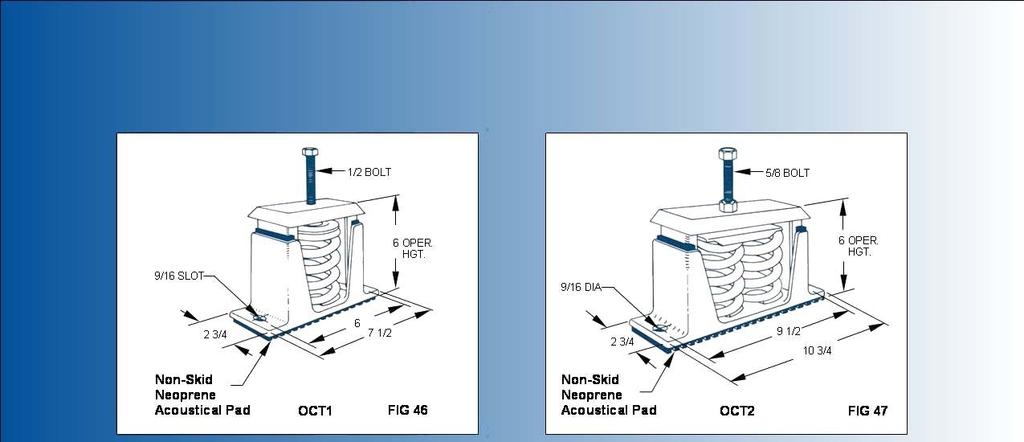
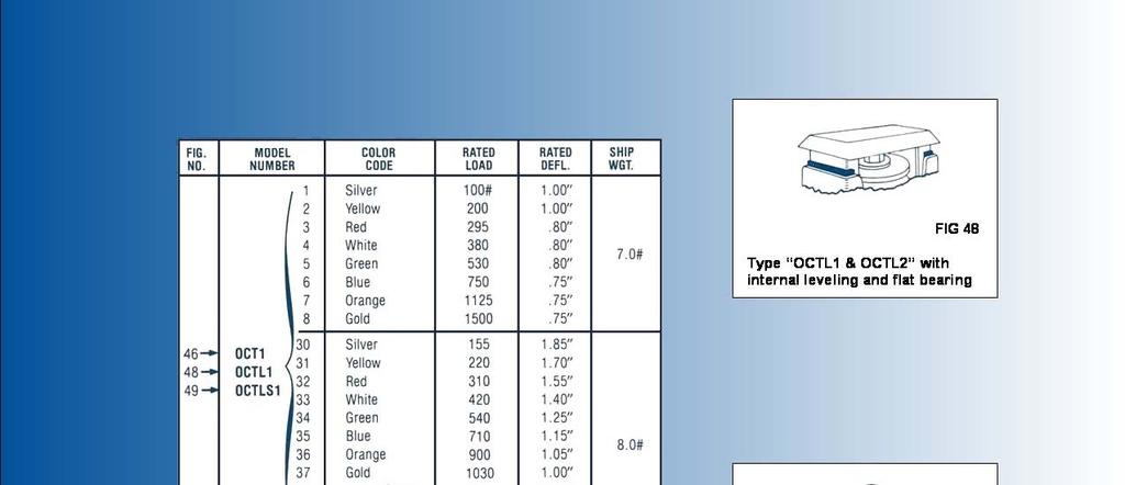
22 PLANNED ISOLATION: The isolation of machinery to prevent the transmission of vibration has become one of the important phases of modern plant engineering. Because concrete, steel, and other building materials are all good conductors of vibration, all mechanical equipment should be isolated. Properly planned isolation acts not only as a shield to prevent vibration transmission to the foundation, floor, the building structure and surrounding equipment, but it also materially reduces dynamic bearing loads. NOISE: With passage of the Noise Control Act of 97 and OSHA regulations which set limits to factory noise, it is important that all areas of noise reduction be considered. The use of a resilient medium between the equipment and structure acts to break the path of structural borne noise as well as noise resulting from sound waves that are magnified by the "sounding board" effect associated with machinery mounted solidly to the structure. Use of isolation does not reduce air borne noise which if found to be above allowable levels must be treated acoustically with acoustic enclosures or other sound absorbing devices. SHEAR MOUNTS: Elastomer-in-shear mounts provide up to /" static deflection. When assembled in series double deflection to /" is attained. By varying the durometer (hardness) of the elastomer elements or by assembling them in parallel, unlimited load capacity is attainable. Elastomer-in-shear isolators are available in unit, rail or integral base form and are commonly used to isolate a variety of machinery whose predominant disturbance is due to steady state uniform vibrations above 6 cpm. METAL SPRINGS: Metal springs become preferable when the required static deflections exceed /". Springs are highly efficient mechanical vibration absorbers and their lack of inherent damping and sound absorbing qualities may be readily overcome by the application of properly designed damping and sound absorbing materials. The use of spring devices for large deflections dictates the incorporation of leveling bolts in order to facilitate installation and to compensate for variations in deflection. Spring isolators are usually available either housed or free standing. Free standing springs are unrestrained devices which must be stable, i.e., where the ratio of the lateral to the axial spring constants is approximately equal; or where the outside spring diameter is at least.8 of the spring operating height. Housed springs vary in design and can be furnished with vertical and/or lateral restraints depending on the application. They are usually preferred over unhoused springs for in-plant installation. Springs are excellent isolators for both steady state vibrations and for impact. Typical equipment isolated for vibration are: Blowers Air Handling Units Pumps DONT'S for machine isolation Don t make a bouncing ball out of your machine. It's important that isolation be just right, not too hard nor too soft. At one point in it's softness resonance develops and with plenty of trouble. Don t ignore uneven weight distribution. If you do, the isolation will compress unevenly and the machine will tip. Excessive tipping or rocking may lead to serious trouble.

23
24 TERMS and DEFINITIONS AHP or Air Horsepower, is work done by the fan expressed as horsepower. CFM X TP AHP = 66 BHP or Brake Horsepower, is the horsepower absorbed by the fan. CFM or Cubic Feet Per Minute, is the volume of air moved per minute. Free Delivery is the condition under which a fan operates when no static pressure is present. HP or Horsepower, is the actual rated output of the fan motor used. ME or Mechanical Efficiency, is the ratio of horsepower absorbed (BHP) to horsepower delivered by the fan (AHP). AHP ME = BHP Standard Air is air which weighs.7 pounds per cubic foot, which is dry air at 7 F. dry bulb with a barometric pressure of 9.9 inches of mercury. SE. or Static Efficiency, is expressed as: CFM X SP SE = 66 X BHP SP or Static Pressure, is a measure of the force exerted by the fan in moving air through any ventilating system. TS or Tip Speed, is the peripheral speed in feet per minute of a propeller tip at any specified. TE or Total Efficiency, may be expressed as: CFM X TP TE = 66 X BHP VP or Velocity Pressure, is equal to the kinetic energy per unit of volume of the flowing air. It can be calculated from the formula FPM VP = TP or Total Pressure, is the sum of the static pressure (SP), and the velocity pressure (VP) at any given point in a ventilating system. FAN LAWS and FORMULAE used in Performance Calculations Fan efficiencies remain constant for symmetrical design. When one or more conditions change, the other conditions vary accordingly to certain fan laws for an established fan size, system of ductwork and air density. When fan speed is varied:. Fan's air-delivery will vary directly as the ratio. CFM = (CFM ). Developed fan pressures will vary as the ratio squared. SP = (SP ). Horsepower absorbed by fan will vary as the ratio cubed. HP = (HP ) When fan pressure varies:. Fan's air-delivery and will vary as the square root of the pressure ratio.. Horsepower absorbed by fan will vary as the square root of the pressure ratio cubed. When density of air varies:. For constant pressure fan speed, air delivery, and horsepower absorbed vary inversely as the square root of the density.. For constant air-delivery and fan speed-horsepower absorbed by fan and pressure developed vary directly as the air density.. For constant amount of air by weight-air-delivery, fan speed and developed pressure vary inversely as the density ratio.. For constant amount of air by weight-horsepower absorbed by fan varies inversely as the square of the density ratio. MOTOR DATA Unless otherwise specified, all motors furnished on Midwest Air Products fans are ball bearing and can be used in either horizontal or vertical positions. Totally enclosed non-ventilated, totally enclosed fan cooled, or explosion proof motors are available for belt driven units used for special applications. Many other special applications such as acid-proof, marine duty, outdoor weather-proof, chemical plant type, and vapor proof units are also available. Premium Efficiency motors and two -speed motors are available upon request. Area of a circle =.78 x (Dia.) CFM/ Area = FPM FPM x Area = CFM CFM/ FPM = Area


25 Highest Value Exhaust and Pollution Control Equipment Corrosion Resistant PVC Duct Corzan TM Duct Fiberglass Overlaid Duct Turnkey Installations and the Corzan TM Duct beat goes on Motorized Dampers Terminator TM Composite Mesh Pad Exhaust Hoods
PRESSURE BLOWERS. Capacities to 5,200 CFM Two wheel choices. Static pressures to 58 WG Temperatures to 600 F.
 BULLETIN 451 MARCH, 2014 PRESSURE BLOWERS Capacities to 5,200 Two wheel choices Static pressures to 58 WG Temperatures to 600 F. THE NEW YORK BLOWER COMPANY 7660 Quincy Street Willowbrook, IL 60527-55
INLET BOXES AND INLET-BOX DAMPERS
 INLET BOXES AND INLET-BOX DAMPERS Available on these Arrangement 1, 4, 8, 9, 9F, and 10 fans: GENERAL PURPOSE FANS ACOUSTAFOIL/PLR FANS CLASS IV FANS AF FANS RTS FANS GI FANS HPBC FANS BC FANS BCPB FANS
BULLETIN 456. July 1997 VANEAXIAL FANS. Type W Direct Drive/Belt Driven. Model VW Direct Drive. Model VWBD Belt Driven
 BULLETIN 456 July 1997 VANEAXIAL FANS Type W Direct Drive/Belt Driven Model VW Direct Drive Model VWBD Belt Driven Aerovent certifies that the Type W Vaneaxial Fans shown herein are licensed to bear the
VANEAXIAL & TUBEAXIAL FANS
 BULLETIN 482 July 2008 VANEAXIAL & TUBEAXIAL FANS Type "S" Belt Driven Featuring Welded Steel Propellers Models VSBD & TSBD Model TSBD Belt Driven Tubeaxial Type "S" Vaneaxial & Tubeaxial Fans For applications
Bulletin BCF 103 DESIGN 10A BACKWARD INCLINED WHEELS
 Bulletin BCF 10 DESIGN 10A BACKWARD INCLINED WHEELS Proven Reliability in Industrial Environments and Corrosive Atmospheres Design 10A s with Backward Inclined Wheels Chicago s Design 10A is a rugged multi-purpose
PRESSURE BLOWERS. Capacities to 5,200 CFM Two wheel choices. Static pressures to 58 WG Temperatures to 600 F.
 BULLETIN 451 SEPTEMBER, 2011 PRESSURE BLOWERS Capacities to 5,200 Two wheel choices Static pressures to 58 WG Temperatures to 600 F. THE NEW YORK BLOWER COMPANY 7660 Quincy Street Willowbrook, IL 60527-55
VANEAXIAL FANS. DUCT FANS Capacities to 60,000 CFM Static pressures to 2 WG. TUBEAXIAL FANS Capacities to 86,000 CFM Static pressures to 3 WG
 BULLETIN 671 AUGUST, 2016 VANEAXIAL FANS DUCT FANS Capacities to 60,000 Static pressures to 2 WG TUBEAXIAL FANS Capacities to 86,000 Static pressures to 3 WG Capacities to 0,000 Static pressures to 5 WG
FRP Fans: CLUB Series Performance and Technical Information
 FRP Fans: CLUB Series 1500-7300 Performance and Technical Information Verantis Environmental Solutions Group provides solutions for most common and complex situations including repair, rebuilding, field
SURGE LIMITING PB FANS. Designed for high pressure, low flow applications with stringent job process requirements
 SURGE LIMITING BULLETIN 485 APRIL, 2017 PB FANS Designed for high pressure, low flow applications with stringent job process requirements Capacities to 30,000 CFM Static pressures to 180 WG Temperatures
Twin City Fan & Blower
 Twin City Fan & Blower BULLETIN AX100-A October 2008 AXIFAN VANEAXIAL FANS TYPE TCVA TCVA Vaneaxial Fans The heart of the TCVA AXIFAN fan lies in its wheel. Cast of high strength aluminum alloy, the one-piece
Defining Innovation. backward curved FANs
 Defining Innovation. high efficiency industrial backward curved FANs TYPE HIB BULLETIN 00-B May 20 HIB High-Efficiency Industrial Backward-Curved Fans Model HIB fans from Twin City Fan & Blower employ
Fixed Pitch Vane Axial Fan
 Fixed Pitch Vane Axial Fan Page Introduction...........................................2 Construction Features...................................3 Mounting Options.......................................3
AXIFAN VANEAXIAL FANS
 Twin City Fan INDUSTRIAL PROCESS AND COMMERCIAL VENTILATION SYSTEMS AXIFAN VANEAXIAL FANS MODEL TCVA CATALOG AX100 JUNE 2013 VANEAXIAL FANS Model TCVA The heart of the TCVA AXIFAN fan lies in its wheel.
SECTION CENTRIFUGAL HVAC FANS
 SECTION 233416 - CENTRIFUGAL HVAC FANS 1. PART 1 GENERAL 1.1. RELATED DOCUMENTS A. Drawings and general provisions of the Contract, including General and Supplementary Conditions and Division 01 Specification
UTILITY BLOWERS. Models: BIUB / BIUBR / BIUBSH BAUB / DFC / FCUB. The Industrial Choice.
 UTILITY BLOWERS Models: BIUB / BIUBR / BIUBSH BAUB / DFC / FCUB The Industrial Choice. CATALOG 760 April 2017 Utility Blowers Overview Utility Blowers Aerovent s line of utility blowers is one of the most
CENTAXIAL TUBULAR CENTRIFUGAL FANS. BIA Airfoil Blade Design Direct Drive & Belt Driven Model CBD / CDD (Class I, II & III) Model CBD Belt Driven
 Model CBD Belt Driven") Model CBD Belt Driven Model CDD Direct Drive CENTAXIAL TUBULAR CENTRIFUGAL FANS BIA Airfoil Blade Design Direct Drive & Belt Driven Model CBD / CDD (Class I, II & III) CATALOG 337 February 2004 Centaxial
Model CBD Belt Driven Model CDD Direct Drive CENTAXIAL TUBULAR CENTRIFUGAL FANS BIA Airfoil Blade Design Direct Drive & Belt Driven Model CBD / CDD (Class I, II & III) CATALOG 337 February 2004 Centaxial
Tube Axial Fan Page Specifications & Dimension Data Performance Data
 Tube Axial Fan Page Introduction........................................... 2 Construction Features................................... 3 Information........................................... 4 Specifications
The Industrial Choice. Model VB Direct Drive. Model VBBD Belt Driven VANEAXIAL FANS. Direct Drive & Belt Driven Model VB / VBBD
 The Industrial Choice. Model VB Direct Drive Model VBBD Belt Driven VANEAXIAL FANS Direct Drive & Belt Driven Model VB / VBBD BULLETIN 466 November 2000 Contents Construction Features Belt Driven... 3
SECTION AXIAL HVAC FANS
 SECTION 233413 - AXIAL HVAC FANS 1. PART 1 GENERAL 1.1. RELATED DOCUMENTS A. Drawings and general provisions of the Contract, including General and Supplementary Conditions and Division 01 Specification
Series 8500 Centrifugal Swingout Fans Design 8510 Centrifugal Airfoil Design 8520 Centrifugal BI
 Bulletin 8510-4 May 2000 Series 8500 Centrifugal Swingout Fans Design 8510 Centrifugal Airfoil Design 8520 Centrifugal BI Description Index Series 8500 Centrifugal Swingout Fans The Series 8500 Centrifugal
VERANTIS. FRP Fans: CMHB Series Performance and Technical Information. Environmental Solutions Group
 VERANTIS Environmental Solutions Group FRP Fans: CMHB Series 6-8-10 Performance and Technical Information Bulletin 11-6 Rev May 2013 VERANTIS Environmental Solutions Group Verantis Environmental Solutions
General TAHVIEH HAMOON Airfoil Centrifugal Fans Utilize the latest design techniques to product a quiet highly efficient air mover.
 General TAHVIEH HAMOON Airfoil Centrifugal Fans Utilize the latest design techniques to product a quiet highly efficient air mover. Aerodynamically designed blades and air passages allow more air to be
ARRANGEMENT 4/4F/4H/4V SINGLE-WIDTH ACOUSTAFOIL/PLR FANS
 ARRANGEMENT 4/4F/4H/4V SINGLE-WIDTH ACOUSTAFOIL/PLR FANS 13 Class PLR Arr. 4 Fan, CW rotation with top angular up discharge. APPLICATIONS With three classes to choose from, the Arrangement 4/4F/4H/4V Single-Width
Tubular Centrifugal Inline Fans Page Introduction... 2 Construction Features... 3 Specification and Dimension Data TCN-D (Inline Fan- Direct
 Tubular Centrifugal Inline Fans Page Introduction........................................... 2 Construction Features.................................. 3 Specification and Dimension Data TCN-D (Inline Fan-
Vaneaxial Fans. Series 25 Series 53 Series 53C Series 54 Series 55 HARTZELL. Hartzell Fan, Inc., Piqua, Ohio
 Vaneaxial Fans Series 25 Series 53 Series 53C Series 54 Series 55 BUILT WITH HONOR HARTZELL FAN, INC PIQUA, OHIO USA HARTZELL Hartzell Fan, Inc., Piqua, Ohio 45356 February 2008 Index Model Code Explanation...Page
Turning Air Into Solutions. PLUG FANS TYPE BCPL
 Turning Air Into Solutions. PLUG FANS TYPE BCPL CATALOG 350 December 2009 BCPL Plug Fans BCPL plug fans from Twin City Fan & Blower are compact and versatile. Their versatility allows them to be used for
TYPE HP. Static pressures to 128 WG Capacities to 20,000 CFM Temperatures to 600 F. PRESSURE BLOWERS Static pressures to 58 WG Capacities to 5,200 CFM
 BULLETIN 1 JANUARY, 20 TYPE HP PRESSURE BLOWERS PRESSURE BLOWERS Static pressures to 5 WG Capacities to 5,200 CFM Static pressures to WG Capacities to 20,000 CFM Temperatures to 00 F. THE NEW YORK BLOWER
Defining Innovation. radial tip FaNS type Hrt BULLETIN 980 October 2009
 Defining Innovation. radial tip FANS TYPE HRT BULLETIN 980 October 2009 HRT Radial Tip Fans Twin City Fan & Blower s Type HRT Industrial Duty Radial Tip Fan line is engineered for higher specific speeds.
TURNING AIR INTO SOLUTIONS. UTILITY SETS DCV BCV BCVR BCVSH BAV DDF FCV
 TURNING AIR INTO SOLUTIONS. UTILITY SETS DCV BCV BCVR BCVSH BAV DDF FCV CATALOG 600 March 2017 UTILITY SETS Model DCV Overview Utility Sets Twin City Fan s line of utility ventilating sets is one of the
SQBI BLOWERS BACKWARD INCLINED CLASS II CLASS IIP CLASS III. OEM and Industrial Air Handling Specialist
 OEM and Industrial Air Handling Specialist SQBI BLOWERS BACKWARD INCLINED CLASS II CLASS IIP CLASS III 7697 Snider Road, Mason, OH 4040-913 Telephone: 13-73-0600 Visit us at www.cincinnatifan.com for more
TUBULAR CENTRIFUGAL INLINE FANS
 Twin City Fan INDUSTRIAL PROCESS AND COMMERCIAL VENTILATION SYSTEMS TUBULAR CENTRIFUGAL INLINE FANS MODEL TSL CATALOG 1001 APRIL 2014 CENTRIFUGAL INLINE FANS Model TSL The TSL is an inline centrifugal
Fiberglass Axial Flow Fans. Series 28 Series 28B. Series 34 Series 35 Series 35V. Series 29 Series 29B HARTZELL
 Fiberglass Axial Flow Fans Series 28 Series 28B Series 29 Series 29B Series 34 Series Series V BUILT WITH HONOR HARTZELL FAN, INC PIQUA, OHIO USA HARTZELL Hartzell Fan, Inc., Piqua, Ohio 46 Bulletin A-39-N
Turning Air Into Solutions. AXIFAN VANEAXIAL & TUBEAXIAL FANS TCVS/TCTS TCVSSH/TCTSSH
 Turning ir Into Solutions. XIFN VNEXIL & TUBEXIL FNS TCVS/TCTS TCVSSH/TCTSSH CTLOG X250 May 2012 Vaneaxial&TubeaxialFans Models TCVS I TCTS I TCVSSH I TCTSSH For applications requiring extensive corrosion
Twin City Fan & Blower
 Twin City Fan & Blower BULLETIN 370 January 2007 AIRFOIL FANS TYPE BAE SWSI and DWDI BAE SWSI and DWDI Airfoil Fans Featuring the E-Series Wheel This catalog features the new BAE airfoil wheel design.
Turbo Pressure Blowers
 www.americanfan.com Bulletin VP4 Turbo Pressure Blowers Howden Industrial Fan Group American Fan / Joy Fan / Garden City Fan Features Heavy gauge continuously welded housings, reversible and rotatable
Air Moving Solutions. axifan adjustable blade vaneaxial fans
 Air Moving Solutions. axifan adjustable blade vaneaxial fans MODEL TCVX CATALOG AX300 December 2012 VaneaxialFans Model TCVX The heart of the TCVX AXIFAN lies in its wheel. The manually adjustable blades
MARINE DUTY TUBEAXIAL & VANEAXIAL FANS
 BULLETIN 420 November 2000 MARINE DUTY TUBEAXIAL & VANEAXIAL FANS Type MD Direct Drive Model MDTM, MDVM & MDVH Marine Duty Tubeaxial and Vaneaxial Fans Aerovent s Marine Duty Fans feature medium and high
The Industrial Choice. Model VJ Direct Drive MANUALLY ADJUSTABLE-AT-REST VANEAXIAL FANS. Direct Drive & Belt Driven Model VJ / VJBD
 The Industrial Choice. Model VJ Direct Drive MANUALLY ADJUSTABLE-AT-REST VANEAXIAL FANS Direct Drive & Belt Driven Model VJ / VJBD CATALOG 476 June 2015 Vaneaxial Fans Model VJ / VJBD Type "J" The heart
SQAF AIRFOIL BLOWERS CLASS IP CLASS II CLASS IIP CLASS III. OEM and Industrial Air Handling Specialist
 OEM and Industrial Air Handling Specialist SQAF AIRFOIL BLOWERS CLASS IP CLASS II CLASS IIP CLASS III 69 Snider Road, Mason, OH 4040-913 Telephone: 13-3-0600 Visit us at www.cincinnatifan.com for more
Bulletin ACF 103 AIRFOIL CENTRIFUGAL FANS DESIGN 10A
 Bulletin ACF 103 AIRFOIL CENTRIFUGAL FANS DESIGN 10A Quieter, More Efficient Airfoil Fans for Commercial and Light Industrial Applications Design 10A Fans with Airfoil Wheels Fourteen Sizes to 80" Volumes
Air Moving Solutions. low pressure mixed flow fans. QCLB QCLBR (Restaurant) QCLBSH (Smoke & Heat)
 QCLBSH (Smoke & Heat)") Air Moving Solutions. low pressure mixed flow fans QCLB QCLBR (Restaurant) QCLBSH (Smoke & Heat) BULLETIN 1070 February 2012 MixedFlowFans Models QCLB QCLBR QCLBSH Benefits of Mixed Flow Fans Twin City
Air Moving Solutions. low pressure mixed flow fans QCLB QCLBR (Restaurant) QCLBSH (Smoke & Heat) BULLETIN 1070 February 2012 MixedFlowFans Models QCLB QCLBR QCLBSH Benefits of Mixed Flow Fans Twin City
OEM and Industrial Air Handling Specialist Snider Road, Mason, OH Telephone:
 HDBI BLOWERS OEM and Industrial Air Handling Specialist BACKWARD INCLINED CLASS II CLASS III CLASS IV 797 Snider Road, Mason, OH 45040-915 Telephone: 51-57-000 Visit us at www.cincinnatifan.com for more
Good Enough Never Is. Plug Fan SERIES 12
 Plug Fan SERIES 12 Good Enough Never Is The Hartzell Difference Combine Hartzell QUALITY with your PRODUCT for a BETTER CHOICE for your customers! GOOD ENOUGH NEVER IS. Hartzell Air Movement is the industrial
Twin City Fan & Blower
 BULLETIN 600 Twin City Fan & Blower September 2009 VENTILATING SETS TYPE BCV (Backward Inclined) TYPE BCVU5 (UL 705 Listed) TYPE BCVU2 (UL 762 Listed) TYPE BCVSH (UL Smoke & Heat) TYPE BAV (Airfoil) TYPE
Defining Innovation. turbo pressure blowers. Twin City Catalog 1200
 Defining Innovation. turbo pressure blowers MODEL TBA TBR 1 Twin City Catalog CATALOG -A May 11 Model TBA/TBR Turbo Pressure Blowers Model TBA and TBR fans from Twin City Fan & Blower are constant pressure,
TURBO PRESSURE BLOWERS
 Twin City Fan INDUSTRIAL PROCESS AND COMMERCIAL VENTILATION SYSTEMS TURBO PRESSURE BLOWERS TBA TBR CATALOG 10 APRIL 13 TURBO PRESSURE BLOWERS Models TBA TBR TBR Arrangement 8 Model TBA and TBR fans from
TUBEAXIAL PAINT SPRAY BOOTH EXHAUST FANS
 Twin City Fan INDUSTRIAL PROCESS AND COMMERCIAL VENTILATION SYSTEMS TUBEAXIAL PAINT SPRAY BOOTH EXHAUST S MODEL TCBS CATALOG AX220 MAY 2013 TUBEAXIAL S Model TCBS The Twin City Fan & Blower model TCBS
Air Moving Solutions. AIRFOIL fans
 Air Moving Solutions. AIRFOIL fans BAE SWSI BAE DWDI CATALOG 370 December 2012 AirfoilFans Models BAE SWSI & BAE DWDI Featuring the E-Series Wheel This catalog features the new BAE airfoil wheel design.
Centrifugal Utility Fans - SFD/SFB
 C H F D B G E A Centrifugal Utility Fans - SFD/SFB SFB STANDARD CONSTRUCTION FEATURES HOUSING: Heavy gauge steel housing with Lock-seam construction Unit support angles with prepunched mounting holes Adjustable
Bulletin VX05 VANEAXIAL FANS
 Bulletin VX05 VANEAXIAL FANS Models: VXD, VXB Direct Drive and Belt Drive s VXD/VXB Introduction CERTIFIED RATINGS AMCA Certification UL Certification PennBarry certifi es that the Vaneaxial fans shown
Defining Innovation. high efficiency industrial AiRfoiL fan TyPe haf BULLETIN 1150 May 2011
 Defining Innovation. high efficiency INDUSTRIAL airfoil FAN TYPE HAF BULLETIN 1150 May 2011 HAF High Efficiency Industrial Airfoil Fans Model HAF fans from Twin City Fan & Blower employ a high efficiency
The Industrial Choice. Vane Section For Model VTBD. Model TTABD TUBEAXIAL & VANEAXIAL FANS. Type "T" Belt Driven Model TTABD / VTBD
 The Industrial Choice. Vane Section For Model VTBD Model TTABD TUBEAXIAL & VANEAXIAL S Type "T" Belt Driven Model TTABD / VTBD BULLETIN 424-A November 1998 Model TTABD/VTBD Tubeaxial/Vaneaxial Fans Aerovent
Square Inline Fans with Multi-Directional Discharge
 SQN Square Inline Fans with Multi-Directional Discharge Page Introduction............................................2 Standard Construction Features............................ 3 Specifications and Dimension
Inline and Roof Mounted Fans
 CV Inline and Roof Mounted Fans Page Introduction........................................... 2 Construction Features................................. 3-4 Specifications and Dimension Data CVD (Direct Drive
Air Moving Solutions. VENTILATING SETs BCV BCVU5 BCVU2 BCVSH BAV FCV
 Air Moving Solutions. VENTILATING SETs BCV BCVU5 BCVU2 BCVSH BAV FCV CATALOG 600 March 2012 VentilatingSets Models BCV BCVU5 BCVU2 BCVSH BAV FCV Twin City Fan s line of utility ventilating sets is one
PVC Ductwork
 1-800-21-77 www.midwestair.com PVC Ductwork wet scrubbers chrome (CMP) scrubbers mist eliminators (CMP) exhaust fans exhaust hoods canopy hoods ductwork installation maintenance programs custom fabrications
TURNING AIR INTO SOLUTIONS. COMMERCIAL DUTY PLENUM FANS EPLFN EPLQN
 TURNING AIR INTO SOLUTIONS. COMMERCIAL DUTY PLENUM FANS EPLFN EPLQN CATALOG 455 June 2014 PLENUM FANS Overview EPLFN I EPLQN Plenum fans are unhoused fans designed to operate inside of field-fabricated
Defining Innovation. mixed flow fans. TYPE QSL (Standard) QSLR (Restaurant) QSLSH (Smoke and Heat) QFE (Fume Hood Exhaust)
 QSLR (Restaurant) QSLSH (Smoke and Heat) QFE (Fume Hood Exhaust)") Defining Innovation. mixed flow fans TYPE QSL (Standard) QSLR (Restaurant) QSLSH (Smoke and Heat) QFE (Fume Hood Exhaust) BULLETIN 1060 February 2011 QSL Mixed Flow Fans Benefits of Mixed Flow Fans Twin
Defining Innovation. mixed flow fans TYPE QSL (Standard) QSLR (Restaurant) QSLSH (Smoke and Heat) QFE (Fume Hood Exhaust) BULLETIN 1060 February 2011 QSL Mixed Flow Fans Benefits of Mixed Flow Fans Twin
Twin City Fan & Blower
 Twin City Fan & Blower VENTILATING SETS TYPE BCV (Backward Inclined) TYPE BCVU5 (UL 705 Listed) TYPE BCVU2 (UL 762 Listed) TYPE BCVSH (UL Smoke & Heat) TYPE BAV (Airfoil) TYPE FCV (Forward Curved) Ventilating
COMMERCIAL DUTY PLENUM FANS
 Twin City Fan INDUSTRIAL PROCESS AND COMMERCIAL VENTILATION SYSTEMS COMMERCIAL DUTY PLENUM FANS EPLFN EPLQN CATALOG 455 JUNE 2014 PLENUM FANS Overview EPLFN I EPLQN Plenum fans are unhoused fans designed
& 12" 96" / TABD CATALOG
 The Industrial Choice. Model TA Direct Drive Model TABD Belt Driven TUBEAXIAL S Macheta Airfoil Design Direct Drive & Belt Driven Sizes 2" through 96" Models TA / TABD CATALOG 5 August 204 Tubeaxial Fans
INDUSTRIAL PROCESS AND COMMERCIAL VENTILATION SYSTEMS. Twin City Fan PRESSURE BLOWERS MODEL PBW CATALOG 1260 APRIL 2015
 Twin City Fan INDUSTRIAL PROCESS AND COMMERCIAL VENTILATION SYSTEMS PRESSURE BLOWERS MODEL PBW CATALOG 120 APRIL WWW.TCF.COM PRESSURE BLOWERS Overview Model PBW The PBW is designed for low flow and high
CAST ALUMINUM PRESSURE BLOWERS
 Twin City Fan INDUSTRIAL PROCESS AND COMMERCIAL VENTILATION SYSTEMS CAST ALUMINUM PRESSURE BLOWERS TPD TPB CATALOG 820 JANUARY 2013 PRESSURE BLOWERS Models TPD TPB Twin City Fan & Blower s Cast Aluminum
INDUSTRIAL PROCESS AND COMMERCIAL VENTILATION SYSTEMS. Twin City Fan RADIAL TIP FANS MODEL RTF CATALOG 950 AUGUST 2012
 Twin City Fan INDUSTRIAL PROCESS AND COMMERCIAL VENTILATION SYSTEMS RADIAL TIP FANS MODEL RTF CATALOG 950 AUGUST 2012 RADIAL TIP FANS Model RTF Model RTF radial tip fans are of a heavy duty, rugged design,
belt drive utility sets vent-pak series models vp-bi & fc january 2007 vp 1.07
 belt drive utility sets vent-pak series models vp-bi & fc january 2007 vp 1.07 model vp - belt drive utility set Application VENT-PAK fan wheels are the versatile, quiet, energy efficiency backward inclined
LOW PRESSURE MIXED FLOW FANS
 Twin City Fan INDUSTRIAL PROCESS AND COMMERCIAL VENTILATION SYSTEMS LOW PRESSURE MIXED FLOW FANS QCLB QCLBR QCLBSH CATALOG 1070 JANUARY 2017 MIXED FLOW FANS Models QCLB QCLBR QCLBSH QCLB (Horizontal) Benefits
A Fläkt Woods Company. Model PFB Panel Exhaust Fans 24" 72" Diameter Bulletin PF-1410 July 2003
 A Fläkt Woods Company PFB Panel Exhaust Fans 24" 72" Diameter Bulletin PF-1410 July 2003 Fläkt Woods Group Creative Air Fläkt Woods was created by bringing together several of the worlds leading players
DESIGN GUIDELINES FANS PAGE 1 of 7
 DESIGN GUIDELINES FANS PAGE 1 of 7 1.1. REFERENCE STANDARDS 1.1.1. Publications listed below (including amendments, addenda, revisions, supplements and errata) form a part of this specification to the
MODEL TUB TUBEAXIAL UPBLAST PROPELLER ROOF EXHAUSTER
 MODEL MODEL FEATURES Exhaust air up to 60,116 CFM in static pressure applications up to 1 w.g. Straight-through air flow design results in maximum exhaust efficiency Motor and drives are located outside
Centrifugal Plenum Fan
 PLC Loren Cook Company is proud to be the world leader of industrial and commercial fans and blowers. With a commitment of over 60 years, Loren Cook Company believes in superior quality and phenomenal
Twin City Fan & Blower
 Twin City Fan & Blower BULLETIN 300-F January 2009 BACWARD INCLINED FANS TYPE BC SWSI & DWDI BC SWSI & DWDI Backward Inclined Fans This catalog features type BC non-overloading centrifugal fans in SWSI
The Industrial Choice. Model SCDD Direct Drive. Model SCBD Belt Driven SQUARE INLINE FANS. Direct Drive & Belt Driven Model SCDD / SCBD
 The Industrial Choice. Model SCDD Direct Drive Model SCBD Belt Driven SQUARE INLINE FANS Direct Drive & Belt Driven Model SCDD / SCBD BULLETIN 40 January 007 Square Inline Centrifugal Fans General Information
Tubular Centrifugal Fans
 Tubular Centrifugal Fans Model TCB Inline - Horizontal or Vertical Roof Upblast and Roof Supply March 2007 Tubular Centrifugal Fans The TCB series of inline centrifugal fans is designed for ducted inline,
BACKWARD INCLINED BI AND BIA INDUSTRIAL SWSI CENTRIFUGAL FANS
 BLLEIN 71-D November 2004 BACKWARD INCLINED BI AND BIA INDSRIAL SWSI CENRIFGAL FANS BI Flat Blade Design BIA Airfoil Blade Design Class I, II, III, IV BI & BIA Industrial Centrifugal Fans Aerovent s BI
BELT DRIVE VANEAXIAL FIXED PITCH FANS
 BELT DRIVE VANEAXIAL FIXED PITH FANS BULLETIN 6 JANUARY, 01 apacities to 0,000 Static pressures to WG Temperatures to 00 F. THE NEW YORK BLOWER OMPANY 660 Quincy Street Willowbrook, IL 60-0 Visit us on
AF FANS HIGH-EFFICIENCY AIRFOIL. AF-30 FANS Capacities to 123,000 CFM Static pressures to 30 WG
 BULLETIN 331 JUNE, 2007 HIGH-EFFICIENCY IRFOIL F FNS F-30 FNS Capacities to 123,000 Static pressures to 30 WG F-40 FNS Capacities to 240,000 Static pressures to 46 WG THE NEW YORK BLOWER COMPNY 7660 Quincy
SARAVEL CENTRIFUGAL FANS For Airconditioning & Industrial Application
 CAT.NO. 120-97 SARAVEL CENTRIFUGAL FANS For Airconditioning & Industrial Application TABLE OF CONTENTS Introduction......3 Selection Examples......4-5 Correction Factors......6 Rating Tables.........7-17
North American Series 2300 Turbo Blowers 4-44 OSI & 55-11,500 CFM for standardized product 4-60 OSI, up to 100,000 CFM for custom product
 Combustion North American Series 2300 Turbo Blowers 4-44 OSI & 55-11,500 CFM for standardized product 4-60 OSI, up to 100,000 CFM for custom product FEATURES Direct drive blowers specifically for combustion
.3 Section Vibration Isolation and Seismic Control..2 ANSI/AMCA 210/ASHRAE 51 Laboratory Methods of Testing Fans for Rating.
 Issued 2005/06/01 Section 15831 Commercial Fans Page 1 of 6 PART 1 GENERAL 1.1 RELATED SECTIONS.1 Section 01355 Waste Management and Disposal..2 Section 15053 Motors, Drives and Guards..3 Section 15072
Twin City Fan & Blower
 Twin City Fan & Blower BULLETIN 4810 August 2005 PROPELLER WALL S DIRECT AND BELT DRIVE TYPE WPMD/WPMB WPMD/WPMB Propeller Wall Fans Twin City Fan & Blower WPMD and WPMB Medium Duty Propeller Wall Fans
SECTION HVAC POWER VENTILATORS
 SECTION 233423 HVAC POWER VENTILATORS 1. PART 1 GENERAL 1.1. RELATED DOCUMENTS A. Drawings and general provisions of the Contract, including General and Supplementary Conditions and Division 01 Specification
Centrifugal Filtered Supply Roof Blowers
 CFS Centrifugal Filtered Supply Roof Blowers Page Introduction...................................... 2 Specifications and Dimension Data................... 3 Typical Installation................................
VANEAXIAL FIXED PITCH FANS
 VANEAXIAL FIXED PITH FANS BULLETIN 6 DEEMBER, 0 apacities to 0,000 Static pressures to WG Temperatures to 00 F. THE NEW YORK BLOWER OMPANY 660 Quincy Street Willowbrook, IL 60-0 Visit us on the Web: http://www.nyb.com
TURBO PRESSURE BLOWERS
 Twin City Fan INUSTRIAL PROCESS AN COMMERCIAL VENTILATION SYSTEMS TURBO PRESSURE BLOWERS TBNA TBNS CATALOG 12 AUGUST 14 TURBO PRESSURE BLOWERS Overview TBNA I TBNS The TBN series of fans are low volume,
SQUARE INLINE CENTRIFUGAL FANS
 Twin City Fan INDUSTRIAL PROCESS AND COMMERCIAL VENTILATION SYSTEMS SQUARE INLINE CENTRIFUGAL FANS DSI BSI CATALOG 40 FEBRUARY 07 SQUARE INLINE CENTRIFUGAL FANS Overview DSI BSI Twin City Fan & Blower
MODEL TUB TUBEAXIAL UPBLAST PROPELLER ROOF EXHAUSTER
 MODEL TUB MODEL FEATURES Exhaust air up to 60,116 CFM in static pressure applications up to 1 w.g. Straight-through air flow design results in maximum exhaust efficiency Motor and drives are located outside
BAC, BAF, BAH Central Station Air Handlers
 PRODUCT DATA & INSTALLATION Bulletin B80-BA-PDI-5 Part # 1097717 PRODUCT SUPPORT web: b-rp.ca/bah email: ahu@b-rp.ca call: 1-844-893-3222 x527 scan: BAC, BAF, BAH Central Station Air Handlers Indoor and
Centrifugal Roof Supply Fans Models RSF and RSFP. Forward Curved
 Centrifugal Roof Supply Fans Models and Forward Curved April 2008 Centrifugal Filtered Roof Supply Fan When you buy a Greenheck model or, you receive a fan with the industry s best performance and durability
Air Moving Solutions. MODULAR plenum fans
 Air Moving Solutions. MODULAR plenum fans MPQN MPQS CATALOG 490 March 2012 PlenumFans Models MPQN MPQS The MPQN and MPQS offer many of the same advantages of the venerable EPQN plenum fan. The MPQN and
INLINE CENTRIFUGAL DUCT FANS Direct and Belt Driven Models ZIDK and ZIBK
 INLINE CENTRIFUGAL DUCT FANS Direct and Belt Driven Models ZIDK and ZIBK DESIGNED AND ENGINEERED TO MEET INDUSTRY NEEDS Air Zoë Centrifugal Inline Duct fans have been developed to efficiently handle the
Turning Air Into Solutions. CAST ALUMINUM PRESSURE BLOWERS MODEL TPD MODEL TPB
 Turning Air Into Solutions. CAST ALUMINUM PRESSURE BLOWERS MODEL TPD MODEL TPB CATALOG 820 January 2013 PressureBlowers Models TPD TPB Twin City Fan & Blower s Cast Aluminum Pressure Blowers are the perfect
Filtered Kitchen Supply Packaged Ventilator
 Filtered Kitchen Supply Packaged Ventilator Page Introduction........................................... 2 Information............................................ 3 Specifications and Dimension Data KD................................................
MODEL CTB TUBULAR CENTRIFUGAL INLINE BELT DRIVEN FAN
 MODEL FEATURES Rated up to 20,000 CFM in static pressure applications up to 2-1/2 w.g. Motor drives are located outside of the airstream Ideal for applications where space is limited Belt drives permit
Tube Axial Inline Fans
 Tube Axial Inline Fans Models TDI & TBI-CA Level 3 with Cast Aluminum Propeller Direct & Belt Drive Clean Air or Fume Exhaust July 2011 Features Tube Axial Inline Fans Greenheck s tube axial fans are the
Centrifugal Roof Supply Fans Models RSF and RSFP. Forward Curved
 Centrifugal Roof Supply Fans Models and Forward Curved B U I L D I N G V A L U E I N A I R. April 2008 Centrifugal Filtered Roof Supply Fan When you buy a Greenheck model or, you receive a fan with the
Mixed Flow Inline Fan, Model MFSI
 Mixed Flow Inline Fan, Model MFSI TABLE OF CONTENTS 3 Introduction, Certifications & Listings 4 Features & Benefits 5 Options & Accessories 6 Dimensional Data 10 Performance Data 27 Sound Data 44 Engineering
to meet the updated test procedures outlined in the 1974 AMCA test code.
 Sheldons Engineering is a long-standing member of AMCA The Air Movement and Control Association which acts as an independent association for fan manufacturers. As you may be aware, Sheldons Engineering
BULLETIN 912-A. February 1999 HIGH PRESSURE BLOWER. Model HPB Direct Drive/Belt Driven
 BULLETIN 912-A February 1999 HIGH PRESSURE BLOWER Model HPB Direct Drive/Belt Driven Model HPB High Pressure Blowers Aerovent s High Pressure Blowers feature high static pressure capabilities from 11"
Axial Propeller Panel Fans, PAF-Series
 Axial Propeller Panel Fans, PAF-Series TABLE OF CONTENTS 3 Introduction 4 Certifications & Listings 4 Options & Accessories 9 Motor Availability 11 Direct Drive Dimensional & Performance Data 14 Belt Drive
TURNING AIR INTO SOLUTIONS. AIR KITS. Model FC
 TURNING AIR INTO SOLUTIONS. AIR KITS Model FC CATALOG 150 June 2017 AIR KITS Overview FC Wheel Construction Air kit wheels are designed for speeds up to 7,000 ft/min. at 70 F. The blades are die-formed