to meet the updated test procedures outlined in the 1974 AMCA test code.
|
|
|
- Roxanne Bruce
- 6 years ago
- Views:
Transcription


1
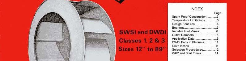
2 Sheldons Engineering is a long-standing member of AMCA The Air Movement and Control Association which acts as an independent association for fan manufacturers. As you may be aware, Sheldons Engineering has manufactured fans for over 100 years. Our product offering includes standard centrifugal and axial fans as well as custom manufactured units to meet our customers requirements. Our fans are used in applications requiring up to 80 wg static pressure and flows from 500-1,000,000 cfm. Our web site at contains all of these notes for your reference. We would list our complete product offering, but Sheldons is and has always been a custom manufacturer. Please contact us to discuss your application. Sheldons Engineering has realized the need for more detailed information to be provided for the selection of fans, particularly the effect of appurtenances and site conditions on the fan performance in the field. Since site conditions seldom approach laboratory conditions, it is necessary to make some practical allowance for the effect of site conditions on fan ratings. Therefore, in this catalog, Sheldons have attempted to provide the Consulting Engineer and end user with practical guide lines to assist in arriving at a fan selection that is reasonably valid for the particular application, taking into account the many variables that have been found to affect fan performance in the field. Further detailed information on these effects can be found in AMCA Publications 201, 202 and 203. ENERGY CONSERVATION System designs today demand more accurate estimates of energy consumption. By considering all the factors affecting fan performance shown in this catalog, and applying all the losses involved, the consulting engineer and end user are provided with all the information to make an accurate determination of fan horsepower, resulting in valuable savings. The AMCA seal as shown below is a guarantee of performance resulting from a rigorous test program undertaken in accordance with AMCA Standard Sheldons modern Research and Development facility, a fully approved AMCA test laboratory, was completely reequipped to meet the updated test procedures outlined in the 1974 AMCA test code. AMCA CERTIFIED RATINGS Because of variation of performance with size, it is not practical to rate all fan sizes from a single fan test. There fore, in order to provide optimum performance, especially in the smaller sizes, Sheldons have tested 5 basic fan sizes, both SWSl and DWDI. These tested fans are then rated up to larger sizes and presented according to the requirements of AMCA Publication 211 for air performance, to provide conservative ratings. To ensure integrity of ratings, AMCA requires that published fan performance data clearly state the basis from which the ratings were obtained, and any limitations noted. In addition, rigorous check testing of random fan sizes and speeds, are made regularly by AMCA staff to ensure published ratings are being met by production fans. Sheldons certifies that the Type UNF Unifoil and Type ULF Ultrafoil Centrifugal fans shown herein are licensed to bear the AMCA Seal, The ratings shown are based on tests made in accordance with AMCA Standard 210, and comply with the requirements of the AMCA Certified Ratings Program. The AMCA Certified Ratings Seal applies to air capacities only AMCA CLASS LIMITS In accordance with AMCA Standard , the class operating limits have been defined at certain outlet velocities and static pressures. Values beyond these limits can be published but the class limits must be capable of being met by the class of the fan. With most fan manufacturers, the upper and lower limits of the class range are met at two slightly different speeds, and in this case, the higher speed will determine the fan design capability. The class limitation line shown on each fan-rating curve has been drawn at this higher speed. It is suggested that when a required performance lies at a speed 5% less than the class limit, then the next higher fan class be chosen. In this way, slight increases in fan speed to suit site conditions will not put the fan beyond the class design limit. In this catalog Sheldons provide standard information in Class 1, 2 and 3 fans, both single width and double width. For larger or heavier duty fans for extra heavy-duty commercial or industrial applications, consult Sheldons nearest sales office. 2
3 SOUND Overall sound power levels in eight octave bands have been calculated for the speed range covered in each fan size, and are shown in a table on each performance curve for the area of maximum efficiency. For other speeds simple interpolation between the given speeds is quite satisfactory. Sound levels vary slightly with the point of operation and may be approximately compensated for by further addition of the db values noted in the zones defined by the radial lines on each performance-rating curve. When calculating sound levels in either inlet or outlet ductwork, deduct 3 db from the overall sound power levels to arrive at sound power levels at the fan inlet or outlet. Sound pressure levels must be calculated from information available to the system designer or end user, using room absorption effects. Sound pressure levels in typical equipment rooms, can generally be estimated by Sheldons from their field tests on comparable applications. SPARK-RESISTANT CONSTRUCTION For fans handling potentially explosive mixtures, AMCA standard sparkproof construction is available in Arr. 1, Arr. 2, Arr. 4, Arr. 8 and Arr. 9 only. Bearings are not located in the gas stream. There are three classifications of construction as follows: Type A - "All parts of the fan in the air or gas being handled shall be made of non-ferrous material." Aluminum wheel, housing and inlet, with monel shaft. All other parts are standard steel construction. (Generally limited to Class 2 and/or 250 F.) Type B - "Fan shall have an entirely non-ferrous wheel and non-ferrous ring about the opening through which the shaft passes." Aluminum wheel and aluminum disc where the shaft passes through fan case. All other parts are standard steel construction. (Generally limited to Class 2 and/or 250 F.) Type C - "Fan shall be so constructed that a shift of the wheel or shaft will not permit two ferrous parts to rub or strike." Aluminum inlet and aluminum disc where the shaft passes through the fan case. All other parts are standard steel construction. (Generally limited to 500 F. operation). Temperature Limitations Air or Gas Temp F Arr 1 & 9 Arr 3 % of Max Speed Limit Up to 130 F Standard Bearings Standard Bearings 100% F Standard Bearings Not Applicable 94% F Above 300 F Standard Bearings w/ cooling disc Not Applicable 89% Consult Sheldons Engineering Arrangements 3


4 FEATURES Streamlined lnlet Cone lnlet spinnings are designed for the smooth acceleration of airflow into the wheel, with clearances designed to maintain efficiency and reduce noise to a minimum. On smaller sizes in Classes 1 and 2, an inlet collar is provided for duct connection. On sizes 402 and above, a rectangular flange on the fan case provides connection to ductwork. Bearing Pedestals Heavy-duty bearing pedestals of structural steel with extra stiffeners on Class 3 fans, maintain accurate alignment, prevent distortion due to belt pull, and provide minimum resistance to the airflow. For actual effect of bearing in the air stream on the performance of Arr. 3 fans, see note on fan performance curves on page 5. Shafts Shafts are ground or machined to close tolerances to ensure accurate fits with bearings and hub. Shafts are designed to accommodate at least a 5% increase in speed over the maximum speed for each class limit. All hubs are keyed to the shaft. Housing Fabricated from heavy gauge steel, continuously welded for strength and air-tight construction. Heavy angle reinforcement on the fan case increases the stiffness and provides support for the bearing pedestals on large fans. In many instances, fan housings size 660 and larger, must be split and shipped knocked-down due to their size and configuration. Wheel Type ULF Ultrafoil wheels have double-thickness airfoil blades, accurately die-formed and jig welded to ensure consistent profile to maintain maximum design efficiency. Type UNF Unifoil wheels have single-thickness airfoil blades, accurately die-formed and jig welded to the shroud and back plate. Reinforcing rings are added a t higher tip speeds. All wheels have heavy-duty cast iron or aluminum hubs. Shrouds are formed from a one piece spinning, thus ensuring minimum inlet clearance to maintain design efficiency. Balancing All wheels are balanced statically and dynamically on precision electronic balancing machines, for both single plane and two plane components, to close tolerances. Flanged Outlets Available on all classes of construction. 4

5 ACCESSORIES Quick Opening Access Doors Located on fan scroll, with cast aluminum clamps that release and rotate after slackening nut. Door is gasketed to eliminate leakage. Drains Plugged drain can be furnished in lowest part of scroll. Shaft Seals Simple shaft seals of impregnated compressed Aramid fibers, mineral wool, or UHMW are available to prevent excess leakage of air along the shaft. Carbon seals or stuffing box seals are also available for special applications. lnlet Screens lnlet Screens are available on all open inlet fans. With large open wire mesh, friction loss is negligible for all classes and sizes of fans. If finer mesh screen is required, additional friction losses must be considered. Back Draft Damper and Cowl On smaller sized fans, up to size 365, automatic back draft dampers are available for roof mounted exhaust fans. Outlet cowls to prevent wind-blown rain and snow entering the fan are also recommended, and are available as an optional extra. Cooling Discs On temperatures above 200 F., a cooling disc between the fan case and the inboard bearing is required to prevent heat conduction along the shaft. This allows cooling air to be drawn over the bearing and radiates the shaft heat to atmosphere. BEARINGS Grease lubricated anti-friction ball or roller bearings are standard on Sheldons Ultrafoil and Unifoil fans, sized for an average life expectancy of at least 150,000 hours. On larger fans and some Class 3 fans, split pillow block bearings are used having a higher bearing life. In some instances, oil lubricated roller bearings may be necessary. Extended grease pipes may be fitted on all bearings that are normally inaccessible, to bring the grease point beyond the inlet duct. Sleeve bearings are available for Type ULF Ultrafoils size 365 and larger, but require longer shafts and modifications to the standard bearing supports. Sleeve bearings are not normally used on commercial applications. AERODYNAMIC LOSSES OF ARR. 3 FANS Bearings and bearing supports in the inlet of SWSI, Arr. 3 fans, can cause a slight reduction in fan performance from the ratings published for SWSI, Arr. 1 fans. Inlet bearing losses for Arr. 3 fans are shown on each SWSI performancerating curve for Class 1, 2 and 3 fans. Class 1 DWDl fans have been tested and rated with bearings in the inlet and therefore no losses need normally be considered for this class. However, losses for other classes of DWDl fans must be considered. 5

6 METHODS OF FLOW CONTROL Variable inlet vanes (V.I.V. s) On modern office building projects, considerable economy in power consumption can be obtained by reducing air conditioning and ventilation requirements during low use periods, such as, evenings, nights and weekends. Sheldons' variable inlet vanes (V.I.V.'s) provide this economy of energy consumption by providing controlled pre-swirl to the fan wheel, thus reducing the inlet velocity relative to the wheel blades. Although higher in initial cost the use of variable inlet vanes results in a large long term savings in horsepower over the conventional outlet louver damper control. Construction All vanes are supported in nylon or oilite bearings, running on cadmium plated or stainless steel shafts to reduce the incidence of rust and/or corrosion, when applied to air conditioning systems. To reduce aerodynamic losses, Sheldon V.I.V.'s have airfoil shaped vanes with no supports in the fan inlet. Although the standard VIV's are designed for the maximum shut-off pressure for the class of construction of the fan, they are supplied mainly for flow control and should not be used in applications requiring tight shutoff. DWDl fans have inter-connected sets of V.I.V.'s to ensure equal flow into each inlet. For tighter sealing, rubber seals can be provided at the periphery and edges of each vane. Damper operating torques are available on request. SOUND LEVELS V.I.V. s Slight changes in the basic sound level occur at different vane angles. Tests made on a size 245 SWSl Ultrafoil, Arr. 1 fan a t 1000 rpm, show the following net changes, which generally apply over the useful working range of the fan curve: Speed and diameter, as well as point of rating, will make slight changes to these values, but they do serve as a useful guide to the sound effect of variable inlet vanes at low flows. OCTAVE BANDS FOR VIV DAMPERS - Hz VIV s Open 100% % % % Closed


7 Fig 1 Fig 3 The graph above shows a typical Ultrafoll performance curve with variable inlet control Note the significant change in the horsepower curve with inlet vane control, based on a constant system resistance. Fig 2 Due to the slight restriction of airflow caused by the vanes in the wide-open position, a small correction to the fan performance obtained from the rating curves must be made. V.I.V. losses are conveniently related to the outlet shown on the performance rating curves. Determine the fan outlet velocity, enter the chart at this value, and read off the fully Open V.I.V. loss. Add this loss to the required system static pressure corrected to standard air conditions before entering the selection. Savings In horsepower for a constant system resistance can be estimated from the chart above, as a percentage of the horsepower with the vanes fully open. The approximate vane angle can also be read directly from the graph for any fan given percentage of design airflow. 7


8 OUTLET DAMPERS For the lowest initial cost, the use of parallel blade outlet dampers recommended. Although slightly higher in initial cost, opposed blade dampers overcome the non-linear control characteristic of the parallel blade damper to a large extent. For both parallel and opposed blade dampers, horsepower reduction is achieved by forcing the fan to operate lower on its own horsepower curve, due to the lower flow rate in the dampened condition. Outlet dampers can be designed for any catalog pressure and for high temperature if necessary. All louver dampers are supplied with channel frames for bolting directly to the fan discharge flange. Sound levels Slight changes in the basic sound levels occur at different damper blade angles. Tests on a 365 SWSl Ultrafoil fan at 1000 rpm with opposed blade dampers, show the following net changes, which generally apply over the useful working range of the fan curve. OCTAVE BANDS FOR OUTLET DAMPERS - Hz Damper Blades Open 100% % % % Closed Fig. 4 Horsepower Savings Fig. 5 Damper Losses Saving in horsepower for a constant system resistance can be estimated from the charts above, as a percentage of the let horsepower with the damper blades fully open. The approximate damper blade angle can also be read directly from the chart for any given percentage of design airflow. Due to the slight resistance to the airflow caused by the out let dampers in the wideopen position, a small correction to The fan performance obtained from the rating curves must be made. Outlet damper losses are added to the required static pressure before entering the selection curves, and are conveniently related to the fan outlet velocity shown on the performance curves. 8
9 Typical Ultrafoil performance curves with parallel blade and opposed blade outlet dampers at a constant system resistance, are shown above based on actual tests. Note that the horsepower at all blade angles follows the fan characteristic horsepower curve. Unifoil fans with outlet dampers show similar characteristics. APPLICATION DATA For some time, fan manufacturers have been concerned with the effect of inlet and outlet connections on the actual performance of a fan in its installed system, Published fan ratings are based on tests conducted under laboratory conditions, and rated in accordance with AMCA procedures to ensure uniformity in presentation for comparison purposes. Since most installations are unlikely to provide laboratory type conditions, it is necessary to make some allowances in the fan selection for, (a) Site conditions that cause poor inlet and outlet connections, and (b) Additional fan accessories that could affect fan performance. (a) SITE CONDITIONS Incorrect fan inlet and outlet connections have an adverse effect on fan performance. In general, the effect of the system on the fan causes the fan to lose both volume and pressure, as shown by the lower broken line in Fig.8. This loss in performance at a given flow rate, (shown as P in Fig. 8) causes the fan to operate at point B, rather than point A, on the system curve. This loss in performance can be compensated for by adding P to the final system static pressure, and selecting the fan Fig. 8 Compensating for loss in performance for point C. The fan will then operate at point A in the system, and give the required design flow and pressure. System effects vary with velocity, and therefore can be directly related to the fan outlet velocity pressure, which is shown on the performance rating curves. Values of the effect of poor inlet and outlet conditions on the system can usually be 9
10 compensated for by using what are known as System Effect Factors (SEF's). These are clearly detailed in AMCA publication #201 for various inlet and outlet connections. It should be noted that this fan performance loss due to the system effect occurs in addition to any friction loss through the connection. Sheldons have shown some typical poor inlet and outlet connections in Fig. 9 below, indicating where poor connections can be improved by minor alterations to the duct layout. Applying information contained in AMCA publication #201 can make a more detailed review of the subject of SEF s. (b) FAN ACCESSORIES The rating curves shown in this catalog are based on SWSl Arr. 1 fans, and DWDl Arr. 3 fans. When SWSl Arr. 3 fans are selected, the aerodynamic loss caused by the obstruction of the bearings in the inlet must be added to the static pressure before the fan selection is made. The value of the bearing loss for each class of fan is shown at the bottom of each rating curve. When applying variable inlet vanes or outlet louver dampers to a fan, the pressure drop across them in the fully open position, can be obtained from Figs. 3 and 5 shown on pages 6 and 7. Belt guards offer some resistance to airflow, which must be considered when large horsepower drives are being used. Fig.9 Typical inlet/outlet connections GENERAL APPLICATION NOTES 1. The fan performance is most adversely affected by poor connections located directly at the fan inlet or outlet connections. Therefore, every attempt should be made in duct layout to ensure that elbows are located as far upstream or downstream as possible to reduce their effect on fan performance. 2. Sheldons recommend that the fan outlet be provided with a straight duct at least one wheel diameter in length to ensure more fully developed flow from the fan discharge, as shown in Fig When DW fans are used in plenums, the distance between the fan case and the plenum wall may affect the fan performance. For calculation of these effects, see the information below. 4. Arr. 3 fans with bearings in the air stream are not suitable for handling contaminated air such as exists in laundry exhausts, or any temperatures higher than approximately 130 F. 5. For higher temperatures and for contaminated air or gases, it is recommended that Arr. 1 or Arr. 9 fans, which have their bearings outside the air stream, be used. For temperature limitations on fans, see table on page It is recommended that the fan and motor be installed on a common structural base supported on vibration isolators, and that all ductwork be connected to the fan by means of flexible connections, to prevent the transmission of vibration to the building structure. 10

11 DWDl FANS IN PLENUMS Since all DWDl fans are tested with open inlets, the use of freestanding DWDl fans inside built-up air conditioning plenums requires that some allowances be made for the size of the plenum on the fan performance. Table 3 below, adapted from AMCA Publication #201, shows the approximate combined system effect and friction loss at any given fan outlet velocity for fans located inside plenums and for various distances from the plenum wall. These losses must be added to the system static pressure corrected to standard air conditions before the final fan selection is made. Example: A 365 DWDl fan is located inside a plenum 22" from the inside wall. The fan outlet velocity is 2530 fpm, giving a velocity pressure (VP o ) of 0.40" wg. at standard air conditions. L = 22/ From Table 3, loss is.41 x VP o, I.E. Loss =.41 x.40 =.16" wg. Note: For Standard air: VP o = (Velocity/4005) 2 wg. Table 3 L distance from fan case to wall of plenum as fraction of wheel diameter Loss as fraction of VP at fan outlet 0.3D D D D D D D D 0.23 DRIVE LOSSES In common with most fan manufacturers, the rating curves shown in this catalog have been determined from tests on direct connected fans only. For any belt-driven fan application, an allowance for V-belt drive losses must therefore be added to the horsepower obtained from the rating curves, as shown. This curve, shown on Fig. 10, is adapted from AMCA Publication #203 and is based on tests and experience, and some variation from these values may be expected. Fig 10 11

12 SELECTION PROCEDURE Performance rating curves shown in this catalog are based on the following: 1) Standard air at.075 Ib/ft 3, which is approximately 68 F, 50% R.H. and 29.92" Hg barometric pressure. Standard air in S.I. units is 1.2 kg/m 3, which is approximately 20 C, 50% R.H. and kpa barometric pressure. 2) Fans are tested with outlet ducts and open inlets, but apply equally to fans with inlet ducts. 3) Tests do not include any optional appurtenances such as, variable inlet vanes, outlet dampers, inlet screens, belt guards, or any other obstruction in the air stream, or any V-belt drive losses. By following the itemized procedure listed here, all necessary factors for the correct selection of the fan can be made easily and accurately, in order to achieve the desired performance in the field. 1) From the system design, the amount of air required will have been calculated. The elevation and air temperature will also be known. 2) From available duct design procedures, calculate the resistance of the duct system in ins. wg. This is the system static pressure. 3) To select fans at a density other than.075 Ib/ft 3 or 1.2 kg/m 3, a correction must be made both before and after selection, as follows: a) For the given temperature and elevation, select the correct density. b) Divide the actual static pressure by the density correction factor to obtain the equivalent system static pressure at standard density. Note: - The CFM does not change with density. 4) The next step is to select the fan size. Since the value of the losses of the accessories cannot be assessed until the final fan size is determined, it is necessary to use the equivalent static pressure as an initial guide only to the approximate operating point on the performance rating curves. Several fan sizes can be chosen for any given performance, depending on whether low first cost, low energy consumption, low sound levels, designed duct velocity, or space limitations, are made important. Generally, if the point of operation is selected near the top of the fan pressure curve (A) the fan will be the most efficient and most quiet, but it will be the largest. If the point of operation is selected slightly further down the curve (B) the fan will be smaller and slightly less efficient and provide nominally the same sound levels as (A). For economy in first cost, choose the fan at (C) which will give a higher outlet velocity and slightly higher sound levels. 5) Having selected the fan size, calculate the losses due to the accessories. a) For variable inlet vanes and outlet dampers, enter Figs. 3 and 5 on pages 6 and 7, at the outlet velocity of the chosen fan and read off the pressure loss at standard density. b) For DWDl fans in plenums, calculate the combined system effect and friction loss for the appropriate outlet velocity of the fan at standard density, as shown on page 9. c) For SWSI, Arr. 3 fans, read off from the rating curve the loss in ins. wg of the bearing in the inlet for Class 1, Class 2, and Class 3 fans, at standard density. 6) SEF's. The effect of unusual inlet and outlet conditions on the fan performance can be calculated from AMCA Publication #201,and these effects added as losses in ins. wg at standard density to the equivalent static pressure. 12
13 SELECTION PROCEEDURE CON T 7) Add all accessory losses and SEF losses to the system fan static pressure at standard density to obtain the equivalent selection static pressure. Reenter the performance rating curves for the chosen fan size with the equivalent selection static pressure and the required CFM. 8) Estimate the fan speed at the intersection of the CFM and the equivalent selection static pressure values. 9) Estimate the fan BHP at this same intersection point, interpolating between the constant HP curves shown. Note: The HP values shown on the performance rating curves are the actual fan BHP, but have been listed in convention motor HP sizes far convenience in selecting the approximate motor HP size. 10) Add the drive loss HP from Fig. 10 on page 9 to the HP obtained from the fan curve, to obtain the overall fan BHP at standard density. This overall HP must now be multiplied by the density correction factor obtained in step 3 (a) on page 10, to give the fan HP at site conditions. Using the above procedures, the fan will deliver the air volume and required system static pressure at the calculated speed and HP. 11) Sound. Using the calculated fan speed, read the octave band sound power levels from the table shown below the performance rating curves, interpolating between the listed speeds as necessary. Since these sound levels are for fans operating near maximum efficiency, an approximate correction can be made for other points of rating by adding the db values noted in the zones defined by the radial lines in which the performance has been selected. 12) Dimensions. Basic dimensions of Arr. 3, Class 1 fans are conveniently provided below each performance curve for quick and easy reference for layout purposes. Dimensions for Class 2 and 3 fans and for other arrangements are shown on pages 54 through ) Metric (S.I.) units have also been shown in color on the rating curves for easy reference. 13
14 WK 2 AND START TIMES Table 4 SW DW Class 3 Class 2 Class1 Class 3 Class 2 Class 1 Size Unifoil Ultrafoil Not Available See Engineering Not Available See Engineering The WK 2 values shown above are in lb/ft 2 Low horsepower motors used on some applications such as large low pressure centrifugal return air fans, may not be capable of starting the fan within a reasonable time. Sheldons provide an approximate method of calculating the start times of all fans shown in this catalog, using the formula below. Values of WK 2 for all fans listed in this catalog are shown above. t = (WK 2 x N 2 ) / 1.62 x HP m t = Start time in seconds. WK 2 = Polar moment of inertia - lb.ft 2. N = Fan speed in 1000's of rpm. HP m = Motor horsepower. START TIMES 10 seconds or less - satisfactory 11 to 15 seconds - probably satisfactory. 15 to 20 seconds - check with starter and motor manufacturer. Over 20 seconds - not recommended. In order to compare published motor WK 2 capability with that of the fan on V-belt drive applications, it is necessary to convert the fan WK 2 to the equivalent WK 2 referred to the motor shaft, by applying the following formula: WK 2 m = (WK 2 f) x (N f / N m ) 2 Where WK 2 m = equivalent fan WK 2 at motor speed WK 2 f = fan WK 2 at fan speed N f = fan speed N m = motor speed 14
CENTAXIAL TUBULAR CENTRIFUGAL FANS. BIA Airfoil Blade Design Direct Drive & Belt Driven Model CBD / CDD (Class I, II & III) Model CBD Belt Driven
 Model CBD Belt Driven") Model CBD Belt Driven Model CDD Direct Drive CENTAXIAL TUBULAR CENTRIFUGAL FANS BIA Airfoil Blade Design Direct Drive & Belt Driven Model CBD / CDD (Class I, II & III) CATALOG 337 February 2004 Centaxial
Model CBD Belt Driven Model CDD Direct Drive CENTAXIAL TUBULAR CENTRIFUGAL FANS BIA Airfoil Blade Design Direct Drive & Belt Driven Model CBD / CDD (Class I, II & III) CATALOG 337 February 2004 Centaxial
BULLETIN 456. July 1997 VANEAXIAL FANS. Type W Direct Drive/Belt Driven. Model VW Direct Drive. Model VWBD Belt Driven
 BULLETIN 456 July 1997 VANEAXIAL FANS Type W Direct Drive/Belt Driven Model VW Direct Drive Model VWBD Belt Driven Aerovent certifies that the Type W Vaneaxial Fans shown herein are licensed to bear the
General TAHVIEH HAMOON Airfoil Centrifugal Fans Utilize the latest design techniques to product a quiet highly efficient air mover.
 General TAHVIEH HAMOON Airfoil Centrifugal Fans Utilize the latest design techniques to product a quiet highly efficient air mover. Aerodynamically designed blades and air passages allow more air to be
Bulletin BCF 103 DESIGN 10A BACKWARD INCLINED WHEELS
 Bulletin BCF 10 DESIGN 10A BACKWARD INCLINED WHEELS Proven Reliability in Industrial Environments and Corrosive Atmospheres Design 10A s with Backward Inclined Wheels Chicago s Design 10A is a rugged multi-purpose
Defining Innovation. backward curved FANs
 Defining Innovation. high efficiency industrial backward curved FANs TYPE HIB BULLETIN 00-B May 20 HIB High-Efficiency Industrial Backward-Curved Fans Model HIB fans from Twin City Fan & Blower employ
TUBULAR CENTRIFUGAL INLINE FANS
 Twin City Fan INDUSTRIAL PROCESS AND COMMERCIAL VENTILATION SYSTEMS TUBULAR CENTRIFUGAL INLINE FANS MODEL TSL CATALOG 1001 APRIL 2014 CENTRIFUGAL INLINE FANS Model TSL The TSL is an inline centrifugal
VANEAXIAL & TUBEAXIAL FANS
 BULLETIN 482 July 2008 VANEAXIAL & TUBEAXIAL FANS Type "S" Belt Driven Featuring Welded Steel Propellers Models VSBD & TSBD Model TSBD Belt Driven Tubeaxial Type "S" Vaneaxial & Tubeaxial Fans For applications
DF / DFB / DFC DOUBLE WIDTH DOUBLE INLET FORWARD CURVED FANS
 Catalog 6131 DF / DFB / DFC DOUBLE WIDTH DOUBLE INLET FORWARD CURVED FANS FOR ORIGINAL EQUIPMENT MANUFACTURES SERIES 1600 1/98 APPLICATIONS AND AVAILABLE TYPES DF - DFB - DFC DOUBLE INLET FANS DOUBLE INLET
Turbo Pressure Blowers
 www.americanfan.com Bulletin VP4 Turbo Pressure Blowers Howden Industrial Fan Group American Fan / Joy Fan / Garden City Fan Features Heavy gauge continuously welded housings, reversible and rotatable
SECTION AXIAL HVAC FANS
 SECTION 233413 - AXIAL HVAC FANS 1. PART 1 GENERAL 1.1. RELATED DOCUMENTS A. Drawings and general provisions of the Contract, including General and Supplementary Conditions and Division 01 Specification
SARAVEL CENTRIFUGAL FANS For Airconditioning & Industrial Application
 CAT.NO. 120-97 SARAVEL CENTRIFUGAL FANS For Airconditioning & Industrial Application TABLE OF CONTENTS Introduction......3 Selection Examples......4-5 Correction Factors......6 Rating Tables.........7-17
Bulletin ACF 103 AIRFOIL CENTRIFUGAL FANS DESIGN 10A
 Bulletin ACF 103 AIRFOIL CENTRIFUGAL FANS DESIGN 10A Quieter, More Efficient Airfoil Fans for Commercial and Light Industrial Applications Design 10A Fans with Airfoil Wheels Fourteen Sizes to 80" Volumes
.3 Section Vibration Isolation and Seismic Control..2 ANSI/AMCA 210/ASHRAE 51 Laboratory Methods of Testing Fans for Rating.
 Issued 2005/06/01 Section 15831 Commercial Fans Page 1 of 6 PART 1 GENERAL 1.1 RELATED SECTIONS.1 Section 01355 Waste Management and Disposal..2 Section 15053 Motors, Drives and Guards..3 Section 15072
SECTION CENTRIFUGAL HVAC FANS
 SECTION 233416 - CENTRIFUGAL HVAC FANS 1. PART 1 GENERAL 1.1. RELATED DOCUMENTS A. Drawings and general provisions of the Contract, including General and Supplementary Conditions and Division 01 Specification
SHELDONS ENGINEERING Inc. Sheldons Engineering Product Index
 SHELDONS ENGINEERING Inc. Sheldons Engineering Product Index www.sheldonsengineering.com AIR HANDLING-RADIAL BLADE CENTRIFUGAL FAN 9000 XB GENERAL The centrifugal fan shall be designed and manufactured
Twin City Fan & Blower
 Twin City Fan & Blower BULLETIN 370 January 2007 AIRFOIL FANS TYPE BAE SWSI and DWDI BAE SWSI and DWDI Airfoil Fans Featuring the E-Series Wheel This catalog features the new BAE airfoil wheel design.
SHELDONS ENGINEERING Inc. Sheldons Engineering Product Index
 SHELDONS ENGINEERING Inc. Sheldons Engineering Product Index AIR HANDLING-RADIAL BLADE CENTRIFUGAL FAN XB GENERAL The centrifugal fan shall be designed and manufactured by Sheldons Engineering to ensure
Centrifugal Utility Fans - SFD/SFB
 C H F D B G E A Centrifugal Utility Fans - SFD/SFB SFB STANDARD CONSTRUCTION FEATURES HOUSING: Heavy gauge steel housing with Lock-seam construction Unit support angles with prepunched mounting holes Adjustable
The Industrial Choice. Model VB Direct Drive. Model VBBD Belt Driven VANEAXIAL FANS. Direct Drive & Belt Driven Model VB / VBBD
 The Industrial Choice. Model VB Direct Drive Model VBBD Belt Driven VANEAXIAL FANS Direct Drive & Belt Driven Model VB / VBBD BULLETIN 466 November 2000 Contents Construction Features Belt Driven... 3
Mixed-Flow Blowers Page Specifications and Dimension Data Performance Data Sound Data
 Mixed-Flow Blowers Page Introduction.......................................... 2-4 Standard Construction Features.......................... 5-7 Mixed-Flow Advantages.................................. 8
Centrifugal Cabinet Fans Model BCF. Belt Drive Low-Profile
 Centrifugal Cabinet s BCF Belt Drive Low-Profile November 204 BCF Centrifugal Cabinet Contents Standard Construction Features... 3 Options and Accessories... 4 Filter and Mixing Box Data... 5 Typical Installations...
Air Moving Solutions. AIRFOIL fans
 Air Moving Solutions. AIRFOIL fans BAE SWSI BAE DWDI CATALOG 370 December 2012 AirfoilFans Models BAE SWSI & BAE DWDI Featuring the E-Series Wheel This catalog features the new BAE airfoil wheel design.
ATZAF DOUBLE INLET CENTRIFUGAL FANS WITH AIRFOIL BACKWARD CURVED BLADES
 ATZAF DOUBLE INLET CENTRIFUGAL FANS WITH AIRFOIL BACKWARD CURVED BLADES COMEFRI USA: Manufacturing and Warehouse facilities in Hopkinsville, KY. Total facility: 125,000 sq.ft. Producing centrifugal fans
Turning Air Into Solutions. PLUG FANS TYPE BCPL
 Turning Air Into Solutions. PLUG FANS TYPE BCPL CATALOG 350 December 2009 BCPL Plug Fans BCPL plug fans from Twin City Fan & Blower are compact and versatile. Their versatility allows them to be used for
Centrifugal Cabinet Fans Model BCF Belt Drive Low-Profile
 Centrifugal Cabinet s BCF Belt Drive Low-Profile May 2007 BCF Belt Drive Cabinet s Greenheck belt drive low-profile cabinet fans, BCF, are designed for efficiency and reliability in supply, exhaust or
SHELDONS ENGINEERING Inc. Sheldons Engineering Product Index
 SHELDONS ENGINEERING Inc. Sheldons Engineering Product Index www.sheldonsengineering.com SQUARE BODY RADIAL BLADE CENTRIFUGAL FAN D6900 GENERAL SPECIFICATION. The centrifugal fan shall be designed and
Cyclone Custom Centrifugal Fans
 Cyclone Custom Centrifugal Fans A L P H A I R Custom Engineered Centrifugal Fans ALPHAIR s line of custom engineered centrifugal fans is ideally suited for applications that involve moving air at higher
OEM and Industrial Air Handling Specialist Snider Road, Mason, OH Telephone:
 HDBI BLOWERS OEM and Industrial Air Handling Specialist BACKWARD INCLINED CLASS II CLASS III CLASS IV 797 Snider Road, Mason, OH 45040-915 Telephone: 51-57-000 Visit us at www.cincinnatifan.com for more
Mixed Flow Inline Fan, Model MFSI
 Mixed Flow Inline Fan, Model MFSI TABLE OF CONTENTS 3 Introduction, Certifications & Listings 4 Features & Benefits 5 Options & Accessories 6 Dimensional Data 10 Performance Data 27 Sound Data 44 Engineering
Air Moving Solutions. VENTILATING SETs BCV BCVU5 BCVU2 BCVSH BAV FCV
 Air Moving Solutions. VENTILATING SETs BCV BCVU5 BCVU2 BCVSH BAV FCV CATALOG 600 March 2012 VentilatingSets Models BCV BCVU5 BCVU2 BCVSH BAV FCV Twin City Fan s line of utility ventilating sets is one
VANEAXIAL FANS. DUCT FANS Capacities to 60,000 CFM Static pressures to 2 WG. TUBEAXIAL FANS Capacities to 86,000 CFM Static pressures to 3 WG
 BULLETIN 671 AUGUST, 2016 VANEAXIAL FANS DUCT FANS Capacities to 60,000 Static pressures to 2 WG TUBEAXIAL FANS Capacities to 86,000 Static pressures to 3 WG Capacities to 0,000 Static pressures to 5 WG
SQAF AIRFOIL BLOWERS CLASS IP CLASS II CLASS IIP CLASS III. OEM and Industrial Air Handling Specialist
 OEM and Industrial Air Handling Specialist SQAF AIRFOIL BLOWERS CLASS IP CLASS II CLASS IIP CLASS III 69 Snider Road, Mason, OH 4040-913 Telephone: 13-3-0600 Visit us at www.cincinnatifan.com for more
Tubular Centrifugal Inline Fans Page Introduction... 2 Construction Features... 3 Specification and Dimension Data TCN-D (Inline Fan- Direct
 Tubular Centrifugal Inline Fans Page Introduction........................................... 2 Construction Features.................................. 3 Specification and Dimension Data TCN-D (Inline Fan-
Defining Innovation. radial tip FaNS type Hrt BULLETIN 980 October 2009
 Defining Innovation. radial tip FANS TYPE HRT BULLETIN 980 October 2009 HRT Radial Tip Fans Twin City Fan & Blower s Type HRT Industrial Duty Radial Tip Fan line is engineered for higher specific speeds.
TURNING AIR INTO SOLUTIONS. AIR KITS. Model FC
 TURNING AIR INTO SOLUTIONS. AIR KITS Model FC CATALOG 150 June 2017 AIR KITS Overview FC Wheel Construction Air kit wheels are designed for speeds up to 7,000 ft/min. at 70 F. The blades are die-formed
Vaneaxial Fans. Series 25 Series 53 Series 53C Series 54 Series 55 HARTZELL. Hartzell Fan, Inc., Piqua, Ohio
 Vaneaxial Fans Series 25 Series 53 Series 53C Series 54 Series 55 BUILT WITH HONOR HARTZELL FAN, INC PIQUA, OHIO USA HARTZELL Hartzell Fan, Inc., Piqua, Ohio 45356 February 2008 Index Model Code Explanation...Page
TUBEAXIAL PAINT SPRAY BOOTH EXHAUST FANS
 Twin City Fan INDUSTRIAL PROCESS AND COMMERCIAL VENTILATION SYSTEMS TUBEAXIAL PAINT SPRAY BOOTH EXHAUST S MODEL TCBS CATALOG AX220 MAY 2013 TUBEAXIAL S Model TCBS The Twin City Fan & Blower model TCBS
BACKWARD INCLINED BI AND BIA INDUSTRIAL SWSI CENTRIFUGAL FANS
 BLLEIN 71-D November 2004 BACKWARD INCLINED BI AND BIA INDSRIAL SWSI CENRIFGAL FANS BI Flat Blade Design BIA Airfoil Blade Design Class I, II, III, IV BI & BIA Industrial Centrifugal Fans Aerovent s BI
Defining Innovation. INDUSTRIAL FANS TYPE RBO RBR RBA RBW RBP - CLASS 22 & 32
 efining Innovation. INUSTRIAL FANS TYPE RBO RBR RBA RBW RBP - CLASS 22 & 32 BULLETIN 902 June 2011 RB Industrial Fans Class 22 & 32 Industrial Fans for Efficiency, ependability, and Versatility The Series
Insulated Control Damper. 1/2 in. (13mm) 1/2 in. (13mm) 12 x 12 (305 x 305) 8 x 12 (203 x in. W x 120 in. H (3658mm x 3048mm) 5 in.
 1/2 in. (13mm) 12 x 12 (305 x 305) 8 x 12 (203 x in. W x 120 in. H (3658mm x 3048mm) 5 in.") R Application and Design The is a low leakage thermally insulated damper with extruded airfoil blades. features thermally broken frame and blade to eliminate the transfer of heat or cold penetration and
R Application and Design The is a low leakage thermally insulated damper with extruded airfoil blades. features thermally broken frame and blade to eliminate the transfer of heat or cold penetration and
Fixed Pitch Vane Axial Fan
 Fixed Pitch Vane Axial Fan Page Introduction...........................................2 Construction Features...................................3 Mounting Options.......................................3
Twin City Fan & Blower
 BULLETIN 600 Twin City Fan & Blower September 2009 VENTILATING SETS TYPE BCV (Backward Inclined) TYPE BCVU5 (UL 705 Listed) TYPE BCVU2 (UL 762 Listed) TYPE BCVSH (UL Smoke & Heat) TYPE BAV (Airfoil) TYPE
SQBI BLOWERS BACKWARD INCLINED CLASS II CLASS IIP CLASS III. OEM and Industrial Air Handling Specialist
 OEM and Industrial Air Handling Specialist SQBI BLOWERS BACKWARD INCLINED CLASS II CLASS IIP CLASS III 7697 Snider Road, Mason, OH 4040-913 Telephone: 13-73-0600 Visit us at www.cincinnatifan.com for more
an ISO 9001 Company Bulletin BCPF 100 NEW Design 70 PLUG FANS CHICAGO BLOWER CORPORATION GLENDALE HEIGHTS, ILLINOIS USA
 an ISO 9001 Company Bulletin BCPF 100 NEW Design 70 PLUG FANS New Energy Saving Wheel Mounted Motors to 125 HP Pre-Engineered Sizes to 60" Capacities to 156,000 CFM CHICAGO BLOWER CORPORATION GLENDALE
INDUSTRIAL PROCESS AND COMMERCIAL VENTILATION SYSTEMS. Twin City Fan PRESSURE BLOWERS MODEL PBW CATALOG 1260 APRIL 2015
 Twin City Fan INDUSTRIAL PROCESS AND COMMERCIAL VENTILATION SYSTEMS PRESSURE BLOWERS MODEL PBW CATALOG 120 APRIL WWW.TCF.COM PRESSURE BLOWERS Overview Model PBW The PBW is designed for low flow and high
Insulated Control Damper. 12 x 7 (305 x 178) 8 x 7 (203 x 178)
 8 x 7 (203 x 178)") R Application and Design The is a low leakage thermally insulated damper with extruded airfoil blades. features thermally broken blade to eliminate the transfer of heat or cold penetration and reduced
R Application and Design The is a low leakage thermally insulated damper with extruded airfoil blades. features thermally broken blade to eliminate the transfer of heat or cold penetration and reduced
Introduction to Johnson Controls Dampers
 Damper and Actuator Product Guide 268.1 Damper Engineering Section Product Bulletin Issue Date 1297 Introduction to Johnson Controls Dampers For over 100 years, Johnson Controls has been the industry leader
Utility Sets Standard Design Features Standard design features common to all Class I and Class II fans
 Standard Design Features Utility Sets Standard Design Features Standard design features common to all Class I and Class II fans Shaft AISI 1045, turned ground and polished for accuracy. Designed to provide
Centrifugal Plenum Fan
 PLC Loren Cook Company is proud to be the world leader of industrial and commercial fans and blowers. With a commitment of over 60 years, Loren Cook Company believes in superior quality and phenomenal
HCD-135. Industrial Control Damper. Application and Design. Ratings (see page 2 and 3 for specific limitations) Standard Construction.
 Standard Construction.") Application and Design Model is a heavy duty industrial control damper with a flanged frame. It is designed to control airflow and provide shut off in HVAC or industrial process control systems. A variety
Application and Design Model is a heavy duty industrial control damper with a flanged frame. It is designed to control airflow and provide shut off in HVAC or industrial process control systems. A variety
Twin City Fan & Blower
 Twin City Fan & Blower BULLETIN 4810 August 2005 PROPELLER WALL S DIRECT AND BELT DRIVE TYPE WPMD/WPMB WPMD/WPMB Propeller Wall Fans Twin City Fan & Blower WPMD and WPMB Medium Duty Propeller Wall Fans
Insulated Control Damper. 1/2 in. (13mm) 1/2 in. (13mm) 12 x 12 (305 x 305) 8 x 12 (203 x 305) 5 in. (127mm) Parallel
 1/2 in. (13mm) 12 x 12 (305 x 305) 8 x 12 (203 x 305) 5 in. (127mm) Parallel") Application and Design The is a low leakage thermally insulated damper with extruded airfoil blades. features thermally broken frame and blade to eliminate the transfer of heat or cold penetration and
Application and Design The is a low leakage thermally insulated damper with extruded airfoil blades. features thermally broken frame and blade to eliminate the transfer of heat or cold penetration and
Series 8500 Centrifugal Swingout Fans Design 8510 Centrifugal Airfoil Design 8520 Centrifugal BI
 Bulletin 8510-4 May 2000 Series 8500 Centrifugal Swingout Fans Design 8510 Centrifugal Airfoil Design 8520 Centrifugal BI Description Index Series 8500 Centrifugal Swingout Fans The Series 8500 Centrifugal
Twin City Fan & Blower
 Twin City Fan & Blower BULLETIN AX100-A October 2008 AXIFAN VANEAXIAL FANS TYPE TCVA TCVA Vaneaxial Fans The heart of the TCVA AXIFAN fan lies in its wheel. Cast of high strength aluminum alloy, the one-piece
Centrifugal Roof Supply Fans Models RSF and RSFP. Forward Curved
 Centrifugal Roof Supply Fans Models and Forward Curved April 2008 Centrifugal Filtered Roof Supply Fan When you buy a Greenheck model or, you receive a fan with the industry s best performance and durability
The Industrial Choice. Model VJ Direct Drive MANUALLY ADJUSTABLE-AT-REST VANEAXIAL FANS. Direct Drive & Belt Driven Model VJ / VJBD
 The Industrial Choice. Model VJ Direct Drive MANUALLY ADJUSTABLE-AT-REST VANEAXIAL FANS Direct Drive & Belt Driven Model VJ / VJBD CATALOG 476 June 2015 Vaneaxial Fans Model VJ / VJBD Type "J" The heart
Thermal Isolation. Break
 Application and Design The is a low leakage thermally insulated damper with extruded airfoil blades. features thermally broken frame and blade will minimize the transfer of thermal energy and reduces condensation.it
Defining Innovation. turbo pressure blowers. Twin City Catalog 1200
 Defining Innovation. turbo pressure blowers MODEL TBA TBR 1 Twin City Catalog CATALOG -A May 11 Model TBA/TBR Turbo Pressure Blowers Model TBA and TBR fans from Twin City Fan & Blower are constant pressure,
INLET BOXES AND INLET-BOX DAMPERS
 INLET BOXES AND INLET-BOX DAMPERS Available on these Arrangement 1, 4, 8, 9, 9F, and 10 fans: GENERAL PURPOSE FANS ACOUSTAFOIL/PLR FANS CLASS IV FANS AF FANS RTS FANS GI FANS HPBC FANS BC FANS BCPB FANS
forward curved inline duct blowers
 Defining Innovation. forward curved inline duct blowers TYPE DBS (Single) DBT (Twin) BULLETIN 4220 January 2011 Duct Blowers General Information Twin City Fan s belt driven DBS (single) and DBT (twin)
INDUSTRIAL PROCESS AND COMMERCIAL VENTILATION SYSTEMS. Twin City Fan RADIAL TIP FANS MODEL RTF CATALOG 950 AUGUST 2012
 Twin City Fan INDUSTRIAL PROCESS AND COMMERCIAL VENTILATION SYSTEMS RADIAL TIP FANS MODEL RTF CATALOG 950 AUGUST 2012 RADIAL TIP FANS Model RTF Model RTF radial tip fans are of a heavy duty, rugged design,
HCD-230 Industrial Control Damper
 Application and Design Model is a heavy duty industrial control damper with a flanged frame. It is designed to control airflow and provide shut off in HVAC or industrial process control systems. A variety
TURNING AIR INTO SOLUTIONS. COMMERCIAL DUTY PLENUM FANS EPLFN EPLQN
 TURNING AIR INTO SOLUTIONS. COMMERCIAL DUTY PLENUM FANS EPLFN EPLQN CATALOG 455 June 2014 PLENUM FANS Overview EPLFN I EPLQN Plenum fans are unhoused fans designed to operate inside of field-fabricated
Tubular Centrifugal Fans
 Tubular Centrifugal Fans Model TCB Inline - Horizontal or Vertical Roof Upblast and Roof Supply March 2007 Tubular Centrifugal Fans The TCB series of inline centrifugal fans is designed for ducted inline,
SECTION HVAC POWER VENTILATORS
 SECTION 233423 HVAC POWER VENTILATORS 1. PART 1 GENERAL 1.1. RELATED DOCUMENTS A. Drawings and general provisions of the Contract, including General and Supplementary Conditions and Division 01 Specification
Air Moving Solutions. AEROFOIL fans
 Air Moving Solutions. AEROOIL fans BAE SWSI BAE DWDI Catalogue M0 August 0 Airfoilans Models BAE SWSI & BAE DWDI eaturing the E-Series Impeller This catalogue features the new BAE aerofoil impeller design.
AXIFAN VANEAXIAL FANS
 Twin City Fan INDUSTRIAL PROCESS AND COMMERCIAL VENTILATION SYSTEMS AXIFAN VANEAXIAL FANS MODEL TCVA CATALOG AX100 JUNE 2013 VANEAXIAL FANS Model TCVA The heart of the TCVA AXIFAN fan lies in its wheel.
Fiberglass Axial Flow Fans. Series 28 Series 28B. Series 34 Series 35 Series 35V. Series 29 Series 29B HARTZELL
 Fiberglass Axial Flow Fans Series 28 Series 28B Series 29 Series 29B Series 34 Series Series V BUILT WITH HONOR HARTZELL FAN, INC PIQUA, OHIO USA HARTZELL Hartzell Fan, Inc., Piqua, Ohio 46 Bulletin A-39-N
COMMERCIAL DUTY PLENUM FANS
 Twin City Fan INDUSTRIAL PROCESS AND COMMERCIAL VENTILATION SYSTEMS COMMERCIAL DUTY PLENUM FANS EPLFN EPLQN CATALOG 455 JUNE 2014 PLENUM FANS Overview EPLFN I EPLQN Plenum fans are unhoused fans designed
Thermal Isolation Break. Frame Type Channel Quick Connect Single or Reverse Flange Blade Action Parallel Opposed Parallel Opposed Parallel Opposed
 Application The is a low leakage thermally insulated damper with extruded airfoil blades. features broken blade which minimized the transfer of thermal energy and reduce condensation. It s also IECC (International
TURBO PRESSURE BLOWERS
 Twin City Fan INDUSTRIAL PROCESS AND COMMERCIAL VENTILATION SYSTEMS TURBO PRESSURE BLOWERS TBA TBR CATALOG 10 APRIL 13 TURBO PRESSURE BLOWERS Models TBA TBR TBR Arrangement 8 Model TBA and TBR fans from
Centrifugal Roof Supply Fans Models RSF and RSFP. Forward Curved
 Centrifugal Roof Supply Fans Models and Forward Curved B U I L D I N G V A L U E I N A I R. April 2008 Centrifugal Filtered Roof Supply Fan When you buy a Greenheck model or, you receive a fan with the
FRP Fans: CLUB Series Performance and Technical Information
 FRP Fans: CLUB Series 1500-7300 Performance and Technical Information Verantis Environmental Solutions Group provides solutions for most common and complex situations including repair, rebuilding, field
Twin City Fan & Blower
 Twin City Fan & Blower BULLETIN 300-F January 2009 BACWARD INCLINED FANS TYPE BC SWSI & DWDI BC SWSI & DWDI Backward Inclined Fans This catalog features type BC non-overloading centrifugal fans in SWSI
Good Enough Never Is. Plug Fan SERIES 12
 Plug Fan SERIES 12 Good Enough Never Is The Hartzell Difference Combine Hartzell QUALITY with your PRODUCT for a BETTER CHOICE for your customers! GOOD ENOUGH NEVER IS. Hartzell Air Movement is the industrial
FAN PERFORMANCE MODULATION
 FAN PERFORMANCE MODULATION Some fan systems have changing air requirement during operation, such as variable air volume systems, while others have changing pressure requirements; both airflow and pressure
Centrifugal Cabinet Fans Model BDF. Belt Drive Duct Fan
 Centrifugal Cabinet s BDF Belt Drive Duct July 007 BDF Belt Drive Duct s Greenheck s Belt Drive Duct s, BDF, provide the industry s best performance and durability. BDF is carefully engineered for efficiency
MODEL TUB TUBEAXIAL UPBLAST PROPELLER ROOF EXHAUSTER
 MODEL TUB MODEL FEATURES Exhaust air up to 60,116 CFM in static pressure applications up to 1 w.g. Straight-through air flow design results in maximum exhaust efficiency Motor and drives are located outside
UTILITY BLOWERS. Models: BIUB / BIUBR / BIUBSH BAUB / DFC / FCUB. The Industrial Choice.
 UTILITY BLOWERS Models: BIUB / BIUBR / BIUBSH BAUB / DFC / FCUB The Industrial Choice. CATALOG 760 April 2017 Utility Blowers Overview Utility Blowers Aerovent s line of utility blowers is one of the most
Air Moving Solutions. AEROFOIL fans
 Air Moving Solutions. AEROOIL fans BAE SWSI BAE DWDI Catalogue M0 August 0 Airfoilans Models BAE SWSI & BAE DWDI eaturing the E-Series Impeller This catalogue features the new BAE aerofoil impeller design.
Inline Fans [ 14 ] * UL is optional and must be specified.
![Inline Fans [ 14 ] * UL is optional and must be specified.](/thumbs/87/95740152.jpg "Inline Fans [ 14 ] * UL is optional and must be specified.") XTIF, XIB and XID models are listed for electrical (UL/C-UL US 705) File no. E40001. Model XTIF is available with the UL 762 Listing (Power Ventilators for Restaurant Exhaust Appliances). Accurex, LLC
XTIF, XIB and XID models are listed for electrical (UL/C-UL US 705) File no. E40001. Model XTIF is available with the UL 762 Listing (Power Ventilators for Restaurant Exhaust Appliances). Accurex, LLC
Central Station Air-Handling Units
 2008 STANDARD FOR Standard 430 Central Station Air-Handling Units ISHRAE ( INDIAN SOCIETY OF HEATING, REFRIGERATING & AIR CONDITIONING ENGINEERS 4100 N. FAIRFAX DR., STE. 200 ARLINGTON, VIRGINIA 22203
Tube Axial Fan Page Specifications & Dimension Data Performance Data
 Tube Axial Fan Page Introduction........................................... 2 Construction Features................................... 3 Information........................................... 4 Specifications
Air Moving Solutions. axifan adjustable blade vaneaxial fans
 Air Moving Solutions. axifan adjustable blade vaneaxial fans MODEL TCVX CATALOG AX300 December 2012 VaneaxialFans Model TCVX The heart of the TCVX AXIFAN lies in its wheel. The manually adjustable blades
Model SMD-302M. Modulating Smoke Damper. Application. Steel Airfoil Blades UL 555S Leakage Class II. Ratings. Size Limitations.
 Model Application The is a leakage rated modulating smoke damper with airfoil blades for operational closure in emergency smoke control situations. This model serves the function of both a control damper
TURNING AIR INTO SOLUTIONS. PRESSURE BLOWERS. Model PBW
 TURNING AIR INTO SOLUTIONS. PRESSURE BLOWERS Model PBW CATALOG 120 April PRESSURE BLOWERS Overview Model PBW The PBW is designed for low flow and high static pressures, yet stable operation throughout
MARINE DUTY TUBEAXIAL & VANEAXIAL FANS
 BULLETIN 420 November 2000 MARINE DUTY TUBEAXIAL & VANEAXIAL FANS Type MD Direct Drive Model MDTM, MDVM & MDVH Marine Duty Tubeaxial and Vaneaxial Fans Aerovent s Marine Duty Fans feature medium and high
PEERLESS ELECTRIC INDUSTRIAL FANS
 PEERLESS ELECTRIC INDUSTRIAL FANS HIGH QUALITY HIGH EFFICIENCY VERSATILITY TYPICAL INDUSTRIES PEERLESS ELECTRIC HAS SERVED FOR MORE THAN 95 YEARS HVAC Paint Chemical Clothing Leather Steel Aviation Plastic
Centrifugal Inline Fans Models SQ-M and BSQ-M. Direct and Belt Drive
 Centrifugal Inline s Models SQ-M and BSQ-M Direct and Belt Drive July 2010 Centrifugal Inline Duct s Greenheck's model SQ-M and BSQ-M centrifugal square inline fans feature a unique combination of installation
The Industrial Choice. Model SCDD Direct Drive. Model SCBD Belt Driven SQUARE INLINE FANS. Direct Drive & Belt Driven Model SCDD / SCBD
 The Industrial Choice. Model SCDD Direct Drive Model SCBD Belt Driven SQUARE INLINE FANS Direct Drive & Belt Driven Model SCDD / SCBD BULLETIN 40 January 007 Square Inline Centrifugal Fans General Information
Industrial Material Handler Page Introduction... 2 Information Specifications MH Specifications... 6 MHR Specifications...
 Industrial Material Handler Page Introduction.......................................... 2 Information.......................................... 3-5 Specifications MH Specifications.....................................
Twin City Fan & Blower
 Twin City Fan & Blower VENTILATING SETS TYPE BCV (Backward Inclined) TYPE BCVU5 (UL 705 Listed) TYPE BCVU2 (UL 762 Listed) TYPE BCVSH (UL Smoke & Heat) TYPE BAV (Airfoil) TYPE FCV (Forward Curved) Ventilating
CENTRIFUGAL UPBLAST ROOF EXHAUSTERS Model VRBK
 CENTRIFUGAL UPBLAST ROOF EXHAUSTERS Model VRBK CENTRIFUGAL UPBLAST ROOF EXHAUSTERS COMMERCIAL KITCHEN APPLICATIONS Belt Driven Model VRBK DESIGNED AND ENGINEERED TO MEET INDUSTRY NEEDS The Carnes Company
PRESSURE BLOWERS. Capacities to 5,200 CFM Two wheel choices. Static pressures to 58 WG Temperatures to 600 F.
 BULLETIN 451 MARCH, 2014 PRESSURE BLOWERS Capacities to 5,200 Two wheel choices Static pressures to 58 WG Temperatures to 600 F. THE NEW YORK BLOWER COMPANY 7660 Quincy Street Willowbrook, IL 60527-55
MODEL TUB TUBEAXIAL UPBLAST PROPELLER ROOF EXHAUSTER
 MODEL MODEL FEATURES Exhaust air up to 60,116 CFM in static pressure applications up to 1 w.g. Straight-through air flow design results in maximum exhaust efficiency Motor and drives are located outside
500-YH SINGLE DUCT AIR TERMINAL UNIT FORM EG1 (1101)
") 500-YH SINGLE DUCT AIR TERMINAL UNIT FORM 130.12-EG1 (1101) Table of Contents General Description.......................................................................3 500-YH Features........................................................................4-5
500-YH SINGLE DUCT AIR TERMINAL UNIT FORM 130.12-EG1 (1101) Table of Contents General Description.......................................................................3 500-YH Features........................................................................4-5
MODEL TXD DIRECT DRIVE CENTRIFUGAL UPBLAST ROOF EXHAUSTER
 MEL TXD Model Features Exhaust air up to 3,400 CFM in high static pressure applications up to 1-1/4 w.g. Attractive spun aluminum exterior Direct drive units have low sound levels and quiet operation Non-overloading
B. Base occupied space sound level estimates on ARI 885. C. Terminal heating coils shall conform to ARI 410.
 PART 1 - GENERAL 1.01 Purpose: A. This standard is intended to provide useful information to the Professional Service Provider (PSP) to establish a basis of design. The responsibility of the engineer is
Propeller Upblast Roof Fans
 Propeller Upblast Roof Fans Models RBU, RBUMO, RDU and RGU Direct Drive, Belt Drive and Gravity April 2010 Propeller Upblast Roof Fans Greenheck upblast propeller fans are designed to discharge contaminants
belt drive utility sets vent-pak series models vp-bi & fc january 2007 vp 1.07
 belt drive utility sets vent-pak series models vp-bi & fc january 2007 vp 1.07 model vp - belt drive utility set Application VENT-PAK fan wheels are the versatile, quiet, energy efficiency backward inclined