Centrifugal Plenum Fan
|
|
|
- Britton Lewis
- 5 years ago
- Views:
Transcription
1 PLC

2 Loren Cook Company is proud to be the world leader of industrial and commercial fans and blowers. With a commitment of over 60 years, Loren Cook Company believes in superior quality and phenomenal service. This was true in 1941 when we began and it s still true today. In addition, our globally respected ISO 9001 Certification has positioned Loren Cook Company at the very forefront of manufacturing excellence within our industry. With ISO 9001 Certification, Cook customers can be assured our products are built to the highest quality levels in the industry. We recognize that when you design a system and specify equipment, the quality and reliability of our products are critical to your reputation and future success. Furthermore, Cook stands behind every product we build with the most comprehensive engineering program in the industry. You can count on Loren Cook Company to support you, from our acclaimed fan selection software and electronic catalogs to our friendly, knowledgeable customer service staff. Our investment in manufacturing is paramount. Cook is committed to acquiring state-of-the-art machinery and equipment, as well as skilled employees who take pride in what they build. Staying at the very forefront of technology and expertise is a responsibility Cook will never ignore. Rest assured our commitment doesn t stop there. Our packaging standards are scrutinized as well. All Loren Cook Company products are shipped in ISTA Certified Transit Test Packaging. This insures your product arrives in perfect condition. Cook also has the most experienced representatives in the business. With an impressive education and training center, situated in the headquarters of Cook, our reps undergo thorough hands-on training in product application and develop a diverse knowledge of our extensive product line. Specifying engineers and contractors can place their confidence in the expertise, credibility and professionalism our rep force promotes. Loren Cook Company is proud to have served our industry so well for three generations and we re motivated to continue in this tradition of being the best at what we do. With over 1,000 employees, we are proud to acknowledge them as a source of our success. Innovation, skill and a profound commitment to our employees, representatives and our products are equal parts to the equation of our success.
3 Centrifugal Plenum Fan Page Introduction Standard Construction Features Specifications and Dimension Data PLC (Centrifugal Plenum Fan) Construction Information Drive Arrangements Application Information Direct Drive (PLC Arrangement 4) Accessories Performance Data PLC Sound Data PLC Other Available Products


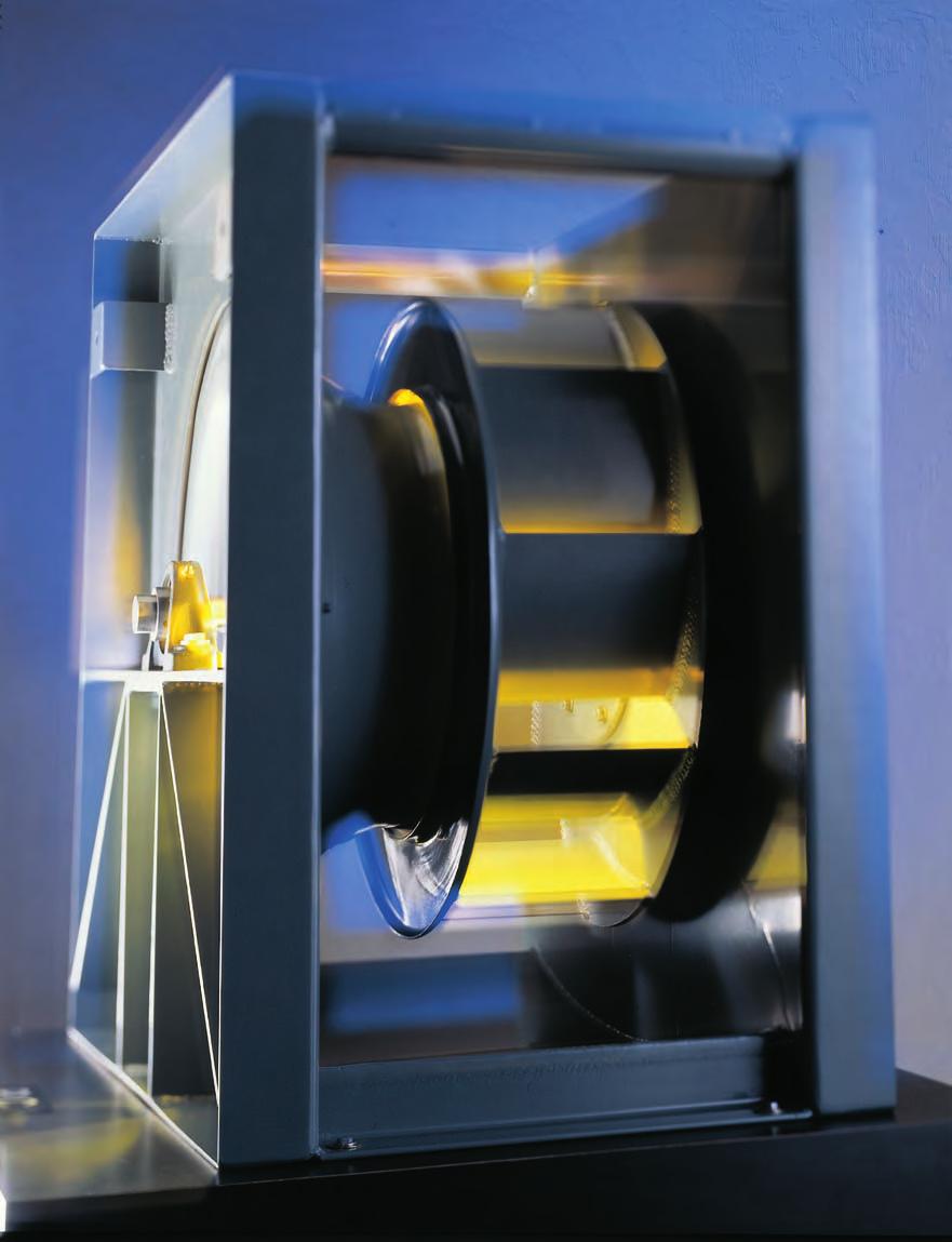
4 INTRODUCTION Loren Cook Company s Centrifugal Plenum Fan is an unhoused fan designed for operation in plenum installations such as air handling units. The fan pressurizes the plenum in which it operates so ductwork can be connected directly to the plenum. The fan s design saves space by eliminating the fan housing and ductwork transition to the fan discharge. The PLC is available in aluminum and steel construction with wheel sizes of 12 to 73 inches diameter and in Class I, II, and III. PLC is licensed to bear AMCA Certified Ratings Seal for Sound and Air Performance. Performance is licensed for both inlet and outlet sound. UL/cUL 705 listing is standard on all PLC models. The PLC has a true airfoil wheel optimized for maximum efficiency. All blades are continuously welded to the wheel shroud and backplate. Optimized housing for weight savings while maintaining structural integrity. Extended lube line standard on inlet side bearing to allow for lubrication from drive side. Top braces designed to provide lifting points to aid in installation. The PLC was designed using the latest Computational Fluid Dynamics (CFD) and Finite Element Analysis (FEA) software. This allowed our engineers to optimize the inlet, wheel and housing through design iterations. Once the design was optimized, physical prototypes verfied the performance and durability of the design. The result is the most efficient plenum fan in the industry. 2
 High Efficiency Airfoil Wheel High Performance Air Flow")
5 STANDARD CONSTRUCTION FEATURES PLC Arrangement 3S (Belt Drive) Optimized Housing High Efficiency Airfoil Wheel Adjustable Motor Plate Air-handling Quality Ball or Roller Bearings Reversible Motor Pedestal PLC Arrangement 4 (Direct Drive) High Efficiency Airfoil Wheel High Performance Air Flow Baffle 3
6 PLC Specifications and Dimension Data Centrifugal Plenum Fan Loren Cook Company certifies that the PLC shown herein is licensed to bear the AMCA Seal. The ratings shown are based on tests and procedures performed in accordance with AMCA Publication 211 and AMCA Publication 311 and comply with the requirements of the AMCA Certified Ratings Program. Type PLC is furnished standard with UL 705 listing (cul 705) when furnished with factory supplied motor. Description - Fan shall be a single width, single inlet backward inclined centrifugal airfoil, belt or direct driven plenum blower as specified. Certifications - Fan shall be manufactured at an ISO 9001 certified facility. Fan shall be listed by Underwriters Laboratories (UL 705) and UL listed for Canada (cul 705). Fan shall bear the AMCA Certified Ratings Seal for Sound and Air Performance. Performance shall be certified for both inlet and outlet sound. Construction - The fan shall be of bolted and welded construction utilizing corrosion resistant fasteners. The inlet panel shall be constructed from heavy gauge reinforced steel with an integral rectangular formed duct connection. High performance airflow baffle shall be standard to reduce under unit turbulence and improve efficiency. Integral lifting points shall be standard. Unit shall bear an engraved aluminum nameplate. Nameplate shall indicate design CFM, static pressure and maximum fan RPM. Unit shall be shipped in ISTA Certified Transit Tested Packaging. Coating - Steel fan components shall be Lorenized with an electrostatically applied, baked polyester powder coating. Each component shall be subject to a five stage environmentally friendly wash system, followed by a minimum 2 mil thick baked powder finish. Paint must exceed 1,000 hour salt spray under ASTM B117 test method. Wheel - Wheel shall be steel, non-overloading, centrifugal backward inclined, high efficiency, airfoil type. Blades on all sizes shall be continuously welded to the backplate and inlet shroud. All sizes shall be securely keyed to the fan shaft. Wheel shall overlap an aerodynamic aluminum inlet cone to provide maximum performance and efficiency. Wheel shall be balanced in accordance with AMCA Standard , Balance Quality and Vibration Levels for Fans. Motor - Motor shall be Nema design B with class B insulation rated for continuous duty and furnished at the specified voltage, phase and enclosure. Blower Shaft - Blower shaft shall be AISI C-1045 hot rolled and accurately turned, ground and polished. Shafting shall be sized for a critical speed of at least 125% of maximum RPM. Bearings - Bearings shall be designed and tested specifically for use in air handling applications. Construction shall be heavy duty regreasable ball or roller type in a cast iron pillow block housing selected for a minimum L50 life in excess of 200,000 hours at maximum cataloged operating speed. Belts and Drives - Belts shall be oil and heat resistant, non-static type. Drives shall be precision machined cast iron type, keyed and securely attached to the wheel and motor shafts. Drives shall be sized for 150% of the installed motor horsepower. The variable pitch motor drive must be factory set to the specified fan RPM. Product - Fan shall be model PLC as manufactured by Loren Cook Company of Springfield, Missouri. Size Size
7 Specifications and Dimension Data PLC PLC Dimension Data Size A B C D E F Class I Class II Class III Class I Class II Class III /4 17-1/4 8-5/8 8-5/8 7-15/ / / / /2 19-1/2 9-3/4 9-3/4 9-1/16 9-1/ /8 14-5/ /2 21-1/2 10-3/4 10-3/4 9-13/ / / / /4 23-3/4 11-7/8 11-7/ / / /4 16-3/ /4 25-3/4 12-7/8 12-7/ / / / /8 19-7/8 20-5/ / / / / /8 14-1/ / / / / /4 32-1/4 16-1/8 16-1/8 15-1/4 15-5/ / / / / /2 17-1/2 16-3/8 16-7/ / /2 24-1/2 25-9/ /4 38-3/4 19-3/8 19-3/8 18-1/4 18-5/ / / / /2 21-1/2 20-3/ / / /2 29-1/2 31-1/ / / / /4 22-1/4 32-3/ / / / /8 24-1/ / /4 23-3/4 34-9/ /8 36-5/ / /4 26-1/8 26-1/8 39-7/ / /2 31-7/8 29-1/4 28-1/2 28-3/8 28-3/ /2 30-5/8 30-1/2 30-1/2 47-1/ / / /8 34-1/2 33-5/8 33-1/2 33-1/2 50-7/8 54-3/8 54-3/ /8 37-1/2 36-5/8 36-1/2 36-1/2 56-1/4 59-1/4 59-1/ / / / / / / / / / / /4 69-3/4 All dimensions in inches. PLC Dimension Data Continued Size Class I G Class II Class III Class I H Class II Class III Class I J Class II Class III / / / / / / / / / / /16 9-7/16-2-1/16 2-1/16-3-1/16 3-1/ /8 10-5/8-2-1/16 2-1/16-3-1/16 3-1/ /4 11-3/4 10-3/4 3-1/16 3-1/16 3-1/16 4-1/16 4-1/16 4-9/ /8 12-7/8 11-7/8 3-1/16 3-1/16 3-1/16 4-1/16 4-1/16 4-9/ / / /16 3-1/16 3-1/16 3-1/16 4-1/16 4-1/16 4-9/ / / /16 3-1/16 3-1/16 3-1/16 4-1/16 4-1/16 4-9/ /8 15-7/8 15-3/8 3-9/16 3-9/16 3-1/16 4-5/16 4-5/16 4-9/ / / /16 3-9/16 3-9/16 3-9/ / /16 5-1/ /8 19-3/8 19-3/8 3-9/16 3-9/16 3-9/16 5-1/16 5-1/16 5-1/ /8 27-3/8 27-3/8 3-9/16 4-9/16 4-9/ / / / / / /16 3-9/16 4-9/16 4-9/ / / / /8 33-5/8 33-5/8 4-1/8 5-1/16 5-1/8 5-1/4 6-3/16 6-1/ /8 36-5/8 36-5/8 5-1/8 6-1/8 6-1/8 6-1/4 7-1/4 7-1/ /8 41-7/8 41-7/8 5-1/8 6-9/16 6-9/16 6-1/4 7-11/ / /2 45-1/2 45-1/2 5-1/8 6-5/8 6-5/8 6-1/4 7-3/4 7-3/ /8 49-7/8 49-7/8 6-1/8 7-1/8 7-1/8 7-1/4 8-1/4 8-1/ / / /16 7-1/8 8-1/8 8-1/8 8-1/4 9-1/4 9-1/ / /8 59-3/8 8-1/8 8-1/8 8-1/8 9-1/4 9-1/4 9-1/4 All dimensions in inches. PLC Dimension Data Continued Size K L M Shipping Weight in lbs.* Class I Class II Class III Class I Class II Class III Class I Class II Class III Class I Class II Class III / /16-5/8 5/8-1-3/16 1-7/ /2 18-7/8-5/8 5/8-1-3/16 1-7/ /2 19-7/8-5/8 5/8-1-3/16 1-7/ / /16-5/8 5/8-1-3/16 1-7/ / / /16 5/8 5/8 5/8 1-7/16 1-7/ / /8 25-1/ /16 5/8 5/8 5/8 1-7/16 1-7/ / / / /8 5/8 5/8 1-7/16 1-7/ / / / /8 5/8 5/8 5/8 1-7/ / / / / /16 5/8 5/8 5/8 1-7/ /16 2-3/ / / /4 5/8 5/8 5/8 1-7/ /16 2-7/ / / /16 5/8 5/8 5/8 1-11/16 2-3/16 2-7/ / / /16 15/16 15/16 15/ /16 2-3/16 2-7/ /8 41-5/8 42-1/2 15/16 15/16 15/ /16 2-3/ / / /4 47-3/8 15/16 15/16 15/16 2-7/16 2-3/ / /8 50-3/4 51-7/8 15/16 15/16 15/16 2-7/16 2-7/16 3-7/ / / /16 15/16 1-1/16 1-1/16 2-7/ /16 3-7/ / /8 1-1/16 1-1/16 1-1/16 2-7/ /16 3-7/ /4 66-5/8 68-1/8 1-1/16 1-1/16 1-1/ /16 3-7/ / / / /16 1-1/16 1-1/16 1-1/ /16 3-7/ / / /8 80-5/8 1-1/16 1-1/16 1-1/16 3-7/16 3-7/16 4-7/ All dimensions in inches. *Less motor, Arr. 3. 5
8 CONSTRUCTION INFORMATION Airfoil Steel and Aluminum Wheel Airfoil Steel Wheel PLC Airfoil Aluminum Wheel PLC PLC Size Class I Class II Class III Class I Class II Class III Wheel Wt. Wk 2 Wheel Wt. Wk 2 Wheel Wt. Wk 2 Wheel Wt. Wk 2 Wheel Wt. Wk 2 Wheel Wt. Wk Motor Selection Guidelines For proper motor selection, consideration must be given to starting torque requirements along with operating BHP. The Airfoil Steel and Aluminum Wheel and Flatblade Steel and Aluminum Wheel tables (above) lists the WK 2 factor for different wheel sizes and types.in some cases it may be necessary to provide a larger horsepower motor, even though it may not be indicated by operating BHP, in order to bring the fan to speed. The following formula can be applied to determine the required motor starting torque. WK 2 m = WK 2 f (FRPM / MRPM) 2 (1.1) WK 2 m = the moment of inertia required at the motor shaft, Lb. - ft2. WK 2 f = the moment of inertia of the fan, Lb. - ft2. FRPM = Fan RPM. MRPM = Motor RPM. Motor starting torque can vary greatly among motor manufacturers, the available WK 2 m of the motor should be obtained from the motor manufacturer. Standard Coatings Lorenized is an electrostatically applied, baked polyester powder coating. Each component shall be subject to a five stage environmentally friendly wash system, followed by a minimum 2 mil thick baked powder finish. Coating must exceed 1,000 hour salt spray under ASTM B117 test method. Optional Coatings Cook Epoxy Powder is an electrostatically applied, baked epoxy powder coating. Final coating thickness is mils. For outdoor applications an optional UV resistant topcoat is available to prevent cosmetic chalking of the coating. Cook Phenolic Epoxy Powder is an electrostatically applied, baked phenolic epoxy powder coating. Final coating thickness is 2 4 mils. For outdoor applications an optional UV resistant topcoat is required to prevent deterioration of the coating. Air Dry Phenolic (Heresite VR-504) is a conventional spray applied phenolic resin coating. Final coating thickness is 4 6 mils. For outdoor applications an optional UV resistant topcoat (Heresite UC-5500) is required to prevent deterioration of the coating. Refer to the corrosion resistance guide in the Compute-A-Fan software for a listing of the coatings above and their resistance to a variety of chemicals. Additional special coatings are available. 6


9 DRIVE ARRANGEMENTS Horizontal Arrangement 3 PLC Horizontal Arrangement 3 is available in sizes 120 to 730 and in Class I, II and III construction. This arrangement does not provide for motor mounting on the unit. The fan and motor should be mounted on a common isolation base in one of the four standard motor positions (W, X, Y, Z) as illustrated in the motor position chart shown below. Horizontal Arrangement 3 with Side Mounted Motor PLC Horizontal Arrangement 3 with side-mounted motor is available in sizes 120 to 730 and in Class I & II only. This arrangement can be used for applications where space limitations are critical. Due to uneven weight distribution, special care must be taken to ensure correct selection of isolators is made. Motor is located on right side as standard to provide clearance and access to motor wiring compartment. Left side motor arrangement is made easy by a universal motor base. Horizontal Arrangement 3 with Top Mounted Motor PLC Horizontal Arrangement 3 with top-mounted motor is available in sizes 270 to 730 and in Class I only. This arrangement can be used for applications where floor space limitations are critical. This arrangement also includes additional bracing for the adjustable motor mount as well as for a more centralized motor location. Vertical Arrangement 3 with Side Mounted Motor PLC Vertical Arrangement 3 is available in sizes 120 to 730 and in Class I and II construction only. This arrangement includes an adjustable motor mount and a structural angle flange around the inlet panel for mounting on isolators or a isolation base. Arrangement 4 Direct Drive PLC Arrangement 4 is available for applications requiring direct drive in Class I, II and III construction. This arrangement is desirable for applications where belt residue would contaminate the air stream. Wheel width modifications are available to achieve desired performance at direct drive motor speeds. See page 9 for performance ranges. Arrangement 1 PLC Arrangement 1 is available in sizes 120 to 730 in Class I, II and III construction. This arrangement is best suited for applications where floor space is not critical and a ducted inlet connection is desired. Since this arrangement does not have a bearing in the inlet air stream, the inlet connection is much cleaner. Arrangement 1 does not provide for motor mounting on the unit. The fan and motor should be mounted on a separate common isolation base in one of the four standard motor positions (W, X, Y, Z) as illustrated in the motor position chart shown below. Z Y X W Motor Position Chart The fan shaft drive end is normally opposite the inlet side. Where fan is to be driven from the inlet side, specify inlet side drives. Standard rotation is counterclockwise. If opposite rotation is required, specify clockwise rotation. When two fans are used in parallel in a common plenum, opposite rotation designs are recommended. Rotation is always determined from the drive side. 7
10 APPLICATION INFORMATION Duct Entrance Losses from Plenum Fan Cabinet In order to compensate for the losses associated with the air entering the ductwork, additional resistance must be added to the external static pressure requirements for the fan. The corrections required vary based on type of entrance and the location of the entrance relative to the fan. The attached chart can be used to define the loss coefficient required for standard air applications. On fans with mulitple discharges, choose the discharge with the highest loss coefficient to calculate the correction. Formula: Duct Entrance Pressure Loss = C d x [(CFM/Duct Area)/4005] 2 Duct Entrance Loss Coefficients Radial C d Axial Unducted Ducted Ducted w/bell Wall Proximity Factors In cases where walls are placed in close proximity to the plenum fan corrections are necessary. The corrections can be made using the following procedure: Step 1: Calculate the %WOV M factor from chart below. %WOV = CFM/(M x Fan RPM) Step 2: Determine Ci/Di wall proximity factor. Ci is the clearance between wheel tip and wall and Di is the wheel diameter, both in inches. Factor = Ci/Di Step 3: Use chart below to obtain correction factors for BHP and RPM and correct both using appropriate factor. Unhoused Wall Proximity Factors %WOV RPM/ BHP One Wall Two Wall Three Wall Ci/Di Ci/Di Ci/Di RPM BHP RPM BHP RPM BHP RPM BHP RPM BHP RPM BHP RPM BHP RPM BHP RPM BHP RPM BHP RPM BHP RPM BHP Di is the wheel diameter in inches. Ci is the clearance between wheel tip and wall in inches. For multiple wall conditions, there may be several values for Ci. In this case calculate for all Ci values and use the highest resulting RPM and BHP factors. AMCA Certified Ratings Seal does not apply when these factors are used. PLC M Factors Size M


11 PLC Arrangement 4 DIRECT DRIVE PLC is available in direct drive, Arrangement 4 configuration, for sizes 150 to 730. The charts below represent the recommended selections for each available motor speed. Each fan size is represented by a colored band that indicates the performance range for the given motor RPM. The performance ranges for each size are created through the use of partial width wheels. In order to vary the fan performance with a fixed RPM, the physical width of the wheel is adjusted and therefore change the amount of air the blower is capable of moving. The PLC direct drives are available from 50 to 100% air performance based on the full width performance at each motor RPM. For exact performance, consult the Compute-A-Fan selection software. 690 RPM 870 RPM Static Pressure (In W.G.) Static Pressure (In W.G.) Flow (CFM) Flow (CFM) 1170 RPM 1770 RPM Static Pressure (In W.G.) Static Pressure (In W.G.) Flow (CFM) Flow (CFM) 9

12 ACCESSORIES PLC (Arrangement 3 shown) Safety Enclosure* * Guards shown in optional safety yellow. Inlet Safety Screen Belt Guard* Flanged Inlet External Inlet Vane Damper Isolation Base Inlet Companion Flange Isolator Inlet Safety Screen A removable safety screen is available to protect personnel and prevent debris from entering non-ducted inlets. Catalog performance is based on fans without inlet safety screens. Isolation Base Isolation bases are available for PLC Arrangement 3 fans. The isolation base is constructed of heavy duty structural channel. Specify one of the four standard motor positions as illustrated in the motor position chart (page 7), optional height saving brackets are available for use with spring isolators. Inlet Companion Flange A companion flange is available for use with the optional flange inlet. A flange inlet must be ordered separately and is required when ordering a companion flange. Belt Guard A belt guard is available to enclose the belts and drives. Available in both solid construction or optional expanded metal. Available in optional safety yellow. Safety Enclosure The safety enclosure is an expanded motor screen with a heavy steel frame that completely encloses the fan wheel. Available in optional safety yellow. Catalog performance is based on fans without safety enclosures. 10
13 ACCESSORIES Flanged Inlet Flanged inlet connections are available for applications requiring flanged inlet duct connections. Flanged inlets are available on all arrangements. Flanged inlet connection is required when using external inlet vane dampers on Arrangement 3 fans. FLANGED INLET A ID B C BLOWER HOUSING INLET CONE PLC Size A B C /8 1-1/2 5-3/ /8 1-1/2 5-3/ /8 1-1/2 5-3/ / / / / / / / / / / / / / / / / / / / / / / / / / / / / / / /4 All dimensions in inches. Inlet Collar Inlet collars are available to provide for a round slip fit inlet connection. Inlet collars are standard on Arrangements 1 and 4 and optional (though not recommended) on Arrangement 3. B A ID PLC Size A B /8 3-3/ /8 3-3/ /8 3-3/ /8 3-3/ /8 3-3/ / /4 4-5/ /4 4-5/ /4 4-5/ /4 4-3/ /4 4-1/ /4 4-1/ /4 4-1/ / /4 3-1/ /4 3-3/ / / / /8 All dimensions in inches. Inlet Vane Damper Inlet vane dampers are available in nested or external type. Inlet vane dampers are used to provide precise air volume control while maintaining maximum efficiency and stable operation at part load conditions. Nested type Inlet Vane Dampers are typically used in non-ducted applications, while external Inlet Vane Dampers are use in ducted applications. Nested type is available on sizes 245 to 730. External type is available on sizes 120 to 730. External inlet vane dampers used on Arrangement 3 fans require optional flanged inlet connection and should only be used when a direct inlet duct connection is required. Cataloged performance is based on fans without inlet vane dampers. Nested External C B OD A ID PLC Size A B C Approx. Ship Wt. Lbs. Alum. Ext /8 15-7/ /8 17-3/ /8 18-7/ /8 20-3/ /8 21-7/ /4 24-3/ /4 26-1/ /4 28-1/ /4 31-1/ /4 34-1/ /4 37-1/ /4 40-3/ /2 44-1/ /4 48-3/ /4 54-1/ /4 59-1/ /4 65-1/ /4 71-1/ /4 78-1/ All dimensions in inches. 11
14 STATIC PRESSURE (In W.G.) PLC Data 120 PLC Wheel Diameter - 12 Wheel Type - Airfoil Tip Speed (FPM) = 3.14 x RPM Max. BHP =.057 x (RPM/1000) 3 Inlet Area -.92 Sq. Ft. Outlet Area Sq. Ft. Outlet Velocity (FPM) = CFM/1.14 Class I Max. RPM Class II Max. RPM /4 120 PLC RPM RPM 3300 RPM 3000 RPM 2600 RPM 2200 RPM 1569 RPM RPM Max Class RPM Max Class 1.75 HP 1.5 HP 1 HP.5 HP 2 HP 3 HP 5 HP 7.5 HP FLOW (CFM) 17-1/4 13-1/16 Max. 135 PLC Wheel Diameter Wheel Type - Airfoil Tip Speed (FPM) = 3.53 x RPM Max. BHP =.103 x (RPM/1000) 3 Inlet Area Sq. Ft. Outlet Area Sq. Ft. Outlet Velocity (FPM) = CFM/1.44 Class I Max. RPM Class II Max. RPM /2 135 PLC STATIC PRESSURE (In W.G.) RPM Max Class RPM 3642 RPM Max Class RPM 2900 RPM 2600 RPM 2300 RPM 2000 RPM 1339 RPM.5 HP.75 HP 1.5 HP 1 HP 2 HP 3 HP 5 HP 7.5 HP FLOW (CFM) 19-1/2 14-5/8 Max. 150 PLC Wheel Diameter - 15 Wheel Type - Airfoil Tip Speed (FPM) = 3.93 x RPM Max. BHP =.174 x (RPM/1000) 3 Inlet Area Sq. Ft. Outlet Area Sq. Ft. Outlet Velocity (FPM) = CFM/1.77 Class I Max. RPM Class II Max. RPM /2 150 PLC STATIC PRESSURE (In W.G.) RPM Max Class RPM 3232 RPM Max Class RPM 2600 RPM 2300 RPM 2000 RPM 1800 RPM 1196 RPM.75 HP 1 HP.5 HP 1.5 HP 5 HP 3 HP 7.5 HP 2 HP 10 HP FLOW (CFM) 21-1/2 15-9/16 Max. Performance certified is for Installation Type A: Free Inlet, Free Outlet. Power rating (BHP) does not include transmission losses. Performance ratings do not include the effects of appurtenances (accessories). 12
15 13 Data PLC PLC CFM OV SP SP SP SP SP SP SP SP 1 SP RPM BHP RPM BHP RPM BHP RPM BHP RPM BHP RPM BHP RPM BHP RPM BHP RPM BHP PLC CFM OV SP SP SP SP SP SP SP SP 1 SP RPM BHP RPM BHP RPM BHP RPM BHP RPM BHP RPM BHP RPM BHP RPM BHP RPM BHP PLC CFM OV SP SP SP SP SP SP SP SP 1 SP RPM BHP RPM BHP RPM BHP RPM BHP RPM BHP RPM BHP RPM BHP RPM BHP RPM BHP Performance certified is for Installation Type A: Free Inlet, Free Outlet. Power rating (BHP) does not include transmission losses. Performance ratings do not include the effects of appurtenances (accessories).
16 STATIC PRESSURE (In W.G.) STATIC PRESSURE (In W.G.) PLC Data 165 PLC Wheel Diameter Wheel Type - Airfoil Tip Speed (FPM) = 4.32 x RPM Max. BHP =.280 x (RPM/1000) 3 Inlet Area Sq. Ft. Outlet Area Sq. Ft. Outlet Velocity (FPM) = CFM/2.15 Class I Max. RPM Class II Max. RPM /4 165 PLC STATIC PRESSURE (In W.G.) RPM Max Class RPM 2800 RPM 2600 RPM 2300 RPM 2100 RPM 1800 RPM 1600 RPM.75 HP 1078 RPM.5 HP Max Class 1 2 HP 1.5 HP 1 HP 5 HP 7.5 HP 3 HP 10 HP FLOW (CFM) 23-3/4 16-3/4 Max. 180 PLC Wheel Diameter - 18 Wheel Type - Airfoil Tip Speed (FPM) = 4.71 x RPM Max. BHP =.382 x (RPM/1000) 3 Inlet Area Sq. Ft. Outlet Area Sq. Ft. Outlet Velocity (FPM) = CFM/2.56 Class I Max. RPM Class II Max. RPM Class III Max. RPM /4 180 PLC RPM 994 RPM 1 HP 2 HP.75 HP 1.5 HP 3800 RPM 2980 RPM Max Class RPM 2532 RPM Max Class RPM 1700 RPM 5 HP 3 HP 7.5 HP 10 HP 4101 RPM Max Class 3 15 HP FLOW (CFM) 20 HP 30 HP 25 HP 25-3/4 20-5/16 Max. 195 PLC Wheel Diameter Wheel Type - Airfoil Tip Speed (FPM) = 5.11 x RPM Max. BHP =.570 x (RPM/1000) 3 Inlet Area Sq. Ft. Outlet Area - Sq. Ft. Outlet Velocity (FPM) = CFM/ Class I Max. RPM Class II Max. RPM Class III Max. RPM PLC RPM RPM 2722 RPM Max Class RPM 2291 RPM Max Class RPM 1500 RPM 0.75 HP 918 RPM 1.5 HP 1 HP 5 HP 2 HP 7.5 HP 3 HP 3682 RPM Max Class 3 15 HP 10 HP 20 HP FLOW (CFM) 25 HP 30 HP /16 Max. Performance certified is for Installation Type A: Free Inlet, Free Outlet. Power rating (BHP) does not include transmission losses. Performance ratings do not include the effects of appurtenances (accessories). 14
17 Data PLC PLC CFM OV SP SP SP SP SP SP SP SP 1 SP RPM BHP RPM BHP RPM BHP RPM BHP RPM BHP RPM BHP RPM BHP RPM BHP RPM BHP PLC CFM OV SP SP SP SP SP SP SP SP 1 SP RPM BHP RPM BHP RPM BHP RPM BHP RPM BHP RPM BHP RPM BHP RPM BHP RPM BHP PLC CFM OV SP SP SP SP SP SP SP SP 1 SP RPM BHP RPM BHP RPM BHP RPM BHP RPM BHP RPM BHP RPM BHP RPM BHP RPM BHP Performance certified is for Installation Type A: Free Inlet, Free Outlet. Power rating (BHP) does not include transmission losses. Performance ratings do not include the effects of appurtenances (accessories). 15
18 STATIC PRESSURE (In W.G.) STATIC PRESSURE (In W.G.) PLC Data 210 PLC Wheel Diameter - 21 Wheel Type - Airfoil Tip Speed (FPM) = 5.50 x RPM Max. BHP =.83 x (RPM/1000) 3 Inlet Area Sq. Ft. Outlet Area Sq. Ft. Outlet Velocity (FPM) = CFM/3.48 Class I Max. RPM Class II Max. RPM Class III Max. RPM PLC STATIC PRESSURE (In W.G.) RPM RPM 2504 RPM Max Class RPM 1700 RPM 1400 RPM 853 RPM 1 HP RPM Max Class HP 5 HP 3 HP 2 HP 3333 RPM Max Class HP 15 HP 10 HP 20 HP 25 HP FLOW (CFM) 30 HP 40 HP /8 Max. 225 PLC Wheel Diameter Wheel Type - Airfoil Tip Speed (FPM) = 5.89 x RPM Max. BHP = 1.17 x (RPM/1000) 3 Inlet Area Sq. Ft. Outlet Area Sq. Ft. Outlet Velocity (FPM) = CFM/3.99 Class I Max. RPM Class II Max. RPM Class III Max. RPM /4 225 PLC RPM RPM RPM Max Class RPM 1939 RPM Max Class RPM 1300 RPM 795 RPM HP 1 HP 3 HP 5 HP 2 HP 3062 RPM Max Class 3 10 HP 7.5 HP 15 HP 20 HP 25 HP 30 HP 40 HP FLOW (CFM) 32-1/4 24-1/8 Max. 245 PLC Wheel Diameter Wheel Type - Airfoil Tip Speed (FPM) = 6.41 x RPM Max. BHP = 1.99 x (RPM/1000) 3 Inlet Area Sq. Ft. Outlet Area Sq. Ft. Outlet Velocity (FPM) = CFM/4.73 Class I Max. RPM Class II Max. RPM Class III Max. RPM PLC RPM 2300 RPM 2112 RPM Max Class RPM Max Class RPM 1400 RPM 1200 RPM 1.5 HP 716 RPM 2 HP 5 HP 3 HP 10 HP 2732 RPM Max Class 3 15 HP 7.5 HP 20 HP 25 HP 40 HP 30 HP 50 HP FLOW (CFM) /16 Max. Performance certified is for Installation Type A: Free Inlet, Free Outlet. Power rating (BHP) does not include transmission losses. Performance ratings do not include the effects of appurtenances (accessories). 16
19 Data PLC PLC CFM OV SP SP SP SP SP SP SP SP 1 SP RPM BHP RPM BHP RPM BHP RPM BHP RPM BHP RPM BHP RPM BHP RPM BHP RPM BHP PLC CFM OV SP SP SP SP SP SP SP SP 1 SP RPM BHP RPM BHP RPM BHP RPM BHP RPM BHP RPM BHP RPM BHP RPM BHP RPM BHP PLC CFM OV SP SP SP SP SP SP SP SP 1 SP RPM BHP RPM BHP RPM BHP RPM BHP RPM BHP RPM BHP RPM BHP RPM BHP RPM BHP Performance certified is for Installation Type A: Free Inlet, Free Outlet. Power rating (BHP) does not include transmission losses. Performance ratings do not include the effects of appurtenances (accessories). 17
20 STATIC PRESSURE (In W.G.) STATIC PRESSURE (In W.G.) PLC Data 270 PLC Wheel Diameter - 27 Wheel Type - Airfoil Tip Speed (FPM) = 7.07 x RPM Max. BHP = 3.24 x (RPM/1000) 3 Inlet Area Sq. Ft. Outlet Area Sq. Ft. Outlet Velocity (FPM) = CFM/5.75 Class I Max. RPM Class II Max. RPM Class III Max. RPM /4 STATIC PRESSURE (In W.G.) 270 PLC RPM Max Class RPM RPM RPM Max Class RPM Max Class RPM 1250 RPM 1050 RPM HP 649 RPM 5 HP 2 HP 7.5 HP 3 HP 15 HP 10 HP 20 HP 25 HP 50 HP 40 HP 30 HP FLOW (CFM) 38-3/4 29 Max. 300 PLC Wheel Diameter - 30 Wheel Type - Airfoil Tip Speed (FPM) = 7.85 x RPM Max. BHP = 5.49 x (RPM/1000) 3 Inlet Area Sq. Ft. Outlet Area Sq. Ft. Outlet Velocity (FPM) = CFM/7.10 Class I Max. RPM Class II Max. RPM Class III Max. RPM PLC RPM RPM RPM 1150 RPM 950 RPM 1685 RPM Max Class RPM Max Class 1 3 HP 5 HP 7.5 HP 2233 RPM Max Class 3 15 HP 10 HP 30 HP 20 HP 40 HP 25 HP 50 HP 60 HP 585 RPM2 HP FLOW (CFM) 75 HP /16 Max. 330 PLC Wheel Diameter - 33 Wheel Type - Airfoil Tip Speed (FPM) = 8.64 x RPM Max. BHP = 8.84 x (RPM/1000) 3 Inlet Area Sq. Ft. Outlet Area Sq. Ft. Outlet Velocity (FPM) = CFM/8.59 Class I Max. RPM Class II Max. RPM Class III Max. RPM /2 330 PLC RPM Max Class RPM RPM RPM 850 RPM 532 RPM2 HP RPM Max Class RPM Max Class RPM 3 HP 5 HP 10 HP 7.5 HP 25 HP 40 HP 20 HP 15 HP 50 HP 30 HP 60 HP 75 HP FLOW (CFM) /16 Max. Performance certified is for Installation Type A: Free Inlet, Free Outlet. Power rating (BHP) does not include transmission losses. Performance ratings do not include the effects of appurtenances (accessories). 18
21 Data PLC PLC CFM OV SP SP SP SP SP SP SP SP 1 SP RPM BHP RPM BHP RPM BHP RPM BHP RPM BHP RPM BHP RPM BHP RPM BHP RPM BHP PLC CFM OV SP SP SP SP SP SP SP SP 1 SP RPM BHP RPM BHP RPM BHP RPM BHP RPM BHP RPM BHP RPM BHP RPM BHP RPM BHP PLC CFM OV SP SP SP SP SP SP SP SP 1 SP RPM BHP RPM BHP RPM BHP RPM BHP RPM BHP RPM BHP RPM BHP RPM BHP RPM BHP Performance certified is for Installation Type A: Free Inlet, Free Outlet. Power rating (BHP) does not include transmission losses. Performance ratings do not include the effects of appurtenances (accessories). 19
22 PLC Data 365 PLC Wheel Diameter Wheel Type - Airfoil Tip Speed (FPM) = 9.56 x RPM Max. BHP = 14.0 x (RPM/1000) 3 Inlet Area Sq. Ft. Outlet Area Sq. Ft. Outlet Velocity (FPM) = CFM/10.51 Class I Max. RPM Class II Max. RPM Class III Max. RPM /2 STATIC PRESSURE (In W.G.) 365 PLC RPM Max Class RPM RPM RPM Max Class RPM 900 RPM 750 RPM 480 RPM3 HP RPM Max Class 1 10 HP 5 HP 20 HP 40 HP 50 HP 30 HP 100 HP 75 HP 60 HP FLOW (CFM) /8 Max. 402 PLC Wheel Diameter Wheel Type - Airfoil Tip Speed (FPM) = x RPM Max. BHP = 22.8 x (RPM/1000) 3 Inlet Area Sq. Ft. Outlet Area Sq. Ft. Outlet Velocity (FPM) = CFM/12.78 Class I Max. RPM Class II Max. RPM Class III Max. RPM STATIC PRESSURE (In W.G.) 402 PLC RPM Max Class RPM 1350 RPM RPM Max Class RPM 825 RPM 700 RPM 435 RPM 3 HP RPM Max Class 1 10 HP 5 HP 40 HP 20 HP 30 HP 50 HP 60 HP 75 HP 100 HP FLOW (CFM) Max. 445 PLC Wheel Diameter Wheel Type - Airfoil Tip Speed (FPM) = x RPM Max. BHP = 37.6 x (RPM/1000) 3 Inlet Area Sq. Ft. Outlet Area Sq. Ft. Outlet Velocity (FPM) = CFM/15.62 Class I Max. RPM Class II Max. RPM Class III Max. RPM PLC STATIC PRESSURE (In W.G.) RPM Max Class RPM RPM RPM 750 RPM 625 RPM 1149 RPM Max Class RPM Max Class RPM 10 HP 5 HP 20 HP 60 HP 30 HP 75 HP 100 HP 50 HP 125 HP FLOW (CFM) 58-1/2 45 Max. Performance certified is for Installation Type A: Free Inlet, Free Outlet. Power rating (BHP) does not include transmission losses. Performance ratings do not include the effects of appurtenances (accessories). 20
23 Data PLC PLC CFM OV SP SP SP SP SP SP SP SP 1 SP RPM BHP RPM BHP RPM BHP RPM BHP RPM BHP RPM BHP RPM BHP RPM BHP RPM BHP PLC CFM OV SP SP SP SP SP SP SP SP 1 SP RPM BHP RPM BHP RPM BHP RPM BHP RPM BHP RPM BHP RPM BHP RPM BHP RPM BHP PLC CFM OV SP SP SP SP SP SP SP SP 1 SP RPM BHP RPM BHP RPM BHP RPM BHP RPM BHP RPM BHP RPM BHP RPM BHP RPM BHP Performance certified is for Installation Type A: Free Inlet, Free Outlet. Power rating (BHP) does not include transmission losses. Performance ratings do not include the effects of appurtenances (accessories). 21
24 STATIC PRESSURE (In W.G.) PLC Data 490 PLC Wheel Diameter - 49 Wheel Type - Airfoil Tip Speed (FPM) = x RPM Max. BHP = 60.9 x (RPM/1000) 3 Inlet Area Sq. Ft. Outlet Area Sq. Ft. Outlet Velocity (FPM) = CFM/18.94 Class I Max. RPM Class II Max. RPM Class III Max. RPM STATIC PRESSURE (In W.G.) 490 PLC RPM Max Class RPM 1100 RPM 1031 RPM Max Class RPM Max Class RPM 675 RPM 575 RPM 357 RPM 5 HP 30 HP 20 HP 10 HP 50 HP 75 HP 100 HP 125 HP 150 HP FLOW (CFM) /16 Max. 540 PLC Wheel Diameter - 54 Wheel Type - Airfoil Tip Speed (FPM) = x RPM Max. BHP = 98.9 x (RPM/1000) 3 Inlet Area Sq. Ft. Outlet Area - 2 Sq. Ft. Outlet Velocity (FPM) = CFM/2 Class I Max. RPM Class II Max. RPM Class III Max. RPM PLC STATIC PRESSURE (In W.G.) RPM Max Class RPM 1000 RPM RPM Max Class RPM 625 RPM 525 RPM 929 RPM Max Class 2 10 HP 30 HP 20 HP 75 HP 50 HP 100 HP 125 HP 150 HP 200 HP 324 RPM5 HP FLOW (CFM) /8 Max. 600 PLC Wheel Diameter - 60 Wheel Type - Airfoil Tip Speed (FPM) = x RPM Max. BHP = x (RPM/1000) 3 Inlet Area Sq. Ft. Outlet Area Sq. Ft. Outlet Velocity (FPM) = CFM/28.39 Class I Max. RPM Class II Max. RPM Class III Max. RPM PLC RPM Max Class RPM RPM RPM Max Class RPM 560 RPM 470 RPM 292 RPM RPM Max Class HP 15 HP 25 HP 75 HP 125 HP 50 HP 150 HP 200 HP 100 HP 250 HP FLOW (CFM) /4 Max. Performance certified is for Installation Type A: Free Inlet, Free Outlet. Power rating (BHP) does not include transmission losses. Performance ratings do not include the effects of appurtenances (accessories). 22
25 Data PLC PLC CFM OV SP SP SP SP SP SP SP SP 1 SP RPM BHP RPM BHP RPM BHP RPM BHP RPM BHP RPM BHP RPM BHP RPM BHP RPM BHP PLC CFM OV SP SP SP SP SP SP SP SP 1 SP RPM BHP RPM BHP RPM BHP RPM BHP RPM BHP RPM BHP RPM BHP RPM BHP RPM BHP PLC CFM OV SP SP SP SP SP SP SP SP 1 SP RPM BHP RPM BHP RPM BHP RPM BHP RPM BHP RPM BHP RPM BHP RPM BHP RPM BHP Performance certified is for Installation Type A: Free Inlet, Free Outlet. Power rating (BHP) does not include transmission losses. Performance ratings do not include the effects of appurtenances (accessories). 23
26 STATIC PRESSURE (In W.G.) PLC Data 660 PLC Wheel Diameter - 66 Wheel Type - Airfoil Tip Speed (FPM) = x RPM Max. BHP = x (RPM/1000) 3 Inlet Area Sq. Ft. Outlet Area Sq. Ft. Outlet Velocity (FPM) = CFM/34.35 Class I Max. RPM Class II Max. RPM Class III Max. RPM PLC RPM Max Class RPM 800 RPM RPM Max Class RPM Max Class RPM 500 RPM 420 RPM 265 RPM 10 HP 20 HP 50 HP 30 HP 75 HP 125 HP 250 HP 150 HP 100 HP 200 HP FLOW (CFM) /16 Max. 730 PLC Wheel Diameter - 73 Wheel Type - Airfoil Tip Speed (FPM) = x RPM Max. BHP = x (RPM/1000) 3 Inlet Area Sq. Ft. Outlet Area Sq. Ft. Outlet Velocity (FPM) = CFM/42.03 Class I Max. RPM Class II Max. RPM Class III Max. RPM STATIC PRESSURE (In W.G.) 730 PLC RPM Max Class RPM RPM 658 RPM Max Class RPM 440 RPM 370 RPM 240 RPM 10 HP RPM Max Class 1 30 HP 20 HP 50 HP 150 HP 75 HP 200 HP 250 HP 125 HP 300 HP FLOW (CFM) /4 Max. Performance certified is for Installation Type A: Free Inlet, Free Outlet. Power rating (BHP) does not include transmission losses. Performance ratings do not include the effects of appurtenances (accessories). 24
27 Data PLC PLC CFM OV SP SP SP SP SP SP SP SP 1 SP RPM BHP RPM BHP RPM BHP RPM BHP RPM BHP RPM BHP RPM BHP RPM BHP RPM BHP PLC CFM OV SP SP SP SP SP SP SP SP 1 SP RPM BHP RPM BHP RPM BHP RPM BHP RPM BHP RPM BHP RPM BHP RPM BHP RPM BHP Performance certified is for Installation Type A: Free Inlet, Free Outlet. Power rating (BHP) does not include transmission losses. Performance ratings do not include the effects of appurtenances (accessories). 25
28 PLC Sound Data 120 PLC RPM SP Sound Power re Watts Condition Octave Bands L w A Inlet Outlet Inlet Outlet Inlet Outlet Inlet Outlet Inlet Outlet Inlet Outlet Inlet Outlet Inlet Outlet Inlet Outlet Inlet Outlet Inlet Outlet Inlet Outlet Inlet Outlet Inlet Outlet Inlet Outlet Inlet Outlet Inlet Outlet Inlet Outlet Inlet Outlet Inlet Outlet Inlet Outlet Inlet Outlet Inlet Outlet Inlet Outlet Inlet Outlet PLC RPM SP Sound Power re Watts Condition Octave Bands L w A Inlet Outlet Inlet Outlet Inlet Outlet Inlet Outlet Inlet Outlet Inlet Outlet Inlet Outlet Inlet Outlet Inlet Outlet Inlet Outlet Inlet Outlet Inlet Outlet Inlet Outlet Inlet Outlet Inlet Outlet Inlet Outlet Inlet Outlet Inlet Outlet Inlet Outlet Inlet Outlet Inlet Outlet Inlet Outlet Inlet Outlet Inlet Outlet The sound power level ratings shown are in decibels referred to watts calculated per AMCA Standard 301. The A-weighted sound ratings shown has been calculated per AMCA Standard 301. Values shown are for inlet L Wi, L Wi A and outlet L wo, L wo A sound power levels for Installation Type A: free inlet, free outlet. Ratings do not include effects of duct end corrrection
29 150 PLC RPM SP Sound Power re Watts Condition Octave Bands L w A Inlet Outlet Inlet Outlet Inlet Outlet Inlet Outlet Inlet Outlet Inlet Outlet Inlet Outlet Inlet Outlet Inlet Outlet Inlet Outlet Inlet Outlet Inlet Outlet Inlet Outlet Inlet Outlet Inlet Outlet Inlet Outlet Inlet Outlet Inlet Outlet Inlet Outlet Inlet Outlet Inlet Outlet Inlet Outlet Inlet Outlet PLC RPM SP Sound Data PLC Sound Power re Watts Condition Octave Bands L w A Inlet Outlet Inlet Outlet Inlet Outlet Inlet Outlet Inlet Outlet Inlet Outlet Inlet Outlet Inlet Outlet Inlet Outlet Inlet Outlet Inlet Outlet Inlet Outlet Inlet Outlet Inlet Outlet Inlet Outlet Inlet Outlet Inlet Outlet Inlet Outlet Inlet Outlet Inlet Outlet Inlet Outlet Inlet Outlet Inlet Outlet Inlet Outlet Inlet Outlet The sound power level ratings shown are in decibels referred to watts calculated per AMCA Standard 301. The A-weighted sound ratings shown has been calculated per AMCA Standard 301. Values shown are for inlet L Wi, L Wi A and outlet L wo, L wo A sound power levels for Installation Type A: free inlet, free outlet. Ratings do not include effects of duct end corrrection
30 PLC Sound Data 180 PLC Sound Power re Watts RPM SP Condition Octave Bands L w A Inlet Outlet Inlet Outlet Inlet Outlet Inlet Outlet Inlet Outlet Inlet Outlet Inlet Outlet Inlet Outlet Inlet Outlet Inlet Outlet Inlet Outlet Inlet Outlet Inlet Outlet Inlet Outlet Inlet Outlet Inlet Outlet Inlet Outlet Inlet Outlet Inlet Outlet Inlet Outlet Inlet Outlet Inlet Outlet Inlet Outlet Inlet Outlet Inlet Outlet PLC Sound Power re Watts RPM SP Condition Octave Bands L w A Inlet Outlet Inlet Outlet Inlet Outlet Inlet Outlet Inlet Outlet Inlet Outlet Inlet Outlet Inlet Outlet Inlet Outlet Inlet Outlet Inlet Outlet Inlet Outlet Inlet Outlet Inlet Outlet Inlet Outlet Inlet Outlet Inlet Outlet Inlet Outlet Inlet Outlet Inlet Outlet Inlet Outlet Inlet Outlet Inlet Outlet Inlet Outlet Inlet Outlet The sound power level ratings shown are in decibels referred to watts calculated per AMCA Standard 301. The A-weighted sound ratings shown has been calculated per AMCA Standard 301. Values shown are for inlet L Wi, L Wi A and outlet L wo, L wo A sound power levels for Installation Type A: free inlet, free outlet. Ratings do not include effects of duct end corrrection. 28
31 210 PLC Sound Power re Watts RPM SP Condition Octave Bands L w A Inlet Outlet Inlet Outlet Inlet Outlet Inlet Outlet Inlet Outlet Inlet Outlet Inlet Outlet Inlet Outlet Inlet Outlet Inlet Outlet Inlet Outlet Inlet Outlet Inlet Outlet Inlet Outlet Inlet Outlet Inlet Outlet Inlet Outlet Inlet Outlet Inlet Outlet Inlet Outlet Inlet Outlet Inlet Outlet Inlet Outlet Inlet Outlet Inlet Outlet PLC Sound Data PLC Sound Power re Watts RPM SP Condition Octave Bands L w A Inlet Outlet Inlet Outlet Inlet Outlet Inlet Outlet Inlet Outlet Inlet Outlet Inlet Outlet Inlet Outlet Inlet Outlet Inlet Outlet Inlet Outlet Inlet Outlet Inlet Outlet Inlet Outlet Inlet Outlet Inlet Outlet Inlet Outlet Inlet Outlet Inlet Outlet Inlet Outlet Inlet Outlet Inlet Outlet Inlet Outlet Inlet Outlet Inlet Outlet The sound power level ratings shown are in decibels referred to watts calculated per AMCA Standard 301. The A-weighted sound ratings shown has been calculated per AMCA Standard 301. Values shown are for inlet L Wi, L Wi A and outlet L wo, L wo A sound power levels for Installation Type A: free inlet, free outlet. Ratings do not include effects of duct end corrrection. 29
32 PLC Sound Data 245 PLC Sound Power re Watts RPM SP Condition Octave Bands L w A Inlet Outlet Inlet Outlet Inlet Outlet Inlet Outlet Inlet Outlet Inlet Outlet Inlet Outlet Inlet Outlet Inlet Outlet Inlet Outlet Inlet Outlet Inlet Outlet Inlet Outlet Inlet Outlet Inlet Outlet Inlet Outlet Inlet Outlet Inlet Outlet Inlet Outlet Inlet Outlet Inlet Outlet Inlet Outlet Inlet Outlet Inlet Outlet Inlet Outlet PLC Sound Power re Watts RPM SP Condition Octave Bands L w A Inlet Outlet Inlet Outlet Inlet Outlet Inlet Outlet Inlet Outlet Inlet Outlet Inlet Outlet Inlet Outlet Inlet Outlet Inlet Outlet Inlet Outlet Inlet Outlet Inlet Outlet Inlet Outlet Inlet Outlet Inlet Outlet Inlet Outlet Inlet Outlet Inlet Outlet Inlet Outlet Inlet Outlet Inlet Outlet Inlet Outlet Inlet Outlet Inlet Outlet The sound power level ratings shown are in decibels referred to watts calculated per AMCA Standard 301. The A-weighted sound ratings shown has been calculated per AMCA Standard 301. Values shown are for inlet L Wi, L Wi A and outlet L wo, L wo A sound power levels for Installation Type A: free inlet, free outlet. Ratings do not include effects of duct end corrrection. 30
33 300 PLC Sound Power re Watts RPM SP Condition Octave Bands L w A Inlet Outlet Inlet Outlet Inlet Outlet Inlet Outlet Inlet Outlet Inlet Outlet Inlet Outlet Inlet Outlet Inlet Outlet Inlet Outlet Inlet Outlet Inlet Outlet Inlet Outlet Inlet Outlet Inlet Outlet Inlet Outlet Inlet Outlet Inlet Outlet Inlet Outlet Inlet Outlet Inlet Outlet Inlet Outlet Inlet Outlet Inlet Outlet Inlet Outlet PLC Sound Data PLC Sound Power re Watts RPM SP Condition Octave Bands L w A Inlet Outlet Inlet Outlet Inlet Outlet Inlet Outlet Inlet Outlet Inlet Outlet Inlet Outlet Inlet Outlet Inlet Outlet Inlet Outlet Inlet Outlet Inlet Outlet Inlet Outlet Inlet Outlet Inlet Outlet Inlet Outlet Inlet Outlet Inlet Outlet Inlet Outlet Inlet Outlet Inlet Outlet Inlet Outlet Inlet Outlet Inlet Outlet Inlet Outlet The sound power level ratings shown are in decibels referred to watts calculated per AMCA Standard 301. The A-weighted sound ratings shown has been calculated per AMCA Standard 301. Values shown are for inlet L Wi, L Wi A and outlet L wo, L wo A sound power levels for Installation Type A: free inlet, free outlet. Ratings do not include effects of duct end corrrection. 31
34 PLC Sound Data 365 PLC Sound Power re Watts RPM SP Condition Octave Bands L w A Inlet Outlet Inlet Outlet Inlet Outlet Inlet Outlet Inlet Outlet Inlet Outlet Inlet Outlet Inlet Outlet Inlet Outlet Inlet Outlet Inlet Outlet Inlet Outlet Inlet Outlet Inlet Outlet Inlet Outlet Inlet Outlet Inlet Outlet Inlet Outlet Inlet Outlet Inlet Outlet Inlet Outlet Inlet Outlet Inlet Outlet Inlet Outlet Inlet Outlet PLC Sound Power re Watts RPM SP Condition Octave Bands L w A Inlet Outlet Inlet Outlet Inlet Outlet Inlet Outlet Inlet Outlet Inlet Outlet Inlet Outlet Inlet Outlet Inlet Outlet Inlet Outlet Inlet Outlet Inlet Outlet Inlet Outlet Inlet Outlet Inlet Outlet Inlet Outlet Inlet Outlet Inlet Outlet Inlet Outlet Inlet Outlet Inlet Outlet Inlet Outlet Inlet Outlet Inlet Outlet Inlet Outlet The sound power level ratings shown are in decibels referred to watts calculated per AMCA Standard 301. The A-weighted sound ratings shown has been calculated per AMCA Standard 301. Values shown are for inlet L Wi, L Wi A and outlet L wo, L wo A sound power levels for Installation Type A: free inlet, free outlet. Ratings do not include effects of duct end corrrection. 32
35 445 PLC Sound Power re Watts RPM SP Condition Octave Bands L w A Inlet Outlet Inlet Outlet Inlet Outlet Inlet Outlet Inlet Outlet Inlet Outlet Inlet Outlet Inlet Outlet Inlet Outlet Inlet Outlet Inlet Outlet Inlet Outlet Inlet Outlet Inlet Outlet Inlet Outlet Inlet Outlet Inlet Outlet Inlet Outlet Inlet Outlet Inlet Outlet Inlet Outlet Inlet Outlet Inlet Outlet Inlet Outlet Inlet Outlet PLC Sound Data PLC Sound Power re Watts RPM SP Condition Octave Bands L w A Inlet Outlet Inlet Outlet Inlet Outlet Inlet Outlet Inlet Outlet Inlet Outlet Inlet Outlet Inlet Outlet Inlet Outlet Inlet Outlet Inlet Outlet Inlet Outlet Inlet Outlet Inlet Outlet Inlet Outlet Inlet Outlet Inlet Outlet Inlet Outlet Inlet Outlet Inlet Outlet Inlet Outlet Inlet Outlet Inlet Outlet Inlet Outlet Inlet Outlet The sound power level ratings shown are in decibels referred to watts calculated per AMCA Standard 301. The A-weighted sound ratings shown has been calculated per AMCA Standard 301. Values shown are for inlet L Wi, L Wi A and outlet L wo, L wo A sound power levels for Installation Type A: free inlet, free outlet. Ratings do not include effects of duct end corrrection. 33
36 PLC Sound Data 540 PLC Sound Power re Watts RPM SP Condition Octave Bands L w A Inlet Outlet Inlet Outlet Inlet Outlet Inlet Outlet Inlet Outlet Inlet Outlet Inlet Outlet Inlet Outlet Inlet Outlet Inlet Outlet Inlet Outlet Inlet Outlet Inlet Outlet Inlet Outlet Inlet Outlet Inlet Outlet Inlet Outlet Inlet Outlet Inlet Outlet Inlet Outlet Inlet Outlet Inlet Outlet Inlet Outlet Inlet Outlet Inlet Outlet PLC Sound Power re Watts RPM SP Condition Octave Bands L w A Inlet Outlet Inlet Outlet Inlet Outlet Inlet Outlet Inlet Outlet Inlet Outlet Inlet Outlet Inlet Outlet Inlet Outlet Inlet Outlet Inlet Outlet Inlet Outlet Inlet Outlet Inlet Outlet Inlet Outlet Inlet Outlet Inlet Outlet Inlet Outlet Inlet Outlet Inlet Outlet Inlet Outlet Inlet Outlet Inlet Outlet Inlet Outlet Inlet Outlet The sound power level ratings shown are in decibels referred to watts calculated per AMCA Standard 301. The A-weighted sound ratings shown has been calculated per AMCA Standard 301. Values shown are for inlet L Wi, L Wi A and outlet L wo, L wo A sound power levels for Installation Type A: free inlet, free outlet. Ratings do not include effects of duct end corrrection. 34
37 660 PLC Sound Power re Watts RPM SP Condition Octave Bands L w A Inlet Outlet Inlet Outlet Inlet Outlet Inlet Outlet Inlet Outlet Inlet Outlet Inlet Outlet Inlet Outlet Inlet Outlet Inlet Outlet Inlet Outlet Inlet Outlet Inlet Outlet Inlet Outlet Inlet Outlet Inlet Outlet Inlet Outlet Inlet Outlet Inlet Outlet Inlet Outlet Inlet Outlet Inlet Outlet Inlet Outlet Inlet Outlet Inlet Outlet PLC Sound Data PLC Sound Power re Watts RPM SP Condition Octave Bands L w A Inlet Outlet Inlet Outlet Inlet Outlet Inlet Outlet Inlet Outlet Inlet Outlet Inlet Outlet Inlet Outlet Inlet Outlet Inlet Outlet Inlet Outlet Inlet Outlet Inlet Outlet Inlet Outlet Inlet Outlet Inlet Outlet Inlet Outlet Inlet Outlet Inlet Outlet Inlet Outlet Inlet Outlet Inlet Outlet Inlet Outlet Inlet Outlet Inlet Outlet The sound power level ratings shown are in decibels referred to watts calculated per AMCA Standard 301. The A-weighted sound ratings shown has been calculated per AMCA Standard 301. Values shown are for inlet L Wi, L Wi A and outlet L wo, L wo A sound power levels for Installation Type A: free inlet, free outlet. Ratings do not include effects of duct end corrrection. 35

38 OTHER AVAILABLE PRODUCTS Visit lorencook.com to view our complete line of products! 36
Tubular Centrifugal Inline Fans Page Introduction... 2 Construction Features... 3 Specification and Dimension Data TCN-D (Inline Fan- Direct
 Tubular Centrifugal Inline Fans Page Introduction........................................... 2 Construction Features.................................. 3 Specification and Dimension Data TCN-D (Inline Fan-
Mixed-Flow Blowers Page Specifications and Dimension Data Performance Data Sound Data
 Mixed-Flow Blowers Page Introduction.......................................... 2-4 Standard Construction Features.......................... 5-7 Mixed-Flow Advantages.................................. 8
Inline and Roof Mounted Fans
 CV Inline and Roof Mounted Fans Page Introduction........................................... 2 Construction Features................................. 3-4 Specifications and Dimension Data CVD (Direct Drive
Square Inline Fans with Multi-Directional Discharge
 SQN Square Inline Fans with Multi-Directional Discharge Page Introduction............................................2 Standard Construction Features............................ 3 Specifications and Dimension
Filtered Air Supply Package Page
 ASP/ASP-T Loren Cook Company is proud to be the world leader of industrial and commercial fans and blowers. With a commitment of over 60 years, Loren Cook Company believes in superior quality and phenomenal
Centrifugal Filtered Supply Roof Blowers
 CFS Centrifugal Filtered Supply Roof Blowers Page Introduction...................................... 2 Specifications and Dimension Data................... 3 Typical Installation................................
Fixed Pitch Vane Axial Fan
 Fixed Pitch Vane Axial Fan Page Introduction...........................................2 Construction Features...................................3 Mounting Options.......................................3
LORENIZED Fan Finish. The COOK Powder Coating Process. Free design tools. Culture of Quality. Independent Certification. Download
 CV Culture of Quality Free design tools Loren Cook Company is proud to be a leader in the design and manufacturing of fans, blowers, gravity ventilators, lab exhaust systems and energy recovery equipment.
Tube Axial Fan Page Specifications & Dimension Data Performance Data
 Tube Axial Fan Page Introduction........................................... 2 Construction Features................................... 3 Information........................................... 4 Specifications
Industrial Material Handler Page Introduction... 2 Information Specifications MH Specifications... 6 MHR Specifications...
 Industrial Material Handler Page Introduction.......................................... 2 Information.......................................... 3-5 Specifications MH Specifications.....................................
Power Roof and Wall Ventilators
 Loren Cook Company is proud to be the world leader of industrial and commercial fans and blowers. With a commitment of over 6 years, Loren Cook Company believes in superior quality and phenomenal service.
QMXTubular Mixed Flow Product Guide 1
 QMXTubular Mixed Flow Product Guide 1 INTRODUCTION QMX has a wide range of benefits. These features make QMX your ideal solution when low sound, high efficiency or compact size are required. DESIGNED FOR
Tamper Proof Downblast Centrifugal Exhaust Ventilators Page
 SRSH Tamper Proof Downblast Centrifugal Exhaust Ventilators Page Introduction....................................... 2 SRSH-D Specifications and Dimension Data............. 3 SRSH-B Specifications and
Filtered Kitchen Supply Packaged Ventilator
 Filtered Kitchen Supply Packaged Ventilator Page Introduction........................................... 2 Information............................................ 3 Specifications and Dimension Data KD................................................
Centrifugal Utility Fans - SFD/SFB
 C H F D B G E A Centrifugal Utility Fans - SFD/SFB SFB STANDARD CONSTRUCTION FEATURES HOUSING: Heavy gauge steel housing with Lock-seam construction Unit support angles with prepunched mounting holes Adjustable
Bulletin BCF 103 DESIGN 10A BACKWARD INCLINED WHEELS
 Bulletin BCF 10 DESIGN 10A BACKWARD INCLINED WHEELS Proven Reliability in Industrial Environments and Corrosive Atmospheres Design 10A s with Backward Inclined Wheels Chicago s Design 10A is a rugged multi-purpose
Centrifugal Inline Fans Models SQ-M and BSQ-M. Direct and Belt Drive
 Centrifugal Inline s Models SQ-M and BSQ-M Direct and Belt Drive July 2010 Centrifugal Inline Duct s Greenheck's model SQ-M and BSQ-M centrifugal square inline fans feature a unique combination of installation
DESIGN GUIDELINES FANS PAGE 1 of 7
 DESIGN GUIDELINES FANS PAGE 1 of 7 1.1. REFERENCE STANDARDS 1.1.1. Publications listed below (including amendments, addenda, revisions, supplements and errata) form a part of this specification to the
Centrifugal Roof Supply Fans Models RSF and RSFP. Forward Curved
 Centrifugal Roof Supply Fans Models and Forward Curved April 2008 Centrifugal Filtered Roof Supply Fan When you buy a Greenheck model or, you receive a fan with the industry s best performance and durability
Centrifugal Roof Supply Fans Models RSF and RSFP. Forward Curved
 Centrifugal Roof Supply Fans Models and Forward Curved B U I L D I N G V A L U E I N A I R. April 2008 Centrifugal Filtered Roof Supply Fan When you buy a Greenheck model or, you receive a fan with the
MODEL CTB TUBULAR CENTRIFUGAL INLINE BELT DRIVEN FAN
 MODEL FEATURES Rated up to 20,000 CFM in static pressure applications up to 2-1/2 w.g. Motor drives are located outside of the airstream Ideal for applications where space is limited Belt drives permit
Bulletin ACF 103 AIRFOIL CENTRIFUGAL FANS DESIGN 10A
 Bulletin ACF 103 AIRFOIL CENTRIFUGAL FANS DESIGN 10A Quieter, More Efficient Airfoil Fans for Commercial and Light Industrial Applications Design 10A Fans with Airfoil Wheels Fourteen Sizes to 80" Volumes
Centrifugal Cabinet Fans Model BCF Belt Drive Low-Profile
 Centrifugal Cabinet s BCF Belt Drive Low-Profile May 2007 BCF Belt Drive Cabinet s Greenheck belt drive low-profile cabinet fans, BCF, are designed for efficiency and reliability in supply, exhaust or
Turning Air Into Solutions. PLUG FANS TYPE BCPL
 Turning Air Into Solutions. PLUG FANS TYPE BCPL CATALOG 350 December 2009 BCPL Plug Fans BCPL plug fans from Twin City Fan & Blower are compact and versatile. Their versatility allows them to be used for
Tube Axial Inline Fans
 Tube Axial Inline Fans Models TDI & TBI-CA Level 3 with Cast Aluminum Propeller Direct & Belt Drive Clean Air or Fume Exhaust July 2011 Features Tube Axial Inline Fans Greenheck s tube axial fans are the
Good Enough Never Is. Plug Fan SERIES 12
 Plug Fan SERIES 12 Good Enough Never Is The Hartzell Difference Combine Hartzell QUALITY with your PRODUCT for a BETTER CHOICE for your customers! GOOD ENOUGH NEVER IS. Hartzell Air Movement is the industrial
forward curved inline duct blowers
 Defining Innovation. forward curved inline duct blowers TYPE DBS (Single) DBT (Twin) BULLETIN 4220 January 2011 Duct Blowers General Information Twin City Fan s belt driven DBS (single) and DBT (twin)
The Industrial Choice. Model SCDD Direct Drive. Model SCBD Belt Driven SQUARE INLINE FANS. Direct Drive & Belt Driven Model SCDD / SCBD
 The Industrial Choice. Model SCDD Direct Drive Model SCBD Belt Driven SQUARE INLINE FANS Direct Drive & Belt Driven Model SCDD / SCBD BULLETIN 40 January 007 Square Inline Centrifugal Fans General Information
Air Moving Solutions. VENTILATING SETs BCV BCVU5 BCVU2 BCVSH BAV FCV
 Air Moving Solutions. VENTILATING SETs BCV BCVU5 BCVU2 BCVSH BAV FCV CATALOG 600 March 2012 VentilatingSets Models BCV BCVU5 BCVU2 BCVSH BAV FCV Twin City Fan s line of utility ventilating sets is one
TUBULAR CENTRIFUGAL INLINE FANS
 Twin City Fan INDUSTRIAL PROCESS AND COMMERCIAL VENTILATION SYSTEMS TUBULAR CENTRIFUGAL INLINE FANS MODEL TSL CATALOG 1001 APRIL 2014 CENTRIFUGAL INLINE FANS Model TSL The TSL is an inline centrifugal
Twin City Fan & Blower
 BULLETIN 600 Twin City Fan & Blower September 2009 VENTILATING SETS TYPE BCV (Backward Inclined) TYPE BCVU5 (UL 705 Listed) TYPE BCVU2 (UL 762 Listed) TYPE BCVSH (UL Smoke & Heat) TYPE BAV (Airfoil) TYPE
UTILITY BLOWERS. Models: BIUB / BIUBR / BIUBSH BAUB / DFC / FCUB. The Industrial Choice.
 UTILITY BLOWERS Models: BIUB / BIUBR / BIUBSH BAUB / DFC / FCUB The Industrial Choice. CATALOG 760 April 2017 Utility Blowers Overview Utility Blowers Aerovent s line of utility blowers is one of the most
TURNING AIR INTO SOLUTIONS. COMMERCIAL DUTY PLENUM FANS EPLFN EPLQN
 TURNING AIR INTO SOLUTIONS. COMMERCIAL DUTY PLENUM FANS EPLFN EPLQN CATALOG 455 June 2014 PLENUM FANS Overview EPLFN I EPLQN Plenum fans are unhoused fans designed to operate inside of field-fabricated
Direct Fire Heated Make-Up Air Unit
 Direct Fire Heated Make-Up Air Unit Cover1 Culture of Quality Loren Cook Company is proud to be a leader in the design and manufacturing of fans, blowers, gravity ventilators, lab exhaust systems and energy
OEM and Industrial Air Handling Specialist Snider Road, Mason, OH Telephone:
 HDBI BLOWERS OEM and Industrial Air Handling Specialist BACKWARD INCLINED CLASS II CLASS III CLASS IV 797 Snider Road, Mason, OH 45040-915 Telephone: 51-57-000 Visit us at www.cincinnatifan.com for more
MODEL TXD DIRECT DRIVE CENTRIFUGAL UPBLAST ROOF EXHAUSTER
 MEL TXD Model Features Exhaust air up to 3,400 CFM in high static pressure applications up to 1-1/4 w.g. Attractive spun aluminum exterior Direct drive units have low sound levels and quiet operation Non-overloading
Tubular Centrifugal Fans
 Tubular Centrifugal Fans Model TCB Inline - Horizontal or Vertical Roof Upblast and Roof Supply March 2007 Tubular Centrifugal Fans The TCB series of inline centrifugal fans is designed for ducted inline,
Utility Sets Standard Design Features Standard design features common to all Class I and Class II fans
 Standard Design Features Utility Sets Standard Design Features Standard design features common to all Class I and Class II fans Shaft AISI 1045, turned ground and polished for accuracy. Designed to provide
Twin City Fan & Blower
 Twin City Fan & Blower BULLETIN 4810 August 2005 PROPELLER WALL S DIRECT AND BELT DRIVE TYPE WPMD/WPMB WPMD/WPMB Propeller Wall Fans Twin City Fan & Blower WPMD and WPMB Medium Duty Propeller Wall Fans
Centrifugal Exhaust Fans Series C. Roof Upblast and Sidewall
 Centrifugal Exhaust s Series C Roof Upblast and Sidewall April 28 Series C - Spun Aluminum Roof Upblast and Sidewall Centrifugal Exhaust s When you buy a Greenheck Series C model, you receive a fan with
Roof Upblast and Sidewall Exhaust
 XRUB, XRUD, XSEB, XSED, and XRUBS models are listed for electrical (UL/C-UL US 705) File no. E40001 and for grease removal (UL/C-UL US 762) File no. MH11745. Accurex, LLC certifies model XRUB, XRUD, XSEB,
High Performance Axial Fans
 High Performance Axial Fans Model AX High Efficiencies Low Sound July 2014 High Performance Axial Fans Greenheck s High Performance Axials, Model AX, are direct driven axials designed for inline air ventilation
Defining Innovation. backward curved FANs
 Defining Innovation. high efficiency industrial backward curved FANs TYPE HIB BULLETIN 00-B May 20 HIB High-Efficiency Industrial Backward-Curved Fans Model HIB fans from Twin City Fan & Blower employ
COMMERCIAL DUTY PLENUM FANS
 Twin City Fan INDUSTRIAL PROCESS AND COMMERCIAL VENTILATION SYSTEMS COMMERCIAL DUTY PLENUM FANS EPLFN EPLQN CATALOG 455 JUNE 2014 PLENUM FANS Overview EPLFN I EPLQN Plenum fans are unhoused fans designed
Centrifugal Cabinet Fans Model BCF. Belt Drive Low-Profile
 Centrifugal Cabinet s BCF Belt Drive Low-Profile November 204 BCF Centrifugal Cabinet Contents Standard Construction Features... 3 Options and Accessories... 4 Filter and Mixing Box Data... 5 Typical Installations...
SECTION CENTRIFUGAL HVAC FANS
 SECTION 233416 - CENTRIFUGAL HVAC FANS 1. PART 1 GENERAL 1.1. RELATED DOCUMENTS A. Drawings and general provisions of the Contract, including General and Supplementary Conditions and Division 01 Specification
SQUARE INLINE CENTRIFUGAL FANS
 Twin City Fan INDUSTRIAL PROCESS AND COMMERCIAL VENTILATION SYSTEMS SQUARE INLINE CENTRIFUGAL FANS DSI BSI CATALOG 40 FEBRUARY 07 SQUARE INLINE CENTRIFUGAL FANS Overview DSI BSI Twin City Fan & Blower
MODEL TDB TUBEAXIAL INLINE BELT DRIVEN DUCT FAN
 TUBEAXIAL INLINE BELT RIVEN UCT FAN Model Features Rated up to 75,490 CFM in static pressure applications up to 1-1/2 w.g. 12 sizes ranging from 12 to 60 propeller diameters Motor drives are located outside
TUBEAXIAL PAINT SPRAY BOOTH EXHAUST FANS
 Twin City Fan INDUSTRIAL PROCESS AND COMMERCIAL VENTILATION SYSTEMS TUBEAXIAL PAINT SPRAY BOOTH EXHAUST S MODEL TCBS CATALOG AX220 MAY 2013 TUBEAXIAL S Model TCBS The Twin City Fan & Blower model TCBS
First Inline fan in the industry to be UL/cUL Listed Power Ventilator for Smoke Control Systems
 Medium Pressure Axial Fans Model TBI-FS Levels 3, 4 & 5 with Fabricated Steel Propeller Belt Drive Inline or Roof Mounted Upblast Clean Air or Fume Exhaust High Temperature Process Exhaust Emergency Smoke
MODEL TXD DIRECT DRIVE CENTRIFUGAL UPBLAST ROOF EXHAUSTER
 MEL TXD MEL FEATURES Exhaust air up to 3,400 CFM in high static pressure applications up to 1-1/4 w.g. Attractive spun aluminum exterior Direct drive units have low sound levels and quiet operation Non-overloading
Inline Fans [ 14 ] * UL is optional and must be specified.
![Inline Fans [ 14 ] * UL is optional and must be specified.](/thumbs/87/95740152.jpg "Inline Fans [ 14 ] * UL is optional and must be specified.") XTIF, XIB and XID models are listed for electrical (UL/C-UL US 705) File no. E40001. Model XTIF is available with the UL 762 Listing (Power Ventilators for Restaurant Exhaust Appliances). Accurex, LLC
XTIF, XIB and XID models are listed for electrical (UL/C-UL US 705) File no. E40001. Model XTIF is available with the UL 762 Listing (Power Ventilators for Restaurant Exhaust Appliances). Accurex, LLC
Vaneaxial Fans. Series 25 Series 53 Series 53C Series 54 Series 55 HARTZELL. Hartzell Fan, Inc., Piqua, Ohio
 Vaneaxial Fans Series 25 Series 53 Series 53C Series 54 Series 55 BUILT WITH HONOR HARTZELL FAN, INC PIQUA, OHIO USA HARTZELL Hartzell Fan, Inc., Piqua, Ohio 45356 February 2008 Index Model Code Explanation...Page
BELT DRIVEN CENTRIFUGAL ROOFTOP FILTERED SUPPLY FAN
 Twin City Fan INDUSTRIAL PROCESS AND COMMERCIAL VENTILATION SYSTEMS BELT DRIVEN CENTRIFUGAL ROOFTOP FILTERED SUPPLY FAN MODEL BCRFS CATALOG 4310 JUNE 2012 FILTERED SUPPLY VENTILATORS Model BCRFS Twin City
MODEL TUB TUBEAXIAL UPBLAST PROPELLER ROOF EXHAUSTER
 MODEL MODEL FEATURES Exhaust air up to 60,116 CFM in static pressure applications up to 1 w.g. Straight-through air flow design results in maximum exhaust efficiency Motor and drives are located outside
BULLETIN 456. July 1997 VANEAXIAL FANS. Type W Direct Drive/Belt Driven. Model VW Direct Drive. Model VWBD Belt Driven
 BULLETIN 456 July 1997 VANEAXIAL FANS Type W Direct Drive/Belt Driven Model VW Direct Drive Model VWBD Belt Driven Aerovent certifies that the Type W Vaneaxial Fans shown herein are licensed to bear the
Twin City Fan & Blower
 Twin City Fan & Blower VENTILATING SETS TYPE BCV (Backward Inclined) TYPE BCVU5 (UL 705 Listed) TYPE BCVU2 (UL 762 Listed) TYPE BCVSH (UL Smoke & Heat) TYPE BAV (Airfoil) TYPE FCV (Forward Curved) Ventilating
Restaurant Exhaust Ventilator
 Restaurant Exhaust Ventilator Page Introduction........................................... 2 Construction Features................................... 3 Specifications & Dimension Data VCRD / VCRD-HP /
TURNING AIR INTO SOLUTIONS. UTILITY SETS DCV BCV BCVR BCVSH BAV DDF FCV
 TURNING AIR INTO SOLUTIONS. UTILITY SETS DCV BCV BCVR BCVSH BAV DDF FCV CATALOG 600 March 2017 UTILITY SETS Model DCV Overview Utility Sets Twin City Fan s line of utility ventilating sets is one of the
SQAF AIRFOIL BLOWERS CLASS IP CLASS II CLASS IIP CLASS III. OEM and Industrial Air Handling Specialist
 OEM and Industrial Air Handling Specialist SQAF AIRFOIL BLOWERS CLASS IP CLASS II CLASS IIP CLASS III 69 Snider Road, Mason, OH 4040-913 Telephone: 13-3-0600 Visit us at www.cincinnatifan.com for more
INLINE CENTRIFUGAL DUCT FANS Direct and Belt Driven Models ZIDK and ZIBK
 INLINE CENTRIFUGAL DUCT FANS Direct and Belt Driven Models ZIDK and ZIBK DESIGNED AND ENGINEERED TO MEET INDUSTRY NEEDS Air Zoë Centrifugal Inline Duct fans have been developed to efficiently handle the
Roof Upblast and Sidewall Exhaust
 XRUB, XRUD, XSEB, XSED, and XRUBS models are listed for electrical (UL/C-UL US 0) File no. E000 and for grease removal (UL/C-UL US ) File no. MH. Accurex, LLC certifies model XRUB, XRUD, XSEB, XSED, and
The Industrial Choice. Model VB Direct Drive. Model VBBD Belt Driven VANEAXIAL FANS. Direct Drive & Belt Driven Model VB / VBBD
 The Industrial Choice. Model VB Direct Drive Model VBBD Belt Driven VANEAXIAL FANS Direct Drive & Belt Driven Model VB / VBBD BULLETIN 466 November 2000 Contents Construction Features Belt Driven... 3
MODEL TUB TUBEAXIAL UPBLAST PROPELLER ROOF EXHAUSTER
 MODEL TUB MODEL FEATURES Exhaust air up to 60,116 CFM in static pressure applications up to 1 w.g. Straight-through air flow design results in maximum exhaust efficiency Motor and drives are located outside
Centrifugal Cabinet Fans Model BDF. Belt Drive Duct Fan
 Centrifugal Cabinet s BDF Belt Drive Duct July 007 BDF Belt Drive Duct s Greenheck s Belt Drive Duct s, BDF, provide the industry s best performance and durability. BDF is carefully engineered for efficiency
FRP Fans: CLUB Series Performance and Technical Information
 FRP Fans: CLUB Series 1500-7300 Performance and Technical Information Verantis Environmental Solutions Group provides solutions for most common and complex situations including repair, rebuilding, field
Mixed Flow Inline Fan, Model MFSI
 Mixed Flow Inline Fan, Model MFSI TABLE OF CONTENTS 3 Introduction, Certifications & Listings 4 Features & Benefits 5 Options & Accessories 6 Dimensional Data 10 Performance Data 27 Sound Data 44 Engineering
Bulletin VX05 VANEAXIAL FANS
 Bulletin VX05 VANEAXIAL FANS Models: VXD, VXB Direct Drive and Belt Drive s VXD/VXB Introduction CERTIFIED RATINGS AMCA Certification UL Certification PennBarry certifi es that the Vaneaxial fans shown
CENTRIFUGAL UPBLAST ROOF EXHAUSTERS Model VRBK
 CENTRIFUGAL UPBLAST ROOF EXHAUSTERS Model VRBK CENTRIFUGAL UPBLAST ROOF EXHAUSTERS COMMERCIAL KITCHEN APPLICATIONS Belt Driven Model VRBK DESIGNED AND ENGINEERED TO MEET INDUSTRY NEEDS The Carnes Company
Model LIDA. DIRECT DRIVE TUBEAXIAL FANS Model LIDA DIRECT DRIVE TUBEAXIAL FANS SECTION 12. Application. Options/Accessories
 IRECT RIVE TUBEAXIAL FANS Model LIA Model LIA IRECT RIVE TUBEAXIAL FANS SECTION 12 Application Carnes Company tubeaxial fans offer one of the widest ranges of sizes, horsepower and performance in the industry.
CENTRIFUGAL WALL EXHAUSTERS Models VWDK and VWBK
 CENTRIFUGAL WALL EXHAUSTERS Models VWDK and VWBK CENTRIFUGAL WALL EXHAUSTERS Direct and Belt Driven Models VWDK and VWBK DESIGNED AND ENGINEERED TO MEET INDUSTRY NEEDS The Carnes Company centrifugal wall
CENTRIFUGAL UPBLAST ROOF EXHAUSTERS Models VUDK and VUBK
 CENTRIFUGAL UPBLAST ROOF EXHAUSTERS Models VUDK and VUBK CENTRIFUGAL UPBLAST ROOF EXHAUSTERS Direct and Belt Driven Models VUDK and VUBK DESIGNED AND ENGINEERED TO MEET INDUSTRY NEEDS The Carnes Company
VANEAXIAL & TUBEAXIAL FANS
 BULLETIN 482 July 2008 VANEAXIAL & TUBEAXIAL FANS Type "S" Belt Driven Featuring Welded Steel Propellers Models VSBD & TSBD Model TSBD Belt Driven Tubeaxial Type "S" Vaneaxial & Tubeaxial Fans For applications
SECTION HVAC POWER VENTILATORS
 SECTION 233423 HVAC POWER VENTILATORS 1. PART 1 GENERAL 1.1. RELATED DOCUMENTS A. Drawings and general provisions of the Contract, including General and Supplementary Conditions and Division 01 Specification
MODELS STXD & STXDe DIRECT DRIVE CENTRIFUGAL ROOF EXHAUSTERS
 MODELS & e DIRECT DRIVE CENTRIFUGAL ROOF EXHAUSTERS MODEL DIRECT DRIVE CENTRIFUGAL ROOF EXHAUSTER MODEL FEATURES Exhaust air up to 4,780 CFM in high static pressure applications up to 1-1/2 w.g. Attractive
Industry best 5 year fan housing warranty, 1 year motor warranty
 MODEL RED MODEL FEATURES Exhaust air up to 3,000 CFM in high static pressure applications up to 1 w.g. Attractive spun aluminum exterior Direct drive units have low sound levels and quiet operation Non-overloading
SQBI BLOWERS BACKWARD INCLINED CLASS II CLASS IIP CLASS III. OEM and Industrial Air Handling Specialist
 OEM and Industrial Air Handling Specialist SQBI BLOWERS BACKWARD INCLINED CLASS II CLASS IIP CLASS III 7697 Snider Road, Mason, OH 4040-913 Telephone: 13-73-0600 Visit us at www.cincinnatifan.com for more
& 12" 96" / TABD CATALOG
 The Industrial Choice. Model TA Direct Drive Model TABD Belt Driven TUBEAXIAL S Macheta Airfoil Design Direct Drive & Belt Driven Sizes 2" through 96" Models TA / TABD CATALOG 5 August 204 Tubeaxial Fans
AMCA Seal Assures rating of Sound and Air performance. 2 year fan housing warranty, 1 year motor warranty
 MODEL FEATURES Exhaust air up to 2,800 CFM in high static pressure applications up to 1 w.g. Direct drive units have low sound levels and quiet operation Ideal for applications where space is limited Non-overloading
ZEPHYR CABINET. Single & Twin Unit Cabinet Fans. Moving Your Way BULLETIN ZC15 TABLE OF CONTENTS
 ZEPHYR CABINET Single & Twin Unit Cabinet Fans Moving Your Way TABLE OF CONTENTS Introduction, Certifications & Listings, Features & Benefits 3 Options & Accessories 4 Typical Applications & Belt Drive
Propeller Hooded Roof Fans
 Propeller Hooded Roof Fans Series A - Model AE and AS Exhaust and Supply Fans August 8 Model AE and AS Propeller Fans Greenheck s models AE (axial exhaust) and AS (axial supply) spun aluminum direct drive
SECTION AXIAL HVAC FANS
 SECTION 233413 - AXIAL HVAC FANS 1. PART 1 GENERAL 1.1. RELATED DOCUMENTS A. Drawings and general provisions of the Contract, including General and Supplementary Conditions and Division 01 Specification
Industry best 5 year fan housing warranty, 1 year motor warranty
 MODELS & e DIRECT DRIVE CENTRIFUGAL DOWNBLAST ROOF EXHAUSTERS MODEL - DIRECT DRIVE CENTRIFUGAL ROOF EXHAUSTER MODEL FEATURES Exhaust air up to 4,980 CFM in high static pressure applications up to 1-1/2
Propeller Upblast Roof Fans
 Propeller Upblast Roof Fans Models RBU, RBUMO, RDU and RGU Direct Drive, Belt Drive and Gravity April 2010 Propeller Upblast Roof Fans Greenheck upblast propeller fans are designed to discharge contaminants
an ISO 9001 Company Bulletin BCPF 100 NEW Design 70 PLUG FANS CHICAGO BLOWER CORPORATION GLENDALE HEIGHTS, ILLINOIS USA
 an ISO 9001 Company Bulletin BCPF 100 NEW Design 70 PLUG FANS New Energy Saving Wheel Mounted Motors to 125 HP Pre-Engineered Sizes to 60" Capacities to 156,000 CFM CHICAGO BLOWER CORPORATION GLENDALE
.3 Section Vibration Isolation and Seismic Control..2 ANSI/AMCA 210/ASHRAE 51 Laboratory Methods of Testing Fans for Rating.
 Issued 2005/06/01 Section 15831 Commercial Fans Page 1 of 6 PART 1 GENERAL 1.1 RELATED SECTIONS.1 Section 01355 Waste Management and Disposal..2 Section 15053 Motors, Drives and Guards..3 Section 15072
Centrifugal Upblast Power Roof Ventilators
 INDUSTRIES AMERICAN COOLAIR CORPORATION Centrifugal Upblast Power Roof Ventilators TYPE UBCA - BELT DRIVE TYPE UDCA - DIRECT DRIVE TABLE OF CONTENTS UBCA Sizes 06 to 44 Flow rates from 229 to 29,002 CFM
Centrifugal Spun Aluminum Products
 Centrifugal Spun Aluminum Products SDB SDBD STXB STXD Downblast & Upblast Centrifugal Roof Wall Exhausters Designed with Efficiency in Mind CSAP_0415 April 2015 Centrifugal Spun Aluminum Line Overview
The Industrial Choice. PROPELLER WALL FANS DIRECT DRIVE & BELT DRIVEN. Models BSDDP / BSBP
 The Industrial Choice. WALL S DIRECT DRIVE & BELT DRIVEN Models BSDDP / BSBP CATALOG 172 June 15 Propeller Wall Fans Models BSDDP BSBP Aerovent BSDDP and BSBP Propeller Wall Fans are specifically designed
Centrifugal, Tubular Inline Fan, Model CIR
 Centrifugal, Tubular Inline Fan, Model CIR TABLE OF CONTENTS 3 Introduction, Certifications & Listings 4 Features & Benefits 5 Options & Accessories 6 irect rive imensional & Performance ata 7 Belt rive
SHELDONS ENGINEERING Inc. Sheldons Engineering Product Index
 SHELDONS ENGINEERING Inc. Sheldons Engineering Product Index www.sheldonsengineering.com SQUARE BODY RADIAL BLADE CENTRIFUGAL FAN D6900 GENERAL SPECIFICATION. The centrifugal fan shall be designed and
CENTAXIAL TUBULAR CENTRIFUGAL FANS. BIA Airfoil Blade Design Direct Drive & Belt Driven Model CBD / CDD (Class I, II & III) Model CBD Belt Driven
 Model CBD Belt Driven") Model CBD Belt Driven Model CDD Direct Drive CENTAXIAL TUBULAR CENTRIFUGAL FANS BIA Airfoil Blade Design Direct Drive & Belt Driven Model CBD / CDD (Class I, II & III) CATALOG 337 February 2004 Centaxial
Model CBD Belt Driven Model CDD Direct Drive CENTAXIAL TUBULAR CENTRIFUGAL FANS BIA Airfoil Blade Design Direct Drive & Belt Driven Model CBD / CDD (Class I, II & III) CATALOG 337 February 2004 Centaxial
Mixed Flow Inline Fan Model EQB
 Mixed Flow Inline Fan Model EQB Belt Drive High efficiency lower cost May 2014 Model EQB Mixed Flow Inline Fan EQB mixed flow inline fans are designed to efficiently exhaust, supply, or recirculate general
A Fläkt Woods Company. Model PFB Panel Exhaust Fans 24" 72" Diameter Bulletin PF-1410 July 2003
 A Fläkt Woods Company PFB Panel Exhaust Fans 24" 72" Diameter Bulletin PF-1410 July 2003 Fläkt Woods Group Creative Air Fläkt Woods was created by bringing together several of the worlds leading players
Mancoolers Models MCY, MCB, MCP
 Mancoolers s MCY, MCB, MCP October 2007 Mancoolers Greenheck MC Mancooler fans are direct drive, tube axial fans designed for applications where localized air direction and circulation are required. Mancoolers
The Industrial Choice. Vane Section For Model VTBD. Model TTABD TUBEAXIAL & VANEAXIAL FANS. Type "T" Belt Driven Model TTABD / VTBD
 The Industrial Choice. Vane Section For Model VTBD Model TTABD TUBEAXIAL & VANEAXIAL S Type "T" Belt Driven Model TTABD / VTBD BULLETIN 424-A November 1998 Model TTABD/VTBD Tubeaxial/Vaneaxial Fans Aerovent
CENTRIFUGAL UPBLAST ROOF EXHAUSTERS Model VQBL
 CENTRIFUGAL UPBLAST ROOF EXHAUSTERS Model VQBL CENTRIFUGAL UPBLAST ROOF EXHAUSTERS HIGH TEMPERATURE SMOKE EXHAUST APPLICATIONS Belt Driven Model VQBL DESIGNED AND ENGINEERED TO MEET INDUSTRY NEEDS SECTION
belt drive utility sets vent-pak series models vp-bi & fc january 2007 vp 1.07
 belt drive utility sets vent-pak series models vp-bi & fc january 2007 vp 1.07 model vp - belt drive utility set Application VENT-PAK fan wheels are the versatile, quiet, energy efficiency backward inclined
2. Backward inclined / backward curved centrifugal wheel fans. 3. Axial / backward curved mixed flow impeller bifurcated fans.
 SECTION 23 34 43 LABORATORY HIGH PLUME EXHAUST FANS PART 1 - GENERAL 1.01 RELATED DOCUMENTS A. Drawings and general provisions of the Contract, including General and Supplementary Conditions and Division
Sidewall Propeller Fans Direct Drive. Exhaust / Supply
 Sidewall Propeller Fans Direct Drive / February 2009 Sidewall Propeller Fans Greenheck s sidewall propeller fan line is the ideal choice for factory and warehouse applications where high volumes of air