Iron Blaster System Owner s Manual
|
|
|
- Agatha Bradford
- 6 years ago
- Views:
Transcription

1 Iron Blaster System Owner s Manual CANADIAN ADDRESS 92 Commerce Park Dr. Unit #2 Barrie, ON L4N 8W8 Canada
2 IMPORTANT: Do not make any adjustments to these units, they are factory set. Should you encounter problems with the performance of the Blaster, then you should call for service. Your dealer is trained in testing water and setting your machines according to the recommendation of the manufacture. Failure to provide proper service when required my void your warranty or modify the ability of the Blaster to treat your water. 2
3 Table of Content Table of content... 3 Instructions... 4 Installation Fitting Assemblies... 5 Bypass Valve Operation... 6 Consumer Valve Programming Setup... 7 User Display... 8 Iron Blaster Valve Set Up... 9 Installation Flow Diagram Wiring Diagram Factory Setup of Iron Blaster CD Cell Cleaning Wiring Platinum Drawings and Part Numbers Front Cover and Drive Assembly Drive Cap Assembly, Downflow Piston, Upflow Piston, Regenerant Piston and Spacer Stack Assembly Drive Cap Assembly, Downflow Piston, Regerant Piston and Spacer Stack Assembly. 19 Injector Cap, Injector Screen, Injector, Plug and O-Ring Refill Flow Control Assembly and Refill Port Plug Drain Line ¾ Water Meter, meter Plug and Mixing Valve Installation Fitting Assemblies Bypass Valve WS1 Wrench Trouble Shooting

4 Instructions The control valve, fittings and/or bypass are designed to accommodate minor plumbing misalignments but are not designed to support the weight of a system or the plumbing. Do not use Vaseline, oils, other hydrocarbon lubricants or spray silicone anywhere. A silicon lubricant may be used on black o-rings but is not necessary. Avoid any type of lubricants, including silicone, on red or clear lip seals. The nuts and caps are designed to be unscrewed or tightened by hand or with the special plastic wrench. If necessary a pliers can be used to unscrew the nut or cap. Do not use a pipe wrench to tighten or loosen nuts or caps. Do not place screwdriver in slots on caps and/or tap with a hammer. Do not use pipe dope or other sealant on threads. Teflon tape must be used on the threads of the 1 NPT elbow or the ¼ NPT connection and on the threads for the drain line connection. Teflon tape is not necessary on the nut connection or caps because of o-ring seals. After completing any valve maintenance involving the drive assembly or the drive cap assembly and pistons, press and hold NEXT and REGEN buttons for 3 seconds or unplug power source jack from the printed circuit board (black wire) and plug back in. This resets the electronics and establishes the service piston position. The display should flash all wording, then flash the software version (e.g. 154) and then reset the valve to the service position. All plumbing should be done in accordance with local plumbing codes. The pipe size for the drain line should be a minimum of ½.Backwash flow rates in excess of 7 gpm or length in excess of 20 feet require ¾ drain line. Solder joints near the drain must be done prior to connecting the drain line flow control fitting. Leave at least 6 between the drain line control fitting and solder joints when soldering pipes that are connected on the drain line control fitting. Failure to do this could cause interior damage to the drain line flow control fitting. When assembling the installation-fitting package (inlet and outlet), connect the fitting to the plumbing system first and then attach the nut, split ring and o-ring. Heat from soldering or solvent cements may damage the nut, split ring or o-ring. Solder joints should be cool and solvent cements should be set before installing the nut, split ring and o-ring. Avoid getting primer and solvent cement on any part of the o-rings, split rings, and bypass valve or control valve. Plug into an electrical outlet. Note: All electrical connections must be connected according to local codes. (Be certain the outlet is uninterrupted.) Install grounding strap on metal pipes, one end on inlet (copper) and other end to outlet (copper). Note: No Chlorine should come into contact with the media. If chlorinating well, system must be in bypass position (see page #6) 4
5 Installation Fitting Assemblies The installation fittings connect to the control valve or the bypass valve using nuts that ONLY REQUIRE HAND TIGHTENING. Hand tighten nut connections between control valve and installation fittings, control valve and bypass valve, and bypass valve and installation fittings allow for easy serviceability. Do not use a pipe wrench to tighten nuts on installation fittings. Hand tighten only. Split ring retainer design holds the nut on and allows load to be spread over the entire nut surface area reducing the chance for leakage. The split ring design, incorporated into the installation fittings allows approximately 2 degrees off axis alignment to the plumbing system. The installation fittings are designed to accommodate minor plumbing misalignments but are not designed to support the weight of a system of the plumbing. When assembling the installation fitting package, connect the fitting to the plumbing system first and then attach the nut, split ring and o-ring. Heat from soldering or solvent cements may damage the nut, split ring or o-ring. Solder joints should be cool and solvent cements should be set before installing the nut, split ring and o-ring. Avoid getting primer and solvent cement on any part of the o-rings. Split rings, bypass valve or control valve. Solvent cements and primers should be used in accordance with the manufacturer's instructions. Slip the nut onto the fitting first, then the split ring second and the o-ring last. HAND TIGHTEN THE NUT. If the fitting is leaking, tightening the nut will not stop the leak. Remove the nut, remove the fitting, and check for damage or misalignment of the o-ring. Do not use pipe dope or other sealant on threads. Teflon tape must be used on the threads of the 1" NPT elbow and the ¼" NPT connection and on the threads for the drain line connection. Teflon tape is not necessary on the nut connection or caps because of the o-ring seals. Bypass Valve See page 6 for diagram and operation layout The bypass valve easily connects to the control valve body using nuts that only require hand tightening. Hand tighten nut connections between control valve and fittings, control valve and bypass valve, and bypass valve and installation fittings allow for easy serviceability. The split ring retainer design holds the nut on and allows load to be spread over the entire nut surface area reducing the chance for leakage. The split ring design, incorporated into the bypass, allows approximately 2 degrees off axis alignment to the plumbing system. The bypass is designed to accommodate minor plumbing misalignments but is not designed to support the weight of a system of the plumbing. Avoid getting primer and solvent cements on any part of the o-rings or split rings, bypass valve or control valve. Do not use pipe dope or other sealant on threads. Teflon tape is not necessary on the caps because of o-rings seals. Do not use Vaseline, oils, or other unacceptable lubricants on o-rings. A silicon lubricant may be used on black o-rings. All seals are self-lubricating E.PPM. for long life lubricating qualities. Note: Quick connect 1" nut will fit around a ¾ " copper elbow (for ease of installation). Important: See page 15 for installation of Air Injector and Off Air Tank. 5
6 Consumer Valve Programming Set Up 6
7 Consumer Valve Programming Set Up GENERAL OPERATION When the system is operating on of Two displays will be shown: time of day or days until the next regeneration. Pressing UP or DOWN will toggle Between the two choices. TO SET TIME OF DAY In the event of a power outage, time of day needs to be reset. All other information will be stored in memory no matter how long the power outage. Please complete the steps as shown to The right. To access this mode, press SET HOUR. 1. Accessed by pressing SET HOUR. 2. Adjust to the nearest hour using UP or DOWN. An arrow points to PM during p.m. hours. 3. Press SET HOUR to complete and return to normal operation. TO SET TIME OF REGENERATION 1. Accessed by pressing SET HOUR and UP simultaneously for 3 seconds. For initial set-up or to make adjustments, 2. Adjust time of regeneration hour using Please complete the steps as shown to the UP or DOWN. An arrow points to PM the right. Access the mode by pressing during p.m. hours. Simultaneously press SET HOUR and UP simultaneously for SET HOUR and DOWN to return to 3 seconds. normal operation. The user can initiate manual regeneration. The user has the option to request the manual regeneration at the delayed regeneration time or to have the regeneration occur immediately. Simultaneously press the UP + DOWN buttons to start regeneration at the next delayed regeneration time. If regeneration is to occur today an arrow will point to regeneration. For immediate regeneration, simultaneously press and hold the UP + DOWN buttons for three seconds. When in regeneration step through the different regeneration cycles by simultaneously pressing the UP + DOWN buttons. User Please Note: Please do not attempt to go further into valve programming other than time of day or regeneration unless you have a full and comprehensive understanding of all program features. Incorrect settings are not a warranty issue and any service call or resetting of valve will be at the user s expense and may result in labor service charges. 7
8 User Displays General Operation When the system is operating one of two displays will be shown. Pressing UP or DOWN button will alternate between the displays. One of the displays is always the current time of day (to the nearest hour). The second display is the days remaining until next regeneration. If the days remaining is equal to one, a regeneration will occur at the next preset regeneration time. The user can scroll between displays as desired. If the system has called for a regeneration that will occur at the present time of regeneration, the arrow will point to Regen. Regeneration Mode Typically a system is set to regenerate at a time of low water usage. An example of a time with low water usage is when a household is asleep. If there is a demand for water when the system is regenerating, untreated water will be used. When the system begins to regenerate, the display will change to indicate the cycle of the regeneration process (see Table 3) that is occurring and an arrow will also point to Regen. The system will run through the steps automatically and will reset itself provide treated water when the regeneration is completed. Manual Regeneration Sometimes there is need to regenerate the system, sooner than when the system calls for it, usually referred to as a manual regeneration. There may be a period of heavy water usage because of guests or a heavy laundry day. To initiate a manual regeneration at the preset delayed regeneration time, simultaneously press UP-DOWN buttons together and release. The arrow will point to the word Regen if a regeneration is expected "tonight". To cancel the regeneration simultaneously press UP + DOWN buttons and release. To initiate a manual regeneration immediately, simultaneously press UP + DOWN buttons together for three seconds. The system will begin to regenerate immediately. The request cannot be cancelled. Note: For softeners, if brine tank does not contain salt, fill with salt and wait at least two hours before regenerating. Set Time of Day STEP 1U Press SET HOUR STEP 2U Current: Set the clock to the closest hour by using the UP and DOWN button. An arrow points to PM after 12. After a power outage, the time of day will need to be reset. Press SET HOUR to exit. Power Loss If the power goes out current timer of day will need to be reset. If the power goes out while the system is regenerating, the cycle picks up where it was interrupted when the power returns. Note: The display will flash if a power outage has occurred. Error Message If "E1," "E2" or "E3" appears on the display contact the help. This indicates that the valve did not function properly. 8
9 Iron Blaster Valve Set Up (Usually Set At Factory) First Stage of Settings (Note: any changes in settings is accomplished by pushing the minus (-) or plus (+) buttons) Instructions Description 1. Set your time clock As per normal operation 2. Press NEXT and DOWN together Board will go to next setting 3. Press NEXT and DOWN together again Board will flash this is the correct setting 4. Press NEXT Should flash ALR adjust to OFF by pressing the plus or minus buttons 5. Press NEXT Should flash DP adjust to OFF by pressing the plus or minus buttons 6. Press NEXT Should read Backwash 7. Press NEXT Should read Dn Brine if not adjust settings by pressing the plus or minus buttons 8. Press NEXT Should flash End if not adjust settings by pressing the plus or minus buttons 9. Press NEXT Should bring you back to the clock time screen Second Stage of Settings (Note: any changes in settings is accomplished by pushing the minus (-) or plus (+) buttons) Instructions Description 1. Press NEXT and DOWN together Should flash Filtering or Softening press plus or minus button until filtering is flashing on the screen 2. Press NEXT Should flash Backwash with number of minutes Set between 8 to 15 minutes by pressing the plus or minus buttons 3. Press NEXT Should flash Brine Dn press plus or minus buttons to adjust time (In this example we will be setting it for 60 minutes) 4. Press NEXT Should flash Regen Off 5. Press NEXT Should flash Regen Normal 6. Press NEXT Should flash Relay ON time Make sure it does not say Gal in top right corner if so press plus or minus buttons to adjust if needed 7. Press NEXT Set time using the plus or minus buttons (In this example we will be setting it for 10 minutes) 8. Press NEXT Should flash Set time adjust time by pressing plus or minus buttons (In this example we will be setting for 60 minutes) 9. Press NEXT Should flash Call Off if not adjust by using the plus or minus buttons until Call Off is flashing 10. Press NEXT Should bring you back to time or gallons on main screen NOW ADJUST REGENS...EXAMPLE BAD WATER= 10 Minute backwash and 60 minutes brine now you may want to go off every day or every second day so follow this instruction. Press NEXT and PLUS at the same time hardness NA will flash. Press NEXT regen day will flash. Press the plus (+) or minus (-) for the day to regen if bad water press it at 1 this means every day it will go off. Press NEXT back to time. 9
10 10
11 11
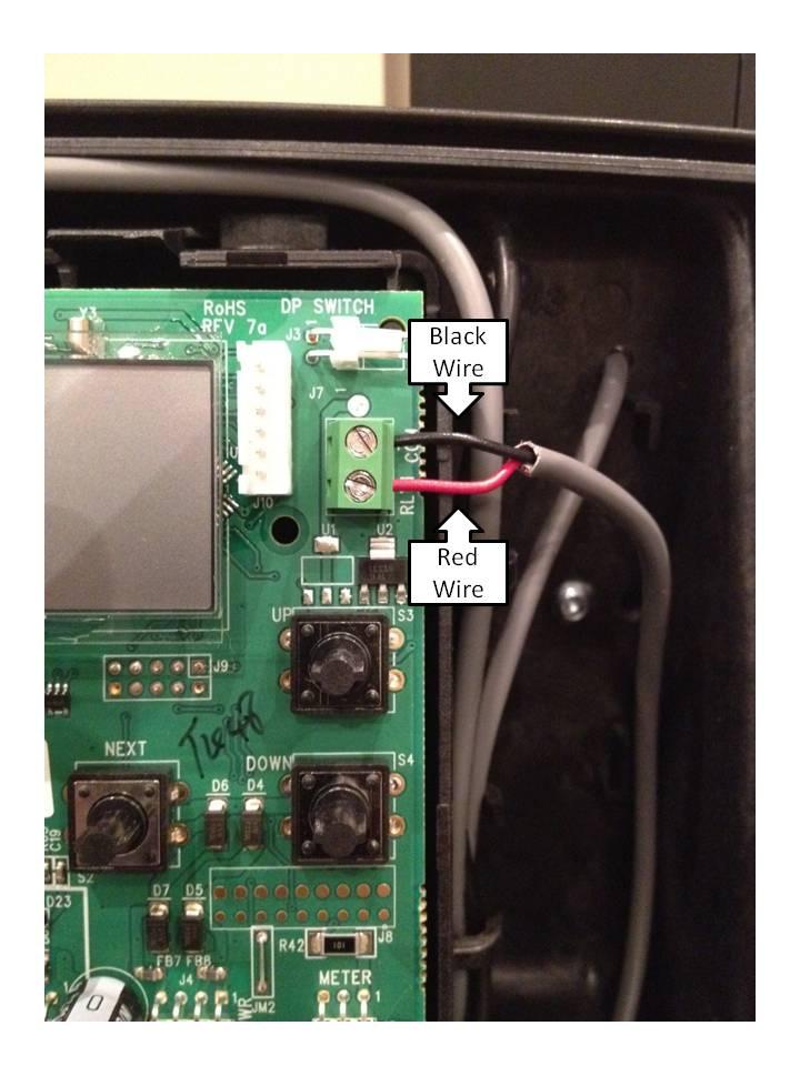
12 Factory Setup of Iron Blaster Iron Blaster setup of valve Valve set to FILTERING 1. Backwash cycle 15 minutes 2. Dn Brine cycle 30 minutes Setting the relay On time First relay at 17 minutes Second relay (Off) 27 minutes DAY OVERRIDE IS SET FOR 3 DAYS. Black wire = COM+ Red wire = RLY 1 12
13 13
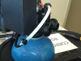
 Remove the CD Cell outlet tubing at the locations shown above. 2.) Disconnect the CD Cell H.V. wire from the frequency driver. 3.")
 Run warm water through the inlet tubing until the water from the outlet tubing runs clear and free or particulates. 5.")
14 CD Cell Inlet Port CD Cell Outlet Port CD Cell H.V. Wire Connection To Clean the CD Cell: 1.) Remove the CD Cell outlet tubing at the locations shown above. 2.) Disconnect the CD Cell H.V. wire from the frequency driver. 3.) Disconnect the CD Cell from its grounding clips and remove from generator. 4.) Run warm water through the inlet tubing until the water from the outlet tubing runs clear and free or particulates. 5.) Use compressed air to completely dry the interior and exterior of the CD Cell prior to re-installing. 6.) Re-install the CD Cell in reverse order of steps
15 15
16 Platinum Drawings and Part Numbers 16

17 Front Cover and Drive Assembly Drawing No. Order No. Description Quantity 1 CLK V WD1HS Front Cover Assembly 1 2 CLK V WD1 Motor 1 3 CLK V WD1 Drive Bracket & Spring Clip 1 4a CLK V3353HS WD1HS PC Board No Relay 4b CLK V3353HR WD1HR PC Board w/relay 1 5 CLK V3110 WD1 Drive Gear 12x CLK V3109 WD1 Drive Gear Cover 1 CLK V3186 WD1 AC ADAPTER 110V-12V Not Shown CLK V3186EU WD1 AC ADAPTER V-12V EU CLK V3186UK WD1 AC ADAPTER V-12V UK 1 CLK V WD1 AC ADAPTER CORD ONLY Relay Specifications: To insure proper fit and correct operation the following relay and relay socket manufactured by Idec or the exact equivalent should be used. Relay Socket Relay Idec Model and Description SH3B-05C 3 pole finger safe rail mount socket RH2LB-U-AC12V 12vac, DPDT magnetic latching relay The relay supplies 2 sets of dry contacts for user applications. The wiring of these contacts is application specific. Wiring For Correct On/Off Operation PC Board Relay Terminal Block Relay Socket Top #13 Center #12 and #14 Bottom #9 17

18 Drive Cap Assembly, Downflow Piston, Upflow Piston, Regenerant Piston and Spacer Stack Assembly Drawing No. Order No. Description Quantity 1 CLK V3005 WD1 Spacer Stack Assembly 1 2 CLK V3004 Drive Cap ASY 1 3 CLK V3343 WD1HS Drive Back Plate 1 4a CLK V3011* WD1 Piston Downflow ASY 4b CLK V301101* WD1 Piston Upflow ASY 1 5 CLK V3174 WD1 Regenerant Piston 1 6 CLK V3135 O-ring CLK V3180 O-ring CLK V3105 O-ring 215 (Distributor Tube) 1 Not Shown CLK V3001 CLK V CLK V3001UP CLK V300102UP WD1 Body ASY Downflow WD1 Mixing Valve Body ASY WD1 Body ASY Upflow WD1 Mixing Valve Body Upflow ASY *V3011 is labeled with DN and V is labeled with UP. Note: The regenerant piston is not used in backwash only applications. 1 18
19 Drive Cap Assembly, Downflow Piston, Regenerant Piston and Spacer Stack Assembly Drawing No. Order No. Description Quantity 1 CLK V3430 WD1.5 Spacer Stack Assembly 1 2 CLK V3004 Drive Cap ASY 1 3 CLK V3343 WD1HS Drive Back Plate 1 4 CLK V3407 WD1.5 Piston Downflow ASY 1 5 CLK V3174 WD1 Regenerant Piston 1 6 CLK V3135 O-ring CLK V3180 O-ring Not Shown CLK V3358 O-ring 219 (Distributor Tube Opening 1.32") CLK V3357 CLK V3020 CLK V CLK V CLK V Note: The regenerant piston is not used in backwash only applications. O-ring 218 (Distributor Tube Opening 32mm) WD1.25 Body ASY Downflow (Distributor Tube Opening 1.32") WD1.25 Mixing Valve Body Downflow ASY (Distributor Tube Opening 1.32") WD1.25 Body ASY Downflow (Distributor Tube Opening 32mm) WD1.25 Mixing Valve Body Downflow ASY (Distributor Tube Opening 32mm)
20 Injector Cap, Injector Screen, Injector, Plug and O-Ring Drawing No. Order No. Description Quantity 1 CLK V3176 Injector Cap 1 2 CLK V3152 O-ring CLK V3177 Injector Screen 1 4 CLK V30101Z WD1 Injector ASY Z Plug 1 CLK V30101A WD1 INJECTOR ASY A BLACK CLK V30101B WD1 INJECTOR ASY B BROWN CLK V30101C WD1 INJECTOR ASY C VIOLET CLK V30101D WD1 INJECTOR ASY D RED CLK V30101E WD1 INJECTOR ASY E WHITE 5 CLK V30101F WD1 INJECTOR ASY F BLUE 1 CLK V30101G WD1 INJECTOR ASY G YELLOW CLK V30101H WD1 INJECTOR ASY H GREEN CLK V30101I WD1 INJECTOR ASY I ORANGE CLK V30101J WD1 INJECTOR ASY J LIGHT BLUE CLK V30101K WD1 INJECTOR ASY K LIGHT GREEN Not Shown CLK V3170 O-ring 011 * Not Shown CLK V3171 O-ring 013 * * The injector plug and the injector each contain one 011 (lower) and 013 (upper) o-ring. Note: For upflow position, injector is located in the up hole and injector plug is in the other hole. WS1HR&HS upflow bodies are identified by having the DN marking removed. For a filter that only backwashes, injector plugs are located in both holes. 20
21 Refill Flow Control Assembly and Refill Port Plug Drawing No. Order No. Description Quantity 1 CLK V WD1 Refill Port Plug ASY This part is required for backwash only systems 2 CLK H4615 Elbow Locking Clip 1 3 CLK JCPP6 Polytube insert 3/8" 1 4 CLK JCPG6PBLK Nut 3/8" 1 5 CLK H4613 Elbow Cap 3/8" 1 6 CLK V3163 O-ring CLK V316501* WD1 RFC Retainer ASY 1 8 CLK V3182 WD1 RFC 1 Not Shown CLK H4650 Elbow ½" with nut and insert Option *Assembly includes WD1 RFC. 21
22 Drain Line 3/4 Drawing No. Order No. Description Quantity 1 CLK H4615 Elbow Locking Clip 1 2 CLK PKP10TS8BU Polytube insert 5/8 Option 3 CLK V3192 WD1 Nut ¾ Drain Elbow Option 4 CLK V WD1 Drain Elbow ¾ Male ASY 1 5 CLK V3163 O-ring CLK V WD1 DLFC Retainer ASY 1 CLK V WD1 DLFC 0.7 gpm for ¾ CLK V WD1 DLFC 1.0 gpm for ¾ CLK V WD1 DLFC 1.3 gpm for ¾ CLK V WD1 DLFC 1.7 gpm for ¾ CLK V WD1 DLFC 2.2 gpm for ¾ One DLFC CLK V WD1 DLFC 2.7 gpm for ¾ must be 7 CLK V WD1 DLFC 3.2 gpm for ¾ used if ¾" CLK V WD1 DLFC 4.2 gpm for ¾ fitting is CLK V WD1 DLFC 5.3 gpm for ¾ used CLK V WD1 DLFC 6.5 gpm for ¾ CLK V WD1 DLFC 7.5 gpm for ¾ CLK V WD1 DLFC 9.0 gpm for ¾ CLK V WD1 DLFC 10.0 gpm for ¾ Valves are shipped without drain line. ow control (DLFC) - install DLFC before using. Valves are shipped without ¾ nut for drain elbow (polytube installation only) and 5/8 polytube insert (polytube installation only). 22
23 Water Meter, Meter Plug and Mixing Valve Drawing No. Order No. Description Quantity 1 CLK V3151 WD1 Nut 1" QC 1 2 CLK V3003* WD1 Meter ASY 1 3 CLK V WD1 Turbine ASY 1 4 CLK V3105 O-ring CLK V WD1 Meter Plug ASY 1 6 CLK V3013 Mixing Valve Optional *Order number V3003 includes CLK V WS1 Turbine ASY and V3105 O-ring


24 Installation Fitting Assemblies Order No: CLK V3007 Description: WD1 Fitting 1" PVC Male NPT Elbow Assembly Order No: CLK V Description: WD1 Fitting ¾" & 1" PVC Solvent 90º ASY Drawing No. Order No. Description Quantity Drawing No. Order No. Description Quantity 1 CLK V3151 WD1 Nut 1" Quick Connect 2 1 CLK V3151 WD1 Nut 1" Quick Connect 2 2 CLK V3150 WD1 Split Ring 2 2 CLK V3150 WD1 Split Ring 2 3 CLK V3105 O-Ring CLK V3105 O-Ring CLK V3149 WD1 Fitting 1 PVC Male NPT Elbow 2 4 CLK V3189 WD1 Fitting ¾&1 PVC Solvent 90 2 Order No: CLK V Description: WD1 Fitting 1" Brass Sweat Assembly Order No: CLK V Description: WD1 Fitting ¾ " Brass Sweat Assembly Drawing No. Order No. Description Quantity Drawing No. Order No. Description Quantity 1 CLK V3151 WD1 Nut 1" Quick Connect 2 1 CLK V3151 WD1 Nut 1" Quick Connect 2 2 CLK V3150 WD1 Split Ring 2 2 CLK V3150 WD1 Split Ring 2 3 CLK V3105 O-Ring CLK V3105 O-Ring CLK V3188 WD1 Fitting 1 Brass Sweat Assy 2 4 CLK V WD1 Fitting ¾ Brass Sweat 2 24


25 Installation Fitting Assemblies Order No: CLK V Description: WD1 Fitting 1" Plastic Male NPT Assembly Order No: CLK V Description: WD1 Fitting 1-1/4" Plastic Male Assembly Drawing No. Order No. Description Quantity Drawing No. Order No. Description Quantity 1 CLK V3151 WD1 Nut 1" Quick Connect 2 1 CLK V3151 WD1 Nut 1" Quick Connect 2 2 CLK V3150 WD1 Split Ring 2 2 CLK V3150 WD1 Split Ring 2 3 CLK V3105 O-Ring CLK V3105 O-Ring CLK V3164 WD1 Fitting 1" Plastic Male NPT 2 4 CLK V3317 WD1 Fitting 1- ¼ Plastic Male NPT 2 Order No: CLK V Description: WD1 Fitting 1" Plastic Male NPT Assembly Order No: CLK V Description: WD1 Fitting 1-1/4" Plastic Male Assembly Drawing No. Order No. Description Quantity Drawing No. Order No. Description Quantity 1 CLK V3151 WD1 Nut 1" Quick Connect 2 1 CLK V3151 WD1 Nut 1" Quick Connect 2 2 CLK V3150 WD1 Split Ring 2 2 CLK V3150 WD1 Split Ring 2 3 CLK V3105 O-Ring CLK V3105 O-Ring CLK V3164 WD1 Fitting 1" Plastic Male NPT 2 4 CLK V3317 WD1 Fitting 1- ¼ Plastic Male NPT 2 25

26 Bypass Valve Drawing No. Order No. Description Quantity 1 CLK V3151 WD1 Nut 1" Quick Connect 2 2 CLK V3150 WD1 Split Ring 2 3 CLK V3105 O-Ring CLK V3145 WD1 Bypass 1" Rotor 2 5 CLK V3146 WD1 Bypass Cap 2 6 CLK V3147 WD1 Bypass Handle 2 7 CLK V3148 WD1 Bypass Rotor Seal Retainer 2 8 CLK V3152 O-ring CLK V3155 O-ring CLK V3156 O-ring (Not Shown) Order No. CLK V319101, Description: WS1 Bypass Vertical Adapter Assembly Order No. Description Quantity CLK V3151 WD1 Nut 1" Quick Connect 2 CLK V3150 WD1 Split Ring 2 CLK V3105 O-Ring CLK V3191 WD1 Bypass Vertical Adapter 2 26
 Although no tools are necessary to assemble or disassemble the valve, the WS1 wrench (shown in various positions on")
27 WS1 Wrench (Order No. CLK V319301) Although no tools are necessary to assemble or disassemble the valve, the WS1 wrench (shown in various positions on the valve) may be purchased to aid in assembly or disassembly. Econo Air Birm Installation Fitting Assemblies 27
28 Trouble Shooting Problem Follow up Action Sulphur coming through Check the amount of sulphur you are trying to remove it may be Set to everyday regeneration, 60 min draw too much to remove or low PH Iron coming through Same as above, ph of 6.8 or lower Same as above may require a ph filter Unit regenerating in Settings are incorrect Go to unit set for 2 am setting afternoon Not removing sulphur or iron Listen to back wash Overview 1) Check for obstruction in backwash, Check flow restrictor, Regenerate more often 2) Check the ozone generator is working 3) Clean the ozone tube Most service should be around the following: 1) Ozone is working 2) Brine draw is working sucking 3) Board is set right 4) Increase the ozone draw, backwash etc. 5) Check chemistry of water 6) PH should be 6.8 or higher 7) Obstruction in drain line 8) Did not install the back flow check valve 9) Setting for ozone to come properly programmed 10) By Pass is not open 11) Too much iron or sulphur for unit Error board flashing see manual for setting. 28
29 29
30 30
31 31
32 32
Superior Water And Air
 Superior Water And Air 80-974-9090 800-974-7638 OWNERS MANUAL Model 32-CL990 & 48-CL990 General Information Congratulations on having purchased a quality and well built Superior Water Softener. On a normal
General Operation. To set Time of Day. To set Time of Regeneration / Backwash
 1 General Operation When the system is operating one of two displays will be shown: time of day or days until the next regeneration. Pressing UP or DOWN will toggle between the two choices. To set Time
Superior Water And Air OWNER S MANUAL Model 32-CL770 & 48-CL770
 Superior Water And Air 80-974-9090 800-974-7638 OWNER S MANUAL Model 32-CL770 & 48-CL770 GENERAL INFORMATION Congratulations on having purchased a quality and well built Superior Water Softener. On a normal
Water Specialist 1 Control Valve Series Model: WS1TC 1.25 Control Valve Series Model: WS1.25TC
 Water Specialist Control Valve Series Model: WSTC.25 Control Valve Series Model: WS.25TC Operation and Instruction Manual for OEM Only. Please Note: This operation and instruction manual is for the training
Value Super Filter Max Installation Manual
 Value Super Filter Max Installation Manual Barrie, Ontario, Canada, L4N 4Y8 www.excaliburwater.com EXCALIBUR VALUE SUPER FILTER MAX INSTALLATION MANUAL INSTALLATION PROCEDURES: The Value Super Filter Max
Manual for Operation & Maintenance Of Metered Carbon Filter
 Industry Leader in RO Expertise and Membrane Applications since 1983 Manual for Operation & Maintenance Of Metered Carbon Filter for Models: W-G744EM W-G844EM W-G940EM W-G1054EM W-G1252EM W-G1354EM W-G1465EM
Watco Pro Series Water Conditioner
 Watco Pro Series Water Conditioner Operation & Maintenance Manual Marketed Exclusively By: Lee Supply Corp. 6610 Guion Road Indianapolis, IN 46268 800-873-1103 Page 2 Quick Reference Chart GENERAL OPERATION
Water Specialist WS1 and WS1.25 Drawings and Service Manual 1 Control Valve Series Model: WS Control Valve Series Model: WS1.
 Water Specialist WS1 and WS1.25 Drawings and Service Manual 1 Control Valve Series Model: WS1 1.25 Control Valve Series Model: WS1.25 Operation and Instruction Manual for OEM Only. Please Note: This operation
Model WS1 Demand. Operation & Maintenance Manual. 114 Vista Parkway Avon, IN New Aqua L.L.C.
 Model WS1 Demand Operation & Maintenance Manual 114 Vista Parkway Avon, IN 46123 317-272-6721 2008 New Aqua L.L.C. Page 2 Quick Reference Chart GENERAL OPERATION When the system is operating one of two
Installation and Service Manual Backwash Filter Systems
 Installation and Service Manual Backwash Filter Systems Ceramic Filters Co. Inc. 11617 Highway 124 Brooklyn, Michigan 49230 USA Technical Support: 800-427-7986 Email: eramic@frontiernet.net Page 1 Table
OWNER S MANUAL FOR ALL GREENSAND SYSTEMS
 OWNER S MANUAL FOR ALL GREENSAND SYSTEMS THIS MANUAL IS TO BE LEFT WITH THE OWNER OF THE EQUIPMENT FOR REFERENCE AND PURPOSES AND TECHNICAL GUIDANCE. IT IS STRONGLY RECOMMENDED THAT QUALIFIED DEALER SERVICE
SIMPLEX PREMIUM WATER SOFTENER INSTALLATION AND USER GUIDE
 SIMPLEX PREMIUM WATER SOFTENER INSTALLATION AND USER GUIDE 1 TABLE OF CONTENTS 1) Installation... 2 1.1) Pre-installation instructions... 2 1.2) General Installation and Service Warnings... 2 1.3) Site
Panel Operation Quick Reference Guide
 Panel Operation Quick Reference Guide Manual Regeneration (Backwash) Note:. If you need to initiate a manual regeneration, either immediately, or tonight at the preprogrammed time (typically 2 a.m.), complete
Water Specialist WS1 and WS1.25 Drawings and Service Manual 1 Control Valve Series Model: WS Control Valve Series Model: WS1.
 Water Specialist WS and WS.25 Drawings and Service Manual Control Valve Series Model: WS.25 Control Valve Series Model: WS.25 Operation and Instruction Manual for OEM Only. Please Note: This operation
Water Specialist 1 Control Valve Series Model: WS1CS 1.25 Control Valve Series Model: WS1.25CS
 Water Specialist 1 Control Valve Series Model: WS1CS 1.25 Control Valve Series Model: WS1.25CS Operation and Instruction Manual for OEM Only. Please Note: This operation and instruction manual is for the
Water Specialist 1 Control Valve Series Model: WS1CI 1.25 Control Valve Series Model: WS1.25CI
 Water Specialist 1 Control Valve Series Model: WS1CI 1.25 Control Valve Series Model: WS1.25CI Operation and Instruction Manual for OEM Only. Please Note: This operation and instruction manual is for the
WS1TC Series Installation and Operation Manual
 WS1TC Series Installation and Operation Manual Table of Contents Installation... 3 Bypass Valve... 4 Start-up Instructions... 6 General Information... 7 User Displays/Settings... 8 Installer Displays/Settings...
Installation Instructions & Owner s Manual LINDYSPRING LCR Series II Water Conditioners
 Installation Instructions & Owner s Manual LINDYSPRING LCR Series II Water Conditioners 115 N.W. Van Buren Topeka, KS 66603 Phone: 785-234-5551 Toll-free: 800-880-2022 Toll-free Fax: 800-269-3478 TABLE
Water Specialist CI Control Valve Programming and Cover Drawing Manual
 Water Specialist CI Control Valve Programming and Cover Drawing Manual Page 2 CI Man u al CI Man u al Page 3 Table of Contents CI Front Cover and Drive Assembly...4 OEM General Instructions...5 OEM Cycle
Water Specialist igen Control Valve Programming and Cover Drawing Manual
 Water Specialist igen Control Valve Programming and Cover Drawing Manual Page 2 igen Man u al igen Man u al Page 3 Table of Contents igen Front Cover and Drive Assembly...4 WS1 igen Drive Cap Assembly,
GF Series Water Softener
 GF Series Water Softener INSTALLATION, OPERATION, AND MAINTENANCE MANUAL COMPLETE FOR FUTURE REFERENCE: MODEL NO: SERIAL NO: DATE INSTALLED: DEALER: 8-569 G&F R2 LIMITED WARRANTY FOR WATER CONDITIONERS
7-LX B 7-LX B 7-LX B 7-LX B 7-LX B
 ESTATE SERIES INSTALLATION, OPERATING AND SERVICE MANUAL ELECTRONIC WATER SOFTENER WITH THE ¼ X-FACTOR CONTROL VALVE PROGRAMMED FOR PRE-FILL BRINING OPTION 7-LX5-00B 7-LX5-50B 7-LX5-00B 7-LX5-300B 7-LX5-00B
Water Specialist 1 Control Valve Series Model: WS Control Valve Series Model: WS1.25
 Water Specialist 1 Control Valve Series Model: WS1 1.25 Control Valve Series Model: WS1.25 Operation and Instruction Manual for OEM Only. Please Note: This operation and instruction manual is for the training
ADVANCE. Backwashing Filters and Tannin Filter. Installation Instructions & Owner s Manual
 ADVANCE Backwashing Filters and Tannin Filter Installation Instructions & Owner s Manual Ta b l e o f Co n t e n t s : Preinstallation Instructions Page 1 Bypass Valve Page 1-2 Installation Page 3-4 Sulfur
Water Specialist 1.5" CC Control Valve Programming and Drawings Manual
 Water Specialist 1.5" CC Control Valve Programming and Drawings Manual Page 2 WS 1.5 CC Man u al WS 1.5 CC Man u al Page 3 OEM General Instructions The control valve offers multiple procedures that allow
INSTALLATION, OPERATING AND SERVICE MANUAL ELECTRONIC WATER SOFTENER TIME CLOCK MODEL FEATURING THE 2002S VALVE
 INSTALLATION, OPERATING AND SERVICE MANUAL ELECTRONIC WATER SOFTENER TIME CLOCK MODEL FEATURING THE 00S VALVE 7-LECT-4 7-FESLECT-4 7-LET-4 7-FESLET-4 7-LET-3 7-FESLET-3 7-LET-45 7-FESLET-45 7-LET-60 7-FESLET-60
Water Specialist 1 Control Valve Series Model: WS Control Valve Series Model: WS1.25
 Water Specialist 1 Control Valve Series Model: WS1 1.25 Control Valve Series Model: WS1.25 Operation and Instruction Manual for OEM Only. Please Note: This operation and instruction manual is for the training
Water Specialist 1 Control Valve Series Model: WS1EI 1.25 Control Valve Series Model: WS1.25EI
 Water Specialist Control Valve Series Model: WSEI.25 Control Valve Series Model: WS.25EI Operation and Instruction Manual for OEM Only. Please Note: This operation and instruction manual is for the training
TABLE OF CONTENTS JOB SPECIFICATIONS
 IRONSOFT INSTALLATION, OPERATING AND SERVICE MANUAL ELECTRONIC IRONSOFT WATER SOFTENER WITH THE X-FACTOR CONTROL VALVE PROGRAMMED FOR PRE-FILL BRINING OPTION 7-FESLX-B 7-FESLX-B 7-FESLX-5B 7-FESLX-60B
OZONE ZENTEC CAPSULATE FILTER INSTALLATION AND USER GUIDE
 OZONE ZENTEC CAPSULATE FILTER INSTALLATION AND USER GUIDE 1 TABLE OF CONTENTS 1) Installation... 2 1.1) Pre-installation instructions... 2 1.2) General Installation and Service Warnings... 2 1.3) Site
wd-2
 wd-2 wd-4 wd-5 wd-6 wd-7 wd-8 wd-9 wd-10 wd-11 wd-12 wd-13 Part # Tank Size ( DxH ) Media Volume (ft3) Service Flow Rate (GPM) WD SP35BFJCT 10 x44 1.0 6.0 WD SP46BFJCT 10 x54 1.5 9.0 WD SP56BFJCT 10 x54
Water Specialist PR Control Valve Programming and Cover Drawing Manual
 Water Specialist PR Control Valve Programming and Cover Drawing Manual Page 2 PR Man u al PR Manual Page 3 Table of Contents PR Front Cover and Drive Assembly...4 OEM General Programming Instructions...5
TotalCare Series. Water Conditioners
 TotalCare Series Water Conditioners TABLE OF CONTENTS Preinstallation Instructions for Dealers............................3 Bypass Valve................................................3-4 Installation..................................................5-6
Water Specialist CK and EQ Control Valve Programming and Cover Drawing Manual
 Water Specialist CK and EQ Control Valve Programming and Cover Drawing Manual Page 2 CK and EQ Manual CK and EQ Manual Page 3 Table of Contents CK Front Cover and Drive Assembly...4 OEM General Programming
Consumer s Filter Manual. ProMate 6.0 Iron Curtain Junior Filter Manual
 ProMate 6.0 Iron Curtain Junior Filter Manual Consumer s Filter Manual Manufactured by: HELLENBRAND, INC. 404 Moravian Valley Road Waunakee, Wisconsin 53597 Web: www.hellenbrand.com Email: info@hellenbrand.com
3200ET TIMER. Service Manual. IMPORTANT: Fill in pertinent information on page 2 for future reference.
 3200ET TIMER Service Manual IMPORTANT: Fill in pertinent information on page 2 for future reference. Installation And Start-Up Procedures Timer Programming Water Hardness System Capacity Regeneration Time
INSTALLATION, OPERATING AND SERVICE MANUAL ELECTRONIC WATER FILTER TIME CLOCK MODEL FEATURING THE 2002F VALVE
 INSTALLATION, OPERATING AND SERVICE MANUAL ELECTRONIC WATER FILTER TIME CLOCK MODEL FEATURING THE 00F VALVE COLOR, TASTE, ODOR SEDIMENT/TURBIDITY 7-LETCT- 7-LETCT- 7-LETCT- IRON FILTER 7-LETIM- 7-LETIM-
NUGEN Pure Water Systems Fusion XT. Installation Instructions and Owners Manual
 NUGEN Pure Water Systems Installation Instructions and Owners Manual XT-48, XT-60, XT-70, XT-70ER, and XT-90 XT-32C Page 2 Page 3 Table of Contents Your Water Test...3 Pre-Installation Instructions...4
BNT 85 /185 Valve Operation Manual
 BNT 85 /185 Valve Operation Manual Note: 1. Read all instructions carefully before operation. 2. Avoid pinched o-rings during installation by applying (provided with install kit) NSF certified lubricant
Water Specialist WS1TT Drawings and Service Manual
 Water Specialist 2nd Tank Connection Port Treated Water Outlet Untreated Water Inlet In/Out Head 2nd Tank Connection Port Control Valve Proper installation shown above. See page 2 for issues that arise
7-LXC-50B 7-LXC-75B 7-LXC-100B 7-LX-75B 7-LX-100B 7-LX-150B 7-LX-200B 7-LX-300B
 INSTALLATION, OPERATING AND SERVICE MANUAL DIAMOND LINE LX ELECTRONIC WATER SOFTENER WITH THE XFACTOR CONTROL VALVE PROGRAMMED FOR PREFILL BRINING OPTION 7LXC50B 7LXC75B 7LXC00B 7LX75B 7LX00B 7LX50B 7LX00B
Owner s Filter Manual. ProMate 6.0 Iron Curtain Junior Filter Manual
 ProMate 6.0 Iron Curtain Junior Filter Manual Owner s Filter Manual Manufactured by: Hellenbrand, Inc. 404 Moravian Valley Road Waunakee, Wisconsin 53597 Phone: 608 849-3050 Fax: 608-849-7398 Web: www.hellenbrand.com
Water Specialist EI Control Valve Programming and Cover Drawing Manual
 Water Specialist EI Control Valve Programming and Cover Drawing Manual Page 2 EI Man u al EI Man u al Page 3 Table of Contents EI Front Cover and Drive Assembly... 4 Regeneration and Error Screens... 5
STORM. ProMate-6.0 Iron Curtain Storm Series
 STORM ProMate-6.0 Iron Curtain Storm Series Owner s Filter Manual Manufactured by: HELLENBRAND, INC. 404 Moravian Valley Road Waunakee, Wisconsin 53597 Web: www.hellenbrand.com Email: info@hellenbrand.com
WS1 & 1.25 Man u al. Introduction. The following general warnings and the specifications in Table 1 must appear in the OEM s System Manual.
 Page 4 WS1 & 1.25 Man u al Introduction This manual is about a control valve to be used on water softeners or water filters. The manual is designed to aid water treatment equipment manufacturers in the
Water Specialist EE Control Valve Programming and Cover Drawing Manual
 Water Specialist EE Control Valve Programming and Cover Drawing Manual Page 2 EE Man u al EE Man u al Page 3 Table of Contents EE Front Cover and Drive Assembly... 4 Regeneration and Error Screens, Button
Water Specialist 1 Control Valve Series Model: WS Control Valve Series Model: WS1.25
 Water Specialist Control Valve Series Model: WS.25 Control Valve Series Model: WS.25 Operation and Instruction Manual for OEM Only. Please Note: This operation and instruction manual is for the training
Water Specialist WS1TT Drawings and Service Manual
 Water Specialist HYDROCARBONS SUCH AS KEROSENE, BENZENE, GASOLINE, ETC., MAY DAMAGE PRODUCTS THAT CONTAIN O-RINGS OR PLASTIC COMPONENTS. EXPOSURE TO SUCH HYDROCARBONS MAY CAUSE THE PRODUCTS TO LEAK. DO
STORM. ProMate-6.0 Iron Curtain Storm Series
 STORM ProMate-6.0 Iron Curtain Storm Series Consumer s Filter Manual p/n 111701 Rev. C Updated 10/02/18 2018 Manufactured by: HELLENBRAND, INC. 404 Moravian Valley Road Waunakee, Wisconsin 53597 www.hellenbrand.com
Sanitizer Plus Series. Water Conditioners
 Sanitizer Plus Series Water Conditioners TABLE OF CONTENTS Preinstallation Instructions for Dealers............................3 Bypass Valve................................................3-4 Installation..................................................5-6
UF Series. Membrane Filtration System. Model CCUF-844
 UF Series Membrane Filtration System Model CCUF-8 TABLE OF CONTENTS Pre-installation Instructions for Dealers...3 Bypass Valve.... Installation....5 Programming Procedures... Start-up Instructions...3
IWT 565 Series Valve Operation Manual
 IWT 565 Series Valve Operation Manual Note: 1. Read all instructions carefully before operation. 2. Avoid pinched o-rings during installation by applying (provided with install kit) NSF certified lubricant
CareSoft. Series. Metered Water Softeners. For Models: UCS-844 UCS-948 UCS-1044 UCS-1054 UCS-1248 UCS-1354
 CareSoft Series Metered Water Softeners For Models: UCS-8 UCS-98 UCS-0 UCS-05 UCS-8 UCS-5 TABLE OF CONTENTS Pre-Installation Instructions for Dealers... Bypass Valve.... Installation.... 5-7 Programming
UF Series. Membrane Filtration System. Model CCUF-844
 UF Series Membrane Filtration System Model CCUF-844 TABLE OF CONTENTS Pre-installation Instructions for Dealers...3 Flushing Schedule...3 Bypass Valve....4 Installation.... 5-7 Programming Procedures...
MGTE Series 1 1/2 Metered & Time Clock
 INSTALLATION, OPERATION, AND MAINTENANCE MANUAL MGTE Series 1 1/2 Metered & Time Clock COMMERCIAL WATER CONDITIONERS COMPLETE FOR FUTURE REFERENCE: MODEL NO: SERIAL NO: DATE INSTALLED: DEALER: Marlo Incorporated
Service and Installation Guide
 Service and Installation Guide TM by AdEdge Technologies Inc. Medallion Series Arsenic Removal Systems Models: POE 5 1252 POE 7 1354 POE 10 1465 Arsenic Treatment Solutions Designed by: AdEdge Technologies,
Sanitizer Plus Series
 Sanitizer Plus Series Water Conditioners For Models: ASP-0 ASP-05 ASP-5 ASP-0 ASP-05 ASP-5 TABLE OF CONTENTS Pre-Installation Instructions for Dealers... Bypass Valve.... Installation.... 5 Programming
INSTALLATION, OPERATING AND SERVICE MANUAL
 INSTALLATION, OPERATING AND SERVICE MANUAL ECONO-mist WATER SOFTENER Demand Regeneration 7-LMC56-75B 7-LM56-75B 7-LM56-100B 7-LM56-150B 7-LM56-200B Congratulations on purchasing your new Lancaster Water
TTV Series. Softening Water System. Installation, Operation and Maintenance Manual. Revised 01/17/13
 TTV Series Softening Water System Installation, Operation and Maintenance Manual CAUTION: Read and Follow all safety rules and operating instructions before first use of product. DEALER NAME: DEALER PHONE
Impression Series. Installation Instructions & Owner s Manual. Metered Water Softeners
 Installation Instructions & Owner s Manual Impression Series Metered Water Softeners For Models: IM-844DUPURE IM-948DUPURE IM-1044DUPURE IM-1054DUPURE IM-1248DUPURE IM-1354DUPURE For Cabinet Models: IMC-835DUPURE
ProFloSE. Downflow Brining Service Manual. IMPORTANT: Fill in pertinent information on page 2 for future reference.
 ProFloSE Downflow Brining Service Manual IMPORTANT: Fill in pertinent information on page 2 for future reference. Job Specification Sheet Job Number Model Number Water Test Capacity Of Unit Max. Per Regeneration
65 Series. Valve Operation Manual
 65 Series Valve Operation Manual Note: 1. Read all instructions carefully before operation. 2. Avoid pinched o-rings during installation by applying (provided with install kit) NSF certified lubricant
Impression Plus Series
 Impression Plus Series Metered Water Softeners For Certified Models: IMP-844 IMP-948 IMP-044 IMP-054 IMP-248 IMP-354 Certified Cabinet Models: IMPC-835 IMPC-935 IMPC-035 TABLE OF CONTENTS Pre-Installation
Evolve ES Series. Water Softeners. For Models: ES-844 ES-948 ES-1044 ES-1248 ES-1354
 Evolve ES Series Water Softeners For Models: ES-8 ES-98 ES-0 ES-8 ES-5 TABLE OF CONTENTS Preinstallation Instructions for Dealers... Bypass Valve... Installation...5-6 Programming Procedures...7-8 Operating
Problem and Solutions Manual
 Problem and Solutions Manual By Caden Bird Table of Contents Table of Contents... iii Introduction... 5 Identifying the Problem... 7 Taking Apart the Valve... 13 Various Problems and Solutions... 23 Putting
Impression Plus Series
 Impression Plus Series Metered Water Softeners For Certified Models: IMP-8 IMP-98 IMP-0 IMP-05 IMP-8 IMP-5 Certified Cabinet Models: IMPC-85 IMPC-95 IMPC-05 TABLE OF CONTENTS Pre-Installation Instructions
Evolve ES Series. Water Softeners. For Models: ES-844 ES-948 ES-1044 ES-1248 ES-1354
 Evolve ES Series Water Softeners For Models: ES-844 ES-948 ES-1044 ES-1248 ES-1354 TABLE OF CONTENTS Preinstallation Instructions for Dealers.................................. 3 Bypass Valve.......................................................
AQT-56 POWERFLO SERIES SERVICE MANUAL CONTROL VALVES
 AQT-56 POWERFLO SERIES SERVICE MANUAL Table of Contents Products Checking List 3 General Residential Installation Check List 4 AQT-56ST Softener Timer Control Valve Start-up Procedures 5 AQT-56FT Filter
Owner s Manual HELLENBRAND, INC.
 Owner s Manual Manufactured by: HELLENBRAND, INC. 404 Moravian Valley Road Waunakee, Wisconsin 53597-2509 Phone: 608-849-3050 Fax 608-849-7398 Web: www.hellenbrand.com Email: info@hellenbrand.com 800160
MASTER. Water Conditioning Corp. Installation and Operation Manual. MCA Combination Series Residential Units
 MASTER Water Conditioning Corp. Installation and Operation Manual MCA Combination Series Residential Units February 2011 Table of Contents Page No. Topic Description 1 Model # and Packaging Packaging Information
AQT-56SE ELECTRONIC SERIES PROGRAMMING MANUAL CONTROL VALVES
 AQT-56SE ELECTRONIC SERIES PROGRAMMING MANUAL TABLE OF CONTENTS General Residential Installation 3 AQT-56SE Keypad 4 Control Operation 5 Master Programming - Setting the Time of Day 6 - Setting the Regeneration
Model 7000XTR. Service Manual. IMPORTANT: Fill in Pertinent Information on Page 3 for Future Reference
 Model 7000XTR Service Manual IMPORTANT: Fill in Pertinent Information on Page 3 for Future Reference Table of Contents Job Specification Sheet 3 Water Softener Control Valve 4 Valve Installation and Start-Up
Installation Instructions & Owner s Manual. Omega Series Metered Water Softeners
 Installation Instructions & Owner s Manual Omega Series Metered Water Softeners TABLE OF CONTENTS Preinstallation Instructions for Dealers............................3 Bypass Valve................................................3-4
FLECK 5800 LXT DOWNFLOW/UPFLOW SERVICE MANUAL
 FLECK 5800 LXT DOWNFLOW/UPFLOW SERVICE MANUAL 2013 Pentair Residential Filtration, LLC www.pentairaqua.com/pro TABLE OF CONTENTS JOB SPECIFICATION SHEET... 2 INSTALLATION... 3 START-UP INSTRUCTIONS...
UF Series. Twin Membrane Filtration System. Model CCUF-844TW
 UF Series Twin Membrane Filtration System Model CCUF-844TW TABLE OF CONTENTS Pre-Installation Instructions for Dealers...3 Bypass Valve....4 Installation....5 Programming Procedures...7 Start-up Instructions...9
Impression Plus Series
 Impression Plus Series Metered Water Softeners For Certified Models: IMP-844 IMP-948 IMP-1044 IMP-1054 IMP-1248 IMP-1354 Certified Cabinet Models: IMPC-835 IMPC-935 IMPC-1035 TABLE OF CONTENTS Pre-Installation
H-125 HE SERIES. Owner s Manual HIGH EFFICIENCY SYSTEM. Manufactured by: HELLENBRAND, INC. Web:
 H-125 HE SERIES HIGH EFFICIENCY SYSTEM Owner s Manual p/n 800679 Rev. C Updated 10/02/18 2016-2018 Manufactured by: HELLENBRAND, INC. Web: www.hellenbrand.com Email: info@hellenbrand.com This owner s manual
Water Specialist WS2H and WS3 Control Valve Manual
 Water Specialist WS2H and WS3 Control Valve Manual HYDROCARBONS SUCH AS KEROSENE, BENZENE, GASOLINE, ETC., MAY DAMAGE PRODUCTS THAT CONTAIN O-RINGS OR PLASTIC COMPONENTS. EXPOSURE TO SUCH HYDROCARBONS
FLECK 5800 LXT DOWNFLOW/UPFLOW SERVICE MANUAL
 FLECK 5800 LXT DOWNFLOW/UPFLOW SERVICE MANUAL waterpurification.pentair.com TABLE OF CONTENTS JOB SPECIFICATION SHEET... 2 INSTALLATION... 3 START-UP INSTRUCTIONS... 4 CONTROL FEATURES... 4 CONTROL OPERATION...
Installation and Operations Manual
 Excalibur Water Systems 3.0 High Capacity Superflow Series QUADPLEX Water Softener Installation and Operations Manual 142 Commerce Park Drive, Units M-O, Barrie ON L4N 8W8 www.excaliburwater.com Water
WS2H/ WS3 Error Codes
 WS2H & WS3 Troubleshooting Page 1 WS2H/ WS3 Error Codes Possible Errors Code Description 1001 No Encoder Pulses 1002 Unexpected Stall, Main Drive 1003 Run Time To Long, Main Drive 14001 Message Queue Full
SmartChoice. Gen II itwin. Water Conditioning System. Installation, Operation, and Maintenance Manual. Installation, Operation, and Maintenance Manual
 SmartChoice TM Gen II itwin Water Conditioning System > > CLOCK REGEN NEXT Installation, Operation, and Installation, Operation, and 7785 East US Hwy 36 Avon, IN 46123 (317) 272-3000 (800) 447-5582 For
Impression Series Impression Plus Series
 Impression Series Impression Plus Series Water Filters For Models: IMS-05 IMS-8 IMS-5 IMFE-05 IMFE-8 IMFE-5 IAG-05 IAG-8 IAG-5 IACG-05AN IACG-8AN IACG-5AN IMBF-0 IMBF-05 IMBF-5 IMBF-0MAN IMBF-05MAN IMBF-5MAN
Water Specialist WS2H and WS3 Control Valve Drawings and Service Manual
 Water Specialist WSH and WS Control Valve Drawings and Service Manual HYDROCARBONS SUCH AS KEROSENE, BENZENE, GASOLINE, ETC., MAY DAMAGE PRODUCTS THAT CONTAIN O-RINGS OR PLASTIC COMPONENTS. EXPOSURE TO
6700XTR Upflow. Service Manual. IMPORTANT: Fill in Pertinent Information on Page 3 for Future Reference
 6700XTR Upflow Service Manual IMPORTANT: Fill in Pertinent Information on Page 3 for Future Reference IMPORTANT: Fill in Pertinent Information on Page 3 for Future Reference Table of Contents Job Specification
Control Valves, Fittings and Accessories
 Control Valves, Fittings and Accessories NEW WS1EE TWIN ALTERNATING CONTROL VALVE 28 gpm WS2H 125 gpm WS 250 gpm WS1.5EE WS1.5SP 70 gpm WS2EE WS2SP 115 gpm WS2EE/QC* WS2SP/QC* 125 gpm WS1.25* WS1.25CS*
AQT-275 SERIES SERVICE MANUAL CONTROL VALVES
 AQT-275 SERIES CONTROL VALVES SERVICE MANUAL Table of Contents General Residential Installation 3 Valve Start-up Procedures 4 Regeneration Cycle Program Setting Procedures 5 Water Conditional Diagrams
ONE. Cartridge Tank Filters
 ONE Cartridge Tank Filters TABLE OF CONTENTS Preinstallation Instructions....3 EF-835-1 Bypass Installation...3 Installation Instructions....5 Cartridge Replacement Instructions....7 EF-835-2 Installation
Control Valves, Fittings and Accessories
 Control Valves, Fittings and Accessories NOW WITH BATTERY PACK OPTION WS1EE TWIN ALTERNATING CONTROL VALVE 28 gpm WS2H 125 gpm WS 250 gpm WS1.5EE WS1.5SD/SP 70 gpm WS2EE WS2SD/SP 115 gpm WS2EE/QC* WS2SP/QC*
Water Specialist 1.5, 2 and 2 QC Control Valve Drawings and Service Manual
 Water Specialist.5, and QC Control Valve ings and Service Manual HYDROCARBONS SUCH AS KEROSENE, BENZENE, GASOLINE, ETC., MAY DAMAGE PRODUCTS THAT CONTAIN O-RINGS OR PLASTIC COMPONENTS. EXPOSURE TO SUCH
DCS7 Water Softener - Product Manual
 pg. 0 Set Up Instructions for DCS7 Water Softener Inspect the packaging of the equipment to confirm that nothing was damaged during shipping. (Figure 1) Remove the resin tank(s) and valve(s) from the packaging.
Owner s Manual. Manufactured by: HELLENBRAND, INC. 404 Moravian Valley Road Waunakee, Wisconsin
 System for Automatic Discharge Management - U.S. Patent No. 9,862,619 Method of Water Discharge Management - U.S. Patent No. 9,346,689 B2 Owner s Manual Manufactured by: HELLENBRAND, INC. 404 Moravian
Impression Plus Series Sanitizer Plus Series
 Impression Plus Series Sanitizer Plus Series Twin Water Softeners For Models: IMP-8TW IMP-0TW IMP-05TW IMP-5TW IMP-65TW IMP-665TW IMPRC-05TW IMPRC-5TW ASP-0TW ASP-05TW ASP-5TW ASP-65TW ASP-665TW ASP-0TW
Trouble Shooting Guide for WS1 - WS2 Control Valves
 Trouble Shooting Guide for WS1 - WS2 Control Valves Page 2 Trouble Shooting Guide for WS1 - WS2 Control Valves 1. No Display on Troubleshooting TC control valves do not have meters so shaded ares are not
Owner s Manual AMERICAN AQUA Saline, MI (734) Howell, MI (517) Adrian, MI (517)
 Howell, MI (517) Adrian, MI (517)") Owner s Manual 2008-2009 AMERICAN AQUA Saline, MI (734)429-5070 Howell, MI (517)546-1750 Adrian, MI (517)265-8000 www.americanaqua.com This owner s manual is designed to assist owners and installers with
Owner s Manual 2008-2009 AMERICAN AQUA Saline, MI (734)429-5070 Howell, MI (517)546-1750 Adrian, MI (517)265-8000 www.americanaqua.com This owner s manual is designed to assist owners and installers with
Owner s Manual. H151 HE - High Efficiency Water Softening System
 H151 HE - High Efficiency Water Softening System Owner s Manual Manufactured by: HELLENBRAND, INC. 404 Moravian Valley Road Waunakee, Wisconsin 53597-2509 Web: www.hellenbrand.com Email: info@hellenbrand.com
5900e Carbon Filter Installation & Start-Up Guide
 Clean Water Made Easy www.cleanwaterstore.com 5900e Carbon Filter Installation & Start-Up Guide Thank you for purchasing a Clean Water System! With proper installation and a little routine maintenance
Series. Ion Pro and CareClear Pro. Water Filters. For Models: IPHS IPFE IPG IPCG-AN CCP CCP-AN
 Ion Pro and CareClear Pro Water Filters Series For Models: IPHS IPFE IPG IPCG-AN CCP CCP-AN TABLE OF CONTENTS Pre-Installation Instructions for Dealers... Bypass Valve.... 4 Installation....5-7 Programming
ONE. Cartridge Tank Filters
 ONE Cartridge Tank Filters TABLE OF CONTENTS Preinstallation Instructions...................................... 3 Bypass Installation for EF-835-1................................ 3-4 Bypass Installation
Model 5600SXT Downflow
 Model 5600SXT Downflow Service Manual Distributed By: IMPORTANT: Fill in Pertinent Information on Page 3 for Future Reference 2325 Cousteau Ct. Vista, CA 92081 (760) 727-3711 (760) 727-4427 www.appliedmembranes.com