BEARING AND LINEAR REPLACEMENT GUIDE
|
|
|
- Annabel Brooks
- 5 years ago
- Views:
Transcription


1 BEARING AND LINEAR REPLACEMENT GUIDE SUBSCRIBE TO NSK NEWSLETTER
2
3 Table of Contents Introduction The NSK Brand... Page A-1 Terminology... Page A-2 Types and Performance... Page A-3 Precision Class... Page A-4 Identification... Page A-5 How to Order Replacement s... Page A-9 Cylindrical Roller s Nomenclature... Page C-1 Applications... Page C-1 Interchange... Page C-2 Internal Clearance... Page C-3 Tables... Page C-5 Ball s Single Row Deep Groove Ball s Nomenclature... Page B-1 Interchange... Page B-2 Applications... Page B-2 Features... Page B-3 Internal Clearance... Page B-4 Snap Ring and Groove Dimensions... Page B-5 Tables... Page B-7 Double Row Angular Contact Ball s Nomenclature... Page B-23 Interchange... Page B-24 Applications... Page B-24 Tables... Page B-25 Self-Aligning Ball s Nomenclature... Page B-31 Applications... Page B-31 Interchange... Page B-32 Internal Clearance... Page B-32 Tables... Page B-33 Angular Contact Ball s Nomenclature... Page B-37 Interchange... Page B-38 Applications... Page B-38 Spherical Roller s Spherical Roller s Nomenclature... Page D-1 Interchange... Page D-2 Applications... Page D-2 Internal Clearance... Page D-3 Tables... Page D-5 Shaker Screen s Nomenclature... Page D-39 Internal Clearance... Page D-39 Interchange... Page D-40 Tables... Page D-41 Tapered Roller s Metric Tapered Roller s Nomenclature... Page E-1 Interchange... Page E-2 Applications... Page E-2 Tables... Page E-3 Inch Tapered Roller s Nomenclature... Page E-29 Interchange... Page E-30 Applications... Page E-30 Tables... Page E-31 Tables... Page B-39
4 Table of Contents (cont.) Thrust s Super Precision s (cont.) Ball Thrust s Nomenclature... Page F-1 Interchange... Page F-2 Applications... Page F-2 Tables... Page F-3 Spherical Roller Thrust s Nomenclature... Page F-11 Interchange... Page F-12 Applications... Page F-12 Tables... Page F-13 Tapered Roller Thrust s Nomenclature... Page F-19 Applications... Page F-19 Tables... Page F-19 Cylindrical Roller Thrust s Nomenclature... Page F-20 Applications... Page F-20 Tables... Page F-21 Split Pillow Blocks Nomenclature... Page G-1 Applications... Page G-2 Accessories... Page G-2 Tables... Page G-3 Inch Adapter Sleeves... Page G-29 Inch Lock Nuts and Washer... Page G-32 Super Precision s Super Precision Angular Contact Ball s Nomenclature... Page H-1 Interchange... Page H-2 Super Precision Angular Contact Ball s (cont.) Applications...Page H-2 Tables...Page H-3 High Speed Super Precision Angular Contact Ball s Nomenclature...Page H-15 Interchange...Page H-16 Applications...Page H-16 Recommended Grease Quantities...Page H-18 Tables...Page H-19 Super Precision Angular Contact Thrust Ball s Nomenclature... Page H-39 Interchange... Page H-40 Applications... Page H-40 Tables... Page H-41 Super Precision Cylindrical Roller s Nomenclature... Page H-45 Interchange... Page H-46 Applications... Page H-46 Tables... Page H-47 Ball Screw Support s Nomenclature... Page H-53 Interchange... Page H-54 Applications... Page H-54 Major Dimensions... Page H-55 Load Ratings... Page H-56 Preloads... Page H-57 Precision Deep Groove Ball s Nomenclature... Page H-58 Interchange... Page H-58 Applications... Page H-58 Tables... Page H-59
5 Linear Motion Linear Guides Applications... Page I-1 Product Selection Tips... Page I-2 Interchange... Page I-3 Types... Page I-5 NH Series (Replacement for LH Series, Size 15-65) Nomenclature... Page I-7 AN, BN Models... Page I-9 AL, BL Models... Page I-11 EM, GM Models... Page I-13 NS Series (Replacement for LS Series) Nomenclature... Page I-15 CL, AL Models... Page I-17 JM, EM Models... Page I-19 PU Series PE Series Nomenclature... Page I-21 TR, AR, AL, UR, BL Models... Page I-23 Nomenclature... Page I-25 AR, TR, UR, BR Models... Page I-27 LW Series Nomenclature... Page I-29 EL Model... Page I-31 RA Series Nomenclature... Page I-33 AN, BN Models... Page I-35 AL, BL Models... Page I-37 EM, GM Models... Page I-39 Assembly and Mounting... Page I-41 Grease... Page I-43 K1 Maintenance-Free Lubrication System... Page I-47 Unit Conversions... Page I-52 Precision Ground Ball Screw Nomenclature... Page I-53 Specification Sheet for New Applications... Page I-54 Compact FA Quickship Ball Screws Features... Page I-55 Availability... Page I-56 Rolled Ball Screw Nomenclature... Page I-57 Product Classification... Page I-58 Ball Screw Support Units Nomenclature... Page I-59 Categories... Page I-60 Support Units for Light Load... Page I-61 Support Units for Heavy Load... Page I-61 Support Units for Light Load... Page I-62 and Small Equipment Monocarrier Features... Page I-63 Applications... Page I-64 MCM Series Monocarrier Nomenclature... Page I-65 Applications... Page I-65 Accuracy Grade and Limitations... Page I-66 Standard Combinations of Stroke... Page I-67 and Ball Screw Lead Basic Load Rating... Page I-68 MCH Series Monocarrier Nomenclature... Page I-69 Applications... Page I-69 Accuracy Grade and Limitations... Page I-70 Standard Combinations of Stroke... Page I-71 and Ball Screw Lead Basic Load Rating... Page I-72
6 Table of Contents (cont.) Engineering Selection... Page J-1 Tolerances... Page J-5 Tolerances for Shaft Diameters... Page J-19 Tolerances for Housing Bore Diameters... Page J-21 Fits and Internal Clearance... Page J-23 How to Select a Proper Fit... Page J-24 Changes in Internal Radial Clearance... Page J-28 Preloaded s... Page J-29 Lubricants... Page J-32 Lubrication... Page J-35 How to Handle s... Page J-42 Mounting Factors to Consider... Page J-42 Inspecting and Troubleshooting... Page J-48 How to Dismount s... Page J-49 Cleaning, Inspection, Evaluation and Maintenance... Page J-51 Failures... Page J-52 Conversion Factors... Page J-54
7


8 INTRODUCTION
9 Table of Contents The NSK Brand... Page A-1 Terminology... Page A-2 Types and Performance... Page A-3 Precision Class... Page A-4 Identification... Page A-5 How to Order Replacement s... Page A-9 INTRODUCTION
10 The NSK Brand, Recognized Around the World From home appliances, automobiles, and capital equipment to the aerospace industry NSK bearings are used in an extensive range of applications. NSK established its global-scale enterprise on technology that has met the exact requirements of global industry. We have also established R&D systems and support services to meet the diverse needs of our customers on every continent. As a brand recognized around the world, NSK continues to lead industry with its technical expertise. NSK is on the Move, Across the Globe Headquarters Technical Offices Plants Sales Offices America America America (North) Europe Africa Asia Europe Ann Arbor Ann Arbor Ann Arbor Kielce Johannesburg Anshun Barcelona Bennington Munderkingen Bangkok Düsseldorf Asia Asia Clarinda Newark America (North) Beijing Istanbul Shanghai Kunshan Franklin Peterlee Ann Arbor Chengdu Leipzig Singapore Liberty Torino Atlanta Chennai Maidenhead Europe Bennington Guangzhou Milano Europe Kielce America (South) Japan Chicago Hongkong Newark Maidenhead Newark Suzano Fujisawa Indianapolis Jakarta Paris Ratingen Hanyu Los Angeles Johor Bahru Stuttgart Japan Asia Haruna Miami Kota Kinabalu Tilburg Tokyo Japan Anshun Konan Montreal Kuala Lumpur Warsaw Fujisawa Balakong Otsu San Jose Manila Maebashi Chachoengsao Maebashi Toronto Prai Japan Changshu Takasaki Vancouver Seoul Nagoya Changwon Tanakura Shanghai Tokyo Chennai Ukiha America (South) Singapore Chonburi Belo Horizonte Taichung Australia Dongguan Buenos Aires Tainan Adelaide Jakarta Joinville Taipei Auckland Kunshan Mexico City Brisbane Suzhou Porto Alegre Melbourne Zhangjiagang Recife Perth São Paulo Sydney A-1 INTRODUCTION
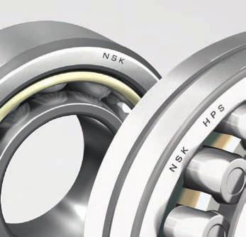
11 Terminology Design and Classification Rolling bearings use balls or rollers, located between bearing rings, to minimize friction. The rolling elements are separated and held in position by cages. The construction of six of the most common rolling element bearings are illustrated here for identification of nomenclature. Specific dimensions and details for these bearings are given in the dimensional tables in the following sections of this catalog. Width Width Outside Diameter Outer Ring Raceway Locating Snap Ring Outer Ring Cage Ball Inner Ring Bore Diameter Inner Ring Raceway Shield or Seal Chamfer Dimension Cage Inner Ring Back Face Outer Ring Back Face Contact Angle Outer Ring Ball Inner Ring Effective Load Center Inner Ring Front Face Outer Ring Front Face Cage Outer Ring Cylindrical Roller Inner Ring Inner Ring Unflanged Shoulder Outer Ring Flanged Shoulder Single Row Deep Groove Ball Single Row Angular Contact Ball Cylindrical Roller (NU Style) Width Lube Groove & Oil Holes Cage Roller Angle Tapered Roller Cage Spherical Roller Cup Angle Cone Front Face Cup Back Face Cup Width Cone Width Effective Load Center Cone Back Face Cup Front Face Cup Tapered Bore Straight Bore Floating Guide Ring Inner Ring Outer Ring Cage Outer Ring Ball Inner Ring Bore Diameter Height Outer Ring Bore Diameter Outer Ring Diameter Tapered Roller Spherical Roller Single Direction Thrust Ball INTRODUCTION A-2
12 Types and Performance Type Radialbelastungebelastungen Belastungen Series Radial Radial- Kombinierte Loads Radialbelastungen Axiallasten Axiallasten Loads Hohe Kombinierte Combined Hohe Kombinierte Axiallasten High Speeds Drehzahlen Belastungen Loads Winkelabweichung Drehzahlen Belastungen Hohe Angular Winkelabweichung Drehzahlen Misalignment Winkelabweichung Lagertyp SerieLagertyp Deep Groove Ball Double Row 6900-BL Deep Groove Ball Angular Contact Ball Serie Skizze Serie Skizze BL Good Good Skizze Fair 2 directions Ausreichend Ausreichend in in Gut beide Exzellent in Gut beide Richtungen Richtungen Fair 2 directions Good 1 direction only Good Excellent Fair Exzellent Gut Exzellent Gut Fair Fair Poor Ausreichend Rillenkugellager Rillenkugellager Gut in beide Gut 6900-BL 6900-BL 6900-BL Richtungen Ausreichend Ausreichend Ausreichend Zweireihiges Zweireihiges in Rillenkugellager Gut in beide Aus Gut in beide Ausreichend Ausreichend Richtungen Good Ausreichend Schwach Excellent Ausreichend Schwach Rillenkugellager Gut in beide Aus Richtungen Good Richtungen Poor Gut Schwach Double Row Angular Contact Ball Good 2 directions Good Good Fair Poor Schrägkugellager Gut in in eine Schrägkugellager Gut in eine Gut in eine Gut Gut Gut Exzellent Gut Exzellent Schwach Gut Exzellent Schwach Schwach Richtung Richtung Richtung Four-Point Contact Ball Self-Aligning Ball Cylindrical Roller Cylindrical Roller Cylindrical Roller Tapered Roller Spherical Roller QJ200-QJ300 Poor Fair NU-N NJ-NF NUP HR DJ Good 2 directions Poor 2 directions Fair Good Poor Zweireihiges Zweireihiges Gut in beiden Gut in in beiden Gut in beiden Schrägkugellager Schrägkugellager Gut Gut Gut Ausreichend Gut Ausreichend Schwach Gut Ausreichend Schwach Schwach Richtungen Richtungen Richtungen Vierpunkt- QJ200-QJ300 Vierpunkt- QJ200-QJ300 QJ200-QJ300 Schrägkugellager Schrägkugellager Schwach Poor Good Excellent Gut in beiden Gut Ausreichend Richtungen Gut reichend Schwach Gut reichend Gut Schwach in in beiden Gut in Aus- beiden Aus- Richtungen Schwach Richtungen Schwach Schwach Good None None Excellent Poor Good Good Good Richtungen Excellent Fair 1 direction only Fair 2 directions Good 1 direction only Fair 2 directions Fair Good Poor Pendelkugellager Pendelkugellager Ausreichend in beiden Schwach Gut Exzellent Schwach Aus- Schwach Ausreichend in beiden Schwach Gut Exzellent Schwach in reichend in beiden Schwach Gut Exzellent Richtungen Richtungen Richtungen Kann keine Kann keine Kann keine Zylinder- NU-N Zylinderrollenlager aufnehmen aufnehmen NU-N NU-N Gut Axiallasten Gut Axiallasten Ohne Gut Axiallasten Exzellent Ohne Ausreichend Exzellent Ohne Ausreichend Exzellent Ausreichend rollenlager aufnehmen Ausreichend Zylinderrollenlager Gut in eine Gut rollenlager NJ-NF Zylinder- NJ-NF NJ-NF Richtungen Ausreichend Zylinderrollenlager rollenlager NUP Zylinder- NUP NUP Gut in beide Gut Fair Good Poor Ausreichend Ausreichend Ausreichend Gut in eine Ausreichend Gut Ausreichend Gut Ausreichend Gut Ausreichend in Aus- in eine Richtungen Richtungen Good Fair Poor Ausreichend Ausreichend in Ausreichend Richtungen reichend Gut Good Ausreichend Gut Fair Ausreichend Gut Excellent in beide Aus- Gut in beide Aus- Richtungen Ausreichend HR HR HR Kegelrollenlager 30300DJ Kegelrollenlager Thrust 30300DJ Ball 30300DJ Gut Gut Richtung Gut None in eine Good 1 direction only Gut in in eine Gut in None eine Poor None Gut Ausreichend Gut Ausreichend Gut Ausreichend Ausreichend Richtung Richtung Ausreichend Pendelrollenlager Pendelrollenlager Exzellent in Exzellent beide Richtungen A-3 INTRODUCTION Ausreichend Ausreichend Exzellent in in Gut beide Richtungen Ausreichend in Gut beide Richtungen Ausreichend Exzellent Gut Ausreichend Exzellent Exzellent
13 Precision Class Tolerance Standards The dimensional and running accuracies of rolling bearings are standardized by ISO with regard to the following items: Tolerances for bore diameter, outer diameter, individual ring width, and overall width Tolerances for absolution dimensions of inscribed circle diameter and circumscribed circle diameter Tolerances for chamfer dimension Tolerances for width variations Tolerances for taper angle and taper bore diameters Tolerances for radial runout of inner ring and outer rings Tolerances for axial runout of inner and outer rings Tolerances for side or face runout of inner ring Tolerances for side or face runout of outer ring Precision Standards Equivalent Standards (reference) ANSI/ABMA (3) JIS (1) Class 0 Class 6 Class 5 Class 4 Class 3 Class 2 DIN (2) P0 P6 P5 P4 P3 P2 Ball s ABEC 1 ABEC 3 ABEC 5 ABEC 7 ABEC 7/9 ABEC 9 (CLASS 5P) (CLASS 7P) (CLASS 9P) Roller s RBEC 1 RBEC 3 RBEC 5 Tapered Roller s CLASS 4 CLASS 2 CLASS 3 CLASS 0 CLASS 00 (1) JIS: Standards for Japanese Industry, (2) DIN: German Institute for Standards, (3) ABMA: American Manufacturers Association. Standard s Precision Standard for Precision s INTRODUCTION A-4
14 Identification Formulation s are identified by numbers and letters which designate bearing type, boundary dimensions, tolerance class, internal clearance and other specifications. The numbers used for standard bearings conform to ISO 15, Designation of Rolling s. Boundary dimensions for the most commonly used bearings are based on the ISO Boundary Dimensions Tables. In order to establish certain standards in addition to those specified in ISO, NSK also uses various designations of its own. Single Row Deep Groove Ball Single Row Angular Contact Ball Self-Aligning Ball Single Row Cylindrical Roller Double Row Cylindrical Roller Metric Tapered Roller Spherical Roller Thrust Ball with Flat Seat Spherical Roller Thrust Series Type Dimension Series Width* Series Diameter Series 68 6 (1) (1) (1) (0) (0) (0) (1) (0) (0) (0) (0) (0) (2) (2) 3 NU10 NU 1 0 NU2 NU (0) 2 NU22 NU 2 2 NU3 NU (0) 3 NU23 NU 2 3 NU4 NU (0) 4 NJ2 NJ (0) 2 NJ22 NJ 2 2 NJ3 NJ (0) 3 NJ23 NJ 2 3 NJ4 NJ (0) 4 N2 N (0) 2 N3 N (0) 3 N4 N (0) 4 NF2 NF (0) 2 NF3 NF (0) 3 NF4 NF (0) 4 NNU49 NNU 4 9 NN30 NN (0) ** A-5 INTRODUCTION *The width series numbers shown in parentheses are usually omitted. **213 is customary usage since this series would be 203 according to standard practice.
15 Formulation (cont.) series numbers indicate bearing types and dimension series. They constitute the basic number structure for bearing designations. These are shown on page A-7. Supplementary symbols and meanings of typical numbers and symbols are shown on page A-8. Typical examples of bearing designations are illustrated below: ZZ C3 Radial clearance (C3) Shields on Both Sides Bore (40mm) Diameter Series 3 Single Row Deep Groove Ball K + H206 Adapter with 25mm Bore Tapered Bore (1:12 Taper) Bore (30mm) Diameter Series 2 Self-Aligning Ball NU 3 18 M () Radial Clearance (Blank is CN) Machined Brass Cage Bore (90mm) Diameter Series 3 Cylindrical Roller (NU Type) NN K CC1 P4 Tolerance to ISO Class 4 Radial Clearance for Matched Cylindrical Roller s Tapered Bore (1:12 Taper) Bore (85mm) Diameter Series 0 Width Series 3 Cylindrical Roller (NN Type) A DB C3 Axial Clearance (C3) Back-to-Back Arrangement Contact Angle (30 ) Bore (100mm) Diameter Series 2 Single Row Angular Contact Ball HR J Small Diameter of Outer Ring Raceway and Contact Angle Conform to ISO Standard Bore (35mm) Diameter Series 2 Width Series 0 Tapered Roller High Capacity /1000 M K30 E4 C3 Radial Clearance (C3) Outer Ring with Lubrication Groove and Holes Tapered Bore (1:30 Taper) Machined Brass Cage Bore (1,000mm) Diameter Series 0 Width Series 4 Spherical Roller Bore (75mm) Diameter Series 2 Height Series 1 Thrust Ball INTRODUCTION A-6
16 Identification (cont.) Formulation of s Series Series Z ZZ DU DDU V VV Basic Bore Contact Angle Internal Design Material Cage Seals, Shields Seals, Shields Shield on One Side Only Z Shields on Both Sides Contact Rubber Seal on One Side Only DU Seals on Both Sides Non-Contact Rubber Seal on One Side Only V Seals on Both Sides A J CA CD E H HR (prefix) g h Internal Design Modified Internal Design Small Diameter of Outer Ring Raceway and Contact Angle of Tapered Roller s Conform to ISO (For High Capacity s) Spherical Roller s with Machined Cages Spherical Roller s with Pressed Cages Extra Capacity Design Spherical Radial and Thrust Roller s with Polyamide cage Tapered Roller s High Capacity Material Case-Hardened Steel Used in Outer Rings, Inner Rings and Rolling Elements Stainless Steel Used in Outer Rings, Inner Rings and Rolling Elements Bore 1 thru 9 Bore in mm 00 10mm 01 12mm 02 15mm 03 17mm /22 22mm /28 28mm /32 32mm 04 thru 96 /500 thru /2500 Multiply by 5 for Bore in mm (ex. 04=20mm) Bore in mm Contact Angle Angular Contact Ball s A 30 A5 25 B 40 C 15 Contact Angle Tapered Roller s Contact Angle less (none) than 17 Contact Angle C Approx. 20 Contact Angle D Approx NJ 2 N 3 NN Single Row Deep Groove Ball s Single Row Angular Contact Ball s Self-Aligning Ball s Cylindrical Roller s Tapered Roller s Spherical Roller s Thrust Ball s with Flat Seats Spherical Roller Thrust s Cages M Machined Brass Cages W Pressed Steel Cages T,TR Phenolic Resin/Cages (Ball ) T Polyamide Cages (Roller ) TYN, TIX Polyamide Cages (Ball ) V s without Cages (Cageless Ball and Rolling s A-7 INTRODUCTION
17 Formulation of s (continued) - Supplementary Symbols Supplementary Features Features Arrangement Radial Internal Clearance Tolerance Class Special Specifications Spacer or Sleeve Tolerance Class (None) ISO Class 0 (ABEC 1) P6 ISO Class 6 (ABEC 3) K Feature Designs of Outer and Inner Ring K30 E4 N Tapered Bore (Taper 1:12) Tapered Bore (Taper 1:30) Lubrication Groove and Holes in Outer Ring Snap Ring Groove in Outer Ring Lubrication P5 ISO Class 5 (ABEC 5) P4 ISO Class 4 (ABEC 7) NR Snap Ring Groove with Snap Ring in Outer Ring Special Specifications Arrangement X28 Inner and Outer Rings Heat Stabilized for Maximum Working Temperature of 200 C DB DF Back to Back Duplex Arrangement Face to Face Duplex Arrangement S11 P55 Spherical s Heat Stabilized to 200 C High Running Accuracy of Inner and Outer Rings DT SU DU Tandem Duplex Arrangement Single Universal - s with front and back face standout adjusted to be equal Duplex Universal (SU sold as pair) Lubrication Spacer or Sleeve Radial Internal Clearance AKC Exxon Andok C AS2 Shell Alvania No. 2 B32 Exxon Beacon 325 SRI Chevron SRI-2 SDR Shell Dolium R +K +L +KL s with Outer Ring Spacer s with Inner Ring Spacer s with Both Outer and Inner Ring Spacers +H Adapter Designation +AH HJ Withdrawal Sleeve Designation Angle Ring Designation C2 CO C3 C4 CC1 CC2 CC CC3 CC4 CC5 MC2 MC3 MC4 MC5 For All Radial Ball s For Matched Cylindrical Roller s For Extra Small Ball s and Miniature s Clearance Less Than Normal Normal Clearance Clearance Greater Than Normal Clearance Greater Than C3 Clearance Less Than C Clearance Less Than Normal Normal Clearance Clearance Greater Than Normal Clearance Greater Than CC3 Clearance Greater Than CC4 Clearance Less Than MC3 Normal Clearance Clearance Greater Than MC3 Clearance Greater Than MC4 INTRODUCTION A-8
18 How to Order Replacement s Ordering the correct replacement bearing is a critical task but one that is not difficult if you take time to gather the right information. Just follow these steps: 1. Identify the type of bearing you need to replace. Ball Single Row, Double Row, Angular Contact Roller Cylindrical, Spherical, Tapered Thrust Ball or Roller Split Pillow Block Pillow Blocks Super Precision Angular Contact Ball, Cylindrical Roller, Ball Screw Support Linear Motion Linear Guides, Ball Screws, Monocarriers 2. Locate the identification number on the bearing. identification numbers are usually located on the inner ring face, outer ring face or bearing O.D. Mounted units are identified by a number tag fastened to the unit or by a housing number cast into the housing cap. For linear products contact NSK. 3. Measure if you need to. If a bearing identification number is not legible, you will need to determine the following: 1. Inner ring bore (inside diameter) 2. Outer ring outside diameter 3. Inner width and outer width (these may be different) 4. Shape of the bore and/or outside diameter of bearing spherical, tapered or cylindrical 5. Envelope dimensions of the linear block and rail as well as notes on lube, sealing or special features 4. Record additional relevant information. The more information available, the easier it will be to identify the replacement bearing needed. Record: 1. Unique features such as lubrication holes, snap ring grooves, machined shoulders, etc. 2. Application/equipment data 5. Look in the appropriate section of the catalog. 1. Ball s 2. Cylindrical Roller s 3. Spherical Roller s 4. Tapered Roller s 5. Thrust s 6. Split Pillow Blocks 7. Super Precision s 8. Linear Motion 9. Engineering If you are still unable to identify the bearing you need, call your NSK Distributor. A-9 INTRODUCTION
19 Steps for Ordering Replacement s Extract failed bearing from machine Does the bearing have a designation? YES NO Determine basic type of bearing ie: ball, roller... Use photo and engineering drawings in catalog Quote reference to Authorized NSK Distributor YES Does it have a NSK reference? Measure basic dimensions: Bore (d) O/Side diameter (D) Width (B) NO Obtain new bearing from Authorized NSK Distributor Identify bearing designation Quote NSK designation to Authorized NSK Distributor Is bearing designation in the interchange section of the handbook? YES NO If designation not found in interchange list consult Authorized Distributor or NSK direct Find NSK alternative bearing designation Obtain NSK alternative from Distributor Obtain bearing from Distributor Obtain NSK bearing from Authorized NSK Distributor Fit new NSK bearing Fit new NSK bearing Fit new NSK bearing Fit new NSK bearing INTRODUCTION A-10


20 BALL BEARINGS
21 Table of Contents Single Row Deep Groove Ball s Nomenclature... Page B-1 Interchange... Page B-2 Applications... Page B-2 Features... Page B-3 Internal Clearance... Page B-4 Snap Ring and Groove Dimensions... Page B-5 R-Series... Page B Series... Page B Series... Page B Series... Page B Series... Page B Series... Page B Series... Page B Series... Page B Series... Page B-20 BL200/300 Series... Page B-21 Double Row Angular Contact Ball s Nomenclature... Page B-23 Interchange... Page B-24 Applications... Page B /3300 Series... Page B /5300 Series... Page B-27 Self-Aligning Ball s Nomenclature... Page B-31 Applications... Page B-31 Interchange... Page B-32 Internal Clearance... Page B /1300 Series... Page B /2300 Series... Page B-35 Angular Contact Ball s Nomenclature... Page B-37 Interchange... Page B-38 Applications... Page B Series... Page B Series... Page B Series... Page B-43 BALL BEARINGS

22 Single Row Deep Groove Ball s Basic Type & Series R: Inch 600: Metric, Extra Small 6000: Metric, Extra Light 6200: Metric, Light 6300: Metric, Medium 6800: Metric, Extra Thin Section 6900: Metric, Very Thin Section 63200: Metric, Light Cartridge 63300: Metric, Medium Cartridge BL 200: Metric, Maximum Capacity, Light BL 300: Metric, Maximum Capacity, Medium Cage Option M: Brass Blank: Steel T1X: Polyamide Internal Clearance C2: Tighter than Normal Blank: Normal C3: Greater than Normal C4: Greater than C3 CM: Electronic Motor Standard Clearance Grease Type NS7: NS Hi-Tube AS2: Alvania #2 B32: Beacon 325 SRI: Chevron SRI-2 EEM: Polyrex EM HTF T1X ZZ C3 E SRI S Material Prefix HTF: High Tough Blank: Standard Materials Bore Size (04 and up: multiply last two numbers by 5 to get bore in mm) 00: 10 mm 04: 20 mm 01: 12 mm 05: 25 mm 02: 15 mm 12: 60 mm 03: 17 mm 20: 100 mm Features V: Single Non-Contact Seal VV: Double Non-Contact Seal Z: Single Shield ZZ: Double Shield D/DD: Single Contact Seal DD/DDU: Double Contact Seal NR: Snap Ring and Groove M: Brass Cage Blank: Steel Cage Noise Level E: Electric Motor Grade Grease Fill S: Standard L: Light H: Heavy Please refer to the bearing tables for exact part number options. B-1 BALL BEARINGS
23 Interchange Description Interchange NSK SKF FAF/TIMKEN FAG MRC NTN Part Part Suffix Inch Rxx Rxx SxxK Rxx Rxx Rxx Extra Small 6xx 6xx 3xK 6xx 3x 6xx Extra Light 60xx 60xx 91xxK 60xx 1xxK 60xx Light 62xx 62xx 2xxK 62xx 2xxS 62xx Medium 63xx 63xx 3xxK 63xx 3xxS 63xx ExtraThin Section 68xx 618xx xx 18xxS -- Very Thin Section 69xx 619xx 93xxK 619xx 19xxS 69xx Thin Section 16xxx 16xxx -- 16xxx Maximum Capacity, Light BL2xx 2xx 2xxW 2xx 2xxM BL2xx Maximum Capacity, Medium BL3xx 3xx 3xxW 3xx 3xxM BL3xx Cartridge Type 632xx 4622xx W2xx 335xx 2xxC 632xx 633xx 4623xx W3xx 336xx 3xxC 633xx Two Seals (Non Contact) VV RSD -- LLB Two Seals (Contact) DDU 2RS PP 2RSR ZZ LLU One Seals (Contact) DU RS P RSR Z LU Two Shield ZZ 2Z DD 2ZR FF ZZ One Shield Z Z D ZR F Z Snap Ring NR NR G NR G NR Steel Cage BLANK J or BLANK BLANK J BLANK or STL BLANK Polyamide Cage T1X TN9 PRB TNH or TVH TN9 T2 Brass Cage M M MBR Y BRS L1 Heat Stabilized 200 C X28 S1 -- S1 HT PREFIX TS3 Tight Clearance C2 C2 H C2 C2 C2 Normal Clearance BLANK BLANK R BLANK C0 BLANK Greater than Normal Clearance C3 (C3) P C3 C3 C3 Greater than C3 Clearance C4 C4 J C4 C4 C4 Radial Clearance in Microns CGXX RLXX -- RXX Electric Motor Grade E EM (C3) EMQ -- The competitive manufacturers are provided for a convenient source of unit substitution. They can be considered interchangeable in most instances, but for special applications, please contact NSK. NSK assumes no liability with respect to errors or omissions. Applications Transmissions Electric Motors & Generators Electrical Appliances Pumps & Compressors Blowers & Fans Speed Changers Gear Boxes & Drives Woodworking Machinery Lawn & Garden Equipment Turbines Farm Machinery Construction Machinery Oil Field Machinery Elevators Conveying Equipment Hoists & Cranes Power Hand Tools Industrial Valves Rolling Mill Machinery Textile Machinery Paper Machinery Printing Machinery Food Products Machinery Packaging Machinery Medical & Dental Equipment (Extra Small) Robotics Equipment (Thin) Industrial Clutches Slip Joints Skate Boards (608ZZ) Inline Skates (608ZZ) BALL BEARINGS B-2
24 Single Row Deep Groove Ball s Single-Row Deep Groove Ball s are classified into several types. The proper amount of good quality grease is packed in shielded and sealed ball bearings. A comparison of the features of each type is shown below. Shielded Type ZZ With Snap Ring NR Open Type Non-Contact Sealed Type VV Contact Sealed Type DD DDU Features of Sealed Ball s Type Shielded Type (ZZ Type) Non-Contact Rubber Sealed Type (VV Type) Contact Rubber Sealed Type (DDU Type) Torque Low Low Higher than ZZ, VV types due to contact seal Speed Capability Good Good Limited by contact seal Grease Sealing Effectiveness Good Better than ZZ Type A little better than VV Type Dust Resistance Good Better than ZZ Type (usable in moderately dusty environment) Water Resistance Not Suitable Not Suitable Best (usable even in very dusty environment) Good (usable even if fluid is splashed on bearing) Operating Temperature (1) -10 to C -10 to C -10 to C Note: (1) The above temperature range applies to standard bearings. By using cold or heat resistant grease and changing the type of rubber, the operating temperature range can be extended. For such applications, please contact NSK. For deep groove ball bearings, pressed cages are usually used. For big bearings, machined brass cages are used. (Refer to below table.) Machined cages are also used for high speed applications. Standard Cages for Deep Groove Ball s Series Pressed Steel Cage Machined Brass Cage / / / Maximum Type Ball s Maximum Type Ball s contain a larger number of balls than normal deep groove ball bearings. A filling slot is located in the inner and outer rings. Because of their filling slots, they are not suitable for applications with high axial loads. BL2 and BL3 types of bearings have boundary dimensions equal to those of single-row deep groove ball bearings of Series 62 and 63 respectively. Besides the open type, ZZ type shielded bearings are also available. When using these bearings, it is important for the filling slot in the outer ring to be outside of the loaded zone as much as possible. Their cages are pressed steel. B-3 BALL BEARINGS
25 Single Row Deep Groove Ball s Radial Internal Clearance Radial Internal Clearance in Single Row Deep Groove Ball s Under No Load Units: inch Nominal Bore Diameter d (mm) Radial Internal Clearance C2 C0 C3 C4 over incl. low high low high low high low high (10mm Only)* *For bore sizes smaller than 10mm, refer to Table Radial Internal Clearances in Extra Small & Miniature Ball s Under No Load Clearance Symbols (Among these NSK Standard Clearances, MC5 is the most widely used) MC1 MC2 MC3 MC4 MC5 MC6 low high low high low high low high low high low high Units: inch BALL BEARINGS B-4
26 Snap Ring and Groove Dimensions Series 6000, 6200, 6300 and 6400 Bore d (mm) Dimension Series Snap Ring Groove Position, a Groove Width, b Snap Ring Thickness, f Snap Ring O.D., D 2 Units: inch Housing Bore, Dx ,3,4 med. med. max. min B-5 BALL BEARINGS
27 Series 6800 and 6900 Bore d (mm) Dimension Series Snap Ring Groove Position, a Groove Width, b Snap Ring Thickness, f Snap Ring O.D., D 2 Units: inch Housing Bore, Dx med. med. max. min BALL BEARINGS B-6
28 Ball s: R-Series Single Row, Inch Dimension Common Options VV Two Non-Contact Seals DD/DDU Two Contact Seals ZZ Two Shields MC3/CO* Normal Internal Clearance MC5/C3 Greater than Normal Internal Clearance T1X Polyamide Cage *Not shown in part number Nominal Dimensions Preferred Shoulder Diameters Basic Load Ratings d D B r* Shaft Housing Cr Cor Limiting Speeds (RPM) Weight (Approx.) mm inch mm inch mm inch mm inch mm inch mm inch N lbs N lbs Grease Oil g lbs R R2A R R3ZZ R4B R4AA R4AAZZ R R6ZZ\VV R R8ZZ\VV R R10ZZ\VV R R12ZZ\VV R R14ZZ R R16ZZ R R18ZZ R R20ZZ R R22ZZ R *Maximum fillet which corner radius of bearing will clear. C r = Dynamic Radial Load Rating C or = Static Radial Load Rating Note: Limiting speeds are lower with contact seals. For more information, contact NSK. B-7 BALL BEARINGS
29 Ball s: 600 Series Single Row, Extra Small Common Options VV DD ZZ MC3 MC5 T1X Two Non-Contact Seals Two Contact Seals Two Shields Normal Internal Clearance Greater than Normal Internal Clearance Polyamide Cage Nominal Dimensions Preferred Shoulder Diameters Basic Load Ratings d D B r* Shaft Housing C r Cor Limiting Speeds (RPM) Weight (Approx.) mm inch mm inch mm inch mm inch mm inch mm inch N lbs N lbs Grease Oil g lbs ZZ\VV ZZ\VV ZZ\VV ZZ\VV ZZ\VV ZZ\VV *Maximum fillet which corner radius of bearing will clear. C r = Dynamic Radial Load Rating C or = Static Radial Load Rating Note: Limiting speeds are lower with contact seals. For more information, contact NSK. BALL BEARINGS B-8
30 Ball s: 6000 Series Single Row, Deep Groove, Conrad Type Nominal Dimensions Preferred Shoulder Diameters d D B r** da Da mm inch mm inch mm inch mm inch min max max mm inch mm inch mm inch * * * * * * * * * * * * * * * * * * * * * * * *Indicates NSK (HPS) High Performance Standard bearing. **Maximum fillet which corner radius of bearing will clear. Note: Limiting speeds are lower with contact seals. For more information, contact NSK. B-9 BALL BEARINGS
31 Common Options V One Non-Contact Seal VV Two Non-Contact Seals DU One Contact Seal DDU Two Contact Seals Z One Shield ZZ Two Shields NR Snap Ring M** Brass Cage CO* Normal Internal Clearance C3 Greater than Normal Internal Clearance E Electric Motor Quality *Not shown in part number ** Not available on all sizes, consult NSK for availability. Cr Basic Load Ratings C r = Dynamic Radial Load Rating C or = Static Radial Load Rating Note: Limiting speeds are lower with contact seals. For more information, contact NSK. *Indicates NSK (HPS) High Performance Standard bearing. Cor Factor Limiting Speeds (RPM) Weight (Approx.) Grease N lbs N lbs f 0 Open/ZZ/VV Oil kg lbs * * * * * * * * * * * * * * * * * * * * * * * BALL BEARINGS B-10
32 Ball s: 6200 Series Single Row, Deep Groove, Conrad Type Nominal Dimensions Preferred Shoulder Diameters d D B r** da Da mm inch mm inch mm inch mm inch min max max mm inch mm inch mm inch 6200* * M * M * * * * * * * * * * * * * * * * * * * *Indicates NSK (HPS) High Performance Standard bearing. **Maximum fillet which corner radius of bearing will clear. Note: Limiting speeds are lower with contact seals. For more information, contact NSK. B-11 BALL BEARINGS
33 Common Options V One Non-Contact Seal VV Two Non-Contact Seals DU One Contact Seal DDU Two Contact Seals Z One Shield ZZ Two Shields NR Snap Ring M** Brass Cage CO* Normal Internal Clearance C3 Greater than Normal Internal Clearance E Electric Motor Quality *Not shown in part number ** Not available on all sizes, consult NSK for availability. Cr Basic Load Ratings Cor Factor Limiting Speeds (RPM) Weight (Approx.) N lbs N lbs f 0 Grease Oil kg lbs 6200* * M * M * * * * * * * * * * * * * * * * * * * C r = Dynamic Radial Load Rating C or = Static Radial Load Rating Note: Limiting speeds are lower with contact seals. For more information, contact NSK. *Indicates NSK (HPS) High Performance Standard bearing. BALL BEARINGS B-12
34 Ball s: 6300 Series Single Row, Deep Groove, Conrad Type Nominal Dimensions Preferred Shoulder Diameters d D B r** da/db Da mm inch mm inch mm inch mm inch min max max mm inch mm inch mm inch 6300* * * * * * * * * * * * * * * * * * * * *Indicates NSK (HPS) High Performance Standard bearing. **Maximum fillet which corner radius of bearing will clear. Note: Limiting speeds are lower with contact seals. For more information, contact NSK. B-13 BALL BEARINGS
35 Common Options V One Non-Contact Seal VV Two Non-Contact Seals DU One Contact Seal DDU Two Contact Seals Z One Shield ZZ Two Shields NR Snap Ring M** Brass Cage CO* Normal Internal Clearance C3 Greater than Normal Internal Clearance E Electric Motor Quality *Not shown in part number ** Not available on all sizes, consult NSK for availability. Cr Basic Load Ratings Cor Factor Limiting Speeds (RPM) Weight (Approx.) N lbs N lbs f 0 Grease Oil kg lbs 6300* * * * * * * * * * * * * * * * * * * * C r = Dynamic Radial Load Rating C or = Static Radial Load Rating Note: Limiting speeds are lower with contact seals. For more information, contact NSK. *Indicates NSK (HPS) High Performance Standard bearing. BALL BEARINGS B-14
36 Ball s: 6800 Series Single Row, Deep Groove, Conrad Type Nominal Dimensions *Maximum fillet which corner radius of bearing will clear. Note: Limiting speeds are lower with contact seals. For more information, contact NSK. Preferred Shoulder Diameters d D B r* da Da mm inch mm inch mm inch mm inch min max max mm inch mm inch mm inch B-15 BALL BEARINGS
37 Common Options V One Non-Contact Seal VV Two Non-Contact Seals DU One Contact Seal DDU Two Contact Seals Z One Shield ZZ Two Shields NR Snap Ring M** Brass Cage CO* Normal Internal Clearance C3 Greater than Normal Internal Clearance E Electric Motor Quality *Not shown in part number ** Not available on all sizes, consult NSK for availability. Cr Basic Load Ratings Cor Factor Limiting Speeds (RPM) Weight (Approx.) N lbs N lbs f 0 Grease Oil kg lbs C r = Dynamic Radial Load Rating C or = Static Radial Load Rating Note: Limiting speeds are lower with contact seals. For more information, contact NSK. BALL BEARINGS B-16

38 Ball s: 6900 Series Single Row, Deep Groove, Conrad Type Nominal Dimensions *Maximum fillet which corner radius of bearing will clear. Note: Limiting speeds are lower with contact seals. For more information, contact NSK. Preferred Shoulder Diameters d D B r* da Da mm inch mm inch mm inch mm inch min max max mm inch mm inch mm inch B-17 BALL BEARINGS
39 Common Options V One Non-Contact Seal VV Two Non-Contact Seals DU One Contact Seal DDU Two Contact Seals Z One Shield ZZ Two Shields NR Snap Ring M** Brass Cage CO* Normal Internal Clearance C3 Greater than Normal Internal Clearance E Electric Motor Quality *Not shown in part number ** Not available on all sizes, consult NSK for availability. Cr Basic Load Ratings Cor Factor Limiting Speeds (RPM) Weight (Approx.) N lbs N lbs f 0 Grease Oil kg lbs C r = Dynamic Radial Load Rating C or = Static Radial Load Rating Note: Limiting speeds are lower with contact seals. For more information, contact NSK. BALL BEARINGS B-18
40 Ball s: Series Single Row, Deep Groove, Cartridge Nominal Dimensions Preferred Shoulder Diameters *Maximum fillet which corner radius of bearing will clear. C r = Dynamic Radial Load Rating C or = Static Radial Load Rating Basic Load Ratings d D B r* Shaft Housing Cr Cor Limiting Speeds (RPM) Weight (Approx.) mm inch mm inch mm inch mm inch mm inch mm inch N lbs N lbs Grease kg lbs 63204DDU DDU DDU DDU DDU DDU B-19 BALL BEARINGS
41 Ball s: Series Single Row, Deep Groove, Cartridge Nominal Dimensions Preferred Shoulder Diameters *Maximum fillet which corner radius of bearing will clear. C r = Dynamic Radial Load Rating C or = Static Radial Load Rating Basic Load Ratings d D B r* Shaft Housing Cr Cor Limiting Speeds (RPM) Weight (Approx.) mm inch mm inch mm inch mm inch mm inch mm inch N lbs N lbs Grease kg lbs 63304DDU DDU DDU DDU DDU DDU DDU DDU DDU BALL BEARINGS B-20

42 Ball s: BL200/300 Series Maximum Capacity Type Nominal Dimensions *Maximum fillet which corner radius of bearing will clear. Preferred Shoulder Diameters d D B r* da/db Da mm inch mm inch mm inch mm inch min max max mm inch mm inch mm inch BL BL BL BL BL BL BL BL BL BL BL BL BL BL BL BL BL BL BL BL BL BL BL BL BL BL BL BL BL BL BL BL B-21 BALL BEARINGS
43 Common Options Z One Shield ZZ Two Shields NR Snap Ring CO* Normal Internal Clearance C3 Greater than Normal Internal Clearance *Not shown in part number Cr Basic Load Ratings Cor Limiting Speeds (RPM) Weight (Approx.) N lbs N lbs Grease Oil kg lbs BL BL BL BL BL BL BL BL BL BL BL BL BL BL BL BL BL BL BL BL BL BL BL BL BL BL BL BL BL BL BL BL C r = Dynamic Radial Load Rating C or = Static Radial Load Rating BALL BEARINGS B-22
44 Double Row Angular Contact Ball s Basic Type & Series 3200: Metric, Max Capacity, Light, 32º Contact Angle 3200B: Metric, Conrad, Light, 25º Contact Angle 3300: Metric, Max Capacity, Medium, 32º Contact Angle 3300B: Metric, Conrad, Medium, 25º Contact Angle 5200: Metric, Conrad, Light, 25º Contact Angle 5300: Metric, Conrad, Medium, 25º Contact Angle Contact Angle Blank for 3xxx Series: 32º Blank for 5xxx Series: 25º B for 3xxx Series: 25º Cage Option J, Blank: Steel TNG: Polyamide EP B 2RS TNG C3 Material Prefix EP: Extra Pure Steel Blank: Standard Materials Bore Size (04 and up: multiply last two numbers by 5 to get bore in mm) 00: 10 mm 01: 12 mm 02: 15 mm 03: 17 mm 04: 20 mm Protection Blank: Open 2RS: Double Contact Seal 2Z: Double Shield Internal Clearance C2: Tight Blank: Normal C3: Greater than Normal C4: Greater than C3 Please refer to the bearing tables for exact part number options. B-23 BALL BEARINGS
45 Interchange Description Interchange NSK SKF FAG NTN FAF/TIMKEN Maximum Capacity, Light 32xx, 32xxJ 52xxE, 32xx 32xx, 32xxC 32xx 52xx, 52xxW Maximum Capacity, Medium 33xx, 33xxJ 53xxE, 33xx 33xx, 33xxC 33xx 53xx, 53xxW Conrad, Light 32xxB, 52xx 52xxA, 32xxA 32xxB, 32xxBC 52xx 52xxK Conrad, Medium 33xxB, 53xx 53xxA, 33xxA 33xxB, 33xxBC 53xx 53xxK Polyamide Cage TNG/TNH TN9 TVP, TVH -- PRB Steel Cage Blank Blank Blank Blank Blank 2 Contact Seals 2RS 2RS1 2RSR LLU PP 2 Shields 2Z 2Z 2ZR ZZ FF Tight Clearance C2 C2 C2 C2 H Normal Clearance Blank Blank Blank Blank R Greater than Normal Clearance C3 C3 C3 C3 P The competitive manufacturers are provided for a convenient source of unit substitution. They can be considered interchangeable in most instances, but for special applications, please contact NSK. NSK assumes no liability with respect to errors or omissions. Part Part Suffix Applications Petrochemical Equipment Gear Boxes Centrifugal Pumps Electrical Motors Pumps and Compressors Transmissions Worm Drives Blowers and Fans Please contact NSK Engineering for internal clearance information. BALL BEARINGS B-24
46 Ball s: 3200/3300 Series Double Row, Maximum Capacity, 32 0 Contact Angle Nominal Dimensions *Maximum fillet which corner radius of bearing will clear. Note: Limiting speeds are lower with contact seals. For more information, contact NSK. Preferred Shoulder Diameters d D B r* da Da mm inch mm inch mm inch mm inch min max mm inch mm inch 3200J J J J J J J J J J J J J J J J J J J J J J J J J J J J B-25 BALL BEARINGS
47 Common Options NR Snap Ring CO* Normal Internal Clearance C3 Greater than Normal Internal Clearance *Not shown in part number Cr Basic Load Ratings Cor Limiting Speeds (RPM) Weight (Approx.) N lbs N lbs Grease Oil kg lbs 3200J J J J J J J J J J J J J J J J J J J J J J J J J J J J C r = Dynamic Radial Load Rating C or = Static Radial Load Rating Note: Limiting speeds are lower with contact seals. For more information, contact NSK. BALL BEARINGS B-26
48 Ball s: 5200/5300 Series Double Row, Conrad Type, Bore Sizes: 10mm to 40mm, 25 0 Contact Angle Nominal Dimensions *Maximum fillet which corner radius of bearing will clear. Note: Limiting speeds are lower with contact seals. For more information, contact NSK. Preferred Shoulder Diameters d D B r* da Da mm inch mm inch mm inch mm inch min max mm inch mm inch 5200TN J TN J TN J TN TN J TN J TN J TN J TN J TN J TN J TN J TN J TN J TN J TN J B-27 BALL BEARINGS
49 Common Options 2RS** Two Seals ZZ Two Shields NR Snap Ring J Steel Cage TN Polyamide Cage CO* Normal Internal Clearance C3 Greater than Normal Internal Clearance *Not shown in part number ** Available with TN only Cr Basic Load Ratings Cor Limiting Speeds (RPM) Weight (Approx.) N lbs N lbs Grease Oil kg lbs 5200TN J TN J TN J TN TN J TN J TN J TN J TN J TN J TN J TN J TN J TN J TN J TN J C r = Dynamic Radial Load Rating C or = Static Radial Load Rating Note: Limiting speeds are lower with contact seals. For more information, contact NSK. BALL BEARINGS B-28

50 Ball s: 5200/5300 Series (cont.) Double Row, Conrad Type, Bore Sizes: 45mm to 85mm, 25 0 Contact Angle Nominal Dimensions *Maximum fillet which corner radius of bearing will clear. Note: Limiting speeds are lower with contact seals. For more information, contact NSK. Preferred Shoulder Diameters d D B r* da Da mm inch mm inch mm inch mm inch min max mm inch mm inch 5209TN J TN J TN J TN J TN J TN J TN J TN J TN J TN J TN J J J J J B-29 BALL BEARINGS
51 Common Options 2RS** Two Seals ZZ Two Shields NR Snap Ring J Steel Cage TN Polyamide Cage CO* Normal Internal Clearance C3 Greater than Normal Internal Clearance *Not shown in part number ** Available with TN only Cr Basic Load Ratings Cor Limiting Speeds (RPM) Weight (Approx.) N lbs N lbs Grease Oil kg lbs 5209TN J TN J TN J TN J TN J TN J TN J TN J TN J TN J TN J J J J J C r = Dynamic Radial Load Rating C or = Static Radial Load Rating Note: Limiting speeds are lower with contact seals. For more information, contact NSK. BALL BEARINGS B-30
52 Self-Aligning Ball s Basic Type & Series 1200: Metric, Self-Aligning, Extra Narrow 1300: Metric, Self-Aligning, Narrow 2200: Metric, Self-Aligning, Wide 2300: Metric, Self-Aligning, Extra Wide NLJ: Inches, Self-Aligning, Light NMJ: Inches, Self-Aligning, Medium Suffixes 2RS: Double Contact Seal K: Taper Bore 1:12 E: Extra Capacity NR: Snap Ring Internal Clearance C2: Tight Blank: Normal C3: Greater than Normal C4: Greater than C3 HTF RS TNG C3 Material Prefix HTF: High Tough Blank: Standard Materials Bore Size (04 and up: multiply last two numbers by 5 to get bore in mm) 00: 10 mm 04: 20 mm 01: 12 mm 05: 25 mm 02: 15 mm 12: 60 mm 03: 17 mm 20: 100 mm Inch: directly indicated Cage Option TNG: Polyamide J: Pressed Steel Please refer to the bearing tables for exact part number options. Applications Film Processing Equipment Vertical Spinning Equipment Vertical Weaving Equipment Industrial Countershafts Paper Making Fourdrinier B-31 BALL BEARINGS
53 Interchange Description Interchange NSK SKF FAG NTN Part Part Suffix Metric, Self-Aligning, Extra Narrow 12xx 12xx 12xx 12xx Metric, Self-Aligning, Narrow 13xx 13xx 13xx 13xx Metric, Self-Aligning, Wide 22xx 22xx 22xx 22xx Metric, Self-Aligning, Extra Wide 23xx 23xx 23xx 23xx Polyamide Cage TNG TN9 TV -- Steel Cage Blank, J Blank Blank Blank 2 Contact Seals 2RS 2RS1 2RSR LLU Tight Clearance C2 C2 C2 C2 Normal Clearance Blank Blank Blank Blank Greater than Normal Clearance C3 C3 C3 C3 Tapered Bore 1:12 K K K K The competitive manufacturers are provided for a convenient source of unit substitution. They can be considered interchangeable in most instances, but for special applications, please contact NSK. NSK assumes no liability with respect to errors or omissions. Radial Internal Clearance Nominal Bore Diameter d (mm) Clearance in s with Cylindrical Bores Clearance in s with Tapered Bores C2 CN C3 C4 C5 C2 CN C3 C4 C5 over incl. min max min max min max min max min max min max min max min max min max min max Unit: µm BALL BEARINGS B-32
54 Ball s: 1200/1300 Series Double Row, Self-Aligning Nominal Dimensions *Maximum fillet which corner radius of bearing will clear. Note: Limiting speeds are lower with contact seals. For more information, contact NSK. Preferred Shoulder Diameters d D B r* da Da mm inch mm inch mm inch mm inch min max mm inch mm inch B-33 BALL BEARINGS
55 Common Options E Extra Capacity K Tapered Bore CO* Normal Internal Clearance C3 Greater than Normal Internal Clearance *Not shown in part number Cr Basic Load Ratings Cor Limiting Speeds (RPM) Weight (Approx.) N lbs N lbs Grease Oil kg lbs C r = Dynamic Radial Load Rating C or = Static Radial Load Rating Note: Limiting speeds are lower with contact seals. For more information, contact NSK. BALL BEARINGS B-34

56 Ball s: 2200/2300 Series Double Row, Self-Aligning Nominal Dimensions *Maximum fillet which corner radius of bearing will clear. Note: Limiting speeds are lower with contact seals. For more information, contact NSK. Preferred Shoulder Diameters d D B r* da Da mm inch mm inch mm inch mm inch min max mm inch mm inch B-35 BALL BEARINGS
57 Common Options E Extra Capacity K Tapered Bore CO* Normal Internal Clearance C3 Greater than Normal Internal Clearance *Not shown in part number Cr Basic Load Ratings Cor Limiting Speeds (RPM) Weight (Approx.) N lbs N lbs Grease Oil kg lbs C r = Dynamic Radial Load Rating C or = Static Radial Load Rating Note: Limiting speeds are lower with contact seals. For more information, contact NSK. BALL BEARINGS B-36
58 Angular Contact Ball s Basic Type & Series 7200: Metric, Angular Contact, Light 7300: Metric, Angular Contact, Medium 7400: Metric, Angular Contact, Heavy Contact Angle B: 40 C: 15 A: 30 Other Features G: Ground on Both Sides for use in Universal Duplex Mounting with Clearance PC: Combination of Flush Ground Faces, Normal Axial Clearance and ABEC3 (ISO Class 6) Tolerance HTF B Y G Material Prefix HTF: High Tough Blank: Standard Materials Bore Size (04 and up: multiply last two numbers by 5 to get bore in mm) 00: 10 mm 04: 20 mm 01: 12 mm 05: 25 mm 02: 15 mm 12: 60 mm 03: 17 mm 20: 100 mm Cage Option M: Machined Brass, Land Riding Y: Pressed Brass W: Steel Please refer to the bearing tables for exact part number options. High Performance Standard (HPS) Basic Type & Series 7200: Metric, Angular Contact, Light 7300: Metric, Angular Contact, Medium Contact Angle B: 40 Cage Option MR: Machined Brass, Ball Riding T85: Polyamide 46 Resin Cage T7: L-PPS Resin Cage Internal Clearance CNB: Normal GA: Light Preload HTF B EA MR SU CNB Material Prefix HTF: High Tough Blank: Standard Materials Bore Size (04 and up: multiply last two numbers by 5 to get bore in mm) 00: 10 mm 04: 20 mm 01: 12 mm 05: 25 mm 02: 15 mm 12: 60 mm 03: 17 mm 20: 100 mm Capacity EA: Extra Capacity Please refer to the bearing tables for exact part number options. Other Features SU: Single Universal Flush Ground DU: Duplex Universal Flush Ground B-37 BALL BEARINGS
59 Interchange Description Interchange NSK SKF FAF/TIMKEN FAG MRC NTN Part No. Part Suffix Light 72xx 72xx 72xx 72xx 72xx 72xx Medium 73xx 73xx 73xx 73xx 73xx 73xx Heavy 74xx 74xx 74xx 74xx 74xx 74xx 40 0 Contact B B WN B P B 30 0 Contact A A BLANK BLANK 25 0 Contact A5 ACD, AC -- E Contact C CD -- C R C Machined Brass Cage M M MBR MP BRZ L1 Pressed Brass Cage Y Y BLANK YP Polyamide Cage TY P PRC TVP BKE T2 Steel Cage W J -- JP BLANK J Universal Ground Faces G CA, CB SU UA DE G Petrochemical BMPC BECBM PumpPac* -- The competitive manufacturers are provided for a convenient source of unit substitution. They can be considered interchangeable in most instances, but for special applications, please consult NSK Engineering. NSK assumes no liability with respect to errors or omissions. *PumpPac is a registered trademark of SKF USA. Interchange - HPS Interchange Series Clearance NSK SKF FAG 72xx, 73xx BECBY BMPUA Normal BEAMRSUCNB BECBM BMPUO Light BEAMRSUGA BEGAM BMPUL Applications Metal Rolling Mills Oil Field Equipment Gear Boxes & Drives Deep Well Pumps Centrifugal Pumps Electric Motors & Generators Blowers & Fans Gear Reducers BALL BEARINGS B-38
60 Ball s: 7200 Series Angular Contact, 40 0 Contact Angle Nominal Dimensions *Indicates NSK (HPS) High Performance Standard bearing.. **Maximum fillet which corner radius of bearing will clear. Preferred Shoulder Diameters d D B r** da Da mm inch mm inch mm inch mm inch min max mm inch mm inch 7200B BEA* BEA* BEA* BEA* BEA* BEA* BEA* BEA* BEA* BEA* BEA* BEA* BEA* BEA* BEA* BEA* B B B B B B B B B B B B B B B B-39 BALL BEARINGS
61 B C** TY Y M W G Common Options 40 0 Contact Angle 15 0 Contact Angle Polyamide Cage Pressed Brass Cage Machined Brass Cage Pressed Steel Cage Flush Ground Faces Flush Ground Faces Normal Axial PC Clearance and ABEC6 **Load and speed ratings are not shown in the table below. Cr Basic Load Ratings Cor Limiting Speeds (RPM) Weight (Approx.) N lbs N lbs Grease Oil kg lbs 7200B BEA* BEA* BEA* BEA* BEA* BEA* BEA* BEA* BEA* BEA* BEA* BEA* BEA* BEA* BEA* BEA* B B B B B B B B B B B B B B B C r = Dynamic Radial Load Rating C or = Static Radial Load Rating *Indicates NSK (HPS) High Performance Standard bearing. BALL BEARINGS B-40
62 Ball s: 7300 Series Angular Contact, 40 0 Contact Angle Nominal Dimensions *Indicates NSK (HPS) High Performance Standard bearing. **Maximum fillet which corner radius of bearing will clear. Preferred Shoulder Diameters d D B r** da Da mm inch mm inch mm inch mm inch min max mm inch mm inch 7300B BEA* BEA* BEA* BEA* BEA* BEA* BEA* BEA* BEA* BEA* BEA* BEA* BEA* BEA* BEA* BEA* B B B B B B B B B B B B B B B B-41 BALL BEARINGS
63 B C** TY Y M W G Common Options 40 0 Contact Angle 15 0 Contact Angle Polyamide Cage Pressed Brass Cage Machined Brass Cage Pressed Steel Cage Flush Ground Faces Flush Ground Faces Normal Axial PC Clearance and ABEC6 **Load and speed ratings are not shown in the table below. Cr Basic Load Ratings Cor Limiting Speeds (RPM) Weight (Approx.) N lbs N lbs Grease Oil kg lbs 7300B BEA* BEA* BEA* BEA* BEA* BEA* BEA* BEA* BEA* BEA* BEA* BEA* BEA* BEA* BEA* BEA* B B B B B B B B B B B B B B B C r = Dynamic Radial Load Rating C or = Static Radial Load Rating *Indicates NSK (HPS) High Performance Standard bearing. BALL BEARINGS B-42

64 Ball s: 7400 Series Angular Contact, 40 0 Contact Angle *Maximum fillet which corner radius of bearing will clear. Nominal Dimensions 1 NSK part number 7420 conforms to ISO and ABMA standards. Part number 7420 of other manufacturers may be equivalent to NSK A7420. Preferred Shoulder Diameters d D B r* da Da mm inch mm inch mm inch mm inch min max mm inch mm inch 7405B B B B B B B B B B B B B B-43 BALL BEARINGS
65 B C** TY Y M W G Common Options 40 0 Contact Angle 15 0 Contact Angle Polyamide Cage Pressed Brass Cage Machined Brass Cage Pressed Steel Cage Flush Ground Faces Flush Ground Faces Normal Axial PC Clearance and ABEC6 **Load and speed ratings are not shown in the table below. Cr Basic Load Ratings Cor Limiting Speeds (RPM) Weight (Approx.) N lbs N lbs Grease Oil kg lbs 7405B B B B B B B B B B B B B C r = Dynamic Radial Load Rating C or = Static Radial Load Rating 1 NSK part number 7420 conforms to ISO and ABMA standards. Part number 7420 of other manufacturers may be equivalent to NSK A7420. BALL BEARINGS B-44


66 CYLINDRICAL ROLLER BEARINGS
67 Table of Contents Nomenclature... Page C-1 Applications... Page C-1 Interchange... Page C-2 Internal Clearance... Page C Series... Page C Series... Page C Series... Page C Series... Page C Series... Page C Series... Page C-25 CYLINDRICAL ROLLER BEARINGS
68 Cylindrical Roller s Basic Type N: Single Row, No Flanges on Outer Ring NU: Single Row, No Flanges on Inner Ring NJ: Single Row, One Flange on Inner Ring NUP: Single Row, One Flange Inner with Retaining Ring NF: Single Row, One Flange on Outer Ring NH: Single Row, One Flange Inner with Stabilizing Ring NN/ Double Row, Flanges Outer/Flanges NNU: Inner Bore Size (04 and up: multiply last two numbers by 5 to get bore in mm) 00: 10 mm 04: 20 mm 01: 12 mm 05: 25 mm 02: 15 mm 12: 60 mm 03: 17 mm 20: 100 mm Cage Option M: Machined Brass W/WS: Pressed Steel T: Polyamide 6-6 Resin (only available with type E high capacity bearings) T7: L-PPS Resin E: Electric Motor Quality STF NJ 3 20 E M C3 E Material Prefix HTF: High Tough STF: Super Tough WTF: Water Tough Blank: Standard Materials Series 2: Light 3: Medium 4: Heavy 10: Extra Light 22: Light, Wide 23: Medium, Wide Internal Design Blank: Standard Design E: High Capacity Design Internal Clearance C2: Tight Blank: Normal C3: Greater than Normal C4: Greater than C3 Please refer to the bearing tables for exact part number options. Applications Traction Motors (NH and NU) Electric Motors, medium to large size Pumps and Compressors (Centrifugal Pump, Deepwell Pump, Slurry Pump, Screw Compressor) Plastic Forming Equipment Blowers and Fans Gears and Drives Coal Pulverizers (NN) Construction Equipment Heavy Equipment Machine Tool Spindle Calender Rolls of Paper Making Machines Transmissions Printing Presses Mold Oscillator Tables Continuous Casters Turbines Crushers Journal Boxes Speed Reducers Table Rollers for Steel Mills Oil Field Equipment (Pump Jack) C-1 CYLINDRICAL ROLLER BEARINGS
69 Cylindrical roller bearings are designed to carry heavy radial loads and are suitable for high speed applications. Their rolling elements are ground to provide maximum contact with the raceway and are precisely crowned to avoid edge loading due to shaft misalignment. NU style bearings have two machined flanges on the outer ring and no flanges on the inner ring. The rollers and cages are assembled in the outer ring. Because there are no flanges in the inner ring, this bearing cannot carry an axial load. N style bearings have two machined flanges on the inner ring and no flanges on the outer ring, with rollers and cage on the inner ring. Like the NU style, the N has no axial load carrying capability. NJ style bearings have two machined flanges on the outer ring and a machined flange on one side of the inner ring. The roller and cage assembly is in the outer ring. The integral flange on the inner ring allows this bearing to carry a small axial load in one direction. NF style bearings have two machined flanges on the inner ring and one flange on the outer ring, with roller and cage on the inner ring. Like the NJ bearing, these bearings can carry a small axial load in one direction. NH style bearings are created by combining an NJ style bearing with an HJ thrust collar. Mounted on the non-flange side of the inner ring, the thrust collar allows the bearing to carry a small axial load in both directions. The addition of the HJ collar increases the width of the bearing. Contact NSK for dimensions of the thrust collar and for preferred shoulder diameters. s of this style may be designated as either an NH or NJ+HJ part number. NUP style bearings have two machined flanges on the outer ring and a machined flange on one side of the inner ring. A specialdesign inner ring allows use of a stabilizing ring on the non-flange side. As a result, these bearings can carry a small axial load in both directions. The roller and cage assembly is mounted in the outer ring. Double Row cylindrical roller bearings are denoted by two N s within the part number (e.g., NN or NNU). The dimensions for these can be found in the Super Precision section of this catalog and can be ordered with standard precision. Interchange Part Prefix Part Part Suffix Description Interchange NSK SKF FAG Single Row, No Flanges on Outer Ring N N N Single Row, No Flanges on Inner Ring NU NU NU Single Row, 1 Flange Inner NJ NJ NJ Single Row, 1 Flange Outer NF NF -- Single Row, 1 Flange Inner with Retaining Ring NUP NUP NUP Single Row, 1 Flange Inner with Stabilizing Ring NH NH NH Stabilizing Ring HJ HJ HJ Double Row, Flanges Outer/Flanges Inner NNU/NN NNU/NN NNU/NN Light 2xx 2xx 2xx Medium 3xx 3xx 3xx Heavy 4xx 4xx 4xx Extra Light 10xx 10xx 10xx Light, Wide 22xx 22xx 22xx Medium, Wide 23xx 23xx 23xx Polyamide Cage T P TVP2 Composite High Temp Cage T Machined Brass Cage M M M, M1 Pressed Steel Cage W,WS J JP1 High Capacity Design E EC E Full Complement (No Cage) V V V Tight Clearance C2 C2 C2 Normal Clearance BLANK BLANK BLANK Greater than Normal Clearance C3 C3 C3 Greater than C3 Clearance C4 C4 C4 The competitive manufacturers are provided for a convenient source of unit substitution. They can be considered interchangeable in most instances, but for special applications, please contact NSK. NSK assumes no liability with respect to errors or omissions. CYLINDRICAL ROLLER BEARINGS C-2
70 Cylindrical Roller s Radial Internal Clearances Radial Internal Clearances in Cylindrical Roller s with Cylindrical Bores Nominal Bore Diameter d (mm) Clearances in Interchangeable s with Cylindrical Bores Clearances in Matched s with Cylindrical Bores (2) C2 C0 C3 C4 C5 CC1 CC2 CC (1) CC3 CC4 CC5 Units: inch over incl. min max min max min max min max min max min max min max min max min max min max min max Note: (1) CC is the symbol for normal clearance for matched cylindrical roller bearings and solid-type needle roller bearings. (2) Matched bearings indicate that it is a matched assembly and the components are non-interchangable. C-3 CYLINDRICAL ROLLER BEARINGS
71 Radial Internal Clearances in Cylindrical Roller s with Tapered Bores Nominal Bore Diameter d (mm) Clearances in Matched s with Tapered Bores (2) CC9 (1) CC1 CC2 CC CC3 CC4 CC5 Units: inch over incl. min max min max min max min max min max min max min max Note: (1) Clearance CC9 is applicable to cylindrical roller bearings with tapered bores in ISO tolerance Classes 5 and 4. (2) Matched bearings indicate that it is a matched assembly and the components are non-interchangable. CYLINDRICAL ROLLER BEARINGS C-4
72 Cylindrical Roller : 200 Series NU, N, NJ, NUP, and NF Available Styles 204 N NF 204E NU NJ NUP 205 N NF 205E* NU NJ NUP 206 N NF 206E* NU NJ NUP 207 N NF 207E* NU NJ NUP 208 N NF 208E* NU NJ NUP 209 N NF 209E* NU NJ NUP 210 N NF 210E* NU NJ NUP 211 N NF 211E* NU NJ NUP 212 N NF 212E* NU NJ NUP 213 N NF *Indicates NSK (HPS) High Performance Standard bearing. Boundary Dimensions d D B r min r 1min F W E W mm (in) mm (in) mm (in) mm (in) (0.7874) (1.8504) (0.5512) (0.0394) (0.0237) (1.5748) (0.7874) (1.8504) (0.5512) (0.0394) (0.0237) (1.0433) (0.9843) (2.0472) (0.5906) (0.0394) (0.0237) (1.7717) (0.9843) (2.0472) (0.5906) (0.0394) (0.0237) (1.2402) (1.1811) (2.4409) (0.6299) (0.0394) (0.0237) (2.1063) (1.1811) (2.4409) (0.6299) (0.0394) (0.0237) (1.4764) (1.3780) (2.8346) (0.6693) (0.0434) (0.0237) (2.4331) (1.3780) (2.8346) (0.6693) (0.0434) (0.0237) (1.7323) (1.5748) (3.1496) (0.7087) (0.0434) (0.0434) (2.7559) (1.5748) (3.1496) (0.7087) (0.0434) (0.0434) (1.9488) (1.7717) (3.3465) (0.7480) (0.0434) (0.0434) (2.9528) (1.7717) (3.3465) (0.7480) (0.0434) (0.0434) (2.1457) (1.9685) (3.5433) (0.7874) (0.0434) (0.0434) (3.1654) (1.9685) (3.5433) (0.7874) (0.0434) (0.0434) (2.3425) (2.1654) (3.9370) (0.8268) (0.0591) (0.0434) (3.4843) (2.1654) (3.9370) (0.8268) (0.0591) (0.0434) (2.5984) (2.3622) (4.3307) (0.8661) (0.0591) (0.0591) (3.8386) (2.3622) (4.3307) (0.8661) (0.0591) (0.0591) (2.8346) (2.5591) (4.7244) (0.9055) (0.0591) (0.0591) (4.1575) mm (in) mm (in) mm (in) C-5 CYLINDRICAL ROLLER BEARINGS
73 Common Options M Machined Brass Cage W Pressed Steel Cage ET High Capacity Polyamide Cage CO* Normal Internal Clearance C3 Greater than Normal Internal Clearance *Not shown in part number E E* E* E* E* E* E* E* E* 213 Basic Load Ratings Limiting Speeds (RPM) C r = Dynamic Radial Load Rating C or = Static Radial Load Rating **Maximum fillet which corner radius of bearing will clear. Abutment and Fillet Dimensions C r C 0r da (min) db (min) db (max) dc (min) dd (min) Da (max) Db (max) Db (min) ra** (max) rb** (max) N N (lbs) (lbs) Grease Oil Weight (Approx.) mm mm mm mm mm mm mm mm mm mm kg (in) (in) (in) (in) (in) (in) (in) (in) (in) (in) (lbs) (3450) (2850) (0.984) (1.693) (1.654) (0.039) (0.023) (0.24) (5800) (5100) (0.945) (0.984) (1.142) (1.260) (1.654) (0.039) (0.023) (0.24) (4000) (3550) (1.181) (1.890) (1.811) (0.039) (0.023) (0.30) (7600) (6250) (1.142) (1.181) (1.339) (1.457) (1.850) (0.039) (0.023) (0.30) (5600) (5250) (1.378) (2.283) (2.205) (0.039) (0.023) (0.46) (10100) (8400) (1.339) (1.417) (1.575) (1.732) (2.244) (0.039) (0.023) (0.45) (8000) (7700) (1.634) (2.677) (2.520) (0.039) (0.023) (0.66) (13000) (11300) (1.535) (1.654) (1.811) (1.969) (2.579) (0.039) (0.023) (0.67) (9850) (9650) (1.831) (2.894) (2.835) (0.039) (0.039) (0.83) (14400) (12500) (1.831) (1.890) (2.047) (2.205) (2.894) (0.039) (0.039) (0.83) (10400) (10500) (2.028) (3.091) (3.031) (0.039) (0.039) (0.94) (16300) (14900) (2.028) (2.047) (2.244) (2.402) (3.091) (0.039) (0.039) (0.96) (10800) (11500) (2.224) (3.287) (3.228) (0.039) (0.039) (1.06) (17900) (17200) (2.224) (2.244) (2.441) (2.638) (3.287) (0.039) (0.039) (1.10) (13000) (14000) (2.480) (3.681) (3.583) (0.059) (0.039) (1.39) (22300) (22200) (2.421) (2.520) (2.677) (2.874) (3.622) (0.059) (0.039) (1.47) (15400) (16800) (2.677) (4.016) (3.937) (0.059) (0.059) (1.81) (25200) (24100) (2.677) (2.756) (2.953) (3.150) (4.016) (0.059) (0.059) (1.81) (18900) (21200) (2.874) (4.409) (4.252) (0.059) (0.059) (2.31) CYLINDRICAL ROLLER BEARINGS C-6
74 Cylindrical Roller : 200 Series (cont.) NU, N, NJ, NUP, and NF Available Styles *Indicates NSK (HPS) High Performance Standard bearing. Boundary Dimensions d D B r min r 1min F W E W mm (in) mm (in) 213E* NU NJ NUP (2.5591) (4.7244) (0.9055) (0.0591) (0.0591) (3.0906) 214 N NF (2.7559) (4.9213) (0.9449) (0.0591) (0.0591) (4.3504) 214E* NU NJ NUP (2.7559) (4.9213) (0.9449) (0.0591) (0.0591) (3.2874) 215 N NF (2.9528) (5.1181) (0.9843) (0.0591) (0.0591) (4.5866) 215E* NU NJ NUP (2.9528) (5.1181) (0.9843) (0.0591) (0.0591) (3.4843) 216 N NF (3.1496) (5.5118) (1.0236) (0.0788) (0.0788) (4.9331) 216E* NU NJ NUP (3.1496) (5.5118) (1.0236) (0.0788) (0.0788) (3.7520) 217 N NF (3.3465) (5.9055) (1.1024) (0.0788) (0.0788) (5.2677) 217E* NU NJ NUP (3.3465) (5.9055) (1.1024) (0.0788) (0.0788) (3.9567) 218 N NF (3.5433) (6.2992) (1.1811) (0.0788) (0.0788) (5.6299) 218E* NU NJ NUP (3.5433) (6.2992) (1.1811) (0.0788) (0.0788) (4.2126) 219 N NF (3.7402) (6.6929) (1.2598) (0.0827) (0.0827) (5.9646) 219E* NU NJ NUP (3.7402) (6.6929) (1.2598) (0.0827) (0.0827) (4.4291) 220 N NF (3.9370) (7.0866) (1.3386) (0.0827) (0.0827) (6.2992) 220E* NU NJ NUP (3.9370) (7.0866) (1.3386) (0.0827) (0.0827) (4.6850) 221 N NF (4.1339) (7.4803) (1.4173) (0.0827) (0.0827) (6.6457) 221E* NU NJ NUP (4.1339) (7.4803) (1.4173) (0.0827) (0.0827) (4.9213) 222 N NF (4.3307) (7.8740) (1.4961) (0.0827) (0.0827) (7.0276) 222E* NU NJ NUP (4.3307) (7.8740) (1.4961) (0.0827) (0.0827) (5.2165) mm (in) mm (in) mm (in) mm (in) mm (in) C-7 CYLINDRICAL ROLLER BEARINGS
75 Common Options M Machined Brass Cage W Pressed Steel Cage ET High Capacity Polyamide Cage CO* Normal Internal Clearance C3 Greater than Normal Internal Clearance *Not shown in part number 213E* E* E* E* E* E* E* E* E* E* Basic Load Ratings Limiting Speeds (RPM) Abutment and Fillet Dimensions C r C 0r da (min) db (min) db (max) dc (min) dd (min) Da (max) Db (max) Db (min) ra** (max) rb** (max) N N (lbs) (lbs) Grease Oil C r = Dynamic Radial Load Rating C or = Static Radial Load Rating **Maximum fillet which corner radius of bearing will clear. mm (in) Weight (Approx.) mm mm mm mm mm mm mm mm mm kg (in) (in) (in) (in) (in) (in) (in) (in) (in) (lbs) (27800) (26700) (2.874) (2.992) (3.189) (3.425) (4.409) (0.059) (0.059) (2.31) (18800) (21400) (3.071) (4.606) (4.449) (0.059) (0.059) (2.51) (30500) (31000) (3.071) (3.189) (3.386) (3.622) (4.606) (0.059) (0.059) (2.84) (21700) (24900) (3.268) (4.803) (4.685) (0.059) (0.059) (2.71) (33500) (35000) (3.268) (3.386) (3.543) (3.780) (4.803) (0.059) (0.059) (3.17) (23900) (27500) (3.504) (5.157) (5.039) (0.078) (0.078) (3.23) (36000) (37500) (3.504) (3.622) (3.819) (4.094) (5.157) (0.078) (0.078) (3.74) (27100) (31500) (3.701) (5.551) (5.394) (0.078) (0.078) (4.11) (43000) (44500) (3.701) (3.858) (4.094) (4.331) (5.551) (0.078) (0.078) (4.64) (34000) (40000) (3.898) (5.945) (5.748) (0.078) (0.078) (5.08) (46000) (49000) (3.898) (4.094) (4.291) (4.567) (5.945) (0.078) (0.078) (5.72) (37000) (44000) (4.173) (6.260) (6.102) (0.078) (0.078) (6.14) (56000) (59500) (4.173) (4.331) (4.567) (4.843) (6.260) (0.078) (0.078) (6.97) (41000) (49000) (4.370) (6.654) (6.417) (0.078) (0.078) (7.39) (68500) (68500) (4.370) (4.567) (4.803) (5.118) (6.654) (0.078) (0.078) (8.38) (45000) (54000) (4.567) (7.047) (6.772) (0.078) (0.078) (8.80) (71900) (70000) (4.567) (4.764) (5.079) (5.394) (7.047) (0.078) (0.078) (10.1) (51500) (61000) (4.764) (7.441) (7.165) (0.078) (0.078) (10.2) (80900) (82000) (4.764) (5.079) (5.315) (5.669) (7.441) (0.078) (0.078) (11.8) CYLINDRICAL ROLLER BEARINGS C-8
76 Cylindrical Roller : 200 Series (cont.) NU, N, NJ, NUP, and NF Available Styles *Indicates NSK (HPS) High Performance Standard bearing. Boundary Dimensions d D B r min r 1min F W E W mm (in) mm (in) mm (in) mm (in) mm (in) mm (in) mm (in) 224 N NF (4.7244) (8.4646) (1.5748) (0.0827) (0.0827) (7.5394) 224E* NU NJ NUP (4.7244) (8.4646) (1.5748) (0.0827) (0.0827) (5.6496) 226 N NF (5.1181) (9.0551) (1.5748) (0.1182) (0.1182) (8.0315) 226E* NU NJ NUP (5.1181) (9.0551) (1.5748) (0.1182) (0.1182) (6.0433) 228 N NF (5.5118) (9.8425) (1.6535) (0.1182) (0.1182) (8.7008) 228E* NU NJ NUP (5.5118) (9.8425) (1.6535) (0.1182) (0.1182) (6.6535) 230 N NF (5.9055) ( ) (1.7717) (0.1182) (0.1182) (9.3701) 230E* NU NJ NUP (5.9055) ( ) (1.7717) (0.1182) (0.1182) (7.1654) 232 N NF (6.2992) ( ) (1.8898) (0.1182) (0.1182) ( ) 232E* NU NJ NUP (6.2992) ( ) (1.8898) (0.1182) (0.1182) (7.6772) 234 N NF (6.6929) ( ) (2.0472) (0.1575) (0.1575) ( ) 234E* NU NJ NUP (6.6929) ( ) (2.0472) (0.1575) (0.1575) (8.1496) 236 N NF (7.0866) ( ) (2.0472) (0.1575) (0.1575) ( ) 236E* NU NJ NUP (7.0866) ( ) (2.0472) (0.1575) (0.1575) (8.5433) 238 N NF (7.4803) ( ) (2.1654) (0.1575) (0.1575) ( ) 238E* NU NJ NUP (7.4803) ( ) (2.1654) (0.1575) (0.1575) (9.0551) 240 N NF (7.8740) ( ) (2.2835) (0.1575) (0.1575) ( ) 240E* NU NJ NUP (7.8740) ( ) (2.2835) (0.1575) (0.1575) (9.5669) 244E* NU NJ NUP N NF (8.6614) ( ) (2.5591) (0.1575) (0.1575) ( ) ( ) 248 NU NJ NUP N NF (9.4488) ( ) (2.8346) (0.1575) (0.1575) ( ) ( ) 252 NU NJ NUP N NF ( ) ( ) (3.1496) (0.1969) (0.1969) ( ) ( ) C-9 CYLINDRICAL ROLLER BEARINGS
77 Common Options M Machined Brass Cage W Pressed Steel Cage ET High Capacity Polyamide Cage CO* Normal Internal Clearance C3 Greater than Normal Internal Clearance *Not shown in part number E* E* E* E* E* E* E* E* E* 244E* Basic Load Ratings Limiting Speeds (RPM) Abutment and Fillet Dimensions C r C 0r da (min) db (min) db (max) dc (min) dd (min) Da (max) Db (max) Db (min) ra** (max) rb** (max) N N (lbs) (lbs) Grease Oil C r = Dynamic Radial Load Rating C or = Static Radial Load Rating **Maximum fillet which corner radius of bearing will clear. Weight (Approx.) mm mm mm mm mm mm mm mm mm mm kg (in) (in) (in) (in) (in) (in) (in) (in) (in) (in) (lbs) (58500) (71500) (5.157) (8.031) (7.717) (0.078) (0.078) (12.4) (92100) (95000) (5.157) (5.512) (5.748) (6.142) (8.031) (0.078) (0.078) (14.1) (63500) (81500) (5.630) (8.543) (8.189) (0.098) (0.098) (14.3) (100000) (102000) (5.630) (5.906) (6.220) (6.614) (8.543) (0.098) (0.098) (17.7) (67000) (84000) (6.024) (9.331) (8.858) (0.098) (0.098) (17.8) (109000) (116000) (6.024) (6.496) (6.732) (7.165) (9.331) (0.098) (0.098) (20.6) (84500) (111000) (6.417) (10.118) (9.528) (0.098) (0.098) (22.9) (123600) (134000) (6.417) (6.969) (7.244) (7.717) (10.118) (0.098) (0.098) (26.2) (96000) (128000) (6.811) (10.906) (10.276) (0.098) (0.098) (31.0) (138000) (150000) (6.811) (7.480) (7.756) (8.268) (10.906) (0.098) (0.098) (32.3) (107000) (143000) (7.323) (11.575) (10.945) (0.118) (0.118) (38.3) (166000) (180000) (7.323) (7.95 3) (8.307) (8.780) (11.575) (0.118) (0.118) (40.3) (111000) (152000) (7.717) (11.969) (11.339) (0.118) (0.118) (39.8) (173000) (192000) (7.717) (8.346) (8.701) (9.173) (11.969) (0.118) (0.118) (41.8) (125000) (173000) (8.110) (12.756) (12.008) (0.118) (0.118) (48.4) (192000) (215000) (8.110) (8.858) (9.213) (9.724) (12.756) (0.118) (0.118) (50.6) (140000) (195000) (8.504) (13.543) (12.717) (0.118) (0.118) (57.6) (212000) (239000) (8.504) (9.370) (9.724) (10.276) (13.543) (0.118) (0.118) (60.3) (249000) (281000) (9.291) (9.291) (10.394) (10.748) (11.378) (15.118) (15.118) (14.055) (0.118) (0.118) (81.4) (211000) (300000) (10.079) (10.079) (11.378) (11.732) (12.441) (16.693) (16.693) (15.433) (0.118) (0.118) (109) (248000) (355000) (11.024) (11.024) (12.362) (12.717) (13.504) (18.110) (18.110) (16.850) (0.157) (0.157) (146) CYLINDRICAL ROLLER BEARINGS C-10
78 Cylindrical Roller : 300 Series NU, N, NJ, NUP, and NF Available Styles 304 N NF 304E NU NJ NUP 305 N NF 305E* NU NJ NUP 306 N NF 306E* NU NJ NUP 307 N NF 307E* NU NJ NUP 308 N NF 308E* NU NJ NUP 309 N NF 309E* NU NJ NUP 310 N NF 310E* NU NJ NUP 311 N NF 311E* NU NJ NUP 312 N NF 312E* NU NJ NUP 313 N NF *Indicates NSK (HPS) High Performance Standard bearing. Boundary Dimensions d D B r min r 1min F W E W mm (in) mm (in) mm (in) mm (in) (0.7874) (2.0472) (0.5906) (0.0434) (0.0237) (1.7520) (0.7874) (2.0472) (0.5906) (0.0434) (0.0237) (1.0827) (0.9843) (2.4409) (0.6693) (0.0434) (0.0434) (2.0866) (0.9843) (2.4409) (0.6693) (0.0434) (0.0434) (1.3386) (1.1811) (2.8346) (0.7480) (0.0434) (0.0434) (2.4409) (1.1811) (2.8346) (0.7480) (0.0434) (0.0434) (1.5945) (1.3780) (3.1496) (0.8268) (0.0591) (0.0434) (2.6850) (1.3780) (3.1496) (0.8268) (0.0591) (0.0434) (1.8189) (1.5748) (3.5433) (0.9055) (0.0591) (0.0591) (3.0512) (1.5748) (3.5433) (0.9055) (0.0591) (0.0591) (2.0472) (1.7717) (3.9370) (0.9843) (0.0591) (0.0591) (3.4055) (1.7717) (3.9370) (0.9843) (0.0591) (0.0591) (2.3031) (1.9685) (4.3307) (1.0630) (0.0788) (0.0788) (3.7402) (1.9685) (4.3307) (1.0630) (0.0788) (0.0788) (2.5591) (2.1654) (4.7244) (1.1417) (0.0788) (0.0788) (4.1142) (2.1654) (4.7244) (1.1417) (0.0788) (0.0788) (2.7756) (2.3622) (5.1181) (1.2205) (0.0827) (0.0827) (4.4488) (2.3622) (5.1181) (1.2205) (0.0827) (0.0827) (3.0315) (2.5591) (5.5118) (1.2992) (0.0827) (0.0827) (4.7835) mm (in) mm (in) mm (in) C-11 CYLINDRICAL ROLLER BEARINGS
79 Common Options M Machined Brass Cage W Pressed Steel Cage ET High Capacity Polyamide Cage CO* Normal Internal Clearance C3 Greater than Normal Internal Clearance *Not shown in part number E E* E* E* E* E* E* E* E* 313 Basic Load Ratings Limiting Speeds (RPM) Abutment and Fillet Dimensions C r C 0r da (min) db (min) db (max) dc (min) dd (min) Da (max) Db (max) Db (min) ra** (max) rb** (max) Weight (Approx.) N N mm mm mm mm mm mm mm mm mm mm kg Grease Oil (lbs) (lbs) (in) (in) (in) (in) (in) (in) (in) (in) (in) (in) (lbs) (4800) (3900) (1.043) (1.890) (1.811) (0.039) (0.023) (0.33) (7100) (6050) (0.945) (1.024) (1.181) (1.299) (1.791) (0.039) (0.023) (0.32) (6600) (5650) (1.240) (2.185) (1.969) (0.039) (0.039) (0.51) (10700) (8400) (1.240) (1.260) (1.457) (1.575) (2.185) (0.039) (0.039) (0.59) (8700) (7900) (1.437) (2.579) (2.520) (0.039) (0.039) (0.78) (13800) (11300) (1.437) (1.535) (1.732) (1.890) (2.579) (0.039) (0.039) (0.90) (11200) (10500) (1.693) (2.894) (2.756) (0.059) (0.039) (1.05) (17200) (14700) (1.634) (1.732) (1.890) (2.087) (2.835) (0.059) (0.039) (1.20) (13200) (12800) (1.890) (3.228) (3.110) (0.059) (0.059) (1.43) (21500) (18300) (1.890) (1.969) (2.165) (2.362) (3.228) (0.059) (0.059) (1.64) (17700) (17400) (2.087) (3.622) (3.031) (0.059) (0.059) (1.91) (25200) (22100) (2.087) (2.205) (2.362) (2.598) (3.622) (0.059) (0.059) (2.22) (19500) (19400) (2.323) (3.976) (3.819) (0.078) (0.078) (2.44) (28500) (25400) (2.323) (2.480) (2.638) (2.874) (3.976) (0.078) (0.078) (2.86) (24900) (25000) (2.520) (4.370) (4.213) (0.078) (0.078) (3.12) (35500) (32000) (2.520) (2.677) (2.835) (3.150) (4.370) (0.078) (0.078) (3.61) (27800) (28400) (2.795) (4.685) (4.528) (0.078) (0.078) (3.92) (38000) (35500) (2.795) (2.953) (3.110) (3.386) (4.685) (0.078) (0.078) (4.53) (30500) (31000) (2.992) (5.079) (4.921) (0.078) (0.078) (4.77) C r = Dynamic Radial Load Rating C or = Static Radial Load Rating **Maximum fillet which corner radius of bearing will clear. CYLINDRICAL ROLLER BEARINGS C-12
80 Cylindrical Roller : 300 Series (cont.) NU, N, NJ, NUP, and NF Available Styles 313E* NU NJ NUP 314 N NF 314E* NU NJ NUP 315 N NF 315E* NU NJ NUP 316 N NF 316E* NU NJ NUP 317 N NF 317E* NU NJ NUP 318 N NF 318E* NU NJ NUP 319 N NF 319E* NU NJ NUP 320 N NF 320E* NU NJ NUP 321 N NF 321E* NU NJ NUP 322 N NF 322E* NU NJ NUP Boundary Dimensions d D B r min r 1min F W E W mm (in) mm (in) mm (in) mm (in) mm (in) mm (in) (2.5591) (5.5118) (1.2992) (0.0827) (0.0827) (3.2480) (2.7559) (5.9055) (1.3780) (0.0827) (0.0827) (5.1181) (2.7559) (5.9055) (1.3780) (0.0827) (0.0827) (3.5039) (2.9528) (6.2992) (1.4567) (0.0827) (0.0827) (5.4921) (2.9528) (6.2992) (1.4567) (0.0827) (0.0827) (3.7402) (3.1496) (6.6929) (1.5354) (0.0827) (0.0827) (5.7874) (3.1496) (6.6929) (1.5354) (0.0827) (0.0827) (3.9764) (3.3465) (7.0866) (1.6142) (0.1182) (0.1182) (6.1417) (3.3465) (7.0866) (1.6142) (0.1182) (0.1182) (4.2520) (3.5433) (7.4803) (1.6929) (0.1182) (0.1182) (6.4961) (3.5433) (7.4803) (1.6929) (0.1182) (0.1182) (4.4685) (3.7402) (7.8740) (1.7717) (0.1182) (0.1182) (6.8307) (3.7402) (7.8740) (1.7717) (0.1182) (0.1182) (4.7835) (3.9370) (8.4646) (1.8504) (0.1182) (0.1182) (7.3031) (3.9370) (8.4646) (1.8504) (0.1182) (0.1182) (5.0197) (4.1339) (8.8583) (1.9291) (0.1182) (0.1182) (7.6772) (4.1339) (8.8583) (1.9291) (0.1182) (0.1182) (5.2362) (4.3307) (9.4488) (1.9685) (0.1182) (0.1182) (8.1496) (4.3307) (9.4488) (1.9685) (0.1182) (0.1182) (5.6299) mm (in) *Indicates NSK (HPS) High Performance Standard bearing. C-13 CYLINDRICAL ROLLER BEARINGS
81 Common Options M Machined Brass Cage W Pressed Steel Cage ET High Capacity Polyamide Cage CO* Normal Internal Clearance C3 Greater than Normal Internal Clearance *Not shown in part number 313E* E* E* E* E* E* E* E* E* E* Basic Load Ratings Limiting Speeds (RPM) Abutment and Fillet Dimensions C r C 0r da (min) db (min) db (max) dc (min) dd (min) Da (max) Db (max) Db (min) ra** (max) rb** (max) N N (lbs) (lbs) Grease Oil C r = Dynamic Radial Load Rating C or = Static Radial Load Rating **Maximum fillet which corner radius of bearing will clear. mm (in) mm (in) mm (in) mm (in) mm (in) mm (in) mm (in) mm (in) mm (in) mm (in) Weight (Approx.) (46000) (43000) (2.992) (3.150) (3.346) (3.661) (5.079) (0.078) (0.078) (5.63) (35500) (38000) (3.189) (5.472) (5.256) (0.078) (0.078) (5.87) (52000) (50000) (3.189) (3.386) (3.622) (3.937) (5.472) (0.078) (0.078) (6.80) (40500) (42500) (3.386) (5.866) (5.630) (0.078) (0.078) (7.04) (61000) (59000) (3.386) (3.622) (3.819) (4.173) (5.866) (0.078) (0.078) (8.21) (42500) (46500) (3.583) (6.260) (5.906) (0.078) (0.078) (8.47) (65000) (63500) (3.583) (3.858) (4.134) (4.488) (6.260) (0.078) (0.078) (9.79) (50500) (55500) (3.858) (6.575) (6.260) (0.098) (0.098) (9.97) (80900) (74500) (3.858) (4.134) (4.331) (4.685) (6.575) (0.098) (0.098) (11.6) (54000) (59500) (4.055) (6.969) (6.614) (0.098) (0.098) (11.7) (87600) (79500) (4.055) (4.370) (4.606) (5.000) (6.969) (0.098) (0.098) (13.4) (58000) (65000) (4.252) (7.362) (6.969) (0.098) (0.098) (13.4) (92100) (87000) (4.252) (4.646) (4.882) (5.276) (7.362) (0.098) (0.098) (15.7) (67000) (76000) (4.449) (7.95 3) (7.480) (0.098) (0.098) (16.7) (104500) (95500) (4.449) (4.882) (5.197) (5.630) (7.95 3) (0.098) (0.098) (19.0) (76500) (87000) (4.646) (8.346) (7.835) (0.098) (0.098) (19.1) (107900) (108000) (4.646) (5.157) (5.394) (5.866) (8.346) (0.098) (0.098) (21.6) (85500) (97500) (4.843) (8.937) (8.307) (0.098) (0.098) (22.7) (124700) (118000) (4.843) (5.472) (5.709) (6.220) (8.937) (0.098) (0.098) (26.0) kg (lbs) CYLINDRICAL ROLLER BEARINGS C-14
82 Cylindrical Roller : 300 Series (cont.) NU, N, NJ, NUP, and NF Available Styles 324 N NF 324E* NU NJ NUP 326 N NF 326E* NU NJ NUP 328 N NF 328E* NU NJ NUP 330 N NF 330E* NU NJ NUP 332 N NF 332E* NU NJ NUP 334 N NF 334E NU NJ NUP 336 N NF 336E NU NJ NUP 338 N NF 338E NU NJ NUP 340 N NF 340E NU NJ NUP 344 NU NJ NUP N NF 348 NU NJ N NF 352 NU NJ *Indicates NSK (HPS) High Performance Standard bearing. Boundary Dimensions d D B r min r 1min F W E W mm (in) mm (in) mm (in) mm (in) (4.7244) ( ) (2.1654) (0.1182) (0.1182) (8.8976) (4.7244) ( ) (2.1654) (6.0630) (5.1181) ( ) (2.2835) (0.1575) (0.1575) (9.5669) (5.1181) ( ) (2.2835) (0.1575) (0.1575) (6.5748) (5.5118) ( ) (2.4409) (0.1575) (0.1575) ( ) (5.5118) ( ) (2.4409) (0.1575) (0.1575) (7.0866) (5.9055) ( ) (2.5591) (0.1575) (0.1575) ( ) (5.9055) ( ) (2.5591) (0.1575) (0.1575) (7.5984) (6.2992) ( ) (2.6772) (0.1575) (0.1575) ( ) (6.2992) ( ) (2.6772) (0.1575) (0.1575) (8.0315) (6.6929) ( ) (2.8346) (0.1575) (0.1575) ( ) (6.6929) ( ) (2.8346) (0.1575) (0.1575) (8.5827) (7.0866) ( ) (2.9528) (0.1575) (0.1575) ( ) (7.0866) ( ) (2.9528) (0.1575) (0.1575) (9.0945) (7.4803) ( ) (3.0709) (0.1969) (0.1969) ( ) (7.4803) ( ) (3.0709) (0.1969) (0.1969) (9.6457) (7.8740) ( ) (3.1496) (0.1969) (0.1969) ( ) (7.8740) ( ) (3.1496) (0.1969) (0.1969) ( ) (8.6614) ( ) (3.4646) (0.1969) (0.1969) ( ) ( ) (9.4488) ( ) (3.7402) (0.1969) (0.1969) ( ) ( ) ( ) ( ) (4.0157) (0.2363) (0.2363) ( ) mm (in) mm (in) mm (in) C-15 CYLINDRICAL ROLLER BEARINGS
83 Common Options M Machined Brass Cage W Pressed Steel Cage ET High Capacity Polyamide Cage CO* Normal Internal Clearance C3 Greater than Normal Internal Clearance *Not shown in part number E* E* E* E* E* E E E E Basic Load Ratings Limiting Speeds (RPM) Abutment and Fillet Dimensions C r C 0r da (min) db (min) db (max) dc (min) dd (min) Da (max) Db (max) Db (min) ra** (max) rb** (max) N N (lbs) (lbs) Grease Oil C r = Dynamic Radial Load Rating C or = Static Radial Load Rating **Maximum fillet which corner radius of bearing will clear. mm (in) mm (in) mm (in) mm (in) mm (in) mm (in) mm (in) mm (in) mm (in) mm (in) Weight (Approx.) (101000) (114000) (5.236) (9.724) (9.055) (0.098) (0.098) (28.4) (146000) (137000) (5.236) (5.906) (6.142) (6.732) (9.724) (0.098) (0.098) (33.0) (126000) (150000) (5.748) (10.394) (9.744) (0.118) (0.118) (38.9) (170000) (165000) (5.748) (6.417) (6.654) (7.244) (10.394) (0.118) (0.118) (41.1) (139000) (168000) (6.142) (11.181) (10.472) (0.118) (0.118) (47.7) (183000) (179000) (6.142) (6.929) (7.165) (7.795) (11.181) (0.118) (0.118) (50.2) (149000) (182000) (6.535) (11.969) (11.142) (0.118) (0.118) (56.8) (209000) (207000) (6.535) (7.402) (7.677) (8.386) (11.969) (0.118) (0.118) (59.6) (157000) (197000) (6.929) (12.756) (11.732) (0.118) (0.118) (67.8) (238000) (237000) (6.929) (7.835) (8.307) (8.976) (12.756) (0.118) (0.118) (70.6) (179000) (227000) (7.323) (13.543) (12.441) (0.118) (0.118) (80.5) (209000) (259000) (7.323) (8.386) (8.780) (9.488) (13.543) (0.118) (0.118) (83.4) (203000) (260000) (7.717) (14.331) (13.189) (0.118) (0.118) (93.7) (221000) (276000) (7.717) (8.898) (9.252) (10.039) (14.331) (0.118) (0.118) (96.8) (219000) (283000) (8.268) (14.961) (13.858) (0.157) (0.157) (107) (238000) (300000) (8.268) (9.449) (9.764) (10.551) (14.961) (0.157) (0.157) (111) (219000) (286000) (8.661) (15.748) (14.449) (0.157) (0.157) (122) (255000) (325000) (8.661) (9.921) (10.354) (11.142) (15.748) (0.157) (0.157) (126) (268000) (355000) (9.449) (9.449) (10.945) (11.299) (12.087) (17.323) (17.323) (15.866) (0.157) (0.157) (160) (305000) (410000) (10.236) (10.236) (11.969) (12.323) (13.110) (18.898) (18.898) (17.244) (0.157) (0.157) (203) (345000) (470000) (11.260) (12.992) (13.346) (14.134) (20.236) (0.196) (0.196) (260) kg (lbs) CYLINDRICAL ROLLER BEARINGS C-16
84 Cylindrical Roller : 400 Series NU, N, NJ, NUP, and NF Available Styles 405 NU NJ NUP N NF 406 NU NJ NUP N NF 407 NU NJ N NF 408 NU NJ NUP N NF 409 NU NJ NUP N NF 410 NU NJ NUP N NF 411 NU NJ NUP N NF 412 NU NJ NUP N NF 413 NU NJ N NF 414 NU NJ NUP N NF 415 NU NJ N NF 416 NU NJ N NF 417 NU NJ N NF 418 NU NJ N NF 419 NU NJ NUP NF 420 NU NJ N NF 421 NU NJ N NF 422 NU NJ 424 NU NJ NUP N NF 426 NU NJ NF 428 NU NJ N 430 NU NJ Boundary Dimensions d D B r min r 1min F W E W mm (in) mm (in) mm (in) mm (in) (0.9843) (3.1496) (0.8268) (0.0591) (0.0591) (1.5276) (2.4724) (1.1811) (3.5433) (0.9055) (0.0591) (0.0591) (1.7717) (2.8740) (1.3780) (3.9370) (0.9843) (0.0591) (0.0591) (2.0866) (3.2677) (1.5748) (4.3307) (1.0630) (0.0788) (0.0788) (2.2835) (3.6220) (1.7717) (4.7244) (1.1417) (0.0788) (0.0788) (2.5394) (3.9567) (1.9685) (5.1181) (1.2205) (0.0827) (0.0827) (2.7874) (4.3622) (2.1654) (5.5118) (1.2992) (0.0827) (0.0827) (3.0394) (4.6142) (2.3622) (5.9055) (1.3780) (0.0827) (0.0827) (3.2677) (5.0000) (2.5591) (6.2992) (1.4567) (0.0827) (0.0827) (3.5157) (5.3268) (2.7559) (7.0866) (1.6535) (0.1182) (0.1182) (3.9370) (5.9843) (2.9528) (7.4803) (1.7717) (0.1182) (0.1182) (4.1142) (6.3189) (3.1496) (7.8740) (1.8898) (0.1182) (0.1182) (4.3307) (6.6929) (3.3465) (8.2677) (2.0472) (0.1575) (0.1575) (4.4488) (6.9685) (3.5433) (8.8583) (2.1260) (0.1575) (0.1575) (4.8622) (7.5394) (3.7402) (9.4488) (2.1654) (0.1575) (0.1575) (5.2559) (7.9331) (3.9370) (9.8425) (2.2835) (0.1575) (0.1575) (5.4724) (8.3071) (4.1339) ( ) (2.3622) (0.1575) (0.1575) (5.6890) (8.6811) (4.3307) ( ) (2.5591) (0.1575) (0.1575) (6.1024) (4.7244) ( ) (2.8346) (0.1969) (0.1969) (6.6929) ( ) (5.1181) ( ) (3.0709) (0.1969) (0.1969) (7.2835) ( ) (5.5118) ( ) (3.2283) (0.1969) (0.1969) (7.7953) ( ) (5.9055) ( ) (3.3465) (0.1969) (0.1969) (8.3858) mm (in) mm (in) mm (in) C-17 CYLINDRICAL ROLLER BEARINGS
85 Common Options M Machined Brass Cage W Pressed Steel Cage ET High Capacity Polyamide Cage CO* Normal Internal Clearance C3 Greater than Normal Internal Clearance *Not shown in part number Basic Load Ratings Limiting Speeds (RPM) Abutment and Fillet Dimensions C r C 0r da (min) db (min) db (max) dc (min) dd (min) Da (max) Db (max) Db (min) ra* (max) rb* (max) C r = Dynamic Radial Load Rating C or = Static Radial Load Rating *Maximum fillet which corner radius of bearing will clear. Weight (Approx.) N N mm mm mm mm mm mm mm mm mm mm kg Grease Oil (lbs) (lbs) (in) (in) (in) (in) (in) (in) (in) (in) (in) (in) (lbs) (10500) (9000) (1.299) (1.299) (1.457) (1.614) (1.811) (1.811) (2.835) (2.835) (2.519) (0.059) (1.25) (14100) (12400) (1.496) (1.496) (1.693) (1.850) (2.047) (2.047) (3.228) (3.228) (2.952) (0.059) (1.67) (16900) (15500) (1.693) (1.693) (2.008) (2.165) (2.402) (2.402) (3.622) (3.622) (3.346) (0.059) (2.22) (21500) (20000) (1.929) (1.929) (2.205) (2.362) (2.638) (2.638) (3.976) (3.976) (3.700) (0.078) (2.82) (24100) (22800) (2.126) (2.126) (2.441) (2.598) (2.913) (2.913) (4.370) (4.370) (4.055) (0.078) (3.56) (29000) (27800) (2.402) (2.402) (2.677) (2.874) (3.189) (3.189) (4.685) (4.685) (4.460) (0.078) (4.38) (31500) (31000) (2.598) (2.598) (2.953) (3.110) (3.425) (3.425) (5.079) (5.079) (4.685) (0.078) (5.50) (37500) (38000) (2.795) (2.795) (3.150) (3.346) (3.701) (3.701) (5.472) (5.472) (5.118) (0.078) (6.69) (41000) (42000) (2.992) (2.992) (3.386) (3.583) (3.937) (3.937) (5.866) (5.866) (5.464) (0.078) (7.99 ) (51000) (53000) (3.268) (3.268) (3.819) (4.016) (4.409) (4.409) (6.575) (6.575) (6.102) (0.098) (11.62) (59000) (61500) (3.465) (3.465) (4.016) (4.213) (4.646) (4.646) (6.969) (6.969) (6.456) (0.098) (13.79) (67500) (71000) (3.661) (3.661) (4.213) (4.409) (4.882) (4.882) (7.362) (7.362) (6.811) (0.098) (16.19) (75000) (78500) (3.976) (3.976) (4.331) (4.528) (5.039) (5.039) (7.638) (7.638) (7.086) (0.118) (21.03) (84000) (90000) (4.173) (4.173) (4.724) (4.921) (5.472) (5.472) (8.228) (8.228) (7.716) (0.118) (25.30) (90000) (99500) (4.370) (4.370) (5.118) (5.354) (5.866) (5.866) (8.819) (8.819) (8.110) (0.118) (29.92) (101000) (112000) (4.567) (4.567) (5.315) (5.551) (6.142) (6.142) (9.213) (9.213) (8.464) (0.118) (34.10) (112000) (125000) (4.764) (4.764) (5.551) (5.787) (6.417) (6.417) (9.606) (9.606) (8.858) (0.118) (38.06) (123000) (140000) (4.961) (4.961) (5.945) (6.181) (6.811) (6.811) (10.394) (0.118) (48.62) (151000) (173000) (5.512) (5.512) (6.535) (6.772) (7.480) (7.480) (11.417) (11.417) (10.472) (0.157) (66.44) (185000) (215000) (5.906) (5.906) (7.087) (7.362) (8.189) (8.189) (12.598) (12.598) (11.456) (0.157) (87.12) (197000) (230000) (6.299) (6.299) (7.598) (7.8 74) (8.740) (8.740) (13.386) (13.386) (12.125) (0.157) (102.08) (209000) (253000) (6.693) (6.693) (8.189) (8.504) (9.331) (9.331) (14.173) (0.157) (122.76) CYLINDRICAL ROLLER BEARINGS C-18
86 Cylindrical Roller : 1000 Series NU, N, NJ, NUP, and NF Available Styles Boundary Dimensions d D B r min r 1min F W E W mm (in) mm (in) 1005 NU (0.9843) (1.8504) (0.4724) (0.0237) (0.0119) (1.2008) 1006 NU N (1.1811) (2.1654) (0.5118) (0.0394) (0.0237) (1.4370) (1.9094) 1007 NU NJ N (1.3780) (2.4409) (0.5512) (0.0394) (0.0237) (1.6535) (2.1654) 1008 NU NJ NUP N (1.5748) (2.6772) (0.5906) (0.0394) (0.0237) (1.8504) (2.4016) 1009 NU N NF (1.7717) (2.9528) (0.6299) (0.0394) (0.0237) (2.0669) (2.6575) 1010 NU NJ NUP N (1.9685) (3.1496) (0.6299) (0.0394) (0.0237) (2.2638) (2.8543) 1011 NU NJ N (2.1654) (3.5433) (0.7087) (0.0434) (0.0394) (2.5394) (3.1693) 1012 NU NJ N NF (2.3622) (3.7402) (0.7087) (0.0434) (0.0394) (2.7362) (3.3661) 1013 NU NJ N NF (2.5591) (3.9370) (0.7087) (0.0434) (0.0394) (2.9331) (3.5630) 1014 NU NJ NUP N NF (2.7559) (4.3307) (0.7874) (0.0434) (0.0394) (3.1496) (3.9370) 1015 NU N NF (2.9528) (4.5276) (0.7874) (0.0434) (0.0394) (3.3465) (4.1339) 1016 NU NUP N (3.1496) (4.9213) (0.8661) (0.0434) (0.0394) (3.6024) (4.4685) 1017 NU N (3.3465) (5.1181) (0.8661) (0.0434) (0.0394) (3.7992) (4.6654) 1018 NU NUP N (3.5433) (5.5118) (0.9449) (0.0591) (0.0434) (4.0551) (5.0000) 1019 NU NJ N (3.7402) (5.7087) (0.9449) (0.0591) (0.0434) (4.2520) (5.1969) 1020 NU NJ NUP N (3.9370) (5.9055) (0.9449) (0.0591) (0.0434) (4.4488) (5.3937) 1021 NU N NF (4.1339) (6.2992) (1.0236) (0.0788) (0.0434) (4.7047) (5.7283) 1022 NU NJ N NF (4.3307) (6.6929) (1.1024) (0.0788) (0.0434) (4.9213) (6.1024) 1024 NU NJ NUP N (4.7244) (7.0866) (1.1024) (0.0788) (0.0434) (5.3150) (6.4961) 1026 NU NJ N NF (5.1181) (7.8740) (1.2992) (0.0788) (0.0434) (5.8268) (7.1654) mm (in) mm (in) mm (in) mm (in) mm (in) C-19 CYLINDRICAL ROLLER BEARINGS
87 Common Options M Machined Brass Cage W Pressed Steel Cage ET High Capacity Polyamide Cage CO* Normal Internal Clearance C3 Greater than Normal Internal Clearance *Not shown in part number Basic Load Ratings Limiting Speeds (RPM) C r = Dynamic Radial Load Rating C or = Static Radial Load Rating *Maximum fillet which corner radius of bearing will clear. Abutment and Fillet Dimensions C r C 0r da (min) db (min) db (max) dc (min) Da (max) Db (max) Db (min) ra* (max) rb* (max) N N (lbs) (lbs) Grease Oil mm (in) mm (in) mm (in) mm (in) mm (in) mm (in) mm (in) mm (in) mm (in) Weight (Approx.) (3200) (2940) (1.063) (1.181) (1.260) (1.693) (0.023) (0.011) (0.21) (4400) (4400) (1.378) (1.339) (1.417) (1.496) (1.969) (2.008) (1.929) (0.039) (0.019) (0.30) (5100) (5200) (1.575) (1.535) (1.614) (1.732) (2.244) (2.283) (2.205) (0.039) (0.019) (0.40) (6150) (6500) (1.772) (1.732) (1.811) (1.929) (2.480) (2.520) (2.441) (0.039) (0.023) (0.49) (7300) (8000) (1.969) (1.929) (2.008) (2.126) (2.756) (2.795) (2.677) (0.039) (0.023) (0.61) (7200) (8100) (2.165) (2.126) (2.205) (2.323) (2.953) (2.992) (2.874) (0.039) (0.023) (0.66) (8450) (9850) (2.421) (2.362) (2.480) (2.598) (3.287) (3.346) (3.228) (0.039) (0.039) (0.98) (9000) (10900) (2.618) (2.559) (2.677) (2.795) (3.484) (3.543) (3.425) (0.039) (0.039) (1.04) (9250) (11500) (2.815) (2.756) (2.874) (2.992) (3.681) (3.740) (3.622) (0.039) (0.039) (1.11) (13100) (15800) (3.012) (2.953) (3.110) (3.228) (4.075) (4.134) (3.976) (0.039) (0.039) (1.52) (13500) (16700) (3.209) (3.150) (3.268) (3.425) (4.272) (4.331) (4.173) (0.039) (0.039) (1.61) (16300) (20400) (3.406) (3.346) (3.543) (3.701) (4.665) (4.724) (4.528) (0.039) (0.039) (2.13) (16700) (21500) (3.602) (3.543) (3.740) (3.898) (4.862) (4.921) (4.724) (0.039) (0.039) (2.22) (19800) (25700) (3.858) (3.799) (3.976) (4.173) (5.197) (5.256) (5.079) (0.059) (0.039) (2.97) (20400) (27000) (4.055) (3.996) (4.173) (4.370) (5.394) (5.453) (5.276) (0.059) (0.039) (3.10) (20900) (28300) (4.252) (4.193) (4.370) (4.567) (5.591) (5.650) (5.472) (0.059) (0.039) (3.23) (24500) (33500) (4.488) (4.390) (4.646) (4.803) (5.945) (6.043) (5.787) (0.078) (0.039) (4.03) (29500) (39000) (4.685) (4.587) (4.843) (5.039) (6.339) (6.437) (6.181) (0.078) (0.039) (4.99) (31000) (43000) (5.079) (4.980) (5.236) (5.433) (6.732) (6.831) (6.575) (0.078) (0.039) (5.35) (38500) (53500) (5.472) (5.374) (5.748) (5.945) (7.520) (7.618) (7.244) (0.078) (0.039) (8.05) kg (lbs) CYLINDRICAL ROLLER BEARINGS C-20
 NU, N, NJ, NUP, and NF Available Styles 1028 NU NJ NUP N NF 1030 NU NJ N NF 1032 NU NJ N NF 1034 NU NJ N 1036 NU NJ N NF 1038 NU NJ N 1040 NU NJ N NF 1044 NU NJ N 1048 NU NJ N 1052 NU NJ N NF 1056")
88 Cylindrical Roller : 1000 Series (cont.) NU, N, NJ, NUP, and NF Available Styles 1028 NU NJ NUP N NF 1030 NU NJ N NF 1032 NU NJ N NF 1034 NU NJ N 1036 NU NJ N NF 1038 NU NJ N 1040 NU NJ N NF 1044 NU NJ N 1048 NU NJ N 1052 NU NJ N NF 1056 NU NJ NUP N NF 1060 NU NJ N NF 1064 NU N NF 1068 NU NJ N NF 1072 NU N NF 1076 NU 1080 NU NUP N 1084 NU N 1088 NU 1092 NU NUP N 1096 NU NJ N 10/500 NU N Boundary Dimensions d D B r min r 1min F W E W mm (in) mm (in) mm (in) mm (in) mm (in) mm (in) mm (in) (5.5118) (8.2677) (1.2992) (0.0788) (0.0434) (6.2205) (7.5591) (5.9055) (8.8583) (1.3780) (0.0827) (0.0591) (6.6732) (8.0906) (6.2992) (9.4488) (1.4961) (0.0827) (0.0591) (7.0866) (8.6614) (6.6929) ( ) (1.6535) (0.0827) (0.0827) (7.5984) (9.3307) (7.0866) ( ) (1.8110) (0.0827) (0.0827) (8.0709) ( ) (7.4803) ( ) (1.8110) (0.0827) (0.0827) (8.4646) ( ) (7.8740) ( ) (2.0079) (0.0827) (0.0827) (9.0157) ( ) (8.6614) ( ) (2.2047) (0.1182) (0.1182) (9.8425) ( ) (9.4488) ( ) (2.2047) (0.1182) (0.1182) ( ) ( ) ( ) ( ) (2.5591) (0.1575) (0.1575) ( ) ( ) ( ) ( ) (2.5591) (0.1575) (0.1575) ( ) ( ) ( ) ( ) (2.9134) (0.1575) (0.1575) ( ) ( ) ( ) ( ) (2.9134) (0.1575) (0.1575) ( ) ( ) ( ) ( ) (3.2283) (0.1969) (0.1969) ( ) ( ) ( ) ( ) (3.2283) (0.1969) (0.1969) ( ) ( ) ( ) ( ) (3.2283) (0.1969) (0.1969) ( ) (0.0000) ( ) ( ) (3.5433) (0.1969) (0.1969) ( ) ( ) ( ) ( ) (3.5433) (0.1969) (0.1969) ( ) ( ) ( ) ( ) (3.7008) (0.2363) (0.2363) ( ) (0.0000) ( ) ( ) (3.9370) (0.2363) (0.2363) ( ) ( ) ( ) ( ) (3.9370) (0.2363) (0.2363) ( ) ( ) ( ) ( ) (3.9370) (0.2363) (0.2363) ( ) ( ) C-21 CYLINDRICAL ROLLER BEARINGS
89 Common Options M Machined Brass Cage W Pressed Steel Cage CO* Normal Internal Clearance C3 Greater than Normal Internal Clearance *Not shown in part number /500 Basic Load Ratings Limiting Speeds (RPM) C r = Dynamic Radial Load Rating C or = Static Radial Load Rating *Maximum fillet which corner radius of bearing will clear. Abutment and Fillet Dimensions C r C 0r da (min) db (min) db (max) dc (min) Da (max) Db (max) Db (min) ra* (max) rb* (max) N N (lbs) (lbs) Grease Oil mm (in) mm (in) mm (in) mm (in) mm (in) mm (in) mm (in) mm (in) mm (in) Weight (Approx.) (39500) (56000) (5.866) (5.768) (6.142) (6.339) (7.913) (8.012) (7.638) (0.078) (0.039) (8.51) (45500) (66000) (6.339) (6.220) (6.575) (6.811) (8.425) (8.543) (8.189) (0.078) (0.059) (10.5) (53500) (77000) (6.732) (6.614) (7.008) (7.244) (9.016) (9.134) (8.740) (0.078) (0.059) (12.8) (64500) (94000) (7.126) (7.126) (7.480) (7.756) (9.803) (9.803) (9.409) (0.078) (0.078) (17.4) (79500) (115000) (7.520) (7.520) (7.95 3) (8.228) (10.591) (10.591) (10.157) (0.078) (0.078) (22.4) (81500) (120000) (7.913) (7.913) (8.346) (8.622) (10.984) (10.984) (10.551) (0.078) (0.078) (23.5) (87500) (131000) (8.307) (8.307) (8.898) (9.173) (11.772) (11.772) (11.181) (0.078) (0.078) (30.8) (113000) (168000) (9.173) (9.173) (9.724) (10.000) (12.874) (12.874) (12.323) (0.098) (0.098) (40.0) (119000) (184000) (9.961) (9.961) (10.472) (10.827) (13.661) (13.661) (13.110) (0.098) (0.098) (42.9) (145000) (224000) (10.866) (10.866) (11.496) (11.811) (15.118) (15.118) (14.449) (0.118) (0.118) (64.0) (148000) (235000) (11.654) (11.654) (12.283) (12.598) (15.906) (15.906) (15.236) (0.118) (0.118) (67.8) (198000) (315000) (12.441) (12.441) (13.228) (13.543) (17.480) (17.480) (16.693) (0.118) (0.118) (96.1) (203000) (330000) (13.228) (13.228) (14.016) (14.370) (18.268) (18.268) (17.480) (0.118) (0.118) (101) (244000) (390000) (14.173) (14.173) (15.000) (15.354) (19.685) (19.685) (18.858) (0.157) (0.157) (136) (250000) (410000) (14.961) (14.961) (15.748) (16.142) (20.472) (20.472) (19.646) (0.157) (0.157) (142) (255000) (430000) (15.748) (16.535) (16.929) (21.260) (0.157) (0.157) (149) (305000) (510000) (16.535) (16.535) (17.520) (17.913) (22.835) (22.835) (21.831) (0.157) (0.157) (194) (315000) (535000) (17.323) (17.323) (18.307) (18.701) (23.622) (23.622) (22.618) (0.157) (0.157) (202) (330000) (570000) (18.346) (19.213) (19.606) (24.567) (0.196) (0.196) (231) (355000) (615000) (19.134) (19.134) (20.118) (20.512) (25.748) (25.748) (24.744) (0.196) (0.196) (271) (365000) (640000) (19.921) (19.921) (20.906) (21.299) (26.535) (26.535) (25.748) (0.196) (0.196) (279) (370000) (670000) (20.709) (20.709) (21.693) (21.969) (27.323) (27.323) (26.535) (0.196) (0.196) (288) kg (lbs) CYLINDRICAL ROLLER BEARINGS C-22
90 Cylindrical Roller : 2200 Series NU, NJ and NUP Available Styles 2204E NU NJ NUP 2205E* NU NJ NUP 2206E* NU NJ NUP 2207E* NU NJ NUP 2208E* NU NJ NUP 2209E* NU NJ NUP 2210E* NU NJ NUP 2211E* NU NJ NUP 2212E* NU NJ NUP 2213E* NU NJ NUP 2214E* NU NJ NUP 2215E* NU NJ NUP 2216E* NU NJ NUP 2217E* NU NJ NUP 2218E* NU NJ NUP 2219E* NU NJ NUP 2220E* NU NJ NUP 2222E* NU NJ NUP 2224E* NU NJ NUP 2226E* NU NJ NUP 2228E* NU NJ NUP 2230E* NU NJ NUP 2232E* NU NJ NUP 2234E* NU NJ NUP 2236E* NU NJ NUP 2238E* NU NJ NUP 2240E* NU NJ NUP *Indicates NSK (HPS) High Performance Standard bearing. C-23 CYLINDRICAL ROLLER BEARINGS Boundary Dimensions d D B r min r 1min F W mm (in) mm (in) mm (in) mm (in) mm (in) mm (in) (0.7874) (1.8504) (0.7087) (0.0394) (0.0237) (1.0433) (0.9843) (2.0472) (0.7087) (0.0394) (0.0237) (1.2402) (1.1811) (2.4409) (0.7874) (0.0394) (0.0237) (1.4764) (1.3780) (2.8346) (0.9055) (0.0434) (0.0237) (1.7323) (1.5748) (3.1496) (0.9055) (0.0434) (0.0434) (1.9488) (1.7717) (3.3465) (0.9055) (0.0434) (0.0434) (2.1457) (1.9685) (3.5433) (0.9055) (0.0434) (0.0434) (2.3425) (2.1654) (3.9370) (0.9843) (0.0591) (0.0434) (2.5984) (2.3622) (4.3307) (1.1024) (0.0591) (0.0591) (2.8346) (2.5591) (4.7244) (1.2205) (0.0591) (0.0591) (3.0906) (2.7559) (4.9213) (1.2205) (0.0591) (0.0591) (3.2874) (2.9528) (5.1181) (1.2205) (0.0591) (0.0591) (3.4843) (3.1496) (5.5118) (1.2992) (0.0788) (0.0788) (3.7520) (3.3465) (5.9055) (1.4173) (0.0788) (0.0788) (3.9567) (3.5433) (6.2992) (1.5748) (0.0788) (0.0788) (4.2126) (3.7402) (6.6929) (1.6929) (0.0827) (0.0827) (4.4291) (3.9370) (7.0866) (1.8110) (0.0827) (0.0827) (4.6850) (4.3307) (7.8740) (2.0866) (0.0827) (0.0827) (5.2165) (4.7244) (8.4646) (2.2835) (0.0827) (0.0827) (5.6496) (5.1181) (9.0551) (2.5197) (0.1182) (0.1182) (6.0433) (5.5118) (9.8425) (2.6772) (0.1182) (0.1182) (6.6535) (5.9055) ( ) (2.8740) (0.1182) (0.1182) (7.1654) (6.2992) ( ) (3.1496) (0.1182) (0.1182) (7.5984) (6.6929) ( ) (3.3858) (0.1575) (0.1575) (8.0709) (7.0866) ( ) (3.3858) (0.1575) (0.1575) (8.4646) (7.4803) ( ) (3.6220) (0.1575) (0.1575) (8.9764) (7.8740) ( ) (3.8583) (0.1575) (0.1575) (9.4882)
91 Common Options M Machined Brass Cage W Pressed Steel Cage ET High Capacity Polyamide Cage CO* Normal Internal Clearance C3 Greater than Normal Internal Clearance E Electric Motor Quality *Not shown in part number 2204E 2205E* 2206E* 2207E* 2208E* 2209E* 2210E* 2211E* 2212E* 2213E* 2214E* 2215E* 2216E* 2217E* 2218E* 2219E* 2220E* 2222E* 2224E* 2226E* 2228E* 2230E* 2232E* 2234E* 2236E* 2238E* 2240E* Basic Load Ratings Limiting Speeds (RPM) C r = Dynamic Radial Load Rating C or = Static Radial Load Rating **Maximum fillet which corner radius of bearing will clear. Abutment and Fillet Dimensions C r C 0r db (min) db (max) dc (min) dd (max) Da (max) ra** (max) rb** (max) Weight (Approx.) N N mm mm mm mm mm mm mm kg Grease Oil (lbs) (lbs) (in) (in) (in) (in) (in) (in) (in) (lbs) (6900) (6350) (0.945) (0.984) (1.142) (1.260) (1.654) (0.039) (0.023) (0.30) (9000) (7800) (1.142) (1.181) (1.339) (1.457) (1.850) (0.039) (0.023) (0.35) (12600) (11200) (1.339) (1.417) (1.575) (1.732) (2.244) (0.039) (0.023) (0.56) (15900) (14700) (1.535) (1.654) (1.811) (1.969) (2.579) (0.039) (0.023) (0.88) (18700) (17400) (1.831) (1.890) (2.047) (2.205) (2.894) (0.039) (0.039) (1.06) (19700) (19000) (2.028) (2.047) (2.244) (2.402) (3.091) (0.039) (0.039) (1.15) (21500) (21900) (2.224) (2.244) (2.441) (2.638) (3.287) (0.039) (0.039) (1.24) (26200) (27300) (2.421) (2.520) (2.677) (2.874) (3.622) (0.059) (0.039) (1.72) (34000) (35000) (2.677) (2.756) (2.953) (3.150) (4.016) (0.059) (0.059) (2.33) (38500) (40500) (2.874) (2.992) (3.189) (3.425) (4.409) (0.059) (0.059) (3.10) (40000) (43500) (3.071) (3.189) (3.386) (3.622) (4.606) (0.059) (0.059) (3.28) (42000) (46500) (3.268) (3.386) (3.543) (3.780) (4.803) (0.059) (0.059) (3.45) (48000) (54500) (3.504) (3.622) (3.819) (4.094) (5.157) (0.078) (0.078) (4.31) (56000) (62500) (3.701) (3.858) (4.094) (4.331) (5.551) (0.078) (0.078) (5.37) (61500) (70500) (3.898) (4.094) (4.291) (4.567) (5.945) (0.078) (0.078) (6.84) (72500) (83500) (4.173) (4.331) (4.567) (4.843) (6.260) (0.078) (0.078) (8.38) (92100) (100000) (4.370) (4.567) (4.803) (5.118) (6.654) (0.078) (0.078) (10.3) (105600) (116000) (4.764) (5.079) (5.315) (5.669) (7.441) (0.078) (0.078) (16.8) (124700) (139000) (5.157) (5.512) (5.748) (6.142) (8.031) (0.078) (0.078) (20.9) (146000) (166000) (5.630) (5.906) (6.220) (6.614) (8.543) (0.098) (0.098) (20.8) (151700) (178000) (6.024) (6.496) (6.732) (7.165) (9.331) (0.098) (0.098) (33.4) (175000) (209000) (6.417) (6.969) (7.244) (7.717) (10.118) (0.098) (0.098) (42.5) (223000) (268000) (6.811) (7.402) (7.756) (8.268) (10.906) (0.098) (0.098) (53.9) (256000) (299000) (7.323) (7.8 74) (8.307) (8.780) (11.575) (0.118) (0.118) (65.8) (278000) (340000) (7.717) (8.268) (8.701) (9.173) (11.969) (0.118) (0.118) (69.1) (305000) (375000) (8.110) (8.780) (9.213) (9.724) (12.756) (0.118) (0.118) (84.3) (337000) (420000) (8.504) (9.252) (9.724) (10.276) (13.543) (0.118) (0.118) (101) CYLINDRICAL ROLLER BEARINGS C-24
92 Cylindrical Roller : 2300 Series NU, NJ and NUP Available Styles 2304E NU NJ NUP 2305E* NU NJ NUP 2306E* NU NJ NUP 2307E* NU NJ NUP 2308E* NU NJ NUP 2309E* NU NJ NUP 2310E* NU NJ NUP 2311E* NU NJ NUP 2312E* NU NJ NUP 2313E* NU NJ NUP 2314E* NU NJ NUP 2315E* NU NJ NUP 2316E* NU NJ NUP 2317E* NU NJ NUP 2318E* NU NJ NUP 2319E* NU NJ NUP 2320E* NU NJ NUP 2322E* NU NJ NUP 2324E* NU NJ NUP 2326E* NU NJ NUP 2328E* NU NJ NUP 2330E* NU NJ NUP 2332E NU NJ NUP 2334E NU NJ NUP 2336E NU NJ NUP 2338E NU NJ NUP 2340E NU NJ NUP *Indicates NSK (HPS) High Performance Standard bearing. C-25 CYLINDRICAL ROLLER BEARINGS Boundary Dimensions d D B r min r 1min F W mm (in) mm (in) mm (in) mm (in) mm (in) mm (in) (0.7874) (2.0472) (0.8268) (0.0434) (0.0237) (1.0827) (0.9843) (2.4409) (0.9449) (0.0434) (0.0434) (1.3386) (1.1811) (2.8346) (1.0630) (0.0434) (0.0434) (1.5945) (1.3780) (3.1496) (1.2205) (0.0591) (0.0434) (1.8189) (1.5748) (3.5433) (1.2992) (0.0591) (0.0591) (2.0472) (1.7717) (3.9370) (1.4173) (0.0591) (0.0591) (2.3031) (1.9685) (4.3307) (1.5748) (0.0788) (0.0788) (2.5591) (2.1654) (4.7244) (1.6929) (0.0788) (0.0788) (2.7756) (2.3622) (5.1181) (1.8110) (0.0827) (0.0827) (3.0315) (2.5591) (5.5118) (1.8898) (0.0827) (0.0827) (3.2480) (2.7559) (5.9055) (2.0079) (0.0827) (0.0827) (3.5039) (2.9528) (6.2992) (2.1654) (0.0827) (0.0827) (3.7402) (3.1496) (6.6929) (2.2835) (0.0827) (0.0827) (3.9764) (3.3465) (7.0866) (2.3622) (0.1182) (0.1182) (4.2520) (3.5433) (7.4803) (2.5197) (0.1182) (0.1182) (4.4685) (3.7402) (7.8740) (2.6378) (0.1182) (0.1182) (4.7835) (3.9370) (8.4646) (2.8740) (0.1182) (0.1182) (5.0197) (4.3307) (9.4488) (3.1496) (0.1182) (0.1182) (5.6299) (4.7244) ( ) (3.3858) (0.1182) (0.1182) (6.0630) (5.1181) ( ) (3.6614) (0.1575) (0.1575) (6.5748) (5.5118) ( ) (4.0157) (0.1575) (0.1575) (7.0866) (5.9055) ( ) (4.2520) (0.1575) (0.1575) (7.5984) (6.2992) ( ) (4.4882) (0.1575) (0.1575) (8.0315) (6.6929) ( ) (4.7244) (0.1575) (0.1575) (8.5039) (7.0866) ( ) (4.9606) (0.1575) (0.1575) (8.9370) (7.4803) ( ) (5.1969) (0.1969) (0.1969) (9.4488) (7.8740) ( ) (5.4331) (0.1969) (0.1969) (9.9606)
93 Common Options M Machined Brass Cage W Pressed Steel Cage ET High Capacity Polyamide Cage CO* Normal Internal Clearance C3 Greater than Normal Internal Clearance E Electric Motor Quality *Not shown in part number 2304E 2305E* 2306E* 2307E* 2308E* 2309E* 2310E* 2311E* 2312E* 2313E* 2314E* 2315E* 2316E* 2317E* 2318E* 2319E* 2320E* 2322E* 2324E* 2326E* 2328E* 2330E* 2332E 2334E 2336E 2338E 2340E Basic Load Ratings Limiting Speeds (RPM) C r = Dynamic Radial Load Rating C or = Static Radial Load Rating **Maximum fillet which corner radius of bearing will clear. Abutment and Fillet Dimensions C r C 0r db (min) db (max) dc (min) dd (min) Da (max) ra** (max) rb** (max) Weight (Approx.) N N mm mm mm mm mm mm mm kg Grease Oil (lbs) (lbs) (in) (in) (in) (in) (in) (in) (in) (lbs) (9450) (8700) (0.945) (1.024) (1.181) (1.299) (1.791) (0.039) (0.023) (0.46) (14700) (12600) (1.240) (1.260) (1.457) (1.575) (2.185) (0.039) (0.039) (0.74) (19300) (17500) (1.437) (1.535) (1.732) (1.890) (2.579) (0.039) (0.039) (1.14) (24100) (22600) (1.634) (1.732) (1.890) (2.087) (2.835) (0.059) (0.039) (1.56) (29500) (27500) (1.890) (1.969) (2.165) (2.362) (3.228) (0.059) (0.059) (2.05) (35500) (34500) (2.087) (2.205) (2.362) (2.598) (3.622) (0.059) (0.059) (2.82) (42000) (42000) (2.323) (2.480) (2.638) (2.874) (3.976) (0.078) (0.078) (3.74) (52000) (52500) (2.520) (2.677) (2.835) (3.150) (4.370) (0.078) (0.078) (4.80) (56500) (59000) (2.795) (2.953) (3.110) (3.386) (4.685) (0.078) (0.078) (5.94) (59000) (59500) (2.992) (3.150) (3.346) (3.661) (5.079) (0.078) (0.078) (6.95) (69500) (72500) (3.189) (3.386) (3.622) (3.937) (5.472) (0.078) (0.078) (8.62) (83500) (88500) (3.386) (3.622) (3.819) (4.173) (5.866) (0.078) (0.078) (10.7) (90500) (97000) (3.583) (3.858) (4.134) (4.488) (6.260) (0.078) (0.078) (12.6) (109000) (109000) (3.858) (4.134) (4.331) (4.685) (6.575) (0.098) (0.098) (14.9) (120000) (120000) (4.055) (4.370) (4.606) (5.000) (6.969) (0.098) (0.098) (17.4) (127000) (131000) (4.252) (4.646) (4.882) (5.276) (7.362) (0.098) (0.098) (20.3) (157000) (161000) (4.449) (4.882) (5.197) (5.630) (7.95 3) (0.098) (0.098) (26.0) (186000) (197000) (4.843) (5.4724) (5.7087) (6.2205) (8.9370) (0.098) (0.098) (41.4) (219000) (231000) (5.236) (5.906) (6.142) (6.732) (9.724) (0.098) (0.098) (55.0) (254000) (277000) (5.748) (6.417) (6.654) (7.244) (10.394) (0.118) (0.118) (66.0) (281000) (310000) (6.142) (6.929) (7.165) (7.795) (11.181) (0.118) (0.118) (82.9) (321000) (360000) (6.535) (7.402) (7.677) (8.386) (11.969) (0.118) (0.118) (99.2) (295000) (410000) (6.929) (7.835) (8.307) (8.976) (12.756) (0.118) (0.118) (119) (335000) (465000) (7.323) (8.268) (8.780) (9.488) (13.543) (0.118) (0.118) (139) (350000) (500000) (7.717) (8.740) (9.252) (10.039) (14.331) (0.118) (0.118) (164) (395000) (565000) (8.268) (9.252) (9.764) (10.551) (14.961) (0.157) (0.157) (190) (430000) (620000) (8.661) (9.724) (10.354) (11.142) (15.748) (0.157) (0.157) (218) CYLINDRICAL ROLLER BEARINGS C-26


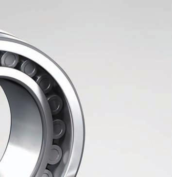


94 SPHERICAL ROLLER BEARINGS
95 Table of Contents Nomenclature... Page D-1 Interchange... Page D-2 Applications... Page D-2 Internal Clearance... Page D Series... Page D Series... Page D Series... Page D Series... Page D Series... Page D Series... Page D Series... Page D Series... Page D Series... Page D-35 Shaker Screen s Nomenclature... Page D-39 Internal Clearance... Page D-39 Interchange... Page D /23300 Series... Page D-41 SPHERICAL ROLLER BEARINGS
96 Spherical Roller s Material Prefix TL: Tough and Long Life HTF: High Tough STF: Super Tough WTF: Water Tough Blank: Standard Materials Bore Size (multiply last two numbers by 5 to get bore in mm) 20: 100 mm 48: 240 mm 32: 160 mm 96: 480 mm 500 millimeters and larger written as: /500: 500 mm /710: 710 mm /630: 630 mm /1000: 1000 mm Bore Type Blank: Cylindrical Bore K: 1:12 Tapered Bore K30: 1:30 Tapered Bore Lubrication Features E3: Holes Only, Outer E4: Groove & Holes, Outer E7: Groove & Holes, Outer & Inner E8: Outer Ring with Tapped Holes in both Faces for Lifting Blank: No Relubriction Feature Other Features P52: Outer Ring Accuracy P53: Inner Ring Accuracy P55: Both Ring Accuracy U22: Special Inspection Measure S11: Inner and Outer Ring Heat Stabilized to 200 C VE: Vibrating Equipment W507: S11, E4, W31 W509: S11, E7, W31 TL CAM K G3 E4 C3 P55S11 Basic Type 213xx: Spherical Roller, Extra Heavy 222xx: Spherical Roller, Heavy 223xx: Spherical Roller, Extra Heavy, Wide 230xx: Spherical Roller, Light 231xx: Spherical Roller, Medium 232xx: Spherical Roller, Heavy, Wide 239xx: Spherical Roller, Extra Light 240xx: Spherical Roller, Light, Wide 241xx: Spherical Roller, Medium, Wide Cage Options CAM: One Piece Brass, Guide Ring C,CD: Two Piece Steel, Guide Ring EA: High Capacity Steel H: Two Piece Polyamide M: Two Piece Brass, Integral Guide Flange Material Code G: Carburized, inner and outer ring rolling element G2: Carburized, outer ring only G3: Carburized, inner ring only G5: Carburized, inner and outer rings Blank: Thru Hardened Steel Internal Clearance C2: Tight Blank: Normal C3: Greater than Normal Clearance C4: Greater than C3 Clearance Please refer to the bearing tables for exact part number options. D-1 SPHERICAL ROLLER BEARINGS
97 Interchange Description Interchange NSK SKF TORR/TIMKEN FAG Part Part Suffix Extra Light 239xx* 239xx 239xx 239xx Light 230xx* 230xx 230xx 230xx Light, Wide 240xx* 240xx 240xx 240xx Medium 231xx* 231xx 231xx 231xx Medium, Wide 241xx* 241xx 241xx 241xx Heavy 222xx* 222xx 222xx 222xx Heavy, Wide 232xx* 232xx 232xx 232xx Extra Heavy 213xx* 213xx 213xx 213xx Extra Heavy, Wide 223xx* 223xx 223xx 223xx Brass Cage, One Piece, Guide Ring CAM, AM CA, CACM YM M, MB, MA Brass Cage, Two Piece, Guide Flange M MC BR -- Steel Cage, Two Piece, Guide Ring C,CD CJ, CC CJ, VJ BLANK High Capacity Steel Cage EA Polyamide Cage, Two Piece H -- VCF TVPB Tapered Bore 1:12 K K K K Tapered Bore 1:30 K30 K30 K K30 Carburized Steel, Complete g ECD W40 W209 Carburized Steel, Inner Ring Only g3 ECB W40I W209B Lube Groove & Holes Outer Ring E4 W33 W33 S Lube Groove & Holes Outer Ring, and Inner Ring E7 W513 W33W94 SH40AB Outer Ring, Tapped Holes One Face for Lifting -- W56 W45A -- Outer Ring, Tapped Holes Both Face for Lifting + E4 Feature E Holes Only Outer Ring E3 W20 W20 SY Inner Ring Lube Groove and Holes E5 W26 W94 H40AB No Relube Features BLANK BLANK BLANK -- Plugs Provided for Outer Ring Holes E42 W77 W84 H40 Combination S11, E4 & W31 W507 W507 W33W4W31 -- Combination W33, W31 E4U22 W506 W33W31 -- Combination S11, E7 & W31 W509 W509 W33W94W31 SH40A Outer Ring with Extra Close Running Accuracy P52 C04 C04 T52BN Inner Ring with Extra Close Running Accuracy P53 C02 C02 T52BE Inner and Outer Ring with Extra Close Running Accuracy P55 C08 C08 T52BW Special Inspection Measures W31 W31 W31 -- Inner Ring and Outer Ring Heat Stabilized to 200 C S11 S Tight Clearance C2 C2 C2 C2 Normal Clearance BLANK BLANK BLANK BLANK Greater than Normal Clearance C3 C3 C3 C3 Greater than C3 Clearance C4 C4 C4 C4 The competitive manufacturers are provided for a convenient source of unit substitution. They can be considered interchangeable in most instances, but for special applications, please consult NSK Engineering. NSK assumes no liability with respect to errors or omissions. * Indicates NSK HPS High Performance Standard Applications Provided below are a few common applications for spherical roller bearings. The spherical roller bearing is designed to handle very heavy loads, even under misalignment or shaft deflection conditions. The spherical shape of the outer ring raceway allows the inner ring to tilt slightly relative to the outer ring without significant loss in bearing life. Spherical roller bearings can also handle axial loading in either direction and heavy shock loads. Continuous Casters (Support Roll, Guide Roll, Pinch Roll, Table Roll) Other Metal Mill Equipment Shaker Screens and Other Vibratory Equipment Paper Making Equipment (Calender Rolls, Dryer Rolls, Fourdrinier) Mining Equipment (Drag Lines, Gyratory Crushers, Continuous Miners, Jaw Crushers) Blowers and Fans Rubber and Plastic Forming Equipment (Extruders, Granulators) Pumps and Compressors (Deep Well, Slurry) Gears, Drives and Reducers Construction Equipment Oil Field Equipment (Pump Jacks, Compounders, Derricks, Hoists) Overhead Cranes, Crane Hooks, Hoists Metal Forming Equipment Railroad Generators and Alternators SPHERICAL ROLLER BEARINGS D-2
98 Spherical Roller s Radial Internal Clearances Radial Internal Clearances in Spherical Roller s with Cylindrical Bores Nominal Bore Diameter Radial Internal Clearance d (mm) C2 C0 C3 C4 over incl. low high low high low high low high Units: inch Radial Internal Clearances in Spherical Roller s with Tapered Bores Nominal Bore Diameter d (mm) Radial Internal Clearance C2 C0 C3 C4 over incl. low high low high low high low high Units: inch D-3 SPHERICAL ROLLER BEARINGS
99 Reduction of Radial Clearance for Spherical Roller s with Tapered Bores Units: inch Nominal Bore Diameter (mm) Radial Internal Clearance (Inch) Reduction in Radial Axial Displacement* CN C3 C4 Clearance Taper 1:12 Taper 1:30 over incl min max min max min max min max min max min max *Axial displacement values apply only to solid steel shafts or hollow steel shafts where the bore is equal to or less than one-half of the outside diameter. If the material is other than steel, or if thin walled shafting is used, please consult NSK. 1:12 Taper applies to Series 222, 223, 230, 231, 232, 233 and :30 Taper applies to Series 240, 241 and 242. For Pe less than 0.13Cr, use the lower half of the reduction range. For heavier loads or Pe greater than 0.13Cr, carburized or TL inner rings should be specified and the upper half of the reduction range can be used. Mounting a Using Radial Clearance Reduction Example: The bearing to be mounted is a 22340CAMKE4C3 [200mm bore (40 x 5) with C3 clearance]. 1. Using feeler gauges, the clearance in the bearing measures From the Reduction in Radial Clearance column in the chart, the reduction in clearance is.0031 to Subtract these numbers from the measured clearance. Measured Clearance Reduction Mounted Clearance is installed by one of the recommended methods until the clearance in the bearing is within the mounted clearance range. For best results, mount bearing at the middle of the range. SPHERICAL ROLLER BEARINGS D-4
100 Spherical Roller s: Series Bore Diameter mm, inch Nominal Dimensions Preferred Shoulder Diameters d D B r** da Da max min max min max mm inch mm inch mm inch mm inch mm inch mm inch mm inch mm inch 21304CDE CDE CDE CDE EAE4* EAE4* EAE4* EAE4* EAE4* EAE4* EAE4* EAE4* EAE4* EAE4* EAE4* CAME4* CAME4* CAME4* *Indicates NSK (HPS) High Performance Standard bearing. **Maximum fillet which corner radius of bearing will clear. D-5 SPHERICAL ROLLER BEARINGS
101 TL HTF STF CAM C,CD EA H K G3 E4 CO* C2 C3 P55 S11 VE COMMON OPTIONS Tough & Long Life High Tough Super Tough One Piece Brass Cage Two Piece Steel Cage High Capacity Steel Cage Two Piece Polyamide Cage 1:12 Tapered Bore Inner Ring Carburized Lube Groove/Holes, Outer Ring Normal Internal Clearance Tight Internal Clearance Greater than Normal Internal Clearance High Running Accuracy Both Rings Heat Stabilized to C Vibrating Equipment *Not shown in part number See page D-1 for additional options. Cr Basic Load Ratings Cor Limiting Speeds (RPM) Weight (Approx.) N lbs N lbs Grease Oil kg lbs 21304CDE CDE CDE CDE EAE4* EAE4* EAE4* EAE4* EAE4* EAE4* EAE4* EAE4* EAE4* EAE4* EAE4* CAME4* CAME4* CAME4* C r = Dynamic Radial Load Rating *Indicates NSK (HPS) High Performance Standard bearing. C or = Static Radial Load Rating SPHERICAL ROLLER BEARINGS D-6
102 Spherical Roller s: Series Bore Diameter mm, inch Nominal Dimensions Preferred Shoulder Diameters d D B r** da Da max min max min max mm inch mm inch mm inch mm inch mm inch mm inch mm inch mm inch 22206CE CE EAE4* EAE4* EAE4* CAME EAE4* CAME EAE4* CAME EAE4* CAME EAE4* CAME EAE4* CAME EAE4* CAME EAE4* CAME EAE4* CAME *Indicates NSK (HPS) High Performance Standard bearing. **Maximum fillet which corner radius of bearing will clear. D-7 SPHERICAL ROLLER BEARINGS
103 TL HTF STF CAM C,CD EA H K G3 E4 CO* C2 C3 P55 S11 VE COMMON OPTIONS Tough & Long Life High Tough Super Tough One Piece Brass Cage Two Piece Steel Cage High Capacity Steel Cage Two Piece Polyamide Cage 1:12 Tapered Bore Inner Ring Carburized Lube Groove/Holes, Outer Ring Normal Internal Clearance Tight Internal Clearance Greater than Normal Internal Clearance High Running Accuracy Both Rings Heat Stabilized to C Vibrating Equipment *Not shown in part number See page D-1 for additional options. Cr Basic Load Ratings Cor Limiting Speeds (RPM) Weight (Approx.) N lbs N lbs Grease Oil kg lbs 22206CE CE EAE4* EAE4* EAE4* CAME EAE4* CAME EAE4* CAME EAE4* CAME EAE4* CAME EAE4* CAME EAE4* CAME EAE4* CAME EAE4* CAME C r = Dynamic Radial Load Rating *Indicates NSK (HPS) High Performance Standard bearing. C or = Static Radial Load Rating SPHERICAL ROLLER BEARINGS D-8
104 Spherical Roller s: Series (cont.) Bore Diameter mm, inch Nominal Dimensions Preferred Shoulder Diameters d D B r** da Da max min max min max mm inch mm inch mm inch mm inch mm inch mm inch mm inch mm inch 22219EAE4* CAME EAE4* CAME EAE4* CAME EAE4* CAME EAE4* CAME CDE CAME4* CDE CAME4* CDE CAME4* CDE CAME4* CDE CAME4* CAME4* CAME4* CAME4* CAME4* CAME4* CAME4* CAME4* CAME4* *Indicates NSK (HPS) High Performance Standard bearing. **Maximum fillet which corner radius of bearing will clear. D-9 SPHERICAL ROLLER BEARINGS
105 TL HTF STF CAM C,CD EA H K G3 E4 CO* C2 C3 P55 S11 VE COMMON OPTIONS Tough & Long Life High Tough Super Tough One Piece Brass Cage Two Piece Steel Cage High Capacity Steel Cage Two Piece Polyamide Cage 1:12 Tapered Bore Inner Ring Carburized Lube Groove/Holes, Outer Ring Normal Internal Clearance Tight Internal Clearance Greater than Normal Internal Clearance High Running Accuracy Both Rings Heat Stabilized to C Vibrating Equipment *Not shown in part number See page D-1 for additional options. Cr Basic Load Ratings Cor Limiting Speeds (RPM) Weight (Approx.) N lbs N lbs Grease Oil kg lbs 22219EAE4* CAME EAE4* CAME EAE4* CAME EAE4* CAME EAE4* CAME CDE CAME4* CDE CAME4* CDE CAME4* CDE CAME4* CDE CAME4* CAME4* CAME4* CAME4* CAME4* CAME4* CAME4* CAME4* CAME4* C r = Dynamic Radial Load Rating *Indicates NSK (HPS) High Performance Standard bearing. C or = Static Radial Load Rating SPHERICAL ROLLER BEARINGS D-10
106 Spherical Roller s: Series Bore Diameter mm, inch Nominal Dimensions Preferred Shoulder Diameters d D B r** da Da max min max min max mm inch mm inch mm inch mm inch mm inch mm inch mm inch mm inch 22308EAE4* CAME EAE4* CAME EAE4* CAME EAE4* CAME EAE4* CAME EAE4* CAME EAE4* CAME EAE4* CAME EAE4* CAME EAE4* CAME EAE4* CAME EAE4* CAME *Indicates NSK (HPS) High Performance Standard bearing. **Maximum fillet which corner radius of bearing will clear. D-11 SPHERICAL ROLLER BEARINGS
107 TL HTF STF CAM C,CD EA H K G3 E4 CO* C2 C3 P55 S11 VE COMMON OPTIONS Tough & Long Life High Tough Super Tough One Piece Brass Cage Two Piece Steel Cage High Capacity Steel Cage Two Piece Polyamide Cage 1:12 Tapered Bore Inner Ring Carburized Lube Groove/Holes, Outer Ring Normal Internal Clearance Tight Internal Clearance Greater than Normal Internal Clearance High Running Accuracy Both Rings Heat Stabilized to C Vibrating Equipment *Not shown in part number See page D-1 for additional options. Cr Basic Load Ratings Cor Limiting Speeds (RPM) Weight (Approx.) N lbs N lbs Grease Oil kg lbs 22308EAE4* CAME EAE4* CAME EAE4* CAME EAE4* CAME EAE4* CAME EAE4* CAME EAE4* CAME EAE4* CAME EAE4* CAME EAE4* CAME EAE4* CAME EAE4* CAME C r = Dynamic Radial Load Rating *Indicates NSK (HPS) High Performance Standard bearing. C or = Static Radial Load Rating SPHERICAL ROLLER BEARINGS D-12
108 Spherical Roller s: Series (cont.) Bore Diameter mm, inch Nominal Dimensions Preferred Shoulder Diameters d D B r** da Da max min max min max mm inch mm inch mm inch mm inch mm inch mm inch mm inch mm inch 22320EAE4* CAME4* EAE4* CAME4* EAE4* CAME4* CE CAME4* CE CAME4* CAME4* CAME4* CAME4* CAME4* CAME4* CAME CAME CAME CAME CAME CAME CAME *Indicates NSK (HPS) High Performance Standard bearing. **Maximum fillet which corner radius of bearing will clear. D-13 SPHERICAL ROLLER BEARINGS
109 TL HTF STF CAM C,CD EA H K G3 E4 CO* C2 C3 P55 S11 VE COMMON OPTIONS Tough & Long Life High Tough Super Tough One Piece Brass Cage Two Piece Steel Cage High Capacity Steel Cage Two Piece Polyamide Cage 1:12 Tapered Bore Inner Ring Carburized Lube Groove/Holes, Outer Ring Normal Internal Clearance Tight Internal Clearance Greater than Normal Internal Clearance High Running Accuracy Both Rings Heat Stabilized to C Vibrating Equipment *Not shown in part number See page D-1 for additional options. Cr Basic Load Ratings Cor Limiting Speeds (RPM) Weight (Approx.) N lbs N lbs Grease Oil kg lbs 22320EAE4* CAME4* EAE4* CAME4* EAE4* CAME4* CE CAME4* CE CAME4* CAME4* CAME4* CAME4* CAME4* CAME4* CAME4* CAME4* CAME4* CAME4* CAME4* CAME CAME C r = Dynamic Radial Load Rating C or = Static Radial Load Rating *Indicates NSK (HPS) High Performance Standard bearing. SPHERICAL ROLLER BEARINGS D-14
110 Spherical Roller s: Series Bore Diameter mm, inch Nominal Dimensions Preferred Shoulder Diameters d D B r** da Da mm inch mm inch mm inch max min max min max mm inch mm inch mm inch mm inch mm inch 23020CDE CDE CAME CDE CAME4* CDE CAME4* CDE CAME4* CDE CAME4* CDE CAME4* CDE CAME4* CDE CAME4* CAME4* CAME4* CAME4* CAME4* CAME4* CAME4* CAME4* CAME4* CAME4* CAME4* CAME4* CAME4* CAME CAME CAME CAME *Indicates NSK (HPS) High Performance Standard bearing. **Maximum fillet which corner radius of bearing will clear. D-15 SPHERICAL ROLLER BEARINGS
111 TL HTF STF CAM C,CD EA H K G3 E4 CO* C2 C3 P55 S11 VE COMMON OPTIONS Tough & Long Life High Tough Super Tough One Piece Brass Cage Two Piece Steel Cage High Capacity Steel Cage Two Piece Polyamide Cage 1:12 Tapered Bore Inner Ring Carburized Lube Groove/Holes, Outer Ring Normal Internal Clearance Tight Internal Clearance Greater than Normal Internal Clearance High Running Accuracy Both Rings Heat Stabilized to C Vibrating Equipment *Not shown in part number See page D-1 for additional options. Cr Basic Load Ratings Cor Limiting Speeds (RPM) Weight (Approx.) N lbs N lbs Grease Oil kg lbs 23020CDE CDE CAME CDE CAME4* CDE CAME4* CDE CAME4* CDE CAME4* CDE CAME4* CDE CAME4* CDE CAME4* CAME4* CAME4* CAME4* CAME4* CAME4* CAME4* CAME4* CAME4* CAME4* CAME4* CAME4* CAME4* CAME CAME CAME CAME C r = Dynamic Radial Load Rating *Indicates NSK (HPS) High Performance Standard bearing. C or = Static Radial Load Rating SPHERICAL ROLLER BEARINGS D-16
112 Spherical Roller s: Series (cont.) Bore Diameter mm, inch Nominal Dimensions Preferred Shoulder Diameters *Maximum fillet which corner radius of bearing will clear. d D B r* da Da mm inch mm inch mm inch max min max min max mm inch mm inch mm inch mm inch mm inch 230/500CAME /530CAME /560CAME /600CAME /630CAME /670CAME /710CAME /750CAME /800CAME /850CAME /900CAME /950CAME /1000CAME /1060CAME /1120CAME /1250CAME D-17 SPHERICAL ROLLER BEARINGS
113 TL HTF STF CAM C,CD EA H K G3 E4 CO* C2 C3 P55 S11 VE COMMON OPTIONS Tough & Long Life High Tough Super Tough One Piece Brass Cage Two Piece Steel Cage High Capacity Steel Cage Two Piece Polyamide Cage 1:12 Tapered Bore Inner Ring Carburized Lube Groove/Holes, Outer Ring Normal Internal Clearance Tight Internal Clearance Greater than Normal Internal Clearance High Running Accuracy Both Rings Heat Stabilized to C Vibrating Equipment *Not shown in part number See page D-1 for additional options. Cr Basic Load Ratings Cor Limiting Speeds (RPM) Weight (Approx.) N lbs N lbs Grease Oil kg lbs 230/500CAME /530CAME /560CAME /600CAME /630CAME /670CAME /710CAME /750CAME /800CAME /850CAME /900CAME /950CAME /1000CAME /1060CAME /1120CAME /1250CAME C r = Dynamic Radial Load Rating C or = Static Radial Load Rating SPHERICAL ROLLER BEARINGS D-18
114 Spherical Roller s: Series Bore Diameter mm, inch Nominal Dimensions Preferred Shoulder Diameters d D B r** da Da mm inch mm inch mm inch max min max min max mm inch mm inch mm inch mm inch mm inch 23120CE CAME CE CAME4* CE CAME4* CE CAME4* CE CAME4* CE CAME4* CE CAME4* CE CAME4* CE CAME4* CE CAME4* CE CAME4* CE CAME4* CE CAME4* TLI CA CAME4* CAME4* CAME4* CAME4* CAME4* CAME4* CAME *Indicates NSK (HPS) High Performance Standard bearing. **Maximum fillet which corner radius of bearing will clear. D-19 SPHERICAL ROLLER BEARINGS
115 TL HTF STF CAM C,CD EA H K G3 E4 CO* C2 C3 P55 S11 VE COMMON OPTIONS Tough & Long Life High Tough Super Tough One Piece Brass Cage Two Piece Steel Cage High Capacity Steel Cage Two Piece Polyamide Cage 1:12 Tapered Bore Inner Ring Carburized Lube Groove/Holes, Outer Ring Normal Internal Clearance Tight Internal Clearance Greater than Normal Internal Clearance High Running Accuracy Both Rings Heat Stabilized to C Vibrating Equipment *Not shown in part number See page D-1 for additional options. Cr Basic Load Ratings Cor Limiting Speeds (RPM) Weight (Approx.) N lbs N lbs Grease Oil kg lbs 23120CE CAME CE CAME4* CE CAME4* CE CAME4* CE CAME4* CE CAME4* CE CAME4* CE CAME4* CE CAME4* CE CAME4* CE CAME4* CE CAME4* CE CAME4* TLI CA CAME4* CAME4* CAME4* CAME4* CAME4* CAME4* CAME C r = Dynamic Radial Load Rating C or = Static Radial Load Rating *Indicates NSK (HPS) High Performance Standard bearing. SPHERICAL ROLLER BEARINGS D-20
116 Spherical Roller s: Series (cont.) Bore Diameter mm, inch Nominal Dimensions Preferred Shoulder Diameters *Maximum fillet which corner radius of bearing will clear. d D B r* da Da mm inch mm inch mm inch max min max min max mm inch mm inch mm inch mm inch mm inch 23180CAME CAME CAME CAME CAME /500CAME /530CAME /560CAME /600CAME /630CAME /670CAME /710CAME /750CAME /800CAME /850CAME /900CAME D-21 SPHERICAL ROLLER BEARINGS
117 TL HTF STF CAM C,CD EA H K G3 E4 CO* C2 C3 P55 S11 VE COMMON OPTIONS Tough & Long Life High Tough Super Tough One Piece Brass Cage Two Piece Steel Cage High Capacity Steel Cage Two Piece Polyamide Cage 1:12 Tapered Bore Inner Ring Carburized Lube Groove/Holes, Outer Ring Normal Internal Clearance Tight Internal Clearance Greater than Normal Internal Clearance High Running Accuracy Both Rings Heat Stabilized to C Vibrating Equipment *Not shown in part number See page D-1 for additional options. Cr Basic Load Ratings Cor Limiting Speeds (RPM) Weight (Approx.) N lbs N lbs Grease Oil kg lbs 23180CAME CAME CAME CAME CAME /500CAME /530CAME /560CAME /600CAME /630CAME /670CAME /710CAME /750CAME /800CAME /850CAME /900CAME C r = Dynamic Radial Load Rating C or = Static Radial Load Rating SPHERICAL ROLLER BEARINGS D-22
118 Spherical Roller s: Series Bore Diameter mm, inch Nominal Dimensions Preferred Shoulder Diameters d D B r** da Da mm inch mm inch mm inch max min max min max mm inch mm inch mm inch mm inch mm inch 23214CAME CE CAME CAME CE CAME4* CE CAME4* CE CAME4* CE CAME4* CE CAME4* CE CAME4* CE CAME4* CE CAME4* CE CAME4* CE CAME4* CE CAME4* CE CAME4* CAME4* CAME4* CAME4* *Indicates NSK (HPS) High Performance Standard bearing. **Maximum fillet which corner radius of bearing will clear. D-23 SPHERICAL ROLLER BEARINGS
119 TL HTF STF CAM C,CD EA H K G3 E4 CO* C2 C3 P55 S11 VE COMMON OPTIONS Tough & Long Life High Tough Super Tough One Piece Brass Cage Two Piece Steel Cage High Capacity Steel Cage Two Piece Polyamide Cage 1:12 Tapered Bore Inner Ring Carburized Lube Groove/Holes, Outer Ring Normal Internal Clearance Tight Internal Clearance Greater than Normal Internal Clearance High Running Accuracy Both Rings Heat Stabilized to C Vibrating Equipment *Not shown in part number See page D-1 for additional options. Cr Basic Load Ratings Cor Limiting Speeds (RPM) Weight (Approx.) N lbs N lbs Grease Oil kg lbs 23214CAME CE CAME CAME CE CAME4* CE CAME4* CE CAME4* CE CAME4* CE CAME4* CE CAME4* CE CAME4* CE CAME4* CE CAME4* CE CAME4* CE CAME4* CE CAME4* CAME4* CAME4* CAME4* C r = Dynamic Radial Load Rating *Indicates NSK (HPS) High Performance Standard bearing. C or = Static Radial Load Rating SPHERICAL ROLLER BEARINGS D-24
120 Spherical Roller s: Series (cont.) Bore Diameter mm, inch Nominal Dimensions Preferred Shoulder Diameters *Maximum fillet which corner radius of bearing will clear. d D B r* da Da mm inch mm inch mm inch max min max min max mm inch mm inch mm inch mm inch mm inch 23260CAME4* CAME4* CAME CAME CAME CAME CAME CAME CAME CAME /500CAME /530CAME /560CAME /600CAME /630CAME /670CAME /710CAME /750CAME /800CAME /850CAME /950CAME D-25 SPHERICAL ROLLER BEARINGS
121 TL HTF STF CAM C,CD EA H K G3 E4 CO* C2 C3 P55 S11 VE COMMON OPTIONS Tough & Long Life High Tough Super Tough One Piece Brass Cage Two Piece Steel Cage High Capacity Steel Cage Two Piece Polyamide Cage 1:12 Tapered Bore Inner Ring Carburized Lube Groove/Holes, Outer Ring Normal Internal Clearance Tight Internal Clearance Greater than Normal Internal Clearance High Running Accuracy Both Rings Heat Stabilized to C Vibrating Equipment *Not shown in part number See page D-1 for additional options. Cr Basic Load Ratings Cor Limiting Speeds (RPM) Weight (Approx.) N lbs N lbs Grease Oil kg lbs 23260CAME4* CAME4* CAME CAME CAME CAME CAME CAME CAME CAME /500CAME /530CAME /560CAME /600CAME /630CAME /670CAME /710CAME /750CAME /800CAME /850CAME /950CAME C r = Dynamic Radial Load Rating *Indicates NSK (HPS) High Performance Standard bearing. C or = Static Radial Load Rating SPHERICAL ROLLER BEARINGS D-26
122 Spherical Roller s: Series Bore Diameter mm, inch Nominal Dimensions Preferred Shoulder Diameters d D B r** da Da mm inch mm inch mm inch max min max min max mm inch mm inch mm inch mm inch mm inch 23926CAME CAME4* CAME4* CAME4* CAME4* CAME4* CAME4* CAME4* CAME4* CAME4* CAME4* CAME4* CAME4* CAME4* CAME4* CAME4* CAME4* CAME CAME CAME /500CAME /530CAME /560CAME /600CAME /630CAME /670CAME /710CAME /750CAME *Indicates NSK (HPS) High Performance Standard bearing. **Maximum fillet which corner radius of bearing will clear. D-27 SPHERICAL ROLLER BEARINGS
123 TL HTF STF CAM C,CD EA H K G3 E4 CO* C2 C3 P55 S11 VE COMMON OPTIONS Tough & Long Life High Tough Super Tough One Piece Brass Cage Two Piece Steel Cage High Capacity Steel Cage Two Piece Polyamide Cage 1:12 Tapered Bore Inner Ring Carburized Lube Groove/Holes, Outer Ring Normal Internal Clearance Tight Internal Clearance Greater than Normal Internal Clearance High Running Accuracy Both Rings Heat Stabilized to C Vibrating Equipment *Not shown in part number See page D-1 for additional options. Cr Basic Load Ratings Cor Limiting Speeds (RPM) Weight (Approx.) N lbs N lbs Grease Oil kg lbs 23926CAME CAME4* CAME4* CAME4* CAME4* CAME4* CAME4* CAME4* CAME4* CAME4* CAME4* CAME4* CAME4* CAME4* CAME4* CAME4* CAME4* CAME CAME CAME /500CAME /530CAME /560CAME /600CAME /630CAME /670CAME /710CAME /750CAME C r = Dynamic Radial Load Rating *Indicates NSK (HPS) High Performance Standard bearing. C or = Static Radial Load Rating SPHERICAL ROLLER BEARINGS D-28
124 Spherical Roller s: Series (cont.) Bore Diameter mm, inch Nominal Dimensions Preferred Shoulder Diameters *Maximum fillet which corner radius of bearing will clear. d D B r* da Da mm inch mm inch mm inch max min max min max mm inch mm inch mm inch mm inch mm inch 239/800CAME /850CAME /900CAME /950CAME /1000CAME /1060CAME /1120CAME /1180CAME /1250CAME /1400CAME D-29 SPHERICAL ROLLER BEARINGS
125 TL HTF STF CAM C,CD EA H K G3 E4 CO* C2 C3 P55 S11 VE COMMON OPTIONS Tough & Long Life High Tough Super Tough One Piece Brass Cage Two Piece Steel Cage High Capacity Steel Cage Two Piece Polyamide Cage 1:12 Tapered Bore Inner Ring Carburized Lube Groove/Holes, Outer Ring Normal Internal Clearance Tight Internal Clearance Greater than Normal Internal Clearance High Running Accuracy Both Rings Heat Stabilized to C Vibrating Equipment *Not shown in part number See page D-1 for additional options. Cr Basic Load Ratings Cor Limiting Speeds (RPM) Weight (Approx.) N lbs N lbs Grease Oil kg lbs 239/800CAME /850CAME /900CAME /950CAME /1000CAME /1060CAME /1120CAME /1180CAME /1250CAME /1400CAME C r = Dynamic Radial Load Rating C or = Static Radial Load Rating SPHERICAL ROLLER BEARINGS D-30
126 Spherical Roller s: Series Bore Diameter mm, inch Nominal Dimensions Preferred Shoulder Diameters d D B r** da Da mm inch mm inch mm inch max min max min max mm inch mm inch mm inch mm inch mm inch 24020CE CE CE CAME4* CE CAME4* CE CAME4* CE CAME4* CE CAME4* CE CAME4* CE CAME4* CE CAME4* CE CAME4* CE CAME4* CE CAME4* CAME4* CAME4* CAME4* CAME4* CAME4* CAME4* CAME4* CAME4* CAME *Indicates NSK (HPS) High Performance Standard bearing. **Maximum fillet which corner radius of bearing will clear. D-31 SPHERICAL ROLLER BEARINGS
127 TL HTF STF CAM C,CD EA H K30 G3 E4 CO* C2 C3 P55 S11 COMMON OPTIONS Tough & Long Life High Tough Super Tough One Piece Brass Cage Two Piece Steel Cage High Capacity Steel Cage Two Piece Polyamide Cage 1:30 Tapered Bore Inner Ring Carburized Lube Groove/Holes, Outer Ring Normal Internal Clearance Tight Internal Clearance Greater than Normal Internal Clearance High Running Accuracy Both Rings Heat Stabilized to C VE Vibrating Equipment *Not shown in part number See page D-1 for additional options. Cr Basic Load Ratings Cor Limiting Speeds (RPM) Weight (Approx.) N lbs N lbs Grease Oil kg lbs 24020CE CE CE CAME4* CE CAME4* CE CAME4* CE CAME4* CE CAME4* CE CAME4* CE CAME4* CE CAME4* CE CAME4* CE CAME4* CE CAME4* CAME4* CAME4* CAME4* CAME4* CAME4* CAME4* CAME4* CAME4* CAME C r = Dynamic Radial Load Rating *Indicates NSK (HPS) High Performance Standard bearing. C or = Static Radial Load Rating SPHERICAL ROLLER BEARINGS D-32
128 Spherical Roller s: Series (cont.) Bore Diameter mm, inch Nominal Dimensions Preferred Shoulder Diameters *Maximum fillet which corner radius of bearing will clear. d D B r* da Da mm inch mm inch mm inch max min max min max mm inch mm inch mm inch mm inch mm inch 24088CAME CAME CAME /500CAME /530CAME /560CAME /600CAME /630CAME /670CAME /710CAME /800CAME /850CAME /950CAME /1000CAME /1120CAME /1250CAME /1320CAME /1400CAME D-33 SPHERICAL ROLLER BEARINGS
129 TL HTF STF CAM C,CD EA H K30 G3 E4 CO* C2 C3 P55 S11 VE COMMON OPTIONS Tough & Long Life High Tough Super Tough One Piece Brass Cage Two Piece Steel Cage High Capacity Steel Cage Two Piece Polyamide Cage 1:30 Tapered Bore Inner Ring Carburized Lube Groove/Holes, Outer Ring Normal Internal Clearance Tight Internal Clearance Greater than Normal Internal Clearance High Running Accuracy Both Rings Heat Stabilized to C Vibrating Equipment *Not shown in part number See page D-1 for additional options. Cr Basic Load Ratings Cor Limiting Speeds (RPM) Weight (Approx.) N lbs N lbs Grease Oil kg lbs 24088CAME CAME CAME /500CAME /530CAME /560CAME /600CAME /630CAME /670CAME /710CAME /800CAME /850CAME /950CAME /1000CAME /1120CAME /1250CAME /1320CAME /1400CAME C r = Dynamic Radial Load Rating C or = Static Radial Load Rating SPHERICAL ROLLER BEARINGS D-34
130 Spherical Roller s: Series Bore Diameter mm, inch Nominal Dimensions Preferred Shoulder Diameters d D B r** da Da mm inch mm inch mm inch max min max min max mm inch mm inch mm inch mm inch mm inch 24120CAME CE CAME4* CE CAME4* CE CAME4* CE CAME4* CE CAME4* CE CAME4* CE CAME4* CE CAME4* CE CAME4* CE CAME4* CE CAME4* CE CAME4* CE CAME4* CXE CAME4* CXE CAME4* CXE CAME4* *Indicates NSK (HPS) High Performance Standard bearing. **Maximum fillet which corner radius of bearing will clear. D-35 SPHERICAL ROLLER BEARINGS
131 TL HTF STF CAM C,CD EA H K30 G3 E4 CO* C2 C3 P55 S11 VE COMMON OPTIONS Tough & Long Life High Tough Super Tough One Piece Brass Cage Two Piece Steel Cage High Capacity Steel Cage Two Piece Polyamide Cage 1:30 Tapered Bore Inner Ring Carburized Lube Groove/Holes, Outer Ring Normal Internal Clearance Tight Internal Clearance Greater than Normal Internal Clearance High Running Accuracy Both Rings Heat Stabilized to C Vibrating Equipment *Not shown in part number See page D-1 for additional options. Cr Basic Load Ratings Cor Limiting Speeds (RPM) Weight (Approx.) N lbs N lbs Grease Oil kg lbs 24120CAME CE CAME4* CE CAME4* CE CAME4* CE CAME4* CE CAME4* CE CAME4* CE CAME4* CE CAME4* CE CAME4* CE CAME4* CE CAME4* CE CAME4* CE CAME4* CXE CAME4* CXE CAME4* CXE CAME4* C r = Dynamic Radial Load Rating *Indicates NSK (HPS) High Performance Standard bearing. C or = Static Radial Load Rating SPHERICAL ROLLER BEARINGS D-36

132 Spherical Roller s: Series (cont.) Bore Diameter mm, inch Nominal Dimensions Preferred Shoulder Diameters *Maximum fillet which corner radius of bearing will clear. d D B r* da Da mm inch mm inch mm inch max min max min max mm inch mm inch mm inch mm inch mm inch 24168CXE CAME4* CAME4* CXE CAME CAME CAME CAME CAME CAME /500CAME /560CAME /600CAME /630CAME /670CAME D-37 SPHERICAL ROLLER BEARINGS
133 TL HTF STF CAM C,CD EA H K30 G3 E4 CO* C2 C3 P55 S11 VE COMMON OPTIONS Tough & Long Life High Tough Super Tough One Piece Brass Cage Two Piece Steel Cage High Capacity Steel Cage Two Piece Polyamide Cage 1:30 Tapered Bore Inner Ring Carburized Lube Groove/Holes, Outer Ring Normal Internal Clearance Tight Internal Clearance Greater than Normal Internal Clearance High Running Accuracy Both Rings Heat Stabilized to C Vibrating Equipment *Not shown in part number See page D-1 for additional options. Cr Basic Load Ratings Cor Limiting Speeds (RPM) Weight (Approx.) N lbs N lbs Grease Oil kg lbs 24168CXE CAME4* CAME4* CXE CAME CAME CAME CAME CAME CAME /500CAME /560CAME /600CAME /630CAME /670CAME C r = Dynamic Radial Load Rating *Indicates NSK (HPS) High Performance Standard bearing. C or = Static Radial Load Rating SPHERICAL ROLLER BEARINGS D-38

134 Shaker Screen s Vibrating Equipment Specification Spherical Bore Diameter Oil Groove & Holes in Outer Ring Higher Precision Bore & OD Tolerances Special Radial Internal Clearance Range Unique Combination of Geometry & Finishes Optimize Performance VE: Vibrating Screen SBVS/SAVS: Special Dimension Vibrating Screen CAM E4 C4 VE TF Series Cage Option CAM: Machined Brass Cage Internal Clearance Specification Material TF: Tough Steel Please refer to the bearing tables for exact part number options. Radial Internal Clearance (inches) Unmounted Mounted Bore (mm) C3 C4 C3 C4 min max min max min max min max D-39 SPHERICAL ROLLER BEARINGS
135 Interchange NSK TORR/TIMKEN SKF FAG* Part Interchange 22308CAME4C4VE 22308YMW33W800C E/VA EAS.MA.T41A 22309CAME4C4VE 22309YMW33W800C E/VA EAS.MA.T41A 22310CAME4C4VE 22310YMW33W800C E/VA EAS.MA.T41A 22311CAME4C4VE 22311YMW33W800C E/VA EAS.MA.T41A 22312CAME4C4VE 22312YMW33W800C E/VA EAS.MA.T41A 22313CAME4C4VE 22313YMW33W800C E/VA EAS.MA.T41A 22314CAME4C4VE 22314YMW33W800C E/VA EAS.MA.T41A 22315CAME4C4VE 22315YMW33W800C EJA/VA EAS.MA.T41A 22316CAME4C4VE 22316YMW33W800C EJA/VA EAS.MA.T41A 22317CAME4C4VE 22317YMW33W800C EJA/VA EAS.MA.T41A 22318CAME4C4VE 22318YMW33W800C EJA/VA EAS.MA.T41A 22319CAME4C4VE 22319YMW33W800C EJA/VA EAS.MA.T41A 22319CAMC4VE 22319YMW800C CAME4C4VE 22320YMW33W800C EJA/VA EAS.MA.T41A 22322CAME4C4VE 22322YMW33W800C EJA/VA EAS.MA.T41A 22322CAME4CG195SBVS 22322YMW47W22C EJA/VA EAS.MA.T41B 22324CAME4C4VE 22324YMW33W800C CCJA/W33VA EAS.MA.T41A 22326CAME4C4VE 22326YMW33W800C CCJA/W33VA EAS.MA.T41A 22328CAME4C4VE 22328YMW33W800C CCJA/W33VA EAS.MA.T41A 22330CAME4C4VE 22330YMW33W800C CCJA/W33VA EAS.MA.T41A 22332CAME4C4VE 22332YMW33W800C CCJA/W33VA A.MA.T41A 22334CAME4C4VE 22334YMBW33W800C CCJA/W33VA A.MA.T41A 22336CAME4C4VE 22336YMBW33W800C CCJA/W33VA A.MA.T41A 22338CAME4C4VE 22338YMBW33W800C CCJA/W33VA A.MA.T41A 22340CAME4C4VE YMBW33W45AW800C CCJA/W33VA A.MA.T41A 23322CAME4C4VE 23322W33W800C EJA/VA AS.MA.T41A 23322CAMC4VE YM W800 C C3.F CAME4C4VE 23324YMW33W800C CCJA/W33VA AS.MA.T41A 23324CAMC4VE 23324YMW800C CAME4C4VE 23326YMW33W800C CCJA/W33VA AS.MA.T41A 23328CAME4C4VE 23328YMW33W800C CCJA/W33VA AS.MA.T41A 23328CAMC4VE 23328YMW800C CAME4C4VE 23330YMBW33W800C CCJA/W33VA A.MA.T41A 23332CAME4C4VE 23332YMBW33W800C CCJA/W33VA A.MA.T41A 23332CAMC4VE 23332YMBW800C CAME4C4SBVS 23332YMBW33W47W22C CCJA/W33VA EAS.MA.T41B 23338CAME4C4VE 23338YMBW33W22BRC CCJA/W33VA ASMAC4F CAME4C4VE CCJA/W33VA405 - Nomenclature Interchange Shaker Screen Specification VE W800 VA405 T41A Durotect Bore Coating T41D Standard Series or Wide Series Allis Chalmers Oversized Bore Sa, Sb W47 VA414 T41B PTFE Coating On Bore - - VA406 - Undersized Cedar Rapids Sa, Sb W810-5XXX.F80 * NSK bearings with CAME4C4VE suffix may also be used in place of bearings with FAG suffix T41A, T41B, T41. The competitive manufacturers are provided for a convenient source of unit substitution. They can be considered interchangeable in most instances, but for special applications, please consult NSK Engineering. NSK assumes no liability with respect to errors or omissions. SPHERICAL ROLLER BEARINGS D-40
136 Shaker Screen s: 22300/23300 Series 223 Series Dimensions CAM Design Bore O.D. Width Capacity C r Limiting Speeds (RPM) mm inch mm inch mm inch N lbs Grease Oil Series D-41 SPHERICAL ROLLER BEARINGS
137 Shaker Screen s: 22300/23300 Series Fitting Recommendations Shaft Diameter 223 Series Housing Bore Diameter max min fit min max fit mm inch mm inch mm inch mm inch mm inch mm inch L L L L T T T T L L L L T T T T L L L L T T T T L L L L T T T T L L L L T T T T L L L L T T T T L L L L T T T T L L L L T T T T L L L L T T T T L L L L T T T T L L L L T T T T L L L L T T T T L L L L T T T T L L L L T T T T L L L L T T T T L L L L T T T T L L L L T T T T L L L L T T T T L L L L T T T T L L L L T T T T L L L L T T T T L L L L T T T T 233 Series L L L L T T T T L L L L T T T T L L L L T T T T L L L L T T T T L L L L T T T T L L L L T T T T L L L L T T T T L L L L T T T T L L L L T T T T SPHERICAL ROLLER BEARINGS D-42


138 TAPERED ROLLER BEARINGS
139 Table of Contents Metric Tapered Roller s Nomenclature... Page E-1 Interchange... Page E-2 Applications... Page E Metric Series... Page E Metric Series... Page E Metric Series... Page E Metric Series... Page E Metric Series... Page E Metric Series... Page E Metric Series... Page E Metric Series... Page E Metric Series... Page E Metric Series... Page E C Metric Series... Page E C Metric Series... Page E C Metric Series... Page E-27 Inch Tapered Roller s Nomenclature... Page E-29 Interchange... Page E-30 Applications... Page E-30 Inch Series... Page E-31 TAPERED ROLLER BEARINGS
140 Metric Tapered Roller s Prefix HR: High Capacity Blank: Normal Capacity Bore Size (04 and up: multiply last two numbers by 5 to get bore in mm) 02: 12 mm 08: 40 mm 03: 17 mm 10: 50 mm 04: 20 mm 20: 100 mm Special bore sizes are as follows: /22: 22 mm /32: 32 mm /28: 28 mm Interchangeability J: Cup Angle and Raceway Diameter Conform to ISO 355 X: Dimension Series and the Major Dimensions Conform to ISO 355 STF HR C J Material Prefix HTF: High Tough STF: Super Tough WTF: Water Tough Blank: Standard Materials Series Contact Angle Blank: Standard Angle = 15 to 17 C: Medium Angle = 17 to 24 D: Steep Angle= 24 and more Please refer to the bearing tables for exact part number options E-1 TAPERED ROLLER BEARINGS
141 Interchange Description Interchange NSK SKF Timken FAG Part Suffix High Capacity Design HR Light HR302xx 302xx 302xx 302xx Medium HR303xx 303xx 303xx 303xx Medium, Steep Angle HR313xx 313xx 313xx 313xx Extra Light, Wide HR329xx 329xx 329xx 329xx Very Light, Wide HR320xx 320xx 320xx 320xx Light, Wide HR322xx 322xx 322xx 322xx Medium, Wide HR323xx 323xx 323xx 323xx Very Light, Extra Wide HR330xx 330xx 330xx 330xx Light, Extra Wide HR331xx 331xx 331xx 331xx Medium, Extra Wide HR332xx 332xx 332xx 332xx Medium Contact Angle C B B B Steep Contact Angle D Boundary Dimensions Conform to ISO 355 X X X X Conforms to ISO 355 J A *HR313xx is directly equal to HR303xxD. The competitive manufacturers are provided for a convenient source of unit substitution. They can be considered interchangeable in most instances, but for special applications, please contact NSK. NSK assumes no liability with respect to errors or omissions. Applications Shown below are some common applications utilizing a tapered roller bearing design. The design allows for combinations of heavy radial and thrust loads with low to moderate speeds. This section covers only single row tapers although NSK manufactures a full line of two and four row tapers as well. For more details on multiple row tapered roller bearings, please contact an NSK representative. Metric designs function the same as their inch series cousins, the difference lies in the units of measure. NSK metric tapers are standardly supplied with cup and cone together, while inch series bearing are available by the cup, cone, or cup and cone. The applications shown below are for either metric or inch bearings, with the equipment manufacturer choosing the preference of dimensional measurements. Metric tapers are usually found in equipment designed in Europe or Asia. Guide Boxes in Bar and Rod Mills Pumps and Compressors Cranes and Hoists Gears and Drives Stamping Presses Machine Tool Spindles Bow Thrusts on Ships Speed Reducers Transmissions Sheaves Conveyor and Transfer Equipment Construction Equipment Mining Equipment Oil Field Equipment Automotive Front and Rear Axles Plastic Forming Equipment Agriculture Equipment Motorcycle Wheels Pinion Shafts of Differential Gears Drum Shafts Crankshafts Crushers TAPERED ROLLER BEARINGS E-2
142 Tapered Roller s: Metric Series Bore Diameter mm, inch Nominal Dimensions d D T B C Preferred Shoulder Diameters r* (Shaft) r* (Housing) da db Da max max min max max mm inch mm inch mm inch mm inch mm inch mm inch mm inch mm inch mm inch mm inch J J J J J J J J J J J J J J J J J J J J J J J *Maximum fillet which corner radius of bearing will clear. E-3 TAPERED ROLLER BEARINGS
143 Cr Basic Load Ratings N lbs N lbs Cor Limiting Speeds (RPM) Effective Load Center (a) Weight (Approx.) Grease Oil mm inch kg lbs J J J J J J J J J J J J J J J J J J J J J J J C r = Dynamic Radial Load Rating C or = Static Radial Load Rating TAPERED ROLLER BEARINGS E-4
144 Tapered Roller s: Metric Series Bore Diameter mm, inch *Maximum fillet which corner radius of bearing will clear. Nominal Dimensions d D T B C Preferred Shoulder Diameters r* (Shaft) r* (Housing) da db Da max max min max max mm inch mm inch mm inch mm inch mm inch mm inch mm inch mm inch mm inch mm inch HR30302J HR30303J HR30304J HR303/ HR30305J HR303/ HR30306J HR303/ HR30307J HR30308J HR30309J HR30310J HR30311J HR30312J HR30313J HR30314J HR30315J HR30316J HR30317J HR30318J HR30319J HR30320J HR30321J HR30322J HR30324J HR30326J HR30328J HR30330J HR30332J HR30334J E-5 TAPERED ROLLER BEARINGS
145 C r = Dynamic Radial Load Rating Cr Basic Load Ratings N lbs N lbs C or = Static Radial Load Rating Cor Limiting Speeds (RPM) Effective Load Center (a) Weight (Approx.) Grease Oil mm inch kg lbs HR30302J HR30303J HR30304J HR303/ HR30305J HR303/ HR30306J HR303/ HR30307J HR30308J HR30309J HR30310J HR30311J HR30312J HR30313J HR30314J HR30315J HR30316J HR30317J HR30318J HR30319J HR30320J HR30321J HR30322J HR30324J HR30326J HR30328J HR30330J HR30332J HR30334J TAPERED ROLLER BEARINGS E-6
146 Tapered Roller s: Metric Series Bore Diameter mm, inch *Maximum fillet which corner radius of bearing will clear. Nominal Dimensions d D T B C Preferred Shoulder Diameters r* (Shaft) r* (Housing) da db Da max max min max max mm inch mm inch mm inch mm inch mm inch mm inch mm inch mm inch mm inch mm inch HR31305J HR31306J HR31307J HR31308J HR31309J HR31310J HR31311J HR31312J HR31313J HR31314J HR31315J HR31316J HR31317J HR31318J HR31319J HR31320J HR31321J HR31322J HR31324J HR31326J HR31328J HR31330J E-7 TAPERED ROLLER BEARINGS
147 C r = Dynamic Radial Load Rating Cr Basic Load Ratings N lbs N lbs C or = Static Radial Load Rating Cor Limiting Speeds (RPM) Effective Load Center (a) Weight (Approx.) Grease Oil mm inch kg lbs HR31305J HR31306J HR31307J HR31308J HR31309J HR31310J HR31311J HR31312J HR31313J HR31314J HR31315J HR31316J HR31317J HR31318J HR31319J HR31320J HR31321J HR31322J HR31324J HR31326J HR31328J HR31330J TAPERED ROLLER BEARINGS E-8
148 Tapered Roller s: Metric Series Bore Diameter mm, inch *Maximum fillet which corner radius of bearing will clear. Nominal Dimensions d D T B C Preferred Shoulder Diameters r* (Shaft) r* (Housing) da db Da max max min max max mm inch mm inch mm inch mm inch mm inch mm inch mm inch mm inch mm inch mm inch HR32004XJ HR320/22XJ HR32005XJ HR320/28XJ HR32006XJ HR320/32XJ HR32007XJ HR32008XJ HR32009XJ HR32010XJ HR32011XJ HR32012XJ HR32013XJ HR32014XJ HR32015XJ HR32016XJ HR32017XJ HR32018XJ HR32019XJ HR32020XJ HR32021XJ HR32022XJ HR32024XJ HR32026XJ HR32028XJ HR32030XJ HR32032XJ HR32034XJ HR32036XJ HR32038XJ HR32040XJ HR32044XJ HR32048XJ HR32052XJ HR32056XJ HR32060XJ HR32064XJ E-9 TAPERED ROLLER BEARINGS
149 C r = Dynamic Radial Load Rating Cr Basic Load Ratings N lbs N lbs C or = Static Radial Load Rating Cor Limiting Speeds (RPM) Effective Load Center (a) Weight (Approx.) Grease Oil mm inch kg lbs HR32004XJ HR320/22XJ HR32005XJ HR320/28XJ HR32006XJ HR320/32XJ HR32007XJ HR32008XJ HR32009XJ HR32010XJ HR32011XJ HR32012XJ HR32013XJ HR32014XJ HR32015XJ HR32016XJ HR32017XJ HR32018XJ HR32019XJ HR32020XJ HR32021XJ HR32022XJ HR32024XJ HR32026XJ HR32028XJ HR32030XJ HR32032XJ HR32034XJ HR32036XJ HR32038XJ HR32040XJ HR32044XJ HR32048XJ HR32052XJ HR32056XJ HR32060XJ HR32064XJ TAPERED ROLLER BEARINGS E-10
150 Tapered Roller s: Metric Series Bore Diameter mm, inch *Maximum fillet which corner radius of bearing will clear. Nominal Dimensions d D T B C Preferred Shoulder Diameters r* (Shaft) r* (Housing) da db Da max max min max max mm inch mm inch mm inch mm inch mm inch mm inch mm inch mm inch mm inch mm inch HR32203J HR32204J HR322/ HR32205J HR322/ HR32206J HR322/ HR32207J HR32208J HR32209J HR32210J HR32211J HR32212J HR32213J HR32214J HR32215J HR32216J HR32217J HR32218J HR32219J HR32220J HR32221J HR32222J HR32224J HR32226J HR32228J HR32230J HR32232J HR32234J HR32236J HR32238J HR32240J E-11 TAPERED ROLLER BEARINGS
151 Cr Basic Load Ratings N lbs N lbs Cor Limiting Speeds (RPM) Effective Load Center (a) Weight (Approx.) Grease Oil mm inch kg lbs HR32203J HR32204J HR322/ HR32205J HR322/ HR32206J HR322/ HR32207J HR32208J HR32209J HR32210J HR32211J HR32212J HR32213J HR32214J HR32215J HR32216J HR32217J HR32218J HR32219J HR32220J HR32221J HR32222J HR32224J HR32226J HR32228J HR32230J HR32232J HR32234J HR32236J HR32238J HR32240J C r = Dynamic Radial Load Rating C or = Static Radial Load Rating TAPERED ROLLER BEARINGS E-12
152 Tapered Roller s: Metric Series Bore Diameter mm, inch *Maximum fillet which corner radius of bearing will clear. Nominal Dimensions d D T B C Preferred Shoulder Diameters r* (Shaft) r* (Housing) da db Da max max min max max mm inch mm inch mm inch mm inch mm inch mm inch mm inch mm inch mm inch mm inch HR32303J HR32304J HR32305J HR32306J HR32307J HR32308J HR32309J HR32310J HR32311J HR32312J HR32313J HR32314J HR32315J HR32316J HR32317J HR32318J HR32319J HR32320J HR32321J HR32322J HR32324J E-13 TAPERED ROLLER BEARINGS
153 Cr Basic Load Ratings N lbs N lbs Cor Limiting Speeds (RPM) Effective Load Center (a) Weight (Approx.) Grease Oil mm inch kg lbs HR32303J HR32304J HR32305J HR32306J HR32307J HR32308J HR32309J HR32310J HR32311J HR32312J HR32313J HR32314J HR32315J HR32316J HR32317J HR32318J HR32319J HR32320J HR32321J HR32322J HR32324J C r = Dynamic Radial Load Rating C or = Static Radial Load Rating TAPERED ROLLER BEARINGS E-14
154 Tapered Roller s: Metric Series Bore Diameter mm, inch *Maximum fillet which corner radius of bearing will clear. Nominal Dimensions d D T B C Preferred Shoulder Diameters r* (Shaft) r* (Housing) da db Da max max min max max mm inch mm inch mm inch mm inch mm inch mm inch mm inch mm inch mm inch mm inch HR32906J HR32907J HR32908J HR32909J HR32910J HR32911J HR32912J HR32913J HR32914J HR32915J HR32916J HR32917J HR32918J HR32919J HR32920J HR32921J HR32922J HR32924J HR32926J HR32928J HR32930J HR32932J HR32934J HR32936J HR32938J HR32940J HR32944J HR32948J HR32952J HR32956J HR32960J HR32964J HR32968J HR32972J E-15 TAPERED ROLLER BEARINGS
155 C r = Dynamic Radial Load Rating Cr Basic Load Ratings N lbs N lbs C or = Static Radial Load Rating Cor Limiting Speeds (RPM) Effective Load Center (a) Weight (Approx.) Grease Oil mm inch kg lbs HR32906J HR32907J HR32908J HR32909J HR32910J HR32911J HR32912J HR32913J HR32914J HR32915J HR32916J HR32917J HR32918J HR32919J HR32920J HR32921J HR32922J HR32924J HR32926J HR32928J HR32930J HR32932J HR32934J HR32936J HR32938J HR32940J HR32944J HR32948J HR32952J HR32956J HR32960J HR32964J HR32968J HR32972J TAPERED ROLLER BEARINGS E-16
156 Tapered Roller s: Metric Series Bore Diameter mm, inch *Maximum fillet which corner radius of bearing will clear. Nominal Dimensions d D T B C Preferred Shoulder Diameters r* (Shaft) r* (Housing) da db Da max max min max max mm inch mm inch mm inch mm inch mm inch mm inch mm inch mm inch mm inch mm inch HR33005J HR33006J HR33007J HR33008J HR33009J HR33010J HR33011J HR33012J HR33013J HR33014J HR33015J HR33016J HR33017J HR33018J HR33019J HR33020J HR33021J HR33022J HR33024J E-17 TAPERED ROLLER BEARINGS
157 C r = Dynamic Radial Load Rating Cr Basic Load Ratings N lbs N lbs C or = Static Radial Load Rating Cor Limiting Speeds (RPM) Effective Load Center (a) Weight (Approx.) Grease Oil mm inch kg lbs HR33005J HR33006J HR33007J HR33008J HR33009J HR33010J HR33011J HR33012J HR33013J HR33014J HR33015J HR33016J HR33017J HR33018J HR33019J HR33020J HR33021J HR33022J HR33024J TAPERED ROLLER BEARINGS E-18
158 Tapered Roller s: Metric Series Bore Diameter mm, inch *Maximum fillet which corner radius of bearing will clear. Nominal Dimensions d D T B C Preferred Shoulder Diameters r* (Shaft) r* (Housing) da db Da max max min max max mm inch mm inch mm inch mm inch mm inch mm inch mm inch mm inch mm inch mm inch HR33109J HR33110J HR33111J HR33112J HR33113J HR33114J HR33115J HR33116J HR33117J HR33118J HR33120J HR33122J E-19 TAPERED ROLLER BEARINGS
159 Cr Basic Load Ratings N lbs N lbs Cor Limiting Speeds (RPM) Effective Load Center (a) Weight (Approx.) Grease Oil mm inch kg lbs HR33109J HR33110J HR33111J HR33112J HR33113J HR33114J HR33115J HR33116J HR33117J HR33118J HR33120J HR33122J C r = Dynamic Radial Load Rating C or = Static Radial Load Rating TAPERED ROLLER BEARINGS E-20
160 Tapered Roller s: Metric Series Bore Diameter mm, inch *Maximum fillet which corner radius of bearing will clear. Nominal Dimensions d D T B C Preferred Shoulder Diameters r* (Shaft) r* (Housing) da db Da max max min max max mm inch mm inch mm inch mm inch mm inch mm inch mm inch mm inch mm inch mm inch HR33205J HR33206J HR33207J HR33208J HR33209J HR33210J HR33211J HR33212J HR33213J HR33214J HR33215J HR33216J HR33217J HR33220J E-21 TAPERED ROLLER BEARINGS
161 C r = Dynamic Radial Load Rating Cr Basic Load Ratings N lbs N lbs C or = Static Radial Load Rating Cor Limiting Speeds (RPM) Effective Load Center (a) Weight (Approx.) Grease Oil mm inch kg lbs HR33205J HR33206J HR33207J HR33208J HR33209J HR33210J HR33211J HR33212J HR33213J HR33214J HR33215J HR33216J HR33217J HR33220J TAPERED ROLLER BEARINGS E-22
162 Tapered Roller s: Metric Series Medium Angle 30200C Series Bore Diameter mm, inch *Maximum fillet which corner radius of bearing will clear. Nominal Dimensions d D T B C Preferred Shoulder Diameters r* (Shaft) r* (Housing) da db Da max max min max max mm inch mm inch mm inch mm inch mm inch mm inch mm inch mm inch mm inch mm inch 30204C /22C C /28C C /32C C C C C C C E-23 TAPERED ROLLER BEARINGS
163 Cr Basic Load Ratings N lbs N lbs Cor Limiting Speeds (RPM) Effective Load Center (a) Weight (Approx.) Grease Oil mm inch kg lbs C r = Dynamic Radial Load Rating C or = Static Radial Load Rating TAPERED ROLLER BEARINGS E-24
164 Tapered Roller s: Metric Series Medium Angle 30300C Series Bore Diameter mm, inch *Maximum fillet which corner radius of bearing will clear. Nominal Dimensions d D T B C Preferred Shoulder Diameters r* (Shaft) r* (Housing) da db Da max max min max max mm inch mm inch mm inch mm inch mm inch mm inch mm inch mm inch mm inch mm inch 30304C /22C C /28C C /32C C C C C C C E-25 TAPERED ROLLER BEARINGS
165 C r = Dynamic Radial Load Rating Cr Basic Load Ratings N lbs N lbs C or = Static Radial Load Rating Cor Limiting Speeds (RPM) Effective Load Center (a) Weight (Approx.) Grease Oil mm inch kg lbs 30304C /22C C /28C C /32C C C C C C C TAPERED ROLLER BEARINGS E-26
166 Tapered Roller s: Metric Series Medium Angle 32200C Series Bore Diameter mm, inch Nominal Dimensions d D T B C Preferred Shoulder Diameters r* (Shaft) r* (Housing) da db Da max max min max max mm inch mm inch mm inch mm inch mm inch mm inch mm inch mm inch mm inch mm inch HR32204C HR322/22C HR32205C HR322/28C HR32206C HR322/32C HR32207C HR32208C HR32209C HR32210C C *Maximum fillet which corner radius of bearing will clear. E-27 TAPERED ROLLER BEARINGS
167 Cr Basic Load Ratings N lbs N lbs Cor Limiting Speeds (RPM) Effective Load Center (a) Weight (Approx.) Grease Oil mm inch kg lbs HR32204C HR322/22C HR32205C HR322/28C HR32206C HR322/32C HR32207C HR32208C HR32209C HR32210C C C r = Dynamic Radial Load Rating C or = Static Radial Load Rating TAPERED ROLLER BEARINGS E-28

168 Inch Tapered Roller s Prefix EH: Extra Heavy EL: Extra Light H: Heavy HH: Heavier than Heavy HM: Heavy Medium L: Light LL: Lighter than Light LM: Light Medium M: Medium Basic Series 1-3 digit number that identifies maximum bore range Additional Features* R: Conforms to ABMA Standard G: Case Carburized Cups & Cone * NSK uses these two standard suffixes. Either one or two letter suffixes may appear. STF LM R Material Prefix HTF: High Tough STF: Super Tough WTF: Water Tough Blank: Standard Materials Code Included Cup Angle 1 0 to to to to to to to to up, but not thrust only Design 2 digits which identify the cup or cone Please refer to the bearing tables for exact part number options E-29 TAPERED ROLLER BEARINGS
169 Interchange Description Interchange NSK SKF Timken FAG Prefix Cup Angle Extra Heavy EH EH EH KEH Heavier Than Heavy HH HH HH KHH Heavy H H H KH Heavy Medium HM HM HM KHM Medium M M M KM Light Medium LM LM LM KLM Light L L L KL Lighter Than Light LL LL LL KLL Extra Light EL E L EL KEL 0 To xxxx 1xxxx 1xxxx 1xxxx 24 To xxxx 2xxxx 2xxxx 2xxxx To xxxx 3xxxx 3xxxx 3xxxx 27 To xxxx 4xxxx 4xxxx 4xxxx To xxxx 5xxxx 5xxxx 5xxxx To xxxx 6xxxx 6xxxx 6xxxx To xxxx 7xxxx 7xxxx 7xxxx 36 To xxxx 8xxxx 8xxxx 8xxxx 45 Up, But Not Thrust Only 9xxxx 9xxxx 9xxxx 9xxxx Conforms To ABMA Standard R -- blank -- Case Carburized Cup & Cone G -- blank -- The competitive manufacturers are provided for a convenient source of unit substitution. They can be considered interchangeable in most instances, but for special applications, please contact NSK. NSK assumes no liability with respect to errors or omissions. Applications Shown below are some common applications utilizing a tapered roller bearing design. The design allows for combinations of heavy radial and thrust loads with low to moderate speeds. This section covers only single row tapers although NSK manufactures a full line of two and four row tapers as well. For more details on multiple row tapered roller bearings, please contact an NSK representative. Metric designs function the same as their inch series cousins, the difference lies in the units of measure. NSK metric tapers are standardly supplied with cup and cone together, while inch series bearing are available by the cup, cone, or cup and cone. The applications shown below are for either metric or inch bearings, with the equipment manufacturer choosing the preference of dimensional measurements. Metric tapers are usually found in equipment designed in Europe or Asia. Guide Boxes in Bar and Rod Mills Pumps and Compressors Cranes and Hoists Gears and Drives Stamping Presses Machine Tool Spindles Bow Thrusts on Ships Speed Reducers Transmissions Sheaves Conveyor and Transfer Equipment Construction Equipment Mining Equipment Oil Field Equipment Automotive Front and Rear Axles Plastic Forming Equipment Agriculture Equipment Motorcycle Wheels Pinion Shafts of Differential Gears Drum Shafts Crankshafts Crushers TAPERED ROLLER BEARINGS E-30
170 Tapered Roller s: Inch Series Bore Diameter mm, inch, 1 /2-1 3 /16 fractional inch Basic Dimensions d Cone D Cup T Assembly B Cone C Cup Eff. Load Center (a) Cone Cup inch mm inch mm inch mm inch mm inch mm inch mm A4050 A A4059 A A6062 A A6067 A LM11749 LM A6075 A LM11949 LM M12649 M LM12749 LM LM12749 LM L44643 L X L44649 L L45449 L M86649 M E-31 TAPERED ROLLER BEARINGS
171 Preferred Shoulder Diameters Basic Load Ratings Approximate Component Weight Cone (r*) Cup (r 1 *) d a d b D a D b C r C or Cone Cup Cone Cup inch mm inch mm inch mm inch mm inch mm inch mm lbs N lbs N lbs kg lbs kg A4050 A A4059 A A6062 A A6067 A LM11749 LM A6075 A LM11949 LM M12649 M LM12749 LM LM12749 LM L44643 L X L44649 L L45449 L M86649 M *Maximum fillet which corner radius of bearing will clear. C r = Dynamic Radial Load Rating C or = Static Radial Load Rating TAPERED ROLLER BEARINGS E-32
172 Tapered Roller s: Inch Series (cont.) Bore Diameter mm, inch, 1 1 / /32 fractional inch Basic Dimensions d Cone D Cup T Assembly B Cone C Cup Eff. Load Center (a) Cone Cup inch mm inch mm inch mm inch mm inch mm inch mm LM67048 LM A A M88048 M LM48548 LM A A L68149 L L68149 L HM89449 HM JL69349 JL LM29749 LM LM LM LM LM LM LM LM LM E-33 TAPERED ROLLER BEARINGS
173 Preferred Shoulder Diameters Basic Load Ratings Approximate Component Weight Cone (r*) Cup (r 1 *) d a d b D a D b C r C or Cone Cup Cone Cup inch mm inch mm inch mm inch mm inch mm inch mm lbs N lbs N lbs kg lbs kg LM67048 LM A A M88048 M LM48548 LM A A L68149 L L68149 L HM89449 HM JL69349 JL LM29749 LM LM LM LM LM LM LM LM LM *Maximum fillet which corner radius of bearing will clear. C r = Dynamic Radial Load Rating C or = Static Radial Load Rating TAPERED ROLLER BEARINGS E-34
 Cone Cup inch mm inch mm inch mm inch mm inch mm inch mm LM603049 LM603012 1.7812 45.242 3.0625 77.788 0.8437 21.430 0.7812 19.842 0.6562 16.667 0.74 18.8 25590 25520 1.7960 45.618 3.")
174 Tapered Roller s Inch Series (cont.) Bore Diameter mm, inch, 1 25 / /8 fractional inch Basic Dimensions d Cone D Cup T Assembly B Cone C Cup Eff. Load Center (a) Cone Cup inch mm inch mm inch mm inch mm inch mm inch mm LM LM A 362A A 382A HM HM X A A A A A A 592A E-35 TAPERED ROLLER BEARINGS
175 Preferred Shoulder Diameters Basic Load Ratings Approximate Component Weight Cone (r*) Cup (r 1 *) d a d b D a D b C r C or Cone Cup Cone Cup inch mm inch mm inch mm inch mm inch mm inch mm lbs N lbs N lbs kg lbs kg LM LM A 362A A 382A HM HM X A A A A A A 592A *Maximum fillet which corner radius of bearing will clear. C r = Dynamic Radial Load Rating C or = Static Radial Load Rating TAPERED ROLLER BEARINGS E-36


176 THRUST BEARINGS
177 Table of Contents Ball Thrust s Nomenclature... Page F-1 Interchange... Page F-2 Applications... Page F-2 Single Direction, Flat Seat... Page F-3 Double Direction, Flat Seat... Page F-9 Spherical Roller Thrust s Nomenclature... Page F-11 Interchange... Page F-12 Applications... Page F-12 Tables... Page F-13 Tapered Roller Thrust s Nomenclature... Page F-19 Applications... Page F-19 Tables... Page F-19 Cylindrical Roller Thrust s Nomenclature... Page F-20 Applications... Page F-20 Tables... Page F-21 THRUST BEARINGS
178 Ball Thrust s Basic Type & Design 51: Ball Thrust, Single Direction 52: Ball Thrust, Double Direction 53: Ball Thrust, Single Direction, with Aligning Seat 54: Ball Thrust, Double Direction, with Aligning Seat Bore Size (04 and up: multiply last two numbers by 5 to get bore in mm) 00: 10 mm 04: 20 mm 01: 12 mm 05: 25 mm 02: 15 mm 12: 60 mm 03: 17 mm 20: 100 mm Other Features U: With Aligning Seat Washer X: Modified Boundary to ISO P5: Precision Class 5 (ABEC 5) M U Series 1: Extra Light 2: Light 3: Medium 4: Heavy Cage Option Blank: Steel M: Brass Please refer to the bearing tables for exact part number options F-1 THRUST BEARINGS
179 Interchange Description Interchange NSK SKF FAG Part Suffix Single Direction 511xx 511xx 511xx Single Direction 512xx 512xx 512xx Single Direction 513xx 513xx 513xx Single Direction 514xx 514xx 514xx Single Direction with Aligning Seat 532xx 532xx 532xx Single Direction with Aligning Seat 533xx 533xx 533xx Single Direction with Aligning Seat 534xx 534xx 534xx Double Direction 522xx 522xx 522xx Double Direction 523xx 523xx 523xx Double Direction 524xx 524xx 524xx Double Direction with Aligning Seat 542xx 542xx 542xx Double Direction with Aligning Seat 543xx 543xx 543xx Double Direction with Aligning Seat 544xx 544xx 544xx Steel Cage BLANK J FP Brass Cage M M MP Boundary Dimensions Adopted to ISO X -- X With Self-Aligning Seat Washer U U U ABEC 5 Precision Class P5 P5 P5 The competitive manufacturers are provided for a convenient source of unit substitution. They can be considered interchangeable in most instances, but for special applications, please contact NSK. NSK assumes no liability with respect to errors or omissions. Applications The ball thrust bearings are designed to handle thrust loads while operating at high speeds. These bearings can be ordered with an aligning seat and aligning washer if misalignment or deflection can not be avoided. Screw Jacks Machine Tool Spindle Tail Stock Vertical Openers (Spinning and Weaving Machines) THRUST BEARINGS F-2
180 Ball Thrust s: Single Direction, Flat Seat Bore Diameter mm, inch Basic Dimensions Preferred Shoulder Dimensions d D T r* d a min D a max mm inch mm inch mm inch mm inch mm inch mm inch *Maximum fillet which corner radius of bearing will clear. F-3 THRUST BEARINGS
181 COMMON OPTIONS P5 (PA5) P6 (PA3) ISO 5 / ABEC 5 Precision ISO 6 / ABEC 3 Precision Ca Basic Load Ratings Coa Limiting Speeds (RPM) Weight (Approx.) N lbs N lbs Grease Oil kg lbs C a = Dynamic Axial Load Rating C oa = Static Axial Load Rating THRUST BEARINGS F-4
182 Ball Thrust s: Single Direction, Flat Seat (cont.) Bore Diameter mm, inch *Maximum fillet which corner radius of bearing will clear. Basic Dimensions Preferred Shoulder Dimensions d D T r* d a min D a max mm inch mm inch mm inch mm inch mm inch mm inch X F-5 THRUST BEARINGS
183 COMMON OPTIONS P5 (PA5) P6 (PA3) ISO 5 / ABEC 5 Precision ISO 6 / ABEC 3 Precision C a = Dynamic Axial Load Rating Ca Basic Load Ratings C oa = Static Axial Load Rating Coa Limiting Speeds (RPM) Weight (Approx.) N lbs N lbs Grease Oil kg lbs X THRUST BEARINGS F-6

184 Ball Thrust s: Single Direction, Flat Seat (cont.) Bore Diameter mm, inch *Maximum fillet which corner radius of bearing will clear. Basic Dimensions Preferred Shoulder Dimensions d D T r* d a min D a max mm inch mm inch mm inch mm inch mm inch mm inch X X X X X X X X X X X X X X X X X X X X X F-7 THRUST BEARINGS
185 COMMON OPTIONS P5 (PA5) P6 (PA3) ISO 5 / ABEC 5 Precision ISO 6 / ABEC 3 Precision Ca Basic Load Ratings Coa Limiting Speeds (RPM) Weight (Approx.) N lbs N lbs Grease Oil kg lbs X X X X X X X X X X X X X X X X X X X X X C a = Dynamic Axial Load Rating C oa = Static Axial Load Rating THRUST BEARINGS F-8
 mm inch mm inch mm inch mm inch mm inch N lbs N lbs Grease Oil kg lbs 52202 10 0.3937 15 0.5906 17 0.6693 32 1.2598 22 0.8661 16700 3750 24800 5600 4800 7100 0.081 0.178 52204 15 0.5906 20 0.")
186 Ball Thrust s: Double Direction, Flat Seat Bore Diameter mm With Flat Seat Boundary Dimensions Basic Load Ratings Limiting Speeds (RPM) d 2 d D 1 D T 1 C a C oa Weight (Approx.) mm inch mm inch mm inch mm inch mm inch N lbs N lbs Grease Oil kg lbs X C a = Dynamic Axial Load Rating C oa = Static Axial Load Rating F-9 THRUST BEARINGS
187 Ball Thrust s: Double Direction, Flat Seat Bore Diameter mm With Flat Seat With Aligning Seat With Aligning Seat Washer With Flat Seat Boundary Dimensions Basic Load Ratings Limiting Speeds (RPM) d 2 d D 1 D T 1 C a C oa Weight (Approx.) mm inch mm inch mm inch mm inch mm inch N lbs N lbs Grease Oil kg lbs X X X X X X X X X X X X X X X X X X X X X X X X X X X X X C a = Dynamic Axial Load Rating C oa = Static Axial Load Rating THRUST BEARINGS F-10
 293 26 E Bore Size (05 and up: multiply last two numbers by 5 to get bore in mm) 05: 25 mm 48: 240 mm 20: 100 mm 96: 480 mm 500 millimeters and")
188 Spherical Roller Thrust s Basic Type & Design 292xx: Spherical Roller Thrust, Light 293xx: Spherical Roller Thrust, Medium 294xx: Spherical Roller Thrust, Heavy Cage Option E: Pressed Steel* M: Machined Brass (not always shown in the part number) E Bore Size (05 and up: multiply last two numbers by 5 to get bore in mm) 05: 25 mm 48: 240 mm 20: 100 mm 96: 480 mm 500 millimeters and larger written as: /500: 500 mm /710: 710 mm /630: 630 mm /1000: 1000 mm Please refer to the bearing tables for exact part number options *The E designation has replaced the H. This is nomenclature change only, not a design change. F-11 THRUST BEARINGS
189 Interchange Description Interchange NSK SKF FAG TORR/TIMKEN Part Suffix Light 292xx 292xx 292xx 292xx Medium 293xx 293xx 293xx 293xx Heavy 294xx 294xx 294xx 294xx Steel Cage E EJ E EJ Brass Cage M M EMB EM The competitive manufacturers are provided for a convenient source of unit substitution. They can be considered interchangeable in most instances, but for special applications, please contact NSK. NSK assumes no liability with respect to errors or omissions. Applications Listed below are popular applications for the spherical roller thrust bearings. Also available, but not shown, are cylindrical roller thrust bearings (TMP) and tapered roller thrust bearings (TT, TTF or V-Flat). Please consult an NSK representative for more information. The spherical roller thrust bearings are designed to handle very heavy thrust loads in one direction while operating at low to moderate speeds. The design of the spherical roller thrust will also allow for some radial load while thrust load is imposed. The spherical shape of the outer ring raceway makes these bearings excellent for handling misalignment. Deep Well Pumps Centrifugal Pumps Power Plant Preheater Coal Pulverizer Plastic Forming Equipment Crane Hook Industrial Gear Boxes Axial Piston Pumps THRUST BEARINGS F-12
190 Spherical Roller Thrust s Bore Diameter mm, inch Nominal Dimensions d D T d1 D1 C mm inch mm inch mm inch mm inch mm inch mm inch 29412E E E E E E E E E E E E E E E E E E E E E E E E E E F-13 THRUST BEARINGS
191 COMMON OPTIONS E* Stamped Steel Cage M** Machined Brass Cage *The "E" designation has replaced the "H". This is a nomenclature change only, not a design change. **May not be shown in part number Preferred Shoulder Diameters Basic Load Ratings Limiting Speeds (RPM) r* D a min d a min C a C oa *Maximum fillet which corner radius of bearing will clear. C a = Dynamic Axial Load Rating C oa = Static Axial Load Rating Weight (Approx.) mm inch mm inch mm inch N lbs N lbs Oil kg lbs 29412E E E E E E E E E E E E E E E E E E E E E E E E E E THRUST BEARINGS F-14
192 Spherical Roller Thrust s (cont.) Bore Diameter mm, inch Nominal Dimensions d D T d1 D1 C mm inch mm inch mm inch mm inch mm inch mm inch E F-15 THRUST BEARINGS
193 COMMON OPTIONS E* Stamped Steel Cage M** Machined Brass Cage *The "E" designation has replaced the "H". This is a nomenclature change only, not a design change. **May not be shown in part number Preferred Shoulder Diameters Basic Load Ratings Limiting Speeds r* D a min d a min C a C oa (RPM) Weight (Approx.) mm inch mm inch mm inch N lbs N lbs Oil kg lbs E *Maximum fillet which corner radius of bearing will clear. C a = Dynamic Axial Load Rating C oa = Static Axial Load Rating THRUST BEARINGS F-16
194 Spherical Roller Thrust s (cont.) Bore Diameter mm, inch Nominal Dimensions d D T d1 D1 C mm inch mm inch mm inch mm inch mm inch mm inch / / / F-17 THRUST BEARINGS
195 COMMON OPTIONS E* Stamped Steel Cage M** Machined Brass Cage *The "E" designation has replaced the "H". This is a nomenclature change only, not a design change. **May not be shown in part number Preferred Shoulder Diameters Basic Load Ratings Limiting Speeds Weight (Approx.) r* D a min d a min C a C oa (RPM) mm inch mm inch mm inch N lbs N lbs Oil kg lbs / / / *Maximum fillet which corner radius of bearing will clear. C a = Dynamic Axial Load Rating C oa = Static Axial Load Rating THRUST BEARINGS F-18
196 Tapered Roller Thrust s Bore Size Metric : exact Inch: Rounded 76: 76.2mm (3.0 ) 101: 101.6mm (4.0 ) 150: 150mm Outer Diameter Size (Approximate) 30: 300mm 24: 245mm 31: mm (12.5 ) Special Material G: Case Hardened G2: Outer Ring only G3: Inner Ring only G4: Rollers only 150 TTF G P5 Basic Type TT: Tapered Roller Thrust TTF: Tapered Roller Thrust Flat (See diagram) Tolerance Type 1st Digit 0-4: Metric Tolerance 1st Digit 5-9: Inch Tolerance 2nd Digit: Design Sequence Precision Class Blank: Normal P6: Class 6 P5: Class 5 Please refer to the bearing tables for exact part number options. Applications Tapered roller thrust bearings contain tapered rollers. TT type bearings, which have a rib on the housing washer, can accurately guide the shaft in the radial direction. TTF type bearings, which have no rib on the housing washer, can tolerate some eccentricity during operation. Construction Equipment Rolling Mill Applications Swivels of Drilling Rigs Crane Hooks TT TTF Boundary Dimensions Basic Load Ratings Dimensions d D T r min C a C 0a D 1 d 1 r a max mm inch mm inch mm inch mm inch N lbs N lbs mm inch mm inch mm inch *76TT *101TT *127TTF TTF *s are inch design. F-19 THRUST BEARINGS
197 Cylindrical Roller Thrust s Bore Size 30: 30 mm 150: 150 mm 300: 300 mm Dimension Series TMP 12 P5 Basic Type TMP: Cylindrical Roller Thrust Precision Class Blank: Normal P6: Class 6 P5: Class 5 Please refer to the bearing tables for exact part number options. Applications Cylindrical roller thrust bearings contain cylindrical rollers. They can sustain only axial loads, but they are suitable for heavy loads and have high axial rigidity. The cages are machined brass. Gear Boxes Crane Hooks Oil Well Swivels Cone Pumps Winch Systems THRUST BEARINGS F-20
198 Cylindrical Roller Thrust s Bore Diameter mm Boundary Dimensions Dimensions d D T r min d 1 D 1 D w t mm inch mm inch mm inch mm inch mm inch mm inch mm inch mm inch 65 TMP TMP TMP TMP TMP TMP TMP TMP TMP TMP TMP TMP TMP TMP F-21 THRUST BEARINGS
199 f d1 f d r t f d a r a D w f D1 f D r t f D a ra Abutment and Fillet Dimensions Basic Load Ratings Limiting Speeds d a min D a max r a max C a C oa (RPM) Weight (Approx.) mm inch mm inch mm inch N lbs N lbs Grease Oil kg lbs 65 TMP TMP TMP TMP TMP TMP TMP TMP TMP TMP TMP TMP TMP TMP THRUST BEARINGS F-22


200 SPLIT PILLOW BLOCKS
201 Table of Contents Nomenclature... Page G-1 Applications... Page G-2 Accessories... Page G-2 SAF 000K Series... Page G-3 SAF 200 Series... Page G-5 SAF 300 Series... Page G-7 SAF 500 Series... Page G-11 SAF 600 Series... Page G-15 SDAF 000K Series... Page G-19 SDAF 200 Series... Page G-21 SDAF 300 Series... Page G-23 SDAF 500 Series... Page G-25 SDAF 600 Series... Page G-27 Inch Adapter Sleeves... Page G-29 Inch Lock Nuts and Washer... Page G-32 SPLIT PILLOW BLOCKS
 FSAFS: Four Bolt Pillow Block, Cast Steel (optional) SDAFS: Four Bolt Heavy Duty Pillow Block, Cast Steel 0xx: Housings use Tapered Bore Spherical Roller s with Adapter Sleeves 2xx:")

202 Pillow Blocks SAF: Two or Four Bolt Pillow Block, Cast Iron SDAF: Four Bolt Heavy Duty Type Pillow Block, Cast Iron SAFS: Two or Four Bolt Pillow Block, Cast Steel FSAF: Four Bolt Pillow Block, Cast Iron (optional) FSAFS: Four Bolt Pillow Block, Cast Steel (optional) SDAFS: Four Bolt Heavy Duty Pillow Block, Cast Steel 0xx: Housings use Tapered Bore Spherical Roller s with Adapter Sleeves 2xx: Housings use Straight Bore Self-Aligning Ball or Spherical Roller s 3xx: Housings use Straight Bore Self-Aligning Ball or Spherical Roller s 5xx: Housings use Tapered Bore Self-Aligning Ball or Spherical Roller s with Adapter Sleeves 6xx: Housings use Tapered Bore Self-Aligning Ball or Spherical Roller s with Adapter Sleeves Shaft size. Only used for Pillow Block units in 000 K Series SAF K 11-1/2 22: 222xx or 223xx Spherical Roller 2: 22xx or 23xx Self-Aligning Ball 1: 12xx or 13xx Double-Row Self-Aligning Ball Indicated on adapter type mounting arrangement for 000 K Series. Example: SDAF23064K/11-1/2 Please refer to the bearing tables for exact part number options G-1 SPLIT PILLOW BLOCKS


 Accessories LER Standard Labyrinth Seal The LER is a popular standard labyrinth seal for")


203 Applications NSK Pillow Blocks are designed for exceptional performance in a wide range of applications. The pillow blocks are manufactured in a wide variety of sizes out of heavy-duty cast iron. They are also available in ductile and cast steel as an option. NSK pillow blocks are tremendous at keeping water and contaminants away from the bearing while keeping lubrication inside the housing. The housing comes standard with a triple-ring labyrinth seal; but for applications where contamination is a greater concern, taconite seals are available. NSK Pillow Blocks are completely interchangeable with other manufacturers units. General Industry (Conveyors, Roller Tables, Fans and Blowers) Steel Mills (Runout Tables, Strip Processing Lines) Processing Industry (Crushers, Hammer Mills, Ball and Rod Mills, Decanters, Kilns) Paper Making Equipment (Dryer Cans, Jack Ladders, Chip Conveyers, Pumps, Pulpers, Breast Rolls, Press Rolls) Accessories LER Standard Labyrinth Seal The LER is a popular standard labyrinth seal for SAF blocks. LER-DC Dust Cover/Wiper Seal for LER or PER Seals LER-DC Dust Cover/Wiper Seal can be used with both LER or PER seals. They provide an additional barrier and flinger for contaminants. The housing s machined face provides for an ideal contact for the wiper seal to shroud seal area and create an additional labyrinth. The LER-DC in combination with the PER and PER-PTV seal, provides optimum protection for low speed application in harsh environments. PER Labyrinth with O-Ring The PER interchanges completely and includes an O-ring shaft seal for a snug fit on the shaft. The O-ring will cause the PER to generally spin on the shaft. PER-PTV-Ring Seal for use with PER Labyrinth PER-PTV-ring is a lip contact seal installed over the PER and within the housing seal grooves. The PTV-ring seal allows the grease to slowly purge creating a barrier for contaminants. The lip contact seal can be reversed to also retain grease for applications where contamination is of less concern or access for re-lube is difficult. TER Taconite with V-Ring Face Seal TER-OS Taconite Seal with Oil Seal The TER taconite seal is available in two versions one with a V-ring face seal and the other with an oil seal as a shaft contact seal. Both include a felt shaft seal and an O-ring seal for the housing side to provide a tight yet flexible fit. EPR End Cover The EPR end cover seals one end of the housing. SPLIT PILLOW BLOCKS G-2
204 Pillow Block: SAF 000K Series Housing No. A B P G E E 1 H K Static Oil Level L Bolts (No. Req d) Wt. In. In. In. In. Max In. Min In. In. In. In. In. In. lbs.* SAF 024KX4-3/16 4-1/2 15-1/4 4-3/8 1-3/4 13-1/8 11-5/8 2-3/8 8-3/4 1-3/4 6 (4)--3/4 48 SAF 026KX4-7/ / /2 4-3/ /2 12-5/8 2-3/4 9-5/8 1-7/8 6-1/2 (4)--3/4 56 SAF 028KX4-15/16 5-1/4 16-1/2 4-3/4 2-1/8 14-1/2 13-1/4 2-3/4 10-1/4 1-15/16 7-3/8 (4)--3/4 69 SAF 030KX5-3/ /8 5-1/8 2-3/ /8 3-1/4 11-9/16 2-7/16 8 (4)--7/8 107 SAF 032KX5-7/ /8 5-1/8 2-3/ /8 3-1/4 11-9/16 2-7/16 8 (4)--7/8 125 SAF 034KX5-15/ /8 5-7/8 2-3/8 17-1/ /8 11-3/4 2-1/8 7-5/8 (4) SAF 036KX6-7/ / /4 2-5/8 19-1/4 17-3/8 3-3/4 13-1/2 2-3/16 8-3/4 (4) SAF 038KX6-15/ / /4 2-5/8 19-1/4 17-3/8 3-3/4 13-1/2 2-3/16 8-3/4 (4) SAF 040KX7-3/16 7-1/ /4 6-3/4 2-3/4 21-5/8 19-3/8 4-1/4 14-3/8 2-5/16 9-5/8 (4) SAF 044KX7-15/16 7-7/ /2 3-1/8 24-3/8 21-5/8 4-1/2 15-7/8 2-5/8 10-5/8 (4)--1-1/4 304 SAF 048KX8-7/16 8-1/4 29-1/ / / /2 2-7/ /4 (4)--1-1/4 270 SAF 048KX8-1/2 8-1/4 29-1/ / / /2 2-7/ /4 (4)--1-1/4 270 SAF 048KX8-15/16 8-1/4 29-1/ / / /2 2-7/ /4 (4)--1-1/4 270 SAF 048KX9 8-1/4 29-1/ / / /2 2-7/ /4 (4)--1-1/4 270 SAF 052KX9-7/16 9-1/2 32-3/4 8-3/4 3-3/4 27-7/8 24-3/4 5-1/4 18-5/8 2-3/4 12 (4)--1-1/2 450 SAF 052KX9-1/2 9-1/2 32-3/4 8-3/4 3-3/4 27-7/8 24-3/4 5-1/4 18-5/8 2-3/4 12 (4)--1-1/2 450 SAF 056KX9-15/16 9-7/8 34-1/ /2 26-1/4 5-1/2 20-3/16 2-7/8 12-1/4 (4)--1-1/2 507 SAF 056KX10 9-7/8 34-1/ /2 26-1/4 5-1/2 20-3/16 2-7/8 12-1/4 (4)--1-1/2 507 SAF 056KX10-7/16 9-7/8 34-1/ /2 26-1/4 5-1/2 20-3/16 2-7/8 12-1/4 (4)--1-1/2 507 SAF 056KX10-1/2 9-7/8 34-1/ /2 26-1/4 5-1/2 20-3/16 2-7/8 12-1/4 (4)--1-1/2 507 * Weights are approximate. G-3 SPLIT PILLOW BLOCKS
205 FIXED END USE RING FREE END DISCARD RING Shaft Diameter S-1 in. Complete Unit Housing Only (a) Adapter Locknut and Lockwasher or Lockplate Labyrinth Seals (2 required) Fixing Ring (b) (1 required) End (c) Cover Taconite Seal Part No. 4-3/16 SAF23024K/4-3/16 SAF024KX4-3/ K SNW3024X4-3/16 LER113 FR180X10 EPR14 TER /16 SAF23026K/4-7/16 SAF026KX4-7/ K SNW3026X4-7/16 LER117 FR200X10 EPR15 TER /16 SAF23028K/4-15/16 SAF028KX4-15/ K SNW3028X4-15/16 LER122 SR-0-20 EPR27 TER /16 SAF23030K/5-3/16 SAF030KX5-3/ K SNW3030X5-3/16 LER125 SR-0-21 EPR16 TER /16 SAF23032K/5-7/16 SAF032KX5-7/ K SNW3032X5-7/16 LER130 FR240X10 EPR16 TER /16 SAF23034K/5-15/16 SAF034KX5-15/ K SNW3034X5-15/16 LER140 FR260X10 EPR18 TER /16 SAF23036K/6-7/16 SAF036KX6-7/ K SNW3036X6-7/16 LER148 FR280X10 EPR19 TER /16 SAF23038K6-15/16 SAF038KX6-15/ K SNW3038X6-15/16 LER155 FR290X10 EPR20 TER /16 SAF23040K/7-3/16 SAF040KX7-3/ K SNW3040X7-3/16 LER159 FR310X10 EPR21 TER /16 SAF23044K/7-15/16 SAF044KX7-15/ K SNW3044X7-15/16 LER167 FR340X10 EPR23 TER /16 SAF23048K/8-7/16 SAF048KX8-7/ K SNP3048X8-7/16 LER550 A TER /2 SAF23048K/8-1/2 SAF048KX8-1/ K SNP3048X8-1/2 LER551 A TER /16 SAF23048K/8-15/16 SAF048KX8-15/ K SNP3048X8-15/16 LER552 A TER552 9 SAF23048K/9 SAF048KX K SNP3048X9 LER513 A TER /16 SAF23052K/9-7/16 SAF052KX9-7/ K SNP3052X9-7/16 LER553 A TER /2 SAF23052K/9-1/2 SAF052KX9-1/ K SNP3052X9-1/2 LER178 A TER /16 SAF23056K/9-15/16 SAF056KX9-15/ K SNP3056X9-15/16 ER751 A TER SAF23056K/10 SAF056KX K SNP3056X10 ER705 A TER /16 SAF23056K/10-7/16 SAF056KX10-7/ K SNP3056X10-7/16 ER745 A TER /2 SAF23056K/10-1/2 SAF056KX10-1/ K SNP3056X10-1/2 ER710 A TER710 Note: Housings available in cast iron (SAF), Ductile (SAFD) or cast steel (SAFS). Taconite (TER) and LOR seals with O-rings are also available. (a) Housing Only includes cap, base, capbolts, labyrinth seals and fixing rings. (b) Fixing Ring is used for fixed block only; do not use for float mounting. (c) End Cover is optional. SPLIT PILLOW BLOCKS G-4
206 Pillow Block: SAF 200 Series Housing No. A B P G E E 1 H L Bolts (No. Req d) Wt. D F d 1 d 2 In. In. In. In. Max In. Min In. In. In. In. In. lbs.* mm mm In. In. SAF216 FSAF /2 3-1/ /2 3-1/2 1-1/4 1-1/ /8 9-5/8 2-1/8 6-15/ /16 5-3/8 5-3/8 (2)-3/4 (4)-5/ /8 3-5/8 3 3 SAF217 FSAF /4 3-3/ /2 3-1/2 1-1/4 1-1/ /8 9-7/8 2-1/8 7-3/8 7-3/8 5-3/8 5-3/8 (2)-3/4 (4)-5/ /16 3-5/16 3-3/16 3-3/16 SAF218 FSAF /4 13-3/4 3-7/8 3-7/8 1-5/16 1-5/ /8 11-5/8 10-3/8 10-3/8 2-1/8 7-3/4 7-3/4 5-3/4 5-3/4 (2)-3/4 (4)-5/ /8 4-1/8 3-3/8 3-3/8 SAF220 FSAF /2 4-1/2 15-1/4 15-1/4 4-3/8 4-3/8 1-3/4 1-3/4 13-1/8 13-1/8 11-5/8 11-5/8 2-3/8 8-3/4 8-3/4 6 6 (2)-7/8 (4)-3/ /2 4-1/2 3-13/ /16 SAF / /2 4-3/ /2 12-5/8 2-3/4 9-5/8 6-1/2 (4)-3/ /8 4-3/16 SAF /4 16-1/2 4-3/4 2-1/8 14-1/2 13-1/4 2-3/4 10-1/4 7-3/8 (4)-3/ /16 4-9/16 SAF /8 5-1/8 2-3/ /8 3-1/4 11-1/2 8 (4)-7/ /8 4-15/16 SAF /8 5-7/8 2-3/8 17-1/ /8 11-3/4 7-5/8 (4) /4 5-5/16 SAF / /4 6-1/4 2-1/2 18-1/ /4 12-1/2 8-3/8 (4) /8 5-3/4 SAF / /4 2-5/8 19-1/4 17-3/8 3-3/4 13-5/16 8-3/4 (4) /16 SAF / /4 6-3/4 2-3/4 21-5/8 19-3/8 4-1/4 14-3/16 9-5/8 (4) /16 6-7/16 SAF /2 26-3/4 7-1/ /8 20-7/8 4-5/8 14-7/8 10 (4) /16 6-7/8 SAF / /2 3-1/8 24-3/8 21-5/8 4-1/ / /4 (4) /8 7-1/4 SAF /4 29-1/ / / /2 11-1/4 (4) /4 7-5/8 SAF /2 32-3/4 8-3/4 3-3/4 27-7/8 24-3/4 5-1/4 18-5/8 12 (4) /16 8-5/16 * Weights are approximate. G-5 SPLIT PILLOW BLOCKS
207 FIXED END USE RING FREE END DISCARD RING Shaft Complete Unit Housing Only (a) Locknut Lockwasher Labyrinth Seals Fixing Ring (b) End (c) D 1 D 2 D 1 D 2 Size Qty. 3-5/ /16 3/ /8 3-3/8 4-1/2 3-3/16 4-7/8 4-3/16 SAF1216 SAF2216 SAF22216 SAF1217 SAF2217 SAF22217 SAF1218 SAF2218 SAF22218 SAF1220 SAF2220 SAF22220 SAF1222 SAF2222 SAF22222 SAF216 FSAF216 SAF217 FSAF217 SAF218 FSAF218 SAF220 FSAF220 SAF AN16 W16 LER82 LER54 AN17 W17 LER89 LER63 AN18 W18 LER112 LER191 AN20 W20 LER118 LER106 AN22 W22 LER121 LER113 FR140X8.5 FR140X10 FR140X10 FR150X9 FR150X10 FR150X10 FR160X10 FR160X10 FR160X10 FR180X11 FR180X10 FR180X10 FR200X12.5 FR200X10 FR200X10 5-5/16 4-9/16 SAF22224 SAF AN24 W24 LER127 LER119 FR215X10 1 EPR15 5-7/8 4-15/16 SAF22226 SAF AN26 W26 LER136 LER122 FR230X10 1 EPR27 6-1/4 5-5/16 SAF22228 SAF AN28 W28 LER144 LER127 FR250X10 1 EPR16 6-5/8 5-3/4 SAF22230 SAF AN30 W30 LER151 LER134 FR270X10 1 EPR /16 SAF22232 SAF AN32 W32 LER156 LER142 FR290X10 1 EPR18 7-7/16 6-7/16 SAF22234 SAF AN34 W34 LER161 LER148 FR310X10 1 EPR /16 6-7/8 SAF22236 SAF AN36 W36 LER165 LER154 FR320X10 1 EPR20 8-3/8 7-1/4 SAF22238 SAF AN38 W38 LER171 LER160 FR340X10 1 EPR21 8-3/4 7-5/8 SAF22240 SAF AN40 W40 LER175 LER164 FR360X10 1 EPR22 9-9/16 8-5/16 SAF22244 SAF AN44 W44 LER179 LER170 FR400X10 1 EPR Cover EPR09 EPR09 EPR11 EPR12 EPR14 Note: Housings available in cast iron (SAF), Ductile (SAFD) or cast steel (SAFS). Taconite (TER) and LOR seals with O-rings are also available. (a) Housing Only includes cap, base, capbolts, labyrinth seals and fixing rings. (b) Fixing Ring is used for fixed block only; do not use for float mounting. (c) End Cover is optional. SPLIT PILLOW BLOCKS G-6
208 Pillow Block: SAF 300 Series Housing No. A B P G E E 1 H L Bolts (No. Req d) Wt. D F d 1 d 2 In. In. In. In. Max In. Min In. In. In. In. In. lbs.* mm mm In. In. SAF /2 8-1/4 2-3/ /2 4-13/16 4 (2)-1/ /16 1-7/16 SAF /4 9-5/8 2-3/ /8 7-3/8 5-5/16 4-1/4 (2)-5/ /8 1-11/16 SAF /8 2-3/4 1-1/ /4 5-13/16 4-5/8 (2)-5/ /8 1-7/8 SAF311 FSAF /4 3-1/ /8 3-1/8 1-3/16 1-3/16 9-1/2 9-1/2 8-1/8 8-1/ /16 6-3/ (2)-5/8 (4)-1/ /16 2-9/16 2-1/16 2-1/16 SAF313 FSAF /2 3-1/ /2 3-1/2 1-1/4 1-1/ /8 9-5/8 2-1/8 6-15/ /16 5-3/8 5-3/8 (2)-3/4 (4)-5/ /16 3-1/16 2-7/16 2-7/16 SAF314 FSAF /4 3-3/ /2 3-1/2 1-1/4 1-1/ /8 9-7/8 2-1/8 7-3/8 7-3/8 5-3/8 5-3/8 (2)-3/4 (4)-5/ /4 3-1/4 2-5/8 2-5/8 SAF315 FSAF /4 13-3/4 3-7/8 3-7/8 1-5/16 1-5/ /8 11-5/8 10-3/8 10-3/8 2-1/8 7-13/ /16 6-1/4 6-1/4 (2)-3/4 (4)-5/ /16 3-7/ / /16 SAF316 FSAF /4 4-1/4 14-1/4 14-1/4 3-7/8 3-7/8 1-5/16 1-5/ /8 12-5/8 10-5/8 10-5/8 2-1/8 8-1/4 8-1/4 6-1/2 6-1/2 (2)-3/4 (4)-5/ /8 3-5/8 3 3 SAF317 FSAF /2 4-1/2 15-1/4 15-1/4 4-3/8 4-3/8 1-3/4 1-3/4 13-1/8 13-1/8 11-5/8 11-5/8 2-3/8 8-3/4 8-3/4 6-3/4 6-3/4 (2)-7/8 (4)-3/ / /16 3-3/16 3-3/16 * Weights are approximate G-7 SPLIT PILLOW BLOCKS
209 FIXED END USE RING FREE END DISCARD RING Shaft Complete Unit Housing Only (a) Locknut Lockwasher Labyrinth Seals Fixing Ring (b) End (c) D 1 D 2 D 1 D 2 Size Qty. 1-15/16 1-7/16 2-1/8 1-11/16 2-3/8 1-7/8 2-9/16 2-1/16 3-1/16 2-7/16 3-1/4 2-5/8 3-7/ /16 3-5/ /16 3-3/16 SAF1308 SAF2308 SAF21308 SAF22308 SAF1309 SAF2309 SAF21309 SAF22309 SAF1310 SAF2310 SAF21310 SAF22310 SAF1311 SAF2311 SAF21311 SAF22311 SAF1313 SAF2313 SAF21313 SAF22313 SAF1314 SAF2314 SAF21314 SAF22314 SAF1315 SAF2315 SAF21315 SAF22315 SAF1316 SAF2316 SAF21316 SAF22316 SAF1317 SAF2317 SAF21317 SAF22317 SAF308 SAF309 SAF310 SAF311 FSAF311 SAF313 FSAF313 SAF314 SAF315 FSAF315 SAF316 FSAF316 SAF317 FSAF Note: Housings available in cast iron (SAF), Ductile (SAFD) or cast steel (SAFS). Taconite (TER) and LOR seals with O-rings are also available. N08 W08 LER24 LER17 N09 W09 LER28 LER20 N10 W10 LER35 LER23 N11 W11 LER40 LER27 N13 W13 LER55 LER37 N14 W14 TS314X3-1/4 TS314X2-5/8 N15 W15 LER79 LER46 AN16 W16 LER84 LER60 AN17 W17 LER109 LER188 FR90X10 FR90X10 FR90X10.2 FR90X10 FR100X10.5 FR100X10 FR100X10.5 FR100X10 FR110X11.5 FR110X10 FR110X11.5 FR110X10 FR120X12 FR120X10 FR120X12 FR120X10 FR140X12.5 FR140X10 FR140X12.5 FR140X10 FR150X12.5 FR150X10 FR150X12.5 FR150X10 FR160X14 FR160X10 FR160X14 FR160X10 FR170X14.5 FR170X10 FR170X14.5 FR170X10 FR180X14.5 FR180X10 FR180X14.5 FR180X Cover EPR03 EPR04 EPR05 EPR06 EPR EPR08 EPR10 EPR11 (a) Housing Only includes cap, base, capbolts, labyrinth seals and fixing rings. (b) Fixing Ring is used for fixed block only; do not use for float mounting. (c) End Cover is optional. SPLIT PILLOW BLOCKS G-8
210 Pillow Block: SAF 300 Series (cont.) Housing No. A B P G E E 1 H L Bolts (No. Req d) Wt. D F d 1 d 2 In. In. In. In. Max In. Min In. In. In. In. In. lbs.* mm mm In. In. SAF /4 15-1/2 4-3/ / /4 9-3/16 6-7/8 (4)-3/ /8 3-3/8 SAF /4 16-1/2 4-3/4 2-1/8 14-1/2 13-1/4 2-3/4 10-1/4 7-3/8 (4)-3/ /2 3-13/16 SAF /8 5-1/8 2-3/ /8 3-1/4 11-1/2 8 (4)-7/ /8 4-3/16 SAF / /4 6-1/4 2-1/2 18-1/ /4 12-1/2 8-3/8 (4) /16 4-9/16 SAF / /4 2-5/8 19-1/4 17-3/8 3-3/4 13-5/16 8-3/4 (4) /8 4-15/16 SAF / /4 6-3/4 2-3/4 21-5/8 19-3/8 4-1/4 14-3/16 9-5/8 (4) /4 5-5/16 SAF /2 26-3/4 7-1/ /8 20-7/8 4-5/8 14-7/8 9-3/4 (4) /8 5-3/4 SAF / /2 3-1/8 24-3/8 21-5/8 4-1/ / /4 (4)-11/ /16 SAF /4 29-1/ / / /2 11-1/4 (4)-11/ /16 6-7/16 SAF /8 31-1/4 8-1/4 3-1/2 26-5/ /4 17-3/4 11-3/8 (4)-11/ /16 6-7/8 SAF /2 32-3/4 8-3/4 3-3/4 27-7/8 24-3/4 5-1/4 18-5/8 12 (4)-11/ /8 7-1/4 SAF /8 34-1/ /2 26-1/4 5-1/ /16 (4)-11/ /4 7-5/8 * Weights are approximate. G-9 SPLIT PILLOW BLOCKS
211 FIXED END USE RING FREE END DISCARD RING Shaft Complete Unit Housing Only (a) Locknut Lockwasher Labyrinth Seals Fixing Ring (b) End (c) D 1 D 2 D 1 D 2 Size Qty. 4-1/8 3-3/8 4-1/2 3-13/16 SAF1318 SAF2318 SAF21318 SAF22318 SAF1320 SAF2320 SAF21320 SAF22320 SAF318 FSAF318 SAF320 FSAF AN18 W18 LER112 LER191 AN20 W20 LER118 LER106 FR190X15.5 FR190X10 FR190X15.5 FR190X10 FR215X18 FR215X10 FR215X18 FR215X Cover EPR11 EPR12 4-7/8 4-3/16 SAF1322 SAF21322 SAF22322 SAF AN22 W22 LER121 LER113 FR240X20 FR240X20 FR240X EPR14 5-5/16 4-9/16 SAF22324 SAF AN24 W24 LER127 LER119 FR260X10 1 EPR15 5-7/8 4-15/16 SAF22326 SAF AN26 W26 LER136 LER122 FR280X10 1 EPR27 6-1/4 5-15/16 SAF22328 SAF AN28 W28 LER144 LER127 FR300X10 1 EPR16 6-5/8 5-3/4 SAF22330 SAF AN30 W30 LER151 LER134 FR320X10 1 EPR /16 SAF22332 SAF AN32 W32 LER156 LER142 FR340X10 1 EPR18 7-7/16 6-7/16 SAF22334 SAF AN34 W34 LER161 LER148 FR360X10 1 EPR /16 6-7/8 SAF22336 SAF AN36 W36 LER165 LER154 FR380X10 1 EPR20 8-3/8 7-1/4 SAF22338 SAF AN38 W38 LER171 LER160 FR400X10 1 EPR21 8-3/4 7-5/8 SAF22340 SAF AN40 W40 LER175 LER164 FR420X10 1 EPR22 Note: Housings available in cast iron (SAF), Ductile (SAFD) or cast steel (SAFS). Taconite (TER) and LOR seals with O-rings are also available. (a) Housing Only includes cap, base, capbolts, labyrinth seals and fixing rings. (b) Fixing Ring is used for fixed block only; do not use for float mounting. (c) End Cover is optional. SPLIT PILLOW BLOCKS G-10
212 Pillow Block: SAF 500 Series Housing No. A B P G E E 1 H L X Bolts (No. Req d) Wt. D F d 1 In. In. In. In. Max In. Min In. In. In. In. In. In. lbs.* mm In. In. SAF /2 6-1/2 1-3/4 11/16 5-1/2 4-5/ /16 2-7/8 -- (2)-1/ /4 SAF /4 7-1/2 2 11/16 6-1/8 5-1/ /16 3-1/4 -- (2)-1/ /16 SAF /2 2 7/8 6-1/8 5-5/8 3-7/8 3-1/ (2)-1/ /16 SAF /4 8-1/4 2-3/8 13/ /4 4-3/8 3-5/ (2)-1/ /16 SAF /2 8-1/4 2-3/8 15/ /2 4-3/4 3-5/ (2)-1/ /16 SAF /4 9-5/8 2-3/4 15/16 7-7/8 7-3/8 5-1/4 3-7/ (2)-5/ /16 SAF513 FSAF /8 3-1/ /2 9-1/2 8-1/8 8-1/ / /16 4-1/2 4-1/ (2)-5/8 (4)-1/ /16 2-3/16 SAF515 FSAF /4 3-1/4 11-1/4 11-1/4 3-1/8 3-1/8 1-1/8 1-1/8 9-5/8 9-5/8 8-5/8 8-5/8 1-7/8 6-3/8 6-3/8 4-3/4 4-3/ (2)-5/8 (4)-1/ /16 2-7/16 SAF516 FSAF /2 3-1/ /2 3-1/2 1-3/16 1-3/ /8 9-5/8 2-1/8 6-7/8 6-7/8 4-7/8 4-7/ (2)-3/4 (4)-5/ / /16 SAF517 FSAF /4 3-3/ /2 3-1/2 1-1/4 1-1/ /8 9-7/8 2-1/8 7-5/16 7-5/ (2)-3/4 (4)-5/ / /16 * Weights are approximate. G-11 SPLIT PILLOW BLOCKS
213 FIXED END USE RING FREE END DISCARD RING Shaft Size Complete Unit Housing Only (a) Adapters Labyrinth Seals Fixing Ring (b) End Cover (c) SNW Type H Type LER Taconite Size Qty. 3/4 SAF1505 SAF2505 SAF K 2205K SNW05 x 3/4 SNW05 x 3/4 H205 x 3/4 H305 x 3/4 LER6 -- FR52 x 5 FR52 x /16 SAF1506 SAF2506 SAF K 2206K SNW06 x 15/16 SNW06 x 15/16 H206 x 15/16 H306 x 15/16 LER10 -- FR62 x 7 FR62 x /16 SAF1507 SAF2507 SAF K 2207K SNW07X1-3/16 SNW07X1-3/16 HA207X1-3/16 HA307X1-3/16 LER FR72X8 FR72X /16 SAF1509 SAF2509 SAF22509 SAF K 2209K 22209K SNW09X1-7/16 SNW09X1-7/16 SNW09X1-7/16 HA209X1-7/16 HA309X1-7/16 HA309X1-7/16 LER17 TER17 FR85X5 FR85X6 FR85X EPR /16 SAF1510 SAF2510 SAF22510 SAF K 2210K 22210K SNW10X1-11/16 SNW10X1-11/16 SNW10X1-11/16 HA210X1-11/16 HA310X1-11/16 HA310X1-11/16 LER20 TER20 FR90X5 FR90X7 FR90X EPR /16 SAF1511 SAF2511 SAF22511 SAF K 2211K 22211K SNW11X1-15/16 SNW11X1-15/16 SNW11X1-15/16 HA211X1-15/16 HA311X1-15/16 HA311X1-15/16 LER24 TER24 FR100X5 FR100X6 FR100X EPR05 2-3/16 SAF1513 SAF2513 SAF22513 SAF513 FSAF K 2213K 22213K SNW13X2-3/16 SNW13X2-3/16 SNW13X2-3/16 HA213X2-3/16 HA313X2-3/16 HA313X2-3/16 LER29 TER29 FR120X8 FR120X8 FR120X EPR06 2-7/16 SAF1515 SAF2515 SAF22515 SAF515 FSAF K 2215K 22215K SNW15X2-7/16 SNW15X2-7/16 SNW15X2-7/16 HA215X2-7/16 HA315X2-7/16 HA315X2-7/16 LER37 TER37 FR130X6 FR130X6 FR130X EPR /16 SAF1516 SAF2516 SAF22516 SAF516 FSAF K 2216K 22216K SNW16X2-11/16 SNW16X2-11/16 SNW16X2-11/16 HA216X2-11/16 HA316X2-11/16 HA316X2-11/16 LER44 TER44 FR140X8.5 FR140X10 FR140X EPR /16 SAF1517 SAF2517 SAF22517 SAF517 FSAF K 2217K 22217K SNW17X2-15/16 SNW17X2-15/16 SNW17X2-15/16 HA217X2-15/16 HA317X2-15/16 HA317X2-15/16 LER53 TER53 FR150X9 FR150X10 FR150X EPR09 Note: Housings available in cast iron (SAF), Ductile (SAFD) or cast steel (SAFS). LOR seals with O-rings are also available. (a) Housing Only includes cap, base, capbolts, labyrinth seals and fixing rings. (b) Fixing Ring is used for fixed block only; do not use for float mounting. (c) End Cover is optional. SPLIT PILLOW BLOCKS G-12
214 Pillow Block: SAF 500 Series (cont.) Housing No. A B P G E E 1 H L X Bolts (No. Req d) Wt. D F d 1 In. In. In. In. Max In. Min In. In. In. In. In. In. lbs.* mm In. In. SAF518 FSAF /4 13-3/4 3-7/8 3-7/8 1-5/16 1-5/ /8 11-5/8 10-3/8 10-3/8 2-1/8 7-3/4 7-3/4 5-3/4 5-3/ (2)-3/4 (4)-5/ /16 3-3/16 SAF520 FSAF /2 4-1/2 15-1/4 15-1/4 4-3/8 4-3/8 1-3/4 1-3/4 13-1/8 13-1/8 11-5/8 11-5/8 2-3/8 8-3/4 8-3/4 6-1/8 6-1/ (2)-7/8 (4)-3/ /16 3-7/16 SAF / /2 4-3/ /2 12-5/8 2-3/4 9-5/8 6-1/ (4)-3/ /16 SAF /4 16-1/2 4-3/4 2-1/8 14-1/2 13-1/4 2-3/4 10-1/4 7-3/ (4)-3/ /16 SAF /4 5-1/8 2-3/ /8 3-1/4 11-1/ (4)-1/ /16 SAF /8 5-7/8 2-3/8 17-1/ /8 11-3/4 7-5/ (4) /16 SAF / /4 6-1/4 2-1/2 18-1/ /4 12-1/2 8-3/ (4) /16 SAF / /4 2-5/8 19-1/4 17-3/8 3-3/4 13-5/16 8-3/ (4) /16 SAF / /4 6-3/4 2-3/4 21-5/8 19-3/8 4-1/4 14-3/16 9-5/ (4) /16 SAF /2 26-3/4 7-1/ /8 20-7/8 4-5/8 14-7/ (4) /16 SAF / /2 3-1/8 24-3/8 21-5/8 4-1/ / / (4)-11/ /16 SAF /4 29-1/ / / /2 11-1/ (4)-11/ /16 SAF /2 32-3/4 8-3/4 3-3/4 27-7/8 24-3/4 5-1/4 18-5/ (4)-11/ /16 * Weights are approximate. G-13 SPLIT PILLOW BLOCKS
215 FIXED END USE RING FREE END DISCARD RING Shaft Size Complete Unit Housing Only (a) Adapters Labyrinth Seals Fixing Ring (b) End Cover (c) SNW Type H Type LER Taconite Size Qty. 3-3/16 SAF1518 SAF2518 SAF22518 SAF518 FSAF K 2218K 22218K SNW18X3-3/16 SNW18X3-3/16 SNW18X3-3/16 HA218X3-3/16 HA318X3-3/16 HA318X3-3/16 LER188 TER188 FR160X10 FR160X10 FR160X EPR11 3-7/16 SAF1520 SAF2520 SAF22520 SAF520 FSAF K 2220K 22220K SNW20X3-7/16 SNW20X3-7/16 SNW20X3-7/16 HA220X3-7/16 HA320X3-7/16 HA320X3-7/16 LER102 TER102 FR180X11 FR180X10 FR180X EPR /16 SAF1522 SAF2522 SAF22522 SAF K 2222K 22222K SNW22X3-15/16 SNW22X3-15/16 SNW22X3-15/16 HA222X3-15/16 HA322X3-15/16 HA322X3-15/16 LER109 TER109 FR200X12.5 FR200X10 FR200X10 4-3/16 SAF22524 SAF K SNW24X4-3/16 HA3124X4-3/16 LER113 TER113 FR215X10 1 EPR14 4-7/16 SAF22526 SAF K SNW26X4-7/16 HA3126X4-7/16 LER117 TER117 FR230X10 1 EPR /16 SAF22528 SAF K SNW28X4-15/16 HA3128X4-15/16 LER122 TER122 FR250X10 1 EPR27 5-3/16 SAF22530 SAF K SNW30X5-3/16 HA3130X5-3/16 LER125 TER125 FR270X10 1 EPR16 5-7/16 SAF22532 SAF K SNW32X5-7/16 HA3132X5-7/16 LER130 TER130 FR290X10 1 EPR /16 SAF22534 SAF K SNW34X5-15/16 HA3134X5-15/16 LER140 TER140 FR310X10 1 EPR18 6-7/16 SAF22536 SAF K SNW36X6-7/16 HA3136X6-7/16 LER148 TER148 FR320X10 1 EPR /16 SAF22538 SAF K SNW38X6-15/16 HA3138X6-15/16 LER155 TER155 FR340X10 1 EPR20 7-3/16 SAF22540 SAF K SNW40X7-3/16 HA3140X7-3/16 LER159 TER159 FR360X10 1 EPR /16 SAF22544 SAF K SNW44X7-15/16 HA3144X7-15/16 LER167 TER167 FR400X10 1 EPR20 Note: Housings available in cast iron (SAF), Ductile (SAFD) or cast steel (SAFS). LOR seals with O-rings are also available EPR13 (a) Housing Only includes cap, base, capbolts, labyrinth seals and fixing rings. (b) Fixing Ring is used for fixed block only; do not use for float mounting. (c) End Cover is optional. SPLIT PILLOW BLOCKS G-14
216 Pillow Block: SAF 600 Series Housing No. A B P G E E 1 H L Bolts (No. Req d) Wt. D F d 1 In. In. In. In. Max In. Min In. In. In. In. In. lbs.* mm mm In. SAF /4 9-5/8 2-3/ /8 7-3/8 5-6/16 4-1/4 (2)-5/ /16 SAF /8 2-3/4 1-1/ /4 5-13/16 4-5/8 (2)-5/ /16 SAF611 FSAF /4 3-1/ /3 3-1/3 1-3/16 1-3/16 9-1/2 9-1/2 8-1/8 8-1/ /16 6-3/16 4-7/8 4-7/8 (2)-5/8 (4)-1/ / /16 SAF613 FSAF /2 3-1/ /2 3-1/2 1-1/4 1-1/ /8 9-5/8 2-1/8 6-15/ /16 5-3/8 5-3/8 (2)-3/4 (4)-5/ /16 2-3/16 SAF615 FSAF /4 13-3/4 3-7/8 3-7/8 1-5/16 1-5/ /8 11-5/8 10-3/8 10-3/8 2-1/8 7-3/4 7-3/4 6-1/4 6-1/4 (2)-3/4 (4)-5/ /16 2-7/16 SAF616 FSAF /4 4-1/4 14-1/4 14-1/4 3-7/8 3-7/8 1-5/16 1-5/ /8 12-5/8 10-5/8 10-5/8 2-1/8 8-1/4 8-1/4 6-1/2 6-1/2 (2)-3/4 (4)-5/ / /16 SAF617 FSAF /2 4-1/2 15-1/4 15-1/4 4-3/8 4-3/8 1-3/4 1-3/4 13-1/8 13-1/8 11-5/8 11-5/8 2-3/8 8-3/4 8-3/4 6-3/4 6-3/4 (2)-7/8 (4)-3/ / /16 SAF /4 15-1/2 4-3/ / /4 9-3/16 6-7/8 (4)-3/ /16 * Weights are approximate. G-15 SPLIT PILLOW BLOCKS
217 FIXED END USE RING FREE END DISCARD RING Shaft Size Complete Unit Housing Only (a) Adapters Labyrinth Seals Fixing Ring (b) End Cover (c) SNW Type H Type LER Taconite Size Qty. 1-7/16 SAF1609 SAF2609 SAF21609 SAF22609 SAF K 2309K 21309K 22309K SNW09X1-7/16 SNW09X1-7/16 SNW09X1-7/16 SNW109X1-7/16 HA309X1-7/16 HA2309X1-7/16 HA309X1-7/16 HA2309X1-7/16 LER17 TER17 FR100X10.5 FR100X10 FR100X10.5 FR100X EPR /16 SAF1610 SAF2610 SAF21610 SAF22610 SAF K 2310K 21310K 22310K SNW10X1-11/16 SNW10X1-11/16 SNW10X1-11/16 SNW110X1-11/16 HA310X1-11/16 HA2310X1-11/16 HA310X1-11/16 HA2310X1-11/16 LER20 TER20 FR110X11.5 FR110X10 FR110X11.5 FR110X EPR /16 SAF1611 SAF2611 SAF21611 SAF22611 SAF611 FSAF K 2311K 21311K 22311K SNW11X1-15/16 SNW11X1-15/16 SNW11X1-15/16 SNW111X1-15/16 HA311X1-15/16 HA2311X1-15/16 HA311X1-15/16 HA2311X1-15/16 LER24 TER24 FR120X12 FR120X10 FR120X12 FR120X EPR05 2-3/16 SAF1613 SAF2613 SAF21613 SAF22613 SAF613 FSAF K 2313K 21313K 22313K SNW13X2-3/16 SNW13X2-3/16 SNW13X2-3/16 SNW113X2-3/16 HA313X2-3/16 HA2313X2-3/16 HA313X2-3/16 HA2313X2-3/16 LER32 TER32 FR140X12.5 FR140X10 FR140X12.5 FR140X EPR07 2-7/16 SAF1615 SAF2615 SAF21615 SAF22615 SAF615 FSAF K 2315K 21315K 22315K SNW15X2-7/16 SNW15X2-7/16 SNW15X2-7/16 SNW115X2-7/16 HA315X2-7/16 HA2315X2-7/16 HA315X2-7/16 HA2315X2-7/16 LER37 TER37 FR160X14 FR160X10 FR160X14 FR160X EPR /16 SAF1616 SAF2616 SAF21616 SAF22616 SAF616 FSAF K 2316K 21316K 22316K SNW16X2-11/16 SNW16X2-11/16 SNW16X2-11/16 SNW116X2-11/16 HA316X2-11/16 HA2316X2-11/16 HA316X2-11/16 HA2316X2-11/16 LER44 TER44 FR170X14.5 FR170X10 FR170X14.5 FR170X EPR /16 SAF1617 SAF2617 SAF21617 SAF22617 SAF617 FSAF K 2317K 21317K 22317K SNW17X2-15/16 SNW17X2-15/16 SNW17X2-15/16 SNW117X2-15/16 HA317X2-15/16 HA2317X2-15/16 HA317X2-15/16 HA2317X2-15/16 LER184 TER184 FR180X14.5 FR180X10 FR180X14.5 FR180X EPR10 3-3/16 SAF1618 SAF2618 SAF21618 SAF22618 SAF K 2318K 21318K 22318K SNW18X3-3/16 SNW18X3-3/16 SNW18X3-3/16 SNW118X3-3/16 HA318X3-3/16 HA2318X3-3/16 HA318X3-3/16 HA2318X3-3/16 LER188 TER188 FR190X15.5 FR190X10 FR190X15.5 FR190X EPR11 Note: Housings available in cast iron (SAF), Ductile (SAFD) or cast steel (SAFS). LOR seals with O-rings are also available. (a) Housing Only includes cap, base, capbolts, labyrinth seals and fixing rings. (b) Fixing Ring is used for fixed block only; do not use for float mounting. (c) End Cover is optional. SPLIT PILLOW BLOCKS G-16
218 Pillow Block: SAF 600 Series (cont.) Housing No. A B P G E E 1 H L Bolts (No. Req d) Wt. D F d 1 In. In. In. In. Max In. Min In. In. In. In. In. lbs.* mm mm In. SAF /4 16-1/2 4-3/4 2-1/8 14-1/2 13-1/4 2-3/4 10-1/4 7-3/8 (4)-3/ /16 SAF /8 5-1/8 2-3/ / /2 8 (4)-7/ /16 SAF / /4 6-1/4 2-1/2 18-1/ /4 12-1/2 8-3/8 (4) /16 SAF / /4 2-5/8 19-1/4 17-3/8 3-3/ /4 (4) /16 SAF / /4 6-3/4 2-3/4 21-5/8 19-3/8 4-1/4 14-3/16 9-5/8 (4) /16 SAF /2 26-3/4 7-1/ /8 20-7/8 4-5/8 14-7/8 9-3/4 (4) /16 SAF / /2 3-1/8 24-3/8 21-5/8 4-1/ / /4 (4)-11/ /16 SAF /4 29-1/ / / /2 11-1/4 (4)-11/ /16 SAF /8 31-1/4 8-1/4 3-1/2 26-5/ /4 17-3/4 11-3/8 (4)-11/ /16 SAF /2 32-3/4 8-3/4 3-3/4 27-7/8 24-3/4 5-1/4 18-5/8 12 (4)-11/ /16 SAF /8 34-1/ /2 26-1/4 5-1/ /16 (4)-11/ /16 * Weights are approximate. G-17 SPLIT PILLOW BLOCKS
219 FIXED END USE RING FREE END DISCARD RING Shaft Size Complete Unit Housing Only (a) Adapters Labyrinth Seals Fixing Ring (b) End Cover (c) SNW Type H Type LER Taconite Size Qty. 3-7/16 SAF1620 SAF2620 SAF21620 SAF22620 SAF620 SAF K 2320K 21320K 22320K SNW20X3-7/16 SNW20X3-7/16 SNW20X3-7/16 SNW120X3-7/16 HA320X3-7/16 HA2320X3-7/16 HA320X3-7/16 HA2320X3-7/16 LER102 TER102 FR215X18 FR215X10 FR215X18 FR215X EPR /16 SAF1622 SAF21622 SAF K 21322K 22322K SNW22X3-15/16 SNW22X3-15/16 SNW122X3-15/16 HA322X3-15/16 HA322X3-15/16 HA2322X3-15/16 LER109 TER109 FR240X20 FR240X20 FR240X10 4-3/16 SAF22624 SAF K SNW124X4-3/16 HA2324X4-3/16 LER113 TER113 FR260X10 1 EPR14 4-7/16 SAF22626 SAF K SNW126X4-7/16 HA2326X4-7/16 LER117 TER117 FR280X10 1 EPR /16 SAF22628 SAF K SNW128X4-15/16 HA2328X4-15/16 LER122 TER122 FR300X10 1 EPR27 5-3/16 SAF22630 SAF K SNW130X5-3/16 HA2330X5-3/16 LER125 TER125 FR320X10 1 EPR16 5-7/16 SAF22632 SAF K SNW132X5-7/16 HA2332X5-7/16 LER130 TER130 FR340X10 1 EPR /16 SAF22634 SAF K SNW134X5-15/16 HA2334X5-15/16 LER140 TER140 FR360X10 1 EPR18 6-7/16 SAF22636 SAF K SNW136X6-7/16 HA2336X6-7/16 LER148 TER148 FR380X10 1 EPR /16 SAF22638 SAF K SNW138X6-15/16 HA2338X6-15/16 LER155 TER155 FR400X10 1 EPR20 7-3/16 SAF22640 SAF K SNW140X7-3/16 HA2340X7-3/16 LER FR420X10 1 EPR21 Note: Housings available in cast iron (SAF), Ductile (SAFD) or cast steel (SAFS). LOR seals with O-rings are also available EPR13 (a) Housing Only includes cap, base, capbolts, labyrinth seals and fixing rings. (b) Fixing Ring is used for fixed block only; do not use for float mounting. (c) End Cover is optional. SPLIT PILLOW BLOCKS G-18
220 Pillow Block: SDAF 000K Series Housing No. A B P G E E 1 H K Static Oil Level L Bolts (No. Req d) In. In. In. In. Max In. Min In. In. In. In. In. In. lbs.* SDAF060K/10-15/ /4 14-3/4 3-3/8 33-1/2 32-3/ /16 4-3/8 14-1/2 (4)--1-5/8 875 SDAF060K/ /4 14-3/4 3-3/8 33-1/2 32-3/ /16 4-3/8 14-1/2 (4)--1-5/8 875 SDAF064K/11-7/ /4 14-3/4 3-3/8 33-1/2 32-3/ / /2 (4)--1-5/8 878 SDAF064K/11-1/ /4 14-3/4 3-3/8 33-1/2 32-3/ / /2 (4)--1-5/8 878 SDAF064K/11-15/ /4 14-3/4 3-3/8 33-1/2 32-3/ / /2 (4)--1-5/8 878 SDAF064K/ /4 14-3/4 3-3/8 33-1/2 32-3/ / /2 (4)--1-5/8 878 SDAF068K/12-7/ /4 4-3/ / /8 15-3/4 (4)--1-7/ SDAF068K/12-1/ /4 4-3/ / /8 15-3/4 (4)--1-7/ SDAF072K/12-15/ / /4 15-3/4 4-1/2 36-1/ /2 25-3/4 3-23/ /4 (4)--1-7/ SDAF072K/ / /4 15-3/4 4-1/2 36-1/ /2 25-3/4 3-23/ /4 (4)--1-7/ SDAF072K/13-7/ / /4 15-3/4 4-1/2 36-1/ /2 25-3/4 3-23/ /4 (4)--1-7/ SDAF072K/13-1/ / /4 15-3/4 4-1/2 36-1/ /2 25-3/4 3-23/ /4 (4)--1-7/ SDAF076K/13-15/ / /4 15-3/4 4-1/2 36-1/ /2 25-3/4 3-3/8 16-1/4 (4)--1-7/ SDAF076K/ / /4 15-3/4 4-1/2 36-1/ /2 25-3/4 3-3/8 16-1/4 (4)--1-7/ * Weights are approximate. Wt. G-19 SPLIT PILLOW BLOCKS
221 FIXED END USE RING FREE END DISCARD RING Shaft Diameter S-1 in Complete Unit Housing Only (a) Adapter Locknut and Lockwasher or Lockplate Labyrinth Seal Ring (2 required) Fixing Ring (b) (1 required) 10-15/16 SDAF23060K/10-15/16 SDAF060K/10-15/ K SNP3060X10-15/16 ER858 A SDAF23060K/11 SDAF060K/ K SNP3060X11 ER825 A /16 SDAF23064K/11-7/16 SDAF064K/11-7/ K SNP3064X11-7/16 ER861 A /2 SDAF23064K/11-1/2 SDAF064K/11-1/ K SNP3064X11-1/2 ER832 A /16 SDAF23064K/11-15/16 SDAF064K/11-15/ K SNP3064X11-15/16 ER859 A SDAF23064K/12 SDAF064K/ K SNP3064X12 ER818 A /16 SDAF23068K/12-7/16 SDAF068K/12-7/ K SNP3068X12-7/16 ER865 A /2 SDAF23068K/12-1/2 SDAF068K/12-1/ K SNP3068X12-1/2 ER866 A /16 SDAF23072K/12-15/16 SDAF072K/12-15/ K SNP3072X12-15/16 ER869 A SDAF23072K/13 SDAF072K/ K SNP3072X13 ER846 A /16 SDAF23072K/13-7/16 SDAF072K/13-7/ K SNP3072X13-7/16 ER872 A /2 SDAF23072K/13-1/2 SDAF072K/13-1/ K SNP3072X13-1/2 ER823 A /16 SDAF23076K/13-15/16 SDAF076K/13-15/ K SNP3076X13-15/16 ER875 A SDAF23076K/14 SDAF076K/ K SNP3076X14 ER876 A8971 Note: Housings available in cast iron (SAF), Ductile (SAFD) or cast steel (SAFS). Taconite (TER) and LOR seals with O-rings are also available. (a) Housing Only includes cap, base, capbolts, labyrinth seals and fixing rings. (b) Fixing Ring is used for fixed block only; do not use for float mounting. SPLIT PILLOW BLOCKS G-20
222 Pillow Block: SDAF 200 Series Housing No. A B P G E E 1 H K Static Oil Level L Bolts (No. Req d) In. In. In. In. Max In. Min In. In. In. In. In. In. lbs.* SDAF /2 15-1/ /8 13-1/8 11-5/8 3-3/8 8-15/16 1-3/4 6-3/4 (4)--3/4 69 SDAF / /2 6-3/4 2-1/8 14-1/2 12-5/ /8 1-7/8 7-1/4 (4)--7/8 100 SDAF /4 16-1/2 6-7/8 2-1/4 14-1/2 13-1/4 4-1/8 10-1/2 1-15/16 7-3/8 (4)--7/8 106 SDAF /8 7-1/2 2-3/ /8 4-1/2 11-7/8 2-7/16 8 (4) SDAF /8 7-1/2 2-3/8 17-1/ /2 12-1/16 2-1/8 7-15/16 (4) SDAF / /4 7-7/8 2-1/2 18-1/ / /16 2-3/16 8-3/8 (4)--1-1/8 157 SDAF / /4 2-1/2 19-1/4 17-3/ /16 2-3/16 8-3/4 (4)--1-1/8 188 SDAF / / /2 21-5/8 19-3/8 5-1/2 14-1/4 2-5/16 9-5/8 (4)--1-1/4 212 SDAF /2 26-3/4 9-3/8 2-3/4 23-5/8 20-7/8 5-7/8 15-3/16 2-9/16 10 (4)--1-1/4 276 SDAF /8 27-5/ /2 21-1/2 6-1/4 16-1/4 2-5/8 10-5/8 (4)--1-3/8 338 SDAF /4 28-3/4 10-1/2 3-1/ /4 17-1/8 2-11/ /8 (4)--1-3/8 344 SDAF / /4 3-1/2 27-7/8 25-5/8 7-1/4 19-1/4 3-3/8 11-7/8 (4)--1-1/2 520 * Weights are approximate. Wt. G-21 SPLIT PILLOW BLOCKS
223 FIXED END USE RING FREE END DISCARD RING Shaft Diameter S-2 in. S-3 in. Complete Unit Housing Only (a) Locknut Lockwasher Labyrinth Seal Ring S-2 Shaft (1 required) S-3 Shaft (1 required) Fixing Ring (b) (1 required) End Cover (c) 4-1/2 3-13/16 SDAF22220 SDAF AN20 W20 LER205 LER87 FR180X10 EPR12 4-7/8 4-3/16 SDAF22222 SDAF AN22 W22 LER121 LER113 FR200X10 EPR14 5-5/16 4-9/16 SDAF22224 SDAF AN24 W24 LER127 LER119 FR215X10 EPR15 5-7/8 4-15/16 SDAF22226 SDAF AN26 W26 LER136 LER122 FR230X10 EPR27 6-1/4 5-5/16 SDAF22228 SDAF AN28 W28 LER144 LER127 FR250X /8 5-3/4 SDAF22230 SDAF AN30 W30 LER151 LER134 FR270X10 EPR /16 SDAF22232 SDAF AN32 W32 LER156 LER142 FR290X10 EPR18 7-7/16 6-7/16 SDAF22234 SDAF AN34 W34 LER161 LER148 FR310X10 EPR /16 6-7/8 SDAF22236 SDAF AN36 W36 LER165 LER154 FR320X10 EPR20 8-3/8 7-1/4 SDAF22238 SDAF AN38 W38 LER240 LER229 FR340X10 EPR22 8-3/4 7-5/8 SDAF22240 SDAF AN40 W40 LER244 LER233 FR360X10 EPR23 9-9/ /16 SDAF22244 SDAF AN44 W44 LER248 LER239 FR400X10 EPR25 Note: Housings available in cast iron (SAF), Ductile (SAFD) or cast steel (SAFS). Taconite (TER) and LOR seals with O-rings are also available. (a) Housing Only includes cap, base, capbolts, labyrinth seals and fixing rings. (b) Fixing Ring is used for fixed block only; do not use for float mounting. (c) End Cover is optional. SPLIT PILLOW BLOCKS G-22
224 Pillow Block: SDAF 300 Series Housing No. A B P G E E 1 H K Static Oil Level L Bolts (No. Req d) In. In. In. In. Max In. Min In. In. In. In. In. In. lbs.* SDAF /4 14-1/4 5-1/2 1-3/4 12-5/8 10-5/8 3-1/4 8-1/4 1-3/4 6-3/8 (4)--5/8 53 SDAF /2 15-1/ /8 13-1/8 11-5/8 3-3/8 8-15/ /16 6-3/4 (4)--3/4 67 SDAF /4 15-1/2 6-1/ / /8 9-7/ /8 (4)--3/4 72 SDAF /4 16-1/2 6-7/8 2-1/4 14-1/2 13-1/4 4-1/8 10-1/2 2-1/8 7-3/8 (4)--7/8 106 SDAF /8 7-1/2 2-3/ /8 4-1/2 11-7/8 2-1/2 8 (4) SDAF / /4 7-7/8 2-1/2 18-1/ / /16 2-9/16 8-3/8 (4)--1-1/8 172 SDAF / /4 2-1/2 19-1/4 17-3/ /16 2-5/8 8-3/4 (4)--1-1/8 195 SDAF / / /2 21-5/8 19-3/8 5-1/2 14-1/4 2-11/16 9-3/8 (4)--1-1/4 228 SDAF /2 26-3/4 9-3/8 2-3/4 23-5/8 20-7/8 5-7/8 15-3/16 2-7/8 9-3/4 (4)--1-1/4 302 SDAF /8 27-5/ /2 21-1/2 6-1/4 16-1/4 2-15/ /8 (4)--1-3/8 355 SDAF /4 28-3/4 10-1/2 3-1/ /4 17-1/8 3-1/ /8 (4)--1-3/8 380 SDAF /8 30-1/2 10-3/4 3-1/4 26-3/8 24-1/8 6-7/ /16 3-3/8 11-3/8 (4)--1-1/2 405 SDAF / /4 3-1/2 27-7/8 25-5/8 7-1/4 19-1/4 3-11/ /8 (4)--1-1/2 522 SDAF /8 33-1/2 11-3/4 3-1/2 29-1/4 26-5/8 7-5/ /16 3-3/4 12-3/8 (4)--1-5/8 564 * Weights are approximate. Wt. G-23 SPLIT PILLOW BLOCKS
225 FIXED END USE RING FREE END DISCARD RING Shaft Diameter S-2 in. S-3 in. Complete Unit Housing Only (a) Locknut Lockwasher Labyrinth Seal Ring S-2 Shaft (1 required) S-3 Shaft (1 required) Fixing Ring (b) (1 required) End Cover (c) 3-5/8 3 SDAF22316 SDAF AN16 W16 LER84 LER60 FR170X10 EPR /16 3-3/16 SDAF22317 SDAF AN17 W17 LER93 LER69 FR180X10 EPR11 4-1/8 3-3/8 SDAF22318 SDAF AN18 W18 LER96 LER72 FR190X10 EPR11 4-1/2 3-13/16 SDAF22320 SDAF AN20 W20 LER205 LER87 FR218X10 EPR12 4-7/8 4-3/16 SDAF22322 SDAF AN22 W22 LER121 LER113 FR240X10 EPR14 5-5/16 4-9/16 SDAF22324 SDAF AN24 W24 LER127 LER119 FR260X10 EPR15 5-7/8 4-15/16 SDAF22326 SDAF AN26 W26 LER136 LER122 FR280X10 EPR27 6-1/4 5-5/16 SDAF22328 SDAF AN28 W28 LER144 LER127 FR300X10 EPR16 6-5/8 5-3/4 SDAF22330 SDAF AN30 W30 LER151 LER134 FR320X10 EPR /16 SDAF22332 SDAF AN32 W32 LER225 LER217 FR340X10 EPR19 7-7/16 6-7/16 SDAF22334 SDAF AN34 W34 LER230 LER220 FR360X10 EPR /8 SDAF22336 SDAF AN36 W36 LER234 LER223 FR380X10 EPR21 8-3/8 7-1/4 SDAF22338 SDAF AN38 W38 LER240 LER229 FR400X10 EPR22 8-3/4 7-5/8 SDAF22340 SDAF AN40 W40 LER244 LER233 FR420X10 EPR23 Note: Housings available in cast iron (SAF), Ductile (SAFD) or cast steel (SAFS). Taconite (TER) and LOR seals with O-rings are also available. (a) Housing Only includes cap, base, capbolts, labyrinth seals and fixing rings. (b) Fixing Ring is used for fixed block only; do not use for float mounting. (c) End Cover is optional. SPLIT PILLOW BLOCKS G-24
226 Pillow Block: SDAF 500 Series Housing No. A B P G E E 1 H K Static Oil Level L Bolts (No. Req d) In. In. In. In. Max In. Min In. In. In. In. In. In. lbs.* SDAF /2 15-1/ /8 13-1/8 11-5/8 3-3/8 8-15/16 1-3/4 6-3/4 (4)--3/4 65 SDAF / /2 6-3/4 2-1/8 14-1/2 12-5/ /8 1-7/8 7-1/4 (4)--7/8 96 SDAF /4 16-1/2 6-7/8 2-1/4 14-1/2 13-1/4 4-1/8 10-1/2 1-15/16 7-3/8 (4)--7/8 107 SDAF /8 7-1/2 2-3/ /8 4-1/2 11-7/8 2-7/16 8 (4) SDAF /8 7-1/2 2-3/8 17-1/ /2 12-1/16 2-1/8 7-15/16 (4)--1-1/8 131 SDAF / /4 7-7/8 2-1/2 18-1/ / /16 2-3/16 8-3/8 (4)--1-1/8 157 SDAF / /4 2-1/2 19-1/4 17-3/ /16 2-3/16 8-3/4 (4)--1-1/8 187 SDAF / / /2 21-5/8 19-3/8 5-1/2 14-1/4 2-5/16 9-5/8 (4)--1-1/4 212 SDAF /2 26-3/4 9-3/8 2-3/4 23-5/8 20-7/8 5-7/8 15-3/16 2-9/16 10 (4)--1-1/4 292 SDAF /8 27-5/ /2 21-1/2 6-1/4 16-1/4 2-5/8 10-5/8 (4)--1-3/8 338 SDAF /4 28-3/4 10-1/2 3-1/ /4 17-1/8 2-11/ /8 (4)--1-3/8 344 SDAF / /4 3-1/2 27-7/8 25-5/8 7-1/4 19-1/4 3-3/8 11-7/8 (4)--1-1/2 513 * Weights are approximate. Wt. G-25 SPLIT PILLOW BLOCKS
227 FIXED END USE RING FREE END DISCARD RING Shaft Diameter S-1 in. Complete Unit Housing Only (a) Adapter Locknut and Lockwasher Labyrinth Seal Ring (2 required) Fixing Ring (b) (1 required) End Cover (c) 3-7/16 SDAF22520 SDAF K SNW20X3-7/16 LER75 FR180X10 EPR /16 SDAF22522 SDAF K SNW22X3-15/16 LER93 FR200X10 EPR13 4-3/16 SDAF22524 SDAF K SNW24X4-3/16 LER113 FR218X10 EPR14 4-7/16 SDAF22526 SDAF K SNW26X4-7/16 LER117 FR230X10 EPR /16 SDAF22528 SDAF K SNW28X4-15/16 LER122 FR250X /16 SDAF22530 SDAF K SNW30X5-3/16 LER125 FR270X10 EPR16 5-7/16 SDAF22532 SDAF K SNW32X5-7/16 LER130 FR290X10 EPR /16 SDAF22534 SDAF K SNW34X5-15/16 LER140 FR310X10 EPR18 6-7/16 SDAF22536 SDAF K SNW36X6-7/16 LER148 FR320X10 EPR /16 SDAF22538 SDAF K SNW38X6-15/16 LER224 FR340X10 EPR21 7-3/16 SDAF22540 SDAF K SNW40X7-3/16 LER228 FR360X10 EPR /16 SDAF22544 SDAF K SNW44X7-15/16 LER236 FR400X10 EPR24 Note: Housings available in cast iron (SAF), Ductile (SAFD) or cast steel (SAFS). Taconite (TER) and LOR seals with O-rings are also available. (a) Housing Only includes cap, base, capbolts, labyrinth seals and fixing rings. (b) Fixing Ring is used for fixed block only; do not use for float mounting. (c) End Cover is optional. SPLIT PILLOW BLOCKS G-26
--5/8 49 SDAF617 4-1/2 15-1/4 6 1-7/8 13-1/8 11-5/8 3-3/8 8-15/16 1-13/16 6-3/4 (4)--3/4 67 SDAF618 4-3/4 15-1/2 6-1/8 2")
--1-1/8 172 SDAF626 6-11/16 22 8-1/4 2-1/2 19-1/4 17-3/8 5 13-11/16 2-5/8 8-3/4 (4)--1-1/8 194 SDAF628 7-1/16 24-3/4 9 2-1/2")
228 Pillow Block: SDAF 600 Series Housing No. A B P G E E 1 H K Static Oil Level L Bolts (No. Req d) In. In. In. In. Max In. Min In. In. In. In. In. In. lbs.* SDAF /4 14-1/4 5-1/2 1-3/4 12-5/8 10-5/8 3-1/4 8-1/4 1-3/4 6-3/8 (4)--5/8 49 SDAF /2 15-1/ /8 13-1/8 11-5/8 3-3/8 8-15/ /16 6-3/4 (4)--3/4 67 SDAF /4 15-1/2 6-1/ / /8 9-7/ /8 (4)--3/4 72 SDAF /4 16-1/2 6-7/8 2-1/4 14-1/2 13-1/4 4-1/8 10-1/2 2-1/8 7-3/8 (4)--7/8 110 SDAF /8 7-1/2 2-3/ /8 4-1/2 11-7/8 2-1/2 8 (4) SDAF / /4 7-7/8 2-1/2 18-1/ / /16 2-9/16 8-3/8 (4)--1-1/8 172 SDAF / /4 2-1/2 19-1/4 17-3/ /16 2-5/8 8-3/4 (4)--1-1/8 194 SDAF / / /2 21-5/8 19-3/8 5-1/2 14-1/4 2-11/16 9-3/8 (4)--1-1/4 228 SDAF /2 26-3/4 9-3/8 2-3/4 23-5/8 20-7/8 5-7/8 15-3/16 2-7/8 9-3/4 (4)--1-1/4 300 SDAF /8 27-5/ /2 21-1/2 6-1/4 16-1/4 2-15/ /8 (4)--1-3/8 355 SDAF /4 28-3/4 10-1/2 3-1/ /4 17-1/8 3-1/ /8 (4)--1-3/8 392 SDAF /8 30-1/2 10-3/4 3-1/4 26-3/8 24-1/8 6-7/ /16 3-3/8 11-3/8 (4)--1-1/2 405 SDAF / /4 3-1/2 27-7/8 25-5/8 7-1/2 19-1/4 3-11/ /8 (4)--1-1/2 484 SDAF /8 33-1/2 11-3/4 3-1/2 29-1/4 26-5/8 7-5/ /16 3-3/4 12-3/8 (4)--1-5/8 564 * Weights are approximate. Wt. G-27 SPLIT PILLOW BLOCKS
229 FIXED END USE RING FREE END DISCARD RING Shaft Diameter S-1 in. Complete Unit Housing Only (a) Adapter Locknut and Lockwasher Labyrinth Seal Ring (2 required) Fixing Ring (b) (1 required) End Cover (c) 2-11/16 SDAF22616 SDAF K SNW116X2-11/16 LER44 FR170X10 EPR /16 SDAF22617 SDAF K SNW117X2-15/16 LER59 FR180X10 EPR10 3-3/16 SDAF22618 SDAF K SNW118X3-3/16 LER69 FR190X10 EPR11 3-7/16 SDAF22620 SDAF K SNW120X3-7/16 LER75 FR218X10 EPR /16 SDAF22622 SDAF K SNW122X3-15/16 LER93 FR240X10 EPR13 4-3/16 SDAF22624 SDAF K SNW124X4-3/16 LER113 FR260X10 EPR14 4-7/16 SDAF22626 SDAF K SNW126X4-7/16 LER117 FR280X10 EPR /16 SDAF22628 SDAF K SNW128X4-15/16 LER122 FR300X10 EPR27 5-3/16 SDAF22630 SDAF K SNW130X5-3/16 LER125 FR320X10 EPR16 5-7/16 SDAF22632 SDAF K SNW132X5-7/16 LER211 FR340X10 EPR /16 SDAF22634 SDAF K SNW134X5-15/16 LER215 FR360X10 EPR19 6-7/16 SDAF22636 SDAF K SNW136X6-7/16 LER220 SR-0-36 EPR /16 SDAF22638 SDAF K SNW138X6-15/16 LER224 FR400X10 EPR21 7-3/16 SDAF22640 SDAF K SNW140X7-3/16 LER228 FR420X10 EPR22 Note: Housings available in cast iron (SAF), Ductile (SAFD) or cast steel (SAFS). Taconite (TER) and LOR seals with O-rings are also available. (a) Housing Only includes cap, base, capbolts, labyrinth seals and fixing rings. (b) Fixing Ring is used for fixed block only; do not use for float mounting. (c) End Cover is optional. SPLIT PILLOW BLOCKS G-28
230 Inch Adapter Sleeves: For 222 Series s With Nut and Washer (also used with 12, 13, and 22 Series) Part No. (Bore) Weight lbs. Dimension in Inches d 1 I D c Lock Nut Lock Washer SNW05X3/ / N05 W05 SNW05X11/ / N05 W05 SNW06X15/ / N06 W06 SNW06X N06 W06 SNW07X1-1/ / N07 W07 SNW07X1-1/ / N07 W07 SNW07X1-1/ / N07 W07 SNW07X1-3/ / N07 W07 SNW08X1-1/ / N08 W08 SNW08X1-3/ / N08 W08 SNW08X1-5/ / N08 W08 SNW09X1-3/ / N09 W09 SNW09X1-1/ / N09 W09 SNW09X1-7/ / N09 W09 SNW10X1-11/ / N10 W10 SNW10X1-3/ / N10 W10 SNW10X1-5/ / N10 W10 SNW11X1-13/ / N11 W11 SNW11X1-3/ / N11 W11 SNW11X1-7/ / N11 W11 SNW11X1-15/ / N11 W11 SNW11X N11 W11 SNW13X N13 W13 SNW13X2-1/ / N13 W13 SNW13X2-3/ / N13 W13 SNW13X2-5/ / N13 W13 SNW15X2-1/ / AN15 W15 SNW15X2-3/ / AN15 W15 SNW15X2-5/ / AN15 W15 SNW15X2-7/ / AN15 W15 SNW16X2-11/ / AN16 W16 SNW16X2-3/ / AN16 W16 SNW17X2-15/ / AN17 W17 SNW17X AN17 W17 SNW18X3-1/ / AN18 W18 SNW18X AN18 W18 SNW20X3-1/ / AN20 W20 SNW20X3-7/ / AN20 W20 SNW22X3-11/ / AN22 W22 SNW22X3-15/ / AN22 W22 SNW22X AN22 W22 SNW24X4-1/ / AN24 W22 SNW24X4-3/ / AN24 W24 SNW26X4-7/ / AN26 W26 SNW26X4-1/ / AN26 W26 SNW28X4-15/ / AN28 W28 SNW28X4-7/ / AN28 W28 SNW28X AN28 W28 SNW30X5-1/ / AN30 W30 SNW30X5-3/ / AN30 W30 SNW32X5-1/ / AN32 W32 NW32X5-7/ / AN32 W32 SNW32X5-3/ / AN32 W32 SNW34X5-15/ / AN34 W34 SNW34X AN34 W34 SNW36X6-7/ / AN36 W36 SNW36X6-1/ / AN36 W36 SNW38X6-15/ / AN38 W38 SNW38X AN38 W38 SNW40X7-3/ / AN40 W40 SNW40X7-3/ / AN40 W40 SNW44X7-1/ / AN44 W44 SNW44X7-7/ / AN44 W44 SNW44X7-15/ / AN44 W44 SNW44X AN44 W44 G-29 SPLIT PILLOW BLOCKS
231 Inch Adapter Sleeves: For 223 and 232 Series s With Nut and Washer Part No. (Bore) Weight lbs. Dimension in Inches d 1 I D c Lock Nut Lock Washer SNW109X1-7/ / N09 W09 SNW109X1-1/ / N09 W09 SNW110X1-11/ / N10 W10 SNW110X1-3/ / N10 W10 SNW111X1-7/ / N11 W11 SNW111X1-15/ / N11 W11 SNW111X N11 W11 SNW113X2-1/ / N13 W13 SNW113X2-3/ / N13 W13 SNW115X2-3/ / AN15 W15 SNW115X2-7/ / AN15 W15 SNW115X2-1/ / AN15 W15 SNW116X2-11/ / AN16 W16 SNW116X2-3/ / AN16 W16 SNW117X2-15/ / AN17 W17 SNW117X AN17 W17 SNW118X3.3/ / AN18 W18 SNW118X3-1/ / AN18 W18 SNW120X3-7/ / AN20 W20 SNW120X3-1/ / AN20 W20 SNW122X3-11/ / AN22 W22 SNW122X3-15/ / AN22 W22 SNW122X AN22 W22 SNW124X4-3/ / AN24 W24 SNW124X4-1/ / AN24 W24 SNW126X4-7/ / AN26 W26 SNW126X4-1/ / AN26 W26 SNW128X4-15/ / AN28 W28 SNW128X AN28 W28 SNW130X5-3/ / AN30 W30 SNW130X5-1/ / AN30 W30 SNW132X5-7/ / AN32 W32 SNW134X5-15/ / AN34 W34 SNW134X AN34 W34 SNW136X6-7/ / AN36 W36 SNW136X6-1/ / AN36 W36 SNW138X6-15/ / AN38 W38 SNW138X AN38 W38 SNW140X7-3/ / AN40 W40 SNW144X7-15/ / N44 W44 SNW144X N44 W44 SPLIT PILLOW BLOCKS G-30


232 Inch Adapter Sleeves: For 230 Series s With Nut and Washer Part No. (Bore) Weight lbs. Dimension in Inches d 1 I D c Lock Nut Lock Washer SNW3024X4-3/ / AN24 W24 SNW3026X4-7/ / AN26 W26 SNW3026X4-1/ / AN26 W26 SNW3028X4-15/ / AN28 W28 SNW3028X AN28 W28 SNW3030X5-3/ / AN30 W30 SNW3030X5-1/ / AN30 W30 SNW3032X5-7/ / AN32 W32 SNW3034X5-15/ / AN34 W34 SNW3034X AN34 W34 SNW3036X6-7/ / AN36 W36 SNW3036X6-1/ / AN36 W36 SNW3038X6-15/ / AN38 W38 SNW3038X AN38 W38 SNW3040X7-3/ / AN40 W40 SNW3044X7-15/ / N44 W44 SNW3044X N44 W44 SNP3048X8-7/ / N048 P48 SNP3048X8-1/ / N048 P48 SNP3048X8-15/ / N048 P48 SNP3048X N048 P48 SNP3052X9-7/ / N052 P52 SNP3052X9-1/ / N052 P52 SNP3056X9-15/ / N056 P56 SNP3056X N056 P56 SNP3056X10-7/ / N056 P56 SNP3056X10-1/ / N056 P56 SNP3060X10-15/ / N060 P60 SNP3060X N060 P60 SNP3064X11-1/ / N064 P64 SNP3064X N064 P64 SNP3068X12-7/ / N068 P68 SNP3068X12-1/ / N068 P68 SNP3072X13-7/ / N072 P72 SNP3076X13-15/ / N076 P76 SNP3076X N076 P76 SNP3080X N080 P80 SNP3084X15-3/ / N084 P84 SNP3088X N088 P88 SNP3088X16-1/ / N088 P88 SNP3092X N092 P92 SNP3096X N096 P96 SNP3500X18-1/ / N500 P500 G-31 SPLIT PILLOW BLOCKS
233 Inch Lock Nuts and Washer Inch Lock Nuts Inch Lock Washers Part No. Thread per inch d in. D 1 in. Part No. d in. D 1 in. e in. N N N N N N N N N N N N N N N AN AN AN AN AN AN AN AN AN AN AN AN AN AN AN AN AN AN W W W W W W W W W W W W W W W W W W W W W W W W W W W W W W W W W SPLIT PILLOW BLOCKS G-32


234 SUPER PRECISION BEARINGS
235 Table of Contents Super Precision Angular Contact Ball s Nomenclature... Page H-1 Interchange... Page H-2 Applications... Page H C Series... Page H A5 Series... Page H C Series... Page H A5 Series... Page H C Series... Page H A5 Series... Page H-13 High Speed Super Precision Angular Contact Ball s Nomenclature... Page H-15 Interchange... Page H-16 Ball Screw Support s Nomenclature... Page H-53 Interchange... Page H-54 Applications... Page H-54 Major Dimensions... Page H-55 Load Ratings... Page H-56 Preloads... Page H-57 Precision Deep Groove Ball s Nomenclature... Page H-58 Interchange... Page H-58 Applications... Page H & 62 Series... Page H Series... Page H-60 Applications... Page H-16 Recommended Grease Quantities... Page H-18 BER Series... Page H-19 BNR Series... Page H-27 BSR Series... Page H-35 Super Precision Angular Contact Thrust Ball s Nomenclature... Page H-39 Interchange... Page H-40 Applications... Page H-40 BAR Series... Page H-41 BTR Series... Page H-43 Super Precision Cylindrical Roller s Nomenclature... Page H-45 Interchange... Page H-46 Applications... Page H-46 N1000 Series... Page H-47 NN3000 Series... Page H-49 NN3900 Series... Page H-51 SUPER PRECISION BEARINGS
236 Super Precision Angular Contact Ball s Series Contact Angle C: 15 0 A5: 25 0 Cage Symbols TR: Phenolic TYN: Polyamide Preload Symbols L: Light M: Medium H: Heavy C SN24 TR DU L P4Y Bore Size (04 and up: multiply last two numbers by 5 to get bore in mm) 00: 10 mm 04: 20 mm 01: 12 mm 05: 25 mm 02: 15 mm 12: 60 mm 03: 17 mm 20: 100 mm Ball Material Blank: Steel Ball SN24: Ceramic Ball Combination Symbols DU: Duplex Universal SU: Single Universal Precision Class: P4: ISO Class 4 (ABEC7) P4Y*: NSK Exclusive P4 Accuracy P3: Dimensions - ISO Class 4 Running Accuracy : ISO Class 2 P2: ISO Class 2 (ABEC9) Please refer to the bearing tables for exact part number options *P4Y indicates special ID/OD tighter tolerance for ease of matching sets. H-1 SUPER PRECISION BEARINGS
237 Interchange Description Interchange NSK *OLD NSK SKF FAG BARDEN OLD BARDEN FAF/TIMKEN SNFA NTN Part No. Part Suffix Ultra Light Series 79XX 79XX 719XX 719XX 19XX - 93XXWI EB/ESP 79XX Extra Light Series 70XX 70XX 70XX 70XX 1XX 1XX 91XXWI EX/ESX 70XX Light Series 72XX 72XX 72XX 72XX 2XX 2XX 2XXWI E2/ES2 72XX 15 Contact Angle C C CD C C BLANK 2** 1 C 25 Contact Angle A5 A5 ACD E E 2** 3** 3 AD Polyamide Cage TYN TY - - TMT - PRC P T2 Phenolic Cage TR T BLANK T T, TA BLANK CR C T1 Seals V1V - S** 2RSD OR S** RR VV, PP - /S - Duplex Universal DU DU DG DU DU D DU DU GD2 Single Universal SU SU G U U - SU U G Extra Light Preload EL EL X - GL Light Preload L L A L L L L L GN Medium Preload M M B M M M M M GM Heavy Preload H H C H H H H H - Ceramic Balls SN24 SN24 HC HCB** C** - C** /NS 5S** ABEC 7 Precision P4Y P4 P4A P4S BLANK BLANK MM/MMV** 7 P4 ABEC 9 Precision P2 P2 PA9A, P9 - ABEC 9 ABEC 9 MMX** 9 P2 *TYN cage replaces TY, TR cage replaces T. Sealed (V1V) versions are a new option and P4Y tolerance specification replaces P4. P4Y tolerance specification has tighter bore and OD control than ABEC 7 (class 4 or P4). NSK supplies the following bearing series with P4Y tolerance: 7000; **Indicates prefix not suffix. The competitive manufacturers are provided for a convenient source of unit substitution. They can be considered interchangeable in most instances, but for special applications, please contact NSK. NSK assumes no liability with respect to errors or omissions. Applications Super Precision Angular Contact ball bearings are specifically designed for rigid, high-speed, high-precision machine tool spindles. Their state-of-the-art preload control assures consistent high performance. Super Precision Angular contacts are also available with seals contact NSK for details. Lathes Boring Machinery Grinders Machining Centers Milling Machines Slicing Machines Drilling Machines Gem Cutting Machines Limiting Speeds The limiting speeds listed in the Dimensional Tables are guideline values. They are based on a single bearing that is lightly preloaded by means of a spring and subjected to a relatively light load with good heat dissipation. The limiting speeds with grease lubrication are determined using high quality grease in appropriate amounts. Those listed for oil lubrication are based on the use of oil-air (or oil mist) lubrication. In situations where the lubricating oil is used as a means to remove heat, higher speed can be achieved, however a large amount of oil must be pressure fed through the bearing, so there is significant loss of spindle power. When single bearings are used in two, three or four row combinations, or the preload is increased to improve spindle rigidity, limiting speeds will be lower than those listed by the factors in the table below. Speed Factor Arrangement EL L M H DB DBB DBD SUPER PRECISION BEARINGS H-2
238 NSKHPS Super Precision Angular Contact Ball s: 7000C Series 15 0 Contact Angle Basic Dimensions Preferred Shoulder Dimensions d D B d a min D a max *D b max r a max **r b max mm inch mm inch mm inch mm inch mm inch mm inch mm inch mm inch 7000C C C C C C C C C C C C C C C C C C C C C C C C C C C C C C C C *D b is housing diameter for low shoulder **r b is housing fillet radius for low shoulder For application limiting speed, please refer to page H-2. Note: When a ceramic ball is used, limiting speed value will be 1.25 times the value of the steel ball. H-3 SUPER PRECISION BEARINGS
239 COMMON OPTIONS TR TYN DU SU L M H P4 P4Y V1V SN24 Phenolic Cage Polyamide Cage Duplex Universal Single Universal Light Preload Medium Preload Heavy Preload ISO 4 (ABEC 7) Precision NSK Exclusive P4 Accuracy Non-contacting Seal Ceramic Rolling Element Cr Basic Load Ratings Cor Limiting Speeds (RPM) Weight (Approx.) N lbs N lbs Grease Oil kg lbs Sealed Design Available 7000C C C C C C C * 7007C * 7008C * 7009C * 7010C * 7011C * 7012C * 7013C * 7014C * 7015C * 7016C * 7017C * 7018C * 7019C * 7020C * 7021C C C C C C C C C C C C r = Dynamic Radial Load Rating C or = Static Radial Load Rating SUPER PRECISION BEARINGS H-4
240 NSKHPS Super Precision Angular Contact Ball s: 7000A5 Series 25 0 Contact Angle Basic Dimensions Preferred Shoulder Dimensions d D B d a min D a max *D b max r a max **r b max mm inch mm inch mm inch mm inch mm inch mm inch mm inch mm inch 7000A A A A A A A A A A A A A A A A A A A A A A A A A A A A A A A A *D b is housing diameter for low shoulder **r b is housing fillet radius for low shoulder For application limiting speed, please refer to page H-2. Note: When a ceramic ball is used, limiting speed value will be 1.25 times the value of the steel ball. H-5 SUPER PRECISION BEARINGS
241 COMMON OPTIONS TR TYN DU SU L M H P4 P4Y V1V SN24 Phenolic Cage Polyamide Cage Duplex Universal Single Universal Light Preload Medium Preload Heavy Preload ISO 4 (ABEC 7) Precision NSK Exclusive P4 Accuracy Non-contacting Seal Ceramic Rolling Element Cr Basic Load Ratings Cor Limiting Speeds (RPM) Weight (Approx.) N lbs N lbs Grease Oil kg lbs Sealed Design Available 7000A A A A A A A * 7007A * 7008A * 7009A * 7010A * 7011A * 7012A * 7013A * 7014A * 7015A * 7016A * 7017A * 7018A * 7019A * 7020A * 7021A A A A A A A A A A A C r = Dynamic Radial Load Rating C or = Static Radial Load Rating SUPER PRECISION BEARINGS H-6
242 NSKHPS Super Precision Angular Contact Ball s: 7200C Series 15 0 Contact Angle Basic Dimensions Preferred Shoulder Dimensions d D B d a min D a max *D b max r a max **r b max mm inch mm inch mm inch mm inch mm inch mm inch mm inch mm inch 7200C C C C C C C C C C C C C C C C C C C C C C C C C C C *D b is housing diameter for low shoulder **r b is housing fillet radius for low shoulder For application limiting speed, please refer to page H-2. Note: When a ceramic ball is used, limiting speed value will be 1.25 times the value of the steel ball. H-7 SUPER PRECISION BEARINGS
243 COMMON OPTIONS TR TYN DU SU L M H P4 P4Y V1V SN24 Phenolic Cage Polyamide Cage Duplex Universal Single Universal Light Preload Medium Preload Heavy Preload ISO 4 (ABEC 7) Precision NSK Exclusive P4 Accuracy Non-contacting Seal Ceramic Rolling Element Cr Basic Load Ratings Cor Limiting Speeds (RPM) Weight (Approx.) N lbs N lbs Grease Oil kg lbs 7200C C C C C C C C C C C C C C C C C C C C C C C C C C C C r = Dynamic Radial Load Rating C or = Static Radial Load Rating SUPER PRECISION BEARINGS H-8
244 NSKHPS Super Precision Angular Contact Ball s: 7200A5 Series 25 0 Contact Angle Basic Dimensions Preferred Shoulder Dimensions d D B d a min D a max *D b max r a max **r b max mm inch mm inch mm inch mm inch mm inch mm inch mm inch mm inch 7200A A A A A A A A A A A A A A A A A A A A A A A A A A A *D b is housing diameter for low shoulder **r b is housing fillet radius for low shoulder For application limiting speed, please refer to page H-2. Note: When a ceramic ball is used, limiting speed value will be 1.25 times the value of the steel ball. H-9 SUPER PRECISION BEARINGS
245 COMMON OPTIONS TR TYN DU SU L M H P4 P4Y V1V SN24 Phenolic Cage Polyamide Cage Duplex Universal Single Universal Light Preload Medium Preload Heavy Preload ISO 4 (ABEC 7) Precision NSK Exclusive P4 Accuracy Non-contacting Seal Ceramic Rolling Element Cr Basic Load Ratings Cor Limiting Speeds (RPM) Weight (Approx.) N lbs N lbs Grease Oil kg lbs 7200A A A A A A A A A A A A A A A A A A A A A A A A A A A C r = Dynamic Radial Load Rating C or = Static Radial Load Rating SUPER PRECISION BEARINGS H-10
246 NSKHPS Super Precision Angular Contact Ball s: 7900C Series 15 0 Contact Angle Basic Dimensions Preferred Shoulder Dimensions d D B d a min D a max *D b max r a max **r b max mm inch mm inch mm inch mm inch mm inch mm inch mm inch mm inch 7900C C C C C C C C C C C C C C C C C C C C C C C C C C C C C C C C *D b is housing diameter for low shoulder **r b is housing fillet radius for low shoulder For application limiting speed, please refer to page H-2. Note: When a ceramic ball is used, limiting speed value will be 1.25 times the value of the steel ball. H-11 SUPER PRECISION BEARINGS
247 COMMON OPTIONS TR TYN DU SU L M H P4 P4Y V1V SN24 Phenolic Cage Polyamide Cage Duplex Universal Single Universal Light Preload Medium Preload Heavy Preload ISO 4 (ABEC 7) Precision NSK Exclusive P4 Accuracy Non-contacting Seal Ceramic Rolling Element Cr Basic Load Ratings Cor Limiting Speeds (RPM) Weight (Approx.) N lbs N lbs Grease Oil kg lbs Sealed Design Available 7900C C C C C C C * 7907C * 7908C * 7909C * 7910C * 7911C * 7912C * 7913C * 7914C * 7915C * 7916C * 7917C * 7918C * 7919C * 7920C * 7921C C C C C C C C C C C C r = Dynamic Radial Load Rating C or = Static Radial Load Rating SUPER PRECISION BEARINGS H-12
248 NSKHPS Super Precision Angular Contact Ball s: 7900A5 Series 25 0 Contact Angle Basic Dimensions Preferred Shoulder Dimensions d D B d a min D a max *D b max r a max **r b max mm inch mm inch mm inch mm inch mm inch mm inch mm inch mm inch 7900A A A A A A A A A A A A A A A A A A A A A A A A A A A A A A A A *D b is housing diameter for low shoulder **r b is housing fillet radius for low shoulder For application limiting speed, please refer to page H-2. Note: When a ceramic ball is used, limiting speed value will be 1.25 times the value of the steel ball. H-13 SUPER PRECISION BEARINGS
249 COMMON OPTIONS TR TYN DU SU L M H P4 P4Y V1V SN24 Phenolic Cage Polyamide Cage Duplex Universal Single Universal Light Preload Medium Preload Heavy Preload ISO 4 (ABEC 7) Precision NSK Exclusive P4 Accuracy Non-contacting Seal Ceramic Rolling Element Cr Basic Load Ratings Cor Limiting Speeds (RPM) Weight (Approx.) N lbs N lbs Grease Oil kg lbs Sealed Design Available 7900A A A A A A A * 7907A * 7908A * 7909A * 7910A * 7911A * 7912A * 7913A * 7914A * 7915A * 7916A * 7917A * 7918A * 7919A * 7920A * 7921A A A A A A A A A A A C r = Dynamic Radial Load Rating C or = Static Radial Load Rating SUPER PRECISION BEARINGS H-14
250 High Speed Super Precision Angular Contact Ball s Bore Diameter (mm) Dimension Series 10: ISO 10 Size 19: ISO 19 Size Cage Symbols TYN: Polyamide T: Phenolic Preload Symbols EL: Extra Light L: Light M: Medium 65 BNR 10 H T DU EL P4Y Type BNR: 18 o Contact Angle (Robust Series) BER: 25 o Contact Angle (Robust Series) BSR: 15 o Contact Angle (Robust Grinding Series) Please refer to the bearing tables for exact part number options. Material Symbol X: SHX Steel Rings and Ceramic Balls S: Steel Ball (Robust Series) H: Ceramic Ball (Robust Series) E: Steel Ball (Robust Series) Combination Symbols SU: Single Universal DU: Duplex Universal Precision Class: P4: ISO Class 4 (ABEC7) P4Y*: NSK Exclusive P4 Accuracy P3: Dimensions - ISO Class 4 Running Accuracy : ISO Class 2 P2: ISO Class 2 (ABEC9) *P4Y indicates special ID/OD tighter tolerance for ease of matching sets. H-15 SUPER PRECISION BEARINGS
251 Interchange Description Interchange NSK *OLD NSK SKF BARDEN FAF/TIMKEN SNFA NTN Part No. Part Suffix Ultra Light Robust High Speed Series XXBNR19 XXBNC19 719XXCE ZSB19XX 93XXWO,WN,HX VEBXX HSB9XX Extra Light Robust High Speed Series XXBNR10 XXBNC10 70XXCE ZSB1XX 91XXWO,WN,HX VEXXX HSB0XX Ultra Light Robust High Speed Series for Grinding Spindles XXBSR19 XXBNT BNT9XX Extra Light Robust High Speed Series for Grinding Spindles XXBSR10 XXBNT10 - XXBX BNT0XX Polyamide Cage TYN TY BLANK, TNH TMT PRC P T2 Phenolic Cage TR T - T, TA CR C T1 Duplex Universal DU DU DG DU DU DU D Single Universal SU SU G U SU U BLANK Extra Light Preload EL EL A - X - GL Light Preload L L B L L L GN Ceramic Balls H SN24 HC C** C** /NS 5S** Steel Balls S/E BLANK BLANK BLANK BLANK BLANK BLANK ABEC 7 Precision P4Y P4 P4 BLANK MM/MMV** 7 P4 ABEC 9 Precision P2 P2 P2 ABEC 9 MMX** 9 P2 *BNR has replaced BNC series. P4Y tolerance specification replaces P4. P4Y tolerance specification has tighter bore and OD control than ABEC 7 (class 4 or P4). NSK supplies the following bearing series with P4Y tolerance: 7000; 7200; 7900; and BNR. ** Indicates prefix not suffix The competitive manufacturers are provided for a convenient source of unit substitution. They can be considered interchangeable in most instances, but for special applications, please contact NSK. NSK assumes no liability with respect to errors or omissions. Applications High Speed Super Precision Angular Contact ball bearings are now available due to NSK s new optimized design, under the ROBUST name. Allowing increased speeds and improved performance, these series are available in applications specific designs for machining center applications (BNR), and high speed grinding applications (BGR) both allowing customers to push the limits of existing speeds. Machining Centers Grinding Machines High Frequency Spindles Lathes Milling Machines SUPER PRECISION BEARINGS H-16
252 High Speed Super Precision Angular Contact Ball s Example of Outer and Inner Ring Face Arrangements for a Variety of Matching Combinations DB DF DT DBD DTD DBB P4Y Bore and OD Tolerance - Exclusive to NSK μm P4 d 50 mm P4Y P4 P4Y 50 < d 80 mm P4Y P4 80 < d 120 mm P4 P4Y 120 < d 150 mm μm P4 D 80 mm P4Y P4 P4Y 80 < D 120 mm P4Y P4 120 < D 150 mm P4 P4Y 150 < D 180 mm P4Y P4 180 < D 200 mm P4 P4Y 200 < D 215 mm H-17 SUPER PRECISION BEARINGS
253 Recommended Grease Quantities The Recommended Grease Quantities for High-Speed Spindle s Unit: cc/bearing Bore Nominal bearing bore dia. (mm) BNR19 BGR19 79 Series Angular Contact Ball : 15% of internal space 70 Series 72 Series BNR10 BER10 BAR10 BTR10 TAC29F TAC29D TAC20F TAC20D Cylindrical Roller : 10% of internal space NN49 Series NNU49 Series NN39 Series NN30 Series N10 Series The grease quantity of "xxtac20(29)x(d)" should be the same as the double row cylindrical roller bearing's, which is assembled with this bearing together. For bore diameters larger than 280mm, please contact NSK. SUPER PRECISION BEARINGS H-18
254 High Speed Super Precision Angular Contact Ball s BER Series - ROBUST (Steel Ball) 25 0 Contact Angle Basic Dimensions Preferred Shoulder Dimensions d D B d a min D a max *D b max r a max **r b max mm inch mm inch mm inch mm inch mm inch mm inch mm inch mm inch 30BER10S BER10S BER10S BER10S BER10S BER10S BER10S BER10S BER10S BER10S BER10S BER10S BER10S BER10S BER10S *D b is housing diameter for low shoulder. **r b is housing fillet radius for low shoulder. For application limiting speed, please refer to page H-2. H-19 SUPER PRECISION BEARINGS
255 COMMON OPTIONS TR TYN DU SU EL L M P4 P4Y V1V Phenolic Cage Polyamide Cage Duplex Universal Single Universal Extra Light Preload Light Preload Medium Preload ISO 4 (ABEC 7) Precision NSK Exclusive P4 Accuracy Non-contacting Seal Cr Basic Load Ratings Cor Limiting Speed Single or Tandem (RPM) Weight (Approx.) Preload Value (EL) N lbs N lbs Grease Oil kg lbs N lbs 30BER10S * 35BER10S * 40BER10S * 45BER10S * 50BER10S * 55BER10S * 60BER10S * 65BER10S * 70BER10S * 75BER10S * 80BER10S * 85BER10S * 90BER10S * 95BER10S * 100BER10S * Sealed Design Available C r = Dynamic Radial Load Rating C or = Static Radial Load Rating SUPER PRECISION BEARINGS H-20
256 High Speed Super Precision Angular Contact Ball s BER Series - ROBUST (Ceramic Ball) 25 0 Contact Angle Basic Dimensions Preferred Shoulder Dimensions d D B d a min D a max *D b max r a max **r b max mm inch mm inch mm inch mm inch mm inch mm inch mm inch mm inch 30BER10H BER10H BER10H BER10H BER10H BER10H BER10H BER10H BER10H BER10H BER10H BER10H BER10H BER10H BER10H *D b is housing diameter for low shoulder. **r b is housing fillet radius for low shoulder. For application limiting speed, please refer to page H-2. H-21 SUPER PRECISION BEARINGS
257 COMMON OPTIONS TR TYN DU SU EL L M P4 P4Y V1V Phenolic Cage Polyamide Cage Duplex Universal Single Universal Extra Light Preload Light Preload Medium Preload ISO 4 (ABEC 7) Precision NSK Exclusive P4 Accuracy Non-contacting Seal Cr Basic Load Ratings Cor Limiting Speed Single or Tandem (RPM) Weight (Approx.) Preload Value (EL) N lbs N lbs Grease Oil kg lbs N lbs 30BER10H * 35BER10H * 40BER10H * 45BER10H * 50BER10H * 55BER10H * 60BER10H * 65BER10H * 70BER10H * 75BER10H * 80BER10H * 85BER10H * 90BER10H * 95BER10H * 100BER10H * Sealed Design Available C r = Dynamic Radial Load Rating C or = Static Radial Load Rating SUPER PRECISION BEARINGS H-22
258 High Speed Super Precision Angular Contact Ball s BER Series - ROBUST (Steel Ball) 25 0 Contact Angle Basic Dimensions Preferred Shoulder Dimensions d D B d a min D a max *D b max r a max **r b max mm inch mm inch mm inch mm inch mm inch mm inch mm inch mm inch 30BER19S BER19S BER19S BER19S BER19S BER19S BER19S BER19S BER19S BER19S BER19S BER19S BER19S BER19S BER19S *D b is housing diameter for low shoulder. **r b is housing fillet radius for low shoulder. For application limiting speed, please refer to page H-2. H-23 SUPER PRECISION BEARINGS
259 COMMON OPTIONS TR TYN DU SU EL L M P4 P4Y V1V Phenolic Cage Polyamide Cage Duplex Universal Single Universal Extra Light Preload Light Preload Medium Preload ISO 4 (ABEC 7) Precision NSK Exclusive P4 Accuracy Non-contacting Seal Cr Basic Load Ratings Cor Limiting Speed Single or Tandem (RPM) Weight (Approx.) Preload Value (EL) N lbs N lbs Grease Oil kg lbs N lbs 30BER19S * 35BER19S * 40BER19S * 45BER19S * 50BER19S * 55BER19S * 60BER19S * 65BER19S * 70BER19S * 75BER19S * 80BER19S * 85BER19S * 90BER19S * 95BER19S * 100BER19S * Sealed Design Available C r = Dynamic Radial Load Rating C or = Static Radial Load Rating SUPER PRECISION BEARINGS H-24
260 High Speed Super Precision Angular Contact Ball s BER Series - ROBUST (Ceramic Ball) 25 0 Contact Angle Basic Dimensions Preferred Shoulder Dimensions d D B d a min D a max *D b max r a max **r b max mm inch mm inch mm inch mm inch mm inch mm inch mm inch mm inch 30BER19H BER19H BER19H BER19H BER19H BER19H BER19H BER19H BER19H BER19H BER19H BER19H BER19H BER19H BER19H *D b is housing diameter for low shoulder. **r b is housing fillet radius for low shoulder. For application limiting speed, please refer to page H-2. H-25 SUPER PRECISION BEARINGS
261 COMMON OPTIONS TR TYN DU SU EL L M P4 P4Y V1V Phenolic Cage Polyamide Cage Duplex Universal Single Universal Extra Light Preload Light Preload Medium Preload ISO 4 (ABEC 7) Precision NSK Exclusive P4 Accuracy Non-contacting Seal Cr Basic Load Ratings Cor Limiting Speed Single or Tandem (RPM) Weight (Approx.) Preload Value (EL) N lbs N lbs Grease Oil kg lbs N lbs 30BER19H * 35BER19H * 40BER19H * 45BER19H * 50BER19H * 55BER19H * 60BER19H * 65BER19H * 70BER19H * 75BER19H * 80BER19H * 85BER19H * 90BER19H * 95BER19H * 100BER19H * Sealed Design Available C r = Dynamic Radial Load Rating C or = Static Radial Load Rating SUPER PRECISION BEARINGS H-26
262 High Speed Super Precision Angular Contact Ball s BNR Series - ROBUST (Steel Ball) 18 0 Contact Angle Basic Dimensions Preferred Shoulder Dimensions d D B d a min D a max *D b max r a max **r b max mm inch mm inch mm inch mm inch mm inch mm inch mm inch mm inch 30BNR10S BNR10S BNR10S BNR10S BNR10S BNR10S BNR10S BNR10S BNR10S BNR10S BNR10S BNR10S BNR10S BNR10S BNR10S *D b is housing diameter for low shoulder. **r b is housing fillet radius for low shoulder. For application limiting speed, please refer to page H-2. H-27 SUPER PRECISION BEARINGS
263 COMMON OPTIONS TR TYN DU SU EL L M P4 P4Y V1V Phenolic Cage Polyamide Cage Duplex Universal Single Universal Extra Light Preload Light Preload Medium Preload ISO 4 (ABEC 7) Precision NSK Exclusive P4 Accuracy Non-contacting Seal Cr Basic Load Ratings Cor Limiting Speed Single or Tandem (RPM) Weight (Approx.) Preload Value (EL) N lbs N lbs Grease Oil kg lbs N lbs 30BNR10S * 35BNR10S * 40BNR10S * 45BNR10S * 50BNR10S * 55BNR10S * 60BNR10S * 65BNR10S * 70BNR10S * 75BNR10S * 80BNR10S * 85BNR10S * 90BNR10S * 95BNR10S * 100BNR10S * Sealed Design Available C r = Dynamic Radial Load Rating C or = Static Radial Load Rating SUPER PRECISION BEARINGS H-28
264 High Speed Super Precision Angular Contact Ball s BNR Series - ROBUST (Ceramic Ball) 18 0 Contact Angle Basic Dimensions Preferred Shoulder Dimensions d D B d a min D a max *D b max r a max **r b max mm inch mm inch mm inch mm inch mm inch mm inch mm inch mm inch 30BNR10H BNR10H BNR10H BNR10H BNR10H BNR10H BNR10H BNR10H BNR10H BNR10H BNR10H BNR10H BNR10H BNR10H BNR10H *D b is housing diameter for low shoulder. **r b is housing fillet radius for low shoulder. For application limiting speed, please refer to page H-2. H-29 SUPER PRECISION BEARINGS
265 COMMON OPTIONS TR TYN DU SU EL L M P4 P4Y V1V Phenolic Cage Polyamide Cage Duplex Universal Single Universal Extra Light Preload Light Preload Medium Preload ISO 4 (ABEC 7) Precision NSK Exclusive P4 Accuracy Non-contacting Seal Cr Basic Load Ratings Cor Limiting Speed Single or Tandem (RPM) Weight (Approx.) Preload Value (EL) N lbs N lbs Grease Oil kg lbs N lbs 30BNR10H * 35BNR10H * 40BNR10H * 45BNR10H * 50BNR10H * 55BNR10H * 60BNR10H * 65BNR10H * 70BNR10H * 75BNR10H * 80BNR10H * 85BNR10H * 90BNR10H * 95BNR10H * 100BNR10H * Sealed Design Available C r = Dynamic Radial Load Rating C or = Static Radial Load Rating SUPER PRECISION BEARINGS H-30
266 High Speed Super Precision Angular Contact Ball s BNR Series - ROBUST (Steel Ball) 18 0 Contact Angle Basic Dimensions Preferred Shoulder Dimensions d D B d a min D a max *D b max r a max **r b max mm inch mm inch mm inch mm inch mm inch mm inch mm inch mm inch 30BNR19S BNR19S BNR19S BNR19S BNR19S BNR19S BNR19S BNR19S BNR19S BNR19S BNR19S BNR19S BNR19S BNR19S BNR19S *D b is housing diameter for low shoulder. **r b is housing fillet radius for low shoulder. For application limiting speed, please refer to page H-2. H-31 SUPER PRECISION BEARINGS
267 COMMON OPTIONS TR TYN DU SU EL L M P4 P4Y V1V Phenolic Cage Polyamide Cage Duplex Universal Single Universal Extra Light Preload Light Preload Medium Preload ISO 4 (ABEC 7) Precision NSK Exclusive P4 Accuracy Non-contacting Seal Cr Basic Load Ratings Cor Limiting Speed Single or Tandem (RPM) Weight (Approx.) Preload Value (EL) N lbs N lbs Grease Oil kg lbs N lbs 30BNR19S * 35BNR19S * 40BNR19S * 45BNR19S * 50BNR19S * 55BNR19S * 60BNR19S * 65BNR19S * 70BNR19S * 75BNR19S * 80BNR19S * 85BNR19S * 90BNR19S * 95BNR19S * 100BNR19S * Sealed Design Available C r = Dynamic Radial Load Rating C or = Static Radial Load Rating SUPER PRECISION BEARINGS H-32
268 High Speed Super Precision Angular Contact Ball s BNR Series - ROBUST (Ceramic Ball) 18 0 Contact Angle Basic Dimensions Preferred Shoulder Dimensions d D B d a min D a max *D b max r a max **r b max mm inch mm inch mm inch mm inch mm inch mm inch mm inch mm inch 30BNR19H BNR19H BNR19H BNR19H BNR19H BNR19H BNR19H BNR19H BNR19H BNR19H BNR19H BNR19H BNR19H BNR19H BNR19H *D b is housing diameter for low shoulder. **r b is housing fillet radius for low shoulder. For application limiting speed, please refer to page H-2. H-33 SUPER PRECISION BEARINGS
269 COMMON OPTIONS TR TYN DU SU EL L M P4 P4Y V1V Phenolic Cage Polyamide Cage Duplex Universal Single Universal Extra Light Preload Light Preload Medium Preload ISO 4 (ABEC 7) Precision NSK Exclusive P4 Accuracy Non-contacting Seal Cr Basic Load Ratings Cor Limiting Speed Single or Tandem (RPM) Weight (Approx.) Preload Value (EL) N lbs N lbs Grease Oil kg lbs N lbs 30BNR19H * 35BNR19H * 40BNR19H * 45BNR19H * 50BNR19H * 55BNR19H * 60BNR19H * 65BNR19H * 70BNR19H * 75BNR19H * 80BNR19H * 85BNR19H * 90BNR19H * 95BNR19H * 100BNR19H * Sealed Design Available C r = Dynamic Radial Load Rating C or = Static Radial Load Rating SUPER PRECISION BEARINGS H-34

270 High Speed Super Precision Angular Contact Ball s BSR Series - ROBUST (Steel Ball) 15 0 Contact Angle Basic Dimensions Preferred Shoulder Dimensions d D B d a min D a max r a max *r b max mm inch mm inch mm inch mm inch mm inch mm inch mm inch 6BSR10S BSR10S BSR10S BSR10S BSR10S BSR10S BSR10S BSR10S BSR10S *r b is housing fillet radius for low shoulder. For application limiting speed, please refer to page H-2. H-35 SUPER PRECISION BEARINGS
271 COMMON OPTIONS TR TYN DU SU EL L M P2 P4 Phenolic Cage Polyamide Cage Duplex Universal Single Universal Extra Light Preload Light Preload Medium Preload IS0 2 (ABEC 9) Precision ISO 4 (ABEC 7) Precision Cr Basic Load Ratings Cor Limiting Speed Single or Tandem (RPM) Weight (Approx.) N lbs N lbs Grease Oil kg lbs 6BSR10S BSR10S BSR10S BSR10S BSR10S BSR10S BSR10S BSR10S BSR10S C r = Dynamic Radial Load Rating C or = Static Radial Load Rating SUPER PRECISION BEARINGS H-36
272 High Speed Super Precision Angular Contact Ball s BSR Series - ROBUST (Ceramic Ball) 15 0 Contact Angle Basic Dimensions Preferred Shoulder Dimensions d D B d a min D a max r a max *r b max mm inch mm inch mm inch mm inch mm inch mm inch mm inch 6BSR10H BSR10H BSR10H BSR10H BSR10H BSR10H BSR10H BSR10H BSR10H *r b is housing fillet radius for low shoulder. For application limiting speed, please refer to page H-2. H-37 SUPER PRECISION BEARINGS
273 COMMON OPTIONS TR TYN DU SU EL L M P2 P4 Phenolic Cage Polyamide Cage Duplex Universal Single Universal Extra Light Preload Light Preload Medium Preload IS0 2 (ABEC 9) Precision ISO 4 (ABEC 7) Precision Cr Basic Load Ratings Cor Limiting Speed Single or Tandem (RPM) Weight (Approx.) N lbs N lbs Grease Oil kg lbs 6BSR10H BSR10H BSR10H BSR10H BSR10H BSR10H BSR10H BSR10H BSR10H C r = Dynamic Radial Load Rating C or = Static Radial Load Rating SUPER PRECISION BEARINGS H-38
274 Super Precision Angular Contact Thrust Ball s Bore Diameter (mm) Dimension Series 10: Arranged with NN30XX Series Retainer TYN: Polyamide Cage Preload L: Standard Preload EL: Extra Light Preload CPxx: Special Preload CAxx: Special Axial Clearance 100 BAR 10 S TYN DB L P4A Type BAR: 30 o Contact Angle BTR: 40 o Contact Angle Please refer to the bearing tables for exact part number options Material S: Steel Ball H: Ceramic Ball E: Steel Ball (Robust Series) Combination DB: Back to Back Duplex Precision Class P4A: ISO Class 4, O.D. is Special P2A: ISO Class 2, O.D. is Special H-39 SUPER PRECISION BEARINGS
275 Interchange Description Interchange NSK *OLD NSK SKF NTN Part No. Part Suffix 30 Angular Contact Thrust s XXBAR10 XXBA10 BTMXXA HTA0XXA 40 Angular Contact Thrust s XXBTR10 XXBT10 BTMXXB HTA0XX Polyamide Cage TYN TY BLANK T2 Phenolic Cage TR T - BLANK Duplex Universal DU DU DB GD2 Single Universal SU SU - G Extra Light Preload EL EL - - Light Preload L L A GN Ceramic Balls H SN24 HC 5S** Steel Balls S/E BLANK BLANK BLANK ABEC 7 Precision P4A P4A PC P4 ABEC 9 Precision P2A P2A PA9A P2 *BAR and BTR series have replaced BA and BT series. ** Indicates prefix not suffix The competitive manufacturers are provided for a convenient source of unit substitution. They can be considered interchangeable in most instances, but for special applications, please contact NSK. NSK assumes no liability with respect to errors or omissions. Applications Super Precision Angular Contact Thrust bearings are designed to work together with high speed super precision cylindrical roller bearings where high speed, and high rigidity are required. Offered in a 30 0 and 40 0 series, this offering allows flexibility for meeting the rigidity requirements seen in many machine tool applications. Lathes Features All of these bearings have special outside diameter tolerances (P4A and P2A) to provide clearance between the outer ring periphery and housing bore in order to avoid supporting radial loads. SUPER PRECISION BEARINGS H-40
276 Super Precision Angular Contact Thrust Ball s: BAR Series 30 0 Contact Angle Part Basic Dimensions d D* B mm inch mm inch mm inch 60BAR10STYN BAR10STYN BAR10STYN BAR10STYN BAR10STYN BAR10STYN BAR10STYN BAR10STYN BAR10STYN BAR10STYN BAR10STYN BAR10STYN BAR10STYN * Special outer ring outside diameter tolerance (class P4A or P2A) to provide clearance between the outer ring periphery and housing bore in order to avoid support of radial loads. H-41 SUPER PRECISION BEARINGS
277 COMMON OPTIONS TYN DU DB EL L M P4A P2A Polyamide Cage Duplex Universal Back to Back Duplex Extra Light Preload Light Preload Medium Preload ISO 4 (ABEC 7) Precision - O.D. is Special ISO 2 (ABEC 9) Precision - O.D. is Special Part Cr Basic Load Ratings Cor N lbs N lbs Limiting Speed Duplex (RPM) Weight (Approx.) Preload Value Duplex (EL) Axial Rigidity Duplex (EL) Grease Oil kg lbs N lbs N/μm lbs/.001 inch 60BAR10STYN BAR10STYN BAR10STYN BAR10STYN BAR10STYN BAR10STYN BAR10STYN BAR10STYN BAR10STYN BAR10STYN BAR10STYN BAR10STYN BAR10STYN C r = Dynamic Radial Load Rating C or = Static Radial Load Rating SUPER PRECISION BEARINGS H-42
278 Super Precision Angular Contact Thrust Ball s: BTR Series 40 0 Contact Angle Part Basic Dimensions d D* B mm inch mm inch mm inch 60BTR10STYN BTR10STYN BTR10STYN BTR10STYN BTR10STYN BTR10STYN BTR10STYN BTR10STYN BTR10STYN BTR10STYN BTR10STYN BTR10STYN BTR10STYN * Special outer ring outside diameter tolerance (class P4A or P2A) to provide clearance between the outer ring periphery and housing bore in order to avoid support of radial loads. H-43 SUPER PRECISION BEARINGS
 Weight (Approx.) Preload Value Duplex (EL) Axial Rigidity Duplex (EL) Grease Oil kg lbs N lbs N/μm lbs/.")
279 COMMON OPTIONS TYN DU DB EL L M P4A P2A Polyamide Cage Duplex Universal Back to Back Duplex Extra Light Preload Light Preload Medium Preload ISO 4 (ABEC 7) Precision - O.D. is Special ISO 2 (ABEC 9) Precision - O.D. is Special Part Cr Basic Load Ratings Cor N lbs N lbs Limiting Speed Duplex (RPM) Weight (Approx.) Preload Value Duplex (EL) Axial Rigidity Duplex (EL) Grease Oil kg lbs N lbs N/μm lbs/.001 inch 60BTR10STYN BTR10STYN BTR10STYN BTR10STYN BTR10STYN BTR10STYN BTR10STYN BTR10STYN BTR10STYN BTR10STYN BTR10STYN BTR10STYN BTR10STYN C r = Dynamic Radial Load Rating C or = Static Radial Load Rating SUPER PRECISION BEARINGS H-44
280 Super Precision Cylindrical Roller s Double Row Type NN: Double Row Cylindrical Roller with Triple-Ribbed Inner Ring NNU: Double Row Cylindrical Roller with Triple-Ribbed Outer Ring Diameter Series 9: Extra Light 0: Light Cage T: Polyamide TB: Roller Guided PPS Resin MB: Roller Guided Machined Brass Lubrication Holes E44: Outer Ring with Machined Lubriction Groove and Lubrication Holes Blank: No Lubrication Holes Precision Class P4: ISO Class 4 (ABEC7) P2: ISO Class 2 (ABEC9) NN MB KR E44 CCO P4 * Median clearance in microns Dimension Series 1: Thin 3: Medium 4: Wide Please refer to the bearing tables for exact part number options Bore Bore = Bore x5 (mm) Tapered Bore KR: 1/12 Tapered Bore Blank: Cylindrical Bore Radial Clearance CC1: Standard Clearance for Cylindrical Bore CCO: Standard Clearance for Tapered Bore CCGxx*: Special Radial Clearance Single Row Type N: Single Row Cylindrical Roller with Double-Ribbed Inner Ring Diameter Series 0: Light Material Type Rings Rolling element RS Steel (SUJ2) Steel (SUJ2) RX Heat Resistant Steel (SHX) to 300 O C Heat Resistant Steel (SHX) to 300 O C Tapered Bore KR: 1/12 Tapered Bore Blank: Cylindrical Bore Precision Class P4: ISO Class 4 (ABEC7) P2: ISO Class 2 (ABEC9) N RX TP KR CCO P4 * Median clearance in microns Dimension Series 1: Thin Please refer to the bearing tables for exact part number options Bore Bore = Bore x5 (mm) Cage TP: Outer Ring Guided PEEK Resin MR: Roller Guided Machined Brass BT: Polyamide Blank: Machined Brass Radial Clearance CC1: Standard Clearance for Cylindrical Bore CCO: Standard Clearance for Tapered Bore CCGxx*: Special Radial Clearance H-45 SUPER PRECISION BEARINGS
281 Interchange Description Interchange NSK *OLD NSK SKF FAG NTN Part No. Part Suffix Ultra Light Double Row Cylindrical Series NN39XX NN39XX Extra Light Double Row Cylindrical Series NN30XX NN30XX NN30XX NN30XX NN30XX Extra Light Single Row Cylindrical Series N10XX N10XX N10XX N10XX N10XX Non-Metallic Cage TB T TN,TN9, TNHA - T6 Brass Cage MB M BLANK M, MI BLANK Tapered Bore KR K UPK K K Lube Groove And Holes On Outer Ring E44 - W33, U33X AS - Matched Clearance, Rings Not To Be Mixed CCX CCX CX CX CXNA ABEC 7 Precision P4 P4 SP SP P4 *The outer ring machined lubrication groove and holes (E44) is now a standard feature. TB cage replaces T cage, MB replaces M and KR replaces K. The competitive manufacturers are provided for a convenient source of unit substitution. They can be considered interchangeable in most instances, but for special applications, please contact NSK. NSK assumes no liability with respect to errors or omissions. Applications Super Precision Cylindrical roller bearings are designed to specifically handle large radial loads in high speed applications. They are available in a variety of designs, including double row and single row options, to suit various applications. In addition, a standard lube groove and hole feature is available along with tapered and non-tapered bores. When combined with Super Precision Angular Contact Thrust bearings, the Super Precision Cylindrical meets the high rigidity requirements of many machine tool spindle applications Lathes Machining Centers (NN) Double Row Design for High Radial Rigidity (N) Single Row Design for Radial Rigidity and High Speed SUPER PRECISION BEARINGS H-46

282 Super Precision Cylindrical Roller s: N1000 Series Single Row Basic Dimensions Preferred Shoulder Dimensions d D B r a d a D b mm inch mm inch mm inch mm inch mm inch min max mm inch mm inch N N N N N N N N N N N N N N N N N N N N H-47 SUPER PRECISION BEARINGS
283 a b COMMON OPTIONS M One piece brass cage; inner ring guided MB Split type brass cage; roller guided MR Riveted brass cage; roller guided T Polyamide cage; roller guided KR Precision Tapered Bore 1:12 CCx Matched Clearance (9, 1, ) CCGxx* Special radial clearance P4 ISO 4 (ABEC7) Precision * Median clearance in microns Cr C r = Dynamic Radial Load Rating Basic Load Ratings (lbs) Cor C or = Static Radial Load Rating Limiting Speeds (RPM) Weight (Approx.) Grease Oil N lbs N lbs kg lbs N N N N N N N N N N N N N N N N N N N N SUPER PRECISION BEARINGS H-48
284 Super Precision Cylindrical Roller s: NN3000 Series Double Row Basic Dimensions d D B Preferred Shoulder Dimensions r a d a D b max max min max mm inch mm inch mm inch mm inch mm inch mm inch mm inch NN NN NN NN NN NN NN NN NN NN NN NN NN NN NN NN NN NN NN NN NN NN NN NN NN NN NN H-49 SUPER PRECISION BEARINGS
285 a b COMMON OPTIONS M One piece brass cage; inner ring guided MB Split type brass cage; roller guided MR Riveted brass cage; roller guided T Polyamide cage; roller guided TB Roller guided PPS resin cage KR Precision Tapered Bore 1:12 E44 Lube groove and holes, outer ring CCx Matched Clearance (9, 1, ) CCGxx* Special radial clearance P4 ISO 4 (ABEC7) Precision * Median clearance in microns Basic Load Ratings Limiting Speeds (RPM) Weight (Approx.) Cr Cor lbs Grease Oil N lbs N lbs kg lbs NN NN NN NN NN NN NN NN NN NN NN NN NN NN NN NN NN NN NN NN NN NN NN NN NN NN NN C r = Dynamic Radial Load Rating C or = Static Radial Load Rating SUPER PRECISION BEARINGS H-50

286 Super Precision Cylindrical Roller s: NN3900 Series Double Row Basic Dimensions Preferred Shoulder Dimensions d D B r a d a min D b max mm inch mm inch mm inch mm inch mm inch mm inch mm inch NN NN NN NN NN NN NN NN NN NN NN NN NN NN NN NN H-51 SUPER PRECISION BEARINGS
287 a b COMMON OPTIONS M One piece brass cage; inner ring guided MB Split type brass cage; roller guided MR Riveted brass cage; roller guided T Polyamide cage; roller guided TB Roller guided PPS resin cage KR Precision Tapered Bore 1:12 E44 Lube groove and holes, outer ring CCx Matched Clearance (9, 1, ) CCGxx* Special radial clearance P4 ISO 4 (ABEC7) Precision * Median clearance in microns Basic Load Ratings Limiting Speeds (RPM) Weight (Approx.) C r C or Grease Oil N lbs N lbs kg lbs NN NN NN NN NN NN NN NN NN NN NN NN NN NN NN NN C r = Dynamic Radial Load Rating C or = Static Radial Load Rating SUPER PRECISION BEARINGS H-52
288 Ball Screw Support s Bore Diameter (mm) For inch series bearings, the figures to the right of the decimal point are omitted when converted to millimeters. Outside Diameter (mm) For inch series bearings, the figures to the right of the decimal point are omitted when converted to millimeters. Combination Symbols SU: Single Universal DF: Duplex Face to Face DB: Duplex Back to Back DT: Duplex Tandem DBD: 3 Row Combinations DFF: 4 Row Combinations DFT: 4 Row Combinations DTT: 4 Row Combinations Accuracy Symbol PN7C: NES Class 7 30 TAC 62 C SU H PN7C Type Symbol (Contact Angle 60 o ) Please refer to the bearing tables for exact part number options Internal Specification Symbol A: Standard Capacity C: High Capacity HPS Series Preload Symbol H: Heavy Preload H-53 SUPER PRECISION BEARINGS
289 Interchange Description Interchange NSK SKF FAF/TIMKEN MRC NTN Part No. Part Suffix Metric Type xxtacxxx BDAB6342xx MMxxBSxxx -- BSTxxXxx Inch Type xxtacxxx BDAB6342xx MM93xxWI xh Jxxx -- Internal Specifications (Standard Capacity) A X Internal Specifications (High Capacity HPS Series) C C B Single Universal SU G SU DS G Duplex Universal DU DG DU DU GD2 Duplex Face to Face DF DF DU DF DF Duplex Back to Back DB DB DU DB DB Duplex Tandem DT DT DU DT DT Quad Set \ \ / / DFF QFC QU -- DTFT Quad Set \ / / / DFT QFT QU DFDT -- Quad Set / / \ \ DBB QBC QU Quad Set / \ \ \ DBT QBT QU -- DTBT Quad Set / / / / DTT QT QU NES Class 7 PN7C P4(PA7) MM BLANK P4/UP Heavy Preload H BLANK H BLANK BLANK The competitive manufacturers are provided for a convenient source of unit substitution. They can be considered interchangeable in most instances, but for special applications, please consult NSK Engineering. NSK assumes no liability with respect to errors or omissions. Applications Ball Screw Support bearings are designed specifically to provide maximum axial rigidity and improved feeding accuracy for use with precision ball screws. They are high accuracy angular contact thrust bearings, which are superior to combinations of standard angular contact bearings or arrangements of radial and thrust bearings for ball screw applications. Both Metric and Inch series are available. Precision Ball Screws Rolled Ball Screws Heavy Duty Ball Screw Support Units SUPER PRECISION BEARINGS H-54

290 Ball Screw Support s: Major Dimensions Inch Series Boundary Dimensions Bore Diameter d Outside Diameter D Width B Sealed Design mm inch mm inch mm inch Available 20TAC47XC TAC62C TAC72C TAC76C TAC90A TAC110A TAC145A Metric Series Boundary Dimensions Bore Diameter d Outside Diameter D Width B Sealed Design mm inch mm inch mm inch Available 15TAC47C * 17TAC47C * 20TAC47C * 25TAC62C * 30TAC62C * 35TAC72C * 40TAC72C * 40TAC90C * 45TAC75C * 45TAC100C * 50TAC100C * 55TAC100C * 55TAC120C TAC120C H-55 SUPER PRECISION BEARINGS
291 Ball Screw Support s: Load Ratings COMMON OPTIONS DDG SU DU QU C10 C11 PN7B Contact Rubber Seal Single Universal Duplex Universal Quad Set Universal Heavy preload (metric series) Heavy preload (inch series) Tighter bore and O.D. accuracy for universally ground (SU) bearings Inch Series Dynamic Axial Load Rating Limited Axial Load Two Rows Loaded Three Rows Loaded Two Rows Loaded Three Rows Loaded One Row Loaded DF One Row Loaded DF DFD DFF DT DFT DFTD DFD DFF DT DFT DFTD N lbs N lbs N lbs N lbs N lbs N lbs 20TAC47XC TAC62C TAC72C TAC76C TAC90A TAC110A TAC145A Metric Series Dynamic Axial Load Rating Limited Axial Load Two Rows Loaded Three Rows Loaded Two Rows Loaded Three Rows Loaded One Row Loaded DF One Row Loaded DF DFD DFF DT DFT DFTD DFD DFF DT DFT DFTD N lbs N lbs N lbs N lbs N lbs N lbs 15TAC47C TAC47C TAC47C TAC62C TAC62C TAC72C TAC72C TAC90C TAC75C TAC100C TAC100C TAC100C TAC120C TAC120C SUPER PRECISION BEARINGS H-56
292 Ball Screw Support s: Preloads Inch Series (Preload Symbol H) Duplex Combination (DF) Preload Triplex Combination (DFD) Preload Quadruplex Combination (DFF) Preload N lbs N lbs N lbs 20TAC47XC TAC62C TAC72C TAC76C TAC90A* TAC110A* TAC145A* * 57/76/101 use C11 as Standard Preload Metric Series (Preload Symbol H) Duplex Combination (DF) Preload Triplex Combination (DFD) Preload Quadruplex Combination (DFF) Preload N lbs N lbs N lbs 15TAC47C TAC47C TAC47C TAC62C TAC62C TAC72C TAC72C TAC90C TAC75C TAC100C TAC100C TAC100C TAC120C TAC120C H-57 SUPER PRECISION BEARINGS
293 Precision Deep Groove Ball s Type 6: Single Row Radial Ball Bore Code (04 upwards, multiply by 5 to obtain bore size in mm) 00: 10 mm 02: 15 mm 01: 12 mm 03: 17 mm Cage Material T: Phenolic Resin M: Brass TN/TNH: Polyamide Radial Internal Clearance Standard R.I.C.: C1 C2 CN C3 C4 Special R.I.C.: R** Special Axial fit: A** T B CN P4 Dimension Series RHP ISO RHP ISO Denotes standard feature, no indicator necessary ** Denotes mean figure given in µm Please refer to the bearing tables for exact part number options Construction Blank: Normal Type S: Ceramic Ball Type Location B: Inner Ring Guided A: Outer Ring Guided BH: Inner Ring Guided Precision Grade RHP ISO ABEC P5 5 5 P4 4 7 P3 Dimensional Accuracy P4 Running Accuracy P2 P2 2 9 Interchange Part Prefixes / Suffixes Interchange Description NSK FAF/TIMKEN Barden ISO 19 69xx ISO 10 60xx 91xxK 1xx ISO 02 62xx 2xxK 2xx ISO 03 63xx 3xxK --- Polyamide Cage T1X PRB TMT High Speed Polyamide Cage TYA Phenolic Cage T CR T Shield Z --- S Non-contact Seal V V A Contact Seal (D)DU --- Y Radial Clearance (Loose) C3 P (K)5 ABEC 7 Precision P4 MM --- The competitive manufacturers are provided for a convenient source of unit substitution. They can be considered interchangeable in most instances, but for special applications, please contact NSK. NSK assumes no liability with respect to errors or omissions. Applications Woodworking Spindles Light Duty Precision Vertical Milling Spindles Machining Center Spindles SUPER PRECISION BEARINGS H-58
 6004T 20 0.7874 42 1.6535 12 0.4724 0.6 0.024 9380 2110 5030 1130 32000 48000 6204T 20 0.7874 47 1.8504 14 0.5512 1.0 0.039 12800 2880 6580 1480 35000 44000 6005T 25 0.9843 47 1.")
294 Precision Deep Groove Ball s: 60 & 62 Series Bore Diameter mm r B r φ d r r φ D Boundary Dimensions Basic Load Ratings d D B r C r C or mm inch mm inch mm inch mm inch N lbs N lbs Grease Limiting Speeds (RPM) 6004T T T T T T T T T T T T T T T T T T T T T T T T T T T T T T T T T C r = Dynamic Radial Load Rating C or = Static Radial Load Rating Oil H-59 SUPER PRECISION BEARINGS
295 Precision Deep Groove Ball s: 63 Series Bore Diameter 20-90mm Single Row Radial Ball s Primary Dimensions Abutment Dimension max. fillet radius Basic Load Ratings d D B r C r C or mm inch mm inch mm inch mm inch N lbs N lbs Limiting Speeds (RPM) 6304 TB TB TB TB TB TB TB TB TB TB TB TB TB TB TB Grease Oil C r = Dynamic Radial Load Rating C or = Static Radial Load Rating SUPER PRECISION BEARINGS H-60


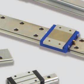


296 LINEAR MOTION
297 Table of Contents Linear Guides Applications... Page I-1 Product Selection Tips... Page I-2 Interchange... Page I-3 Types... Page I-5 NH Series (Replacement for LH Series, Size 15-65) Nomenclature... Page I-7 AN, BN Models... Page I-9 AL, BL Models... Page I-11 EM, GM Models... Page I-13 NS Series (Replacement for LS Series) Nomenclature... Page I-15 CL, AL Models... Page I-17 JM, EM Models... Page I-19 PU Series PE Series Nomenclature... Page I-21 TR, AR, AL, UR, BL Models... Page I-23 Nomenclature... Page I-25 AR, TR, UR, BR Models... Page I-27 LW Series Nomenclature... Page I-29 EL Model... Page I-31 RA Series Nomenclature... Page I-33 AN, BN Models... Page I-35 AL, BL Models... Page I-37 EM, GM Models... Page I-39 Assembly and Mounting... Page I-41 Grease... Page I-43 K1 Maintenance-Free Lubrication System... Page I-47 Precision Ground Ball Screw Nomenclature... Page I-53 Specification Sheet for New Applications... Page I-54 Compact FA Quickship Ball Screws Features... Page I-55 Availability... Page I-56 Rolled Ball Screw Nomenclature... Page I-57 Product Classification... Page I-58 Ball Screw Support Units Nomenclature... Page I-59 Categories... Page I-60 Support Units for Light Load... Page I-61 Support Units for Heavy Load... Page I-61 Support Units for Light Load... Page I-62 and Small Equipment Monocarrier Features... Page I-63 Applications... Page I-64 MCM Series Monocarrier Nomenclature... Page I-65 Applications... Page I-65 Accuracy Grade and Limitations... Page I-66 Standard Combinations of Stroke... Page I-67 and Ball Screw Lead Basic Load Rating... Page I-68 MCH Series Monocarrier Nomenclature... Page I-69 Applications... Page I-69 Accuracy Grade and Limitations... Page I-70 Standard Combinations of Stroke... Page I-71 and Ball Screw Lead Basic Load Rating... Page I-72 Unit Conversions... Page I-52 LINEAR MOTION
 have been discontinued and replaced by NSK s next generation NH and NS Linear Guide series, which are dimensionally interchangeable with the LH and")


298 Linear Guides Linear Guides are designed for high precision motion and control applications. They provide greater rigidity and higher load capacity than shaft and bushing designs. The LH & LS Series (except sizes LH08, 10, and 12) have been discontinued and replaced by NSK s next generation NH and NS Linear Guide series, which are dimensionally interchangeable with the LH and LS series, respectively. The NH and NS Linear Guides have an improved internal design that increases load ratings, lowers noise, improves smoothness, and increases high-speed capabilities. The NH and NS Linear Guides are completely interchangeable with the LH and LS series, respectively. When replacing individual LAH or LAS sliders (carriages), the new NAH or NAS sliders (carriages) can be installed on the existing NSK L1H or L1S rails. Some of the industries served - machine tool, robotics, medical and aerospace - require smooth travel and high accuracy. Applications Machine Tool (CNC, EDM, Laser Cutting, Water Jet, Lathes) Woodworking (Routers) Glasscutting Testing Equipment Medical (Diagnostic Equipment, Lab Automation, Genomics, Biotechnology) CMM Factory Automation Semiconductor (Wafer Handling, PCB Drilling, LCD Etching, Testing Equipment) I-1 LINEAR MOTION
299 Linear Guide Product Selection Tips To help in the selection of linear guides, NSK has come up with a series of questions that need to be asked in order to determine the appropriate NSK product. What is the application? What is the NSK or competitor parts number? What type of carriage or bearing style is needed for this application: Tapped or Through Hole, Square or Flange style? What is the rail length required for this application? How many carriages or bearings are needed per rail? Are there any special accuracy and preload requirements? What are the loading conditions of the application? Please provide both Static & Dynamic loads. What are the delivery requirements? Can you provide us with a drawing of the part to be purchased? Lubrication Method - Is the K1 lubrication system of interest for this application? What is the G dimension of rail? G Dimension Information: A G dimension is required to assure proper mounting to existing application. The G dimension is the measurement from start of the rail to the center of the first bolt hole. In instances where rail will be butted together, please contact NSK for assistance. G1 G2 LINEAR MOTION I-2
300 Linear Guides Interchange Description Carriage Part Rail Part Assembly Part 1 - Linear Guide Series NSK THK THOMSON Old New SKF BOSCH - REXROTH (STAR) INA NH HSR (SHS) CG 511 LLRHS/LLTHS R16 1 KUVE##/KWVE##/TKVD## 2 NS SR (SSR) LLRHS R161 KUVE##/KWVE##/TKVD## 2 LW HRW R1671 KUVE##-WKWVE##-W/TKVD##-W PU RSR CD TSR-Z LLMHS R0442/R0444 KUEM##/KWEM##/TKDM## PE RSR W LLMWS TSR-WZ LLMWS R0441/R0443 KUEM##-W/KWEM##-W/TKDM##-W 1 See Carriage Section for Exact Series for Bosch - Rexroth (STAR) 2 See Carriage and Rail Section for Exact Series for INA 2 - Linear Guide Series (rail width) NSK THK THOMSON SKF BOSCH - REXROTH (STAR) INA indicated rail width Same as NSK 3 - Linear Guide Carriage Styles ## = size (rail width) Same as NSK with the exception of the CD series Interchange NSK THK THOMSON SKF BOSCH - REXROTH Same as NSK See Table Same as NSK NSK THK THOMSON BOSCH - REXROTH SKF Common Less Common Old New (STAR) INA NAH##AN HSR##R (SHS##R/V) HSR##TR/TRX/CR CG##CE 511H##E LLRHC##R/U (20,45) R1621 KWVE##-B-H NAH##BN HSR##LR (SHS##LR/LN) HSR##HTR/HR CG##DE 511H##F LLRHC##LR R1624 KWVE##-B-HL NAH##EM HSR##A/B/CA/CB (SHS##C) HSR##TA CG##AA 511H##A LLRHC##A R1651 KWVE##-B NAH##GM HSR##HA/LA/HB/LB (SHS##LC) HSR##HTA/HTB CG##BA 511H##B LLRHC##LA R1653 KWVE##-BL NAH##AL (SHS##V) 511H##C (25,30,35) LLRHC##U (25,30,35) R1622 (except R1622-1) KWVE##-B-S NAH##BL (SHS##LV) 511H##D (25,30,35) R1623 KWVE##-B-SL NAS##EM SR##TB (SSR##XTB) R1693 NAS##AL SR##W (SSR##XW) SR##TX/WY (SSR##XWY) LLRHC15U R1694/R NAS##CL SR##V (SSR##XV) SR##SX/VY (SSR##XVY) LLRHC##SU (15,30,35) R1662/R1666/R1664 KWVE##-B-ESC NAS##JM SR##SB LLRHC##SA R1663 KWVE##-B-EC LAW##EL HRW##CA/CR R1671 KWVE##-W PAU##AR RSR07M/RSR07N LLMHC##TA KWEM##- PAU##TR RSR05M/##N (5,9) RSR09KM/RSR12VM LLMHC##TA R0442 KWEM##- PAU##UR RSR12N R0444 KWEM##-L PAU##AL RSR15VM KWEM##- PAE##AR RSR05WM/##WN (5,12,15) RSR12WVM/RSR15WVN LLMWC##TA R0443 KWEM##-W PAE##TR RSR07WM/##WN (7,9) RSR09WVM LLMWC##TA R0441 KWEM##-WL (STAR) NAH 20 AN Z HSR 20 R C1 511 H 20 C 1 LLRHC 20 A- T1 R KWVE 20 - B-H G4 V , N1H 20 XXXX Z HSR 20+ XXXXL 521 H 20 A +XXXX LLRHR 20x XXXX P5 R XXXX TKVD 20 - G4 / XXXX ,4 2 X NH 25 XXXX AN C X PC Z HSR 20 R 2 SS C1 +XXXXL LLRHS 20 A 2 T1 XXXX P5 KUVE 20 - B-H W2 G4 V2 / XXXX N/A N/A The competitive manufacturers are provided for a convenient source of unit substitution. They can be considered interchangeable in most instances, but for special applications, please consult NSK Engineering. NSK assumes no liability with respect to errors or omissions. BOSCH - REXROTH (STAR) Series BOSCH Size NSK Size R16## 1 15 R16## 8 20 R16## 2 25 R16## 7 30 R16## 3 35 R16## 4 45 R16## 5 55 R16## 6 65 R R R R044# 7 07 R044# 8 09 R044# 2 12 R044# 5 15 INA I-3 LINEAR MOTION
301 4 - Linear Guide Rail Length (mm) ## = size (rail width) XXXX = length NSK THK Old THOMSON New SKF BOSCH - REXROTH (STAR) N1H##XXXXZ HSR##+XXXXL RG##NLXXXX 521H##A+XXXX LLRHR##xXXXXP5 R1605-###-XXXX 1 TKVD##-##/XXXX 2 N1S##XXXXZ SR##+XXXXL LLRHR##xXXXXP5 R1605-###-XXXX 1 TKVD##-##/XXXX 2 L1W##XXXXZ HRW##+XXXXL R1605-###-XXXX TKVD##-W-##/XXXX P1U##XXXXZ RSR##+XXXXL RD##HLXXXX TSR##Z+XXXX LLMHR##xXXXXP5 R0445-###-XXXX TKDM##-##/XXX P1E##XXXXZ RSR##W+XXXXL TSR##WZ+XXXX LLMWR##xXXXXP5 R0455-###-XXXX 1 See Carriage Section for Exact Series for Bosch - Rexroth (STAR) 2 See Carriage and Rail Section for Exact Series for INA INA 5 - Carriages The number following the carriage style equals the number of carriages per rail. 6 - Accuracy Class NSK THK THOMSON SKF BOSCH - REXROTH (STAR) PC (interchangeable) BLANK N P5 4- (N) G3 P6 H H P3 3- (H) P5 P P P1 2- (P) G2 P4 SP S P01 1- (XP/SP) G1 P3 UP U P (UP) INA 7 - Preload NSK (Matched Assembly) THK Old THOMSON New SKF BOSCH - REXROTH (STAR) T or Z0 BLANK A 0 T0 -#9# Z or Z1 C1 B 1 T1 -#1# V1 Z2 C1 B 1 T1 -#2# V2 H or Z3 C0 C 2 T2 -#3# V3 Z4 C0 C 3 T3 V4 INA 8 - Seals NSK THK Old THOMSON New SKF BOSCH - REXROTH (STAR) Standard (End Seals) UU-End Seals Standard Standard -10 or -20 or -22 Standard (Side Seals) SS-Side Seals+End Seals LDS Standard Standard -10 or -20 or -22 -P (Protector/Scraper) ZZ-End, Side, Inner Seals and Scraper ZZ Z S1 None -D (Double End Seals) DD-Double End, Side, and Inner Seals DD W S2 None -DP (Double End Seals, Protector) KK-Double End, Side, Inner Seals and Scraper KK WZ S3 None INA Separate Part s Lubrication Systems NSK THK THOMSON SKF -K1 QZ LL Standard External to the Carriage External to the Carriage External to the Carriage Internal Foam Insert LINEAR MOTION I-4

. Suitable for high speed applications. NS Series 50 50 Replaces the old LS series.")


302 Types of Linear Guides Series NH Series Features Replaces the old LH series, size Dimensionally equivalent to LH. NSK basic series General versatility for heavy-duty applications Large load carrying capacity against vertical direction Stainless steel is available (#15 30). Suitable for high speed applications. NS Series Replaces the old LS series. Dimensionally equivalent to LS. Compact designed NSK basic series General versatility for fine application Large load carrying capacity against vertical direction Stainless steel is available (#15 35). Suitable for high speed applications. RA Series A roller guide with super high load capacity and rigidity Super high accuracy and smooth motion Highly dust proof and maintenance free LW Series Wide rail type linear guide Ideal for use of single rail Large load carrying capacity against vertical direction PU Series Lightweight designed miniature linear guide Reduced noise and smooth motion High corrosion resistance (stainless steel) PE Series Lightweight designed wide rail miniature linear guide Ideal for use of single rail Reduced noise and smooth motion High corrosion resistance (stainless steel) I-5 LINEAR MOTION
303 AN, BN AL, BL Ball Slide Model AN, AL BN, BL Size Size & Preload Preload Dimension Table L1 L1 EM, GM EM L1 GM L1 NH Slight preload ZZ Page I-9 - I-14 AL, CL AL CL Size Preload L1 L1 EM, JM EM L1 JM L1 NS Slight preload ZZ Page I-17 - I-20 AL, BL AN, BN AL, AN BL, BN Size Preload L1 L1 RA15 RA20 RA25 EM, GM EM L1 GM L1 RA30 RA35 RA45 Medium preload Z Page I-35 - I-40 RA55 RA65 EL EL Size LW17 Preload LW21 LW27 LW35 Slight preload ZZ Page I-31 - I-32 AL, TR, UR, BL AL, TR BL, UR LW50 Size Preload L1 L1 PU05 PU07 PU09 PU12 PU15 Maximum clearance 3 μm ZT Page I-23 - I-24 AR, TR, UR, BR AR, TR L1 BR, UR L1 Size PE05 PE07 PE09 PE12 PE15 Preload Maximum clearance 3 μm ZT Page I-27 - I-28 LINEAR MOTION I-6


304 Linear Guides: NH Series (Replacement for the LH Series, Size 15-65) Part Example for Ball Slide Only Interchangeable Ball Slide Ball Slide Shape Code Preload Z: Slight Preload H: Medium Preload No Code: Fine Clearance NAH 30 AN S Z -K1 Size Material Code S: Stainless Steel No code: Special High Carbon Steel Option Code K1: Equipped With NSK K1 K2: Two K1 Lubrication Units D: Double Seals P: Protector Plate I-7 LINEAR MOTION
305 Reference Part for Rail Only Interchangeable Rail Rail Length (mm) Preload Z: Slight Preload -01Z: Buttable Rail N1H S Z Size Material Code No Code: Special high carbon steel (NSK Standard) S: Stainless Steel Reference Part for Interchangeable Assembly (Ball Slide + Rail) Series Rail Length (mm) Material/ Surface Treatment Blank: Standard Carbon Steel S: Stainless Steel A: Carbon Steel + Armoloy B: Stainless Steel + Armoloy NSK Control (*** is required when making inquiries) Preload Z: Slight Preload (standard) No Code: Slight Clearance NH AN 2 *** PC Z Size Shape /Height of Ball Slides Per Rail Accuracy PC: Only PC Grade is Available KC: With NSK K1 Plastic Cap for Rail Mounting Hole Linear Guide Model No. Rail Mounting Bolt Size Cap. No. for Rail Mounting Hole NH15 M4 L NH20 M5 L NH25 M6 L NH30 NH35 M8 L NH45 M12 L NH55 M14 L NH65 M16 L Brass Cap for Rail Mounting Hole Linear Guide Model No. Rail Mounting Bolt Size Cap. No. for Rail Mounting Hole NH20 M5 L NH25 M6 L NH30 NH35 M8 L NH45 M12 L LINEAR MOTION I-8
306 Linear Guides: NH Series (Replacement for the LH Series) Ball Slide Models: AN, BN Front View of AN and BN Types Side View of BN Type Model No. NH15AN NH15BN NH20AN NH20BN NH25AN NH25BN NH30AN NH30BN NH35AN NH35BN NH45AN NH45BN NH55AN NH55BN NH65AN NH65BN Assembly Height H E W 2 Width Length W L Mounting hole Notes: 1) External appearance of stainless steel ball slides differs from those of carbon steel ball slides. Ball slide Grease fitting Width Height B J M Pitch l L 1 K T Hole size T 1 N W 1 H M Ø M M M M M M M M M Rc1/ M Rc1/ M Rc1/ I-9 LINEAR MOTION
307 Side view of AN type Unit: mm Rail Basic load rating Weight Pitch Mounting G Max. length 2) Dynamic Static Static moment (N m) Ball slide Rail bolt hole L 0max [50km] [100km] C 0 M PO M YO F d D h (reference) ( ) for stainless C 50(N) C 100(N) (N) M RO (One slide) (Two slides) (One slide) (Two slides) (kg) (kg/m) (1 800) (3 500) (3 500) (3 500) ) The basic load rating comply with the ISO standard. (ISO and ISO ) C 50 : the basic dynamic load rating for 50 km rating fatigue life, C 100 : the basic dynamic load rating for 100 km rating fatigue life The basic static load rating shows static permissible load. LINEAR MOTION I-10
308 Linear Guides: NH Series (Replacement for the LH Series) Ball Slide Models: AL, BL Front View of AL and BL Types Side View of BL Type Model No. NH25AL NH25BL NH30AL NH30BL NH35AL NH35BL NH45AL NH45BL NH55AL NH55BL Assembly Height H E W 2 Width Length W L Mounting hole Notes: 1) External appearance of stainless steel ball slides differs from those of carbon steel ball slides. Ball slide Grease fitting Width Height B J M Pitch l L 1 K T Hole size T 1 N W 1 H M M M M M M M Rc1/ M Rc1/ I-11 LINEAR MOTION
309 Side view of AL type Unit: mm M YO Rail Basic load rating Weight 2) Pitch Mounting G Max. length Dynamic Static Static moment (N m) bolt hole L 0max [50km] [100km] C 0 M PO Ball slide Rail F d D h (reference) ( ) for stainless C 50 (N) C 100 (N) (N) M RO (One slide) (Two slides) (One slide) (Two slides) (kg) (kg/m) (3 500) (3 500) ) The basic load rating comply with the ISO standard. (ISO and ISO ) C 50 : the basic dynamic load rating for 50 km rating fatigue life, C 100 : the basic dynamic load rating for 100 km rating fatigue life The basic static load rating shows static permissible load. LINEAR MOTION I-12
310 Linear Guides: NH Series (Replacement for the LH Series) Ball Slide Models: EM, GM Front View of EM and GM Types Side View of GM Type MRO W B 4-M Q 2 pilot drill MYO H K T E W2 W1 Model No. NH15EM NH15GM NH20EM NH20GM NH25EM NH25GM NH30EM NH30GM NH35EM NH35GM NH45EM NH45GM NH55EM NH55GM NH65EM NH65GM Assembly Height H E W 2 W Width Length L Notes: 1) Parenthesized dimensions are for items made of stainless steel. 2) External appearance of stainless steel ball slides differs from those of carbon steel ball slides. Mounting hole Ball slide Grease fitting Width B J M Pitch l Q 2 L 1 K T Hole size T 1 N W 1 H M Ø M M M (M ) 86 (12) M M (M ) 98 (15) M M M M Rc1/ M Rc1/ M Rc1/ Height I-13 LINEAR MOTION
311 Side view of EM type Unit: mm Rail Basic load rating Weight Pitch Mounting G Max. length 3) Dynamic Static Static moment (N m) Ball slide Rail bolt hole L M PO M YO F d D h (reference) ( (kg/m) 0max ) for stainless [50km] C 50 (N) [100km] C 100 (N) C 0 (N) M RO (One slide) (Two slides) (One slide) (Two slides) (kg) (1 800) (3 500) (3 500) (3 500) ) The basic load rating comply with the ISO standard. (ISO and ISO ) C 50 : the basic dynamic load rating for 50 km rating fatigue life, C 100 : the basic dynamic load rating for 100 km rating fatigue life The basic static load rating shows static permissible load. LINEAR MOTION I-14


312 Linear Guides: NS Series (Replacement for the LS Series) Part Example for Ball Slide Only Interchangeable Ball Slide Ball Slide Shape Code Preload Z: Slight Preload No Code: Fine Clearance NAS 30 AL S Z -K1 Size Material Code S: Stainless Steel No code: Special High Carbon Steel (NSK standard) Option Code K1: Equipped with NSK K1 K2: Two K1 Lubrication Units D: Double Seals P: Protector Plate I-15 LINEAR MOTION
313 Reference Part for Rail Only Interchangeable Rail Rail Length (mm) Material/Code No Code: Special High Carbon Steel (NSK Standard) S: Stainless Steel N1S S Z Size Rail Shape No Code: Normal T: The Rail Mounting Bolt Hole M4 for NSI5 Preload Z: Slight Preload -01Z: Buttable Rail Reference Part for Assembly (Ball Slide + Rail) Series Rail Length (mm) Material/ Surface Treatment Blank: Standard Carbon Steel S: Stainless Steel A: Carbon Steel + Armoloy B: Stainless Steel + Armoloy NSK Control (*** is required when making inquiries) Preload Z: Slight Preload (standard) No Code: Slight Clearance NS AL 2 *** PC Z Size Shape /Height of Ball Slides Per Rail Accuracy PC: Interchangeable KC: With NSK K1 Plastic Cap for Rail Mounting Hole Brass Cap for Rail Mounting Hole Linear Guide Model No. Rail Mounting Bolt Size Cap. No. for Rail Mounting Hole NS15 M3 L NS20 M5 L NS25 NS30 M6 L NS35 M8 L Linear Guide Model No. Rail Mounting Bolt Size Cap. No. for Rail Mounting Hole NS20 M5 L NS25 NS30 M6 L NS35 M8 L LINEAR MOTION I-16
314 Linear Guides: NS Series (Replacement for the LS Series) Ball Slide Models: CL, AL Front View of AL and CL Types Side View of CL Type Model No. NS15CL NS15AL NS20CL NS20AL NS25CL NS25AL NS30CL NS30AL NS35CL NS35AL Assembly Height H E W 2 Width Length W L Mounting hole Ball slide Notes: 1) External appearance of stainless steel ball slides differs from those of carbon steel ball slides. 2) The basic load rating comply with the ISO standard. (ISO and ISO ) C 50 : the basic dynamic load rating for 50 km rating fatigue life, C 100 : the basic dynamic load rating for 100 km rating fatigue life The basic static load rating shows static permissible load. Grease fitting Width Height B J M Pitch l L 1 K T Hole size T 1 N W 1 H M Ø M M M M M M M M I-17 LINEAR MOTION
315 Side View of AL Type Unit: mm Rail Basic load rating Weight Pitch Mounting G Max. length 2) Dynamic Static Static moment (N m) Ball slide Rail bolt hole L 0max [50km] [100km] C 0 M PO M YO F d D h (reference) ( ) for stainless C 50(N) C 100(N) (N) M RO (One slide) (Two slides) (One slide) (Two slides) (kg) (kg/m) 60 * (1 700) (3 500) (3 500) (3 500) (3 500) *) Standard rail mounting bolt hole for NS15 is specified as hole for M3 (3.5 x 6 x 4.5). Please contact NSK to request a different hole for M4 (4.5 x 7.5 x 5.3). LINEAR MOTION I-18
316 Linear Guides: NS Series (Replacement for the LS Series) Ball Slide Models: JM, EM Front View of JM and EM Types Side View of JM Type M RO W B (N) L L1 2-M ( Q2 pilot drill) T1 M YO H K T E W2 W1 Model No. NS15JM NS15EM NS20JM NS20EM NS25JM NS25EM NS30JM NS30EM NS35JM NS35EM Assembly Height H E W 2 W Width Length L Notes: 1) External appearance of stainless steel ball slides differs from those of carbon steel ball slides. 2) Parenthesized dimensions are for items made of stainless steel. Mounting hole Ball slide Grease fitting Width Height B J M Pitch l Q 2 L 1 K T Hole size T 1 N W 1 H M Ø M (M ) M M (M ) 60 (12) M M (M ) 71 (15) M M (M ) 80 (15) M I-19 LINEAR MOTION
317 Side View of EM Type M PO (N) L L1 J 4-M ( Q2 pilot drill) φd T1 H1 h φd G F n F (G) L0 Unit: mm Rail Basic load rating Weight Pitch Mounting G Max. length 3) Dynamic Static Static moment (N m) Ball slide Rail bolt hole L 0max [50km] [100km] C 0 M PO M YO F d D h (reference) ( ) for stainless C 50(N) C 100(N) (N) M RO (One slide) (Two slides) (One slide) (Two slides) (kg) (kg/m) 60 * (1 700) (3 500) (3 500) (3 500) (3 500) ) The basic load rating comply with the ISO standard. (ISO and ISO ) C 50 : the basic dynamic load rating for 50 km rating fatigue life, C 100 : the basic dynamic load rating for 100 km rating fatigue life The basic static load rating shows static permissible load. *) Standard rail mounting bolt hole for NS15 is specified as hole for M3 (3.5 x 6 x 4.5). Please contact NSK to request a different hole for M4 (4.5 x 7.5 x 5.3). LINEAR MOTION I-20

318 Linear Guides: PU Series Part Example for Ball Slide Only Random-Matching Ball Slide Shape /Height Accessories K1: With NSK K1 PAU 15 AL S -K1 Size S: Stainless Steel I-21 LINEAR MOTION
319 Reference Part for Rail Only Random -Matching Rail Rail Length (mm) Butting Rail Specification Z: Non-butting -01Z: Butting Rail P1U S Z Size Material/Surface Treatment S: Stainless Steel Reference Part for Assembly (Ball Slide + Rail) Series Rail Length (mm) Material / Surface Treatment K: Stainless Steel H: Stainless Steel + Surface Treatment NSK Control (*** is required when making inquiries) Preload T: Fine Clearance (standard) PU AL K 2 *** PC T Size Shape /Height of Ball Slides Per Rail Accuracy PC: Only PC Grade is Available K6: With NSK K1 Plastic Cap for Rail Mounting Hole Linear Guide Model No. PU09, PU12, PU15, PE09 Rail Mounting Bolt Size Cap. No. for Rail Mounting Hole M3 L LINEAR MOTION I-22
320 Linear Guides: PU Series Ball Slide Models: TR, AR, AL, UR, BL Front View MRO B1 W B 4-M l M YO H K T E B3 W2 W1 PU09, 12 MRO B1 W B 4-M l T MYO H K E B3 W2 W1 PU15 Assembly Ball Slide Model No. Height Width Length Mounting Hole H E W 2 W L B J M x pitch x l B 1 L 1 J 1 K T Grease Fitting Mounting Hole Size T 1 N PU09TR M PU09UR PU12TR M PU12UR PU15AL M f (3.6) PU15BL I-23 LINEAR MOTION
321 Side View MPO L φd J1 L1 J H1 h G φ d F n F (G) L0 PU09, 12 MPO N L φd T1 J1 L1 J H1 h φ d G F n F (G) L0 n = (number of holes)-1 PU15 Width Height Pitch Mounting Bolt Hole W 1 H 1 F Rail Basic Load Rating Ball Diameter Max Length Dynamic Static Static Moment (Single Rail) C C 0 M R0 M P0 d x D x h B 3 G L 0max (N) (N) (N m) (N m) Weight M Y0 Ball Slide (N m) D w (g) Note: Basic dynamic load rating C is a load that allows for a 50-km rating fatigue life and is a vertical and constant load on the ball slide mounting surface. To convert C to C100 for a 100-km fatigue life, divide C by Unit: mm Rail (g/100 mm) LINEAR MOTION I-24

322 Linear Guides: PE Series Part Example for Ball Slide Only Random-Matching Ball Slide Shape /Height Accessories K1: With NSK K1 PAE 15 AL S -K1 Size S: Stainless Steel I-25 LINEAR MOTION
323 Reference Part for Rail Only Random -Matching Rail Rail Length (mm) Butting Rail Specification Z: Non-butting -01Z: Butting Rail P1E S Z Size Material /Surface Treatment S: Stainless Steel Reference Part for Assembly (Ball Slide + Rail) Series Rail Length (mm) Material/ Surface Treatment K: Stainless Steel H: Stainless Steel + Surface Treatment NSK Control (*** is required when making inquiries) Preload T: Fine Clearance (standard) PE AL K 2 *** PC T Size Shape /Height of Ball Slides Per Rail Accuracy PC: Only PC Grade is Available KC: With NSK K1 Plastic Cap for Rail Mounting Hole Linear Guide Model No. PU09, PU12, PU15, PE09 Rail Mounting Bolt Size Cap. No. for Rail Mounting Hole M3 L LINEAR MOTION I-26
324 Linear Guides: PE Series Ball Slide Models: AR, TR, UR, BR Front View MRO W 4-M l B1 B MYO H K T E B3 W2 W1 PE09, 12 MRO W 4-M l B1 B MYO H K E B3 B2 W2 W1 PE15 Assembly Ball Slide Model No. Height Width Length Mounting Hole Grease Fitting H E W 2 W L B J M x pitch x l B 1 L 1 J 1 K T Mounting Hole Size T 1 N PE09TR M PE09UR PE12AR M PE12BR PE15AR M f (3.3) PE15BR I-27 LINEAR MOTION
325 Side View MPO φd J1 L L1 J H1 h G φ d F n F L0 (G) PE09, 12 MPO N L J1 L1 J φd T1 H1 h G φ d F n F L0 n = (number of holes)-1 (G) PE15 Unit: mm Width Height Pitch W 1 H 1 B 2 F Rail Basic Load Rating Ball Diameter Mounting Max Length Dynamic Static Static Moment Bolt Hole (Single Rail) C C 0 M R0 M P0 d x D x h B 3 G L 0max (N) (N) (N m) (N m) Weight M Y0 Ball Slide (N m) D w (g) Note: Basic dynamic load rating C is a load that allows for a 50-km rating fatigue life and is a vertical and constant load on the ball slide mounting surface. To convert C to C 100 for a 100-km fatigue life, divide C by Rail (g/100m) LINEAR MOTION I-28
326 Linear Guides: LW Series Part Example for Ball Slide Only Random-Matching Ball Slide Shape /Height Accessories K1: With NSK K1 F: Fluoride Low-Temperature Chrome Plating + AS2 Grease F50: Fluoride Low-Temperature Chrome Plating + LG2 Grease LAW 17 EL Z -K1 Size Preload Z: Slight Preload (standard) No Code: Slight Clearance I-29 LINEAR MOTION
327 Reference Part for Rail Only Random -Matching Rail Rail Length (mm) Material/Surface Treatment NSK Control (*** is required when making inquiries) Z: Standard L1W L C N *** PC Z Size Shape L: Standard Butting Rail Specification N: Non-butting L: Butting Accuracy PC: Only PC Grade is Available Reference Part for Assembly (Ball Slide + Rail) Series Rail Length (mm) Material/ Surface Treatment NSK Control (*** is required when making inquiries) Preload Z: Slight Preload (standard) No Code: Slight Clearance LW EL C 2 *** PC Z Size Shape /Height of Ball Slides Per Rail Accuracy PC: Only PC Grade is Available KC: With NSK K1 Plastic Cap for Rail Mounting Hole Brass Cap for Rail Mounting Hole Linear Guide Model No. Rail Mounting Bolt Size Cap. No. for Rail Mounting Hole LW17 M4 L LW21 M4 L LW27 M4 L LW35 M6 L LW50 M8 L Linear Guide Model No. Rail Mounting Bolt Size Cap. No. for Rail Mounting Hole LW17 M4 L LW21 M4 L LW27 M4 L LW35 M6 L LW50 M8 L LINEAR MOTION I-30
328 Linear Guides: LW Series Ball Slide Model: EL Front View of EL Type M RO B 1 W B 2-M ( φq 2 pilot drill) 4-M l ( φ Q 2 pilot drill) H K T l 2 M YO E B 3 B 2 W 2 W 1 Assembly Ball Slide Model No. Height Width Length Mounting Hole Grease Fitting H E W 2 W L B J M x pitch x l l 2 Q 2 B 1 L 1 J 1 K T Hole Size T 1 N LW17EL M f LW21EL M M LW27EL M M LW35EL M M LW50EL M Rc1/ I-31 LINEAR MOTION
329 Side View of EL Type M PO N J 1 L L 1 J φd T 1 H 1 h φ d G F n F L 0 n = (number of holes)-1 (G) Width Height Pitch W 1 H 1 B 2 F Rail Basic Load Rating Ball Diameter Mounting G Max length Dynamic Static Static Moment Bolt Hole (recommended) L 0max (N) (N) (N m) (N m) (N m) D w (Single Rail) Ball C C 0 M R0 M P0 M Y0 Slide d x D x h B 3 (kg) Unit: mm Weight Rail (kg/m) Note: Basic dynamic load rating C is a load that allows for a 50-km rating fatigue life and is a vertical and constant load on the ball slide mounting surface. To convert C to C100 for a 100-km fatigue life, divide C by LINEAR MOTION I-32

330 Linear Guides: RA Series Part Example for Roller Slide Only Interchangeable Roller Slide Shape /Height Preload Z: Interchangeable with Preload RAA 35 AN K6 Z Size Accuracy P6: Precision K6: Precision with NSK K1 I-33 LINEAR MOTION
331 Reference Part for Rail Only Interchangeable Rail Rail Length (mm) Butting Rail -01Z: Butting Rail Z: Non-butting Rail R1A Z Size Material/Surface Treatment Blank: Standard Carbon Steel Reference Part for Assembly (Roller Slide + Rail) Series Rail Length (mm) Material/ Surface Treatment C: Carbon Steel (NSK standard) NSK Control (*** is required when making inquiries) Preload 1: Slight Preload, Z1 3: Medium Preload, Z3 Z: Interchangeable, Medium Preload RA AN C 2 *** P6 3 Size Shape /Height of Roller Slides Per Rail Accuracy P6: Without NSK K1 K6: With NSK K1 Plastic Cap for Rail Mounting Hole Brass Cap for Rail Mounting Hole Linear Guide Model No. Rail Mounting Bolt Size Cap. No. for Rail Mounting Hole RA25 M6 L RA30 M8 L RA35 M8 L RA45 M12 L RA55 M14 L RA65 M16 L Linear Guide Model No. Rail Mounting Bolt Size Cap. No. for Rail Mounting Hole RA25 M6 L RA30 M8 L RA35 M8 L RA45 M12 L RA55 M14 L RA65 M16 L LINEAR MOTION I-34
332 Linear Guides: RA Series Roller Slide Models: AN, BN Front View of AN and BN Types Upper View of AN and BN Types MRO B1 W B 6-M pitch depth l MYO T H (K) E W2 B3 W1 Model No. Height Assembly Width Length Mounting Hole H E W 2 W L B J M x pitch x l Roller Slide B 1 L 1 J 1 K T Grease Fitting Mounting Hole Size T 1 N RA15AN M RA15BN RA20AN M RA20BN RA25AN M RA25BN M RA30AN M M RA30BN RA35AN M M RA35BN RA45AN M Rc1/ RA45BN RA55AN M Rc1/ RA55BN RA65AN M Rc1/ RA65BN I-35 LINEAR MOTION
333 Side View of AN and BN Types MPO (N) J1 L L1 J φd T1 H1 h G φ d F n F (G) L0 n = (number of holes)-1 Unit: mm Rail Width Height Pitch Mounting Bolt Hole W 1 H 1 F d x D x h B 3 G Max Length (Single Rail) L 0max Basic Load Rating Dynamic Static Static Moment C (N) C 0 (N) M R0 (N m) M P0 (N m) M Y0 (N m) Weight Roller Slide (kg) (30) (30) Rail (kg/m) Note: Basic load rating complies with ISO standards (ISO , ISO ). If above basic dynamic load rating (100-km rating) is converted into 50-km rating, use the following formula: C50 km =1.23 C 100 km. LINEAR MOTION I-36
334 Linear Guides: RA Series Roller Slide Models: AL, BL Front View of AL and BL Types Upper View of AL and BL Types MRO B1 W B 6-M pitch depth l MYO H (K) T E B3 W2 W1 Assembly Roller Slide Model No. Height Width Length Mounting Hole H E W 2 W L B J M x pitch x l B 1 L 1 J 1 K T Grease Fitting Mounting Hole Size T 1 N RA15AL M RA15BL RA25AL M M RA25BL RA30AL M M RA30BL RA35AL M M RA35BL RA45AL M Rc1/ RA45BL RA55AL M Rc1/ RA55BL I-37 LINEAR MOTION
335 Side View of AL and BL Types MPO (N) L J1 L1 J φd T1 H1 h G φ d F n F (G) L0 n = (number of holes)-1 Rail Width Height Pitch Mounting Bolt Hole W 1 H 1 F d x D x h B 3 G Max Length (Single Rail) L 0max Basic Load Rating Dynamic Static Static Moment C (N) C 0 (N) M R0 (N m) M P0 (N m) M Y0 (N m) Weight Roller slide (kg) (30) Note: Basic load rating complies with ISO standards (ISO , ISO ). If above basic dynamic load rating (100-km rating) is converted into 50-km rating, use the following formula: C50 km =1.23 C 100 km. Unit: mm Rail (kg/m) LINEAR MOTION I-38
336 Linear Guides: RA Series Roller Slide Models: EM, GM Front View of EM and GM Types Upper View of EM and GM Types MRO MYO T B1 (l2) W B φ Q l1 6-M pitch J3 J2 H (K) E B3 W2 W1 2-M pitch Model No. Height Assembly Width Length Mounting Hole M x pitch x l 1 H E W 2 W L B J J 2 (l 2 ) Roller Slide Q x l 1 (l 2 ) B 1 L 1 J 1 J 3 K T Grease Fitting Mounting Hole Size T 1 N RA15EM M RA15GM (6.5) 60.2 RA20EM M RA20GM (8) 77.3 RA25EM M M RA25GM (11) (11) RA30EM M M RA30GM (12.5) (12.5) RA35EM M M RA35GM (7) (7) RA45EM M Rc1/ RA45GM (10.5) (10.5) RA55EM M Rc1/ RA55GM (13) (13) RA65EM M Rc1/ RA65GM (13) (13) I-39 LINEAR MOTION
337 Side View of EM and GM Types MPO (N) L J 1 L1 J φd T1 H1 h G φ d F n F (G) L0 n = (number of holes)-1 Unit: mm Rail Width Height Pitch Mounting Bolt Hole W 1 H 1 F d x D x h B 3 G Max Length (Single Rail) L 0max Basic Load Rating Dynamic Static Static Moment C (N) C 0 (N) M R0 (N m) M P0 (N m) M Y0 (N m) Weight Roller slide (kg) (30) (30) Rail (kg/m) Note: Basic load rating complies with ISO standards (ISO , ISO ). If above basic dynamic load rating (100-km rating) is converted into 50-km rating, use the following formula: C50 km =1.23 C 100 km. LINEAR MOTION I-40
 grease for quick installation. 3.")

. Tighten the bolts in an order which enables the wrench to help push the rail against the mounting surface (see Fig. I.")

 Shoulder Height of Rail H Shoulder Height of Ball Slide H 15 0.5 4.0 4.5 20 0.5 4.5 5.0 25 0.5 5.0 5.0 30 0.5 6.")
338 Assembly and Mounting Assembly Interchangeable ball slides are shipped on (disposable) plastic provisional rails as shown in Fig I Wipe off anticorrosive oil from the rail. 2. All NSK slides come prepacked with Alvania 2 (AS2) grease for quick installation. 3. Align the rail with the bottom and side faces of the provisional rail while pushing the provisional rail lightly against the rail, slide the ball slide on the rail (Fig I.1). Fig I.1 Assembly of Ball Slide with Rail Mounting Procedure For Cases where Datum Surface Exists on the Bed 1. Lightly tighten the rail mounting bolts and then use the shoulder plate to secure rail datum surface against bed mounting surface (See Fig. I.4). 2. Tighten rail mounting bolts to their recommended torque value (see table below). Tighten the bolts in an order which enables the wrench to help push the rail against the mounting surface (see Fig. I.5 for example). Fig I.4 Positioning of Rail Mounting Method Shoulder Height and Corner Shape at Mounting Face When utilizing the reference surface to secure rail or ball slides to machine components the components must have the mounting face height (H', H") and corner chamfer (r) dimensions as listed in table below and illustrated in Figs. I.2 and I.3, to avoid interference. Shoulder Height and Corner Shape at Mounting Face Product No. Radius of corner r (max) Shoulder Height of Rail H Shoulder Height of Ball Slide H Recommended Torque for Rail Mounting Bolt (Case of Thermally Refined Bolt) unit: kgf cm Bolt Nominal No. Torque Bolt Nominal No. Torque M M M M M M M M M Fig I.5 Tightening Direction 3. Mount the adjust side rail, as shown in Fig. I.6, while checking rail parallelism. For the jig shown in Fig. I.6, stability will be improved by mounting it to a ball slide. Fig I.6 Parallelism Measurement with Jigs [1 kg cm= lb in] Fig I.2 Rail Datum Face Mounting Part Fig I.3 Ball Slide Datum Face Mounting Part 4. If dowel pins are being used they should be installed at this step. 5. Position the ball slides at specified intervals and mount the table gently. 6. Tighten ball slide mounting bolts of datum side while pushing the table so that the table and ball slide mounting reference surfaces are in contact. I-41 LINEAR MOTION
339 Indication of Installed Standard Side The datum face of each rail is indicated by a groove in the datum face or by an arrow mark on the end or top surface of the rail. Model Material High-Carbon Steel PU Series (all models) B PU12, 15 The datum face is indicated by a groove Stainless Steel B B D Lubrication Grease Lubrication NSK linear guides are packed with Alvania 2 (AS2) grease and can be used as delivered. The replenishment frequency is recommended to be once a year, but adjust the interval depending on the operational conditions. To Change Direction of Grease Fitting 1. Remove the grease fitting with a wrench. 2. Wind some sealing tape on the thread of the fitting, then insert it and tighten. Be careful not to over torque when tightening into the side of the plastic bearing end cap. Change of Fitting Position in Front/Back Direction 1. Remove the plug from the grease fitting mounting hole face B shown in Fig. I.1 with a hexagonal wrench. 2. Remove the grease fitting from face A and screw into hole face B. 3. In place of the removed fitting, insert the plug into the hole in the face A. Change Grease Fitting Position to Side Surface To mount the grease fitting on the end cap side face, or on the ball slide face, please consult NSK. Oil Lubrication Oil piping can be connected to the tapped hole from where the grease fitting was removed. The recommended lubrication oil supply quantity per ball slide per hour Q is given by the following formula, where N is the rail width number. Notes on Usage Separately packaged ball slide is mounted on a plastic temporary axis (disposable) as shown at left. 1. Wipe rust preventative oil from the rail. 2. Product is ready for immediate use. Comes prepacked with Alvania 2 (AS2) grease. 3. Note the groove mark which identifies the datum faces of ball slide and rail above. 4. Align the rail with the bottom and side faces of the provisional rail while pushing the provisional rail lightly against the rail, slide the ball slide on the rail (Fig I.1). Grease Fittings for NSK Ball Slides Type Linear Guide Model # Grease Fitting Part # Thread Spec. Drive NH15, NS15, LW17 L Dia. 3mm A NS, NS 20, 25, 30, 25 L M6X0.75MM B NS, NS 20, 25, 30, 25 L M6X0.75MM C NS, NS 20, 25, 30, 25 LW 21, 27, 35 L M6X0.75MM A NH 45, 55, 65 L PT 1/8 B NH 45, 55, 65 L PT 1/8 C NH 45, 55, 65, LW 50 L PT 1/8 Shape of Grease Fitting 3 M 6 x 0.75 or PT 1/8 (1) Drive-in type A type B type C type Q= N (ml/hr) (5) 150 Using NH45 as an example, N=45, and Q= 45 = 0.3(ml/hr) 150 (1) Applies only to model No. NH15, NS15 and LW17. LINEAR MOTION I-42
 are available. Grease in a bellows tube Composition of NSK Grease Unit Components and grease types are shown below.")

340 Grease NSK Grease Unit Replenish grease to NSK linear guides and ball screws by a manual type hand grease pump. Install the grease in bellows tube to the pump. Several types of grease (80 g) are available. Grease in a bellows tube Composition of NSK Grease Unit Components and grease types are shown below. Name (tube type) Reference NSK Grease NSK Grease AS2 (Brown) NSK GRS AS2 (80 g in a bellows tube) NSK Grease PS2 (Orange) NSK GRS PS2 NSK Grease LR3 (Green) NSK GRS LR3 NSK Grease LG2 (Blue) NSK GRS LG2 NSK Hand Grease Pump Unit Straight nozzle NSK HGP NZ1 -- (One nozzle is provided with the hand pump.) NSK HGP Grease nozzle (used with the hand grease pump) NSK straight nozzle NSK HGP NZ1 NSK chuck nozzle NSK HGP NZ2 NSK drive fitting nozzle NSK HGP NZ3 NSK point nozzle NSK HGP NZ4 NSK flexible nozzle NSK HGP NZ5 NSK flexible extension pipe NSK HGP NZ6 NSK straight extension pipe NSK HGP NZ7 I-43 LINEAR MOTION
341 NSK Greases (80 g in a bellows tube) Bellows tube NSK manual Grease Pump Unit NSK Hand Grease Pump Unit (Reference number: NSK HGP) Nozzle can also be set in this direction. Features Light-weight... Can be operated by one hand yet there is no worry of making a mistake. Inserting by high pressure... Insert at 15 Mpa. No leaking Does not leak when held upside down. Easy to change grease Simply attach the grease in bellows tube. Remaining grease Can be confirmed through slit on the tube. Several nozzles Five types of nozzles to choose from. Specifications Spout volume g/stroke Mass of main body g Overall length... About 200 mm Overall width... About 200 mm Grease tube outer diameter.... ø38.1 Accessory.... Several nozzles for a unique application can be attached Fig I.7 NSK Hand Grease Pump with NSK straight nozzle LINEAR MOTION I-44
342 Grease (cont.) Nozzles Nozzles that can be attached to NSK Hand Grease Pump Name Designation Code Use Dimensions NSK straight nozzle NSK HGP NZ1 Can be used with grease fitting A, B, and C under JIS B1575 standard. NSK chuck nozzle NSK HGP NZ2 Can be used with grease fitting A, B, and C under JIS B1575 standard. NSK fitting nozzle NSK HGP NZ3 Dedicated for the drive-in grease fitting. NSK point nozzle NSK HGP NZ4 Used for linear guides and ball screws which do not have grease fitting. Used to supply grease directly to the ball grooves, or through the opening of ball slide or ball slide to inside. NSK flexible nozzle NSK HGP NZ5 Tip of nozzle is flexible to supply grease in the areas where hand cannot reach. NSK flexible extension pipe NSK HGP NZ6 Flexible extension pipe connects the grease pump and the nozzle. NSK straight extension pipe NSK HGP NZ7 Straight extension pipe connects the grease pump and the nozzle. I-45 LINEAR MOTION
343 Grease Lubricant for Linear Guides and Ball Screws Type Thickener Base Oil Base Oil Kinematic Viscosity cst (40 0 C) Range of use Temperature ( 0 C) Purpose AS2 Lithium type Mineral oil ~110 For general use at high load. PS2 Lithium type Synthetic oil + mineral oil ~110 LR3 Lithium type Synthetic oil ~130 For low temperature and high frequency operation. For ball screws at high speed, medium load. LG2 Lithium type Mineral oil + synthetic hydrocarbon oil 30-20~70 For clean environment. NF2 Urea composite type Synthetic oil + mineral oil 27-40~100 For fretting resistance. Grease Nozzle used for NSK Linear Guide Linear Guide Model Tap Hole for Grease Fitting Standard Grease Fitting Straight Nozzle NZ1 Chuck Nozzles (two) NZ Drive-in Nipple Nozzles NZ3 Point Nozzle NZ4 Flexible Nozzle NZ5 NS15 ø 3 Drive-in type o NS20~35 M6 x 0.75 B type o o o NH15 ø 3 Drive-in type o NH20~35 M6 x 0.75 B type o o o NH45~85 PT1 / 8 B type o o o LW17 ø 3 Drive-in type o LW21~35 M6 x 0.75 B type o o LW50 PT/18 B type o o o PU09~15 - None (1) o (2) o PE09~15 - None (1) o (2) 1) PU and PE Series: Apply grease directly to ball groove, etc. using a point nozzle. 2) NS20, NS25, NH20: Use straight nozzle. (Point nozzle tip cannot be used because it interferes wth the rail top surface). Figures of Grease Fittings 3 M 6 x 0.75 or PT 1/8 (1) Drive-in type A type B type C type LINEAR MOTION I-46

344 K1 Maintenance-Free Lubrication System K1 Maintenance-Free Lubrication System K1 Identification Refer to the following numbering system when ordering. Example: Interchangeable Ball Slide Size Preload Code Z: In case of a light preload NA H 30 AN Z -K1 Series Code Ball Slide Shape Code NSK K1 Equipped The NSK K1 s distinctive capabilities as a compact and efficient oil-impregnated lubrication unit greatly increases the performance of the Linear Guide. The K1 Lubrication Unit is available in two types, one for industrial applications and one for food and medical devices where cleanliness and safety are paramount. Features: Long-term, Maintenance-Free Usage. In mechanical environments where lubrication is difficult to apply, long-term running efficiency is maintained by using the NSK K1 in combination with grease. Prevention of Oil-Related Environmental Pollution. In locations where oil greatly affects the environment, or in mechanisms with severe hygiene restrictions, sufficient lubrication is provided using the NSK K1 in combination with grease. Effective in Environments where the Lubricant is Washed Away. In facilities where mechanisms are washed down with water, or subject to severe weather conditions, long service life is ensured by using the NSK K1 in combination with grease. Especially effective under hygienic conditions where oil must not be dispersed. Maintains Efficiency in Dusty Environments. In environments where oil and grease-absorbing dust is produced, long-term efficiency is maintained by using the NSK K1 in combination with grease. I-47 LINEAR MOTION
 NAH15 AN EM 55.0 65.6 GM 74.0 84.6 4.5 0.8 (5) NAH20 AN EM 69.8 80.4 BN GM 91.8 102.4 4.5 0.8 (14) NAH25 AN EM 79.0 90.")
 NAH65* AN EM 193.0 211.0 BN GM 253.0 271.0 8.0 1.0 (16) NAS15 AL EM 56.8 66.4 CL JM 40.4 50.0 4.0 0.8 (5) NAS20 AL EM 65.2 75.8 CL JM 47.2 57.8 4.5 0.")
345 Interchangeable Linear Guide Dimensions - NH, NS, LW Series Unit: mm Interchangeable Ball Slide Size Code Ball Slide Form Standard Ball Slide Length Ball Slide Length with two NSK K1 L Thickness of NSK K1 V 1 Thickness of Protective Cover V 2 Grease Fitting Projection N (mm) NAH15 AN EM GM (5) NAH20 AN EM BN GM (14) NAH25 AN EM BN GM (14) AN NAH30 EM (14) BN GM NAH35 AN EM BN GM (14) NAH45 AN EM BN GM (15) NAH55 AN EM BN GM (15) NAH65* AN EM BN GM (16) NAS15 AL EM CL JM (5) NAS20 AL EM CL JM (14) NAS25 AL EM CL JM (14) NAS30 AL EM CL JM (14) NAS35 AL EM CL JM (14) LAW17 EL (5) LAW21 EL (13) LAW27 EL (13) LAW35 EL (13) LAW50 EL (14) *Contact NSK for information on assembly instructions. Note: Can be used on PU/PE and RA. Contact NSK for availability. LINEAR MOTION I-48
346 K1 Maintenance-Free Lubrication System (cont.) L V 1 V 2 V 2 V 1 End seal Protective cover NSK K1 Dimension of PU Series Linear Guides Equipped with the NSK K1 Lubrication Unit Unit: mm Model No. Ball Slide Length Ball Slide Model Standard Ball Slide Length Ball Slide Length Equipped with Two NSK K1 L Thickness of NSK K1, V 1 Thickness of Protective Cover, V 2 Grease Fitting Projection PU05 Standard TR PU07 Standard AR PU09 Standard TR Long UR PU12 Standard TR Long UR PU15 Standard AL Long BL Note: Ball slide length equipped with NSK K1 = (Standard ball slide length) + (Thickness of NSK K1, V 1 of NSK K1 ) (Thickness of the protective cover V 2 2) Dimension of PE Series Linear Guides Equipped with the NSK K1 Lubrication Unit Unit: mm Model No. Ball Slide Length Ball Slide Model Standard Ball Slide Length Ball Slide Length Equipped with Two NSK K1 L Thickness of NSK K1, V 1 Thickness of Protective Cover, V 2 Grease Fitting Projection PE05 Standard AR PE07 Standard TR PE09 Standard TR Long UR PE12 Standard AR Long BR PE15 Standard AR Long BR Note: Ball slide length equipped with NSK K1 = (Standard ball slide length) + (Thickness of NSK K1, V 1 of NSK K1 ) + (Thickness of the protective cover V 2 2) I-49 LINEAR MOTION
347 N L End seal NSK K1 NSK K1 Case Unit Dimension of RA Series Linear Guides Equipped with the NSK K1 Lubrication Unit Model No. Roller Slide Length Roller Slide Model Roller Slide Length L Standard With NSK K1 Double Seal Protector Unit: mm Protruding Area of the Grease Fitting N RA15 RA20 RA25 RA30 RA35 RA45 RA55 RA65 Standard AN, AL, EM (3) Long BN, BL, GM Standard AN, EM (3) Long BN, GM Standard AN, AL, EM (11) Long BN, BL, GM Standard AN, AL, EM (11) Long BN, BL, GM Standard AN, AL, EM (11) Long BN, BL, GM Standard AN, AL, EM (14) Long BN, BL, GM Standard AN, AL, EM (14) Long BN, BL, GM Standard AN, EM (14) Long BN, GM Note: Roller slide length equipped with NSK K1 = (Standard roller slide length) + (Thickness of NSK K1 Case Unit of NSK K1 Case Unit) LINEAR MOTION I-50
348 K1 Maintenance-Free Lubrication System (cont.) K1 Lubrication Unit Handling and Assembly Instructions Handling Instructions To maintain the NSK K1 unit s high efficiency over a long period of time, please follow these instructions: NSK K1 Ball slide 1. Permissible temperature range Max. operating temperature: 50 C (122 F) Max. peak temperature: 80 C (176 F). If not installed immediately, they should be kept refrigerated. Avoid storage in direct sunlight. 2. Never leave the linear guide in close proximity to greaseremoving organic solvents such as hexane, thinners, etc. Never immerse the linear guide in kerosene or rust preventative oils which contain kerosene. Rail End cap End (rubber) seal Note Other oils such as: water-based cutting oil, oil-based cutting oil, grease (mineral oil-as2, ester-ps2) present no problems to the K1 lubricating unit's performance. Assembly Instructions for the K1 Lubricating Unit for Linear Guides 1. Slide linear bearing on to the linear rail, using the plastic provisional rail supplied. 2. Remove the grease fitting from the end of the bearing. 3. Remove the Phillips screws (2 pieces). 4. Remove the end seal from end of bearing. 5. Install threaded plug from K1 kit (or see option 9 and 10 depending on application). 6. Install the cover plate from the K1 kit, to the end of bearing, against the end cap. 7. Install K1 lubricating unit without fixing rings, so it can be expanded over the rail. 8 Put the three (3) fixing rings in position on the K1 lubricating unit. 9. Replace the end seal, in front of the K1 lubricating unit. 10. Install connector screw for grease fitting. 11. Replace the grease fitting in connector screw. 12. Install the extension Phillips screws (2 pieces, supplied with the K1 unit kit). Note: The K1 lubricating unit has a shelf life. They should be installed immediately upon receipt. It is important to avoid direct sun light and extreme heat conditions. I-51 LINEAR MOTION
349 Unit Conversions To convert From To Multiply By dan N kgf N kgf lbf kgf.cm lbf.in kgf.cm ozf.in kgf.m lbf.ft kgf.m lbf.in N.m lbf.ft mm inch inch mm LINEAR MOTION I-52
 Serial No.")
350 Precision Ground Ball Screw Precision Ground Ball Screws are designed to ensure smooth, precise travel, reduced wear and longer life. NSK is the leading producer of these precision products. Custom designs can be ordered for demanding applications. Ball Screw Code Approx. Effective Threaded Length (Unit: X100mm) Serial No. of Design Recirculation Code No Code: Tube Y: Deflector G: End Cap Accuracy Grade Code C0: Highest Accuracy C1: C2: C3: C5: C7: C10: Lowest Accuracy Lead (mm) W 7 P G X FA- C5- Z 32 Shaft Diameter (mm) A-Series: S-Series: MA, FA, SA MS, FS, SS Preload Type P: Oversized Ball D: Double Nut Z: Offset Lead Special Style Axial Clearance Code Z: No Axial Clearance (preload) T: Fine Clearance, <5µm Clearance In addition to standard ground Ball Screws, NSK offers a complete line of custom Precision Ground Ball Screws. NSK also offers a wide variety of either Flange or Square style Ball Screw Support Unit kits. Custom Part: Ball Screw Code Approx. Effective Threaded Length (Unit: X100mm) Serial No. of Design Recirculation Code No Code: Tube Y: Deflector G: End Cap SS: Internal Recirculating (tangential pick-up) Accuracy Grade Code C0: Highest Accuracy C1: C2: C3: C5: C7: C10: Lowest Accuracy Lead (mm) W WF- 90 P G S1 C3- Z 5.08 E Shaft Diameter (mm) Franklin Indiana Plant Preload Code P: Oversized Ball Z: Offset Lead No Code: Clearance D: Double Nut Material Code Axial Clearance Z: No Axial Clearance (preload) T: Fine Clearance, <5µm Clearance S: <20µm Clearance N: <50µm Clearance L: Largest Clearance, based on Ball Size NSK offers a wide variety of standard off the shelf ball screw support unit kits. NSK s standard line of both metric and inch series precision ground ball screws are manufactured to either a C3 or C5 accuracy grade. Plant Code I-53 LINEAR MOTION
351 Ball Screw Specification Sheet For New Applications Detailed data is required in order for NSK to properly provide a ball screw specification. Please utilize the below sheet for gathering ball screw data. Page can be photocopied and faxed to NSK with details. Customer Name: Customer POC: Date: PO : Customer Phone: Customer Application: ex: machine tool, transport, etc. Speed and Travel: Orientation: Environment: Temperature Range: Stroke: mm Stroke Time (t): sec Ramp Time (t1): sec Acceleration: m/s^2 Mounting Orientation: (Horizontal/Vertical) Support Method Fixed-Fixed deg C deg F General Industry Wash Down Clean Room V v Deceleration: m/s^2 Triangular V Trapezoidal v Fixed -Simple Fixed-Free Vacuum Outside Use Splash Corrosive High Humidity t 1 T t t 1 T t Accuracy/Repeatability Requirements: Contaminated Food/Medical Load Conditions: Moving Mass: kg External Axial Force: N Maximum Load: N Maximum RPM: rpm Mass Supported by Linear Guides? Yes No Position of Ball Screw Relative to COG X-coord: (mm) Y-coord: (mm) (Horizontal Distance) (Vertical Distance) Application Details (Please enter any other special considerations not covered): Additional Comments: Duty Cycle: Life Expectation: (Years) Cycles Per Hour: Operating Hours: (Per Day) Operating Days: (Per Years) NSK Precision America, Inc. Phone: Fax: (317) LINEAR MOTION I-54

352 Compact FA Quickship Ball Screws Compact FA Series ball screws incorporate NSK's internal ball recirculation system and offer quiet, high-speed performance. In order to respond quickly to a wide range of needs, NSK offers four-week delivery on common sizes. These high-performing ball screws are ready for use in a variety of industries including: semiconductor manufacturing, food, medical equipment, factory automation and general industrial use. Features Quick Delivery Manufacturing in the USA and comprehensive stocking program ensure four-week delivery and reduced shipping costs. Compact Ball Screw The outside diameter of the ball nut is as much as 30% smaller than those of existing NSK products. Compact size enables equipment and devices, such as linear stages, to be smaller. NSK has also designed low profile support units, specific for the Compact FA series, enabling a unique space-saving design. Example of Standard Part Reference Compact FA series Accuracy Grade: C5 Lead (mm) Ball Screw Overall Shaft Length (mm) PSS N1D 1179 Screw Shaft Diameter (mm) NSK Control Quiet Operation The noise level of ball screws has been reduced by 6 db, about half of what is sensed by the ear. Ball screws subsequently produce a quieter and gentler sound. High-Speed Operation They handle speeds up to 5000 RPM. This capability dramatically expands the range of service conditions. Grease Fitting provided as Standard Equipment The new ball screws are equipped with a grease fitting (M5 0.8). Lubrication ports are provided in two locations to facilitate maintenance. The ball screws can be easily connected to an integrated lubrication system. Contact Seal Compact, thin plastic seal is available and helps to reduce entry of contamination, and minimize grease dispersion, maintaining a clean work environment. I-55 LINEAR MOTION
353 Application: Combination of Shaft Diameter and Lead Shaft Diameter Lead Four week delivery Stroke Made to order Recommended Support Unit Fixed Side Support Unit WBK08-01B WBK08-01B WBK1 2-01B WBK1 5-01B WBK20-01 Simple Side Support Unit WBK08S-01B WBK08S-01B WBK1 2S-01B WBK1 5S-01B WBK20S-01 LINEAR MOTION I-56
354 Rolled Ball Screw R Series Reference Reference number of rolled ball screw is described below. Please use reference number to order, or for a price inquiry Nut Assembly (example) Product Code (Rolled Nut) Screw Shaft Diameter (mm) Internal Design Code Seal Code S: With Seal No Code: Without Seal RN FTL A 5 S Nut Model FTL, FBL, STL, CT, FCL Lead (mm) Effective turns of balls (turns of balls x number of circuit) Screw Shaft (example) Product Code (Rolled Screw Shaft) Lead (mm) Screw Shaft Length (x 100 mm) RS A 20 Screw Shaft Diameter (mm) Internal Design Code I-57 LINEAR MOTION
355 Product classification NSK rolled ball screws are classified by nut model as shown in table below. Classification of Rolled Ball Screws Nut Model Nut Shape Recirculation System Lead Classification RNFTL Flanged, Tube projecting type Return tube type Fine, medium lead High helix lead RNFBL Flanged Circular Return tube type Fine, medium lead RNCT V-thread (no flange) Projecting tube type Return tube type Fine lead RNSTL Square type Return tube type Small, medium lead RNFCL Flanged Circular End cap type High helix lead Ultra high helix lead Features Short delivery time: R Series is standardized, and available in stock. Interchangeable screw shaft and ball nut: Screw shaft and nut assembly components are sold separately, and randomly matched. The maximum axial play after assembly is shown in the dimension tables. Low prices: Screw shaft is processed by rolling. This is why prices are lower than those of precision types. Abundant series: There are 128 types of nut assembly combinations in the series. Each combination has two to three different lengths in screw shaft. Accuracy Lead accuracy: Ct10 grade (u 300 =0.210). Refer to "Technical Description: Lead Accuracy" for details. Axial play: Varies with internal specification. Refer to the dimension tables. Run out of screw shaft center: Ct10 grade Nut installation Refer to "Technical Description: Installation". Shaft End Machining It is necessary to machine screw shaft end of the rolled ball screw. Refer to "Configuration of rolled ball screw shaft end" if you use standard support unit. Refer to "Technical Description: Shaft end machining" for procedures and precautions. Rust Prevention Rust prevention agent is applied at time of delivery. But special surface treatment is not given to these ball screws. NSK furnishes treatment such as phosphate coating or electrolysis low temperature chrome plating on request. LINEAR MOTION I-58
 R: Fixed Support Side (support kit) WBK 08 S 01 Nominal Size 01: Square Type 11: Round Type For Heavy Load Support Unit Product Code Combination DF: Duplex (face to face) DFD:")
356 Ball Screw Support Units Reference number and applicable ball screw For Light Load Support Unit Product Code Support Side Code No code: Fixed Support Side S: Simple Support Side SF: Simple Support Side (for FSS and VFA) R: Fixed Support Side (support kit) WBK 08 S 01 Nominal Size 01: Square Type 11: Round Type For Heavy Load Support Unit Product Code Combination DF: Duplex (face to face) DFD: Triplex (face to face) DFF: Quadruple (face to face) WBK 25 DF 31 Nominal Size Design Serial Support units Classification Ball Screw support units are categorized by their shape. Select the type that is appropriate for you to use. Features NSK s Inside: - General Use: Fixed support side units use Angular Contact Ball s for rigidity and low friction torque. - Heavy Load/Machine Tool: Fixed support side units use Thrust Angular Contact bearings for greater rigidity and load capacity. Low Friction Torque: To minimize friction torque a deep groove ball bearing with a shield on both sides is used on the simple support side. High Dust Prevention: Oil seal is installed in small clearance on the fixed support side. Lock Nut: A fine grade lock nut is provided to fix bearing with high precision. Short Delivery Time: Standard items in stock. I-59 LINEAR MOTION


 WBK**R-11 (support kit) Fixed support side Deep")
 Round WBK**-11* Fixed support side")

357 Support Unit Categories Application Shape Support Side in Use Bore Seat Diameter WBK**-01* Fixed support side Angular contact ball bearing f 6 - f 25 WBK**S-01* * Square Simple support side Deep groove ball bearing f 6 - f 25 WBK**SF-01* Small equipment, light load Simple support side Deep groove ball bearing f 12, f 15 (FSS type or VFA type) WBK**R-11 (support kit) Fixed support side Deep groove ball bearing (arranged to have angular contact) f 4, f 6 (exclusive for RMA and RMS types) Round WBK**-11* Fixed support side Angular contact ball bearing f 6 - f 25 WBK**DF*-31 Machine tools, heavy load Round Fixed support side Thrust angular contact ball bearing f 17 - f 40 LINEAR MOTION I-60
358 Ball Screw Support Units (cont.) Tables below show "shaft diameter/lead combinations" of standard ball screws that are applicable to support units. Support Units for Light Load/Small Equipment and Applicable Screw Shaft Diameter/Lead Combinations Fixed Support Side (Driving Motor Side) Support unit/reference number Square Simple Support Side (Opposite to Driving Motor) Round Fixed Support Side Screw Shaft Diameter/Lead Combinations of Standard Ball Screws that are Applicable to Support Unit (mm) WBK06-01A WBK06-11 f 4x1, f 6x1 WBK08-01A WBK08S-01 WBK08-11 f 8x1, f 8x1.5, f 8x2, f 10x2, f 10x2.5 WBK10-01A WBK1 0S-01 WBK f 10x4, f 12x2, f 12x2.5, f 12x5, f 12x10 WBK12-01A WBK1 2S-01 WBK f 14x5, f 14x8, f 15x10, f 15x20, f 16x2 f 16x2.5, f 16x5, f 16x16, f 16x32 WBK15-01A WBK1 5S-01 WBK f 20x4, f 20x5, f 20x10, f 20x20, f 20x40 WBK20-01 WBK20S-01 WBK20-11 WBK25-01 WBK25S-01 WBK25-11 f 25x4, f 25x5, f 25x6, f 25x10, f 25x20 f 25x25, f 25x50, f 28x5, f 28x6 f 32x5, f 32x6, f 32x8, f 32x10 f 32x25, f 32x32 Notes: 1. Reference number is based on the bearing bore on the fixed support side. 2. Please note that the reference numbers 12 or below on the simple-side support do not match the bore of the deep-groove ball bearing in use. Support Units for Heavy Load/Machine Tools and Applicable Screw Shaft Diameter/Lead Combinations Fixed Support Side (Drive Motor Side) Support Unit/Reference Fixed Support Side (Opposite to Drive Motor) Screw Shaft Diameter/Lead Combinations of Standard Ball Screws that are Applicable to the Support Unit (mm) WBK30DF-31 WBK25DF-31 f 36x10 WBK30DFD-31 WBK25DFD-31 f 36x10, f 40x10 WBK30DF-31 WBK30DF-31 f 40x5, f 40x8, f 40x10, f 40x12 WBK30DFD-31 WBK30DFD-31 f 40x12 WBK35DF-31 WBK35DF-31 f 45x10 WBK40DF-31 WBK40DF-31 f 50x10 WBK40DFD-31 WBK40DFD-31 f 50x10 I-61 LINEAR MOTION
359 Support Units for Light Load and Small Equipment Reference No. Use Fixed Support Side Support Unit Basic Dynamic Load Rating Ca [N] Axial Direction Load Limit [N] Rigidity [N/µm] Maximum Starting Torque [N cm] Reference No. Simple Support Side Support Unit Reference No. Radial Direction Basic Dynamic Load Rating C [N] WBK06-01A General WBK06-11 General WBK08-01A General WBK08S ZZ 2260 WBK08-01B Low type WBK08S-01B 606ZZ 2260 WBK1 2SF-01B *1 6801ZZ 1920 WBK08-01C Clean environment WBK08S-01C 606VV 2260 WBK08-11 General WBK08S ZZ 2260 WBK08-11B Low type ZZ 2260 WBK08-11C Clean environment WBK08S-01C 606VV 2260 WBK10-01A General WBK1 0S ZZ 3300 WBK1 2SF-01 *2 6001ZZ 5100 WBK10-01B Low type ZZ 3300 WBK10-01C Clean environment WBK1 0S-01C 608VV 3300 WBK10-11 General WBK1 0S ZZ 3300 WBK10-11C Clean environment WBK1 0S-01C 608VV 3300 WBK12-01A General WBK12-01B Low type WBK1 2S ZZ 4550 WBK1 5SF-01 *2 6902ZZ 4350 WBK1 2S-01B 6000ZZ 4550 WBK1 5SF-01B *1 6902ZZ 4350 WBK12-01C Clean environment WBK1 2S-01C 6000VV 4550 WBK12-11 General WBK1 2S ZZ 4550 WBK12-11C Clean environment WBK1 2S-01C 6000VV 4550 WBK15-01A General WBK1 5S ZZ 5600 WBK15-01B Low type WBK1 5S-01B 6002ZZ 5600 WBK20SF-01B *1 6804ZZ 4000 WBK15-01C Clean environment WBK1 5S-01C 6002VV 5600 WBK15-11 General WBK1 5S ZZ 5600 WBK15-11C Clean environment WBK1 5S-01C 6002VV 5600 WBK17-01A General WBK1 7S ZZ 9550 WBK20-01 General WBK20S ZZ WBK25SF-01 *1 6005ZZ WBK20-11 General WBK20S ZZ WBK25-01 General WBK25S ZZ WBK25-11 General WBK25S ZZ WBK04R-11 General WBK06R-11 General *1: Exclusive for FSS type. *2: Exclusive for VFA type. LINEAR MOTION I-62

360 Monocarrier Features NSK s Monocarrier is the culmination of technology and innovation in linear motion. This lightweight, compact single axis linear actuator integrates quality NSK ball screw, linear guide and support bearings into one unit. Long Term Maintenance Free Available in two different shapes of cross-section, depending on application. Light weight type: MCM Series Rigid type: MCH Series All -In-One Structure Light Weight, Compact Design Use of NSK K1 Lubrication Units and grease maintains a smooth lubricating performance for long periods in mechanical environments where lubrication is difficult to apply, where use of oil is not permitted because of hygienic issues, or where the mechanical equipment is subjected to frequent wash downs. NSK K1 lubrication unit is available for food processing machines and medical equipment. Grease for clean environments and for general machinery is available. Superb Antirust Capability Low temperature chrome plating is a standard feature for the bodies and sliders to control rusting in normal operating and storing environments. Fluoride low temperature chrome plating is optionally available for much higher rust prevention. The all-in-one structure integrates a ball screw, a linear guide and support bearings into a single unit to significantly reduce design and installation time. Multiple datum planes, the bottom and a lateral side of the rail, facilitate highly accurate installation. Immediate operation after installation and run-in is possible. A wide selection of fine to high helix leads are available. Built in Support s Slider A ball nut and a slider are integrated into one component. Linear Guide (Ball Groove) Ball Screw A wide variety of leads, from fine leads to high helix leads, is available. Quick Delivery Built in Support s Please see NSK s Linear Actuator catalog for more detailed information on Monocarriers. I-63 LINEAR MOTION
361 A Monocarrier is a single axis unit that combines a ball screw, a linear guide, and a support bearing unit, for ease of design and assembly on a machine. Both MCM and MCH type Monocarriers, equiped with NSK K1 lubrication unit, (which enables long term maintenance free operation) are a standard feature. Applications Automotive Manufacturing Equipment Manufacturing Machine for Semiconductors and Liquid Crystal Displays Food Processing / Medical Equipment Optical / Glass Working Equipment Telecommunication Manufacturing Equipment Please see NSK s Linear Actuator catalog for more detailed information on Monocarriers. LINEAR MOTION I-64
 Grease Specification 0: Standard AS2 Clean Grease Specification B: LG2 With Optional Accessories")
362 MCM Series Monocarrier MCM Series Reference Coding Monocarrier Nominal Size Rail width, Unit: 10mm Accuracy Grade H: High Grade P: Precision Grade Slider Specification K: Single Slider D: Double Slider NSK Management MC M H 10 K 0 0 M Type: MCM Series Stroke Unit: 10mm Ball Screw lead (mm) Grease Specification 0: Standard AS2 Clean Grease Specification B: LG2 With Optional Accessories E: With Optional Accessories Sensor Unit Motor Bracket MC E H 10 K 0 0 K NSK Management Cover Unit Monocarrier is suitable for a vertical axis of a material handling robot. Applications Equipment that Needs to Reduce the Weight Substitution for Pneumatic Actuator Robots Transporting Equipment Measuring Machine Equipment for Factory Automation Please see NSK s Linear Actuator catalog for more detailed information on Monocarriers. I-65 LINEAR MOTION
363 Accuracy Grade and Limitations of MCM Series The accuracy grade of Monocarrier standard inventories is high grade (H), except for lead 1 and 2 of MCM02 and MCM03. When you require strokes longer than 1,200mm, please consult NSK about the accuracy grade. Accuracy Grade Unit: µm Grade High Grade Precision Stroke (mm) Repeatability Running Parallelism (vertical) Backlash Repeatability Positioning Accuracy Running Parallelism (vertical) Backlash ~200 ± or less ± or less ~400 ± or less ± or less ~600 ± or less ± or less ~700 ± or less ± or less ~1,000 ± or less ± or less ~1,200 ± or less ± or less Limitations Model No. Lead (mm) Slider Stroke (mm) MCM02 1,2 Single 150 MCM03 1,2 Single ,12 Single 350 MCM05 5,10,20,30* Single 900 Double 810 MCM06 5,10,20 Single 1000 Double 910 MCM08 5,10,20,30* Single 1000 Double 880 MCM10 10,20,30* Single 1800 Double 1670 * Applicable only to single slider. Please see NSK s Linear Actuator catalog for more detailed information on Monocarriers. LINEAR MOTION I-66
364 MCM Series Standard Combinations of Stroke and Ball Screw Lead Single Slider Unit: mm Model No. MCM02 MCM03 MCM05 MCM06 MCM08 MCM10 Lead Stroke Double Slider Mark: Standard Product Unit: mm Nominal Size MCM05 MCM06 MCM08 MCM10 Lead Stroke Please consult NSK about double slider of MCM02 and MCM03. Please see NSK s Linear Actuator catalog for more detailed information on Monocarriers. I-67 LINEAR MOTION
365 MCM Series Basic Load Rating Basic Load Rating Nominal Size MCM02 MCM03 MCM05 MCM06 MCM08 MCM10 Lead l (mm) 1 2 Shaft Dia d (mm) ø6 Ball Screw C a Basic Dynamic Load Rating (N) Linear Guide C Support Unit C a Rated Running Distance L a (km) Basic Static Load Rating (N) Ball Screw C oa 340 (High grade) 555 (High grade) 4, (Precision) 615 (Precision) (High grade) 555 (High grade) 3, (Precision) 615 (Precision) ,900 1 ø , , ,230 6, ø8 12 1,230 5, ,760 15, , ,260 12,400 4, ,780 ø ,260 9, ,780 Linear Guide C o 1,230 4,900 1,690 6,620 Support Unit Limit Load (N) 2, ,260 8,600 6, ,400 2,730 5 ø16 7,310 25, , ,060 20,000 6, ,700 ø ,560 15, , ,310 30, ,500 ø ,060 24, ,700 7, ,560 19, ,750 ø ,070 16, , ,900 33, , ø20 7,060 26,600 7, , ,700 23, ,700 10,900 1,040 1,450 17,000 2,730 22,800 3,040 29,400 3,380 Notes: Basic dynamic and static load ratings indicate values for one slider. Basic dynamic load rating of linear guide is load of perpendicular direction to the axis that allows 90% of a group of the same Monocarriers to operate Rated running distance in table, that is equivalent to 1 million revolutions of ball screw and support unit under the same conditions without causing flaking by rolling contact fatigue. Basic dynamic load rating of ball screw is load in the axial direction that allows 90% of ball screws of a group of the same Monocarriers to rotate 1 million revolutions under the same conditions without causing flaking by rolling contact fatigue. Basic dynamic load rating of support unit is constant load in the axial direction that allows 90% of support units of the same group of Monocarriers to rotate 1 million revolutions under the same conditions without causing flaking by rolling contact fatigue. Basic static load rating is load that results in combined permanent deformations at contact points of balls and ball grooves of respective parts at a diameter of 0.01%. Basic Static Moment Load of Linear Guide Model No. Basic Static Moment (N m) Lead Slider (mm) Rolling M RO Pitching M PO Yawing M YO MCM02 1,2 Single MCM03 1, Single 10, MCM05 5,10,20,30* Single Double MCM06 5,10,20 Single Double 825 1,220 1,220 MCM08 5,10,20,30* Single Double 1,540 2,050 2,050 MCM10 10,20,30* Single 1, Double 2,340 2,940 2,940 Basic static moment of double slider is a value when two sliders equipped with NSK K1 are butted against each other. Basic static moment is the value when a rolling contact pressure of balls exceeds 4,000N/mm2. If extremely heavy load is required, please consult NSK for estimation of fatigue life. *Applicable only to single slider. MR : Rolling moment MP : Pitching moment MY : Yawing moment FV : Vertical direction load FH : Lateral direction load Please see NSK s Linear Actuator catalog for more detailed information on Monocarriers. LINEAR MOTION I-68
366 MCH Series Monocarrier MCH Series Reference Coding Monocarrier Nominal Size Rail width, Unit: 10mm Accuracy Grade H: High Grade P: Precision Grade Slider Specification K: Single Slider D: Double Slider * These two code fields shall be added when non-standard grease is used. The coding of a MCH Monocarrier with standard grease shall have 12 characters as shown above. Special Specification MC H H 10 K B* 0* H Type: MCH Series L Type: MCH Series Low Profile Rail (only for 06 size) Stroke Unit: 10mm Grease Specification B: LG2 With Optional Accessories S: With MCH Optional Components R: With MCL Optional Components Sensor Unit Intermediate plate for motor bracket MC S H 10 K 0 0 K Note: Optional components are available separately. NSK Management Cover Unit Monocarrier is stiff rail, which can be a beam on its own. Applications Equipment that Needs to Reduce the Weight Substitution for Pneumatic Actuator Robots Transporting Equipment Measuring Machine Equipment for Factory Automation Please see NSK s Linear Actuator catalog for more detailed information on Monocarriers. I-69 LINEAR MOTION
367 Accuracy Grade and Limitations of MCH Series The accuracy grade of Monocarrier standard inventories is high grade (H), except for lead 1 and 2 of MCM02 and MCM03. When you require strokes longer than 1,200mm, please consult NSK about the accuracy grade. Accuracy Grade Unit: µm Grade High Grade Precision Stroke (mm) Repeatability Running Parallelism (vertical) Backlash Repeatability Positioning Accuracy Running Parallelism (vertical) Backlash ~200 ± or less ± or less ~400 ± or less ± or less ~600 ± or less ± or less ~700 ± or less ± or less ~1,000 ± or less ± or less ~1,200 ± or less ± or less Limitations Nominal Size Lead (mm) MCH06 5,10,20 MCH09 5,10,20 MCH10 10,20 Slider Stroke (mm) Single 600 Double 500 Single 1,000 Double 850 Single 1,800 Double 1,650 MCL06 5,10,20 Single 500 Note: Optional components are available separately. Please see NSK s Linear Actuator catalog for more detailed information on Monocarriers. LINEAR MOTION I-70
368 MCH Series Standard Combinations of Stroke and Ball Screw Lead Single Slider Mark: Standard Product Unit: mm Nominal MCH06 MCH09 MCH10 Size Lead Stroke Double Slider Mark: Standard Product Unit: mm Nominal Size MCH06 MCH09 MCH10 Lead Stroke Please see NSK s Linear Actuator catalog for more detailed information on Monocarriers. I-71 LINEAR MOTION
369 MCH Series Basic Load Rating Basic Load Rating Nominal Size Lead l (mm) Shaft Dia d (mm) Ball Screw C a Basic Dynamic Load Rating (N) Linear Guide C Support Unit C a Rated Running Distance L a (km) Basic Static Load Rating (N) Ball Screw C oa Linear Guide C o Support Unit Limit Load (N) 5 3,000 (High Grade) 5,410 (High Grade) 22, ,760 (Precision) 6,310 (Precision) MCH06 (MCL06) 10 ø12 1,930 (High Grade) 3,160 (High Grade) 18,100 4, ,260 (Precision) 3,780 (Precision) 16,300 1, ,930 (High Grade) 3,160 (High Grade) 14, ,260 (Precision) 3,780 (Precision) 5 6,820 (High Grade) 13,200 (High Grade) 40, ,100 (Precision) 13,000 (Precision) MCH09 10 ø15 5,110 (High Grade) 9,290 (High Grade) 32,200 7, ,060 (Precision) 12,700 (Precision) 30,500 3, ,290 (High Grade) 5,620 (High Grade) 25, ,560 (Precision) 7,750 (Precision) MCH ø20 8,230 (High Grade) 17,100 (High Grade) 44, ,900 (Precision) 21,700 (Precision) 7,600 5,300 (High Grade) 10,300 (High Grade) 35, ,060 (Precision) 12,700 (Precision) 42,000 3,380 Notes Basic dynamic and static load ratings indicate the values for one slider. Basic dynamic load rating of the linear guide is the load of perpendicular direction to the axis that allows 90% of a group of the same Monocarriers to operate, Rated running distance in the table, that is equivalent to 1 million revolutions of the ball screw and the support unit under the same condition without causing flaking by rolling contact fatigue. Basic dynamic load rating of the ball screw is a load-to-axial direction that allows 90% of ball screws of a group of the same Monocarriers to rotate 1 million revolutions under the same condition without causing flaking by rolling contact fatigue. Basic dynamic load rating of the support unit is a constant load-to-axial direction that allows 90% of support units of the same group of Monocarriers to rotate 1 million revolutions under the same condition without causing flaking by rolling contact fatigue. Basic static load rating is a load that results in combined permanent deformations at the contact points of balls and ball grooves of respective part, which is 0.01% of the diameter. Basic Static Moment Load of Linear Guide Nominal size MCH06 (MCL06) MCH09 MCH10 Slider Basic Static Moment (N m) Rolling M RO Pitching M PO Yawing M YO Single Double Single Double 1,780 2,070 2,070 Single 1, Double 2,920 3,430 3,430 Basic static moment of double slider is a value when two sliders equipped with NSK K1 Lubrication Units are butted against each other. The basic static moment is the value when a rolling contact pressure of balls exceeds 4,000N/mm 2. If operating under extreme load conditions, please consult NSK for estimation of fatigue life. MR : Rolling moment MP : Pitching moment MY : Yawing moment FV : Vertical direction load FH : Lateral direction load Please see NSK s Linear Actuator catalog for more detailed information on Monocarriers. LINEAR MOTION I-72
370 ENGINEERING
371 Table of Contents Selection... Page J-1 Tolerances... Page J-5 Tolerances for Shaft Diameters... Page J-19 Tolerances for Housing Bore Diameters... Page J-21 Fits and Internal Clearance... Page J-23 How to Select a Proper Fit... Page J-24 Changes in Radial Internal Clearance... Page J-28 Preloaded s... Page J-29 Lubricants... Page J-32 Lubrication... Page J-35 How to Handle s... Page J-42 Mounting - Factors to Consider... Page J-42 Inspecting and Troubleshooting... Page J-48 How to Dismount s... Page J-49 Cleaning, Inspection, Evaluation and Maintenance... Page J-51 Failures... Page J-52 Conversion Factors... Page J-54 ENGINEERING
372 Selection The original equipment manufacturer (OEM) will select a bearing for their equipment based on the loading requirements of, and the space available for, the bearing. The bearing style and size provide the foundation for the bearing selection based on the load carrying capacity in relation to the loads to be carried. Selection Based on Basic Load Rating The most common way to determine bearing life is by using the load ratings of the bearing and the loads required by the application. The common measurement is L 10 life, defined as the number of revolutions before metal fatigue first appears on 10% of a large group of like bearings. This is referred to as basic rating life or fatigue life. The equations for calculating L 10 life are: For ball bearings: L 10 = C_ ( ) 3 For roller bearings: L 10 = C_ ( ) 10/3 P P Where L 10 : Rating fatigue life (1 million Revs) P: Equivalent Load (lbf, N, kgf), see below for calculation of P C: Basic Load Rating (from catalog tables) For radial bearings, C=Cr For thrust bearings, C=Ca If the bearings run at a constant speed, it is convenient to determine L 10 life in terms of hours. This equation is expressed as: 1,000,000 60n For ball bearings: L 10h = C_ ( ) 3 For roller bearings: L 10h = ( ) 10/3 P 1,000,000 60n C_ P Where L 10h : Rating fatigue life in hours n: Rotational speed, RPM Equivalent Loads (P) To determine the value of P, you must first determine the effects of the radial and axial loads applied. Once this hypothetical load is determined, it is assumed to be constant in magnitude and direction. The general formula for the calculation of P is: P = X Fr + Y Fa Where P: equivalent load (lbf, N, kgf) X: the Radial factor Fr: the Actual constant radial load Y: the Axial factor Fa: the Actual constant axial load The values for X and Y can be determined using the tables J.1 - J.3. First, determine the type of bearing being considered. Then, calculate the ratio of the axial load to the radial load and compare this to the bearings e value in the table. The e value is determined by multiplying the axial load applied to the bearing by the bearing coefficient factor, f 0, which is obtained from the bearing tables. Divide the result by the static radial load rating. Locate the result in the first column and read across to find the e value. (In the case of angular contact bearings, the i value must be used. If a duplex pair in a DB or DF configuration is used, the i value is 2.) In effect, if the axial load is small compared to the radial load, then only the radial load is considered. If not, then a combination of the two is used. After determining the equivalent bearing load, P, the L 10 formula given above can be used to determine the L 10 life with 90% reliability for a given bearing s basic load rating. Also, for a required L 10 life, a basic load rating requirement can be found for bearing selection. J-1 ENGINEERING
373 Table J.1 - Equivalent Load Factors for Ball s Dynamic Equivalent Load P=X Fr+YFa f o F a C or e F a e F r F a > e F r X Y X Y Static Equivalent Load F a > 0.8, P o = 0.6 F r F a F r F a 0.8, P o =F r F r Table J.2 - Equivalent Load Factors for Angular Contact Ball s Dynamic Equivalent Load P=X F r +YF a Contact Angle if o F a * C or e Single, DT DB or DF F a /F r e F a /F r >e F a /F r e F a /F r >e X Y X Y X Y X Y *For i, use 2 for DBl, DF and 1 for DT. Static Equivalent Load P o =X o F r +Y o F a Contact Single, DT DB or DF Angle X 0 Y 0 X 0 Y Single or DT mounting when F r > 0.5 F r +Y 0 F a use P 0 =F r ENGINEERING J-2
374 Selection (cont.) Table J.3 - Load Conversion Factors for Other s Cylindrical Roller Spherical Roller Tapered Roller Self-Aligning Ball Please Consult NSK Engineering for Values Correction of Basic Load Rating Due to Temperature The operating temperature will significantly affect the fatigue life by altering the hardness of the bearing. Consequently, the basic load rating, which depends on the physical properties of the bearing material, will decrease with higher temperatures. Thus, the basic load rating must be corrected for higher temperatures using the equation: C t = f t *C Where Ct: Basic load rating after temperature correction ft: Temperature factor (see following table) C: Basic load rating from tables, before application of temperature correction. Table J.4 - Temperature Factor (f t ) Temperature ( 0 C) Temperature Factor f t Adjustments to Fatigue Life Rating Each style of bearing has many characteristics that make that bearing better suited for an application than another bearing. For example, some common applications require a bearing that can handle misalignment, loads in both directions, high speeds, etc, or a combination of two or more. These operating conditions will alter the bearing life and are accounted for by using correction factors for temperature, reliability, bearing material, and other operating conditions. For the complete list of adjustment factors and their values, please contact NSK engineering or refer to NSK catalog E (Rolling s) The formula for adjusting life based on reliability, material, and operating conditions is: L na =a 1 *a 2 *a 3 *L 10 Where L na : Adjusted life rating. L 10 : Life rating, adjusted for fatigue life of 90% reliability. This may not satisfy all applications. For higher reliability requirements, L 10 must be adjusted. a 1 : Life correction factor for reliability. This is determined from the reliability required of the bearing for its application (see table below). a 2 : Life correction factor for bearing material. a 3 : Life correction factor for operating conditions. Values of a 2 and a 3 are difficult to determine, however, for most applications, a 2 * a 3 =1 can be assumed. If you have concerns about lubrication viscosity, temperature, contamination, misalignment, or other operating abnormalities, please consult NSK Engineering. J-3 ENGINEERING
375 Table J.5 - Reliability Factor (a 1 ) Reliability 90% 95% 96% 97% 98% 99% a Static Load Rating Some applications are stationary with loads for long periods, rotate at very low speeds, are subjected to slow oscillations, or are exposed to shock loads. In these events, the static load rating (C or or C oa ) must be used in the life calculations. Please contact NSK Engineering for more details. Selection Based on Dimensions For single row bearings having the same width series, diameter series, and bore size, all styles have the same bore, O.D., and width. For example, 6203, NJ203, and 7203 all have a 17mm bore, a 42mm O.D., and 12mm width. Therefore, selection can be made based on the requirements of the application such as, speeds, misalignment capabilities, bearing value, etc..., provided that the life requirement is met by the bearing style. ENGINEERING J-4
376 Tolerances Tolerance Standards The dimensional and running accuracies of rolling bearings are standardized by ISO with regard to the following items: Tolerances for bore diameter, outer diameter, individual ring width, and overall width. Tolerances for absolution dimensions of inscribed circle diameter and circumscribed circle diameter. Tolerances for chamfer dimension. Tolerances for width variations. Tolerances for taper angle and taper bore diameters. Tolerances for radial runout of inner ring and outer rings. Tolerances for axial runout of inner and outer rings. Tolerances for side or face runout of inner ring. Tolerances for side or face runout of outer ring. In grading bearing tolerances, ISO normal class represents the standard. ISO classes 6, 5, 4, and 2 represent four higher grades. In general, DIN, JIS, and ABMA tolerance classes conform to these ISO standards. Tolerance classes applicable to each bearing type are shown in the subsequent tables. Table J.6 - Types and Tolerance Classes Types Applicable Tolerance Classes Applicable Tables Applicable Pages Angular Contact Ball s Class N Class 6 Class 5 Class 4 Class 2 J.8 - J.12 J-7 - J-10 Self-Aligning Ball s Class N Class 6 equivalent Class 5 equivalent J.8 - J.12 J-7 - J-10 Cylindrical Roller s Class N Class 6 Class 5 Class 4 Class 2 J.8 - J.12 J-7 - J-10 Spherical Roller s Tapered Roller s Tapered Roller s Metric Design Inch Design Class N Class N, Class 6X ABMA, Class 4 Class 6 equivalent Class 5 equivalent J.8 - J.12 J-7 - J Class 5 Class 4 -- J.15 - J.19 J-11 - J-14 ABMA, Class 2 AMBA, Class 3 ABMA, Class 0 ABMA, Class 00 J.20 - J.21 J-15 - J-16 Thrust Ball s Class N Class 6 Class 5 Class 4 -- J.23 - J.25 J-17 - J-18 Spherical Roller Thrust s Class N J.26 - J.27 J-18 Equivalent Standards (ref.) JIS 1 Class 0 Class 6 Class 5 Class 4 Class DIN 2 0 P6 P5 Class P4 P ABMA 3 ABMA 3 ABMA 3 Ball s Roller s Tapered Roller s ABEC1 ABEC3 ABEC5 (Class 5P) ABEC7 ABEC9 (Class 9P) J.8 - J.12 J-7 - J-10 RBEC1 RBEC3 RBEC Class 4 Class 2 Class 3 Class 0 Class 00 J.15 - J.21 J-11 - J-16 1 JIS: Japanese Industrial Standards 2 DIN: Deutch Industrie Norm 3 ABMA: American Manufacturers Association J-5 ENGINEERING
377 Tolerance Nomenclature Definitions for running accuracy and their measuring methods are shown below. They are described in detail in ISO 5593 (Rolling s- Vocabulary), JIS B 1515 (Measuring Methods for Rolling s), and elsewhere. Table J.7 - Symbols for Boundary Dimensions and Running Accuracy d bore diameter, nominal r Ts Deviation of the actual bearing width r ds Deviation of single bore diameter D outside diameter, nominal r dmp Single plane mean bore diameter deviation r Ds Deviation of a single outside diameter V dp Bore diameter variation in a single radial plane r Dmp Single plane mean outside diameter deviation V dmp Mean bore diameter variation V Dp Outside diameter variation in a single radial plane B Inner ring width, nominal V Dmp Mean outside diameter variation r Bs Deviation of a single inner ring width C Outer ring width, nominal V Bs Inner ring width variation r Cs Deviation of a single outer ring width K ia Radial runout of assembled bearing inner ring VCs Outer ring width variation S d Inner ring reference face (backface, where applicable) runout with bore S ia Assembled bearing inner ring (backface) runout with raceway SD Kea Radial runout of assembled bearing outer ring Variation of bearing outside surface generatrix inclination with outer ring reference face (backface) S i, S e Raceway to backface thickness variation of thrust bearing Sea Assembled bearing outer ring (backface) runout with raceway T width, nominal Measuring Methods for Running Accuracy (summarized) Illustrations Running Accuracy Inner Ring Outer Ring Dial Gage Kia Rotating Stationary A Kea Stationary Rotating A S ia Rotating Stationary B1 S ea Stationary Rotating B2 S d Rotating Stationary C S D Rotating D S i, S e Only the shaft or housing or central washer is to be rotated. E ENGINEERING J-6
378 Tolerances (cont.) Table J.8 - Tolerances for Inner Ring Bore of Radial s (excluding Tapered Roller s) Units: inch Nominal Bore Diameter d (mm) r dmp (1) ds (1) Class N Class 6 Class 5 Class 4 Class 2 Class 4 Diameter Series 0, 1, 2, 3, 4 over incl high low high low high low high low high low high low high low 0.6 (2) Note: (1) Applicable to bearings with cylindrical bores. (2) 0.6mm is included in this group. Class 2 Table J.9 - Tolerances for Outer Ring O.D. of Radial s (excluding Tapered Roller s) Units: inch Nominal Outside Diameter D (mm) rdmp Class N Class 6 Class 5 Class 4 Class 2 Class 4 Diameter Series 0, 1, 2, 3, 4 rds Class 2 over incl high low high low high low high low high low high low high low 2.5 (1) Note: Remarks: (1) 2.5mm is included within this group. (1) The outside diameter low tolerances specified in this table do not apply within a distance of 1.2 times the chamfer dimension r(max) from the ring face. (2) The cylindrical bore diameter no-go side tolereance limit (high) specified in this table does not necessarily apply within a distance of 1.2 times the chamfer dimension r (max) from the ring face. (3) ABMA Std was amended: ABEC1 0 RBEC1, ABEC3 0 RBEC3, ABEC5 0 RBEC5, ABEC7, AND ABEC9 are equivalent to Classes N, 6, 5, 4, and 2 respectively. J-7 ENGINEERING
379 Table J.8 - Tolerances for Inner Ring Bore of Radial s (excluding Tapered Roller s) (continued) V dp (1) V dmp (1) Class N Class 6 Class 5 Class 4 Diameter Series Diameter Series Dia. Series Dia. Series 7, 8, 9 0, 1 2, 3, 4 7, 8, 9 0, 1 2, 3, 4 7, 8, 9 0, 1, 2, 3, 4 7, 8, 9 0, 1, 2, 3, 4 Class Class Units: inch 2 N max max max max max max max max max max max max max max max max Note: (1) Applicable to bearings with cylindrical bores. Table J.9 - Tolerances for Outer Ring O.D. of Radial s (excluding Tapered Roller s) (continued) Units: inch V Dp (1) Class N Class 6 Class 5 Class 4 Class 2 Shielded Shielded Open Type Sealed Open Type Sealed Open Type Open Type V dmp (1) Diameter Series Diameter Series Dia. Series Dia. Series Open Type Class 7, 8, 9 0, 1 2, 3, 4 2, 3, 4 7, 8, 9 0, 1 2, 3, 4 0, 1, 2, 3, 4 7, 8, 9 0, 1, 2, 3, 4 7, 8, 9 0, 1, 2, 3, 4 N max max max max max max max max max max max max max max max max max max Note: (1) Applicable only when a locating snap ring is not used. ENGINEERING J-8
380 Tolerances (cont.) Table J.10 - Tolerances for Inner and Outer Ring Widths of Radial s (excluding Tapered Roller s) Units: inch Nominal Bore Diameter d (mm) Class N Class 6 rbs (or Cs) (1) V Bs (or V Cs ) (1) Single Combined s (2) Inner Ring (or Outer Ring) (2) Class 5 Class 4 Class 2 Class N Class 6 Class 5 Class 4 Class Inner Ring Class N over incl high low high low high low high low high low max max max max max 0.6 (3) Note: (1) Tolerance for width deviation and tolerance limits for the width variation of the outer ring should be the same. (2) Applicable to individual rings manufactured for combined bearings. (3) 0.6mm is included in this group. Table J.11 - Tolerances for Inner Ring Runout of Radial s (excluding Tapered Roller s) Units: inch Nominal Bore Diameter d (mm) K ia S d S ia (1) Class N Class 6 Class 5 Class 4 Class 2 Class 5 Class 4 Class 2 Class 5 Class 4 Class 2 over incl max max max max max max max max max max max 0.6 (2) Note: (1) Applicable to ball bearings only. (2) 0.6mm is included in this group. J-9 ENGINEERING
381 Table J.12 - Tolerances for Outer Ring Runout of Radial s (excluding Tapered Roller s) Units: inch Nominal Outside Diameter D (mm) K ea S D S ea (1) V Cs (2) Class Class Class Class N over incl max max max max max max max max max max max max max max 2.5 (3) Note: (1) Tolerance for width deviation and tolerance limits for the width variation of the outer ring should be the same bearing. (2) Aplicable to individual rings manufactured for combined bearings. (3) 2.5 mm is included within this group. Table J.13 - Tolerance of Bore Diameter of Inner Ring Bore Over Diameter Incl. P4 Unit: µm P4Y (Controlled to median value) High Low High Low Tolerances for bearings under 30mm bore are the same as values quoted between 30 and 50 mm bore. Class 4Y is NSK's proprietary accuracy standard, in which tolerance of a bearing bore diameter and an outer ring diameter are in a special class (controlled to medium value) and other tolerances are Class 4. Class 4Y has the same running accuracy as Class 4 but has a narrower tolerance range of bore and outer diameter than Class 4. It is suitable for universal combination bearings. Table J.14 - Tolerance of Outer Diameter of Outer Ring Unit: µm Outer Over Diameter Incl. P4 P4Y (Controlled to median value) High Low High Low Under Tolerances for bearings under 50mm outer diameter are the same as values quoted for bearings with outer diameters between 50-80mm outer diameter. Class 4Y is NSK's proprietary accuracy standard, in which tolerance of a bearing bore diameter and an outer ring diameter are in a special class (controlled to medium value) and other tolerances are Class 4. Class 4Y has the same running accuracy as Class 4 but has a narrower tolerance range of bore and outer diameter than Class 4. It is suitable for universal combination bearings. ENGINEERING J-10
382 Tolerances (cont.) Table J.15 - Tolerances for Inner Ring Bore Diameter of Metric Tapered Roller s Nominal Bore Diameter d (mm) Class N Class 6X rdmp rds Vdp Vdmp Class 6 Class 5 Class 4 Class 4 Class Class Units: inch N, 6X N, 6X over incl high low high low high low high low max max max max max max max max Remarks: (1) The outside diameter no-go side tolerances (high) specified in this table do not necessarily apply within a distance of 1.2 times the chamfer dimension r (max) from the ring face. (2) Some of these tolerances conform to the NSK standard, and not ISO standards. Table J.16 - Tolerances for Outer Ring Diameter of Metric Tapered Roller s Nominal Outside Diameter D (mm) Class N Class 6X rdmp rds Vdp Vdmp Class 6 Class 5 Class 4 Class 4 Class Class Units: inch N, 6X N, 6X over incl high low high low high low high low max max max max max max max max Remarks: (1) The outside diameter no-go side tolerances (high) specified in this table do not necessarily apply within a distance of 1.2 times the chamfer dimension r (max) from the ring face. (2) Some of these tolerances conform to the NSK standard, and not ISO standards. J-11 ENGINEERING
383 Table J.17 - Tolerances for Inner Ring Accuracy of Metric Tapered s Units: inch Nominal Bore Diameter d (mm) Class N Class 6X K ia S d S ia Class 6 Class 5 Class 4 Class 5 Class 4 Class 4 over incl max max max max max max max Table J.18 - Tolerances for Outer Ring Accuracy of Metric Tapered s Units: inch Nominal Outside Diameter D (mm) Class N Class 6X K ea S D S ea Class 6 Class 5 Class 4 Class 5 Class 4 Class 4 over incl max max max max max max max ENGINEERING J-12
384 Tolerances (cont.) Table J.19 - Tolerances for Cone Width, Cup Width, and Combined Cone/Cup Width of Metric Tapered Roller s rb s rc s rt s Units: inch Nominal Bore Diameter d (mm) Class N Class 6 Class 6X Class 5 Class 4 Class N Class 6 Class 6X Class 5 Class 4 Class N Class 6 Class 6X Class 5 Class 4 over incl high low high low high low high low high low high low high low high low high low Remarks: (1) The effective width of a cone with rollers T1 is defined as the overall bearing width of a cone with rollers combined with a master cup. (2) The effective width of a cup T2 is defined as the overall bearing width of a cup combined with a master cone with rollers. J-13 ENGINEERING
385 Table J.19 - Tolerances for Cone Width, Cup Width, and Combined Cone/Cup Width of Metric Tapered Roller s (continued) Units: inch Nominal Bore Diameter d (mm) Effective Cone Width (with Rollers) Deviation rt 1s Effective Cup Width Deviation rt 2s Class N Class 6X Class N Class 6X Overall Combined Width Deviation rb 2s rb 4s, rc 4s All classes of double-row bearings All classes of four-row bearings over incl high low high low high low high low high low high low ENGINEERING J-14
386 Tolerances (cont.) Table J.20 - Tolerances for Outer Ring Outside Diameter and Radial Runout of Inch Tapered Roller s Nominal Outside Diameter D (in) rds Class 4, 2 Class 3, 0 Class 00 over incl. high low high low high low Units: inch Table J.21 - Tolerances for Overall Width and Combined Width of Inch Tapered Roller s Units: inch rts Nominal Bore Diameter d (in) Class 4 Class 2 Class 3, 0 D mm D> mm Class 0 Class 00 over incl. high low high low high low high low high low Table J.22 - Tolerances for Inner Ring Bore of Inch Design Tapered Roller s Nominal Bore Diameter d (in) rd s Class 4, 2 Class 3, 0 Class 00 Units: inch over incl high low high low high low J-15 ENGINEERING
387 Table J.20 - Tolerances for Outer Ring Outside Diameter and Radial Runout of Inch Tapered Roller s (continued) Units: inch K ia, K ea Class 4 Class 2 Class 3 Class 0 Class 00 max max max max max Table J.21 - Tolerances for Overall Width and Combined Width of Inch Tapered Roller s (continued) Double-Row s (KBE Type) B 2s Units: inch Four-Row s (KV Type) B 4s, C 4s Class 4 Class 2 Class 3, 0 D mm D > mm Class 0, 00 Class 4, 3, 0 high low high low high low high low high low high low ENGINEERING J-16
388 Tolerances (cont.) Table J.23 - Tolerances for Shaft Washer Bore Diameter and Running Accuracy of Thrust Ball s Units: inch Nominal Bore Diameter d or d 2 (mm) d mp or d 2mp V dp or V d2p S i or S e (1) Class N, 6, 5 Class 4 Class N, 6, 5 Class 4 Class N Class 6 Class 5 Class 4 over incl high low high low max max max max max max Note: (1) For double-direction bearings, the thickness variation doesn t depend on the bore diameter d 2, but on d for single-direction bearings with the same D in the same diameter series. Remarks: The thickness variation of housing washers, S e, applies only to flat-seat thrust bearings. Table J.24 - Tolerances for Outside Diameter of Housing Washers and Aligning Seat Washers of Thrust Ball s Nominal Outside Diameter of or Aligning Seat Washer D or D 3 (mm) Units: inch Dmp V Dp Aligning Seat Washer Outside Diameter Flat Seat Type Aligning Seat Washer Type Class N, 6, 5 Class 4 Deviation D 3s Class N, 6, 5 Class 4 Class N, 6 Class N, 6 over incl high low high low high low max max high low J-17 ENGINEERING
389 Table J.25 - Tolerances for Thrust Ball Height and Central Washer Height Nominal Bore Diameter d (mm) Units: inch Flat Seat Type Aligning Seat Washer Type With Aligning Seat Washer Height Deviation T s or T 2s T 1s T 3s or T 5s T 5s T 4s or T 8s T 1s of Central Washer B s (1) Class N, 6, 5, 4 Class N, 6, 5, 4 Class N, 6 Class N, 6 Class N, 6 Class N, 6 Class N, 6, 5, 4 over incl. high low high low high low high low high low high low high low Note: (1) For double-direction bearings, the thickness variation doesn t depend on the bore diameter d 2, but on d for singe-direction bearings with the same D in the same diameter series. Table J.26 - Tolerances for Bore Diameters of Inner Rings and Height (Class N) of Spherical Thrust Roller s Units: inch Nominal Bore Reference Diameter d mp V dp S d (mm) d T s over incl high low max max high low Table J.27 - Tolerances for Outer Ring Diameter (Class N) of Spherical Thrust Roller s Units: inch Nominal Outside Diameter D mp D (mm) over incl high low ENGINEERING J-18
390 Tolerances for Shaft Diameters Table J.28 - Tolerances for Shaft Diameters Units: inch Shaft Diameter (mm) Bore Tolerance Shaft Tolerance over incl. ABEC1 g6 h6 h9 h10 js5 js6 k5 k ± ± ± ± ± ± ± ± ± ± ± ± ± ± ± ± ± ± ± ± ± ± ± ± ± ± ± ± ± ± Directions: The shaft tolerances are determined by adding the top number in the tolerance group to the shaft size and adding the bottom number to the shaft size. This provides the maximum shaft size and the minimum shaft size, respectively. For example: Shaft size = Application = Electric Motor (Recommended shaft fit js6) Shaft Tolerance (max) = = Shaft Tolerance (min) = = J-19 ENGINEERING
391 Table J.28 - Tolerances for Shaft Diameters (continued) Units: inch Units: inch Shaft Diameter (mm) Shaft Tolerance Shaft Diameter (inch) Shaft Tolerance over incl. m5 m6 n6 p6 over incl. r6 r ENGINEERING J-20
392 Tolerances for Housing Bore Diameters Table J.29 - Tolerances for Housing Bore Diameters Housing Bore Diameter (mm) O.D. Tolerance Housing Bore Tolerance over incl. ABEC1 G7 H6 H7 H8 J6 J7 JS ± ± ± ± ± ± ± ± ± ± ± ± ± ± ± ± ± ± Units: inch Directions: The housing bore tolerances are determined by adding the top number in the tolerance group to the housing bore size and adding the bottom number to the housing bore size. This provides the maximum and minimum housing bore, respectively. For example: Housing bore = Application = Electric Motor (Recommended Housing fit H7) Housing Bore Tolerance (max) = = Housing Bore Tolerance (min) = = J-21 ENGINEERING
393 Table J.29 - Tolerances for Housing Bore Diameters (continued) Housing Bore Diameter (mm) Housing Bore Tolerance over incl. JS7 K6 K7 M6 M7 N6 N7 P ± ± ± ± ± ± ± ± ± ± ± ± ± ± ± ± ± ± Units: inch ENGINEERING J-22
394 Fits & Internal Clearance Fit - Why It's Important When a bearing s inner ring is fitted to the shaft with only slight interference, slipping or creep may occur. Creep may also occur between the outer ring and housing. When creep occurs the fitted surfaces become abraded which causes excessive wear and may cause considerable damage to the shaft or housing. In addition, abrasive metal particles resulting from creep may enter the interior of the bearing and cause abnormal heating and vibration. It is important to prevent creep by having sufficient interference to firmly secure the bearing ring to either the shaft or housing. In specific applications, fits can be made without interference. For example, it is usually not necessary to provide fit interference for rings subjected only to stationary loads. In other applications, loose fits may be used to accommodate certain operating conditions or to facilitate bearing mounting and dismounting. In these cases, lubrication or other methods need to be considered to prevent damage to the fitting surfaces due to creep. Table J.30 - Loading Conditions and Fit Load Application Operation Inner Ring Outer Ring Loading Conditions Inner Ring and Shaft Fit Outer Ring and Shaft Rotating Stationary Rotating Inner Ring Load Stationary Outer Ring Load Tight Fit Loose Fit Stationary Rotating Rotating Inner Ring Load Stationary Outer Ring Load Tight Fit Loose Fit Stationary Rotating Rotating Outer Ring Load Stationary Inner Ring Load Loose Fit Tight Fit Rotating Stationary Rotating Outer Ring Load Stationary Inner Ring Load Loose Fit Tight Fit Direction of Load Indeterminate Rotating or Stationary Rotating or Stationary Direction of Load Indeterminate Tight Fit Tight Fit J-23 ENGINEERING
395 How to Select a Proper Fit Load Conditions and Fit Proper fit may be selected from Table J.30 on page J-23 based on the load and operating conditions. Magnitude of Load and Interference Under load, a slight amount of deflection or deformation of the bearing rings will occur. This reduces the interference fit. For this reason, heavier loaded bearings require a heavier initial interference fit. The required interference can be calculated using the following equations: Ød f = 0.08 d B F r x10-3 light and normal loads Ød e 0.02 F r B x10-3 when F r >.20 C or Where Ød f : Interference decrease of inner ring (mm) Ød e : Effective interference (mm) d: bore diameter (mm) B: Inner ing width (mm) F r : Radial load applied to bearing (N) Interference Variation Due to Temperature Difference Between and Shaft or Housing Interference decreases when bearing temperature increases during operation. If the temperature difference between the interior of the bearing and the surrounding parts of the housing is ØT( C), then the temperature difference between the fitted surfaces of the shaft and the inner ring is estimated to be about (0.1~0.15)T. Decrease of inner ring interference due to this difference may be calculated from the following equation: Ød T = (0.10 ~ 0.15) ØT α d = ØT dx10-3 Where Ød T Decrease of interference of inner ring due to temperature increase (mm) ØT Temperature difference between bearing and surrounding parts α Coefficient of linear expansion of bearing steel (12.5 x 10⁻⁶(1/ C)) d Bore diameter Table J.31 - Fits of Radial s with Solid Steel Shafts Shaft Diameter (mm) Rotating Outer Ring Load Rotating Inner Ring Load or Direction of Load Indeterminate Load Conditions Easy axial displacement of inner ring on shaft desirable Easy axial displacement of outer ring on shaft unnecessary Light Load (<0.06C r (1) ) Normal Loads (0.06 to 0.13 C r (1) ) Heavy Loads (> 0.13 C r (1) ) Examples Ball s Cylindrical or Tapered Roller s Radial s with Cylindrical Bores Spherical Roller s Tolerance of Shaft Wheels on Stationary Axles All Shaft Diameters g6 Tension Pulleys, Rope Sheaves All Shaft Diameters h6 Electrical Appliances, Pumps, Blowers, Transport Vehicles, Precision Machinery, Machine Tools General Applications, Medium and Large Motors, Turbines, Pumps, Engine Main s, Gears, Woodworking Machines Railway Axle Boxes, Industrial Vehicles, Traction Motors, Construction Equipment, Crushers <18 js5 18 to 100 <40 js6 (j6) 100 to to 140 k6 140 to 200 m6 <18 js5~6 (j5~6) 18 to 100 <40 <40 k5 or to to to 65 m5 or to to to 100 m6 200 to to to 140 n6 200 to to 280 p6 280 to 500 r6 >500 r7 50 to to 100 n6 140 to to 140 p6 over to 200 r6 200 to 500 r7 Axial Loads Only All Shaft Diameters js6 (j6) Radial s with Tapered Bores and Sleeves (Contact NSK Engineering) Note: (1) Cr represents the basic load rating of the bearing. ENGINEERING J-24
396 How to Select a Proper Fit (cont.) Table J.32 - Fits of Thrust s with Solid Steel Shafts Load Conditions Examples Shaft Diameter (mm) Central Axial Load Only Main Shafts of Lathes All Shaft Diameters Tolerance of Shaft h6 or js6 (j6) Stationary Inner Ring Load Cone Crushers All Shaft Diameters js6 (j6) Combined Radial and Axial Loads (Spherical Thrust Roller s) Rotating Inner Ring Load or Direction of Load Indeterminate Paper Pulp Refiners, Plastic Extruders <200 k6 200 to 400 m6 Over 400 n6 Table J.33 - Fits of Inch Design Tapered Roller s with Shafts (1) s of Precision Classes 4 and 2 Operating Conditions Nominal Bore Diameters d over incl. (mm) 1/25.4 (mm) 1/25.4 Bore Diameter Tolerances r ds Shaft Diameter Tolerances high low high low Remarks Units: µm Rotating Inner Ring Loads Normal Loads Heavy Loads Shock Loads High Speeds For bearings with d mm, clearance is usually larger than CN. In general, bearings with a clearance larger than CN are used. means that the average interference is about d. Rotating Outer Ring Loads Normal Loads without Shocks The inner ring cannot be displaced axially. When heavy or shock loads exist, the figures in the above (Rotating inner ring loads, heavy or shock loads) apply. The inner ring can be displaced axially. (2) s of Precision Classes 3 and 0(1) Nominal Bore Diameters d Operating Conditions over incl. (mm) 1/25.4 (mm) 1/25.4 Bore Diameter Tolerances r ds Shaft Diameter Tolerances high low high low Remarks Units: µm Rotating Inner Ring Loads Precision Machine-Tool Main Spindles Heavy Loads Shock Loads High Speeds A minimum interference of about d is used. Rotating Outer Ring Loads Precision Machine-Tool Main Spindles Note: (1) For bearings with d greater than mm, Class 0 does not exist. J-25 ENGINEERING
397 Table J.34 - Fits of Radial s with Housings Solid Housings Solid or Split Housings Solid Housings Rotating Outer Ring Load Direction of Load Indeterminate Rotating Inner Ring Load Direction of Load Indeterminate Rotating Inner Ring Load Load Conditions Heavy Loads on in Thin-Walled Housing or Heavy Shock Loads Normal or Heavy Loads Light or Variable Loads Examples Automotive Wheel Hubs (Roller s), Crane Travelling Wheels Automotive Wheel Hubs (Ball s), Vibrating Screens Conveyor Roller, Rope Sheaves, Tension Pulleys Tolerances for Housing Bores Heavy Shock Loads Traction Motors M7 Normal or Heavy Loads Pumps and Crankshaft Main s K7 Normal or Light Loads Medium and Large Motors JS7 (J7) Loads of All Kinds General Applications, Railway Axleboxes Normal and Light Loads Plummer Blocks H8 High Temperature Rise of Inner Ring Through Shaft Paper Dryers G7 Grinding Spindle Rear Ball s, Accurate Running JS6 (J6) High Speed Centrifugal Compressor Free s Desirable under Normal and Grinding Spindle Front Ball s, Light Loads K6 High Speed Centrifugal Compressor Fixed s Accurate Running at High Rigidity Desirable under Variable Loads Cylindrical Roller s for Machine Tool Main Spindle M6 or N6 Minimum noise is required Electrical Home Appliances H6 P7 N7 M7 H7 Table J.35 - Fits of Thrust s with Housings Load Conditions Remarks Tolerances for Housing Bores Combined Radial and Axial Loads Axial Loads Only Stationary Outer Ring Loads Rotating Outer Ring Loads or Direction of Load Indeterminate Thrust Ball s Spherical Thrust Roller s Spherical Thrust Roller s General Purpose Application When Precision is Required When Loads are Sustained by Other s Clearance over 0.25mm H8 Outer ring has radial clearance - H7 or JS7 (J7) Normal Loads Relatively Heavy Radial Loads K7 M7 ENGINEERING J-26
398 How to Select a Proper Fit (cont.) Table J.36 - Fits of Inch Design Tapered Roller s with Housings (1) s of Precision Classes 4 and 2 Operating Conditions Nominal Outside Diameters D over incl. (mm) 1/25.4 (mm) 1/25.4 Outside Diameter Tolerances r Ds Housing Bore Diameter Tolerances high low high low Remarks Units: µm Rotating Inner Ring Loads Used either on free-end or fixed-end. The outer ring position can be adjusted axially. The outer ring position cannot be adjusted axially The outer ring can be easily displaced axially. The outer ring can be displaced axially. Generally, the outer ring is fixed axially. Rotating Outer Ring Loads Normal Loads The outer ring position cannot be adjusted axially The outer ring is fixed axially. (2) s of Precision Classes 3 and 0 (1) Units: µm Operating Conditions Nominal Outside Diameters D over incl. (mm) 1/25.4 (mm) 1/25.4 Outside Diameter Tolerances r Ds Housing Bore Diameter Tolerances high low high low Remarks Used on free-end The outer ring can be easily displaced axially. Rotating Inner Ring Loads Used on fixed-end The outer ring position can be adjusted axially The outer ring can be displaced axially. Generally, the outer ring is fixed axially. The outer ring position cannot be adjusted axially The outer ring is fixed axially. Rotating Outer Ring Loads Normal Loads The outer ring position cannot be adjusted axially The outer ring is fixed axially. Note: (1) For bearings with D greater than mm, Class 0 does not exist. J-27 ENGINEERING
399 Changes in Radial Internal Clearance Decrease in Radial Internal Clearance Due to Fit When the inner or outer ring is tight-fitted to the shaft or the housing, a decrease of radial internal clearance is caused by the expansion or contraction of the bearing rings. The decrease varies according to the bearing type, bearing size and shape, and design of the shaft or housing. The amount of decrease normally ranges from 70 to 90% of the interference. The internal clearance after mounting, Øf, is obtained by subtracting the interference decrease from the initial internal clearance. Temperature Effects on Radial Internal Clearance Under normal operation, the radial internal clearance of a bearing will decrease because of the temperature differences between the inner and outer rings. Typically, the temperatures of the inner ring and the rolling elements are higher than that of the outer ring by 8 to 15 F. When the shaft is heated or when the housing is cooled, the difference between the inner and outer rings is even larger. The amount of decrease due to thermal expansion can be calculated from the following equations: δt = αrt D e Where δt : Internal clearance decrease (inch) due to temperature α: Coefficient of linear expansion of bearing steel (12.5 x 10⁻⁶ ) (1/ C) rt : Temperature difference between inner & outer rings ( C) D e : Outer ring raceway diameter (inch) For Ball s: D e = 1 5 (4D + d) For Roller s: D e = 1 (3D + d) 4 Where D : outside diameter (inch) d : bore diameter (inch) Effective Clearance The effective, or operating, clearance Øis obtained by subtracting δt from the internal clearance after mounting Øf. Theoretically, the longest life of a bearing can be expected when the effective clearance is slightly negative. However, it is difficult to achieve this condition and excessive negative clearance will shorten bearing life. Therefore, a clearance of zero or a slightly positive value is preferable. Angular contact ball bearings or tapered roller bearings normally require the user to set the internal clearance at mounting. The user should check the proper orientation of these bearings by checking the original bearings or the service manual for the machine. A check should also be made for the recommended set clearance. This can be obtained from the service manual, the machine manufacturer, or the bearing manufacturer. ENGINEERING J-28
400 Preloaded s Types and Features Rolling bearings usually retain some internal clearance while in operation. However, in some cases it is desirable to provide a negative clearance. This is called "preloading." Preloading can be used to decrease bearing deflection and provide greater bearing rigidity. However, it may also increase power consumption and reduce bearing life. A preload is usually given to those types of bearings in which the axial clearance can be adjusted in mounting -- for example, angular contact ball bearings and tapered roller bearings. Usually preloaded bearings are mounted face to face or back to back to form a duplex bearing set. Why Preload? Typical reasons and applications for preloading bearings are: To maintain bearings in an exact position in both the radial and axial directions and to maintain the running accuracy of the shaft for example, the main shaft of machine tools and instruments. To increase bearing rigidity. This is often needed on the main shaft of machine tools or the pinion shaft of automobile differentials. To minimize noise due to axial vibration and resonance for example, in high speed or high acceleration applications of angular contact ball bearings and thrust ball bearings. To prevent sliding due to the gyratory movement of rolling elements for example, in high speed or high acceleration applications of angular contact ball bearings and thrust ball bearings. To maintain the rolling elements in their proper position with the bearing rings for example, on thrust ball bearings and spherical roller thrust bearings mounted on a horizontal shaft. How to Preload Duplex s There are two basic methods for preloading duplex bearings -- preloading by position and preloading by constant pressure: Position Preload Position preload is achieved by positioning two axially opposed bearings while maintaining their relative positions in operation. This is usually done by one of the following methods: Figure J.1 - Example of Position Preload Installing a duplex bearing set with previously adjusted stand-out dimensions and axial clearance. Using a spacer or shim with proper dimensions to obtain the required spacing and preload. See Figure J.1. Using bolts or nuts to allow adjustment of the axial clearance. In this case the starting friction torque should be measured to verify the proper preload. Figure J.2 - Example of Constant Pressure Preload J-29 ENGINEERING
401 Constant Pressure Preload Constant pressure preload is achieved by using a coil or leaf spring to impose a constant preload. Even if the relative position of the bearings changes during operation, the magnitude of the preload remains relatively constant. See Figure J.2. Selecting Preloading Method and The Amount of Preload Use Comparison of Preloading Methods A comparison of rigidity using different preloading methods is shown in the chart below. Figure J.3 - Comparsion of Preloading Methods Position preloading is generally preferred for increasing rigidity. Constant pressure preload is more suitable for high speed applications, prevention of axial vibration, and for use with thrust bearings on horizontal shafts. Position preload and constant pressure preload each offer specific advantages: When equal preloads are imposed, the position preload provides greater bearing rigidity. The deflection due to external loads is less for bearings with a position preload. In position preloading the level of preload varies depending on such factors as a difference in axial expansion due to a temperature difference between the inner and outer rings and deflection due to load. In constant pressure preloading it is possible to minimize any change in the preload because the variation of the spring load with shaft expansion and contraction is negligible. How Much Preload to Use? If the preload is larger than necessary, abnormal heat generation, increased frictional torque and reduced fatigue life may occur. The amount of the preload should be determined considering the operating conditions, the purpose of the preload, and the type of bearing to be preloaded. Preload of Duplex Angular Contact Ball s The average preloads for duplex angular contact ball bearings (contact angle of 15 ) with precision better than P5 class are listed in the tables on the following page. These bearings are used on the main shafts of machine tools. The recommended fits between the shaft and inner ring, and between the housing and outer ring are listed in Table J.32 on page J-25 thru Table J.35 on page J-26. For housing fits, the lower limit of the fit range should be selected for fixed-end bearings and the upper limit for free-end bearings. As a general rule, an extra light or light preload should be selected for spindles of grinders and a medium preload should be selected for the main shafts of high speed lathes and milling machines. ENGINEERING J-30
402 Preloaded s (cont.) Table J.37 - Preloads for Duplex Angular Contact Ball s Extra Light Preload EL Light Preload L Preload Medium Preload M Heavy Preload H 7000 C C C C C C C C C C C C C C C C C C C C C Units: N Table J.38 - Duplex of Series 72 Extra Light Preload EL Light Preload L Preload Medium Preload M Units: N Heavy Preload H 7200 C C C C C C C C C C C C C C C C C C C C C Table J.39 - Recommended Fits for Precision Class Duplex Angular Contact Ball s with Preload Nominal Bore Diameter d (mm) Target Shaft Interference (inch) Nominal Outside Diameter D (mm) over incl. over incl. Target Housing Clearance (inch) Preload of Thrust Ball s When the balls in thrust ball bearings rotate at relatively high speeds, sliding due to the gyratory movement of the balls may occur. The larger of the two values obtained from the equations below should be selected as the minimum axial load in order to prevent such sliding. F a,min = C o a 100 ( n N max ) 2 Where: F a,min : Minimum axial load, N C oa : Basic static load rating, N n: Rotational speed, RPM N max : Limiting speed (oil lubrication), RPM Preload of Spherical Roller Thrust s Table J.40 - Duplex s of Series 79 Extra Light Preload EL Light Preload L Preload Medium Preload M Units: N Heavy Preload H 7900 C C C C C C C C C C C C C C C C C C C C C When spherical roller thrust bearings are used a preload is necessary to keep the rollers in proper position against the outer ring raceway. The minimum axial load Fa,min necessary to do this is: F a,min = ( C o a 1000 ) J-31 ENGINEERING
403 Lubricants Lubricating Grease Grease is a semi-solid lubricant of a base oil and a thickener. Other ingredients are sometimes added to impart special properties to the base. The main types and general properties of grease are shown in Table J.42 on page J-33. It should be noted that different brands of the same type of grease may have different properties. Base Oil Mineral oil or synthetic oils such as silicon or diester oil, are commonly used as the base oil for grease. The lubricating properties of grease are dependent on the characteristics of its base oil. The viscosity of the base oil is an important consideration when selecting grease. Usually grease made with a low viscosity base oil is more suitable for high speeds and low temperatures while grease made with high viscosity base oils is more suited for high temperatures and heavy loads. The thickener also influences the lubricating properties of grease, therefore selection criteria for grease are not the same as for lubricating oil. Thickener Several types of metallic soaps, inorganic compounds such as silica gel and bentonite, and heat resisting organic thickeners such as polyurea and flouric compounds are used as thickeners for grease. The water resistance properties of grease depend on the type of thickener. Sodium soap grease (or compound grease containing sodium soap) emulsifies when exposed to water or high humidity and therefore cannot be used where moisture is prevalent. Lithium soap grease, on the other hand, is recommended where moisture is present because of its resistance to wash off. For applications where the operating temperature exceeds the limitation of common multi-purpose grease, greases having complex bases or non-soap bases are recommended. The grease used should also have a synthetic oil to withstand rapid deterioration at high temperatures. If the grease used in a high temperature application uses a mineral oil, it should be replenished frequently as deterioration of the oil will be accelerated at high temperatures. Additives Grease often contains a variety of additives such as antioxidants, corrosion inhibitors, and extreme pressure additives to give it special properties. Extreme pressure additives are recommended for use in heavy load applications. For long use without replenishment, an antioxidant should be added. Consistency Consistency indicates the softness of the grease. The following table shows the relationship between consistency and working conditions. Table J.41 - Lubricant Consistency Consistency (Given by the National Lubricating Grease Institute (NLGI) Scale) Consistency (1) (1/10mm) 385~ ~ ~ ~ ~175 Working Condition For centralized oiling. When false brinelling is liable to occur. For centralized oiling. When fretting is liable to occur. For low temperature. For general use. For sealed bearings. For high temperature. For general use. For sealed bearings. For high temperature. For grease seals. Note: (1) Consistency: Depth into grease attained by a cone when pressed with a specified weight, indicated in units of 1/10 mm. The larger the value, the softer the grease. Mixing Different Types of Grease In general, grease of different types must not be mixed. Mixing grease with different types of thickeners may destroy the composition and physical properties of the grease. Even if the thickeners are of the same type, possible differences in the additives may cause detrimental effects. ENGINEERING J-32
404 Lubricants (cont.) Table J.42 - Grease Properties Popular Name Lithium Grease Sodium Grease (Fiber Grease) Calcium Grease (Cup Grease) Mixed Base Grease Complex Grease Non-Soap Base Grease Thickener Li Soap Na Soap Ca Soap Na + Ca Soap, Li + Ca Soap, etc. Ca Complex, A1 Complex, etc. Silica Gel, Bentonite, Carbon Black, Polyurea, Flouric Compounds, Heat Resistant Organic Compound, etc. Base Oil Mineral Oil Diester Oil Silicone Oil Mineral Oil Mineral Oil Mineral Oil Mineral Oil Mineral Oil Synthetic Oil Dropping 170~ ~ ~ ~210 70~90 160~ ~ ~ Point, C o Working -20~110-50~130-50~160-20~130-20~60-20~80-20~130-10~130 ~250 Temp., C o Working ~100 Speed, % (2) Mechanical Stability Pressure Resistance Good Good Good Good Poor Good Good Good Good Fair Fair Poor Fair Poor Fair to Good Fair to Good Fair Fair Property (1) Water Resistance Rust Prevention Remarks Good Good Good Poor Good Poor for Na Good Good Good Soap Grease Good Good Poor Poor to Good Good Fair to Good Fair to Good Fair to Good Fair to Good General purpose lubricant. Good low temperature and torque characteristics. Often used for small motor and instrument bearings. Mainly for high temperature applications. Unsuitable for bearings under high speed or heavy load conditions or for sliding contact areas (roller bearings). Long and short fiber types available. Long fiber grease is not suitable for high speeds or for sliding contact areas (roller bearings). Not suitable for high temp. and heavy loads. Extreme pressure grease containing high viscosity oil and extreme pressure additive (Pb soap, etc.) is available. Often used for roller bearings and large ball bearings. Suitable for extreme pressures. Mechanically stable. Medium and high temperature lubricant. Recommended for special environments with very high and low temperatures, acids, alkalis, radioactivity, and exposure to flames. Note: (1) The grease properties shown here can vary between different brands. (2) the values listed are percentages of the limiting speeds given in the bearing tables. Lubricating Oil Lubricating oil used for bearings is usually a highly refined mineral or synthetic oil which has a high film strength and superior oxidation and corrosion resistance. When selecting an oil, the viscosity of the operating conditions is very important. If the viscosity is too low, a proper oil film is not formed and abnormal wear and seizure may occur. On the other hand, if the viscosity is too high, excessive viscous resistance may cause heating or a large power loss. In general, low viscosity oils should be used at high speeds. Higher viscosity oils should be used for heavy loads or for the larger bearings. The following table shows the generally recommended viscosity for certain bearing types. Table J.43 - Recommended Viscosity by Type Types Ball s and Cylindrical Roller s Tapered Roller s and Spherical Roller s Spherical Roller Thrust s Proper Viscosity at the Operating Temperature Higher than 13 cst Higher than 20 cst Higher than 32 cst J-33 ENGINEERING
405 Figure J.4 - Temperature - Viscosity Chart This chart shows the relationship between temperature and viscosity for use in selection of the proper lubricating oil. Oil Replacement Interval The oil replacement interval depends on the operating conditions and oil quantity. In those cases where the operating temperature is less than 120 F and the environmental conditions are good, oil should be replaced approximately once a year. However, where the oil temperature is about 212 F the oil must be changed at least once every three months. In dirty environmental conditions, or if moisture or foreign material is mixed in the oil, the replacement interval must be shortened. Mixing different brands of lubricating oil should be avoided. ENGINEERING J-34
406 Lubrication Lubrication - The Purpose Lubrication is needed to reduce friction and wear inside the bearing. Proper lubrication and procedures will allow the bearing to reach its expected life. Primarily, lubrication serves the following purposes: Reduces Friction and Wear Direct metallic contact between the bearing rings, rolling elements and cage is prevented by an oil film which reduces the friction and heat at the contact areas. Extends Life The rolling fatigue life of bearings depends in a large part on the viscosity and film thickness of the lubricant. A proper film thickness prolongs the bearing fatigue life. Cooling Circulating oil can be used to carry heat away from the bearing. A circulating system is normally used when excessive heat is generated by the bearing due to high speeds, high loads, or when heat from a source adjacent to the bearing can affect its operation. Oils deteriorate at high temperatures; therefore it is important to keep both the oil and the bearing cool. Other Purposes Proper lubrication also helps to prevent foreign material from entering the bearings, and protects against corrosion or rusting. Selecting The Correct Lubrication Method Lubrication can be accomplished by using either oil or grease. The most satisfactory bearing performance will be achieved by selecting the method most suitable for a specific application. This of course will also depend on the conditions under which the bearing will operate. Oil lubrication is superior in lubricating efficiency, however, grease lubrication allows a simpler structure around the bearings. The following table compares oil and grease lubrication. Table J.44 - Grease vs. Oil Lubrication Operating Factor Grease Lubrication Oil Lubrication Housing Structure and Sealing Method Simple May be complex. Careful maintenance required. Speed Cooling Effect Limiting speed is 65 % to 80% that of oil lubrication Poor High limiting speed Heat transfer is possible using forced oil circulation lubrication Fluidity Poor Good Full Lubrication Replacement Sometimes difficult Easy Removal of Foreign Matter Removal of particles from grease is impossible Easy External Contamination Due to Leakage Surroundings seldom contaminated by leakage Often leaks without proper countermeasures. Not suitable if external contamination must be avoided. J-35 ENGINEERING
407 Grease Lubrication Grease Quantity The quantity of grease to be packed in a housing depends on the housing design, rotational speeds of the bearings, characteristics of the grease selected, and the ambient temperature conditions. These factors are critical to satisfactory performance. In applications where the operating speed does not exceed one-half the rated limiting speed of the bearing, the housing should be packed one-half to two-thirds full. If the speed of the bearing exceeds one-half the limiting speed, the quantity of grease should be reduced to one-third to one-half full and periodic regreasing scheduled. When operating conditions are not severe, the original pack of grease should last a long time without replenishment. If the operating conditions become severe, it will be necessary to regrease periodically. Care should be taken to avoid excessive greasing as this will cause bearings to overheat. Replacement of Grease Grease, once packed, usually need not be replenished for a long time; however, for severe operating conditions, grease should be frequently replenished or replaced. In such cases, the bearing housing should be designed to facilitate grease replenishment and replacement. When replacement intervals are short, provide replenishment and discharge ports at appropriate positions so deteriorated grease is replaced by fresh grease. For example, the housing space on the grease supply side can be divided into several sections with partitions. The grease on the partitioned side gradually passes through the bearings and old grease forced from the bearing is discharged through a release valve. If a grease valve is not used, the space on the discharge side is made larger than the partitioned side so it can retain the old grease, which is removed periodically by removing the cover. Figure J.5 - Combination of Partitioned Grease Reservoir and Grease Valve ENGINEERING J-36
408 Lubrication (cont.) Replenishment Interval Even if high-quality grease is used, there is deterioration of its properties with time; therefore, periodic replenishment is required. Figure J.6 shows the replenishment time intervals for various bearing types running at different speeds. Temperature If the bearing temperature exceeds 70 0 C, the replenishment time internal must be reduced by half for every 15 0 C temperature rise of the bearings. Grease In case of ball bearings especially, the replenishing time internal can be extended depending on used grease type. For example, high quality lithium soap-synthetic oil grease may extend about two times of replenishing time interval. If the temperature of the bearings is less than 70 0 C, the usage of lithium soap-mineral oil grease or lithium soap-synthetic oil grease is appropriate. Load The replenishing time interval depends on the magnitude of the bearing load. If P/C exceeds 0.16, it is advisable to consult NSK. Figure J.6 - Grease Replenishment Intervals Grease Replenishment Frequent grease replenishment is required when operating conditions are severe such as in high ambient temperatures or where contaminants can enter bearing housings. Routine regreasing schedules should be established. In cases where extremely severe conditions exist or the bearings are in a remote area, the bearing housing should be designed to make replenishment and replacement as simple as possible. Automatic grease systems are available and should be used. For normal operating conditions, it may be necessary to regrease the bearing periodically to replace any grease which has leaked from the housing and to eliminate any deteriorated grease. J-37 ENGINEERING
409 Oil Lubrication When the operating speed exceeds the grease limiting speed listed for the bearing, oil lubrication should be used. Several methods are available and are described below. The best method to use will depend on operating conditions. Oil Bath Lubrication is a common method used where bearings are operating below the listed oil limiting speed. The static oil level should be set at the center of the lowest rolling element. An oil sight level gauge should be included in the system so that proper oil level can be quickly monitored. Figure J.7 Fig Oil Bath Lubrication Lubrication Drip Feed Lubrication is often used for small bearings operated at relatively high speeds. In the illustration, a visible oiler is used. The oil drip rate is controlled by a screw valve located at the top of the oil cup. Figure J.8 Fig. - Drip 12.5 Drip Feed Lubrication Splash Lubrication In this lubricating method, oil is splashed onto the bearings by gears or by a simple rotating disc. This method is commonly used in automobile transmissions, differentials and gear boxes. The illustration shows splash lubrication used on a reduction gear. Fig Splash Lubrication Figure J.9 - Splash Lubrication Circulating System lubrication is commonly used for high speed operation and for bearings used at high temperatures. As shown in the illustration, oil from the supply pipe circulates through the bearings and exits to an external reservoir. After cooling in the reservoir it returns to the bearing through a pump and filter. In a circulating system, the oil outlet should be larger in diameter than the supply pipe so that an excessive amount of oil will not remain in the housing. Fig Splash Lubrication Oil (a) Oil Oil Fig Splash Lubrication Oil (a) (b) (c) Oil Fig Circulating Lubrication Oil Oil (a) (b) (c) Fig Circulating Lubrication Figure J.10 - Circulation Lubrication ENGINEERING J-38
410 Lubrication (cont.) Jet Lubrication is often used for ultra-high speed bearings, such as the bearings in jet engines with a d mn valve (d m : pitch diameter of rolling element set in mm, n: rotational speed in min -1) exceeding one million. Lubrication oil is sprayed under pressure from one of more nozzles directly into the bearing. Oil Oil Figure J.11 shows an example of ordinary jet lubrication. The lubricating oil is sprayed on the inner ring and cage guide face. In the case of high speed operation, the air surrounding the bearing rotates with it causing the oil jet to be deflected. The jetting speed of the oil from the nozzle should be more than 20% of the circumferential speed of the inner ring outer surface (which is also the guide face for the cage). More uniform cooling and a better temperature distribution are achieved using more nozzles for a given amount of oil. It is desirable for the oil to be forcibly discharged so the agitating resistance of the lubricant can be reduced and the oil can effectively carry away the heat. (a) (b) Figure J.11 - Jet Lubrication Oil mist lubrication, also called oil fog lubrication, utilizes an oil mist sprayed into a bearing. This method has the following advantages: (a) Because of the small quantity of oil required, the oil agitation resistance is small, and higher speeds are possible. (b) Contamination of the vicinity around the bearing is slight because the oil leakage is small. (c) It is relatively easy to continuously supply fresh oil; therefore, the bearing life is extended. This lubricating method is used in bearings for the high speed spindles of machine tools, high speed pumps, roll necks of rolling mills, etc. For oil mist lubrication of large bearings, it is advisable to consult NSK. Using the oil/air lubricating method, a very small amount of oil is discharged intermittently by a constant-quantity piston into a pipe carrying a constant flow of compressed air. The oil flows along the wall of the pipe and approaches a constant flow rate. The major advantages of oil/air lubrication are: Figure J.12 - Oil Mist Lubrication (a) Since the minimum necessary amount of oil is supplied, this method is suitable for high speeds because less heat is generated. (b) Since the minimum necessary amount of oil is fed continuously, bearing temperature remains stable. Also, because of the small amount of oil, there is almost no atmospheric pollution. (c) Since only fresh oil is fed to the bearings, oil deterioration need not be considered. (d) Since compressed air is always fed to the bearings, the internal pressure is high, so dust, cutting fluid, etc. cannot enter. For these reasons, this method is used in the main spindles of machine tools and other high-speed applications. Oil/air inlets 5 places Oil/air discharge ports 2 places Fig Oil/Air Lubrication Figure J.13 - Oil/Air Lubrication J-39 ENGINEERING
411 Grease Life of Sealed Ball s When grease is packed into single-row deep groove ball bearings, the grease life may be estimated using the equation below or Figure J.14. General purpose grease (1) Wide range grease (2) log t= n Nmax -( n Nmax )/T log t= n Nmax -( n Nmax )/T Where: t: Average grease life (h) n: Speed (min -1 ) N max : Limiting speed with grease lubrication (min -1 ) (values for ZZ and VV types listed in the bearing tables) T: Operating temperature 0 C Equations above and Figure J.14 apply under the following conditions: (a) Speed, n 0.25 n N 1 max When n Nmax < 0.25, assume n Nmax = 0.25 (b) Operating Temperature, T For general purpose grease (1) For wide-range grease (2) 70 0 C T C 70 0 C T C When T < 70 0 C assume T = 70 0 C (c) Loads The bearing loads should be about 1/10 or less of the basic load rating C r. Notes: (1) Mineral-oil base greases (e.g. lithium soap base grease) which are often used over a temperature range of around -10 to C. (2) Synthetic-oil base greases are usable over a wide temperature range of around -40 to C. h General purpose grease Wide-range grease Average grease life, t T = T =70 Figure J.14 - Grease Life of Sealed Ball s n/n max Fig Grease Life of Sealed Ball s ENGINEERING J-40
412 Lubrication (cont.) Oil Replacement Intervals Oil replacement intervals depend on the operating conditions and oil quality. In those cases where the operating temperature is less than 50 0 C, and the environmental conditions are good with little dust, the oil should be replaced approximately once a year. However, in cases where the oil temperature is about C, the oil must be changes at least once every three months. If moisture may enter or if foreign matter may be mixed in the oil, then the oil replacement interval must be shortened. Mixing different brands of oil must be prevented for the same reason given previously for grease. Table J.45 - Examples of Selecting Lubricating Oils Operating Temperature Speed Light or Normal Load Heavy or Shock Load -30 to 0 0 C Less than limiting speed ISO VG 15, 22, 32 (refrigerating machine oil) -- 0 to 50 0 C Less than 50% of limiting speed ISO VG 32, 46, 68 (bearing oil, turbine oil) ISO VG 46, 68, 100 (bearing oil, turbine oil) 50 to 100% of limiting speed ISO VG 15, 22, 32 (bearing oil, turbine oil) ISO VG 22, 32, 46 (bearing oil, turbine oil) More than limiting speed ISO VG 10, 15, 22 (bearing oil) -- Less than 50% of limiting speed ISO VG 100, 150, 220 (bearing oil) ISO VG 150, 220, 320 (bearing oil) 50 to 80 0 C 50 to 100% of limiting speed ISO VG 46, 68, 100 (bearing oil, turbine oil) ISO VG 68, 100, 150 (bearing oil, turbine oil) More than limiting speed ISO VG 32, 46, 68 (bearing oil, turbine oil) to C Less than 50% of limiting speed ISO VG 320, 460 (bearing oil) ISO VG 460, 680 (bearing oil, gear oil) 50 to 100% of limiting speed ISO VG 150, 220 (bearing oil) ISO VG 220, 320 (bearing oil) More than limiting speed ISO VG 68, 100 (bearing oil, turbine oil) -- Remarks: 1. For the limiting speed, use the values listed in the bearing tables. 2. Refer to Refrigerating Machine Oils (JIS K 2211), Oils (JIS K 2239), Turbine Oils (JIS K 2213), and Gear Oils (JIS K 2219). 3. If the operating temperature is near the high end of the temperature range listed in the left column, select a high viscosity oil. 4. If the operating temperature is lower than C or higher than C, it is advisable to consult NSK. J-41 ENGINEERING
413 How to Handle s and Mounting - Factors to Consider How to Handle s Rolling bearings are high precision machine parts and need to be handled carefully. When installing or removing a bearing, correct procedures should be followed. Careless handling during mounting and removal could result in a serious accident, injuring people and damaging property. Whether installing, removing, mounting, dismounting, replacing or inspecting, a few simple precautions must be followed: Keep s and Surroundings Clean! Dust and dirt, even if invisible to the naked eye, can harm bearings. To prevent the entry of dust and dirt, keep bearings and their environment as clean as possible. Never remove a bearing from its package until you are ready to mount it. Handle With Care! Heavy shocks during handling may cause bearings to be scratched or otherwise damaged. Excessively strong impacts when mounting, dismounting or handling may cause brinelling, breaking or cracking. Use Proper Tools! Always use the proper equipment and tools to install or remove bearings. Avoid using general purpose tools such as hammers, screwdrivers, wrenches and pliers. Protect s From Corrosion! Keep hands clean when handling bearings. Perspiration and other contaminants on the hands can cause corrosion on the bearings. Wear gloves, if possible. Apply oil or grease to non-sealed bearings immediately after installation for further protection. Mounting - Factors to Consider s are very precise and their mounting requires careful attention. The following items must be considered: Cleaning related parts Dimensions and finish of related parts Mounting procedures Inspection after mounting Supply of lubricants Prelubricated bearings and bearings lubricated with ordinary oil or grease should not be washed before installation. The preservative used on the bearing to protect it during storage is compatible with most common lubricants. s used for instruments or high speed applications, such as machine tool bearings, can be washed before installation to remove the anti-corrosion agent used in manufacturing. These bearings must be washed in clean, filtered oil and protected from corrosion until they are installed and lubricated. However with NSK s new packaging this is not always necessary. Consult NSK if you have questions. mounting methods depend on bearing type and the type of fit. As bearings are usually used with rotating shafts, the inner rings require a tight fit. s with cylindrical bores are usually mounted by pressing through the inner ring on the shafts (press fit) or heating them to expand their diameter (shrink fit). s with tapered bores can be mounted directly on tapered shafts or on cylindrical shafts by using tapered sleeves. s are usually mounted in housings with a loose fit. However, if the outer ring has an interference fit, a press may be used. s can be interference fitted by cooling before mounting, using dry ice. If this is done, a rust preventive treatment must be applied to the bearings because moisture in the air will condense on bearing surfaces. ENGINEERING J-42
414 Mounting - Factors to Consider (cont.) Mounting s with Cylindrical Bores Before Fitting s: Leave preservative oil on bearing Compatible with most oils and greases Provides complete protection until run Only remove preservative oil when bearing is to be used with special oils or greases Press Fits Fitting with a press is widely used for small bearings. Before mounting, oil should be applied to the fitted shaft surface to make insertion smoother. A mounting tool is placed on the inner ring as shown in Figure J.15. The mounting tool must not be placed on the outer ring for press mounting, because this may damage the bearing. The bearing is slowly pressed onto the shaft until the side of the inner ring rests against the shoulder of the shaft. Using a hammer for mounting should only be done if pressing equipment is not available. Any time a hammer is used, a mounting tool must be placed on the inner ring. For tight interference fits or for medium and large bearings, a hammer should never be used. Figure J.15 - Press Mounting of Inner Ring When both the inner and outer rings of non-separable bearings, such as deep groove ball bearings, require a tight fit, a mounting tool should be placed on both rings and both rings fitted at the same time using a screw or hydraulic press. See Figure J.16. When mounting separable bearings, such as cylindrical roller bearings and tapered roller bearings, the inner and outer rings may be mounted separately. Shrink Fits Shrink fitting is often used to avoid the large force involved in press fitting large bearings. This method eliminates the need to impose excessive force on the bearings. For shrink fitting, the bearings are first heated in oil, or in an induction heater, to expand them, then mounted and allowed to cool. This amount of expansion of the inner ring for various temperature differences and bearing sizes are shown in Figure J.17. Figure J.16 - Simultaneous Press Mounting of Inner & Outer Ring A few precautions to be considered when making shrink fits: Do not heat bearings to more than 248 F. Put bearings on a wire netting or suspend them in the oil tank to prevent them from touching the tank bottom. Heat bearings to a temperature 36 F to 54 F higher than the lowest temperature required for mounting, because the inner ring will cool a little during mounting. After mounting, the bearings will shrink in the axial direction as well as the radial direction while cooling. Therefore, while mounting, press the bearing firmly against the shaft shoulder to avoid excessive clearance between the bearing and the shoulder. Figure J.17 - Temperature & Expansion of Inner Ring J-43 ENGINEERING

415 Mounting s with Tapered Bores s with tapered bores can be mounted on tapered shafts directly or on cylindrical shafts by using tapered adapters or withdrawal sleeves. Large spherical bearings are often mounted using hydraulic pressure. Figure J.18 shows two different hydraulic mounting methods. One method is a sleeve with a hydraulic nut. The other method uses a sleeve with pressurized oil. Holes drilled in the sleeve are used to feed oil under pressure to the bearing seat. As the bearing expands radially, the sleeve is inserted axially with adjusting bolts. Oil Mounting with Adapter 14.5 Mounting Mounting with Withdrawal with Withdrawal Sleeve Slee Mounting with Hydraulic Nut Figure J.18 - Mounting with Tapered Bores Mounting with Special Sleeve and Pressurized Oil The internal clearance of a tapered bore bearing varies with the tightness of the interference fit. It is necessary to check the clearance often as the bearing is being mounted. The bearing should be pressed until the reduction of radial clearance is within the range shown in Table J.46 on page J-45. ENGINEERING J-44
416 Mounting - Factors to Consider (cont.) Table J.46 - Reduction of Radial Clearance for Spherical Roller s with Tapered Bores Nominal Bore Diameter (mm) Radial Internal Clearance (Inch) Axial Displacement* CN C3 C4 Reduction in Radial Clearance Taper 1:12 Taper 1:30 Units: inch Minimum Permissible Residual Clearance after Mounting from to (incl.) min max min max min max min max min max min max CN *Axial displacement values apply only to solid steel shafts or hollow steel shafts where the bore is equal to or less than one-half of the outside diameter. If the material is other than steel, or if thin wall journals are used, please consult NSK. 1:12 Taper applies to Series 222, 223, 230, 231, 232, 233 and :30 Taper applies to Series 240, 241 and 242. For Pe less than 0.13Cr, use the lower half of the reduction range. For heavier loads or Pe greater than 0.13Cr, carburized or TL inner rings should be specified and the upper half of the reduction range can be used. Radial internal clearance can be measured during mounting using a feeler gauge or other appropriate gauges. In this process, the clearances for both rows of rollers must be measured simultaneously and the two values kept roughly the same by adjusting the relative position of the outer and inner rings. This is shown in Fig. J.19. The average of the two measurements taken for both rows may be used as the residual internal clearance. In large bearings (over 200mm), the outer ring may deform slightly into an elliptical shape due to its own weight. In this case, for best results, measurements should be taken at locations a, b, and c (see Fig. J.20) and entered into the following equation: radial clearance = (a + b + c)/2 This method is used where the bearing is supported by its inner ring (radial clearance c at bottom). When a self-aligning ball bearing is mounted on a shaft adapter, sufficient clearance for easy alignment of the outer ring must be allowed. For Radial Clearance Reduction example, please see page D-4. Figure J.19 Figure J.20 J-45 ENGINEERING
417 Mounting of Self-Aligning Ball s on an Adapter Sleeve Axial Drive-Up Method 1. Before mounting, smear the thread and the side face of the nut with a molybdenum disulphide paste or similar lubricant. 2. Smear the shaft and outside diameter of sleeve with a light oil. 3. Open the sleeve slightly by inserting and twisting a screw driver into the slit in the sleeve and position the sleeve on the shaft. 4. Slide bearing, lockwasher and locknut onto sleeve and tighten nut with a C spanner until all slackness is removed. 5. Measure distance from end tapered sleeve to the face of locknut or to the face of the inner ring and note the dimension. 6. From the chart note the required axial drive up and tighten the locknut until the bearing has moved the required distance up the taper of the sleeve indicated by the reduction or increase in the measured distance originally noted. If the original dimension was from the end of the tapered sleeve to the face of the locknut then the dimension will increase but if the measurement was from the end of the tapered sleeve to the face of the inner ring the dimension will be reduced. 7. A self-aligning ball bearing with normal clearance when adjusted correctly should rotate freely but should have some resistance to swiveling. 8. Align one tab on the lock washer with a slot in the locknut and bend it into the slot, if no tabs line up with the slots slightly tighten the locknut until one lines up. Never back off the nut to line up the tab with the slot. Figure J.21 - Mounting a Self-Aligning Ball on an Adapter Sleeve ENGINEERING J-46
418 Mounting - Factors to Consider (cont.) Mounting of Self-Aligning Ball s on an Adapter Sleeve Tightening Angle Method 1. Before mounting, smear the thread and the side face of the nut with a molybdenum disulphide paste or similar lubricant. 2. Smear the shaft and outside diameter of sleeve with a light oil. 3. Open the sleeve slightly by inserting and twisting a screw driver into the slit in the sleeve and position the sleeve on the shaft. 4. Slide bearing, lockwasher and locknut onto sleeve and tighten nut with a C spanner until all slackness is removed. 5. Tighten locknut through the required angle, taken from chart, and then reposition the C spanner to 180 from its original position and give it a sharp tap with the hammer to straighten the bearing on its seating. 6. A self-aligning ball bearing with normal clearance when adjusted correctly should rotate freely but should have some resistance to swiveling. 7. Align one tab on the lock washer with a slot in the locknut and bend it into the slot, if no tabs line up with the slots, slightly tighten the locknut until one lines up. Never back off the nut to line up the tab with the slot. Table J.47 - Mounting of Double Row Self-Aligning Ball s with 1:12 Tapered Bores on to Adapter Sleeves Bore Diameter (mm) Tightening Angle (α) degrees Approximate Axial Drive-Up (mm) over inclusive J-47 ENGINEERING
419 Inspecting and Troubleshooting After mounting has been completed, a running test should be conducted to determine that the bearing has been mounted properly. Small machines may be manually operated to assure that they rotate smoothly. Items to be checked include sticking due to foreign matter, visible flaws, uneven torque, and excessive torque caused by inadequate clearance, mounting error or seal friction. Large machines which cannot be operated manually, may be started with no load, then the power immediately cut off to allow the machine to coast to a stop. There should be no abnormal vibration, noise or contact between rotating parts. Normal powered operation may be started after this examination. Powered operation should be started slowly, without load, and the operation should be observed until it is determined that no abnormalities exist. Items to be checked during the test operation include abnormal noise, excessive rise of bearing temperature, leakage and discoloration of lubricants. Abnormal noise conditions are indicated by a loud metallic sound or other irregular noise. Possible causes of noise may include incorrect lubrication, poor alignment of the shaft and housing, and foreign matter in the bearing. temperature may generally be estimated by the temperature of the outside surface of the housing, but it is more desirable to directly measure the temperature of the outer ring using oil holes for access. temperature should rise gradually to the steady state level within one to two hours after operation. If the bearing or mountings are improper, bearing temperature may increase rapidly and become abnormally high. Possible causes may include an excessive amount of lubricant, insufficient clearance, incorrect mounting, or excessive friction of the seals. In the case of high speed operation, an incorrect selection of bearing type or lubricating method may also cause an abnormal temperature rise. Possible causes and countermeasures for operating irregularities are shown in the table below. Table J.48 - Causes and Countermeasures for Operating Irregularities Irregularities Possible Causes Countermeasures Abnormal Load Correction of fit, internal clearance, preload, position of housing shoulder, etc. Incorrect mounting Correction of alignment of shaft and housing, accuracy of mounting method Loud Metallic Sound Insufficient or improper lubricant Squeaking noise Sliding of balls Replenish lubricant or select proper lubricant Replacement by low-noise bearings, selection of small clearance bearings Adjustment of preload, selection of small clearance bearings, or adoption of softer grease Contact of rotating parts Correction of labyrinth seal, etc. Noise Loud Regular Sound Flaws, corrosion, or scratches on the raceways Brinelling Flaking on the raceways Replacement of bearing, cleaning, improvement of seals, and usage of clean lubricant Replacement of bearing and careful handling Replacement of bearing Excessive clearance Correction of fit and clearance and correction of preload Irregular Sound Penetration by foreign particles Flaws or flaking on the ball surfaces Replacement of bearing, cleaning, improvement of seals, and relubrication using clean lubricant Replacement of bearing Excessive amount of lubricant Reduce amount of lubricant, select stiffer grease Insufficient or improper lubricant Replenish lubricant or select proper lubricant Abnormal Temperature Rise Vibration Leakage or Discoloration of Lubricant Abnormal load Incorrect mounting Creep of fitted surfaces, excessive seal friction Brinelling Flaking Incorrect mounting Penetration by foreign particles Too much lubrication Penetration by foreign particles or abrasion chips Correction of fit, internal clearance, preload, position of housing shoulder Correction of alignment of shaft and housing, accuracy of mounting, or mounting method Correction of seals, replacement of bearing, correction of fit or mounting Replacement of bearings and careful handling Replacement of bearing Correction of squareness between shaft and housing shoulder or side of spacer Replacement of bearing, cleaning, correction of seals Reduce amount of lubricant, select stiffer grease. Replace bearing or lubricant Clean housing and adjacent parts ENGINEERING J-48
420 How to Dismount s It may be necessary to remove bearings for periodic inspection or for other reasons. If the removed bearing is to be used again, it should be dismounted as carefully as when it was mounted. If the bearing has a tight fit, removal may be difficult. Dismounting procedures and the sequence of removal should be studied carefully before beginning the job. Dismounting of Outer Rings Housings are not normally supplied with facilities to allow easy bearing removal. However, if it is necessary to periodically remove the bearing for inspection or replacement, special features can be incorporated to ease removal. One method is to provide tapped holes, in a minimum of three places equally spaced as illustrated in Figure J.22. Larger bearings will require more holes. By placing bolts in the holes and tightening evenly, the bearing will be forced out of the housing. Another method is to provide slots in the housing shoulder as shown here. This allows the use of a press to allow safe removal of the bearing. Dismounting of s with Cylindrical Bores If the mounting design allows space to press out the inner ring, this is an easy and fast method. In this method, the withdrawal force should be imposed only on the inner ring. When it is not possible to use a press, bearing pullers like those shown in Figure J.22 are often used. The claws of these tools must fully engage the face of the inner ring, therefore it may be necessary to cut grooves in the shoulder to accommodate the tools. The oil injection method is usually used for the withdrawal of large bearings. Withdrawal is achieved easily by means of oil pressure applied through holes in the shaft. In the case of extra wide bearings, the oil injection method is often used along with bearing pullers. Induction heating is used to remove the inner rings of rollneck type, four row cylindrical roller bearings. The inner rings are expanded by brief local heating and then withdrawn. Dismounting of s with Tapered Bores When dismounting relatively small bearings with adapter sleeves, the inner ring is held by a backing ring fastened to the shaft and the nut is loosened several turns. This is followed by hammering on the sleeve using a suitable tool. See Figure J.22. It may be possible to dismount a withdrawal sleeve by tightening the removal nut. If this procedure is difficult, it may be possible to drill and tap bolt holes in the nut and withdraw the sleeve by tightening the bolts. The two methods for removal of the sleeve are illustrated in Figure J.22. Large bearings with tapered bores may be withdrawn easily using oil pressure. Figure J.22. illustrates the removal of a bearing by forcing oil under pressure through a hole and groove in a tapered shaft to expand the inner ring. When this method is used, the bearing may suddenly move axially when interference is relieved, so a stop nut is recommended for protection. Figure J.22. also shows a withdrawal using a hydraulic nut. J-49 ENGINEERING

421 Figure J.22 - Removal Bolt Removal of Outer Ring with Dismounting Bolts Removal of Inner Using a Press Plug Removal of Withdrawal Sleeve with Withdrawal Nut Removal of Inner Ring with Withdrawal Tools Removal of Inner Ring Using an Induction Heater oil Removal Using Oil Injection Removal of Adapter with Stop and Axial Pressure Removal Using a Hydraulic Nut ENGINEERING J-50
422 Cleaning, Inspection, Evaluation, and Maintenance Cleaning, Inspection and Evaluation Cleaning s When bearings are inspected, their appearance should first be recorded and the amount and condition of the residual lubricant checked. After the lubricant has been sampled for examination, the bearing should be cleaned. In general, light oil or kerosene may be used as a washing solution. Dismounted bearings should first be given a preliminary cleaning followed by a finishing rinse. Each cleaning tank should be provided with a metal net to suspend the bearings in the oil without touching either the sides or bottom of the tank. If the bearings are rotated with foreign matter in them during cleaning, the raceways may be damaged. The lubricant and other deposits should be removed in the oil bath during the initial rough cleaning with a brush or other means. After the bearing is relatively clean, it should be given a finishing rinse. The bearing should be rotated while immersed in the rinsing oil. The rinsing oil must always be kept clean. Inspection and Evaluation After being thoroughly cleaned, bearings should be examined for the condition of their raceways and external surfaces, the amount of cage wear, the increase in internal clearance and degradation of tolerances. These must be carefully checked to determine the possibility of bearing reuse. In the case of small non-separable ball bearings, hold the bearing horizontally in one hand and rotate the outer ring to confirm that it turns smoothly. Separable bearings such as tapered roller bearings, may be checked by individually examining their rolling elements and the outer ring raceway. Large bearings cannot be rotated manually. However, the rolling elements, raceway surfaces, cages and contact surface of the ribs should be carefully examined visually. The determination to reuse a bearing should be made only after considering the degree of bearing wear, the function of the machine, the importance of the bearing in the machine, operating condition, and the time until next inspection. If any of the following defects exist, the bearing should be replaced: Cracks or dents in the inner or outer ring raceways, rolling elements or cage Flaking of the raceways or rolling elements Significant scratching of the raceway surfaces, ribs or rolling elements Worn cages or loose rivets Rust or flaws on the raceway surfaces or rolling elements Significant impact or brinell traces on the raceway surfaces or rolling elements Discoloration by heat Significant damage to the seals or shields of grease sealed bearings Maintenance and Inspection Correcting Irregularities In order to maintain the original performance of a bearing for as long as possible, proper maintenance and inspection should be performed. If proper procedures are used, many bearing problems can be avoided. Periodic maintenance following specified procedures is mandatory. This includes supervision of operating conditions, supply or replacement of lubricants, and regular periodic inspection. Items that should be regularly checked during operation include bearing noise, vibration, temperature and lubrication. If an irregularity is found during operation, the cause should be determined and the proper corrective action taken immediately. If necessary, the bearing should be dismounted and examined in detail. Refer to Table J.48 on page J-48 for causes and corrections of operating irregularities. It is very important to detect signs of irregularities early in operation. The NSK Monitor is a device that checks the condition of bearings and gives a warning of any abnormality. It can also be used to stop the machine automatically in order to prevent serious damage. It also helps to improve the level of and attention to maintenance schedules and procedures. Contact NSK for further information. J-51 ENGINEERING


423 Failures Failures Cause and Correction In general, if rolling bearings are correctly used, they will survive to their predicted fatigue life. Premature failure is usually caused by improperly mounting or dismounting, improper lubrication, penetration of foreign material, or inadequate inspection and maintenance. It is often difficult to determine the real causes of premature failure. If all the conditions leading up to the time of failure are studied, it may be possible to avoid or reduce similar failures in the future. The most frequent types of bearing failure, along with causes and corrective actions, are shown in Table J.49 on page J-53. Flaking Fracture Pitting Creep Peeling Cracks Fretting Seizure Scoring Cage Damage Wear Electrical Corrosion Smearing Denting False Brinelling Rust and Corrosion ENGINEERING J-52
Table of Contents. Ball bearings
 Table of Contents Single Row Deep Groove Ball s Nomenclature... Page B-1 Interchange... Page B-2 Applications... Page B-2 Features... Page B-3 Internal Clearance... Page B-4 Snap Ring and Groove Dimensions...
BEARING REPLACEMENT GUIDE
 BEARING REPLACEMENT GUIDE Table of Contents About NSK 4 Engineering Section Technical Information 7 Terminology 8 Bearing Types and Performance 9 Internal Clearence 10 Precision Class 11 Bearing Lubrication
Cylindrical Roller Bearings EW Series
 Cylindrical Roller Bearings EW Series The NSK brand, recognised around the world From home appliances, automobiles, and capital equipment to the aerospace industry NSK bearings are used in an extensive
Table of Contents Super Precision Machine Tool Bearings
 Introduction Spherical Tapered Roller Roller Roller Table of Contents Machine Tool INTRODUCTION About NSK Machine Tool...............183 NOMENCLATURE/INTERCHANGE Angular Contact.......184 Roller......186
NSK Precision Technology: The Gold Standard. An Insider s Guide to NSK Machine Tool Solutions
 NSK Precision Technology: The Gold Standard An Insider s Guide to NSK Machine Tool Solutions Interchange Guide for Precision Angular Contact Bearings - NN30xx(K) - NNU49xx(K) N10xx(K) FAFNIR BARDEN/FAG
Spherical Roller Bearings
 Spherical Roller Bearings Introducing the newest series of advanced, high performing spherical roller bearings offering higher speed and load capacities suitable for a wide variety of industrial applications.
Bearings for the Cement and Ready-Mix Concrete Industries
 Bearings for the Cement and Ready-Mix Concrete Industries Market leading NSK technology that increases bearing life and reduces maintenance costs and downtime. Upgrading to NSK takes your operation to
Classification and Characteristics of Rolling Bearings
 1. Classification Characteristics of Rolling Beas 1.1 Rolling bea construction Most rolling consist of s with raceway (inner outer ), rolling elements (either balls or rollers) cage. The cage separates
NSK Solutions for the Wind Power Industry
 NSK Solutions for the Wind Power Industry The Wind Power Industry Efficient power generation demands top performance from every component especially bearings. NSK bearings are designed to deliver outstanding
Introduction. Deep Groove Ball Bearings. Angular Contact Ball Bearings. 1
 Introduction Deep Groove Ball Bearings At Axis, we build exceptionally close tolerances into our bearings. Instead of the usual ABEC 1, we manufacture every Axis bearing to meet or exceed ABEC 3 tolerances.
NSK Ball Screws. Compact FA Series. Compact ball screws offer quiet, high-speed operating performance. Two-week delivery is available on common sizes.
 NSK Ball Screws Compact ball screws offer quiet, high-speed operating performance. Two-week delivery is available on common sizes. Compact ball screws offer quiet, high-speed performance. ball screws incorporate
ROBUST Series. High-Speed Precision Angular Contact Ball Bearings for Machine Tool Spindles
 ROBUST Series High-Speed Precision Angular Contact Ball Bearings for Machine Tool Spindles Temperature tolerance and low heat generation Smooth running even during sudden rapid acceleration Higher speed
Cylindrical roller bearings
 Cylindrical roller bearings Cylindrical roller bearings are manufactured in a various range of constructive types and sizes, particularly single row cylindrical roller bearings but also two or more row
Chapter 11 Rolling Contact Bearings
 Chapter 11 Rolling Contact Bearings 1 2 Chapter Outline Bearing Types Bearing Life Bearing Load Life at Rated Reliability Bearing Survival: Reliability versus Life Relating Load, Life, and Reliability
Ball Screw Support Bearings
 Ball Screw Support Bearings. Ball Screw Support Bearings CONTENTS. Ball Screw Support Bearings q Angular contact thrust ball bearings A-BST series w Duplex angular contact ball bearings HT series e Needle
4 Self aligning ball bearings
 Rolling bearings 4 Self aligning ball bearings Designs and variants... 538 Basic design bearings... 539 Bearings with an extended inner ring.. 540 Cages... 540 Sealing solutions... 540 Greases for sealed
CLASSIFICATION OF ROLLING-ELEMENT BEARINGS
 CLASSIFICATION OF ROLLING-ELEMENT BEARINGS Ball bearings can operate at higher speed in comparison to roller bearings because they have lower friction. In particular, the balls have less viscous resistance
DOUBLE-ROW BALL BEARINGS CUSTOMISED BALL BEARINGS
 DOUBLE-ROW BALL BEARINGS CUSTOMISED BALL BEARINGS SUBSCRIBE TO NSK NEWSLETTER As one of the world s leading manufacturers of rolling bearings, linear technology components and steering systems, we can
10 Thrust ball bearings
 10 Thrust ball bearings Designs and variants.............. 1010 Single direction thrust ball bearings... 1010 Double direction thrust ball bearings.. 1010 Cages............................ 1010 Bearings
12.1 SINGLE ROW BALL BEARINGS
 12.1 SINGLE ROW BALL BEARINGS Due to the versatility of applications, single row ball bearings are among the most frequently used types of rolling bearings. They are made as non-separable without a filling
Bearings. Rolling-contact Bearings
 Bearings A bearing is a mechanical element that limits relative motion to only the desired motion and at the same time it reduces the frictional resistance to the desired motion. Depending on the design
bearings (metric series)
") Taper roller bearings (metric series) 32302 B J2 / Q CL7C Nomenclature 1 2 3 4 1. Contact angle: 3. Features: B Larger contact angle than standard Q Improved friction torque characteristics and raceway
Taper roller bearings (metric series) 32302 B J2 / Q CL7C Nomenclature 1 2 3 4 1. Contact angle: 3. Features: B Larger contact angle than standard Q Improved friction torque characteristics and raceway
KR15. LM Guide Miniature Actuator. KR Series Actuators with Integrated LM Guide and Ball Screw in a Compact Stainless Steel Body. CATALOG No.
 LM Guide Miniature Actuator KR1 KR Series Actuators with Integrated LM Guide and Ball Screw in a Compact Stainless Steel Body US, EPC Patent pending CATALOG No.76E LM Guide Actuator KR1 Miniature LM Guide
CATALOG
 www.craft-bearings.com CATALOG The contents of this catalog are subjected to change without prior notice. Every possible effort has been made to ensure that the data here in is correct; however, CRAFT
Thrust ball bearings. - double direction
 Thrust ball bearings Thrust ball bearings are manufactured in two versions: single and double direction. These bearings can carry single or double direction heavy axial loads. - single direction - double
TIMKEN DEEP GROOVE BALL BEARINGS
 TIMKEN DEEP GROOVE BALL BEARINGS DEEP GROOVE BALL BEARING CATALOG INDEX DEEP GROOVE BALL BEARINGS Deep Groove Ball Bearing Range...1 Bearing Size Range...1 Standard 6000 Series...2 Thin-Section 61000 Series...6
Our Warranty, Your Satisfaction.
 Our Warranty, Your Satisfaction. Since 200, GRB Bearings, a 00% Canadian family owned company, has been a successful bearing supplier to distributors and OEMs across Canada. Our bearings are mainly imported
197 Types of Rolling Elements Basic Components of Rolling Element Bearings
 Basic Components of Rolling Element Bearings A bearing ring or washer normally has a raceway groove where the rolling elements rotate and locate. To assist in their precise location the outer ring (O.D.)
BALL BEARINGS. Single Row - Radial Metric Single Row - Maximum Capacity Single Row - Radial
 Single Row - Radial...1.16 Metric... 1.16 Single Row - Maximum Capacity...1.19 Single Row - Radial...1.20 Inch... 1.20 Inch and Inch Bore Metric... 1.21 Single Row - Spherical OD...1.22 Metric... 1.22
Cage & Needle Roller Assemblies
 Cage & Needle Roller Assemblies NSK cage and needle roller assemblies are high-quality products that offer users higher reliability and greater ease of handling and installation. Adaptable to severe operating
Guide Ball Bushing NEW
 NEW Guide Ball Bushing Contributes to compact the system Achieves load rating more than twice the Linear Bushing with the same dimensions (model LG-S) Various combinations of nut and shaft are available
*複合型/B _*複合型/B /05/25 10:10 ページ 151 Complex Bearings
 Complex Bearings Complex bearings Complex Bearings complex bearing is comprised of a needle roller bearing of supporting radial load and a thrust bearing for supporting axial load which are assembled integrally.
Publication BCRKB.Rev00EN. RKB Europe SA 2018/07
 BEARING CATALOGUE Publication BCRKB.Rev00EN RKB Europe SA 2018/07 Every care has been taken to ensure the accuracy of the information in the present document but no liability can be accepted fony errors,
Tapered Roller Bearings in X-life Design
 Tapered Roller Bearings in X-life Design Contents Design and safety guidelines Page Features X-life... 2 Operating temperature... 4 Cages... 4 Suffixes... 4 Compensation of angular misalignments... 4
Motion Technologies Bearing Products
 Page 1 of 12 Motion Technologies Bearing Products LARGE DIAMETER BEARINGS (conventional design) o Deep groove ball to 1900mm bore page 3 o Four point contact ball to 500mm bore page 3 o Single row angular
BEARINGS FOR PULVERIZERS AND VERTICAL ROLLING MILLS
 BEARINGS FOR PULVERIZERS AND VERTICAL ROLLING MILLS COAL POWER PLANTS In order to operate efficiently, coal fired power plants require very fine pulverized particles of coal. The finer the particles, the
Chapter 11 Rolling Contact Bearings
 Chapter 11 Rolling Contact Bearings 1 2 Chapter Outline 3 Overview The term rolling bearing is used to describe class of bearing in which the main load is transferred through elements in rolling contact
W o r l d C l a s s Q u a l i t y i n B a l l B e a r i n g M a n u f a c t u r i n g
 W o r l d C l a s s Q u a l i t y i n B a l l B e a r i n g M a n u f a c t u r i n g www.pfibearings.com Bearing Buyer s Guide Table of Contents Company Profile.. i World Class Quality ii Dimensional
TOUGH AND LONG LIFE (TL) SERIES SPHERICAL ROLLER BEARINGS
 SERIES SPHERICAL ROLLER BEARINGS") TOUGH AND LONG LIFE (TL) SERIES SPHERICAL ROLLER BEARINGS TOUGH PERFORMANCE IN HIGH TEMPERATURES. High temperature processing and manufacturing environments, such as those in the dryer section of paper
TOUGH AND LONG LIFE (TL) SERIES SPHERICAL ROLLER BEARINGS TOUGH PERFORMANCE IN HIGH TEMPERATURES. High temperature processing and manufacturing environments, such as those in the dryer section of paper
MTK+ Suffix and prefix overview. Deep groove ball bearings. Self-aligning ball bearings
 TK+ Suffix and prefix overview uthor Kevin Drake Released by Koen Geeraerts Release date 26 June 2016 Document Id D-833 Version 1.2 Revision date 14 July 2016 Deep groove ball bearings Z Pressed steel
12.4 CYLINDRICAL ROLLER BEARINGS
 12.4 CYLINDRICAL ROLLER BEARINGS Cylindrical roller bearings are manufactured in many designs, dimensions and sizes. The most common designs are single row cylindrical roller bearings with cage. Single
BEARINGS FOR INDUSTRIAL MACHINERY NSKHPS HIGH PERFORMANCE STANDARD
 BEARINGS FOR INDUSTRIAL MACHINERY NSKHPS HIGH PERFORMANCE STANDARD As one of the world s leading manufacturers of rolling bearings, linear technology components and steering systems, we can be found on
Single direction thrust ball bearings Double direction thrust ball bearings
 Thrust ball bearings Single direction thrust ball bearings... 838 Double direction thrust ball bearings... 839 Bearing data general... 840 Dimensions... 840 Tolerances... 840 Misalignment... 840 Cages...
BNR/BER ROBUST Series High-Speed Precision Angular Contact Ball Bearings for Machine Tool Spindles
 BNR/BER ROBUST Series High-Speed Precision Angular Contact Ball Bearings for Machine Tool Spindles Temperature tolerance and low heat generation Smooth running even during rapid acceleration Higher speed
3. BEARING ARRANGEMENT DESIGN
 3. BEARING ARRANGEMENT DESIGN 3.1 GENERAL PRINCIPLES OF ROLLING BEARING ARRANGEMENT DESIGN Rotating shaft or another component arranged in rolling bearings is guided by them in radial as well as in axial
Drawn cup needle roller bearings
 Drawn cup needle roller bearings Sealed drawn cup needle roller bearings... 78 Full complement drawn cup needle roller bearings... 79 3 Dimensions... 79 Tolerances... 79 Misalignment... 80 Cages... 80
TECHNICAL INFORMATION
 Bearing s In the United States, the American Bearing Manufacturers Association (ABMA) maintains the standards deemed necessary by its industry member companies This includes revising existing, or proposing
TECHNICAL INFORMATION
 General Nomenclature Spherical Roller Bearings The spherical roller bearing is a combination radial and thrust bearing designed for taking misalignment under load When loads are heavy, alignment of housings
Precision Ball Screw/Spline. Rotary-Nut Series Linear Motion + Rotary Motion BNS/NS. CATALOG No.327-1E
 Precision Ball Screw/Spline Rotary-Nut Series Linear Motion + Rotary Motion BNS/NS CATALOG No.7-1E Contents Rotary-Nut Series Precision Ball Screw/Spline BNS/NS Japanese patent No. 7 (model NS), 77 (model
Precision Ball Screw/Spline. Rotary-Nut Series Linear Motion + Rotary Motion BNS/NS. CATALOG No.327E
 Precision Ball Screw/Spline Rotary-Nut Series Linear Motion + Rotary Motion BNS/NS CATALOG No.7E Contents Rotary-Nut Series Precision Ball Screw/Spline BNS/NS Japanese patent No. 7 (model NS), 77 (model
BEARINGS GENERAL INFORMATION BSC. General Information INTRODUCTION. The Uses and Limitations of This Manual. When Should a Bearing Be Replaced?
 BEARINGS INTRODUCTION General Information The Uses and Limitations of This Manual This publication is a compilation of material from the Manufacturers whose products we are proud to distribute throughout
15E INSOCOAT bearings
 15E INSOCOAT bearings Designs and variants............... 1206 INSOCOAT bearings with a coated outer ring......................... 1207 INSOCOAT bearings with a coated inner ring.........................
The contents of this catalogue are the copyright of ESE and may not be reproduced unless permission is granted.
 Copyright ESE 2018 The contents of this catalogue are the copyright of ESE and may not be reproduced unless permission is granted. Cares have been taken in every aspect to ensure the correctness of the
PUMP BEARING TRAINING
 PUMP BEARING TRAINING PRESENTED BY AARON DODD NSK AMERICAS JUNE 24, 2015 Unless otherwise specifically noted, the competitive information contained in this presentation is gathered from legally permissible
Wide Caged-roller LM Guide
 NEW Wide Caged-roller LM Guide Optimal for large machines that require high rigidity and mounting accuracy Ultra-high rigidity, heavy load A wide, large roller guide model is added to the lineup CATALOG
FAG Angular Contact Thrust Ball Bearings double direction
 FAG Angular Contact Thrust Ball Bearings Basic designs Tolerances Preload Speed suitability Cage Lubrication are precision bearings with narrow tolerances. They are mainly used in precisiopindles of machine
Bearings and steel balls
 Bearings and steel balls Deep groove ball bearings DIN 625 T1 P. 2-5 Deep groove ball bearings stainless steel DIN 625 T1 P. 2-15 Angular ball bearings DIN 628 T1 P. 2-17 Spindle bearings DIN 628 T1 P.
4mm(H)x8mm(W) Micro LM Guides
x8mm(W) Micro LM Guides") 4mm(H)x8mm(W) Micro LM Guides US, EPC, Patent Pending CATALOG No.293E Micro LM Guides RSR3M/3N The micro size allows space-saving design. Can be used in various fields of industry including micro machines
4mm(H)x8mm(W) Micro LM Guides US, EPC, Patent Pending CATALOG No.293E Micro LM Guides RSR3M/3N The micro size allows space-saving design. Can be used in various fields of industry including micro machines
SNN SPLIT PLUMMER BLOCKS
 SNN SPLIT PLUMMER BLOCKS SNN SPLIT PLUMMER BLOCKS FROM NSK The SNN split plummer block from NSK combines quality materials and design to maximize bearing performance. With features like serialized cap
MATERIAL AND EQUIPMENT STANDARD FOR ROLLING BEARINGS ORIGINAL EDITION DEC. 1997
 MATERIAL AND EQUIPMENT STANDARD FOR ROLLING BEARINGS ORIGINAL EDITION DEC. 1997 This Standard is the property of Iranian Ministry of Petroleum. All rights are reserved to the owner. Neither whole nor any
SKF FAG Timken NSK NTN
 BEARINGS Rolling vs. Sliding Provides support for machine elements, while allowing smooth motion. µ = 0.001-0.005 Plain Bearings (Sliding/Hydrodynamic/ Journal/Sleeve) Rolling-Element Bearings Types Selection
General Information. Precision Machine Tool T. Deep Groove Ball Bearings 10. Angular Contact Ball Bearings. Self-aligning Ball Bearings
 General Information 1. 2. 3...... 9. Deep Groove Ball Bearings Angular Contact Ball Bearings Self-aligning Ball Bearings Cylindrical Roller Bearings Tapered ed Roller Bearings Four-r -row TaperT apered
HBN. Caged-Ball High-Load Ball Screw. High load capacity. High speed Low torque fluctuation Low noise and long-term maintenance-free operation
 Caged-Ball High-Load Ball Screw High load capacity HBN High speed Low torque fluctuation Low noise and long-term maintenance-free operation CATALOG No.296-2E Allows a machine used in high-load range to
Overview: NSK s Business by Product Category
 Overview: NSK s Business by Product Category Technology Tree NSK has established a Platform of Technology that forms the basis of product designing for our bearings, automotive components and precision
TIMKEN SNT SPLIT PLUMMER BLOCKS
 TIMKEN SNT SPLIT PLUMMER BLOCKS TIMKEN SNT SPLIT PLUMMER BLOCKS 1 TABLE OF CONTENTS INTRODUCTION... 3 TIMKEN SNT SPLIT PLUMMER BLOCKS...4 SEAL OPTIONS AND DESCRIPTIONS...6 SEAL SELECTION AND CONFIGURATION
Double-row ball bearings
 Double-row ball bearings Radial double-row ball bearings 262 Definition and capabilities 262 Series 262 Tolerances and clearances 262 Design criteria 263 Suffixes 263 Characteristics 264 Radial double-row
Integral tapered roller bearings Series JK0S
 Integral tapered roller bearings Series JK0S Technical Product Information Features Features FAG integral tapered roller bearings JK0S are ready-to-fit, easily mounted units. The single row bearings are
Bearing Handbook for Electric Motors
 Bearing Handbook for Electric Motors Prolong your life The life of your electric motors with INSOCOAT bearings from SKF. Conventional motor bearings get fried by the electrical current passing through
NTN Main Spindle Bearings
 21 NTN Main Spindle Bearings Main Spindle Bearings 1. Cylindrical Roller Bearings CONTENTS 1. Cylindrical roller bearing 2 q Double-row cylindrical roller bearing 21 w Single-row cylindrical roller bearing
DEEP GROOVE BALL BEARINGS
 DEEP GROOVE BALL BEARINGS MOVING THE WHEELS OF THE INDUSTRY ABOUT NRB INDUSTRIAL BEARINGS LIMITED NRB Industrial Bearings Ltd is the industrial arm of the NRB Group. We manufacture bearings for various
Split Spherical Roller Bearings
 Split Spherical Roller Bearings Revolutionary Ideas to Improve Productivity The Dollars and Sense Of Splitting Machinery and Plant Downtime Complicated bearing replacement procedures such as pulling gears
Installation Procedures
 For the precision ball and roller bearings supplied by MRC Bearings, skill and cleanliness while handling, mounting and dismounting are necessary to ensure satisfactory bearing performance. As precision
INSOCOAT bearing designs INSOCOAT bearings with coated outer ring INSOCOAT bearings with coated inner ring
 INSOCOAT bearings INSOCOAT bearing designs... 913 INSOCOAT bearings with coated outer ring... 913 INSOCOAT bearings with coated inner ring... 913 Other INSOCOAT bearings... 913 Bearing data general...
Ch# 11. Rolling Contact Bearings 28/06/1438. Rolling Contact Bearings. Bearing specialist consider matters such as
 Ch# 11 Rolling Contact Bearings The terms rolling-contact bearings, antifriction bearings, and rolling bearings are all used to describe the class of bearing in which the main load is transferred through
A90 Series Correspondence Lessons PART E. Miniature and Thrust Bearings
 A90 Series Correspondence Lessons PART E Miniature and Thrust Bearings Lesson A9013 Miniature Bearings Lesson A9014 Thrust and Clutch Thrust Bearings PART E Miniature and Thrust Bearings Series 90 Training
6000_EN_05_TRB.indd
 6000_EN_05_TRB.indd 600 06-10-02 14.41.31 Taper roller bearings Single row taper roller bearings... 605 Paired single row taper roller bearings... 671 601 6000_EN_05_TRB.indd 601 06-10-02 14.41.32 Taper
NSK Europe Ltd. Facts & Figures
 Facts & Figures (per March 31, 2017) Start of European NSK Businesses 1916 NSK (Nippon Seiko K.K.) established in Tokyo (Japan). 1963 Implementation of first European Sales Office in Düsseldorf (Germany).
BARDEN. Ball Screw Support Bearings
 BARDEN Ball Screw Support Bearings BEARING NOMENCLATURE Series BSB Example: BSB2047DUH 0-9 Series L Example: L150HX205DBTT1500 0-9 SERIES TYPE Ball screw support bearing indicator. BSB Metric. L Inch.
506E. LM Guide Actuator General Catalog
 LM Guide Actuator General Catalog A LM Guide Actuator General Catalog A Product Descriptions 506E Caged Ball LM Guide Actuator Model SKR.. A2-4 Structure and Features... A2-4 Caged Ball Technology... A2-6
Angular contact ball bearings
 Angular contact ball bearings Single row angular contact ball bearings... 409 Double row angular contact ball bearings... 433 Four-point contact ball bearings... 451 Double row cam rollers... 463 405 Angular
TECHNICAL INFORMATION
 Radial Roller Bearings Fitting and Mounting Fixed Bearings and Float Bearings Radial and axial loads in bearing units can be transmitted by fixed and floating bearings A fixed bearing is generally used
Bearing retention and clearances
 Bearing retention and clearances Bearing retention 9 Radial retention 9 Axial retention 91 Positioning of single bearing assemblies 91 Positioning of two bearing assemblies 92 Axial retention processes
NTN Ball Screw Support Bearings
 Ball Screw Support Bearings 1. Ball Screw Support Bearings CONTENTS 1. Ball Screw Support Bearings q Angular contact thrust ball bearing A-BST w Duplex angular contact ball bearing HT 1 e Needle roller
Linear Bushings and Shafts Inch Series
 Industrial Hydraulics Electric Drives and Controls Linear Motion and Assembly Technologies Pneumatics Service Automation Mobile Hydraulics Linear Bushings and s Inch Series The Drive and Control Company
NSK Product Lineup for Machine Tools
 NSK Product Lineup for Machine Tools We have two general catalogs on Super Precision and Precision Machine Components available, which contain detailed information related to our bearings and linear products.
Technical Information
 Technical Information. Types T and Features es of Bearings. Selection of Bearings. Load Capacity and Life of Bearings. Boundary y Dimensions and Nomenclature. Accuracy of Bearings. Internal nal Clearance
Single row angular contact ball bearing with 25 contact angle
 Supplementary designations - suffixes It should be noted that the appearance of a suffix in the alphabetical list, which follows, does not mean that a particular variant is available. A AC Deviating or
Bearing Maintenance Tools
 Bearing Maintenance Tools For the installation and removal of bearings to ensure long, reliable machine life, ease of tear down and quick turnaround time NSK Bearing Maintenance Tools NSK is a global leader
Cost Effective Screw series
 Cost Effective Screw series Ball Screws Compliant with the New Accuracy Standards New Series CES (Pronounced sees ) Simple-Nut Type BIF Double-Nut Type BNFN (build to order) Single-Nut Type BNF (build
HINDUSTAN BEARING TECHNOLOGIES. Manufacturer and Exporter of Ball & Roller Bearings. Company Profile. ISO Certified Company
 Manufacturer and Exporter of Ball & Roller Bearings Company Profile ISO 9001-2015 Certified Company Website : www.hbtbearings.com Our Vision Be globally recognized as high quality bearing manufacturer
NSK Europe Ltd. Facts & Figures
 Facts & Figures (per March 31, 2016) Start of European NSK Businesses 1916 NSK (Nippon Seiko K.K.) established in Tokyo (Japan). 1963 Implementation of first European Sales Office in Düsseldorf (Germany).
114 NOSE SEIKO CO.,LTD NOSE SEIKO CO.,LTD
 114 NOSE SEIKO CO.,LTD NOSE SEIKO CO.,LTD 115 and Part Code Applicable axis diameter Feature Part Code 5 ~ 3 General purpose cam follower with screwdriver groove on the stud head. Available with stainless
CONTENTS. Speciality Tapered Products
 CONTENTS Products Features / Benefi ts Type C............................................................ B7-2 Special Duty, Hinged Cap............................................... B7-3 All Steel............................................................
10 Thrust ball bearings
 Rolling bearings 10 Thrust ball bearings Designs and variants... 1010 Single direction thrust ball bearings... 1010 Double direction thrust ball bearings.. 1010 Cages... 1010 Bearings with sphered housing
Bearings for Fans. Bearing arrangements for fans
 1.1.1. Bearings for Fans Bearing arrangements for fans Summary The large variety of fans can be classified in different ways. Generally, there are two categories that are based on the fan s directions
NICE Unground Industrial Product
 Nice Ball Bearings In 902, William Nice founded one of the first anti-friction bearing manufacturers. Starting with unground ball bearing types and progressing into fully ground types, NICE today produces
Rolling Bearings R&D Center
 Rolling Bearings R&D Center 1. Bearing 1-1. Definition A bearing is a machine element that constrains relative motion to only the desired motion and reduces friction between moving parts. A shaft attached
EPT Mounted Bearing Technical Support. Phone: FAX: Mounted Bearing Application Engineering
 ENGINEERING EPT Mounted Bearing Technical Support Browning Technical Services Phone: 606-564-2093 FAX: 606-564-2079 Mounted Bearing Application Phone: 219-465-2211 FAX: 219-465-2290 E-mail: browningbearing.eng@emerson-ept.com
Ball. Ball cage. Fig.1 Structure of Caged Ball LM Guide Actuator Model SKR
 Caged all LM Guide Actuator Model Inner block all screw shaft Grease nipple Outer rail all cage all Structure and Features Fig.1 Structure of Caged all LM Guide Actuator Model Caged all LM Guide Actuator
MRC Bearing Solutions for the Hydrocarbon Processing Industry
 MRC Bearing Solutions for the Hydrocarbon Processing Industry M230-710 February 1996 Table of Contents Selection of the Proper Bearing Solution.................... 1 Relative Bearing Performance Characteristics................