BRAKE INSTALLATION MANUAL. AUDI PERFORMANCE & RACING 1027-B Opelika Road Auburn Alabama LEVEL 3
|
|
|
- Ethelbert McDowell
- 6 years ago
- Views:
Transcription
1 BRAKE INSTALLATION MANUAL LEVEL 3
2 TABLE OF CONTENTS i. Disclaimer ii. iii. iv. Contents of Kit Tools Needed Caliper Diagram v. Brake Line Diagram vi. vii. viii. Installation Procedure Bleeding Sequence Cleaning and Bedding Procedure TABLE OF CONTENTS
3 , LLC does not endorse modifi cation of vehicles for use in public highways where warranty or government regulations may be violated. As an express condition of sale of any performance part, the buyer acknowledges and agrees to use the performance parts for the modifi cation of vehicles in a manner consistent with any and all local and federal regulations and laws, including sanctioned OFF-ROAD competitive events. Emission related aftermarket parts that modify the emission control system may not be legal for sale or use on pollution controlled vehicles. Parts sold by AUDI PER- FORMANCE & RACING, LLC are legal only for racing vehicles which may never be used upon a public highway. Performance parts and equipment are sold AS IS without any warranty whatsoever, unless indicated otherwise. There is no warranty implied or stated due to the intended use and purpose of performance parts. While every effort is made to provide technical information and assistance, we have no control over owner installation, modifi cation, and unusual stress that performance parts are subject to. The buyer assumes all responsibility for determining the suitability of the product. The entire risk as to quality and performance parts is assumed by the buyer. In the event such parts proves defective following their purchase and installation, the buyer, not, LLC, the manufacturer, the distributor, or retailer, assumes the entire cost of any necessary servicing, repair, or replacement., LLC will not be responsible for any direct or indirect, actual or incidental expenses attributable to the use of any performance parts, or to delay and inconvenience caused by the necessity of repairing or replacing performance parts. CONDITIONS OF SALE Buyers of parts from or any authorized distributor are warned that they are sold for offhighway use only and special warranty provisions apply. Performance parts may exceed the design limits of the vehicle and its subsystems. Suitability and implementation of parts is at the sole discretion of the purchaser. Customer agrees to operate the vehicle under the conditions set forth in this agreement and agrees to hold AUDI PERFOR- MANCE & RACING, LLC, its employees, corporate officers, and vendors, harmless by reason of any claim, damages, accident, or injuries resulting from the installation of the parts or the use of the vehicle with the installed parts. OFF-HIGHWAY OR RACING USE Because Country, state or provincial laws and regulations may prohibit removal or modifi cation of components that were installed on vehicles by their manufacturer to meet motor vehicle safety regulations applicable to vehicles manufactured for use on public roads, recommends that vehicles which may fall under these regulations and are equipped with parts designated for off-highway use not be operated on the public roads, and offers such parts only for track or off-highway competitive or performance use only. Performance parts are intended to be used only under controlled conditions, with proper safety equipment and driver s training. Street racing/illegal racing is not encouraged by. Additionally, it is recommended that you take lessons from your local racing schools and/or performance driving school(s) to better your knowledge of the use of your automobile and its handling capabilities if you do decide to race. Always remember to be careful while on the road and be courteous to other drivers. ALWAYS WEAR YOUR SAFETY BELT! WARRANTY It is important that you read, understand and comply with the conditions set forth below., LLC products have been designed and are intended for off-highway applications only. Installation of these products may void the warranty coverage, if any, on your vehicle. Manufacturer vehicle and parts warranties may be voided if the vehicle or part is used for competition or if they fail as a result of modifi cation. AUDI PERFORMANCE & RACING shall not be responsible should the manufacturer void its warranty by reason of installation of the part or any other modifi cations occasioned by the installation of said part. However, certain rights are guaranteed a new car owner regarding the manufacturer s warranty. SEMA (Specialty Equipment Manufacturer s Association) details your rights to modify your vehicle and retain warranty coverage: Understanding this, you hereby release and discharge, LLC, employees, offi cers, and all other persons and associations connected therewith from any and all claims arising out of, or relating to, the parts purchased. i. DISCLAIMER You have read and understood the conditions of sale set forth above. You also understand the additional conditions of sale set forth in the product sales literature of the respective manufacturers and this order form. You understand that any performance products purchased from, LLC, and installed implies acceptance of this disclaimer. Any claims on items sold by, but not manufactured by, LLC should be made with the respective manufacturer., LLC parts are sold with a warranty against defects in materials or workmanship. Abuse or use for purposes other than designed will void the warranty. Implied warranties, including warranties of merchantability or fi tness for a particular purpose, are excluded. RETURNS AND SHIPPING No cancellation, refunds, exchange, or credit on used parts, modifi ed parts, painted parts, special order parts or custom order parts. No refund, exchange, or credit after seven days. Returns of merchandise, for any reason, are subject to a 20% restocking fee. A RMA must be obtained before any parts are returned to us. Any return without a return authorization number (RMA) will be refused, and NO refund will be issued. All shipping charges are not refundable and must be prepaid. All returned items must be in as-new, resellable condition. Any item that has been installed on a vehicle will not be accepted for return under any condition. Please note that certain items such as turbo kits, spare ECUs, wheels, exhausts, or special order items are non-returnable or refundable. All merchandise is in good condition when leaves our shipping department. If a part is lost (box broken, opened, etc) or damage via transit, you should immediately notify, LLC and the carrier (UPS, FedEx, etc...). ALL merchandise is shipped and insured for full value and the responsibility for proper delivery is upon the carrier. DO NOT return the damage part(s) without prior notifi cation. Back orders are kept to minimum. If there is going to be an unreasonable delay, we will notify you of the approximate shipping date. Some items may be dropped shipped from the manufacturer., LLC primary shipping carrier is United Parcel Service. UPS policy states that all packages require a signature in order for the package to be released. It is up to your individual UPS driver s discretion if he feels comfortable leaving the package. All shipments with a value over $1000/U.S. require a signature. Some shipments are drop shipped and may take up to 2 weeks to arrive. All orders except ECU upgrades will be sent via UPS ground service (domestic), unless otherwise specifi ed. All ECU orders are shipped via UPS Next Business Day service (domestic) unless otherwise specifi ed. No orders will be shipped to P.O., APO or FPO Boxes. Orders are normally processed the within two business days on receipt of order. After carrier attempts to deliver the merchandise three times, the order will be returned to Audi Performance and Racing and will only be reshipped at the buyers expense. All merchandise will be shipped FOB origin Auburn, Alabama, USA unless drop shipped. All items held by deposits become LLC property if not claimed after 30 days. PAYMENT Payment may be made by VISA, MasterCard, American Express, and Discover. Payment is also accepted by Certifi ed Cashiers Check or Money Order in US dollars only. For Cashiers Check or Money Order, please contact LLC in order to receive an exact payment amount for parts and shipping. Pre-payment will include charge for parts and freight. For spare ECU orders, the spare ECU itself must be paid in full at the time of order. There are no refunds or cancellations on spare ECU s that are ordered. If the spare ECU has not been shipped within 10 business days from the original date of order, the order may be cancelled, and a refund can be issued. All prices are subject to change without prior notice. Please call for current prices and availability of products. AUDI PERFOR- MANCE & RACING LLC reserves the right to discontinue products as necessary because of quality, availability, price or other reasons. PRIVACY LLC does not sell, rent, trade, or loan our customer s names, VIN number, address or any type of personal information we collect. You may receive information from us, detailing new products, tracking numbers for shipping, or new features on our web sites.

4 1 Hardware Bag 2 Caliper Mounting Brackets 2 Rotors 2 Calipers 1000 ml of Brake Fluid ii. CONTENTS OF KIT
5 5mm Allen Socket 13mm Deep Well, Thin Wall Socket 17mm Deep Well Socket 3/8 Ratchet Drive Mallet Torque Wrench Crimp Tool Brake Line Clamp 1/4 Ratchet Drive 10mm Deep Well Socket 14mm Wrench 11mm Wrench Wire Cutter Flat Head Screw Driver iii. Tools Needed

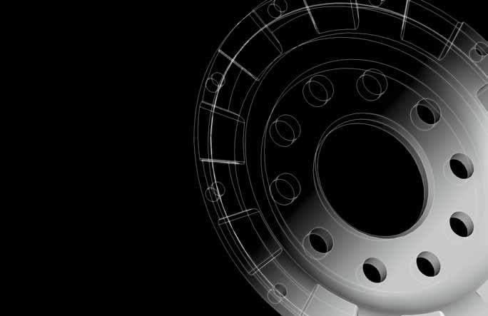
6 Rear iv. Caliper Diagram
7 v. Brake Line Diagram

8 PREPARATION FOR INSTALLATION 1. Be sure that the vehicle is parked on level concrete and the parking brake is on. 2. Place stops in front of and behind rear tires. 3. Consult owner s manual for proper lifting and wheel removal procedures before lifting front of vehicle. 4. Place jack stands under vehicle for added stability. 5. Remove wheel. vi. Installation Procedure - Step 1-5

9 6.Place a brake line clamp on the brake line. This will minimize brake fl uid loss. TOOL NEEDED: Brake Line Clamp Installation Procedure - Step 6

10 7.Using an 11mm wrench, disconnect brake line from caliper. Be aware that brake fluid may leak from line once disconnected. TOOL NEEDED: 11mm Wrench Installation Procedure - Step 7

11 8. Disconnect ABS sensor grommet from mounting bracket by pulling straight up. Installation Procedure - Step 8

12 9. Disconnect brake pad sensor from mounting bracket. Pry tab up gently with small flat head screwdriver, rotate counterclockwise 90 degrees, and lift up. TOOL NEEDED: Small Flat Head Screw Driver Installation Procedure - Step 9


13 10.Clip the section of wire between the brake pad and the plug. Be sure to leave sufficient wire length coming from the plug in order to crimp the wires together. Strip 1/8 of the insulation on the wires and connect them together using a wire crimp as illustrated in picture bellow. It is recommended to protect the connection by applying shrink-wrap around the wire crimp. TOOLS NEEDED: Wire Cutter, Wire Crimp Tool, and a Wire Crimp. CUT HERE Installation Procedure - Step 10

14 11.Place the pad sensor plug in the small opening on the upright. Installation Procedure - Step 11

15 12.With a zip tie included in the kit, secure the plugs placement by zip tying it tightly to the ABS wire that is also running through the upright. Installation Procedure - Step 12

16 13.Using a deep well socket, remove the 17mm bolts on the back side of the caliper and remove caliper. TOOLS NEEDED: 3/8 Ratchet Drive and 17mm Socket Installation Procedure - Step 13


17 14.Remove the rotor. If the rotor seems to be stuck in place, lightly tap rotor with a rubber mallet. TOOL NEEDED: Rubber Mallet Installation Procedure - Step 14

18 15.Remove the backing plate. It is held on by three 10mm bolts. TOOLS NEEDED: 1/4 Ratchet Drive and 10mm Socket Installation Procedure - Step 15

19 16.Install the APR caliper mounting bracket with the fl at side facing the outside of the vehicle and tighten with a 17mm deep well socket. 1 TORQUE SPECIFICATIONS: 1 140ft/lbs TOOLS NEEDED: 3/8 Ratchet Drive, 17mm Socket and a Torque Wrench 1 Installation Procedure - Step 16


20 17.Install the APR rotor for the corresponding side (see picture below) and test for clearance on the backside at the bottom. When checking for clearance, be sure to secure and firmly seat the rotor with a bolt. Occasionally there is flash material from the casting in the area circled in the picture to the left. If it is necessary to remove material, a hand file will be sufficient. Note: There is a left and right side rotor. In order to achieve maximum performance it is recommended that the rotors be installed with the outside end of slots pointed in the wheels direction of rotation. Wheel Rotation Area of Concern Installation Procedure - Step 17

21 18.Remove the two 5mm hex head bolts on the inboard side of the APR caliper. These are securing the brake pad retaining bracket. TOOLS NEEDED: 1/4 Ratchet Drive and 10mm Socket Installation Procedure - Step 18

22 19.Remove the brake pad retaining bracket. Be sure to note orientation for reinstallation. Installation Procedure - Step 19

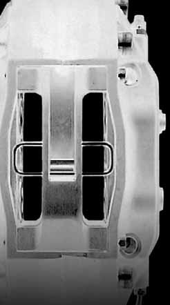
23 20.Install the APR caliper marked for the corresponding side. Be sure the APR logo is facing towards the outside of the vehicle and the bleeder valves are oriented upwards. Note: There is a left and right side caliper and they CANNOT be interchanged. Installation Procedure - Step 20

24 21.Tighten the caliper to the bracket using two 13mm nuts (supplied in brake line package) with a 13mm thin wall socket. 1 1 TORQUE SPECIFICATIONS: 1 45ft/lbs TOOLS NEEDED: 3/8 ratchet, 13mm Socket and a torque wrench. Installation Procedure - Step 21

25 22.Slide a brake pad between caliper and rotor on the inboard side. Be sure that the friction surface is facing the rotor. It is recommended to apply anti squeal spray to the back of the brake pad before installation. Note: Do NOT get any anti squeal spray on the friction surface. Installation Procedure - Step 22

26 23.Slide a brake pad between the caliper and rotor on the outboard side. Be sure that the friction surface is facing the rotor. It is recommended to apply anti squeal spray to the back of the brake pad before installation. Note: Do NOT get any antisqueal spray on the friction surface. Installation Procedure - Step 23


27 24.As illustrated in picture below, reinstall the brake pad retaining bracket in the orientation shown. TOOLS NEEDED: 3/8 ratchet and 13mm Socket Installation Procedure - Step 24


28 25.Install the banjo end of the APR brake line onto the caliper. Keep in mind the final orientation of the brake line as shown in the picture to the left. Note: See Brake Line Diagram for banjo fitting assembly. 1 TORQUE SPECIFICATIONS: 1 11ft/lbs TOOL NEEDED: 14mm Wrench Installation Procedure - Step 25

29 26.Using an 11mm wrench, remove the existing brake line. TOOL NEEDED: 11mm Wrench Installation Procedure - Step 26

30 1 27.Using an 11mm and a 14 mm wrench, install the remaining end of the APR brake line. Check brake line clearance by installing the wheel and turning the steering wheel completely in both directions. Some adjustment may need to be made at the banjo end of the brake line if it interferes with turning. Note: Remove the wheel before bleeding sequence. TORQUE SPECIFICATIONS: 1 11ft/lbs TOOLS NEEDED: 11mm and 14mm Wrench Installation Procedure - Step 27


31 BLEEDING SEQUENCE 1.It is recommended to use a vacuum bleeder when bleeding the braking system. If one is not available, this will be a two-person job. 2.In order to bleed the system properly it must be bled in a specific sequence, listed as follows: Passenger rear, Driver rear, Driver front, Passenger front. 3.During the bleeding sequence you will be replacing your existing brake fluid with new better performing brake fluid. To do so you will need a vacuum pump to remove the existing brake fluid from the reservoir. With the vacuum pump, remove the brake fluid from the reservoir. DO NOT press the brake pedal at this time! It is very important that no air be allowed to enter the hydraulic clutch port. Refi ll the reservoir to a level between the maximum and minimum mark with the new brake fluid. Hydraulic Clutch Port TOOL NEEDED: Vacuum Pump vii. Bleeding Sequence
32 BLEEDING WITHOUT A VACUUM BLEEDER 1. Be sure that the brake reservoir if full. Check this level throughout the sequence. If fluid is needed, replenish the reservoir with the new brake fl uid supplied with the kit. 2. One person will operate the brake pedal throughout the sequence. 3. Press brake pedal slowly three times, not allowing pedal to travel completely to the floor. (Hint: Use something under the pedal to keep the pedal two inches from the floor.) On the third pump, hold pressure to the pedal. 4. Starting with passenger rear, open bleeder screw and release fluid until stream dies. 5. With pressure still applied to the pedal, tighten bleeder screw and repeat steps 1-4 until fl uid flows smoothly with no air. 6. Continue bleeding each brake in the suggested sequence always checking the level in the brake reservoir. Note: On the front brakes, start with the inboard side bleeder screw followed by the outboard. 7. Once the sequence is completed, check the pedal for firmness. If the pedal feels spongy, repeat the bleeding sequence. BLEEDING WITH A VACUUM BLEEDER 1. Be sure that the brake reservoir if full. Check this level throughout the sequence. If fluid is needed, replenish the reservoir with the new brake fluid supplied with the kit. 2. Starting with Passenger rear, attach vacuum bleeder to the bleeder valve and bleed fluid until there is no air in the line. 3. Continue bleeding each brake in the suggested sequence always checking the level in the brake reservoir. Note: On the front brakes, start with the inboard side bleeder screw followed by the outboard. 4. Once sequence is completed, check the pedal for firmness. If the pedal feels spongy, repeat bleeding sequence. Note: Once brakes have been successfully installed, allow 250 miles for brake pads to fully seat. Caution: Under heavy breaking conditions, when the rotors and pads have become extremely hot, it is recommended not to come to a complete stop. If the rotor is not allowed to cool, brake pad material can transfer to the rotor and cause the rotor to feel warped. If you must stop, keep the vehicle slightly in motion so that the brake pad doesn t have time to heat up and stick to the rotor. Bleeding Sequence
33 CLEANING THE ROTOR The majority of brake system problems are due to improper installation and/or break-in of the rotors and pads. By reading and understanding the following, you will avoid the most common causes of poor brake performance and vibration. FAILURE TO READ AND UNDERSTAND THIS MAY CAUSE SERIOUS PERMENANT DAMAGE TO YOUR NEW ROTORS. Your new APR rotors are coated with a water soluble, environmentally friendly rust inhibitor that MUST be cleaned before use. Even though you may not see a change in the rotor color, if the rotor is not rusty, the rust inhibitor is there. Use soap and water, NOT BRAKE CLEANER to wash the rotors. A small piece of Scothbrite works well to scrub with. When cleaned and rinsed properly, the surface of the rotor will immediately show a light rust color, which is normal. Breaking in rotors and pads is critical to the optimum performance of your new brakes. When breaking in new parts, you are not only heat cycling the pads, but depositing a layer of pad material onto the rotor face as well. If not broken in properly, an uneven layer of pad material will be deposited onto the rotor causing vibration. Virtually every instance of a warped rotor is attributed to uneven pad deposition. BEDDING THE BRAKES Typically, a heavy braking street driver will experience approximately 1 to 1.1G s of deceleration. At this rate, ABS will be activated on such equipped vehicles. A moderate braking effort is needed to properly viii. Cleaning and Bedding Procedure break in rotors and pads. A stopping force of approximately 0.8G s, just short of ABS intervention is a general estimate of pedal effort you are trying to achieve. After completing installation, make a series of 10 stops from 60 to 5-10 MPH. At the end of each stop, immediately accelerate to 60 again for the next stop. The exact speed is not critical. Accelerate to approximately 60 and begin the braking cycle. As you approach 5-10 MPH, it is not necessary to watch the speedometer, keep your eyes on the road and approximate your speed at the end of each cycle. DO NOT COME TO A COMPLETE STOP, AS YOU WILL IMPRINT PAD MATERIAL ONTO THE ROTOR, CAUSING A VIBRATION. There are several indicators to look for while breaking in the system. On the 8th or 9th stop, there should be a distinct smell from the brakes. Smoke may be evident after several stops as well. Also on the 8th or 9th stop, some friction materials will experience green fade. This is a slight fading of the brakes. The fade will stabilize, but not completely go away until the brakes have cooled. After the break-in cycle is finished, there will be a blue tint color on the rotor with a light gray film on the rotor face. The blue tint indicates the rotor has reached the proper break in temperature and the gray film is pad material starting to transfer onto the rotor face. If racing or higher performance pads are being used, add four stops from 80 to 5-10mph and if a full race pad, four stops from 100 to 5-10 mph. APR does not endorse speeding on public roads. If going above the legal speed limit, do so in a safe area, away from traffic at your own
34 risk. After the final stop, drive as much as possible without using the brakes to cool off the system. Ideally, the brakes should be allowed to cool to ambient temperature before using again. DO NOT COME TO A COMPLETE STOP WHEN THE SYSTEM IS HOT AND LEAVE YOUR FOOT ON THE PEDAL. PAD MATERIAL WILL IMMEDIATELY TRANSFER TO THE ROTOR CAUSING A VIBRATION. After the first break in cycle shown above, the brakes will still not be operating at their best capacity. A second or third heat cycle is typically necessary before the brakes really start to come in. If you have any questions about rotor and pad break in, or any aspect of your APR brake kit, please contact APR. Cleaning and Bedding Sequence

35 Congratulations, the installation is now complete! We hope you enjoy many miles of service from your new APR brakes. If you ever have any questions, don t hesitate to contact your APR representative.
BI-PIPE INSTALLATION MANUAL. AUDI PERFORMANCE & RACING 1027-B Opelika Road Auburn Alabama 36830
 BI-PIPE INSTALLATION MANUAL i. Disclaimer TABLE OF CONTENTS ii. iii. iv. Tools Needed Parts In the Kit Installation Procedure TABLE OF CONTENTS , LLC does not endorse modification of vehicles for use in
Fitting Instructions VWR Performance Air Filter 2.0 TFSI.
 Fitting Instructions VWR Performance Air Filter 2.0 TFSI VWR Performance Air Filter TFSI Installation Guide Thank you for choosing the VWR Panel Air Filter for your TFSI - developed exclusively by Volkswagen
Installation Instructions Porsche C Carrera 2S Cayman S Front Big Brake Upgrade ST-60 Caliper
 Installation Instructions Porsche 1998-2004 996 C2 2005+ 997 Carrera 2S 2006-2010 Cayman S Front Big Brake Upgrade ST-60 Caliper 98-788-1670-00 05/10/10 1 Porsche Front Big Brake Kit Note: It is important
Installation Instructions. Audi S5, A5, A4 332, 355 & 380mm Front Big Brake Upgrade ST-40 and ST-60 Caliper
 Installation Instructions Audi S5, A5, A4 332, 355 & 380mm Front Big Brake Upgrade ST-40 and ST-60 Caliper 98.114.1680.02 07/23/09 Audi S5, A5, A4 Big Brake Kit Kit Contents Your StopTech Big Brake kit
STāSIS Engineering R8 Brake System
 STāSIS Engineering R8 Brake System Brake Kit Installation Instruction Application Guide SE811-B30-91-00 R8 Brake System Special Tools Required Qty Description 1 10 MM Allen Head Socket 1 M10 Triple Square
Installation Instructions
 Nov 25, 2013 Upper Control Arms Installation Instructions The following instructions are intended for professional installers and are guidelines only. Speedtech Performance assumes NO responsibility for
/14/09. Mitsubishi EVO X. 355mm Front Big Brake Upgrade ST-60 Caliper
 98.625.1670-01 12/14/09 Mitsubishi EVO X 355mm Front Big Brake Upgrade ST-60 Caliper COMPONENT IDENTIFICATION AeroRotor and Hat Assemblies ST-60 Caliper ST-60 Caliper High-Performance Street Pads Caliper
Please Read Instructions Completely Before Starting Your Installation QTY. PART NO. DESCRIPTION
 INSTRUCTIONS 916-31926 Master Cylinder and Pedal Assembly Speedway Motors, Inc. 2015 Master Cylinder and Pedal Assembly Model T Model A, and '32 Fords The master cylinder is suitable for 4-wheel disc or
370 and 390 Mono 6 Brake Kit Installation Guide
 370 and 390 Mono 6 Brake Kit Installation Guide Application Guide Description C7 A6 / A7 390mm Mono6 Brake Kit B8 A4/S4/A5/S5/Q5 390mm Mono 6 Brake Kit C7 A6 / A7 370mm Mono 6 Brake Kit B8 A4/S4/A5/S5/Q5
Mazda RX MX-5 Miata Front Big Brake Upgrade ST-40 Caliper / 2-piece Rotor
 Mazda RX-8 2004+ MX-5 Miata 2006+ Front Big Brake Upgrade ST-40 Caliper / 2-piece Rotor 98-548-1430-00 3/14/16 Front Axle Kit Note: It is important to read and understand this ENTIRE installation manual,
Tools, Equipment and Supplies Needed:
 153-162 DISC BRAKE/DUAL MASTER CYLINDER CONVERSION Please take the time to read the enclosed instructions carefully. If you have any questions, call our Product Assistance personnel for clarifi cation.
Aug 24, 2017 ATS AFX Spindle Installation Instructions
 Aug 24, 2017 ATS AFX Spindle Installation Instructions 1 P a g e The following instructions are intended for professional installers and are guidelines only. Speedtech Performance assumes NO responsibility
SPORT COIL SPRINGS Scion xa & xb Part #19412 INSTALLATION OF HOTCHKIS FRONT COIL SPRINGS
 SPORT COIL SPRINGS 2004+ Scion xa & xb Part #19412 Thank you for your purchase from our new line of Scion xa / xb parts. Please call us at (877) 4NO-ROLL if you have any questions regarding the service
Dec 1, 2017 ATS AFX Spindle Installation Instructions
 Dec 1, 2017 ATS AFX Spindle Installation Instructions 1 P a g e The following instructions are intended for professional installers and are guidelines only. Speedtech Performance assumes NO responsibility
Installation Instructions
 Installation Instructions 98-836-1430-11 01/04/10 Subaru Impreza WRX / STi Front Big Brake Upgrade 328, 332, 355mm Rotors ST40 Front Big Brake Kit for the Subaru WRX / STi Kit Contents (This is a representative
78-88 G Body Rear Trailing Arm Kit
 May 14, 2014 78-88 G Body Rear Trailing Arm Kit Parts in this kit may vary slightly from photo. The following instructions are intended for professional installers and are guidelines only. Speedtech Performance
Installation Instructions For GM SUVs & Trucks
 Installation Instructions For GM SUVs & Trucks 380mm (15 ) Front Big Brake Upgrade 98-182-1480-02 11/17/09 1 pair of ST-45, 4 Piston Calipers sized specifically for GM SUV s & Trucks 1 set of high performance
Installation Instructions BMW E92 M3
 Installation Instructions BMW E92 M3 355mm Rear Big Brake Upgrade ST-40 Caliper 98.160.1471-01 11/17/09 BMW E92 M3 Big Brake Kit Kit Contents Your StopTech Big Brake kit includes the following: 1 pair
Installation Instructions Subaru Impreza WRX 2002+
 Installation Instructions Subaru Impreza WRX 2002+ 328mm Rear Big Brake Upgrade ST-22 Caliper 98-836-1331-03 01/04/10 Subaru Impreza WRX Rear Big Brake Kit (This is a representative photograph. The actual
Installation Instructions Acura TSX
 Installation Instructions 2004+ Acura TSX 328mm Front Big Brake Upgrade ST-40 Caliper 98-059-1430-02 10-01-04 COMPONENT IDENTIFICATION AeroRotor and Hat Assemblies Caliper Brackets High-Performance Street
BMW 135i and 335i Rear Big Brake Upgrade ST-40 Caliper F1.00 1/15/10
 BMW 135i and 335i 2007+ Rear Big Brake Upgrade ST-40 Caliper 98.165.14F1.00 1/15/10 APPLICATION DISCLAIMER Caliper Clearance Most 17 wheels will clear the outer diameter of the caliper for a 328mm or 332mm
Wilwood Brake Kit for Total Performance Spindle
 INSTRUCTIONS 835-140170 Speedway Motors, Inc. May 2011 Wilwood Brake Kit for Total Performance Spindle Note: NOTE: Disc brakes operate in a harsh environment. To prevent bolts from working loose, every
Installation Instructions
 Nov 3, 2017 G-Body Rear Coilover Conversion Kit 1 P a g e Installation Instructions The following instructions are intended for professional installers and are guidelines only. Speedtech Performance assumes
Chicane Coilover Kit For '64 to '72 Chevelle/ A Body. Installation Instructions
 Nov 3, 2017 Chicane Coilover Kit For '64 to '72 Chevelle/ A Body Installation Instructions Actual parts may vary from photo depending on application. 1 P a g e The following instructions are intended for
Chicane Coilover Kit For '70 to '81 Camaro/Firebird
 Nov 25, 2013 Chicane Coilover Kit For '70 to '81 Camaro/Firebird 1 P a g e Installation Instructions The following instructions are intended for professional installers and are guidelines only. Speedtech
1401 / 1402 / 1403 ADJUSTABLE TRAILING ARM MOUNT BRACES INSTALLATION OF HOTCHKIS PERFORMANCE ADJUSTABLE TRAILING ARM MOUNT BRACES
 1401 / 1402 / 1403 ADJUSTABLE TRAILING ARM MOUNT BRACES 1401 78-88 GM A/G-BODY / 1402 68-72 GM A-BODY / 1403 64-67 GM A-BODY Thank you for your purchase. Please call us at (562) 907-7757 if you have any
Installation Manual BMW E39 M5 and 5-Series
 Installation Manual 2000+ BMW E39 M5 and 5-Series Rear Big Brake Upgrade ST-40 Caliper 98-135-1471-04 11/18/09 COMPONENT IDENTIFICATION AeroRotor and Hat Assemblies Caliper Brackets High-Performance Street
Sport Sway Bar Kit (22425) Scion tc
 Scion tc") Sport Sway Bar Kit (22425) Scion tc Thank you for your purchase from our new line of Scion tc parts. Please call us at (877) 4NO - ROLL if you have any questions regarding the service or installation of
Sport Sway Bar Kit (22425) Scion tc Thank you for your purchase from our new line of Scion tc parts. Please call us at (877) 4NO - ROLL if you have any questions regarding the service or installation of
Installation Instructions
 Installation Instructions Subaru Impreza WRX STI 2002-2006 STR-40 Rear Trophy Kit 98-838-1431-00 03/26/09 cl. APPLICATION DISCLAIMER Caliper Clearance Most 17 wheels will clear the outer diameter of the
22427 SWAY BAR SET 2002-UP SUBARU WRX WAGON
 22427 SWAY BAR SET 2002-UP SUBARU WRX WAGON Thank you for your purchase from our line of Subaru WRX parts. Please call us at (877) 4NO-ROLL if you have any questions regarding the service or installation
UPPER TRAILING ARM REMOVAL
 #1204 MUSTANG UPPER TRAILING ARMS Thank you for your purchase. Please call us at (562) 907-7757 if you have any questions regarding your Hotchkis Performance products. Visit us online @ www.hotchkis.net
/17/09
 98.180.1670.04 11/17/09 COMPONENT IDENTIFICATION AeroRotor and Hat Assemblies ST-60 Caliper ST-60 Caliper High-Performance Street Pads Caliper Brackets Stainless Braided Lines and Hardware Big Brake Kit
'64-72 Chevelle/ A Body Rear Coilover Conversion Kit
 Nov 3, 2017 '64-72 Chevelle/ A Body Rear Coilover Conversion Kit Includes instructions for Currie Brand Axles The following instructions are intended for professional installers and are guidelines only.
RACE PPE Manifolds and Up-Pipes
 RACE ONLY High-Flow Exhaust Manifolds with Up-pipes GM DURAMAX 6.6L 2001-2015 DISCLAIMER OF LIABILITY This is a performance product which increases horsepower above factory specifications. Additional horsepower
DISC BRAKE/DUAL MASTER CYLINDER CONVERSION. Tools, Equipment and Supplies Needed:
 Please take the time to read the enclosed instructions carefully. If you have any questions, call our Product Assistance personnel for clarification. It is important to note that these instructions contain
Infiniti G35 Sport Sedan 2007+
 ion s Infiniti G35 Sport Sedan 2007+ 355mm Front Big Brake Upgrade ST-40 Caliper 98.487.1450.01 12/10/09 Infiniti G35 Front Big Brake Kit (This is a representative photograph. The actual components in
Installation Instructions VW Corrado VR Golf GTi VR Jetta VR Passat VR6 Later Model VWs
 Installation Instructions Installation Instructions For 1992-95 VW Corrado VR6 1994-95 Golf GTi VR6 1994+ Jetta VR6 1993-97 Passat VR6 Later Model VWs Front Big Brake Upgrade 98-887-1430-03 01/04/10 VW
Sport Sway Bar Kit (22431 ) Subaru Forester INSTALLATION OF HOTCHKIS FRONT SWAY BAR
 Subaru Forester INSTALLATION OF HOTCHKIS FRONT SWAY BAR") Sport Sway Bar Kit (22431 ) Subaru Forester Thank you for your purchase from our new line of Forester parts. Please call us at (877) 4NO - ROLL if you have any questions regarding the service or installation
Sport Sway Bar Kit (22431 ) Subaru Forester Thank you for your purchase from our new line of Forester parts. Please call us at (877) 4NO - ROLL if you have any questions regarding the service or installation
94-96 Impala SS/ B-Body Rear Coilover Conversion Kit
 January 29, 2014 94-96 Impala SS/ B-Body Rear Coilover Conversion Kit The following instructions are intended for professional installers and are guidelines only. Speedtech Performance assumes NO responsibility
Assembly Instructions
 TOOLS REQUIRED: _(2) 3/4 wrenches _7/16 wrench _3/8 wrench _5/16 allen wrench Display/work stand is for assembly procedure only. May be purchased separately. CONTENTS (PARTS & HARDWARE) _(1) Receiver tube
Installation Instructions
 Nov 25, 2013 Custom Bent Brake Line Kit '67-'69 Camaro and '68-'74 Nova Installation Instructions The following instructions are intended for professional installers and are guidelines only. Speedtech
Anti-roll bar set Chrysler Magnum, Charger, 300C, SRT Dodge Challenger
 Anti-roll bar set 22101 Chrysler Magnum, Charger, 300C, SRT-8 22107 Dodge Challenger Thank you for your purchase from our new line of Chrysler parts. Please call us at (877) 4NO-ROLL if you have any questions
INSTALLATION INSTRUCTIONS
 INSTALLATION INSTRUCTIONS 1301 / 1302 / 1305 / 1306 THANK YOU FOR CHOOSING HOTCHKIS PERFORMANCE PRODUCTS Removal of Stock Lower Trailing Arms 1) Place car on level surface. 2) Support rear of the car on
'64-72 Chevelle/ A Body Rear Coilover Conversion Kit
 February 3, 2014 '64-72 Chevelle/ A Body Rear Coilover Conversion Kit Includes instructions for Currie Brand Axles The following instructions are intended for professional installers and are guidelines
JK BIG BRAKE KIT Part # Part #
 TeraFlex, Inc. 5241 South Commerce Dr. Murray, Utah 84107 Phone/801.288.2585 Fax/801.713.2313 www.teraflex.biz Rev. 12 July 2010 TT PRODUCT INSTALLATION GUIDE JK BIG BRAKE KIT Part # 4303400 Part # 4303420
5) The trailing arm should then pivot smoothly on the chassis. 6) Install the rear bolt. 7) Place one drop of blue Loctite
 The trailing arm should then pivot smoothly on the chassis. 6) Install the rear bolt. 7) Place one drop of blue Loctite") INSTALLATION INSTRUCTIONS 1301 / 1302 / 1305 / 1306 THANK YOU FOR CHOOSING HOTCHKIS PERFORMANCE PRODUCTS Removal of Stock Lower Trailing Arms 1) Place car on level surface. 2) Support rear of the car on
INSTALLATION INSTRUCTIONS 1301 / 1302 / 1305 / 1306 THANK YOU FOR CHOOSING HOTCHKIS PERFORMANCE PRODUCTS Removal of Stock Lower Trailing Arms 1) Place car on level surface. 2) Support rear of the car on
MOVE ON TO THE REAR BAR INSTALLATION
 22410 STREET SWAY BAR SET 2001-UP LEXUS IS300 Thank you for your purchase from our line of Lexus parts. Please call us at (877) 4NO-ROLL if you have any questions regarding the service or installation
WOLF BRAND SCOOTERS WARRANTY 2018
 WOLF BRAND SCOOTERS WARRANTY 2018 Two (2) year or ten thousand (10,000) mile, whichever comes first, limited warranty. Two (2) year limited battery warranty. One (1) year for internal engine and transmission
STC 2W Series Solenoid Valves
 STC 2W160-500 Series Solenoid Valves 2W160-500 Series Solenoid Valve Specifications Valve Model 2W160-3/8 2W160-1/2 2W200-3/4 2W250-1 2W350-1 1/4 2W400-1 1/2 2W500-2 Valve Type Action 2 Way, Normally Closed
Installation Instructions. Acura TSX mm Rear Big Brake Upgrade ST-22/ST-10 Calipers
 Installation Instructions Acura TSX 2004+ 328mm Rear Big Brake Upgrade ST-22/ST-10 Calipers 98-059-1331-03 02-22-05 Acura TSX Rear Big Brake Kit Your StopTech Big Brake kit includes the following: ST-22
STC 2L Series Solenoid Valves
 STC 2L170-500 Series Solenoid Valves 2L170-500 Series Solenoid Valve Specifications Valve Model 2L170-3/8 2L170-1/2 2L170-3/4 2L200-1 2L300-1 1/2 2L500-2 Valve Type Action 2 Way, Normally Closed (NC) Pilot
INSTALLATION OF HOTCHKIS FRONT STABILIZER BAR
 22441 FRONT AND REAR SPORT SWAY BAR SET Infiniti G37/S Coupe & G35/S Sedan Thank you for your purchase from our Hotchkis line of suspension parts. Please call us at (877) 4NO-ROLL if you have any questions
25405 COMPETITION END LINK KIT 2002-UP ACURA RSX, 2004 Subaru STi INSTALLATION OF HOTCHKIS FRONT ENDLINKS
 25405 COMPETITION END LINK KIT 2002-UP ACURA RSX, 2004 Subaru STi Thank you for your purchase from our line of competition parts. Please call us at (877) 4NO-ROLL if you have any questions regarding the
22421 SPORT SWAY BAR SET TOYOTA COROLLA
 22421 SPORT SWAY BAR SET 98-01 TOYOTA COROLLA Thank you for your purchase from our line of Corolla parts. Please call us at (877) 4NO-ROLL if you have any questions regarding the service or installation
V-Twin Forward Control Installation Instructions
 V-Twin Forward Control Installation Instructions Thank you for a choosing a Supreme Legends USA product. Supreme Legends forward controls are designed to add style and performance to your bike. Our extended
INSTALLATION INSTRUCTIONS FOR M.O.R.E. SHACKLE REVERSAL SYSTEM (S.R.S. ) PART # THIS SYSTEM FITS Jeep CJ-5, CJ-7, CJ-8 VEHICLES.
 PART # THIS SYSTEM FITS Jeep CJ-5, CJ-7, CJ-8 VEHICLES.") INSTALLATION INSTRUCTIONS FOR M.O.R.E. SHACKLE REVERSAL SYSTEM (S.R.S. ) PART # 7686-6 THIS SYSTEM FITS 1976-1986 Jeep CJ-5, CJ-7, CJ-8 VEHICLES. Please read all instructions carefully (including terms-policies)
INSTALLATION INSTRUCTIONS FOR M.O.R.E. SHACKLE REVERSAL SYSTEM (S.R.S. ) PART # 7686-6 THIS SYSTEM FITS 1976-1986 Jeep CJ-5, CJ-7, CJ-8 VEHICLES. Please read all instructions carefully (including terms-policies)
2006 SHOCK TOWER BRACE 93-UP F-BODY CAMARO/FIREBIRD
 2006 SHOCK TOWER BRACE 93-UP F-BODY CAMARO/FIREBIRD Thank you for your purchase of this Hotchkis Performance product. Please call us at (800) 4NO-ROLL if you have any questions regarding this product.
Anti-Roll Bar Set # 2279, Cadillac CTS V6 & CTS-V
 Anti-Roll Bar Set # 2279, 2280 2003+ Cadillac CTS V6 & CTS-V Thank you for your purchase from our new line of CTS parts. Please call us at (877) 4NO-ROLL if you have any questions regarding the service
1313 LOWER TRAILING ARMS CHEVROLET B-BODY
 1313 LOWER TRAILING ARMS 59-64 CHEVROLET B-BODY Thank you for your purchase from our line of classic Chevrolet B-body suspension parts.. Please call us at (877) 4NO-ROLL if you have any questions regarding
P/N# Performance Lowering Springs Installation Instructions
 P/N# 19391 Performance Lowering Springs Installation Instructions Thank you for your purchase of this Hotchkis Performance product. Your Lowering Spring set was designed with the performance and durability
BMW E46 M3 SPORT SWAY BAR SET # 22826
 BMW E46 M3 SPORT SWAY BAR SET # 22826 Thank you for your purchase from our new line of BMW E46 parts. Please call us at (877) 4NO - ROLL if you have any questions regarding the service or installation
7.3L POWERSTROKE BANJO BOLT KIT Fits L Powerstroke Diesel. Installation Guide
 7.3L POWERSTROKE BANJO BOLT KIT Fits 94-03 7.3L Powerstroke Diesel Installation Guide INSPECT CONTENTS OF THIS KIT THOROUGHLY BEFORE STARTING THE INSTALLATION PROCESS! IF YOU FIND A PROBLEM WITH YOUR PACKAGE:
Anti-roll bar set (pn 2278) Pontiac GTO
 Pontiac GTO") Anti-roll bar set (pn 2278) Pontiac GTO Thank you for your purchase from our new line of GTO parts. Please call us at (877) 4NO-ROLL if you have any questions regarding the service or installation of your
Anti-roll bar set (pn 2278) Pontiac GTO Thank you for your purchase from our new line of GTO parts. Please call us at (877) 4NO-ROLL if you have any questions regarding the service or installation of your
Sport Sway Bar Kit VW MKV & MKVI Jetta, GTI, GLI Audi A3
 Sport Sway Bar Kit 22833 06-09 VW MKV & MKVI Jetta, GTI, GLI 06-07 Audi A3 Thank you for your purchase from our new line of Audi/VW parts. Please call us at 877-4NO - ROLL if you have any questions regarding
14366, Adjustable Strut Rods Chrysler A-Body Chrysler B-Body Chrysler E-Body
 14366, 14385 Adjustable Strut Rods 67-76 Chrysler A-Body 1966-1970 Chrysler B-Body 1970-1974 Chrysler E-Body Thank you for your purchase from our new line of B & E-Body parts. Please call us at (877) 4NO
INSTALLATION INSTRUCTIONS
 INSTALLATION INSTRUCTIONS BIG ROTOR / CALIPER RELOCATION FRONT KITS SUM-BK1422, BK1423, BK1424 1999-2006 GM 1/2 Ton Trucks & SUVs Thank you for choosing SUMMIT RACING for your braking needs. Pleases take
TactAir 4-Stage PCP Hand Pump. Operation Manual
 TactAir 4-Stage PCP Hand Pump Operation Manual INTRODUCTION Thank you for choosing the TactAir 4-Stage PCP Hand Pump! Always exercise caution when operating this pump. It will allow you to fill your PCP
Feb 22, 2018 '67-69 Camaro & '68-74 Nova Bumpsteer Adjustment Kit
 Feb 22, 2018 '67-69 Camaro & '68-74 Nova Bumpsteer Adjustment Kit 10552 The following instructions are intended for professional installers. Speedtech Performance assumes NO responsibility for the installation
STC 2DS Series Anti-Hammering Slow Closing Pilot Solenoid Valves
 STC 2DS500-2000 Series Anti-Hammering Slow Closing Pilot Solenoid Valves 2DS500-2000 Series Solenoid Valve Specifications Valve Model 2DS400F 2DS500F 2DS650F 2DS800F 2DS1000F 2DS1250F 2DS1500F 2DS2000F
Forbidden Diesel Performance Ford 6.7L Powerstroke EGR Delete Instructions 6.7L EGR DELETE BY FORBIDDEN DIESEL PERFORMANCE. Page 1
 6.7L EGR DELETE BY FORBIDDEN DIESEL PERFORMANCE Page 1 WARNING REGARDING EMISSIONS LAWS Not legal for sale or use on pollution-controlled motor vehicles anywhere in the United States. Legal ONLY for off-road
Toll Free C5 & C4 Brake Bracket Installation Instructions
 Toll Free -888-467-65 www.speedtech-performance.com C5 & C4 Brake Bracket Installation Instructions Installation Instructions: Disclaimer All parts should be installed by a certified mechanic if you choose
Stainless Steel Pilot Piston Solenoid Valve 2MS Series for High Temperature & High Pressure
 Stainless Steel Pilot Piston Solenoid Valve 2MS Series for High Temperature & High Pressure S T C TM To Order, Please Specify: 1) Model No., 2) Voltage 2 Way, NC Pilot Piston Stainless Steel Part No. Voltage
INSTALLATION INSTRUCTIONS
 INSTALLATION INSTRUCTIONS BIG ROTOR / CALIPER RELOCATION REAR KIT SUM-BK1423 1999-2009 GM 1/2 Ton Trucks & SUVs Thank you for choosing SUMMIT RACING for your braking needs. Pleases take the time to read
Rear Leaf Spring Kit 24366, Chrysler B-body, Chrysler E-Body
 P Rear Leaf Spring Kit 24366, 24367 66-70 Chrysler B-body, 70-74 Chrysler E-Body Thank you for your purchase from our new line of Mopar parts. Please call us at 877-4NO - ROLL if you have any questions
Installation Guide: Front Brake Pad
 Installation Guide: Front Brake Pad Ninety percent of the brake pad changes you make during the life of your vehicle will be to the front brakes because they do 60% to 70% of the braking. On most cars,
Sport Coil Springs Dodge Magnum, Chrysler 300C Dodge Challenger SRT Dodge Challenger R/T
 Sport Coil Springs 19101 - Dodge Magnum, Chrysler 300C 19107 - Dodge Challenger SRT-8 19108 - Dodge Challenger R/T Thank you for your purchase from our new line of Magnum/300C parts. Please call us at
STC 2P025 Series Solenoid Valve
 STC 2P025 Series Solenoid Valve 2P025 Series Solenoid Valve Specifications Valve Model Valve Type Action Cv (Orifice) Operating Pressure Operating Temperature 2P025 2 Way, Normally Closed (NC) Direct Acting
Tubular Lower A-Arms GM A-Body Tubular Lower A-Arms GM F-Body
 1104 - Tubular Lower A-Arms 64-72 GM A-Body 1108 - Tubular Lower A-Arms 70-81 GM F-Body Tubular Lower A-Arms: Thank you for your purchase from our new line of A-Body parts. Please call us at (877) 4NO
Installation Instructions
 Mar 13, 2018 1955-1957 Chevy Smooth Firewall Part number 81511 Installation Instructions The following instructions are intended for professional installers and are guidelines only. Speedtech Performance
INSTALLATION INSTRUCTIONS FOR PLEASE READ AND UNDERSTAND TERMS/POLICIES BEFORE YOU INSTALL THIS SYSTEM
 MOUNTAIN OFF ROAD ENTERPRISES. LLC. P.O. BOX 690 DELTA, COLORADO 81416 970-625-0500 E-mail: info@mountainoffroad.com www.mountainoffroad.com INSTALLATION INSTRUCTIONS FOR 8795-2 PLEASE READ AND UNDERSTAND
6032 Jacksboro Highway, #100 Fort Worth, Tx MADE IN THE U.S.A.
 6032 Jacksboro Highway, #100 Fort Worth, Tx 76135 817-306-2444 888-842-6572 I N S T A L L A T I O N I N S T R U C T I O N S D O D G E 9 8. 5-0 2 MADE IN THE U.S.A. w w w. q u a d z i l l a p o w e r. c
2015 & 2018 Fender Brace Installation Instructions
 2015 & 2018 Fender Brace Installation Instructions Thank you for your purchase of this Hotchkis Performance product. Your Fender Brace set was designed with the performance and durability you ve come to
2236 Sway Bar Installation Instructions
 2236 Sway Bar Installation Instructions Thank you for your purchase of this Hotchkis Performance product. Your stabilizer bar set was designed with the performance and durability you ve come to expect
1109 Tubular Lower A-Arms Camaro/Firebird
 1109 Tubular Lower A-Arms 67-69 Camaro/Firebird Tubular Lower A-Arms: Thank you for your purchase from our new line of F-Body parts. Please call us at (877) 4NO - ROLL if you have any questions regarding
PowerMax Diesel Upgrade For Cummins Engines
 PowerMax Diesel Upgrade For Cummins Engines 00.5-007.5 Dodge Ram With Cummins 5.9L Item 3 4 5 6 7 8 9 0 3 4 5 6 7 8 Parts List Description Turbocharger Ancillary kit 773069- (includes) Installation Instructions
Gold Operator Manual
 Gold Operator Manual Call ProMow for ALL Service Needs Toll Free: 1-877-477-6669 Dear Valued Customer. Let me take this opportunity to congratulate you on your purchase of a ProMow Reel Mower System. You
2V1-3V1 SERIES SOLENOID VALVE
 2V1-3V1 SERIES SOLENOID VALVE Valve Model 2V1 3V1 Port & Mounting Body Ported, Stacking Action & Motion Solenoid, Direct Acting, 2 Way Response Time
Rear Suspension System C-10 Pickup Truck
 Rear Suspension System 18390 67-72 C-10 Pickup Truck Thank you for your purchase from our new line of Chevy parts. Please call us at 877-4NO - ROLL if you have any questions regarding the service or installation
Camaro / Firebird. Please read the following key points before installing this kit.
 Please read the following key points before installing this kit. 1 Before performing the subframe connector installation, the vehicle must be completely assembled with all body and component parts installed
JK Big Brake Kit. Important Notes: Tools needed: This installation guide Basic mechanics tool set
 1 JK Big Brake Kit www.teraflex.com Kit #000 Standard Rotors Kit #020 Slotted Rotors Important Notes: Prior to beginning this or any installation read these instructions to familiarize yourself with the
Dual Phase Extraction Inlet. Patent No Installation Manual. P/N Rev
 Patent No. 6520259 Installation Manual P/N 95232 Rev 6-16-11 Table of Contents ing Extraction Inlets track changing water levels to maintain optimum performance 1.Component Identification Page 1 2. How
INSTALLATION GUIDE: EGR Delete Kit Ford 6.7L Powerstroke`
 INSTALLATION GUIDE: EGR Delete Kit 20 203 Ford 6.7L Powerstroke` ! Not legal for sale or use on pollution-controlled motor vehicles anywhere in the United States. Legal ONLY for off-road competition racing
INSTALLATION INSTRUCTIONS
 INSTALLATION INSTRUCTIONS REAR DISC BRAKE CONVERSION KIT A125-3 1965-72 GM A-BODY 10 & 12 BOLT AXLES Thank you for choosing STAINLESS STEEL BRAKES CORPORATION for your braking needs. Pleases take the time
Installation Instructions
 Installation Instructions Rear Disc Brake Conversion Kit Item # RC4001, RC4001X Applications: Mopar 7.25, 8.25, 9.25 Axles Thank you for choosing Leed Brakes for your automotive product needs. Before you
REAR SWAY BAR 2207R GM CAMARO/FIREBIRD
 REAR SWAY BAR 2207R 67-69 GM CAMARO/FIREBIRD Thank you for your purchase of this Hotchkis Performance product. Your stabilizer bar set was designed with the performance and durability you ve come to expect
INSTALLATION INSTRUCTIONS PERFORMANCE AT THE WHEELS KIT W125
 INSTALLATION INSTRUCTIONS PERFORMANCE AT THE WHEELS KIT W125 1968-81 CAMARO & FIREBIRD 10 & 12 BOLT W/"C" CLIPS Thank you for choosing STAINLESS STEEL BRAKES CORPORATION for your braking needs. Pleases
3V SERIES SOLENOID VALVE
 3V110-410 SERIES SOLENOID VALVE Valve Model 3V110-1/8 3V210-1/4 3V310-3/8 3V410-1/2 Port & Mounting Action & Motion Operating Pressure Body Ported Air Pilot, Spool Design, Response Time
INSTALLATION, OPERATION & MAINTENANCE MANUAL
 INSTALLATION, OPERATION & MAINTENANCE MANUAL MODEL: ROT-4500 4,500 LB CAPACITY AUTOMOTIVE ROTISSERIE FOLLOW THIS MANUAL CAREFULLY TO ENSURE THE EQUIPMENT WILL FUNCTION CORRECTLY AND PROVIDE MANY YEARS
Please visit for the latest version of these installation instructions.
 Please visit www.blueox.com for the latest version of these installation instructions. BX2409 2009-18 Dodge Ram 1500 Sport/ST/Laramie Limited Please read BOTH these and the General Information sheet prior
LEXUS IS 250 Front Performance Brake Kit Section I - Installation Preparation
 LEXUS IS 250 Front 2006- Performance Brake Kit Section I - Installation Preparation Part Number: PTR09-53080 Kit Contents Item # Quantity Reqd. Description 1 1 Brake Rotor, LH Front 2 1 Brake Rotor, RH