Emergency Generator Replacement Roseway Hospital
|
|
|
- Martin Henderson
- 5 years ago
- Views:
Transcription
1 Emergency Generator Replacement Roseway Hospital Document Number: NSHA-WZ-001 A D D E N D U M #4 September 17, 2015 The Tender Documents, including Addenda, shall be amended and new clauses and specifications added and become part of the Contract Documents as follows: 1. QUESTION: I would like to request approval for Madsen Power Systems for the supply of the generator for the Roseway Hospital Generator Replacement project. The MPS0600DOM complies with the cooling air and combustion air limits as listed in the technical specification. RESPONSE: The generating set will be acceptable if the supplier meets all the specification requirements including meeting or exceeding the 1633 skva. The radiator cooling air combined with the combustion air must be below 30,000 CFM. The confirmation from the supplier regarding cooling air and starting kva is acceptable for bidding purposes, however should Madsen end up being the proposed generator we will require confirmation of both starting kva and air requirements from the manufacture by way of cutsheet or the manufacturer must sign a letter of confirmation indicating the proposed generator meets all specifications including the above prior to the award of the tender. - End of Addendum # 4-
2 Emergency Generator Replacement Roseway Hospital Document Number: NSHA-WZ-001 A D D E N D U M #3 September 15, 2015 The Tender Documents, including Addenda, shall be amended and new clauses and specifications added and become part of the Contract Documents as follows: 1. STATEMENT: Attached is addendum #3 from the consultants. 2. QUESTION: Request for an additional site visit for demolition subs to review the scope. We did attend the mandatory site visit. RESPONSE: No, due to timing and availability, this cannot be considered. 3. QUESTION: I would like to request approval for General Electric for the automatic transfer switch as an acceptable alternate. RESPONSE: GE Zenith bypass-isolation transfer switch is an acceptable alternate. See attached spec sheets. 4. QUESTION: Per addendum # 2. Re: Section Acceptable Manufacturer. Can you add MTU Onsite Energy (Wajax Power Systems) to the list as per attachments sent. Here are the spec sheets for the generator we will use to meet the required spec. Please add us (MTU Onsite Energy) as an accepted Manufacturer?
3 RESPONSE: The Marathon (MTU On site Energy) generating set is over sized and is not considered an approved equal. - End of Addendum # 3-
4 Roseway Hospital Addendum No. 3 Page 1 Emergency Generator Replacement Shelburne, Nova Scotia This Addendum forms part of the Contract Documents and all relevant terms and conditions of the Contract Documents shall apply in all respects to this Addendum and shall apply as though this Addendum had been incorporated into and formed part of the original document. Insert the Addendum behind cover page of the Contract Documents. SPECIFICATIONS 1. Section Summary of Work.1 Ref. 1.1 Work Covered by Contract Documents:.1 Add para to read as follows:.4 Sprinkler:.1 Add sprinkler head as indicated on drawings. Provide all pipe, fittings as required. 2. Section Facility Fuel Oil Piping.1 Add para. 3.7 to read as follows: 3.7 Painting.1 All exterior piping to be painted with 2 coats marine grade epoxy; colour to match tank. 3. Section Louvres, Intakes and Vents.1 Ref. 2.1 Fixed Louvres Aluminum:.1 Revise para to read as follows:.9 Provide 2 thick factory-mounted blank-off panels where indicated. Sizes of panels on drawings are approximate. Determine exact sizes.
5 Roseway Hospital Addendum No. 3 Page 2 Emergency Generator Replacement Shelburne, Nova Scotia 4. Section Common Work Results for Electrical.1 Ref Temporary Generators:.1 Add para to read as follows:.4 Proposed Electrical Sequence of Providing Temporary Power:.1 Step 1:.1 Provide weatherproof 750 kva, 600 V temporary generator on site complete with 800 A main breaker..2 Provide 800 A, 600 V temporary power panel TPP complete with 250 A 3 pole, 400 A 3 pole and 600 A 3 pole breakers in generator enclosure or within limits of construction. Connect temporary cabling from temporary generator to temporary panel..3 Provide 260 A, 600 V temporary automatic transfer switch ATS-T1 complete with bypass in generator enclosure or within limits of construction. Connect temporary cabling from 250 A 3 pole breaker in temporary panel to transfer switch ATS-T1 (emergency power)..4 Disconnect existing feeders between transformer T-EPP and panel NPP. Run temporary feeders from panel NPP to temporary transfer switch ATS-T1 (normal power). Run temporary feeders from temporary transfer switch ATS-T1 (load power) to primary side of transformer T-EPP..5 Break into existing fire alarm circuit from existing 208 V generator and make connection to temporary generator..2 Step 2:.1 Remove 208 V generator, transfer switch, cabling, conduits, and associated equipment..3 Step 3:.1 Disconnect existing feeder cable from 400 A breaker in generator room feeding Roseway Manor ATS. Connect
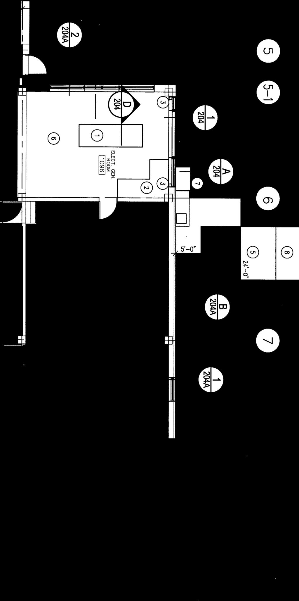
6 Roseway Hospital Addendum No. 3 Page 3 Emergency Generator Replacement Shelburne, Nova Scotia temporary cabling from 400 A temporary panel TPP to existing Roseway Manor feeder cable. Install temporary junction box high on wall sized to suit..2 Disconnect existing feeder cable from 600 A breaker in generator room feeding ATS #1 (emergency power) located in generator room. Connect temporary cabling from 600 A temporary panel TPP to ATS #1 (emergency power)..4 Step 4:.1 Remove 600 V generator, cabling, conduits and associated equipment. 5. Section Aboveground Fuel Storage Tanks.1 Ref. para. 2.1 Tanks: Aboveground, Double-Wall Fuel Storage:.1 Add para to read as follows:.4 Outside dimension of tank shall be as indicated on drawings. DRAWINGS 1. Drawing 201 Partial Floor Plan Demolition.1 Revise Boiler Room wall opening location..2 Add demolition of wall along Grid Drawing 202 Partial Floor Plan New.1 Revise concrete support pads. 3. Drawing 203 Elevations Demolition and New.1 Revise chimney supports. 4. Drawing 203A Elevations Demolition and New at Ambulance Bay.1 Add Drawing 203A Elevations Demolition and New at Ambulance Bay.
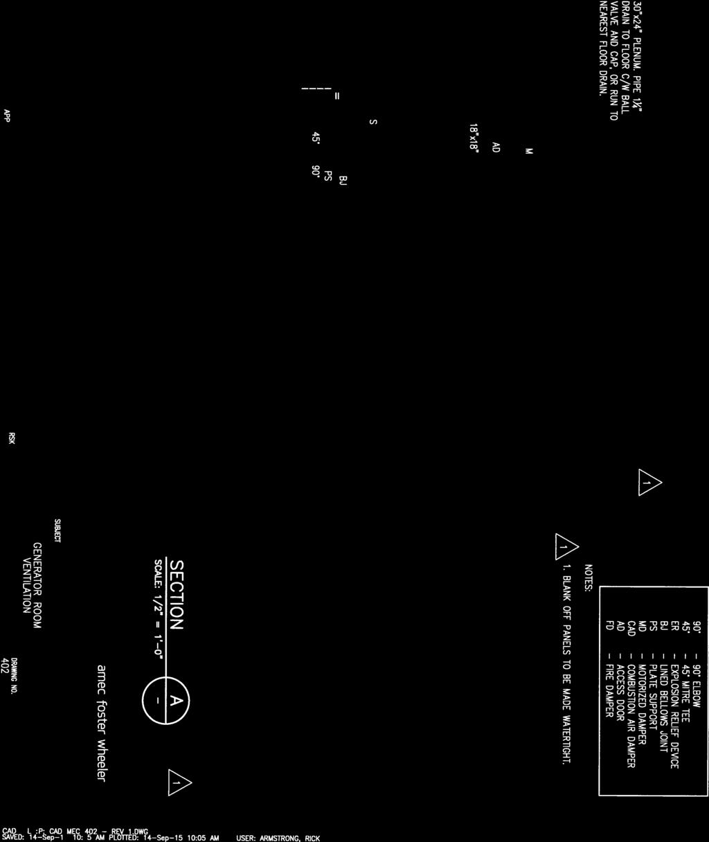
7 Roseway Hospital Addendum No. 3 Page 4 Emergency Generator Replacement Shelburne, Nova Scotia 5. Drawing 204 Wall Sections and Misc. Details.1 Revise Details A, B..2 Delete Detail C. 6. Drawing 204A Details.1 Add Drawing 204A Details. 7. Drawing 205 Miscellaneous Details.1 General revisions on Drawing Drawing 206 Structural Details.1 Revise chimney supports..2 Revise scale from 1½ = Drawing 402 Generator Room Ventilation.1 Revise size of Louvers L-1 and L-2..2 Revise layout and notes for 10 dia. Stack upstream of silencer..3 Add notes 2 and 3..4 Remove combustion air damper from Section A..5 Add combustion air Louver L-5 and fire damper..6 Provide new Silencer SL-3 at Louver L Drawing 403 Boiler Room Ventilation Plan.1 Revise size of Louvers L-1 and L-2..2 Relocate intake Louver L-4, Supply Fan SF-1 and all associated ductwork to exterior wall at grid line A..3 Revise size and location of Louver L-5..4 Revise location of tank alarm control panel. 11. Drawing 404 Fuel Oil Piping and Storage Plan.1 Revise size of Louvers L-1 and L-2..2 Revise size and layout for exterior 4000 gallon tank..3 Revise exterior fuel oil piping layout to from tank to chimney..4 Add Louver L-5..5 Revise location of tank alarm control panel.
8 Roseway Hospital Addendum No. 3 Page 5 Emergency Generator Replacement Shelburne, Nova Scotia 12. Drawing 405 Elevations.1 Revise orientation of chimney and associated components on Elevation 2..2 Revise fuel oil piping on Elevation 2..3 Indicate section cut A on Elevation 2..4 Identify mechanical room floor elevation on Elevations 1 and 2..5 Revise demolition notes on Elevation Drawing 405A Section.1 Add Drawing 405A Section. 14. Drawing 408 BAS Control Schematics Sheet 1 of 2.1 Revise gen status control point on Generator Control Schematic #2..2 Add note describing gen status control point..3 Add Control Schematic 5, Fuel Filtration Unit Generator Run Shut-down. 15. Drawing 410 Mechanical Schedules.1 Revise size of Louvers L-1 and L-2 noted on Louver Schedule..2 Revise size of Silencers Sl-1 and SL-2 noted on Silencer Schedule..3 Add remarks and active size to Louver Schedule..4 Add Silencer SL-3 to Silencer Schedule..5 Add Louver L-5 to Louver Schedule. 16. Drawing 502A Temporary Generator Single Line Diagram.1 Add Drawing 502A Temporary Generator Single Line Diagram. 17. Drawing 503 Deconstruction Plan.1 Relocate existing wall pack to facilitate installation of louver.
9 Roseway Hospital Addendum No. 3 Page 6 Emergency Generator Replacement Shelburne, Nova Scotia 18. Drawing 505 Power Plan.1 New location of existing wall pack..2 Revise location of receptacle on grid line Revise location of Supply Fan SF Drawing 507 Lighting Plan.1 Install bracket to ensure emergency lighting heads extend past louver. END
10

11


12

13
14

15

16


17


18


19

20


21

22

23


24


25
26
27

28

29 GE Digital Energy Power Quality Zenith ZTS Series Low-Voltage Automatic and Manual Transfer Switches

30 Since its introduction, GE s Zenith ZTS Series of transfer switches has become a hallmark of quality and performance. Reliability resulting from superior design and heavy duty construction has made the ZTS the industry standard for critical installations. Our emphasis on research and development, design improvements, materials, manufacturing methods, quality assurance and service yields products that have been proven in hundreds of thousands of applications. Subsequent to the first ZTS units installed, our engineering staff has been dedicated to the improvement and expansion of our line. Today, GE offers the widest selection of transfer switch products worldwide. ZTS Automatic Transfer Switches Amps ZTSD Delayed Transition Transfer Switches Amps ZTSCT Closed Transition Transfer Switches Amps ZBTS Automatic Transition Bypass Switches Amps ZBTSD Delayed Transition Bypass Switches Amps ZBTSCT Closed Transition Bypass Switches Amps All ZTS products meet or exceed industry requirements allowing specification and installation confidence. UL 1008 listed through 480 VAC CSA C22.2 No. 178 listed through 600 VAC IEC listed through 480 VAC Codes and Standards NFPA 70, 99, 101, 110 IEEE 446, 241, 602 NEC 517, 700, 701, 702 NEMA ICS-10 Controls tested in accordance with: IEEE 472 (ANSI C37.90A) EN55022 Class B (CISPR 22) (Exceeds EN55011 & MILSTD 461 Class 3) EN Class B (Level 4) EN (ENV50140) 10 v/m EN EN , IEEE C62.41 (1.2 X 50μs, 0.5 to 4 kv) EN (ENV50141) EN Equipment (Controls and Power Section) Seismic Test Qualified to: IBC-2006 IEEE Enclosures meet the requirements of: UL 508, 50 ANSI C33.76 ICS 6 NEMA 250 Quality System ISO 9001 Registered Specification Assistance GE offers a complete range of product guide specifications to help you determine your needs. For more information, please consult your local GE representative, our factory or our website at PB-5066 Page 2
31 Zenith ZTS Series Automatic Transfer Switches The Zenith ZTS Series is the building block of our transfer switch product line. This ruggedly built power contactor family of switches has been specifically designed for transfer switch duty with dependability, versatility and user friendliness of prime concern. ZTS switches are available in open type construction for switchboard installation or nema enclosed to the customer s specifications. The power panel components, consisting of power switching contacts, drive mechanism and terminal lugs, are mounted on a specially formed panel. Logic devices including microprocessor control auxiliary time delays and special accessory equipment are assembled on the door for ease of maintenance and separation from the power section. They are connected with a numbered wiring harness equipped with a disconnect plug that allows isolation of the control panel for maintenance. ZTS Series Method of Operation When Source 1 voltage fails or drops to a predetermined point (usually 80% of nominal), if required, a circuit is closed to start the engine generator set. When Source 2 reaches 90% of rated voltage and 95% of rated frequency, the drive solenoid is energized through the Source 2 coil control relay, causing the main contacts to disconnect the load from Source 1 and connect it to Source 2. After the drive solenoid has completed its electrical stroke and is seated, the Source 2 coil control relay opens to disconnect it. The transfer switch is now mechanically locked in the Source 2 position. When Source 1 voltage is restored to a predetermined point (usually 90% of nominal), the control voltage sensing energizes. The Source 1 side coil relay closes, and after the drive solenoid has completed its electrical stroke and is seated, the coil control relay opens to disconnect it. The transfer switch is now mechanically locked in the Source 1 position. Drive Mechanism All Zenith ZTS switches employ the simple over-center principle to achieve a mechanically locked position in either Source 1 or Source 2 and GE s high speed drive assures contact transfer in 100ms or less. High contact pressure and positive mechanical lock allow for high withstand and closing ratings, far exceeding UL requirements. All ZTS units are listed with UL umbrella (any) breaker, coordinated breaker and current limiting fuse ratings. Neutral Switching The Zenith ZTS Series is available in true four pole designs for multi-source power systems that require neutral switching. The neutral contact is on the same shaft as the associated main contacts. This ensures positive operation, and avoids any possibility that the neutral contact will fail to open or close, as is possible when the neutral pole is an add-on accessory. The neutral contacts are identical to the main contacts, having the same current carrying and high withstand/closing ratings as the mains. They are designed to break last and make first to reduce the possibility of transients while switching the neutral. Safe Manual Operation The ZTS manual operator consists of a large, easy-to-use handle that fits securely for manual operation during installation and maintenance or in an emergency. The ZTS may be provided with an operator inhibit switch to disconnect the electrical drive prior to maintenance. Fully enclosed wrap-around arc covers shield the main contacts and mechanical components, preventing operator exposure during manual operation. Transferring Large Motor or Highly Inductive Loads Some loads, especially large motors, receive severe mechanical stress if power is transferred out of phase while the motor is still rotating. Also, back EMF generated by a motor may result in excess currents that can blow fuses or trip circuit breakers. GE offers four solutions to these problems: Universal Motor Disconnect (UMD): This load control disconnects a large motor via its control circuit for an adjustable period of time prior to transfer in either direction. For switching multiple motors, GE s Accessory A62 disconnects the motors prior to transfer and brings them back on line sequentially. Accessory R50: This is an in-phase monitor that compares the phase angle between both sources of power and prevents transfer until the two are approximately in phase (within a selfadjusting range). GE s high speed transfer action, coupled with the MX series microprocessor control logic, ensure closures at or near zero degree phase difference. Series ZTSD: GE offers delayed transition switching on transfer switches rated 40 amperes and above the GE Zenith ZTSD Series. This programmed center-off position allows for the full decay of rotating motors or transformer fields. It can also be used for load shedding of selected circuits or other applications which require a means to disconnect the load from either source. Major UPS system manufacturers recommend delayed transition switches for proper restart sequencing of their systems. Series ZTSCT: GE s Zenith series of closed transition switches combine ZTSD operation during a source failure with a highly engineered control system that allows momentary paralleling (100 ms) of two acceptable sources, thereby limiting the impact of transfer on the load. Electrical Ratings Ratings 40 to 4000 amperes 2, 3 or 4 Poles Open type, NEMA 1, 3R, 4, 4X and 12 Available to 600 VAC, 50 or 60 Hz Suitable for emergency and standby applications on all classes of load, 100% tungsten rated through 400 amps UL 1008 listed at 480 VAC CSA C22.2 No. 178 certified at 600 VAC IEC listed at 480 VAC Performance Features Contact transfer speed less than 100 milliseconds High close-in and withstand capability Temperature rise test per UL 1008 conducted after overload and endurance tests - exceeds UL requirements Available in ZTS (utility-generator), ZTSU (utility-utility), ZTSG (generator-generator) and ZTSM (manual) configurations Design and Construction Features Double throw, interlocked operation Electrically operated, mechanically held by a simple, over-center mechanism Segmented silver tungsten alloy contacts with separate arcing contacts on 225 amp and above Arc quenching grids, enclosed arc chambers, and wide contact air gap for superior source-to-source isolation on all units Control circuit disconnect plug and drive inhibit switch for safe maintenance Components accessible for inspection and maintenance without removal of the switch or power conductors Mechanical indicator and contact chamber cover designed for inspection, safety and position designation Page 3 PB-5066

32 MX250 Series Microprocessor Controller Enhanced Display and Settings LEDs are used in a recognizable line configuration for continuous monitoring of switch position. The LCD display shows source availability, exercise time delay operation and system source condition. A simplified adjustment is featured for voltage, frequency and time delay settings. LOAD DISCONNECT TD PRE XFR TIME REMAINING 04:02 MORE Entelli-Switch 250 The control operates off a close differential 3-phase under-voltage sensing of Source 1, factory standard setting 90% pickup, 80% dropout; under-frequency sensing of Source 1 factory setting 95% pickup; 3-phase voltage and frequency sensing of Source 2, factory standard setting 90% pickup voltage, 95% pickup frequency. All factory settings are operator adjustable. A test function is standard (fast test/load/no load) to simulate Source 1 failure - automatically bypassed should Source 2 fail. More Enhanced Features Available in all transfer modes: ~ Open, Delayed & Bypass/Isolation ~ Closed (with newly integrated transition control) User-friendly programmable engine exerciser, used for the engine generator with or without load, at any interval in a one-year period Operating voltages available in a single controller for worldwide applications Real-time display of ATS status, including active timer(s) Multiple levels of user-defined password protection Serial communications allowing connectivity with other ATS's, paralleling switchgear, and SCADA systems Time-tested synchronous logic automatically measures phase angle and frequency allowing disturbance-free transfer Unsurpassed statistical ATS/System monitoring available in real-time T3/W3 elevator pre-signal. Automatically bypassed if the selected source fails, minimizing time an elevator is without power Universal Motor Disconnect (UMD) sends a pre-signal, post-signal or both to any motor control center. Not bypassed in an outage, the UMD ensures safety in the event of a single phase loss Voltage unbalance detection standard Extensive 2/5/10 Warranty Performance Features UL, CSA and IEC listed Ringing wave immunity per IEEE 472 (ANSI C37.90A) Conducted and Radiated Emissions per EN55022 Class B (CISPR 11) (Exceeds EN55011 & MILSTD 461 Class 3) ESD Immunity test per EN Class B (Level 4) Radiated RF, electromagnetic field immunity test per EN (ENV50140) 10v/m Electrical fast transient/burst immunity test for EN Surge immunity test per EN (IEEE C62.41) (1.2 x 50μs, 0.5 to 4 kv) Conducted immunity test per EN (ENV50141) Voltage dips and interruption immunity EN Technical Benefits Separate line voltage components for controller isolation Inputs optoisolated for high electrical immunity to transients and noise Built-in electrical operator protection Simplified maintenance major components are easily replaceable Close differential under-voltage sensing of the normal source Voltage and frequency sensing of the emergency source (all settings are adjustable) PB-5066 Page 4
33 Zenith ZTS Series Accessory Definitions 6P Microprocessor activated test switch (Momentary) 6A Hardwired test switch (Maintained) 6AP Microprocessor activated test switch (Maintained) 6B Hardwired test switch (Maintained Auto - Momentary Test) Key operated 6C Hardwired test switch (Maintained Auto - Maintained Test) Key operated A1 Auxiliary Contact S.P.D.T. - Normal (Source 1) Failure A1E Auxiliary Contact S.P.D.T. - Emergency (Source 2) Failure A3 Auxiliary Contact - closed in emergency (Source 2) Additional available (10 max.) on ZTS Series and need to be specified A4 Auxiliary Contact - closed in normal (Source 1) Additional available (10 max.) on ZTS Series and need to be specified A62 Motor disconnect and staged restart (1 contact) AB3 Auxiliary Contact - closed in bypass emergency (Source 2) (S.P.D.T.) (Standard up to 400A) Additional available (10 max.) on ZBTS Series and need to be specified AB4 Auxiliary Contact - closed in bypass normal (Source 1) (S.P.D.T.) (Standard up to 400A) Additional available (10 max.) on ZBTS Series and need to be specified CALIBRATE Microprocessor activated calibration feature CDP Programmable exerciser daily, 7/14/28/365 days user-selectable, with or without load CDT Exerciser no load timer CTAP Chicago transfer alarm panel mounted in door of enclosure. Includes 3 aux. contacts and fuse. DS Disconnect Switch. Disconnects source voltage to transfer power panel. DT (DELAYED TRANSITION ONLY) Time Delay from Neutral Switch position to Source 1 on retransfer DW (DELAYED TRANSITION ONLY) Time Delay from Neutral Switch position to Source 2 on retransfer E Engine Start Relay ECM Ethernet Communication Adapter. Requires MCM (Modbus) Accessory. EL/P Event log of last 16 events F Fan contact, closed when engine runs. Zenith ZTS Series Accessory Group Matrix Accessories 6P A1 A1E A3 A4 Calibrate CDT CDP **DS *DT *DW E EL/P K/P L1 L2 L3 L4 *LNP P1 Q2 Q3 Q7 R1-1 R1-3 R15 *R15D R16 R50 S5P S12P S13P T T3/W3 U UMD VI W YEN Group Packages MSTD MEXE MCON MSEN MSPE MPSG Standard Accessory included in the group package. Optional Accessory not included but can be added to group package. Optional Accessory. Can not be used with accessory having the same symbol. N/A Denotes an Accessory with 2 circuits as a standard. Denotes an Accessory with 3 circuits as a standard. * Delayed Transition Units Only. ** Optional for Amp Zenith ZTS Series Accessory Definitions (cont.) HT(1)(2) Heater and Thermostat 208/240V (1) 380/600V (2) mounted and interwired in enclosure. (requires larger enclosure for A) K Frequency Meter (Analog) - Door mounted K/P Frequency Indication on the controller LNP Center-off position LCD-Indicator L1 LED light indicates Switch in Source 2 position L2 LED light indicates Switch in Source 1 position L3 LED light indicates Source 1 available L4 LED light indicates Source 2 available Page 5 PB-5066
34 Zenith ZTS Series Accessory Definitions (cont.) LCM LonWorks Communication Module M1 Single Phase Amp Meter (Analog) M2 Three Phase Amp Meter (Analog) M90 EPM2000 True RMS Digital Meter with display (Amps, Volts, Power, Energy, Power Factory and Frequency). 3 Line LED Display. 50/60 Hz Universal Operation. 1 or 3 phase. Standard Modbus RTU RS485 communications capability Amps. M90A Adds Pre-Wiring for Enervista Viewpoint Monitoring of M90 Accessory & ATS Status using Modbus RS485 Serial Communications M90B Adds Pre-Wiring for Enervista Viewpoint Monitoring of M90 Accessory & ATS Status using Ethernet TCP/IP Communications M91 EPM6000 True RMS Digital Meter with display (Amps, Volts, Power, Energy, Power Factory and Frequency, THD). Certified energy and demand metering. Meets ANSI C12.20 and IEC 687 Accuracy Classes. Front IrDA Port Laptop Connection. Standard Modbus RTU RS485 or DNP 3.0 communications capability. M91A Adds Pre-Wiring for Enervista Viewpoint Monitoring of M91 Accessory & ATS Status using Modbus RS485 Serial Communications M91B Adds Pre-Wiring for Enervista Viewpoint Monitoring of M91 Accessory & ATS Status using Ethernet TCP/IP Communications MCM Modbus RTU Communication Module N1 Running Time Indicator - Door mounted N2 Operation Counter - Door Mounted P1 Engine Start Timer (adjustable to 6 sec.) P2 Engine Start Timer (adjustable to 300 sec.) Q2 Peak shave/remote load test/area protection - Relay (S.P.D.T.) (Need to specify voltage VAC, 24 VAC, 24 VDC - 120V default standard) Q3 Inhibit transfer to emergency (Source 2) (load add relay) - Relay (S.P.D.T.) (Need to specify voltage VAC, 24 VAC, 24 VDC - 120V default standard) Q7 Inhibit transfer to normal (Source 1) - Relay (S.P.D.T.) (Need to specify voltage VAC, 24 VAC, 24 VDC - 120V default standard) R1-1/R1-3 Over Voltage sensing for normal (Source 1) single (R1-1) or three (R1-3) phase R15/R15D Load Shed. Should Source 2 become overloaded, a signal can be given to switch to the Neutral position. R16 Phase rotation sensing of Normal (Source 1) and Emergency (Source 2) R26/R26D Interruptable Power Rate Provisions. Allow transfer out of Source 1 position to Mid position or dead Source 2. Alarm and Pre-Signal circuit included. (Need to specify voltage VAC, 24 VAC, 24 VDC - 120V default standard) R50 In Phase monitor between Normal (Source 1) and Emergency (Source 2) to allow transfer S5P Microprocessor activated auto/manual retransfer selector switch for transferring to Normal (Source 1) (includes microprocessor activated YN accessory) S12P Microprocessor activated auto/manual retransfer selector switch for transferring to Normal (Source 1) (includes microprocessor activated YN & YE accessory) S13P Microprocessor activated commit/no commit on transferring to Emergency (Source 2) (with enable/disable settings) S14 Keyed selector switch for retransfer to normal-test-auto SW1 Auto/Off/Start Engine control selector - Door mounted (keyed or non-keyed operation available) SW2 Auto/Off Engine control selector - Door mounted (keyed or non-keyed operation available) SW3 Source Priority Selector Switch - Door mounted Allows selection of Source 1 or Source 2 to be the Prime Source. Transfer Switch will transfer to selected Prime Source if that Source is available. (keyed or non-keyed operation available) T Retransfer to Normal (Source 1) adjustable time delay T3/W3 Pre-signal contact on transfer to Normal (Source 1) or Emergency (Source 2) during test U Engine stop /cool adjustable cool down timer UMD Pre and post transfer output adjustable time range. Functions in both directions. Includes 2 circuits. (Additional circuits available). VI Voltage imbalance between phases (3 Phase only) W Adjustable time delay on transfer to Emergency (Source 2) YEN Bypass transfer timers function (soft key switch in microprocessor) PB-5066 Page 6
35 Zenith ZTS Series Dimensional Specifications / Power Connection Terminals Ampere Rating Poles Height (A) ZTS Model, Dimensions and Weights NEMA 1 Width Depth Reference Open (B) (C) Figure Type Weight NEMA 1 Application Notes 40, 80, 100, , 260, , 1000, , , 3 57 (26) 24 (61) 18 (46) 11 (28) 21 (10) 4 60 (27) A 2, 3 70 (32) 165 (75) 46 (117) 24 (61) 14 (36) 4 75 (34) 170 (68) 2, (75) 380 (172) 4 74 (188) 40 (102) 19.5 (50) B 185 (84) 430 (195) 2, (86) 455 (206) (95) 540 (245) (156) 1010 (458) 4 90 (229) 35.5 (90) 48 (122) 450 (204) 1160 (526) 3 C 465 (211) 1130 (513) (304) 1395 (633) 3 90 (229) 46.5 (118) 60 (152) 770 (349) 1595 (723) (465) 1850 (839) 1-7, , , , Application Notes: 1. Metric dimensions (cm) and weights (Kg) shown in parenthesis adjacent to English measurements in inches and pounds. 2. Includes 1.25" door projection beyond base depth. Allow a minimum of 3" additional depth for projection of handle, light, switches, pushbuttons, etc. 3. All dimensions and weights are approximate and subject to change without notice. 4. Special enclosures (NEMA 3R, 4, 12, etc.) dimensions and layout may differ. Consult the GE factory for details. 5. Normal and emergency may be ordered inverted on any switch. The load may be inverted amps. Consult the GE factory for details. 6. Special lug arrangements may require different enclosure dimensions. For certified drawings, contact the GE factory. 7. Packing materials must be added to weights shown. Allow 15% additional weight for cartons, skids, crates, etc. 8. Add 4" in height for removable lifting lugs. 9. Lug adapters for amp limits may be staggered length for ease of entrance. Consult the GE factory for details. 10. Ventilation louvers on both sides and rear of enclosure. Louvers must be clear for airflow with standard cable connections. 11. A ZTS A, when ordered with the following options, will require a larger enclosure: A62(T), Digital Meter, HT, HH, K, LDS, L11, N1, N2, OCVR-1SG, OCVR-1SS, P2, Q2M, Q3M, Q7M, R26(D). Please contact the GE factory for dimensions. 12. For Delayed and Closed Transition dimensions and weights, refer to GE Publication PB-5067 and PB For Bypass/Isolation dimensions and weights, refer to GE Publication PB AZTS, when ordered with compression lugs suitable for use with copper cables, will require a larger enclosure. For A, the enclosure is 46" x 24" x 14" (HxWxD). For A, the enclosure is 66" x 24" x 19.75" (HxWxD). For 600A, the enclosure is 74" x 40" x 19.75" (HxWxD). For certified drawings, please contact the GE factory. C Figure A A B C Figure C A C A Figure B B B Switch Size Amps AL-CU UL Listed Solderless Screw-Type Terminals for External Power Connections Cables/ Pole Normal, Emergency & Load Terminals Wire Ranges Switch Size Amps Cables/ Pole Normal, Emergency & Load Terminals Wire Ranges #8 to 3/ #2 to 600 MCM 100, #6 to 250 MCM 800, 1000, #2 to 600 MCM #4 to 600 MCM #4 to 600 MCM #4 to 600 MCM 1600, 2000, 3000, 4000 * NOTES: Line and load terminals are located in rear * and arranged for bus bar connection. Terminal lugs are available as an accessory. Contact the GE factory for more details. 1. Special terminal lugs and neutral bars are available at additional cost. Contact factory and advise cable sizes and number of conductors per pole. 2. Fully rated neutral provided on 3 phase, 4 wire system. 3. Special lug arrangements may require different enclosure dimensions. For certified drawings, contact the GE factory. Page 7 PB-5066
 Z T S D 0 0 Delayed Transition Z T S C T 0 Closed Transition Z B T S 0 0 Standard (Open Transition) w/bypass Z B T S D 0 Delayed Transition w/bypass Z B T S C T Closed Transition w/bypass")
36 Zenith ZTS Series Ordering Information Z B 0 Z E C Z V C MODEL/TYPE CONTROL APPLICATION AMPERE SIZE SWITCHED ENCLOSURE TYPE OPERATIONAL VOLTAGE ACCESSORIES PANEL POLES Z T S Standard (Open Transition) Z T S D 0 0 Delayed Transition Z T S C T 0 Closed Transition Z B T S 0 0 Standard (Open Transition) w/bypass Z B T S D 0 Delayed Transition w/bypass Z B T S C T Closed Transition w/bypass Switch Types B 0 Standard: Unless otherwise noted, the standard switch with quick transfer will be supplied. Delayed Transition: When ordered as the ZTSD, the delayed transition switch offers time delay during transfer from one position to the other. This is primarily for transfer of large motor or inductive loads. Closed Transition: When ordered as the ZTSCT, the closed transition switch offers two basic modes of operation. During a failure of one source or an out of specification condition, the ZTSCT Model operates as a standard delayed transition switch (ZTSD Model). This sequence allows clear separation of an unreliable source from an available one. Bypass: When ordered as the ZBTS, the bypass transition switch offers a draw-out mechanism, with electrical and mechanical interlocks for secure removal after load bypass. In this way the transfer switch and/or the control panel may be tested, isolated and removed for maintenance without load interruption. Example Entelli-Switch 250 Microprocessor Control Unit ZTSCT0B00040F-ZEC01ZVC40MSTD 0 Utility - Generator U Utility - Utility M Manual G Gen to Gen This number string shows the correct format for a ZTS Model Automatic Transfer Switch with closed transition, an Entelli-Switch 250 microprocessor control unit, Utility - Generator, 400 amps, 4 pole, NEMA Type 1 enclosure, 120/208V 3φ, 4 wire, 60 Hz system with the standard group of accessories amps amps amps amps amps amps amps amps amps amps amps amps amps amps amps UL 1008 Withstand and Closing Ratings Please refer to GE Publication TB B 2 Poles E 3 Poles F 4 Poles 0 1 Type 1 Enclosure 1 2 Type 12 Enclosure 3 R Type 3R Enclosure 4 0 Type 4 Enclosure 4 X Type 4X Enclosure 0 0 Open Style Unit A B Consult Table Below M S T D Then choose additional accessories A B Voltage Phase Config. Hz wire / wire / wire wire wire wire / wire / wire / wire / wire wire wire wire wire wire / wire wire / wire wire / wire wire / wire wire wire / wire / wire / wire / wire wire 60 Note: Operating voltage must be specified at time of order. Only the most common voltages are shown above. M M M M M M E C S S P A X O E P S E N N E G N 0 GE Digital Energy Power Quality 701 E 22nd Street, Lombard, IL USA Information subject to change without notice. Please verify all details with GE. PB-5066 (10/08) 2008 General Electric Company All Rights Reserved

37 GE Energy Digital Energy Zenith ZBTS/ ZBTSD/ZBTSCT Transfer/Bypass-Isolation Transfer Switches Introduction GE s Zenith ZBTS Series Bypass-Isolation Transfer Switch consists of two major modules the automatic transfer and the bypassisolation switches. The automatic transfer switch module is GE s proven Zenith ZTS Series, built in ZTS, ZTSD or ZTSCT configuration and constructed for rugged, reliable operation. The same components heavy-duty silver alloy contacts, rugged drive mechanism and silver plated bus bar inter-connections are used throughout the ZBTS Series. Features and Benefits GE s design requires no additional load break contacts which cause load interruption during bypass-isolation functions. The bypass-isolation switch contacts are out of the system current path except during actual bypass operation. Therefore, they are not constantly exposed to the destructive effects of potential fault currents. The Source 1 (normal), Source 2 (emergency) and load are connected between the automatic transfer switch and the bypass-isolation switch through solidly braced isolating contacts that are open when the automatic transfer switch is isolated. All current carrying components provide high withstand current ratings in excess of those specified in UL 1008 standards. Description and Operation The bypass section is a ZTS switch provided with a quick make/quick break manual load transfer handle and GE s control/interlock system consisting of both mechanical and electrical interlocks. The bypass switch is equipped with normal failure sensing and a time delay to start the engine automatically if the ATS has been removed for service. The modules are mounted in a compact enclosure and completely interconnected requiring only Source 1 (normal), Source 2 (emergency) and load cable connections. Once installed, no cables need to be removed to isolate the transfer switch module for maintenance or inspection. The automatic transfer switch may be withdrawn for testing or maintenance without disturbing the load. The transfer switch module has three positions: 1. Automatic/Connected: The transfer switch is carrying the load, and the bypass switch is in the open position. This is the normal operating position. 2. Test: The bypass switch is closed and feeding the load. The transfer switch has control power and may be operated for test purposes via the test switch on the enclosure door. The load is not affected during testing 3. Isolate: The transfer switch is withdrawn from all power and ready for maintenance. The load is served by the bypass switch. The Automatic Transfer Switch is installed on a draw-out mechanism, with electrical and mechanical interlocks for secure removal after load bypass. The ATS control/logic panel is mounted on the enclosure door and connected by a wire harness and multi-pin disconnect plugs. The transfer switch and/or the control panel may be tested, isolated and removed for maintenance without load interruption. The bypass-isolation switch module is the same basic design as the automatic transfer switch module and thus has the same electrical ratings. Manually operated, it features high speed, quick make/quick break contact action. The bypass-isolation switch has three basic positions: 1. Automatic: Source 1 (Normal) bypass contacts open, Source 2 (emergency) bypass contacts open. 2. Bypass Normal: Source 1 (Normal) bypass contacts closed, Source 2 (emergency) bypass contacts open. 3. Bypass Emergency: Source 1 (Normal) bypass contacts open, Source 2 (emergency) bypass contacts closed. Interlocks and Indicators Every ZBTS Series Bypass-Isolation Transfer Switch is supplied with all necessary electrical and mechanical interlocks to prevent improper sequence of operation as well as the necessary interlocking circuit for engine starting integrity. Each ZBTS Series Switch is furnished with a detailed, step-by-step operating instruction plate, as well as the following function diagnostic lights: Source 1 (Normal) Available Source 2 (Emergency) Available Bypass Switch in Source 1 (Normal) Position Bypass Switch in Source 2 (Emergency) Position Automatic Transfer Switch in Test Position Automatic Transfer Switch Isolated Automatic Transfer Switch Inhibit Automatic Transfer Switch Operator Disconnect Switch Off Automatic Transfer Switch in Source 1 (Normal) Position Automatic Transfer Switch in Source 2 (Emergency) Position
38 Ampere Rating 100, , , , Ampere Rating 100, , , , , C A Poles 2, Poles B ZBTS & ZBTSD Model, Dimensions and Weights NEMA 1 Enclosed Height (A) 83 (211) 83 (211) 90 (229) 90 (229) 90 (229) 90 (229) 80 (2023) 80 (2023) 80 (2023) 80 (2023) 90 (229) 90 (229) 90 (229) 90 (229) 90 (229) 90 (229) 80 (2023) 80 (2023) 80 (2023) 80 (2023) 90 (229) 90 (229) 14" See Note 9 Height (A) C Width (B) 30 (76) 30 (76) 36 (91) 40 (102) 40 (102) 46 (117) 40.6 (1031) 46.1 (1171) 40.6 (1031) 46.1 (1171) 47.5 (121) 54 (137) Width (B) 36 (91) 40 (102) 40 (102) 46 (117) 40.6 (1031) 46.1 (1171) 40.6 (1031) 46.1 (1171) 47.5 (121) 54 (137) Depth (C) 31 (79) 31 (79) (72) (72) (72) (72) 64.6 (1640) 64.6 (1640) 64.6 (1640) 64.6 (1640) 81 (206) 81 (206) Depth (C) (72) (72) (72) (72) 64.6 (1640) 64.6 (1640) 64.6 (1640) 64.6 (1640) 81 (206) 81 (206) Reference Figure A B C D Reference Figure B C D Weight Open NEMA 1 Type 310 (141) 380 (173) 660 (299) 770 (349) 765 (347) 910 (413) 1978 (897) 2275 (1032) 2572 (1166) 3049 (1383) 4310 (1955) 5510 (2499) ZBTSCT Model, Dimensions and Weights NEMA 1 Enclosed A B C A 730 (331) 840 (381) 835 (379) 980 (444) 1978 (897) 2275 (1032) 2572 (1166) 3049 (1383) 4380 (1986) 5580 (2531) B 770 (350) 840 (322) 1220 (533) 1365 (619) 1355 (615) 1570 (712) 4044 (1835) 4431 (2010) 4456 (2021) 4977 (2258) 4660 (2113) 5860 (2658) Weight Open NEMA 1 Type 1280 (581) 1385 (628) 1435 (651) 1640 (744) 4044 (1835) 4431 (2010) 4456 (2021) 4977 (2258) 4730 (2145) 5930 (2689) C A Application Notes , , , Application Notes , B Application Notes: 1. Metric dimensions (cm) and weights (Kg) shown in parenthesis adjacent to English measurements in inches and pounds. 2. Includes 1.25" door projection beyond base depth. Allow a minimum of 3" additional depth for projection of handle, light, switches, pushbuttons, etc. 3. All dimensions and weights are approximate and subject to change without notice. 4. Special enclosures (NEMA 3R, 4, 4X, 12, etc.) dimensions and layout may differ. Consult the GE factory for details. 5. Bypass Model product can not be ordered with inverted style. 6. Special lug arrangements may require different enclosure dimensions. For certified drawings, contact the GE factory. 7. Packing materials must be added to weights shown. Allow 15% additional weight for cartons, skids, crates, etc. 8. Add 4" in height for removable lifting lugs. 9. ZBTS(D) A & ZBTSCT A standard configuration is top entry. 14 rear adapter bay required for bottom entry. Consult the GE factory for details. 10. Bypass switch weights for amp units vary up to 10% based on connections variations. Weights shown are for estimation only amp depth dimension shown is standard. Depending on your cable/conduit requirements you may desire a deeper enclosure. Consult the GE factory for further details. 12. Lug adapters for amp limits may be staggered length for ease of entrance. Consult the GE factory for details. AL-CU UL Listed Solderless Screw-Type Terminals for External Power Connections Normal, Emergency & Load Terminals Switch Size Amps Cables/Pole Wire Ranges ZBTS & ZBTSD #6 to 250 MCM #4 to 600 MCM #4 to 600 MCM #2 to 600 MCM 800 / 1000 / #2 to 600 MCM 1600 / 2000 / 2600 / 3000 / 4000 * * ZBTSCT #4 to 600 MCM #2 to 600 MCM 800 / 1000 / #2 to 600 MCM 1600 / 2000 / 2600 / 3000 / 4000 * * Figure A Figure B Figure C Figure D * Line and load terminals are located in rear and arranged for bus bar connection. * Terminal lugs are available at additional cost. Contact the GE factory for more details. ZBTSD Model Delayed Transition Transfer/Bypass-Isolation Switches The ZTSD Delayed Transition Transfer Switch with a timed center-off position is available in a bypass configuration. The ZBTSD Model Bypass incorporates the features of both the ZBTS Bypass-Isolation Switch and the ZTSD unit for transfer of large motor loads, transformers, UPS systems or load shedding to a neutral Off position. Reference the ZTSD unit features and operation discussion for more details. ZBTSCT Model Closed Transition Transfer/Bypass-Isolation Switches The ZTSCT Closed Transition Transfer Switch may be applied with a bypass-isolation switch for the utmost in reliability and versatility. The ZBTSCT Model provides the ability to withdraw the transfer switch unit for maintenance or inspection. Reference the ZTSCT unit features and operation discussion for more details. Electrical Ratings Ratings 100 to 4000 amperes 2, 3 or 4 Poles Open type, NEMA 1, 3R, 4, 4X and 12 Available with Zenith ZTS, ZTSD and ZTSCT Series Automatic Transfer Switch Bypass and transfer switch have identical ratings Suitable for emergency and standby applications on all classes of load, 100% tungsten rated through 400 amps UL 1008 listed at 480 VAC CSA C22.2 No. 178 certified at 600 VAC Performance Features Load is not interrupted during bypass operation High close-in and withstand capability Temperature rise test per UL 1008 conducted after overload and endurance tests exceeds UL requirements Available in ZBTS (utility-generator), ZBTSU (utility-utility), ZBTSG (generator-generator) and ZBTSM (manual) configurations; models include standard, delayed and closed transition Design and Construction Features Automatic transfer switch is located on a draw out mechanism to facilitate maintenance Emergency power systems can be electrically tested without disturbing the load Power cables do not have to be disconnected to remove the transfer switch Bypass to any available source with the automatic transfer switch removed Assembled in the USA Engine start circuit maintained during bypass operation; normal power failure causes engine start contact closure even with the ATS removed Diagnostic lights and detailed instructions for simple step-by-step operation Mechanical and electrical interlocks ensure proper sequence of operation Bypass switch contacts are closed only during the bypass-isolation operation Silverplated copper bus interconnection of the transfer and bypass switches on all sizes UL 1008 Withstand and Closing Ratings Please refer to GE Publication TB-1102 GE Energy Digital Energy 830 W 40th Street, Chicago, IL USA Information subject to change without notice. Please verify all details with GE. PB-5068 (10/10) 2010 General Electric Company All Rights Reserved
39 Emergency Generator Replacement Roseway Hospital Document Number: NSHA-WZ-001 A D D E N D U M #2 September 10, 2015 The Tender Documents, including Addenda, shall be amended and new clauses and specifications added and become part of the Contract Documents as follows: 1. STATEMENT: Attached is a copy of the Bidders Meeting Log. 2. STATEMENT: Attached are the Meeting Minutes from the Mandatory Bidders Meeting held on September 2, QUESTION: Section Warranty. Do you want 5 Year Comprehensive Warranty? If it is not specified, everybody will quote their 5 Year Basic. RESPONSE: Five (5) year basic is to be quoted. 4. QUESTION: Section Acceptable Manufacturer. Can you add MTU Onsite Energy (Wajax Power Systems) to the list as per attachments sent. RESPONSE: This unit does not meet minimum 5kVA of 1633 as outlined in the specification so it is not an acceptable alternate. If it is possible for this unit to meet the starting kva requirements, this needs to be confirmed by the supplier. Also, if the unit meets the starting kva requirements we will need a cut sheet that is specific to the particular unit supplied and not general to a range of units. Unit must meet all specification requirements, supporting documentation is required. 5. STATEMENT:
40 Section Bid Call has been replaced with the following: 1. Bid Call 1. The Nova Scotia Health Authority will receive offers signed under seal, executed, and dated before the date and time specified in the Request for Construction by no later than 2:00 p.m. local time on the September 23 rd, 2015 at the office of Kimberley Weagle, Procurement Specialist located at Fishermen s Memorial Hospital, 14 High Street, P.O. Box 1180, Lunenburg, Nova Scotia, B0J 2C0 in Office 156A. 2. All clock times indicated in the document are Local Atlantic Times. In case of dispute, the computer clock located in the Procurement Specialist s office at the Fishermen s Memorial Hospital shall be taken as accurate. 3. Offers submitted after the above time shall be returned to the bidder unopened. 4. Amendments to the submitted offer will be permitted only for changes indicated on the included Tender Price Amendment form, are received in writing prior to bid closing, and if endorsed by the same party or parties who signed and sealed the offer. 6. QUESTION: With respect to the above noted job, there was a mandatory site meeting on 2 September. We are interested in bidding the work as a general contractor, however we did not attend the meeting. We would like to bid the work, and I was wondering if there was any way to make alternate arrangements. RESPONSE: No, due to timing and availability, this cannot be considered. - End of Addendum # 2-
41

42 Minutes of Meeting Date/Time Meeting Date: September 2, 2015 Issue Date: September 8, 2015 File no Location Roseway Hospital, Shelburne, NS Written by Rick Kempton Subject Bidders Meeting Signature Present Chris Newell, NSHA Fraser MacIsaac, NSHA Cyril Hiltz, Buildon Construction Jim Newcombe, Black & McDonald Trevin McNicol, Garian Const. Mark Pickrill, Amec Foster Wheeler Rick Kempton, Amec Foster Wheeler Other Distribution NOTE: Errors or omissions must be documented and returned to the author within 3 working days of the issue date, otherwise the minutes shall be considered the official record of the meeting. Items Action (Person/Company) 1. Question: How much time can be tolerated for shutdown period? Info. Answer: Several shutdown periods are expected. All shutdowns are to be coordinated in advance with Chris Newell or Fraser MacIsaac. Fraser would be the contact person. Staff are to be informed of all shutdowns. On a day-to-day basis, a staff member will be designated as contact person. 2. Question: Will the Genset fit through the door? Info. Answer: The intent is that the new Genset will be installed through new louvre opening. Where there is an unsigned electronic copy of a document, the reader is cautioned to refer to the signed copy on file at the offices of Amec Foster Wheeler as the official record. Amec Foster Wheeler Power & Process Suite 201, 130 Eileen Stubbs Avenue Dartmouth, NS Canada B3B 2C4 Tel (902) Fax (902) PMF.09 Rev. 3
Zenith ZBTS/ ZBTSD/ZBTSCT
 Critical Power from GE Zenith ZBTS/ ZBTSD/ZBTSCT Transfer/Bypass-Isolation Transfer Switches Introduction GE s Zenith ZBTS Series Bypass Isolation Transfer Switch consists of two major modules the automatic
Zenith ZTGSE/ZTGDSE. GE Energy Digital Energy. Service Entrance Rated Automatic Transfer Switches. Introduction. Features and Benefits
 GE Energy Digital Energy Zenith ZTGSE/ZTGDSE Service Entrance Rated Automatic Transfer Switches Introduction While providing the functionality of an automatic transfer switch (ATS), GE s Zenith ZTGSE Series
Zenith ZTX. GE Energy Digital Energy. Automatic Transfer Switch
 GE Energy Digital Energy Zenith ZTX Automatic Transfer Switch GE s Zenith ZTX Series Automatic Transfer Switches are designed for residential and light commercial critical/ non-life safety applications
OTEC Transfer switch open transition
 Specification sheet OTEC Transfer switch open transition 40 1200 amp Description OTEC transfer switches are designed for operation and switching of electrical loads between primary power and Standby generator
Transfer switch OTEC and OTECSE open transition
 Specification sheet OTEC and OTECSE open transition 125-600 Amp Description OTEC transfer es are designed for operation and ing of electrical loads between primary power and standby generator sets. They
Transfer switch OTEC open or delayed transition
 Transfer switch OTEC open or delayed transition 40-1000 Amp Description OTEC transfer switches are designed for operation and switching of electrical loads between primary power and standby generator sets.
OTPC-SE Service entrance transfer switch open transition
 Specification sheet OTPC-SE Service entrance transfer switch open transition 40 1000 amp Description OTPC service entrance transfer switches are designed for operation and switching of electrical loads
Transfer switch OHPC open or delayed transition
 Specification sheet Transfer switch OHPC open or delayed transition 125-800 Amp Description The Cummins Series OHPC PowerCommand automatic transfer switch monitors the primary power source, signals the
CHPC Transfer switch closed transition
 Specification sheet CHPC Transfer switch closed transition 125-800 Amp Description The Cummins series CHPC PowerCommand automatic transfer switch monitors the primary power source, signals the generator
Transfer switch OTPC open, closed, or delayed transition
 Transfer switch OTPC open, closed, or delayed transition 40-4000 Amp Description OTPC transfer switches are designed for operation and switching of electrical loads between primary power and standby generator
BTPC Bypass isolation transfer switch open or closed transition
 Specification sheet BTPC Bypass isolation transfer switch open or closed transition 150 4000 amps Description BTPC bypass isolation transfer switches combine a drawout automatic transfer switch with isolation
Section SWITCHBOARDS. Introduction. Part 1 - General. Related Work
 Section 16435 - SWITCHBOARDS Introduction Part 1 - General Related Work Section 16070 Seismic Anchorage and Restraint Section 16075 Electrical Identification Section 16080 Power Distribution Acceptance
Transfer switch GTEC open or delayed transition
 Transfer switch GTEC open or delayed transition 40-1250 Amp Description The GTEC automatic transfer switch combines reliability and flexibility in a small, economical package for transferring loads between
Medium Voltage Standby non-paralleling Control GUIDE FORM SPECIFICATION
 Medium Voltage Standby non-paralleling Control 1. GENERAL GUIDE FORM SPECIFICATION A. The requirements of the contract, Division 1, and part 16 apply to work in this section. 1.01 SECTIONS INCLUDE A. Medium
TS880 AUTOMATIC TRANSFER SWITCHES
 TS 880-1200 AMP TRANSFER SWITCH TS 880-2500 AMP TRANSFER SWITCH Model Series TS 880 100-000 Amp TS880 AUTOMATIC TRANSFER SWITCHES THOMSON TECHNOLOGY TS 880 AUTOMATIC TRANSFER SWITCHES OFFER THE FOLLOWING
Model ESV Uninterruptible Power System 1.5 KVA/KW KVA/KW Single Phase
 Model ESV Uninterruptible Power System 1.5 KVA/KW - 14.0 KVA/KW Single Phase 1.0 General General Specification This specification describes the features and design of an on-line, dual conversion, uninterruptible
OTPC Transfer switch open and closed transition
 Specification sheet OTPC Transfer switch open and closed transition 125-800 Amp Description OTPC transfer switches are designed for operation and switching of electrical loads between primary power and
A system fault contribution of 750 mva shall be used when determining the required interrupting rating for unit substation equipment.
 General Unit substations shall be 500 kva minimum, 1500 kva maximum unless approved otherwise by the University. For the required configuration of University substations see Standard Electrical Detail
SECTION MOTOR CONTROL
 SECTION 26 24 19 MOTOR CONTROL PART 1 - GENERAL 1.1 SECTION INCLUDES A. Manual motor starters B. Magnetic motor starters C. Combination magnetic motor starters D. Solid-state reduced voltage motor starters
Paralleling Equipment
 Paralleling Equipment PowerCommand Model 300 Digital Master Control Description The PowerCommand TM Digital MasterControl is a microprocessor-based paralleling system component, designed to directly interface
www. ElectricalPartManuals. com Section 13 Switchgear Low Voltage
 Switchgear Low Voltage Introduction...13-1 AKD-10 Low-Voltage Switchgear...13-3 AKD-20 Low-Voltage Switchgear...13-3 Low Voltage Switchgear GE low-voltage switchgear is heavy-duty equipment built to ANSI
SERIES TS AMP AUTOMATIC TRANSFER SWITCHES
 SERIES TS 880 800-4000 AMP AUTOMATIC TRANSFER SWITCHES M I S S I O N C R I T I C A L, I N D U ST R I A L THOMSON POWER SYSTEMS TS 880 AUTOMATIC TRANSFER SWITCHES OFFER THE FOLLOWING: ENCLOSED CONTACT POWER
University of Houston Master Construction Specifications Insert Project Name SECTION ELECTRONIC VARIABLE SPEED DRIVES PART 1 - GENERAL
 SECTION 23 04 10 ELECTRONIC VARIABLE SPEED DRIVES PART 1 - GENERAL 1.1 RELATED DOCUMENTS: A. The Conditions of the Contract and applicable requirements of Division 1, "General Requirements", and Section
Michigan State University Construction Standards SECONDARY UNIT SUBSTATIONS PAGE
 PAGE 261116-1 SECTION 261116 PART 1 - GENERAL 1.1 RELATED DOCUMENTS A. Drawings and general provisions of the Contract, including General and Supplementary Conditions and Division 01 Specification Sections,
Horizontal Circuit Switchers
 > Transformer Protection > CIRCUIT SWITCHERS C A T A L O G B U L L E T I N General Application Southern States Types CSH and CSH-B Horizontal Circuit Switchers provide an economical, versatile, space saving
Horizontal Circuit Switchers
 > Transformer Protection > CIRCUIT SWITCHERS C A T A L O G B U L L E T I N General Application Southern States Types CSH and CSH-B Horizontal Circuit Switchers provide an economical, versatile, space saving
University of Houston Master Construction Specifications Insert Project Name
 SECTION 26 13 13 MEDIUM VOLTAGE SWITCHGEAR PART 1 - GENERAL 1.1 RELATED DOCUMENTS: A. The Conditions of the Contract and applicable requirements of Divisions 0 and 1 and Section 26 00 01, Electrical General
CONTROLLIX CORPORATION CONTROLLIX.COM LOW VOLTAGE AUTOMATIC SWITCH CAPACITOR BANK SPECIFICATIONS
 LOW VOLTAGE AUTOMATIC SWITCH CAPACITOR BANK SPECIFICATIONS I. SCOPE a. This specification describes the necessary requirements for the design, fabrication, and operation of automatically switched, low
SPECIAL SPECIFICATION 5066 Packaged Engine Generator System
 2004 Specifications CSJ 2121-04-072 SPECIAL SPECIFICATION 5066 Packaged Engine Generator System 1. Description. Furnish and install packaged engine generator system complete with transfer switch and service
EON Model EL3 Three Phase Centralized Emergency Lighting Inverter. General Specification 10KW 33KW Systems
 EON Model EL3 Three Phase Centralized Emergency Lighting Inverter General Specification 10KW 33KW Systems 1.0 GENERAL This specification defines the electrical and mechanical characteristics and requirements
SERIES TS AMP AUTOMATIC TRANSFER SWITCHES
 SERIES TS 840 100-800 AMP AUTOMATIC TRANSFER SWITCHES AG R I C U LT U R A L THOMSON POWER SYSTEMS TS 840 AUTOMATIC TRANSFER SWITCHES OFFER THE FOLLOWING: ENCLOSED CONTACT POWER SWITCHING UNITS Fully enclosed
EON Model EL3 Three Phase Centralized Emergency Lighting Inverter. General Specification 40KW 55KW Systems
 EON Model EL3 Three Phase Centralized Emergency Lighting Inverter General Specification 40KW 55KW Systems 1.0 GENERAL This specification defines the electrical and mechanical characteristics and requirements
2018 Consultant s Handbook Division 26 Electrical 2413 Switchboards
 1 General 1.1 Switchboards shall be U.L. listed and labeled. 1.2 Each switchboard shall have its own main disconnecting means unless it is located in the same room as its source of origin. In most cases
GTEC Transfer switch Open transition
 GTE Transfer switch Open transition 40-2000 amp Description GTE transfer switches combine reliability and flexibility in a small, economical package for transferring loads between a utility and a generator
GTEC Transfer switch open transition
 GTEC Transfer switch open transition 40 2000 amp Description GTEC transfer switches combine reliability and flexibility in a small, economical package for transferring loads between a utility and a generator
Specification Guide. for RMAX. Direct Replacement. AC Low Voltage. Power Circuit Breakers
 Specification Guide for RMAX Direct Replacement AC Low Voltage Power Circuit Breakers Table of Contents 1.0 General Work Scope...3 2.0 Standards... 3 3.0 Supplier Qualifications... 3 4.0 Mechanical and
A. Submit manufacturer's literature and technical data before starting work.
 SECTION 16425 SWITCHBOARD PART 1 GENERAL 1.01 SUMMARY A. Related Section: 1. 16450 - Grounding. 1.02 SUBMITTALS A. Submit manufacturer's literature and technical data before starting work. B. Submit Shop
DESIGN GUIDELINES LOW VOLTAGE SWITCHGEAR PAGE 1 of 5
 DESIGN GUIDELINES LOW VOLTAGE SWITCHGEAR PAGE 1 of 5 1.1. APPLICABLE PUBLICATIONS 1.1.1. Publications listed below (including amendments, addenda, revisions, supplements, and errata), form a part of this
A. This Section includes Low Voltage Switchgear Work, as indicated on the drawings, and as specified herein.
 16425 SWITCHBOARD ************************************************************************************************************* SPECIFIER: CSI MasterFormat 2004 number: 26 24 13 An optional keynote to
Diesel generator set C17D5T series
 Specification sheet Diesel generator set C17D5T series 17 @ 50 Hz Description This Cummins commercial generator set is a fully integrated power generation system, providing optimum performance, reliability,
Bypass/Isolation Switches RTS-03 SERIES
 Bypass/Isolation Switches RTS-0 SERIES RTS-0 Series Automatic Transfer Switches with Manual Bypass The Industry s Highest -Cycle Closing and Withstand Ratings A Russelectric RTS-0 Series transfer switches
Cobra 3 Stand-By Emergency Central Lighting Inverter (CLI) Technical Specifications
 Technical Specifications") Cobra 3 Stand-By Emergency Central Lighting Inverter (CLI) Technical Specifications PART 1 GENERAL 1.1 SUMMARY A. This specification describes a stand-by, three-phase, solid state Lighting Inverter System
Cobra 3 Stand-By Emergency Central Lighting Inverter (CLI) Technical Specifications PART 1 GENERAL 1.1 SUMMARY A. This specification describes a stand-by, three-phase, solid state Lighting Inverter System
Fortress 1 Outdoor Emergency Central Lighting Inverter (CLI) Technical Specifications
 Technical Specifications") Fortress 1 Outdoor Emergency Central Lighting Inverter (CLI) Technical Specifications PART 1 GENERAL 1.1 SUMMARY A. This specification describes a single phase, on-line, double conversion, solid state
Fortress 1 Outdoor Emergency Central Lighting Inverter (CLI) Technical Specifications PART 1 GENERAL 1.1 SUMMARY A. This specification describes a single phase, on-line, double conversion, solid state
SERIES TS AMP AUTOMATIC TRANSFER SWITCHES
 SERIES TS 870 100-1200 AMP AUTOMATIC TRANSFER SWITCHES C O M M E R C I A L & I N D U ST R I A L THOMSON POWER SYSTEMS TS 870 AUTOMATIC TRANSFER SWITCHES OFFER THE FOLLOWING: ENCLOSED CONTACT POWER SWITCHING
SECTION MOTOR CONTROLLERS
 PART 1 - GENERAL 1.1 DESCRIPTION SECTION 26 29 11 SPEC WRITER NOTE: Use this section only for NCA projects. Delete between // ---- // if not applicable to project. Also, delete any other item or paragraph
Mar H: SUPPLEMENTAL PARALLELING GEAR (16315-H)
") 2101 Commonwealth Blvd, Suite B Ann Arbor, MI 48105-5759 www.med.umich.edu/facilities/plan/ 263010-H: SUPPLEMENTAL PARALLELING GEAR (16315-H) Related Sections Basis Guideline: N/A For an explanation of
2101 Commonwealth Blvd, Suite B Ann Arbor, MI 48105-5759 www.med.umich.edu/facilities/plan/ 263010-H: SUPPLEMENTAL PARALLELING GEAR (16315-H) Related Sections Basis Guideline: N/A For an explanation of
ATevo SERIES BATTERY CHARGER
 PRODUCT OVERVIEW NEXT GENERATION NEW FEATURES: Interactive LCD display Intelligent self diagnostics NERC Compliant ATevo Battery Charger is the next generation SCR-based utility battery charger. The innovative
A. Work Included: Provide low voltage switchboard work as shown, scheduled, indicated, and as specified.
 SECTION 26 24 13 LOW VOLTAGE SWITCHBOARDS PART 1 - GENERAL 1.1 RELATED DOCUMENTS: A. The Conditions of the Contract and applicable requirements of Divisions 0 and 1 and Section 26 00 01, Electrical General
Power Lynx 3 Uninterruptible Power System (UPS) Technical Specifications
 Technical Specifications") Power Lynx 3 Uninterruptible Power System (UPS) Technical Specifications PART 1 GENERAL 1.1 SUMMARY A. This specification describes a three phase, on-line, double conversion, solid state Uninterruptible
Power Lynx 3 Uninterruptible Power System (UPS) Technical Specifications PART 1 GENERAL 1.1 SUMMARY A. This specification describes a three phase, on-line, double conversion, solid state Uninterruptible
SECTION ENCLOSED SWITCHES AND CIRCUIT BREAKERS
 SECTION 26 28 16 ENCLOSED SWITCHES AND PART 1 - GENERAL 1.1 SUMMARY A. Section includes the following individually mounted, enclosed switches and circuit breakers rated 600V AC and less: 1. Fusible switches.
AIR COOLED RECTIFIER SPECIFICATION S-50-A
 SPECIFICATIONS AIR COOLED RECTIFIER Spec50a1 5JAN1999 SPECIFICATION S-50-A HIGH VOLTAGE SINGLE TRANSFORMER AIR COOLED RECTIFIER Standard output power range: 250 to 600 volts at 100 to 1,200 amperes TECHNICAL
Date Issued: 10 August 2009 Status: ISSUED Review Date: 10 August 2011 Ref: NS5.3 DISTRIBUTED GENERATION TECHNICAL REQUIREMENTS TABLE OF CONTENTS
 Date Issued: 10 August 2009 Status: ISSUED Review Date: 10 August 2011 Ref: NS5.3 DISTRIBUTED GENERATION TECHNICAL REQUIREMENTS TABLE OF CONTENTS 1. PURPOSE AND SCOPE OF THIS DOCUMENT... 3 2. DEFINITIONS...
Softstarters. Softstarters Type SSM Medium voltage ,800V 1
 Medium voltage 2300 13,800V 1 Description Fused disconnect switch with blown fuse indicators and door safety interlocks rated for load break/fault make with automatic grounding arm Inline isolation vacuum
Defender Mini Online Emergency Central Lighting Inverter (CLI) Technical Specifications
 Technical Specifications") Defender Mini Online Emergency Central Lighting Inverter (CLI) Technical Specifications PART 1 GENERAL 1.1 SUMMARY A. The Defender Mini CLI specification describes a single phase, online, solid state Lighting
Defender Mini Online Emergency Central Lighting Inverter (CLI) Technical Specifications PART 1 GENERAL 1.1 SUMMARY A. The Defender Mini CLI specification describes a single phase, online, solid state Lighting
EVO AT SERIES BATTERY CHARGER
 EVO AT SERIES BATTERY CHARGER AT SERIES BATTERY CHARGER P R O D U C T PATENT PENDING hindlepowerinc.com 610-330-9000 Evo AT Series battery charger designed with YOU in mind. Evo AT Series battery charger
.3 Section Waste Management and Disposal.
 Issued 2005/06/01 Section 16261 Uninterruptible Power Systems Static Page 1 of 10 PART 1 GENERAL 1.1 RELATED SECTIONS.1 Section 01330 Submittal Procedures..2 Section 01780 Closeout Submittals..3 Section
SECTION MOTORS, MOTOR STARTERS, VARIABLE FREQUENCY DRIVES AND ELECTRICAL WORK
 PART 1 - GENERAL 1.1 GENERAL: SECTION 15150 MOTORS, MOTOR STARTERS, VARIABLE FREQUENCY DRIVES AND ELECTRICAL WORK A. The Mechanical Contractor shall furnish to the Electrical Contractor for installation,
Quick Start Guide TS 910
 Quick Start Guide TS 910 DANGER HAZARD OF ELECTRICAL SHOCK, EXPLOSION, OR ARC FLASH Read and understand this quick start guide before installing and operating the transfer switch The installer is responsible
Standby Power Systems
 Source: Power Quality in Electrical Systems Chapter 13 Standby Power Systems The term standby power systems describes the equipment interposed between the utility power source and the electrical load to
SECTION PANELBOARDS
 SECTION 16470 PANELBOARDS PART 1 - GENERAL 1.1 RELATED DOCUMENTS A. The general provisions of the contract including General and Special Conditions and General Requirements shall apply to all work under
AT EVO SERIES BATTERY CHARGER
 STANDARD FEATURES 5 YEAR WARRANTY EVO AT Series Battery Charger is HindlePower s next generation SCR-based utility battery charger. This evolutionary product is revolutionary in its design and operation
ATyS d M Remotely operated Transfer Switching Equipment from 40 to 160 A
 ATyS d M Remotely operated Transfer Switching Equipment Transfer switches new The solution for > Applications with an external ATS/AMF controller > Building Management Systems (BMS) atys-md_002_b_1_cat
Quick Start Guide TS 910 & TS 920
 Quick Start Guide TS 910 & TS 920 DANGER HAZARD OF ELECTRICAL SHOCK, EXPLOSION, OR ARC FLASH Read and understand this quick start guide before installing and operating the transfer switch The installer
Special Specification 6058 Battery Back-Up System for Signal Cabinets
 Special Specification Battery Back-Up System for Signal Cabinets 1. DESCRIPTION 2. DEFINITIONS Install a Battery Back-Up System (BBU System) for traffic signals that will provide reliable emergency power
Low Voltage Automatic Transfer Switch Systems
 Suitable for Emergency, Peak and Prime Power System Applications Low Voltage Automatic Transfer Switch Systems THE POWER AUTHORITY THE POWER AUTHORITY ASCO s experience and commitment to excellence in
AT SERIES EVO BATTERY CHARGER
 AT SERIES EVO BATTERY CHARGER AT SERIES BATTERY CHARGER P R O D U C T hindlepowerinc.com 610-330-9000 AT Series evo. A battery charger designed with YOU in mind. AT Series evo is HindlePower s next generation
Fortress 3 Harsh. Harsh Environment. Emergency Central Lighting Inverter (CLI) Technical Specifications
 Technical Specifications") Fortress 3 Harsh Emergency Central Lighting Inverter (CLI) Technical Specifications PART 1 GENERAL 1.1 SUMMARY A. This specification describes a three phase, on-line, double conversion, solid state Lighting
Fortress 3 Harsh Emergency Central Lighting Inverter (CLI) Technical Specifications PART 1 GENERAL 1.1 SUMMARY A. This specification describes a three phase, on-line, double conversion, solid state Lighting
EVO SERIES BATTERY CHARGER SERIES BATTERY CHARGER
 EVO SERIES BATTERY CHARGER SERIES BATTERY CHARGER Evo Series battery charger designed with YOU in mind. Evo Series battery charger is a next generation SCR-based utility battery charger. This evolutionary
ASCO Low Voltage Automatic Transfer Switch Systems
 ASCO Low Voltage Automatic Transfer Switch Systems Suitable for Emergency, Peak and Prime Power System Applications ASCO s experience and commitment to excellence in designing and building Emergency Power
IN2 Enclosed Switches and Circuit Breakers
 Illinois Math and Science Academy DigitalCommons@IMSA Project Manuals IN2 2015 IN2 Enclosed Switches and Circuit Breakers Illinois Mathematics and Science Academy Follow this and additional works at: http://digitalcommons.imsa.edu/facility_in2_manuals
Low Voltage Switchgear Type WL Low Voltage Metal-Enclosed Switchgear
 13 Low Voltage Switchgear Siemens Type WL low voltage metal-enclosed switchgear is designed, constructed and tested to provide superior power distribution, power monitoring and control. At the heart of
Bypass/Isolation Switches RTS-30 SERIES
 Bypass/Isolation Switches RTS-0 SERIES RTS-0 Series Automatic Transfer Switches with Manual Bypass Industry s Most Comprehensive Line of UL Tested 0-Cycle Automatic Transfer Switches A Russelectric RTS-0
Solid Dielectric, Triple Option Reclosers Catalog O-vlt14
 Solid Dielectric, Triple Option Reclosers Providing electronic overcurrent protection for single or three phase operation on systems rated through 27kV, 630A or 800A continuous current, 12.5 or 16kA symmetrical
DIESEL Engine Fire Pump Controllers Features
 1-1 Printer / Recorder The industrial grade thermal printer is housed in a rugged steel enclosure within the controller. The on/off switch, feed and reset buttons are front accessible. A bi-color status
TECHNICAL SPECIFICATION FOR A 10 TO 50 KVA THREE PHASE, UNINTERRUPTIBLE POWER SYSTEM WaveRider III
 TECHNICAL SPECIFICATION FOR A 10 TO 50 KVA THREE PHASE, UNINTERRUPTIBLE POWER SYSTEM WaveRider III 1. SCOPE A. The Central Lighting Inverter shall be a solid-state three phase system designed to provide
AT30 SERIES BATTERY CHARGER
 STANDARD FEATURES 5 YEAR WARRANTY 5 Year Product Warranty Universal main control board operates in any AT Series charger Alarm assembly with local LEDs and summary relay contact for AC Failure, DC Failure,
SECTION MOTOR CONTROLLERS
 PART 1 - GENERAL 1.1 DESCRIPTION SECTION 26 29 11 MOTOR CONTROLLERS SPEC WRITER NOTE: Delete between // ---- // if not applicable to project. Also, delete any other item or paragraph not applicable to
Specification Number: Product Name: GROUP MOUNTED MAIN FUSIBLE SWITCH, GROUP MOUNTED BRANCH FUSIBLE SWITCH (LONG) SECTION
 SECTION") Specification Number: 26 24 13.20 Product Name: GROUP MOUNTED MAIN FUSIBLE SWITCH, GROUP MOUNTED BRANCH FUSIBLE SWITCH (LONG) SECTION 26 24 13.20 SWITCHBOARDS (Long) Main Disconnect Group Mounted Fusible
Specification Number: 26 24 13.20 Product Name: GROUP MOUNTED MAIN FUSIBLE SWITCH, GROUP MOUNTED BRANCH FUSIBLE SWITCH (LONG) SECTION 26 24 13.20 SWITCHBOARDS (Long) Main Disconnect Group Mounted Fusible
BUSWAY Low Voltage (Pow-R-Flex)
") BUSWAY LOW VOLTAGE (POW-R-FLEX) PART 1 GENERAL 1.01 1.02 SCOPE The Contractor shall furnish and install the busway system including all necessary fittings, hangers and accessories as specified herein and
BUSWAY LOW VOLTAGE (POW-R-FLEX) PART 1 GENERAL 1.01 1.02 SCOPE The Contractor shall furnish and install the busway system including all necessary fittings, hangers and accessories as specified herein and
RVS-DN Digital Reduced Voltage Motor Starter
 RVS-DN Digital Reduced Voltage Motor Starter Specification Guide Specification Guide Contents 1.0 Introduction 2.0 Specifications 2.1 Standard Performance Features 2.2 Standard Protection Features 2.3
CITY OF LOMPOC UTILITIES DEPARTMENT ELECTRICAL DIVISION SPECIFICATION NO. ELE-112 SUBSTATION CLASS VACUUM CIRCUIT BREAKERS OCTOBER 2008
 CITY OF LOMPOC UTILITIES DEPARTMENT ELECTRICAL DIVISION SPECIFICATION NO. ELE-112 SUBSTATION CLASS VACUUM CIRCUIT BREAKERS OCTOBER 2008 SPECIFICATION NO: ELE_112_R1.doc Page 1 of 3 Rev. 10/28/2008 SPECIFICATION
SECTION ENCLOSED SWITCHES AND CIRCUIT BREAKERS
 PART 1 - GENERAL 1.1 DESCRIPTION SECTION 26 29 21 ENCLOSED SWITCHES AND CIRCUIT BREAKERS SPEC WRITE NOTE: Delete between // // if not applicable to project. Also delete any other item or paragraph not
45 KW / 55 KVA POWERED by
 MODEL 45 KW / 55 KVA POWERED by Triton Power is a world leader in the design, manufacture of stationary, mobile and rental generator sets and Power Modules from 10 to 2000 kw. Through our commitment to
2.1 Warnings & Agency Approvals Electrical Connections - Specifications Standard Wiring Configurations...2 4
 CHAPTER ELECTRICAL 2 INSTALLATION Contents of this Chapter... 2.1 Warnings & Agency Approvals..................2 2 2.1.1 Isolation..............................................2 2 2.1.2 Electrical Power
13,000 Watt Diesel Generator AGi13P E
 GENERAL SPECIFICATIONS General Specifications Type Power Rating Standby Power Output Diesel Standby Generator 13,000 Watt (Standby) 12,000 Watt (Prime) 120 Volt @ 100 Amp 220 Volt @ 50 Amps Outputs 120
REFERENCE CP_TSSPEC_138 0 DATE: JUNE 2006 PAGE: 1 OF 17 TITLE SPECIFICATION FOR POLE- MOUNTED AUTO-RECLOSERS TABLE OF CONTENTS
 TITLE SPECIFICATION FOR POLE- MOUNTED DATE: JUNE 2006 PAGE: 1 OF 17 TABLE OF CONTENTS Page FOREWORD...2 INTRODUCTION...3 1 SCOPE...3 2 NORMATIVE S...3 3 DEFINITIONS AND ABBIATIONS...3 4 REQUIREMENTS...3
1. The term "withstand" means "the unit will remain in place without separation of any parts from the device when subjected to the seismic forces.
 SECTION 262816 - ENCLOSED SWITCHES AND CIRCUIT BREAKERS PART 1 - GENERAL 1.1 SUMMARY A. Section Includes: 1. Fusible switches. 2. Nonfusible switches. 3. Receptacle switches. 4. Shunt trip switches. 5.
DER Commissioning Guidelines Community Scale PV Generation Interconnected Using Xcel Energy s Minnesota Section 10 Tariff Version 1.
 Community Scale PV Generation Interconnected Using Xcel Energy s Minnesota Section 10 Tariff Version 1.3, 5/16/18 1.0 Scope This document is currently limited in scope to inverter interfaced PV installations
STANDBY GENERATOR 100 kw LIQUID-COOLED GENERATOR SET INCLUDES FEATURES. Standby Power Rating Model HT kw 60Hz
 STANDBY GENERATOR 100 kw LIQUID-COOLED GENERATOR SET Standby Power Rating Model HT100-100 kw 60Hz INCLUDES Two Line LCD Tri-lingual Digital Sync Controller Electronic Governor Closed Coolant Recovery System
STANDBY GENERATOR 130 kw LIQUID-COOLED GENERATOR SET INCLUDES FEATURES. Standby Power Rating Model HT kw 60Hz
 STANDBY GENERATOR 130 kw LIQUID-COOLED GENERATOR SET Standby Power Rating Model HT130-130 kw 60Hz INCLUDES Two Line LCD Tri-lingual Digital Sync Controller Electronic Governor Closed Coolant Recovery System
Diesel generator set QSK95 series engine
 Specification sheet Diesel generator set QSK95 series engine 2750 kw - 3350 kw 60 Hz Data Center Continuous EPA Tier 2 emissions regulated Description Cummins commercial generator sets are fully integrated
Diesel generator set QSX15 series engine
 Specification sheet Diesel generator set QSX15 series engine 410 kw 455 kw 60 Hz Data Center Continuous EPA Emissions Description Cummins commercial generator sets are fully integrated power generation
Diesel generator set QSK78 series engine
 Specification sheet Diesel generator set QSK78 series engine 1950 kw - 2500 kw Description Cummins commercial generator sets are fully integrated power generation systems providing optimum performance,
Solid Dielectric, Triple Option Reclosers Catalog O-vlt14
 Solid Dielectric, Triple Option Reclosers Providing electronic overcurrent protection for single or three phase operation on systems rated through 27kV, 630A or 800A continuous current, 12.5 or 16kA symmetrical
User s Manual. ACS550-CC Packaged Drive with Bypass Supplement for ACS550-01/U1 Drives User s Manual
 User s Manual ACS550-CC Packaged Drive with Bypass Supplement for ACS550-01/U1 Drives User s Manual ii ACS550-CC Packaged Drive with Bypass ACS550 Drive Manuals GENERAL MANUALS ACS550-01/U1 Drives User's
16kA Solid Dielectric, Triple Option Reclosers Catalog VLT12
 16kA Solid Dielectric, Triple Option Reclosers Providing electronic overcurrent protection for single or three phase operation on systems rated through 27kV, 630A continuous current, 16kA symmetrical interrupting
10,000 Watt Diesel Generator AGi9P E
 GENERAL SPECIFICATIONS General Specifications Type Power Rating Standby Power Output Diesel Standby Generator 10,000 Watt (Standby) 9,000 Watt (Prime) 120 Volt @ 80 Amp 240 Volt @ 40 Amp Outputs 120 Volt
1510 GENERATOR AND TRANSFER SWITCHES
 SECTION 263216-GENERATOR AND TRANSFER SWITCHES PART 1 GENERAL 1.1 RELATED DOCUMENTS 1.2 INTENT 1.3 STANDBY A. Drawings and provisions of the "General Conditions" and "Special Requirements" and other Division
700 KVA / 550 KW POWERED by
 700 KVA / 550 KW POWERED by MODEL Triton Power is a world leader in the design, manufacture of stationary, mobile and rental generator sets and Power Modules from 10 to 2000 kw. Through our commitment
Chapter 6 Generator-Voltage System
 Chapter 6 Generator-Voltage System 6-1. General The generator-voltage system described in this chapter includes the leads and associated equipment between the generator terminals and the low-voltage terminals