Avanti EVO. Specification and Description
|
|
|
- Robert Turner
- 5 years ago
- Views:
Transcription


1 Avanti EVO Specification and Description 1
2 TABLE OF CONTENTS Title 1 INTRODUCTION APPLICABLE DOCUMENTS AND REFERENCES GENERAL DESCRIPTION SPECIFICATIONS EXTERNAL DIMENSIONS INTERNAL DIMENSIONS AND VOLUMES WEIGHTS PRESSURIZATION POWERPLANT PERFORMANCE OPERATING SPEEDS PERFORMANCE CHARTS AIRFRAME FUSELAGE GROUP WING GROUP EMPENNAGE GROUP POWERPLANT SYSTEMS LANDING GEAR FLIGHT CONTROLS FUEL SYSTEM HYDRAULIC SYSTEM ELECTRICAL SYSTEM LIGHTS PRESSURIZATION AND ENVIRONMENTAL SYSTEM OXYGEN SYSTEM ICE PROTECTION INSTRUMENTATION AND AVIONICS GENERAL ELECTRONIC FLIGHT DISPLAYS MULTI-FUNCTION DISPLAY (MFD) RADIO SENSOR SYSTEM FLIGHT MANAGEMENT SYSTEM WEATHER RADAR SYSTEM FLIGHT CONTROL SYSTEM STAND-BY INSTRUMENTS ELT INTEGRATED FLIGHT INFORMATION SYSTEM (IFIS) ELECTRONIC CHARTS FOR IFIS ENHANCED MAP OVERLAY FOR IFIS TCAS I TAWS IRIDIUM SATELLITE PHONE ADDITIONAL FEATURES PROVISIONS STANDARD AIRCRAFT CONFIGURATION AVIONICS, INSTRUMENTS AND CONTROL PANEL ELECTRICAL SYSTEMS AND LIGHTS POWERPLANT AND RELATED SYSTEMS SYSTEMS EMERGENCY EQUIPMENT MISCELLANEOUS AND GROUND SUPPORT EQUIPMENT...38 Page 2
3 9 OPTIONAL EQUIPMENT INCREASED RANGE OPTION AVIONICS OPTIONS MISCELLANEOUS EQUIPMENT INTERIORS GENERAL CABIN CABIN NOISE MISCELLANEOUS COCKPIT FURNISHINGS INTERIOR DESCRIPTION STANDARD PASSENGER INTERIOR TRIM INSPECTIONS...73 APPENDIX A - NOTES ABOUT THE 3-LIFTING-SURFACE DESIGN...74 APPENDIX B NEW AIRCRAFT WARRANTY...76 APPENDIX C OPTIONAL EQUIPMENT LIST SUMMARY
4 1 INTRODUCTION Scope of this document is to provide a preliminary specification and description of the P.180 Avanti EVO configurations in order to allow the evaluation of design, performance, and equipment. Piaggio P.180 Avanti EVO is the brand name of the latest evolution of Piaggio P.180 aircraft obtained applying several major updates to P.180 Avanti II configuration. Data and information herein are supplied for general information purposes only and are subject to change. The Manufacturer reserves the right to substitute equipment in lieu of that specified in this publication or modify the configuration whenever such substitution/modification is deemed necessary to comply with technical or regulatory requirements or to improve the product. For performance data and operating limitations, reference must be made to the approved Flight Manual and other appropriate documentation. Reference to manufacturers of parts and equipment herein are quoted just as general reference, and are therefore subject to change. Specifications, Standard Equipment and Suppliers are subject to change without notice. All performance information herein is for the standard aircraft, prior to installation of any optional equipment, if not explicitly declared. All diagrams and schematics are for illustrative purposes only. All reasonable care has been taken by PIAGGIO AERO INDUSTRIES S.p.A., from now on PIAGGIO, to ensure the accuracy of the information contained in this document. However, this document does not constitute a contractual commitment, nor is it to be used in connection with the flight operation or maintenance of an aircraft. 1.1 APPLICABLE DOCUMENTS AND REFERENCES [1] P.180 Avanti EVO Airplane Flight Manual 4
5 2 GENERAL DESCRIPTION The PIAGGIO P.180 Avanti EVO is a pressurized, twin-engine, three lifting surfaces, pusher propellers, turbinepowered aircraft capable of carrying up to 10 people (including crew) depending on interiors configuration and the selection of options. The aircraft complies with the requirements of EASA CS-23 and of FAR Part 23. It has been certified by the Authorities of the European Union, United States, Canada and other countries in the transport category including day, night, VFR, IFR operations and flight into known icing conditions. The P.180 Avanti EVO complies with RVSM operation requirements and is approved for Cat. II approach and landing operations and for steep approaches. The Avanti EVO is designed to provide jetlike speed on turboprop fuel flows, as well as the spaciousness and comfort of a widebody, stand-up cabin. Key to the Avanti EVO's speed and efficiency is the three lifting surface configuration and no aerodynamic compromise. A low drag airfoil for the main wing was designed applying a NASA developed methodology, taking advantage of the pusher configuration's undisturbed airflow over the main wing to enhance laminarity. Laminar flow over 50% of the wing chord was achieved, which compares to a maximum of 20% of wing chord normally obtained on tractor type propeller aircraft. The Avanti EVO's forward wing is a fixed lifting surface which has flaps that move in concert with main wing flaps. The forward wing pitch angle is set so that it stalls before the main wing, producing an automatic nose-down effect; its five degree negative dihedral keeps the stream wash interference clear of the engine inlets, the main wing and the stabiliser. The global effect of the three lifting surfaces in the Avanti EVO allows some 34% main wing area reduction, hence a proportional benefit in weight and drag. In order to improve overall performance, the P.180 Avanti EVO is equipped with winglets and new forward wing tips, perfectly integrated in the original yet advanced aerodynamic design. Pitch and yaw control are through a traditional T-tail arrangement and lateral control through ailerons, thus providing fully conventional handling characteristics. All controls are fully manual and aerodynamically balanced for lightness, and the ailerons have completely sealed gaps. All three axes have electrically - powered trim tabs. The airframe consists of 90% percent aluminum alloy and 10% composite construction. The engineer s objective was to concentrate the primary stress from the wing, landing gear and aft pressurization bulkhead on the structural core of the aircraft. This allowed a noticeable weight saving in that area since the same structure supports different loads at different times. A variable cross-section, streamlined fuselage was developed to obtain both efficiency and the greatest possible interior volume. The fuselage is a monocoque structure made of conventional aluminum alloy, produced through an innovative, "outside-in" construction process, whereby large skin panels are held in place by vacuum pressure as internal structure is riveted into place. The result is a fuselage built to extremely close external tolerances, thus minimizing drag due to imperfections. Composite materials were used only where they really made sense; in areas requiring maximum stiffness with minimum weight, such as the stabiliser, and also in areas with 5
6 intricate complex surfaces such as the engine nacelles or the winglets. The turboprop engines are fitted with inertial particle separators and installed as pushers in low-drag, area-ruled nacelles. Avanti EVO is designed to minimize impact on environment, significantly reducing community noise levels close to 1/2 of the Avanti & Avanti II acoustic power. This ambitious goal has been obtained with new propeller arrangement made with a state of the art pusher propeller with scimitar blades rotating at lower rpm coupled with proprietary exhaust shark gills ducts that optimize hot gases impact on blades & hub and at the same type improve thrust in cruise while reducing community noise at takeoff & landing. As a side benefit, the new propeller arrangement provides a slight improvement to the already best in class internal noise levels. The five-bladed counter rotating scimitar propellers do not need any anti-ice system since are naturally heated by the exhaust gases. Avanti EVO has been designed to incorporate a state of the art digital Environmental Control System that provides a fully automatic, dual zone, integrated bleed air heating and vapor cycle cooling system; automatically managing cabin and cockpit temperatures. As an additional improvement the new digital ECS has an increased cooling power to reduce cool down time in hot weather. The ECS package is located completely below the baggage compartment floor, thus improving everyday use of the available volume. To improve efficiency and reliability Avanti EVO has been equipped with a state of the art, powerful LED TAXI & LANDING light system, that achieve a light service life two order of magnitude greater than current technology, positioned on Nose & Main Landing Gear legs. As a matter of fact Avanti EVO has no incandescent bulbs on the entire aircraft. Further design optimization is achieved removing the active lights door with associated actuation and controls. Avanti EVO incorporate a brand new landing gear system that is designed to maintain and improve aircraft performance and at the same time reduce significantly life cycle costs. The nose gear is equipped with a SAE Class B steering system, providing full time use during T/O & Landing with automatic engagement / disengagement; the steering system technology used on Avanti EVO is at the state of the art for the business aviation and is derived from best-in-class applications. To provide the best possible flexibility for a variety of customer needs, Avanti EVO may include in its configuration an additional fuel tank, placed in lieu of toilet cabinet, that brings the max range up to 1,770 nm. The additional fuel tank operation is designed to be transparent to ground and flight crew. Aiming at further operational capability, Avanti EVO may include in its configuration an advanced Anti-Skid system to improve ground handling qualities and reduce pilot workload. 6
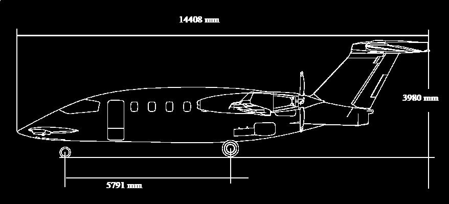
7 3 SPECIFICATIONS 3.1 EXTERNAL DIMENSIONS Wing Span (without winglets) ft m Aspect Ratio Sweep (leading edge) 1 11' 24" Dihedral 2 00' 00" Area ft m 2 Wing Loading (w/o winglets) 70,26 lb/ft kg/m 2 Forward Wing Span (without wing tips) ft 3.28 m Aspect Ratio 4.92 Sweep (@ 25% chord) 0 00' 00" Dihedral -5 00' 00" Area ft m 2 Horizontal Tail Span (without fairings) ft 4.18 m Aspect Ratio 4.57 Sweep (@ 25% chord) 29 48' 00" Dihedral -5 00'00" Area ft m 2 Vertical Tail Span 7.70 ft 2.35 m Sweep (@ 25% chord) 40 00' 00" Area ft m 2 Landing Gear Track 9 ft 4.0 in 2.84 m Wheelbase 19 ft 0.0 in 5.79 m Overall Dimensions Length (without tail tip light) 47 ft 3.2 in m Height 13 ft 0.7 in 3.98 m Span 47 ft 0.9 in 14.35m 7


8 8
9 3.2 INTERNAL DIMENSIONS AND VOLUMES Cabin Dimensions Height 5 ft 9 in 1.75 m Width 6 ft 1 in 1.85 m Cockpit Length 4 ft 9 in 1.45 m Passenger Cabin Length 14 ft 11 in 4.55 m including Lavatory Length 2 ft 7 in 0.79 m Total Length 19 ft 8 in 6.00 m Cabin Volume Cockpit ft m 3 Passenger Cabin ft m 3 Total Volume ft m 3 Cabin Door Dimensions Height 53 in 1.35 m Width 24 in 0.61 m Baggage Compartment Dimensions Total Length 5 ft 7 in 1.70 m Total Volume 35 ft 3 1. m 3 9
10 With Increased Range Option Standard 3.3 WEIGHTS CORPORATE VIP Maximum Ramp lb 5511 kg Maximum Take-off lb 5489 kg Maximum Landing lb 5216 kg Maximum Zero Fuel 9800 lb 4445 kg Standard Equipped Empty (1) 8150 lb 3697 kg Standard Operating Empty (2) 8350 lb 3787 kg Useful Load (3) 3800 lb 1724 kg Usable Fuel 6.70 lb/gal) (4) 2802 lb 1271 kg Maximum Net Payload (5) 1450 lb 658 kg Fuel with Max. Net Payload (6) 2350 lb 1066 kg Net Payload with Max. Fuel (7) 998 lb 453 kg Increased Range Equipped Empty (8) 8200 lb 3720 kg Increased Range Operating Empty (2) 8400 lb 3810 kg Useful Load (3) 3750 lb 1701 kg Usable Fuel 6.70 lb/gal) (9) 3200 lb 1451 kg Maximum Net Payload (5) 1400 lb 635 kg Fuel with Max. Net Payload (6) 2350 lb 1066 kg Net Payload with Max. Fuel (7) 550 lb 250 kg NOTES (1) Assuming standard Corporate 4 interior configuration with De Crane seats/divan; no options included. Does not include weight of crew. Weight may vary depending on interior configuration and options selection. For reference only. (2) Includes one pilot at 200 lbs. (3) Maximum ramp weight less operating empty weight. (4) Equal to U.S. gallons or 1,583 litres (5) Zero fuel weight less operating empty weight (6) Useful load less maximum net payload. (7) Useful load less full fuel weight. (8) Standard Equipped Empty plus 50 lbs (net weight increased range option). (9) Equal to 476 U.S. gallons 1802 litres 10
11 3.4 PRESSURIZATION The structure supports a nominal maximum cabin pressure differential 9.0 psi. Differential 9.0 psi.62 bar S.L. Cabin to: ft 7315 m Cabin certified ceiling 6600 ft 2012 m Certified Ceiling ft m 3.5 POWERPLANT Engines Manufacturer PRATT & WHITNEY OF CANADA Model PT6A-66B (1) Power (each) (flat rated from 1630 thermodynamic HP) 850 SHP (634 kw) Power Loading 7.12lb/SHP (3.23 kg/shp) TBO 3600 hours NOTES: (1) Equipped with torque limiter set to 2495 lb*ft. Propellers Manufacturer Model Diameter Type TBO HARTZELL HC-E5N 86,5 in ( 2197 mm) Five-blade scimitar, constant speed, fully feathering, hydraulically operated 3600 hours 11
12 3.6 PERFORMANCE TAKE-OFF, LANDING AND ALTITUDE PERFORMANCES Take-off Distance (1), S.L., ISA 3196 ft 974 m Landing Distance (2), S.L., ISA (*) 3282 ft 1000 m Rate of Climb, S.L., ISA MTOW lbs MTOW lbs Both Engines 2950 ft/min 899 m/min One Engine Inoperative 785 ft/min 239 m/min Both Engines 2770 ft/min 844 m/min One Engine Inoperative 697 ft/min 212 m/min Service Ceiling Both Engines ft m One Engine Inoperative ft 7254 m NOTES: (*) Distance obtained by flight testing as per the EASA/FAA rules, without propeller reversing, distance certification pending (1) FAR 23 runway requirement (2-engine Take-off to clear 50 feet) for turboprop aircraft. (2) Total distance over 50 feet, full flaps, without propeller reversing. Does not include any runway factors for destination or alternate airports. 12
13 3.6.2 NOISE The aircraft is compliant with certification noise levels specified in FAR 36, Appendix G, Amdt. 16 and in ICAO Annex 16 Chapter CRUISE PERFORMANCE Maximum Speed (3) 402 KTAS 745 km/h Cruise Speed at Maximum Cruise Power (4) At ft 400 KTAS 741 km/h At ft 386 KTAS 715 km/h At ft 357 KTAS 661 km/h IFR Maximum Cruise Range (at Maximum Range Power): Range with Corporate VIP Configuration (5) At ft Standard Configuration (6) 1460 nm 2704 km Standard Configuration with Increased Range Option (7) 1620 nm 3000 km Range with Shuttle Configuration (8) At ft Standard Configuration (6) 1490 nm 2760 km Standard Configuration with Increased Range Option (7) 1770 nm 3278 km NOTES: (3) At feet and ISA Conditions. (4) Typical mid-cruise weights (operating weight + 4 PAX + 1/2 full fuel) ISA conditions and IFR reserves. (5) Assuming standard Corporate 4 interior configuration with De Crane seats/divan; no options included. (6) Mission with 1 pilot + 4 PAX, ISA conditions, zero wind. (7) Mission with 1 pilot + 4 PAX, ISA conditions, zero wind. additional fuel tank configuration (8) Assuming Layout Option 10 interior configuration with High Density seats; no options included. 13
14 3.7 OPERATING SPEEDS Stall Speed, Landing Configuration VSO 95 KIAS 176 km/h Maximum Operating Speed Limits VMO MMO Maximum Flap Operating Speeds VFO flaps MID VFO flaps DN Maximum Flap Extended Speeds VFE flaps MID VFE flaps DN Maximum Landing Gear Operating Speed VLO Maximum Landing Gear Extended Speed VLE Minimum Control Airspeed VMCA Maneuvering Speed VA 260 KIAS 482 km/h 0.7 Mach 170 KIAS 315 km/h 150 KIAS 278 km/h 183 KIAS 339 km/h 177 KIAS 326 km/h 181 KIAS 335 km/h 185 KIAS 343 km/h 100 KIAS 185 km/h 202 KIAS 374 km/h 14
15 Altitude [ft] Altitude 3.8 PERFORMANCE CHARTS P Flight Envelope Mach VC 100 VC 150 VC VC VC True airspeed [KTAS] 0 15
16 Avanti EVO Range Vs Payload with and without Extra Fuel Tank (Chart referred to Shuttle Layout) 16
17 Avanti EVO Specific Range Speed (Cruise Weight 10,000 lbs, ISA Conditions) 17

 high and 24 inches (610 mm) wide.")
18 4 AIRFRAME 15 ft 6 5 ft ft ft 4.1 FUSELAGE GROUP Avanti EVO's aluminum fuselage is circular in cross section and tapers both fore and aft. Cabin width extends to 6 feet 1 inch (1854 mm) and a dropped aisle provides a cabin height of 5 feet 9 inches (1753 mm). The two-part cabin door is located on the left-hand side of the fuselage and is 53 inches (1346 mm) high and 24 inches (610 mm) wide. The upper half of the door is side-hinged and swings forward to open. The lower cabin door, which has two steps, is bottom-hinged and opens downward. 18
19 A plug-type emergency exit hatch is located on the right-hand side of the cabin immediately opposite the cabin door. The aft fuselage extends from the aft pressure bulkhead to the tail-cone and is divided into two sections: the wing/fuselage intersection area and the baggage compartment area. Within the wing/fuselage intersection area, the space over the wing and between the forward and central bulkheads contains an integral fuel tank. This tank is divided into two parts by a centre panel and is interlinked with the wing tanks. Located in the fuselage beneath the wing are most major accessories. The baggage compartment is located in the aft part of the fuselage between the third wing spar and the tail-cone. Baggage compartment length is 5 feet 7 inches (1700 mm) and total volume is 35 cubic feet (1.00 m3). The baggage door is a composite part and is hinged at the top. The tail-cone is attached to the rear fuselage and supports the empennage. 4.2 WING GROUP Avanti EVO is a three-lifting-surface design using a forward wing, an aft fuselage, midmounted main wing, and a stabiliser at the tail. The wing is characterized by an aspect ratio of 11.96, a taper ratio of.34, a dihedral of 2 and a swept of 1 11' (leading edge). The airfoil thickness varies from 13% at the tip to 14.5% at the nacelle; inboard the nacelle, the wing has an average thickness of 13.5%. The wing is provided with a carbon fiber winglet which is characterized by an aspect ratio of 1.39, a taper ratio of 0.54, a cant angle of 19.2, a sweep angle of at leading edge, a toe angle of 1. The high-aspect-ratio main wing is constructed of aluminum alloy. The wing main box is a working skin type (wing panels and spars are machined, stiffeners are integral) with two main spars. The wing has a third spar running from the nacelle to the fuselage centerline. Connected to the main box are an aluminum leading edge and aluminum and composite trailing edges. The wing incorporates inboard single-slotted flaps, outboard Fowler flaps, ailerons and engine support structure (engine cradles are made of titanium alloy). The wing contains an integral fuel tank out to feet (6503 mm) from fuselage centre line. Wing leading edge anti-ice is accomplished by directing engine bleed air through a diffuser duct installed in the main wing leading edge. The forward wing is an all aluminum alloy unit. The wing main box is a working skin type (wing panels and spars are machined, stiffeners are integral) with two main spars, like the main wing, and is attached to the lower fuselage at four points. The aluminum alloy leading edge, contains an electrically-activated de-icing blanket. Single-slotted forward wing flaps are fulldepth honeycomb aluminum parts. The forward wing tip is an Hoerner tip like shape, it is in fiberglass and has an aerodynamic re-balancing function that undoes the increasing of aircraft pitching moment due to the winglet installation. 4.3 EMPENNAGE GROUP The tail group consists of a fixed vertical fin, two ventral (delta) fins, a movable stabiliser with elevators, and a rudder with trim tab. Aerodynamically and mass-balanced elevators are made of full-depth aluminum honeycomb with aluminum skins and a single spar. Each elevator is actuated by means of an aluminum torque fitting attached to the inboard end of the spar. The all-movable stabiliser is a two spars sandwich construction of graphite fabric, surrounding a Nomex honeycomb core. The vertical fin is attached to the tail-cone bulkheads by four vertical aluminum machined spars. Skins are of aluminum 19
20 sheet chemically milled to reduce weight. The rudder is a two spars structure with spars and skin in aluminum alloy; it has a trim tab located in its trailing edge. The rudder is aerodynamically balanced by a leading edge horn and mass balanced by adjustable weights in this horn. The rudder is actuated by means of an aluminum torque fitting attached to the lower end of the front spar and to the reinforced lower close-out cap. Composite Components 20
21 5 POWERPLANT Two Pratt & Whitney Canada PT6A-66B turboprop engines are mounted in titanium engine cradles atop the main wing in composite-construction nacelles. The PT6A-66B is a light-weight, free-turbine engine, with a maximum thermodynamic rating of 1,630 (1,215 kw) horsepower and flat rated to 850 shaft horsepower (634 kw). Each engine utilizes two independent turbine sections: one driving the compressor in the gas generator section and the second one (a two-stage power turbine) driving the propeller shaft through a reduction gearbox. Fire warning is provided by a continuous-type thermal detector running through each engine compartment around and along the engine. The fire protection system installed on P.180 Avanti EVO detects the presence of a fire or of a local overheat condition in the engine fire zones. The engine fire extinguishing system discharges extinguishing agent into the fire zones when it is activated by the flight crew. Two identical systems are installed, one for each engine. The fire bottles are carbonhalon steel containers attached to the engine mounting frames. The stainless steel tubes and nozzles duct the extinguishing agent to the fire zones and to the propeller gearbox zones. The system is activated through two lighted pushbuttons installed on glareshield left and right sides. They are guarded to prevent inadvertent discharge of the fire bottles. The engine fire extinguishing system has been certified on a non-dangerous basis. No tests to demonstrate the extinguishing agent concentrations in nacelle zones have been carried out. The engines drive two Hartzell, five-bladed, aluminum, counter-rotating, pusher propellers scimitar type optimized for 1800rpm, with the left-engine propeller turning clockwise and the right-engine propeller turning counter-clockwise. The left engine is equipped with a standard gearbox which incorporates a modification allowing reverse prop shaft rotation. The aircraft has no critical engine due to opposite-rotation propellers. Woodward propeller governors are fitted with an integral Beta valve, permitting reverse thrust operation. The propellers are also equipped with an autofeather system. The P180 is equipped with a propeller synchrophaser system as to reduce noise during cruise, controlling the relative phase between propellers and, based on phase error, changing props RPM to restore the selected relative phase position. The synchrophaser system may be engaged after takeoff and automatically disengages in the case of in-flight engine shut-down or propeller feathering. The P.180 is equipped with conventional push-pull manual controls including, for each of the two power plants, an engine power output control lever and a combined propeller control and fuel condition lever. These levers are mounted together in a control box assembly located on the control pedestal in the flight compartment, with Power Levers on the left side and Condition Levers on the right. Engine nacelle section 21
22 6 SYSTEMS 6.1 LANDING GEAR The landing gear is hydraulically operated and fully retractable. Shock absorption on all three gear is via air-oil struts. The double-wheel nose gear retracts forward into the nose section, while the singlewheel main gear retract backwards into the aft fuselage. Doors completely cover the retracted gear. The rear door of the nosegear well and the forward doors of the main-gear strut wells remain open when the gear is extended. The side-hinged wheel well doors of the nose gear and the aft doors of the main gear open with gear extension and then close when the gear is fully extended. The nose gear is equipped with an electrohydraulic Class B (according to SAE ARP1595) steering system with an integrated rack-and-pinion type steering actuator. The nose gear is steerable through 50 degrees left and right in the TAXI mode, and 7 degrees left and right in the Take-Off & Landing mode. Full time use during T/O & Landing with automatic engagement / disengagement. The steering system is automatically armed when nose landing gear is down-andlocked; when in air it will command nose wheels centered while when on ground it will automatically select Take-Off & Landing mode. Pilot selection is required to operate in Taxi mode. The electro-hydraulically operated nosegear steering is controlled through the rudder pedals. A control-wheel-mounted push button is used to select the steering mode. Both pilot and copilot can disarm the steering system at any time via the Control Wheel Master Switches located on pilot s and copilot s control wheel handles. The system shall automatically disarm upon gear retraction or failure detection. The landing gear can be extended at speeds up to 185 KIAS. The gear actuators incorporate both internal up and down locks. A warning horn will sound under the following circumstances: the landing gear is not locked down and power is reduced below a setting sufficient to maintain level flight; the flaps are lowered to the down position without the gear locked in the down position; the flaps are set to the mid position and the left power lever is retarded approximately below the half-travel position. The emergency landing gear extension system consists of a hydraulic hand pump, an emergency select valve and emergency lines from the fluid reservoir to the actuators. Toe-actuated BF Goodrich carbon disc brakes are installed on the main gear wheels. Brakes are hydraulically actuated through a primary system or a secondary, emergency system. 22
23 6.2 FLIGHT CONTROLS Control surfaces are mechanically connected to the pilot controls via cables, pulleys, push-pull rods and bell cranks in a closed loop system. Primary controls consist of ailerons, elevators and rudder. The pilot controls consist of a control wheel hinged on a yoke control column and adjustable rudder pedals hinged on the cockpit floor, in a dual-pilot control configuration. Differential ailerons provide roll control. An autopilot rotary actuator may also drive the ailerons quadrants. An aileron trim tab is installed on the right aileron. It has to be noted that winglet has been carefully designed to maintain favorable aileron behavior. Lateral (roll) Control System The pitch control system consists of an all moving stabiliser-elevator assembly. The trim system for this control is an electromechanical actuator which controls the stabiliser angle of attack. The autopilot system may drive both the horizontal tail trim actuator and an autopilot rotary actuator connected to the elevator. The elevator provides primary pitch control and consists of two surfaces separately hinged to the stabiliser. Longitudinal (pitch) Control System 23
24 An up-down spring mechanism, linked to the stabiliser, is installed in the longitudinal control system to provide a suitable pilot column stick force through the complete centre-of-gravity range, to provide increased stability at high speed and to improve trimmability at low speed. The rudder controls the aero plane directionally about its vertical axis. A cables circuit, push-pull rods and a bell-crank assembly connect rudder pedals quadrant to rudder quadrant. An autopilot rotary actuator may also drive the pedals quadrant. The flight control system uses no dampers, stick-pushers or boosted control mechanisms. Secondary control is provided by the aileron and rudder trim tabs for roll and yaw, and by the all-movable stabiliser for pitch. All trimming surfaces are electrically operated and controlled. Directional (yaw) Control System Pitch trim is accomplished by repositioning the stabiliser to the desired trim setting through actuation of the horizontal pitch trim actuator. The three-motor, screw-jack type actuator has a primary and a secondary mode of operation. Longitudinal trim is mechanically fail-safe. A rudder trim tab, hinged to the trailing edge of the rudder, is operated by an electro-mechanical actuator installed in the vertical fin. An aileron trim tab, hinged to the right aileron, is operated by an electromechanical actuator installed in the wing. The Avanti EVO flap system consists of three mechanically independent sets of flaps: main wing outboard flaps, main wing inboard flaps and forward wing flaps. Each set of left and right main wing flaps are mechanically interconnected. The operation of all flaps is synchronized by an electronic control unit that controls the power supply to the flap D.C. motors. A drive unit, located in the centre of the fuselage, actuates the main wing inboard and outboard flaps. Additionally, forward wing flaps are electrically driven by actuators in the forward wing. 24
25 There are three discrete flap positions controlled by micro-switches: up, midtakeoff position, down-landing configuration. From the up- to the midsetting, flap deployment takes 16 seconds. Flap travel is sequenced to minimize pitch change through flap deployment. From the mid setting, all flaps descend simultaneously to the down setting in five seconds. Flaps retract simultaneously to the mid position in five seconds. From the mid position flaps retract simultaneously to the up position in 16 seconds. The flap position indicator, shown on the central Multi Function Display, provides the crew with visual indication of flap surface positions. Flap System 25
26 6.3 FUEL SYSTEM The fuel system has a baseline total fuel capacity of U.S. gallons (2,848 lbs, 1,597 liters), with a usable fuel of U.S. gallons (2,802 lbs, 1,583 liters). Fuel System Each engine is fed by its own fuel system made up of four interconnected tanks: an integral fuselage tank just above the wing, a wet-wing tank, one fuselage under-wing collector tank and one auxiliary collector tank also located in the fuselage below the wing. The aircraft can be optionally equipped with an additional fuel tank to improve aircraft flight range by increasing the available fuel volumes without affecting present MTOW. The tank add 58 U.S. gallons (390 lbs, 220 litres), for a total fuel capacity of 480 US Gallons, with usable fuel system capacity of 476 U.S. gallons (3218 lbs, 1,802 litres). The additional fuel tank has been designed to avoid any extra work to the crew both in air and on ground, since refueling and unloading operations remain unchanged (ref. 9.1 for further details). The left and right fuel systems are independent except during pressure refueling operations, during which a valvecontrolled interconnecting duct connects the left and right collector tanks. A single point pressure refueling adapter is provided on the right side of the fuselage under the wing. All the fuel is supplied to the engine from the fuselage collector tank. Two electricallydriven submerged boost pumps, located at the bottom of the collector tank, are connected to the fuel low pressure line to the engine. The main boost pump normally supplies fuel to the engine driven fuel pump; the stand-by pump automatically switches on in the event of main pump failure. A capacitance-type fuel gauging system is used to indicate the fuel quantity, which is shown in pounds. The fuel tanks have been coated to provide corrosion resistance and protection against micro-organism damage. 6.4 HYDRAULIC SYSTEM The hydraulic system provides hydraulic power for nose wheel steering, wheels braking, landing gear extension and landing gear retraction. Hydraulic power is generated by a hydraulic package whose main components are a variable displacement pump, a reservoir, a low pressure filter and a landing gear selector valve. Two master cylinders with independent lines are provided to allow normal and emergency braking. The hydraulic power package operates in three modes. High Duty Mode (HDM) is selected for landing gear extension and retraction. The HDM pressure range is 1,800 to 3,000 psig (124 to 207 bar). Low Duty Mode (LDM) is selected when landing gear extension has been completed and is the normal operating mode for steering and braking. The LDM pressure range is 800 to 1,200 psig (55 to 83 bar). Non Operating 26
27 Mode is selected automatically when the landing gear is retracted or the pilot has switched the power unit off. An electrical depressurizing valve automatically selects HDM or LDM. The hydraulic system uses a hydraulic fluid according to MIL-H-5606 specification and is pressurized by bleed air. 6.5 ELECTRICAL SYSTEM A dual parallel main bus distribution system is laid out so that, in the event of failure of a single power source or of a distribution system, power is maintained to essential equipment by the essential bus. The essential bus is energized by three paths, each equipped with one circuit breaker and one reverse current blocking diode. This ensures that the essential bus remains active with two independent faults in the feed cables. The distribution function is ensured by a dual (internally segregated Lh and Rh side) Main Junction Box, located in the equipment section forward to the baggage volume, and by two (Pilot and Copilot side) Circuit Breakers Panel, located in the cockpit. The new Main Junction Box provides improved reliability and enhancements on segregation and growth capacity. Two 28 Volt, 400 Ampere D.C. starter / generators in parallel provide torque for engine starting and generate D.C. electrical power. One 25.2 Volt, 38 Ampere-hour nickelcadmium battery, located in the front section of the rear baggage compartment, provides power for starting and also serves as a reserve source of emergency electrical power in case of dual generator failure. A 5Ah@24VDC Emergency Power Unit is provided to supply a subset of emergency systems (Standby, COM1,..). Generator control units are able to maintain the output voltage of the generators at a constant level during variation in engine speed and electrical load. The electrical system is automatically protected from over-voltage and reverse current. No AC power is required for the avionics systems. Two small dual voltage inverters, located in the cockpit, are used for powering and dimming both the electroluminescent AC panels and the incandescent DC panels/bezels. An external power receptacle, located on the left side of the fuselage just above the main gear well and provided with overvoltage protection, allows the use of an auxiliary power source to either start the engines or perform an extended ground check of the electrical equipment. DC power distribution 27
; two landing lights (one each on the legs of the main landing gear) and one taxi light (on the nose")
28 6.6 LIGHTS The aircraft is equipped with the following lights: two winglet (red and green, forward facing) position lights, one vertical fin top fairing (white, rear facing) position light ; two anti-collision strobe lights (one on top of the vertical fin and one on the bottom fuselage); two landing lights (one each on the legs of the main landing gear) and one taxi light (on the nose landing gear leg); one wing inspection light on the left outboard nacelle surface; one recognition/approach light located on the top of the vertical fin leading edge. TAXI LIGHT External Lights 28

29 6.7 PRESSURIZATION AND ENVIRONMENTAL SYSTEM The environmental control system utilizes engine bleed air for heating, cooling, and pressurizing the cabin; one engine is capable of sustaining the operation of the entire system. Two outflow valves located on the rear pressure bulkhead regulate cabin pressurization. The pressurization controller provides both an auto-schedule mode and a manual control. The 9.0 psi (.62 bar) system provides a 6,600 feet (2012 m) cabin altitude at 41,000 feet (12500 m) and maintains a sea-level cabin up to 24,000 feet (7315 m). The new Environmental Control System provides a fully automatic, dual zone, integrated bleed air heating and vapor cycle cooling system (VCCS) ECS controller; it will automatically and independently manage the cabin and cockpit temperatures in both cooling and heating modes with an increase in cooling power of about 25%. The integrated Environmental Control Unit is packaged to fit into the area below the P.180 baggage compartment. Bleed air from the engine first enters a precooler which reduces the temperature to an adequate level, then through a shut-off valve, a check valve and a pressure regulator reaches the ECS Gate valve. The bleed air is divided into two flows; one enters the air to the air heat exchangers to produce a colder flow; the other one is bypassed and then mixed to the colder flow through the two mixing valves. The already mixed airflow is provided to passenger cabin and cockpit through two separated check valves. The airflow is distributed in the passenger area through overhead and floor diffusers, and in the cockpit area through adjustable outlets, lateral and floor diffusers. The controller is primarily managed by a dedicated ECS Control Panel, installed in the cockpit on pilots side instrument panel, providing both full Auto and Manual control possibility. In the passenger cabin, a RH and a LH LCD control panels, used in conjunction with RH and LH cabin evaporator, will provide advanced control to obtain different outlet temperatures between the left outlets and the right outlets and give the passengers a semi-zone control within the limits of the cabin zone set-points. Manual modes are also provided to allow manual control of mixing valves position, evaporator blower speeds and airconditioning compressor operation. The controller and cockpit control panel will also be designed to ensure adequate manual control in the event of a controller logic failure. 29
30 6.8 OXYGEN SYSTEM A 40 cubic feet (1.13 m3) storage cylinder is installed on the left side of the fuselage under the cabin floor aft of the cabin door. Oxygen is supplied to pilot and co-pilot positions through quick-donning diluter/demand masks. Automatic drop-out, constant flow oxygen masks are provided at each passenger position. 6.9 ICE PROTECTION An ice detector probe is located on the right side of the aeroplane nose. When a 0.5 millimeter thickness of ice accumulates on the probe, an amber ice caution light is illuminated on the instrument panel. A visual ice accretion probe, located adjacent to the pilot's windshield, is provided as a back-up to the ice detector. A wing inspection light is installed on the outboard side of the left engine nacelle to allow the pilot to check icing conditions during night flight. Main wing leading edge anti-ice is accomplished by directing engine bleed air through a diffuser duct installed in the main wing leading edge. The forward wing contains an electricallyactivated de-icing blanket on the aluminum alloy leading edge. Nacelle inlets are de-iced by pneumatic boots. To avoid ice ingestion, an inertial separator is installed inside each nacelle. Moreover, the cycling of the nacelle boots is automatically controlled by the Ice Detector System in its primary mode of operation. A timer is provided to cycle the boots for secondary operations. Electric heating of the windshield on both pilot and co-pilot sides is used to guard against or alleviate icing and fogging. No ice protection is provided or required on the horizontal and the vertical tail. 30
31 7 INSTRUMENTATION AND AVIONICS 7.1 GENERAL The cockpit layout of the Standard Configuration includes two complete crew stations equipped with dual controls, including control columns, adjustable rudder pedals and brakes. Crew seats are fully adjustable and include four-point restraint harness. An emergency oxygen system provides two diluter/demand masks for the crew members. Cockpit lighting includes dome LED lights, instrument panel flood lights, internallylighted instruments and dual map lights. Two heated Pitot tubes and two heated static ports (each one with two independent sources) provide dynamic/static pressure to flight instruments. Independent sources are used to drive the pilot's and co-pilot's flight instruments. 7.2 ELECTRONIC FLIGHT DISPLAYS The Rockwell-Collins Pro Line 21 Electronic Flight Instrument System (EFIS) is an integrated system able to gather, concentrate, and display aircraft information to the flight crew. The EFIS includes the following units: Three 8 x10 colour Liquid Crystal Adaptive Flight Displays (AFD) with LED backlight Two Display Control Panels (DCP) One Cursor Control Panel (CCP) An Integrated Avionics Processor System (IAPS) Four Data Concentrator Units (DCU) configured as a Multi-Function Display (MFD) shared by the pilots. Each PFD provides attitude, heading, airspeed, altitude, vertical speed, Flight Control System (FCS) annunciation, and navigation data on a single, integrated display. The PFDs also display Engine Indication System (EIS) information if selected in reversionary mode. EIS information is always displayed on the MFD. The PFDs can display a full Compass Rose, a partial Compass Arc, or a flat Compass Tape immediately beneath the attitude ball. Current heading is read opposite the lubber line. This display incorporates a pilot controllable Selected Heading Bug. The heading bug is controlled by the HDG rotary knob on the Flight Guidance Panel (FGP). The PFDs also provide a Track Pointer, wind data, lateral navigation course and deviation data, distance data, Marker Beacon information, ILS information, vertical deviation data, VNAV deviation data, radio altitude, Decision Height and Minimum Descent Altitude, map display and a Flight Management System (FMS) Message Window. Three AFDs with identical shape are arranged on the instrument panel as shown in Figures at pages 40 and 41. Under normal conditions the two lateral displays are configured as Primary Flight Displays (PFD) and the central display, Ethernet capable, is 31
32 7.3 MULTI-FUNCTION DISPLAY (MFD) The MFD includes three major display areas: the Engine Indication System (EIS) region and the upper and lower Multi- Function Windows (MFW) below it. The EIS region is displayed across the upper portion of the MFD. The area below the engine instruments is divided into upper and lower format windows. The contents of both format windows can be separately controlled by the pilot. The EIS area continuously shows engine parameters. The engine display format consists of a full time window showing: ITT and Torque, both in digital form and on a shared analogue gauge (one for each engine), Propeller RPM and NG, both in digital form and on individual smaller analogue gauges (one for each engine). Digital only displays for Fuel Flow, Fuel Quantity, Oil Pressure and Oil Temperature are located on the right part of the EIS window. There are two independent sources for the primary engine parameters (ITT, Torque, NG and Prop RPM) for each engine: one is the Data Concentrator Unit (DCU) and the other is the Engine Data Concentrator (EDC). The DCU is normally the source of all displayed engine data and the EDC is a secondary source of all displayed engine data. The Upper MFW can display either a Checklist or a FMS Text Window. The Lower MFW can show either a compass rose, a compass arc, a present position map (PPOS), a plan map, TCAS only information (with option installed), the Systems Page, Enhanced Maps (optional; over the PPOS or Plan Map) or Graphical Weather data (optional). The turbulence radar images are displayed on the arc or PPOS data The Upper MFW and Lower MFW can be merged into a Full Format window showing either the FMS remote text, the Status menu (including Database effectiveness, Charts Subscription, Maintenance Main Menu, FCS Diagnostic, optional File Server configuration), Electronic Charts (optional) or video display (optional). The ProLine 21 system may include an optional File Server Unit (FSU) providing electronic charts, enhanced map features (e.g., rivers, lakes, geopolitical boundaries, airspaces and airways) and uplinked graphical weather. The FSU is connected to the Ethernet-capable MFD providing a control interface to these enhanced features using the Cursor Control Panel (CCP); both Ethernet capable MFD and CCP are installed as standard features. Further information is provided in the Options section of this document. 7.4 RADIO SENSOR SYSTEM The Radio Sensor System (RSS) is made up of a single CDU-3000 display unit and a single RTU-4200 tuning unit providing a primary LCD-based integrated display system for communication and navigation operations within the Air Traffic Control environment. The basic communication system includes two VHF-4000 Communication Transceivers, two TDR-94D ATC Enhanced Mode-S Diversity Transponders, one DME transceiver (a second receiver is optional), one NAV-4000 VOR/ILS/MKR/ADF receiver and one NAV-4500 VOR/ILS/MKR Receiver. 7.5 FLIGHT MANAGEMENT SYSTEM The FMS-3000 satellite-based navigation system provides the capability to perform en route, terminal, and non-precision approach lateral navigation with provision for LPV approaches upgrade (optional). The system contains an advanced GPS-4000S Global Positioning System SBAS (Satellite Based Augmentation System) receiver which processes the transmissions from multiple GPS satellites simultaneously to calculate navigation solutions based on information from all satellites in view. The Attitude Heading Reference System 32
33 (AHRS), Air Data Computer (ADC), DME and VOR data are also used by the FMS. The FMS provides necessary controls for all input sensors, if appropriate. A Coupled VNAV interface with the FCS allows the FMS VNAV function to select various FCS vertical modes of navigation. The FMS interfaces with the Data Base Unit (DBU) to update, through a USB drive, its internal Data Base and with the EFIS Displays to provide conventional navigation information and state-of-the-art map presentation. 7.6 WEATHER RADAR SYSTEM The Rockwell-Collins RTA-852 Turbulence Detection Radar is a stabilized, solid state, X-band color radar system. The weather and map information can be overlaid on either or both PFDs and MFDs on most of the navigation display formats. The Control Panels provide the radar mode menu selection, range select knob, tilt knob and ground clutter suppression button. With two PFDs operational, each display is controlled separately by its own Display Control Panel (DCP) and updated on alternate antenna sweeps. 7.7 FLIGHT CONTROL SYSTEM The fail safe Flight Control System (FCS) is made up of a dual Flight Guidance System and of a 3 axis Autopilot, including Yaw Damper and Pitch Trim control. The pilot selects the Flight Guidance Computer (FGC) in control with the Flight Guidance Panel s (FGP) coupling (CPL) switch. Each PFD displays the Flight Director (FD) commands from the Flight Guidance Computer selected with the CPL switch, except for Go Around (GA) and Approach (APPR) modes. The GA and APPR modes are Independent Modes, and only the on-side Flight Guidance Computer guidance is used by the associated PFD for Independent Modes. 7.8 STAND-BY INSTRUMENTS An L-3 Communication integrated stand-by instrument located on the top of the centre instrument panel and supplied by an emergency battery provides essential flight parameters in case of loss of primary sensors or displays. 7.9 ELT An Artex C406 3-frequency Emergency Locator Transmitter transmits on the two Emergency Frequencies of and MHz as well as on the satellite frequency of MHz. The system is activated either automatically by a g-switch or by the crew through a switch located in the cockpit INTEGRATED FLIGHT INFORMATION SYSTEM (IFIS) The IFIS provides capability to display maps (airways, airspace boundaries, geopolitical data), Jeppesen charts (airport charts, approach charts, en-route charts) or weather graphical information on the Multi Function Display. It includes the following: Rockwell-Collins FSU-5010 File Server Unit (FSU) Rockwell-Collins FSA-5000 File Server Application software Rockwell-Collins ECU-3000 External Compensation Unit 7.11 ELECTRONIC CHARTS FOR IFIS Jeppesen charts (airport charts, SID and STAR charts, Instrument procedure charts, en-route charts) Rockwell-Collins ECH-5000 are installed on the FSU for visualization in the Multi Function Display. The Chart image files are stored in the FSU and are selected for display via the Chart Main Menu. The Cursor Control Panel provides an interface with the Chart Main Menu and is also used to manipulate the displayed chart. The chart feature also provides a depiction of the aircraft's current 33
34 position on all charts that have been geographically referenced. It requires subscription to the Jeppesen Charts Update Service ENHANCED MAP OVERLAY FOR IFIS It provides the capability to display geopolitical data, airways and airspace maps on the Multi Function Display. It includes the installation of the following additional software: Rockwell-Collins OVL-5000 Enhanced Map Overlays Map displays are controlled via the Cursor Control Panel or via line select keys to access the Map Menu. In order to prevent display clutter, each of the enhanced map overlays is automatically removed as map range is increased. The airways and airspace depictions are removed when range is increased over 100nm. The geopolitical map data is removed when map range is increased over 300nm. It requires subscription to the Rockwell-Collins Map Service TCAS I An L-3 Communications Skywatch HP model SKY899 TCAS I airborne Traffic Alert and Collision Avoidance System (optional kit) is provided as standard equipment. The TCAS I system interrogates ATC transponders in nearby aircraft and uses computer processing to identify and display potential and predicted collision threats along with an aural warning when requested. TCAS I traffic information can be selected for pictorial display on the PFD and/or the MFD to indicate the presence of other aircraft within a selected range around the aircraft TAWS An L-3 Communications Landmark Class-B model TAWS 8000 Terrain Awareness and Warning System (optional kit) is provided as standard equipment. The system provides traditional Ground Proximity Warning System (GPWS) functionality to prevent Controlled Flight Into Terrain, enhanced by a stored worldwide database including terrain, airport and obstacle data. TAWS provides the pilot with predictive warnings based on comparison between stored obstacle data and a prediction of the aircraft s flight path derived from FMS and GPS data and current flight parameters. TAWS provides aural and visual warnings to alert the pilot in case a hazardous condition is detected and includes the possibility to represent terrain elevation features on the AFDs graphically IRIDIUM SATELLITE PHONE An AirCell ST3100 Iridium Satcom system (optional kit), installed as standard equipment provides worldwide access to the Iridium global satellite network. It includes: An ST3100 transceiver unit located in the passenger cabin and a patch antenna located on the top fuselage A cordless base station located on the top of the forward right hand side partition cabinet in the passenger cabin, in position also accessible from the cockpit. A cordless handset providing voice communications, control functions and programming Two RS232 data ports in the passenger cabin for data (fax/ ) transfer through the Iridium Satellite phone network ADDITIONAL FEATURES The standard ProLine 21 avionics system of the P.180 provides the capability to operate in RVSM-airspace and to perform Category II approaches and steep approaches. The flight envelope extension to Mach 0.7 Mmo is also a standard feature PROVISIONS 34
35 PROVISION FOR XM/WSI SATELLITE SYSTEM RECEPTION Structural and electrical provisions for XM/WSI Satellite Weather Graphical Information functionality. The provision includes XM antenna, Wiring harness, Structural provision for XM weather receiver AUXILIARY CABIN POWER KIT This kit provides two sockets (40Amps under cabin compartment floor, to provide electrical power either to sanitary or other equipment (if approved). The power is provided both on ground or in flight (at least one generator is properly operating and set on line). 35
36 8 STANDARD AIRCRAFT CONFIGURATION 8.1 AVIONICS, INSTRUMENTS AND CONTROL PANEL Radio Management System Rockwell-Collins RTU-4200, CDU-3000 Dual VHF COM - Rockwell-Collins VHF-4000 Transceiver with Antenna with 8.33 khz spacing VHF NAV1+ADF - Rockwell-Collins NAV-4000 VOR/ILS/MKR/ADF Receiver with Antennae VHF NAV 2 - Rockwell-Collins NAV-4500 VOR/ILS/MKR Receiver with Antennae Single DME - Rockwell-Collins DME-4000 (3 channel) with Antenna Dual Mode S Flight ID Diversity Transponder - Rockwell-Collins TDR-94D Radio Altimeter - Rockwell-Collins ALT-4000 (Operation to 2500 ft) with Antennae Turbulence Detection Weather Radar - Rockwell-Collins RTA-852 Color Radar with 12" Antenna Dual Audio Panel - Baker B1045 Dual Cockpit Speaker Dual hand-held Microphone Dual Boom/Microphone/Headset Telex 850 ANR EFIS with EIS Two Rockwell-Collins displays AFD-3010 with two DCP-3030, One Rockwell-Collins display AFD-3010E with CCP-3000 Flight Guidance System - Rockwell-Collins Dual FGC-3003 (A/P,YD and dual Flight Director included), three SVO-3000 Servos, single FGP-3000 Flight Guidance Panel Single FMS - Rockwell-Collins FMC-3000 (NAV to NAV and VNAV), CDU-3000 (used also for radio tuning), DBU-5000 GPS Sensor Unit - Rockwell-Collins GPS-4000S Dual ADS - Rockwell-Collins ADC-3000 Dual AHRS - Rockwell-Collins AHC-3000 and FDU-3000 Maintenance Diagnostic System - Rockwell-Collins MDC-3110 Four Data Concentrator Unit - Rockwell-Collins DCU-3001 Stand-by Cluster Instrument L-3 Communications GH-3100 Emergency Locator Transmitter Artex C406 (3 frequency) Dual Digital Clock (Chronometer included) Dual Master Annunciator Dual Turn&Slip Indicator (shown on the displays) Reversionary/Miscellaneous Panel Hobbs meter Integrated Flight Information System (IFIS) including: - Rockwell-Collins FSU-5010 File Server Unit (FSU) - Rockwell-Collins FSA-5000 File Server Application software - Rockwell-Collins ECU-3000 External Compensation Unit Rockwell-Collins ECH-5000 Electronic Charts installation in the FSU Rockwell-Collins OVL-5000 Enhanced Map Overlays installation TCAS I L-3 Communications SkyWatch HP model SKY899 TAWS Class B with Worldwide Database L-3 Communications Landmark model TAWS8000 AirCell ST3100 Iridium Satcom NOTE: RVSM, Mach 0.7, Category II Landings and Steep Approach capabilities are included as standard. 36
37 8.2 ELECTRICAL SYSTEMS AND LIGHTS Two 400A, 28V Starter Generators Two Solid State Generator Control Unit Nickel-Cadmium Battery (38 Ah) Emergency Power Unit (5Ah) External Power Receptacle with Overvoltage Protection Main Junction Box with self test (rear non pressurized volume) Two Circuit Breakers Panels (Lh & Rh side cockpit) providing nine busses DC Distribution System with Auto Load Sharing Dual Solid State Master Warning and Caution Panels with Self Test Solid State Warning and Caution Annunciator Panel with Self Test and Dimmer System Pitot Heating Monitor Static Wicks Heated Stall Warning System with Pre-flight Self Test System One LED Taxi and two LED Landing Lights Two LED Left & Right Position Lights (red & green on each winglet leading edge) One LED Rear Position Light (white, rear facing on vertical fin top fairing) LED Anti-Collision Strobe System (top and bottom) LED Recognition Light (On top of Vertical Fin) LED Wing Ice Inspection Light Cockpit Dome Lights Flood Lights Instrument Lighting System Dual Map Lights in Cockpit Area Cabin Floor LED lighting LED lighting in the passenger cabin and in the toilet area Two 28 VDC Auxiliary Cabin Power Outlets (underneath the cabin floor). 110 VAC power outlets in cockpit (Qty. 2) and passenger cabin (Qty. 4) Two RS232 data ports in the passenger cabin for data (fax/ ) transfer capabilities through the Iridium Satellite phone network only. 8.3 POWERPLANT AND RELATED SYSTEMS Two PRATT & WHITNEY model PT6A-66B Free Turbine Engines flat rated at 850 Shaft Horse Power and Engine Accessories, equipped with Torque Limiter Two HARTZELL HC-E5N 86,5" diameter, five metal blades, scimitar type, fully feathering and reversible, hydraulically controlled, constant speed propellers Magnetic Chip Detector Oil Quantity Dipstick Indicator Primary Propeller Governor Overspeed Propeller Governor N1 and N2 Magnetic Pick-up Speed Sensors Two Power Levers for Forward and Reverse Power Two Condition Levers for Propeller speed, High/Low Idle, Feather and Engine Cut-off Auto Ignition System Submerged electric main and standby Fuel Boost Pumps Fuel Control Unit Fuel Heater System Fuel Crossfeed System Low Fuel Quantity Warning System 37
38 Two Fuel Quantity Indicators (on the Multi Function Display) Two Fuel Flow Indicators (on the Multi Function Display) Fuel Drain System Fuel Tank Interconnect Pressure and Gravity Refueling Low Oil Quantity Warning System Propellers Auto-feather Complete Engine Anti-Icing System with Ice Protected Engine Inlet Engine Parameter Indication on Multi Function Display Engine Fire Detection System Engine Fire Extinguishing System 8.4 SYSTEMS Oxygen System for Pilots (Two Diluter / Demand Masks) and Passengers (Ten Masks) Digital Cabin Pressure Control System with manual back-up Mixed Air Environmental Control System with Freon cooling system Forward Wing Anti-Ice System (Electrical) Main Wing Anti-Ice System (bleed air) Windshield Electrical Anti-Ice and Defogging Hydraulic Power Pack Dual heated Pitot and Static Ports with heating monitor Alternate Heated Static Source Propeller Synchrophaser Steerable Dual Wheel Nose Landing Gear MAGNAGHI Electro-Hydraulic Class B Steering, full time use - EATON Single Wheel Main Landing Gear - MAGNAGHI Main Wheel and Tires ( ) - GOODRICH Nose Wheels and Tires (5.00-5) - GOODRICH Carbon Brakes on each Main Wheel Landing Gear Position Lights, Down and Locked Landing Gear Warning Horn and In-Transit Light Dual Conventional 3-Axis Aircraft Control System Dual Adjustable Rudder Pedals and Toe-Operated Brakes Parking Brake Emergency Landing Gear Extension System (Hand Pump) Electric Aileron Trim Tab (Roll) Electric Rudder Trim Tab (Yaw) Electric Stabiliser Trim Actuator (Pitch) Electric Flap System with Electronic Control Unit and Four Motors 8.5 EMERGENCY EQUIPMENT Portable fire extinguisher Crew and passenger oxygen Emergency flashlight First Aid kit provision 8.6 MISCELLANEOUS AND GROUND SUPPORT EQUIPMENT Cabin baggage straps 38
39 Pitot covers TAT sensor cap Anti-ice detector cap Engine intake blanks Oil cooler inlet blanks Starter generator and inertial separator blanks Air conditioning scoop cap Engine stack caps AOA transducer cap Static wick covers Telescoping tow bar Jack pads Lifting brackets Mooring pads with rings Wheel chocks Gust locks Propeller restrainers Fuel drain tool Tool case Windshield sun shades Access panel for air conditioning service Cockpit pedestal guard Cockpit glare shield check list holder Cockpit seat shoulder belt guide plate assembly Cockpit lower sidewall panels Cockpit control column leather boots Cockpit glare shield Cockpit seats Baggage compartment finishing Baggage compartment protective flap 39
40 Standard Instrument Panel 40
41 ECS CONTROL PANEL Standard Instrument Panel 41

42 9 OPTIONAL EQUIPMENT 9.1 INCREASED RANGE OPTION This option will provide the installation of an additional fuel tank providing a usable fuel capacity of about 58 U.S. gallons (390lbs, 220litres); the tank is divided in two separated parts (29 US Gallons, 195lbs, 110litres each) interconnected respectively to baseline left and right side fuel systems; each part is equipped with a dedicated probe interfaced with aircraft fuel quantity measurement system. As before mentioned, the total usable fuel system capacity with the additional fuel tank will becomes 476 U.S. gallons (3,218 lbs, 1,802litres). Refueling and fuel unload operations remain unchanged. 9.2 AVIONICS OPTIONS ENHANCED SAFETY OF FLIGHT PACKAGE : ACAS II + EGPWS (TAWS CLASS A) Rockwell Collins TCAS 4000 and Honeywell EGPWS Mark VIII replacing standard TCAS I L-3 SKY 899 and TAWS B BF Goodrich Landmark ACAS II 7.1 The Rockwell Collins TCAS-4000 (compliant with ICAO ACAS II Change 7 requirements) improves safety with total situational awareness of impending traffic conflicts, including the display of resolutionary information for immediate threats. The system tracks all Mode C and Mode S transponders within 35nm and provides range, relative bearing and altitude information for the up to 30 aircraft that representing the highest 42
43 collision threat. Traffic Alerts (TAs) and Resolution Advisories (RAs) are given aurally through the aircraft audio system and visually on the PFDs. When other TCAS II-equipped aircraft are encountered, complementary RA maneuvers are coordinated by each system. Resolution Advisory commands appear on the two vertical speed indicators or the vertical speed display fields of integrated electronic flight display systems. NOTE: If requested ACAS II system can be installed also in conjunction with TAWS Class B EGPWS The MK VIII version of Honeywell's EGPWS is a Class A TAWS that helps to prevent accidents caused by Controlled Flight into Terrain (CFIT). The system achieves this by using a number of aircraft inputs, applying proprietary alerting algorithms, and alerting the crew with aural messages, visual indications, and a display of terrain in the event the boundaries of the alerting envelope have been exceeded. System configuration is controlled via a programmable module. The MK VIII offers a worldwide terrain database. Databases are loaded via a convenient ATA format PCMCIA card using Honeywell's SmartCable interface. Note: EGPWS installation is incompatible with SBAS LPV ( ) option HF WIRING PROVISIONS It provides wiring and mounting provisions for later installation of the HF system HF RADIO SYSTEM The Rockwell Collins HF 9000 Radio Communication System can be added to the two VHF Communication Systems to perform long-distance voice communications. High Frequency radio communications allow reliable long range transmission and reception over distances of thousands of miles. This makes HF radio particularly useful when flying over vast surfaces where VHF communications, limited to line of sight transmission, are out of reach INMARSAT SATELLITE PHONE A Thrane & Thrane Aviator 200 Inmarsat Satcom system can be installed in alternative to above Aircell ST3100 Iridium Satcom one. The Aviator 200 using Inmarsat s SwiftBroadband (SB) services can provide an IP connection to ground with a maximum bandwidth of 200 kbit/s to allow, virtually anywhere in the world, a wide range of in-flight capability including , Internet Browsing, Smart Phone Connectivity and Voice Services; it offers also a Built-in wireless connection. The Aviator 200 Swiftbroadband system includes: A SwiftBroadband Unit (SBU) located in the passenger cabin with a configuration module holding the SIM card A low gain antenna located on the top fuselage with a HLD unit (High Power Amplifier, Low Noise Amplifier and Diplexer in one unit). A wired handset/cradle located on the top of the forward right hand side partition cabinet in the passenger cabin, in position also accessible from the cockpit. 43
44 A wireless handset/cradle located on the top of the aft left hand side cabinet in the passenger cabin Note: Aviator 200 installation is not feasible with current ADASd/DTU kit installation (same location) PROVISION FOR IPAD MINI AS EFB This optional provision shall install the means needed for the operation of two Apple ipad mini (not part of the kit) as optional Class 2 / Type B Electronic Flight Bags (EFB). The kit will add, on both pilot and co-pilot side, a device mounting mean in place of the control wheel map holder and a dedicated power supply socket FULL PROVISION FOR CVR INSTALLATION Structural and electrical provisions (wiring and connections) for the L-3 Communications FA2100 Cockpit Voice Recorder COCKPIT VOICE RECORDER The L-3 Communications FA2100 Cockpit Voice Recorder allows recording of all audio signals: signals transmitted or received by the pilot and the co-pilot, cabin page announcements, cockpit conversations, through the cockpit area microphone All audio inputs are fed into 120-minutes recording channels. The FA2100 is provided with an Underwater Locator Beacon (ULB) and a g-switch enables to stop the record in case of impact. The kit includes: A CVR recording unit located in the baggage compartment A CVR control unit located in the pedestal A g-switch located in the vanity area close to the aircraft C.G. A cockpit microphone located on the pedestal top on the RH side The CVR is mandatory in the US and Canada for aircraft equipped with 6 or more passenger seats operating under FAR COCKPIT VOICE RECORDER PORTABLE INTERFACE UNIT The L-3 Communications Cockpit Voice Recorder Portable Interface Unit allows the download of recorded data as well as maintenance and operational checks on the FA2100 Cockpit Voice Recorder unit. During normal operations, it is not usually carried on board of the aircraft. The Portable Interface unit is fully interchangeable and can be used in connection with any L-3 Communications FA2100 Cockpit Voice Recorder unit COCKPIT VOICE AND DATA RECORDER COMBO UNIT (CVDR) In lieu of above Cockpit Voice Recorder a L-3 FA2100 Solid-State Cockpit Voice and Data Recorder (CVDR) can be installed, integrating CVR and FDR in a Combo Unit. FA2100 CVDR provides four channel, 2 hour or 30 minute high quality audio recording and 64/128/256/512 words per second flight data for a minimum of 25 hours recording of Air Data, Acceleration, Attitude, AoA, flaps position, Engines Power & Prop Reverse Condition, Radio Transmission Keying, A/P Modes and Engagement Status, Selected Altitude, Speed, Mach, Heading, Display Format. 44
45 LIGHTNING DETECTION SYSTEM (STORMSCOPE) It provides a L-3 Communications WX-1000E Stormscope lightning detection system able to detect various levels of lightning activity and to process that information into ARINC 429 format to be displayed on the AFDs. Lightning detection is generally limited to approximately 200 NM from the aircraft. Lightning data from the lightning detection system may be superimposed with weather radar data on those PFD and MFD formats which are weather radar compatible SATELLITE BASED AUGMENTATION SYSTEM - SBAS LPV This option provides the Localizer Performance with Vertical Guidance (LPV) approach capability to the P.180 Avanti EVO Flight Management System. LPV (Localizer Performance with Vertical guidance) is a type of approach procedure where both the lateral and the vertical profile guidance is computed upon SBAS augmented GPS signals. LPV enables descent to feet above the runway, and can only be flown with a SBAS receiver under WAAS / EGNOS / MSAS signal coverage; the embodiment of this modification enables full IFR precision approach availability even at small airports. The Temperature Compensation enhances the performances of APV-Baro (Approach Procedure with Barometric Vertical guidance) approach procedures that can be safely flown even below the prescribed cold temperature limit. Note: SBAS LPV option installation is incompatible with EGPWS ( 9.2.3) option VIDEO CAPABILITY FOR THE MFD The Rockwell Collins VID-3000 option allow to receive on the MFD video signals from Cameras and or other video systems ENGINE DATA - ACQUISITION AND MONITORING SYSTEM ADASD The ADAS (Aircraft Data Acquisition System - digital) manufactured by P&WC/Altair provides optional maintenance information, enabling the operator to control, qualify and manage engine maintenance operations. Recorded engine data can be downloaded and then uploaded to Altair TurbineTracker web service, an Internet-based data management system software for remote engine data management, to track the usage and the engine performance trend in real-time. The system performs the following primary functions: Exceedance Events Recording Engine Trend Monitoring Built-in Test Capability (Trend/Fault Illuminated Pushbutton) The ADAS system main components are: System Processor Unit (provided with a dedicated mount), Trend Switch/Fault illuminated pushbutton (on the instrument panel), Serial connection for data upload/download with Monitor Link Program. Note: ADASd installation is not feasible with Aviator 200 installation (same location) ENGINE DATA TRANSFER UNIT DTU In conjunction with ADAS (Aircraft Data Acquisition System), the Data Transmission Unit (DTU) provides the communication capabilities through which the engine performance data can stream to the maintenance organization without pilot/operator intervention. This equipment 45
46 requires the installation of the ADAS, as the source of data. On landing, the DTU automatically collects data from the ADAS and establishes a cellular connection (utilizing GSM/GPRS) with the Altair TurbineTracker web service, an Internet based data management service for review and remote engine trouble-shooting. Note: DTU installation is not feasible with Aviator 200 installation (same location) ANTISKID OPTION Avanti EVO may install an Antiskid system on its Brake system with the main purpose to increase ground handling qualities and reduce pilot workload. This system will provide skid control envelope from 10 to 154 kts, locked wheel protection, touch-down protection and spin-up override. The Antiskid system control unit, depending on the wheel speeds provided by dedicated transducers installed in the MLG axles, will drive hydraulic pressure (through a dedicated Dual Skid Valve -DSV) to the brakes avoiding skidding conditions. The system is designed to minimize installation & weight impacts. 9.3 MISCELLANEOUS EQUIPMENT FIRST AID OXYGEN SYSTEM The First Aid Oxygen System consists of an additional outlet valve connected to the pilot main oxygen line. It is placed in a convenient location in the airplane cabin, depending on the type of airplane interior configuration. A medical oxygen mask with a metered two-flow selector provides oxygen flow at 2 lpm or at 4 lpm. It is available at any time during flight, by connecting the appropriate oxygen mask to the outlet valve PORTABLE OXYGEN CYLINDER The portable oxygen cylinder provides a supplementary oxygen source for crew and passengers use, if requested. The oxygen cylinder is installed inside the wardrobe, located in the vanity section. It is attached to the right side of the forward wall of the wardrobe. It supplies a constant flow of oxygen to the masks up to ft cabin altitude. The oxygen unit is provided with 2 masks, each equipped with a flow indicator. The table below gives the average duration in hours of a cylinder fully charged to 1800 psig, with respect to the cabin altitude. CABIN ALTITUDE (Feet) 1 passenger 2 passengers Oxygen Cylinder Duration (hours). Use of supplementary oxygen is allowed only when the cabin is pressurized or when the cabin altitude is below ft. 46
47 9.3.3 EU OPS 1 /FAR 135 KIT Loose supplies for Public Transport Operators in compliance with EU OPS 1 requirement. The kit includes: Protective breathing equipment (PBE) (qty 1), including an emergency escape hood for automatic oxygen flow and smoke protection for crew members Smoke goggles (qty 2) Live vests (qty. 10) One additional electric torch Templates for typical Safety Briefing Card and Equipment Location Card GRAVEL KIT The kit is installed on the nose landing gear to protect the aircraft lower fuselage and wings from small debris that may be thrown up by the nose landing gear during operations on unpaved runways. The kit is designed to allow operation on grass or compacted gravel runways with CBR > 15; is not designed to allow operation on rough or unprepared strips with loose gravel. Performance degradation for take-off and landing are defined in the relevant sections of the Flight Manual. Operation from unpaved runways implies application of a factor 4 for the purpose of calculating the operational cycles of the landing gear LEAD ACID BATTERY Installation of a 38 Ampere hours Concorde lead Acid Battery in lieu of the standard nickelcadmium battery NICKEL-CADMIUM BATTERY Installation of a 43 Ampere hours SAFT Nickel Cadmium battery in lieu of the standard 38Ah Marathon nickel-cadmium battery with updated maintenance intervals PROVISION FOR PORTABLE ELT STOWAGE This interior provision shall allow the stowage, in the cockpit, of a portable ELT (PARM-406A type, customer supplied) together with its containing box LIFE RAFT One Winslow Life Raft, stored in the lower part of the lavatory cabinet featuring a standard capacity of 7 persons and an overload capacity of 10 people. The life raft features twin buoyancy tubes, light weight canopy, triple frequency ELT and survival equipment in compliance with EU.OPS or FAR Part 91& VDC AUXILIARY POWER Installation of two sockets powered with 14VDC installed close to the left & right tables in the typical club configuration VAC POWER OUTLETS In lieu of baseline 110VAC power supply capability, a KGS 230 VAC@50Hz power source can be provided, with the same purpose of supplying the power outlets in cockpit (Qty. 2) it 47
48 and passenger cabin (Qty. 4), intended to be used by the cabin passengers and by the flight crew for supplying portable electronic devices (PEDs) like portable computers, tablets, smartphone, etc. Polished Leading Edge In lieu of standard painted wing leading edge, an optional polished leading edge can be selected. The polished leading edge is unpainted and uncoated by current traditional protective processes with the ALCLAD surface directly in view to the external environment MAXIMUM TAKE-OFF 11550LBS If requested, the aircraft can be delivered with a Maximum Take-Off Weight (MTOW) of 11550lbs. Dedicated labels and AFM supplement will be provided. 48
49 10 INTERIORS 10.1 GENERAL The cabin is separated from the cockpit by dividers. The fuselage is shaped to minimize drag, while providing the maximum possible interior volume. Thus the Avanti EVO fuselage has a tapering cabin cross section, with maximum height and width achieved in the middle of the cabin. Cabin length, including lavatory, is 14.9 feet (4.55 m), width is 73 inches (1.854 m) and height is 69 inches (1.753 m) from the 6.5 inches (165 mm) dropped aisle to the cabin ceiling. The cabin may be configured with interior arrangements for six to nine passengers. The aircraft has an externally accessible baggage compartment of 35 cubic feet (1 m3). The interior has been designed with a composite honeycomb constructed shell for maximum strength, durability and acoustically quiet environment. The interior has also been designed to allow individual owners to select the finished surfaces according to their own desires. Passenger seats track fore and aft, track laterally outward from the sidewall, swivel 180 degrees, and recline. All passenger seats are equipped with a shoulder harness for take-off and landing. Constant flow oxygen masks automatically deploy for each passenger when a sudden change in cabin pressure is detected by the cabin pressurization system CABIN The P.180 Avanti EVO interiors can be configured according to four Corporate floor plan layouts (7 or 6 seats VIP style), a shuttle layout (7 seats airline style) or even Special Missions layout to be adapted for MEDEVAC, Surveillance or Flight Inspection operations. The Corporate interior configurations include the following: Four seats in a club arrangement in the rear cabin. Two side-facing divans or one side-facing divan and a forward-facing seat or two forward-facing seats in the forward cabin. A toilet seat approved for take-off and landing. One or more refreshment cabinets, depending on the seat configuration, containing storage areas for food and beverages, compartments for ice, soda cans and small bottles. On certain configurations, a dedicated compartment can hold hot beverages carafes or electrically heated dispensers (optional); storage space for glasses, cups, condiments and miscellaneous items is also available. Two folding tables located between the club seats. An armrest console running the length of the main cabin including dual figure drink holders and closed storage compartments for miscellaneous objects at each club seat location. 110 VAC power outlets (Qty. 4) located inside the storage compartment. 49
50 Passenger windows have opaque privacy shades and a reflective outer surface to reduce heat build-up on the ground. The cabin lighting system (Corporate versions) include: Downwash LED lighting Upwash LED lighting Floor lighting Accent lighting Individual Reading Lights The LED lights can be switched on and off and dimmed by conveniently located push buttons. Ordnance signs ( Fasten Seat Belts and No Smoking signs) are located on the partitions and inside the toilet compartment. The rear part of the cabin houses a full privacy lavatory module, which can be completely closed by a sliding pocket door. It is equipped with an electrically flushing toilet on the left hand side, featuring a Teflon bowl for ease of maintenance. It has a fully secured, removable tank for servicing. A cosmetic mirror covers the top portion of the aft partition of the lavatory module. The right hand toilet cabinet is provided with several different compartments which can house towels, facial tissue, soap and toilet tissue dispensers. A stainless steel waste container is provided for solid or liquid waste. When the aircraft is equipped with Increased Range option, the upper section of the right hand cabinet is no more available. The lower section could provide a limited storage capacity if not already used for life raft housing. A self-containing water system including a fresh water tank, a spring actuated tap, a drainable sink and a waste water tank is available as an optional. A rear coat closet inside the lavatory module has the capacity for all passenger coats as well as brief case storage. A removable coat rod is located at the top; a removable shelf is also provided at mid-height of the cabinet to allow for a higher flexibility of use. A removable drawer is provided at the bottom of the closet for supply storage CABIN NOISE The internal cabin noise is significantly lower than in other turboprop aircraft and compares also favorably with noise of typical jet aircraft. As a side benefit, the new propeller arrangement provides a slight improvement to the already best in class internal noise levels. As reference, table below details the internal noise measured on the ground and in flight using a Precision Sound Level Meter in various ground and flight conditions. Taxiing Take-off Climb 70 db(a) 81 db(a) 76 db(a) Cruise 74 db(a); 65 SIL (db) (350 KTAS, ft, 1800 rpm) 50
51 10.4 MISCELLANEOUS COCKPIT FURNISHINGS Two crew storage cabinets; Dual adjustable sun visors Assist handles; Dual cup holders; Two cockpit speakers; Cockpit dome lights (white/red); Instrument panel flood lights; Internally lighted instruments; Dual map lights; Yoke mounted chart holders; Portable fire extinguisher. Cockpit pedestal guide Cockpit glare shield check list holder Cockpit control column leather boots 51

52 10.5 INTERIOR DESCRIPTION The available Avanti EVO interior configurations are detailed in the following including: Common interior trim shared by all available layout configurations, Five different floor plans available Applications other than corporate/vip Interior accessories and furnishing to applicable Corporate layouts, Styling, colors and materials as applicable. Interior configurations and individual element design can be changed by Piaggio Aero Industries without notice. 52
53 10.6 STANDARD PASSENGER INTERIOR TRIM All passenger interior configurations share the following elements: Interior liners and paneling The Avanti EVO interior liners are manufactured using light weight composite panels that line the interior ceiling and windows, providing lighting and systems to the passengers. These panels may be covered in a variety of standard decorative fabrics, leathers and veneers. The interior paneling consist of the following components: Headliner Passenger Service Panels (PSU), featuring continuous dimmable LED lights for up wash and down wash lighting, drop-out oxygen masks at each seat location, air outlets and reading lights at each seat location, speakers) Window Panels, featuring manually operated pleated window shades Windows shades encapsulated between two transparent sheets Side ledge and Dado panels, featuring club tables, dual drink holders, light switches and storage compartments with standard universal electrical outlets and optional data port Forward partitions and cabinetry The flight deck is separated from the cabin seating area by two partitions and a pair of cabinets which act as a divider and provide storage for passengers and crew. The Left and Right Hand partitions consist of the following features: Left Hand Forward Partition Entry Assist Hand Rail Entry Switch Panel (Entry, Cabin and Crew Lights) Entry Light Advisory Lighted Sign (No Smoking / Fasten Seatbelts) Drawer for fire extinguisher Chart stowage provisions (flight deck side) (FMS) Flight Management System Data Loader Right Hand Forward Partition Upper Storage Drawer for airplane flight manuals and Jeppesen manuals Lower Storage Drawer for miscellaneous storage or smoke hood storage compartment Aircell Satellite Phone Dual drink holder and Switch Panel (Read Light) An annex cabinet (to be installed just aft) is available as an option for the Corporate 2 to provide further refreshment stowage. 53
54 Not available with Increased Range Option Aft Partition and Sliding Door The aft partition and sliding door separates the cabin seating area from the lavatory. The partitions feature a single sliding door that pockets into the right hand partition and slides across the aisle to provide privacy in the lavatory. The aft partitions incorporate the following features: Advisory Lighted Sign on the right hand side (No Smoking / Fasten Seatbelts) Sliding door with privacy latch with pop up header and drop down footer One air vent Aft Lavatory The lavatory is located in the aft most portion of the cabin and occupies both sides of the cabin. The aft lavatory includes the following features: Right Hand Closet and Vanity Advisory Lighted Sign (No Smoking / Fasten Seatbelts) General Storage Compartment Illuminated Hanging storage (with curtain or bi-fold closing door), which can be fitted with a removable shelf and a bottom drawer Toilet Paper dispenser Trash Compartment Switch Panel Hand Towel Stowage Counter Top Area Provisions for optional water tap and drainable sink A water system including a sink with tap, fresh water container and waste water container is available as an option. Aft Bulkhead Facial Mirror (installed on removable panel for access to avionics and service related components) Stair Stepped back splash and lower panel covered in standard materials Left Hand Toilet Seat Self Contained Electric Flushing Toilet Toilet Seat (certified to be occupied during Take-Off and Landing) including lap belt and shoulder harness with inertia reel Seat bottom and back cushions upholstered in leather or fabric Indirect LED up wash and down wash lighting behind seat back 54
 Provision for under-seat life vest stowage Extendable headrest Seat restraint system including lap belt, shoulder harness with inertia")


55 VIP Seats Each individual VIP seat (Iacobucci) includes: Back recline (full recline where available) 180 swivelling Fore/aft and lateral translation Lowerable inboard armrest (optional) Provision for under-seat life vest stowage Extendable headrest Seat restraint system including lap belt, shoulder harness with inertia reel Fire resistant leather upholstering and multi-layer foam cushioning Example of Iacobucci seat PAC or De Crane seats can also be selected. Two-place Divan The side facing two-place divan available in the Corporate 1 and Corporate 3 floor plan includes: Under-seat life vest stowage provision Seat restraint system including lap belt, shoulder harness with inertia reel Fire resistant leather upholstering and multi-layer foam cushioning A dual floor drawers kit is available as an option. LH & RH One-Place Divan The side facing one-place divan is available in the Corporate 1 (1) and Corporate 4 (2) configurations and includes: Underseat lifevest stowage provision Restraint system including lap belt and dual shoulder harness with inertia reel Fire resistant leather upholstering and multi-layer foam cushioning A single floor drawer kit is available as an option. Folding tables The Club section includes one table on each side, foldable and stowable within sideledge. 55

56 Lightweight Seats ( Shuttle only) Each seat includes: 10 back recline Ashtray in armrest Under-seat life vest stowage pocket Folding In-arm table (front row seats) Rear tables Seat restraint system including lap belt, shoulder harness with inertial reel. Seat back pocket Fire-resistant fabric upholstering Mid Cabin Refreshment Cabinet (available only on Corporate 1 and 4) The mid cabin refreshment cabinet is available only on the Corporate 1 and 4 floorplan and is the largest refreshment cabinet available on the Avanti EVO. This low height cabinet s features may be configured in a several different ways. The features are as following: Storage for (2) hot beverage carafes Miniature liquor bottle stowage Ice Chest or Ice Drawer Glass Stowage Work Surface and Cutting board Napkin and Condiment stowage General Stowage Trash Compartment Internal Lighting A heated liquid container is available as an option. Smaller cabinets are available for the other floor plan configurations: Midship Pyramid Cabinets (available only on Corporate 2 & 3) The midship pyramid cabinets are designed to utilize the triangular space created between the two single seat backs. This cabinet can be selected on floorplan Corporate 2 and 3 and will provide additional stowage and refreshment items either by two or three drawers. The cabinet can be placed on both sides in Corporate 2 and only on left hand side on Corporate 3. The cabinet can contain the following features: Glass Stowage Ice Chest Carafe Stowage General Stowage LH & RH (Left Hand & Right Hand) Aft Pyramid Cabinets(Evaporator Covers) Pyramid Cabinets are located adjacent to aft partitions on the cabin side. They provide storage in the space left between the forward facing seat and the partition and closure for the LH & RH Air Conditioning Evaporator Units. 56
57 STANDARD CABIN LAYOUTS / FLOOR PLANS The Avanti EVO is available in several different floor plans, all the floor plans feature an aft lavatory with closet and a forward set of cabinets dividing the flight deck from the cabin seating area. The floor plans in the Corporate feature (4) four single seats arranged in an aft club grouping just forward of the lavatory divider. The cabin area forward of the club grouping can be arranged with a combination of single seats or side facing divans and cabinets to create different floor plans with an emphasis on number of passengers and galley amenities. The Floor plans are as follows: Corporate Option 1, (7) passengers with (8 th ) including lavatory seat Corporate Option 2, (6) passengers with (7 th ) including lavatory seat Corporate Option 3, (7) passengers with (8 th ) including lavatory seat Corporate Option 4, (6) passengers with (7 th ) including lavatory seat Shuttle Option, (7) passengers all fwd facing with (8 th ) including lavatory seat 57
 including lavatory seat.")
58 CABIN LAYOUTS - CORPORATE OPTION 1 ARMONIA FLOOR PLAN 1. Divan (2 place) 2. Single seat 3. Storage closet 4. Divan (1 place) 5. Refreshment cabinet 6. Fold out executive table 7. Belted toilet seat 8. Optional sink 9. LH & RH pyramid cabinets Passenger capacity of (8) including lavatory seat. Main Features: Four single seats arranged in an aft club grouping Two place side facing divan (right hand) Single side facing divan Refreshment cabinet (left hand) with stowage and drawers Aft Lavatory with closet Optional aft divan cabinet Seating: VIP seats: Full recline where available 180 swivel and fore/aft and lateral translation Sliding / drop down inboard (outboard optional) armrest (only on certain type of seats) Life vest storage compartment in seat base One place & two places divans: Corporate Option 1 Armonia Corporate Armonia layout 58
59 Storage compartment under divans Optional for 2-place divan: End cabinet for storage and general stowage Floor drawers Optional for 1-place divan: General stowage floor drawers Armledge and Shell Headliner Passenger Service Panels (PSU), featuring continuous LED lights for up wash and down wash lighting Window Panels, featuring manually operated, encapsulated window shades Sideledge and Dado, featuring club tables, dual drink- holders, light switches and storage compartments with universal electrical outlets LH Refreshment Cabinet Miniature liquor bottle stowage Ice chest or ice drawer Glass stowage Napkin stowage Miscellaneous stowage Trash container Optional: Hot beverage container/dispenser LH & RH Aft Pyramid Cabinets (Evaporator Covers) Closure for Air Conditioning Evaporator Units Stowage compartment Aft Lavatory Illuminated wardrobe area for hanging storage Vanity mirror with valance lighting Toilet seat belted for taxi, take-off and landing General storage Self contained electronic flushing toilet Optional: Vanity Module including sink with water faucet 59
 including lavatory seat.")
60 CABIN LAYOUTS - CORPORATE OPTION 2 ARIA Corporate Option 2 Aria FLOOR PLAN 1. Cabinet 2. Single seat 3. Storage closet 4. Fold out executive table 5. Belted toilet seat 6. Optional sink 7. LH & RH pyramid cabinets 8. Mid-ship pyramid cabinet Passenger capacity of (7) including lavatory seat. Main Features: Four single seats arranged in an aft club grouping Two single seats facing forward Optional pyramid cabinets located between seats Optional removable annex cabinet for refreshments (optional) Aft Lavatory with closet Seating: VIP seats: Full recline where available 180 swivel and fore/aft and lateral translation Sliding / drop down inboard (outboard optional) armrest (only on certain type of seats) Life vest storage compartment in seat base 60
61 Armledge and Shell Features: Headliner Passenger Service Panels (PSU), featuring continuous LED lights for up wash and down wash lighting Window Panels, featuring manually operated, encapsulated window shades Sideledge and Dado, featuring club tables, dual drink- holders, light switches and storage compartments with universal electrical outlets and data port (optional) Mid ship Pyramid Cabinets Features: Two or three general stowage drawers LH & RH Aft Pyramid Cabinets (Evaporator Covers) Features: Closure for Air Conditioning Evaporator Unit Stowage compartment Aft Lavatory Illuminated wardrobe area for hanging storage Vanity mirror with valance lighting Toilet seat belted for taxi, take-off and landing General storage Self contained electronic flushing toilet Optional: Vanity Module including sink with water faucet 61
 including lavatory seat.")
")
62 CABIN LAYOUTS - CORPORATE OPTION 3 ATMOSFERA FLOOR PLAN 1. Divan (2-places) 2. Single seat 3. Storage closet 4. Fold out executive table 5. Belted toilet seat 6. LH & RH aft pyramid cabinets 7. Optional sink 8. Mid-ship pyramid cabinet Passenger capacity of (8) including lavatory seat. Main Features: Four single seats arranged in an aft club grouping Single seat forward facing (left hand) Two place side facing divan (right hand) Pyramid cabinet located between seats (left hand) Aft Lavatory with closet Seating: Corporate Option 3 Atmosfera VIP seats: Full recline where available 180 swivel and fore/aft and lateral translation Sliding / drop down inboard (outboard optional) armrest (only on certain type of seats) Life vest storage compartment in seat base Two places Divan: Storage compartment under divan Optional: End cabinet for storage and general stowage Floor drawers 62
63 Armledge and Shell Features: Headliner Passenger Service Panels (PSU), featuring continuous LED lights for up wash and down wash lighting Window Panels, featuring manually operated, encapsulated window shades Sideledge and Dado, featuring club tables, dual drink- holders, light switches and storage compartments with universal electrical outlets and data port (optional) LH Midship Pyramid Cabinet Features: Two or three general stowage drawers LH & RH Aft Pyramid Cabinets (Evaporator Covers) Features: Closure for Air Conditioning Evaporator Unit Stowage compartment Aft Lavatory Illuminated wardrobe area for hanging storage Vanity mirror with valance lighting Toilet seat belted for taxi, take-off and landing General storage Self contained electronic flushing toilet Optional: Vanity Module including sink with water faucet 63
 including lavatory seat.")
 Two single place side facing divans (left & right hand) Refreshment cabinet between RH single divan and RH aft seat Pyramid cabinet located between LH single")
64 CABIN LAYOUTS - CORPORATE OPTION 4 AMBIENTE FLOOR PLAN Corporate Option 4 1. RH Divan (1-place) 2. Single seat 3. Storage closet 4. LH Divan (1 place) 5. LH Pyramid Cabinet 6. Fold out executive table 7. Belted toilet seat 8. Optional sink 9. RH aft pyramid cabinet 10. LH aft pyramid cabinet 11. RH Refreshment cabinet Passenger capacity of (7) including lavatory seat. Main Features: Four single seats arranged in an aft club grouping with increased distance between aft /fwd seats (club area). Single seat forward facing (left hand) Two single place side facing divans (left & right hand) Refreshment cabinet between RH single divan and RH aft seat Pyramid cabinet located between LH single divan and LH aft seat Aft Lavatory with closet Seating: VIP seats: Full recline where available (PAC only) 180 swivel and fore/aft and lateral translation Sliding / drop down inboard (outboard optional) armrest (only on certain type of seats) Life vest storage compartment in seat base One place divans: Storage compartment floor drawers under divans 64
65 Armledge and Shell Features: Headliner Passenger Service Panels (PSU), featuring continuous LED lights for up wash and down wash lighting Window Panels, featuring manually operated, encapsulated window shades Sideledge and Dado, featuring club tables, dual drink- holders, light switches and storage compartments with universal electrical outlets and data port (optional) RH Refreshment Cabinet Features: Stowage compartments LH Pyramid Cabinets Features: Two or three general stowage drawers LH & RH Aft Pyramid Cabinet (Evaporator Cover) Features: Closure for Air Conditioning Evaporator Unit Stowage compartment Aft Lavatory Illuminated wardrobe area for hanging storage Vanity mirror with valance lighting Toilet seat belted for taxi, take-off and landing General storage Self contained electronic flushing toilet Optional: Vanity Module including sink with water faucet 65
 5.")

66 CABIN LAYOUTS SHUTTLE LAYOUT SEVEN AIRLINE TYPE SEATS FLOOR PLAN 1. Single seat 2. Storage closet 3. Belted toilet seat 4. In arm tray table (first row only) 5. Flip down tray table (typical all other seats) Passenger capacity of (8) including lavatory seat. Main Features: Seven forward facing airline style seats Flat arm ledge Shuttle Layout Aft Lavatory with closet Seating: Lightweight seats LH & RH Aft Pyramid Cabinet (Evaporator Cover) Features: Closure for Air Conditioning Evaporator Unit Stowage compartment 66
 converted into a one or two stretchers MEDEVAC configuration cabin, by removing some of the VIP seats and installing one or two LIFEPORT TM Basic Life Support (BLS) systems.")
67 OPTIONAL AERO-AMBULANCE CONFIGURATION STRETCHERS FOR MEDEVAC QUICK CONVERSION The interiors of the P.180 Avanti EVO can be easily (approx. 2 h work) converted into a one or two stretchers MEDEVAC configuration cabin, by removing some of the VIP seats and installing one or two LIFEPORT TM Basic Life Support (BLS) systems. For weight saving reasons and for convenience of MEDEVAC operations (i.e. more room available for the medical personnel), it is recommended to replace the remaining VIP seats with lighter seats equipped with lowerable armrests available as a special option. Each LIFEPORT TM BLS system includes: One or two 6-foot Patient Loading Utility System (PLUS) equipped with power supply outlets and with oxygen, air and vacuum outlets One or two 6-foot AEROSLED stretcher with restraint system One patient load ramp with stowage compartment CABIN LAYOUT AERO AMBULANCE The P.180 Avanti EVO cabin can be configured as a EASA/FAA certified Aeroambulance. Two different layout versions are available: 1 stretcher configuration, with seating for 4+1 medical crew / attendants 2 stretchers configuration, with seating for 2+1 medical crew / attendants Single Stretcher Layout Double Stretcher Layout 67
68 SURVEILLANCE VERSION The P.180 Avanti EVO can be configured as a surveillance aircraft equipped with a FLIR/TV Camera system, the SeaFLIR II manufactured by FLIR SYSTEMS, thus enabling a wide range of mission capabilities, including self-protection, counter-terrorism, drug interdictions, fisheries patrol and environmental monitoring, mine detection, reconnaissance, surveillance, and Search and Rescue operations. The Surveillance version is equipped with a dedicated console installed in the passenger cabin CARGO & COMBI VERSION A CARGO Kit and a COMBI Kit are available for installation in the cabin compartment, after total or partial removal of passenger accommodations, to allow for full cargo or combined cargo/passenger operations. The maximum permissible number of seats is two (i.e. Flight Crew only) for the Cargo configuration and four (i.e. Flight Crew plus two passengers in the foremost row) for the Combi configuration. The kit includes: Protections to prevent damage during cargo handling for the lower sidewalls and for the inflatable door seal Cargo restraint system, including: Cargo nets Restraint straps Tiedown fittings Floor carpet made of fire-resistant material over the entire floor area. CARGO Layout COMBI Layout 68


69 FLIGHT INSPECTION VERSION The P.180 Avanti EVO can be equipped with a full Flight Inspection capability or with a provision only; up to today these version are available with Shuttle cabin layout but can be developed also for the other cabin layouts. When equipped with the Flight Inspection Provision only, the aircraft will retain the standard cabin layout and will install an additional set of antennas, dedicated to the Flight Inspection System, with all the harnesses/cables and the means necessary to stow/isolate them. When equipped with the Full Flight Inspection capability: One RH seat in the aft side of the A/C is substituted by the FIS Operator console(fioc); One LH seat in the aft side of the A/C could be substituted by a FIS Rack (FIDAR) to host additional equipment if needed by the applicable Flight Inspection capabilities requirements; Moreover, if requested, a dedicated operator seat (a copilot seat with an adapter) can be installed in lieu of the latest RH seat. Aside, the certified layout (console/rack/operator seat) applied to the Shuttle configuration. The Full Flight Inspection will provide the aircraft with the capability to inspect: Navigation & Communication Aids/facilities, Radar facilities, Visual Approach Aids, Combined Procedures (approach/enroute) Instrument Flight Procedure (Dep., Enroute, Arrival) Below a pictorial of a single console with operator seat applied to a Corporate 2 configuration When in Flight Inspection configuration, P.180 Avanti EVO shall NOT be equipped with Community Noise reduction package (new Hartzell propellers with scimitar blades and torque limiter). The aircraft shall retain previous Hartzell propellers in order to allow operation at 2000 rpms. 69


70 INTERIOR OPTIONS RIGHT-HAND DIVAN END CABINET (CORPORATE 1, 3 & 4) This optional cabinet is designed for installation on the forward right side of the cabin, at the aft end of the two place divan, to provide armrest comfort and additional storage space. It features: Two storage drawers Dual drink holder WATER SYSTEM FOR THE LAVATORY MODULE Optional Vanity Sink with Faucet including fresh water tank and waste water collection tank to be installed on the right hand aft corner of the lavatory module. The system include a water tank, an electrical pump (power supplied with 28 VDC) and relevant pipings, installed inside the lower part of vanity closet assy. 70

71 HOT BEVERAGE DISPENSER Heated liquid container/dispenser to be installed in place of the standard carafes in the top part of the mid cabin refreshment cabinet FLOOR DRAWER FOR THE ONE & TWO PLACE DIVAN Single or dual drawers kit for installation in the base of the one place left hand side divan and two place right hand side divan. Corporate 1 & 4 Corporate 2 & SHEEP SKIN FOR PILOT AND CO-PILOT SEATS Sheep skin cover to provide Pilots with a better comfort both in the hot and the cold season. 71
72 CABIN MATERIALS AND FINISHING Standard upholstery materials include: carpet, 8 mm (0.3 in.) thick, 1,750 Kg/m2 (0,35 lbs./ft2) leather, mm ( in.) thick, 0,890 Kg/m2 (0.18 lbs./ft2) foam, 150 kg/m3 (9,35 lbs./ft3) Premium materials and/or finishes are available on Customer s request with lead times to be defined on a case-by-case basis. NOTE: Non standard materials may cause extra weight and a subsequent reduction of useful payload. All upholstery materials shall comply with the requirements of specification PS Materials for aircraft furnishing EXTERNAL PAINTING STANDARD PAINTING SCHEME The standard painting scheme is fully white color FULLY CUSTOMIZED PAINTING SCHEME (SOLID COLORS)* Non standard paint scheme featuring solid colors may be selected as option. Logo and drawing scheme according to customer s specific requirements FULLY CUSTOMIZED SPECIAL MICALIZED / METALIZED PAINTING SCHEME* Non standard paint scheme with special micalised / metalized colors may be selected as option. Logo and drawing scheme according to customer s specific requirements. *NOTE: Painting customization is subject to technical feasibility in accordance to the Maintenance Manual limitations (absorption of radiation limitations) and will have a not negligible payload reduction that has to be considered by the customer. 72


73 11 INSPECTIONS The inspection schedule consists of individual maintenance checks, performed at 200, 600, 1800, 3600 flight hour intervals, and of other flight hour and calendar scheduled inspections: 200FH Tasks Every 200 Flight Hours except when B, C, D inspections occur B Check Every 600 Flight Hours except when D inspection occurs C Check Every 1800 Flight Hours except when D inspection occurs D Check Every 3600 Flight Hours P.180 Inspection Schedule The PT6A-66B engine requires Hot Section Inspection at 1800 hrs and Overhaul at 3600 hrs. Engine routine checks shall be performed during the airplane preflight check and minor checks shall be performed in conjunction with 200 FH Interval Inspection. The checks must be complied within the limits specified by P&WC if not otherwise specified by Piaggio Maintenance Schedule. The Hartzell HC-E5N propellers require overhaul every 6 years or 3600 hrs whichever occurs first. The Main Landing Gear shall requires overhaul every landings or 15 years whichever occurs first. 73
CHAPTER 1 AIRCRAFT GENERAL
 CHAPTER 1 AIRCRAFT GENERAL INTRODUCTION This manual provides a description of the major airframe and engine systems in the Cessna Citation Mustang (Figure 1-1). This material does not supersede, nor is
The Straight Word. Cessna 208 Caravan 208 Caravan I & 208B Grand Caravan Series
 The Straight Word Cessna 208 Caravan 208 Caravan I & 208B Grand Caravan Series I. FLIGHT PROCEDURES: COCKPIT PREPARATION Fuel Tank Selectors Ignition Switch Heading Bug HSI Course Indicator Altimeters
2007 A119 Koala Price: Make an Offer
 2007 A119 Koala Price: Make an Offer Aircraft Details Manufacture Date: 2007 Hours: 87hrs Airframe: Aluminium alloy & bonded panel fuselage Semimonocoque aluminium alloy tail boom Skid type landing gear
2007 PIAGGIO AVANTI II
 PIAGGIO AVANTI II (P180) ASKING PRICE: US$ 2,650,000 YOM 2007 MSN 1133 Background/History Development of the Piaggio P180 Avanti dates back to program launch in 1981. Gates Learjet became involved in the
DASSAULT AVIATION Proprietary Data
 F2000EX EASY 02-33-00 CODDE 1 PAGE 1 / 2 TABLE OF CONTENTS 02-33 02-33-00 TABLE OF CONTENTS 02-33-05 GENERAL Introduction Sources 02-33-10 DESCRIPTION General Cockpit lights Cabin lights Servicing lights
Vso 61. Vs1 63. Vr 70. Vx 76. Vxse 78. Vy 89. Vyse. 89 (blue line) Vmc. 61 (radial redline) Vsse 76. Va 134) Vno 163
 Vmc. 61 (radial redline) Vsse 76. Va 134) Vno 163") PA34-200T Piper Seneca II Normal procedures V-speeds Knots Vso 6 Vs 63 Vr 70 Vx 76 Vxse 78 Vy 89 Vyse Vmc 89 (blue line) 6 (radial redline) Vsse 76 Va 2-36(@4507lbs 34) Vno 63 Vfe 38 (0*)/2(25*)/07(40*)
PA34-200T Piper Seneca II Normal procedures V-speeds Knots Vso 6 Vs 63 Vr 70 Vx 76 Vxse 78 Vy 89 Vyse Vmc 89 (blue line) 6 (radial redline) Vsse 76 Va 2-36(@4507lbs 34) Vno 63 Vfe 38 (0*)/2(25*)/07(40*)
CHAPTER 11 FLIGHT CONTROLS
 CHAPTER 11 FLIGHT CONTROLS CONTENTS INTRODUCTION -------------------------------------------------------------------------------------------- 3 GENERAL ---------------------------------------------------------------------------------------------------------------------------
TABLE OF CONTENTS. Chapter 1: AIRCRAFT - GENERAL Chapter 2: ELECTRICAL SYSTEM Chapter 3: ANNUNCIATOR SYSTEM...37
 TABLE OF CONTENTS Chapter 1: AIRCRAFT - GENERAL... 4 Chapter 2: ELECTRICAL SYSTEM...21 Chapter 3: ANNUNCIATOR SYSTEM...37 Chapter 4: FUEL SYSTEM...43 Chapter 5: ENGINE SYSTEM...60 Chapter 6: PROPELLER
2010 EMBRAER PHENOM 100 SN
 MACH 0.7 PASSENGERS 5 RANGE (NM) 1,178 AIRCRAFT LISTING DETAILS: Total Hours: 900 STANDARD AVIONICS: Garmin G1000 Prodigy Avionics Suite Three 12.4 Inch Active Matrix Liquid Crystal displays Dual AHRS
AIRPLANE GENERAL Exterior REV 3, May 03/05
 Vol. 1 01--20--1 AIRPLANE GENERAL Exterior REV 3, May 03/05 24 ft 1 in (7.34 m) 5ft1in(1.55m) 10 ft 7 in (3.23 m) 6ft4in (1.93 m) 81 ft 6 in (24.85 m) 9ft6in(2.89m) 8ft10in (2.69 m) 36 ft 4 in (11.07 m)
CESSNA 172S NAV III VFR CHECKOUT POH EXAMINATION (Based on N1129K, serial no. 172S revised 10/05/06)
") INTRODUCTION, POH CESSNA 172S NAV III VFR CHECKOUT POH EXAMINATION (Based on N1129K, serial no. 172S10315 - revised 10/05/06) 1. Rate of climb at sea level: 2. Service ceiling: 3. Takeoff performance,
INTRODUCTION, POH CESSNA 172S NAV III VFR CHECKOUT POH EXAMINATION (Based on N1129K, serial no. 172S10315 - revised 10/05/06) 1. Rate of climb at sea level: 2. Service ceiling: 3. Takeoff performance,
AW 169 Commercial in Confidence AW 169 VIP CONFIGURATION Airframe Transmission Drive System and Hydraulic System Electrical Systems
 AW 169 VIP Year of Manufacture 2017 Airframe Total Time Brand new Configuration VIP Engines PW210A Availability July 2017 LHD Warranty 3 years / 2000 hours CONFIGURATION Airframe Airframe structure including
NORMAL PROCEDURRES CHECKLIST PA T SENECA II PREFLIGHT CHECK INSIDE CABIN OUTSIDE CABIN
 NORMAL PROCEDURRES CHECKLIST PA-34-200T SENECA II PREFLIGHT CHECK INSIDE CABIN Avionics Master Switch -- OFF Landing Gear Control. -- DOWN Mixture Controls -- IDLE/CUTOFF Ignition Switches -- OFF Master
FLIGHT CONTROLS SYSTEM
 FLIGHT CONTROLS SYSTEM DESCRIPTION Primary flight control of the aircraft is provided by aileron, elevator and rudder control surfaces. The elevator and rudder control surfaces are mechanically operated.
The engines are designed to use 100/130 octane fuel. If not available use next higher grade. - 1
 PNEUMATIC SYSTEM The aircraft has a dual pneumatic system. In case of failure of either pneumatic pump, the system will automatically select the operative source. (Inoperative source will be indicated
The Straight Word. Beechcraft 90 King Air B90 Series. Condition Lever. Set for Takeoff Cabin Altitude Controller Set Cruise Level + 1
 The Straight Word Beechcraft 90 King Air B90 Series I. FLIGHT PROCEDURES: COCKPIT PREPARATION Heading Bug Set QFU HSI Course Indicator Set Course Altimeters Set QNH Power Levers Idle Propeller Levers Max
LAD Inc. Beechcraft King Air 200 Series Technical Ground School Syllabus Material Covered
 Topic Introduction Description Structures ATA 05 Technical Publications ATA 05 Aircraft Handling ATA 12 LAD Inc. Beechcraft King Air 200 Series Technical Ground School Syllabus Material Covered Course
Hawker Beechcraft Corporation on March 26, 2007
 DEPARTMENT OF TRANSPORTATION FEDERAL AVIATION ADMINISTRATION A00010WI Revision 8 Hawker Beechcraft 390 March 26, 2007 TYPE CERTIFICATE DATA SHEET NO. A00010WI This data sheet, which is part of Type Certificate
SUPER KING AIR B200C Registration : PK - YGT Total Time : 9116
 CHAPTER 21 1 210101 21,010 AMM 21-10-00 L/H Flow Control Unit 101-380025-21 UNK O/C 9112 2-Oct-14 7333 0 0 0 - - - - - - 2 210106 21,050 L/H Flow Control Pneumostat 101-380013-3 UNK O/C 0 0 0 - - - - -
PAC 750XL PAC 750XL PAC-750XL
 PAC 750XL The PAC 750XL combines a short take off and landing performance with a large load carrying capability. The PAC 750XL is a distinctive type. Its design philosophy is reflected in the aircraft's
European Aviation Safety Agency
 TCDS EASA.A.109 ASI AVIATION Page 1 of 10 European Aviation Safety Agency EASA TYPE-CERTIFICATE DATA SHEET EASA.A.109 F 406 Type Certificate Holder : ASI AVIATION 14 allée René Fonck 51100 REIMS France
DUCHESS BE-76 AND COMMERCIAL MULTI ADD-ON ORAL REVIEW FOR CHECKRIDE
 DUCHESS BE-76 AND COMMERCIAL MULTI ADD-ON ORAL REVIEW FOR CHECKRIDE The Critical Engine The critical engine is the engine whose failure would most adversely affect the airplane s performance or handling
SECTION 2 LIMITATIONS
 SECTION 2 TABLE OF CONTENTS PARAGRAPH PAGE 2.1 INTRODUCTION 2-1 2.2 KINDS OF OPERATIONS LIMITS 2-1 2.3 AIRSPEED 2-3 2.4 AIRSPEED INDICATOR MARKINGS 2-3 2.5 POWER PLANT 2-4 2.6 POWER PLANT INSTRUMENT MARKINGS
King Air B90. Speeds (KIAS)
") King Air B90 Speeds (KIAS) V MCA 92 V SSE (101) Derived from C90 V X 101 V Y 114 Down to 103 @ 30 000 V XSE 101 V YSE 110 Down to 101 @ 24 000 V A 169 V R 92 V 1 101 V MO 208 V FE 174 35% 130 100% V LE
King Air B90 Speeds (KIAS) V MCA 92 V SSE (101) Derived from C90 V X 101 V Y 114 Down to 103 @ 30 000 V XSE 101 V YSE 110 Down to 101 @ 24 000 V A 169 V R 92 V 1 101 V MO 208 V FE 174 35% 130 100% V LE
Van s Aircraft RV-7A. Pilot s Operating Handbook N585RV
 Van s Aircraft RV-7A Pilot s Operating Handbook N585RV PERFORMANCE SPECIFICATIONS SPAN:..25 0 LENGTH...20 4 HEIGHT:.. 7 10 SPEED: Maximum at Sea Level...180 knots Cruise, 75% Power at 8,000 Ft...170 knots
2007 CESSNA CITATION CJ3 SN 525B-0147
 MACH.737 PASSENGERS 6-8 RANGE (NM) 1,875 AIRCRAFT LISTING DETAILS: Total Hours: 4183.5 AVIONICS: Collins Pro Line 21, 3 Screen EFIS Dual Collins Pro Line 21 Flight Guidance Computer Dual Colins VHF-4000
Span m [65.16 ft] Length m [43.89 ft] Height m [12.08 ft]
![Span m [65.16 ft] Length m [43.89 ft] Height m [12.08 ft]](/thumbs/77/75335034.jpg "Span m [65.16 ft] Length m [43.89 ft] Height m [12.08 ft]") MPA Multirole Patrol Aircraft Dimensions Span 21.378 m [65.16 ft] Length 14.400 m [43.89 ft] Height 3.964 m [12.08 ft] Weights Max Takeoff (MTOW) Max Landing (MLW) Zero Fuel (ZFW) Mission Payload (mission
MPA Multirole Patrol Aircraft Dimensions Span 21.378 m [65.16 ft] Length 14.400 m [43.89 ft] Height 3.964 m [12.08 ft] Weights Max Takeoff (MTOW) Max Landing (MLW) Zero Fuel (ZFW) Mission Payload (mission
At the SUN n FUN expo, Daher introduces Garmin s latest G3000 features and functionality on the TBM 930
 Press release At the SUN n FUN expo, Daher introduces Garmin s latest G3000 features and functionality on the TBM 930 Lakeland, Florida, USA, April 12, 2018: Daher today announced its introduction of the
DASSAULT FALCON 7X SYSTEMS SUMMARY
 DASSAULT FALCON 7X SYSTEMS SUMMARY Airframe & Doors This material is to be used for training purpose only Do not use it for flight! Please note that this document is not affiliated in any way with any
AIRCRAFT GENERAL KNOWLEDGE (1) AIRFRAME/SYSTEMS/POWERPLANT
 AIRFRAME/SYSTEMS/POWERPLANT") 1 In flight, a cantilever wing of an airplane containing fuel undergoes vertical loads which produce a bending moment: A highest at the wing root B equal to the zero -fuel weight multiplied by the span
1 In flight, a cantilever wing of an airplane containing fuel undergoes vertical loads which produce a bending moment: A highest at the wing root B equal to the zero -fuel weight multiplied by the span
CESSNA SECTION 4. Unless otherwise noted, the following speeds are based on a maximum weight of 2550 pounds and may be used for any lesser weight.
 CESSNA SECTION 4 INTRODUCTION Section 4 provides procedures and amplified instructions for normal operations using standard equipment. Normal procedures associated with optional systems can be found in
PA GURW (December 30, 2000) PRE-START. Langley Flying School. Airspeeds (MPH) for Safe Operation. Cockpit Checks
 PRE-START. Langley Flying School. Airspeeds (MPH) for Safe Operation. Cockpit Checks") Langley Flying School PA-34-200 GURW (December 30, 2000) Airspeeds (MPH) for Safe Operation V y (all weights) 105 V x (all weights) 90 En Route Climb 120 V mc 80 V yse 105 V xse 93 V r 80 V r (25 Flaps)
Langley Flying School PA-34-200 GURW (December 30, 2000) Airspeeds (MPH) for Safe Operation V y (all weights) 105 V x (all weights) 90 En Route Climb 120 V mc 80 V yse 105 V xse 93 V r 80 V r (25 Flaps)
A-VIATOR (AP68TP 600) Presentation
 Presentation") A-VIATOR (AP68TP 600) Presentation All reasonable care has been taken by VULCANAIR to ensure the accuracy of the information contained in the present document. However, the material presented is provided
A-VIATOR (AP68TP 600) Presentation All reasonable care has been taken by VULCANAIR to ensure the accuracy of the information contained in the present document. However, the material presented is provided
EMBRAER PHENOM 100 SN RANGE (NM) 1,178 OCCUPANTS 7 MACH 0.70 CONTACT: GREG OSWALD I
 1,178 OCCUPANTS 7 MACH 0.70 CONTACT: GREG OSWALD I") MACH 0.70 OCCUPANTS 7 RANGE (NM) 1,178 AIRCRAFT LISTING DETAILS: Total Hours: 1245 ENGINES: Pratt & Whitney PW617F-E Left Right Total Hours: 1245 1245 Engine Cycles: 890 890 AIRCRAFT HIGHLIGHTS: ADS-B
MACH 0.70 OCCUPANTS 7 RANGE (NM) 1,178 AIRCRAFT LISTING DETAILS: Total Hours: 1245 ENGINES: Pratt & Whitney PW617F-E Left Right Total Hours: 1245 1245 Engine Cycles: 890 890 AIRCRAFT HIGHLIGHTS: ADS-B
2009 EMBRAER PHENOM 100 SN
 MACH 0.65 PASSENGERS 4 RANGE (NM) 1,178 AIRCRAFT LISTING DETAILS: Total Hours: 1552 STANDARD AVIONICS: Garmin G1000 Prodigy Avionics Suite Three 12.4 Inch Active Matrix Liquid Crystal displays Dual AHRS
Cessna Citation XLS - Electrical
 GENERAL Electrical power for the Citation XLS comes primarily from DC sources originating with the starter/ generators, the Auxiliary Power Unit (APU) or the battery. A receptacle below the left engine
2011 EMBRAER PHENOM 100 SN
 MACH 0.70 OCCUPANTS 7 RANGE (NM) 1,178 AIRCRAFT LISTING DETAILS: Total Hours: 900 STANDARD AVIONICS: Garmin G1000 Prodigy Avionics Suite Three 12.4 Inch Active Matrix Liquid Crystal displays Dual AHRS
CESSNA 182 CHECKLIST. LEFT WING Trailing Edge 1. Aileron CHECK freedom of movement and security
 CESSNA 182 CHECKLIST PRE-FLIGHT INSPECTION CABIN 1. Pilot s Operating Handbook AVAILABLE IN THE AIRPLANE (A.R.R.O.W.E) 2. Landing Gear Lever DOWN 3. Control Wheel Lock REMOVE 4. Ignition Switch OFF 5.
1. Aircraft General (0 Hours 39 minutes) 2. Doors (0 Hours 33 minutes) 3. EFIS (2 Hours 55 minutes) 4. Exterior Lighting (0 Hours 24 minutes)
 2. Doors (0 Hours 33 minutes) 3. EFIS (2 Hours 55 minutes) 4. Exterior Lighting (0 Hours 24 minutes)") Course: CRJ900 (Pilot) Delivery Formats: Web Based or Portable Classroom Number of modules: 26 Estimated Course Time: 36 Hours 16 minutes The following topics are included in this CRJ900 (Pilot) CBT/WBT
Course: CRJ900 (Pilot) Delivery Formats: Web Based or Portable Classroom Number of modules: 26 Estimated Course Time: 36 Hours 16 minutes The following topics are included in this CRJ900 (Pilot) CBT/WBT
2006 CESSNA CITATION CJ3 SN 525B-0086
 MACH 0.737 PASSENGERS 6-8 RANGE (NM) 1,875 AIRCRAFT LISTING DETAILS: Total Hours: 2,599 Total Landings: 2,166 ENGINES: WILLIAMS FJ44-3A Left Right Serial Number: 141181 141182 Hours Since New: 2,600 2,600
Vr V STANDARD EQUIPMENT LIST
 Vr V5.02.09 STANDARD EQUIPMENT LIST IMPORTANT NOTE: this document is a general description of the aircraft equipment only. It is not a technical document and is to be used only for the purpose of generally
Fokker 50 - Landing Gear & Flaps
 FLIGHT CONTROLS The flight controls can be operated manually and automatically. From the flight deck, all control surfaces are mechanically operated via rod-and-cable systems, except the electrically operated
TYPE-CERTIFICATE DATA SHEET
 TYPE-CERTIFICATE DATA SHEET NO. EASA.IM.A.073 for Beechcraft 390 (PREMIER I and IA) Type Certificate Holder: Textron Aviation Inc. One Cessna Boulevard Wichita, Kansas 67215 USA For Models: Model 390 1
Pilatus Aircraft Ltd. P.O. Box 992 CH Stans SWITZERLAND
 F -3 1 of 7 This Data Sheet which is a part of Type Certificate No. F -3 prescribes conditions and limitations under which the product, for which the Type Certification was issued, meets the airworthiness
This Flight Planning Guide is published for the purpose of providing specific information for evaluating the performance of the Cessna Corvalis TT.
 May 2010 TABLE OF CONTENTS This Flight Planning Guide is published for the purpose of providing specific information for evaluating the performance of the Cessna Corvalis TT. This guide is developed from
L 298/70 Official Journal of the European Union
 L 298/70 Official Journal of the European Union 16.11.2011 MODULE 12. HELICOPTER AERODYNAMICS, STRUCTURES AND SYSTEMS 12.1 Theory of Flight Rotary Wing Aerodynamics 1 2 Terminology; Effects of gyroscopic
P68 Observer 2 STANDARD EQUIPMENT LIST V
 P68 Observer 2 STANDARD EQUIPMENT LIST V9.03.12 P68 OBSERVER 2 IMPORTANT NOTE: this document is a general description of the aircraft equipment only. It is not a technical document and is to be used only
Liberty Aerospace, Inc. Section 1 SECTION 1 GENERAL TABLE OF CONTENTS
 Liberty Aerospace, Inc. Section 1 SECTION 1 TABLE OF CONTENTS Introduction... 1-3 Airplane Three Views... 1-4 Descriptive Data... 1-5 Engine... 1-5 Propeller... 1-5 Fuel... 1-5 Oil... 1-5 Maximum Certificated
Embraer Systems Summary [Landing Gear & Brakes]
![Embraer Systems Summary [Landing Gear & Brakes]](/thumbs/87/96901154.jpg "Embraer Systems Summary [Landing Gear & Brakes]") GENERAL DESCRIPTION The airplane has two main landing gears and a single nose gear. Each main gear is a conventional two-wheeled landing gear. The nose gear is a conventional steerable two-wheeled unit.
GENERAL DESCRIPTION The airplane has two main landing gears and a single nose gear. Each main gear is a conventional two-wheeled landing gear. The nose gear is a conventional steerable two-wheeled unit.
Cessna 172P PPL Checklist Page 1
 Cessna 172P PPL Checklist 06-08-2017 Page 1 Cessna 172P PPL Checklist 06-08-2017 Page 2 Checklist Items Informational Items Critical Memory Items PREFLIGHT COCKPIT CHECK (DO-LIST) Pitot Cover -- REMOVE
AIRCRAFT GENERAL KNOWLEDGE (2) INSTRUMENTATION
 INSTRUMENTATION") 1 The purpose of the vibrating device of an altimeter is to: A reduce the effect of friction in the linkages B inform the crew of a failure of the instrument C allow damping of the measurement in the unit
1 The purpose of the vibrating device of an altimeter is to: A reduce the effect of friction in the linkages B inform the crew of a failure of the instrument C allow damping of the measurement in the unit
Vr (P68R) STANDARD EQUIPMENT LIST V
 STANDARD EQUIPMENT LIST V") Vr (P68R) STANDARD EQUIPMENT LIST V15.04.16 IMPORTANT NOTE: this document is a general description of the aircraft equipment only. It is not a technical document and is to be used only for the purpose
Vr (P68R) STANDARD EQUIPMENT LIST V15.04.16 IMPORTANT NOTE: this document is a general description of the aircraft equipment only. It is not a technical document and is to be used only for the purpose
PREFLIGHT CHECK COCKPIT RIGHT WING. NORMAL PROCEDURRES CHECKLIST PA-28RT 201 Arrow IV
 NORMAL PROCEDURRES CHECKLIST PA-28RT 201 Arrow IV PREFLIGHT CHECK COCKPIT Control Wheel -- Release Restraints Avionics -- OFF Parking Brake -- SET All Switches -- OFF Mixture -- IDLE CUT-OFF Master Switch
DESCRIPTION AND OPERATION ICE DETECTION SYSTEM
 ICE DETECTION SYSTEM 2.23. ICE DETECTION SYSTEM The ice detection system consists of an ice detector located on the right side of the airplane nose and two ICE amber caution lighted pushbuttons on both
LOG OF REVISIONS. Model G58 Baron (Serials TH-2125 and After) Pilot s Operating Handbook and FAA Approved Airplane Flight Manual
 Pilot s Operating Handbook and FAA Approved Airplane Flight Manual") LOG OF REVISIONS Model G58 Baron (Serials TH-2125 and After) Pilot s Operating Handbook and FAA Approved Airplane Flight Manual Revision A12 - May, 2015 Title Page LOEP LOR Section 1 All Reformatted to
LOG OF REVISIONS Model G58 Baron (Serials TH-2125 and After) Pilot s Operating Handbook and FAA Approved Airplane Flight Manual Revision A12 - May, 2015 Title Page LOEP LOR Section 1 All Reformatted to
A-VIATOR (AP68TP 600)
") A-VIATOR (AP68TP 600) Presentation All reasonable care has been taken by VULCANAIR to ensure the accuracy of the information contained in the present document. However, the material presented is provided
A-VIATOR (AP68TP 600) Presentation All reasonable care has been taken by VULCANAIR to ensure the accuracy of the information contained in the present document. However, the material presented is provided
Cessna Citation XLS - Anti-Ice & De-Ice Systems
 GENERAL The airplane utilizes a combination of engine bleed air, electrical heating elements and pneumatic boots to accomplish anti-ice/deice functions. The anti-ice system consists of bleed air heated
2011 DAHER-SOCATA TBM850 S/N569 D-FRAS Garmin 1000 Avionics / MT 5-blade propeller
 2011 DAHER-SOCATA TBM850 S/N569 D-FRAS Garmin 1000 Avionics / MT 5-blade propeller If you want to stay in your comfort zone, but while cruising at 31,000 feet and with an approach speed slow enough to
DASSAULT AVIATION Proprietary Data
 F900EX EASY 02-27-00 CODDE 1 PAGE 1 / 2 TABLE OF CONTENTS 02-27 02-27-00 TABLE OF CONTENTS 02-27-05 GENERAL Introduction Flight control sources Primary and secondary flight controls 02-27-10 DESCRIPTION
TECNAM P92 EAGLET N615TA TECNAM P92 EAGLET CHECKLIST [FLIGHT PLAN DESIGNATION IS ECHO ]
![TECNAM P92 EAGLET N615TA TECNAM P92 EAGLET CHECKLIST [FLIGHT PLAN DESIGNATION IS ECHO ]](/thumbs/86/93080937.jpg "TECNAM P92 EAGLET N615TA TECNAM P92 EAGLET CHECKLIST [FLIGHT PLAN DESIGNATION IS ECHO ]") TECNAM P92 EAGLET CHECKLIST [FLIGHT PLAN DESIGNATION IS ECHO ] EMERGENCY CONTACT The following are First Landings' emergency contact telephone numbers. We ask that you call the numbers in the order listed.
TECNAM P92 EAGLET CHECKLIST [FLIGHT PLAN DESIGNATION IS ECHO ] EMERGENCY CONTACT The following are First Landings' emergency contact telephone numbers. We ask that you call the numbers in the order listed.
Landing Gear & Brakes
 EMBRAER 135/145 Landing Gear & Brakes GENERAL The EMB-145 landing gear incorporates braking and steering capabilities. The extension/retraction, steering and braking functions are hydraulically assisted,
OPERATIONS MANUAL FTO SECTION : 06.04
 06.04.08. OO-WIK SECTION : 06.04 PARTENAVIA OO-WIK PAGE : 1 PRE ENTRY PITOT COVER - REMOVE SNOW / ICE CHECK AIRCRAFT NOSE INTO WIND AIRCRAFT WEIGHT & BALANCE WITHIN LIMITS EXTERNAL (COCKPIT FIRST) PARK
TECNAM P2004 BRAVO N128LS
 TECNAM P2004 BRAVO N128LS GENERAL INFORMATION NORMAL PROCEDURES TIME SENSITIVE EMERGENCY TECNAM P2004 BRAVO CHECKLIST [FLIGHT PLAN DESIGNATION IS BRAV ] EMERGENCY CONTACT The following are First Landings'
Doors Four outward-opening cabin doors are provided, two on each side of the fuselage. For use and operation see subsection DOORS.
 AIRFRAME AND SYSTEMS Introduction The Fokker 50 is a twin-engined, pressurized, high-wing aircraft, designed for short or medium-haul operations. Principal dimensions and limitations are given in the applicable
Initial / Recurrent Ground Take-Home Self-Test: The Beechcraft 58 Baron Systems, Components and Procedures
 Initial / Recurrent Ground Take-Home Self-Test: The Beechcraft 58 Baron Systems, Components and Procedures Flight Express, Inc. This take-home self-test partially satisfies the recurrent ground training
2010 EMBRAER PHENOM 100 SN N524KA
 MACH 0.70 OCCUPANTS 6 RANGE (NM) 1,178 AIRCRAFT LISTING DETAILS: Total Hours: 1135 ENGINES: Pratt & Whitney PW617F-E Left Right Total Hours: 1135 1135 Engine Cycles: 990 990 AIRCRAFT HIGHLIGHTS: Garmin
TYPE-CERTIFICATE DATA SHEET EASA.A.060. Ae 270
 TCDS EASA.A.060 Ae 270 Page 1 of 9 European Aviation Safety Agency EASA TYPE-CERTIFICATE DATA SHEET EASA.A.060 Ae 270 Type Certificate Holder: AIRCRAFT INTEGRATED SOLUTIONS LTD International House 12 Constance
Fokker 50 - Limitations GENERAL LIMITATIONS MASS LIMITATIONS. Page 1. Minimum crew. Maximum number of passenger seats.
 GENERAL LIMITATIONS Minimum crew Cockpit: Two pilots Maximum number of passenger seats Sixty-two (62) Maximum operating altitudes Maximum operating pressure altitude: Maximum take-off and landing pressure
AIRPLANE FLIGHT MANUAL AQUILA AT01 AIRPLANE FLIGHT MANUAL - SUPPLEMENT AVE28 GLASS COCKPIT. equipped with ASPEN EFD1000 PFD
 SECTION 9 AIRPLANE FLIGHT MANUAL - SUPPLEMENT AVE28 GLASS COCKPIT equipped with ASPEN EFD1000 PFD This AFM supplement is applicable and must be inserted into Section 9 of the Airplane Flight Manual when
Preflight Inspection Cabin EMPENNAGE RIGHT WING Trailing Edge RIGHT WING NOSE
 Preflight Inspection Cabin 1. Control Wheel Lock REMOVED 2. Ignition Switch OFF 3. Avionics Power Switch OFF 4. Master Switch ON 5. Fuel Quantity Indicators CHECK QUANTITY 6. Master Switch OFF 7. Fuel
RFC Dallas, Inc. AIRCRAFT QUESTIONNAIRE (6/3/2018) "A Safe Pilot Knows His Equipment"
 A Safe Pilot Knows His Equipment") RFC Dallas, Inc. AIRCRAFT QUESTIONNAIRE (6/3/2018) "A Safe Pilot Knows His Equipment" NAME: Date: Aircraft: Bonanza Registration Number: Serial Number: The purpose of this questionnaire is to aid the pilot
RFC Dallas, Inc. AIRCRAFT QUESTIONNAIRE (6/3/2018) "A Safe Pilot Knows His Equipment" NAME: Date: Aircraft: Bonanza Registration Number: Serial Number: The purpose of this questionnaire is to aid the pilot
1998 Sikorsky S76C+ Specifications and Summary
 Specifications and Summary Sikorsky S-76C+ VVIP Helicopter Page 1 of 8 Aircraft Data Manufacturer: Sikorsky Aircraft Corporation, United Technologies Model Designation: S-76C+ Serial Number: 760492 Date
Elmendorf Aero Club Aircraft Test
 DO NOT WRITE ON THIS TEST JAN 2014 Elmendorf Aero Club Aircraft Test SENECA II For the following questions, you will need to refer to the Pilots Information Manual for the PA-34-200T. USE ANSWER SHEET
2006 Embraer Legacy 600
 PRESENTS 2006 Embraer Legacy 600 Serial Number 14500948 HIGHLIGHTS EASA Certified Engines Covered Under RR Corporate Care Enrolled in Embraer Executive Care Standard Programme Fresh 12 Year Inspection
Aeroplane Aerodynamics and Flight Controls 1 2
 11.1 Theory of Flight 11.1.1. Aeroplane Aerodynamics and Flight Controls 1 2 Operation and effect of: roll control: ailerons and spoilers, pitch control: elevators, stabilators, variable incidence stabilisers
Pilatus PC-12. Checklist
 Checklist Before Engine Start 1 Pre- Flight Inspection Completed 2 Parking Brake Set 3 Flight Control Lock Removed 4 Oxygen Lever On 5 Pax Oxy Supply Auto 6 Oxygen Mask Checked 7 Circuit Breakers Checked
FLASHCARDS AIRCRAFT. Courtesy of the Air Safety Institute, a Division of the AOPA Foundation, and made possible by AOPA Services Corporation.
 AIRCRAFT FLASHCARDS Courtesy of the Air Safety Institute, a Division of the AOPA Foundation, and made possible by AOPA Services Corporation. Knowing your aircraft well is essential to safe flying. These
GACE Flying Club Aircraft Review Test 2018 N5312S & N5928E. Name: GACE #: Score: Checked by: CFI #:
 GACE Flying Club Aircraft Review Test 2018 N5312S & N5928E Name: GACE #: Score: Checked by: CFI #: Date: (The majority of these questions are for N5312S. All N5928E questions will be marked 28E) 1. What
HAWKER 400XP SN RK-465 RANGE (NM) 1,519 PASSENGERS 8 KTAS 450 CONTACT: DAVID LEE I
 1,519 PASSENGERS 8 KTAS 450 CONTACT: DAVID LEE I") KTAS 450 PASSENGERS 8 RANGE (NM) 1,519 AIRCRAFT LISTING DETAILS: Total Hours: 3350 AVIONICS: Collins ProLine 4 Avionics Suite w/ 3-Tube EFIS Dual Collins FLS-4000 Flight Control System Collins TWS-850
KTAS 450 PASSENGERS 8 RANGE (NM) 1,519 AIRCRAFT LISTING DETAILS: Total Hours: 3350 AVIONICS: Collins ProLine 4 Avionics Suite w/ 3-Tube EFIS Dual Collins FLS-4000 Flight Control System Collins TWS-850
The most important thing we build is trust. HeliSAS Technical Overview
 The most important thing we build is trust HeliSAS Technical Overview HeliSAS Technical Overview The Genesys HeliSAS is a stability augmentation system (SAS) and two-axis autopilot that provides attitude
Attitude And Direction
 CIRRUS AIRPLANE MAINTENANCE MANUAL Attitude And Direction CHAPTER 34-20: ATTITUDE AND DIRECTION GENERAL 34-20: ATTITUDE AND DIRECTION 1. General This section contains information pertaining to those portions
POWER ON CHECK LIST COCKPIT PREPARATION
 Normal Check List DASH 8-402 1 POWER ON CHECK LIST CIRCUIT BREAKERS... CHECKED BATTERY MASTER... ON BATTERIES... ON MAIN BUS TIE... TIED EXTERNAL POWER... AS REQUIRED APU... AS REQUIRED BATTERIES & BATTERY
AIRCRAFT GENERAL KNOWLEDGE (2) INSTRUMENTATION
 INSTRUMENTATION") 1 The purpose of the vibrating device of an altimeter is to: A reduce the effect of friction in the linkages B inform the crew of a failure of the instrument C allow damping of the measurement in the unit
1 The purpose of the vibrating device of an altimeter is to: A reduce the effect of friction in the linkages B inform the crew of a failure of the instrument C allow damping of the measurement in the unit
Design Considerations for Stability: Civil Aircraft
 Design Considerations for Stability: Civil Aircraft From the discussion on aircraft behavior in a small disturbance, it is clear that both aircraft geometry and mass distribution are important in the design
V - Speeds. RV-10 V fe Flaps Speeds Trail (0 deg) Half (15 deg) Full (30 deg) 122 kias 96 kias. 80 kias
 Half (15 deg) Full (30 deg) 122 kias 96 kias. 80 kias") RV-10 Check List V - Speeds RV-10 V fe Flaps Speeds Trail (0 deg) Half (15 deg) Full (30 deg) 122 kias 96 kias 87 kias V s1 Stall (Flap Up) 60 kias V s0 Stall (Flap 40 deg) 55 kias Best Glide 80 kias V
RV-10 Check List V - Speeds RV-10 V fe Flaps Speeds Trail (0 deg) Half (15 deg) Full (30 deg) 122 kias 96 kias 87 kias V s1 Stall (Flap Up) 60 kias V s0 Stall (Flap 40 deg) 55 kias Best Glide 80 kias V
Cessna 172 Skyhawk. Aircraft Checklist Models: R & S
 Cessna 172 Skyhawk Aircraft Checklist Models: R & S This is an abbreviated checklist. Most explanatory items, notes cautions and warnings have been omitted for brevity. Procedures in red/bold text in this
DIAMOND DA40 PILOTS MANUAL
 DIAMOND DA40 PILOTS MANUAL INTRODUCTION THIS IS THE SLEEK AND FUTURISTIC DIAMOND STAR DA40 XLS BY DIAMOND AIRCRAFT CORPORATION. THE DIAMOND STAR FEATURES 4 SEATS, AND OPTIONAL EXPANDED REAR CARGO AREA,
Section 1: List of Configurations Currently Approved:
 Section 1: List of Configurations Currently Approved: 1. Configuration: TD2 BASIC-Standard - Single Engine, Land, Optional Fixed or Retractable Gear, Optional Fixed Pitch or Constant Speed Propeller, Optional
ATR72 DGCANO SUBJECT REFERENCE COMPLIANCE APPLICABILITY
 DGCA/ATR 72/1 DGCA/ATR 72/2 TO ENSURE THAT FLIGHT CREWS ACTIVATE THE WING & TAIL PNEUMATIC DEICING BOOTS TO PREVENT FATIGUE CRACKING OF THE FUSELAGE & THE PAX. & SERVICE DOORS FAA AD 99-19-10 FAA AD 2000-04-13
INDEX: Normal Procedures Emergency Procedures Pre Flight Inspection NORMAL PROCEDURES BEFORE STARTING ENGINE
 INDEX: Normal Procedures Emergency Procedures Pre Flight Inspection NORMAL PROCEDURES BEFORE STARTING ENGINE 1. Preflight Inspection -- COMPLETE 2. Seats, Belts, Shoulder Harnesses -- ADJUST and LOCK 3.
INDEX. Preflight Inspection Pages 2-4. Start Up.. Page 5. Take Off. Page 6. Approach to Landing. Pages 7-8. Emergency Procedures..
 INDEX Preflight Inspection Pages 2-4 Start Up.. Page 5 Take Off. Page 6 Approach to Landing. Pages 7-8 Emergency Procedures.. Page 9 Engine Failure Pages 10-13 Propeller Governor Failure Page 14 Fire.
TYPE-CERTIFICATE DATA SHEET
 TYPE-CERTIFICATE DATA SHEET NO. EASA.A.607 for BS 115 Type Certificate Holder BLACKSHAPE S.P.A. Strada Statale 16 KM 841+900 70043 Monopoli (BA) ITALY For models: BS 115 TE.CERT.00048-001 European Aviation
KING AIR B200GT 2008 STANDARD EQUIPMENT LIST
 1. AVIONICS COLLINS PRO LINE 21 Flight Display System - Pro Line 21 system with two (2) AFD-3010 and one (1) AFD-3010E adaptive flight displays (pilot s PFD, MFD and copilot s PFD); incorporates an Engine
Jump to Table of Contents
 Jump to Table of Contents PIPER AIRCRAFT CORPORATION PA-28R-201, CHEROKEE ARROW III SECTION 3 EMERGENCY PROCEDURES 3.3 EMERGENCY PROCEDURES CHECK LIST ENGINE FIRE DURING
2010 CITATION MUSTANG SN
 KNOTS 340 PASSENGERS 5 RANGE (NM) 1,200 AIRCRAFT LISTING DETAILS: Total Hours: 710 Total Landings: 631 ENGINES: PRATT & WHITNEY PW 615F-A #1 #2 Total Hours: 710 710 Engine Cycles: 617 617 Serial Numbers:
Hamilton. Hamilton. Jet A/A1 (See Approved Flight Manual for additional fuels) Engine Limits: Gas Gen RPM % Ng (2006)
 Engine Limits: Gas Gen RPM % Ng (2006)") TCDS No A-14 Revision 16 Pacific Aerospace Ltd 750XL 14 June 2018 TYPE CERTIFICATE DATA SHEET No A-14 This data sheet which is part of Type Certificate No A-14 prescribes the conditions and limitations
TCDS No A-14 Revision 16 Pacific Aerospace Ltd 750XL 14 June 2018 TYPE CERTIFICATE DATA SHEET No A-14 This data sheet which is part of Type Certificate No A-14 prescribes the conditions and limitations
EC135 T2e/P2e Technical Data 2013
 EC135 T2e/P2e Technical Data 2013 135 T2e/P2e Technical Data EC135 T2e/P2e (Civil Version) EC635 T2e/P2e (Military Version) Technical Data 3 Baseline Aircraft Definition GENERAL Energy absorbing fuselage
Chapter 3: Aircraft Construction
 Chapter 3: Aircraft Construction p. 1-3 1. Aircraft Design, Certification, and Airworthiness 1.1. Replace the letters A, B, C, and D by the appropriate name of aircraft component A: B: C: D: E: 1.2. What
PA34-220T Piper Seneca III
 PREFLIGHT PA34-220T Piper Seneca III Weight and Balance Documents -Airworthiness Certificate -Registration -Airplane Flight Manual -Weight & Balance Hobbs/Time Landing Gear Avionics and Fan(s) Cowl Fuel
OVERHEAD PANEL PROCEDURES FLASH CARDS
 OVERHEAD PANEL PROCEDURES FLASH CARDS Boeing 737-800 A supplement to the procedures and checklists publication, Flying the Boeing 737-800 NG Greg Whiley Aussie Star Flight Simulation ELECTRICAL POWER UP