AW3000 DESIGN ADVANTAGES
|
|
|
- Tyrone Adrian Dalton
- 6 years ago
- Views:
Transcription


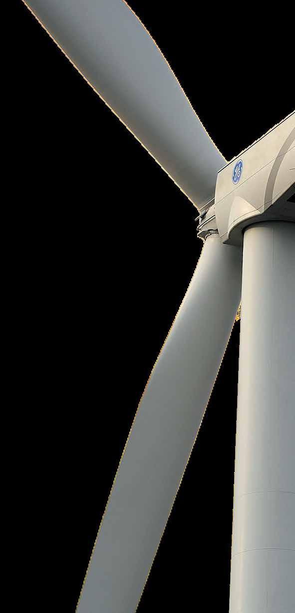
1 RISE ABOVE AW3000 ACCIONA Windpower has seen explosive growth of orders for its AW3000 platform. This success is due to a track record of reliability and product innovation coming from one of the most experienced wind energy companies in the world. The latest evolution is the AW132/3000 for low-wind sites, which delivers the lowest cost of energy in this segment. Partner with ACCIONA Windpower to make your projects rise above the competition. OPTIMIZED PERFORMANCE FOR ALL SITES Full suite of rotor options covering all wind conditions, including the AW132/3000 for lowwind sites Steel and concrete tower options with hub heights from 84 to meters Proven and bankable designs including double-bearing support on main shaft, glass fiber and epoxy blades and DFIG electrical generation BUILT BY OPERATORS FOR OPERATORS Based on a scaled design of our successful AW1500, the AW3000 provides more energy capture per wind turbine location Our track record of fleet wind turbine performance includes global average availability over 98% and extremely low failure rates of major components COMPATIBILITY & CONTROL Zero voltage ride-through beyond current regulatory requirements, in addition to grid integration and reactive power solutions to allow for maximum control for stringent grid codes Control software that allows intelligent automatic monitoring and operation SAFETY Hydraulic pitch control for safe and reliable blade pitching in all wind environments Two-person lift; hub access from inside the nacelle; and spacious, ergonomic nacelle design allow for operational efficiency 12 KV VERSUS 690 V This configuration, proven in our wind turbines, can remove the step-up transformer from the equation and is ideal for projects that are in close proximity to the substation The result is significant savings over the life of the project Up to 50% savings in collection system costs Average of 1% greater energy productions due to the avoidance of transformer electrical losses Avoidance of maintenance and potential failures of transformers AW 100/3000 AW 116/3000 AW 125/3000 AW 132/3000 AW3000 AW3000 DESIGN ADVANTAGES ) Double bearing-supported main shaft 2 ) Robust gearbox with HALT completed 3 ) 6 pole DFIG 12 kv generator 4 ) Elastic coupling 5 ) Cast hub with access from nacelle 6 ) Blades with structural shell design and proven materials including glass fiber and epoxy resin 7 ) Steel and concrete tower options from 84m to 137.5m hub heights 8 ) Yaw bearing and caliper brakes

 dynamic between +/- 5% p.u.")
 Double spherical roller")
2 MODEL AW 100/3000 AW 116/3000 AW 125/3000 AW 132/3000 Rotor diameter 100 m 116 m 125 m 132 m Wind class IEC la IEC lla IEC IIb/IIIa IEC IIIb Turbine suitability High wind sites Medium wind sites Medium wind sites Low wind sites with higher turbulence with low turbulence with low turbulence intensity intensity intensity AW3000 TECHNICAL SPECIFICATIONS OPERATING DATA Cut-in wind speed 4 m/s 3.5 m/s 3.5 m/s 3 m/s Cut-out wind speed 25 m/s 25 m/s 25 m/s 25 m/s Cold Weather Operational -30ºC to + 40ºC Temperature range (Optional) Power factor range Zero voltage ride through ROTOR +/ (1,200 kva) dynamic between +/- 5% p.u. voltage Meets or exceeds global requirements Swept area 7,854 m² 10,568 m² 12,305 m² 13,720 m² Power regulation Independent pitch regulated with variable speed DRIVE TRAIN Gearbox Bearings Lubrication PITCH SYSTEM Actuation Failsafes YAW SYSTEM Type Slewing ring Braking system GENERATOR Type Frequency Nominal voltage 3 stages: 2 planetary, 1 parallel (helical) Double spherical roller bearings Pressure and splash with oil cooler/oil filter Hydraulic cylinders Blade-independent piston accumulators on hub Four-point ball bearing, external gear External Disk+callipers, plus electro-mechanical brake per motor drive 6 poles, double feeding 50/60 Hz 12,000 V (able to eliminate step-up transformers depending on wind farm layout) TOWER Steel hub height options (m) Steel tower number of sections Concrete hub height , , 120, options (m) Concrete tower number 5 5, 6 5, 6, 7 6 of sections NACELLE Weight (tons) Dimensions Transportability 111 t (without hub) 10.9 m (length) 4.09 m (width) 4.15 m (height) Four options (split nacelle), and rail capable LIFE AND HOIST CAPACITIES Service lift capacity 250 kg Onboard crane hoist lift capacity 500 kg infowindpower@acciona.es The technical data included in this brochure may be subject to revision without prior notice. The technical data included in this brochure is not contractually binding.


3 G MW Benchmark in return for low-wind sites Gamesa maintains its unwavering commitment to continue developing the best technological solutions for its clients while reducing the cost of energy of its products as much as possible. One example is Gamesa s latest technological design unveiled for its 2.5 MW product line, the new G MW IIIA wind turbine. Intended for low-wind sites, with this new model Gamesa will provide clients with the most competitive class III product on the market in the 2 to 3 MW power capacity segment. The new G MW IIIA wind turbine, featuring a new 126-meter rotor combined with a 2.5 MW generator, is a benchmark for return in the main segment of the onshore wind power market, which is among the most competitive. The knowledge acquired through the launching of Gamesa s latest products has been a key factor in the design of this new model. With an optimized product development methodology and new testing and validation procedures, the time to market for this new turbine has been significantly reduced. Thanks to an extremely low power density, excellent capacity factor and reduced cost of energy, the G MW wind turbine has received a remarkable welcome in the sector and is destined to take its place as an industry leader alongside Gamesa s G MW wind turbine. As a matter of fact, the G MW model has recently been awarded Best Turbine Of The Year 2016 in the category of less than 3 MW by the publication Windpower Monthly. PROVEN TECHNOLOGY 20-25% MORE ENERGY PRODUCTION* EXCELLENT CAPACITY FACTOR AND REDUCED cost of energy OPTIMIZED FOR LOW-WIND SITES G MW ALSO AVAILABLE * Compared with G MW.
4 NEW MODEL G MW IIIA Gamesa harnessed the experience acquired through the installation of 26 GW of its high performance 2.0 MW platform to develop this new model, capable of generating even more power at low-wind sites while remaining as competitive as the existing models with smaller rotor. The company s most recently developed turbines thus emerge through this approach: G MW IIA/IIIA, G MW IIA, and now G MW IIIA. Following the evolutionary model of the 2.5 platform, and minimizing the risk associated with new technologies, the G MW is equipped with a 62 meter blade based on the 56-meter variant already delivering maximum production at lower noise and comprehensively validated for G114 turbines. Based on the same principle, the electrical system incorporated in the G126 is common for all 2.5 MW models. Boasting a 20% increase in power production compared to the G MW model, the G MW wind turbine rounds off Gamesa s offering for Class III sites. With this new addition, Gamesa completes its 2.5 MW product portfolio, with three different rotors, tower heights from 68 to 137 meters, and environmental options enabling installation at even the most complex sites. NOMINAL POWER INCREASE G MW General Details Blades Rated power Wind class Rotor diameter Swept area Power density Control Gearbox Generator Frequency Length Airfoil Towers Height AEP G MW vs. G MW Power (kw) % 30% 25% 20% 15% 10% 5% 0% 2.5 MW G Wind speed (m/s) G MW G MW 6,0 6,5 7,0 7,5 8,0 Average wind speed (m/s) G MW SPECIFICATIONS 2.5 MW IIIA 126 m 12,469 m W/m 2 Pitch and variable speed 3 stages Doubly fed 50Hz / 60 Hz 62 m Gamesa In order to minimize the environmental impact, this document has been printed on paper made from 50% pure cellulose fiber (ECF), 40% selected pre-consumer recycled fiber, and 10% post-consumer deinked recycled fiber inks based exclusively on vegetable oils with a minimum volatile organic compound (VOC) content. Varnish based predominantly on natural and renewable raw materials. 84, 102, 129, 137 m and site specific G MW G MW MW IIIA 126 m 12,469 m W/m 2 Pitch and variable speed 3 stages Doubly fed 50Hz / 60 Hz 62 m Gamesa G MW 84, 102, 129, 137 m and site specific swept area increase +22% AEP increase >20% The present document, its content, its annexes and/or amendments has been drawn up by Gamesa Corporación Tecnológica, S.A. for information purposes only and could be modified without prior notice. All the content of the Document is protected by intellectual and industrial property rights owned by Gamesa Corporación Tecnológica, S.A. The addressee shall not reproduce any of the information, neither totally nor partially. Printed date: January 2017 C/ Ciudad de la Innovación, Sarriguren (Spain) Tel: Fax: info@gamesacorp.com AUSTRALIA Level 39, 385 Bourke Street Melbourne VIC 3000 BRAZIL Eldorado Business Tower Av. das Nações Unidas, l 5º andar Pinheiros, São Paulo - SP Tel: CHILE Presidente Riesco 5335 Piso 9 Las Condes - Santiago Tel: +56 (2) CHINA 23/F, Tower 1, Beijing Prosper Center No. 5 Guanghua Road, Chaoyang District, Beijing Tel: Fax: EGYPT 3, Rd 218 Degla Maadi, Cairo Tel: Fax: FRANCE 97 Allée Borodine - Cedre Saint Priest Tel: +33 (0) GERMANY Röntgenstraße Hamburg Fuhlsbüttel Tel: GREECE 9 Adrianiou str, Neo Psychiko, Athens Tel: Fax: HONG KONG Asia Pacific Oceania Central Plaza, 35th Floor, 18, Harbour Road Hong Kong SAR Tel: INDIA The Futura IT Park, B-Block, 8th Floor 334, Rajiv Gandhi Salai Sholinganallur, Chennai Tel: sales.india@gamesacorp.com ITALY Via Ostiense 131/L Corpo C1 9 piano Rome Tel: Fax: Japan TOC Minatomirai Bldg. 10F, Sakuragi-cho, Naka-ku, Yokohama-shi, Kanagawa T: MEXICO Torre Mayor Paseo de la Reforma 505, piso 37 Col. Cuauhtémoc C.P , Ciudad de México Tel: Philippines 22th Floor, The Enterprise Center Tower I 1226 Ayala Avenue Makati City Philippines Tel: POLAND Ul. Galaktyczna 30A Gdansk Tel: Fax: poland.wind@gamesacorp.com ROMANIA 169A Calea Floreasca Street, Building A, 4th Floor, Office no 2069, Sector Bucarest Tel: Fax: SRI LANKA #51/1, Colombo Road, Kurana, Katunayake Tel: SWEDEN, FINLAND, NORWAY Bibilotekstorget Solna (Sweden) Tel: +46 (0) Thailand Sathom Square, 98 North Sathom Road 37/F Sathom Square Silom, Bangkok Bangkok TURKEY Astoria, Buyukdere Cad. No. 127, Kule A, Kat 10 Esentepe, Istambul Tel: UNITED KINGDOM Braidhurst House Finch Way, Strathclyde Business Park, Bellshill ML4 3PE Tel: UNITED STATES 1150 Northbrook Drive Trevose, PA Tel: Fax:


5 G MW Optimum CoE for sites with medium winds One of the keys to Gamesa s success is the constant development of new and advanced products adapted to customers needs in any type of site and with maximum profitability. With this purpose in mind the new Gamesa 3.3 MW platform has been launched with its first model: the G MW wind turbine for Class II sites. A new generation of multi-megawatt turbines that reaches the market to become the best solution in terms of Cost of Energy in the MW segment, one of the most competitive and demanding. This new platform, together with the current Gamesa 2.0 MW, Gamesa 2.5 MW and Gamesa 5.0 MW, makes the company product portfolio one of the most complete and versatile in the market and allows Gamesa to assure the best solution for customers projects. Thanks to the operative experience accumulated by Gamesa throughout more than 20 years in the wind energy market, the G MW wind turbine enables the company to guarantee the highest levels of reliability. The use of mature and proven technology available in Gamesa s current portfolio has resulted in the first G MW prototype installed in The BEST CoE in the MW segment New platform based on MATURE and PROVEN TECHNOLOGY 34% LARGER SWEPT AREA* G MW ALSO AVAILABLE * vs. G MW and G MW.

6 New G MW IIA wind turbine The G MW IIA wind turbine is integrated in the portfolio of Gamesa with a clear objective: to complement the product offer for medium-wind sites in markets where the customers require solutions with nominal powers higher than 3 MW. The G MW turbine improves on the production capacity of the models G MW and G MW, available for Class II sites, both boosting the nominal power up to 3.3 MW and increasing the rotor swept area by 34%, which makes it one of the most efficient and cost-effective solutions for medium-wind sites. With a 64.5 m fiberglass blade, optimized for Class II sites and with airfoils that have already been thoroughly tested and validated in the G MW IIA wind turbine (first prototype installed in Alaiz -Spain- in the second quarter of 2015), the new model G MW guarantees maximum energy production and low noise emission levels, with maximum theoretical value for this turbine fixed at dba. Gamesa incorporates proven technology into this model, such as the combination of a three-stage gearbox (two planetary stages and one parallel) and a doubly-fed induction generator, the same solution used in the Gamesa 2.0 MW platform, which has 26 GW installed worldwide. The G MW wind turbine also has an extensive portfolio of towers with heights ranging from 84 m to 154 m, which enables it to comply with the different maximum blade tip height restrictions in certain markets. NOMINAL POWER INCREASE swept area increase General Details Blades Rated power Wind class Rotor diameter Swept area Power density Control Gearbox Generator Frequency Length Airfoil Towers G114 Height 3.3 MW 2.5 MW 2.0 MW G % G MW SPECIFICATIONS 3.3 MW IIA 132 m 13,685 m W/m 2 Pitch and variable speed 3 stages Doubly fed 50 Hz / 60 Hz 64.5 m Gamesa In order to minimize the environmental impact, this document has been printed on paper made from 50% pure cellulose fiber (ECF), 40% selected pre-consumer recycled fiber, and 10% post-consumer deinked recycled fiber inks based exclusively on vegetable oils with a minimum volatile organic compound (VOC) content. Varnish based predominantly on natural and renewable raw materials. Power (kw) AEP G MW vs. G MW & G MW AEP increase 70% 60% 50% 40% 30% 20% 10% 0% 84, 97, 114, 134, 154 m and site specific Wind speed (m/s) G MW G MW G MW 7,0 7,5 8,0 8,5 9,0 Average wind speed (m/s) G MW vs. G MW G MW vs. G MW G MW MW IIA 132 m 13,685 m W/m 2 Pitch and variable speed 3 stages Doubly fed 50 Hz / 60 Hz 64.5 m Gamesa 84, 97, 114, 134, 154 m and site specific The present document, its content, its annexes and/or amendments has been drawn up by Gamesa Corporación Tecnológica, S.A. for information purposes only and could be modified without prior notice. All the content of the Document is protected by intellectual and industrial property rights owned by Gamesa Corporación Tecnológica, S.A. The addressee shall not reproduce any of the information, neither totally nor partially. Printed date: January 2017 C/ Ciudad de la Innovación, Sarriguren (Spain) Tel: Fax: info@gamesacorp.com AUSTRALIA Level 39, 385 Bourke Street Melbourne VIC 3000 BRAZIL Eldorado Business Tower Av. das Nações Unidas, l 5º andar Pinheiros, São Paulo - SP Tel: CHILE Presidente Riesco 5335 Piso 9 Las Condes - Santiago Tel: +56 (2) CHINA 23/F, Tower 1, Beijing Prosper Center No. 5 Guanghua Road, Chaoyang District, Beijing Tel: Fax: EGYPT 3, Rd 218 Degla Maadi, Cairo Tel: Fax: FRANCE 97 Allée Borodine - Cedre Saint Priest Tel: +33 (0) GERMANY Röntgenstraße Hamburg Fuhlsbüttel Tel: GREECE 9 Adrianiou str, Neo Psychiko, Athens Tel: Fax: HONG KONG Asia Pacific Oceania Central Plaza, 35th Floor, 18, Harbour Road Hong Kong SAR Tel: INDIA The Futura IT Park, B-Block, 8th Floor 334, Rajiv Gandhi Salai Sholinganallur, Chennai Tel: sales.india@gamesacorp.com ITALY Via Ostiense 131/L Corpo C1 9 piano Rome Tel: Fax: Japan TOC Minatomirai Bldg. 10F, Sakuragi-cho, Naka-ku, Yokohama-shi, Kanagawa T: MEXICO Torre Mayor Paseo de la Reforma 505, piso 37 Col. Cuauhtémoc C.P , Ciudad de México Tel: Philippines 22th Floor, The Enterprise Center Tower I 1226 Ayala Avenue Makati City Philippines Tel: POLAND Ul. Galaktyczna 30A Gdansk Tel: Fax: poland.wind@gamesacorp.com ROMANIA 169A Calea Floreasca Street, Building A, 4th Floor, Office no 2069, Sector Bucarest Tel: Fax: SRI LANKA #51/1, Colombo Road, Kurana, Katunayake Tel: SWEDEN, FINLAND, NORWAY Bibilotekstorget Solna (Sweden) Tel: +46 (0) Thailand Sathom Square, 98 North Sathom Road 37/F Sathom Square Silom, Bangkok Bangkok TURKEY Astoria, Buyukdere Cad. No. 127, Kule A, Kat 10 Esentepe, Istambul Tel: UNITED KINGDOM Braidhurst House Finch Way, Strathclyde Business Park, Bellshill ML4 3PE Tel: UNITED STATES 1150 Northbrook Drive Trevose, PA Tel: Fax:


7 GE Renewable Energy GE s 3 MW Platform POWERFUL AND EFFICIENT
8 GE S 3 MW PLATFORM PITCH Since entering the wind industry in 2002, GE Renewable Energy has invested more CONTROLS than $2 billion in next-generation wind turbine technology to provide more value to customers whether at the turbine, plant or grid level. Through the use of advanced analytics, GE Renewable Energy is redefining the future of wind power, delivering with proven performance, availability and reliability. With the integration of big data and the industrial internet, we can help customers manage the variability that comes with this resource WIND POWER DOMAIN Predix for smooth, predictable power. Our onshore product portfolio includes wind turbines with rated capacities from MW BIG DATA and flexible support services that range from basic operations and maintenance to farm- or fleet-level enhancements. For more information visit our website: ONITORING SOFTWARE CoE

9 POWERFUL AND EFFICIENT GE s 3 MW Platform Extending the capability of the Digital Wind Farm to our 3 MW machines, GE s powerful and efficient platform is adaptable to a full spectrum of wind regimes. The platform includes the , our highest performing turbine for Class III winds. GE has employed selected legacy components with proven performance for the 3 MW platform, helping to ensure the consistent performance and reliability for which GE wind turbines are known. Turbine models within the 3 MW platform share drivetrain and electrical system architecture, with both systems scaled and upgraded for improved performance and greater energy production, as compared to previous models. Parameters of the 3MW Platform GE s 3MW platform can be customized based on nameplate, rotor diameter and hub height. 3
10 GE S MW PLATFORM Building Upon Proven Technology Model introduction in Europe MW Platform Built from the maturity of its predecessors, the 3 MW platform increases the capacity factor, annual energy production (AEP) and application space. Component enhancements to the 2.5 MW models have resulted in a substantial performance increase, enabling the use of a 130- and 137- meter rotor on the 3 MW series and a nameplate ranging from MW. These enhancements include gearbox and controls improvements, and a new aerodynamic structure enabling a greater blade length ( meter rotor). Crafted for high reliability, GE s 3 MW platform offers excellent availability that is comparable to the 2.5 MW series units operating in the field today. Technical Description GE s 3 MW platform machines are three-blade, upwind, horizontal axis wind turbines with a rotor diameter ranging from 130 to 137 meters. The turbine rotor and nacelle are mounted on top of a tubular steel tower, with a range of hub height options that includes 85-, 110-, , 134- and meter variants. The turbines use active yaw control to keep the blades pointed into the wind. The 3 MW platform is engineered to operate at variable speeds and uses a doubly fed asynchronous generator with a partial power converter system. 4
11 POWERFUL AND EFFICIENT Specifications 3 MW platform Standard and cold weather extreme options Standard tower corrosion protection: C2 internal and C3 external with internal and external C4/C5 options available Rotational direction: Clockwise viewed from an upwind location Speed regulation: Electric drive pitch control with battery backup Aerodynamic brake: Full feathering of blade pitch GE s IEC 2B/3A Up to 20% higher output than GE s Improved load management system and more efficient drive train technology Same electrical system as turbine Sound power level of 106 db(a), reduced noise modes available Tip heights include 150 m, 175 m, and 199 m rotor GE s IEC2B Up to 30% higher output than GE s Increased electrical rating of 3.4 MW combined with 130-meter rotor db(a) normal operation sound power level, reduced noise modes available Tip heights include 150 m, 175 m, 199 m, and 233 m GE s IEC3B Up to 28% higher output than GE s New blade for more efficient production in low wind conditions Sound power level of 106 db(a), reduced noise modes available Tip heights include m, 199 m, and 223 m 5
12 GE S 3 MW PLATFORM Features and Benefits Engineered to meet or exceed the 2.5 MW platform s historic high availability Available grid-friendly options: Enhanced Reactive Power, Low & Zero Voltage Ride Thru, Power Factor Control, WindFreeReactive Power Wind Farm Control System; WindSCADA* Available in both 50 Hz and 60 Hz versions Construction Towers: Tubular steel sections provide a hub height of 85 m, 110 m, and 131 m Hybrid pre-cast concrete/tubular steel towers for multiple hub heights Logistic friendly tower for a hub height of 85 m, 110 m, and 131 m Blades: 63.7-meter blades (130-meter rotor); 67.2-meter blades (137-meter rotor) Drivetrain components: GE s 3 MW platform uses an enhanced gearbox, main shaft with double bearings, and generator with appropriate improvements to enable the 130- and 137-meter diameter rotor in medium and lower wind speeds. Enhanced Controls Technology The 3 MW platform uses enhanced controls features: GE s patented Advanced Loads Control reduces loads on turbine components by measuring stresses and individually adjusting blade pitch. Controls were developed by GE Global Research to reduce extreme loads, including those near rated wind speeds, to improve annual energy production (AEP). Condition Monitoring System GE s Condition Monitoring System (CMS) and SCADA Anomaly Detection Services, a complementary suite of advanced condition monitoring solutions, proactively detects impending drive train and whole-turbine issues, enabling increased availability and decreased maintenance expenses. Built upon half a century of power generation drivetrain and data anomaly monitoring experience, this service solution is now standard on GE s 3 MW platform. 6


13 POWERFUL AND EFFICIENT 7
14 YAW TORQUE MAKING RENEWABLES THE ENERGY OF CHOICE FOR A CLEANER FUTURE DIGITAL WIND FARM WindSCADA DUSTRIAL INTERNET CONNECTED MACHINES *Trademark of General Electric Company Copyright 2016 General Electric Company. All rights reserved. GEA32208 (09/2016)


15 DELTA GENERATION PROVEN TECHNOLOGY AT A NEW STAGE OF EVOLUTION N100/3300 N117/3000 N131/3000

16 02 Delta Generation CONTENTS 03 TECHNICAL DEVELOPMENT AT NORDEX Experience keeps us one step ahead 04 MATURE TECHNOLOGY Proven concepts ensure a secure investment 06 ECONOMIC EFFICIENCY Higher yields reduce the cost of energy 08 QUALITY AND RELIABILITY A focus on high availability 10 SERVICE AND HSE Fast and safe turbine O&M 12 DELTA GENERATION IN THE FIELD First turbines installed and certified 14 SOLUTION FOR STRONG WIND High yields in a rough climate 16 SOLUTION FOR MODERATE WIND Economical at a wide range of sites 18 SOLUTION FOR LIGHT WIND Maximum efficiency in the 3 MW segment
17 Delta Generation 03 TECHNICAL DEVELOPMENT AT NORDEX Experience keeps us one step ahead As one of the pioneers in the modern use of wind energy, Nordex has been developing increasingly efficient wind turbines for use onshore since Since then, we have always remained true to proven principles, using tried-and-tested series engineering and giving top priority to the reliability of all system components. In 2000, Nordex installed the first 2.5 megawatt series turbine in the world. Since then, the company has connected more than 4,000 machines from this platform to the grid at a wide range of locations around the world. We know what we re talking about when we claim that our wind turbine generators offer quality, mature technology and dependable performance, even in extreme locations. With Delta Generation, we are now offering the fourth turbine generation of our proven multi-megawatt platform. Thanks to its larger rotors, greater nominal capacity and optimised technical systems, Delta Generation sets new standards for economic efficiency, reliability and service- and HSE-friendliness.

18 04 Delta Generation MATURE TECHNOLOGY Proven concepts ensure a secure investment With the new Delta Generation, Nordex customers benefit from the know-how we have gathered in the multi-megawatt range over many years. Mature technical solutions that have proven their worth thousands of times form a sound basis for the new generation. Continuity: The electrical system Even the first Nordex multi-megawatt turbine was equipped with a doubly fed asynchronous generator and a partial converter. With Delta Generation, we have maintained this proven and highly economical electrical system. Tried-and-tested drive train concept The drive train system is based on a modular drive train layout with a three-point suspension. We have used this system successfully from the outset. Together with our qualified suppliers, we work on continuously improving our drive train components. This delivers the output required while maintaining availability at a high level. Proven rotor blade designs The turbines of the new generation use proven aerodynamic designs for the rotor diameters of 100 and 117 metres. Nordex developed the NR50, NR58.5 and NR65.5 blades in-house. This allowed us to realise an optimal concept for the overall turbine system. The efficient rotor blades match the respective turbine technology perfectly. The fourth generation of the Nordex multi-megawatt platform combines proven, dependable technology with targeted improvements for enhanced performance.
.")
19 Delta Generation 05 Grid compatibility ensured Like the previous generations, the turbines of Delta Generation meet the grid requirements of international markets. One of the most demanding grid connection directives in Europe is the German SDLWindV (Ordinance on System Services by Wind Energy Plants). Thanks to their fault-ride-through capability, our turbines are able to bridge voltage drops easily, thereby meeting all the requirements for the System Service Bonus (SDL Bonus). In addition, the Nordex Wind Farm Management System also allows the grid operator to directly control the active and reactive power of the wind farm in the grid. Making the most of cold locations During the winter, temperatures can be extreme at many sites offering a high wind yield. The tried-and-tested Nordex coldclimate package is designed to meet the challenges of these especially cold locations. Turbines in the cold-climate version (CCV) are able to operate down to an outside temperature of -30 degrees Celsius.

20 06 Delta Generation ECONOMIC EFFICIENCY Higher yields reduce the cost of energy In developing Delta Generation, we have met our main target to cut the cost of energy. These Nordex multi-megawatt turbines deliver up to 31 per cent more yield from the sites, making Delta Generation turbines a particularly worthwhile investment. Larger: Rotors Nordex has designed the turbines to use a much larger rotor for each wind class. This produces higher yields. For example, the rotor diameter for machines for strong-wind locations was increased by ten metres compared to the previous model, resulting in a 23 per cent increase in swept area. The rotor for sites with moderate wind speeds is 17 metres larger: a 37 per cent increase in rotor sweep. With its 14 metre larger diameter, the rotor for light-wind sites offers a 25 per cent increase in swept area.

21 Delta Generation 07 Stronger: Rated Output With the N100/3300, Nordex has raised the rated output of the strong wind turbine by more than 30 per cent. The N117/3000 is designed for moderate wind speeds and has a 20 per cent higher rated output than the previous model. The increase in rated output amounts to 25 per cent for the N131/3000 light-wind turbine. This has a positive effect on the energy yields of the Delta turbines. In spite of the considerable increase in output, the sound power levels remain stable for each class. With the N131/3000, Nordex has further reduced the sound power level of the turbine for light-wind sites. Higher: Towers New and higher hub heights produce even greater yield increases and make siting possible, even in wooded areas or locations with complex topography. For the first time, Nordex is offering a tubular steel tower with a hub height of 100 metres for strong wind locations and one with a hub height of 120 metres for sites with moderate wind speeds. Smarter: Anti-Icing Systems Particularly in frost regions, ice forms on rotor blades in the winter months. Icing can reduce the efficiency of a wind turbine generator as well as lowering its availability. The proven Nordex anti-icing system heats the most aerodynamically important areas of the rotor blades and efficiently reduces icing levels. Nordex customers can rely on their turbines for dependable yields and maximum availability in cold regions.

22 08 Delta Generation QUALITY AND RELIABILITY A focus on high availability To ensure that our turbines perform reliably, we conduct exhaustive tests. We certify the quality of all components and manufacture in a modern line production. The average availability of all turbines covered by Nordex Service stands at 98 per cent. We ensure this high level of availability by consistently further developing the vital important systems. This contributes to a further reduction in the cost of energy. Extreme tests for hardware and software In the Nordex Test Centre, engineers test the components and systems of the new turbine generation under simulated wind and weather conditions. By subjecting them to strains in excess of the usual specifications, Nordex ensures that the design meets all criteria, delivering a high-quality, mature product for serial production. Highest industrial standards Nordex continues to meet high industrial standards, manufacturing the nacelle and hub modules in a continuous flow process. Many of the steps needed for assembly and commissioning are performed in the protected factory hall before the equipment is shipped to the site. In the Nordex Test Centre engineers ensure the quality of components.

23 Delta Generation 09 Advanced control infrastructure Nordex has equipped the new turbine generation with the Profinet communication system. Its ethernet-based fieldbus transfers turbine data rapidly, reliably and by priority. All actuators and sensors in the turbine control systems, as well as the different module options, are directly integrated into the network. This ensures improved diagnostics and the reliability of the system. Optimised drive train The drive train design of Delta Generation reduces the forces acting on the individual components, taking greater strain off the robust rotor bearing. Innovations in the cooling system of the drive train ensure constant temperatures over a wide operating range with lower internal energy consumption.

24 10 Delta Generation SERVICE AND HSE Fast and safe turbine O&M Delta Generation is designed so that service operations can be conducted rapidly and safely. This reduces ongoing operational costs. We make no compromise when it comes to HSE the turbines of the new generation meet the most stringent requirements. Protected hub access The new spinner, a complete housing for the rotor hub, provides rapid and protected access to the hub. This means that service work can be carried out in a wider range of wind and weather conditions. This is of particular advantage in cold regions making it possible to reduce downtimes for service purposes. The arrow indicates the protected hub access via the spinner.

25 Delta Generation 11 Ergonomics and safety When we were developing the new multi-megawatt generation, we gave high priority to designing the turbines as a particularly safe and spacious workplace. In case of an emergency, the platform also offers extended escape and rescue routes. All systems are easily accessible for maintenance. Nacelle components weighing less than one tonne can be reached with the onboard crane and, if necessary, can be exchanged without additional equipment. Annual service interval The technical design of Delta Generation allows for an annual service interval. Automatic lubrication of the bearings in the pitch system replaces manual processes. These bearings, as well as the main bearing and the generator bearings, are supplied automatically with lubricant, making them less susceptible to wear. This minimises the service requirements and reduces the O&M expenses. Yaw n-1 concept The yaw system runs with four drives in standard operation. However, should one drive break down, the turbine can continue to run temporarily on three drives, making it possible to plan any needed service work. This concept increases turbine availability and reduces service costs.

26 12 Delta Generation DELTA GENERATION IN THE FIELD Tried-and-tested performance In mid-2013, Nordex installed the first Delta Generation turbines for high and medium wind speeds in the Janneby wind farm in Germany. By now, the family has a new member the light wind model N131/3000 has been installed and commissioned in the same wind farm. Certification and field validation are running on schedule: all DIBt type approvals and the International IEC Design Evaluation Conformity Statements (DECS) have been obtained for the Delta Generation turbines. The IEC Type Certificate (TC) has been awarded for N100/3300 and N117/3000. The principal measurement results for all types were recorded at the Janneby site. Particularly important: the sound power levels of the three turbines were confirmed by external measurements. The german unit certificates as well the power curves have already been issued for the N117/3000 and the N100/3300.

27 Delta Generation 13
28 14 Delta Generation SOLUTION FOR STRONG WIND High yields in rough climates Wind sites with a rough environment call for mature, robust technology. With the turbines of Delta Generation, Nordex offers the proven 100-metre rotor, now also for IEC 1 locations. Thanks to the large rotor diameter and the higher rated output, the N100/3300 obtains much higher energy yields at sites with strong winds compared to the previous model. This turbine is available with hub heights of 75, 85 and 100 metres. The N100/3300 generates between 21.2 and 31.4 per cent more AEP compared to the preceding IEC 1 model. AEP in per cent compared to N90/2500-R % 30.0 % 31.4 % 31.3 % 31.1 % 30.9 % N100/3300 on a hub height of 100 m 20.0 % 10.0 % 21.2 % 22.1 % 22.9 % 23.7 % N100/3300 on a hub height of 75 m 0.0 % 8.5 m/s 9.0 m/s 9.5 m/s 10.0 m/s Wind speed at 80 m Calculation of AEP based on air density of kg/m³, wind shear of 0.2 and Weibull shape parameter of k = 2.0
29 Delta Generation 15 TECHNICAL DATA N100/3300 Operating data Rated power Cut-in wind speed Cut-out wind speed 3,300 kw 3.5 m/s 25 m/s Rotor Diameter 99.8 m Swept area 7,823 m² Operating range rotational speed rpm Rated rotational speed 14.3 rpm Tip speed 75 m/s Speed control Variable via microprocessor Overspeed control Pitch angle Gearbox Type Generator Construction Cooling system Voltage Grid frequency Brake system Main brake Holding brake 3-stage gearbox (planetary-planetary-spur gear) Doubly-fed asynchronous generator Liquid / air cooling 660 V 50 / 60 Hz Aerodynamic brake (Pitch) Disk brake Lightning protection Fully compliant with IEC Tower Construction Hub height/certification Tubular steel tower 75 m / IEC 1a, DIBt 3 85 m / IEC 1a 100 m / IEC 1a, DIBt 3 The powerful N100/3300 is the first choice for strong wind sites.
30 16 Delta Generation SOLUTION FOR MODERATE WIND Economical at a wide range of sites With the N117/3000, Nordex now offers an even more economical turbine for IEC 2 locations. The enlarged rotor sweep and higher rated output deliver much higher yields. The N117/3000 is available on tubular steel towers of 91 or 120 metres, as well as on a hybrid tower of 141 metres. Therefore, it is suitable for challenging sites as well. To ensure high yields at sites in cold climates, Nordex equips the N117/3000 with the efficient anti-icing system as an option. The N117/3000 generates between 21.7 and 33.6 per cent more AEP compared to the preceding IEC 2 model. AEP in per cent compared to N100/2500-R % 30.0 % 20.0 % 10.0 % 33.6 % 32.1 % 30.8 % 29.7 % 22.4 % 22.1 % 21.9 % 21.7 % N117/3000 on a hub height of 120 m N117/3000 on a hub height of 91 m 0.0 % 7.0 m/s 7.5 m/s 8.0 m/s 8.5 m/s Wind speed at 100 m Calculation of AEP based on air density of kg/m³, wind shear of 0.2 and Weibull shape parameter of k = 2.0

31 Delta Generation 17 TECHNICAL DATA N117/3000 Operating data Rated power Cut-in wind speed Cut-out wind speed 3,000 kw 3.0 m/s 25 m/s Rotor Diameter m Swept area 10,715 m² Operating range rotational speed rpm Rated rotational speed 12.6 rpm Tip speed 77 m/s Speed control Variable via microprocessor Overspeed control Pitch angle The N117/3000 economical at a wide range of sites. Gearbox Type Generator Construction Cooling system Voltage Grid frequency Brake system Main brake Holding brake 3-stage gearbox (planetary-planetary-spur gear) Doubly-fed asynchronous generator Liquid / air cooling 660 V 50 / 60 Hz Aerodynamic brake (Pitch) Disk brake Lightning protection Fully compliant with IEC Tower Construction Tubular steel tower Hybridtower Hub height/certification 91 m / IEC 2a, DIBt m / IEC 2a, DIBt m, DIBt 2
32 18 Delta Generation SOLUTION FOR LIGHT WIND Maximum efficiency in the 3 MW segment High yield even in regions with light wind: thanks to its enlarged rotor sweep and higher rated output, the N131/3000 generates a much higher yield at light-wind locations. The turbine is available on tubular steel towers with hub heights of 99 or 114 metres. Nordex limits the sound power level of the light-wind turbine to max db(a) a crucial factor for optimising wind farms and facilitating permitting. To ensure high yields at sites in cold climates, Nordex equips the N131/3000 with the efficient anti-icing system as an option. The N131/3000 generates between 27.4 and 28.6 per cent more AEP compared to the preceding IEC3 model. AEP in per cent compared to N117/2400-R % 30.0 % 20.0 % 10.0 % 28.6 % 28.2 % 27.8 % 27.4 % 21.1 % 21.8 % 22.1 % 22.4 % N131/3000 on a hub height of 99 m Comparison based on identical hub height 0.0 % 6.0 m/s 6.5 m/s 7.0 m/s 7.5 m/s Wind speed at 91 m Calculation of AEP based on air density of kg/m³, wind shear of 0.2 and Weibull shape parameter of k = 2.0
33 Delta Generation 19 TECHNICAL DATA N131/3000 Operating data Rated power Cut-in wind speed Cut-out wind speed 3,000 kw 3.0 m/s 20 m/s Rotor Diameter m Swept area 13,478 m² Operating range rotational speed rpm Rated rotational speed 10.3 rpm Tip speed 70.5 m/s Speed control Variable via microprocessor Overspeed control Pitch angle Gearbox Type Generator Construction Cooling system Voltage Grid frequency Brake system Main brake Holding brake 3-stage gearbox (planetary-planetary-spur gear) Doubly-fed asynchronous generator Liquid / air cooling 660 V 50 / 60 Hz Aerodynamic brake (Pitch) Disk brake Lightning protection Fully compliant with IEC Tower Construction Hub height/certification Tubular steel tower 99 m / IEC 3a, DIBt m / IEC 3a, DIBt 2 Strong, efficient and quiet: the N131/3000.
34 WORLDWIDE OFFICES and subsidiaries: Nordex SE Langenhorner Chaussee Hamburg, Germany Phone: Service Area Germany Nordex Energy GmbH Langenhorner Chaussee Hamburg, Germany Phone: Asia Nordex China Room 808, First Shanghai Center, No. 39 Liangmaqiao Road, Chaoyang District Beijing , China Phone: Benelux Nordex Energy GmbH Marconiweg XM Joure, the Netherlands Phone: Chile Nordex Chile SpA Av. Presidente Riesco 5335, Piso 9, Las Condes, Santiago, Chile Phone: Saleslatam@nordex-online.com Denmark, Baltic countries Nordex Energy GmbH Niels Bohrs Vej 12 b 6000 Kolding, Denmark Phone: SalesDenmark@nordex-online.com Finland Nordex Energy GmbH Hiilikatu Helsinki, Finland Phone: SalesFinland@nordex-online.com France Nordex France S.A.S. 1, Rue de la Procession La Plaine Saint-Denis, France Phone: SalesFrance@nordex-online.com Germany Nordex Energy GmbH Centroallee 263 a Oberhausen, Germany Phone: SalesGermany@nordex-online.com Ireland Nordex Energy Ireland Ltd. Clonmel House, Forster Way Swords, Co. Dublin, Ireland Phone: SalesIreland@nordex-online.com Italy Nordex Italia S.r.l. Viale Città d Europa Rome, Italy Phone: SalesItaly@nordex-online.com Norway Nordex Energy GmbH Regus Business Centre Karenslyst Allé 8b, 3rd floor 0278 Oslo, Norway Phone: SalesNorway@nordex-online.com Pakistan Nordex Pakistan Private Ltd. 187 Gomal Road, E-7 Islamabad 44000, Pakistan Phone: SalesPakistan@nordex-online.com Poland Nordex Polska Sp. z o.o. Ul. Puławska 182, 6th floor Warschau, Poland Phone: SalesPoland@nordex-online.com Portugal Nordex Energy GmbH Sucursal em Portugal Rua Eng.º- Ferreira Dias, n.º- 728 Edifício ANF Porto, Fracção Porto, Portugal Phone: SalesPortugal@nordex-online.com Romania Nordex Energy Romania S.R.L. Strada CA Rosetti nr 17 Etaj 7, birou 703, sector Bukarest, Romania Phone: SalesRomania@nordex-online.com Spain Nordex Energy Ibérica S. A. Pso. de la Castellana, 23 2º-a Madrid, Spain Phone: SalesSpain@nordex-online.com South Africa Nordex Energy South Africa (RF) (Pty) Ltd. Wembley Square 3, 2nd Floor 80 McKenzie Street Gardens, Cape Town 8001, South Africa Phone: SalesSA@nordex-online.com Sweden Nordex Sverige AB Kungsängsvägen 25 b Uppsala, Sweden Phone: SalesSweden@nordex-online.com Turkey Nordex Enerji A.Ş. Havaalanı Kavşağı EGS Business Park Blokları B1 Blok Kat: 15 No: Yeşilköy, Istanbul, Turkey Phone: SalesTurkey@nordex-online.com UK Nordex UK Ltd. Suite 4, Egerton House The Towers Business Park, Wilmslow Road Didsbury M20 2DX, UK Phone: SalesUK@nordex-online.com Uruguay Nordex Energy Uruguay S.A. Rizal 3555, Piso 2 CP Montevideo, Uruguay Phone: saleslatam@nordex-online.com USA, North America Nordex USA, Inc. 300 South Wacker Drive, Suite 1500 Chicago, Illinois 60606, USA Phone: SalesUSA@nordex-online.com Rest of the World Nordex Energy GmbH Langenhorner Chaussee Hamburg, Germany Phone: info@nordex-online.com Nordex All rights reserved. The contents of this document are for informational purposes only and may be subject to change without notice. No representation or warranty, whether expressed or implied, is given or should be relied upon as to the adequacy and accuracy of the information contained herein. Reproduction, use or disclosure to third parties, without our written consent, is not permitted. As of: 09/2015
 Cut-in wind speed 3 m/s Nominal wind speed 12 m/s Cut-out wind speed 22 m/s Operating temperature range -20 +40 C Certification Hub height Wind class")
35 Powered by TCPDF ( Date Design data Nominal power 3,400 kw (LV-side) Cut-in wind speed 3 m/s Nominal wind speed 12 m/s Cut-out wind speed 22 m/s Operating temperature range C Certification Hub height Wind class DIBt Wind zone m IEC S (based on IEC IIA) WZ 4, GK II m IEC S (based on IEC IIIA) WZ 3, GK II m IEC S (based on IEC IIIA) WZ 3, GK II Rotor Diameter 122 m Rotor area 11,690 m² Rotor speed /min (+15 %) Power control Electrical pitch Weight Rotor blade Nacelle without drive train Rotor Hub Electrical system Nominal power Nominal voltage Nominal frequency Generator Approx. 15 t Approx. 46 t Approx. 26 t 3,400 kw (LV-side) 10/20/30 kv 50 Hz Induction generator (squirrel cage rotor) Generator protection class IP 54 Stator voltage 580 V Speed range 735 1,356 1/min Converter type Full converter with DC intermediate circuit Transformer Internal Transformer (ITS) Sound power level Maximum sound power level db (A) Rotor blade Blade length Type Max. chord width 59.8 m Glass fibre-reinforced plastic (GFRP) 3.9 m Power curve Gear system Type Three-stage planetary / spur gearbox Gear ratio i = approx. 127 Type of suspension Three-point contact suspension Senvion GmbH Überseering Hamburg T info@senvion.com senvion.com Published by and copyright 2016 Senvion GmbH. All rights reserved. This document is for information purposes only and subject to change at any time. No guarantees are given. All obligations arise from a corresponding contract. Reproduction, use or distribution without prior written permission from Senvion GmbH is prohibited. Status 2016.
 WZ 3, GK II 127 130 m IEC IIIA WZ 2, GK II")
 Power control Electrical pitch Electrical system Nominal power Nominal voltage Nominal frequency Generator 3,600 kw (LV-side) 600 V 50 Hz Induction generator (squirrel cage rotor)")
36 Powered by TCPDF ( Date Design data Nominal power 3,600 kw (LV-side) Cut-in wind speed 3 m/s Nominal wind speed 11.5 m/s Cut-out wind speed 22 m/s Operating temperature range C Certification Hub height Wind class DIBt Wind zone m IEC S (based on IEC IIB) WZ 3, GK II m IEC IIIA WZ 2, GK II m IEC IIIA WZ 2, GK II Rotor Diameter 140 m Rotor area 15,394 m² Rotor speed /min (+25 %) Power control Electrical pitch Electrical system Nominal power Nominal voltage Nominal frequency Generator 3,600 kw (LV-side) 600 V 50 Hz Induction generator (squirrel cage rotor) Generator protection class IP 54 Converter type Full converter with DC intermediate circuit Transformer Internal Transformer (ITS) Sound power level Maximum sound power level Power curve 104 db (A) Rotor blade Blade length Type Max. chord width Gear system Type Type of suspension 68.5 m Glass fibre-reinforced plastic (GFRP) 4 m Three-stage planetary / spur gearbox Three-point contact suspension Senvion GmbH Überseering Hamburg T info@senvion.com senvion.com Published by and copyright 2016 Senvion GmbH. All rights reserved. This document is for information purposes only and subject to change at any time. No guarantees are given. All obligations arise from a corresponding contract. Reproduction, use or distribution without prior written permission from Senvion GmbH is prohibited. Status 2016.

37 Greater returns. Greater reason to celebrate. Introducing the SWT siemens.com/wind

38 SWT Greater returns. Greater reason to celebrate. High capacity factor for higher returns Witness the evolution of our robust Onshore Geared platform: Designed with the high capacity factor needs of the market in mind, Siemens powerful SWT is tailored to optimize the output of medium wind sites. The SWT builds on the foundation of Siemens proven Onshore Geared product platform, one of the most robust and successful turbine lines of all time with over 8,900 units installed globally. The turbine continues its strong heritage while scaling and streamlining innovative features to deliver an exceptional capacity factor and lower cost of energy for medium wind conditions. The MW rating and the 120 m rotor diameter result in a rotor to generator ratio that extracts more from the available wind. Due to the turbine s robust design, that high capacity factor can be used in medium wind sites for a dramatic improvement in the cost of energy. Evolved technology with a proven track record As the end-product of three decades of practical experience in the onshore wind industry, the SWT stands as the pinnacle of onshore turbine technology. Design reliability is ensured through detailed component and system testing as well as complete turbine testing and certification. By incorporating extensive operational data and advanced design tools into the development process, the SWT is able to deliver increased availability for medium wind sites all over the world. The SWT wind turbine employs a high-performance 120-meter rotor, with 59-meter, aeroelastically tailored blades. The turbine utilizes Siemens IntegralBlade technology to make intelligent use of the flexing capabilities of the blade structure. The technology allows for the SWT s larger rotor diameter and 23 percent greater swept area at reduced structural loads. The nacelle is ergonomically optimized for maintenance through increased accessibility of components and enclosed by a square steel canopy. 1 Square canopy made of steel 2 Efficient electric drive yaw motors Gearbox with one helical and two planetary stages for increased capacity Large hatches and additional space for easy access to and service of the generator and gearbox 5 Efficient cooling system for maximum reliability 5 Features designed for enhanced capacity and simplified maintenance 2
39 Greater returns. Greater reason to celebrate. SWT The SWT at a glance To increase energy production and deliver a high capacity factor and reduced cost of energy for medium wind sites, we have refined certain key features of our proven Onshore Geared product platform: 59-meter long aeroelastically tailored blades for reduced structural loading 120-meter rotor diameter with 23 percent increased swept area for a high capacity factor and enhanced energy production Gearbox and yaw system designed for greater capacity Enhanced canopy design for easier access to main components Tailoring service to your specific needs To sustain your investment, our service team will fashion an intelligent service solution designed to deliver reliability and maximum output. The ultimate goal: optimizing your return on investment throughout the lifetime of your project. Servicing your wind power plants requires dedication and a long-term partnership with a commitment to care. By tailoring our flexible range of solutions to your specific needs, we can deliver 360 asset care for the lifetime of each turbine. When action is needed, we call on our unique diagnostic capabilities and experience to respond smarter and quicker. We re equally committed to safety. Continual training and a Zero Harm policy make health and safety paramount at all times. AEP [MWh] 15,000 12,000 Swept area 11,310 m 2 9,000 6,000 3, Annual average wind speed [m/s] 120 meters Higher AEP for medium wind sites Power [kw] 3,000 1,200 2,500 1,000 2, k = 2.5 1, Wind distribution (k) 1, k = Wind speed [m/s] mean wind speed 8.5 m/s SWT / SWT IEC Class Nominal power Rotor diameter Blade length IIB / IIS 2,500 kw (SWT ) 2,625 kw (SWT ) 120 m 59 m Swept area 11,310 m 2 Hub height Power regulation Annual output at 8.5 m/s 85.1 m Pitch regulated, variable speed 13 GWh Weibull shape parameter k and power curve 3
 Email: support.energy@siemens.com Article-No. WPON-B10009-03-7600 RS1501345BR1116 All rights reserved.")
40 Published by Siemens Wind Power GmbH & Co. KG Beim Strohhause Hamburg, Germany siemens.com/wind For more information, please contact our Customer Support Center. Phone: Fax: (Charges depending on provider) Article-No. WPON-B RS BR1116 All rights reserved. Trademarks mentioned in this document are the property of Siemens, its affiliates, or their respective owners. Subject to changes and errors. The information given in this document only contains general descriptions and/or performance features which may not always specifically reflect those described, or which may undergo modification in the course of further development of the products. The requested performance features are binding only when they are expressly agreed upon in the concluded contract.

41 The Onshore Direct Drive platform your solution for every situation Picture a turbine that offers maximized performance for your unique wind site under any conditions. siemens.com/wind

42 There is a reason why customers continue to rely on Siemens. Because for 30 years, the world has experienced the innovation and risk mitigation that has established Siemens as one of the leading global supplier of onshore wind power solutions. Returns are secured through the utilization of experience, industry insight, and proven wind turbine technology. The Onshore Direct Drive platform is a prime example of this, a range of turbines flexible in performance and ability to harvest the potential of your unique site and conditions. It combines advanced site engineering with intelligent software to enable real-time, enhanced power optimization. The only constant is the need for adaptability.
43 Offering the Complete Portfolio Whatever your site s wind class, the Onshore Direct Drive platform has you covered. Swept area Swept area Swept area 15,829 m 2 13,300 m 2 13,300 m meters 130 meters 130 meters SWT IEC Class Nominal power IIIA 3.15 MW SWT Low Noise IEC Class IIA Nominal power 3.3 MW SWT IEC Class Nominal power IIA 3.6 MW IEC I class turbine * IEC Class IA/S Rotor diameter Blade length 142 m 69.3 m Rotor diameter Blade length 130 m 63 m Rotor diameter Blade length 130 m 63 m * This turbine is currently under development Swept area 15,829 m 2 Swept area 13,300 m 2 Swept area 13,300 m 2 Hub height 109, 129, 165 m Hub height 85, 135, 165 m Hub height 85, 115, 135, 165 m AEP [MWh] AEP [MWh] Mean wind [m/s] Mean wind [m/s] Mean wind [m/s] AEP [MWh]

44 Direct Drive Technology Evolved design for unrivaled efficiency and adaptability. The Onshore Direct Drive portfolio leverages proven, standard design components, while advancing certain key components and introducing new design concepts for increased flexibility. The turbine generator has a simple and robust design that is expected to improve efficiency even at low loads. The direct drive technology in combination with the SICS controller enables real-time Power Optimization and can be applied using a single design across all wind classes. This product portfolio was developed by Siemens by bringing together all the expertise, customer feedback, and experience of 30 years in wind power. By doing so, we are able to offer you a compact, simplified, and efficient range of wind turbines suited to any situation. Every environment offers unique challenges. But wherever your site, Siemens wind turbines are designed to always offer optimized performance.
45 Optimized Performance Ingenuity in every step for your continual benefit. The Onshore Direct Drive platform optimizes performance by leveraging every single step of a project s lifecycle and is designed to enable customers to achieve maximum return on investment. Advanced Site Engineering From the very start, customers have partnered with Siemens during the site engineering process. This consists of collecting preliminary data, measurement, analysis, and modeling. In combination with Siemens local expertise, this information is used to design the optimal park layout for optimized energy production. Grid Performance Optimization In order to maintain grid stability and mitigate risk, Siemens offers adaptable technologies and full-scope solutions that help our customers achieve grid compliance and enhanced stability. Wind Turbine Site Optimization Along with advanced site engineering, Siemens portfolio of performance features helps improve your turbines performance even in complex site conditions. Remote Diagnostic Service Siemens offers 24/7 remote diagnosticservice monitoring throughout the lifetime of a turbine, to safeguard your investment and ensure continued operation.
46 Real-time Power Optimization Flexible so you don t need to be. Optimized grid connection stability Variable Speed Range improves turbine efficiency and supports reduced loads, acoustic noise, and flicker at low wind speeds Local Voltage Control controls reactive power in response to system voltage variations Real-time Power Optimization is supported by the direct drive generator which produces power at a rating across a specific range and Siemens intelligent Integrated Control System (SICS) working together. The SICS is a control unit consisting of a turbine controller and a full-scale converter, which improves power production and power quality. Using innovative features and reading various parameters from the wind farm control system, the SICS offers real-time Power Optimization based on the needs and conditions of the wind farm. By monitoring various sensors and producing power accordingly, the SICS, together with the SCADA system, enable different functions as conditions dictate, supporting noise-reduced operation, bat protection, and shadow-flicker avoidance, for example. These features help achieve power production while remaining within the design load envelope, and power quality management. Combined, these features result in intelligent wind turbines designed to optimize your AEP at all times. Fault Ride Through designed to withstand low/ high-voltage events without tripping the machine Inertial Response supports grid stability in low frequency situations Local Frequency Response controls active power in response to under- and over-frequency events Power quality operates within harmonic content and flicker limits Optimized power production Power Standard operation ACS level 1 ACS level 2 Power Power Wind Speed Wind Speed 20m/s 25m/s Wind Speed Adaptive Control Srategy ACS uses software to allow the turbine to operate under complex climatic conditions, keeping the loads within the design envelope and minimizing power losses. High Wind Ride Through The High Wind Ride Through feature overcomes shutdowns due to high wind, with an intelligent load-based reduction in output power, to enable more stable energy production. Power Boost Function This controller feature can increasea a turbine s AEP by up to 4% depending on site conditions, by raising the output limitation under specific operating conditions.

47 Generator Lightning protection, weather station, and flight lights Canopy Proven Technology Designed for maximum reliability. Nacelle support structure Direct cooling system Nacelle Proven components, rigorously tested for improved reliability One nacelle and generator hub for all wind conditions helps drive down LCoE Innovative direct cooling system for improved efficiency Upgraded generator, yaw and SICS converter for increased performance Simple layout of components creates a comfortable workspace for technicians Blades Aeroelastic tailoring of blades has demonstrated optimized energy harvesting while staying within the design load envelope Hybrid carbon technology is used to achieve a lightweight design for the larger rotor used at onshore low wind sites DinoTail Next Generation serrations and blade add-ons are designed to control noise levels without sacrificing performance Tower Proven, cost-efficient tubular steel tower concept for short installation time for all wind conditions A range of tower heights are offered in each wind class 165 m hybrid tower design allows optimal energy extraction in low wind conditions
48 Published by Siemens AG 2016 Wind Power and Renewables Division Beim Strohhause Hamburg, Germany siemens.com/wind For more information, please contact our Customer Support Center. Phone: Fax: (Charges depending on provider) Article-No. WPON-B RS BR All rights reserved. Trademarks mentioned in this document are the property of Siemens AG, its affiliates, or their respective owners. Subject to change without prior notice. The information contained in this document contains general descriptions of the technical options available, which may not apply in all cases. The required technical options should therefore be specified in the contract.

49
50 Are you looking for the maximum return on your investment in wind energy? Wind energy means the world to us. And we want it to mean the world to our customers, too, by maximising your profits and strengthening the certainty of your investment in wind power. That s why, together with our partners, we always strive to deliver cost-effective wind technologies, high quality products and first class services throughout the entire value chain. And it s why we put so much emphasis on the reliability, consistency and predictability of our technology. We have more than 35 years experience in wind energy. During that time, we ve delivered more than 83 GW of installed capacity in 75 countries. That is more than anyone else in the industry. We currently monitor over 33,000 wind turbines across the globe. All tangible proof that Vestas is the right partner to help you realise the full potential of your wind site. What is the 4 MW Platform today? The Vestas 4 MW platform * was introduced in 2010 with the launch of the V MW. Over 13 GW of the 4 MW platform has been installed all over the world onshore and offshore making it the obvious choice for customers looking for highly flexible and trustworthy turbines. Since then the 4 MW platform was upgraded and new variants were introduced utilising untapped potential of the platform. All variants carry the same nacelle design and the hub design has been re-used to the largest extend possible. In addition, our engineers have increased the nominal power across the entire platform improving your energy production significantly. With this expansion, the 4 MW platform covers all IEC wind classes with a variety of rotor sizes and a higher rated output power of up to 4.2 MW. You can choose from the following turbines on the 4 MW platform: V MW IEC IA V MW IEC IA V MW IEC IB/IEC IIA V /4.2 MW IEC IB/IEC IIA V MW IEC IIB/IIA V MW IEC IIB/IEC IIIA V /4.2 MW IEC IIB V /4.2 MW IEC IIIB All variants of the 4 MW platform are based on the proven technology of the V MW with a full-scale converter, providing you with superior grid performance. Our 4 MW platform is designed for a broad range of wind and site conditions, enabling you to mix turbines across your site or portfolio of sites, delivering industry-leading reliability, serviceability and exceptional energy capture, optimising your business case. All turbine variants are equipped with the same ergonomically designed and very spacious nacelle which makes it easier for maintenance crews to gain access, so they can reduce the time spent on service while maximizing the uptime without compromising safety. All turbines can be installed and maintained using standard installation and servicing tools and equipment further reducing the operation and maintenance costs by minimising your stock level of spare parts. * Formerly named the Vestas 3 MW platform
51 +60,000 The V MW and the other 4 MW variants advance the already proven technology powering over 60,000 installed Vestas turbines worldwide - more than any other supplier.
52 How does our technology generate more energy? More power for every wind site V MW, V MW, V MW and V MW are available with several Sound Optimised Modes to meet sound level restrictions with an optimised production. The power system enables superior grid support and it is capable of maintaining production across severe drops in grid voltage, while simultaneously minimising tower and foundation loads. It also allows rapid down-rating of production to 10 per cent nominal power. With an operating range that covers all wind classes, our 4 MW platform delivers unrivalled energy production. The proven blade technology from the V MW is used on the V MW, the V MW, V MW and V /4.2 MW. The industry known structural shell blades are used on the V MW, V MW, V /4.2 MW and V /4.2 MW - a technology which is also used on the 2 MW V MW, V MW and V MW variants. Proven technologies - from the company that invented them The 4 MW platform is a low-risk choice. It is based on the proven technologies that underpin more than 60,000 Vestas turbines installed around the world. Using the best features from across the range, as well as some of the industry s most stringently tested components and systems, the platform s reliable design minimises downtime helping to give you the best possible return on your investment. Reliable and robust The Vestas Test Centre is unrivalled in the wind industry. We test most nacelle components using Highly Accelerated Life Testing (HALT) to ensure reliability. For critical components, HALT identifies potential failure modes and mechanisms. Specialised test rigs ensure strength and robustness for the gearbox, generator, yaw and pitch system, lubrication system and accumulators. Our quality-control system ensures that each component is manufactured to design specifications and performs at site. We systematically monitor measurement trends that are critical to quality, locating defects before they occur.
 4 MW turbines V105-3.45 MW IEC IA V112-3.45 MW IEC IA V117-3.45 MW IEC IB/IEC IIA V117-4.0/4.2 MW IEC IB/IEC IIA V126-3.45 MW IEC IIA/ IIB V136-3.45 MW IEC IIB/ IEC IIIA V136-4.0/4.2 MW IEC IIB V150-4.")
53 The 4 MW platform covers all wind segments enabling you to find the best turbine for your specific site. Windclasses - IEC Turbine type IEC III ( m/s) IEC II ( m/s) IEC I ( m/s) 4 MW turbines V MW IEC IA V MW IEC IA V MW IEC IB/IEC IIA V /4.2 MW IEC IB/IEC IIA V MW IEC IIA/ IIB V MW IEC IIB/ IEC IIIA V /4.2 MW IEC IIB V /4.2 MW IEC IIIB Standard IEC conditions Site dependent Options available for the 4 MW platform An option is an extra feature that can be added to the turbine to suit a project s specific needs. By adding options to the standard turbine, we can enhance the performance and adaptability of the wind power project and facilitate a shorter permitting cycle at restricted sites. The options can even be a decisive factor in realising your specific project, and the business case certainty of the investment. Life testing The Vestas Test Centre has the unique ability to test complete nacelles using technologies like Highly Accelerated Life Testing (HALT). This rigorous testing of new components ensures the reliability of the 4 MW platform. Here is a list of the options available for the 4 MW platform: Power Optimised Modes Load Optimised Modes Condition Monitoring System Service Personnel Lift Vestas Ice Detection Vestas De-Icing Low Temperature Operation to - 30 C Fire Suppression Shadow detection Increased Cut-In Aviation Lights Aviation Markings on the Blades Vestas InteliLight

54 Is the 4 MW platform the optimal choice for your specific site? One common nacelle six different rotor sizes The wind conditions on a wind project site are often not identical. The 4 MW platform features a range of turbines that cover all wind classes and combined across your site they can maximise the energy output of your wind power plant. Tip-height restrictions and strict grid requirements With a rotor size of 105 m, the V MW IEC IA is the turbine that fits the most severe wind conditions. It has an extremely robust design for tough site conditions and is especially suited for markets with tip-height restrictions and high grid requirements. Like all the other 4 MW turbines, the V MW is equipped with a full-scale converter ensuring full compliance with the challenging grid codes in countries like the UK and Ireland. Cold climates The V MW, V MW, V /4.2 MW, V MW and V MW can be combined with Vestas De-Icing and Vestas Ice Detection ensuring optimum production in cold climates. The Vestas De-Icing System is fully SCADA integrated and can be triggered automatically or manually depending on your de-icing strategy. Automatic control protects your investment, optimising the trigger point so the turbine only stops to de-ice when there is an expected net power production gain. High- and medium-wind sites The V MW IEC IA is a high-wind turbine and has a very high capacity factor. Similar to the other 4 MW turbines, the V MW IEC IA turbine makes efficient use of its grid compatibility and is an optimal choice for sites with MW constraints. On medium wind-sites, the V MW IEC IB/IEC IIA, V MW IEC IIA/IIB, V MW IEC IIB/IEC IIIA and V /4.2 MW IEC IIB are excellent turbine choices. A combination of the variants can optimise your site layout and improve your production significantly on complex sites. Low-wind sites Built on the same proven technology as the V MW, the V /4.2 MW IEC IIIB is our best performer on low-wind sites. The larger rotor enable greater wind capture, which in turn produces more energy to reduce levelised cost of energy (LCOE). The result is exceptional profitability in areas with low wind, and new frontiers for wind energy investment. Large Diameter Steel Towers (LDST) support the added rotor size and rating of Vestas turbines to increase Annual Energy Production on low-wind sites. LDST is specially designed with a larger diameter in the bottom section that allows for optimal strength at high hub heights. Maximising old permits Although the V /4.2 MW is one of the highest producing low wind turbines available, some old permits may simply be too tight to accept it. Although the V MW, V MW and V /4.2 MW are medium-wind turbines, they still deliver an excellent business case on low-wind sites. Due to the similar electrical properties and nacelle design, it is easy to mix and match the turbines from the 4 MW platform to maximise production on heavily constrained sites.
55

56 Would you benefit from uninterrupted control of wind energy production? Knowledge about wind project planning is key Getting your wind energy project up and operating as quickly as possible is fundamental to its long-term success. One of the first and most important steps is to identify the most suitable location for your wind power plant. Vestas' SiteHunt is an advanced analytical tool that examines a broad spectrum of wind and weather data to evaluate potential sites and establish which of them can provide optimum conditions for your project. In addition, SiteDesign optimises the layout of your wind power plant. SiteDesign runs Computational Fluid Dynamics (CFD) software on our powerful in-house supercomputer Firestorm to perform simulations of the conditions on site and analyse their effects over the whole operating life of the plant. Put simply, it finds the optimal balance between the estimated ratio of annual revenue to operating costs over the lifetime of your plant, to determine your project s true potential and provide a firm basis for your investment decision. The complexity and specific requirements of grid connections vary considerably across the globe, making the optimal design of electrical components for your wind power plant essential. By identifying grid codes early in the project phase and simulating extreme operating conditions, Electrical PreDesign provides you with an ideal way to build a grid compliant, productive and highly profitable wind power plant. It allows customised collector network cabling, substation protection and reactive power compensation, which boost the cost efficiency of your business. Advanced monitoring and real-time plant control All our wind turbines can benefit from VestasOnline Business, the latest Supervisory Control and Data Acquisition (SCADA) system for modern wind power plants. This flexible system includes an extensive range of monitoring and management functions to control your wind power plant. VestasOnline Business enables you to optimise production levels,
57 +33,000 The Vestas Performance and Diagnostics Centre monitors more than 33,000 turbines worldwide. We use this information to continually develop and improve our products and services. monitor performance and produce detailed, tailored reports from anywhere in the world. The VestasOnline Power Plant Controller offers scalability and fast, reliable real-time control and features customisable configuration, allowing you to implement any control concept needed to meet local grid requirements. Surveillance, maintenance and service Operating a large wind power plant calls for efficient management strategies to ensure uninterrupted power production and to control operational expenses. We offer 24/7 monitoring, performance reporting and predictive maintenance systems to improve turbine performance and availability. Predicting faults in advance is essential, helping to avoid costly emergency repairs and unscheduled interruptions to energy production. an early stage and monitor any damage. This information allows pre-emptive maintenance to be carried out before the component fails, reducing repair costs and production loss. Additionally, our Active Output Management (AOM) concept provides detailed plans and long term agreements for service and maintenance, online monitoring, optimisation and troubleshooting. It is possible to get a full scope contract, combining your turbines state-of-the-art technology with guaranteed time or energy-based availability performance targets, thereby creating a solid base for your power plant investment. The Active Output Management agreement provides you with long term and financial operational peace of mind for your business case. Our Condition Monitoring System (CMS) assesses the status of the turbines by analysing vibration signals. For example, by measuring the vibration of the drive train, it can detect faults at
58 V MW IEC IA Facts & figures POWER REGULATION Pitch regulated with variable speed OPERATING DATA Rated power 3,450 kw Cut-in wind speed 3 m/s Cut-out wind speed 25 m/s Re cut-in wind speed 23 m/s Wind class IEC IA Standard operating temperature range from -20 C * to +45 C with de-rating above 30 C * Subject to different temperature options SOUND POWER Maximum db ** ** Sound Optimised Modes dependent on site and country ROTOR Rotor diameter 105 m Swept area 8,659 m² Air brake full blade feathering with 3 pitch cylinders ELECTRICAL Frequency Converter 50/60 Hz full scale HUB DIMENSIONS Max. transport height Max. transport width Max. transport length BLADE DIMENSIONS Length Max. chord Max. weight per unit for transportation Turbine Options High Wind Operation Power Optimised Mode up to 3.6 MW (site specific) Load Optimised Modes down to 3.0 MW Condition Monitoring System Service Personnel Lift Vestas Ice Detection Low Temperature Operation to -30 C Fire Suppression Shadow Detection Increased Cut-In Aviation Lights Aviation Markings on the Blades Vestas InteliLight 3.8 m 3.8 m 5.5 m 51.2 m 4 m 70 metric tonnes GEARBOX Type TOWER Hub height two planetary stages and one helical stage 72.5 m (IEC IA) Annual Energy Production 20.0 GWh NACELLE DIMENSIONS Height for transport Height installed (incl. CoolerTop ) Length Width 3.4 m 6.9 m 12.8 m 4.2 m V MW IEC IA Yearly average wind speed m/s Assumptions One wind turbine, 100% availability, 0% losses, k factor =2, Standard air density = 1.225, wind speed at hub height
59 V MW IEC IA Facts & figures POWER REGULATION Pitch regulated with variable speed OPERATING DATA Rated power 3,450 kw Cut-in wind speed 3 m/s Cut-out wind speed 25 m/s Re cut-in wind speed 23 m/s Wind class IEC IA Standard operating temperature range from -20 C * to +45 C with de-rating above 30 C * subject to different temperature options SOUND POWER Maximum db ** ** Sound Optimised Modes dependent on site and country ROTOR Rotor diameter 112 m Swept area 9,852 m² Air brake full blade feathering with 3 pitch cylinders ELECTRICAL Frequency Converter GEARBOX Type 50/60 Hz full scale two planetary stages and one helical stage HUB DIMENSIONS Max. transport height Max. transport width Max. transport length BLADE DIMENSIONS Length Max. chord Max. weight per unit for transportation Turbine Options High Wind Operation Power Optimised Mode up to 3.6 MW (site specific) Load Optimised Modes down to 3.0 MW Condition Monitoring System Service Personnel Lift Vestas Ice Detection Vestas De-Icing Low Temperature Operation to - 30 C Fire Suppression Shadow detection Increased Cut-In Aviation Lights Aviation Markings on the Blades Vestas InteliLight Annual Energy Production 3.8 m 3.8 m 5.5 m 54.7 m 4 m 70 metric tonnes TOWER Hub height 69 m (IEC IA) and 94 m (IEC IA) GWh NACELLE DIMENSIONS Height for transport Height installed (incl. CoolerTop ) Length Width 3.4 m 6.9 m 12.8 m 4.2 m V MW IEC IA Yearly average wind speed m/s Assumptions One wind turbine, 100% availability, 0% losses, k factor =2, Standard air density = 1.225, wind speed at hub height
60 V MW IEC IB/IEC IIA Facts & figures POWER REGULATION Pitch regulated with variable speed OPERATING DATA Rated power 3,450 kw Cut-in wind speed 3 m/s Cut-out wind speed 25 m/s Re cut-in wind speed 23 m/s Wind class IEC IB/IEC IIA Standard operating temperature range from -20 C * to +45 C with de-rating above 30 C * subject to different temperature options HUB DIMENSIONS Max. transport height Max. transport width Max. transport length BLADE DIMENSIONS Length Max. chord Max. weight per unit for transportation 3.8 m 3.8 m 5.5 m 57.2 m 4 m 70 metric tonnes SOUND POWER Maximum db ** ** Sound Optimised Modes dependent on site and country ROTOR Rotor diameter 117 m Swept area 10,751 m² Air brake full blade feathering with 3 pitch cylinders ELECTRICAL Frequency Converter GEARBOX Type 50/60 Hz full scale two planetary stages and one helical stage Turbine Options High Wind Operation Power Optimised Mode up to 3.6 MW (site specific) Load Optimised Modes down to 3.0 MW Condition Monitoring System Service Personnel Lift Vestas Ice Detection Vestas De-Icing Low Temperature Operation to - 30 C Fire Suppression Shadow detection Increased Cut-In Aviation Lights Aviation Markings on the Blades Vestas InteliLight Annual Energy Production TOWER Hub heights 80 m (IEC IB), 91.5 m (IEC IB) and m (IEC IB/IEC IIA/DIBtS) GWh NACELLE DIMENSIONS Height for transport Height installed (incl. CoolerTop ) Length Width 3.4 m 6.9 m 12.8 m 4.2 m V MW IEC IB/IEC IIA Yearly average wind speed m/s Assumptions One wind turbine, 100% availability, 0% losses, k factor =2, Standard air density = 1.225, wind speed at hub height
61 V /4.2 MW TM IEC IB/IEC IIA Facts & figures POWER REGULATION Pitch regulated with variable speed OPERATING DATA Rated power 4,000 kw Cut-in wind speed 3 m/s Cut-out wind speed 25 m/s Re cut-in wind speed 23 m/s Wind class IEC IB/IEC IIA Standard operating temperature range from -20 C * to +45 C with de-rating above 30 C * subject to different temperature options SOUND POWER Maximum 106 db ** ** Sound Optimised Modes dependent on site and country ROTOR Rotor diameter 117 m Swept area 10,751 m² Air brake full blade feathering with 3 pitch cylinders ELECTRICAL Frequency Converter GEARBOX Type 50/60 Hz full scale two planetary stages and one helical stage HUB DIMENSIONS Max. transport height Max. transport width Max. transport length BLADE DIMENSIONS Length Max. chord Max. weight per unit for transportation Turbine Options High Wind Operation Power Optimised Mode up to 4.2 MW (site specific) Load Optimised Modes down to 3.6 MW Condition Monitoring System Service Personnel Lift Vestas Ice Detection Vestas De-icing Low Temperature Operation to - 30 C Fire Suppression Shadow detection Increased Cut-In Aviation Lights Aviation Markings on the Blades Vestas InteliLight Annual Energy Production 20.0 GWh 3.8 m 3.8 m 5.5 m 57.2 m 4 m 70 metric tonnes TOWER Hub heights 91.5 m (IEC IB) 84 m (IEC IIA) NACELLE DIMENSIONS Height for transport Height installed (incl. CoolerTop ) Length Width 3.4 m 6.9 m 12.8 m 4.2 m V /4.2 MW IEC IB/IEC IIA Yearly average wind speed m/s Assumptions One wind turbine, 100% availability, 0% losses, k factor =2, Standard air density = 1.225, wind speed at hub height
62 V MW IEC IIB/IIA Facts & figures POWER REGULATION Pitch regulated with variable speed OPERATING DATA Rated power 3,450 kw Cut-in wind speed 3 m/s Cut-out wind speed 22.5 m/s Re cut-in wind speed 20 m/s Wind class IEC IIA Standard operating temperature range from -20 C * to +45 C with de-rating above 30 C * subject to different temperature options HUB DIMENSIONS Max. transport height Max. transport width Max. transport length BLADE DIMENSIONS Length Max. chord Max. weight per unit for transportation 3.8 m 3.8 m 5.5 m 61.7 m 4 m 70 metric tonnes SOUND POWER Maximum db ** ** Sound Optimised Modes dependent on site and country ROTOR Rotor diameter 126 m Swept area 12,469 m² Air brake full blade feathering with 3 pitch cylinders ELECTRICAL Frequency Converter GEARBOX Type 50/60 Hz full scale two planetary stages and one helical stage Turbine Options High Wind Operation Power Optimised Mode up to 3.6 MW (site specific) Load Optimised Modes down to 3.0 MW Condition Monitoring System Service Personnel Lift Vestas Ice Detection Vestas De-Icing Low Temperature Operation to - 30 C Fire Suppression Shadow detection Increased Cut-In Aviation Lights Aviation Markings on the Blades Vestas InteliLight Annual Energy Production TOWER Hub heights 87 m (IEC IIB/IEC IIA),117 m (IEC IIB/IECIIA/DIBtS), 137 m (IEC IIIA/DIBtS), 147 m (IEC IIIA), 149 m (DIBtS) and 166 m (DIBtS) GWh NACELLE DIMENSIONS Height for transport Height installed (incl. CoolerTop ) Length Width 3.4 m 6.9 m 12.8 m 4.2 m V MW IEC IIB/IEC IIA Yearly average wind speed m/s Assumptions One wind turbine, 100% availability, 0% losses, k factor =2, Standard air density = 1.225, wind speed at hub height
63 V MW IEC IIB/IEC IIIA Facts & figures POWER REGULATION Pitch regulated with variable speed OPERATING DATA Rated power 3,450 kw Cut-in wind speed 3 m/s Cut-out wind speed 22.5 m/s Re cut-in wind speed 20 m/s Wind class IEC IIB/IEC IIIA Standard operating temperature range from -20 C * to +45 C with de-rating above 30 C * subject to different temperature options HUB DIMENSIONS Max. transport height Max. transport width Max. transport length BLADE DIMENSIONS Length Max. chord Max. weight per unit for transportation 3.8 m 3.8 m 5.5 m 66.7 m 4.1 m 70 metric tonnes SOUND POWER Maximum 106 db ** ** Sound Optimised Modes dependent on site and country ROTOR Rotor diameter 136 m Swept area 14,527 m² Air brake full blade feathering with 3 pitch cylinders ELECTRICAL Frequency Converter GEARBOX Type 50/60 Hz full scale two planetary stages and one helical stage TOWER Hub heights 82 m (IEC IIB/IEC IIIA), 105 m (IEC IIIA), 112 m (IEC IIB/IEC IIIA), 132 m (IEC IIB/IEC IIIA/ DIBt2), 142 m (IEC IIIA), 149 m (DIBtS), and 166 m (DIBtS) NACELLE DIMENSIONS Height for transport Height installed (incl. CoolerTop ) Length Width 3.4 m 6.9 m 12.8 m 4.2 m TURBINE OPTIONS High Wind Operation Power Optimised Mode up to 3.6 MW (site specific) Load Optimised Modes down to 3.0 MW Condition Monitoring System Service Personnel Lift Vestas Ice Detection Vestas De-Icing Low Temperature Operation to - 30 C Fire Suppression Shadow detection Increased Cut-In Aviation Lights Aviation Markings on the Blades Vestas InteliLight Annual Energy Production GWh V MW IEC IIB/IEC IIIA Yearly average wind speed m/s Assumptions One wind turbine, 100% availability, 0% losses, k factor =2, Standard air density = 1.225, wind speed at hub height
64 V /4.2 MW TM IEC IIB Facts & figures POWER REGULATION Pitch regulated with variable speed OPERATING DATA Rated power 4,000 kw Cut-in wind speed 3 m/s Cut-out wind speed 25 m/s Re cut-in wind speed 23 m/s Wind class IEC IIB Standard operating temperature range from -20 C * to +45 C with de-rating above 30 C HUB DIMENSIONS Max. transport height Max. transport width Max. transport length BLADE DIMENSIONS Length Max. chord Max. weight per unit for transportation 3.8 m 3.8 m 5.5 m 66.7 m 4.1 m 70 metric tonnes * subject to different temperature options SOUND POWER Maximum db ** ** Sound Optimised modes dependent on site and country ROTOR Rotor diameter 136 m Swept area 14,527 m² Air brake full blade feathering with 3 pitch cylinders ELECTRICAL Frequency Converter 50/60 Hz full scale Turbine Options High Wind Operation Power Optimised Mode up to 4.2 MW (site specific) Load Optimised Modes down to 3.6 MW Condition Monitoring System Service Personnel Lift Vestas Ice Detection Low Temperature Operation to - 30 C Fire Suppression Shadow detection Increased Cut-In Aviation Lights Aviation Markings on the Blades Vestas InteliLight GEARBOX Type TOWER Hub heights two planetary stages and one helical stage Site and country specific ANNUAL ENERGY PRODUCTION 20.0 GWh NACELLE DIMENSIONS Height for transport Height installed (incl. CoolerTop ) Length Width 3.4 m 6.9 m 12.8 m 4.2 m V /4.2 MW IEC IIB Yearly average wind speed m/s Assumptions One wind turbine, 100% availability, 0% losses, k factor =2, Standard air density = 1.225, wind speed at hub height
65 V /4.2 MW TM IEC IIIB Facts & figures POWER REGULATION Pitch regulated with variable speed OPERATING DATA Rated power 4,000 kw Cut-in wind speed 3 m/s Cut-out wind speed 22.5 m/s Re cut-in wind speed 20 m/s Wind class IEC IIIB Standard operating temperature range from -20 C * to +45 C with de-rating above 30 C HUB DIMENSIONS Max. transport height Max. transport width Max. transport length BLADE DIMENSIONS Length Max. chord Max. weight per unit for transportation 3.8 m 3.8 m 5.5 m 73.7 m 4.2 m 70 metric tonnes * subject to different temperature options SOUND POWER Maximum db ** ** Sound Optimised modes dependent on site and country ROTOR Rotor diameter 150 m Swept area 17,671 m² Air brake full blade feathering with 3 pitch cylinders ELECTRICAL Frequency Converter 50/60 Hz full scale Turbine Options Power Optimised Mode up to 4.2 MW (site specific) Load Optimised Modes down to 3.6 MW Condition Monitoring System Service Personnel Lift Vestas Ice Detection Low Temperature Operation to - 30 C Fire Suppression Shadow detection Increased Cut-In Aviation Lights Aviation Markings on the Blades Vestas InteliLight GEARBOX Type TOWER Hub heights two planetary stages and one helical stage Site and country specific ANNUAL ENERGY PRODUCTION 20.0 GWh NACELLE DIMENSIONS Height for transport Height installed (incl. CoolerTop ) Length Width 3.4 m 6.9 m 12.8 m 4.2 m V /4.2 MW IEC IIIB Yearly average wind speed m/s Assumptions One wind turbine, 100% availability, 0% losses, k factor =2, Standard air density = 1.225, wind speed at hub height

66
PROVEN TECHNOLOGY AT A NEW STAGE OF EVOLUTION
 DELTA GENERATION PROVEN TECHNOLOGY AT A NEW STAGE OF EVOLUTION N100 / 3300 N117 / 3600 N131 / 3300 N131 / 3600 N131 / 3900 02 Delta Generation CONTENTS 03 TECHNICAL DEVELOPMENT AT NORDEX Experience keeps
MAXIMUM FLEXIBILITY. MAXIMUM OUTPUT.
 The POWER PACKAGE for successful projects DELTA4000 MAXIMUM FLEXIBILITY. MAXIMUM OUTPUT. N149 / 4.0-4.5 02 Delta4000 OPTIMISED YIELDS Through flexible site adjustments In developing the N149 / 4.0-4.5,
GE Renewable Energy. GE s 3 MW Platform POWERFUL AND EFFICIENT.
 GE Renewable Energy GE s 3 MW Platform POWERFUL AND EFFICIENT www.gerenewableenergy.com GE S 3 MW PLATFORM PITCH Since entering the wind industry in 2002, GE Renewable Energy has invested more than $2.5
DESIGNED TO PERFORM GENERATION GAMMA THE 2.5 MW EFFICIENCY CLASS N90/2500 N100/2500 N117/2400
 DESIGNED TO PERFORM GENERATION GAMMA THE 2.5 MW EFFICIENCY CLASS N90/2500 N100/2500 N117/2400 CONTENTS 3 NORDEX A PROFILE Dependable power plants for a clean environment 4 THE EFFICIENCY CLASS Experience
BENEFITS. Maximum unit power with excellent performance for high winds. - Class IA/WZII/WZIII.
 GAMESA G80-2.0 MW BENEFITS Maximum unit power with excellent performance for high winds - Class IA/WZII/WZIII. - Pitch and variable speed technology to maximize energy production. - Production of lighter
BENEFITS. Maximum output at minimum cost per kwh for medium wind sites. - Class IIA.
 GAMESA G83-2.0 MW BENEFITS Maximum output at minimum cost per kwh for medium wind sites - Class IIA. - Pitch and variable speed technology to maximize energy production. - Production of lighter blades
G87-ingles 14/12/06 17:44 Página 2 GAMESA G MW
 G87-ingles 14/12/06 17:44 Página 2 GAMESA G87-2.0 MW G87-ingles 06/12/14 15:47 Página 3 BENEFITS Maximum output at minimum cost per kwh for medium wind sites - Class IIA/WZII. - Pitch and variable speed
BENEFITS. Maximum output at minimum cost per kwh for low wind sites. - Class IIIA/WZII.
 GAMESA G90-2.0 MW BENEFITS Maximum output at minimum cost per kwh for low wind sites - Class IIIA/WZII. - Pitch and variable speed technology to maximize energy production. - Production of lighter blades
S70/1500 KW S77/1500 KW. Nordex S70/S77 The perfect technology for each location.
 S70/1500 KW S77/1500 KW Nordex S70/S77 The perfect technology for each location. 02_03 S70/1500 kw S77/1500 kw Remote monitoring in Rostock. THE NORDEX S70/1500 KW AND THE NORDEX S77/1500 KW: TWO WIND
S70/1500 kw S77/1500 kw. The perfect technology for each location. Sophisticated solutions for high-efficiency wind turbines.
 S70/1500 kw S77/1500 kw The perfect technology for each location. Sophisticated solutions for high-efficiency wind turbines. The S70/1500 kw and S77/1500 kw: Two wind turbines for ideal wind harvest. The
NORDEX Light Wind Specialist. Montevideo Jun 2015
 NORDEX Light Wind Specialist Montevideo 15-16 Jun 2015 Agenda 1. Introductions and Company Profile 2. NORDEX Products 3. Generation GAMMA - N117/2400 the original light wind specialist turbine 4. Generation
Vestas Product Offering V MW at a Glance. Renato Loureiro Gonçalves Wind & Site Engineer
 Vestas Product Offering V150-4.2 MW at a Glance Renato Loureiro Gonçalves Wind & Site Engineer Content Introduction 3-5 4 MW Platform 6-9 Track Record 10-14 Performance Upgrades 15-22 Time to Market 23-24
GRAND RENEWABLE ENERGY PARK PROJECT DESCRIPTION REPORT. Attachment C. Turbine Specifications
 GRAND RENEWABLE ENERGY PARK PROJECT DESCRIPTION REPORT Attachment C Turbine Specifications Published by and copyright 2009: Siemens AG Energy Sector Freyeslebenstrasse
Are you looking for the maximum return on your investment in wind energy?
 Are you looking for the maximum return on your investment in wind energy? Wind energy means the world to us. And we want it to mean the world to our customers, too, by maximising your profits and strengthening
New dimensions. Siemens Wind Turbine SWT Answers for energy.
 New dimensions Siemens Wind Turbine SWT-3.6-107 Answers for energy. 2 New dimensions The SWT-3.6-107 wind turbine is the largest model in the Siemens Wind Po wer product portfolio. It was specifically
SeaGen-S 2MW. Proven and commercially viable tidal energy generation
 SeaGen-S 2MW Proven and commercially viable tidal energy generation The SeaGen Advantage The generation of electricity from tidal flows requires robust, proven, available, and cost effective technology.
Siemens G2 platform 2.3-MW geared wind turbines. Exceptional performance, proven reliability. Answers for energy.
 Siemens G2 platform 2.3-MW geared wind turbines Exceptional performance, proven reliability Answers for energy. As the major driver of innovation with more than 30 years of experience, Siemens is the ideal
Smart Wind Turbine Solutions 2MW Platform
 Smart Wind Turbine Solutions 2MW Platform Your Partner for Performance Proven technology Built with world-class components and a stateof-the-art control system, the 2MW platform turbines are engineered
Are you looking for the maximum return on your investment in wind energy?
 Are you looking for the maximum return on your investment in wind energy? Wind energy means the world to us. And we want it to mean the world to our customers, too, by maximising your profits and strengthening
Siemens G2 platform 2.3-MW geared wind turbines. Exceptional performance, proven reliability. Answers for energy.
 Siemens G2 platform 2.3-MW geared wind turbines Exceptional performance, proven reliability Answers for energy. Your trusted partner Siemens has been a major driver of innovation in the wind power industry
Avda. Ciudad de la Innovación Sarriguren (Navarra) Spain
 Spain") Certificate No. This certificate is issued to for the wind turbine Renewable Energy Innovation & Technology SL Avda. Ciudad de la Innovación 9-11 31621 Sarriguren (Navarra) Spain SG 3.4-132 50/60Hz Rated
Certificate No. This certificate is issued to for the wind turbine Renewable Energy Innovation & Technology SL Avda. Ciudad de la Innovación 9-11 31621 Sarriguren (Navarra) Spain SG 3.4-132 50/60Hz Rated
Avda. Ciudad de la Innovación Sarriguren (Navarra) Spain
 Spain") Certificate No. This certificate is issued to for the wind turbine wind turbine class (class, standard, year) Renewable Energy Innovation & Technology Avda. Ciudad de la Innovación 2 31621 Sarriguren (Navarra)
Certificate No. This certificate is issued to for the wind turbine wind turbine class (class, standard, year) Renewable Energy Innovation & Technology Avda. Ciudad de la Innovación 2 31621 Sarriguren (Navarra)
V MW & 2.0 MW Built on experience
 V90-1.8 MW & 2.0 MW Built on experience Innovations in blade technology Optimal efficiency The OptiSpeed * generators in the V90-1.8 MW and the V90-2.0 MW have been adapted from those in Vestas highly
EP4-Platform: E-126 EP4 / E-141 EP4. Arno Hildebrand, Programm Manager EP4 ENERCON Research & Development
 EP4-Platform: E-126 EP4 / E-141 EP4 Arno Hildebrand, Programm Manager EP4 ENERCON Research & Development 1 THE NEW ENERCON 4 MW PLATFORM E-126 EP4 INTELLIGENT ADVANCEMENT OF PROVEN TECHNOLOGY SMART. EFFICIENT.
GOLDWIND 2.5MW PERMANENT MAGNET DIRECT-DRIVE (PMDD) WIND TURBINE
 WIND TURBINE") Rotor Blade Rotor/Generator Bearing Cast Hub Auxiliary Crane Wind Measurement Equipment Pitch System Heat Exchanger Yaw System Base Frame PMDD Generator GOLDWIND 2.5MW PERMANENT MAGNET DIRECT-DRIVE (PMDD)
Rotor Blade Rotor/Generator Bearing Cast Hub Auxiliary Crane Wind Measurement Equipment Pitch System Heat Exchanger Yaw System Base Frame PMDD Generator GOLDWIND 2.5MW PERMANENT MAGNET DIRECT-DRIVE (PMDD)
V MW An efficient way to more power
 V90-3.0 MW An efficient way to more power Innovations in blade technology 3 44 metres of leading edge In our quest to boost the efficiency of the V90, we made sweeping improvements to two aspects of our
SWT Turning moderate wind into maximum results
 SWT - 2.3-113 Turning moderate wind into maximum results At the leading edge of evolution The new Siemens SWT-2.3-113 wind turbine is the ultimate choice for low to moderate wind conditions. The revolutionary
Siemens G4 platform 3.6-MW and 4.0-MW geared wind turbines. The offshore workhorse redefined. Answers for energy.
 Siemens G4 platform 3.6-MW and 4.0-MW geared wind turbines The offshore workhorse redefined Answers for energy. Siemens, the offshore leader Siemens has been a major driver of innovation in the wind power
Nordex Anti-Icing System on N131. Konrad Sachse 7th February 2017
 Nordex Anti-Icing System on N131 Konrad Sachse 7th February 2017 Agenda 1 Anti-Icing System - Features 2 Development of N131 with AIS 3 Validation of design and functionality 4 Field experience and yield
V MW Making wind even more profitable
 V112-3.0 MW Making wind even more profitable Large rotor diameter expands your opportunities The impressive 54.65 m blades set completely new standards, making it possible to produce more energy from the
V MW The future for low wind sites
 V0-2.75 MW The future for low wind sites Knowing which way the wind blows The V0-2.75 MW turbine know which way the wind blows, and is designed to follow it. A significant advance in wind turbine efficiency,
Hedeager Aarhus N Denmark. Vestas V MW / V MW
 Certificate No. This certificate is issued to for the wind turbine wind turbine class (class, standard, year) Vestas Wind Systems A/S Hedeager 42 8200 Aarhus N Denmark Vestas V136-3.45 MW / V136-3.60 MW
Making wind even more profitable V MW M. Reliable technology added new innovations. Large rotor diameter expands your
 V112-3.0 MW Making wind even more profitable Large rotor diameter expands your opportunities The impressive 54.65 m blades set completely new standards, making it possible to produce more energy from the
Wind Turbine Generator System. General Specification for HQ2000
 Wind Turbine Generator System General Specification for HQ2000 April 15, 2010 Hyundai Heavy Industries Co., Ltd Electro Electric Systems h t t p : / / w w w. h y u n d a i - e l e c. c o. k r 1. General
Hedeager Aarhus N Denmark
 Certificate No. This certificate is issued to for the wind turbine wind turbine class (class, standard, year) Vestas Wind Systems A/S Hedeager 42 8200 Aarhus N Denmark Vestas V126-3.45 MW / WT class S,
Der polnische Windenergiemarkt Projekte, Probleme, Chancen Norbert Werle Gamesa Wind GmbH
 Der polnische Windenergiemarkt Projekte, Probleme, Chancen Norbert Werle Gamesa Wind GmbH 14 Mai 2009 Mission and Vision Satisfy the needs of our CLIENTS MISSION Create value for our SHAREHOLDERS Grow
V MW Creating more from less
 V82-1.65 MW Creating more from less Grid compliance As wind turbines capture more of the electricity market each year, they have an increasingly significant role to play in grid management. Fortunately,
Avda. Ciudad de la Innovación Sarriguren (Navarra) Spain G MW IEC IIIA
 Spain G MW IEC IIIA") Certificate No. This certificate is issued to for the wind turbine wind turbine class (class, standard, year) Renewable Energy Innovation & Technology Avda. Ciudad de la Innovación 2 31621 Sarriguren (Navarra)
Certificate No. This certificate is issued to for the wind turbine wind turbine class (class, standard, year) Renewable Energy Innovation & Technology Avda. Ciudad de la Innovación 2 31621 Sarriguren (Navarra)
Hedeager Aarhus N Denmark S (IEC IB)*, :2005
*, :2005") Certificate No. This certificate is issued to for the wind turbine wind turbine class (class, standard, year) Vestas Wind Systems A/S Hedeager 42 8200 Aarhus N Denmark Vestas V117-3.45 MW / V117-3.60 MW
Certificate No. This certificate is issued to for the wind turbine wind turbine class (class, standard, year) Vestas Wind Systems A/S Hedeager 42 8200 Aarhus N Denmark Vestas V117-3.45 MW / V117-3.60 MW
APPENDIX J V90 3.0MW Turbine Specifications
 APPENDIX J V90 3.0MW Turbine Specifications V90-3.0 MW An efficient way to more power Innovations in blade technology 3 44 meters of leading edge In our quest to boost the efficiency of the V90, we made
Avda. Ciudad de la Innovación Sarriguren (Navarra) Spain
 Spain") Certificate No. This certificate is issued to Renewable Energy Innovation & Technology SL Avda. Ciudad de la Innovación 9-11 31621 Sarriguren (Navarra) Spain for the wind turbines wind turbine class (class,
Certificate No. This certificate is issued to Renewable Energy Innovation & Technology SL Avda. Ciudad de la Innovación 9-11 31621 Sarriguren (Navarra) Spain for the wind turbines wind turbine class (class,
Reliability is our profession
 Reliability is our profession Drive components for wind turbines Siemens AG Am Industriepark 2 46562 Voerde Germany Phone +49 2871 92-4 Fax +49 2871 92-2487 E-Mail info@winergy-group.com www.winergy-group.com
GOLDWIND S48/ kW Industrial Wind Turbine (50Hz) World Wide Shipping. Immediate Availability. Installation Services.
 World Wide Shipping. Immediate Availability. Installation Services.") 750kW Industrial Wind Turbine (50Hz) Includes: Tower, Nacelle, Hub, Rotor, Blades and Controller Complete systems starting from only $410,000.00 - FOB Technical Specifications: Rated Power:750kW Rotor
750kW Industrial Wind Turbine (50Hz) Includes: Tower, Nacelle, Hub, Rotor, Blades and Controller Complete systems starting from only $410,000.00 - FOB Technical Specifications: Rated Power:750kW Rotor
Siemens D3 platform 3.2-MW direct drive wind turbines. Reduced complexity, increased profitability. Answers for energy.
 Siemens D3 platform 3.2-MW direct drive wind turbines Reduced complexity, increased profitability Answers for energy. Your trusted partner Siemens has been a major driver of innovation in the wind power
ENERCON 3 MW and 7,5 MW Portfolio E-82 E3, E-101 and E-126
 ENERCON 3 MW and 7,5 MW Portfolio E-82 E3, E-101 and E-126 Juan Ruiz-Jarabo Director General ENERCON GmbH Sucursal en España ENERCON WEC Continuous Technological Development The Wind Energy Market ENERCON
German-American Chamber of Commerce Offshore wind conference Jersey City, NJ October 18, 2011
 German-American Chamber of Commerce Offshore wind conference Jersey City, NJ October 18, 2011 Robert (Bob) Schubert Key Account Executive Siemens Energy Inc. Radnor, PA Sent as pdf to GACC 2010 2011 Siemens
Within the 300 GW total, the Energy Department estimates that 54 GW will be required from offshore wind to feed the large coastal demand centers.
 THE MOST ADVANCED WIND- ENERGY TESTING CENTER COMING TO SOUTH CAROLINA In a one- of- a- kind testing facility under construction at the Clemson University Restoration Institute, offshore wind turbine manufacturers
ned100 Wind Turbine Generator a step towards your energy independence
 ned100 Wind Turbine Generator a step towards your energy independence Energy production 450 Ø22 Ø24 4.5 138 155 5.0 183 203 5.5 230 252 6.0 276 300 6.5 321 346 7.0 363 388 7.5 401 425 8.0 435 ---- 8.5
aeromaster wind turbines Reliable, compact, flexible and economical
 aeromaster wind turbines Reliable, compact, flexible and economical experience. innovation. success. aeromaster for onshore applications Our reliable and flexible onshore turbine platform can be adapted
Technical Documentation Wind Turbine Generator Systems /60 Hz
 Technical Documentation Wind Turbine Generator Systems 3.8-130 - 50/60 Hz imagination at work www.gepower.com Visit us at https://renewable.gepower.com Copyright and patent rights All documents are copyrighted
Siemens Gamesa AEP increase Solution
 Siemens Gamesa AEP increase Solution August 2017 Service Product portfolio - Optimization Reliability To keep turbines up and running Maintenance: Scheduled service, trouble shooting, Standard and major
Wind is our Element. siemens.com/loher-windgenerators. Answers for industry.
 Wind is our Element siemens.com/loher-windgenerators Answers for industry. Outstanding quality for maximum yield In the wind sector, LOHER Wind Generators have been well known for some time now. They stand
Hedeager Aarhus N Denmark
 Certificate No. Wind Turbine This certificate is issued to for the wind turbine wind turbine class (class, standard, year) Vestas Wind Systems A/S Hedeager 42 8200 Aarhus N Denmark Vestas V105-3.45 MW
SL2000 Series Wind Turbine
 Technical Specification Model SL2000 /100 SL2000 /110 SL2000 /116 SL2000 /121 General Gearbox Generator SL2000 Series Pitch System Yaw System Brake System Control System Tower Web: http://www.sinovel.com
Annexe D1. Caractéristiques techniques des éoliennes REpower MM82 et MM92
 Annexe D1 Caractéristiques techniques des éoliennes REpower MM82 et MM92 The 2-megaw 2-megawatt power power plant with 82 metre rotor diameter Technical data Design data Rated power Cut-in speed 3.5 m/s
Finance your Energy Project
 Built on a strong power-generation heritage spanning more than a decade; the 200/250/300 from Repowering Solutions, is a technological evolution, with an in-house engineering strategy, to enhance the performance
TURKISH WIND ENERGY CONGRESS Innovative Blade Design. Istanbul November 2012
 TURKISH WIND ENERGY CONGRESS 2012 Innovative Blade Design Istanbul November 2012 ROTOR BLADES MADE BY NORDEX Rotor blade is a key component of a wind turbine main driver for energy production main driver
V MW Offshore Making offshore wind even more profitable
 V112-3.0 MW Offshore Making offshore wind even more profitable High output and a strong business case The V112-3.0 MW Offshore is engineered to take full advantage of wind conditions at sea. Optimised
Hedeager Aarhus N Denmark. Vestas V110-2 MW 50 Hz VCS Mk 10
 Certificate No. This certificate is issued to for the wind turbine wind turbine class (class, standard, year) Vestas Wind Systems A/S Hedeager 42 8200 Aarhus N Denmark Vestas V110-2 MW 50 Hz VCS Mk 10
LIFECYCLE SERVICE SOLUTIONS
 LIFECYCLE SERVICE SOLUTIONS GEARED FOR NEW ENERGY OUR SERVICE PROFESSIONALS ARE AVAILABLE AROUND THE WORLD. Moventas is the undisputed innovation & technology leader in the wind gearbox industry. As a
Bright outlook for improved profitability. Direct drive wind turbine SWT Answers for energy.
 Bright outlook for improved profitability Direct drive wind turbine SWT-3.0-101 Answers for energy. How can you gain maximum performance with 50 percent fewer parts? 2 As wind power plants develop capacities
ABB DRIVES SERVICE. Optimize your wind economy. Wind Converter Services
 ABB DRIVES SERVICE Optimize your wind economy. Wind Converter Services 2 ABB Drives Service Targeting superior lifetime performance ABB Drives Service your strategic partner, offering wind converter services
GENERAL SPECIFICATIONS
 GENERAL SPECIFICATIONS The GP Yonval 40-16 is designed to generate high levels of energy, in accordance with the IEC 61400-2 standards and manufactured with reliable European components. The variable speed
Wind Generation and its Grid Conection
 Wind Generation and its Grid Conection J.B. Ekanayake PhD, FIET, SMIEEE Department of Electrical and Electronic Eng., University of Peradeniya Content Wind turbine basics Wind generators Why variable speed?
LIFECYCLE SERVICE SOLUTIONS
 LIFECYCLE SERVICE SOLUTIONS GEARED FOR NEW ENERGY Moventas is the undisputed innovation & technology leader in the wind gearbox industry. As a pioneer in the segment with closer to 40 years of global service
NIAGARA REGION WIND FARM PROJECT DESCRIPTION REPORT. Appendix C. Turbine Specifications
 NIAGARA REGION WIND FARM PROJECT DESCRIPTION REPORT Appendix C Turbine Specifications Calculated power curve [kw] Power coefficient Cp [-],000 kw,000,00,000 0.0 0.0 0.0 Technical specifications E-0 Rated
LOW VOLTAGE WIND CONVERTERS. ABB wind turbine converters ACS880, 800 kw to 8 MW
 LOW VOLTAGE WIND CONVERTERS ABB wind turbine converters ACS880, 800 kw to 8 MW 2 ABB WIND CONVERTERS, ACS880 WIND TURBINE CONVERTERS ACS880 wind turbine converter Flexible solution The ACS880 converter
Synthetic wind turbine gear oil. Developed with NUFLUX technology
 Synthetic wind turbine gear oil Developed with NUFLUX technology Evonik specialists continually work to meet tomorrow s demands today by developing forward-looking technologies and new formulations with
Hedeager Aarhus N Denmark
 Certificate No. This certificate is issued to for the wind turbine wind turbine class (class, standard, year) Vestas Wind Systems A/S Hedeager 42 8200 Aarhus N Denmark Vestas V100-2 MW 60 Hz VCSS Mk 10
EXPERT REMANUFACTURED WIND TURBINE
 EXPERT REMANUFACTURED WIND TURBINE Repowering Solutions is a division of Jeraneas Group of companies. Our core business is the remanufacturing of wind turbines of different sizes; a work that we have been
The new STx chain hoist NEW. Sophisticated technology prepared for the future
 The new STx chain hoist 03.2018 NEW Sophisticated technology prepared for the future The new STx chain hoist Sophisticated technology prepared for the future Our experts have undertaken to keep reviewing
One Earth Opp. Magarpatta City Pune, India. Suzlon S120 DFIG 2.1MW (50 Hz)
") Certificate No. This certificate is issued to for the wind turbine wind turbine class (class, standard, year) One Earth Opp. Magarpatta City Pune, 411028 India Suzlon S120 DFIG 2.1MW (50 Hz) S, IEC 61400-1
Certificate No. This certificate is issued to for the wind turbine wind turbine class (class, standard, year) One Earth Opp. Magarpatta City Pune, 411028 India Suzlon S120 DFIG 2.1MW (50 Hz) S, IEC 61400-1
Wind is our Element. siemens.com/loher-windgenerators. Answers for industry.
 Wind is our Element siemens.com/loher-windgenerators Answers for industry. Outstanding quality for maximum yield In the wind sector, LOHER Wind Generators have been well known for some time now. They stand
Contemporary technological solutions
 Contemporary technological solutions ATOMEXPO-2018. 15 MAY. ROUND TABLE RUSSIA'S OPPORTUNITIES IN NEW POWER GENERATION To enable energy transformation Enver Shulgin, Vice President, Local Division Manager,
Hedeager Aarhus N Denmark
 Certificate No. This certificate is issued to for the wind turbine wind turbine class (class, standard, year) Vestas Wind Systems A/S Hedeager 42 8200 Aarhus N Denmark Vestas V110-2 MW 60 Hz VCSS Mk 10
Pioneer P750/49. The Premium 750 KW Wind Turbine. green. pioneer. go go with
 Pioneer P750/49 The Premium 750 KW Wind Turbine green go go with pioneer Transforming the Power of Wind Corporate Profile Pioneer Wincon Private Limited (PWPL) is a member company of the Pioneer Asia Group
EMS ELONGATION MEASUREMENT SYSTEM. Strain measurement system for wind turbines optimizing the control & condition monitoring
 EMS ELONGATION MEASUREMENT SYSTEM Strain measurement system for wind turbines optimizing the control & condition monitoring 2 1 1 3 3 EMS ELONGATION MEASUREMENT SYSTEM 1 Rotor blade Rotor blades are the
ABB Wind Power Solution
 Feng Li, Wind ISI, CNABB, November, 2016 ABB Wind Power Solution November 13, 2016 Slide 1 ABB deliveries from A to Z into the wind industry Wind power generation, transmission and integration, control
Renewables & reliability: How Senvion s wind farms enhance grid stability in Canada
 Renewables & reliability: How Senvion s wind farms enhance grid stability in Canada Senvion Canada Inc. 2015 Canadian-German Conference On Grid Integration of Renewable Energies Calgary November 3, 2015
Faster project implementation. Earlier return on invest. SIMOTICS HV M shaft height 450 to 800: the modular motor concept up to 19 MW
 Faster project implementation. Earlier return on invest. SIMOTICS HV M shaft height 450 to 800: the modular motor concept up to 19 MW siemens.com/simotics-hv-m Value added in plant engineering: modular
Type. Transpoft and Assembly. Material
 \ Games.r f Diameter Sr"nt."1"" " it,-i,t.i i.,'' Rotational speed (stationary) notationai direcion 128 m 12,868 m2 12 rpm Clockwise (front view) Transpoft and Assembly Flexifito and the modular design
GERMAN AMERICAN WIND ENERGY BUSINESS CONFERENCE Trends in Supply Chain and After Sales fr a Component Manufacturer s Perspective
 GERMAN AMERICAN WIND ENERGY BUSINESS CONFERENCE Trends in Supply Chain and After Sales fr a Component Manufacturer s Perspective Richard Nelson Chicago, IL November 5, 2013 For internal use only/ Winergy
Brochure. Synchronous generators for steam and gas turbines Proven generators reliable power
 Brochure Synchronous generators for steam and gas turbines Proven generators reliable power We provide motors, generators and mechanical power transmission products, services and expertise to save energy
Low Speed Wind Turbines. Current Applications and Technology Development
 Low Speed Wind Turbines Current Applications and Technology Development Why low wind speed turbines? Easily accessible prime class 6 sites are disappearing. Many class 6 sites are located in remote areas
Page 1 August, Siemens AG / Service Renewables All rights reserved E S SR WP
 Service Presentation Service Renewables Wind Power Page 1 August, 2012 Content t Facts and Figures Service organization Locations worldwide Facts and highlights Portfolio and Market Service Wind Power
Ingenuity for Life Wind Power Morten Pilgaard Rasmussen. Restricted Siemens AG 2016
 Ingenuity for Life Wind Power Morten Pilgaard Rasmussen Restricted Siemens AG 2016 Cost improvement drives further competitiveness of wind and enables further market growth Source: IEA World Energy Outlook
Trusted technology for maximum power yield SINAMICS W180 siemens.com/sinamics-w180
 The top-performing wind converter Trusted technology for maximum power yield SINAMICS W180 siemens.com/sinamics-w180 SINAMICS W180 Built to redefine the standards Decades of experience in the wind industry,
Technical specifications. Wind Turbine GS 21 S. Power 60 kwp
 Technical specifications Wind Turbine GS 21 S Power 60 kwp GS 21 S - 60 kwp The best wind turbines, without compromise. In order to exploit the kinetic energy contained in the wind and convert it into
Thermal Coal Market Presentation to UNECE Ad Hoc Group of Experts on Coal in Sustainable Development December 7, 2004
 Thermal Coal Market Presentation to UNECE Ad Hoc Group of Experts on Coal in Sustainable Development December 7, 2004 Barlow Jonker Pty Ltd Commercial in Confidence 1 Presentation Outline 1. Barlow Jonker
Restricted Siemens AG All rights reserved
 Eolic Day São Paulo, 05 de Maio de 2016 Eduardo Angelo Restricted Siemens AG 2016. All rights reserved Global Wind Market (Annual & Cumulative / 2000 2015) MW 63,467 39,058 3,760 11,531 MW 432,883 197,946
Mineral Industry. Drive solutions for reclaimers, stackers, bulk conveyors applications
 Mineral Industry Drive solutions for reclaimers, stackers, bulk conveyors applications A world specialist in drive systems World leader in the design and production of alternators and motors, Leroy-Somer,
Efficiency from a new perspective Let it flow.
 Efficiency from a new perspective Let it flow. Open up new potential with Evonik s oil additives As a global leader in the lubricant industry, Evonik s Oil Additives Team provides custom formulation solutions
AT A GLANCE GRID /2014
 AT A GLANCE GRID - 2013/2014 // Alstom lights up the Supergrid with HVDC technology. With a presence in over 100 countries and a broad range of products and services to serve the power generation, power
Reliability Driven By Technology. M a k e t h e r i g h t m o v e...
 Reliability Driven By Technology M a k e t h e r i g h t m o v e... Make the right move... Business is akin to a master game of chess. The right strategy and the ability to anticipate the opponent's future
Primary energy. 8 Consumption 9 Consumption by fuel. 67 th edition
 Primary energy 8 Consumption 9 Consumption by fuel 67 th edition Primary energy Consumption* Growth rate per annum Million tonnes oil equivalent 27 28 29 2 211 212 213 214 215 216 217 217 26-16 Share 217
Module 3: Types of Wind Energy Systems
 Module 3: Types of Wind Energy Systems Mohamed A. El-Sharkawi Department of Electrical Engineering University of Washington Seattle, WA 98195 http://smartenergylab.com Email: elsharkawi@ee.washington.edu
TOP SMART intelligent position monitor:
 TOP SMART intelligent position monitor: Air Torque also manufacture the Top smart intrinsically safe compact valve position monitor with integrated diagnostics, self calibrating limit switches, integrated
The World s Largest Injection Moulding Machine Manufacturer
 The World s Largest Injection Moulding Machine Manufacturer Official Sales and Servicepartner of www.haitian.co.uk PRODUCTION AND GROWTH Established in 1966 and world leaders in injection moulding since
N90. Nordex N90/2500 New dimensions in the 3rd generation
 N90 Nordex N90/2500 New dimensions in the 3rd generation 02_03 Introduction N90 wind farm Ketzin near Potsdam, Germany. 20 years of engineering with wind turbines. Nordex was founded in Give, Denmark,
WE CANNOT SOLVE OUR PROBLEMS WITH THE SAME LEVEL OF THINKING THAT CREATED THEM.
 Wind Turbine EW 50 WE CANNOT SOLVE OUR PROBLEMS WITH THE SAME LEVEL OF THINKING THAT CREATED THEM. Albert Einstein Ergo Wind srl Ergo Wind is leader in offering low environmental impact energy systems