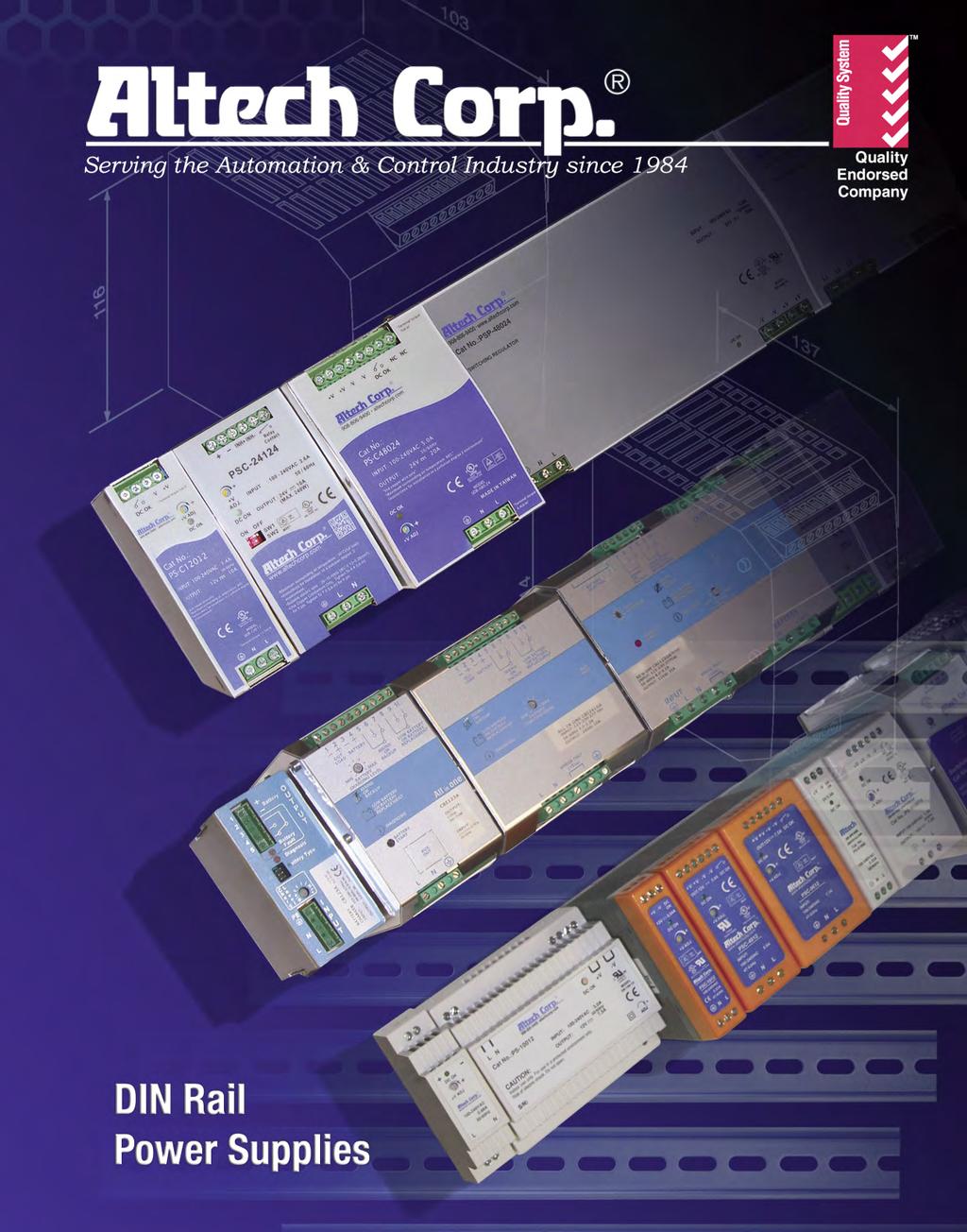
DIN Rail Power Supplies
|
|
|
- Cornelius Thornton
- 6 years ago
- Views:
Transcription
1


2 DIN Rail Power Supplies Since 1984, Altech Corporation has grown to become a leading supplier of automation and industrial control components. Headquartered in Flemington, NJ, Altech has an experienced staff of engineering, manufacturing and sales personnel to provide the highest quality products with superior service. This is the Altech Commitment! In response to a growing market for high power regulated Power Supplies, Altech introduced the new Din Rail mountable power supply line. They are reliable, cost effective, space economical and easy to install and maintain. They are able to handle any industrial process requirement. In addition, you do not need to oversize them; they are designed to work on % load capacity. The universal input, power factor correction and many approvals proves that Altech Power Supplies will function worldwide on a wide variety of applications. Wide operation temperature range, high efficiency and many protections make Altech Power supplies your best choice. Our well trained technical experts welcome the opportunity to answer your technical questions and provide solutions to your automation and control needs. Give us a call or visit Quality Commitment Altech s control components meet diverse national and international standards such as UL, NEC, CSA, IEC, VDE and more. Altech provides superior customer service and delivery through Total Quality Management and Continuous Process Improvement. Altech is ISO 9001 approved. We perform these services with honesty and integrity and are committed to achieve these goals. Altech Corp. 35 Royal Road Flemington, NJ Phone (908) FAX (908)
3 DIN Rail Power Supplies Selection Guide PSC Compact Class 2 Series Compact Design and Lightweight Class 2, UL 1310 Recognized Brown-out protection 10W to 480W rated power Universal single phase input PSA Flex Series (1 Phase) Flex power, solid metal housing UL 508 listed 120W to 600W rated power High efficiency with Boost Power Single phase input PSB Flex Series (2 & 3 Phase) Flex power, solid metal housing UL 508 listed 120W to 600W rated power High efficiency with Boost Power Two and Three phase input PS-S Slim line Series Slim Line Design, plastic housing UL 508 listed DC OK contact 10W to W rated power Universal single phase input PS Low Profile Series Low profile Design, plastic housing UL Recognized Isolation Class II 10W to W rated power Universal single phase input PS Industrial Series Robust Metal housing UL 508 listed Built in active PFC function 75W to 960W rated power Single and three phase universal input PS-C and W Series Narrow design, small metal housing UL 508 listed 150% pick load capacity 120W to 480W rated power Single and two phase wide input CBI DC UPS System Fully automated battery care module Three charging modes 12, 24, 36 and 48V DC single outputs / VAC input System start from battery function CB Battery Chargers Intelligent battery chargers Suitable for most common battery types Adjustable charging current 2 VDC and 24VDC single output VAC input Accessories Redundancy diode module UPS controller module Battery holders and enclosures Ultra capacitor modules FAQ Index Terms & Conditions Altech Corp. 35 Royal Road Flemington, NJ Phone (908) FAX (908)
4 PS Low Profile PS-S Slimine PSA & PSB Flex PSC Class 2 Compact SINGLE PHASE SINGLE PHASE TWO (THREE) PHASE SINGLE PHASE Cat. No. Rated Current VDC PSC-10xx 0.84A 0.67A 0.42A PSC-20xx PSC-40xx PSC-60xx PSC-96xx PSC-151xx PSC-241xx PSC-481xx PSC-RM20 PSA-120xx PSA-180xx PSA-360xx PSA-600xx PSB-120xx PSB-180xx PSB-360xx PSB-600xx PS-S10xx PS-S20xx PS-S40xx PS-S60xx PS-Sxx PS-15xx PS-30xx PS-45xx PS-60xx PS-xx Selection Guide Choose your product from a wide range of features and options, suitable for almost all applications. 1.7A 1.4A 1A 3.4A 2.7A 1.7A 0.85A 4A 5A 2.5A 1.25A 7.5A 6.4A 4A 2A 6.3A 3.2A 10A 5A 20A 10A 20A 5A 7.5A 14A 25A 5A 7.5A 14A 25A 2A 0.84A 0.67A 0.42A 3A 1.67A 1.34A 1 6A 3.33A 1.7A 0.83A 10A 5A 2.5A 1.25A 7.5A 4A 2A 2.4A 1.25A 1A 0.63A 3A 2A 2A 1.5A 5A 3.5A 2.8A 2A 6.5A 4.5A 4A 2.5A 7.5A 6.5A 4.2A Universal Input Switch Select Input Parallel Option UL 508 Listed UL Rec. UL 1310 Rec. EN NEC Class 2 Compliant DC OK Short Circuit Overload Over Voltage Over Temperature CB 4 For the latest on Altech Power Supply specifications please visit
5 Selection Guide Choose your product from a wide range of features and options, suitable for almost all applications. PS Industrial SINGLE PHASE THREE PHASE Cat. No. PS-75xx PS-120xx PSH-120xx PSP-240xx PSP-480xx PSP-480Sxx PST-240xx PST-480xx PST-960xx VDC PST-960Pxx Output Voltage A 3.2A 1.6A 10A 5A 2.5A 5A 2.5A 10A 5A 20A 10A 20A 10A 10A 5A 20A 10A 40A 20A 40A 20A Universal Input Switch Select Input Parallel Option UL 508 Listed UL Rec. UL 1310 Rec. EN NEC Class 2 Compliant DC OK Short Circuit Overload Over Voltage Over Temperature CB Compact Housing SINGLE PHASE WIDE VOLTAGE PS-C120xx PS-C240xx PSH-C480xx PSP-C480Pxx PSW-120xx PSW-240xx PSW-480Pxx 10A 5A 2.5A 10A 5A 20A 10A 20A 10A 10A 5A 2.5A 10A 5A CBI12xx 3-25A DC-UPS CBI24xx CBI48xx CBI280 xx 3-20A 5-10A 12V/15A 24V/10A 36V/7A 48V/5A MULTI-VOLTAGE MULTI-VOLTAGE Battery Charger CB12xx 3-35A CB24xx 3-20A CB12245A 6 A 5 A Acces. PS-RDN 21-28V PS-UPS 21-28V Three Phase Input Selected items, see data sheet 220V INPUT ONLY Special order item / not UL approved. Wide Range Input DC OK signal Altech Corp. 35 Royal Road Flemington, NJ Phone (908) FAX (908)
6 Compact Single Phase Power Supply (PSC) ALTECH s Compact DIN rail switching power supply, PSC Series designed for the fast growing demand of DIN rail applications. These 10W to 480W models are enclosed with fully isolated plastic or metal case to prevent users from hazardous shock. The design complies with the compact requirements that the precious space on the industrial rail can be preserved effectively. Featuring up to 94% of efficiency, this series is cooled only by free air convection up to 70 C that significantly increase the reliability and lifetime of the power supply. Another important feature of PSC Series is its low power consumption (<0.75W) This unique characteristic can significantly expand the application of PSC series beyond just heavy industrial field, but can also be implied to dotcom or IT applications that require green power to save the energy and to obey the anticipated government laws in the near future! Short circuit protection, overload protection, over voltage protection, and the DC OK signal for monitoring the status of power supply are standard functions for the PSC Series. Typical applications include factory automation, process control, electro-mechanical industry, dotcom and IT. Input voltage range: AC inrush current (max): Cold start: DC adjustment range: Overload protection: Over-voltage protection: Other protection: Setup, rise, time (max): Withstand voltage: Working temperature: Safety standards: EMC standards: Military Standard Vibration On/Off V AC; V DC 20A at 115V AC; 40A at 230V AC ±10% rated output voltage 105% rated output power 115%-150% rated output voltage Brown out protection 500ms, 30ms/230V AC 0ms, 30ms/115V AC, at full load I/P-O/P: 3KV AC, I/P-FG:1.5KV AC, O/P-FG:0.5KV AC -20 to +70 C (-4 to +158 F), refer to output de-rating curve UL508 listed, UL1310 recognized, TUV approved EN compliant EN55022 class B EN60-4-2,3,4,5,6,8,11 ENV50204; EN55024; EN60-6-1; EN ; Light Industry Level criteria A MIL-HDBK-217F withstands 2G test Built in remote ON/OFF function (metal case only) 6 For the latest on Altech Power Supply specifications please visit
 No load power consumption <0.")
7 Compact Single Phase Power Supply (PSC) Features: Universal AC input/full range Protections: Short circuit / Overload / Overvoltage Cooling by free air convection DIN rail mountable UL1310 NEC class 2 / LPS compliant (12V,24V,48V only) No load power consumption <0.75W LED indicator for power on % full load burn-in test DC OK relay contact 3 year warranty Multiple output connector for easy wiring on PS-S40, PS-S60 and PS-S models 35mm DIN Rail Mounting Robust plastic housing DC on LED signal Adjustable DC output voltage Easy to understand layout panel CE Compliance UL508 Listed UL1310 Recognized Universal Input Compact for maximized panel space Multiple output connector for easy wiring 35mm DIN Rail Mounting Adjustable DC output voltage DC on LED signal Easy to understand layout panel CE Compliance Metal housing Universal Input Compact for maximized panel space Altech Corp. 35 Royal Road Flemington, NJ Phone (908) FAX (908)
8 Compact Single Phase Power Supply (PSC) E E W Single Output Industrial DIN Rail Power Supply Cat. No. Output Tol. Ripple & Efficiency NOTES V DC A % Noise PSC V DC 0.84A ±1% mvp-p 81% PSC V DC 0.67A ±1% mvp-p 81% PSC V DC 0.42A ±1% 120 mvp-p 81% 20W Single Output Industrial DIN Rail Power Supply Cat. No. Output Tol. Ripple & Efficiency NOTES V DC A % Noise PSC V DC 1.7A ±1% mvp-p 83% PSC V DC 1.4A ±1% mvp-p 85% PSC V DC 1A ±1% 120 mvp-p 86% 40W Single Output Industrial DIN Rail Power Supply Cat. No. Output Tol. Ripple & Efficiency NOTES V DC A % Noise PSC V DC 3.4A ±1% mvp-p 84% PSC V DC 2.7A ±1% mvp-p 84% PSC V DC 1.7A ±1% 120 mvp-p 84% PSC V DC 0.85A ±1% 180 mvp-p 85% 60W Single Output Industrial DIN Rail Power Supply Cat. No. Output Tol. Ripple & Efficiency NOTES V DC A % Noise PSC V DC 5A ±1% mvp-p 86% PSC V DC 4A ±1% mvp-p 87% PSC V DC 2.5A ±1% 120 mvp-p 87% PSC V DC 1.25A ±1% 180 mvp-p 88% 96W Single Output Industrial DIN Rail Power Supply Cat. No. Output Tol. Ripple & Efficiency NOTES V DC A % Noise PSC-9612* 12V DC 7.5A ±1% 180 mvp-p 87% PSC-9615* 15V DC 6.4A ±1% 180 mvp-p 87% PSC V DC 4A ±1% 180 mvp-p 88% PSC V DC 2A ±1% 250 mvp-p 87% *Not included in UL file E For the latest on Altech Power Supply specifications please visit
9 SPECIFICATIONS PSC-10 Terminal Pin. No Assign. (TB1) Terminal Pin. No Assign. (TB2) Series Pin No. Assignment Pin No. Assignment 1 FG 4 DC OUTPUT +V 2 AC/N 5 DC OUTPUT -V 3 AC/L 6 DC OK SIGNAL Universal Input: V AC, V DC full range; 110V AC; 230V AC Connection: Input - 2 poles, Output 2 poles, single screw terminal Size (WxHxD): 23x90x99mm (0.9x3.54x3.94 inches) Packaging: 1/box; 0.29lbs / 0.13Kg PSC-20 Series 90 Terminal Pin. No Assign. (TB1) Terminal Pin. No Assign. (TB2) Pin No. Assignment Pin No. Assignment 1 FG 4 DC OUTPUT +V 2 AC/N 5 DC OUTPUT -V 3 AC/L 6 DC OK SIGNAL Universal Input: V AC, V DC full range; 110V AC; 230V AC Connection: Input - 2 poles, Output 2 poles, single screw terminal Size (WxHxD): 23x90x99mm (0.9x3.54x3.94 inches) Packaging: 1/box; 0.32lbs / 0.14Kg PSC-40 Series 90 Terminal Pin. No Assign. (TB1) Terminal Pin. No Assign. (TB2) Pin No. Assignment Pin No. Assignment 1 FG 1/2 DC OUTPUT +V 2 AC/N 3/4 DC OUTPUT -V 3 AC/L 5/6 DC OK Relay Contact Universal Input: V AC, V DC full range; 115V AC, 230V AC Connection: Input - 2 poles, Output 2 poles, double screw terminal Size (WxHxD): 40x90x99mm (1.57x3.54x3.94 inches) Packaging: 1/box; 0.63lbs / 0.28Kg PSC-60 Series 90 Terminal Pin. No Assign. (TB1) Terminal Pin. No Assign. (TB2) Pin No. Assignment Pin No. Assignment 1 FG 1/2 DC OUTPUT +V 2 AC/N 3/4 DC OUTPUT -V 3 AC/L 5/6 DC OK Relay Contact Universal Input: V AC, V DC full range; 115V AC, 230V AC Connection: Input - 2 poles, Output 2 poles, double screw terminal Size (WxHxD): 40x90x99mm (1.57x3.54x3.94 inches) Packaging: 1/box; 0.67lbs / 0.3Kg PSC-96 Series Terminal Pin. No Assign. (TB1) Terminal Pin. No Assign. (TB2) Pin No. Assignment Pin No. Assignment 1 FG 1/2 DC OUTPUT +V 2 AC/N 3/4 DC OUTPUT -V 3 AC/L 5/6 DC OK Relay Contact Universal Input: V AC, V DC full range; 115V AC, 230V AC Connection: Input - 2 poles, Output 2 poles, double screw terminal Size (WxHxD): 55x90x99mm (2.17x3.54x3.94 inches) Packaging: 1/box; 0.9lbs / 0.4Kg Altech Corp. 35 Royal Road Flemington, NJ Phone (908) FAX (908)
10 PSC-10 Series E E Features: Universal AC input (88-264V AC) Protections: Short Circuit / Overload / Overvoltage Brown-out protection Installed on DIN rail TS35 / 7.5 or 15 True DC OK signal output All wiring 105 C long life electrolytic capacitors High operation temperature up to 70 C Withstands 2G vibration test High efficiency, long life and high reliability 3 year warranty UL1310 Class 2 Power unit / LPS pass UL508 (Industrial control equipment) listed OUTPUT INPUT PROTECTION ENVIRONMENT SAFETY & EMC OUTPUT Cat. No. PSC-1012 PSC-1015 PSC-1024 DC VOLTAGE 12V 15V 24V RATED CURRENT 0.84A 0.67A 0.42A CURRENT RANGE 0~0.84A 0~0.67A 0~0.42A RATED POWER 10.08W 10.05W 10.08W RIPPLE & NOISE (max) mvp-p mvp-p 120mVp-p Ripple & noise are measured at 20MHz of bandwidth by using a 12 twisted pair-wire terminated with a 0.1µF & 47µF parallel capacitor VOLTAGE ADJ. RANGE 10.8~13.2V 13.5~16.5V 21.6~26.4V VOLTAGE TOLERANCE ±1.0% ±1.0% ±1.0% Tolerance: includes set up tolerance, line regulation and load regulation. LINE REGULATION ±1.0% ±1.0% ±1.0% LOAD REGULATION ±1.0% ±1.0% ±1.0% SETUP, RISE TIME < 800ms, < ms/230v AC at full load HOLD UP TIME (Typ.) > 32ms / 230V AC; > 16ms / 115V AC at full load VOLTAGE RANGE 88V~264VAC; 124V~370VDC Derating may be needed under low input voltages. Please check the derating curve for more details. FREQUENCY RANGE 47~63Hz EFFICIENCY (Typ.) 81% 81% 81% AC CURRENT (Typ.) 0.23A/115VAC; 0.17A/230VAC INRUSH CURRENT (Typ.) 15A / 115V AC; 30A / 230V AC LEAKAGE CURRENT < 1mA/ 230VAC OVERLOAD PROTECTION > 102% rated output power Protection type: Constant current limiting, recovers automatically after fault condition is removed. OVERVOLTAGE PROTECTION 115%~150% rated output voltage Protection type: Latch-off mode. OVER TEMPERATURE PROTECTION Power supply shut down at 70 C constant current limiting / output voltage goes to 0; re-power on to recover WORKING TEMP. -20 ~ +70 C (Refer to output load derating curve) WORKING HUMIDITY 20 ~ 90% RH non-condensing STORAGE TEMP. / HUMIDITY -40 ~ +85 C; 10 ~ 95% RH TEMP. COEFFICIENT ±0.03% / C (0 ~ 50 C) VIBRATION 10 ~ 500Hz, 2G 10min. / 1cycle, 60 min. each long X,Y, Z axes SAFETY STANDARDS UL508, TUV EN :2006+A11, UL1310 NEC class 2 compliant WITHSTAND VOLTAGE I/P-O/P: 3KVAC (4242DC) I/P-FG: 1.5KVAC (2121DC) 1 minute ISOLATION RESISTANCE I/P-O/P, I/P-FG, O/P-FG: M Ohms/500VDC EMI CONDUCTION & RADIATION EN55022:2006+A1:2007 Class B HARMONIC CURRENT EN60-3-2:2006 Class A, EN60-3-3:2008 EMS IMMUNITY EN :2000, EN55024:1998+A1:2001+A2:2003 light industry level, criteria A The power supply is considered a component which will installed into a final equipment. The final equipment must be re-confirmed that it still meets EMC directives. DC OK Signal Open collector. Max: 40mA MTBF 562.7K hrs MIL-HDBK-217K DIMENSION 23x90x99 mm (WxHxD) PACKING 0.13Kg/48 pcs. / 7.44Kg CONNECTION I/P 3 poles, O/P: 3 poles screw DIN terminal COOLING Free air convection All parameters NOT specially mentioned are measured at 230V AC input, rated load and 25 C of ambient temperature. 10 For the latest on Altech Power Supply specifications please visit
11 PSC-10 Series Mechanical Specification Unit : mm / inch Terminal Pin. No Assign. (TB1) Pin No. Assignment 1 FG 2 AC/N 3 AC/L 90 Terminal Pin. No Assign. (TB2) Pin No. Assignment 4 DC OUTPUT +V 5 DC OUTPUT -V 6 DC OK SIGNAL 5 5 Application of DC OK Active Signal (a)5v signal (b)led (c)relay DC OK R 5.1V Model 12V 15V R DC OK R Model 12V 15V R DC OK Relay RL Model 12V 15V R V- 24V V- 24V V- 24V Block Diagram DC OK DC OK I/P EMI FILTER RECTIFIERS & FILTER POWER SWITCHING RECTIFIERS & FILTER +V -V O.C.P DETECTION CIRCUIT O.L.P. CONTROL O.V.P. Derating Curve Load V.S Temp. Load V.S I/P Voltage Ta=25 C 90 Load (%) Load (%) VAC Ambient Temperature ( C) Input Voltage(VAC) 60Hz Note: All dimensions are in millimeters, to convert to inches multiply by Altech Corp. 35 Royal Road Flemington, NJ Phone (908) FAX (908)
12 PSC-20 Series E E Features: Universal AC input (88-264V AC) Protections: Short Circuit / Overload / Overvoltage Brown-out protection Installed on DIN rail TS35 / 7.5 or 15 True DC OK signal output All wiring 105 C long life electrolytic capacitors High operation temperature up to 70 C Withstands 2G vibration test High efficiency, long life and high reliability 3 year warranty UL1310 Class 2 Power unit / LPS pass UL508 (Industrial control equipment) listed OUTPUT INPUT PROTECTION ENVIRONMENT SAFETY & EMC OUTPUT Cat. No. PSC-2012 PSC-2015 PSC-2024 DC VOLTAGE 12V 15V 24V RATED CURRENT 1.7A 1.4A 1A CURRENT RANGE 0~1.7A 0~1.4A 0~1A RATED POWER 20.4W 21W 24W RIPPLE & NOISE (max) mvp-p mvp-p 120mVp-p Ripple & noise are measured at 20MHz of bandwidth by using a 12 twisted pair-wire terminated with a 0.1µF & 47µF parallel capacitor VOLTAGE ADJ. RANGE 10.8~13.2V 13.5~16.5V 21.6~26.4V VOLTAGE TOLERANCE ±1.0% ±1.0% ±1.0% Tolerance: includes set up tolerance, line regulation and load regulation. LINE REGULATION ±1.0% ±1.0% ±1.0% LOAD REGULATION ±1.0% ±1.0% ±1.0% SETUP, RISE TIME < 800ms, < ms/230v AC at full load HOLD UP TIME (Typ.) > 32ms / 230V AC; > 16ms / 115V AC at full load VOLTAGE RANGE 88V~264VAC; 124V~370VDC Derating may be needed under low input voltages. Please check the derating curve for more details. FREQUENCY RANGE 47~63Hz EFFICIENCY (Typ.) 83% 85% 86% AC CURRENT (Typ.) 0.45A/115VAC; 0.32A/230VAC INRUSH CURRENT (Typ.) 20A / 115V AC; 40A / 230V AC LEAKAGE CURRENT < 1mA/ 230VAC OVERLOAD PROTECTION > 105% rated output power Protection type: Constant current limiting, recovers automatically after fault condition is removed. OVERVOLTAGE PROTECTION 115%~150% rated output voltage Protection type: Latch-off mode. OVER TEMPERATURE PROTECTION Power supply shut down at 70 C constant current limiting / output voltage goes to 0; re-power on to recover WORKING TEMP. -20 ~ +70 C (Refer to output load derating curve) WORKING HUMIDITY 20 ~ 90% RH non-condensing STORAGE TEMP. / HUMIDITY -40 ~ +85 C; 10 ~ 95% RH TEMP. COEFFICIENT ±0.03% / C (0 ~ 50 C) VIBRATION 10 ~ 500Hz, 2G 10min. / 1cycle, 60 min. each long X,Y, Z axes SAFETY STANDARDS UL508, TUV EN :2006+A11, UL1310 NEC class 2 compliant WITHSTAND VOLTAGE I/P-O/P: 4242DC I/P-FG: 2121DC 1 minute ISOLATION RESISTANCE I/P-O/P, I/P-FG, O/P-FG: M Ohms/500VDC EMI CONDUCTION & RADIATION EN55022:2006+A1:2007 Class B HARMONIC CURRENT EN60-3-2:2006 Class A, EN60-3-3:2008 EMS IMMUNITY EN :2000, EN55024:1998+A1:2001+A2:2003 light industry level, criteria A The power supply is considered a component which will installed into a final equipment. The final equipment must be re-confirmed that it still meets EMC directives. DC OK Signal Open collector. Max: 40mA MTBF 120.4K HRS MIL-HDBK-217 (25 C) 131.3K HRS MIL-HDBK-217 (25 C) 125.9K HRS MIL-HDBK-217 (25 C) DIMENSION 23x90x99 mm (WxHxD) PACKING 0.14Kg/48 pcs./7.92kg CONNECTION I/P 3 poles, O/P: 3 poles screw DIN terminal COOLING Free air convection All parameters NOT specially mentioned are measured at 230V AC input, rated load and 25 C of ambient temperature. 12 For the latest on Altech Power Supply specifications please visit
13 PSC-20 Series Mechanical Specification Unit : mm / inch Terminal Pin. No Assign. (TB1) Pin No. Assignment 1 FG 2 AC/N 3 AC/L 90 Terminal Pin. No Assign. (TB2) Pin No. Assignment 4 DC OUTPUT +V 5 DC OUTPUT -V 6 DC OK SIGNAL 5 5 Application of DC OK Active Signal (a)5v signal (b)led (c)relay DC OK R 5.1V Model R 12V 1.5K 15V 2K DC OK R Model R 12V 2.4K 15V 3K DC OK Relay RL Model R 12V V 700 V- 24V 3.9K V- 24V 4.7K V- 24V 1.2K Block Diagram DC OK DC OK I/P EMI FILTER RECTIFIERS & FILTER POWER SWITCHING RECTIFIERS & FILTER +V -V O.C.P DETECTION CIRCUIT O.L.P. CONTROL O.V.P. Derating Curve Load V.S Temp. Load V.S I/P Voltage Ta=25 C 90 Load (%) Load (%) VAC Ambient Temperature ( C) Input Voltage(VAC)60Hz Note: All dimensions are in millimeters, to convert to inches multiply by Altech Corp. 35 Royal Road Flemington, NJ Phone (908) FAX (908)
14 PSC-40 Series E E Features: Universal AC input (88-264V AC) Protections: Short Circuit / Overload / Overvoltage Brown-out protection Installed on DIN rail TS35 / 7.5 or 15 True DC OK signal output All wiring 105 C long life electrolytic capacitors High operation temperature up to 70 C Withstands 2G vibration test High efficiency, long life and high reliability 3 year warranty UL1310 Class 2 Power unit / LPS pass UL508 (Industrial control equipment) listed OUTPUT INPUT PROTECTION ENVIRONMENT SAFETY & EMC OUTPUT Cat. No. PSC-4012 PSC-4015 PSC-4024 PSC-4048 DC VOLTAGE 12V 15V 24V 48V RATED CURRENT 3.4A 2.7A 1.7A 0.85A CURRENT RANGE 0 ~ 3.4A 0 ~ 2.7A 0 ~ 1.7A 0 ~ 0.85A RATED POWER 40.8W 40.5W 40.8W 40.8W RIPPLE & NOISE (max) mvp-p mvp-p 120mVp-p 180mVp-p Ripple & noise are measured at 20MHz of bandwidth by using a 12 twisted pair-wire terminated with a 0.1µF & 47µF parallel capacitor VOLTAGE ADJ. RANGE 10.8 ~ 13.2V 13.5 ~ 16.5V 21.6 ~ 26.4V 43.2 ~ 52.8V VOLTAGE TOLERANCE ±1.0% ±1.0% ±1.0% ±1.0% Tolerance: includes set up tolerance, line regulation and load regulation. LINE REGULATION ±1.0% ±1.0% ±1.0% ±1.0% LOAD REGULATION ±1.0% ±1.0% ±1.0% ±1.0% SETUP, RISE TIME < 800ms, < 50ms / 230VAC at full load HOLD UP TIME (Typ.) > 32ms / 230VAC; >16ms / 115VAC at full load VOLTAGE RANGE 88 ~ 264VAC; 124 ~ 370VDC Derating may be needed under low input voltages. Please check the derating curve for more details. FREQUENCY RANGE EFFICIENCY (Typ.) 47~63Hz 84% 84% 84% 85% AC CURRENT (Typ.) 0.8 A / 115VAC; 0.4A / 230VAC INRUSH CURRENT (Typ.) COLD START 30A / 115VAC; 60A / 230VAC LEAKAGE CURRENT < 1mA/ 230VAC OVERLOAD PROTECTION > 105% rated output power Protection type: Constant current limiting, recovers automatically after fault condition is removed. OVERVOLTAGE PROTECTION 115% ~ 150% rated output voltage Protection type: latch-off mode OVER TEMPERATURE PROTECTION Power supply shut down at 70 C constant current limiting / output voltage goes to 0; re-power on to recover WORKING TEMP. -20 ~ +70 C (Refer to output load derating curve) WORKING HUMIDITY 20 ~ 90% RH non-condensing STORAGE TEMP. / HUMIDITY -40 ~ +85 C; 10 ~ 95% RH TEMP. COEFFICIENT ±0.03% / C (0 ~ 50 C) VIBRATION 10 ~ 500Hz, 2G 10min. / 1cycle, 60 min. each long X,Y, Z axes SAFETY STANDARDS UL508, TUV EN :2006+A11, UL1310 NEC class 2 compliant WITHSTAND VOLTAGE I/P-O/P: 4242DC I/P-FG: 2121DC 1 minute ISOLATION RESISTANCE I/P-O/P, I/P-FG, O/P-FG: M Ohms/500VDC EMI CONDUCTION & RADIATION EN55022: 2006 Class B HARMONIC CURRENT EN60-3-2: 2006 Class A, EN60-3-3: 1995+A1: 2001+A2: 2005 EMS IMMUNITY EN :2000, EN55024:1998+A1:2001+A2:2003 light industry level, criteria A The power supply is considered a component which will installed into a final equipment. The final equipment must be re-confirmed that it still meets EMC directives. DC OK Signal Relay contact (30VDC / 1A, 120VAC / 1A) MTBF 947.2K hrs MIL-HDBK-217K DIMENSION 40x90x99 mm (WxHxD) PACKING 0.28Kg/27 pcs./8.76kg CONNECTION I/P 3 poles, O/P: 6 poles screw DIN terminal COOLING Free air convection All parameters NOT specially mentioned are measured at 230V AC input, rated load and 25 C of ambient temperature. 14 For the latest on Altech Power Supply specifications please visit
15 PSC-40 Series Mechanical Specification Unit : mm / inch Terminal Pin. No Assign. (TB1) Pin No. Assignment 1 FG 2 3 AC/N AC/L Terminal Pin. No Assign. (TB2) 90 Pin No. Assignment 1,2 DC OUTPUT +V 3,4 DC OUTPUT -V 5,6 DC OK RELAY CONTACT N L Block Diagram DC OK I/P EMI FILTER RECTIFIERS & FILTER POWER SWITCHING RECTIFIERS & FILTER +V -V O.C.P. DC OK DETECTION CIRCUIT O.L.P. CONTROL O.V.P. DC OK Relay Contact Contact Close Contact Open Contact Ratings (max.) When the output voltage reaches the adjusted output voltage When the output voltage drop below 90% rated output voltage 30V / 1A resistive load Derating Curve Load V.S Temp. Load V.S I/P Voltage Ta=25 C 90 Load (%) Load (%) VAC Ambient Temperature ( C) Input Voltage(VAC)60Hz Note: All dimensions are in millimeters, to convert to inches multiply by Altech Corp. 35 Royal Road Flemington, NJ Phone (908) FAX (908)
16 PSC-60 Series E E Features: Universal AC input (88-264V AC) Protections: Short Circuit / Overload / Overvoltage Brown-out protection Installed on DIN rail TS35 / 7.5 or 15 True DC OK signal output All wiring 105 C long life electrolytic capacitors High operation temperature up to 70 C Withstands 2G vibration test High efficiency, long life and high reliability 3 year warranty UL1310 Class 2 Power unit / LPS pass UL508 (Industrial control equipment) listed OUTPUT INPUT PROTECTION ENVIRONMENT SAFETY & EMC OUTPUT Cat. No. PSC-6012 PSC-6015 PSC-6024 PSC-6048 DC VOLTAGE 12V 15V 24V 48V RATED CURRENT 5A 4A 2.5A 1.25A CURRENT RANGE 0 ~ 5A 0 ~ 4A 0 ~ 2.5A 0 ~ 1.25A RATED POWER 60W 60W 60W 60W RIPPLE & NOISE (max) mvp-p mvp-p 120mVp-p 180mVp-p Ripple & noise are measured at 20MHz of bandwidth by using a 12 twisted pair-wire terminated with a 0.1µF & 47µF parallel capacitor VOLTAGE ADJ. RANGE 10.8 ~ 13.2V 13.5 ~ 16.5V 21.6 ~ 26.4V 43.2 ~ 52.8V VOLTAGE TOLERANCE ±1.0% ±1.0% ±1.0% ±1.0% Tolerance: includes set up tolerance, line regulation and load regulation. LINE REGULATION ±1.0% ±1.0% ±1.0% ±1.0% LOAD REGULATION ±1.0% ±1.0% ±1.0% ±1.0% SETUP, RISE TIME < 800ms, < 50ms / 230VAC at full load Length of set up time is measured at sold first start. Turning ON/OFF the power supply may lead to increase of the set up time. HOLD UP TIME (Typ.) > 32ms / 230VAC; >16ms / 115VAC at full load VOLTAGE RANGE 88 ~ 264VAC; 124 ~ 370VDC Derating may apply in low input voltage. Please check the derating curve for more details. FREQUENCY RANGE 47~63Hz EFFICIENCY (Typ.) 86% 87% 87% 88% AC CURRENT (Typ.) 1.3 A / 115VAC; 0.6A / 230VAC INRUSH CURRENT (Typ.) COLD START 30A / 115VAC; 60A / 230VAC LEAKAGE CURRENT <1mA / 230VAC OVER LOAD PROTECTION > 102% rated output power Protection type: Constant current limiting, recovers automatically after fault condition is removed OVER VOLTAGE PROTECTION 115% ~ 150% rated output voltage Protection type: latch-off mode OVER TEMPERATURE PROTECTION Power supply shut down at 70 C constant current limiting / output voltage goes to 0; re-power on to recover WORKING TEMP. -20 ~ +70 C (Refer to output load derating curve) WORKING HUMIDITY 20 ~ 90% RH non-condensing STORAGE TEMP. / HUMIDITY -40 ~ +85 C; 10 ~ 95% RH TEMP. COEFFICIENT ±0.03% / C (0 ~ 50 C) VIBRATION 10 ~ 500Hz, 2G 10min. / 1cycle, 60 min. each long X,Y, Z axes SAFETY STANDARDS UL508, TUV EN :2006+A11, UL1310 NEC class 2 compliant WITHSTAND VOLTAGE I/P-O/P: 4242DC, I/P-FG: 2121DC 1 minute ISOLATION RESISTANCE I/P-O/P, I/P-FG, O/P-FG: M Ohms/500VDC EMI CONDUCTION & RADIATION EN55022: 2006 Class B HARMONIC CURRENT EN60-3-2: 2006 Class A, EN60-3-3: 1995+A1: 2001+A2: 2005 EMS IMMUNITY EN : 2000, EN55024: 1998+A1:2001+A2: 2003 light industry level, criteria A The power supply is considered a component which will installed into a final equipment. The final equipment must be re-confirmed that it still meets EMC directives. DC OK Signal Relay contact (24VDC / 1A, 120VAC / 1A) MTBF 944.6K HRS MIL-HDBK-217F DIMENSION 40x90x99 mm (WxHxD) PACKING 0.3kg; 27pcs / 9.3kg CONNECTION I/P: 3 poles, O/P: 6 poles screw DIN terminal COOLING Free air convection All parameters NOT specially mentioned are measured at 230V AC input, rated load and 25 C of ambient temperature. 16 For the latest on Altech Power Supply specifications please visit
17 PSC-60 Series Mechanical Specification Unit : mm / inch Terminal Pin. No Assign. (TB1) Pin No. Assignment 1 FG 2 3 AC/N AC/L Terminal Pin. No Assign. (TB2) 90 Pin No. Assignment 1,2 DC OUTPUT +V 3,4 DC OUTPUT -V 5,6 DC OK RELAY CONTACT N L Block Diagram DC OK I/P EMI FILTER RECTIFIERS & FILTER POWER SWITCHING RECTIFIERS & FILTER +V -V O.C.P. DC OK DETECTION CIRCUIT O.L.P. CONTROL O.V.P. DC OK Relay Contact Contact Close Contact Open Contact Ratings (max.) When the output voltage reaches the adjusted output voltage When the output voltage drop below 90% rated output voltage 30V / 1A resistive load Derating Curve Load V.S Temp. Load V.S I/P Voltage Ta=25 C 90 Load (%) Load (%) VAC Ambient Temperature ( C) Input Voltage(VAC)60Hz Note: All dimensions are in millimeters, to convert to inches multiply by Altech Corp. 35 Royal Road Flemington, NJ Phone (908) FAX (908)
18 PSC-96 Series E E Features: Universal AC input (88-264V AC) Protections: Short Circuit / Overload / Overvoltage Brown-out protection Installed on DIN rail TS35 / 7.5 or 15 True DC OK signal output All wiring 105 C long life electrolytic capacitors High operation temperature up to 70 C Withstands 2G vibration test High efficiency, long life and high reliability 3 year warranty UL1310 Class 2 Power unit / LPS pass UL508 (Industrial control equipment) listed OUTPUT INPUT PROTECTION ENVIRONMENT SAFETY & EMC OUTPUT Cat. No. PSC-9612* PSC-9615* PSC-9624 PSC-9648 DC VOLTAGE 12V 15V 24V 48V RATED CURRENT 7.5A 6.4A 4A 2A CURRENT RANGE 0 ~ 7.5A 0 ~ 6.4A 0 ~ 4A 0 ~ 2A RATED POWER 90W 96W 96W 96W RIPPLE & NOISE (max) 180mVp-p 180mVp-p 180mVp-p 250mVp-p Ripple & noise are measured at 20MHz of bandwidth by using a 12 twisted pair-wire terminated with a 0.1µF & 47µF parallel capacitor VOLTAGE ADJ. RANGE 10.8 ~ 13.2V 13.5 ~ 16.5V 21.6 ~ 26.4V 43.2 ~ 52.8V VOLTAGE TOLERANCE ±1.0% ±1.0% ±1.0% ±1.0% Tolerance: includes set up tolerance, line regulation and load regulation. LINE REGULATION ±1.0% ±1.0% ±1.0% ±1.0% LOAD REGULATION ±2.0% ±2.0% ±2.0% ±2.0% SETUP, RISE TIME < 800ms, < 40ms / 230VAC at full load HOLD UP TIME (Typ.) > 32ms / 230VAC; >16ms / 115VAC at full load VOLTAGE RANGE 88 ~ 264VAC; 124 ~ 370VDC Derating may apply in low input voltage. Please check the derating curve for more details. FREQUENCY RANGE 47Hz~63Hz POWER FACTOR (Typ.) < 0.92 / 230VAC; < 0.98 / 115VAC at full load EFFICIENCY (Typ.) 87% 87% 88% 87% AC CURRENT (Typ.) 1.1 A / 115VAC; 0.55A / 230VAC INRUSH CURRENT (Typ.) COLD START 30A / 115VAC; 60A / 230VAC LEAKAGE CURRENT <1mA / 230VAC OVER LOAD PROTECTION > 102% rated output power Protection type: Constant current limiting, recovers automatically after fault condition is removed. OVER VOLTAGE PROTECTION 115% ~ 150% rated output voltage Protection type: latch-off mode OVER TEMPERATURE PROTECTION 90 C ± 10 C (RTH2) detect on heat sink of power transistor Protection type: Shut down overvoltage, re-power on to recover WORKING TEMP. -20 ~ +70 C (Refer to output load derating curve) WORKING HUMIDITY 20 ~ 90% RH non-condensing STORAGE TEMP. / HUMIDITY -40 ~ +85 C; 10 ~ 95% RH TEMP. COEFFICIENT ±0.03% / C (0 ~ 50 C) VIBRATION 10 ~ 500Hz, 2G 10min. / 1cycle, 60 min. each long X,Y, Z axes SAFETY STANDARDS UL508, TUV EN :2006+A11, UL1310 NEC class 2 compliant WITHSTAND VOLTAGE I/P-O/P: 4242DC I/P-FG: 2121DC 1 minute ISOLATION RESISTANCE I/P-O/P, I/P-FG, O/P-FG: M Ohms/500VDC EMI CONDUCTION & RADIATION EN55022:2006 Class B HARMONIC CURRENT EN60-3-2:2006 Class A, EN60-3-3: 1995+A1: 2001+A2: 2005 EMS IMMUNITY EN :2000, EN55024:1998+A1:2001+A2:2003 light industry level, criteria A The power supply is considered a component which will installed into a final equipment. The final equipment must be re-confirmed that it still meets EMC directives. DC OK Signal Relay contact (24VDC / 1A, 120VAC / 1A) MTBF 120.4K Hrs MIL-HDBK-217F DIMENSION 55x90x99 mm (WxHxD) PACKING 0.4Kg/24 pcs. / 10.8Kg CONNECTION l/p 3 poles, 0/P: 6 poles screw DIN terminal COOLING Free air convection All parameters NOT specially mentioned are measured at 230V AC input, rated load and 25 C of ambient temperature. *Not included in UL E For the latest on Altech Power Supply specifications please visit
19 PSC-96 Series Mechanical Specification Unit : mm / inch Terminal Pin. No Assign. (TB1) Pin No. Assignment 1 FG 2 AC/N 3 AC/L Terminal Pin. No Assign. (TB2) 90 Pin No. Assignment 1,2 DC OUTPUT +V 3,4 DC OUTPUT -V 5,6 DC OK RELAY CONTACT Block Diagram DC OK I/P EMI FILTER & RECTIFIERS PFC CIRCUIT POWER SWITCHING RECTIFIERS & FILTER +V -V O.C.P. DC OK O.L.P. O.V.P. O.L.P. DETECTION CIRCUIT PWM&PFC CONTROL O.V.P. DC OK Relay Contact O.T.P. Contact Close Contact Open Contact Ratings (max.) When the output voltage reaches the adjusted output voltage When the output voltage drop below 90% rated output voltage 30V / 1A resistive load Derating Curve Load V.S Temp. Load V.S I/P Voltage Ta=25 C 90 Load (%) Load (%) VAC Ambient Temperature ( C) Input Voltage(VAC) 60Hz Note: All dimensions are in millimeters, to convert to inches multiply by Altech Corp. 35 Royal Road Flemington, NJ Phone (908) FAX (908)
20 Compact Single Phase Power Supply (PSC) E Features: Universal AC input (88-264V AC) Installed on DIN rail TS-35 / 7.5 or 15 Built-in active PFC function, PF > % peak load capability % full load burn-in test Protection: SCP, OLP, OVP, OTP Two selectable peak load modes Built-in DC OK Relay contact Built-in Remote ON / OFF function 3 years warranty UL W DIN Rail Power Supply Cat. No. Phases Output Tol. Ripple & Efficiency NOTES V DC A % Noise PSC V DC 6.3A ±1% 240 mvp-p 87% PSC V DC 3.2A ±1% 480 mvp-p 87% 240W DIN Rail Power Supply Cat. No. Phases Output Tol. Ripple & Efficiency NOTES V DC A % Noise PSC V DC 10A ±1% 150 mvp-p 91% PSC V DC 5A ±1% 300 mvp-p 92% 480W DIN Rail Power Supply Cat. No. Phases Output Tol. Ripple & Efficiency NOTES V DC A % Noise PSC V DC 20A ±1% 240 mvp-p 93% PSC V DC 10A ±1% 480 mvp-p 94% 20A DIN Rail Redundancy Module Cat. No. Phases Output Input NOTES V DC A VDC A PSC-RM V DC 20A 24VDC 2x20A **Other output voltages on request. 20 For the latest on Altech Power Supply specifications please visit
21 SPECIFICATIONS PSC-151 Series Terminal Pin No. Assignment (TB1) Pin NO. Assignment 1 FG 2 AC/L 3 AC/N Terminal Pin No. Assignment (TB2) Pin NO. Assignment 1 DC+ 2 DC- 3 INH+ 4 INH- 5,6 Relay Contact Universal Input: 115VAC / 230VAC Connection Input: 2 poles, single screw terminal Connection Output: 2 poles, single screw terminal Size (WxHxD): 55.5x12.5x mm (2.19x4.92x3.93 in.) Packaging: 1/box; 0.72kg (1.6 lbs) Switch No. Assignment SW NO. SW1 SW2 Assignment PEAK LOAD SETTING REMOTE ON/OFF SETTING PSC-241 Series Terminal Pin No. Assignment (TB1) Pin NO. Assignment 1 FG 2 AC/L 3 AC/N Terminal Pin No. Assignment (TB2) Pin NO. Assignment 1 DC+ 2 DC- 3 INH+ 4 INH- 5,6 Relay Contact Switch No. Assignment SW NO. SW1 SW2 Assignment PEAK LOAD SETTING REMOTE ON/OFF SETTING Universal Input: 115VAC / 230VAC Connection Input: 2 poles, single screw terminal Connection Output: 2 poles, single screw terminal Size (WxHxD): 66x12.5x118 mm (2.6x4.9x4.65 in.) Packaging: 1/box; 0.9kg (2.0 lbs) PSC-481 Series Terminal Pin No. Assignment (TB1) Pin NO. Assignment 1 FG 2 AC/L 3 AC/N Terminal Pin No. Assignment (TB2) Pin NO. Assignment 1-3 DC+ 4-6 DC ,10 INH+ INH- DC OK Signal Switch No. Assignment SW NO. Assignment SW1 PEAK LOAD SETTING SW2 REMOTE ON/OFF SETTING Universal Input: 115VAC / 230VAC Connection Input: 2 poles, single screw terminal Connection Output: 2 poles, single screw terminal Size (WxHxD): 86x12.5x123 mm (3.4x4.9x4.85 in.) Packaging: 1/box; 1.45kg (3.2 lbs) PSC-RM20 Terminal Pin. No Assignment (TB1) Pin No. Assignment 1 2 3,4 5 6 Vout+ Vout- Vin- Vin B+ Vin A+ Terminal Pin. No Assignment (TB2) Pin No. Assignment AlarmB1 AlarmB2 AlarmA1 AlarmA Input: 24VDC Connection Input: 2 poles, single screw terminal Connection Output: 2 poles, single screw terminal Size (WxHxD): 55.5x12.5x mm (2.19x4.92x3.93 in.) Packaging: 1/box; 0.72kg (1.6 lbs) Altech Corp. 35 Royal Road Flemington, NJ Phone (908) FAX (908)
22 PSC-151 Series E Features: Universal AC input (88-264V AC) Installed on DIN rail TS-35 / 7.5 or 15 Built-in active PFC function, PF > % peak load capability % full load burn-in test Protection: SCP, OLP, OVP, OTP Two selectable peak load modes Built-in DC OK Relay contact Built-in Remote ON / OFF function 3 years warranty UL 508 OUTPUT INPUT PROTECTION ENVIRONMENT SAFETY & EMC OUTPUT Cat. No. PSC PSC DC VOLTAGE 24V 48V RATED CURRENT 6.3A 3.2A CURRENT RANGE 0~6.3A 0~3.2A RATED POWER 150W 150W PEAK CURRENT 9.45A 4.8A PEAK POWER 225W (3sec.) 3 seconds or 20% duty cycle max. and the average output power should not exceed the rate power. RIPPLE & NOISE (max) 240mVp-p 480mVp-p Ripple & noise are measured at 20MHz of bandwidth by using a 12 twisted pair-wire terminated with a 0.1µF & 47µF parallel capacitor. VOLTAGE ADJ. RANGE -2% ~ +8% -2% ~ +8% VOLTAGE TOLERANCE ±1.0% ±1.0% Tolerance: includes set up tolerance, line regulation and load regulation. LINE REGULATION ±0.5% ±0.5% LOAD REGULATION ±1.0% ±1.0% SETUP, RISE TIME 700ms, 30ms / 230VAC / 115VAC at full load HOLD UP TIME (Typ.) 16ms / 230VAC; 16ms / 115VAC at full load VOLTAGE RANGE 88 ~ 264VAC; 124 ~ 373VDC Derating may apply in low input voltage. Please check the derating curve for more details. FREQUENCY RANGE 47 ~ 63Hz POWER FACTOR(Typ.) 0.9 / 230VAC; 0.98 / 115VAC at full load EFFICIENCY (Typ.) 87% 87% AC CURRENT (Typ.) 2.0A / 115VAC; 1.0A / 230VAC INRUSH CURRENT (Typ.) 33A / 115VAC; 65A / 230VAC LEAKAGE CURRENT <1mA/ 240VAC OVERLOAD PROTECTION 105% ~ 150% rated output power for 3 sec and then shutdown in O/P with auto-recovery. 150% or greater rated power or short circuit is constant current limiting. If O/P drops to 40% output then it auto-recover 5 times; if fault condition is not removed during auto recovery, the system will shut down and needs to be restarted to recover. OVER VOLTAGE 29 ~ 33V 56 ~ 65V Protection type: Latch-off mode, repower on to recover. OVER TEMPERATURE 95 ±5 C (TSW: detect on heatsink of power diode) Protection type: Shut down o/p voltage, recovers automatically after temperature goes down WORKING TEMP. -10 ~ +70 C (Refer to derating curve) Installation clearance: 40mm from top, 20mm from bottom, 5mm from the left and right side are recommended when loaded permanently with full power. In case the adjacent device is a heat source, 15mm clearance is recommended. WORKING HUMIDITY 20 ~ 95% RH non-condensing STORAGE TEMP. / HUMIDITY -40 ~ +85 C, 10 ~ 95% RH TEMP. COEFFICIENT ±0.03% / C (0 ~ 50 C) VIBRATION 10 ~ 500Hz, 2G 10min. / 1cycle, 60min. each along X, Y, Z axes SAFETY STANDARDS UL 508 / TUV EN WITHSTAND VOLTAGE I/P-O/P: 4242VDC, I/P-FG: 2121VDC, O/P-FG: 707VDC, O/P-DC OK: 707VDC ISOLATION RESISTANCE I/P-O/P, I/P-FG, O/P-FG: >M Ohms / 500VDC / 25 C / 70% RH EMI CONDUCTION & RADIATION EN55022 (CISPR22) Class B HARMONIC CURRENT EN60-3-2, -3 EMS IMMUNITY Compliance to EN60-4-2,3,4,5,6,8,11; ENV50204; EN55024; EN60-6-2; (EN ); EN ; heavy industry level; criteria A, MEET SEMI F47 The power supply is considered a component which will installed into a final equipment. The final equipment must be re-confirmed that it still meets EMC directives. DC OK RELAY. CONTACT RATINGS (max) 60VDC / 0.3A, 30VDC / 1A, 30VAC / 0.5A resistive load MTBF 62.7K HRS (MIL-HDBK-217F) DIMENSION 55.5x125.2x99.8 mm (WxHxD) PACKING 0.72kg; 12pcs / 12.8kg COOLING Free air convection All parameters NOT specially mentioned are measured at 230VAC input, rated load and 25 C of ambient temperature. 22 For the latest on Altech Power Supply specifications please visit
23 PSC-151 Series Mechanical Specification Unit : mm / inch Terminal Pin No. Assignment (TB1) Pin NO. Assignment 1 FG 2 AC/L 3 AC/N Terminal Pin No. Assignment (TB2) Pin NO. Assignment 1 DC+ 2 DC- 3 INH+ 4 INH- 5,6 Relay Contact TB Relay Contact 99.8 Switch No. Assignment SW NO. Assignment SW1 PEAK LOAD SETTING SW2 REMOTE ON/OFF SETTING +V ADJ. + DC ON ON OFF SW1 SW TB1 2 3 Block Diagram I/P EMI FILTER & RECTIFIERS PFC CIRCUIT POWER SWITCHING RECTIFIERS & FILTER +V -V O.C.P. FG O.L.P. O.L.P. O.L.P. AC DETECTION CIRCUIT PWM & PFC CONTROL DETECTION CIRCUIT MICRO CIRCUIT O.V.P. O.T.P. Relay C REMOTE CONTROL INH+ INH- DC OK Relay Contact PEAK LOAD CONTROL Contact Close Contact Open Contact Ratings(max.) When the output voltage reaches the adjusted output voltage. When the output voltage drop below 45% rated output voltage. 30V/1A resistive load Note: All dimensions are in millimeters, to convert to inches multiply by Altech Corp. 35 Royal Road Flemington, NJ Phone (908) FAX (908)
24 PSC-151 Series E Peak Load SW1 ON (Mode1) Default setting I I-peak I-normal T-normal T-peak T-peak presents while the unit is working within 110%~150% Rating output power. See curve " B " for the variation in T-peak between output current and holdup time. If T-peak is more than the time setting in curve "B", the output current will drop to the constant current limit (I-normal) that is 105% rating power, meanwhile, I- normal and T-normal will be presenting. See curve "A" for the timing back to I-Peak of T-normal and this Mode can use for easy 2-stage battery charger. 0 T Peak Load SW2 OFF (Mode2) I I-peak T-peak T-peak presents while the unit is working within 110%~150% Rating output power. See curve " B " for the variation in T-peak between output current and holdup time. If T-peak is more than the time setting in curve "B", the output current will be shut down for 3~4 sec, then auto-recovery. 0 3 ~ 4 sec T T- normal (Sec.) % 20% 30% 40% 50% 60% 70% 80% 90% Load (%) CURVE A T- peak (Sec.) I-normal 110% 115% 120% 125% 130% 135% 140% 145% 150% I-peak Load (%) CURVE B 24 For the latest on Altech Power Supply specifications please visit
25 PSC-151 Series Remote ON/OFF The PSU can be turned ON/OFF by using the "Remote Control" function. SW External Power Source I = 6 ~ 20mA SW2 OFF OFF ON ON INH+(3 PIN)/ INH-(4 PIN) SW ON (>2.5V) SW OFF (<0.8V) SW ON (>2.5V) SW OFF (<0.8V) Output Status ENABLE DISABLE DISABLE ENABLE (Default Setting) TB2 + +V ADJ. DC ON Relay Contact ON OFF SW1 SW2 Derating Curve 150 Load (%) For typ. 3sec Continuous (Vertical) Ambient Temperature ( C) AC=230 / 115VAC Output derating VS input Voltage 90 Load (%) VAC Input Voltage (V) 60Hz Ta=25 C Altech Corp. 35 Royal Road Flemington, NJ Phone (908) FAX (908)
26 PSC-241 Series E Features: Universal AC input (88-264V AC) High efficiency 92% and low power dissipation Installed on DIN rail TS-35 / 7.5 or 15 Built-in active PFC function, PF > % peak load capability % full load burn-in test Protection: SCP, OLP, OVP, OTP Two selectable peak load modes Built-in DC OK Relay contact Built-in Remote ON / OFF function 3 years warranty UL 508 OUTPUT INPUT PROTECTION ENVIRONMENT SAFETY & EMC OUTPUT Cat. No. PSC PSC DC VOLTAGE 24V 48V RATED CURRENT 10A 5A CURRENT RANGE 0~10A 0~5A RATED POWER 240W 240W PEAK CURRENT 15A 7.5A PEAK POWER 360W (3sec.) Two selectable peak load modes 3 seconds or 20% duty cycle Max. The average output power should not exceed the rate power. RIPPLE & NOISE (max) 150mVp-p 300mVp-p Ripple & noise are measured at 20MHz of bandwidth by using a 12 twisted pair-wire terminated with a 0.1µF & 47µF parallel capacitor. VOLTAGE ADJ. RANGE -2% ~ +8% -2% ~ +8% VOLTAGE TOLERANCE ±1.0% ±1.0% Tolerance: includes set up tolerance, line regulation and load regulation. LINE REGULATION ±0.5% ±0.5% LOAD REGULATION ±1.0% ±1.0% SETUP, RISE TIME 700ms, 30ms / 230VAC / 115VAC at full load HOLD UP TIME (Typ.) 20ms / 230VAC; 20ms / 115VAC at full load VOLTAGE RANGE 88 ~ 264VAC; 124 ~ 373VDC Derating may apply in low input voltage. Please check the derating curve for more details. FREQUENCY RANGE 47 ~ 63Hz POWER FACTOR (Typ.) 0.96 / 230VAC; 0.96 / 115VAC at full load EFFICIENCY (Typ.) 91% 92% AC CURRENT (Typ.) 2.6A / 115VAC; 1.3A / 230VAC INRUSH CURRENT (Typ.) 33A / 115VAC; 65A / 230VAC LEAKAGE CURRENT <1mA/ 240VAC OVERLOAD 105% ~ 150% rated output power for 3 sec and then shutdown in O/P with auto-recovery. 150% or greater rated power or short circuit is constant current limiting. If O/P drops to 40% output then it auto-recover 5 times; if fault condition is not removed during auto recovery, the system will shut down and needs to be restarted to recover. OVER VOLTAGE 28 ~ 33V 56 ~ 65V Protection type: Shut down O/P voltage with auto-recovery OVER TEMPERATURE 95 ±5 C (TSW: detect on heatsink of power diode) Protection type: Shut down o/p voltage, recovers automatically after temperature goes down WORKING TEMP. -25 ~ +70 C (Refer to output load derating curve) Installation clearances: 40mm on top, 20mm on the bottom, 5mm on the left and right side are recommended when loaded permanently with full power. In case the adjacent device is a heat source, 15mm clearance is recommended. WORKING HUMIDITY 20 ~ 95% RH non-condensing STORAGE TEMP. / HUMIDITY -40 ~ +85 C; 10 ~ 95% RH TEMP. COEFFICIENT ±0.03% C (0 ~ 50 C) VIBRATION 10 ~ 500Hz, 2G 10min. / 1cycle, 60 min. each long X,Y, Z axes SAFETY STANDARDS UL508, TUV EN WITHSTAND VOLTAGE I/P-O/P: 4242VDC I/P-FG2121VDC O/P-F/G: 707VDC O/P-DC OK: 707VDC ISOLATION RESISTANCE I/P-O/P, I/P-FG, O/P-FG: > M Ohms / 500VDC / 25 C / 70% RH EMI CONDUCTION & RADIATION EN55022:2006 Class B HARMONIC CURRENT EN60-3-2: 2006 Class A, ENG0-3-3: A1: 2001+A2: 2005 EMS IMMUNITY EN : 2000, EN55024: 1998+A1: 2001+A2: 2003 light industry level, criteria A The power supply is considered a component which will installed into a final equipment. The final equipment must be re-confirmed that it still meets EMC directives. DC OK RELAY CONTACT RATINGS (max) 60VDC / 0.3A, 30VDC / 1A, 30VAC / 0.5A resistive load MTBF 57K HRS (MIL-HDBK-217F) DIMENSION 65.8x125.2x117.7 mm (WxHxD) PACKING 0.9kg; 12pcs / 12.8kg COOLING Free air convection All parameters NOT specially mentioned are measured at 230VAC input, rated load and 25 C of ambient temperature. 26 For the latest on Altech Power Supply specifications please visit
27 PSC-241 Series Mechanical Specification Unit : mm / inch Terminal Pin No. Assignment (TB1) Pin NO. Assignment 1 FG 2 AC/L 3 AC/N Terminal Pin No. Assignment (TB2) Pin NO. Assignment 1 DC+ 2 DC- 3 INH+ 4 INH- 5,6 Relay Contact TB Relay Contact Switch No. Assignment SW NO. Assignment SW1 PEAK LOAD SETTING SW2 REMOTE ON/OFF SETTING +V ADJ. + DC ON ON OFF SW1 SW TB1 Block Diagram I/P EMI FILTER & RECTIFIERS ACTIVE INRUSH CURRENT LIMITING PFC CIRCUIT POWER SWITCHING RECTIFIERS & FILTER +V -V O.C.P. FG O.L.P. O.L.P. AC DETECTION CIRCUIT PFC CONTROL PWM POWER CONTROL DETECTION CIRCUIT MICRO CIRCUIT O.V.P. O.T.P. Relay Contact REMOTE CONTROL INH+ INH- PEAK LOAD CONTROL DC OK Relay Contact Contact Close When the output voltage reaches the adjusted output voltage. Contact Open When the output voltage drop below 45% rated output voltage. Contact Ratings(max.) 30V/1A resistive load Note: All dimensions are in millimeters, to convert to inches multiply by Altech Corp. 35 Royal Road Flemington, NJ Phone (908) FAX (908)
28 PSC-241 Series E Peak Load SW1 ON (Mode1) Default setting I I-peak I-normal T-normal T-peak T-peak presents while the unit is working within 110%~150% Rating output power. See curve " B " for the variation in T-peak between output current and holdup time. If T-peak is more than the time setting in curve "B", the output current will drop to the constant current limit (I-normal) that is 105% rating power, meanwhile, I- normal and T-normal will be presenting. See curve "A" for the timing back to I-Peak of T-normal and this Mode can use for easy 2-stage battery charger. 0 T Peak Load SW2 OFF (Mode2) I I-peak T-peak T-peak presents while the unit is working within 110%~150% Rating output power. See curve " B " for the variation in T-peak between output current and holdup time. If T-peak is more than the time setting in curve "B", the output current will be shut down for 3~4 sec, then auto-recovery. 0 3 ~ 4 sec T T- normal (Sec.) % 20% 30% 40% 50% 60% 70% 80% 90% Load (%) CURVE A T- peak (Sec.) I-normal 110% 115% 120% 125% 130% 135% 140% 145% 150% I-peak Load (%) CURVE B 28 For the latest on Altech Power Supply specifications please visit
29 PSC-241 Series Remote ON/OFF The PSU can be turned ON/OFF by using the "Remote Control" function. SW TB2 External Power Source I = 6 ~ 20mA SW2 OFF OFF ON ON INH+(3 PIN)/ INH-(4 PIN) SW ON (>2.5V) SW OFF (<0.8V) SW ON (>2.5V) SW OFF (<0.8V) Output Status ENABLE DISABLE DISABLE ENABLE (Default Setting) + +V ADJ. DC ON DC OK ON OFF SW1 SW2 Derating Curve 150 Load (%) For typ. 3sec Continuous (Vertical) Ambient Temperature ( C) AC=230 / 115VAC Output derating VS input Voltage 90 Load (%) VAC Input Voltage(V)60Hz Ta=25 C Altech Corp. 35 Royal Road Flemington, NJ Phone (908) FAX (908)
30 PSC-481 Series E Features: Universal AC input (88-264V AC) Installed on DIN rail TS-35 / 7.5 or 15 Built-in active PFC function, PF > % peak load capability Protection: SCP, OLP, OVP, OTP Two selectable peak load modes Built-in DC OK (Open Collector Signal) Built-in Remote ON / OFF function 3 years warranty UL 508 OUTPUT INPUT PROTECTION ENVIRONMENT SAFETY & EMC OUTPUT Cat. No. PSC PSC DC VOLTAGE 24V 48V RATED CURRENT 20A 10A CURRENT RANGE 0~20A 0~10A RATED POWER 480W 480W PEAK CURRENT 30A 15A PEAK POWER 720W (3sec.) Two selectable peak load modes 3 seconds or 20% duty cycle Max. The average output power should not exceed the rate power. RIPPLE & NOISE (max) 240mVp-p 480mVp-p Ripple & noise are measured at 20MHz of bandwidth by using a 12 twisted pair-wire terminated with a 0.1µF & 47µF parallel capacitor. VOLTAGE ADJ. RANGE -5% ~ +5% VOLTAGE TOLERANCE ±1.0% ±1.0% Tolerance: includes set up tolerance, line regulation and load regulation. LINE REGULATION ±0.5% ±0.5% LOAD REGULATION ±1.0% ±1.0% SETUP, RISE TIME 800ms, ms / 230VAC / 115VAC at full load HOLD UP TIME (Typ.) 16ms / 230VAC; 16ms / 115VAC at full load VOLTAGE RANGE 88 ~ 264VAC; 124 ~ 373VDC Derating may apply in low input voltage. Please check the derating curve for more details. FREQUENCY RANGE 47 ~ 63Hz POWER FACTOR (Typ.) 0.96 / 230VAC / 115VAC at full load EFFICIENCY (Typ.) 93% 94% AC CURRENT (Typ.) 5.0A / 115VAC; 2.5A / 230VAC INRUSH CURRENT (Typ.) 33A / 115VAC; 65A / 230VAC LEAKAGE CURRENT < 1mA/ 240VAC OVERLOAD 105% ~ 150% rated output power for 3 sec and then shutdown in O/P with auto-recovery. 150% or greater rated power or short circuit is constant current limiting. If O/P drops to 40% output then it auto-recover 5 times; if fault condition is not removed during auto recovery, the system will shut down and needs to be restarted to recover. OVER VOLTAGE 29 ~ 33V 56 ~ 65V Protection type: Latch-off mode. OVER TEMPERATURE 95 ±5 C (TSW: detect on heatsink of power diode) Protection type: Shut down o/p voltage, recovers automatically after temperature goes down WORKING TEMP. -20 ~ +70 C (Refer to output load derating curve) Installation clearance: 40mm from top, 20mm from the left and right side are recommended when loaded permanently with full power. In case the adjacent device is a heat sorce, 15mm clearance is recomended. WORKING HUMIDITY 20 ~ 95% RH non-condensing STORAGE TEMP. / HUMIDITY -40 ~ +85 C; 10 ~ 95% RH TEMP. COEFFICIENT ±0.03% C (0 ~ 50 C) VIBRATION 10 ~ 500Hz, 2G 10min. / 1cycle, 60 min. each long X,Y, Z axes SAFETY STANDARDS UL 508 / EN WITHSTAND VOLTAGE I/P-O/P: 4242VDC, I/P-FG: 2121VDC, O/P-FG: 707VDC, O/P-DC OK: 707VDC ISOLATION RESISTANCE I/P-O/P, I/P-FG, O/P-FG: >M Ohms / 500VDC / 25 C / 70% RH EMI CONDUCTION & RADIATION EN (CISPR22), EN HARMONIC CURRENT EN60-3-2, -3-3 EMS IMMUNITY IEC , 3, 4, 5, 6, 8, 11; EN ; EN The power supply is considered a component which will installed into a final equipment. The final equipment must be re-confirmed that it still meets EMC directives. DC OK RELAY CONTACT RATINGS (max) 60VDC / 0.3A, 30VDC / 1A, 30VAC / 0.5A resistive load DIMENSION 86.3x124.8x123.4 mm (WxHxD) PACKING 1.45kg; 8pcs / 12kg All parameters NOT specially mentioned are measured at 230VAC input, rated load and 25 C of ambient temperature. 30 For the latest on Altech Power Supply specifications please visit
31 PSC-481 Series Mechanical Specification Unit : mm / inch Terminal Pin No. Assignment (TB1) Pin NO Assignment FG AC/L AC/N Terminal Pin No. Assignment (TB2) Pin NO. Assignment 1-3 DC+ 4-6 DC ,10 INH+ INH- DC OK Singal TB DC OK Switch No. Assignment SW NO. SW1 SW2 Assignment PEAK LOAD SETTING REMOTE ON/OFF SETTING +V ADJ. + DC ON ON OFF SW1 SW TB Block Diagram I/P EMI FILTER & RECTIFIERS ACTIVE inrush CURRENT LIMITING PFC CIRCUIT POWER SWITCHING RECTIFIERS & FILTER +V -V O.C.P. FG O.L.P. O.L.P. AC DETECTION CIRCUIT PFC CONTROL PWM POWER CONTROL DETECTION CIRCUIT MICRO CIRCUIT O.V.P. O.T.P. DC OK Singal REMOTE CONTROL INH+ INH- PEAK LOAD CONTROL DC OK Relay Contact Contact Ratings(max.) CTR : MIN. 50% at IF = 5mA, VCE = 5V Isolation Voltage Between input and output Viso = 3750Vrms Note: All dimensions are in millimeters, to convert to inches multiply by Altech Corp. 35 Royal Road Flemington, NJ Phone (908) FAX (908)
32 PSC-481 Series E Peak Load SW1 ON (Mode1) Default setting I I-peak I-normal T-normal T-peak T-peak presents while the unit is working within 110%~150% Rating output power. See curve " B " for the variation in T-peak between output current and holdup time. If T-peak is more than the time setting in curve "B", the output current will drop to the constant current limit (I-normal) that is 105% rating power, meanwhile, I- normal and T-normal will be presenting. See curve "A" for the timing back to I-Peak of T-normal and this Mode can use for easy 2-stage battery charger. 0 T Peak Load SW2 OFF (Mode2) I I-peak T-peak T-peak presents while the unit is working within 110%~150% Rating output power. See curve " B " for the variation in T-peak between output current and holdup time. If T-peak is more than the time setting in curve "B", the output current will be shut down for 3~4 sec, then auto-recovery. 0 3 ~ 4 sec T T- normal (Sec.) % 20% 30% 40% 50% 60% 70% 80% 90% Load (%) CURVE A T- peak (Sec.) I-normal 110% 115% 120% 125% 130% 135% 140% 145% 150% I-peak Load (%) CURVE B 32 For the latest on Altech Power Supply specifications please visit
33 PSC-481 Series Remote ON/OFF The PSU can be turned ON/OFF by using the "Remote Control" function. SW TB2 External Power Source I = 6 ~ 20mA SW2 OFF OFF ON ON INH+(3 PIN)/ INH-(4 PIN) SW ON (>2.5V) SW OFF (<0.8V) SW ON (>2.5V) SW OFF (<0.8V) Output Status ENABLE DISABLE DISABLE ENABLE (Default Setting) + +V ADJ. DC ON DC OK ON OFF SW1 SW2 Derating Curve 150 Load (%) For typ. 3sec Continuous (Vertical) Ambient Temperature ( C) AC=230 / 115VAC Output derating VS input Voltage 90 Load (%) VAC Input Voltage(V)60Hz Ta=25 C Altech Corp. 35 Royal Road Flemington, NJ Phone (908) FAX (908)
34 PSC-RM20 Specifications Features: Suitable for redundant operation of 24V system Installed on DIN Rail TS35 / 7.5 or 15 Relay contact signal output and LED indicator for input failure alarm Cooling by free air convection 3 year warranty OUTPUT INPUT PROTECTION ENVIRONMENT SAFETY & EMC OUTPUT Cat. No. PS-RDN20 REVERSE VOLTAGE (max.) 30V OUTPUT CURRENT (max.) 20A VOLTAGE DROP 0.5V LED INDICATORS Two green LED s indicating each input is OK or fail INPUT VOLTAGE RANGE NUMBER OF INPUTS INPUT CURRENT (max.) INPUT VOLTAGE ALARM RELAY CONTACT RATING (max.) WORKING TEMP. WORKING HUMIDITY STORAGE TEMP., HUMIDITY VIBRATION MOUNTING 21 ~ 28V Two 20A per input When input is 20V (±5%) or 30V (±5%) relay contacts 30VDC, 1A -20 ~ +70 C 20 ~ 90% RH non-condensing -40 ~ +85 C, 10 ~ 95% RH 10 ~ 500Hz, 2G 10min./1cycle, 60 min. each long X,Y, Z axes Compliance to IEC WITHSTAND VOLTAGE Terminal- Chassis: 0.5KVAC, Relay Contacts- Terminal: 0.5KVAC ISOLATION RESISTANCE Terminal- Chassis: M Ohms / 500VDC (25 C; 70% RH) EMI CONDUCTION & RADIATION Compliance to EN55022 (CISPR22) Class B EMS IMMUNITY Compliance to EN60-4-2,3,4,5,6,8; ENV50204; heavy industry level; criteria A, MTBF 996.8Khrs min. MIL-HDBK-217K (25 C) DIMENSION 55.5x125.2xmm (WxHxD) PACKING 0.45Kg; 20pcs / 11Kg / 1.29CUFT All parameters NOT specially mentioned are measured at 24V DC input, rated load and 25 C of ambient temperature. Block Diagram Vout+ Vin/Vout- Vin A+ RELAY B RELAY A + + AlarmA 34 For the latest on Altech Power Supply specifications please visit
35 Mechanical Specification Terminal Pin. No Assignment (TB1) Pin No. Assignment Terminal Pin. No Assignment (TB2) Pin No. Assignment 1 2 Vout+ Vout- 1 2 AlarmB1 AlarmB2 3,4 5 6 Vin- Vin B+ Vin A+ 3 4 AlarmA1 AlarmA Applications PSU PSU PSU PSU PSU PSU PSU PSU... Vin A Vin A Vin A Vout Vout Vout Vout Load Load PSU PSU Vin A Vin A Vout Vout Load Derating Curve (VERTICAL) Note: All dimensions are in millimeters, to convert to inches multiply by Altech Corp. 35 Royal Road Flemington, NJ Phone (908) FAX (908)
36 FLEX Power Single Phase 24V DC Power Supplies More flexibility in input voltage The FLEX line of power supplies are suitable to a wide range of input voltage. With a single type it is therefore possible to meet the requirements of more applications and consequently improve design activity and stock management. More Power: Power Boost As an example, PSA is a 24Vdc power supply that features a continuous duty current of 7.5A at 110 C and 5A at 60 C and a Power Boost of 150%, equivalent to 7.5A, for at least 3 min. This features allows the use of a smaller size unit to power demanding loads such as motors, solenoid valves, lamps and other loads with transient overload behavior which would otherwise require an oversize power supply. Output Power Curve % C More flexibility in input voltage Power Good relay for monitoring the output voltage level Output voltage is continuously monitored. The units 24 VDC output are equipped with Power Good relay. The NO contact triggers any time the output voltage level goes below 20Vdc (24 Vdc output). This feature is particularly useful in redundant applications. Out Voltage sec. open closed open closed Applications in compliance with EN standard The FLEX Power units comply with the requirement of EN standard that an overload of 50% over the nominal current be withstand by the power supply for at least 1 hour to allow the tripping of magneto-thermic switches on the output. These features allows the implementation of Control of commands and Emergency stops by means of industrial PCs, PLC, remote I/O, etc. required by the standard. 36 For the latest on Altech Power Supply specifications please visit
37 FLEX Power Single Phase 24V DC Power Supplies Hiccup Mode Automatic Restart This is the default factory setting of all FLEX Power units. In case of shortcircuit or overloading, the output current is interrupted. The device tries again to re-establish output voltage and normal condition about every 2 second till the problem is cleared. Manual Reset Mode Restart by Operator In case of short-circuit or overload, the output current is interrupted. In order to restart the output it is necessary to switch-off the input circuit for about 1 minute. This protection mode is particularly suggested in applications where safety procedures require that reset be carried out only by an authorized person. Continuous Output mode In case of short-circuit or overload, the output current is kept at high values with near zero voltage. In case of short circuit the current can reach up to 3 times the rated current at 60 C. This protection mode is used to meet the requirements of demanding loads such as motors, solenoid valves, lamps, PLC with highly capacitive input circuits and other loads with marked transient overload behavior. Output Power Curve % C Jumper settings Output Power Curve % C Output Power Curve % C HICCUP MODE MANUAL RESET CONTINUOUS OUT MODE Output circuits protected by magneto-thermic circuit breakers Standard output circuit breakers can be triggered quickly and reliably with FLEX technology, which allows three times the nominal current at 60 C. Defective current paths are selectively disconnected, the defect is limited and the important parts of the system remain in operation. This together with the 50% overload capacity in compliance with EN allows to safely manage any overload and short circuit condition. Reduced dimensions and snap-on DIN rail bracket The higher performances obtained with the FLEX Power line, allow almost half dimensions as conventional technology and higher performances. An example is the PSA (120V) with maximum current is 12A. In permanent duty at 40 C it can deliver 5A at 24Vdc. All FLEX units feature the new DIN rail mounting bracket, easy to use and safe against heavy loading and vibrations. Easy Parallel connection With FLEX technology it is easy to double capacity. The units PSA-360, PSB-360, PSA-600 and PSB-600 can be easily connected in parallel without needing high precision instruments. Follow instructions supplied with each unit. Altech Corp. 35 Royal Road Flemington, NJ Phone (908) FAX (908)
38 FLEX Power Single Phase 24V DC Power Supplies Specifications 120W DIN Rail Power Supply Features: Multiple overload/ short circuit protection modes Efficiency above 91% Small size DIN rail mountable Cooling by free air convection UL508 (industrial control equipment) approved EN Built-in DC OK relay contact 3 year warranty Cat. No. Phases Output Tol. Ripple & Efficiency NOTES V DC A % Noise PSA V DC 5A ±3% 80 mvp-p 91% 180W DIN Rail Power Supply Cat. No. Phases Output Tol. Ripple & Efficiency NOTES V DC A % Noise PSA V DC 7.5A ±3% 80 mvp-p 91% 12V DC and 48V DC output on request. 360W DIN Rail Power Supply Cat. No. Phases Output Tol. Ripple & Efficiency NOTES V DC A % Noise PSA V DC 14A ±3% 80 mvp-p 91% 12V DC and 48V DC output on request. 600W DIN Rail Power Supply Cat. No. Phases Output Tol. Ripple & Efficiency NOTES V DC A % Noise PSA V DC 25A ±3% 80 mvp-p 92% 48V DC output on request. **Other output voltages on request. 38 For the latest on Altech Power Supply specifications please visit
39 SPECIFICATIONS PSA Series 103 Terminal Pin. No Assignment (TB1) Pin No. Assignment PSA (1 phase) 1 N/AC 2 L/AC 3 FG Terminal Pin. No Assignment (TB2) Pin No. Assignment PSA (1 phase) 1/2 DC OUTPUT -V 3/4 DC OUTPUT +V 5/6 Relay Contact 116 Nominal Input Data: 115VAC/1.8A - 230VAC/0.9A (selectable by switch) Connection: screw terminal blocks for wires mm² / AWG Size (WxHxD): 55x116x103 mm (2.17x4.57x4.06 inches) Packaging: 1/box; 0.5kg (1.1 lbs) 55 PSA Series 103 Terminal Pin. No Assignment (TB1) Pin No. Assignment PSA (1 phase) 1 N/AC 2 L/AC 3 FG Terminal Pin. No Assignment (TB2) Pin No. Assignment PSA (1 phase) 1/2 DC OUTPUT -V 3/4 DC OUTPUT +V 5/6 Relay Contact 116 Nominal Input Data: 115VAC/2.8A - 230VAC/1.3A (selectable by switch) Connection: screw terminal blocks for wires mm² / AWG Size (WxHxD): 55x116x103 mm (2.17x4.57x4.06 inches) Packaging: 1/box; 0.6kg (1.32 lbs) 55 PSA Series 133 Terminal Pin. No Assignment (TB1) Pin No. Assignment PSA (1 phase) 1 N/AC 2 L/AC 3 FG Terminal Pin. No Assignment (TB2) Pin No. Assignment PSA (1 phase) 1/2/3 DC OUTPUT -V 4/5/6 DC OUTPUT +V 7/8 Relay Contact 118 Nominal Input Data: 115VAC/3.3A - 230VAC/2.2A (selectable by switch) Connection: screw terminal blocks for wires mm² / AWG Size (WxHxD): 72x118x133 mm (2.83x4.49x5.24 inches) Packaging: 1/box; 0.72kg (1.59 lbs) PSA Series 142 Terminal Pin. No Assignment (TB1) Pin No. Assignment PSA (1 phase) 1 N/AC 2 L/AC 3 Jumper 115V AC 4 Jumper 115V AC 5 FG Terminal Pin. No Assignment (TB2) Pin No. Assignment PSA (1 phase) 1/2 DC OUTPUT -V 3/4 DC OUTPUT +V 5/6 Relay Contact 85 Nominal Input Data: 115VAC/8.0A - 230VAC/4.2A (selectable by switch) Connection: screw terminal blocks for wires up to 4mm² / 11AWG (solid), 6mm² / 10AWG (stranded) Size (WxHxD): 85x120x142 mm (3.35x4.72x5.59inches) Packaging: 1/box; 1.0kg (2.2 lbs) Altech Corp. 35 Royal Road Flemington, NJ Phone (908) FAX (908)
40 PSA-120 Series (1 Phase) Specifications Features: Multiple overload/ short circuit protection modes Efficiency above 91% Small size DIN rail mountable Cooling by free air convection UL 508 (industrial control equipment) approved EN Built-in DC OK relay circuit 3 year warranty OUTPUT INPUT PROTECTION ENVIRONMENT SAFETY & EMC OTHERS Cat. No. PSA DC VOLTAGE 24 V RATED CURRENT 5A CURRENT RANGE 0-5A RATED POWER 120 W RIPPLE & NOISE (max) mvp-p Ripple & noise are measured at 20MHz of bandwidth by using a 12" twisted pair-wire terminated with a 0.1µF & 47µF parallel capacitor. VOLTAGE ADJ. RANGE 22 V ~ 27 V VOLTAGE TOLERANCE -0.3% Tolerance: includes set up tolerance, line regulation and load regulation. START UP WITH STRONG LOAD 50,000 µf SHORT CIRCUIT CURRENT Icc DISSIPATION POWER LOAD max LINE REGULATION ± 0.5% LOAD REGULATION ± 1% SETUP, RISE TIME 12A Max 2 sec.: Hiccup mode Permanent: Continuous mode 11 W 1 sec. (max) Length of set up time is measured at cold first start. Turning ON/OFF the power supply may lead to increase of the set up time. 20 msec HOLD UP TIME (Typ.) VOLTAGE RANGE 90 ~ 135V AC / 180 ~ 264V AC switch select FREQUENCY RANGE 47 ~ 63 Hz EFFICIENCY (Typ.) >91 % AC CURRENT ( V) V AC INRUSH CURRENT (Typ.) < 11 A 5 msec INTERNAL FUSE 4A (T) EXTERNAL FUSE (recommended) 10 A (MCB curve B) LEAKAGE CURRENT < V AC OVERLOAD In (60 C) x 1.5 ³ 3 min. Current max. 4VDC (permanent) Imax=In (60 C) x ( ) OVER VOLTAGE 30 ~ 35 VDC OVER TEMPERATURE Shuts down output and automatically restarts when the temperature inside goes down SHORT CIRCUIT PROTECTION 1 Hiccup Mode / 2 Fold Back / 3 Restart After Main - Selectable WORKING TEMP. -25 up to +70 C HUMIDITY 95 % at 25 C, no condensation STORAGE TEMP -40 up to +85 C TEMP. COEFFICIENT ± 0.03% / C (0 ~ 60 C) MOUNTING In according to IEC SAFETY STANDARDS UL508 Listed, IEC/EN 60950, EN 50178, IEC/EN 60950, EN , PELV EN WITHSTAND VOLTAGE I/P-O/P: 3k VAC I/P-FG: 1.6k VAC O/P-FG: 500 VAC PROTECTION CLASS IP 20 (EN/IEC 60529) ISOLATION RESISTANCE MΩ 500 VDC EMI CONDUCTION & RADIATION EN HARMONIC CURRENT EN EMS IMMUNITY EN , EN , EN , EN , EN , EN60-6-2, The power supply is considered a component which will be installed into a final equipment. The final equipment must be re-confirmed that it still meets EMC directives. MTBF IEC > h DC OK AKTIV SIGNAL (max.) 20 ~ 30 VDC POLLUTION DEGREE 2 CONNECTION TERMINAL BLOCK 2.5 mm Screw terminal (24 ~ 14 AWG) DIMENSION 55x110x105 mm ( 2.16x4.33x4.13 in ) PACKING 0.50 kg ( 1.1 lbs) each All parameters NOT specially mentioned are measured at 230V AC input, rated load and 25 C of ambient temperature. 40 For the latest on Altech Power Supply specifications please visit
41 Note: All dimensions are in millimeters, to convert to inches multiply by Altech Corp. 35 Royal Road Flemington, NJ Phone (908) FAX (908)
42 PSA-180 Series (1 Phase) Specifications Features: Multiple overload/ short circuit protection modes Efficiency above 91% Small size DIN rail mountable Cooling by free air convection UL508 (industrial control equipment) approved EN Built-in DC OK relay contact 3 year warranty OUTPUT INPUT PROTECTION ENVIRONMENT SAFETY & EMC OTHERS Cat. No. DC VOLTAGE RATED CURRENT CURRENT RANGE RATED POWER RIPPLE & NOISE (max) PSA V 7.5 A 0-7.5A 180 W mvp-p Ripple & noise are measured at 20MHz of bandwidth by using a 12" twisted pair-wire terminated with a 0.1µF & 47µF parallel capacitor. VOLTAGE ADJ. RANGE (DC) 10 V ~ 14 V VOLTAGE TOLERANCE Tolerance: includes set up tolerance, line regulation and load regulation. START UP WITH STRONG LOAD 50,000 µf SHORT CIRCUIT CURRENT Icc 16 A Max 2 sec.: Hiccup mode Permanent: Continuous mode DISSIPATION POWER LOAD mas 17 W LINE REGULATION ± 0.5% LOAD REGULATION ± 1% SETUP, RISE TIME 1 sec. (max) Length of set up time is measured at cold first start. Turning ON/OFF the power supply may lead to increase of the set up time. HOLD UP TIME (Typ.) Typ. 20 msec VOLTAGE RANGE 90 ~ 135V AC / 180 ~ 264V AC switch select FREQUENCY RANGE 47 ~ 63 Hz +-6% EFFICIENCY (Typ.) >91 % AC CURRENT ( Vac.) 2.8 ~ 1.3 A INRUSH CURRENT (Typ.) < 11 A < 5 msec INTERNAL FUSE 4A (T) EXTERNAL FUSE (recommended) 10 A (MCB curve B) LEAKAGE CURRENT < Vac OVERLOAD In (60 C) x 1.5 ³ (3 min.) Current max. 4Vdc (permanent) Imax=In (60 C) x ( ) OVER VOLTAGE Vdc OVER TEMPERATURE. Shuts down output and automatically restarts when the temperature inside goes down SHORT CIRCUIT PROTECTION 1 Hiccup Mode / 2 Fold Back / 3 Restart After Main - Selectable DC OK AKTIV SIGNAL (max.) 20 ~ 30 Vdc WORKING TEMP. -25 up to +70 C HUMIDITY 95 % at 25 C, no condensation STORAGE TEMP -40 up to +85 C TEMP. COEFFICIENT ± 0.03% / C (0 ~ 60 C) MOUNTING In according to IEC SAFETY STANDARDS UL508 Listed IEC/EN 60950, EN 50178, IEC/EN 60950, EN , PELV EN WITHSTAND VOLTAGE I/P-O/P: 3k VAC I/P-FG: 1.6k VAC O/P-FG: 500 VAC PROTECTION CLASS IP 20 (EN/IEC 60529) ISOLATION RESISTANCE MΩ 500 Vdc EMI CONDUCTION & RADIATION EN HARMONIC CURRENT EN EMS IMMUNITY EN , EN , EN , EN , EN , EN60-6-2, EN60-6-4, The power supply is considered a component which will be installed into a final equipment. The final equipment must be re-confirmed that it still meets EMC directives. MTBF IEC > h POLLUTION DEGREE 2 CONNECTION TERMINAL BLOCK 2.5 mm Screw terminal (24 ~ 14 AWG) DIMENSION 55x110x105 mm ( 2.16x4.33x4.13 in ) PACKING 0.60 kg ( 1.3 lbs) each NOTE All parameters NOT specially mentioned are measured at 230V AC input, rated load and 25 C of ambient temperature. 42 For the latest on Altech Power Supply specifications please visit
43 Mechanical Specification TB1 Terminal Pin. No Assignment TB1 Terminal Pin. No Assignment Pin No. Assignment (1 phase) Pin No. Assignment 1 N / AC 1,2 DC output -V 2 L / AC 3,4 DC output +V 3 FG 5,6 DC OK relay contacts DC OK Relay Contact Outputs are used for preventive function monitoring of the power supply. An electrically isolated signal contact is available. The signal contact closes when the output power is OK and opens when the output voltage falls below 20Vdc ±5%. Out Voltage Output Voltage vs. Output Current, typ. 16; Load (A) Output Derating Curve Note: All dimensions are in millimeters, to convert to inches multiply by Altech Corp. 35 Royal Road Flemington, NJ Phone (908) FAX (908)
44 OUTPUT INPUT PROTECTION ENVIRONMENT SAFETY & EMC OTHERS PSA-360 Series (1 Phase) Specifications Cat. No. DC VOLTAGE RATED CURRENT CURRENT RANGE RATED POWER RIPPLE & NOISE (max) PSA V 14 A 0 ~ 14 A 336 W 80 mvp-p Features: Multiple overload/ short circuit protection modes Efficiency above 91% Easy parallel connection for more power Small size DIN rail mountable Cooling by free air convection UL508 (industrial control equipment) approved EN Built-in DC OK relay contact 3 year warranty Ripple & noise are measured at 20MHz of bandwidth by using a 12" twisted pair-wire terminated with a 0.1µF & 47µF parallel capacitor. VOLTAGE ADJ. RANGE (DC) 22 ~ 27 V VOLTAGE TOLERANCE Tolerance: includes set up tolerance, line regulation and load regulation. START UP WITH STRONG LOAD 50,000 µf SHORT CIRCUIT CURRENT Icc 30 A Max 2 sec.: Hiccup mode Permanent: Continuous mode DISSIPATION POWER LOAD mas 28 W LINE REGULATION ± 0.5% LOAD REGULATION ± 1% SETUP, RISE TIME 1 sec. (max) Length of set up time is measured at cold first start. Turning ON/OFF the power supply may lead to increase of the set up time. HOLD UP TIME (Typ.) Typ. 20 msec VOLTAGE RANGE 90 ~ 135V AC / 180 ~ 264V AC switch select FREQUENCY RANGE 47 ~ 63 Hz EFFICIENCY (Typ.) >91 % AC CURRENT ( Vac.) 3.3 ~ 2.2 A INRUSH CURRENT (Typ.) < 16 A < 5 msec INTERNAL FUSE 6.3 A (T) EXTERNAL FUSE (recommended) 16 A (MCB curve B) LEAKAGE CURRENT < Vac OVERLOAD In (60 C) x 1.5 ³ (3 min.) Current max. 4Vdc (permanent) Imax=In (60 C) x ( ) OVER VOLTAGE 14 ~ 17 Vdc 30 ~ 35 Vdc 50 ~ 55 Vdc OVER TEMPERATURE. Shuts down output and automatically restarts when the temperature inside goes down SHORT CIRCUIT PROTECTION 1 Hiccup Mode / 2 Fold Back / 3 Restart After Main - Selectable DC OK AKTIV SIGNAL (max.) 20 ~ 30 Vdc WORKING TEMP. -25 up to +70 C (>60 derating 2.5% C) HUMIDITY 95 % at 25 C, no condensation STORAGE TEMP -40 up to +85 C TEMP. COEFFICIENT ± 0.03% / C (0 ~ 60 C) MOUNTING In according to IEC SAFETY STANDARDS UL508 Listed IEC/EN 60950, EN 50178, IEC/EN 60950, EN , PELV EN WITHSTAND VOLTAGE I/P-O/P: 3k VAC I/P-FG: 1.6k VAC O/P-FG: 500 VAC PROTECTION CLASS IP 20 (EN/IEC 60529) ISOLATION RESISTANCE MΩ 500 Vdc EMI CONDUCTION & RADIATION EN HARMONIC CURRENT EMS IMMUNITY EN , EN , EN , EN , EN , EN60-6-2, EN60-6-4, The power supply is considered a component which will be installed into a final equipment. The final equipment must be re-confirmed that it still meets EMC directives. MTBF IEC > h POLLUTION DEGREE 2 CONNECTION TERMINAL BLOCK 2.5 mm Screw terminal (24 ~ 14 AWG) DIMENSION 72x115x135 mm ( 2.8x4.5x5.3 in ) PACKING 0.65 kg ( 1.4 lbs) each NOTE All parameters NOT specially mentioned are measured at 230V AC input, rated load and 25 C of ambient temperature. 44 For the latest on Altech Power Supply specifications please visit
45 Mechanical Specification TB1 Terminal Pin. No Assignment TB1 Terminal Pin. No Assignment Pin No. Assignment (1 phase) Pin No. Assignment 1 N 1,2,3 DC output -V 2 L 4,5,6 DC output +V FG 7,8 DC OK relay contacts DC OK Relay Contact Outputs are used for preventive function monitoring of the power supply. An electrically isolated signal contact is available. The signal contact closes when the output power is OK and opens when the output voltage falls below 20Vdc ±5%. Output Derating Curve Output Voltage vs. Output Current, typ. Out Voltage Load (A) Parallel Connection A parallel connection with the same model power supply can be set up to increase the output power. The output has to be adjusted approximately to the same value (± 20mV) while applying a 1-2 A load to all devices before connecting them in parallel. In PSA-360xx, for more power, the position of the Easy Parallel jumper needs to be changed to enable a parallel connection. In this mode up to 4 power supplies can be put together in parallel. REMOVE FOR PARALLEL CONNECTION Easy Parallel conenction OFF (factory selection) REMOVE FOR PARALLEL CONNECTION Easy Parallel ON Vadj Vadj Note: All dimensions are in millimeters, to convert to inches multiply by Altech Corp. 35 Royal Road Flemington, NJ Phone (908) FAX (908)
46 OUTPUT INPUT PROTECTION ENVIRONMENT SAFETY & EMC OTHERS PSA-600 Series (1 Phase) Specifications Cat. No. PSA DC VOLTAGE 24 V RATED CURRENT 25 A CURRENT RANGE 0-25A RATED POWER 600 W RIPPLE & NOISE (max) mvp-p Features: Multiple overload/ short circuit protection modes Efficiency above 92% Easy parallel connection for more power Small size DIN rail mountable Cooling by free air convection UL508 (industrial control equipment) approved EN Built-in DC OK relay contact 3 year warranty Ripple & noise are measured at 20MHz of bandwidth by using a 12" twisted pair-wire terminated with a 0.1µF & 47µF parallel capacitor. VOLTAGE ADJ. RANGE 22 V ~ 27 V VOLTAGE TOLERANCE Tolerance: includes set up tolerance, line regulation and load regulation. START UP WITH STRONG LOAD 50,000 µf SHORT CIRCUIT CURRENT Icc 60 A Max 2 sec.: Hiccup mode Permanent: Continuous mode DISSIPATION POWER LOAD mas 54 W LINE REGULATION ± 0.5% LOAD REGULATION ± 1% SETUP, RISE TIME 1 sec. (max) Length of set up time is measured at cold first start. Turning ON/OFF the power supply may lead to increase of the set up time. HOLD UP TIME (Typ.) Typ. 20 msec VOLTAGE RANGE 90 ~ 135V AC / 180 ~ 264V AC switch select FREQUENCY RANGE 47 ~ 63 Hz +-6% EFFICIENCY (Typ.) >91 % AC CURRENT ( Vac.) 8 ~ 4.2 A INRUSH CURRENT (Typ.) < 16 A < 5 msec INTERNAL FUSE 10A (T) EXTERNAL FUSE (recommended) 16 A (curve B) LEAKAGE CURRENT < Vac OVERLOAD In (60 C) x 1.5 ³ (3 min.) Current max. 4Vdc (permanent) Imax=In (60 C) x ( ) OVER VOLTAGE 30 ~ 35 Vdc OVER TEMPERATURE. Shuts down output and automatically restarts when the temperature inside goes down SHORT CIRCUIT PROTECTION 1 Hiccup Mode / 2 Fold Back / 3 Restart After Main - Selectable DC OK AKTIV SIGNAL (max.) 20 ~ 30 Vdc WORKING TEMP. -25 up to +70 C HUMIDITY 95 % at 25 C, no condensation STORAGE TEMP -40 up to +85 C TEMP. COEFFICIENT ± 0.03% / C (0 ~ 60 C) MOUNTING In according to IEC SAFETY STANDARDS UL508 Listed IEC/EN 60950, EN 50178, IEC/EN 60950, EN , PELV EN WITHSTAND VOLTAGE I/P-O/P: 3k VAC I/P-FG: 1.6k VAC O/P-FG: 500 VAC PROTECTION CLASS IP 20 (EN/IEC 60529) ISOLATION RESISTANCE MΩ 500 Vdc EMI CONDUCTION & RADIATION EN HARMONIC CURRENT EMS IMMUNITY EN , EN , EN , EN , EN , EN60-6-2, EN60-6-4, The power supply is considered a component which will be installed into a final equipment. The final equipment must be re-confirmed that it still meets EMC directives. MTBF IEC > h POLLUTION DEGREE 2 CONNECTION TERMINAL BLOCK 4 mm Screw terminal (30 ~ 10 AWG) DIMENSION 85x120x140 mm ( 3.34x4.72x5.51 in ) PACKING 0.75 kg (1.9 lbs) each NOTE All parameters NOT specially mentioned are measured at 230V AC input, rated load and 25 C of ambient temperature. 46 For the latest on Altech Power Supply specifications please visit
47 Mechanical Specification TB1 Terminal Pin. No Assignment Pin No TB2 Terminal Pin. No Assignment Assignment Pin No. Assignment (1 phase) N / AC 1,2 DC output -V L / AC Jumper 115V AC Jumper 115V AC FG 3,4 5,6 DC output +V DC OK relay contacts DC OK Relay Contact Outputs are used for preventive function monitoring of the power supply. An electrically isolated signal contact is available. The signal contact closes when the output power is OK and opens when the output voltage falls below 20Vdc ±5%. Output Derating Curve Parallel Connection A parallel connection with the same model power supply can be set up to increase the output power. The output has to be adjusted approximately to the same value (± 20mV) while applying a 1-2 A load to all devices before connecting them in parallel. In PSA-600xx, for more power, the position of the Easy Parallel jumper needs to be changed to enable a parallel connection. In this mode up to 4 power supplies can be put together in parallel. AC AC DC DC LOAD REMOVE FOR PARALLEL CONNECTION Easy Parallel conenction OFF (factory selection) REMOVE FOR PARALLEL CONNECTION Easy Parallel ON Vadj Vadj Note: All dimensions are in millimeters, to convert to inches multiply by Altech Corp. 35 Royal Road Flemington, NJ Phone (908) FAX (908)
48 FLEX Power Two and Three Phase 24V DC** Power Supplies Specifications 120W DIN Rail Power Supply Features: Multiple overload/ short circuit protection modes Efficiency above 91% Small size DIN rail mountable Cooling by free air convection UL508 (industrial control equipment) approved EN Built-in DC OK relay contact 3 year warranty Cat. No. Phases Output Tol. Ripple & Efficiency NOTES V DC A % Noise PSB V DC 5A ±3% 80 mvp-p 91% 180W DIN Rail Power Supply Cat. No. Phases Output Tol. Ripple & Efficiency NOTES V DC A % Noise PSB V DC 7.5A ±3% 80 mvp-p 91% 12 VDC and 48 VDC output on request 360W DIN Rail Power Supply Cat. No. Phases Output Tol. Ripple & Efficiency NOTES V DC A % Noise PSB V DC 14A ±3% 80 mvp-p 91% 12 VDC and 48 VDC output on request 600W DIN Rail Power Supply Cat. No. Phases Output Tol. Ripple & Efficiency NOTES V DC A % Noise PSB V DC 25A ±3% 80 mvp-p 92% 48 VDC output on request **Other output voltages on request. 48 For the latest on Altech Power Supply specifications please visit
49 SPECIFICATIONS PSB Series TB1 Terminal Pin. No Assignment TB2 Terminal Pin. No Assignment Pin No. Assignment Pin No. Assignment (2 phase) 1 N / L 1,2 DC output -V 2 L / L 3,4 DC output +V 3 FG 5,6 DC OK relay contacts Nominal Input Data: 230VAC/1.0A - 400VAC/0.5A - 500VAC/0.4A (selectable by switch) Connection: screw terminal blocks for mm² / AWG wires. Size (WxHxD): 55x116x103 mm (2.17x4.57x4.06 inches) Packaging: 1/box; 0.5kg (1.1 lbs) PSB Series 103 TB1 Terminal Pin. No Assignment TB2 Terminal Pin. No Assignment Pin No. Assignment Pin No. Assignment (2 phase) 1 N / L 1,2 DC output -V 2 L / L 3,4 DC output +V 3 FG 5,6 DC OK relay contacts Nominal Input Data: 230VAC/1.5A - 400VAC/0.8A - 500VAC/0.7A (selectable by switch) Connection: screw terminal blocks for mm² / AWG wires. Size (WxHxD): 55x116x103 mm (2.17x4.57x4.06 inches) Packaging: 1/box; 0.6kg (1.32 lbs) PSB Series 133 TB1 Terminal Pin. No Assignment TB1 Terminal Pin. No Assignment Pin No. Assignment (2 phase) Pin No. Assignment 1 N/L 1,2,3 DC output -V 2 3 L/L FG 4,5,6 7,8 DC output +V DC OK relay contacts Nominal Input Data: 230VAC/2.2A - 400VAC/1.4A - 500VAC/1.0A (selectable by switch) Connection: screw terminal blocks for mm² / AWG wires. Size (WxHxD): 72x118x133 mm (2.83x4.49x5.24 inches) Packaging: 1/box; 0.72kg (1.59 lbs) PSB Series TB1 Terminal Pin. No Assignment Pin No TB2 Terminal Pin. No Assignment Assignment Pin No. Assignment (3 phase) L1 1,2 DC output -V L2 L3 FG FG 3,4 5,6 DC output +V DC OK relay contacts Nominal Input Data: 400VAC/0.95A - 500VAC/0.85A Connection: screw terminal blocks for wires up to 4mm² / 11AWG (solid), 6mm² / 10AWG (stranded) Size (WxHxD): 85x120x142 mm (3.35x4.72x5.59inches) Packaging: 1/box; 1.1kg (2.43 lbs) Altech Corp. 35 Royal Road Flemington, NJ Phone (908) FAX (908)
50 PSB-120 Series (2 Phase) Specifications Features: Multiple overload/ short circuit protection modes Efficiency above 91% Small size DIN rail mountable Cooling by free air convection UL508 (industrial control equipment) approved EN Built-in DC OK relay contact 3 year warranty OUTPUT INPUT PROTECTION ENVIRONMENT SAFETY & EMC OTHERS Cat. No. DC VOLTAGE RATED CURRENT CURRENT RANGE RATED POWER RIPPLE & NOISE (max) PSB V 5A 0-5 A 120 W mvp-p Ripple & noise are measured at 20MHz of bandwidth by using a 12" twisted pair-wire terminated with a 0.1µF & 47µF parallel capacitor. VOLTAGE ADJ. RANGE 22 V ~ 27 V VOLTAGE TOLERANCE Tolerance: includes set up tolerance, line regulation and load regulation. START UP WITH STRONG LOAD 50,000 µf CURRENT SHORT CIRCUIT Icc 12A Max 2 sec.: Hiccup mode Permanent: Continuous mode DISSIPATION POWER LOAD mas 11 W LINE REGULATION ± 0.5% LOAD REGULATION ± 1% SETUP, RISE TIME 1 sec. (max) Length of set up time is measured at cold first start. Turning ON/OFF the power supply may lead to increase of the set up time. HOLD UP TIME (Typ.) Typ. 20 msec VOLTAGE RANGE 187 ~ 264 V AC / 330 ~ 550V AC by switch FREQUENCY RANGE 47 ~ 63 Hz +-6% EFFICIENCY (Typ.) >91 % AC CURRENT ( Vac.) 1.0 ~ 0.58 ~ 0.46A INRUSH CURRENT (Typ.) < 11 A < 5 msec INTERNAL FUSE T 4 A EXTERNAL FUSE (recommended) 10 A (MCB curve B) LEAKAGE CURRENT < Vac OVERLOAD In (60 C) x 1.5 ³ 3 min.; Current max. 4Vdc (permanent) Imax=In (60 C) x (1.8 ~ 2.2) OVER VOLTAGE Vdc OVER TEMPERATURE. Shuts down output and automatically restarts when the temperature inside goes down SHORT CIRCUIT PROTECTION 1 Hiccup Mode / 2 Fold Back / 3 Restart After Main - Selectable DC OK AKTIV SIGNAL (max.) 20 ~ 30 Vdc WORKING TEMP. -25 up to +70 C (>60 derating 2.5% C) HUMIDITY 95 % at 25 C, no condensation STORAGE TEMP -40 up to +85 C TEMP. COEFFICIENT ± 0.03% / C (0 60 C) VIBRATION In according to IEC SAFETY STANDARDS UL508 approved, IEC/EN 60950, EN 50178, IEC/EN 60950, EN , PELV EN WITHSTAND VOLTAGE I/P-O/P: 3k VAC I/P-FG: 1.6k VAC O/P-FG: 500 VAC PROTECTION CLASS IP 20 (EN/IEC 60529) ISOLATION RESISTANCE MΩ 500 Vdc EMI CONDUCTION & RADIATION EN HARMONIC CURRENT EN EMS IMMUNITY EN , EN , EN , EN , EN , EN60-6-2, The power supply is considered a component which will be installed into a final equipment. The final equipment must be re-confirmed that it still meets EMC directives. MTBF IEC > h POLLUTION DEGREE 2 CONNECTION TERMINAL BLOCK 2.5 mm Screw (24 ~ 14 AWG) DIMENSION 55x110x105 mm ( 2.16x4.33x4.13 in ) PACKING 0.50 kg ( 1.1 lbs) each NOTE All parameters NOT specially mentioned are measured at 230V AC input, rated load and 25 C of ambient temperature. 50 For the latest on Altech Power Supply specifications please visit
51 Mechanical Specification Cat. No.: PSB TB1 Terminal Pin. No Assignment TB2 Terminal Pin. No Assignment Pin No. Assignment Pin No. Assignment (2 phase) 1 N / L 1,2 DC output -V 2 L / L 3,4 DC output +V 3 FG 5,6 DC OK relay contacts DC OK Relay Contact Outputs are used for preventive function monitoring of the power supply. An electrically isolated signal contact is available. The signal contact closes when the output power is OK and opens when the output voltage falls below 20Vdc ±5%. Output Derating Curve Note: All dimensions are in millimeters, to convert to inches multiply by Altech Corp. 35 Royal Road Flemington, NJ Phone (908) FAX (908)
52 PSB-180 Series (2 Phase) Specifications Features: Multiple overload/ short circuit protection modes Efficiency above 91% Small size DIN rail mountable Cooling by free air convection UL508 (industrial control equipment) approved EN Built-in DC OK relay contact 3 year warranty OUTPUT INPUT PROTECTION ENVIRONMENT SAFETY & EMC OTHERS Cat. No. DC VOLTAGE RATED CURRENT CURRENT RANGE RATED POWER RIPPLE & NOISE (max) PSB V 7.5 A A 180 W mvp-p Ripple & noise are measured at 20MHz of bandwidth by using a 12" twisted pair-wire terminated with a 0.1µF & 47µF parallel capacitor. VOLTAGE ADJ. RANGE 22 V ~ 27 V VOLTAGE TOLERANCE Tolerance: includes set up tolerance, line regulation and load regulation. START UP WITH STRONG LOAD 50,000 µf CURRENT SHORT CIRCUIT Icc 16 A Max 2 sec.: Hiccup mode Permanent: Continuous mode DISSIPATION POWER LOAD mas 17 W LINE REGULATION ± 0.5% LOAD REGULATION ± 1% SETUP, RISE TIME 1 sec. (max) Length of set up time is measured at cold first start. Turning ON/OFF the power supply may lead to increase of the set up time. HOLD UP TIME (Typ.) Typ. 20 msec VOLTAGE RANGE 187 ~ 264 V AC / 330 ~ 550V AC by switch FREQUENCY RANGE 47 ~ 63 Hz +-6% EFFICIENCY (Typ.) >91 % AC CURRENT ( Vac.) 1.5 ~ 0.8 ~ 0.7 A INRUSH CURRENT (Typ.) < 17 A < 5 msec INTERNAL FUSE T 4 A EXTERNAL FUSE (recommended) 10 A (MCB curve B) LEAKAGE CURRENT < Vac OVERLOAD In (60 C) x 1.5 ³ 3 min.; Current max. 4Vdc (permanent) Imax=In (60 C) x (1.8 ~ 2.2) OVER VOLTAGE 30 ~ 35 Vdc OVER TEMPERATURE. Shuts down output and automatically restarts when the temperature inside goes down SHORT CIRCUIT PROTECTION 1 Hiccup Mode / 2 Fold Back / 3 Restart After Main - Selectable DC OK AKTIV SIGNAL (max.) 20 ~ 30 Vdc WORKING TEMP. -25 up to +70 C (>60 derating 2.5% C) HUMIDITY 95 % at 25 C, no condensation STORAGE TEMP -40 up to +85 C TEMP. COEFFICIENT ± 0.03% / C (0 ~ 60 C) VIBRATION In according to IEC SAFETY STANDARDS UL508 approved, IEC/EN 60950, EN 50178, IEC/EN 60950, EN , PELV EN WITHSTAND VOLTAGE I/P-O/P: 3k VAC I/P-FG: 1.6k VAC O/P-FG: 500 VAC PROTECTION CLASS IP 20 (EN/IEC 60529) ISOLATION RESISTANCE MΩ 500 Vdc EMI CONDUCTION & RADIATION EN HARMONIC CURRENT EN EMS IMMUNITY EN , EN , EN , EN , EN , EN60-6-2, EN60-6-4, The power supply is considered a component which will be installed into a final equipment. The final equipment must be re-confirmed that it still meets EMC directives. MTBF IEC > h POLLUTION DEGREE 2 CONNECTION TERMINAL BLOCK 2.5 mm Screw (24 ~ 14 AWG) DIMENSION 55x110x105 mm ( 2.16x4.33x4.13 in ) PACKING 0.60 kg (1.3 lbs) each NOTE All parameters NOT specially mentioned are measured at 230V AC input, rated load and 25 C of ambient temperature. 52 For the latest on Altech Power Supply specifications please visit
53 Mechanical Specification Cat. No.: PSB TB1 Terminal Pin. No Assignment TB2 Terminal Pin. No Assignment Pin No. Assignment Pin No. Assignment (2 phase) 1 N / L 1,2 DC output -V 2 L / L 3,4 DC output +V 3 FG 5,6 DC OK relay contacts DC OK Relay Contact Outputs are used for preventive function monitoring of the power supply. An electrically isolated signal contact is available. The signal contact closes when the output power is OK and opens when the output voltage falls below 20Vdc ±5%. Out Voltage Output Voltage vs. Output Current, typ. 16; Load (A) Output Derating Curve Note: All dimensions are in millimeters, to convert to inches multiply by Altech Corp. 35 Royal Road Flemington, NJ Phone (908) FAX (908)
54 OUTPUT INPUT PROTECTION ENVIRONMENT SAFETY & EMC OTHERS PSB-360 Series (2 Phase) Specifications Cat. No. DC VOLTAGE RATED CURRENT CURRENT RANGE RATED POWER RIPPLE & NOISE (max) PSB V 14 A Refer to Output derating curve 336 W mvp-p Features: Multiple overload/ short circuit protection modes Efficiency above 91% Easy parallel connection for more power Small size DIN rail mountable Cooling by free air convection UL508 (industrial control equipment) approved EN Built-in DC OK relay contact 3 year warranty Ripple & noise are measured at 20MHz of bandwidth by using a 12" twisted pair-wire terminated with a 0.1µF & 47µF parallel capacitor. VOLTAGE ADJ. RANGE 22 V ~ 27 V VOLTAGE TOLERANCE Tolerance: includes set up tolerance, line regulation and load regulation. START UP WITH STRONG LOAD 50,000 µf CURRENT SHORT CIRCUIT Icc 30 A Max 2 sec.: Hiccup mode Permanent: Continuous mode DISSIPATION POWER LOAD mas 28 W LINE REGULATION ± 0.5% LOAD REGULATION ± 1% SETUP, RISE TIME 1 sec. (max) Length of set up time is measured at cold first start. Turning ON/OFF the power supply may lead to increase of the set up time. HOLD UP TIME (Typ.) Typ. 20 msec VOLTAGE RANGE 187 ~ 264 V AC / 330 ~ 550V AC by switch FREQUENCY RANGE 47 ~ 63 Hz +-6% EFFICIENCY (Typ.) >91 % AC CURRENT ( Vac.) 2.2 ~ 1.4 ~ 1.0 A INRUSH CURRENT (Typ.) < 17 A < 5 msec INTERNAL FUSE T 4 A EXTERNAL FUSE (recommended) 16 A (MCB curve B) LEAKAGE CURRENT < Vac OVERLOAD OVER VOLTAGE OVER TEMPERATURE SHORT CIRCUIT PROTECTION DC OK AKTIV SIGNAL (max.) 20 ~ 30 Vdc WORKING TEMP. -25 up to +70 C (>60 derating 2.5% C) HUMIDITY 95 % at 25 C, no condensation STORAGE TEMP -40 up to +85 C TEMP. COEFFICIENT ± 0.03% / C (0 ~ 60 C) VIBRATION In according to IEC In (60 C) x 1.5 ³ 3 min.; Current max. 4Vdc (permanent) Imax=In (60 C) x (1.8 ~ 2.2) 30 ~ 35 Vdc. Shuts down output and automatically restarts when the temperature inside goes down 1 Hiccup Mode / 2 Fold Back / 3 Restart After Main - Selectable SAFETY STANDARDS UL508 approved, IEC/EN 60950, EN 50178, IEC/EN 60950, EN , PELV EN WITHSTAND VOLTAGE I/P-O/P: 3k VAC I/P-FG: 1.6k VAC O/P-FG: 500 VAC PROTECTION CLASS IP 20 (EN/IEC 60529) ISOLATION RESISTANCE MΩ 500 Vdc EMI CONDUCTION & RADIATION EN HARMONIC CURRENT EN EMS IMMUNITY EN , EN , EN , EN , EN , EN60-6-2, EN60-6-4, The power supply is considered a component which will be installed into a final equipment. The final equipment must be re-confirmed that it still meets EMC directives. MTBF IEC > h POLLUTION DEGREE 2 CONNECTION TERMINAL BLOCK 2.5 mm Screw (24 ~ 14 AWG) DIMENSION 72x115x135 mm ( 2.8x4.5x5.3 in ) PACKING 0.65 kg (1.3 lbs) each NOTE All parameters NOT specially mentioned are measured at 230V AC input, rated load and 25 C of ambient temperature. 54 For the latest on Altech Power Supply specifications please visit

55 Mechanical Specification Cat. No.: PSB TB1 Terminal Pin. No Assignment TB1 Terminal Pin. No Assignment Pin No. Assignment (2 phase) Pin No. Assignment 1 N/L 1,2,3 DC output -V 2 L/L 4,5,6 DC output +V 3 FG 7,8 DC OK relay contacts DC OK Relay Contact Outputs are used for preventive function monitoring of the power supply. An electrically isolated signal contact is available. The signal contact closes when the output power is OK and opens when the output voltage falls below 20Vdc ±5%. Output Voltage vs. Output Current, typ. Out Voltage Load (A) Output Derating Curve Parallel Connection A parallel connection with the same model power supply can be set up to increase the output power. The output has to be adjusted approximately to the same value (± 20mV) while applying a 1-2 A load to all devices before connecting them in parallel. In PSA-600xx, for more power, the position of the Easy Parallel jumper needs to be changed to enable a parallel connection. In this mode up to 4 power supplies can be put together in parallel. AC AC DC DC LOAD REMOVE FOR PARALLEL CONNECTION Easy Parallel conenction OFF (factory selection) REMOVE FOR PARALLEL CONNECTION Easy Parallel ON Vadj Vadj Note: All dimensions are in millimeters, to convert to inches multiply by Altech Corp. 35 Royal Road Flemington, NJ Phone (908) FAX (908)
56 OUTPUT INPUT PROTECTION ENVIRONMENT SAFETY & EMC OTHERS PSB-600 Series (3 Phase) Specifications Cat. No. DC VOLTAGE RATED CURRENT CURRENT RANGE RATED POWER RIPPLE & NOISE (max) PSB V 25 A Refer to Output derating curve 600 W mvp-p Features: Multiple overload/ short circuit protection modes Efficiency above 92% Easy parallel connection for more power Small size DIN rail mountable Cooling by free air convection UL508 (industrial control equipment) approved EN Built-in DC OK relay contact 3 year warranty Ripple & noise are measured at 20MHz of bandwidth by using a 12" twisted pair-wire terminated with a 0.1µF & 47µF parallel capacitor. VOLTAGE ADJ. RANGE 22 V ~ 27 V VOLTAGE TOLERANCE Tolerance: includes set up tolerance, line regulation and load regulation. START UP WITH STRONG LOAD 50,000 µf CURRENT SHORT CIRCUIT Icc 60 A Max 2 sec.: Hiccup mode Permanent: Continuous mode DISSIPATION POWER LOAD mas 28 W LINE REGULATION ± 0.5% LOAD REGULATION ± 1% SETUP, RISE TIME 1 sec. (max) Length of set up time is measured at cold first start. Turning ON/OFF the power supply may lead to increase of the set up time. HOLD UP TIME (Typ.) Typ. 20 msec VOLTAGE RANGE 330 ~ 550V AC FREQUENCY RANGE 47 ~ 63 Hz +-6% EFFICIENCY (Typ.) >92 % AC CURRENT ( Vac.) A INRUSH CURRENT (Typ.) < 17 A < 5 msec INTERNAL FUSE T 6.3 A EXTERNAL FUSE (recommended) 16 A (MCB curve B) LEAKAGE CURRENT < Vac OVERLOAD OVER VOLTAGE OVER TEMPERATURE SHORT CIRCUIT PROTECTION DC OK AKTIV SIGNAL (max.) 20 ~ 30 Vdc WORKING TEMP. -25 up to +70 C (>60 derating 2.5% C) HUMIDITY 95 % at 25 C, no condensation STORAGE TEMP -40 up to +85 C TEMP. COEFFICIENT ± 0.03% / C (0 ~ 60 C) VIBRATION In according to IEC In (60 C) x 1.5 ³ 3 min.; Current max. 4Vdc (permanent) Imax=In (60 C) x (1.8 ~ 2.2) 30 ~ 35 Vdc. Shuts down output and automatically restarts when the temperature inside goes down 1 Hiccup Mode / 2 Fold Back / 3 Restart After Main SAFETY STANDARDS UL508 approved, IEC/EN 60950, EN 50178, IEC/EN 60950, EN , PELV EN WITHSTAND VOLTAGE I/P-O/P: 3k VAC I/P-FG: 1.6k VAC O/P-FG: 500 VAC PROTECTION CLASS IP 20 (EN/IEC 60529) ISOLATION RESISTANCE MΩ 500 Vdc EMI CONDUCTION & RADIATION EN HARMONIC CURRENT EN EMS IMMUNITY EN , EN , EN , EN , EN , EN60-6-2, EN60-6-4, The power supply is considered a component which will be installed into a final equipment. The final equipment must be re-confirmed that it still meets EMC directives. MTBF IEC > h POLLUTION DEGREE 2 CONNECTION TERMINAL BLOCK 2.5 mm Screw (24 ~ 14 AWG) DIMENSION 85x120x140 mm (3.34x4.72x5.51 in ) PACKING 0.75 kg (1.9 lbs) each NOTE All parameters NOT specially mentioned are measured at 230V AC input, rated load and 25 C of ambient temperature. 56 For the latest on Altech Power Supply specifications please visit
57 Mechanical Specification Cat. No.: PSB TB1 Terminal Pin. No Assignment Pin No TB2 Terminal Pin. No Assignment Assignment Pin No. Assignment (3 phase) L1 1,2 DC output -V L2 L3 FG FG 3,4 5,6 DC output +V DC OK relay contacts DC OK Relay Contact Outputs are used for preventive function monitoring of the power supply. An electrically isolated signal contact is available. The signal contact closes when the output power is OK and opens when the output voltage falls below 20Vdc ±5%. Output Derating Curve Parallel Connection A parallel connection with the same model power supply can be set up to increase the output power. The output has to be adjusted approximately to the same value (± 20mV) while applying a 1-2 A load to all devices before connecting them in parallel. In PSA-600xx, for more power, the position of the Easy Parallel jumper needs to be changed to enable a parallel connection. In this mode up to 4 power supplies can be put together in parallel. AC AC DC DC LOAD REMOVE FOR PARALLEL CONNECTION Easy Parallel conenction OFF (factory selection) REMOVE FOR PARALLEL CONNECTION Easy Parallel ON Vadj Vadj Note: All dimensions are in millimeters, to convert to inches multiply by Altech Corp. 35 Royal Road Flemington, NJ Phone (908) FAX (908)
58 Slimline Single Phase Power Supply ALTECH s slim type DIN rail switching power supply, PS-S Series designed for the fast growing demand of low wattage DIN rail applications. These 10W to W models are enclosed with fully isolated plastic case to prevent users from hazardous shock. The design complies with the slim trend that the precious space on the industrial rail can be saved effectively. Featuring up to 84% of efficiency, this series is cooled by only free air convection up to 70 C that significantly increase the reliability and lifetime of the power supply. Another important feature of PS-S Series is its low power consumption (<0.75W). This unique characteristic can significantly expand the application of PS-S series beyond just heavy industrial field, but can also be implied to datacom or IT applications that require green power to save the energy and to obey the anticipated government laws in the near future! Short circuit protection, overload protection, over voltage protection, and the DC OK signal for monitoring the status of power supply are standard functions for the PS-S Series. Typical applications includes factory automation, process control, electro-mechanical industry, datacom and IT. Input voltage range: AC inrush current (max): Cold start: DC adjustment range: Overload protection: Over-voltage protection: Setup, rise, time (max): Withstand voltage: Working temperature: Safety standards: EMC standards: Military Standard V AC; V DC 20A at 115V AC,; 40A at 230V DC ±10% rated output voltage 105% - 160% constant current limiting (auto- recovery) 115% - 135% rated output voltage 500ms, 30ms/230V AC 0ms, 30ms/115V AC, at full load I/P-O/P: 3KV AC, I/P-FG:1.5KV AC, O/P-FG:0.5KV AC -20 to +70 C (-4 to +158 F), refer to output derating curve UL508, EN EN55022 class B EN60-4-2,3,4,5,6,8,11 ENV50204; EN55024; EN60-6-1; EN ; Light Industry Level criteria A MIL-HDBK-217F 58 For the latest on Altech Power Supply specifications please visit
 LED indicator for power on DC OK relay contact No load power consumption<0.")
59 PS-S Series Features: Universal AC input/full range Protections: Short circuit / Overload / Overvoltage Cooling by free air convection DIN rail mountable NEC class 2 / LPS compliant (12V,24V,48V only) LED indicator for power on DC OK relay contact No load power consumption<0.75w % full load burn-in test 3 year warranty Multiple output connector for easy wiring on PS-S40, PS-S60 and PS-S models DC on LED signal 35mm DIN Rail Mounting Adjustable DC output voltage Easy to understand layout panel CE Compliance UL508 Listed Robust plastic housing Universal Input Slim Series - narrow for maximized panel space Altech Corp. 35 Royal Road Flemington, NJ Phone (908) FAX (908)
60 10-W Slimline POWER SUPPLIES 10W Single Output Industrial DIN Rail Power Supply Cat. No. Output Tol. Ripple & Efficiency NOTES V DC A % Noise PS-S5 5V DC 2A ±5% 80 mvp-p 77% PS-S V DC 0.84A ±3% 120 mvp-p 81% PS-S V DC 0.67A ±3% 120 mvp-p 81% PS-S V DC 0.42A ±2% 150 mvp-p 84% 20W Single Output Industrial DIN Rail Power Supply Cat. No. Output Tol. Ripple & Efficiency NOTES V DC A % Noise PS-S2005 5V DC 3A ±2% 80 mvp-p 76% PS-S V DC 1.67A ±1% 120 mvp-p 80% PS-S V DC 1.34A ±1% 120 mvp-p 81% PS-S V DC 1A ±1% 150 mvp-p 84% 40W Single Output Industrial DIN Rail Power Supply Cat. No. Output Tol. Ripple & Efficiency NOTES V DC A % Noise PS-S4005 5V DC 6A ±2% 80 mvp-p 78% PS-S V DC 3.33A ±1% 120 mvp-p 86% PS-S V DC 1.7A ±1% 150 mvp-p 88% PS-S V DC 0.83A ±1% 200 mvp-p 88% 60W Single Output Industrial DIN Rail Power Supply Cat. No. Output Tol. Ripple & Efficiency NOTES V DC A % Noise PS-S6005 5V DC 10A ±2% 80 mvp-p 78% PS-S V DC 5A ±1% 120 mvp-p 86% PS-S V DC 2.5A ±1% 150 mvp-p 88% PS-S V DC 1.25A ±1% 200 mvp-p 87% W Single Output Industrial DIN Rail Power Supply Cat. No. Output Tol. Ripple & Efficiency NOTES V DC A % Noise PS-S12 12V DC 7.5A ±1% 120 mvp-p 85% PS-S24 24V DC 4A ±1% 150 mvp-p 86% PS-S48 48V DC 2A ±1% 200 mvp-p 88% 60 For the latest on Altech Power Supply specifications please visit
61 SPECIFICATIONS PS-S10 Terminal Pin. No Assign. (TB1) Terminal Pin. No Assign. (TB2) Series Pin No. Assignment Pin No. Assignment 1 FG 4 DC OUTPUT +V 2 AC/N 5 DC OUTPUT -V 3 AC/L 6 DC OK SIGNAL 90 PS-S10xx 22.5 Universal Input: V AC, V DC full range; 110V AC; 230V AC Connection: Input - 2 poles, Output 2 poles, single screw terminal Size (WxHxD): 22.5x90xmm (0.89x3.54x3.94 inches) Packaging: 1/box; 0.37lbs / 0.17Kg PS-S20 Series 90 Terminal Pin. No Assign. (TB1) Terminal Pin. No Assign. (TB2) Pin No. Assignment Pin No. Assignment 1 FG 4 DC OUTPUT +V 2 AC/N 5 DC OUTPUT -V 3 AC/L 6 DC OK SIGNAL PS-S20xx 22.5 Universal Input: V AC, V DC full range; 110V AC; 230V AC Connection: Input - 2 poles, Output 2 poles, single screw terminal Size (WxHxD): 22.5x90xmm (0.89x3.54x3.94 inches) Packaging: 1/box; 0.42lbs / 0.19Kg PS-S40 Series 90 Terminal Pin. No Assign. (TB1) Terminal Pin. No Assign. (TB2) Pin No. Assignment Pin No. Assignment 1 FG 1/2 DC OUTPUT +V 2 AC/N 3/4 DC OUTPUT -V 3 AC/L 5/6 DC OK Relay Contact PS-S40xx 40 Universal Input: V AC, V DC full range; 115V AC, 370V AC Connection: Input - 2 poles, Output 2 poles, double screw terminal Size (WxHxD): 40x90xmm (1.57x3.54x3.94 inches) Packaging: 1/box; 0.66lbs / 0.3Kg PS-S60 Series 90 Terminal Pin. No Assign. (TB1) Terminal Pin. No Assign. (TB2) Pin No. Assignment Pin No. Assignment 1 FG 1/2 DC OUTPUT +V 2 AC/N 3/4 DC OUTPUT -V 3 AC/L 5/6 DC OK Relay Contact PS-S60xx 40 Universal Input: V AC, V DC full range; 115V AC, 370V AC Connection: Input - 2 poles, Output 2 poles, double screw terminal Size (WxHxD): 40x90xmm (1.57x3.54x3.94 inches) Packaging: 1/box; 0.73lbs / 0.33Kg PS-S Series 90 PS-Sxx 55 Terminal Pin. No Assign. (TB1) Terminal Pin. No Assign. (TB2) Pin No. Assignment Pin No. Assignment 1 FG 1/2 DC OUTPUT +V 2 AC/N 3/4 DC OUTPUT -V 3 AC/L 5/6 DC OK Relay Contact Universal Input: V AC, V DC full range; 115V AC, 230V AC Connection: Input - 2 poles, Output 2 poles, double screw terminal Size (WxHxD): 55x90xmm (2.17x3.54x3.94 inches) Packaging: 1/box; 0.93lbs / 0.42Kg Altech Altech Corp. Corp Royal Royal Road Road Flemington, NJ NJ Phone Phone (908) FAX FAX (908)
62 PS-S10 Series Specifications Features: Universal AC input / full range Protections: Short Circuit / Overload / Overvoltage Cooling by free air convection DIN rail mountable Built in DC OK active signal LED indicator for power on No load power consumption < 0.75W % full load burn-in test 3 year warranty OUTPUT INPUT PROTECTION ENVIRONMENT SAFETY & EMC OTHERS Cat. No. PS-S5 PS-S1012 PS-S1015 PS-S1024 DC VOLTAGE 5V 12V 15V 24V RATED CURRENT 2A 0.84A 0.67A 0.42A CURRENT RANGE 0~2A 0~0.84A 0~0.67A 0~0.42A RATED POWER 10W 10W 10W 10W RIPPLE & NOISE (max) 80mVp-p 120mVp-p 120mVp-p 150mVp-p Ripple & noise are measured at 20MHz of bandwidth by using a 12 twisted pair-wire terminated with a 0.1µF & 47µF parallel capacitor VOLTAGE TOLERANCE ±5.0% ±3.0% ±3.0% ±2.0% Tolerance: includes set up tolerance, line regulation and load regulation. LINE REGULATION ±1.0% ±1.0% ±1.0% ±1.0% LOAD REGULATION ±5.0% ±3.0% ±3.0% ±2.0% SETUP, RISE TIME 500ms, 30ms/230VAC; 0ms, 30ms/115VAC at full load Length of set up time is measured at cold first start. Turning ON/OFF the power supply may lead to increase of the set up time. HOLD UP TIME (Typ.) 120ms/230VAC; 25ms/115VAC at full load VOLTAGE RANGE 85~264VAC; 120~370VDC FREQUENCY RANGE 47~63Hz EFFICIENCY (Typ.) 77% 81% 81% 84% AC CURRENT (max.) 0.33A/115VAC; 0.21A/230VAC INRUSH CURRENT (Typ.) COLD START: 35A/115VAC; 70A/230VAC LEAKAGE CURRENT <1mA/ 240VAC OVERLOAD PROTECTION Above 105% rated output power Protection type: Hiccup mode, recovers automatically after fault condition is removed OVERVOLTAGE PROTECTION 5.75~6.75V 13.8~16.2V 17.25~20.25V 27.6~32.4V Protection type: Shut down overvoltage, re-power on to recover OVER TEMPERATURE PROTECTION Power supply shut down at 70 C constant current limiting / output voltage goes to 0; re-power on to recover DC OK AKTIV SIGNAL (max.) 3.75~6V (50mA) 9~13.5V (40mA) 11.5~16.5V (40mA) 18~27V (20mA) WORKING TEMP. -20 ~ +70 C (Refer to output load derating curve) WORKING HUMIDITY 20 ~ 90% RH non-condensing STORAGE TEMP. / HUMIDITY -40 ~ +85 C; 10 ~ 95% RH TEMP. COEFFICIENT ±0.03% C (0 ~ 50 C) VIBRATION Component: 10 ~ 500Hz, 2G 10min. / 1cycle, 60 min. each long X,Y, Z axes MOUNTING Compliance to IEC SAFETY STANDARDS UL508 EN compliant WITHSTAND VOLTAGE I/P-O/P: 3KVAC I/P-FG: 1.5KVAC O/P-FG: 0.5KVAC ISOLATION RESISTANCE I/P-O/P, I/P-FG, O/P-FG: M Ohms/500VDC EMI CONDUCTION & RADIATION Compliance to EN55011 EN55022 (CISPR22) EN Class B HARMONIC CURRENT Compliance to EN60-3-2,-3 EMS IMMUNITY Compliance to EN60-4-2,3,4,5,6,8,11; EN55024; EN60-6-1;EN ; light industry level; criteria A The power supply is considered a component which will installed into a final equipment. The final equipment must be re-confirmed that it still meets EMC directives. MTBF 584K hrs min. MIL-HDBK-217K (25 C) DIMENSION 22.5x90xmm (WxHxD) PACKING 0.17Kg; 72pcs / 13.2Kg / 0.91CUFT All parameters NOT specially mentioned are measured at 230V AC input, rated load and 25 C of ambient temperature 62 For the latest on Altech Power Supply specifications please visit
63 Mechanical Specification Terminal Pin. No Assign. (TB1) Pin No Assignment FG AC/N AC/L +V -V DC OK Terminal Pin. No Assign. (TB2) Pin No. Assignment 4 DC OUTPUT +V 5 DC OUTPUT -V 6 DC OK SIGNAL 90 N L 5 5 Block Diagram I/P EMI FILTER RECTIFIERS & FILTER POWER SWITCHING RECTIFIERS & FILTER +V -V O.L.P. CONTROL DETECTION CIRCUIT O.V.P. Application of DC OK Signal V- R 5.1V Model 5V 12V 15V 24V R K 2K 3.9K Model R Model RL R 5V 1K 5V V 2.4K Relay RL 12V V 3K 15V V 4.7K 24V 1.2K V- V- Derating Curve Output Derating VS Input Voltage Ta=25 Others V (VERTICAL) Note: All dimensions are in millimeters, to convert to inches multiply by Altech Corp. 35 Royal Road Flemington, NJ Phone (908) FAX (908)
64 PS-S20 Series Specifications Features: Universal AC input / full range Protections: Short Circuit / Overload / Overvoltage Cooling by free air convection DIN rail mountable Built in DC OK active signal LED indicator for power on No load power consumption < 0.75W % full load burn-in test 3 year warranty OUTPUT INPUT PROTECTION ENVIRONMENT SAFETY & EMC OTHERS Cat. No. PS-S2005 PS-S2012 PS-S2015 PS-S2024 DC VOLTAGE 5V 12V 15V 24V RATED CURRENT 3A 1.67A 1.34A 1A CURRENT RANGE 0~3A 0~1.67A 0~1.34A 0~1A RATED POWER 15W 20W 20W 24W RIPPLE & NOISE (max) 80mVp-p 120mVp-p 120mVp-p 150mVp-p Ripple & noise are measured at 20MHz of bandwidth by using a 12" twisted pair-wire terminated with a 0.1µF & 47µF parallel capacitor VOLTAGE ADJ. RANGE 4.75 ~ 5.5V 10.8 ~ 13.2V 13.5 ~ 16.5V 21.6 ~ 26.4V VOLTAGE TOLERANCE ±2.0% ±1.0% ±1.0% ±1.0% Tolerance: includes set up tolerance, line regulation and load regulation. LINE REGULATION ±1.0% ±1.0% ±1.0% ±1.0% LOAD REGULATION ±1.0% ±1.0% ±1.0% ±1.0% SETUP, RISE TIME 500ms, 30ms/230VAC; 0ms, 30ms/115VAC at full load HOLD UP TIME (Typ.) Length of set up time is measured at cold first start. Turning ON/OFF the power supply may lead to increase of the set up time. 50ms/230VAC; 20ms/115VAC at full load VOLTAGE RANGE 85~264VAC 120~370VDC FREQUENCY RANGE 47~63Hz EFFICIENCY (Typ.) 76% 80% 81% 84% AC CURRENT (max.) 0.55A/115VAC; 0.35A/230VAC INRUSH CURRENT (Typ.) COLD START: 20A/115VAC; 40A/230VAC LEAKAGE CURRENT 1mA/ 240VAC OVERLOAD PROTECTION 105% ~ 160% rated output power Protection type: Constant current limiting, recovers automatically after fault condition is removed OVERVOLTAGE PROTECTION 5.75~6.75V 13.8~16.2V 17.25~20.25V 27.6~32.4V Protection type: Shut down overvoltage, re-power on to recover OVER TEMPERATURE PROTECTION Power supply shut down at 70 C constant current limiting / output voltage goes to 0; re-power on to recover DC OK AKTIV SIGNAL (max.) 3.75~6V (50mA) 9~13.5V (40mA) 11.5~16.5V (40mA) 18~27V (20mA) WORKING TEMP. WORKING HUMIDITY STORAGE TEMP., HUMIDITY TEMP. COEFFICIENT VIBRATION MOUNTING -20 ~ +70 C (Refer to output load derating curve) 20 ~ 90% RH non-condensing -40 ~ +85 C, 10 ~ 95% RH ±0.03% C (0 ~ 50 C) Component: 10 ~ 500Hz, 2G 10min. / 1cycle, 60 min. each long X,Y, Z axes Compliance to IEC SAFETY STANDARDS UL508 EN compliant WITHSTAND VOLTAGE I/P-O/P: 3KVAC I/P-FG: 1.5KVAC O/P-FG: 0.5KVAC ISOLATION RESISTANCE I/P-O/P, I/P-FG, O/P-FG: M Ohms/500VDC EMI CONDUCTION & RADIATION Compliance to EN55011 EN55022 (CISPR22) EN Class B HARMONIC CURRENT Compliance to EN60-3-2,-3 EMS IMMUNITY Compliance to EN60-4-2,3,4,5,6,8,11; EN55024; ENV50204; EN60-6-1;EN ; light industry level; criteria A The power supply is considered a component which will installed into a final equipment. The final equipment must be re-confirmed that it still meets EMC directives. MTBF 236.9K hrs min. MIL-HDBK-217K (25 C) DIMENSION 22.5x90xmm (WxHxD) PACKING 0.19Kg; 72pcs / 14.7Kg / 0.91CUFT All parameters NOT specially mentioned are measured at 230V AC input, rated load and 25 C of ambient temperature 64 For the latest on Altech Power Supply specifications please visit
65 Mechanical Specification Terminal Pin. No Assign. (TB1) Pin No Assignment FG AC/N AC/L Terminal Pin. No Assign. (TB2) Pin No. Assignment 4 DC OUTPUT +V 5 DC OUTPUT -V 6 DC OK SIGNAL 90 +V -V DC OK +V ADJ N L Block Diagram I/P EMI FILTER RECTIFIERS & FILTER POWER SWITCH- ING RECTIFIERS & FILTER +V -V O.L.P. CONTROL DETECTION CIRCUIT O.V.P. Application of DC OK Signal V- R 5.1V Model 5V 12V 15V 24V R K 2K 3.9K Model R Model RL R 5V 1K 5V V 2.4K Relay RL 12V V 3K 15V V 4.7K 24V 1.2K V- V- Derating Curve Output Derating VS Input Voltage Ta= (VERTICAL) Note: All dimensions are in millimeters, to convert to inches multiply by Altech Corp. 35 Royal Road Flemington, NJ Phone (908) FAX (908)
66 PS-S40 Series Specifications Features: Universal AC input/full range Protections: Short Circuit / Overload / Overvoltage Cooling by free air convection DIN rail mountable LED indicator for power on DC OK relay contact No load power consumption < 0.75W % full load burn-in test 3 year warranty OUTPUT INPUT PROTECTION ENVIRONMENT SAFETY & EMC OTHERS Cat. No. PS-S4005 PS-S4012 PS-S4024 PS-S4048 DC VOLTAGE 5V 12V 24V 48V RATED CURRENT 6A 3.33A 1.7A 0.83A CURRENT RANGE 0~6A 0~3.33A 0~1.7A 0~0.83A RATED POWER 30W 40W 40.8W 39.8W RIPPLE & NOISE (max) 80mVp-p 120mVp-p 150mVp-p 200mVp-p Ripple & noise are measured at 20MHz of bandwidth by using a 12 twisted pair-wire terminated with a 0.1µF & 47µF parallel capacitor VOLTAGE ADJ. RANGE 5 ~ 6V 12 ~ 15V 24 ~ 30V 48 ~ 56V VOLTAGE TOLERANCE ±2.0% ±1.0% ±1.0% ±1.0% Tolerance: includes set up tolerance, line regulation and load regulation. LINE REGULATION ±1.0% ±1.0% ±1.0% ±1.0% LOAD REGULATION ±1.0% ±1.0% ±1.0% ±1.0% SETUP, RISE TIME 500ms, 30ms/230VAC; 500ms, 30ms/115VAC at full load Length of set up time is measured at cold first start. Turning ON/OFF the power supply may lead to increase of the set up time. HOLD UP TIME (Typ.) 50ms/230VAC; 20ms/115VAC at full load VOLTAGE RANGE 85~264VAC 120~370VDC FREQUENCY RANGE 47~63Hz EFFICIENCY (Typ.) 78% 86% 88% 88% AC CURRENT (max) 1.1A/115VAC; 0.7A/230VAC INRUSH CURRENT (Typ.) COLD START: 30A/115VAC; 60A/230VAC LEAKAGE CURRENT 1mA/ 240VAC OVERLOAD PROTECTION 105% ~ 150% rated output power Protection type: Constant current limiting, recovers automatically after fault condition is removed OVERVOLTAGE PROTECTION 6.25~7.25V 15.6~18V 31.2~36V 57.6~64.8V Protection type: Shut down overvoltage, re-power on to recover OVER TEMPERATURE PROTECTION Power supply shut down at 70 C constant current limiting / output voltage goes to 0; re-power on to recover DC OK AKTIV SIGNAL (max.) Relay contact rating (max.): 30V/ 1A resistive WORKING TEMP. -20 ~ +70 C (Refer to output load derating curve) WORKING HUMIDITY 20 ~ 90% RH non-condensing STORAGE TEMP., HUMIDITY -40 ~ +85 C, 10 ~ 95% RH TEMP. COEFFICIENT ±0.03% C (0 ~ 50 C) VIBRATION Component: 10 ~ 500Hz, 2G 10min. / 1cycle, 60 min. each long X,Y, Z axes MOUNTING Compliance to IEC SAFETY STANDARDS UL508 EN compliant WITHSTAND VOLTAGE I/P-O/P: 3KVAC I/P-FG: 1.5KVAC O/P-FG: 0.5KVAC ISOLATION RESISTANCE EMI CONDUCTION & RADIATION HARMONIC CURRENT EMS IMMUNITY I/P-O/P, I/P-FG, O/P-FG: M Ohms/500VDC (25 C; 70% RH) Compliance to EN55011 EN55022 (CISPR22) EN Class B Compliance to EN60-3-2,-3 Compliance to EN60-4-2,3,4,5,6,8,11; EN55024; ENV50204 ; EN60-6-2; EN ; light industry level; criteria A The power supply is considered a component which will installed into a final equipment. The final equipment must be re-confirmed that it still meets EMC directives. MTBF 301.7K hrs min. MIL-HDBK-217K (25 C) DIMENSION 40x90xmm (WxHxD) PACKING 0.3Kg; 42pcs / 13.6 Kg / 0.82CUFT All parameters NOT specially mentioned are measured at 230V AC input, rated load and 25 C of ambient temperature. 66 For the latest on Altech Power Supply specifications please visit
67 Mechanical Specification Terminal Pin. No Assign. (TB1) Pin No Assignment FG AC/N AC/L Terminal Pin. No Assign. (TB2) Pin No. Assignment 1,2 DC OUTPUT +V 3,4 DC OUTPUT -V 5,6 DC OK RELAY CONTACT 90 +V +V -V -V + +V ADJ N L Block Diagram I/P EMI FILTER RECTIFIERS & FILTER POWER SWITCH- ING RECTIFIERS & FILTER +V -V O.C.P. O.L.P. CONTROL DETECTION CIRCUIT DC OK Relay Contact O.V.P. age. Derating Curve Output Derating VS Input Voltage Ta= (VERTICAL) Note: All dimensions are in millimeters, to convert to inches multiply by Altech Corp. 35 Royal Road Flemington, NJ Phone (908) FAX (908)
68 PS-S60 Series Specifications Features: Universal AC input/full range Protections: Short Circuit / Overload / Overvoltage Cooling by free air convection DIN rail mountable LED indicator for power on No load power consumption < 0.75W % full load burn-in test 3 year warranty OUTPUT INPUT PROTECTION ENVIRONMENT SAFETY & EMC OTHERS Cat. No. PS-S6005 PS-S6012 PS-S6024 PS-S6048 DC VOLTAGE 5V 12V 24V 48V RATED CURRENT 10A 5A 2.5A 1.25A CURRENT RANGE 0 ~ 10A 0 ~ 5A 0 ~ 2.5A 0 ~ 1.25A RATED POWER 50W 60W 60W 60W RIPPLE & NOISE (max) 80mVp-p 120mVp-p 150mVp-p 200mVp-p Ripple & noise are measured at 20MHz of bandwidth by using a 12 twisted pair-wire terminated with a 0.1µF & 47µF parallel capacitor VOLTAGE ADJ. RANGE 5 ~ 6V 12 ~ 15V 24 ~ 30V 48 ~ 56V VOLTAGE TOLERANCE ±2.0% ±1.0% ±1.0% ±1.0% Tolerance: includes set up tolerance, line regulation and load regulation. LINE REGULATION ±1.0% ±1.0% ±1.0% ±1.0% LOAD REGULATION ±1.5% ±1.0% ±1.0% ±1.0% SETUP, RISE TIME 500ms, 30ms/230VAC; 500ms, 30ms/115VAC at full load Length of set up time is measured at cold first start. Turning ON/OFF the power supply may lead to increase of the set up time. HOLD UP TIME (Typ.) 50ms/230VAC / 20ms/115VAC at full load VOLTAGE RANGE 85 ~ 264VAC 120 ~ 370VDC FREQUENCY RANGE 47~63Hz EFFICIENCY (Typ.) 78% 86% 88% 87% AC CURRENT (max) 1.8A/115VAC; 1A/230VAC INRUSH CURRENT (Typ.) COLD START: 30A/115VAC; 60A/230VAC LEAKAGE CURRENT 1mA/ 240VAC OVERLOAD PROTECTION 105% ~ 150% rated output power Protection type: Constant current limiting, recovers automatically after fault condition is removed OVERVOLTAGE PROTECTION 6.25 ~ 7.25V 15.6 ~ 18V 31.2 ~ 36V 57.6 ~ 64.8V Protection type: Shut down overvoltage, re-power on to recover OVER TEMPERATURE PROTECTION Power supply shut down at 70 C constant current limiting / output voltage goes to 0; re-power on to recover DC OK AKTIV SIGNAL (max.) Relay contact rating (max.): 30V/1A resistive WORKING TEMP. -20 ~ +70 C (Refer to output load derating curve) WORKING HUMIDITY 20 ~ 90% RH non-condensing STORAGE TEMP., HUMIDITY -40 ~ +85 C, 10 ~ 95% RH TEMP. COEFFICIENT ±0.03% C (0 ~ 50 C) VIBRATION Component: 10 ~ 500Hz, 2G 10min. / 1cycle, 60 min. each long X,Y, Z axes MOUNTING Compliance to IEC SAFETY STANDARDS UL508 EN compliant WITHSTAND VOLTAGE I/P-O/P: 3KVAC I/P-FG: 1.5KVAC O/P-FG: 0.5KVAC ISOLATION RESISTANCE EMI CONDUCTION & RADIATION HARMONIC CURRENT EMS IMMUNITY I/P-O/P, I/P-FG, O/P-FG: M Ohms/500VDC (25 C; 70% RH) Compliance to EN55011 EN55022 (CISPR22) EN Class B Compliance to EN60-3-2,-3 Compliance to EN60-4-2,3,4,5,6,8,11; EN55024; ENV50204; EN60-6-2; EN ; light industry level; criteria A The power supply is considered a component which will installed into a final equipment. The final equipment must be re-confirmed that it still meets EMC directives. MTBF 299.2K hrs min. MIL-HDBK-217K (25 C) DIMENSION 40x90xmm (WxHxD) PACKING 0.33Kg; 42pcs / 14.8Kg / 0.82CUFT All parameters NOT specially mentioned are measured at 230V AC input, rated load and 25 C of ambient temperature 68 For the latest on Altech Power Supply specifications please visit
69 Mechanical Specification Terminal Pin. No Assign. (TB1) Pin No Assignment FG AC/N AC/L Terminal Pin. No Assign. (TB2) Pin No. Assignment 1,2 DC OUTPUT +V 3,4 DC OUTPUT -V 5,6 DC OK RELAY CONTACT 90 +V+V -V -V + +V ADJ N L Block Diagram I/P EMI FILTER RECTIFIERS & FILTER POWER SWITCH- ING RECTIFIERS & FILTER +V -V O.C.P. O.L.P. CONTROL DETECTION CIRCUIT O.V.P. DC OK Relay Contact age. Derating Curve Output Derating VS Input Voltage Ta=25 12V,24V,48V V (VERTICAL) Note: All dimensions are in millimeters, to convert to inches multiply by Altech Corp. 35 Royal Road Flemington, NJ Phone (908) FAX (908)
70 PS-S Series Specifications Features: Universal AC input / full range Protections: Short Circuit / Overload / Overvoltage / Over temperature ZCS/ZVS technology to reduce power dissipation Cooling by free air convection DIN rail mountable DC OK relay contact No load power consumption < 1W LED indicator for power on % full load burn-in test 3 year warranty OUTPUT INPUT PROTECTION ENVIRONMENT SAFETY & EMC OTHERS Cat. No. PS-S12 PS-S24 PS-S48 DC VOLTAGE 12V 24V 48V RATED CURRENT 7.5A 4A 2A CURRENT RANGE 0 ~ 7.5A 0 ~ 4A 0 ~ 2A RATED POWER 90W 96W 96W RIPPLE & NOISE (max) 120mVp-p 150mVp-p 200mVp-p Ripple & noise are measured at 20MHz of bandwidth by using a 12 twisted pair-wire terminated with a 0.1µF & 47µF parallel capacitor. VOLTAGE ADJ. RANGE 12 ~ 15V 24 ~ 30V 48 ~ 56V VOLTAGE TOLERANCE ±1.0% ±1.0% ±1.0% Tolerance: includes set up tolerance, line regulation and load regulation. LINE REGULATION ±1.0% ±1.0% ±1.0% LOAD REGULATION ±1.0% ±1.0% ±1.0% SETUP, RISE TIME 3000ms, 50ms/230VAC; 3000ms, 50ms/115VAC at full load Length of set up time is measured at cold first start. Turning ON/OFF the power supply may lead to increase of the set up time. HOLD UP TIME (Typ.) 50ms/230VAC; 20ms/115VAC at full load VOLTAGE RANGE 85 ~ 264VAC 120 ~ 370VDC Derating maybe needed under low input voltages, please check the derating curve for more detail FREQUENCY RANGE 47~63Hz POWER FACTOR (Typ.) PF 0.95/230VAC; PF 0.98/115VAC at full load EFFICIENCY (Typ.) 85% 86% 88% AC CURRENT (max) 1.3A/115VAC; 0.8A/230VAC INRUSH CURRENT (Typ.) COLD START: 30A/115VAC; 60A/230VAC LEAKAGE CURRENT 1mA/ 240VAC OVERLOAD 105% ~ 150% rated output power Protection type: Constant current limiting, recovers automatically after fault condition is removed OVERVOLTAGE 15.6 ~ 18V 31.2 ~ 36V 57.6 ~ 64.8V Protection type: Shut down overvoltage, re-power on to recover OVERTEMPERATURE 90 C ± 10 C (RTH2) detect on heat sink of power transistor Protection type: Shut down overvoltage, re-power on to recover SHORT CIRCUIT PROTECTION Power supply shut down at 70 C constant current limiting / output voltage goes to 0; re-power on to recover DC OK AKTIV SIGNAL (max.) Relay contact rating (max.): 30V/1A resistive WORKING TEMP. -10 ~ +60 C (Refer to output load derating curve) WORKING HUMIDITY 20 ~ 90% RH non-condensing STORAGE TEMP., HUMIDITY -40 ~ +85 C, 10 ~ 95% RH TEMP. COEFFICIENT ±0.03% C (0 ~ 50 C) VIBRATION Component: 10 ~ 500Hz, 2G 10min. / 1cycle, 60 min. each long X,Y, Z axes MOUNTING Compliance to IEC SAFETY STANDARDS UL508 EN compliant WITHSTAND VOLTAGE I/P-O/P: 3KVAC I/P-FG:1.5KVAC O/P-FG:0.5KVAC ISOLATION RESISTANCE I/P-O/P, I/P-FG, O/P-FG: M Ohms/500VDC/25 C/70% RH EMI CONDUCTION & RADIATION Compliance to EN55011 EN55022 (CISPR22) EN Class B HARMONIC CURRENT Compliance to EN60-3-2,-3 EMS IMMUNITY Compliance to EN60-4-2,3,4,5,6,8,11; EN55024; ENV50204; EN60-6-2; EN ; light industry level; criteria A The power supply is considered a component which will installed into a final equipment. The final equipment must be re-confirmed that it still meets EMC directives. MTBF 346K hrs min. MIL-HDBK-217K (25 C) DIMENSION 55x90xmm (WxHxD) PACKING 0.42Kg; 30pcs / 13.6Kg / 0.82CUFT All parameters NOT specially mentioned are measured at 230V AC input, rated load and 25 C of ambient temperature. 70 For the latest on Altech Power Supply specifications please visit
71 Mechanical Specification Terminal Pin. No Assign. (TB1) Pin No Assignment FG AC/N AC/L Terminal Pin. No Assign. (TB2) Pin No. Assignment 1,2 DC OUTPUT +V 3,4 DC OUTPUT -V 5,6 DC OK RELAY CONTACT Block Diagram DC OK Relay Contact Derating Curve Output Derating VS Input Voltage Note: All dimensions are in millimeters, to convert to inches multiply by Altech Corp. 35 Royal Road Flemington, NJ Phone (908) FAX (908)
72 Low Profile Single Phase Power Supply (Class II) The Low Profile Single Phase Power Supplies are 15W to W single output Class II DIN rail switching power supplies. They are designed for the fast growing demand of the DIN rail application with limited enclosure height. With Class II of protection level, low profile series provide users a safer operating environment since the whole plastic case is free from hazardous leakage current. Featuring up to 89% of high efficiency, this series can be cooled by only free air convection that significantly increase the reliability and lifetime of the power supply. Complying with the safety of the UL508 and EMC requirements of EN50178 which is mainly for power distribution aspects, the low profile switching power supplies are suitable to be installed in a power distribution box or a control cabinet and the major application fields are building automation and household appliance control. Input voltage range: V AC; V DC AC inrush current: Cold start: 15A at 115V AC, 30A at 230V DC (PS-30xx) DC adjustment range: ±10% rated output voltage Overload protection: 105% - 160% constant current limiting, auto-recovery Over-voltage protection: 115% - 135% rated output voltage Setup, rise, hold up time: ms, 30ms, ms at full load and 230V AC (PS-30xx) Withstand voltage: I/P-O/P:3KV AC, I/P-FG:1.5KV AC Working temperature: -20 to +50 C (-4 to +122 F) at % and +60 C (+140 F) at 80% load Safety standards: UL , UL508 EMC standards: EN55022 class B EN60-4-2,3,4,5,6,8,11 ENV50204 EN Military Standard: MIL-HDBK-217K 72 For the latest on Altech Power Supply specifications please visit

73 PS Series - Low Profile Features: Universal AC input/full range Protections: Short circuit / Overload / Overvoltage Cooling by free air convection DIN rail mountable Isolation class II LED indicator for power on % full load burn-in test 3 year warranty Output connector for easy wiring DC on LED signal Adjustable DC output voltage 35mm DIN Rail Mounting Easy to understand layout panel UL508 Listed Robust plastic housing Universal Input Compact Series - narrow for maximized panel space Altech Corp. 35 Royal Road Flemington, NJ Phone (908) FAX (908)


74 15-W Low Profile POWER SUPPLIES 15W Single Output Class II DIN Rail Power Supply Cat. No. Output Tol. Ripple & Efficiency NOTES V DC A % Noise PS V DC 2.4A ±2% 80 mvp-p 77% PS V DC 1.25A ±1% 120 mvp-p 84% PS V DC 1A ±1% 120 mvp-p 83.5% PS V DC 0.63A ±1% 150 mvp-p 85% 30W Single Output Class II DIN Rail Power Supply Cat. No. Output Tol. Ripple & Efficiency NOTES V DC A % Noise PS V DC 3A ±2% 80 mvp-p 74% PS V DC 2A ±1% 120 mvp-p 81% PS V DC 2A ±1% 120 mvp-p 82% PS V DC 1.5A ±1% 150 mvp-p 83% 45W Single Output Class II DIN Rail Power Supply Cat. No. Output Tol. Ripple & Efficiency NOTES V DC A % Noise PS V DC 5A ±2% mvp-p 72% PS V DC 3.5A ±1% 200 mvp-p 77% PS V DC 2.8A ±1% 240 mvp-p 77% PS V DC 2A ±1% 480 mvp-p 80% 60W Single Output Class II DIN Rail Power Supply Cat. No. Output Tol. Ripple & Efficiency NOTES V DC A % Noise PS V DC 6.5A ±2% 80 mvp-p 76% PS V DC 4.5A ±1% 120 mvp-p 82% PS V DC 4.0A ±1% 120 mvp-p 83% PS V DC 2.5A ±1% 150 mvp-p 84% W Single Output Class II DIN Rail Power Supply Cat. No. Output Tol. Ripple & Efficiency NOTES V DC A % Noise PS-12 12V DC 7.5A ±2% 120 mvp-p 87% PS-15 15V DC 6.5A ±1% 120 mvp-p 87% PS-24 24V DC 4.2A ±1% 150 mvp-p 89% 74 For the latest on Altech Power Supply specifications please visit
75 SPECIFICATIONS PS-15 Series 93 Terminal Pin. No Assignment Pin No. Assignment Pin No. Assignment 1 AC/L 3 -V 2 AC/N 4 +V Universal Input: V AC, V DC full range; 115V AC; 230V AC Connection: Input - 2 poles, Output 2 poles, single screw terminal Size (WxHxD): 25x93x56mm (0.98x3.66x2.20 inches) Packaging: 1/box; 0.22lbs / 0.1Kg PS-30 Series Terminal Pin. No Assignment Pin No. Assignment Pin No. Assignment 1 AC/L 5,6 -V 2 3,4 AC/N +V 7 8 LED +V ADJ Universal Input: V AC, V DC full range; 115V AC; 230V AC Connection: Input - 2 poles, Output 2 poles, double screw terminal Size (WxHxD): 78x93x56mm (3.07x3.66x2.20 inches) Packaging: 1/box; 0.60lbs / 0.27Kg PS-45 Series Universal Input: V AC, V DC full range; 115V AC, 230V AC Connection: Input - 3 poles, Output 2 poles, double screw terminal Size (WxHxD): 78x93x67mm (3.07x3.66x2.64 inches) Packaging: 1/box; 0.68lbs / 0.31Kg PS-60 Series Terminal Pin. No Assignment Pin No. Assignment Pin No. Assignment 1 AC/L 5,6 -V 2 3,4 AC/N +V 7 8 LED +V ADJ Universal Input: V AC, V DC full range; 115V AC, 230V AC Connection: Input - 2 poles, Output 2 poles, double screw terminal Size (WxHxD): 78x93x56mm (3.07x3.66x2.20 inches) Packaging: 1/box; 0.66lbs / 0.30Kg PS- Series Terminal Pin. No Assignment Pin No. Assignment Pin No. Assignment 1 AC/L 5,6 -V 2 3,4 AC/N +V 7 8 LED +V ADJ Universal Input: V AC, V DC full range; 115V AC, 230V AC Connection: Input - 2 poles, Output 2 poles, double screw terminal Size (WxHxD): x93x56mm (3.94x3.66x2.20 inches) Packaging: 1/box; 0.77lbs / 0.35Kg Note: All dimensions are in millimeters, to convert to inches multiply by Altech Corp. 35 Royal Road Flemington, NJ Phone (908) FAX (908)
76 PS-15 Series Specifications Features: Universal AC input / full range Protections: Short Circuit / Overload / Over Voltage Cooling by free air convection DIN rail mountable Isolation class II LED indicator for power on No load power consumption <0.5W % full load burn-in test 3 year warranty OUTPUT INPUT PROTECTION ENVIRONMENT SAFETY & EMC OTHERS Cat. No. PS-1505 PS-1512 PS-1515 PS-1524 DC VOLTAGE 5V 12V 15V 24V RATED CURRENT 2.4A 1.25A 1A 0.63A CURRENT RANGE 0 ~ 2.4A 0 ~ 1.25A 0 ~ 1A 0 ~ 0.63A RATED POWER 12W 15W 15W 15.2W RIPPLE & NOISE (max) 80mVp-p 120mVp-p 120mVp-p 150mVp-p Ripple & noise are measured at 20MHz of bandwidth by using a 12 twisted pair-wire terminated with a 0.1µF & 47µF parallel capacitor VOLTAGE ADJ. RANGE 4.75 ~ 5.5V 10.8 ~ 13.2V 13.5 ~ 16.5V 21.6 ~ 26.4V VOLTAGE TOLERANCE ±2.0% ±1.0% ±1.0% ±1.0% Tolerance: includes set up tolerance, line regulation and load regulation. LINE REGULATION ±1.0% ±1.0% ±1.0% ±1.0% LOAD REGULATION ±1.0% ±1.0% ±1.0% ±1.0% SETUP, RISE TIME 0ms, 50ms / 230VAC 0ms, 50ms / 115VAC at full load HOLD UP TIME (Typ.) 70ms / 230VAC 16ms / 115VAC at full load VOLTAGE RANGE 85 ~ 264VAC 120 ~ 370VDC FREQUENCY RANGE 47 ~ 63Hz EFFICIENCY (Typ.) 77% 84% 83.50% 85% AC CURRENT (max.) 0.88A / 115VAC 0.48A / 230VAC INRUSH CURRENT (Typ.) COLD START 35A / 115VAC 65A / 230VAC OVERLOAD 105 ~ 160% rated output power Protection type: Constant current limiting recovers automatically after fault condition is removed (Hiccup mode) Constant current operation region is within 60 ~ % rated output voltage. OVERVOLTAGE 5.75 ~ 6.75V 13.8 ~ 16.2V ~ 20.25V 27.6 ~ 32.4V Protection type: Shut down overvoltage, clamping by zener diode WORKING TEMP. -20 ~ +60 C (Refer to output load derating curve) WORKING HUMIDITY 20 ~ 90% RH non-condensing STORAGE TEMP., HUMIDITY -40 ~ +85 C, 10 ~ 95% RH TEMP. COEFFICIENT ±0.03% C (0 ~ 50 C) VIBRATION Component: 10 ~ 500Hz, 2G 10min. / 1cycle, 60 min. each long X,Y, Z axes MOUNTING Compliance to IEC SAFETY STANDARDS UL EN compliant Design refer to EN50178 WITHSTAND VOLTAGE I/P-O/P: 3KVAC ISOLATION RESISTANCE I/P-O/P: M Ohms/500VDC (25 C; 70% RH) EMI CONDUCTION & RADIATION Compliance to EN55011 EN55022 (CISPR22); EN Class B HARMONIC CURRENT Compliance to EN60-3-2,-3 EMS IMMUNITY Compliance to EN60-4-2,3,4,5,6,8,11; EN55024; ENV50204; EN60-6-2; EN ; heavy industry level; criteria A The power supply is considered a component which will installed into a final equipment. The final equipment must be re-confirmed that it still meets EMC directives. MTBF K hrs min. MIL-HDBK-217K (25 C) DIMENSION 25x93x56mm (WxHxD) PACKING 0.1Kg; 140pcs / 15Kg / 0.92CUFT All parameters NOT specially mentioned are measured at 230V AC input, rated load and 25 C of ambient temperature 76 For the latest on Altech Power Supply specifications please visit
77 Mechanical Specification V +V Terminal Pin. No Assignment Pin No. Assignment Pin No. Assignment LE D Vadj. 1 AC/L 3 2 AC/N 4 -V +V N L 5 Block Diagram I/P EMI FILTER RECTIFIERS & FILTER POWER SWITCHING RECTIFIERS & FILTER +V -V O.L.P. CONTROL DETECTION CIRCUIT O.V.P. Derating Curve Output Derating VS Input Voltage 90 Ta= LOAD (%) LOAD (%) (VE RTICAL) AMBIENT TEMPERATURE ( C) INPUT VOLTAGE (VAC) 60Hz Note: All dimensions are in millimeters, to convert to inches multiply by Altech Corp. 35 Royal Road Flemington, NJ Phone (908) FAX (908)
78 PS-30 Series Specifications Features: Universal AC input/ full range Protections: Short Circuit / Overload / Over Voltage Cooling by free air convection DIN rail mountable Isolation class II LED indicator for power on % full load burn-in test 3 year warranty OUTPUT INPUT PROTECTION ENVIRONMENT SAFETY & EMC OTHERS Cat. No. PS-3005 PS-3012 PS-3015 PS-3024 DC VOLTAGE 5V 12V 15V 24V RATED CURRENT 3A 2A 2A 1.5A CURRENT RANGE 0 ~ 3A 0 ~ 2A 0 ~ 2A 0 ~ 1.5A RATED POWER 15W 24W 30W 36W RIPPLE & NOISE (max) 80mVp-p 120mVp-p 120mVp-p 150mVp-p Ripple & noise are measured at 20MHz of bandwidth by using a 12 twisted pair-wire terminated with a 0.1µF & 47µF parallel capacitor VOLTAGE ADJ. RANGE 4.75 ~ 5.5V 10.8 ~ 13.2V 13.5 ~ 16.5V 21.6 ~ 26.4V VOLTAGE TOLERANCE ±2.0% ±1.0% ±1.0% ±1.0% Tolerance: includes set up tolerance, line regulation and load regulation. LINE REGULATION ±1.0% ±1.0% ±1.0% ±1.0% LOAD REGULATION ±1.0% ±1.0% ±1.0% ±1.0% SETUP, RISE TIME ms, 30ms / 230VAC ms, 30ms / 115VAC at full load HOLD UP TIME (Typ.) ms / 230VAC 21ms / 115VAC at full load VOLTAGE RANGE 85 ~ 264VAC 120 ~ 370VDC FREQUENCY RANGE 47 ~ 63Hz EFFICIENCY (Typ.) 74% 81% 82% 83% AC CURRENT (Typ.) 0.88A / 115VAC 0.48A / 230VAC INRUSH CURRENT (Typ.) COLD START 15A / 115VAC; 30A / 230VAC OVERLOAD 105 ~ 160% rated output power Protection type: Constant current limiting recovers automatically after fault condition is removed OVERVOLTAGE 5.75 ~ 6.75V 13.8 ~ 16.2V ~ 20.25V 27.6 ~ 32.4V Protection type: Shut down overvoltage, clamping by zener diode WORKING TEMP. -20 ~ +60 C (Refer to output load derating curve) WORKING HUMIDITY 20 ~ 90% RH non-condensing STORAGE TEMP., HUMIDITY -40 ~ +85 C, 10 ~ 95% RH TEMP. COEFFICIENT ±0.03% / C (0 ~ 50 C) VIBRATION Component: 10 ~ 500Hz, 2G 10min. / 1cycle, 60 min. each long X,Y, Z axes MOUNTING Compliance to IEC SAFETY STANDARDS UL EN compliant Design refer to EN50178 WITHSTAND VOLTAGE I/P-O/P: 3KVAC ISOLATION RESISTANCE I/P-O/P: M Ohms / 500VDC EMI CONDUCTION & RADIATION Compliance to EN55011 EN55022 (CISPR22) Class B HARMONIC CURRENT Compliance to EN60-3-2,-3 EMS IMMUNITY Compliance to EN60-4-2,3,4,5,6,8,11; EN55024; ENV50204; EN60-6-2; EN ; heavy industry level; criteria A The power supply is considered a component which will installed into a final equipment. The final equipment must be re-confirmed that it still meets EMC directives. MTBF 441.5K hrs min. MIL-HDBK-217K (25 C) DIMENSION 78x93x56mm (WxHxD) PACKING 0.27Kg; 48pcs / 14Kg / 1.02CUFT All parameters NOT specially mentioned are measured at 230V AC input, rated load and 25 C of ambient temperature 78 For the latest on Altech Power Supply specifications please visit
79 Mechanical Specification Terminal Pin. No Assignment Pin No. Assignment Pin No. Assignment 1 AC/L 5,6 -V 2 3,4 AC/N +V 7 8 LED +V ADJ Block Diagram I/P EMI FILTER RECTIFIERS & FILTER POWER SWITCH- ING RECTIFIERS & FILTER +V -V O.L.P. CONTROL DETECTION CIRCUIT O.V.P. Derating Curve LOAD (%) LOAD (%) Output Derating VS Input Voltage Ta= (VE RTICAL) AMBIENT TEMPERATURE ( C) INPUT VOLTAGE (VAC) 60Hz Note: All dimensions are in millimeters, to convert to inches multiply by Altech Corp. 35 Royal Road Flemington, NJ Phone (908) FAX (908)
80 PS-45 Series Specifications Features: Universal AC input / full range Protections: Short Circuit / Overload / Over Voltage/ Overtemperature Cooling by free air convection DIN rail mountable UL508 approved LED indicator for power on Fix switching frequency at khz % full load burn-in test 3 year warranty OUTPUT INPUT PROTECTION ENVIRONMENT SAFETY & EMC OTHERS Cat. No. PS-4505 PS-4512 PS-4515 PS-4524 DC VOLTAGE 5V 12V 15V 24V RATED CURRENT 5A 3.5A 2.8A 2A CURRENT RANGE 0 ~ 5A 0 ~ 3.5A 0 ~ 2.8A 0 ~ 2A RATED POWER 25W 42W 42W 48W RIPPLE & NOISE (max) mvp-p 200mVp-p 240mVp-p 480mVp-p Ripple & noise are measured at 20MHz of bandwidth by using a 12 twisted pair-wire terminated with a 0.1µF & 47µF parallel capacitor VOLTAGE ADJ. RANGE 4.75 ~ 5.5V 10.8 ~ 13.2V 13.5 ~ 16.5V 21.6 ~ 26.4V VOLTAGE TOLERANCE ±2.0% ±1.0% ±1.0% ±1.0% Tolerance: includes set up tolerance, line regulation and load regulation. LINE REGULATION ±1.0% ±1.0% ±1.0% ±1.0% LOAD REGULATION ±1.0% ±1.0% ±1.0% ±1.0% SETUP, RISE TIME 800ms, 60ms / 230VAC at full load HOLD UP TIME (Typ.) 60ms / 230VAC at full load VOLTAGE RANGE 85 ~ 264VAC 120 ~ 370VDC FREQUENCY RANGE 47 ~ 63Hz EFFICIENCY (Typ.) 72% 77% 77% 80% AC CURRENT (max.) 1.5A / 115VAC 0.75A / 230VAC INRUSH CURRENT (Typ.) COLD START 28A / 115VAC; 56A / 230VAC LEAKAGE CURRENT 1mA / 240VAC OVERLOAD 105 ~ 160% rated output power Protection type: Constant current limiting recovers automatically after fault condition is removed OVERVOLTAGE 5.75 ~ 6.75V 13.8 ~ 16.2V ~ 20.25V 27.6 ~ 32.4V Protection type: Shut down overvoltage, clamping by zener diode OVERTEMPERATURE Tj 135 C typically (U1) detect on heat sink of power transistor Protection type: Shut down overvoltage, re-power on to recover WORKING TEMPERATURE -10 ~ +50 C (Refer to output load derating curve) WORKING HUMIDITY 20 ~ 90% RH non-condensing STORAGE TEMP., HUMIDITY -20 ~ +85 C, 10 ~ 95% RH TEMP. COEFFICIENT ±0.03% / C (0 ~ 50 C) VIBRATION Component: 10 ~ 500Hz, 2G 10min. / 1cycle, 60 min. each long X,Y, Z axes MOUNTING Compliance to IEC SAFETY STANDARDS UL508 EN compliant WITHSTAND VOLTAGE I/P-O/P: 3KVAC I/P-FG:1.5KVAC O/P-FG:0.5KVAC ISOLATION RESISTANCE I/P-O/P, I/P-FG, O/P-FG: M Ohms / 500VDC (25 C; 70% RH) EMI CONDUCTION & RADIATION Compliance to EN55011; EN55022 (CISPR22) Class B HARMONIC CURRENT Compliance to EN60-3-2,-3 EMS IMMUNITY Compliance to EN60-4-2,3,4,5,6,8,11; ENV50204; EN55024; EN60-6-2; heavy industry level; criteria A The power supply is considered a component which will installed into a final equipment. The final equipment must be re-confirmed that it still meets EMC directives. MTBF 364.6K hrs min. MIL-HDBK-217K (25 C) DIMENSION 93x78x67mm (LxWxH) PACKING 0.31Kg; 48pcs / 16.1Kg / 1.3CUFT All parameters NOT specially mentioned are measured at 230V AC input, rated load and 25 C of ambient temperature 80 For the latest on Altech Power Supply specifications please visit
81 Mechanical Specification Terminal Pin. No Assignment Pin Assignment Pin Assignment 1 AC/L 6,7 DC OUTPUT+V 2 AC/N 8 LED 9 +V ADJ. 3 4,5 FG DC OUTPUT-V 77 Block Diagram I/P EMI FILTER RECTIFIERS & FILTER POWER SWITCH- ING RECTIFIERS & FILTER +V -V FG PWM CONTROL DETECTION CIRCUIT Derating Curve Static Characteristic (24V) Ta=25 LOAD (%) LOAD (%) OUTPUT RIPPLE (mvp-p) (VE RTICAL) AMBIENT TEMPERATURE ( C) INPUT VOLTAGE (VAC) 60Hz Note: All dimensions are in millimeters, to convert to inches multiply by Altech Corp. 35 Royal Road Flemington, NJ Phone (908) FAX (908)
82 PS-60 Series Specifications Features: Universal AC input / full range Protections: Short Circuit / Overload / Over Voltage Cooling by free air convection DIN rail mountable Isolation class II LED indicator for power on % full load burn-in test 3 year warranty OUTPUT INPUT PROTECTION ENVIRONMENT SAFETY & EMC OTHERS Cat. No. PS-6005 PS-6012 PS-6015 PS-6024 DC VOLTAGE 5V 12V 15V 24V RATED CURRENT 6.5A 4.5A 4A 2.5A CURRENT RANGE 0 ~ 6.5A 0 ~ 4.5A 0 ~ 4A 0 ~ 2.5A RATED POWER 32.5W 54W 60W 60W RIPPLE & NOISE (max) 80mVp-p 120mVp-p 120mVp-p 150mVp-p Ripple & noise are measured at 20MHz of bandwidth by using a 12 twisted pair-wire terminated with a 0.1µF & 47µF parallel capacitor VOLTAGE ADJ. RANGE 4.75 ~ 5.5V 11.1 ~ 13.2V 13.5 ~ 16.5V 21.6 ~ 26.4V VOLTAGE TOLERANCE ±2.0% ±1.0% ±1.0% ±1.0% Tolerance: includes set up tolerance, line regulation and load regulation. LINE REGULATION ±1.0% ±1.0% ±1.0% ±1.0% LOAD REGULATION ±1.0% ±1.0% ±1.0% ±1.0% SETUP, RISE TIME ms, 30ms / 230VAC 200ms, 30ms / 115VAC at full load HOLD UP TIME (Typ.) ms / 230VAC 23ms / 115VAC at full load VOLTAGE RANGE 85 ~ 264VAC 124 ~ 370VDC FREQUENCY RANGE 47 ~ 63Hz EFFICIENCY (Typ.) 76% 82% 83% 84% AC CURRENT (max.) 1.2A / 115VAC 0.8A / 230VAC INRUSH CURRENT (Typ.) COLD START 18A / 115VAC; 36A / 230VAC OVERLOAD 105 ~ 160% rated output power Protection type: Constant current limiting recovers automatically after fault condition is removed OVERVOLTAGE 5.75 ~ 6.75V 13.8 ~ 16.2V ~ 20.25V 27.6 ~ 32.4V Protection type: Shut down overvoltage, re-power on to recover WORKING TEMP. -20 ~ +60 C (Refer to output load derating curve) WORKING HUMIDITY 20 ~ 90% RH non-condensing STORAGE TEMP., HUMIDITY -40 ~ +85 C, 10 ~ 95% RH TEMP. COEFFICIENT ±0.03% / C (0 ~ 50 C) VIBRATION 10 ~ 500Hz, 2G 10min. / 1cycle, 60 min. each long X,Y, Z axes MOUNTING Compliance to IEC SAFETY STANDARDS UL EN compliant Design refer to EN50178 WITHSTAND VOLTAGE I/P-O/P: 3KVAC ISOLATION RESISTANCE I/P-O/P: M Ohms/500VDC (25 C; 70% RH) EMI CONDUCTION & RADIATION Compliance to EN55011 EN55022 (CISPR22) Class B HARMONIC CURRENT Compliance to EN60-3-2,-3 EMS IMMUNITY Compliance to EN60-4-2,3,4,5,6,8,11; ENV50204; EN55024; EN60-6-2; EN ; heavy industry level; criteria A The power supply is considered a component which will installed into a final equipment. The final equipment must be re-confirmed that it still meets EMC directives. MTBF 216.2K hrs min. MIL-HDBK-217K (25 C) DIMENSION 78x93x56mm (WxHxD) PACKING 0.3Kg; 48pcs / 15.4Kg / 1.02CUFT All parameters NOT specially mentioned are measured at 230V AC input, rated load and 25 C of ambient temperature 82 For the latest on Altech Power Supply specifications please visit
83 Mechanical Specification Terminal Pin. No Assignment Pin No. Assignment Pin No. Assignment 1 AC/L 5,6 -V 2 3,4 AC/N +V 7 8 LED +V ADJ Block Diagram I/P EMI FILTER RECTIFIERS & FILTER POWER SWITCH- ING RECTIFIERS & FILTER +V -V O.L.P. PWM CONTROL DETECTION CIRCUIT O.V.P. Derating Curve LOAD (%) LOAD (%) Output Derating VS Input Voltage Ta= (VE RTICAL) AMBIENT TEMPERATURE ( C) INPUT VOLTAGE (VAC) 60Hz Note: All dimensions are in millimeters, to convert to inches multiply by Altech Corp. 35 Royal Road Flemington, NJ Phone (908) FAX (908)
84 PS- Series Specifications Features: Universal AC input / full range Protections: Short Circuit / Overload / Over Voltage / Overtemperature Cooling by free air convection DIN rail mountable Isolation class II LED indicator for power on No load power consumption <1W % full load burn-in test 3 year warranty OUTPUT INPUT PROTECTION ENVIRONMENT SAFETY & EMC OTHERS Cat. No. PS-12 PS-15 PS-24 DC VOLTAGE 12V 15V 24V RATED CURRENT 7.5A 6.5A 4.2A CURRENT RANGE 0 ~ 7.5A 0 ~ 6.5A 0 ~ 4.2A RATED POWER 90W 97.5W.8W RIPPLE & NOISE (max) 120mVp-p 120mVp-p 150mVp-p Ripple & noise are measured at 20MHz of bandwidth by using a 12 twisted pair-wire terminated with a 0.1µF & 47µF parallel capacitor. VOLTAGE ADJ. RANGE 12 ~ 15V 15 ~ 18V 24 ~ 29V VOLTAGE TOLERANCE ±2.0% ±1.0% ±1.0% Tolerance: includes set up tolerance, line regulation and load regulation. LINE REGULATION ±1.0% ±1.0% ±1.0% LOAD REGULATION ±1.0% ±1.0% ±1.0% SETUP, RISE TIME 2700ms, 80ms / 230VAC 2700ms, 80ms / 115VAC at full load HOLD UP TIME (Typ.) 50ms / 230VAC 18ms / 115VAC at full load VOLTAGE RANGE 88 ~ 264VAC 124 ~ 370VDC [ Connect AC/L(+), AC/N(-) ] FREQUENCY RANGE 47 ~ 63Hz EFFICIENCY (Typ.) 87% 87% 89% AC CURRENT (max.) 3A / 115VAC 1.6A / 230VAC INRUSH CURRENT (Typ.) COLD START 30A / 115VAC; 45A / 230VAC OVERLOAD 105 ~ 135% rated output power Protection type: Constant current limiting recovers automatically after fault condition is removed Under short circuit or overload 150% conditions, output voltage may shut down for 5 sec. and then go into constant current protection mode OVERVOLTAGE 16 ~ 20V 19 ~ 23V 30 ~ 35V Protection type: Shut down overvoltage, re-power on to recover OVERTEMPERATURE 90 C ± 15 C (RTH2) detect on heat sink of power transistor Protection type: Shut down overvoltage, re-power on to recover WORKING TEMP. -20 ~ +60 C (Refer to output load derating curve) WORKING HUMIDITY 20 ~ 90% RH non-condensing STORAGE TEMP., HUMIDITY -40 ~ +85 C, 10 ~ 95% RH TEMP. COEFFICIENT ±0.03% / C (0 ~ 50 C) VIBRATION 10 ~ 500Hz, 2G 10min. / 1cycle, 60 min. each long X,Y, Z axes MOUNTING Compliance to IEC SAFETY STANDARDS UL EN compliant Design refer to EN50178 WITHSTAND VOLTAGE I/P-O/P: 3KVAC ISOLATION RESISTANCE I/P-O/P: M Ohms/500VDC (25 C; 70% RH) EMI CONDUCTION & RADIATION Compliance to EN ; EN55022 (CISPR22) Class B HARMONIC CURRENT Compliance to EN60-3-2,-3 Harmonic current 90% load EMS IMMUNITY Compliance to EN60-4-2,3,4,5,6,8,11; ENV50204; EN55024; EN60-6-2; EN ; heavy industry level; criteria A The power supply is considered a component which will installed into a final equipment. The final equipment must be re-confirmed that it still meets EMC directives. MTBF 486K hrs min. MIL-HDBK-217K (25 C) DIMENSION x93x56mm (WxHxD) PACKING 0.35Kg; 36pcs / 13.6Kg / 0.89CUFT NOTE All parameters NOT specially mentioned are measured at 230V AC input, rated load and 25 C of ambient temperature. 84 For the latest on Altech Power Supply specifications please visit
85 Note: All dimensions are in millimeters, to convert to inches multiply by Altech Corp. 35 Royal Road Flemington, NJ Phone (908) FAX (908)
86 Industrial Metal Case Single Phase and Three Phase Power Supply The Altech Industrial metal case power supplies have been optimized for use in practically any DC power applications, with a wide range of AC/DC inputs and an extended temperature range of -20 C up to +70 C. These metal case power supplies feature a small housing design and high power reserve. Excellent electrical specifications and high immunity against fluctuations in input voltage make these metal case modules the best choice to industrial automation. Altech s metal case power supplies are available in six single-phase and four three-phase models with 12VDC (75W and 120W), 24 VDC and 48VDC output voltages, and up to 40A output currents. This voltage range enables the Industrial metal case supplies to be used in virtually any single-phase or three-phase application. The Industrial metal case power supply series offers users easy wiring with screw terminal blocks and snap-on DIN-rail mounting. Designed for use in numerous applications around the world, this power supplies are UL and CSA approved, CE marked and ROHS compliant. They feature a rugged metal housing, vibration- and shock-proof construction and provide a cost-effective power delivery solution for basic functionality requirements. Single Phase Power Supply: Input voltage range: V AC / V DC AC inrush current: Cold start: 20A at 115V AC, 40A at 230V AC Overload voltage protection: 105%-160% constant current limiting auto-recovery Over-voltage protection: 115%-135% rated output voltage Setup, rise, hold up time: 500ms; 70ms; 30ms at full load and 230V AC Working temperature: -20 to +50 C (-4 to +122 F) at % +60 C (+140 F) at 80% load Three Phase Power Supply: Three phase input Input voltage range: V AC / V DC AC inrush current: Cold start: 50A Overload voltage protection: 105%-150% constant current limiting auto-recovery Over-voltage protection: 115%-135% rated output voltage Setup, rise, hold up time: 1200ms, 40ms, 400V AC 800ms, 40ms, 500V AC full load Working temperature: -20 to +70 C (-4 to +158 F) at % EMC standards: EN (EN ) Heavy Industrial Level; criteria A Military standard: MIL-HDBK-217K 86 For the latest on Altech Power Supply specifications please visit
 approved LED indicator for power on % full load burn-in test 3 year warranty DC on LED signal Universal Input")
87 PS Series - Metal Case Features: Universal AC input / Full range Single phase or Three phase Built in active PFC function Protections: Short circuit / Overload / Overvoltage / Over temperature Cooling by free air convection DIN rail mountable UL 508 (industrial control equipment) approved LED indicator for power on % full load burn-in test 3 year warranty DC on LED signal Universal Input 35mm DIN Rail mounting Easy to understand layout panel UL508 Compliance CE Compliance Rugged metal housing Multiple output connector for easy wiring Narrow for maximized panel space Altech Corp. 35 Royal Road Flemington, NJ Phone (908) FAX (908)

88 75-240W Single Phase POWER SUPPLIES 75W Single Output DIN Rail Power Supply Cat. No. Output Tol. Ripple & Efficiency NOTES V DC A % Noise PS V DC 6.3A ±2% mvp-p 76% PS V DC 3.2A ±1% 150 mvp-p 80% PS V DC 1.6A ±1% 240 mvp-p 81% 120W Single Output DIN Rail Power Supply Cat. No. Output Tol. Ripple & Efficiency NOTES V DC A % Noise PS V DC 10A ±2% 80 mvp-p 80% PS V DC 5A ±1% 80 mvp-p 84% PS V DC 2.5A ±1% mvp-p 85% 120W High Input Single Output DIN Rail Power Supply Cat. No. Output Tol. Ripple & Efficiency NOTES V DC A % Noise PSH V DC 5A ±1% 80 mvp-p 85% PSH V DC 2.5A ±1% 80 mvp-p 86% 240W Single Output DIN Rail Power Supply with PFC Function Cat. No. Output Tol. Ripple & Efficiency NOTES V DC A % Noise PSP V DC 10A ±1% 80 mvp-p 84% PSP V DC 5A ±1% 150 mvp-p 85% 88 For the latest on Altech Power Supply specifications please visit
89 SPECIFICATIONS PS-75 Series Terminal Pin. No Assign. (TB1) Pin No. Assignment Pin No. 1 FG 1,2 2 AC/N 3,4 3 AC/L Terminal Pin. No Assign. (TB2) Assignment DC OUTPUT +V DC OUTPUT -V 55.5 Universal Input: V AC, V DC full range, 115V AC, 230V AC Connection: Input - 3 poles, Output 4 poles screw terminal Size (WxHxD): 55.5x125xmm (2.20x4.95x3.95 inches) Packaging: 1/box; 1.35lbs / 0.60Kg PS-120 Series (Switch Select) Terminal Pin. No Assign. (TB1) Terminal Pin. No Assign. (TB2) Pin No. Assignment Pin No. Assignment 1 FG 1,2 DC OUTPUT +V 2 AC/N 3,4 DC OUTPUT -V 3 AC/L Switch select Input: V AC / V AC, V DC range, 115V AC, 230V AC Connection: Input - 3 poles, Output 4 poles screw terminal Size (WxHxD): 65.5x125xmm (2.56x4.95x3.95 inches) Packaging: 1/box; 1.75lbs / 0.79Kg PSH-120 High Input Series Terminal Pin. No Assign. (TB1) Terminal Pin. No Assign. (TB2) Assignment Assignment 1 FG 1,2 2 AC/N(L2) 3,4 3 AC/L(L1) Universal Input: V AC, V DC range, 400V AC, 500V AC Connection: Input - 3 poles, Output 4 poles screw terminal Size (WxHxD): 65.5x125xmm (2.56x4.95x3.95 inches) Packaging: 1/box; 1.65lbs / 0.75Kg PSP-240 Series Terminal Pin. No Assign. (TB1) Pin No. Assignment Pin No. 1 FG 1,2 2 AC/N 3,4 3 AC/L Terminal Pin. No Assign. (TB2) Assignment DC OUTPUT +V DC OUTPUT -V Universal Input: V AC, V DC full range, 115V AC, 230V AC Built in active Power Factor Correction function. PF>0.95 Connection: Input - 3 poles, Output 4 poles screw terminal Size (WxHxD): 125x125xmm (4.95x4.95x3.95 inches) Packaging: 1/box; 2.7lbs / 1.2Kg Note: All dimensions are in millimeters, to convert to inches multiply by Altech Corp. 35 Royal Road Flemington, NJ Phone (908) FAX (908)
90 PS-75 Series Specifications Features: Universe al AC input / full range Protections: Short Circuit / Over load / Overvoltage / Over temperature Cooling by free air convection DIN rail mountable UL508 (industrial control equipment) approved LED indicator for power on % full load burn-in test Fix switching frequency at 50KHz 3 year warranty OUTPUT INPUT PROTECTION ENVIRONMENT SAFETY & EMC OTHERS Cat. No. PS-7512 PS-7524 PS-7548 DC VOLTAGE 12V 24V 48V RATED CURRENT 6.3A 3.2A 1.6A CURRENT RANGE 0 ~ 6.3A 0 ~ 3.2A 0 ~ 1.6A RATED POWER 76W 76.8W 76.8W RIPPLE & NOISE (max) mvp-p 150mVp-p 240mVp-p Ripple & noise are measured at 20MHz of bandwidth by using a 12 twisted pair-wire terminated with a 0.1µF & 47µF parallel capacitor. VOLTAGE ADJ. RANGE 12 ~ 14V 24 ~ 28V 48 ~ 53V VOLTAGE TOLERANCE ±2.0% ±1.0% ±1.0% Tolerance: includes set up tolerance, line regulation and load regulation. LINE REGULATION ±0.5% ±0.5% ±0.5% LOAD REGULATION ±1.0% ±1.0% ±1.0% SETUP, RISE TIME 0ms, 60ms / 230VAC 1800ms, 60ms / 115VAC at full load HOLD UP TIME (Typ.) 60ms / 230VAC 12ms / 115VAC at full load VOLTAGE RANGE 85 ~ 264VAC 120 ~ 370VDC FREQUENCY RANGE 47 ~ 63Hz EFFICIENCY (Typ.) 76% 80% 81% AC CURRENT (max.) 1.6 A / 115VAC 0.96A / 230VAC INRUSH CURRENT (Typ.) COLD START 20A / 115VAC 40A / 230VAC LEAKAGE CURRENT 1mA / 240VAC OVERLOAD 105 ~ 150% rated output power Protection type: Constant current limiting, recovers automatically after fault condition is removed OVERVOLTAGE 15 ~ 16.5V 29 ~ 34V 58 ~ 65V Protection type: Shut down overvoltage, re-power on to recover OVERTEMPERATURE 85 C ± 5 C (TSW1) detect on heat sink of power transistor Protection type: Shut down overvoltage, recovers automatically after temperature goes down WORKING TEMP. -10 ~ +60 C (Refer to output load derating curve) WORKING HUMIDITY 20 ~ 90% RH non-condensing STORAGE TEMP., HUMIDITY -20 ~ +85 C, 10 ~ 95% RH TEMP. COEFFICIENT ±0.03% / C (0 ~ 50 C) VIBRATION 10 ~ 500Hz, 2G 10min./1cycle, 60 min. each long X,Y, Z axes MOUNTING Compliance to IEC SAFETY STANDARDS UL508 EN compliant WITHSTAND VOLTAGE I/P-O/P: 3KVAC I/P-FG: 1.5KVAC O/P-FG: 0.5KVAC ISOLATION RESISTANCE I/P-O/P, I/P-FG, O/P-FG: M Ohms / 500VDC EMI CONDUCTION & RADIATION Compliance to EN55011; EN55022 (CISPR22) Class B HARMONIC CURRENT EMS IMMUNITY Compliance to EN60-3-2,-3 Compliance to EN60-4-2,3,4,5,6,8,11; ENV50204; EN55024; EN60-6-2; (EN ) heavy industry level; criteria A The power supply is considered a component which will installed into a final equipment. The final equipment must be re-confirmed that it still meets EMC directives. MTBF 123.1K hrs min. MIL-HDBK-217K (25 C) DIMENSION 55.5x125.2xmm (WxHxD) PACKING 0.6Kg; 20pcs / 13Kg / 1.29CUFT All parameters NOT specially mentioned are measured at 230V AC input, rated load and 25 C of ambient temperature. 90 For the latest on Altech Power Supply specifications please visit
91 Mechanical Specification TB1 TB2 LE D Terminal Pin. No Assignment (TB1) Terminal Pin. No Assignment (TB2) Pin No. Assignment Pin No. Assignment 1 FG 1,2 DC O UTPUT +V 2 AC/N 3,4 DC O UTPUT -V 3 AC/L Block Diagram I/P EMI FILTER RECTIFIERS & FILTER POWER SWITCHING RECTIFIERS & FILTER +V -V FG O.L.P. O.T.P. PWM CONTROL DETECTION CIRCUIT O.V.P. Derating Curve Output Derating VS Input Voltage 24V,48V 90 LOAD (%) V LOAD (%) AMBIENT TEMPERATURE ( C) (VERTICAL) INPUT VOLTAGE (VAC) 60Hz Note: All dimensions are in millimeters, to convert to inches multiply by Altech Corp. 35 Royal Road Flemington, NJ Phone (908) FAX (908)
92 PS-120 Series Specifications Features: Universal AC input / full range Protections: Short Circuit / Over load / Overvoltage/Over temperature Cooling by free air convection DIN rail mountable TS-35/ 7.5 or 1 5 UL 508 (industrial control equipment) approved LED indicator for power on % full load burn-in test Fix switching frequency at 50KHz 3 year warranty OUTPUT INPUT PROTECTION ENVIRONMENT SAFETY & EMC OTHERS Cat. No. PS PS PS DC VOLTAGE 12V 24V 48V RATED CURRENT 10A 5A 2.5A CURRENT RANGE 0 ~ 10A 0 ~ 5A 0 ~ 2.5A RATED POWER 120W 120W 120W RIPPLE & NOISE (max) 80mVp-p 80mVp-p mvp-p Ripple & noise are measured at 20MHz of bandwidth by using a 12 twisted pair-wire terminated with a 0.1µF & 47µF parallel capacitor. VOLTAGE ADJ. RANGE 12 ~ 14V 24 ~ 28V 48 ~ 53V VOLTAGE TOLERANCE ±2.0% ±1.0% ±1.0% Tolerance: includes set up tolerance, line regulation and load regulation. LINE REGULATION ±0.5% ±0.5% ±0.5% LOAD REGULATION ±1.0% ±1.0% ±1.0% SETUP, RISE TIME 500ms, 70ms / 230VAC 500ms, 70ms / 115VAC at full load HOLD UP TIME (Typ.) 36ms / 230VAC 32ms / 115VAC at full load VOLTAGE RANGE 88 ~ 132VAC / 176 ~ 264VAC by switch 120 ~ 185VDC / 248 ~ 370VDC FREQUENCY RANGE 47 ~ 63Hz EFFICIENCY (Typ.) 80% 84% 85% AC CURRENT (max.) 2.6 A / 115VAC 1.6A / 230VAC INRUSH CURRENT (Typ.) COLD START 20A / 115VAC 40A / 230VAC LEAKAGE CURRENT 3.5mA / 240VAC OVERLOAD 105 ~ 150% rated output power Protection type: Constant current limiting, recovers automatically after fault condition is removed OVERVOLTAGE 15 ~ 16.5V 29 ~ 33V 58 ~ 65V Protection type: Shut down overvoltage, re-power on to recover OVERTEMPERATURE 85 C ± 5 C (TSW1) 90 C ± 5 C (TSW1) 90 C ± 5 C (TSW1) Protection type: Shut down overvoltage, recovers automatically after temperature goes down WORKING TEMP. WORKING HUMIDITY STORAGE TEMP., HUMIDITY TEMP. COEFFICIENT VIBRATION MOUNTING -10 ~ +60 C (Refer to output load derating curve) 20 ~ 90% RH non-condensing -20 ~ +85 C, 10 ~ 95% RH ±0.03% / C (0 ~ 50 C) 10 ~ 500Hz, 2G 10min./1cycle, 60 min. each long X,Y, Z axes Compliance to IEC SAFETY STANDARDS UL508 UL EN compliant WITHSTAND VOLTAGE I/P-O/P: 3KVAC I/P-FG: 1.5KVAC O/P-FG: 0.5KVAC ISOLATION RESISTANCE I/P-O/P, I/P-FG, O/P-FG: M Ohms / 500VDC EMI CONDUCTION & RADIATION Compliance to EN55011; EN55022 (CISPR22) Class B HARMONIC CURRENT Compliance to EN60-3-2,-3 EMS IMMUNITY Compliance to EN60-4-2,3,4,5,6,8,11; ENV50204; EN55024; EN60-6-2; (EN ); heavy industry level; criteria A The power supply is considered a component which will installed into a final equipment. The final equipment must be re-confirmed that it still meets EMC directives. MTBF 136.8K hrs min. MIL-HDBK-217K (25 C) DIMENSION 65.5x125.2xmm (WxHxD) PACKING 0.79Kg; 20pcs / 16.5Kg / 1.29CUFT All parameters NOT specially mentioned are measured at 230V AC input, rated load and 25 C of ambient temperature. 92 For the latest on Altech Power Supply specifications please visit
93 Mechanical Specification TB1 TB2 230VAC 115VAC LE D 65.5 Terminal Pin. No Assignment (TB1) Terminal Pin. No Assignment (TB2) Pin No. Assignment Pin No. Assignment 1 FG 1,2 DC O UTPUT +V 2 AC/N 3,4 DC O UTPUT -V 3 AC/L Block Diagram I/P EMI FILTER RECTIFIERS & FILTER POWER SWITCHING RECTIFIERS & FILTER +V -V FG O.L.P. O.T.P. PWM CONTROL DETECTION CIRCUIT O.V.P. Derating Curve Static Characterisitcs (24V) Ta=25 LOAD (%) V,24V 48V LOAD (%) OUTPUT RIPPLE (mvp-p) (VERTICAL) AMBIENT TEMPERATURE ( C) INPUT VOLTAGE (VAC) 60Hz Note: All dimensions are in millimeters, to convert to inches multiply by Altech Corp. 35 Royal Road Flemington, NJ Phone (908) FAX (908)
94 PSH-120 High Input Series Specifications Features: Universal AC input / full range Protections: Short Circuit / Overload / Over Voltage / Overtemperature Cooling by free air convection Built-in constant current limiting circuit DIN rail mountable EN60-6-2(EN ) industrial immunity level % full load burn-in test Fixed switching frequency at 70KHz 3 year warranty OUTPUT INPUT PROTECTION ENVIRONMENT SAFETY & EMC OTHERS Cat. No. PSH PSH DC VOLTAGE 24V 48V RATED CURRENT 5A 2.5A CURRENT RANGE 0 ~ 5A 0 ~ 2.5A RATED POWER 120W 120W RIPPLE & NOISE (max) 80mVp-p 80mVp-p Ripple & noise are measured at 20MHz of bandwidth by using a 12 twisted pair-wire terminated with a 0.1µF & 47µF parallel capacitor. VOLTAGE ADJ. RANGE 24 ~ 28V 48 ~ 55V VOLTAGE TOLERANCE ±1.0% ±1.0% Tolerance: includes set up tolerance, line regulation and load regulation. LINE REGULATION ±0.5% ±0.5% LOAD REGULATION ±0.5% ±0.5% SETUP, RISE, HOLD UP TIME 1700ms, 120ms, 16ms / 400VAC 0ms, 120ms, 30ms / 500VAC at full load VOLTAGE RANGE 340 ~ 550VAC 480 ~ 780VDC FREQUENCY RANGE 47 ~ 63Hz EFFICIENCY (Typ.) 85% 86% AC CURRENT (max.) 0.65A / 400VAC 0.6A / 500VAC INRUSH CURRENT (max.) COLD START 50A LEAKAGE CURRENT 3.5 ma / 530VAC OVERLOAD 105 ~ 160% rated output power Protection type: Constant current limiting, recovers automatically after fault condition is removed OVERVOLTAGE 30 ~ 36V 59 ~ 66V OVERTEMPERATURE Protection type: Shut down overvoltage, re-power on to recover 85 C ± 5 C (TSW: detect on heat sink of power switch) Protection type: Shut down overvoltage, recovers automatically after temperature goes down WORKING TEMP. -20 ~ +60 C (Refer to output load derating curve) WORKING HUMIDITY 20 ~ 90% RH non-condensing STORAGE TEMP., HUMIDITY -40 ~ +85 C, 10 ~ 95% RH TEMP. COEFFICIENT ±0.03% / C (0 ~ 50 C) VIBRATION 10 ~ 500Hz, 2G 10min./1cycle, 60 min. each long X,Y, Z axes MOUNTING Compliance to IEC SAFETY STANDARDS UL approved IEC CB compliant WITHSTAND VOLTAGE I/P-O/P: 3KVAC I/P-FG: 1.5KVAC O/P-FG: 0.5KVAC ISOLATION RESISTANCE I/P-O/P, I/P-FG, O/P-FG: M Ohms / 500VDC (25 C; 70% RH) EMI CONDUCTION & RADIATION Compliance to EN55011 (CISPR11); EN55022 (CISPR22); EN Class B EMS IMMUNITY Compliance to EN60-4-2,3,4,5,6,8,11; ENV50204; EN ; EN60-6-2; (EN ), heavy industry level; criteria A The power supply is considered a component which will installed into a final equipment. The final equipment must be re-confirmed that it still meets EMC directives. MTBF 178.7K hrs min. MIL-HDBK-217K (25 C) DIMENSION 65.5x125.2xmm (WxHxD) PACKING 0.75Kg; 20pcs / 16Kg / 1.29CUFT All parameters NOT specially mentioned are measured at 230V AC input, rated load and 25 C of ambient temperature. 94 For the latest on Altech Power Supply specifications please visit
95 Mechanical Specification TB TB LED 65.5 Assignment 1 FG 1,2 2 AC/L2 3,4 3 AC/L1 Assignment Block Diagram I/P EMI FILTER RECTIFIERS & FILTER POWER SWITCHING RECTIFIERS & FILTER +V -V FG DETECTION CIRCUIT O.L.P. O.T.P. PWM CONTROL CURRENT LIMIT O.V.P. Derating Curve Note: All dimensions are in millimeters, to convert to inches multiply by Altech Corp. 35 Royal Road Flemington, NJ Phone (908) FAX (908)
96 PSP-240 Series Specifications Features: Universal AC input / full range Built in active PFC function Protections: Short Circuit / Overload / Overvoltage / Over temperature Cooling by free air convection DIN rail mountable UL 508(industrial control equipment)approved LED indicator for power on % full load burn-in test Fixed switching frequency at KHz 3 year warranty OUTPUT INPUT PROTECTION ENVIRONMENT SAFETY & EMC OTHERS Cat. No. PSP PSP DC VOLTAGE 24V 48V RATED CURRENT 10A 5A CURRENT RANGE 0 ~ 10A 0 ~ 5A RATED POWER 240W 240W RIPPLE & NOISE (max) 80mVp-p 150mVp-p Ripple & noise are measured at 20MHz of bandwidth by using a 12 twisted pair-wire terminated with a 0.1µF & 47µF parallel capacitor. VOLTAGE ADJ. RANGE 24 ~ 28V 48 ~ 53V VOLTAGE TOLERANCE ±1.0% ±1.0% Tolerance: includes set up tolerance, line regulation and load regulation. LINE REGULATION ±0.5% ±0.5% LOAD REGULATION ±1.0% ±1.0% SETUP, RISE TIME 800ms, 40ms / 230VAC 800ms, 40ms / 115VAC at full load HOLD UP TIME (Typ.) 24ms / 230VAC 24ms / 115VAC at full load VOLTAGE RANGE 85 ~ 264VAC 120 ~ 370VDC Derating may be needed under low input voltages, please check the derating curve for more detail FREQUENCY RANGE 47 ~ 63Hz POWER FACTOR (Typ.) 0.96 / 230VAC 0.99 / 115VAC at full load EFFICIENCY (Typ.) 84% 85% AC CURRENT (max.) 2.8A / 115VAC; 1.4A / 230VAC INRUSH CURRENT (Typ.) COLD START 27A / 115VAC 45A / 230VAC LEAKAGE CURRENT 3.5mA / 240VAC OVERLOAD 105 ~ 150% rated output power Protection type: Constant current limiting, recovers automatically after fault condition is removed OVERVOLTAGE 30 ~ 36V 54 ~ 60V Protection type: Shut down overvoltage, re-power on to recover OVERTEMPERATURE C ± 5 C (TSW: detect on heat sink of power transistor) Protection type: Shut down overvoltage, recovers automatically after temperature goes down WORKING TEMP. WORKING HUMIDITY STORAGE TEMP., HUMIDITY TEMP. COEFFICIENT VIBRATION MOUNTING -10 ~ +70 C (Refer to output load derating curve) 20 ~ 90% RH non-condensing -20 ~ +85 C, 10 ~ 95% RH ±0.03% / C (0 ~ 50 C) 10 ~ 500Hz, 2G 10min./1cycle, 60 min. each long X,Y, Z axes Compliance to IEC SAFETY STANDARDS UL508 UL EN compliant WITHSTAND VOLTAGE I/P-O/P: 3KVAC I/P-FG: 1.5KVAC O/P-FG: 0.5KVAC ISOLATION RESISTANCE I/P-O/P, I/P-FG, O/P-FG: M Ohms / 500VDC EMI CONDUCTION & RADIATION Compliance to EN55011; EN55022 (CISPR22) Class B HARMONIC CURRENT Compliance to EN60-3-2,-3 EMS IMMUNITY Compliance to EN60-4-2,3,4,5,6,8,11; ENV50204; EN55024; EN60-6-2; (EN ); heavy industry level; criteria A The power supply is considered a component which will installed into a final equipment. The final equipment must be re-confirmed that it still meets EMC directives. MTBF 289.9K hrs min. MIL-HDBK-217K (25 C) DIMENSION 125.5x125.2xmm (WxHxD) PACKING 1.2Kg; 12pcs / 15.5Kg / 1.29CUFT All parameters NOT specially mentioned are measured at 230V AC input, rated load and 25 C of ambient temperature. 96 For the latest on Altech Power Supply specifications please visit
97 Mechanical Specification TB1 LED TB Assignment 1 FG 1,2 2 AC/N 3,4 3 AC/L Assignment Block Diagram I/P FG EMI FILTER & RECTIFIERS PFC CIRCUIT POWER SWITCHING O.L.P. PWM & PFC CONTROL RECTIFIERS & FILTER CONSTANT CURRENT LIMITING & DETECTION CIRCUIT O.V.P. +V -V O.T.P. Derating Curve Output Derating VS Input Voltage Ta=25 230VAC VAC (VERTICAL) Vin: 230VAC --110VAC Note: All dimensions are in millimeters, to convert to inches multiply by Altech Corp. 35 Royal Road Flemington, NJ Phone (908) FAX (908)
98 480W Single Phase POWER SUPPLIES 480W 220V AC Single Output DIN Rail Power Supply with PFC Function Cat. No. Output Tol. Ripple & Efficiency NOTES V DC A % Noise PSP V DC 20A ±1% 120 mvp-p 89% PSP V DC 10A ±1% 120 mvp-p 89% 480W Switch Select 110/220V AC Single Output DIN Rail Power Supply with PFC Function Cat. No. Output Tol. Ripple & Efficiency NOTES V DC A % Noise PSP-480S24 24V DC 20A ±1% 120 mvp-p 89% PSP-480S48 48V DC 10A ±1% 120 mvp-p 89% 98 For the latest on Altech Power Supply specifications please visit
99 SPECIFICATIONS PSP-480 Series (220V AC input only) TB1 Terminal Pin. No Assignment TB2 Terminal Pin. No Assignment Pin No. Assignment Pin No. Assignment 1 AC/L 1,2 DC OUTPUT +V 2 AC/N 3,4 DC OUTPUT -V 3 FG Wide range Input: V AC only, V DC, 230V AC Built in passive Power Factor Correction function compliance to EN60-3-2, PF>0.7 Connection: Input - 3 poles, Output 4 poles screw terminal Size (WxHxD): 227x125xmm (8.95x4.95x3.95 inches) Packaging: 1/box; 5.3lbs / 2.4Kg PSP-480 with Switch Series (110V AC and 220V input AC) TB1 Terminal Pin. No Assignment TB2 Terminal Pin. No Assignment Pin No. Assignment Pin No. Assignment 1 AC/L 1,2 DC OUTPUT +V 2 AC/N 3,4 DC OUTPUT -V 3 FG Switch select Input: V AC / V AC, V DC range 115V AC, 230V AC Built in passive Power Factor Correction function compliance to EN60-3-2, PF>0.7/230V AC only Connection: Input - 3 poles, Output 4 poles screw terminal Size (WxHxD): 227x125xmm (8.95x4.95x3.95 inches) Packaging: 1/box; 5.8lbs / 2.6Kg Note: All dimensions are in millimeters, to convert to inches multiply by Altech Corp. 35 Royal Road Flemington, NJ Phone (908) FAX (908)
100 PSP-480 Series Specifications Features: Built-in passive PFC function compliance to EN High efficiency 89% and low dissipation Protections: Short Circuit / Overload / Overvoltage / Over temperature Cooling by free air convection Built-in constant current limiting circuit DIN rail mountable UL 508(industrial control equipment)approved EN60-6-2(EN ) industrial immunity level % full load burn-in test 3 year warranty OUTPUT INPUT PROTECTION ENVIRONMENT SAFETY & EMC OTHERS Cat. No. PSP PSP DC VOLTAGE 24V 48V RATED CURRENT 20A 10A CURRENT RANGE 0 ~ 20A 0 ~ 10A RATED POWER 480W 480W RIPPLE & NOISE (max) 120mVp-p 120mVp-p Ripple & noise are measured at 20MHz of bandwidth by using a 12 twisted pair-wire terminated with a 0.1µF & 47µF parallel capacitor. VOLTAGE ADJ. RANGE 24 ~ 28V 48 ~ 53V VOLTAGE TOLERANCE ±1.0% ±1.0% Tolerance: includes set up tolerance, line regulation and load regulation. LINE REGULATION ±0.5% ±0.5% LOAD REGULATION ±1.0% ±1.0% SETUP, RISE TIME 1200ms, 40ms / 230VAC at full load HOLD UP TIME (Typ.) 16ms / 230VAC VOLTAGE RANGE 180 ~ 264 VAC by switch 250 ~ 370VDC FREQUENCY RANGE 47 ~ 63Hz POWER FACTOR (Typ.) 0.7 EFFICIENCY (Typ.) 89% AC CURRENT (Typ.) 4A / 230VAC INRUSH CURRENT (Typ.) COLD START 27A / 115VAC 45A / 230VAC LEAKAGE CURRENT 3.5mA / 240VAC OVERLOAD 105 ~ 150% rated output power Protection type: Constant current limiting, recovers automatically after fault condition is removed OVERVOLTAGE 30 ~ 36V 54 ~ 60V OVERTEMPERATURE Protection type: Shut down overvoltage, re-power on to recover C ± 5 C (TSW: detect on heat sink of power switch) Protection type: Shut down overvoltage, recovers automatically after temperature goes down WORKING TEMP. -20 ~ +70 C (Refer to output load derating curve) WORKING HUMIDITY 20 ~ 95% RH non-condensing STORAGE TEMP., HUMIDITY -20 ~ +85 C, 10 ~ 95% RH TEMP. COEFFICIENT ±0.03% / C (0 ~ 50 C) VIBRATION 10 ~ 500Hz, 2G 10min./1cycle, 60 min. each long X,Y, Z axes MOUNTING Compliance to IEC SAFETY STANDARDS UL508 UL EN compliant WITHSTAND VOLTAGE I/P-O/P: 3KVAC I/P-FG: 1.5KVAC O/P-FG: 0.5KVAC ISOLATION RESISTANCE I/P-O/P, I/P-FG, O/P-FG: M Ohms / 500VDC (25 C; 70% RH) EMI CONDUCTION & RADIATION Compliance to EN55022 (CISPR22); Class B HARMONIC CURRENT Compliance to EN60-3-2,-3 EMS IMMUNITY Compliance to EN60-4-2,3,4,5,6,8,11; ENV50204; EN (EN ); heavy industry level; criteria A The power supply is considered a component which will installed into a final equipment. The final equipment must be re-confirmed that it still meets EMC directives. MTBF 180.9K hrs min. MIL-HDBK-217K (25 C) DIMENSION 227x125.2xmm (WxHxD) PACKING 2.4Kg; 6pcs / 15Kg / 1.75CUFT All parameters NOT specially mentioned are measured at 230V AC input, rated load and 25 C of ambient temperature. For the latest on Altech Power Supply specifications please visit
101 Mechanical Specification TB TB2 LED TB1 Terminal Pin. No Assignment TB2 Terminal Pin. No Assignment Pin No. Assignment Pin No. Assignment 1 AC/L 1,2 DC O UTPUT +V 2 AC/N 3,4 DC O UTPUT -V 3 FG Block Diagram I/P EMI FILTER PASSIVE PFC RECTIFIERS & FILTER POWER SWITCHING RECTIFIERS & FILTER +V -V FG DETECTION CIRCUIT O.L.P. O.T.P. PWM CONTROL CURRENT LIMIT O.V.P. Derating Curve Output Derating VS Input Voltage LOAD (%) LOAD (%) (VERTICAL) Note: All dimensions are in millimeters, to convert to inches multiply by Altech Corp. 35 Royal Road Flemington, NJ Phone (908) FAX (908)
102 PSP-480S Series Specifications Features: AC input range selectable by switch Built-in passive PFC function compliance to EN High efficiency 89% and low dissipation Protections: Short Circuit / Overload / Overvoltage / Over temperature Cooling by free air convection Built-in constant current limiting circuit DIN rail mountable UL 508(industrial control equipment)approved EN60-6-2(EN ) industrial immunity level % full load burn-in test 3 year warranty OUTPUT INPUT PROTECTION ENVIRONMENT SAFETY & EMC OTHERS Cat. No. PSP-480S24 PSP-480S48 DC VOLTAGE 24V 48V RATED CURRENT 20A 10A CURRENT RANGE 0 ~ 20A 0 ~ 10A RATED POWER 480W 480W RIPPLE & NOISE (max) 120mVp-p 120mVp-p Ripple & noise are measured at 20MHz of bandwidth by using a 12 twisted pair-wire terminated with a 0.1µF & 47µF parallel capacitor. VOLTAGE ADJ. RANGE 24 ~ 28V 48 ~ 55V VOLTAGE TOLERANCE ±1.0% ±1.0% Tolerance: includes set up tolerance, line regulation and load regulation. LINE REGULATION ±0.5% ±0.5% LOAD REGULATION ±1.0% ±1.0% SETUP, RISE TIME 1200ms, 40ms / 230VAC 1200ms, 40ms / 115VAC at full load HOLD UP TIME (Typ.) 23ms / 230VAC 23ms / 115VAC at full load VOLTAGE RANGE 90 ~ 132VAC / 180 ~ 264 VAC by switch 254 ~ 370VDC FREQUENCY RANGE 47 ~ 63Hz POWER FACTOR (Typ.) 0.7 / 230VAC only EFFICIENCY (Typ.) 89% AC CURRENT (Typ.) 8A / 115VAC 3.2A / 230VAC INRUSH CURRENT (Typ.) COLD START 27A / 115VAC 45A / 230VAC LEAKAGE CURRENT 3.5mA / 240VAC OVERLOAD 105 ~ 150% rated output power Protection type: Constant current limiting, recovers automatically after fault condition is removed OVERVOLTAGE 30 ~ 36V 59 ~ 66V Protection type: Shut down overvoltage, re-power on to recover OVERTEMPERATURE C ± 5 C (TSW: detect on heat sink of power switch) Protection type: Shut down overvoltage, recovers automatically after temperature goes down WORKING TEMP. -20 ~ +70 C (Refer to output load derating curve) WORKING HUMIDITY 20 ~ 95% RH non-condensing STORAGE TEMP., HUMIDITY -40 ~ +85 C, 10 ~ 95% RH TEMP. COEFFICIENT ±0.03% / C (0 ~ 50 C) VIBRATION 10 ~ 500Hz, 2G 10min./1cycle, 60 min. each long X,Y, Z axes MOUNTING Compliance to IEC SAFETY STANDARDS UL508 UL EN compliant WITHSTAND VOLTAGE I/P-O/P: 3KVAC I/P-FG: 1.5KVAC O/P-FG: 0.5KVAC ISOLATION RESISTANCE I/P-O/P, I/P-FG, O/P-FG: M Ohms / 500VDC / 25 C / 70% RH EMI CONDUCTION & RADIATION Compliance to EN55011 (CISPR11); EN55022 (CISPR22); EN Class B HARMONIC CURRENT Compliance to EN60-3-2,-3 EMS IMMUNITY Compliance to EN60-4-2,3,4,5,6,8,11; ENV50204; EN ; EN (EN ); heavy industry level; criteria A The power supply is considered a component which will installed into a final equipment. The final equipment must be re-confirmed that it still meets EMC directives. MTBF 187.9K hrs min. MIL-HDBK-217K (25 C) DIMENSION 227x125.2xmm (WxHxD) PACKING 2.6Kg; 6pcs / 16.6Kg / 1.75CUFT All parameters NOT specially mentioned are measured at 230V AC input, rated load and 25 C of ambient temperature. 102 For the latest on Altech Power Supply specifications please visit
103 Mechanical Specification VAC 115VAC TB1 TB LED TB1 Terminal Pin. No Assignment TB2 Terminal Pin. No Assignment Pin No. Assignment Pin No. Assignment 1 AC/L 1,2 DC O UTPUT +V 2 AC/N 3,4 DC O UTPUT -V 3 FG Block Diagram I/P EMI FILTER PASSIVE PFC RECTIFIERS & FILTER POWER SWITCHING RECTIFIERS & FILTER +V -V FG DETECTION CIRCUIT O.L.P. O.T.P. PWM CONTROL CURRENT LIMIT O.V.P. Derating Curve Output Derating VS Input Voltage ~ 264VAC 90 ~ 132VAC LOAD (%) LOAD (%) (VERTICAL) Note: All dimensions are in millimeters, to convert to inches multiply by Altech Corp. 35 Royal Road Flemington, NJ Phone (908) FAX (908)
104 W Three Phase POWER SUPPLIES 240W Three Phase Industrial DIN Rail Power Supply Cat. No. Output Tol. Ripple & Efficiency NOTES V DC A % Noise PST V DC 10A ±1% 80 mvp-p 89% PST V DC 5A ±1% 80 mvp-p 89% 480W Three Phase Industrial DIN Rail Power Supply Cat. No. Output Tol. Ripple & Efficiency NOTES V DC A % Noise PST V DC 20A ±1% 80 mvp-p 89% PST V DC 10A ±1% 80 mvp-p 90% 960W Three Phase Industrial DIN Rail Power Supply Cat. No. Output Tol. Ripple & Efficiency NOTES V DC A % Noise PST V DC 40A ±1% 80 mvp-p 91% PST V DC 20A ±1% 80 mvp-p 92% 960W Three Phase Industrial DIN Rail Power Supply with PFC and Parallel Function (1+1) Cat. No. Output Tol. Ripple & Efficiency NOTES V DC A % Noise PST-960P24 24V DC 40A ±1% 80 mvp-p 91% PST-960P48 48V DC 20A ±1% 80 mvp-p 92% 104 For the latest on Altech Power Supply specifications please visit
105 SPECIFICATIONS PST-240 Series TB1 Terminal Pin. No Assignment TB2 Terminal Pin. No Assignment Pin No. Assignment Pin No. Assignment 1 FG 1,2 DCOUTPUT+V 2 AC/L3 3,4 DCOUTPUT -V 3 4 AC/L2 AC/L Three phase input: V AC wide range, V DC 400V AC, 500V AC Connection: Input - 4 poles, Output 4 poles screw terminal Size (WxHxD): 125x125xmm (4.95x4.95x3.95 inches) Packaging: 1/box; 2.87lbs / 1.3Kg PST-480 Series TB1 Terminal Pin. No Assignment Pin No Assignment AC/L1 AC/L2 AC/L3 FG TB2 Terminal Pin. No Assignment Pin No. 1,2 3,4 Assignment DCOUTPUT +V DCOUTPUT -V Three phase input: V AC wide range, V DC 400V AC, 500V AC Connection: Input - 4 poles, Output 4 poles screw terminal Size (WxHxD): 227x125xmm (9.95x4.95x3.95 inches) Packaging: 1/box; 5.5lbs / 2.5Kg PST-960 Series TB1 Terminal Pin. No Assignment Pin No Assignment AC/L1 AC/L2 AC/L3 FG TB2 Terminal Pin. No Assignment Pin No. 1,2,3 4,5,6 7 8 Assignment DCOUTPUT+V DCOUTPUT - V GND P (Current Share) } Parallel Only Three phase input: V AC wide range, 400V AC, 500V AC Connection: Input - 4 poles, Output 6 poles screw terminal Size (WxHxD): 276x125xmm (10.87x4.95x3.95 inches) Packaging: 1/box; 7.3lbs / 3.3Kg Note: All dimensions are in millimeters, to convert to inches multiply by Altech Corp. 35 Royal Road Flemington, NJ Phone (908) FAX (908)
106 PST-240 Series Specifications Features: Three-Phase AC 340 ~ 550V wide range input High efficiency 89% and low dissipation Protections: Short Circuit / Overload / Overvoltage / Over temperature Cooling by free air convection Built-in constant current limiting circuit DIN rail mountable UL 508(industrial control equipment)approved EN60-6-2(EN ) industrial immunity level % full load burn-in test Fixed switching frequency at 70KHz 3 year warranty OUTPUT INPUT PROTECTION ENVIRONMENT SAFETY & EMC OTHERS Cat. No. PST PST DC VOLTAGE 24V 48V RATED CURRENT 10A 5A CURRENT RANGE 0 ~ 10A 0 ~ 5A RATED POWER 240W 240W RIPPLE & NOISE (max) 80mVp-p 80mVp-p Ripple & noise are measured at 20MHz of bandwidth by using a 12 twisted pair-wire terminated with a 0.1µF & 47µF parallel capacitor. VOLTAGE ADJ. RANGE 24 ~ 28V 48 ~ 55V VOLTAGE TOLERANCE ±1.0% ±1.0% Tolerance: includes set up tolerance, line regulation and load regulation. LINE REGULATION ±0.5% ±0.5% LOAD REGULATION ±0.5% ±0.5% SETUP, RISE, HOLD UP TIME 1200ms, 40ms, 20ms / 400VAC; 800ms, 40ms, 40ms / 500VAC at full load VOLTAGE RANGE Three Phase 340 ~ 550VAC (Dual Phase operation possible) 480 ~ 780VDC Dual phase operation: derating of 20% is required FREQUENCY RANGE 47 ~ 63Hz EFFICIENCY (Typ.) 89% AC CURRENT 0.95A / 400VAC; 0.75 / 500VAC INRUSH CURRENT (Typ.) COLD START 50A LEAKAGE CURRENT 3.5 ma / 530VAC OVERLOAD 105 ~ 150% rated output power Protection type: Constant current limiting, recovers automatically after fault condition is removed OVERVOLTAGE 30 ~ 36V 59 ~ 66V Protection type: Shut down overvoltage, re-power on to recover OVERTEMPERATURE C ± 5 C (TSW) detect on heat sink of power switch Protection type: Shut down overvoltage, re-power automatically after temperature goes down WORKING TEMP. -20 ~ +70 C (Refer to output load derating curve) WORKING HUMIDITY 20 ~ 90% RH non-condensing STORAGE TEMP., HUMIDITY -40 ~ +85 C, 10 ~ 95% RH TEMP. COEFFICIENT ±0.03% / C (0 ~ 50 C) VIBRATION 10 ~ 500Hz, 2G 10min./1cycle, 60 min. each long X,Y, Z axes MOUNTING Compliance to IEC SAFETY STANDARDS UL508 EN compliant UL WITHSTAND VOLTAGE I/P-O/P: 3KVAC I/P-FG: 1.5KVAC O/P-FG: 0.5KVAC ISOLATION RESISTANCE I/P-O/P, I/P-FG, O/P-FG: M Ohms / 500VDC (25 C; 70% RH) EMI CONDUCTION & RADIATION Compliance to EN55011 (CISPR11), EN55022 (CISPR22) Class B EMS IMMUNITY Compliance to EN60-4-2,3,4,5,6,8,11; ENV50204; EN60-6-2; (EN ), EN ; heavy industry level; criteria A, The power supply is considered a component which will installed into a final equipment. The final equipment must be re-confirmed that it still meets EMC directives. MTBF 114.6K hrs min. MIL-HDBK-217K (25 C) DIMENSION 125.5x125.2xmm (WxHxD) PACKING 1.3Kg; 12pcs / 16.6Kg / 1.29CUFT All parameters NOT specially mentioned are measured at 400VAC input, rated load and 25 C of ambient temperature. 106 For the latest on Altech Power Supply specifications please visit
107 Mechanical Specification TB LED 4 TB TB1 Terminal Pin. No Assignment TB2 Terminal Pin. No Assignment Pin No. Assignment Pin No. Assignment 1 FG 1,2 DC O UTPUT +V 2 AC/L3 3,4 DC O UTPUT -V 3 4 AC/L2 AC/L1 Block Diagram I/P EMI FILTER RECTIFIERS & FILTER POWER SWITCHING RECTIFIERS & FILTER +V -V FG DETECTION CIRCUIT O.L.P. O.T.P. PWM CONTROL CURRENT LIMIT O.V.P. Derating Curve Output Derating VS Input Voltage 90 Three phase operation LOAD (%) LOAD (%) Dual phase operation (VERTICAL) Note: All dimensions are in millimeters, to convert to inches multiply by Altech Corp. 35 Royal Road Flemington, NJ Phone (908) FAX (908)
108 PST-480 Series Specifications Features: Three-Phase AC 340 ~ 550V wide range input High efficiency 89% and low dissipation Protections: Short Circuit / Overload / Over Voltage / Overtemperature Cooling by free air convection Built-in constant current limiting circuit DIN rail mountable UL 508(industrial control equipment)approved EN60-6-2(EN ) industrial immunity level % full load burn-in test 3 year warranty OUTPUT INPUT PROTECTION ENVIRONMENT SAFETY & EMC OTHERS Cat. No. PST PST DC VOLTAGE 24V 48V RATED CURRENT 20A 10A CURRENT RANGE 0 ~ 20A 0 ~ 10A RATED POWER 480W 480W RIPPLE & NOISE (max) 80mVp-p 80mVp-p Ripple & noise are measured at 20MHz of bandwidth by using a 12 twisted pair-wire terminated with a 0.1µF & 47µF parallel capacitor. VOLTAGE ADJ. RANGE 24 ~ 28V 48 ~ 55V VOLTAGE TOLERANCE ±1.0% ±1.0% Tolerance: includes set up tolerance, line regulation and load regulation. LINE REGULATION ±0.5% ±0.5% LOAD REGULATION ±0.5% ±0.5% SETUP, RISE, HOLD UP TIME 1200ms, 40ms, 16ms / 400VAC; 800ms, 40ms, 35ms / 500VAC at full load VOLTAGE RANGE Three Phase 340 ~ 550VAC (Dual Phase operation possible) 480 ~ 780VDC Dual phase operation: derating of 20% is required FREQUENCY RANGE 47 ~ 63Hz EFFICIENCY (Typ.) 89% 90% AC CURRENT 1.7A / 400VAC; 1.3A / 500VAC INRUSH CURRENT (Typ.) COLD START 50A LEAKAGE CURRENT 3.5mA / 530VAC OVERLOAD 105 ~ 150% rated output power Protection type: Constant current limiting, recovers automatically after fault condition is removed OVERVOLTAGE 30 ~ 36V 59 ~ 66V Protection type: Shut down overvoltage, re-power on to recover OVERTEMPERATURE 110 C ± 5 C (TSW) detect on heat sink of power switch Protection type: Shut down overvoltage, recovers automatically after temperature goes down WORKING TEMP. -20 ~ +70 C (Refer to output load derating curve) WORKING HUMIDITY 20 ~ 90% RH non-condensing STORAGE TEMP., HUMIDITY -40 ~ +85 C, 10 ~ 95% RH TEMP. COEFFICIENT ±0.03% / C (0 ~ 50 C) VIBRATION 10 ~ 500Hz, 2G 10min./1cycle, 60 min. each long X,Y, Z axes MOUNTING Compliance to IEC SAFETY STANDARDS UL508 EN compliant UL WITHSTAND VOLTAGE I/P-O/P: 3KVAC I/P-FG: 1.5KVAC O/P-FG: 0.5KVAC ISOLATION RESISTANCE I/P-O/P, I/P-FG, O/P-FG: M Ohms / 500VDC (25 C: 70% RH) EMI CONDUCTION & RADIATION Compliance to EN55011 (CISPR11), EN55022 (CISPR22), EN Class B HARMONIC CURRENT Compliance to EN60-3-2,-3 EMS IMMUNITY Compliance to EN60-4-2,3,4,5,6,8,11; ENV50204; EN ; EN60-6-2; (EN ), heavy industry level; criteria A The power supply is considered a component which will installed into a final equipment. The final equipment must be re-confirmed that it still meets EMC directives. MTBF 91.1K hrs min. MIL-HDBK-217K (25 C) DIMENSION 227x125.2xmm (WxHxD) PACKING 2.5Kg; 6pcs / 16Kg / 1.75CUFT All parameters NOT specially mentioned are measured at 400VAC input, rated load and 25 C of ambient temperature. 108 For the latest on Altech Power Supply specifications please visit
109 Mechanical Specification TB TB2 LED TB1 Terminal Pin. No Assignment Pin No. Assignment AC/L1 AC/L2 AC/L3 FG TB2 Terminal Pin. No Assignment Pin No. 1,2 3,4 Assignment DC O UTPUT +V DC O UTPUT -V Block Diagram I/P EMI FILTER RECTIFIERS & FILTER POWER SWITCHING RECTIFIERS & FILTER +V -V FG DETECTION CIRCUIT O.L.P. O.T.P. PWM CONTROL CURRENT LIMIT O.V.P. Derating Curve Output Derating VS Input Voltage LOAD (%) LOAD (%) Three phase operation Dual phase operation (VERTICAL) Note: All dimensions are in millimeters, to convert to inches multiply by Altech Corp. 35 Royal Road Flemington, NJ Phone (908) FAX (908)
110 PST-960 Series Specifications Features: Three-Phase AC 340 ~ 550V wide range input High efficiency 91% and low dissipation Protections: Short Circuit / Overload / Over Voltage / Overtemperature Optional parallel function(1+1) Cooling by free air convection DIN rail mountable UL 508(industrial control equipment) approved EN60-6-2(EN ) industrial immunity level % full load burn-in test 3 year warranty OUTPUT INPUT PROTECTION ENVIRONMENT SAFETY & EMC OTHERS Cat. No. PST / PST-960P24* PST / PST-960P48* DC VOLTAGE 24V 48V RATED CURRENT 40A 20A CURRENT RANGE 0 ~ 40A 0 ~ 20A RATED POWER 960W 960W RIPPLE & NOISE (max) 80mVp-p 80mVp-p Ripple & noise are measured at 20MHz of bandwidth by using a 12 twisted pair-wire terminated with a 0.1µF & 47µF parallel capacitor. VOLTAGE ADJ. RANGE 24 ~ 28V 48 ~ 55V VOLTAGE TOLERANCE ±1.0% ±1.0% Tolerance: includes set up tolerance, line regulation and load regulation. LINE REGULATION ±0.5% ±0.5% LOAD REGULATION ±0.5% ±0.5% SETUP, RISE, HOLD UP TIME 200ms, 60ms, 14ms / 400VAC 200ms, 60ms, 30ms / 500VAC at full load VOLTAGE RANGE Three Phase 340 ~ 550VAC (Dual Phase operation possible in connecting L1, L3, FG) Dual phase operation (connecting L1, L3, FG) is allowed under certain derating to output load. Please refer to the derating curves for details. FREQUENCY RANGE 47 ~ 63Hz EFFICIENCY (Typ.) 91% 92% AC CURRENT 2A / 400VAC; 1.6A / 500VAC INRUSH CURRENT (Typ.) COLD START 50A LEAKAGE CURRENT 3.5 ma / 530VAC OVERLOAD 105 ~ 125% rated output power Protection type: Constant current limiting, unit will shut down overvoltage after 3 sec., re-power on to recover OVERVOLTAGE 30 ~ 36V 59 ~ 66V Protection type: Shut down overvoltage, re-power on to recover OVERTEMPERATURE 110 C ± 5 C (TSW1) detect on heat sink of power transistor 85 C ± 5 C (TSW2) detect on heat sink of power diode Protection type: Shut down overvoltage, recovers automatically after temperature goes down WORKING TEMP. -20 ~ +60 C (Refer to output load derating curve) WORKING HUMIDITY 20 ~ 90% RH non-condensing STORAGE TEMP., HUMIDITY -40 ~ +85 C, 10 ~ 95% RH TEMP. COEFFICIENT ±0.03% / C (0 ~ 50 C) VIBRATION 10 ~ 500Hz, 2G 10min./1cycle, 60 min. each long X,Y, Z axes MOUNTING Compliance to IEC SAFETY STANDARDS UL508 EN compliant UL WITHSTAND VOLTAGE I/P-O/P: 3KVAC I/P-FG: 1.5KVAC O/P-FG: 0.5KVAC ISOLATION RESISTANCE I/P-O/P, I/P-FG, O/P-FG: M Ohms / 500VDC (25 C; 70% RH) EMI CONDUCTION & RADIATION Compliance to EN55011 (CISPR11), EN55022 (CISPR22), EN Class B HARMONIC CURRENT Compliance to EN60-3-2,-3 EMS IMMUNITY Compliance to EN60-4-2,3,4,5,6,8,11; ENV50204; EN ; EN60-6-2; (EN ), heavy industry level; criteria A The power supply is considered a component which will installed into a final equipment. The final equipment must be re-confirmed that it still meets EMC directives. MTBF 122.5K hrs min. MIL-HDBK-217K (25 C) DIMENSION 276x125.2xmm (WxHxD) PACKING 3.3Kg; 4pcs / 14.2Kg / 1.14CUFT All parameters NOT specially mentioned are measured at 400VAC input, rated load and 25 C of ambient temperature. *Special order required. 110 For the latest on Altech Power Supply specifications please visit
111 Mechanical Specification TB1 ALARM TB LED TB1 Terminal Pin. No Assignment Pin No Assignment AC/L1 AC/L2 AC/L3 FG TB2 Terminal Pin. No Assignment Pin No. 1,2,3 4,5,6 7 8 Assignment DCOUTPUT+V DCOUTPUT - V P (Current Share) P (Current Share) } Parallel Only Optional Parallel Function (1+1) - (Special order required) PSU PSU TB1 TB2 TB1 TB LED LED +V -V LOAD Block Diagram I/P EMI FILTER RECTIFIERS & FILTER POWER SWITCHING RECTIFIERS & FILTER +V -V FG O.T.P. DETECTION CIRCUIT PHASE-SHIFT CURRENT LIMIT O.V.P. Derating Curve Output Derating VS Input Voltage LOAD (%) LOAD (%) Three phase operation Dual phase operation (VERTICAL) Note: All dimensions are in millimeters, to convert to inches multiply by Altech Corp. 35 Royal Road Flemington, NJ Phone (908) FAX (908)
112 High Efficiency Compact Housing Power Supply This high performance single output compact DIN rail PS-C Series, with up-to-date circuit design, possess up to 94% of high efficiency and works within 110 ~150% rated output power for up to 3 seconds. With built-in active PFC function, PS-C Series is a full range AC input switching power supply that fulfills the requirement of EN for harmonic current. The compact design helps save the precious space on the rail and also makes it up to 50% smaller in size compare to its predecessor model PS-Series. Meanwhile, PS-C also have 5~9% higher efficiency than corresponding models of the PS-Series, which response to the trend of green power with energy saving concept. Other standard functions include DC OK relay contact, on panel LED indicator, and protection for short-circuit, overload (constant current limiting, shut down if over 3 seconds), over voltage, and over temperature. To fulfill the requirements of marine and semi-conductor related usage, PS-C Series also complies with GL and SEMI F47 norms in addition to UL, CUL and CE certificates. Suitable applications are factory automation, semi-conductor fabrication equipment, marine related installation, and electromechanical applications. Input voltage range: V AC; V DC AC inrush current (typical):cold start: 65A at 230V AC (PSC-240) DC adjustment range (typical): 12V: 12-14V, 24V: 24-28V, 48V: 48-55V, Overload protection (typical): 110%-150% rated output power Overvoltage protection (typical): 14-17V for 12V model (PSW-120), 29-33V for 24V model 56-65V for 48V model Over temperature protection: 95 C ± 5 C (PSC-120/240); 105 C ± 5 C Withstand voltage: I/P-O/P:3KV AC, I/P-FG:1.5KV AC, O/P-FG:0.5KV AC, Working temperature: -25 to +70 C (-4 to +158 F), refer to output derating curve Safety standards: UL508; EN compliant EMC standards: Compliance to EN55022 class B, EN60-4-2,3,4,5,6,8,11, ENV50204, EN60-6-2, EN , heavy Industry level, SEMI F47, GL Military standard: MIL-HDBK-217K 112 For the latest on Altech Power Supply specifications please visit
 approved")
113 PS-C Series Features: High efficiency up to 94% and low power dissipation Universal AC Input / Full Range 150% peak load capability Built-in active PFC function, PF>0.93 Protections: Short circuit / Overload / Overvoltage / Over temperature Cooling by free air convection Din rail mountable LED indicator for power on UL 508 (industrial control equipment) approved EN60-6-2(EN ) industrial immunity level % full load burn-in test Built-in DC OK relay contact 3 year warranty 35mm DIN Rail Mounting Adjustable DC Output Voltage DC on LED signal Easy to understand layout panel Rugged metal housing CE Compliance UL508 Compliance Universal Input Narrow for maximized panel space Altech Corp. 35 Royal Road Flemington, NJ Phone (908) FAX (908)
114 W Single Phase COMPACT SIZE POWER SUPPLIES 120W Single Output DIN Rail Power Supply Cat. No. Output Tol. Ripple & Efficiency NOTES V DC A % Noise PS-C V DC 10A ±1% mvp-p 89% PS-C V DC 5A ±1% mvp-p 91% PS-C V DC 2.5A ±1% 120 mvp-p 91% 240W Single Output DIN Rail Power Supply Cat. No. Output Tol. Ripple & Efficiency NOTES V DC A % Noise PS-C V DC 10A ±1% mvp-p 94% PS-C V DC 5A ±1% 120 mvp-p 94% 480W Single Output DIN Rail Power Supply Cat. No. Output Tol. Ripple & Efficiency NOTES V DC A % Noise PS-C V DC 20A ±1% mvp-p 94% PS-C V DC 10A ±1% 120 mvp-p 94% 480W Single Output DIN Rail Power Supply with PFC and Parallel Function (1+7) Cat. No. Output Tol. Ripple & Efficiency NOTES V DC A % Noise PS-C480P24 24V DC 20A ±1% mvp-p 94% PS-C480P48 48V DC 10A ±1% 120 mvp-p 94% 114 For the latest on Altech Power Supply specifications please visit
115 SPECIFICATIONS PS-C120 Series Terminal Pin. No Assign. (TB1) Terminal Pin. No Assign. (TB2) Pin No. Assignment Pin No. Assignment 1 FG 1,2 Relay Contact 2 AC/N 3 DC OUTPUT -V 3 AC/L 4 DC OUTPUT +V Universal Input: V AC, V DC full range, 1.4A/115V AC, 0.7A/230V AC Connection: Input - 3 poles, Output 4 poles screw terminal Size (WxHxD): 40x125.2x113.5mm (1.57x4.93x4.47 inches) Packaging: 1/box; 1.48lbs / 0.67Kg PS-C240 Series Terminal Pin. No Assign. (TB1) Terminal Pin. No Assign. (TB2) Pin No. Assignment Pin No. Assignment 1 FG 1,2 Relay Contact 2 AC/N 3,4 DC OUTPUT -V 3 AC/L 5,6 DC OUTPUT +V Switch select Input: V AC, V DC range, 2.6A/115V AC, 1.3A/230V AC Connection: Input - 3 poles, Output 6 poles screw terminal Size (WxHxD): 63x125.2x113.5mm (2.48x4.93x4.47 inches) Packaging: 1/box; 2.27lbs / 1.03Kg PS-C480 Series Terminal Pin. No Assign. (TB1) Terminal Pin. No Assign. (TB2) Pin No. Assignment Pin No. Assignment 1 FG 1,2 DC OUTPUT +V 2 AC/N 3,4 DC OUTPUT -V 3 AC/L 5,6 Relay Contact 7,8 NC For Parallel Model Terminal Pin. No Assign. (TB1) Pin No Assignment FG AC/N AC/L For Parallel Model Terminal Pin. No Assign. (TB2) Pin No. 1,2 3,4 Assignment DC OUTPUT +V DC OUTPUT -V 5,6 Relay Contact 7 P+ (current share)* 8 P- (current share)* * Only parallel function. Universal Input: V AC, V DC full range, 5A/115V AC, 2.5A/230V AC Connection: Input - 3 poles, Output 12 poles screw terminal Size (WxHxD): 85.5x125.2x128.5mm (3.37x4.93x5.06 inches) Packaging: 1/box; 3.53lbs / 1.6Kg Note: All dimensions are in millimeters, to convert to inches multiply by Altech Corp. 35 Royal Road Flemington, NJ Phone (908) FAX (908)
116 PS-C120 Series Specifications Features: High efficiency 91% and low power dissipation 150% peak load capability Built-in active PFC function, PF>0.93 Protections: Short Circuit / Overload / Over Voltage / Overtemperature Cooling by free air convection DIN rail mountable UL 508 (industrial control equipment) approved EN (EN ) industrial immunity level Built-in DC OK relay contact % full load burn-in test 3 year warranty OUTPUT INPUT PROTECTION ENVIRONMENT SAFETY & EMC OTHERS Cat. No. PS-C12012 PS-C12024 PS-C12048 DC VOLTAGE 12V 24V 48V RATED CURRENT 10A 5A 2.5A CURRENT RANGE 0 ~ 10A 0 ~ 5A 0 ~ 2.5A RATED POWER 120W 120W 120W PEAK CURRENT 15A 7.5A 3.75A PEAK POWER 180W (3 sec.) 3 seconds max., please refer to peak loading curves RIPPLE & NOISE (max) mvp-p mvp-p 120mVp-p Ripple & noise are measured at 20MHz of bandwidth by using a 12 twisted pair-wire terminated with a 0.1µF & 47µF parallel capacitor. VOLTAGE ADJ. RANGE 12 ~ 14V 24 ~ 28V 48 ~ 55V VOLTAGE TOLERANCE ±1.0% ±1.0% ±1.0% Tolerance: includes set up tolerance, line regulation and load regulation. LINE REGULATION ±0.5% ±0.5% ±0.5% LOAD REGULATION ±1.0% ±1.0% ±1.0% SETUP, RISE TIME 1500ms, 60ms / 230VAC 3000ms, 60ms / 115VAC at full load HOLD UP TIME (Typ.) 20ms / 230VAC 20ms / 115VAC at full load VOLTAGE RANGE 88 ~ 264VAC 124 ~ 370VDC Derating may be needed under low input voltages, please check the derating curve for more detail FREQUENCY RANGE 47 ~ 63Hz POWER FACTOR (Typ.) 0.93 / 230VAC 0.96 / 115VAC at full load EFFICIENCY (Typ.) 89% 91% 90.50% AC CURRENT (Typ.) 1.4A / 115VAC 0.7A / 230VAC INRUSH CURRENT (Typ.) 35A / 115VAC 70A / 230VAC LEAKAGE CURRENT 1 ma / 240VAC OVERLOAD Normally works within 110 ~ 150% rated output power for more than 3 seconds and then shut down overvoltage 150% rated power, constant current limiting with auto-recovery within 3 seconds and shut down overvoltage after 3 seconds OVERVOLTAGE 14 ~ 17V 29 ~ 33V 56 ~ 65V Protection type: Shut down overvoltage, re-power on to recover OVERTEMPERATURE 95 C ± 5 C (TSW: detect on heat sink of power switch) Protection type: Shut down overvoltage, re-power automatically after temperature goes down DC OK RELAY CONTACT RATINGS (max.) 60VDC / 0.3A 30VDC / 1A 30VAC / 0.5A RESISTIVE LOAD WORKING TEMP. -25 ~ +70 C (Refer to output load derating curve) Installation clearances: 40mm on top, 20mm on the bottom, 5mm on the left and right side are recommended when loaded permanently with full power. In case the adjacent device is a heat source, 15mm clearance is recommended WORKING HUMIDITY 20 ~ 95% RH non-condensing STORAGE TEMP., HUMIDITY -40 ~ +85 C, 10 ~ 95% RH TEMP. COEFFICIENT ±0.03% / C (0 ~ 50 C) VIBRATION 10 ~ 500Hz, 2G 10min./1cycle, 60 min. each long X,Y, Z axes MOUNTING Compliance to IEC SAFETY STANDARDS UL508 EN compliant WITHSTAND VOLTAGE I/P-O/P: 3KVAC I/P-FG: 1.5KVAC O/P-FG: 0.5KVAC O/P-DC OK: 0.5KVAC ISOLATION RESISTANCE I/P-O/P, I/P-FG, O/P-FG: M Ohms/500VDC (25 C; 70% RH) EMI CONDUCTION & RADIATION Compliance to EN55022 (CISPR22) Class B HARMONIC CURRENT EMS IMMUNITY Compliance to EN60-3-2,-3 Compliance to EN60-4-2,3,4,5,6,8,11; ENV50204; EN55024; EN60-6-2; (EN ); EN ; heavy industry level; criteria A, SEMI F47, GL approved The power supply is considered a component which will installed into a final equipment. The final equipment must be re-confirmed that it still meets EMC directives. MTBF 289.9K hrs min. MIL-HDBK-217K (25 C) DIMENSION 40x125.2x113.5mm (WxHxD) PACKING 0.67Kg; 20pcs / 14.4Kg / 1.16CUFT All parameters NOT specially mentioned are measured at 230V AC input, rated load and 25 C of ambient temperature. 116 For the latest on Altech Power Supply specifications please visit
117 Mechanical Specification Assignment 1 FG 1,2 2 AC/N 3 3 AC/L 4 Assignment TB TB V ADJ DC OK Relay Contact age. Block Diagram I/P FG EMI FILTER & RECTIFIERS PFC CIRCUIT PFC CONTROL U.V.P. O.L.P. POWER SWITCHING PWM & PFC CONTROL RECTIFIERS & FILTER O.V.P. O.C.P. DETECTION CIRCUIT +V -V Peak Loading 180W 180W 120W 60W Derating Curve Output Derating VS Input Voltage 150 Others V Others Continuous 12V (VERTICAL) Note: All dimensions are in millimeters, to convert to inches multiply by Altech Corp. 35 Royal Road Flemington, NJ Phone (908) FAX (908)
118 OUTPUT INPUT PROTECTION ENVIRONMENT SAFETY & EMC OTHERS 118 PS-C240 Series Specifications Features: High efficiency 94% and low power dissipation 150% peak load capability Built-in active PFC function, PF>0.93 Protections: Short Circuit / Overload / Over Voltage / Overtemperature Cooling by free air convection DIN rail mountable UL 508 (industrial control equipment) approved EN60-6-2(EN ) industrial immunity level Built-in DC OK relay contact % full load burn-in test 3 year warranty Cat. No. PS-C24024 PS-C24048 DC VOLTAGE 24V 48V RATED CURRENT 10A 5A CURRENT RANGE 0 ~ 10A 0 ~ 5A RATED POWER 240W 240W PEAK CURRENT 15A 7.5A PEAK POWER 360W (3 sec.) 3 seconds max., please refer to peak loading curves RIPPLE & NOISE (max) mvp-p 120mVp-p Ripple & noise are measured at 20MHz of bandwidth by using a 12 twisted pair-wire terminated with a 0.1µF & 47µF parallel capacitor. VOLTAGE ADJ. RANGE 24 ~ 28V 48 ~ 55V VOLTAGE TOLERANCE ±1.0% ±1.0% Tolerance: includes set up tolerance, line regulation and load regulation. LINE REGULATION ±0.5% ±0.5% LOAD REGULATION ±1.0% ±1.0% SETUP, RISE TIME 1500ms, 60ms / 230VAC 3000ms, 60ms / 115VAC at full load HOLD UP TIME (Typ.) 20ms / 230VAC 20ms / 115VAC at full load VOLTAGE RANGE 88 ~ 264VAC 124 ~ 370VDC Derating may be needed under low input voltages, please check the derating curve for more detail 47 ~ 63Hz FREQUENCY RANGE POWER FACTOR (Typ.) 0.93 / 230VAC 0.99 / 115VAC at full load EFFICIENCY (Typ.) 94% After 30 minutes of burn-in. AC CURRENT (Typ.) 2.6A / 115VAC 1.3A / 230VAC INRUSH CURRENT (Typ.) 33A / 115VAC 65A / 230VAC LEAKAGE CURRENT 1 ma / 240VAC OVERLOAD Normally works within 110 ~ 150% rated output power for more than 3 seconds and then shut down overvoltage with auto-recovery 150% rated power, constant current limiting with autorecovery within 2 seconds and shut down overvoltage after 2 seconds OVERVOLTAGE 29 ~ 33V 56 ~ 65V Protection type: Shut down overvoltage with auto-recovery OVERTEMPERATURE 95 C ± 5 C (TSW: detect on heat sink of power switch) Protection type: Shut down overvoltage, re-power automatically after temperature goes down DC OK RELAY CONTACT RATINGS (max.) 60VDC / 0.3A 30VDC / 1A 30VAC / 0.5A RESISTIVE LOAD WORKING TEMP. -25 ~ +70 C (Refer to output load derating curve) Installation clearances: 40mm on top, 20mm on the bottom, 5mm on the left and right side are recommended when loaded permanently with full power. In case the adjacent device is a heat source, 15mm clearance is recommended. WORKING HUMIDITY 20 ~ 95% RH non-condensing STORAGE TEMP., HUMIDITY -40 ~ +85 C, 10 ~ 95% RH TEMP. COEFFICIENT ±0.03% / C (0 ~ 50 C) VIBRATION 10 ~ 500Hz, 2G 10min./1cycle, 60 min. each long X,Y, Z axes MOUNTING Compliance to IEC SAFETY STANDARDS UL508 EN compliant WITHSTAND VOLTAGE I/P-O/P: 3KVAC I/P-FG: 1.5KVAC O/P-FG: 0.5KVAC O/P-DC OK: 0.5KVAC ISOLATION RESISTANCE I/P-O/P, I/P-FG, O/P-FG: M Ohms / 500VDC (25 C; 70% RH) EMI CONDUCTION & RADIATION Compliance to EN55022 (CISPR22) Class B HARMONIC CURRENT EMS IMMUNITY Compliance to EN60-3-2,-3 Compliance to EN60-4-2,3,4,5,6,8,11; ENV50204; EN55024; EN60-6-2; (EN ), EN ; heavy industry level; criteria A, SEMI F47, GL approved The power supply is considered a component which will installed into a final equipment. The final equipment must be re-confirmed that it still meets EMC directives. MTBF 169.3K hrs min. MIL-HDBK-217K (25 C) DIMENSION 63x125.2x113.5mm (WxHxD) PACKING 1.03Kg; 12pcs / 13.4Kg / 1.06CUFT All parameters NOT specially mentioned are measured at 230V AC input, rated load and 25 C of ambient temperature. For the latest on Altech Power Supply specifications please visit
119 Mechanical Specification Assignment 1 FG 1,2 2 AC/N 3,4 3 AC/L 5,6 Assignment TB1 TB2 +V ADJ DC OK Relay Contact age. 63 Block Diagram I/P FG EMI FILTER & RECTIFIERS PFC CIRCUIT PFC CONTROL U.V.P. O.L.P. POWER SWITCHING PWM & PFC CONTROL RECTIFIERS & FILTER O.V.P. O.C.P. DETECTION CIRCUIT +V -V Peak Loading 360W 360W 240W 120W Derating Curve Output Derating VS Input Voltage Continuous (VERTICAL) Note: All dimensions are in millimeters, to convert to inches multiply by Altech Corp. 35 Royal Road Flemington, NJ Phone (908) FAX (908)
120 OUTPUT INPUT PROTECTION ENVIRONMENT SAFETY & EMC OTHERS 120 PS-C480 Series Specifications Features: High efficiency 94% and low power dissipation 150% peak load capability Built-in active PFC function, PF>0.94 Protections: Short Circuit / Overload / Over Voltage / Overtemperature Cooling by free air convection Built-in constant current limiting circuit DIN rail mountable UL 508(industrial control equipment) approved EN60-6-2(EN ) industrial immunity level Built-in DC OK relay contact % full load burn-in test 3 year warranty Cat. No. PS-C48024 PS-C48048 DC VOLTAGE 24V 48V RATED CURRENT 20A 10A CURRENT RANGE 0 ~ 20A 0 ~ 10A RATED POWER 480W 480W PEAK CURRENT 30A 15A PEAK POWER 720W (3 sec.) 3 seconds peak power max. and the average output power should not exceed the rate power RIPPLE & NOISE (max) mvp-p 120mVp-p Ripple & noise are measured at 20MHz of bandwidth by using a 12 twisted pair-wire terminated with a 0.1µF & 47µF parallel capacitor. VOLTAGE ADJ. RANGE 24 ~ 28V 48 ~ 55V VOLTAGE TOLERANCE ±1.2% ±1.0% Tolerance: includes set up tolerance, line regulation and load regulation. LINE REGULATION ±0.5% ±0.5% LOAD REGULATION ±1.0% ±1.0% SETUP, RISE TIME 1500ms, 150ms / 230VAC 3000ms, 150ms / 115VAC at full load HOLD UP TIME (Typ.) 14ms / 230VAC at full load VOLTAGE RANGE 90 ~ 264VAC 127 ~ 370VDC Derating may be needed under low input voltages, please check the derating curve for more detail FREQUENCY RANGE 47 ~ 63Hz POWER FACTOR (Typ.) 0.94 / 230VAC 0.99 / 115VAC at full load EFFICIENCY (Typ.) 94% After 30 minutes of burn-in AC CURRENT (Typ.) 5A / 115VAC 2.5A / 230VAC INRUSH CURRENT (Typ.) 40A / 115VAC 80A / 230VAC LEAKAGE CURRENT 0.8 ma / 240VAC OVERLOAD Normally works within 110 ~ 150% rated output power for more than 3 seconds and then shut down overvoltage with auto-recovery 150% rated power, constant current limiting with auto-recovery within 2 seconds and shut down overvoltage after 2 seconds OVERVOLTAGE 29 ~ 33V 56 ~ 65V Protection type: Shut down overvoltage with auto-recovery on re-power on to recovery OVERTEMPERATURE 105 C ± 5 C (TSW: detect on heat sink of power switch) Protection type: Shut down overvoltage, re-power automatically after temperature goes down DC OK RELAY CONTACT RATINGS (max.) 60VDC / 0.3A; 30VDC / 1A; 30VAC / 0.5A resistive load WORKING TEMP. -25 ~ +70 C (Refer to output load derating curve) Installation clearances: 40mm on top, 20mm on the bottom, 5mm on the left and right side are recommended when loaded permanently with full power. In case the adjacent device is a heat source, 15mm clearance is recommended. WORKING HUMIDITY 20 ~ 95% RH non-condensing STORAGE TEMP., HUMIDITY -40 ~ +85 C, 10 ~ 95% RH TEMP. COEFFICIENT ±0.03% / C (0 ~ 50 C) VIBRATION 10 ~ 500Hz, 2G 10min./1cycle, 60 min. each long X,Y, Z axes MOUNTING Compliance to IEC SAFETY STANDARDS UL508 EN compliant WITHSTAND VOLTAGE I/P-O/P: 3KVAC I/P-FG: 1.5KVAC O/P-FG: 0.5KVAC O/P-DC OK: 0.5KVAC ISOLATION RESISTANCE I/P-O/P, I/P-FG, O/P-FG: M Ohms/500VDC (25 C; 70% RH) EMI CONDUCTION & RADIATION Compliance to EN55022 (CISPR22) Class B HARMONIC CURRENT EMS IMMUNITY Compliance to EN60-3-2,-3 Compliance to EN60-4-2,3,4,5,6,8,11; ENV50204; EN55024; EN60-6-2; (EN ), EN ; heavy industry level; criteria A, SEMI F47, GL approved The power supply is considered a component which will installed into a final equipment. The final equipment must be re-confirmed that it still meets EMC directives. MTBF 112.9K hrs min. MIL-HDBK-217K (25 C) DIMENSION 85.5x125.2x128.5mm (WxHxD) PACKING 1.6Kg; 8pcs / 13.8Kg / 0.9CUFT All parameters NOT specially mentioned are measured at 230V AC input, rated load and 25 C of ambient temperature. For the latest on Altech Power Supply specifications please visit
121 Mechanical Specification TB Assignment 1 FG 1,2 2 AC/N 3,4 3 AC/L 5,6 7,8 Assignment NC V ADJ TB1 DC OK Relay Contact 85.5 age. Block Diagram I/P & RECTIFIERS FG Peak Loading PFC CIRCUIT PFC CONTROL U.V.P. O.L.P. POWER SWITCHING CONTROL RECTIFIERS & FILTER O.V.P. O.C.P. DETECTION CIRCUIT +V -V 720W 720W 480W 240W Derating Curve Output Derating VS Input Voltage Continuous (VERTICAL) Note: All dimensions are in millimeters, to convert to inches multiply by Altech Corp. 35 Royal Road Flemington, NJ Phone (908) FAX (908)
122 OUTPUT INPUT PROTECTION ENVIRONMENT SAFETY & EMC OTHERS 122 PS-C480P Series With Parallel Function Specifications Features: High efficiency 94% and low power dissipation 150% peak load capability Built-in active PFC function, PF>0.94 Protections: Short Circuit / Overload / Over Voltage / Overtemperature Cooling by free air convection Built-in constant current limiting circuit DIN rail mountable Current sharing up to 380W (1+7) UL 508(industrial control equipment)approved EN60-6-2(EN ) industrial immunity level Built-in DC OK relay contact % full load burn-in test 3 year warranty Cat. No. PS-C480P24 PS-C480P48 DC VOLTAGE 24V 48V RATED CURRENT 20A 10A CURRENT RANGE 0 ~ 20A 0 ~ 10A RATED POWER 480W 480W PEAK CURRENT 30A 15A PEAK POWER 720W (3 sec.) 3 seconds peak power max. and the average output power should not exceed the rate power RIPPLE & NOISE (max) mvp-p 120mVp-p Ripple & noise are measured at 20MHz of bandwidth by using a 12 twisted pair-wire terminated with a 0.1µF & 47µF parallel capacitor. VOLTAGE ADJ. RANGE 24 ~ 28V 48 ~ 55V VOLTAGE TOLERANCE ±1.2% ±1.0% Tolerance: includes set up tolerance, line regulation and load regulation. LINE REGULATION ±0.5% ±0.5% LOAD REGULATION ±1.0% ±1.0% SETUP, RISE, HOLD UP TIME 1500ms, 150ms, 14ms / 230VAC 3000ms, 150ms / 115VAC at full load VOLTAGE RANGE 90 ~ 264VAC 127 ~ 370VDC Derating may be needed under low input voltages, please check the derating curve for more detail FREQUENCY RANGE 47 ~ 63Hz POWER FACTOR (Typ.) 0.94 / 230VAC 0.99 / 115VAC at full load EFFICIENCY (Typ.) 94% After 30 minutes of burn-in. AC CURRENT (max.) 5A / 115VAC 2.5A / 230VAC INRUSH CURRENT (Typ.) 40A / 115VAC 80A / 230VAC LEAKAGE CURRENT 0.6 ma / 240VAC OVERLOAD Normally works within 110 ~ 150% rated output power for more than 3 seconds and then shut down overvoltage with auto-recovery 150% rated power, constant current limiting with auto-recovery within 2 seconds and shut down overvoltage after 2 seconds OVERVOLTAGE 29 ~ 33V 56 ~ 65V Protection type: Shut down overvoltage with auto-recovery on re-power on to recovery OVERTEMPERATURE 105 C ± 5 C (TSW: detect on heat sink of power switch) Protection type: Shut down overvoltage, re-power automatically after temperature goes down CURRENT SHARING Please see function diagram DC OK RELAY CONTACT RATINGS (max.) 60VDC / 0.3A; 30VDC / 1A; 30VAC / 0.5A resistive load WORKING TEMP. -25 ~ +70 C (Refer to output load derating curve) Installation clearances: 40mm on top, 20mm on the bottom, 5mm on the left and right side are recommended when loaded permanently with full power. In case the adjacent device is a heat source, 15mm clearance is recommended. WORKING HUMIDITY 20 ~ 95% RH non-condensing STORAGE TEMP., HUMIDITY -40 ~ +85 C, 10 ~ 95% RH TEMP. COEFFICIENT ±0.03% / C (0 ~ 50 C) VIBRATION 10 ~ 500Hz, 2G 10min./1cycle, 60 min. each long X,Y, Z axes MOUNTING Compliance to IEC SAFETY STANDARDS UL508 EN compliant WITHSTAND VOLTAGE I/P-O/P: 3KVAC I/P-FG: 1.5KVAC O/P-FG: 0.5KVAC O/P-DC OK: 0.5KVAC ISOLATION RESISTANCE I/P-O/P, I/P-FG, O/P-FG: M Ohms/500VDC (25 C; 70% RH) EMI CONDUCTION & RADIATION Compliance to EN55022 (CISPR22) Class B HARMONIC CURRENT EMS IMMUNITY Compliance to EN60-3-2,-3 Compliance to EN60-4-2,3,4,5,6,8,11; ENV50204; EN55024; EN60-6-2; (EN ), EN ; heavy industry level; criteria A, SEMI F47, GL approved The power supply is considered a component which will installed into a final equipment. The final equipment must be re-confirmed that it still meets EMC directives. MTBF 112.9K hrs min. MIL-HDBK-217K (25 C) DIMENSION 85.5x125.2x128.5mm (WxHxD) PACKING 1.6Kg; 8pcs / 13.8Kg / 0.9CUFT All parameters NOT specially mentioned are measured at 230V AC input, rated load and 25 C of ambient temperature. For the latest on Altech Power Supply specifications please visit
123 Mechanical Specification Terminal Pin No. Assignment (TB1) Terminal Pin No. Assignment (TB2) Pin No. Assignment Pin No. Assignment 1 FG 1,2 DC OUTPUT+V 2 AC/N 3,4 DC OUTPUT-V 3 AC/L 5,6 Relay Contact 7 P+ (current share) 8 P- (current share) TB2 DC + +V O K ADJ DC O K TB DC OK Relay Contact Contact Close When the output voltage reaches the adjusted output voltage. Contact Open When the output voltage drop below 90% output voltage. Contact Ratings (max.) 30V/1A resistive load Peak Loading (1) (2) 720W 720W 480W 240W 50 sec. 3 sec. 15 sec. 3 sec. Block Diagram DC OK I/P FG EMI FILTER & RECTIFIERS PFC CIRCUIT PFC CONTROL U.V.P. O.L.P. POWER SWITCHING PWM &PFC CONTROL RECTIFIERS & FILTER O.C.P. DETECTION CIRCUIT O.V.P. +V -V Function Diagram 1. Current sharing (1)Parallel operation is available by connecting the units shown as below (P+,P- are connected mutually in parallel): (2)The voltage difference among each output should be minimized that less than 2% is required. (3)The total output current must not exceed the value determined by the following equation (Output current at parallel operation) =(The rated current per unit) x (Number of unit) x 0.9. (4) In parallel operation 8 units is the maximum, please consult the manufacture for other applications. (5) When in parallel operation, the minimum output load should be greater than 3% of total output load. (Min. load > 3% rated current per unit x number of unit) + LOAD DC OK P+ P- + - DC OK P+ P- + - DC OK P+ P- + - DC OK P+ P- + - DC OK P+ P- + - DC OK P+ P- + - DC OK P+ P- + - DC OK P+ P- PSU PSU PSU PSU PSU PSU PSU PSU Derating Curve For 3sec. (typ.) Continuous Output Derating VS Input Voltage (VERTICAL) Note: All dimensions are in millimeters, to convert to inches multiply by Altech Corp. 35 Royal Road Flemington, NJ Phone (908) FAX (908)
124 Wide Input Compact Housing Power Supply With the PSW family, AC/DC compact DIN rail switching power supplies with single phase wide input range, Altech further expanded the power supply line. Built-in active PFC function, these high efficient power units meet the harmonic current limitation per EN Equipped with 180 to 550Vac single phase wide input range, they can be used in general power system applications with single phase 230Vac input or can capture two phases from the 220~550Vac three-phase power system, which can greatly increase the flexibility of system deployment. With up-to-date circuit design PSW series possess up to 93% of extremely high efficiency and can provide % power continuously at 50*C by only free air convection, or operate under 70*C ambient temperature by suitable power derating. The compact design in width helps save the precious space on the rail and also makes it up to 50% smaller in size compare to its predecessor models. Meanwhile, with wider input range the PSW series also has 3% higher efficiency than corresponding models, which response to the trend of green power with energy saving concept. Other standard functions include DC OK relay contact alarm signal output, front panel DC voltage adjustment, as well as protection for short-circuit, overload (constant current mode, shut down if over 3 seconds), over voltage, and over temperature. The PSW series comply with UL508, IEC (CB), and CE certificates and also meet the EMC requirements of heavy industrial immunity level (EN60-6-2). Suitable applications include industrial control system, semi-conductor fabrication equipment, factory automation, electromechanical applications, and marine related installation. Input voltage range: 180~550V AC; V DC AC inrush current (typical):cold start: 50A at 400V AC DC adjustment range (typical): 12V: 12-15V, 24V: 24-29V, 48V: 48-58V, Overload protection (typical): 105%-130% rated output Over-voltage protection (typical): 16-18V for 12V model (PSW-120), 31-37V for 24V model; 60-67V for 48V model Setup, rise, time (typical): 2000ms, 70ms at full load and 230V AC (PSW-120) 2000ms, 150ms at full load and 230V AC (PSW240/480) Withstand voltage: I/P-O/P:3KV AC, I/P-FG:1.5KV AC, O/P-FG:0.5KV AC, Working temperature: -20 to +70 C (-4 to +158 F), refer to output derating curve (PSW-120) DC OK signal Relay contact Safety standards: UL508 (PSW-240 pending) EMC standards: Compliance to EN55011 (CISPR11), EN55022 class B, EN60-4-2,3,4,5,6,8,11, ENV50204, EN55024, EN60-6-2, EN , heavy Industry Level criteria A Military standard: MIL-HDBK-217K 124 For the latest on Altech Power Supply specifications please visit
125 PSW Series Single and two phase wide input range 180~550VAC Universal AC Input / Full Range High efficiency up to 93% and low power dissipation Protections: Short circuit / Overload / Overvoltage / Over temperature Cooling by free air convection DIN rail mountable UL 508 (industrial control equipment) approved EN60-6-2(EN ) industrial immunity level Built-in DC OK relay contact % full load burn-in test 3 year warranty Multiple output connector for easy wiring 35mm DIN Rail Mounting Adjustable DC Output Voltage DC on LED signal Easy to understand layout panel Rugged metal housing CE Compliance UL508 Compliance Universal Input Narrow for maximized panel space Altech Corp. 35 Royal Road Flemington, NJ Phone (908) FAX (908)


126 W Single Phase WIDE INPUT POWER SUPPLIES 120W Single Output DIN Rail Power Supply Cat. No. Output Tol. Ripple & Efficiency NOTES V DC A % Noise PSW V DC 10A ±1.5% 120 mvp-p 89.5% PSW V DC 5A ±1% 120 mvp-p 91% PSW V DC 2.5A ±1% 150 mvp-p 92% 240W Single Output DIN Rail Power Supply Cat. No. Output Tol. Ripple & Efficiency NOTES V DC A % Noise PSW V DC 10A ±1% 120 mvp-p 90% PSW V DC 5A ±1% 120 mvp-p 90% 480W Single Output DIN Rail Power Supply Cat. No. Output Tol. Ripple & Efficiency NOTES V DC A % Noise PSW V DC 20A ±1% mvp-p 94% PSW V DC 10A ±1% 120 mvp-p 94% 126 For the latest on Altech Power Supply specifications please visit
127 SPECIFICATIONS PSW-120 Series Terminal Pin. No Assign. (TB1) Terminal Pin. No Assign. (TB2) Pin No. Assignment Pin No. Assignment FG 1,2 Relay Contact 2 AC/L2 3 DC OUTPUT -V 3 AC/L1 4 DC OUTPUT +V Universal Input: V AC, V DC full range, 0.55A/400V AC, 1.2A/230V AC Connection: Input - 3 poles, Output 4 poles screw terminal Size (WxHxD): 40x125.2x113.5mm (1.57x4.93x4.47 inches) Packaging: 1/box; 1.433lbs / 0.65Kg PSW-240 Series Terminal Pin. No Assign. (TB1) Terminal Pin. No Assign. (TB2) Pin No. Assignment Pin No. Assignment FG 1,2 Relay Contact 2 AC/L2 3,4 DC OUTPUT -V 3 AC/L1 5,6 DC OUTPUT +V Universal Input: V AC, V DC full range, 1A/400V AC, 2A/230V AC Connection: Input - 3 poles, Output 6 poles screw terminal Size (WxHxD): 63x125.2x113.5mm (2.48x4.93x4.47 inches) Packaging: 1/box; 2.337lbs / 1.06Kg PSW-480 Series Terminal Pin. No Assign. (TB1) Pin No Assignment FG AC/L2 AC/L1 Terminal Pin. No Assign. (TB2) Pin No. 1,2 3,4 Assignment DC OUTPUT +V DC OUTPUT -V 5,6 Relay Contact Universal Input: V AC, V DC full range, 1.6A/400V AC, 4A/230V AC Connection: Input - 3 poles, Output 6 poles screw terminal Size (WxHxD): 85.5x125.2x128.5mm (3.37x4.93x5.06 inches) Packaging: 1/box; 3.748lbs / 1.7Kg Note: All dimensions are in millimeters, to convert to inches multiply by Altech Corp. 35 Royal Road Flemington, NJ Phone (908) FAX (908)
128 PSW-120 Series Specifications Features: Single and two phase wide input range 180 ~ 550VAC Protections: Short Circuit / Overload / Over Voltage / Overtemperature Cooling by free air convection Built-in constant current limiting circuit DIN rail mountable UL508 (industrial control equipment) approved EN (EN ) industrial immunity level % full load burn-in test Built-in DC OK relay contact 3 year warranty OUTPUT INPUT PROTECTION ENVIRONMENT SAFETY & EMC OTHERS Cat. No. PSW PSW PSW DC VOLTAGE 12V 24V 48V RATED CURRENT 10A 5A 2.5A CURRENT RANGE 0 ~ 10A 0 ~ 5A 0 ~ 2.5A RATED POWER 120W 120W 120W RIPPLE & NOISE (max) 120mVp-p 120mVp-p 150mVp-p Ripple & noise are measured at 20MHz of bandwidth by using a 12 twisted pair-wire terminated with a 0.1µF & 47µF parallel capacitor. VOLTAGE ADJ. RANGE 12 ~ 15V 24 ~ 29V 48 ~ 58V VOLTAGE TOLERANCE ±1.5% ±1.0% ±1.0% Tolerance: includes set up tolerance, line regulation and load regulation. LINE REGULATION ±0.5% ±0.5% ±0.5% LOAD REGULATION ±0.5% ±0.5% ±0.5% SETUP, RISE HOLD UP TIME 2000ms, 70ms, 50ms / 400VAC 2000ms, 70ms, 10ms / 230VAC at full load Length of set up time is measured at cold first start. Turning ON/OFF the power supply very quick may lead to increase of the set up time. VOLTAGE RANGE 180 ~ 550VAC 254 ~ 780VDC FREQUENCY RANGE 47 ~ 63Hz EFFICIENCY (Typ.) 89.5% / 400V 91% / 400V 92% / 400V AC CURRENT 0.55A / 400VAC 1.2A / 230VAC INRUSH CURRENT (Typ.) COLD START 50A LEAKAGE CURRENT 3.5 ma / 530VAC OVERLOAD 105 ~ 130% rated output power Protection type: Constant current limiting, recovers automatically after fault condition is removed OVERVOLTAGE 16 ~ 18V 31 ~ 37V 60 ~ 67V Protection type: Shut down overvoltage, re-power on to recover OVERTEMPERATURE 105 C ± 5 C (12V), 110 C ± 5 C (24V) (TSW1) detect on heat sink of power switch transistor; C ± 5 C (48V) (TSW1) detect on heat sink of power diode Protection type: Shut down overvoltage, re-power automatically after temperature goes down DC OK SIGNAL Relay contact rating (max.): 30V / 1A resistive WORKING TEMP. -25 ~ +70 C (Refer to output load derating curve) WORKING HUMIDITY 20 ~ 90% RH non-condensing STORAGE TEMP., HUMIDITY -40 ~ +85 C, 10 ~ 95% RH TEMP. COEFFICIENT ±0.03% / C (0 ~ 50 C) VIBRATION 10 ~ 500Hz, 2G 10min./1cycle, 60 min. each long X,Y, Z axes Mounting clip: Compliance to IEC SAFETY STANDARDS UL508 approved IEC compliant WITHSTAND VOLTAGE I/P-O/P: 3KVAC I/P-FG:1.5KVAC O/P-FG:0.5KVAC O/P-DC OK:0.5KVAC ISOLATION RESISTANCE I/P-O/P, I/P-FG, O/P-FG: M Ohms/500VDC (25 C; 70% RH) EMI CONDUCTION & RADIATION Compliance to EN55011 (CISPR11), EN55022 (CISPR22), EN Class B EMS IMMUNITY Compliance to EN60-4-2,3,4,5,6,8,11; ENV50204; EN ; EN60-6-2; (EN ), heavy industry level; criteria A, The power supply is considered a component which will installed into a final equipment. The final equipment must be re-confirmed that it still meets EMC directives. MTBF 268K hrs min. MIL-HDBK-217K (25 C) DIMENSION 40x125.2x113.5mm (WxHxD) PACKING 0.65Kg; 20pcs / 14Kg / 1.16CUFT All parameters NOT specially mentioned are measured at 230V AC input, rated load and 25 C of ambient temperature. 128 For the latest on Altech Power Supply specifications please visit
129 Mechanical Specification DC OK +V ADJ. DC OK TB1 TB Terminal Pin No. Assignment (TB1) Terminal Pin No. Assignment (TB2) Pin No. Assignment Pin No. Assignment 1 FG 1,2 Relay Contact 2 AC/L2 3 DC OUTPUT-V 3 AC/L1 4 DC OUTPUT+V Block Diagram DC OK I/P EMI FILTER RECTIFIERS & FILTER POWER SWITCHING RECTIFIERS & FILTER +V -V FG O.L.P. PWM CONTROL DETECTION CIRCUIT CURRENT LIMIT O.T.P. O.V.P. Derating Curve Static Characteristics Others V (VERTICAL) Note: All dimensions are in millimeters, to convert to inches multiply by Altech Corp. 35 Royal Road Flemington, NJ Phone (908) FAX (908)
130 PSW-240 Series Specifications Features: Single and two phase wide input range 180~550VAC High efficiency 91% and low power dissipation Protections: Short Circuit / Overload / Over Voltage / Overtemperature Cooling by free air convection DIN rail mountable UL 508 (industrial control equipment) approved EN (EN ) industrial immunity level Built-in DC OK relay contact % full load burn-in test 3 year warranty OUTPUT INPUT PROTECTION ENVIRONMENT SAFETY & EMC OTHERS Cat. No. PSW PSW DC VOLTAGE 24V 48V RATED CURRENT 10A 5A CURRENT RANGE 0 ~ 10A 0 ~ 5A RATED POWER 240W 240W RIPPLE & NOISE (max) 150mVp-p 150mVp-p Ripple & noise are measured at 20MHz of bandwidth by using a 12 twisted pair-wire terminated with a 0.1µF & 47µF parallel capacitor. VOLTAGE ADJ. RANGE 24 ~ 28V 48 ~ 55V VOLTAGE TOLERANCE ±1.0% ±1.0% Tolerance: includes set up tolerance, line regulation and load regulation. LINE REGULATION ±0.5% ±0.5% LOAD REGULATION ±1.0% ±1.0% SETUP, RISE, HOLD UP TIME 800ms, 150ms, 18ms / 400VAC 1500ms, 150ms, 18ms / 230VAC at full load VOLTAGE RANGE 180 ~ 550VAC 254 ~ 780VDC Derating may be needed under low input voltage. Please check the derating curve for more details FREQUENCY RANGE 47 ~ 63Hz EFFICIENCY (Typ.) 91% AC CURRENT 1A / 400VAC 2A / 230VAC INRUSH CURRENT (Typ.) COLD START 50A LEAKAGE CURRENT 3.5 ma / 530VAC OVERLOAD 105 ~ 130% rated output power Protection type: Constant current limiting, unit will shut down after 3 sec.; auto recovery after 1 minute if the fault condition is removed OVERVOLTAGE 29 ~ 33V 56 ~ 65V Protection type: Shut down overvoltage, re-power on to recovery Under over-voltage condition, If input voltage 200VAC, the power supply will shut down and then may have auto-recovery after several seconds OVERTEMPERATURE 90 C ± 5 C (TSW) detect on heat sink of power switch Protection type: Shut down overvoltage, recovers automatically after temperature goes down DC OK RELAY CONTACT RATINGS (max.) 60VDC / 0.3A; 30VDC / 1A; 30VAC / 0.5A resistive load WORKING TEMP. -30 ~ +70 C (Refer to output load derating curve) Installation clearances: 40mm on top, 20mm on the bottom, 5mm on the left and right side are recommended when loaded permanently with full power. In case the adjacent device is a heat source, 15mm clearance is recommended. WORKING HUMIDITY 20 ~ 95% RH non-condensing STORAGE TEMP., HUMIDITY -40 ~ +85 C; 10 ~ 95% RH TEMP. COEFFICIENT ±0.03% / C (0 ~ 50 C) VIBRATION 10 ~ 500Hz, 2G 10min./1cycle, 60 min. each long X,Y, Z axes MOUNTING Compliance to IEC SAFETY STANDARDS UL508 approved IEC compliant Design refer to GL WITHSTAND VOLTAGE I/P-O/P: 3KVAC I/P-FG: 1.5KVAC O/P-FG :0.5KVAC O/P-DC OK: 0.5KVAC ISOLATION RESISTANCE I/P-O/P, I/P-FG, O/P-FG: M Ohms / 500VDC (25 C; 70% RH) EMI CONDUCTION & RADIATION EN55022 (CISPR22), Class B HARMONIC CURRENT Compliance to EN60-3-2,-3 EMS IMMUNITY Compliance to EN60-4-2,3,4,5,6,8,11; ENV50204; EN 55024; EN60-6-2; (EN ); EN ; heavy industry level; criteria A approved; The power supply is considered a component which will installed into a final equipment. The final equipment must be re-confirmed that it still meets EMC directives. MTBF 141.1K hrs min. MIL-HDBK-217K (25 C) DIMENSION 63x125.2x113.5mm (WxHxD) PACKING 1.06Kg; 12pcs / 13.7Kg / 1.06CUFT All parameters NOT specially mentioned are measured at 400VAC input, rated load and 25 C of ambient temperature. 130 For the latest on Altech Power Supply specifications please visit
131 Mechanical Specification TB1 TB2 +V ADJ Assignment 1 FG 1,2 2 AC/L2 3,4 3 AC/L1 5,6 Assignment Block Diagram I/P FG EMI FILTER & RECTIFIERS PFC CIRCUIT PFC CONTROL U.V.P. O.L.P. POWER SWITCHING PWM & PFC CONTROL RECTIFIERS & FILTER O.V.P. O.C.P. DETECTION CIRCUIT +V -V DC OK Relay Contact Derating Curve Output Derating VS Input Voltage (VERTICAL) Note: All dimensions are in millimeters, to convert to inches multiply by Altech Corp. 35 Royal Road Flemington, NJ Phone (908) FAX (908)
132 PSW-480 Series Specifications Features: Single and two phase wide input range 180~550VAC High efficiency 93% and low power dissipation Protections: Short Circuit / Overload / Over Voltage / Overtemperature Cooling by free air convection DIN rail mountable UL 508(industrial control equipment) approved EN (EN ) industrial immunity level Built-in DC OK relay contact % full load burn-in test 3 year warranty OUTPUT INPUT PROTECTION ENVIRONMENT SAFETY & EMC OTHERS Cat. No. PSW PSW DC VOLTAGE 24V 48V RATED CURRENT 20A 10A CURRENT RANGE 0 ~ 20A 0 ~ 10A RATED POWER 480W 480W RIPPLE & NOISE (max) mvp-p 150mVp-p Ripple & noise are measured at 20MHz of bandwidth by using a 12 twisted pair-wire terminated with a 0.1µF & 47µF parallel capacitor. VOLTAGE ADJ. RANGE 24 ~ 28V 48 ~ 55V VOLTAGE TOLERANCE ±1.0% ±1.0% Tolerance: includes set up tolerance, line regulation and load regulation. LINE REGULATION ±0.5% ±0.5% LOAD REGULATION ±1.0% ±1.0% SETUP, RISE, HOLD UP TIME 800ms, 150ms, 18ms / 400VAC 2000ms, 150ms, 16ms / 230VAC at full load VOLTAGE RANGE 180 ~ 550VAC 254 ~ 780VDC Derating may be needed under low input voltage. Please check the derating curve for more details FREQUENCY RANGE 47 ~ 63Hz EFFICIENCY (Typ.) 92% 93% AC CURRENT 1.6A / 400VAC 4A / 230VAC INRUSH CURRENT (Typ.) COLD START 50A LEAKAGE CURRENT 3.5 ma / 530VAC OVERLOAD 105 ~ 130% rated output power Protection type: Constant current limiting, unit will shut down after 3 sec.; auto recovery after 1 minute if the fault condition is removed OVERVOLTAGE 29 ~ 33V 56 ~ 65V Protection type: Shut down overvoltage; auto recovery after 1 minute if the fault condition is removed Under over-voltage condition, If input voltage 200VAC, the power supply will shut down and then may have auto-recovery after several seconds. OVERTEMPERATURE 95 C ± 5 C (TSW) detect on heat sink of power switch Protection type: Shut down overvoltage, recovers automatically after temperature goes down DC OK RELAY CONTACT RATINGS (max.) 60VDC / 0.3A; 30VDC / 1A; 30VAC / 0.5A resistive load WORKING TEMP. -30 ~ +70 C (Refer to output load derating curve) Installation clearances: 40mm on top, 20mm on the bottom, 5mm on the left and right side are recommended when loaded permanently with full power. In case the adjacent device is a heat source, 15mm clearance is recommended. WORKING HUMIDITY 20 ~ 95% RH non-condensing STORAGE TEMP., HUMIDITY -40 ~ +85 C; 10 ~ 95% RH TEMP. COEFFICIENT ±0.03% / C (0 ~ 50 C) VIBRATION 10 ~ 500Hz, 2G 10min./1cycle, 60 min. each long X,Y, Z axes MOUNTING Compliance to IEC SAFETY STANDARDS UL508 approved IEC compliant Design refer to GL WITHSTAND VOLTAGE I/P-O/P: 3KVAC I/P-FG:1.5KVAC O/P-FG:0.5KVAC O/P-DC OK:0.5KVAC ISOLATION RESISTANCE I/P-O/P, I/P-FG, O/P-FG: M Ohms / 500VDC (25 C; 70% RH) EMI CONDUCTION & RADIATION EN55022 (CISPR22), EN Class B HARMONIC CURRENT EMS IMMUNITY Compliance to EN60-3-2,-3 Compliance to EN60-4-2,3,4,5,6,8,11; ENV50204; EN 55024; EN60-6-2; (EN ); EN ; heavy industry level; criteria A approved; The power supply is considered a component which will installed into a final equipment. The final equipment must be re-confirmed that it still meets EMC directives. MTBF 112.8K hrs min. MIL-HDBK-217K (25 C) DIMENSION 85.5x125.2x128.5mm (WxHxD) PACKING 1.7Kg; 8pcs / 14.6Kg / 0.9CUFT All parameters NOT specially mentioned are measured at 400VAC input, rated load and 25 C of ambient temperature. 132 For the latest on Altech Power Supply specifications please visit
133 Mechanical Specification TB TB2 +V ADJ 85.5 Assignment 1 FG 1,2 2 AC/L2 3,4 3 AC/L1 5,6 Assignment Block Diagram I/P FG EMI FILTER & RECTIFIERS PFC CIRCUIT PFC CONTROL U.V.P. O.L.P. POWER SWITCHING PWM & PFC CONTROL RECTIFIERS & FILTER O.V.P. O.C.P. DETECTION CIRCUIT +V -V DC OK Relay Contact Derating Curve Output Derating VS Input Voltage (VERTICAL) Note: All dimensions are in millimeters, to convert to inches multiply by Altech Corp. 35 Royal Road Flemington, NJ Phone (908) FAX (908)
134 CBI All in One DC UPS Power Solutions Everything and more! More efficiency of the battery thanks to continuous control over time. More monitoring in main connection nodes: input, output load, battery. Event logging: number of battery charging cycles, charge cycles completed, aborted charge cycles, Ah charged, charging time, total number of transitions stand-by /back-up etc. Event Management: checking the load output, shutdown management of PCs (UPS function), RESET management of a generic equipment. Flexibility of use: customization of the entire charging curve of the battery, battery type setting, setting of the various time-out algorithms of charge, setting boost voltage, absorption, float, etc... configuration as DC-UPS or batteries charger, enabling power supply function. Power Continuity DC-UPS = Power Supply + Battery Charger + Back Up Module Double Output, Optimized Power Management. Thanks to the DC-UPS units, it will be possible to smart-manage available power. It will be automatically allocated between load and battery. Supplying power to the load is the first priority of the unit; thus it is not necessary to double the power, and also the power available for the battery will go to the load if the load requires so. Output Load: 12, 24, 48 Power Boost: In x 2 Continuous In x 3 max 4 sec. Load In Power Boost mode the maximum current on the load output is the 2 times the rated current (2 x In) in continuous operation and 3 times the rated current (3 x In) for max. 4 seconds. Time Buffering Time buffering is enabled when in back-up mode. Buffering time setting is possible by operating the rotary switch on the front panel. In In TIME BUFFERING 2 In In I batt > 4 min. In I batt I batt 3 In max. 4 sec. Smart Battery Management Load output will not be affected by battery conditions. The DC-UPS insures continuous power supply to the load even in conditions of completely discharged batteries. The automatic multi-stage operation optimizes and adapts to the battery status. DC-UPS can recharge deeply discharged batteries even when their voltage is close to zero, thus allowing recharge and complete recovery of flat batteries. Battery Load Avoid Deep Battery Discharge In case of mains failure, the battery will supply the load until battery voltage reaches 1.5 Vpc (Volt per cell). Below this level the device automatically switches off to prevent deep discharge and battery damage. Load Adjustable Maximum Battery Charging Current The maximum battery charging current can be set from 10% to % of the device rated value. 134 For the latest on Altech Power Supply specifications please visit
135 CBI All in One DC UPS Power Solutions Power Continuity Start from Battery without Main If you want to restart the system while the mains is off, a battery restart function is available, via RTCONN cable connections, or via pushbutton in the front panel. Start from battery Input flexibility Wide input voltage range Flexibility is given also by the wide range input voltage. The range of the devices accept input voltage VAC. One device for output 12 or 24 VDC You can select the voltage between 12 or 24 VDC just before installing the device in your panel (available on selected products in the new Altech DC-UPS units). 24 VDC 12 VDC 2 Connection & Monitoring Monitor Signals Clear definition of each system oper-ation, via LED indications and Relay contact: Contact Port signals, galvanic insulation Main or back-up signaling relay with voltage-free. NO-NC output terminals. Battery faulty signaling relay, relay with voltage-free. NO-NC output terminals. Flat battery signaling relay, relay with voltage-free. NO-NC output terminals. Display Signals by LED Input Main On Off Battery Fault Low battery (capacity less than 30%) Type of Battery charge mode Help through blinking code the diagnosis of the system Driver Contact Remote link for selection of trickle/ boost charging Via RTCONN remote connections cable it is possible to drive the devices from Boost - Bulk to Trickle - Float charge. It is also possible to permanently install a jumper for Boost - Bulk Charging. Accessories All DC-UPS units can be made available with the following options by RJ45 or RJ11 connector: Temperature sensor Probe, for ambient temperature compensation charging. Voltage drop cable compensation. Battery Start UP cable. Boost flat charge Auxiliary output Aux 2 and "Aux 3 MODBUS and CANBUS MODBUS and CANBUS connection for Multimedia management, for connection to external displays and perform customized data monitoring. Connection to: Power View App Power View System Power Bus Power View Graphic Power View Bar Graph Power View Config Altech Corp. 35 Royal Road Flemington, NJ Phone (908) FAX (908)
136 CBI All in One DC UPS Power Solutions These devices are completely automatic and can charge any kind of battery using factory pre-set charging curves suitable to the most common battery technologies: open lead acid, sealed lead acid, lead gel, Ni-Cd and Ni-MH. These devices are very flexible and can be customized to meet the needs of the user and the requirements of the application. After the installation, it is possible to carry out functional software updates just using any laptop computer. Doing so, your system can always be updated to changing requirements. The Battery Care concept is based on algorithms that implement rapid and automatic charging, battery charge optimization during time, flat batteries recovery and real time diagnostic during installation and operation. Battery faults such as battery sulfated, elements in short circuit, accidental reverse polarity connection can easily be detected, identified and removed. The All in one Series meet the highest standards of quality and insure high reliability, with MTBF values up to hours. Battery Care One Device for All Battery Types All devices are suitable to charge most batteries types thank to user selectable charging curves. They can charge open lead acid, sealed lead acid, Gel, Ni-Cd, Ni-MH, Li Ion batteries. It is possible to change or add other charging curves connecting the device to a portable PC. Charging mode is then completely automatic. Open Lead Acid (factory preset): Trickle 2.23 V Boost 2.40 V Sealed Lead Acid (1): Trickle 2.25 V Boost 2.40 V AGM Sealed Lead Acid (2): Trickle 2.27 V Boost 2.40 V Gel: Trickle 2.30 V Boost 2.40 V Optional: Ni/Cd, LI-Ion Boost or flat charge Start from battery Battery Life Test Battery type confi - guration jumper Multi-Stage Charging / Four Charging Modes Automatic multi-stage operation and real time diagnostic allows fast recharge and recovery of deeply discharged batteries, adding value and reliability to the system hosting the DC-UPS device. The type of charging is Voltages stabilized and Current stabilized IUoU. CBI battery chargers feature four charging modes, identified by a flashing code on a LED. Recovery (5 Blinks / sec) able to recharge batteries even when their voltage is close to zero. Boost - Bulk (2 Blinks / sec). Absorption (1 Blinks / sec). Trickle - Float (1 Blink / 2 sec). L N PE Boost or float charge. Recovery charge (blink 5/sec.) Boost Charge Absorbtion Absorption Trickle / Float Charge (blink 1/sec.) Diagnosis of Battery and Device All CBI devices support the user during installation and operation. A LED flashing sequence code allows to discriminate among various possible faults. Error conditions, LED Fault ON and LED Diagnosis flashing with sequence of: 1 flash = Reverse polarity, wrong battery voltage 2 flashes= Disconnected battery 3 flashes = Battery element in short circuit 4 flashes = Overload 5 flashes = Battery to be replaced (Internal impedance Bad or Bad battery wire connection). 136 For the latest on Altech Power Supply specifications please visit
137 CBI All in One DC UPS Power Solutions Battery Care Battery Life Test It guarantees battery reliability in time by continuously testing the internal impedance status. It avoids any possible risk of damages and grants also a permanent, reliable and safe connection of the battery to the power supply. The system, through a battery stimulation circuit with algorithms of evaluation of the detected parameter, is able to recognize sulfated batteries or batteries with a short-circuited cell. Temperature Compensation In special application like fire fighting equipment, you can recharge the battery also with the temperature compensation charging function, for the best condition of your battery in the temperature fluctuation. Use Port# CBI-RJTEMP for this application. Diagnostic Checks Check for accidental disconnection of the battery cables. DC-UPS detects accidental disconnection and immediately switches off output power. Battery not connected. If the battery is not connected the battery output is disabled. Test of wire connection impedance. During trickle charge the resistance on the battery connection is checked every 20 sec. This to detect if the cable connection has been properly made. Battery in open circuit or sulfated. Every four hours DC-UPS tests of internal impedance, while in trickle charging mode. Reverse polarity check. If the battery it is connected with inverted polarity, DC-UPS is automatically protected. Test of battery voltage connections. Appropriate voltage check, to prevent connection of wrong battery types. Element in Short Circuit End of charge check. When the battery it is completely full, the device automatically switches to trickle charging mode. Check for battery cells in short circuit. Thanks to specific testing algorithms, the DC-UPS recognize batteries with cells in internal short circuit. Maximum Safety and Protection The DC-UPS series is designed to provide safe operation and long power supply and battery life. The following protections are standard features: Outputs protected against short circuit and overload Protection against deep battery discharge Outputs in conformity to SELV and PELV conditions Protection against reverse polarity connection High insulation between primary and secondary Detection of batteries with wrong rated voltage All protections have automatic reset. No thermal fuse to be replaced. Robust construction and easy installation All the units in the range have aluminum casing, DIN rail fastening clip and are light and compact. IP20 protection degree. Technology The new DC-UPS range is based on two strategic know-how elements. Switching technology, we have 25 years of experience in design of advanced stabilized switching technology power supplies. A power supply/battery charger unit based on this technology is much more efficient. Back UP Module and Battery Care units, unlike most other state-of-the-art battery chargers, the DC-UPS series is equipped with complex algorithms which controls the charging process and enable several monitoring functions. The firmware implements the extended battery care know-how, result of many years of experience in this field. Standards: IEC/EN Battery chargers EMC Directive DIN (Charging cycle) EN60950 / UL60950 Electrical safety EN54-4 Fire Detection and fire alarm systems Altech Corp. 35 Royal Road Flemington, NJ Phone (908) FAX (908)


138 CBI All in One DC UPS Power Solutions CBI All In One UPS Power Solutions combine the requirements for several applications in just one device which can be used as power supply unit, battery charger, battery care module or backup module. The available power is automatically distributed among load and battery, while supplying power to the load always is the first priority. The maximum available current of the load output is two times the value of the device s rated current. If the device is disconnected from the main power source, the battery will supply the load until the battery voltage reaches 1.5 V per cell. This prevents the battery from deep discharge. CBI devices provide microprocessor controlled battery charging. Using algorithms, the battery s condition will be detected and based on that, an appropriate charging mode is chosen. The real-time diagnostics system will continuously monitor the charging progress and indicate possibly occurring faults such as elements in short circuit, accidental reverse polarity connection or disconnection of the battery by the battery fault LED and a flashing code of the diagnosis LED. CBI All In One UPS Power Solutions are suitable for open/sealed lead acid-, lead gel- and optionally Ni-Cd batteries. By using the battery-select-jumper, it is possible to set predefined charging curves for those battery types. The available charging options are recovery-, boost- and trickle charge. All CB devices are built in a rugged metal case with a DIN rail mounting bracket. Features: Power supply, battery charger, battery care module and backup module in one device Three charging modes Compact, rugged metal case Available in 12VDC, 24VDC and 48VDC Suitable for most common battery types Adjustable charging current Easy battery diagnosis and fault identification either by LED or external devices connected to fault Status contacts High efficiency up to 91% through switching technology Several output protection features such as short circuit, overload, deep battery discharge etc. DIN rail mounting Battery Charging Output Small size 3 year warranty Load Output DIN Rail Mounting Monitor Signal Switch Contacts Charging Level Mains LED Low Battery LED Diagnosis LED Battery Start Push Button Battery Type Configuration Jumper AC Input BUFFERING (MINUTE) TIME Battery Selection Chart Battery type 1.2 Ah 3.2 Ah 7.2 Ah 12 Ah Load 1.5 A Load 3 A Load 5 A Load 7.5 A Load 10 A Load 12 A Load 15 A Load 20 A For the latest on Altech Power Supply specifications please visit
139 CBI All in One DC UPS Power Solutions The new communication platform for ALTECH CORP. devices allows the connection of all components in a simple but very powerful way. A single communication protocol based on MODbus-RTU or CANbus technology. You can select any of the two buses depending on the application. It allows to communicate with all the accessories provided by ALTECH CORP. and to develop an independent system for electrical continuity. At the same time, it allows monitoring and control all parameters in the system, even from the other side of the world, by means of application tools on the cloud. ALTECH CORP. allows you to implement very simple but sophisticated monitoring and control for your energy system and opens your mind to new ways to approach your applications. L 2 m 1 Power View App System Monitoring Software APP for Tablet 9 Power View App, is an application for tablet, available in free download. With this App it is possible to connect to ALTECH CORP. cloud and visualize in real time data stored in your own account on the cloud. Data upload is possible through Power Bus, an ALTECH CORP. MODBUS/Ethernet interface which connects the DC-UPS MODBUS output to the cloud. Uploaded data can be battery voltage, charge current, discharge current, level of charge, charging mode, alarms, diagnostic signals and more. This allows monitoring of DC-UPS and battery status from any location. It just requires wireless internet connection via tablet. 2 Power View System Monitoring Software Power View System is a PC-based software developed to monitor in real time every important parameter of the DCUPS/battery system. A simple and intuitive user s interface allows monitoring of battery parameters, load output, temperature sensor, mains presence and all alarm and diagnostic flags. All feature are displayed in a single screen. 3 Power View Graphic Multifunction Graphic Display Power View Graphic is a Multifunction Graphic Display that can be connected by a single data/power cables to the MODBUS interface of a DC-UPS. It allows to display all parameters of the DC-UPS/battery system that can be accessed by moving through the various screens with a push button user s interface. The screen is back-lit and features a screen saver function for energy saving and longer life. 4 Power View Bar Graph Power View Bar Graph is a circular LED display device for panel mount. Simple and sturdy, it displays the current charge mode, state of charge and system diagnostics at a glance. 5 Power Bus Interface Module MODBUS Ethernet and Cloud ALTECH CORP. provides a set of educated MODBUS interfaces that allow remote access to DC- UPS/battery data. Both Ethernet and Cloud communication is therefore made feasible. 6 Power Storage Devices No matter how large or small the capacity of the battery storage needed in the system, ALTECH CORP. DC-UPS devices allow simple and effective integration. ALTECH CORP. has been a pioneer in the development of automatic charging and monitoring DC-UPS. Thanks to Adel Battery Care technology every battery will be taken care of and will last longer. Continuous system monitoring and life test checking allows preventive replacement and therefore increased system reliability. For a compact and optimized integration, ALTECH CORP. supplies Batt VRLA battery modules. 7 Temperature Compensated Charging By installing the battery temperature probe RJ Temp, the charge voltage is automatically adapted to battery temperatures. When the battery temperature is low, the charge voltage increases. Conversely, when battery temperature is high, charge voltage is decreased. Over charge and gassing are thus prevented. This will extend battery life, the specific goal of Adel Battery Care philosophy. 8 Load The DC-UPS unit mission is to always keep the load supplied. The Load Output is the source of power for the whole electric system and has been designed to perform this duty under the most critical conditions, no matter if during stand-by or back-up modes. 9 Inverter Among the loads there are sometime devices which requires AC power. In this case an inverter must be installed. ALTECH CORP. DC-UPSs allow connection of inverters up to 1500W. 10 Power View Config System Configuration Software Power View Config is a PC-based software with simple and effective user interface that allows application engineer to configure the system, customize battery charging curve, set alarm thresholds, configure the parameters available for communication on the MODBUS output. Output Voltage: 12, 24, 48 Vdc. Altech Corp. 35 Royal Road Flemington, NJ Phone (908) FAX (908)
140 CBI All In One UPS Power Solutions Specifications * Case Sizes Size 1: 65 mm x 115 mm x 135 mm Size 2: mm x 115 mm x 135 mm Size 3: 150 mm x 115 mm x 135 mm Features: Power supply, battery charger, battery care module and backup module in one device Three charging modes Several output protection modes Compact, rugged metal case Available in 12VDC, 24VDC and 48VDC Suitable for most common battery types Three charging modes Adjustable charging current High efficiency up to 91% through switching technology DIN rail mounting Small size 3 year warranty Case 1 12V DC SSingle Phase DIN Rail All In One UPS Power Solution Cat. No. Case* Input Output* Recovery Trickle Boost NOTES VAC VDC A Charge Charge Charge VDC VDC VDC CBI123A CBI126A CBI1210A CBI1235A V DC Single Phase DIN Rail All In One UPS Power Solution Case 2 Cat. No. Case* Input Output* Recovery Trickle Boost NOTES VAC VDC A Charge Charge Charge VDC VDC VDC CBI243A CBI245A CBI2410A CBI2420A V DC Single Phase DIN Rail All-In-One UPS Power Solution Cat. No. Case* Input Output* Recovery Trickle Boost NOTES VAC VDC A Charge Charge Charge VDC VDC VDC Case 3 CBI485A CBI4810A Multi-Voltage DIN Rail All-In-One UPS Power Solution Cat. No. Case* Input Output* Recovery Trickle Boost NOTES VAC VDC A Charge Charge Charge VDC VDC VDC CBI A / 48 7/ / / 57.6 CBI A / 24 15/ / / 28.8 CBI B / 24 15/ / / 28.8 *= Output Current can be adjusted from 20%-% of value given above 140 For the latest on Altech Power Supply specifications please visit
141 SPECIFICATIONS Jumper for Battery Type Selection Case 1 Input Voltage: VAC Input Current: A ( VAC) Connection: screw terminal blocks for wires mm² / AWG Size (WxHxD): 65x115x135 mm Packaging: 0.6kg Open Lead Sealed Lead Low Sealed Lead High Gel Battery Gel Battery (1) NiCd - NiMh (1) Jumper for Functional Setting Battery Life Test On 1 1 Fast Charge Enable 2 Fast Recovery Charge (2) L ADJ. MAINS OR BACKUP LOW BATTERY OR BATTERY REPLACEMENT DIAGNOSIS BATTERY START N MAINS OR BACKUP LOW BATTERY OR BATTERY REPLACEMENT Jumper present: life test enabled. 2 Jumper present: fast test enabled. 3 Jumper present: fast recovery charge enabled only for size 3. Possibility to recharge the battery also when the voltage is close to zero with the maximum power of the device. Jumper for Battery Type Selection Case 2 Input Voltage: 115 / VAC Input Current: A ( VAC) Connection: screw terminal blocks for wires mm² / AWG Size (WxHxD): x115x135 mm Packaging: 0.85kg Open Lead Sealed Lead Low Sealed Lead High Gel Battery Gel Battery (1) NiCd - NiMh (1) Jumper for Functional Setting Battery Life Test On 1 Fast Charge Enable 2 L MAINS OR BACKUP LOW BATTERY OR BATTERY REPLACEMENT DIAGNOSIS BATTERY START N ADJ. MAINS OR BACKUP BRIDGE ONLY 115Vac LOW BATTERY OR BATTERY REPLACEMENT 1 Jumper present: life test enabled. 2 Jumper present: fast test enabled. 3 Jumper present: fast recovery charge enabled only for size 3. Possibility to recharge the battery also when the voltage is close to zero with the maximum power of the device. Jumper for Battery Type Selection Case 3 Input Voltage: 115 / VAC Input Current: 8-4.2A ( VAC) Connection: screw terminal blocks for wires 4mm² / AWG Size (WxHxD): 150x115x135 mm Packaging: 1.55kg Open Lead Sealed Lead Low Sealed Lead High Gel Battery Gel Battery (1) NiCd - NiMh (1) Jumper for Functional Setting Battery Life Test On 1 Fast Charge Enable 2 Fast Recovery Charge (2) 3 TIME BUFFERING BATTERY START L MAINS OR BACKUP N LOW BATTERY OR BATTERY REPLACEMENT MAINS OR BACKUP LOW BATTERY OR BATTERY REPLACEMENT DIAGNOSIS 1 Jumper present: life test enabled. 2 Jumper present: fast test enabled. 3 Jumper present: fast recovery charge enabled only for size 3. Possibility to recharge the battery also when the voltage is close to zero with the maximum power of the device. (1) + (2) + OUTPUT LOAD BATTERY (3) + (4) + Altech Corp. 35 Royal Road Flemington, NJ Phone (908) FAX (908)
142 CBI123A DC UPS Features: Input: Single-phase VAC Output Load: power supply 12 VDC; 3 A Output: Battery charging 12 VDC; 3 A Suited for the following battery types: Open Lead Acid, Sealed Lead Acid, lead Gel and Ni-Cd (option) Automatic diagnostic of battery status. Switching technology, output voltage VDC Three charging levels: Boost, trickle and recovery Protection degree IP20 - DIN rail mountable INPUT OUTPUT PROTECTION LOAD OUTPUT BATTERY OUTPUT OTHERS Cat. No. CBI123A Nominal Input Voltage 115 ~ 230 ~ 277 VAC Voltage range VAC Inrush Current (V n I n nom. Load). I 2 t 11 A 5 msec Frequency Hz Input Current ( VAC) 2.8 ~ 1.3 A Internal fuse (factory replaceable) 4 A External Fuse (recommended) MCB curve B 10 A Output Voltage (V n ) / Nominal Current (I n ) 12 VDC / 3A Output Current I n 3 A Efficiency (at 50% of rated current) 90 % Turn-On delay after applying input voltage 1 sec. (max) Start up with Strong Load (capacitive load), Unlimited Dissipation power load max 9 W Short-circuit protection Over Load protection Over Voltage Output protection (typ. 35 VDC) Over Temperature protection Output voltage (at I n ) 10 ~ 14.4 VDC Nominal current I load 1.1 x In A ± 5% Continuous current (without battery) I load = I n 3 A Continuous current (with battery) I load = I n + I batt 6 A Max. Current Output Load (Main) IlI load (4 sec.) 9 A max. Max. Current Output Load (Back Up) I load (4 sec.) 6 A max. Push Button or Remote Input Control (RTCONN cable) Start From Battery Without Main Time Buffering; min (switch output off without main input) : standard 5 min.: Require SW Protection alarm against total discharge 9-10V DC battery Threshold alarm for battery almost flat V DC battery Boost charge (25 C) (at I n ) 14.4 VDC Max. time Bust Charge 15 h Min. time Bust Charge 1 min. Trickle charge (25 C) (at I n ) VDC Jumper Configuration battery type (V cell) Ni-Cd (optional) 2.23; 2.25; 2.27; 2.30; NiCd: 1.50 (10 elem.) Recovery Charge 2 ~ 9 VDC Charging current max I batt 3 A ± 5% Charging current limiting I adj 20 % / Ibatt Reverse battery protection Sulfated battery check by Jumper Detection of element in short circuit Quiescent Current 5 ma Charging Curve automatic: I UoUo 3 stage Remote Input Control (RTCONN cable) Boost /Trickle / Recovery Ambient temperature (operation) C De Rating Ta > 50 C - 2.5%(In) / C Ambient temperature Storage C Humidity at 25 C no condensation 95% Cooling Auto convention MTBF > h (IEC 61709) 142 For the latest on Altech Power Supply specifications please visit
143 CBI123A DC UPS The Altech DC-UPS system is built to optimize power management. The available power is automatically allocated between load and battery, supplying power to the load is the first priority. For high inrush applications the charging power will reroute automatically to the load. In this case the maximum available current on the load output is two times the value of the device rated current. The Battery Care concept based on algorithms that achieve rapid and automatic charging, battery optimization during charging time, flat batteries recovery and real time diagnostic The Real Time Auto-diagnostic system, monitors battery faults, sulfated battery, short circuit battery elements, reverse polarity connection, battery disconnect. This conditions are detected and identified by the number of blinks of the diagnosis Led. Signal Output Contacts Main or Backup Power Battery Power Low Battery Fault Max. Current Rating (Resistive Load) Minimum Permissible Current Rating RJ45 Connection Input / Output Temp. Comp. Battery (with ext. probe) Remote monitoring display Can Bus 1A 30 VDC/60 VAC 5 VDC - Optional - Optional No Environment Insulation voltage (IN/OUT) 3000 VAC Insulation voltage (input / ground) 1605 VAC Insulation voltage (Output / ground) 500 VAC Protection Class (EN/IEC 60529) IP20 Pollution Degree Environment 2 Connection TB, Screw Terminal 2,5 mm² (24 14AWG) Protection class (Ground Connected) Class I Dimensions (WxHxD) 65x115x135 mm 2.56x4.53x5.32 in Weight (approx.) 0.6 kg (1.35 Lbs) Safety and EMC Battery charger standard compliance IEC/EN Safety standards compliance: EN60950 / UL1950 / CE Fire Detection and alarm compliance EN54-4 EMC Directive 89/336/EEC Charging cycle DIN41773 Emission IEC Immunity IEC The Altech DC-UPS system is designed to charge and monitor all battery types, by selecting the battery type via jumpers. The predefined curves include Open Lead Acid, Sealed Lead Acid, Gel, Ni-Cd (optional) battery types. The charging curve are programmed to automatically switch between Recovery Charge, Boost charge and Trickle charge. The continuous battery efficiency monitoring, reduces battery damage risk and allows a safe operation in permanent connection. A compact and rugged metal case with DIN rail mounting bracket provide an easy installation and an IP20 protection. Voltage / Current Jumper for Battery Type Selection Jumper for Functional Setting In Vac Battery Out 2 Recovery Charge Open Lead Sealed Lead Low Sealed Lead High Gel Battery Gel Battery (1) NiCd - NiMh (1) Battery Life Test On 1 1 Fast Charge Enable 2 Fast Recovery Charge (2) 3 CBI Start From Battery Voltage Current Fast / Boost Charge L ADJ. MAINS OR BACKUP LOW BATTERY OR BATTERY REPLACEMENT DIAGNOSIS BATTERY START N Jumper present: life test enabled. 2 Jumper present: fast test enabled. 3 Jumper present: fast recovery charge enabled only for size 3. Possibility to recharge the battery also when the voltage is close to zero with the maximum power of the device. Out 1 Load MAINS OR BACKUP LOW BATTERY OR BATTERY REPLACEMENT Mains or Backup Battery Low or Battery Replacement Tickle / Float Charge Altech Corp. 35 Royal Road Flemington, NJ Phone (908) FAX (908)
144 CBI126A DC UPS Features: Input: Single-phase VAC Output Load: power supply 12 VDC; 6 A Output: Battery charging 12 VDC; 6 A Suited for the following battery types: Open Lead Acid, Sealed Lead Acid, lead Gel and Ni-Cd (option) Automatic diagnostic of battery status. Switching technology, output voltage VDC Three charging levels: Boost, trickle and recovery Protection degree IP20 - DIN rail mountable INPUT OUTPUT PROTECTION LOAD OUTPUT BATTERY OUTPUT OTHERS Cat. No. CBI126A Nominal Input Voltage 115 ~ 230 ~ 277 VAC Voltage range VAC Inrush Current (V n I n nom. Load). I 2 t 11 A 5 msec Frequency Hz Input Current ( VAC) 2.8 ~ 1.3 A Internal fuse (factory replaceable) 4 A External Fuse (recommended) MCB curve B 10 A Output Voltage (V n ) / Nominal Current (I n ) 12 VDC / 6A Output Current I n 6 A Efficiency (at 50% of rated current) 90 % Turn-On delay after applying input voltage 1 sec. (max) Start up with Strong Load (capacitive load), Unlimited Dissipation power load max 17 W Short-circuit protection Over Load protection Over Voltage Output protection (typ. 35 VDC) Over Temperature protection Output voltage (at I n ) 10 ~ 14.4 VDC Nominal current I load 1.1 x In A ± 5% Continuous current (without battery) I load = I n 6 A Continuous current (with battery) I load = I n + I batt 12 A Max. Current Output Load (Main) I load (4 sec.) 18 A max. Max. Current Output Load (Back Up) I load (4 sec.) 12 A max. Push Button or Remote Input Control (RTCONN cable) Start From Battery Without Main Time Buffering; min (switch output off without main input) : standard 5 min.: Require SW Protection alarm against total discharge 9-10 VDC battery voltage Threshold alarm for battery almost flat VDC battery voltage Boost charge (25 C) (at I n ) 14.4 VDC Max. time Bust Charge 15 h Min. time Bust Charge 1 min. Trickle charge (25 C) (at I n ) VDC Jumper Configuration battery type (V cell) Ni-Cd (optional) 2.23; 2.25; 2.27; 2.30; NiCd: 1.50 (10 elem.) Recovery Charge 2 ~ 9 VDC Charging current max I batt 6 A ± 5% Charging current limiting I adj 20 % / Ibatt Reverse battery protection Sulfated battery check by Jumper Detection of element in short circuit Quiescent Current 5 ma Charging Curve automatic: I UoUo 3 stage Remote Input Control (RTCONN cable) Boost /Trickle / Recovery Ambient temperature (operation) C De Rating Ta > 50 C - 2.5%(In) / C Ambient temperature Storage C Humidity at 25 C no condensation 95% Cooling Auto convention MTBF (IEC 61709) > h 144 For the latest on Altech Power Supply specifications please visit
145 CBI126A DC UPS The Altech DC-UPS system is built to optimize power management. The available power is automatically allocated between load and battery, supplying power to the load is the first priority. For high inrush applications the charging power will reroute automatically to the load. In this case the maximum available current on the load output is two times the value of the device rated current. The Battery Care concept based on algorithms that achieve rapid and automatic charging, battery optimization during charging time, flat batteries recovery and real time diagnostic The Real Time Auto-diagnostic system, monitors battery faults, sulfated battery, short circuit battery elements, reverse polarity connection, battery disconnect. This conditions are detected and identified by the number of blinks of the diagnosis Led. Signal Output Contacts Main or Backup Power Battery Power Low Battery Fault Max. Current Rating (Resistive Load) Minimum Permissible Current Rating RJ45 Connection Input/Output Temp. Comp. Battery (with ext. probe) Remote monitoring display Can Bus 1A 30 VDC/60 VAC 5 VDC - Optional - Optional No Environment Insulation voltage (IN/OUT) 3000 VAC Insulation voltage (input / ground) 1605 VAC Insulation voltage (Output / ground) 500 VAC Protection Class (EN/IEC 60529) IP20 Pollution Degree Environment 2 Connection TB, Screw Terminal 2,5 mm² (24 14AWG) Protection class (Ground Connected) Class I Dimensions (WxHxD) 65x115x135 mm 2.56x4.53x5.32 in Weight (approx.) 0.6 kg (1.35 Lbs) Safety and EMC Battery charger standard compliance IEC/EN Safety standards compliance: EN60950 / UL1950 / CE Fire Detection and alarm compliance EN54-4 EMC Directive 89/336/EEC Charging cycle DIN41773 Emission IEC Immunity IEC The Altech DC-UPS system is designed to charge and monitor all battery types, by selecting the battery type via jumpers. The predefined curves include Open Lead Acid, Sealed Lead Acid, Gel, Ni-Cd (optional) battery types. The charging curve are programmed to automatically switch between Recovery Charge, Boost charge and Trickle charge. The continuous battery efficiency monitoring, reduces battery damage risk and allows a safe operation in permanent connection. Voltage / Current Jumper for Battery Type Selection Jumper for Functional Setting In Vac Battery Out 2 Recovery Charge Open Lead Sealed Lead Low Sealed Lead High Gel Battery Gel Battery (1) NiCd - NiMh (1) Battery Life Test On 1 1 Fast Charge Enable 2 Fast Recovery Charge (2) 3 CBI Start From Battery Voltage Current Fast / Boost Charge L ADJ. MAINS OR BACKUP LOW BATTERY OR BATTERY REPLACEMENT DIAGNOSIS BATTERY START N Jumper present: life test enabled. 2 Jumper present: fast test enabled. 3 Jumper present: fast recovery charge enabled only for size 3. Possibility to recharge the battery also when the voltage is close to zero with the maximum power of the device. Out 1 Load MAINS OR BACKUP Mains or Backup Battery Low or Battery Replacement Tickle / Float Charge LOW BATTERY OR BATTERY REPLACEMENT A compact and rugged metal case with DIN rail mounting bracket provide an easy installation and an IP20 protection. Altech Corp. 35 Royal Road Flemington, NJ Phone (908) FAX (908)
146 CBI1210A DC UPS Features: Input: Single-phase VAC Output Load: power supply 12 VDC; 10 A Output: Battery charging 12 VDC; 10 A Suited for the following battery types: Open Lead Acid, Sealed Lead Acid, lead Gel and Ni-Cd (option) Automatic diagnostic of battery status. Switching technology, output voltage VDC Three charging levels: Boost, trickle and recovery Protection degree IP20 - DIN rail mountable INPUT OUTPUT PROTECTION LOAD OUTPUT BATTERY OUTPUT OTHERS Cat. No. CBI1210A Nominal Input Voltage 115 ~ 230 ~ 277 VAC Voltage range VAC Inrush Current (V n I n nom. Load). I 2 t 11 A 5 msec Frequency Hz Input Current ( VAC) 2.8 ~ 1.3 A Internal fuse (factory replaceable) 4 A External Fuse (recommended) MCB curve B 10 A Output Voltage (V n ) / Nominal Current (I n ) 12 VDC / 10A Output Current I n 10 A Efficiency (at 50% of rated current) 90 % Turn-On delay after applying input voltage 1 sec. (max) Start up with Strong Load (capacitive load), Unlimited Dissipation power load max 17 W Short-circuit protection Over Load protection Over Voltage Output protection (typ. 35 VDC) Over Temperature protection Output voltage (at I n ) 10 ~ 14.4 VDC Nominal current I load 1.1 x In A ± 5% Continuous current (without battery) I load = I n 10 A Continuous current (with battery) I load = I n + I batt 20 A Max. Current Output Load (Main) I load (4 sec.) 30 A max. Max. Current Output Load (Back Up) I load (4 sec.) 20 A max. Push Button or Remote Input Control (RTCONN cable) Start From Battery Without Main Time Buffering; min (switch output off without main input) : standard 5 min.: Require SW Protection alarm against total discharge 9-10V DC battery Threshold alarm for battery almost flat V DC battery Boost charge (25 C) (at I n ) 14.4 VDC Max. time Bust Charge 15 h Min. time Bust Charge 1 min. Trickle charge (25 C) (at I n ) VDC Jumper Configuration battery type (V cell) Ni-Cd (optional) 2.23; 2.25; 2.27; 2.30; NiCd: 1.50 (10 elem.) Recovery Charge 2 ~ 9 VDC Charging current max I batt 10 A ± 5% Charging current limiting I adj 20 % / Ibatt Reverse battery protection Sulfated battery check by Jumper Detection of element in short circuit Quiescent Current 5 ma Charging Curve automatic: I UoUo 3 stage Remote Input Control (RTCONN cable) Boost /Trickle / Recovery Ambient temperature (operation) C De Rating Ta > 50 C - 2.5%(In) / C Ambient temperature Storage C Humidity at 25 C no condensation 95% Cooling Auto convention MTBF > h (IEC 61709) 146 For the latest on Altech Power Supply specifications please visit
147 CBI1210A DC UPS The Altech DC-UPS system is built to optimize power management. The available power is automatically allocated between load and battery, supplying power to the load is the first priority. For high inrush applications the charging power will reroute automatically to the load. In this case the maximum available current on the load output is two times the value of the device rated current. The Battery Care concept based on algorithms that achieve rapid and automatic charging, battery optimization during charging time, flat batteries recovery and real time diagnostic The Real Time Auto-diagnostic system, monitors battery faults, sulfated battery, short circuit battery elements, reverse polarity connection, battery disconnect. This conditions are detected and identified by the number of blinks of the diagnosis Led. Signal Output Contacts Main or Backup Power Battery Power Low Battery Fault Max. Current Rating (Resistive Load) Minimum Permissible Current Rating RJ45 Connection Input/Output Temp. Comp. Battery (with ext. probe) Remote monitoring display Can Bus 1A 30 VDC/60 VAC 5 VDC - Optional - Optional No Environment Insulation voltage (IN/OUT) 3000 VAC Insulation voltage (input / ground) 1605 VAC Insulation voltage (Output / ground) 500 VAC Protection Class (EN/IEC 60529) IP20 Pollution Degree Environment 2 Connection TB, Screw Terminal 2,5 mm² (24 14AWG) Protection class (Ground Connected) Class I Dimensions (WxHxD) 65x115x135 mm 2.56x4.53x5.32 in Weight (approx.) 0.6 kg (1.35 Lbs) Safety and EMC Battery charger standard compliance IEC/EN Safety standards compliance: EN60950 / UL1950 / CE Fire Detection and alarm compliance EN54-4 EMC Directive 89/336/EEC Charging cycle DIN41773 Emission IEC Immunity IEC The Altech DC-UPS system is designed to charge and monitor all battery types, by selecting the battery type via jumpers. The predefined curves include Open Lead Acid, Sealed Lead Acid, Gel, Ni-Cd (optional) battery types. The charging curve are programmed to automatically switch between Recovery Charge, Boost charge and Trickle charge. The continuous battery efficiency monitoring, reduces battery damage risk and allows a safe operation in permanent connection. Voltage / Current Jumper for Battery Type Selection Jumper for Functional Setting In Vac Battery Out 2 Recovery Charge Open Lead Sealed Lead Low Sealed Lead High Gel Battery Gel Battery (1) NiCd - NiMh (1) Battery Life Test On 1 1 Fast Charge Enable 2 Fast Recovery Charge (2) 3 CBI Start From Battery Voltage Current Fast / Boost Charge L ADJ. MAINS OR BACKUP LOW BATTERY OR BATTERY REPLACEMENT DIAGNOSIS BATTERY START N Jumper present: life test enabled. 2 Jumper present: fast test enabled. 3 Jumper present: fast recovery charge enabled only for size 3. Possibility to recharge the battery also when the voltage is close to zero with the maximum power of the device. Out 1 Load MAINS OR BACKUP LOW BATTERY OR BATTERY REPLACEMENT Mains or Backup Battery Low or Battery Replacement Tickle / Float Charge A compact and rugged metal case with DIN rail mounting bracket provide an easy installation and an IP20 protection. Altech Corp. 35 Royal Road Flemington, NJ Phone (908) FAX (908)
148 CBI1235A DC UPS Features: Input: Single-phase VAC Output Load: power supply 12 VDC; 35 A Output: Battery charging 12 VDC; 35 A Suited for the following battery types: Open Lead Acid, Sealed Lead Acid, lead Gel and Ni-Cd (option) Automatic diagnostic of battery status. Switching technology, output voltage VDC Three charging levels: Boost, trickle and recovery Protection degree IP20 - DIN rail mountable INPUT OUTPUT PROTECTION LOAD OUTPUT BATTERY OUTPUT OTHERS Cat. No. CBI1235A Nominal Input Voltage 115 / 230 ~ 277 VAC Voltage range / VAC Inrush Current (V n I n nom. Load). I 2 t 35 A 5 msec Frequency Hz Input Current ( VAC) 8 ~ 4.2 A Internal fuse (factory replaceable) 10 A External Fuse (recommended) MCB curve B 16 A Output Voltage (V n ) / Nominal Current (I n ) 12 VDC / 35A Output Current I n 35 A Efficiency (at 50% of rated current) 91 % Turn-On delay after applying input voltage 1 sec. (max) Start up with Strong Load (capacitive load), Unlimited Dissipation power load max 48 W Short-circuit protection Over Load protection Over Voltage Output protection (typ. 35 VDC) Over Temperature protection Output voltage (at I n ) 10 ~ 14.4 VDC Nominal current I load 1.1 x In A ± 5% Continuous current (without battery) I load = I n 35 A Continuous current (with battery) I load = I n + I batt 70 A Max. Current Output Load (Main) I load (4 sec.) 105 A max. Max. Current Output Load (Back Up) I load (4 sec.) 70 A max. Push Button or Remote Input Control (RTCONN cable) Start From Battery Without Main Time Buffering; min (switch output off without main input) 0.5,1,3,5,10,15,20,30,45,60, ; Require SW Protection alarm against total discharge 9-10V DC battery Threshold alarm for battery almost flat V DC battery Boost charge (25 C) (at I n ) 14.4 VDC Max. time Bust Charge 15 h Min. time Bust Charge 1 min. Trickle charge (25 C) (at I n ) VDC Jumper Configuration battery type (V cell) Ni-Cd (optional) 2.23; 2.25; 2.27; 2.30; NiCd: 1.50 (10 elem.) Recovery Charge 2 ~ 9 VDC Charging current max I batt 35 A ± 5% Charging current limiting I adj 20 % / Ibatt Reverse battery protection Sulfated battery check by Jumper Detection of element in short circuit Quiescent Current 5 ma Charging Curve automatic: I UoUo 3 stage Remote Input Control (RTCONN cable) Boost /Trickle / Recovery Ambient temperature (operation) C De Rating Ta > 50 C - 2.5%(In) / C Ambient temperature Storage C Humidity at 25 C no condensation 95% Cooling Auto convention MTBF (IEC 61709) > h 148 For the latest on Altech Power Supply specifications please visit
149 CBI1235A DC UPS The Altech DC-UPS system is built to optimize power management. The available power is automatically allocated between load and battery, supplying power to the load is the first priority. For high inrush applications the charging power will reroute automatically to the load. In this case the maximum available current on the load output is two times the value of the device rated current. The Battery Care concept based on algorithms that achieve rapid and automatic charging, battery optimization during charging time, flat batteries recovery and real time diagnostic The Real Time Auto-diagnostic system, monitors battery faults, sulfated battery, short circuit battery elements, reverse polarity connection, battery disconnect. This conditions are detected and identified by the number of blinks of the diagnosis Led. Signal Output Contacts Main or Backup Power Battery Power Low Battery Fault Max. Current Rating (Resistive Load) Minimum Permissible Current Rating RJ45 Connection Input/Output Temp. Comp. Battery (with ext. probe) Remote monitoring display Can Bus 1A 30 VDC/60 VAC 5 VDC - Optional - Optional - Optional Environment Insulation voltage (IN/OUT) 3000 VAC Insulation voltage (input / ground) 1605 VAC Insulation voltage (Output / ground) 500 VAC Protection Class (EN/IEC 60529) IP20 Pollution Degree Environment 2 Connection TB, Screw Terminal 4 mm² (30 10AWG) Protection class (Ground Connected) Class I Dimensions (WxHxD) 150x115x135 mm 5.91x4.53x5.32 in Weight (approx.) 1.55 kg (3.5 Lbs) Safety and EMC Battery charger standard compliance IEC/EN Safety standards compliance: EN60950 / UL1950 / CE Fire Detection and alarm compliance EN54-4 EMC Directive 89/336/EEC Charging cycle DIN41773 Emission IEC Immunity IEC Jumper for Battery Type Selection Voltage / Current Jumper for Functional Setting In Vac Battery Open Lead Sealed Lead Low Sealed Lead High Gel Battery Gel Battery (1) NiCd - NiMh (1) Battery Life Test On 1 Fast Charge Enable 2 Fast Recovery Charge (2) 3 Out 2 CBI TIME BUFFERING BATTERY START L MAINS OR BACKUP N Start From Battery Voltage Current LOW BATTERY OR BATTERY REPLACEMENT MAINS OR BACKUP LOW BATTERY OR BATTERY REPLACEMENT DIAGNOSIS 1 Jumper present: life test enabled. 2 Jumper present: fast test enabled. 3 Jumper present: fast recovery charge enabled only for size 3. Possibility to recharge the battery also when the voltage is close to zero with the maximum power of the device. Out 1 Load (1) + (2) + OUTPUT LOAD BATTERY (3) + (4) + Mains or Backup Battery Low or Battery Replacement The Altech DC-UPS system is designed to charge and monitor all battery types, by selecting the battery type via jumpers. The predefined curves include Open Lead Acid, Sealed Lead Acid, Gel, Ni-Cd (optional) battery types. The charging curve are programmed to automatically switch between Recovery Charge, Boost charge and Trickle charge. The continuous battery efficiency monitoring, reduces battery damage risk and allows a safe operation in permanent connection. Recovery Charge Fast / Boost Charge Tickle / Float Charge A compact and rugged metal case with DIN rail mounting bracket provide an easy installation and an IP20 protection. Altech Corp. 35 Royal Road Flemington, NJ Phone (908) FAX (908)
150 CBI243A DC UPS Features: Input: Single-phase VAC Output Load: power supply 24 VDC; 3 A Output: Battery charging 24 VDC; 3 A Suited for the following battery types: Open Lead Acid, Sealed Lead Acid, lead Gel and Ni-Cd (option) Automatic diagnostic of battery status. Switching technology, output voltage VDC Three charging levels: Boost, trickle and recovery Protection degree IP20 - DIN rail mountable INPUT OUTPUT PROTECTION LOAD OUTPUT BATTERY OUTPUT OTHERS Cat. No. CBI243A Nominal Input Voltage 115 ~ 230 ~ 277 VAC Voltage range VAC Inrush Current (V n I n nom. Load). I 2 t 11 A 5 msec Frequency Hz Input Current ( VAC) 2.8 ~ 1.3 A Internal fuse (factory replaceable) 4 A External Fuse (recommended) MCB curve B 10 A Output Voltage (V n ) / Nominal Current (I n ) 24 VDC / 3A Output Current I n 3 A Efficiency (at 50% of rated current) 90 % Turn-On delay after applying input voltage 1 sec. (max) Start up with Strong Load (capacitive load), Unlimited Dissipation power load max 13 W Short-circuit protection Over Load protection Over Voltage Output protection (typ. 35 VDC) Over Temperature protection Output voltage (at I n ) 22 ~ 28.8 VDC Nominal current I load 1.1 x In A ± 5% Continuous current (without battery) I load = I n 3 A Continuous current (with battery) I load = I n + I batt 6 A Max. Current Output Load (Main) I load (4 sec.) 9 A max. Max. Current Output Load (Back Up) I load (4 sec.) 6 A max. Push Button or Remote Input Control (RTCONN cable) Start From Battery Without Main Time Buffering; min (switch output off without main input) : standard 5 min.: Require SW Protection alarm against total discharge 19-20V DC battery Threshold alarm for battery almost flat V DC battery Boost charge (25 C) (at I n ) 28.8 VDC Max. time Bust Charge 15 h Min. time Bust Charge 1 min. Trickle charge (25 C) (at I n ) 27.5 VDC Jumper Configuration battery type (V cell) Ni-Cd (optional) 2.23; 2.25; 2.27; 2.30; NiCd: 1.50 (20 elem.) Recovery Charge 2 ~ 16 VDC Charging current max I batt 3 A ± 5% Charging current limiting I adj 20 % / Ibatt Reverse battery protection Sulfated battery check by Jumper Detection of element in short circuit Quiescent Current 5 ma Charging Curve automatic: I UoUo 3 stage Remote Input Control (RTCONN cable) Boost /Trickle / Recovery Ambient temperature (operation) C De Rating Ta > 50 C - 2.5%(In) / C Ambient temperature Storage C Humidity at 25 C no condensation 95% Cooling Auto convention MTBF (IEC 61709) > h 150 For the latest on Altech Power Supply specifications please visit
151 CBI243A DC UPS The Altech DC-UPS system is built to optimize power management. The available power is automatically allocated between load and battery, supplying power to the load is the first priority. For high inrush applications the charging power will reroute automatically to the load. In this case the maximum available current on the load output is two times the value of the device rated current. The Battery Care concept based on algorithms that achieve rapid and automatic charging, battery optimization during charging time, flat batteries recovery and real time diagnostic The Real Time Auto-diagnostic system, monitors battery faults, sulfated battery, short circuit battery elements, reverse polarity connection, battery disconnect. This conditions are detected and identified by the number of blinks of the diagnosis Led. Signal Output Contacts Main or Backup Power Battery Power Low Battery Fault Max. Current Rating (Resistive Load) Minimum Permissible Current Rating RJ45 Connection Input/Output Temp. Comp. Battery (with ext. probe) Remote monitoring display Can Bus 1A 30 VDC/60 VAC 5 VDC - Optional - Optional No Environment Insulation voltage (IN/OUT) 3000 VAC Insulation voltage (input / ground) 1605 VAC Insulation voltage (Output / ground) 500 VAC Protection Class (EN/IEC 60529) IP20 Pollution Degree Environment 2 Connection TB, Screw Terminal 2,5 mm² (24 14AWG) Protection class (Ground Connected) Class I Dimensions (WxHxD) 65x115x135 mm 2.56x4.53x5.32 in Weight (approx.) 0.6 kg (1.35 Lbs) Safety and EMC Battery charger standard compliance IEC/EN Safety standards compliance: EN60950 / UL1950 / CE Fire Detection and alarm compliance EN54-4 EMC Directive 89/336/EEC Charging cycle DIN41773 Emission IEC Immunity IEC The Altech DC-UPS system is designed to charge and monitor all battery types, by selecting the battery type via jumpers. The predefined curves include Open Lead Acid, Sealed Lead Acid, Gel, Ni-Cd (optional) battery types. The charging curve are programmed to automatically switch between Recovery Charge, Boost charge and Trickle charge. The continuous battery efficiency monitoring, reduces battery damage risk and allows a safe operation in permanent connection. Jumper for Battery Type Selection Voltage / Current Jumper for Functional Setting In Vac Battery Out 2 Recovery Charge Open Lead Sealed Lead Low Sealed Lead High Gel Battery Gel Battery (1) NiCd - NiMh (1) Battery Life Test On 1 1 Fast Charge Enable 2 Fast Recovery Charge (2) 3 CBI Start From Battery Voltage Current Fast / Boost Charge L ADJ. MAINS OR BACKUP LOW BATTERY OR BATTERY REPLACEMENT DIAGNOSIS BATTERY START N Jumper present: life test enabled. 2 Jumper present: fast test enabled. 3 Jumper present: fast recovery charge enabled only for size 3. Possibility to recharge the battery also when the voltage is close to zero with the maximum power of the device. Out 1 Load MAINS OR BACKUP LOW BATTERY OR BATTERY REPLACEMENT Mains or Backup Battery Low or Battery Replacement Tickle / Float Charge A compact and rugged metal case with DIN rail mounting bracket provide an easy installation and an IP20 protection. Altech Corp. 35 Royal Road Flemington, NJ Phone (908) FAX (908)
152 CBI245A DC UPS Features: Input: Single-phase VAC Output Load: power supply 24 VDC; 5 A Output: Battery charging 24 VDC; 5 A Suited for the following battery types: Open Lead Acid, Sealed Lead Acid, lead Gel and Ni-Cd (option) Automatic diagnostic of battery status. Switching technology, output voltage VDC Three charging levels: Boost, trickle and recovery Protection degree IP20 - DIN rail mountable INPUT OUTPUT PROTECTION LOAD OUTPUT BATTERY OUTPUT OTHERS Cat. No. CBI245A Nominal Input Voltage 115 ~ 230 ~ 277 VAC Voltage range VAC Inrush Current (V n I n nom. Load). I 2 t 11 A 5 msec Frequency Hz Input Current ( VAC) 2.8 ~ 1.3 A Internal fuse (factory replaceable) 4 A External Fuse (recommended) MCB curve B 10 A Output Voltage (V n ) / Nominal Current (I n ) 24 VDC / 5A Output Current I n 5 A Efficiency (at 50% of rated current) 90 % Turn-On delay after applying input voltage 1 sec. (max) Start up with Strong Load (capacitive load), Unlimited Dissipation power load max 17 W Short-circuit protection Over Load protection Over Voltage Output protection (typ. 35 VDC) Over Temperature protection Output voltage (at I n ) 22 ~ 28.8 VDC Nominal current I load 1.1 x In A ± 5% Continuous current (without battery) I load = I n 5 A Continuous current (with battery) I load = I n + I batt 10 A Max. Current Output Load (Main) I load (4 sec.) 15 A max. Max. Current Output Load (Back Up) I load (4 sec.) 10 A max. Push Button or Remote Input Control (RTCONN cable) Start From Battery Without Main Time Buffering; min (switch output off without main input) : standard 5 min.: Require SW Protection alarm against total discharge 19-20V DC battery Threshold alarm for battery almost flat V DC battery Boost charge (25 C) (at I n ) 28.8 VDC Max. time Bust Charge 15 h Min. time Bust Charge 1 min. Trickle charge (25 C) (at I n ) 27.5 VDC Jumper Configuration battery type (V cell) Ni-Cd (optional) 2.23; 2.25; 2.27; 2.30; NiCd: 1.50 (20 elem.) Recovery Charge 2 ~ 16 VDC Charging current max I batt 5 A ± 5% Charging current limiting I adj 20 % / Ibatt Reverse battery protection Sulfated battery check by Jumper Detection of element in short circuit Quiescent Current 5 ma Charging Curve automatic: I UoUo 3 stage Remote Input Control (RTCONN cable) Boost /Trickle / Recovery Ambient temperature (operation) C De Rating Ta > 50 C - 2.5%(In) / C Ambient temperature Storage C Humidity at 25 C no condensation 95% Cooling Auto convention MTBF (IEC 61709) > h 152 For the latest on Altech Power Supply specifications please visit
153 CBI245A DC UPS The Altech DC-UPS system is built to optimize power management. The available power is automatically allocated between load and battery, supplying power to the load is the first priority. For high inrush applications the charging power will reroute automatically to the load. In this case the maximum available current on the load output is two times the value of the device rated current. The Battery Care concept based on algorithms that achieve rapid and automatic charging, battery optimization during charging time, flat batteries recovery and real time diagnostic The Real Time Auto-diagnostic system, monitors battery faults, sulfated battery, short circuit battery elements, reverse polarity connection, battery disconnect. This conditions are detected and identified by the number of blinks of the diagnosis Led. Signal Output Contacts Main or Backup Power Battery Power Low Battery Fault Max. Current Rating (Resistive Load) Minimum Permissible Current Rating RJ45 Connection Input/Output Temp. Comp. Battery (with ext. probe) Remote monitoring display Can Bus 1A 30 VDC/60 VAC 5 VDC - Optional - Optional No Environment Insulation voltage (IN/OUT) 3000 VAC Insulation voltage (input / ground) 1605 VAC Insulation voltage (Output / ground) 500 VAC Protection Class (EN/IEC 60529) IP20 Pollution Degree Environment 2 Connection TB, Screw Terminal 2,5 mm² (24 14AWG) Protection class (Ground Connected) Class I Dimensions (WxHxD) 65x115x135 mm 2.56x4.53x5.32 in Weight (approx.) 0.6 kg (1.35 Lbs) Safety and EMC Battery charger standard compliance IEC/EN Safety standards compliance: EN60950 / UL1950 / CE Fire Detection and alarm compliance EN54-4 EMC Directive 89/336/EEC Charging cycle DIN41773 Emission IEC Immunity IEC The Altech DC-UPS system is designed to charge and monitor all battery types, by selecting the battery type via jumpers. The predefined curves include Open Lead Acid, Sealed Lead Acid, Gel, Ni-Cd (optional) battery types. The charging curve are programmed to automatically switch between Recovery Charge, Boost charge and Trickle charge. The continuous battery efficiency monitoring, reduces battery damage risk and allows a safe operation in permanent connection. A compact and rugged metal case with DIN rail mounting bracket provide an easy installation and an IP20 protection. Voltage / Current Jumper for Battery Type Selection Jumper for Functional Setting In Vac Battery Out 2 Recovery Charge Open Lead Sealed Lead Low Sealed Lead High Gel Battery Gel Battery (1) NiCd - NiMh (1) Battery Life Test On 1 1 Fast Charge Enable 2 Fast Recovery Charge (2) 3 CBI Start From Battery Voltage Current Fast / Boost Charge L ADJ. MAINS OR BACKUP LOW BATTERY OR BATTERY REPLACEMENT DIAGNOSIS BATTERY START N Jumper present: life test enabled. 2 Jumper present: fast test enabled. 3 Jumper present: fast recovery charge enabled only for size 3. Possibility to recharge the battery also when the voltage is close to zero with the maximum power of the device. Out 1 Load MAINS OR BACKUP LOW BATTERY OR BATTERY REPLACEMENT Mains or Backup Battery Low or Battery Replacement Tickle / Float Charge Altech Corp. 35 Royal Road Flemington, NJ Phone (908) FAX (908)
154 CBI2410A DC UPS Features: Input: Single-phase VAC Output Load: power supply 24 VDC; 10 A Output: Battery charging 24 VDC; 10 A Suited for the following battery types: Open Lead Acid, Sealed Lead Acid, lead Gel and Ni-Cd (option) Automatic diagnostic of battery status. Switching technology, output voltage VDC Three charging levels: Boost, trickle and recovery Protection degree IP20 - DIN rail mountable INPUT OUTPUT PROTECTION LOAD OUTPUT BATTERY OUTPUT OTHERS Cat. No. CBI2410A Nominal Input Voltage 115 / 230 ~ 277 VAC Voltage range / VAC Inrush Current ( V n I n nom. Load). I 2 t 16 A 5 msec Frequency Hz Input Current ( VAC) 3.3 ~ 2.2 A Internal fuse (factory replaceable) 6.3 A External Fuse (recommended) MCB curve B 16 A Output Voltage (V n ) / Nominal Current (I n ) 24 VDC / 10A Output Current I n 10 A Efficiency (at 50% of rated current) 83 % Turn-On delay after applying input voltage 1.5 sec. (max) Start up with Strong Load (capacitive load), Unlimited Dissipation power load max 28 W Short-circuit protection Over Load protection Over Voltage Output protection (typ. 35 VDC) Over Temperature protection Output voltage (at I n ) 22 ~ 28.8 VDC Nominal current I load 1.1 x In A ± 5% Continuous current (without battery) I load = I n 10 A Continuous current (with battery) I load = I n + I batt 20 A Max. Current Output Load (Main) I load (4 sec.) 30 A max. Max. Current Output Load (Back Up) I load (4 sec.) 20 A max. Push Button or Remote Input Control (RTCONN cable) Start From Battery Without Main Time Buffering; min (switch output off without main input) : standard 5 min.: Require SW Protection alarm against total discharge 19-20V DC battery Threshold alarm for battery almost flat V DC battery Boost charge (25 C) (at I n ) 28.8 VDC Max. time Bust Charge 15 h Min. time Bust Charge 1 min. Trickle charge (25 C) (at I n ) 27.5 VDC Jumper Configuration battery type (V cell) Ni-Cd (optional) 2.23; 2.25; 2.27; 2.30; NiCd: 1.50 (20 elem.) Recovery Charge 2 ~ 16 VDC Charging current max I batt 10 A ± 5% Charging current limiting I adj 20 % / Ibatt Reverse battery protection Sulfated battery check by Jumper Detection of element in short circuit Quiescent Current 5 ma Charging Curve automatic: I UoUo 3 stage Remote Input Control (RTCONN cable) Boost /Trickle / Recovery Ambient temperature (operation) C De Rating Ta > 50 C - 2.5%(In) / C Ambient temperature Storage C Humidity at 25 C no condensation 95% Cooling Auto convention MTBF (IEC 61709) > h 154 For the latest on Altech Power Supply specifications please visit
155 CBI2410A DC UPS The Altech DC-UPS system is built to optimize power management. The available power is automatically allocated between load and battery, supplying power to the load is the first priority. For high inrush applications the charging power will reroute automatically to the load. In this case the maximum available current on the load output is two times the value of the device rated current. The Battery Care concept based on algorithms that achieve rapid and automatic charging, battery optimization during charging time, flat batteries recovery and real time diagnostic The Real Time Auto-diagnostic system, monitors battery faults, sulfated battery, short circuit battery elements, reverse polarity connection, battery disconnect. This conditions are detected and identified by the number of blinks of the diagnosis Led. Signal Output Contacts Main or Backup Power Battery Power Low Battery Fault Max. Current Rating (Resistive Load) Minimum Permissible Current Rating RJ45 Connection Input/Output Temp. Comp. Battery (with ext. probe) Remote monitoring display Can Bus 1A 30 VDC/60 VAC 5 VDC - Optional - Optional No Environment Insulation voltage (IN/OUT) 3000 VAC Insulation voltage (input / ground) 1605 VAC Insulation voltage (Output / ground) 500 VAC Protection Class (EN/IEC 60529) IP20 Pollution Degree Environment 2 Connection TB, Screw Terminal 2,5 mm² (24 14AWG) Protection class (Ground Connected) Class I Dimensions (WxHxD) x115x135 mm 2.95x4.53x5.32 in Weight (approx.) 0.85 kg (1.9 Lbs) Safety and EMC Battery charger standard compliance IEC/EN Safety standards compliance: EN60950 / UL1950 / CE Fire Detection and alarm compliance EN54-4 EMC Directive 89/336/EEC Charging cycle DIN41773 Emission IEC Immunity IEC The Altech DC-UPS system is designed to charge and monitor all battery types, by selecting the battery type via jumpers. The predefined curves include Open Lead Acid, Sealed Lead Acid, Gel, Ni-Cd (optional) battery types. The charging curve are programmed to automatically switch between Recovery Charge, Boost charge and Trickle charge. The continuous battery efficiency monitoring, reduces battery damage risk and allows a safe operation in permanent connection. Voltage / Current Jumper for Battery Type Selection Jumper for Functional Setting In Vac Battery Out 2 Recovery Charge Open Lead Sealed Lead Low Sealed Lead High Gel Battery Gel Battery (1) NiCd - NiMh (1) Battery Life Test On 1 Fast Charge Enable 2 CBI L Start From Battery Voltage Current Fast / Boost Charge MAINS OR BACKUP LOW BATTERY OR BATTERY REPLACEMENT DIAGNOSIS BATTERY START N ADJ. BRIDGE ONLY 115Vac 1 Jumper present: life test enabled. 2 Jumper present: fast test enabled. 3 Jumper present: fast recovery charge enabled only for size 3. Possibility to recharge the battery also when the voltage is close to zero with the maximum power of the device. Out 1 Load MAINS OR BACKUP LOW BATTERY OR BATTERY REPLACEMENT Mains or Backup Battery Low or Battery Replacement Tickle / Float Charge A compact and rugged metal case with DIN rail mounting bracket provide an easy installation and an IP20 protection. Altech Corp. 35 Royal Road Flemington, NJ Phone (908) FAX (908)
156 CBI2420A DC UPS Features: Input: Single-phase VAC Output Load: power supply 24 VDC; 20 A Output: Battery charging 24 VDC; 20 A Suited for the following battery types: Open Lead Acid, Sealed Lead Acid, lead Gel and Ni-Cd (option) Automatic diagnostic of battery status. Switching technology, output voltage VDC Three charging levels: Boost, trickle and recovery Protection degree IP20 - DIN rail mountable INPUT OUTPUT PROTECTION LOAD OUTPUT BATTERY OUTPUT OTHERS Cat. No. CBI2420A Nominal Input Voltage 115 / 230 ~ 277 VAC Voltage range / VAC Inrush Current (V n I n nom. Load). I 2 t 35 A 5 msec Frequency Hz Input Current ( VAC) 8.0 ~ 4.2 A Internal fuse (factory replaceable) 10 A External Fuse (recommended) MCB curve B 16 A Output Voltage (V n ) / Nominal Current (I n ) 24 VDC / 20A Output Current I n 20 A Efficiency (at 50% of rated current) 91 % Turn-On delay after applying input voltage 1 sec. (max) Start up with Strong Load (capacitive load), Unlimited Dissipation power load max 48 W Short-circuit protection Over Load protection Over Voltage Output protection (typ. 35 VDC) Over Temperature protection Output voltage (at I n ) 22 ~ 28.8 VDC Nominal current I load 1.1 x In A ± 5% Continuous current (without battery) I load = I n 20 A Continuous current (with battery) I load = I n + I batt 40 A Max. Current Output Load (Main) I load (4 sec.) 60 A max. Max. Current Output Load (Back Up) I load (4 sec.) 40 A max. Push Button or Remote Input Control (RTCONN cable) Start From Battery Without Main Time Buffering; min (switch output off without main input) 0.5,2,5,10,15,20,30,45,60, ; Require SW Protection alarm against total discharge 19-20V DC battery Threshold alarm for battery almost flat V DC battery Boost charge (25 C) (at I n ) 28.8 VDC Max. time Bust Charge 15 h Min. time Bust Charge 1 min. Trickle charge (25 C) (at I n ) 27.5 VDC Jumper Configuration battery type (V cell) Ni-Cd (optional) 2.23; 2.25; 2.27; 2.30; NiCd: 1.50 (20 elem.) Recovery Charge 2 ~ 16 VDC Charging current max I batt 20 A ± 5% Charging current limiting I adj 10 % / Ibatt Reverse battery protection Sulfated battery check by Jumper Detection of element in short circuit Quiescent Current 5 ma Charging Curve automatic: I UoUo 3 stage Remote Input Control (RTCONN cable) Boost /Trickle / Recovery Ambient temperature (operation) C De Rating Ta > 50 C - 2.5%(In) / C Ambient temperature Storage C Humidity at 25 C no condensation 95% Cooling Auto convention MTBF (IEC 61709) > h 156 For the latest on Altech Power Supply specifications please visit
157 CBI2420A DC UPS The Altech DC-UPS system is built to optimize power management. The available power is automatically allocated between load and battery, supplying power to the load is the first priority. For high inrush applications the charging power will reroute automatically to the load. In this case the maximum available current on the load output is two times the value of the device rated current. The Battery Care concept based on algorithms that achieve rapid and automatic charging, battery optimization during charging time, flat batteries recovery and real time diagnostic The Real Time Auto-diagnostic system, monitors battery faults, sulfated battery, short circuit battery elements, reverse polarity connection, battery disconnect. This conditions are detected and identified by the number of blinks of the diagnosis Led. Signal Output Contacts Main or Backup Power Battery Power Low Battery Fault Max. Current Rating (Resistive Load) Minimum Permissible Current Rating RJ45 Connection Input/Output Temp. Comp. Battery (with ext. probe) Remote monitoring display Can Bus 1A 30 VDC/60 VAC 5 VDC - Optional - Optional No Environment Insulation voltage (IN/OUT) 3000 VAC Insulation voltage (input / ground) 1605 VAC Insulation voltage (Output / ground) 500 VAC Protection Class (EN/IEC 60529) IP20 Pollution Degree Environment 2 Connection TB, Screw Terminal 4 mm² (30-10 AWG) Protection class (Ground Connected) Class I Dimensions (WxHxD) 150x115x135 mm 5.91x4.53x5.32 in Weight (approx.) 1.55 kg (3.5 Lbs) Safety and EMC Battery charger standard compliance IEC/EN Safety standards compliance: EN60950 / UL1950 / CE Fire Detection and alarm compliance EN54-4 EMC Directive 89/336/EEC Charging cycle DIN41773 Emission IEC Immunity IEC Jumper for Battery Type Selection Voltage / Current Jumper for Functional Setting In Vac Battery Open Lead Sealed Lead Low Sealed Lead High Gel Battery Gel Battery (1) NiCd - NiMh (1) Battery Life Test On 1 Fast Charge Enable 2 Fast Recovery Charge (2) 3 Out 2 CBI TIME BUFFERING BATTERY START L MAINS OR BACKUP N Start From Battery Voltage Current LOW BATTERY OR BATTERY REPLACEMENT MAINS OR BACKUP LOW BATTERY OR BATTERY REPLACEMENT DIAGNOSIS 1 Jumper present: life test enabled. 2 Jumper present: fast test enabled. 3 Jumper present: fast recovery charge enabled only for size 3. Possibility to recharge the battery also when the voltage is close to zero with the maximum power of the device. Out 1 Load (1) + (2) + OUTPUT LOAD BATTERY (3) + (4) + Mains or Backup Battery Low or Battery Replacement The Altech DC-UPS system is designed to charge and monitor all battery types, by selecting the battery type via jumpers. The predefined curves include Open Lead Acid, Sealed Lead Acid, Gel, Ni-Cd (optional) battery types. The charging curve are programmed to automatically switch between Recovery Charge, Boost charge and Trickle charge. The continuous battery efficiency monitoring, reduces battery damage risk and allows a safe operation in permanent connection. Recovery Charge Fast / Boost Charge Tickle / Float Charge A compact and rugged metal case with DIN rail mounting bracket provide an easy installation and an IP20 protection. Altech Corp. 35 Royal Road Flemington, NJ Phone (908) FAX (908)
 Automatic diagnostic of battery status. Switching technology, output voltage 44-57.")
158 CBI485A DC UPS Features: Input: Single-phase VAC Output Load: power supply 48VDC; 5A Output: Battery charging 48VDC; 5A Suited for the following battery types: Open Lead Acid, Sealed Lead Acid, lead Gel and Ni-Cd (option) Automatic diagnostic of battery status. Switching technology, output voltage VDC Three charging levels: Boost, trickle and recovery Protection degree IP20 - DIN rail mountable INPUT OUTPUT PROTECTION LOAD OUTPUT BATTERY OUTPUT OTHERS Cat. No. CBI485A Nominal Input Voltage 115 / 230 ~ 277 VAC Voltage range / VAC Inrush Current (V n I n nom. Load). I 2 t 16 A 5 msec Frequency Hz Input Current ( VAC) 3.3 ~ 2.2 A Internal fuse (factory replaceable) 6.3 A External Fuse (recommended) MCB curve B 16 A Output Voltage (V n ) / Nominal Current (I n ) 48 VDC / 5A Output Current I n 5 A Efficiency (at 50% of rated current) 83 % Turn-On delay after applying input voltage 1.5 sec. (max) Start up with Strong Load (capacitive load), Unlimited Dissipation power load max 28 W Short-circuit protection Over Load protection Over Voltage Output protection (typ. 90 VDC) Over Temperature protection Output voltage (at I n ) 44 ~ 57.6 VDC Nominal current I load 1.1 x In A ± 5% Continuous current (without battery) I load = I n 5 A Continuous current (with battery) I load = I n + I batt 10 A Max. Current Output Load (Main) I load (4 sec.) 30 A max. Max. Current Output Load (Back Up) I load (4 sec.) 15 A max. Push Button or Remote Input Control (RTCONN cable) Start From Battery Without Main Time Buffering; min (switch output off without main input) : standard 5 min.: Require SW Protection alarm against total discharge 38-40V DC battery Threshold alarm for battery almost flat 40-42V DC battery Boost charge (25 C) (at I n ) 56.6 VDC Max. time Bust Charge 15 h Min. time Bust Charge 1 min. Trickle charge (25 C) (at I n ) 55 VDC Jumper Configuration battery type (V cell) Ni-Cd (optional) 2.23; 2.25; 2.27; 2.30; NiCd: 1.50 (40 elem.) Recovery Charge 2 ~ 24 VDC Charging current max I batt 2 A ± 5% Charging current limiting I adj 20 % / Ibatt Reverse battery protection Sulfated battery check by Jumper Detection of element in short circuit Quiescent Current 5 ma Charging Curve automatic: I UoUo 3 stage Remote Input Control (RTCONN cable) Boost /Trickle / Recovery Ambient temperature (operation) C De Rating Ta > 50 C - 2.5%(In) / C Ambient temperature Storage C Humidity at 25 C no condensation 95% Cooling Auto convention MTBF (IEC 61709) > h 158 For the latest on Altech Power Supply specifications please visit
159 CBI485A DC UPS The Altech DC-UPS system is built to optimize power management. The available power is automatically allocated between load and battery, supplying power to the load is the first priority. For high inrush applications the charging power will reroute automatically to the load. In this case the maximum available current on the load output is two times the value of the device rated current. The Battery Care concept based on algorithms that achieve rapid and automatic charging, battery optimization during charging time, flat batteries recovery and real time diagnostic The Real Time Auto-diagnostic system, monitors battery faults, sulfated battery, short circuit battery elements, reverse polarity connection, battery disconnect. This conditions are detected and identified by the number of blinks of the diagnosis Led. Signal Output Contacts Main or Backup Power Battery Power Low Battery Fault Max. Current Rating (Resistive Load) Minimum Permissible Current Rating RJ45 Connection Input/Output Temp. Comp. Battery (with ext. probe) Remote monitoring display Can Bus 1A 30 VDC/60 VAC 5 VDC - Optional - Optional No Environment Insulation voltage (IN/OUT) 3000 VAC Insulation voltage (input / ground) 1605 VAC Insulation voltage (Output / ground) 500 VAC Protection Class (EN/IEC 60529) IP20 Pollution Degree Environment 2 Connection TB, Screw Terminal 2.5 mm² (24-14 AWG) Protection class (Ground Connected) Class I Dimensions (WxHxD) x115x135 mm 2.95x4.53x5.32 in Weight (approx.) 0.85 kg (1.9 Lbs) Safety and EMC Battery charger standard compliance IEC/EN Safety standards compliance: EN60950 / UL1950 / CE Fire Detection and alarm compliance EN54-4 EMC Directive 89/336/EEC Charging cycle DIN41773 Emission IEC Immunity IEC The Altech DC-UPS system is designed to charge and monitor all battery types, by selecting the battery type via jumpers. The predefined curves include Open Lead Acid, Sealed Lead Acid, Gel, Ni-Cd (optional) battery types. The charging curve are programmed to automatically switch between Recovery Charge, Boost charge and Trickle charge. The continuous battery efficiency monitoring, reduces battery damage risk and allows a safe operation in permanent connection. Voltage / Current Jumper for Battery Type Selection Jumper for Functional Setting In Vac Battery Out 2 Recovery Charge Open Lead Sealed Lead Low Sealed Lead High Gel Battery Gel Battery (1) NiCd - NiMh (1) Battery Life Test On 1 Fast Charge Enable 2 CBI L Start From Battery Voltage Current Fast / Boost Charge MAINS OR BACKUP LOW BATTERY OR BATTERY REPLACEMENT DIAGNOSIS BATTERY START N ADJ. BRIDGE ONLY 115Vac 1 Jumper present: life test enabled. 2 Jumper present: fast test enabled. 3 Jumper present: fast recovery charge enabled only for size 3. Possibility to recharge the battery also when the voltage is close to zero with the maximum power of the device. Out 1 Load MAINS OR BACKUP LOW BATTERY OR BATTERY REPLACEMENT Mains or Backup Battery Low or Battery Replacement Tickle / Float Charge A compact and rugged metal case with DIN rail mounting bracket provide an easy installation and an IP20 protection. Altech Corp. 35 Royal Road Flemington, NJ Phone (908) FAX (908)
160 CBI4810A DC UPS Features: Input: Single-phase VAC Output Load: power supply 48VDC; 10A Output: Battery charging 48VDC; 10A Suited for the following battery types: Open Lead Acid, Sealed Lead Acid, lead Gel and Ni-Cd (option) Automatic diagnostic of battery status. Switching technology, output voltage VDC Three charging levels: Boost, trickle and recovery Protection degree IP20 - DIN rail mountable INPUT OUTPUT PROTECTION LOAD OUTPUT BATTERY OUTPUT OTHERS Cat. No. CBI4810A Nominal Input Voltage 115 / 230 ~ 277 VAC Voltage range / VAC Inrush Current (V n I n nom. Load). I 2 t 35 A 5 msec Frequency Hz Input Current ( VAC) 8.0 ~ 4.2 A Internal fuse (factory replaceable) 10 A External Fuse (recommended) MCB curve B 16 A Output Voltage (V n ) / Nominal Current (I n ) 48 VDC / 10A Output Current I n 10 A Efficiency (at 50% of rated current) 91 % Turn-On delay after applying input voltage 1 sec. (max) Start up with Strong Load (capacitive load), Unlimited Dissipation power load max 54 W Short-circuit protection Over Load protection Over Voltage Output protection (typ. 90 VDC) Over Temperature protection Output voltage (at I n ) 44 ~ 57.6 VDC Nominal current I load 1.1 x In A ± 5% Continuous current (without battery) I load = I n 10 A Continuous current (with battery) I load = I n + I batt 20 A Max. Current Output Load (Main) I load (4 sec.) 30 A max. Max. Current Output Load (Back Up) I load (4 sec.) 20 A max. Push Button or Remote Input Control (RTCONN cable) Start From Battery Without Main Time Buffering; min (switch output off without main input) 0.5,1,3,5,10,15,20,30,45,60, ; Require SW Protection alarm against total discharge 38-40V DC battery Threshold alarm for battery almost flat 40-42V DC battery Boost charge (25 C) (at I n ) 56.6 VDC Max. time Bust Charge 15 h Min. time Bust Charge 1 min. Trickle charge (25 C) (at I n ) 55 VDC Jumper Configuration battery type (V cell) Ni-Cd (optional) 2.23; 2.25; 2.27; 2.30; NiCd: 1.50 (40 elem.) Recovery Charge 2 ~ 24 VDC Charging current max I batt 10 A ± 5% Charging current limiting I adj 10 % / Ibatt Reverse battery protection Sulfated battery check by Jumper Detection of element in short circuit Quiescent Current 5 ma Charging Curve automatic: I UoUo 3 stage Remote Input Control (RTCONN cable) Boost /Trickle / Recovery Ambient temperature (operation) C De Rating Ta > 50 C - 2.5%(In) / C Ambient temperature Storage C Humidity at 25 C no condensation 95% Cooling Auto convention MTBF (IEC 61709) > h 160 For the latest on Altech Power Supply specifications please visit
161 CBI4810A DC UPS The Altech DC-UPS system is built to optimize power management. The available power is automatically allocated between load and battery, supplying power to the load is the first priority. For high inrush applications the charging power will reroute automatically to the load. In this case the maximum available current on the load output is two times the value of the device rated current. The Battery Care concept based on algorithms that achieve rapid and automatic charging, battery optimization during charging time, flat batteries recovery and real time diagnostic The Real Time Auto-diagnostic system, monitors battery faults, sulfated battery, short circuit battery elements, reverse polarity connection, battery disconnect. This conditions are detected and identified by the number of blinks of the diagnosis Led. Signal Output Contacts Main or Backup Power Battery Power Low Battery Fault Max. Current Rating (Resistive Load) Minimum Permissible Current Rating RJ45 Connection Input/Output Temp. Comp. Battery (with ext. probe) Remote monitoring display Can Bus 1A 30 VDC/60 VAC 5 VDC - Optional - Optional - Optional Environment Insulation voltage (IN/OUT) 3000 VAC Insulation voltage (input / ground) 1605 VAC Insulation voltage (Output / ground) 500 VAC Protection Class (EN/IEC 60529) IP20 Pollution Degree Environment 2 Connection TB, Screw Terminal 4 mm² (30-10 AWG) Protection class (Ground Connected) Class I Dimensions (WxHxD) 150x115x135 mm 5.91x4.53x5.32 in Weight (approx.) 1.55 kg (3.5 Lbs) Safety and EMC Battery charger standard compliance IEC/EN Safety standards compliance: EN60950 / UL1950 / CE Fire Detection and alarm compliance EN54-4 EMC Directive 89/336/EEC Charging cycle DIN41773 Emission IEC Immunity IEC The Altech DC-UPS system is designed to charge and monitor all battery types, by selecting the battery type via jumpers. The predefined curves include Open Lead Acid, Sealed Lead Acid, Gel, Ni-Cd (optional) battery types. The charging curve are programmed to automatically switch between Recovery Charge, Boost charge and Trickle charge. The continuous battery efficiency monitoring, reduces battery damage risk and allows a safe operation in permanent connection. Jumper for Battery Type Selection Jumper for Functional Setting Voltage / Current In Vac Battery Out 2 Recovery Charge Open Lead Sealed Lead Low Sealed Lead High Gel Battery Gel Battery (1) NiCd - NiMh (1) Battery Life Test On 1 Fast Charge Enable 2 Fast Recovery Charge (2) 3 CBI TIME BUFFERING BATTERY START L N Start From Battery Voltage Current Fast / Boost Charge MAINS OR BACKUP LOW BATTERY OR BATTERY REPLACEMENT MAINS OR BACKUP LOW BATTERY OR BATTERY REPLACEMENT DIAGNOSIS 1 Jumper present: life test enabled. 2 Jumper present: fast test enabled. 3 Jumper present: fast recovery charge enabled only for size 3. Possibility to recharge the battery also when the voltage is close to zero with the maximum power of the device. Out 1 Load (1) + (2) + OUTPUT LOAD BATTERY (3) + (4) + Mains or Backup Battery Low or Battery Replacement Tickle / Float Charge A compact and rugged metal case with DIN rail mounting bracket provide an easy installation and an IP20 protection. Altech Corp. 35 Royal Road Flemington, NJ Phone (908) FAX (908)
162 CBI A DC UPS Features: Input: Single-phase VAC Output Load: power supply 36/48VDC; 7/5A Output: Battery charging 36/48VDC; 7/5A Suited for the following battery types: Open Lead Acid, Sealed Lead Acid, lead Gel and Ni-Cd (option) Automatic diagnostic of battery status. Switching technology, output voltage / VDC Three charging levels: Boost, trickle and recovery Protection degree IP20 - DIN rail mountable INPUT OUTPUT PROTECTION LOAD OUTPUT BATTERY OUTPUT OTHERS Cat. No. CBI A Nominal Input Voltage 115 ~ 230 ~ 277 VAC Voltage range 90 ~ 305 VAC Inrush Current (V n I n nom. Load). I 2 t 16 A 5 msec Frequency Hz Input Current ( VAC) 3.3 ~ 2.2 A Internal fuse (factory replaceable) 6.3 A External Fuse (recommended) MCB curve B 16 A Output Voltage (V n ) / Nominal Power (W) 36 / 48 VDC / 270W (jumper selection) Output Current I n 7 / Efficiency (at 50% of rated current) 91 % Turn-On delay after applying input voltage 1.5 sec. (max) Start up with Strong Load (capacitive load), Unlimited Dissipation power load max 30 W Short-circuit protection Over Load protection Over Voltage Output protection (typ. 90 VDC) Over Temperature protection Output voltage (at I n 33 ~ 43.2 / 44 ~ 57.6 VDC Nominal current I load 1.1 x In A ± 5% Continuous current (without battery) I load = I n 7 36VDC / 48VDC Continuous current (with battery) I load = I n + I batt 14 36VDC / 48VDC max. Max. Current Output Load (Main) I load (4 sec.) 21 36VDC / 48VDC max. Max. Current Output Load (Back Up) I load (4 sec.) 14 36VDC / 48VDC max. Push Button or Remote Input Control (RTCONN cable) Start From Battery Without Main Time Buffering; min (switch output off without main input) 0.5,2,5,10,15,20,30,45,60, Protection alarm against total discharge / 38-40V DC battery Threshold alarm for battery almost flat / 40-42V DC battery Boost charge (25 C) (at I n ) 36VDC / 48VDC Max. time Bust Charge 15 h Min. time Bust Charge 1 min. Trickle charge (25 C) (at I n ) 36VDC / 48VDC Jumper Configuration battery type (V cell) Ni-Cd (optional) 2.23; 2.25; 2.27; 2.30; NiCd: 1.50V/element Recovery Charge 2 ~ 18 / 2 ~ 24VDC Charging current max I batt 7 36VDC / 48VDC ± 5% Charging current limiting I adj 10 % / Ibatt Reverse battery protection Sulfated battery check by Jumper Detection of element in short circuit Quiescent Current 5 ma Charging Curve automatic: I UoUo 4 stage Remote Input Control (RTCONN cable) Boost / Trickle Ambient temperature (operation) C De Rating Ta > 50 C - 2.5%(In) / C Ambient temperature Storage C Humidity at 25 C no condensation 95% Cooling Auto convention MTBF (IEC 61709) > h 162 For the latest on Altech Power Supply specifications please visit
163 CBI A DC UPS The Altech DC-UPS system is built to optimize power management. The available power is automatically allocated between load and battery, supplying power to the load is the first priority. For high inrush applications the charging power will reroute automatically to the load. In this case the maximum available current on the load output is two times the value of the device rated current. The Battery Care concept based on algorithms that achieve rapid and automatic charging, battery optimization during charging time, flat batteries recovery and real time diagnostic The Real Time Auto-diagnostic system, monitors battery faults, sulfated battery, short circuit battery elements, reverse polarity connection, battery disconnect. This conditions are detected and identified by the number of blinks of the diagnosis Led. Signal Output Contacts Main or Backup Power Battery Power Low Battery Fault Max. Current Rating (Resistive Load) Minimum Permissible Current Rating RJ45 Connection Input/Output Temp. Comp. Battery (with ext. probe) Remote monitoring display Can Bus 1A 30 VDC/60 VAC 5 VDC - Optional - Optional - Optional Environment Insulation voltage (IN/OUT) 3000 VAC Insulation voltage (input / ground) 1605 VAC Insulation voltage (Output / ground) 500 VAC Protection Class (EN/IEC 60529) IP20 Pollution Degree Environment 2 Connection TB, Screw Terminal 2.5 mm² (24-14 AWG) Protection class (Ground Connected) Class I Dimensions (WxHxD) 115x115x135 mm 2.95x4.53x5.32 in Weight (approx.) 0.85 kg (1.9 Lbs) Safety and EMC Battery charger standard compliance IEC/EN Safety standards compliance: EN60950 / UL1950 / CE Fire Detection and alarm compliance EN54-4 EMC Directive 89/336/EEC Charging cycle DIN41773 Emission IEC Immunity IEC Jumper for Battery Type Selection Jumper for Functional Setting In VAC Open Lead Sealed Lead Low Sealed Lead High Gel Battery Gel Battery (1) NiCd - NiMh (1) Battery Life Test On 1 1 Fast Charge Enable 2 Fast Recovery Charge (2) 3 Modbus / Can L ADJ. MAINS OR BACKUP LOW BATTERY OR BATTERY REPLACEMENT DIAGNOSIS BATTERY START N Jumper present: life test enabled. 2 Jumper present: fast test enabled. 3 Jumper present: fast recovery charge enabled only for size 3. Possibility to recharge the battery also when the voltage is close to zero with the maximum power of the device. Load Mains or Backup Battery Fault Start from Battery MAINS OR BACKUP LOW BATTERY OR BATTERY REPLACEMENT The Altech DC-UPS system is designed to charge and monitor all battery types, by selecting the battery type via jumpers. The predefined curves include Open Lead Acid, Sealed Lead Acid, Gel, Ni-Cd (optional) battery types. The charging curve are programmed to automatically switch between Recovery Charge, Boost charge and Trickle charge. The continuous battery efficiency monitoring, reduces battery damage risk and allows a safe operation in permanent connection. Voltage / Current Voltage Current A compact and rugged metal case with DIN rail mounting bracket provide an easy installation and an IP20 protection. Recovery Charge Fast / Boost Charge Tickle / Float Charge Altech Corp. 35 Royal Road Flemington, NJ Phone (908) FAX (908)
164 CBI A DC UPS Features: Input: Single-phase VAC Output Load: power supply 12 VDC; 15 A / 234VDC; 10A Output: Battery charging 12 VDC; 15 A / 24VDC; 10A Suited for the following battery types: Open Lead Acid, Sealed Lead Acid, lead Gel and Ni-Cd (option) Automatic diagnostic of battery status. Switching technology, output voltage VDC / VDC Three charging levels: Boost, trickle and recovery Protection degree IP20 - DIN rail mountable INPUT OUTPUT PROTECTION LOAD OUTPUT BATTERY OUTPUT OTHERS Cat. No. CBI A Nominal Input Voltage 115 ~ 230 ~ 277 VAC Voltage range 90 ~ 305 VAC Inrush Current (V n I n nom. Load). I 2 t 16 A 5 msec Frequency Hz Input Current ( VAC) 3.3 ~ 2.2 A Internal fuse (factory replaceable) 6.3 A External Fuse (recommended) MCB curve B 16 A Output Voltage (V n ) / Nominal Power (W) 12 / 24 VDC / 270W (jumper selection) Output Current I n 15 12VDC / 24VDC Efficiency (at 50% of rated current) 91 % Turn-On delay after applying input voltage 1 sec. (max) Start up with Strong Load (capacitive load), Unlimited Dissipation power load max 28 W Short-circuit protection Over Load protection Over Voltage Output protection (typ. 35 VDC) Over Temperature protection Output voltage (at I n ) / VDC Nominal current I load 1.1 x In A ± 5% Continuous current (without battery) I load = I n 15 12VDC / 24VDC Continuous current (with battery) I load = I n + I batt 30 12VDC / 24VDC max. Max. Current Output Load (Main) I load (4 sec.) 45 12VDC / 24VDC max. Max. Current Output Load (Back Up) I load (4 sec.) 30 12VDC / 24VDC max. Push Button or Remote Input Control (RTCONN cable) Start From Battery Without Main Time Buffering; min (switch output off without main input) 0.5,2,5,10,15,20,30,45,60, Protection alarm against total discharge / 20-21V DC battery Threshold alarm for battery almost flat 9-10 / 19-20V DC battery Boost charge (25 C) (at I n ) 12VDC / 24VDC Max. time Bust Charge 15 h Min. time Bust Charge 1 min. Trickle charge (25 C) (at I n ) 12VDC / 24VDC Jumper Configuration battery type (V cell) Ni-Cd (optional) 2.23; 2.25; 2.27; 2.30; NiCd: 1.50V / element Recovery Charge 2 ~ 18 / 2 ~ 24VDC Charging current max I batt 15 12VDC / 24VDC ± 5% Charging current limiting I adj 10 % / Ibatt Reverse battery protection Sulfated battery check by Jumper Detection of element in short circuit Quiescent Current 5 ma Charging Curve automatic: I UoUo 4 stage Remote Input Control (RTCONN cable) Boost / Trickle Ambient temperature (operation) C De Rating Ta > 50 C - 2.5%(In) / C Ambient temperature Storage C Humidity at 25 C no condensation 95% Cooling Auto convention MTBF (IEC 61709) > h 164 For the latest on Altech Power Supply specifications please visit
165 CBI A DC UPS The Altech DC-UPS system is built to optimize power management. The available power is automatically allocated between load and battery, supplying power to the load is the first priority. For high inrush applications the charging power will reroute automatically to the load. In this case the maximum available current on the load output is two times the value of the device rated current. The Battery Care concept based on algorithms that achieve rapid and automatic charging, battery optimization during charging time, flat batteries recovery and real time diagnostic The Real Time Auto-diagnostic system, monitors battery faults, sulfated battery, short circuit battery elements, reverse polarity connection, battery disconnect. This conditions are detected and identified by the number of blinks of the diagnosis Led. Signal Output Contacts Main or Backup Power Battery Power Low Battery Fault Max. Current Rating (Resistive Load) Minimum Permissible Current Rating 1A 30 VDC/60 VAC 5 VDC RJ45 Connection Input/Output Temp. Comp. Battery (with ext. probe) (Aux 1) ModBus / Can Bus (Aux 2) ModBus / Can Bus (Aux 3) Environment Insulation voltage (IN/OUT) 3000 VAC Insulation voltage (input / ground) 1605 VAC Insulation voltage (Output / ground) 500 VAC Protection Class (EN/IEC 60529) IP20 Pollution Degree Environment 2 Connection TB, Screw Terminal 2.5 mm² (24-14 AWG) Protection class (Ground Connected) Class I Dimensions (WxHxD) 115x115x135 mm 2.95x4.53x5.32 in Weight (approx.) 0.85 kg (1.9 Lbs) Safety and EMC Battery charger standard compliance IEC/EN Safety standards compliance: EN60950 / UL1950 / CE Fire Detection and alarm compliance EN54-4 EMC Directive 89/336/EEC Charging cycle DIN41773 Emission IEC Immunity IEC Jumper for Battery Type Selection Jumper for Functional Setting In VAC Open Lead Sealed Lead Low Sealed Lead High Gel Battery Gel Battery (1) NiCd - NiMh (1) Battery Life Test On 1 1 Fast Charge Enable 2 Fast Recovery Charge (2) 3 Modbus / Can L ADJ. MAINS OR BACKUP LOW BATTERY OR BATTERY REPLACEMENT DIAGNOSIS BATTERY START N Jumper present: life test enabled. 2 Jumper present: fast test enabled. 3 Jumper present: fast recovery charge enabled only for size 3. Possibility to recharge the battery also when the voltage is close to zero with the maximum power of the device. Load Mains or Backup Battery Fault Start from Battery MAINS OR BACKUP LOW BATTERY OR BATTERY REPLACEMENT The Altech DC-UPS system is designed to charge and monitor all battery types, by selecting the battery type via jumpers. The predefined curves include Open Lead Acid, Sealed Lead Acid, Gel, Ni-Cd (optional) battery types. The charging curve are programmed to automatically switch between Recovery Charge, Boost charge and Trickle charge. The continuous battery efficiency monitoring, reduces battery damage risk and allows a safe operation in permanent connection. Voltage / Current Voltage Current A compact and rugged metal case with DIN rail mounting bracket provide an easy installation and an IP20 protection. Recovery Charge Fast / Boost Charge Tickle / Float Charge Altech Corp. 35 Royal Road Flemington, NJ Phone (908) FAX (908)
 Automatic diagnostic of battery status. Switching technology, output voltage 10-14.4 VDC / 22-28.")
166 CBI B DC UPS Features: Input: Single-phase VAC Output Load: power supply 12 VDC; 15 A / 24VDC; 10A Output: Battery charging 12 VDC; 15 A / 24VDC; 10A Suited for the following battery types: Open Lead Acid, Sealed Lead Acid, lead Gel and Ni-Cd (option) Automatic diagnostic of battery status. Switching technology, output voltage VDC / VDC Three charging levels: Boost, trickle and recovery Protection degree IP20 - DIN rail mountable INPUT OUTPUT PROTECTION LOAD OUTPUT BATTERY OUTPUT OTHERS Cat. No. CBI B Nominal Input Voltage 230 ~ 400 ~ 500 VAC Voltage range / VAC Inrush Current (V n I n nom. Load). I 2 t 16 A 5 msec Frequency Hz Input Current ( VAC) A Internal fuse (factory replaceable) 4 A External Fuse (recommended) MCB curve B 16 A Output Voltage (V n ) / Nominal Power (W) 12 / 24 VDC / 270W (jumper selection) Output Current I n 15 12VDC / 24VDC Efficiency (at 50% of rated current) 91 % Turn-On delay after applying input voltage 1 sec. (max) Start up with Strong Load (capacitive load), Unlimited Dissipation power load max 28 W Short-circuit protection Over Load protection Over Voltage Output protection (typ. 35 VDC) Over Temperature protection Output voltage (at I n ) / VDC Nominal current I load 1.1 x In A ± 5% Continuous current (without battery) I load = I n 15 12VDC / 24VDC Continuous current (with battery) I load = I n + I batt 30 12VDC / 24VDC max. Max. Current Output Load (Main) I load (4 sec.) 45 12VDC / 24VDC max. Max. Current Output Load (Back Up) I load (4 sec.) 30 12VDC / 24VDC max. Push Button or Remote Input Control (RTCONN cable) Start From Battery Without Main Time Buffering; min (switch output off without main input) 0.5,2,5,10,15,20,30,45,60, Protection alarm against total discharge / 20-21V DC battery Threshold alarm for battery almost flat 9-10 / 19-20V DC battery Boost charge (25 C) (at I n ) 12VDC / 24VDC Max. time Bust Charge 15 h Min. time Bust Charge 1 min. Trickle charge (25 C) (at I n ) 12VDC / 24VDC Jumper Configuration battery type (V cell) Ni-Cd (optional) 2.23; 2.25; 2.27; 2.30; NiCd: 1.50 / element Recovery Charge 2 ~ 18 / 2 ~ 24VDC Charging current max I batt 15 12VDC / 24VDC ± 5% Charging current limiting I adj 10 % / Ibatt Reverse battery protection Sulfated battery check by Jumper Detection of element in short circuit Quiescent Current 5 ma Charging Curve automatic: I UoUo 4 stage Remote Input Control (RTCONN cable) Boost / Trickle Ambient temperature (operation) C De Rating Ta > 50 C - 2.5%(In) / C Ambient temperature Storage C Humidity at 25 C no condensation 95% Cooling Auto convention MTBF (IEC 61709) > h 166 For the latest on Altech Power Supply specifications please visit

167 CBI B DC UPS The Altech DC-UPS system is built to optimize power management. The available power is automatically allocated between load and battery, supplying power to the load is the first priority. For high inrush applications the charging power will reroute automatically to the load. In this case the maximum available current on the load output is two times the value of the device rated current. The Battery Care concept based on algorithms that achieve rapid and automatic charging, battery optimization during charging time, flat batteries recovery and real time diagnostic The Real Time Auto-diagnostic system, monitors battery faults, sulfated battery, short circuit battery elements, reverse polarity connection, battery disconnect. This conditions are detected and identified by the number of blinks of the diagnosis Led. Signal Output Contacts Main or Backup Power Battery Power Low Battery Fault Max. Current Rating (Resistive Load) Minimum Permissible Current Rating 1A 30 VDC/60 VAC 5 VDC RJ45 Connection Input/Output Temp. Comp. Battery (with ext. probe) (Aux 1) ModBus / Can Bus (Aux 2) ModBus / Can Bus (Aux 3) Environment Insulation voltage (IN/OUT) 3000 VAC Insulation voltage (input / ground) 1605 VAC Insulation voltage (Output / ground) 500 VAC Protection Class (EN/IEC 60529) IP20 Pollution Degree Environment 2 Connection TB, Screw Terminal 2.5 mm² (24-14 AWG) Protection class (Ground Connected) Class I Dimensions (WxHxD) 115x115x135 mm 2.95x4.53x5.32 in Weight (approx.) 0.85 kg (1.9 Lbs) Safety and EMC Battery charger standard compliance IEC/EN Safety standards compliance: EN60950 / UL1950 / CE Fire Detection and alarm compliance EN54-4 EMC Directive 89/336/EEC Charging cycle DIN41773 Emission IEC Immunity IEC Jumper for Battery Type Selection Jumper for Functional Setting In VAC Open Lead Sealed Lead Low Sealed Lead High Gel Battery Gel Battery (1) NiCd - NiMh (1) Battery Life Test On 1 1 Fast Charge Enable 2 Fast Recovery Charge (2) 3 Modbus / Can L ADJ. MAINS OR BACKUP LOW BATTERY OR BATTERY REPLACEMENT DIAGNOSIS BATTERY START N Jumper present: life test enabled. 2 Jumper present: fast test enabled. 3 Jumper present: fast recovery charge enabled only for size 3. Possibility to recharge the battery also when the voltage is close to zero with the maximum power of the device. Load Mains or Backup Battery Fault Start from Battery MAINS OR BACKUP LOW BATTERY OR BATTERY REPLACEMENT The Altech DC-UPS system is designed to charge and monitor all battery types, by selecting the battery type via jumpers. The predefined curves include Open Lead Acid, Sealed Lead Acid, Gel, Ni-Cd (optional) battery types. The charging curve are programmed to automatically switch between Recovery Charge, Boost charge and Trickle charge. The continuous battery efficiency monitoring, reduces battery damage risk and allows a safe operation in permanent connection. Voltage / Current Voltage Current A compact and rugged metal case with DIN rail mounting bracket provide an easy installation and an IP20 protection. Recovery Charge Fast / Boost Charge Tickle / Float Charge Altech Corp. 35 Royal Road Flemington, NJ Phone (908) FAX (908)

168 CB Type Intelligent Battery Chargers The CB type battery chargers are designed and manufactured with a wide input voltage, single or two phase VAC. Technology The CB series is a new range of battery chargers based on two strategic know-how elements. Switching technology We have 25 year experience in design of advanced stabilized switching technology power supplies. A battery charger based on this technology is much more efficient and much smaller and lighter than traditional linear technology battery chargers. Micro-processor and Battery Care Unlike most other state-of-the-art battery chargers, the CB series is equipped with a micro-processor which controls the charging process and enables several monitoring functions. Maximum safety and protection The CB series is designed to provide safe operation and long battery life. The following protections are standard features: -Output protected against short circuit and overload -Protection against deep battery discharge -Protection against reverse polarity connection -High insulation between primary and secondary -Detection of batteries with wrong rated voltage -Protection against the effect of parallel connection with other power sources, e.g. gensets. All protections have automatic reset. No thermal fuse to be replaced. One device for all battery types Completely automatic, the battery chargers of the CB series are microprocessor controlled devices suited to charging most batteries types thank to factory pre-set and selectable charging curves. The can charge open lead acid, sealed lead acid, Bel and Ni-Cd, Ni-MH batteries. It is possible to change or add other charging curves connecting the device to a portable PC. Mutli-Stage charging Three charging modes Automatic multi-stage operation and real time diagnostic allow fast recharge and recovery of deep discharged batteries, adding value and reliability to the system hosting the CB device. The type of charging it is Voltages stabilized and current stabilized IUoUo. CB battery chargers feature three charging modes, identified by a flashing code on a LED. - Boost (Boost-Bulk) (Blink 2/sec) - Trickle (also known as float or maintenance charging) (Trickle - Float) (Blink 1/sec) - Recovery (Recovery) (Blink 5/sec) Recovery charging Automatic multi-stage operation optimizes and adapt to battery status, even when the battery voltage is very low. CB can recharge batteries even when their voltage is close to zero. It allows recharge and complete recovery of flat batteries. Setting of battery maximum charging current The maximum battery charging current can be set from 20% to % of the device rated value. Not available on LC models. 168 For the latest on Altech Power Supply specifications please visit
169 CB Type Intelligent Battery Chargers Diagnostic of battery and device All CB devices support the user during installation and operation. An LED flashing sequence code allows to discriminate among various possible faults. LED Diagnosis: - 1 flash Reverse polarity, wrong battery voltage. - 2 flashes Disconnected battery. - 3 flashes Battery element in short circuit. - 5 flashes Battery to be replaced (Internal impedance Bad or Bad battery wire connection.) Diagnosis Diagnosis Monitor signals Signal contracts - CB chargers indicate battery status and faults also via a change-over contact with galvanic isolation. - Battery common fault. - Unit disconnected from mains. Diagnostic checks Check for accidental disconnection of the battery cables - If happen the devices switch off immediately the output power. Battery not connected - If the battery it is not connected no output power. Test of quality wire connections - During trickle charge the quality(resistance) on the battery connection is checked every 20 sec. this to detect if the cable connection has been properly made. Test of battery voltage connections - Appropriate voltage check, to prevent connection of wrong battery types. End of charging check - When the battery it is completely full, the device automatically switch in trickle charging mode. Reverse polarity check - If the battery it is connected with inverted polarity, the devices are automatically protected. Visual indication - Battery common fault - Unit disconnected from mains - Charging mode - CV device self-diagnostic Single output devices Check for elements in short circuit - Thanks to specific algorithms of evaluation, the CBs recognize batteries worth element in short circuit. Element in Short Circuit Diagnosis With the CB Battery Charger Line, Altech offers a highly reliable battery management solution. Operating at single phase Input Voltages of VAC, the devices supply an Output of 12VDC and up to 35A or 24VDC and up to 20A. Equipped with microcontrollers, the CB line offers fully automated multi-stage charging that will expand the battery's life significantly. Several diagnostic and monitoring features ensure easy handling and a high amount of transparency during daily operation. Altech's CB line battery chargers are based on the switching technology which allows much higher efficiency as well as smaller and lighter devices. Additionally, several standard safety and protection features ensure safe installation and operation. Features: Fully automated charging Three charging modes Compact, rugged metal case Available in 12VDC and 24VDC Suitable for most common battery types Adjustable charging current Easy battery diagnosis and fault identification either by LED or external devices connected to fault status contacts High efficiency up to 91% through switching technology Several output protection features such as short circuit, overload, deep battery discharge etc. DIN rail mounting Small size 3 year warranty DC Output DIN Rail Mounting Charging Level AC Input Fault Status Contacts Battery Fault LED Diagnosis LED Battery Type Configuration Jumper Altech Corp. 35 Royal Road Flemington, NJ Phone (908) FAX (908)

170 Case 0 CB Battery Chargers - Single Phase Specifications 12V DC Single Phase DIN Rail Battery Charger Cat. No. Case Input Output Recovery Trickle Boost NOTES VAC VDC A Charge Charge Charge VDC VDC VDC Case 1 CB123A CB126A* CB1210A CB1235A * Not for new designs. See CB12245A for new design. 24V DC Single Phase DIN Rail Battery Charger Cat. No. Case Input Output Recovery Trickle Boost NOTES VAC VDC A Charge Charge Charge VDC VDC VDC Case 2 CB243A CB245A CB2410A CB2420A Multi Voltage Single Phase DIN Rail Battery Charger Cat. No. Case Input Output Recovery Trickle Boost NOTES VAC VDC A Charge Charge Charge VDC VDC VDC Case 3 CB12245A /24 6/5 2-7/ / /28.8 Case Sizes Size 0: 45 mm x mm x mm (1.78 x 3.94 x 3.94 in.) Size 1: 65 mm x 115 mm x 135 mm (2.56 x 4.53 x 5.32 in.) Size 2: mm x 115 mm x 135 mm (3.94 x 4.53 x 5.32 in.) Size 3: 150 mm x 115 mm x 135 mm (5.91 x 4.53 x 5.32 in.) Output Current can be adjusted from 20%-% of value given above. 170 For the latest on Altech Power Supply specifications please visit
171 SPECIFICATIONS Case 0 Case 1 Case 2 Case 3 Input Voltage VAC Input Current A ( VAC) Connection Plugable screw terminal blocks Wire Range mm² / AWG Size (WxHxD) 45x110x mm (1.78 x 3.94 x 3.94 in.) Packaging 1/box; 0.30kg (0.66 lbs) Input Voltage VAC Input Current A ( VAC) Connection Screw terminal blocks Wire Range mm² / AWG Size (WxHxD) 65x115x135 mm (2.56 x 4.53 x 5.32 in.) Packaging 1/box; 0.65kg (1.43 lbs) Input Voltage VAC Input Current A ( VAC) Connection Screw terminal blocks Wire Range mm² / AWG Size (WxHxD) x115x135 mm (3.94 x 4.53 x 5.32 in.) Packaging 1/box; 0.85kg (1.87 lbs) Input Voltage VAC Input Current 8-4.2A ( VAC) Connection screw terminal blocks Wire Range 0.2-4mm² / AWG Size (WxHxD) 150x115x135 mm (5.91 x 4.53 x 5.32 in.) Packaging 1/box; 1.5kg (3.31 lbs) Jumper for Battery Type Selection Open Lead Acid Sealed Lead Acid (1) Sealed Lead Acid (2) Gel Optional: Ni/Cd Jumper for Battery Type Selection Open Lead Sealed Lead Low Sealed Lead High Gel Battery Gel Battery (1) NiCd - NiMh (1) Jumper for Functional Setting Battery Life Test On 1 1 Fast Charge Enable 2 Jumper for Battery Type Selection Fast Recovery Charge (2) 3 Open Lead Sealed Lead Low Sealed Lead High Gel Battery Gel Battery (1) NiCd - NiMh (1) Jumper for Functional Setting Battery Life Test On 1 Fast Charge Enable 2 Jumper for Battery Type Selection Open Lead Sealed Lead Low Sealed Lead High Gel Battery Gel Battery (1) NiCd - NiMh (1) Jumper for Functional Setting Battery Life Test On Fast Charge Enable Fast Recovery Charge (2) L Diagnosis N L MAINS OR BACKUP LOW BATTERY OR BATTERY REPLACEMENT DIAGNOSIS BATTERY START N O UT P U T I N P U T ADJ. MAINS LOW BATTERY OR OR BATTERY BACKUP REPLACEMENT Jumper present: life test enabled. 2 Jumper present: fast test enabled. 3 Jumper present: fast recovery charge enabled only for size 3. Possibility to recharge the battery also when the voltage is close to zero with the maximum power of the device MAINS OR BACKUP LOW BATTERY OR BATTERY REPLACEMENT DIAGNOSIS BATTERY START L ADJ. N MAINS LOW BATTERY OR OR BATTERY BACKUP REPLACEMENT BRIDGE ONLY 115VAC 1 Jumper present: life test enabled. 2 Jumper present: fast test enabled. 3 Jumper present: fast recovery charge enabled only for size 3. Possibility to recharge the battery also when the voltage is close to zero with the maximum power of the device. TIME BUFFERING BATTERY START L MAINS LOW BATTERY OR OR BATTERY BACKUP REPLACEMENT N MAINS OR BACKUP LOW BATTERY OR BATTERY REPLACEMENT DIAGNOSIS (1) + (2) + (3) + (4) + 1 Jumper present: life test enabled. 2 Jumper present: fast test enabled. 3 Jumper present: fast recovery charge enabled only for size 3. Possibility to recharge the battery also when the voltage is close to zero with the maximum power of the device. Altech Corp. 35 Royal Road Flemington, NJ Phone (908) FAX (908)
172 CB123A Battery Charger Features: Input: Single-phase VAC Output: Battery charging 12 VDC; 3 A Suited for the following battery types: Open Lead Acid, Sealed Lead Acid, lead Gel and Ni-Cd (option) Automatic diagnostic of battery status. Charging curve IUoUo, constant voltage and current Switching technology, output voltage 14.4 VDC Three charging levels: Boost, Trickle, Recovery. Protected against short circuit, inverted polarity, over load. Signal output (contact free) for fault battery state Protection degree IP20 - DIN rail mountable INPUT BATTERY OUTPUT GENERAL DATA ENVIRONMENT SAFETY & EMC OTHERS Cat. No. CB123A Input Data Nominal Input Voltage (2 x VAC) 115 ~ 230 ~ 277 VAC Input Voltage range (VAC) 90 ~ 305 VAC Inrush Current (Vn and In Load) I2t 11 A 5 msec. Frequency 47 ~ 63 Hz ±6% Input Current 0.5 A ~ 115 VAC; 0.3A ~ 230 VAC Internal Fuse 4 A External Fuse (recommended) 10 A (MCB curve B) Battery Output (Battery Care) Boost charge (25 C) (typ. at I n ) 14.4 VDC Max. time Bust Charge (tpy. at I n ) 15 h Min. time Bust Charge (tpy. at I n ) 70 min. Trickle charge (25 C) (typ. at I n ) VDC Recovery Charge 2 ~ 7 VDC Charging. Max I batt (I n ) 3 A ±5% Adjustable charging current I adj (% In) 20 Efficiency (50% - I n ) 81% Quiescent Current 5 ma Charging Curve automatic: IUoUo 3 stage Detection of element in short circuit Short-circuit protection Over Load protection Over Voltage Output protection Jumper Configuration battery type 2.23;2,25;2,27;2,3; (V cell) Ni-Cd (optional) 1,41 1,5 (20 elem.) General Data Insulation voltage (In /Out) 3000 VAC Insulation voltage (In / PE) 1605 VAC Insulation voltage (Out / PE) 500 VAC Protection Class (EN/IEC 60529) IP20 Protection class I, with PE connected Reliability: MTBF IEC > hours Pollution Degree Environment 2 Connection Terminal Blocks screw Type 2,5mm (24~14AWG) Dimensions (W-H-D) 45xx mm (1.78 x 3.94 x 3.94 in.) Weight 0.30 Kg approx. (0.65 lbs.) Climate Data Ambient temperature (operation) C (-13~158 F) De Rating Ta > 50 C -2.5%(In) / C Ambient temperature Storage C (-40~185 F) Humidity at 25 C no condensation 95% to 25 C Cooling Auto Convention Norms and Certifications Conforming to: Signal Output (free switch contact) Main or Backup Power Low Battery Fault Battery Type of Signal Output Contact Max. current can be switched (EN ): Max. DC1: 30 VDC 1 A; AC1: 60 VAC 1A Min.1mA at 5 VDC IEC/EN ,EN60950/UL1950, Electrical safety, 89/336/EEC, EMC Directive, 2006/95/EC (Low Voltage), DIN41773 (Charging cycle), Emission:IEC ,Immunity: IEC CE Resistive load Min load 172 For the latest on Altech Power Supply specifications please visit
173 CB123A Battery Charger Technical Features The CB series battery chargers are designed with advanced multistage battery charging method, completely automatic and suited to meet the most advanced requirements of battery manufacturers. The Battery Care concept is base on algorithms that implement rapid and automatic charging, battery charge optimization during time, flat batteries recovery and real time diagnostic during installation and operation. The Real Time Autodiagnostic system, monitoring battery faults such as, elements in short circuit, accidental reverse polarity connection, disconnection of the battery, they can easily be detected and removed by help of Blink Code of Diagnosis Led; during the installation and after sell. Each device is suited for all battery types, by means of jumpers it is possible setting predefined curves for Open Lead Acid, Sealed Lead Acid, Gel, Ni-Cd(option). They are programmed for two charging levels, boost and trickle. A rugged casing with bracket for DIN rail mounting provide IP20 protection degree. They are extremely compact and cost-effective. Charging Automatic multi-stage charging and real time diagnostic allow fast recharge and recovery of deep discharged batteries, adding value and reliability to the system hosting. Type of charging is Voltages and current stabilized IUoUo. The state of charging battery and Autodiagnosis of the systems are identified by a flashing code on a Diagnosis LED and Fault Battery LED: State Diagnosis LED Battery Fault LED Charging Trickle 1 Blink/sec OFF Type Boost 2 Blink/sec OFF Recovery 5 Blink/sec OFF Auto Reverse polarity 1 Blink ON diagnosis Battery No connect 2 Blink ON Element in Short C. 3 Blink ON Replace Battery 5 Blink ON Wiring Terminals and Jumper Settings Wiring Diagram In VAC Jumper for Battery Type Selection Open Lead Acid Sealed Lead Acid (1) Sealed Lead Acid (2) Gel Optional: Ni/Cd Diagnosis N L O UT P U T Battery I N P U T Mains or Backup Battery Low or Battery Replacement CB Charging Diagram Voltage Voltage / Current Current Recovery Charge Fast / Boost Charge Tickle / Float Charge Altech Corp. 35 Royal Road Flemington, NJ Phone (908) FAX (908)
174 CB126A Battery Charger * Not for new designs. Features: Input: Single-phase VAC Output: Battery charging 12 VDC; 6 A Suited for the following battery types: Open Lead Acid, Sealed Lead Acid, lead Gel and Ni-Cd (option) Automatic diagnostic of battery status. Charging curve IUoUo, constant voltage and current Switching technology, output voltage 14.4 VDC Three charging levels: Boost, Trickle, Recovery. Protected against short circuit, inverted polarity, over load. Signal output (contact free) for fault battery state Protection degree IP20 - DIN rail mountable. INPUT BATTERY OUTPUT GENERAL DATA ENVIRONMENT SAFETY & EMC OTHERS Cat. No. CB126A Input Data Nominal Input Voltage (2 x VAC) 115 ~ 230 ~ 277 VAC Input Voltage range (VAC) 90 ~ 305 VAC Inrush Current (Vn and In Load) I2t 11 A 5 msec. Frequency 47 ~ 63 Hz ±6% Input Current 1 A ~ 115 VAC; 0.7 A 230 VAC Internal Fuse 4 A External Fuse (recommended) 10 A (MCB curve B) Battery Output (Battery Care) Boost charge (25 C) (typ. at I n ) 14.4 VDC Max. time Bust Charge (tpy. at I n ) 15 h Min. time Bust Charge (tpy. at I n ) 70 min. Trickle charge (25 C) (typ. at I n ) VDC Recovery Charge 2 ~ 7 VDC Charging. Max I batt < 40 C (I n ) 6 A ±5% Charging. Max I batt > 40 C (I n ) 4 A Efficiency (50% - I n ) 81% Charging current limiting l adj 20 % l n Quiescent Current 5 ma Charging Curve automatic: IUoUo 3 stage Detection of element in short circuit Short-circuit protection Over Load protection Over Voltage Output protection Jumper Configuration battery type 2.23;2,25;2,27;2,3; (V cell) Ni-Cd (optional) 1,41 1,5 (20 elem.) General Data Insulation voltage (In /Out) 3000 VAC Insulation voltage (In / PE) 1605 VAC Insulation voltage (Out / PE) 500 VAC Protection Class (EN/IEC 60529) IP20 Protection class I, with PE connected Reliability: MTBF IEC > hours Pollution Degree Environment 2 Connection Terminal Blocks screw Type 2,5mm (24~14AWG) Dimensions (W-H-D) 45xx mm (1.78 x 3.94 x 3.94 in.) Weight 0.30 Kg approx. (0.65 lbs.) Climate Data Ambient temperature (operation) C (-13~158 F) De Rating Ta > 50 C - 2.5%(In) / C Ambient temperature Storage C (-40~185 F) Humidity at 25 C no condensation 95% to 25 C Cooling Auto Convention Norms and Certifications Conforming to: Signal Output (free switch contact) Main or Backup Power Low Battery Fault Battery Type of Signal Output Contact Max. current can be switched (EN ): Max. DC1: 30 VDC 1 A; AC1: 60 VAC 1A Min.1mA at 5 VDC IEC/EN ,EN60950/UL1950, Electrical safety, 89/336/EEC, EMC Directive, 2006/95/EC (Low Voltage), DIN41773 (Charging cycle), Emission:IEC ,Immunity: IEC CE Resistive load Min load 174 For the latest on Altech Power Supply specifications please visit
175 CB126A Battery Charger * Not for new designs. Technical Features The CB series battery chargers are designed with advanced multistage battery charging method, completely automatic and suited to meet the most advanced requirements of battery manufacturers. The Battery Care concept is base on algorithms that implement rapid and automatic charging, battery charge optimization during time, flat batteries recovery and real time diagnostic during installation and operation. The Real Time Autodiagnostic system, monitoring battery faults such as, elements in short circuit, accidental reverse polarity connection, disconnection of the battery, they can easily be detected and removed by help of Blink Code of Diagnosis Led; during the installation and after sell. Each device is suited for all battery types, by means of jumpers it is possible setting predefined curves for Open Lead Acid, Sealed Lead Acid, Gel, Ni-Cd(option). They are programmed for two charging levels, boost and trickle. A rugged casing with bracket for DIN rail mounting provide IP20 protection degree. They are extremely compact and cost-effective. Charging Automatic multi-stage charging and real time diagnostic allow fast recharge and recovery of deep discharged batteries, adding value and reliability to the system hosting. Type of charging is Voltages and current stabilized IUoUo. The state of charging battery and Autodiagnosis of the systems are identified by a flashing code on a Diagnosis LED and Fault Battery LED: State Diagnosis LED Battery Fault LED Charging Trickle 1 Blink/sec OFF Type Boost 2 Blink/sec OFF Recovery 5 Blink/sec OFF Auto Reverse polarity 1 Blink ON diagnosis Battery No connect 2 Blink ON Element in Short C. 3 Blink ON Replace Battery 5 Blink ON Wiring Terminals and Jumper Settings Wiring Diagram In VAC Jumper for Battery Type Selection Open Lead Acid Sealed Lead Acid (1) Sealed Lead Acid (2) Gel Optional: Ni/Cd Diagnosis N L O UT P U T Battery I N P U T Mains or Backup Battery Low or Battery Replacement CB Charging Diagram Voltage Voltage / Current Current Recovery Charge Fast / Boost Charge Tickle / Float Charge Altech Corp. 35 Royal Road Flemington, NJ Phone (908) FAX (908)
176 CB1210A Battery Charger Features: Input: Single-phase VAC Output: Battery charging 12 VDC; 10 A Suited for the following battery types: Open Lead Acid, Sealed Lead Acid, lead Gel and Ni-Cd (option) Automatic diagnostic of battery status. Charging curve IUoUo, constant voltage and current Switching technology, output voltage 14.4 VDC Three charging levels: Boost, Trickle, Recovery. Protected against short circuit, inverted polarity, over load. Signal output (contact free) for fault battery state Protection degree IP20 - DIN rail mountable INPUT BATTERY OUTPUT GENERAL DATA ENVIRONMENT SAFETY & EMC OTHERS Cat. No. CB1210A Input Data Nominal Input Voltage (2 x VAC) 115 ~ 230 ~ 277 VAC Input Voltage range (VAC) 90 ~ 305 VAC Inrush Current (Vn and In Load) I2t 16 A 5 msec. Frequency 47 ~ 63 Hz ±6% Input Current 2.4 A ~ 115 VAC; 1.2 A 230 VAC Internal Fuse 4 A External Fuse (recommended) 10 A (MCB curve B) Battery Output (Battery Care) Boost charge (25 C) (typ. at I n ) 14.4 VDC Max. time Bust Charge (tpy. at I n ) 15 h Min. time Bust Charge (tpy. at I n ) 1 min. Trickle charge (25 C) (typ. at I n ) VDC Recovery Charge 2 ~ 9 VDC Charging. Max I batt (I n ) 10 A ±5% Efficiency (50% - I n ) 89% Charging current limiting l adj 20 % l n Quiescent Current 5 ma Charging Curve automatic: IUoUo 3 stage Detection of element in short circuit Short-circuit protection Over Load protection Over Voltage Output protection Jumper Configuration battery type 2.23;2,25;2,27;2,3; (V cell) Ni-Cd (optional) 1,41 1,5 (20 elem.) General Data Insulation voltage (In /Out) 3000 VAC Insulation voltage (In / PE) 1605 VAC Insulation voltage (Out / PE) 500 VAC Protection Class (EN/IEC 60529) IP20 Protection class I, with PE connected Reliability: MTBF IEC > hours Pollution Degree Environment 2 Connection Terminal Blocks screw Type 2,5mm(24 14AWG) Dimensions (W-H-D) 65x115x135 mm (2.56 x 4.53 x 5.32 in.) Weight 0.65 Kg approx. (1.43 lbs.) Climate Data Ambient temperature (operation) C (-13~158 F) De Rating Ta > 50 C - 2.5%(In) / C Ambient temperature Storage C (-40~185 F) Humidity at 25 C no condensation 95% to 25 C Cooling Auto Convention Norms and Certifications Conforming to: Signal Output (free switch contact) Main or Backup Power Low Battery Fault Battery Type of Signal Output Contact Max. current can be switched (EN ): Max. DC1: 30 VDC 1 A; AC1: 60 VAC 1A Min.1mA at 5 VDC IEC/EN ,EN60950/UL1950, Electrical safety, 89/336/EEC, EMC Directive, 2006/95/EC (Low Voltage), DIN41773 (Charging cycle), Emission:IEC ,Immunity: IEC CE Resistive load Min load 176 For the latest on Altech Power Supply specifications please visit
177 CB1210A Battery Charger Technical Features The CB series battery chargers are designed with advanced multistage battery charging method, completely automatic and suited to meet the most advanced requirements of battery manufacturers. The Battery Care concept is base on algorithms that implement rapid and automatic charging, battery charge optimization during time, flat batteries recovery and real time diagnostic during installation and operation. The Real Time Autodiagnostic system, monitoring battery faults such as, elements in short circuit, accidental reverse polarity connection, disconnection of the battery, they can easily be detected and removed by help of Blink Code of Diagnosis Led; during the installation and after sell. Each device is suited for all battery types, by means of jumpers it is possible setting predefined curves for Open Lead Acid, Sealed Lead Acid, Gel, Ni-Cd(option). They are programmed for two charging levels, boost and trickle. A rugged casing with bracket for DIN rail mounting provide IP20 protection degree. They are extremely compact and cost-effective. Charging Automatic multi-stage charging and real time diagnostic allow fast recharge and recovery of deep discharged batteries, adding value and reliability to the system hosting. Type of charging is Voltages and current stabilized IUoUo. The state of charging battery and Autodiagnosis of the systems are identified by a flashing code on a Diagnosis LED and Fault Battery LED: Jumper for Battery Type Selection Jumper for Functional Setting Open Lead Sealed Lead Low Sealed Lead High Gel Battery Gel Battery (1) NiCd - NiMh (1) Battery Life Test On 1 1 Fast Charge Enable 2 Fast Recovery Charge (2) L ADJ. MAINS OR BACKUP MAINS OR BACKUP LOW BATTERY OR BATTERY REPLACEMENT DIAGNOSIS BATTERY START N LOW BATTERY OR BATTERY REPLACEMENT Jumper present: life test enabled. 2 Jumper present: fast test enabled. 3 Jumper present: fast recovery charge enabled only for size 3. Possibility to recharge the battery also when the voltage is close to zero with the maximum power of the device. State Diagnosis LED Battery Fault LED Charging Trickle 1 Blink/sec OFF Type Boost 2 Blink/sec OFF Recovery 5 Blink/sec OFF Auto Reverse polarity 1 Blink ON diagnosis Battery No connect 2 Blink ON Element in Short C. 3 Blink ON Replace Battery 5 Blink ON Wiring Diagram In VAC Battery Mains or Backup Battery Low or Battery Replacement CB Charging Diagram Voltage Voltage / Current Current Recovery Charge Fast / Boost Charge Tickle / Float Charge Altech Corp. 35 Royal Road Flemington, NJ Phone (908) FAX (908)
178 CB1235A Battery Charger Features: Input: Single-phase VAC Output: Battery charging 24 VDC; 35 A Suited for the following battery types: Open Lead Acid, Sealed Lead Acid, lead Gel and Ni-Cd (option) Automatic diagnostic of battery status. Charging curve IUoUo, constant voltage and current Switching technology, output voltage 28.8 VDC Three charging levels: Boost, Trickle, Recovery. Protected against short circuit, inverted polarity, over load. Signal output (contact free) for fault battery state Protection degree IP20 - DIN rail mountable INPUT BATTERY OUTPUT GENERAL DATA ENVIRONMENT SAFETY & EMC OTHERS Cat. No. CB1235A Input Data Nominal Input Voltage (2 x VAC) 115 / 230 ~ 277 VAC Input Voltage range (VAC) 90 ~ 135 / 180 ~ 305 VAC Inrush Current (Vn and In Load) I²t 35 A 5 msec. Frequency 47 ~ 63 Hz ±6% Input Current 1.0 A ~ 115 VAC; 0.7 A 230 VAC Internal Fuse 10 A External Fuse (recommended) 16 A (MCB curve B) Battery Output (Battery Care) Boost charge (25 C) (typ. at I n ) 14.4 VDC Max. time Bust Charge (tpy. at I n ) 15 h Min. time Bust Charge (tpy. at I n ) 1 min. Trickle charge (25 C) (typ. at I n ) VDC Recovery Charge 2 ~ 9 VDC Charging. Max I batt (I n ) 35 A ±5% Efficiency (50% - I n ) 91% Charging current limiting l adj 20 % l n Quiescent Current 5 ma Charging Curve automatic: IUoUo 3 stage Detection of element in short circuit Short-circuit protection Over Load protection Over Voltage Output protection Power Supply Mode Jumper Configuration battery type 2.23;2,25;2,27;2,3; (V cell) Ni-Cd (optional) 1,41 1,5 (20 elem.) General Data Insulation voltage (In /Out) 3000 VAC Insulation voltage (In / PE) 1605 VAC Insulation voltage (Out / PE) 500 VAC Protection Class (EN/IEC 60529) IP20 Protection class I, with PE connected Reliability: MTBF IEC > hours Pollution Degree Environment 2 Connection Terminal Blocks screw Type 4mm(30 10AWG) Dimensions (W-H-D) 150x115x135 mm (5.91 x 4.53 x 5.32 in.) Weight 1.5 Kg approx. (3.31 lbs.) Climate Data Ambient temperature (operation) C (-13~158 F) De Rating Ta > 50 C - 2.5%(In) / C Ambient temperature Storage C (-40~185 F) Humidity at 25 C no condensation 95% to 25 C Cooling Auto Convention Norms and Certifications Conforming to: Signal Output (free switch contact) Main or Backup Power Low Battery Fault Battery Type of Signal Output Contact Max. current can be switched (EN ): Max. DC1: 30 VDC 1 A; AC1: 60 VAC 1A Min.1mA at 5 VDC IEC/EN ,EN60950/UL1950, Electrical safety, 89/336/EEC, EMC Directive, 2006/95/EC (Low Voltage),DIN41773 (Charging cycle), Emission:IEC ,Immunity: IEC CE Resistive load Min load 178 For the latest on Altech Power Supply specifications please visit
179 CB1235A Battery Charger Technical Features The CB series battery chargers are designed with advanced multi-stage battery charging method, completely automatic and suited to meet the most advanced requirements of battery manufacturers. The Battery Care concept is base on algorithms that implement rapid and automatic charging, battery charge optimization during time, flat batteries recovery and real time diagnostic during installation and operation. The Real Time Autodiagnostic system, monitoring battery faults such as, elements in short circuit, accidental reverse polarity connection, disconnection of the battery, they can easily be detected and removed by help of Blink Code of Diagnosis Led; during the installation and after sell. Each device is suited for all battery types, by means of jumpers it is possible setting predefined curves for Open Lead Acid, Sealed Lead Acid, Gel, Ni-Cd(option). They are programmed for two charging levels, boost and trickle. A rugged casing with bracket for DIN rail mounting provide IP20 protection degree. They are extremely compact and cost-effective. Charging Automatic multi-stage charging and real time diagnostic allow fast recharge and recovery of deep discharged batteries, adding value and reliability to the system hosting. Type of charging is Voltages and current stabilized IUoUo. The state of charging battery and Autodiagnosis of the systems are identified by a flashing code on a Diagnosis LED and Fault Battery LED: State Diagnosis LED Battery Fault LED Charging Trickle 1 Blink/sec OFF Type Boost 2 Blink/sec OFF Recovery 5 Blink/sec OFF Auto Reverse polarity 1 Blink ON diagnosis Battery No connect 2 Blink ON Element in Short C. 3 Blink ON Replace Battery 5 Blink ON Jumper for Battery Type Selection Open Lead Sealed Lead Low Sealed Lead High Gel Battery Gel Battery (1) NiCd - NiMh (1) Jumper for Functional Setting Battery Life Test On 1 Fast Charge Enable 2 Fast Recovery Charge (2) 3 Wiring Diagram In VAC TIME BUFFERING BATTERY START L MAINS OR BACKUP N LOW BATTERY OR BATTERY REPLACEMENT MAINS OR BACKUP LOW BATTERY OR BATTERY REPLACEMENT DIAGNOSIS (1) + (2) + (3) + (4) + 1 Jumper present: life test enabled. 2 Jumper present: fast test enabled. 3 Jumper present: fast recovery charge enabled only for size 3. Possibility to recharge the battery also when the voltage is close to zero with the maximum power of the device. Battery Mains or Backup Battery Low or Battery Replacement CB Charging Diagram Voltage Voltage / Current Current Recovery Charge Fast / Boost Charge Tickle / Float Charge Altech Corp. 35 Royal Road Flemington, NJ Phone (908) FAX (908)
180 CB243A Battery Charger Features: Input: Single-phase VAC Output: Battery charging 24 VDC; 3 A Suited for the following battery types: Open Lead Acid, Sealed Lead Acid, lead Gel and Ni-Cd (option) Automatic diagnostic of battery status. Charging curve IUoUo, constant voltage and current Switching technology, output voltage 28.8 VDC Three charging levels: Boost, Trickle, Recovery. Protected against short circuit, inverted polarity, over load. Signal output (contact free) for fault battery state Protection degree IP20 - DIN rail mountable INPUT BATTERY OUTPUT GENERAL DATA ENVIRONMENT SAFETY & EMC OTHERS Cat. No. CB243A Input Data Nominal Input Voltage (2 x VAC) 115 ~ 230 ~ 277 VAC Input Voltage range (VAC) 90 ~ 305 VAC Inrush Current (Vn and In Load) I2t 7 A 5 msec. Frequency 47 ~ 63 Hz ±6% Input Current (115 ~ 230 VAC) 1 ~ 0.7 A Internal Fuse 4 A External Fuse (recommended) 10 A (MCB curve B) Battery Output (Battery Care) Boost charge (25 C) (typ. at I n ) 28.8 VDC Max. time Bust Charge (tpy. at I n ) 15 h Min. time Bust Charge (tpy. at I n ) 70 min. Trickle charge (25 C) (typ. at I n ) 27.5 VDC Recovery Charge 2 ~ 16 VDC Charging. Max I batt (I n ) 3 A ±5% Adjustable charging current I adj (% In) 20 Efficiency (50% - I n ) 81% Quiescent Current 5 ma Charging Curve automatic: IUoUo 3 stage Detection of element in short circuit Short-circuit protection Over Load protection Over Voltage Output protection Jumper Configuration battery type 2.23;2,25;2,27;2,3; (V cell) Ni-Cd (optional) 1,41 1,5 (20 elem.) General Data Insulation voltage (In /Out) 3000 VAC Insulation voltage (In / PE) 1605 VAC Insulation voltage (Out / PE) 500 VAC Protection Class (EN/IEC 60529) IP20 Protection class I, with PE connected Reliability: MTBF IEC > hours Pollution Degree Environment 2 Connection Terminal Blocks screw Type 2,5mm(24 14AWG) Dimensions (W-H-D) 45xx mm (1.78 x 3.94 x 3.94 in.) Weight 0.30 Kg approx. (0.66 lbs.) Climate Data Ambient temperature (operation) C (-13~158 F) De Rating Ta > 50 C - 2.5%(In) / C Ambient temperature Storage C (-40~185 F) Humidity at 25 C no condensation 95% to 25 C Cooling Auto Convention Norms and Certifications Conforming to: Signal Output (free switch contact) Main or Backup Power Low Battery Fault Battery Type of Signal Output Contact Max. current can be switched (EN ): Max. DC1: 30 VDC 1 A; AC1: 60 VAC 1A Min.1mA at 5 VDC IEC/EN ,EN60950/UL1950, Electrical safety, 89/336/EEC, EMC Directive, 2006/95/EC (Low Voltage),DIN41773 (Charging cycle), Emission:IEC ,Immunity: IEC CE Resistive load Min load 180 For the latest on Altech Power Supply specifications please visit
181 CB243A Battery Charger Technical Features The CB series battery chargers are designed with advanced multistage battery charging method, completely automatic and suited to meet the most advanced requirements of battery manufacturers. The Battery Care concept is base on algorithms that implement rapid and automatic charging, battery charge optimization during time, flat batteries recovery and real time diagnostic during installation and operation. The Real Time Autodiagnostic system, monitoring battery faults such as, elements in short circuit, accidental reverse polarity connection, disconnection of the battery, they can easily be detected and removed by help of Blink Code of Diagnosis Led; during the installation and after sell. Each device is suited for all battery types, by means of jumpers it is possible setting predefined curves for Open Lead Acid, Sealed Lead Acid, Gel, Ni-Cd(option). They are programmed for two charging levels, boost and trickle. A rugged casing with bracket for DIN rail mounting provide IP20 protection degree. They are extremely compact and cost-effective. Charging Automatic multi-stage charging and real time diagnostic allow fast recharge and recovery of deep discharged batteries, adding value and reliability to the system hosting. Type of charging is Voltages and current stabilized IUoUo. The state of charging battery and Autodiagnosis of the systems are identified by a flashing code on a Diagnosis LED and Fault Battery LED: State Diagnosis LED Battery Fault LED Charging Trickle 1 Blink/sec OFF Type Boost 2 Blink/sec OFF Recovery 5 Blink/sec OFF Auto Reverse polarity 1 Blink ON diagnosis Battery No connect 2 Blink ON Element in Short C. 3 Blink ON Replace Battery 5 Blink ON Wiring Terminals and Jumper Settings Wiring Diagram In VAC Jumper for Battery Type Selection Open Lead Acid Sealed Lead Acid (1) Sealed Lead Acid (2) Gel Optional: Ni/Cd Diagnosis N L O UT P U T Battery I N P U T Mains or Backup Battery Low or Battery Replacement CB Charging Diagram Voltage Voltage / Current Current Recovery Charge Fast / Boost Charge Tickle / Float Charge Altech Corp. 35 Royal Road Flemington, NJ Phone (908) FAX (908)
182 CB245A Battery Charger Features: Input: Single-phase VAC Output: Battery charging 24 VDC; 5 A Suited for the following battery types: Open Lead Acid, Sealed Lead Acid, lead Gel and Ni-Cd (option) Automatic diagnostic of battery status. Charging curve IUoUo, constant voltage and current Switching technology, output voltage 28.8 VDC Three charging levels: Boost, Trickle, Recovery. Protected against short circuit, inverted polarity, over load. Signal output (contact free) for fault battery state Protection degree IP20 - DIN rail mountable INPUT BATTERY OUTPUT GENERAL DATA ENVIRONMENT SAFETY & EMC OTHERS Cat. No. CB245A Input Data Nominal Input Voltage (2 x VAC) 115 ~ 230 ~ 277 VAC Input Voltage range (VAC) 90 ~ 305 VAC Inrush Current (Vn and In Load) I²t 16 A 5 msec. Frequency 47 ~ 63 Hz ±6% Input Current 3.3 A VAC; 2.2 A ~ 2300 AC Internal Fuse 4 A External Fuse (recommended) 10 A (MCB curve B) Battery Output (Battery Care) Boost charge (25 C) (typ. at I n ) 28.8 VDC Max. time Bust Charge (tpy. at I n ) 15 h Min. time Bust Charge (tpy. at I n ) 1 min. Trickle charge (25 C) (typ. at I n ) 27.5 VDC Recovery Charge 2 ~ 18 VDC Charging. Max I batt (I n ) 5 A ±5% Efficiency (50% - I n ) 89% Charging current limiting l adj 20 % l n Quiescent Current 5 ma Charging Curve automatic: IUoUo 3 stage Detection of element in short circuit Short-circuit protection Over Load protection Over Voltage Output protection Jumper Configuration battery type 2.23;2,25;2,27;2,3; (V cell) Ni-Cd (optional) 1,41 1,5 (20 elem.) General Data Insulation voltage (In /Out) 3000 VAC Insulation voltage (In / PE) 1605 VAC Insulation voltage (Out / PE) 500 VAC Protection Class (EN/IEC 60529) IP20 Protection class I, with PE connected Reliability: MTBF IEC > hours Pollution Degree Environment 2 Connection Terminal Blocks screw Type 2,5mm (24 14AWG) Dimensions (W-H-D) 65x115x135 mm (2.56 x 4.53 x 5.32 in) Weight 0.65 Kg approx. (1.43 lbs.) Climate Data Ambient temperature (operation) C (-13~158 F) De Rating Ta > 50 C - 2.5%(In) / C Ambient temperature Storage C (-40~185 F) Humidity at 25 C no condensation 95% to 25 C Cooling Auto Convention Norms and Certifications Conforming to: Signal Output (free switch contact) Main or Backup Power Low Battery Fault Battery Type of Signal Output Contact Max. current can be switched (EN ): Max. DC1: 30 VDC 1 A; AC1: 60 VAC 1A Min.1mA at 5 VDC IEC/EN ,EN60950/UL1950, Electrical safety, 89/336/EEC, EMC Directive, 2006/95/EC (Low Voltage),DIN41773 (Charging cycle), Emission:IEC ,Immunity: IEC CE Resistive load Min load 182 For the latest on Altech Power Supply specifications please visit
183 CB245A Battery Charger Technical Features The CB series battery chargers are designed with advanced multistage battery charging method, completely automatic and suited to meet the most advanced requirements of battery manufacturers. The Battery Care concept is base on algorithms that implement rapid and automatic charging, battery charge optimization during time, flat batteries recovery and real time diagnostic during installation and operation. The Real Time Autodiagnostic system, monitoring battery faults such as, elements in short circuit, accidental reverse polarity connection, disconnection of the battery, they can easily be detected and removed by help of Blink Code of Diagnosis Led; during the installation and after sell. Each device is suited for all battery types, by means of jumpers it is possible setting predefined curves for Open Lead Acid, Sealed Lead Acid, Gel, Ni-Cd(option). They are programmed for two charging levels, boost and trickle. A rugged casing with bracket for DIN rail mounting provide IP20 protection degree. They are extremely compact and cost-effective. Charging Automatic multi-stage charging and real time diagnostic allow fast recharge and recovery of deep discharged batteries, adding value and reliability to the system hosting. Type of charging is Voltages and current stabilized IUoUo. The state of charging battery and Autodiagnosis of the systems are identified by a flashing code on a Diagnosis LED and Fault Battery LED: Jumper for Battery Type Selection Jumper for Functional Setting Open Lead Sealed Lead Low Sealed Lead High Gel Battery Gel Battery (1) NiCd - NiMh (1) Battery Life Test On 1 1 Fast Charge Enable 2 Fast Recovery Charge (2) L ADJ. MAINS OR BACKUP MAINS OR BACKUP LOW BATTERY OR BATTERY REPLACEMENT DIAGNOSIS BATTERY START N LOW BATTERY OR BATTERY REPLACEMENT Jumper present: life test enabled. 2 Jumper present: fast test enabled. 3 Jumper present: fast recovery charge enabled only for size 3. Possibility to recharge the battery also when the voltage is close to zero with the maximum power of the device. State Diagnosis LED Battery Fault LED Charging Trickle 1 Blink/sec OFF Type Boost 2 Blink/sec OFF Recovery 5 Blink/sec OFF Auto Reverse polarity 1 Blink ON diagnosis Battery No connect 2 Blink ON Element in Short C. 3 Blink ON Replace Battery 5 Blink ON Wiring Diagram In VAC Battery Mains or Backup Battery Low or Battery Replacement CB Charging Diagram Voltage Voltage / Current Current Recovery Charge Fast / Boost Charge Tickle / Float Charge Altech Corp. 35 Royal Road Flemington, NJ Phone (908) FAX (908)
184 CB2410A Battery Charger Features: Input: Single-phase VAC Output: Battery charging 24 VDC; 10 A Suited for the following battery types: Open Lead Acid, Sealed Lead Acid, lead Gel and Ni-Cd (option) Automatic diagnostic of battery status. Charging curve IUoUo, constant voltage and current Switching technology, output voltage 28.8 VDC Three charging levels: Boost, Trickle, Recovery. Protected against short circuit, inverted polarity, over load. Signal output (contact free) for fault battery state Protection degree IP20 - DIN rail mountable INPUT BATTERY OUTPUT GENERAL DATA ENVIRONMENT SAFETY & EMC OTHERS Cat. No. CB2410A Input Data Nominal Input Voltage (2 x VAC) 115 / 230 ~ 277 VAC Input Voltage range (VAC) 90 ~ 135 / 180 ~ 305 VAC Inrush Current (Vn and In Load) I²t 16 A 5 msec. Frequency 47 ~ 63 Hz ±6% Input Current 3.3 A ~ 115 VAC; 2.2 A ~ 230 VAC Internal Fuse 6.3 A External Fuse (recommended) 16 A (MCB curve B) Battery Output (Battery Care) Boost charge (25 C) (typ. at I n ) 28.8 VDC Max. time Bust Charge (tpy. at I n ) 15 h Min. time Bust Charge (tpy. at I n ) 1 min. Trickle charge (25 C) (typ. at I n ) 27.5 VDC Recovery Charge 2 ~ 18 VDC Charging. Max I batt (I n ) 10 A ±5% Efficiency (50% - I n ) 88% Charging current limiting l adj 20 % l n Quiescent Current 5 ma Charging Curve automatic: IUoUo 3 stage Detection of element in short circuit Short-circuit protection Over Load protection Over Voltage Output protection Jumper Configuration battery type 2.23;2,25;2,27;2,3; (V cell) Ni-Cd (optional) 1,41 1,5 (20 elem.) General Data Insulation voltage (In /Out) 3000 VAC Insulation voltage (In / PE) 1605 VAC Insulation voltage (Out / PE) 500 VAC Protection Class (EN/IEC 60529) IP20 Protection class I, with PE connected Reliability: MTBF IEC > hours Pollution Degree Environment 2 Connection Terminal Blocks screw Type 2,5mm(24 14AWG) Dimensions (W-H-D) x115x135 mm (3.94 x 4.53 x 5.32 in) Weight 0.85 Kg approx. (1.87 lbs.) Climate Data Ambient temperature (operation) C (-13~158 F) De Rating Ta > 50 C - 2.5%(In) / C Ambient temperature Storage C (-40~185 F) Humidity at 25 C no condensation 95% to 25 C Cooling Auto Convention Norms and Certifications Conforming to: Signal Output (free switch contact) Main or Backup Power Low Battery Fault Battery Type of Signal Output Contact Max. current can be switched (EN ): Max. DC1: 30 VDC 1 A; AC1: 60 VAC 1A Min.1mA at 5 VDC IEC/EN ,EN60950/UL1950, Electrical safety, 89/336/EEC, EMC Directive, 2006/95/EC (Low Voltage),DIN41773 (Charging cycle), Emission:IEC ,Immunity: IEC CE Resistive load Min load 184 For the latest on Altech Power Supply specifications please visit
185 CB2410A Battery Charger Technical Features The CB series battery chargers are designed with advanced multistage battery charging method, completely automatic and suited to meet the most advanced requirements of battery manufacturers. The Battery Care concept is base on algorithms that implement rapid and automatic charging, battery charge optimization during time, flat batteries recovery and real time diagnostic during installation and operation. The Real Time Autodiagnostic system, monitoring battery faults such as, elements in short circuit, accidental reverse polarity connection, disconnection of the battery, they can easily be detected and removed by help of Blink Code of Diagnosis Led; during the installation and after sell. Each device is suited for all battery types, by means of jumpers it is possible setting predefined curves for Open Lead Acid, Sealed Lead Acid, Gel, Ni-Cd(option). They are programmed for two charging levels, boost and trickle. A rugged casing with bracket for DIN rail mounting provide IP20 protection degree. They are extremely compact and cost-effective. Charging Automatic multi-stage charging and real time diagnostic allow fast recharge and recovery of deep discharged batteries, adding value and reliability to the system hosting. Type of charging is Voltages and current stabilized IUoUo. The state of charging battery and Autodiagnosis of the systems are identified by a flashing code on a Diagnosis LED and Fault Battery LED: State Diagnosis LED Battery Fault LED Charging Trickle 1 Blink/sec OFF Type Boost 2 Blink/sec OFF Recovery 5 Blink/sec OFF Auto Reverse polarity 1 Blink ON diagnosis Battery No connect 2 Blink ON Element in Short C. 3 Blink ON Replace Battery 5 Blink ON Jumper for Battery Type Selection Jumper for Functional Setting Open Lead Sealed Lead Low Sealed Lead High Gel Battery Gel Battery (1) NiCd - NiMh (1) Battery Life Test On 1 Fast Charge Enable 2 Wiring Diagram In VAC MAINS OR BACKUP LOW BATTERY OR BATTERY REPLACEMENT DIAGNOSIS BATTERY START L ADJ. N MAINS OR BACKUP BRIDGE ONLY 115VAC LOW BATTERY OR BATTERY REPLACEMENT 1 Jumper present: life test enabled. 2 Jumper present: fast test enabled. 3 Jumper present: fast recovery charge enabled only for size 3. Possibility to recharge the battery also when the voltage is close to zero with the maximum power of the device. Battery Mains or Backup Battery Low or Battery Replacement CB Charging Diagram Voltage Voltage / Current Current Recovery Charge Fast / Boost Charge Tickle / Float Charge Altech Corp. 35 Royal Road Flemington, NJ Phone (908) FAX (908)
 Automatic diagnostic of battery status. Charging curve IUoUo, constant voltage and current Switching technology, output voltage 28.8 VDC Three charging levels: Boost, Trickle, Recovery.")
186 CB2420A Battery Charger Features: Input: Single-phase VAC Output: Battery charging 24 VDC; 20 A Suited for the following battery types: Open Lead Acid, Sealed Lead Acid, lead Gel and Ni-Cd (option) Automatic diagnostic of battery status. Charging curve IUoUo, constant voltage and current Switching technology, output voltage 28.8 VDC Three charging levels: Boost, Trickle, Recovery. Protected against short circuit, inverted polarity, over load. Signal output (contact free) for fault battery state Protection degree IP20 - DIN rail mountable INPUT BATTERY OUTPUT GENERAL DATA ENVIRONMENT SAFETY & EMC OTHERS Cat. No. CB2420A Input Data Nominal Input Voltage (2 x VAC) 115 ~ 230 ~ 277 VAC Input Voltage range (VAC) 90 ~ 135 / 180 ~ 305 VAC Inrush Current (Vn and In Load) I2t 35 A 5 msec. Frequency 47 ~ 63 Hz ±6% Input Current (115 ~ 230 VAC) 8 ~ 4.2 A Internal Fuse 10 A External Fuse (recommended) 16 A (MCB curve B) Battery Output (Battery Care) Boost charge (25 C) (typ. at I n ) 28.8 VDC Max. time Bust Charge (tpy. at I n ) 15 h Min. time Bust Charge (tpy. at I n ) 1 min. Trickle charge (25 C) (typ. at I n ) 27.5 VDC Recovery Charge 2 ~ 18 VDC Charging. Max I batt (I n ) 20 A ±5% Adjustable charging current (% ln) 20 Efficiency (50% - I n ) 91% Charging current limiting l adj 20 % l n Quiescent Current 5 ma Charging Curve automatic: IUoUo 3 stage Detection of element in short circuit Short-circuit protection Over Load protection Over Voltage Output protection Power Supply Mode Jumper Configuration battery type 2.23;2,25;2,27;2,3; (V cell) Ni-Cd (optional) 1,41 1,5 (20 elem.) General Data Insulation voltage (In /Out) 3000 VAC Insulation voltage (In / PE) 1605 VAC Insulation voltage (Out / PE) 500 VAC Protection Class (EN/IEC 60529) IP20 Protection class I, with PE connected Reliability: MTBF IEC > hours Pollution Degree Environment 2 Connection Terminal Blocks screw Type 4 mm(30 10AWG) Dimensions (W-H-D) 150x115x135 mm (5.91 x 4.53 x 5.32 in.) Weight 1.5 Kg approx. (3.31 lbs) Climate Data Ambient temperature (operation) C (-13~158 F) De Rating Ta > 50 C - 2.5%(In) / C Ambient temperature Storage C (-40~185 F) Humidity at 25 C no condensation 95% to 25 C Cooling Auto Convention Norms and Certifications Conforming to: Signal Output (free switch contact) Main or Backup Power Low Battery Fault Battery Type of Signal Output Contact Max. current can be switched (EN ): Max. DC1: 30 VDC 1 A; AC1: 60 VAC 1A Min.1mA at 5 VDC IEC/EN ,EN60950/UL1950, Electrical safety, 89/336/EEC, EMC Directive, 2006/95/EC (Low Voltage),DIN41773 (Charging cycle), Emission:IEC ,Immunity: IEC CE Resistive load Min load 186 For the latest on Altech Power Supply specifications please visit
187 CB2420A Battery Charger Technical Features The CB series battery chargers are designed with advanced multi-stage battery charging method, completely automatic and suited to meet the most advanced requirements of battery manufacturers. The Battery Care concept is base on algorithms that implement rapid and automatic charging, battery charge optimization during time, flat batteries recovery and real time diagnostic during installation and operation. The Real Time Autodiagnostic system, monitoring battery faults such as, elements in short circuit, accidental reverse polarity connection, disconnection of the battery, they can easily be detected and removed by help of Blink Code of Diagnosis Led; during the installation and after sell. Each device is suited for all battery types, by means of jumpers it is possible setting predefined curves for Open Lead Acid, Sealed Lead Acid, Gel, Ni-Cd(option). They are programmed for two charging levels, boost and trickle. A rugged casing with bracket for DIN rail mounting provide IP20 protection degree. They are extremely compact and cost-effective. Charging Automatic multi-stage charging and real time diagnostic allow fast recharge and recovery of deep discharged batteries, adding value and reliability to the system hosting. Type of charging is Voltages and current stabilized IUoUo. The state of charging battery and Autodiagnosis of the systems are identified by a flashing code on a Diagnosis LED and Fault Battery LED: State Diagnosis LED Battery Fault LED Charging Trickle 1 Blink/sec OFF Type Boost 2 Blink/sec OFF Recovery 5 Blink/sec OFF Auto Reverse polarity 1 Blink ON diagnosis Battery No connect 2 Blink ON Element in Short C. 3 Blink ON Replace Battery 5 Blink ON Jumper for Battery Type Selection Open Lead Sealed Lead Low Sealed Lead High Gel Battery Gel Battery (1) NiCd - NiMh (1) Jumper for Functional Setting Battery Life Test On 1 Fast Charge Enable 2 Fast Recovery Charge (2) 3 Wiring Diagram In VAC TIME BUFFERING BATTERY START L MAINS OR BACKUP N LOW BATTERY OR BATTERY REPLACEMENT MAINS OR BACKUP LOW BATTERY OR BATTERY REPLACEMENT DIAGNOSIS (1) + (2) + (3) + (4) + 1 Jumper present: life test enabled. 2 Jumper present: fast test enabled. 3 Jumper present: fast recovery charge enabled only for size 3. Possibility to recharge the battery also when the voltage is close to zero with the maximum power of the device. Battery Mains or Backup Battery Low or Battery Replacement CB Charging Diagram Voltage Voltage / Current Current Recovery Charge Fast / Boost Charge Tickle / Float Charge Altech Corp. 35 Royal Road Flemington, NJ Phone (908) FAX (908)
188 CB12245A Battery Charger E Features: Input: Single-phase VAC Output: Battery charging 12 VDC; 24 VDC (switch select) Suited for the following battery types: Open Lead Acid, Sealed Lead Acid, lead Gel and Ni-Cd (option) Automatic diagnostic of battery status. Charging curve IUoUo, constant voltage and current Switching technology, output voltage 14.4 VDC / 28.8 VDC Four charging levels: Boost, Absorption, Trickle, Recovery. Protected against short circuit, reversed polarity, over load. Signal output (contact free) for fault battery state Protection degree IP20 - DIN rail mountable INPUT BATTERY OUTPUT GENERAL DATA ENVIRONMENT SAFETY & EMC OTHERS Cat. No. CB12245A Input Data Nominal Input Voltage (2 x VAC) 115 ~ 230 ~ 277 VAC Input Voltage range (VAC) 90 ~ 305 VAC Inrush Current (Vn and In Load) I2t 16 A 5 msec. Frequency 47 ~ 63 Hz ±6% Input Current 2.4 A VAC; 1.2 A 230 VAC Internal Fuse 4 A External Fuse (recommended) 10 A (MCB curve B) Battery Output (Battery Care) Boost charge (25 C) (typ. at I n ) 14.4 VDC / 28.8 VDC (jumper section) Max. time Bust Charge (tpy. at I n ) 15 h Min. time Bust Charge (tpy. at I n ) 4 min. Trickle charge (25 C) (typ. at I n ) VDC / 27.5 VDC Recovery Charge 2 ~ 7 VDC / 2 ~ 16 VDC Charging. Max I batt (I n ) 6A@12V / 5A@24V DC Efficiency (50% - I n ) 90% Charging current limiting l adj 20 % l n Quiescent Current 5 ma Charging Curve automatic: IUoUo 3 stage Detection of element in short circuit Short-circuit protection Over Load protection Over Voltage Output protection Jumper Configuration battery type 2.23;2,25;2,27;2,3; (V cell) Ni-Cd (optional) 1,41 1,5 (20 elem.) General Data Insulation voltage (In /Out) 3000 VAC Insulation voltage (In / PE) 1605 VAC Insulation voltage (Out / PE) 500 VAC Protection Class (EN/IEC 60529) IP20 Protection class I, with PE connected Reliability: MTBF IEC > hours Pollution Degree Environment 2 Connection Terminal Blocks screw Type 2,5mm(24 14AWG) Dimensions (W-H-D) 45x105x mm (1.78 x 3.94 x 3.94 in.) Weight 0.3 Kg (0.65 lbs) approx. Climate Data Ambient temperature (operation) C (-13~158 F) De Rating Ta > 50 C - 2.5%(In) / C Ambient temperature Storage C (-40~185 F) Humidity at 25 C no condensation 95% to 25 C Cooling Auto Convention Norms and Certifications Conforming to: Signal Output (free switch contact) Main or Backup Power Low Battery Fault Battery Type of Signal Output Contact Max. current can be switched (EN ): Max. DC1: 30 VDC 1 A; AC1: 60 VAC 1A Min.1mA at 5 VDC IEC/EN ,EN60950/UL1950, Electrical safety, 89/336/EEC, EMC Directive, 2006/95/EC (Low Voltage),DIN41773 (Charging cycle), Emission:IEC ,Immunity: IEC CE Resistive load Min load 188 For the latest on Altech Power Supply specifications please visit
189 CB12245A Battery Charger Technical Features The CB series battery chargers are designed with advanced multistage battery charging method, completely automatic and suited to meet the most advanced requirements of battery manufacturers. The Battery Care concept is base on algorithms that implement rapid and automatic charging, battery charge optimization during time, flat batteries recovery and real time diagnostic during installation and operation. The Real Time Autodiagnostic system, monitoring battery faults such as, elements in short circuit, accidental reverse polarity connection, disconnection of the battery, they can easily be detected and removed by help of Blink Code of Diagnosis Led; during the installation and after sell. Each device is suited for all battery types, by means of jumpers it is possible setting predefined curves for Open Lead Acid, Sealed Lead Acid, Gel, Ni-Cd(option). They are programmed for two charging levels, boost and trickle. A rugged casing with bracket for DIN rail mounting provide IP20 protection degree. They are extremely compact and cost-effective. Jumper for Battery Type Selection Open Lead Acid Sealed Lead Acid (1) Sealed Lead Acid (2) Gel Optional: Ni/Cd Diagnosis N L O UT P U T I N P U T Charging Automatic multi-stage charging and real time diagnostic allow fast recharge and recovery of deep discharged batteries, adding value and reliability to the system hosting. Type of charging is Voltages and current stabilized IUoUo. The state of charging battery and Autodiagnosis of the systems are identified by a flashing code on a Diagnosis LED and Fault Battery LED: State Diagnosis LED Battery Fault LED Charging Trickle 1 Blink/sec OFF Absorption 1 Blink/sec OFF Type Boost 3 Blink/sec OFF Recovery 5 Blink/sec OFF Auto Reverse polarity 1 Blink ON diagnosis Battery No connect 2 Blink ON Element in Short C. 3 Blink ON Replace Battery 5 Blink ON Wiring Diagram In VAC Battery Mains or Backup Battery Low or Battery Replacement CB Charging Diagram Voltage Voltage / Current Current Recovery Charge Fast / Boost Charge Tickle / Float Charge Altech Corp. 35 Royal Road Flemington, NJ Phone (908) FAX (908)

190 Accessories Power Supply Redundancy Buffer Module PS-RDN20 is a 20A redundancy (decoupling) module for the 24V DC power system. Containing 2 sets of 20A Or-ing diodes with wonderful heat dissipation deployment, PS-RDN20 give you a new option for safe connection of 1+1 redundant set-up. Not only perfectly decouple power sources from each other as well as from the load, PS-RDN20 also provides users monitoring signals for both input channels through the built-in relays. Since there s no switching components inside the module, PS-RDN20 will not arise additional EMI issues and should provide you a worry-free application platform! DC input voltage range Reverse voltage DC output current DC output voltage drop Input voltage alarm Relay contact rating Working Temperature EMC standards Connection 21~28V, 20A max. x 2 channels 30V 20A max. 0.5V max. When input is > 20V(±5%) or <30V(±5%), relay contacts 30VDC, 1A -20~+70 C EN55022 class B, EN60-4-2,3,4,5,6,8, ENV50204 I/P: 4 poles, O/P: 2 poles screw DIN terminal, Single output: 4 poles UPS Battery Module PS-UPS40 is a 40A max. DC UPS (battery control) module for the 24 V DC power system. Accompany with external batteries, it can back-up up to 40A of current to critical loads for certain period of time depending on the capacity of batteries. With complete monitoring signals and LED indicators for DC BUS OK, Battery Fail, Battery Discharge and the repeated Battery Test function to check the situation of external batteries. Users can customize their own DC UPS system to back up critical loads and capture the status of the whole system easily. DC input / DC bus 24~29V, 40A max. Battery inout voltage 21~29V Battery input current 0~40A Charge current (typ.) 2A External battery (typ.) 24V, 4AH / 7AH / 12AH DC bus ok Relay status: Short when DC voltage between 21~29V(±3%), relay contacts Battery fail Relay status: Short when battery failure is observed through the battery test function, relay contacts LED (red): Battery over-discharge warning or battery broken: light; battery OK: dark Battery discharge Relay status: Short when battery in discharge condition, relay contacts LED (yellow): Battery discharging: light; battery is not discharging or discharging current <2A: dark Working temperature -20~+70 C EMC standards EN55022 class B, EN60-4-2,3,4,5,6,8, ENV50204 Connection I/P: 2 poles, O/P: 2 poles screw DIN terminal, Single output: 6 poles 190 For the latest on Altech Power Supply specifications please visit

191 Redundancy Buffer Module UPS Battery Module Redundancy Buffer Module Features: Suitable for redundant operation of 24V system Installed on 35 x 7.5 mm or 35 x 15 mm DIN Rail Relay contact signal output and LED indicator for input failure alarm Cooling by free air convection 3 year warranty UPS Battery Module Features: Battery controller for DIN Rail UPS system Installed on 35 x 7.5 mm or 35 x 15 mm DIN Rail Parallel connection to DC BUS Suitable for 24V system up to 40A Built-in battery test function Battery polarity protection Relay contact signal output and LED indicator for DC BUS OK, battery fail and battery discharge Cooling by free air convection 3 year warranty 35mm DIN Rail mounting Alarm A and B Relay Contact LED indicator for input failure alarm (or DC BUS OK) Easy to understand layout panel CE Compliance Input Terminals Rugged metal housing Narrow for maximized panel space Altech Corp. 35 Royal Road Flemington, NJ Phone (908) FAX (908)
192 Accessories REDUNDANCY BUFFER MODULE UPS MODULE Power Supply Redundancy Buffer Module PS-RDN20 is a 20A redundancy (decoupling) module for the 24V DC power system. Containing 2 sets of 20A Oring diodes with excellent heat dissipation deployment. PS- RDN20 give you a new option for safe connection of 1+1 redundant set-up. Not only perfectly decouple power sources from each other as well as from the load, PS-RDN20 also provides users monitoring signals for both input channels through the built-in relays. Since there s no switching components inside the module, PS-RDN20 will not arise additional EMI issues and should provide you a worry-free application platform! Cat. No. Voltage Range Current Range NOTES PS-RDN V DC 0-20A Connection: Terminal 1-4 poles, Terminal 2-6 poles Size (WxHxD): 55.5x125xmm (2.19x4.95x3.95 inches) Packaging: 1/box; 1.1lbs / 0.5Kg DC Fail Block Diagram 40 AMP UPS Battery Controller PS-UPS40 is a 40A max. DC UPS (battery control) module for the 24 V DC power system. Accompany with external batteries, it can back-up up to 40A of current to critical loads for certain period of time depending on the capacity of batteries. With complete monitoring signals and LED indicators for DC BUS OK, Battery Fail, Battery Discharge and the repeated Battery Test function to check the situation of external batteries. Users can customize their own DC UPS system to back up critical loads and capture the status of the whole system easily. Cat. No. Voltage Range Current Range NOTES PS-UPS V (Battery) 0-40A 24-29V (DC) Connection: Terminal 1-4 poles, Terminal 2-6 poles Size (WxHxD): 55.5x125xmm (2.19x4.95x3.95 inches) Packaging: 1/box; 1.21lbs / 0.55Kg 192 For the latest on Altech Power Supply specifications please visit
193 SPECIFICATIONS PS-RDN20 Series Applications: 55.5 Terminal Pin. No Assign. (TB1) 1 2 3, Assignment Vout+ Vout- Vin- Vin A+ Terminal Pin. No Assign. (TB2) Assignment AlarmA1 AlarmA2 Derating Curve LOAD (%) (VERTICAL) AMBIENT TEMPERATURE ( C) PSU PSU PSU PSU PSU PSU PSU PSU PSU PSU Vin A Vin A... Vin A Vin A Vin A Vout Vout Vout Vout Vout Vout Load Load Load PS-UPS40 Series Terminal Pin. No Assign. (TB1) Assignment BATTERY INPUT+ BATTERY INPUT- Terminal Pin. No Assign. (TB2) Assignment Derating Curve LOAD (%) (VERTICAL) AMBIENT TEMPERATURE ( C) 1. Backup connection for AC interruption 2. Combine redundancy module (PS-RDN20) to back up AC interruption or failure of PSU PS-UPS40 PS-UPS40 PS-RDN20 24V Battery - + BAT DC PSU 24V/40Amax Load V Battery - BAT DC Vout Vin +---B+ A PSU Load + Note: All dimensions are in millimeters, to convert to inches multiply by Altech Corp. 35 Royal Road Flemington, NJ Phone (908) FAX (908)

194 PS-RDN20 Specifications Features: Suitable for redundant operation of 24V system Installed on DIN Rail TS35 / 7.5 or 15 Relay contact signal output and LED indicator for input failure alarm Cooling by free air convection 3 year warranty DC INPUT/ DC BUS BATTERY IN / OUTPUT FUNCTION ENVIRONMENT SAFETY & EMC OTHERS Cat. No. PS-RDN20 REVERSE VOLTAGE (max.) 30V OUTPUT CURRENT (max.) 20A VOLTAGE DROP 0.5V LED INDICATORS Two green LED s indicating each input is OK or fail INPUT VOLTAGE RANGE NUMBER OF INPUTS INPUT CURRENT (max.) INPUT VOLTAGE ALARM RELAY CONTACT RATING (max.) WORKING TEMP. WORKING HUMIDITY STORAGE TEMP., HUMIDITY VIBRATION MOUNTING 21 ~ 28V Two 20A per input When input is 20V (±5%) or 30V (±5%) relay contacts 30VDC, 1A -20 ~ +70 C 20 ~ 90% RH non-condensing -40 ~ +85 C, 10 ~ 95% RH 10 ~ 500Hz, 2G 10min./1cycle, 60 min. each long X,Y, Z axes Compliance to IEC WITHSTAND VOLTAGE Terminal- Chassis: 0.5KVAC, Relay Contacts- Terminal: 0.5KVAC ISOLATION RESISTANCE Terminal- Chassis: M Ohms / 500VDC (25 C; 70% RH) EMI CONDUCTION & RADIATION Compliance to EN55022 (CISPR22) Class B EMS IMMUNITY Compliance to EN60-4-2,3,4,5,6,8; ENV50204; heavy industry level; criteria A, MTBF 996.8Khrs min. MIL-HDBK-217K (25 C) DIMENSION 55.5x125.2xmm (WxHxD) PACKING 0.5Kg; 20pcs / 11Kg / 1.29CUFT All parameters NOT specially mentioned are measured at 24V DC input, rated load and 25 C of ambient temperature. 194 For the latest on Altech Power Supply specifications please visit
195 Mechanical Specification TB1 Terminal Pin. No Assignment (TB1) Pin No. Assignment Vout+ Vout- Vin- Vin B+ Vin A+ Terminal Pin. No Assignment (TB2) Pin No. Assignment AlarmB1 AlarmB2 AlarmA1 AlarmA LED TB , Block Diagram Vout+ Vin/Vout- Vin A+ RELAY B RELAY A + + AlarmA Applications PSU PSU PSU PSU PSU PSU PSU PSU PSU PSU Vin A Vin A... Vin A Vin A Vin A Vout Vout Vout Vout Vout Vout Load Load Load Derating Curve (VERTICAL) Note: All dimensions are in millimeters, to convert to inches multiply by Altech Corp. 35 Royal Road Flemington, NJ Phone (908) FAX (908)
196 PS-UPS40 Specifications Features: Battery controller for DIN Rail UPS system Parallel connection to DC BUS Suitable for 24V system up to 40A Installed on DIN Rail TS35/ 7.5 or 15 Built-in battery test function Battery polarity protection Relay contact signal output and LED indicator for DC BUS OK, Battery fail, and battery discharge Cooling by free air convection 3 year warranty DC INPUT/ DC BUS BATTERY IN / OUTPUT FUNCTION ENVIRONMENT SAFETY & EMC OTHERS Cat. No. DC VOLTAGE (Typ.) RATED CURRENT VOLTAGE RANGE (Typ.) CURRENT RANGE CHARGE CURRENT (Typ.) EXTERNAL BATTERY (Typ.) RELAY CONTACT RATING (max.) DC BUS OK BATTERY FAIL BATTERY DISCHARGE WORKING TEMP. WORKING HUMIDITY STORAGE TEMP., HUMIDITY VIBRATION MOUNTING WITHSTAND VOLTAGE ISOLATION RESISTANCE EMI CONDUCTION & RADIATION EMS IMMUNITY PS-UPS40 24 ~ 29V 40A 21 ~ 29V 0 ~ 40A 2A 4 / 7 / 12AH / 24V 30VDC, 1A Relay contact: Short when DC voltage between 21 ~ 29V (±3%), relay contacts LED (Green): DC BUS OK: light; DC BUS fail: dark Relay contact: Short when battery failure is observed through the battery test function, relay contacts LED (Red): Battery over- discharge warning or battery broken: light; Battery OK: dark Every 25 seconds, unit will send out test signal through Battery Fail relay contact and LED indicator once the battery is fail. Relay contact: Short when battery in discharge condition, relay contacts LED (Yellow): Battery discharging: light; Battery is not discharging or discharging current 2.0A: dark -20 ~ +70 C 20 ~ 90% RH -20 ~ +85 C, 10 ~ 95% RH 10 ~ 500Hz, 2G 10min./1cycle, 60 min. each long X,Y, Z axes Compliance to IEC Terminal- Chassis: 0.5KVAC, Relay Contacts- Terminal: 0.5KVAC Terminal- Chassis: M Ohms / 500VDC (25 C; 70% RH) Compliance to EN55022 (CISPR22) Class B Compliance to EN60-4-2,3,4,5,6,8; ENV50204; heavy industry level; criteria A MTBF 161.9Khrs min. MIL-HDBK-217K (25 C) DIMENSION 55.5x125.2xmm (WxHxD) PACKING 0.55Kg; 20pcs / 12Kg / 1.29CUFT All parameters NOT specially mentioned are measured at rated load and 25 C of ambient temperature. 196 For the latest on Altech Power Supply specifications please visit
197 Mechanical Specification LED TB2 TB Terminal Pin. No Assignment (TB1) Terminal Pin. No Assignment (TB2) Pin No. Assignment Pin No. Assignment 1 BATTERY INPUT+ 1 BAT DISC 1 2 BATTERY INPUT- 2 BAT DISC DC INPUT - DC INPUT BAT OK 1 BAT OK 2 DC OK 1 DC OK 2 Block Diagram LOAD 25Ax2 POWER SUPPLY + INPUT CHARGE CIRCUIT LIMIT BAT. TEST + 24V BATTERY DETECTION CIRCUIT Applications DC OK BAT FAIL BAT DISCHARGE 1. Backup connection for AC interruption 2. Combine redundancy module (PS-RDN20) to back up AC interruption or failure of PSU PS-UPS40 PS-UPS40 PS-RDN20 24V Battery - + BAT DC PSU 24V/40Amax Load V Battery - BAT DC Vout Vin +---B+ A PSU Load + Derating Curve (VERTICAL) Note: All dimensions are in millimeters, to convert to inches multiply by Altech Corp. 35 Royal Road Flemington, NJ Phone (908) FAX (908)
198 Battery Backup Enclosures with VRLA Batteries Compact and fully enclosed improve safety and maintenance, transmit information on the temperature and type of included valve-regulated acid batteries. They save space and improve the efficiency of the DC UPS. Cat. No. Output Protection Dimensions Weight Current h x w x d (mm) kg (approx.) BAT-1.2VRLA 24V - 1.2Ah 25 A fuse 62 x 175 x BAT-3.4VRLA 24V - 3.2Ah 25 A fuse 82 x 200 x BAT-7.2VRLA 24V - 7.2Ah 25 A fuse 145 x 210 x BAT-12VRLA 24V - 12Ah 25 A fuse 210 x 210x210 9 Battery Housing Without Batteries Compact and fully enclosed improve safety and maintenance, transmit information on the temperature and type of batteries. They save space and improve the efficiency of the DC UPS. Size for 24 VDC: 1.2 Ah, 3 Ah, 7.2 Ah and 12 Ah, batteries are not included. Cat. No. Battery Protection Dimensions Weight Type Current h x w x d (mm) kg (approx.) BTH-1.2 2x 12V/1.2AH 25 A fuse 62 x 175 x BTH-3.4 2x 12V/3.4AH 25 A fuse 82 x 200 x BTH-7.2 2x 12V/7.2AH 25 A fuse 145 x 210 x BTH-12 2x 12V/12AH 25 A fuse 210 x 210x Battery Holders Battery holders for DC UPS system is used in conjunction with a 12 or 24V CBI system. They are designed for maintenance free lead acid batteries (batteries are not included) and protected with a fuse. Units can be installed on a standard 35 mm din rail or wall mounted with a M4 type screw (screws not included). Cat. No. Battery Size Protection Dimensions Weight Mounting AH A WxHxD (mm) KG (with battery) BTM V/3.2Ah 25A fuse 105x136x M4 SCREW BTM-123D 12V/3.2Ah 25A fuse 105x136x DIN RAIL BTM V/7.2Ah 25A fuse 105x153x M4 SCREW BTM-127D 12V/7.2Ah 25A fuse 105x153x DIN RAIL BTM V/12Ah 25A fuse 170x153x M4 SCREW Photo shown with batteries. Please consult Altech for units with battery options. BTM x 12V/1.2Ah 25A fuse 170x102x M4 SCREW BTM-241D 2 x 12V/1.2Ah 25A fuse 170x102x DIN RAIL BTM x 12V/3.2Ah 25A fuse 170x136x M4 SCREW BTM-243D 2 x 12V/3.2Ah 25A fuse 170x136x DIN RAIL BTM x 12V/7.2Ah 25A fuse 170x153x M4 SCREW BTM-247D 2 x 12V/7.2Ah 25A fuse 170x153x DIN RAIL BTM x 12V/12Ah 25A fuse 235x153x M4 SCREW Battery Selection Chart Battery Type 1.2 Ah 3 Ah 7.2 Ah 12 Ah BUFFERING (MINUTE) TIME Load 1.5 A Load 3 A Load 5 A Load 7.5 A Load 10 A No Load 12 A No Load 15 A No No 9 20 Load 20 A No No For the latest on Altech Power Supply specifications please visit
199 Ultra Capacitor Modules Traditional lead-acid batteries rely on aging technology and toxic chemicals for energy storage. While adequate for many applications, they have limitations for emerging applications that require safe, dependable, quick-back up power, over long periods of time. Ultracapacitors in DC-UPS applications, ensure that critical information and functions are available when supply voltage dips, sags, drops out or surges, or during a battery changeover. Working in conjunction with a complementary power supply, Ultracapacitors modules reliably supply energy in peak power demand conditions, short power outages and reducing stress on the primary power supply and extending its usable life. Benefits: Environmentally safe No toxic chemicals Virtually maintenance free Lasts up to 15 years** Operating temperature range -40 C to +65 C Higher energy vs. electrolytic capacitors Higher power vs. batteries Resists shock and vibration C-TEC Ultra capacitor module The DC- buffer module of the series C-TEC works with ultra-capacitors as energy storage inside the housing. These capacitors are charge by a external regulated DC-power supply in normal operation. In case of an interruption of the DC-power supply the energy of the capacitors is released. The load is supplied by the buffer module till it is discharged. The back-up time depends on the state of charge of the capacitors and on the discharge current. Cat. No. prim. sec. output imax* energy dimensions weight V V A A Ws h x w x d (mm) kg C-TEC ,5x60x C-TEC /12 24/ x114x C-TEC /12 24/ x114x C-TEC x84x C-TEC P x84x AC-TEC VAC xIA 0 152,5 x 72 x AC-TEC x VAC xIA ,5 x 140 x Capacitor Extension Module The CEM-Module is used to increase the back-up energy of the C-TEC series. The charging and discharging of the extension module is monitored and controlled by the C-TEC. Cat. No. nominal voltage sec. output imax* energy dimensions weight V DC V DC A A Ws h x w x d (mm) kg CEM kJ, 0Ws 92,5x60x CEM kJ, 2000Ws 92,5x60x116 1 CEM kJ, 8000Ws 192x84x CEM kJ, 16000Ws 192x84x AKKUTEC DC-UPS Buffer Unit (without batteries) The battery buffered DC power supply is working according the stand-by parallel mode and ensures in connection with a lead-acid battery a safe continuous DC power supply during a determined time interval in case of mains failure. The total output current is shared between supply of the loads and charging of the buffer unit. Cat. No. prim. sec. output dimensions weight V V A h x w x d (mm) kg AKKUTEC x92,5x AKKUTEC x75x150 1 AKKUTEC x95x AKKUTEC x x290x Altech Corp. 35 Royal Road Flemington, NJ Phone (908) FAX (908)
200 Frequently Asked Questions Notes on choosing a switching power supply? To increase the reliability of the switching power supply, we suggest users choose a unit that has a rating of 30% more power than actual need. For example, if the system needs a 90W source, we suggest that users choose a switching power supply with 120W of output power or more. By doing this, you can effectively boost the reliability of the switching power supply in your system. We also need to consider about ambient temperature of the switching power supply and whether there is additional device for dissipating the heat. If the switching power supply is working in a high temperature environment, we need to make some derating to the output power. The derating curve of "ambient temperature" versus "output power" can be found on our spec sheets. Choosing functions based on your application: Protection function: Overvoltage Protection (OVP) Overtemperature Protection (OTP) Overload Protection (OLP) Short Circuit Protection (SCP) Application function: Signaling Function (Power Good, Power Fail) DC OK Signal Special function: Power Factor Correction (PFC) Uninterruptible Power Supply (UPS) function Pick Load Capability Make sure that the model qualifies for the safety standards and EMC regulations you need. Can a power supply used to charge a battery? ALTECH power supplies are not specificity designed for battery charging, but we offer a full line of intelligent battery chargers and DC UPS solutions. If you decide to choose a Power Supply as a battery charger, our advice is to pick a power supply with over load protection (OLP) which mode is constant current limiting. The models in this mode provide constant current even when the protection circuit is triggered. The second choice is fold-back current limiting or constant wattage model. In this model, when a battery is running low, the output current of the power supply will gently increase. The level of increase depends on battery's capacity and degree of exhaustion. Power supplies set to Hiccup mode are not recommended because it will stop to generate current when OLP happens. What is the CB type battery charger? The CB type intelligent battery charger is a microcontroller equipped device that offers a fully automatic multi stage battery charging that expands the battery life significantly. What is the All in one DC UPS power solution? The CBI All in One UPS power solution combines the requirements of several applications in one single devise. It can be used as a power supply unit, battery charger, battery care module and back up module. Only think needs to be added it s a battery to create a complete DC UPS system. Does Altech carry NEC class 2 power supplies? The Altech PSC line of power supplies in addition to meet with the NEC requirements they are also UL1310 tested and recognized. More information can be found on the individual specification sheets. 200 For the latest on Altech Power Supply specifications please visit
201 Can ALTECH's power supply be used in the range of 45Hz ~ 440Hz? If YES, what will happen? ALTECH's power supply can be used within this frequency range. But if the frequency is too low, the efficiency will also be lower. For example, when a PS is operated under 230VAC and rated load, if the frequency of AC input is 60 Hz, the efficiency is around 84%; however, if the frequency of AC input reduces to 50 Hz, the efficiency will be around 83.8%. If the frequency is too high, the power factor of the switching power supply with PFC (power factor correction) function will reduce and this also will cause higher leakage current. For example, when a PS is operated under 230VAC and rated load, if the frequency of AC input is 60 Hz, the power factor is 0.93 and the leakage current is around 0.7mA; however, if the frequency of AC input increase to 440 Hz, the power factor will decrease to 0.75 and the leakage current will rise to around 4.3mA. If we need a 30VDC output power supply, but ALTECH does not have this model, can we use two 15VDC power supplies connecting in series instead of one 30VDC power supply? YES, basically you can do this to get the right output voltage, but be careful that the rated output current of the series system should be the rating of the minimum one in these series connected power supplies. Furthermore, we like you to parallel a diode at the output of power supply to prevent possible damage of internal capacitors. Why I cannot turn on the power supply smoothly when the loads are motors, light bulbs or capacitive loads? If you connect the switching power supply to motors, light bulbs, or high capacitive loads, you will have a high output surge current when you turn on the S.P.S. and this high surge current will cause failure of start up. We suggest using switching power supply with over load protection and constant current limiting protection to deal with these loads. Why did the power supply shuts down during operation and after turning it off, I can restart the power supply again? In general there are two circumstances that will cause the power supply to shut down. The first one is the activation of the over-load-protection (OLP). To deal with this situation, we suggest increasing the rating of the output power or modifying the OLP point. The second one is the activation of over-temperature protection (OTP) when the internal temperature reaches the pre-set value. All of these conditions will let the switching power supply enter protection mode and shut down. After these conditions are removed, the switching power supply will be back to normal. The output ground (GND) and frame ground (FG) is the same point in my system, can ALTECH's power supplies be used in such system?. Since our products are designed based on isolation concept, it will be no problem that the output ground (GND) and frame ground (FG) is the same point in your system. But, EMI may be affect by this connection. During the operation of ALTECH power supply, there is some leakage current on the case. Is this normal? Will this leakage current hurt human body? Due to the requirement of EMI, there will be some Y capacitors between line and neutral to the FG (case) to improve EMC. These Y capacitors will cause some leakage current flow from line or neutral to the case (normally case will be connected to earth ground). For example, IEC requires that this current should be less than 3.5mA for IT equipment, so basically the leakage current you find on the case will not hurt human body. Proper connection to Earth ground will solve the leakage current problem. What should be noticed when installing a power supply in vertical and horizontal directions? Most small wattage power supplies are mainly installed in the horizontal position. If you have to install it vertically because of mechanical limitation, you should consider the output derating due to the heat concern. The temperature derating curve can be found on the spec sheet. Altech Corp. 35 Royal Road Flemington, NJ Phone (908) FAX (908)
202 Frequently Asked Questions What is "Input - Inrush Current"? What will we notice? At input side, there will be (1/2 ~1 cycle, ex. 1/120 ~ 1/60 seconds for 60 Hz AC source) large pulse current (20~60A based on the design of S.P.S.) at the moment of power on and then back to normal rating. This "Inrush Current" will appear every time you turn on the power. Although it will not damage the power supply, we suggest not turning the power supply ON/OFF very quickly within a short time. Besides, if there are several power supplies turning on at the same time, the circuit breaker of AC source may shut off and go into protection mode because of the huge inrush current. It is suggested that these power supplies start up one by one if possible. What is PFC? PFC stands for Power Factor Correction. The purpose of PFC is to improve the ratio of apparent power and real power. The power factor is only 0.4~0.6 in non-pfc models. In PFC models, the power factor can reach above The calculation formulas are as below: Apparent Power=Input Voltage x Input Current (VA) Real Power= Input Voltage x Input Current x Power Factor (W) From the environment friendly point, the electric power plant needs to generate a power which is higher than apparent power in order to steadily provide electricity to the market. The real usage of electricity should be defined by real power. Assuming the power factor is 0.5, the power plant needs to produce more than 2VA to satisfy 1W real power. On the contrary, if the power factor is 0.95, the power plant only needs to generate more than 1.06VA to provide 1W real power need. It will be more effective V COM -12V What is the difference between -V, +V and COM which are marked on the output side? Com (COMMON) means common ground. Single output: Positive pole (+V), Negative pole (-V) +V; COM and V can be attained by using two switching power supplies in series. Example: (2x PS-S2012) In ALTECH's catalog, we see AC and DC at input, what is it all about? Due to different circuit designs, ALTECH power supply's input consists of three types as below: ( 2=1, x AC = DC) A.85~264VAC;120~370VDC B.176~264VAC;250~370VDC C.85~132VAC/176~264VAC by Switch; 250~370VDC In the case of option A and B inputs models, power supply can work properly no matter under AC or DC input. Some models need correct connection of input poles, positive pole connects to AC/L; negative pole connects to AC/N. Others may require opposite connection, positive pole to AC/N; negative pole to AC/L. If customers make a wrong connection, the power supply will not be broken. You can just reverse the input poles and power supply will still work. In the case of option C input models, please make sure that you switch the 115/230V input correctly. If the switch is on the 115V side and the real input is 230V, the power supply will be damaged. 202 For the latest on Altech Power Supply specifications please visit
203 Subjects Creepage distance/ Clearance distance Basic Insulation IEC mm/2mm 4mm/2.5mm IEC Working Voltage: Max. 250Vrms Supplementary Insulation 5mm/4mm 8mm/5mm Electric Strength Test Basic Insulation Supplementary Insulation 1500Vac 3000Vac 1500Vac 4000Vac Handheld: 0.75mA Leakage Current CLASS I Others: 3.5mA Leakage current of grounding Leakage current of grounding 0.3mA 0.1mA CLASS II 0.25mA Leakage current of grounding 0.1mA Number of Fuse 1 2 The Lowest Ambient Temperature Refer to the definition of Manufacturer 40 C Will ALTECH s products with CE marking meet the EMC requirements after assembling into my system? We cannot guarantee % that the final system can still meet the EMC requirements. The location, wiring and grounding of the switching power supply in the system may influence its EMC characteristics. In different environment or applications, the same switching power supply may have different outcomes. Our test results are based on setup shown in the EMC report. What is different between information (EN ) and medical (EN ) safety standard? According to safety standard, the leakage current in EN Class I cannot exceed 3.5mA. Many of ALTECH s power supplies meet this requirement but may not meet the EN Others criteria like safe distance and numbers of fuse are also different. Please consult the diagram below: Altech Corp. 35 Royal Road Flemington, NJ Phone (908) FAX (908)
204 Index Part No. Page AC-TEC AC-TEC AKKUTEC AKKUTEC AKKUTEC AKKUTEC BAT-1.2VRLA BAT-12VRLA BAT-3.4VRLA BAT-7.2VRLA BTH BTH BTH BTH BTM BTM BTM-123D BTM BTM-127D BTM BTM BTM-241D BTM BTM-243D BTM BTM-247D C-TEC C-TEC C-TEC C-TEC C-TEC P CB1210A CB12245A CB1235A CB123A CB126A CB2410A CB2420A CB243A CB245A CBI1210A CBI1235A CBI123A CBI126A CBI2410A CBI2420A CBI243A CBI245A CBI A CBI B CBI A CBI4810A CBI485A CEM CEM CEM CEM Part No. Page PS PS PS PS PS PS PS PS PS PS PS PS PS PS PS PS PS PS PS PS PS PS PS PS PS PS-C PS-C PS-C PS-C PS-C PS-C PS-C PS-C480P PS-C480P PS-RDN PS-RDN PS-S PS-S PS-S PS-S PS-S PS-S PS-S PS-S PS-S PS-S PS-S PS-S PS-S PS-S PS-S PS-S PS-S PS-S PS-S PS-UPS PSA Part No. Page PSA PSA PSA PSB PSB PSB PSB PSC PSC PSC PSC PSC PSC PSC PSC PSC PSC PSC PSC PSC PSC PSC PSC PSC PSC PSC PSC PSC PSC PSC PSC PSH PSH PSP PSP PSP PSP PSP-480S PSP-480S PST PST PST PST PST PST PST-960P PST-960P PSW PSW PSW PSW PSW PSW PSW For the latest on Altech Power Supply specifications please visit

205 Altech Corp. 35 Royal Road Flemington, NJ Phone (908) FAX (908)

206 Terms and Conditions TITLE - Title to the products of ALTECH shall remain with ALTECH until payment is made in full by Customer. Such reservation of title is for the purpose of securing the purchase price and shall not relieve Customer of the duty to inspect the products upon receipt, to notify ALTECH of any deficiencies or defects, and to exercise due care in the use, installation, operation, and maintenance of the products when on the premise of the Customer or under the control of the Customer. Notwithstanding any reservation of title by ALTECH, risk of loss shall pass to customer at any time of shipment. SHIPMENT AND DELIVERY - All orders for destination in the mainland United States (less Hawaii, Alaska and non-continental United States possessions) will be shipped F.O.B. Flemington, N.J. All destination, shipping and other charges shall be paid by the Customer in accordance with ALTECH s then current shipping and billing practices. Delivery dates given in the acceptance of any order are approximate. ALTECH shall not be liable for delays in delivery or in performance due to causes beyond its reasonable control including acts of God, acts of Customer, acts of civil or military authority, fires, strikes or other labor disturbances, war, riot or delays in transportation. In the event of such delay, the date of delivery or performance shall be extended for a period equal to the time lost by reason of the delay. PRICE - PRICES in any ALTECH publication are subject to change without prior notification. Catalog prices are based on prices published in the current price list. All written quotations are valid for thirty (30) days from the date of quotation. Customer shall pay all sales, use, excise or similar taxes whenever ALTECH must itself pay and/or collect such tax from Customer arising out of the sale. PAYMENT - Customer agrees to make payment within thirty (30) days of date of the invoice from ALTECH. Customer agrees to pay a late payment charge of one and one-half percent (1.5% per month, or the maximum late payment charge permitted by applicable law, whichever is less, on any unpaid amount for each calendar month (or fraction thereof) that such payment is in default. Orders amounting to less than $.00 will be billed at $.00 plus freight. Full carton purchases are required. In the event of referral to an attorney for collection, reasonable attorney s fees for collection of the overdue amount shall be paid by Customer. In the event payment is not received within 30 days from the date of invoice, any discount shall be cancelled and the full list price will be due. LIMITED WARRANTY - ALTECH warrants to Customer that the equipment purchases shall be free from defects in material and workmanship under normal use and service for a period of one year from shipment. Written notice as an explanation of the circumstances of any claim that the equipment has proved defective in material or w orkmanship shall be given promptly by the Customer to ALTECH. ALTECH will not be liable for any misuse, improper operations, improper installation, improper maintenance, alteration, modification, accident or unusual degradation of the equipment or parts due to an unsuitable installation environment. No representation of other affirmation of facts, including but not limited to statements regarding capacity, suitability for use or performance of the equipment, shall be or be deemed to be a warranty or representation by ALTECH for any purpose, nor give rise to any liability or obligation of ALTECH whatsoever. Customer s sole and exclusive remedy in the event of breach of warranty, as set forth herein, is expressly limited to (1) the correction of the defect by adjustment, repair, modification, or replacement, or (2) issuance of a credit or refund of the purchase price for the defective equipment at ALTECH s election and sole expense. EXCEPT AS SPECIFICALLY PROVIDED IN THIS AGREEMENT, THERE ARE NO OTHER WARRANTIES EXPRESSED OR IMPLIED INCLUDING BUT NOT LIMITED TO ANY IMPLIED WARRANTIES OR MERCHANTABILITY OR FITNESS FOR A PARTICULAR PURPOSE. THIS WARRANTY EXTENDS ONLY TO THE CUSTOMER FROM ALTECH OR ITS AUTHORIZED DISTRIBUTOR. LIMITATION OF LIABILITY - IN NO EVENT, SHALL ALTECH BE LIABLE FOR LOSS OF PROFITS, INDIRECT, SPECIAL, CONSEQUENTIAL OR OTHER SIMILAR DAMAGES ARISING OUT OF ANY BREACH OF THIS AGREEMENT OR OBLIGATIONS UNDER THE AGREEMENT. ALTECH SHALL NOT BE LIABLE FOR ANY DAMAGES CAUSED BY DELAY IN SHIPMENT, INSTALLATION OR FURNISHING OF EQUIPMENT OR SERVICES UNDER THIS AGREEMENT. No action arising out of any claimed breach of this Agreement may be brought by either party more than two (2) years after the cause of action has accrued. PATENT INDEMNITY - ALTECH shall defend or settle any suit or proceeding brought against Customer based on a claim that any equipment made to ALTECH design and furnished hereunder constitutes an infringement of any existing United States patent, provided (ALTECH) is notified promptly in writing and is given complete authorization and information required for the defense, and ALTECH shall pay all damages and costs awarded against Customer, but shall not be responsible for any costs, expense or compromise incurred or made by Customer without ALTECH s prior written consent. If any equipment is in ALTECH s opinion likely to or does become the subject of a claim for patent infringement, ALTECH may at its option and expense procure for Customer the right to continue using the device, modify it to become noninfringing, but in the event ALTECH is not reasonably able to modify, substitute, or otherwise procure for Customer the right to continue using it, ALTECH will remove such equipment and refund to Customer the amount paid in excess of a reasonable rental for past use. ALTECH shall not be liable for any infringement or claim based upon use of the equipment in combination with other equipment not supplied by ALTECH or with modifications made by Customer. The foregoing states the entire liability of ALTECH to Customer arising from patent infringement. SELLER S REMEDIES - Should Customer fail to make any payment within ten (10) days of its due date, or fail to perform any other of the Customer s obligation hereunder upon thirty (30) days written notice, or should Customer be or become insolvent or be a party to any bankruptcy receivership proceeding prior to full payment of all amounts payable hereunder, ALTECH may: (a) with or without demand or notice to customer declare the entire amount unpaid immediately due and payable; (b) enter upon the premises where the equipment may be found and remove it (Customer shall assemble the equipment and make it available to ALTECH at a place reasonably convenient to both parties and shall permit and assist ALTECH in effecting the retaking and removal of the equipment); and (c) sell any or all the equipment as permitted under applicable law, applying the proceeds of the sale to payment of the expenses of retaking, repairing and selling the equipment, reasonable attorney fees and to the satisfaction of all indebtedness then due and unpaid under this Agreement. Any surplus shall be paid to Customer and any deficiency shall be paid to ALTECH by Customer. The remedies provided herein shall be cumulative and in addition to all other remedies provided by law or equity or under the Uniform Commercial Code. GOVERNING LAW - This agreement will be governed by the Laws of the State of New Jersey. GENERAL - This Agreement shall only become effective and binding when either (a) it has been accepted and executed by an authorized representative of ALTECH, or (b) the equipment has been shipped to Customer, with or without acceptance in writing hereon. Notice of acceptance is hereby waived by Customer. Customer hereby acknowledges receipt of a true and complete copy hereof. No addition to or modification of any of the Terms and Conditions of Sale as they appear herein shall be binding upon ALTECH unless signed in writing by duly authorized representative of ALTECH in Flemington, N.J. Typographical and clerical errors in quotations, orders and acknowledgments are subject to correction. This Agreement is not assignable without the prior written consent of ALTECH. Any attempt to assign any of the rights, duties or obligations of this Agreement without such consent is void. If any provision or provisions of this Agreement shall be held to be invalid, illegal or unenforceable, the validity, legality and enforceability, of the remaining provisions shall not in any way be affected or impaired thereby. ALTECH is not responsible for failure to fulfill its obligation under this Agreement due to causes beyond its control, or except as agreed herein. THE CUSTOMER ACKNOWLEDGES THAT HE HAS READ THE AGREEMENT, UNDERSTANDS IT, AND AGREES TO BE BOUND BY ITS TERMS AND CONDITIONS. FURTHERMORE, THE CUSTOMER AGREES THAT IT IS THE COMPLETE AND EXCLUSIVE STATEMENT OF THE AGREEMENT BETWEEN THE PARTIES, WHICH SUPERSEDES ALL PROPOSALS OR PRIOR AGREEMENTS, ORAL OR WRITTEN, EXPRESSED OR IMPLIED, AND ALL OTHER COMMUNICATIONS BETWEEN THE PARTIES RELATING TO THE SUBJECT MATTER OF THIS AGREEMENT. 206 For the latest on Altech Power Supply specifications please visit


207 Here are other great products available from Altech! Universal Power Distribution Systems Altech Corp s new catalog features various innovative ways to distribute power in your panel. Well known UL508 busbars in two sizes and ratings up to 200A/480V AC Introducing the UL489 recognized busbar for Altech s line of Miniature Molded Case Circuit Breakers with an industry leading rating of 115A/480V AC New ADP distribution system utilizing 0.25 quick-connects Extended power distribution block line Interface Modules & Industrial Relays Altech offers a wide range of DIN Rail or panel mount cable interface modules, relay interface modules, power supplies, carrier modules, and custom designed modules. Cable to connector models include: D-Sub connectors, ribbon cable connectors, and Dip socket connectors to terminals. Standard relay modules from 1 to 16 channels, and safety relay modules from 1 to 16 channels and up to 10 poles are included. The catalog also contains a large selection of industrial relays, and custom designed interface modules. Terminal Blocks Altech offers a NEW Terminal Block catalog with the most competitively priced blocks in the industry. We feature screw and spring clamp models for DIN rail and panel mount applications. This advanced line of wire termination products will increase your design options and help to get the job done more efficiently. Our line of blocks include feed-through (single, double or triple level), distribution, ground, fuse, disconnect, thermocouple, surge suppressor and indicator. A wide variety of accessories, tools and ferrules are available. Liquid Tight Strain Reliefs This 64-page catalog introduces Altech s full line Liquid Tight Strain Reliefs (Cord Grips) which are used to seal cable entries, keep contaminant s from entering enclosures, provide strain relief and thus reduce stress on components and termination points inside enclosures. Available in standard, high-performance, and economy versions, functions include Straight- Through, Increased Strain Relief, Bend Protection, Pull/Bend Protection, Multi-conductor, Flat Cable and EMI/RFI. They can be used with almost any type of cable, cord or conductor - solid, stranded, flat, shielded, high temperature, etc. Industrial Enclosures Altech s expanded line of TK Industrial Enclosures, with metric knockouts, is here. Now our entire line of industrial enclosures is in metric. Metric knockouts align with international standards making selection easier and more universal. Plus the PG standard is still available. All of Altech s enclosures are internationally accepted and stand up to the harshest environments. They protect against dust, water and corrosion while enhancing the value of your product. Rated up to IP66 (NEMA type 4x), Altech enclosures are available in a wide range of sizes. Motor Disconnect Switches Altech s line of Motor Disconnect Switches are UL 508 listed as Manual Motor Controllers for AC Motor Starting Across-the-line and AC General use. This new 16 page catalog includes the 3 different handle designs, which are all available in gray/black or yellow/red housings. Electrical ratings are A / 600V. The switches are nonfused DIN Rail mountable. Neat features include: snap-on auxiliary switches, door mounting kit and a retrofit 30A fuse holder. Also featured are Enclosed Motor Disconnect Switches & Fused Enclosed Motor Disconnect Switch (30A) in plastic or stainless housings. Altech Corp. 35 Royal Road Flemington, NJ Phone (908) FAX (908)
208
D R C- 4 0 s e r i e s
 LPS Bauart gepruft Sicherheit egelma ge od o s be wac g www. tuv.com ID 2000000000 Features Universal AC input / Full range Protections: Short circuit / Overload / Over voltage Battery low protection /
DC (on) LED Signal. Multiple output connector for easy wiring
 LED Signal. Multiple output connector for easy wiring") DIN Rail Mount, 5 x 7.5 mm or 5 x 5 mm Wide Power Range (0W-9W) Wide Adjustment Range Rugged for Industrial Use High Efficiency Lightweight and Compact Design year warranty Short Circuit Protection Overvoltage
DIN Rail Mount, 5 x 7.5 mm or 5 x 5 mm Wide Power Range (0W-9W) Wide Adjustment Range Rugged for Industrial Use High Efficiency Lightweight and Compact Design year warranty Short Circuit Protection Overvoltage
350W Slim Type with PFC Switching Power Supply
 Bauart gepruft Sicherheit egelma ge od o s be wac g www. tuv.com ID 2000000000 350W Slim Type with PFC Switching Power Supply S&E GB4943 UL950-1 EN950-1 EN335-1 IEC950-1 % - ~+ Industrial automation machinery
LPF-25 series. 25W Constant Voltage + Constant Current LED Driver
 F 110 M M SELV IP67 Features Constant Voltage + Constant Current mode output Plastic housing with Class II design Built-in active PFC function Class 2 power unit Fully encapsulated with IP67 level Typical
UHP-500 series. 500W Slim Type with PFC Switching Supply
 Bauart gepruft Sicherheit egelma ge od o s be wac g www. tuv.com ID 2000000000 500W Slim Type with PFC Switching Supply S&E GB4943 UL950- EN950- IEC950- % - ~+ Industrial automation machinery Industrial
UHP-350 series. 350W Slim Type with PFC Switching Power Supply
 Bauart gepruft Sicherheit egelma ge od o s be wac g www. tuv.com ID 2000000000 50W Slim Type with PFC Switching Power Supply GB494 UL950-1 EN950-1 EN5-1 IEC950-1 - ~ Industrial automation machinery Industrial
UHP-200 series. 200W Slim Type with PFC Switching Power Supply. File Name:UHP-200-SPEC GB4943 EN EN UL IEC
 Bauart gepruft Sicherheit egelma ge od o s be wac g www. tuv.com ID 000000000 GB494 UL950- EN950- EN5- IEC950- % - ~+ R SPECIFICATION MODEL UHP-00 -. UHP-00-4. UHP-00-5 UHP-00 - UHP-00-5 UHP-00-4 UHP-00-6
SELV IP30 (CCC optional)
") Features Constant Voltage + Constant Current mode output Plastic housing with Class II design Built-in active PFC function Class 2 power unit Fully encapsulated with IP30 level, optional IP67 rating Typical
Features Constant Voltage + Constant Current mode output Plastic housing with Class II design Built-in active PFC function Class 2 power unit Fully encapsulated with IP30 level, optional IP67 rating Typical
IS 15885(Part 2/Sec13) R ( for 24V only)
 R ( for 24V only)") THOMAS SAMUEL THOMAS SAMUEL Bauar t gepruft Sicherheit egel ma ge od o s be wac g W Constant Voltage + Constant Current LED Driver 110 M IP67 Features Constant Voltage + Constant Current mode output Plastic
THOMAS SAMUEL THOMAS SAMUEL Bauar t gepruft Sicherheit egel ma ge od o s be wac g W Constant Voltage + Constant Current LED Driver 110 M IP67 Features Constant Voltage + Constant Current mode output Plastic
UCS-CHR24V55W. Combined Power Supply & Battery Charger. Data Sheet
 Combined Power Supply & Battery Charger Data Sheet INTRODUCTION UCS-CHR24V55W is a combined charger and power supply with dedicated outputs for both charging and power supply. With a large input range
DPX30-xxSxx DC-DC Converter Module 9.5 ~ 18 VDC and 18 ~ 36 VDC and 36~ 75 VDC input; 3.3 to 28 VDC Single Output; 30 Watts Output Power
 DC-DC Converter Module 9.5 ~ 18 VDC and 18 ~ 36 VDC and 36~ 75 VDC input; 3.3 to 28 VDC Single Output; 30 Watts Output Power FEATURES NO MINIMUM LOAD REQUIRED 1600VDC INPUT TO OUTPUT ISOLATION SCREW TERMINALS
60W Single Output LED Power Supply. HBG-60 series. File Name:HBG-60-SPEC
 Ⅱ { SPECIFICATION MODEL HBG-60-10 HBG-60-10 HBG-60-2 OUTPUT INPUT RATED CURRENT CURRENT ACCURACY EFFICIENCY (Typ.) AC CURRENT INRUSH CURRENT (Typ.) LEAKAGE CURRENT SHORT CIRCUIT PROTECTION OVER TEMPERATURE
Specifications 2019-V AC-DC Din Rail Mounted Power Supply IS-480 Series, 480W
 2019-V1.0-0118 Specifications AC-DC Din Rail Mounted Power Supply IS-480 Series, 480W No. 545 Museum Road Yangzhou, Jiangsu China 225009 Tel: 86 (514) 8279 1592 Fax: 86 (514) 8769 3159 2019 AC-DC Din Rail
MODEL SELECTION TABLE Open Frame Models. MODEL SELECTION TABLE U-Chassis Models. MODEL SELECTION TABLE Enclosed Models
 Open Frame ( O Type) U-Chassis ( U Type) Enclosed ( C Type) DIN Rail Kit ( DN Type) Size: 5in x 3in x 1.16~1.24in (127mm x 76.2mm x 29.5~31.5mm) Size: 5in x 3~3.23in x 1.5in (127mm x 76.2~82.2mm x 38.1mm)
Specifications 2019-V AC-DC Din Rail Mounted Power Supply IS-70 Series, 70W
 2019-V1.0-0318 Specifications AC-DC Din Rail Mounted Power Supply IS-70 Series, 70W No. 545 Museum Road Yangzhou, Jiangsu China 225009 Tel: 86 (514) 8279 1592 Fax: 86 (514) 8769 3159 2019 AC-DC Din Rail
DPX15-xxWDxx Dual Output: DC-DC Converter Module 9.5 ~ 36VDC, 18 ~ 75VDC input; ±5 to ±15 VDC Dual Output; 15 Watts Output Power
 DPX15-xxWDxx Dual Output: DC-DC Converter Module 9.5 ~ 36VDC, 18 ~ 75VDC input; ±5 to ±15 VDC Dual Output; 15 Watts Output Power FEATURES NO MINIMUM LOAD REQUIRED 1600VDC INPUT TO OUTPUT ISOLATION SCREW
Features : 3 years warranty PB PB PB V 28.8V 57.6V 13.8V 86% 87% 89%
 600W Single Output Charger PB600 series SPECIFICATION MODEL OUTPUT INPUT PROTECTION FUNCTION ENVIRONMENT SAFETY & EMC (Note 2) OTHERS NOTE BOOST CHARGE VOLTAGE FLOAT CHARGE VOLTAGE RECOMMENDED BATTERY
TRC ELECTRONICS, INC DC/DC Converter SIP Package 6W MEAN WELL SPBW06 & DPBW06 Series
 /,, MODEL SELECTION TABLE INPUT ORDER NO. INPUT VOLTAGE (RANGE) NO LOAD INPUT CURRENT FULL LOAD VOLTAGE CURRENT EFFICIENCY (TYP.) CAPACITOR LOAD (MAX.) SPBW06F-03 310mA 3.3V 0 ~ 1500mA 81% 4700μF SPBW06F-05
DPX30-xxDxx DC-DC Converter Module 9.5 ~ 18 VDC and 18 ~ 36 VDC and 36~ 75 VDC input; ±12 to ±15 VDC Dual Output; 30 Watts Output Power
 DC-DC Converter Module 9.5 ~ 18 VDC and 18 ~ 36 VDC and 36~ 75 VDC input; ±12 to ±15 VDC Dual Output; 30 Watts Output Power FEATURES NO MINIMUM LOAD REQUIRED 1600VDC INPUT TO OUTPUT ISOLATION SCREW TERMINALS
DPX30-xxWDxx DC-DC Converter Module 10 ~ 40VDC, 18 ~ 75VDC input; ±12 to ±15 VDC Dual Output; 30 Watts Output Power
 DC-DC Converter Module 10 ~ 40VDC, 18 ~ 75VDC input; ±12 to ±15 VDC Dual Output; 30 Watts Output Power FEATURES NO MINIMUM LOAD REQUIRED 1600VDC INPUT TO OUTPUT ISOLATION SCREW TERMINALS FOR INPUT AND
DPX30-xxWSxx DC-DC Converter Module 10 ~ 40VDC, 18 ~ 75VDC input; 3.3 to 28VDC Single Output 30 Watts Output Power
 DC-DC Converter Module 10 ~ 40VDC, 18 ~ 75VDC input; 3.3 to 28VDC Single Output 30 Watts Output Power FEATURES NO MINIMUM LOAD REQUIRED 1600VDC INPUT TO OUTPUT ISOLATION SCREW TERMINALS FOR INPUT AND OUTPUT
Video & Power Over Coax Kit
 VPoC User Manual Video & Power Over Coax Kit 1CH Video Power over Coax w/ 12V DC Receiver Device VPoC24DC-01K VPoC24DC-01 N-42-1 x1 N-41C 4CH / 8CH / 16CH Video Power over Coax Server Kit VPoC24DC-04K
 Distributed by: www.jameco.com 1-800-831-4242 The content and copyrights of the attached material are the property of its owner. PB-300 / 360 USER'S MANUAL SPECIFICATION : PB-300 MODEL BOOST CHARGE VOLTAGE
PRODUCT SPECIFICATION OUTPUT CURRENT (A) OUTPUT CURRENT TOLERANCE ±7% ±7% ±10% ±10% ±7% 1.8. Units % % % Typ. Typ.
 OUTPUT CURRENT TOLERANCE ±7% ±7% ±10% ±10% ±7% 1.8. Units % % % Typ. Typ.") 0-10V Dimmable FEATURES: AC Input 100~277VAC Built-in Active PFC Function Protection: SCP / OVP / OTP 24V Auxiliary Output 0-10V Dimming Control Dimming 1 ~ 100 Flicker Free High Operating Ambient Temp.:
0-10V Dimmable FEATURES: AC Input 100~277VAC Built-in Active PFC Function Protection: SCP / OVP / OTP 24V Auxiliary Output 0-10V Dimming Control Dimming 1 ~ 100 Flicker Free High Operating Ambient Temp.:
1000W Intelligent Single Output Battery Charger PB PB PB V 28.8V 57.6V 13.8V 85% 88% 89%
 PB000 series SPECIFICATION MODEL OUTPUT INPUT PROTECTION FUNCTION ENVIRONMENT SAFETY & EMC (Note ) OTHERS NOTE BOOST CHARGE VOLTAGE FLOAT CHARGE VOLTAGE OUTPUT CURRENT RECOMMENDED BATTERY 00 ~ 600Ah CAPACITY(AMP
BP- A Series Switch-Mode 3 Stage Battery Charger User s Manual
 BP- A Series Switch-Mode 3 Stage Battery Charger User s Manual Table of Contents 1. Important Safety Information. 1 1-1 General Safety Precautions 1 1-2 Battery Precautions..... 2 2. Features... 3 2-1
MD60 Series 60W DINergy Power Supply
 MD60 Series 60W DINergy Power Supply Features Compact size, high efficiency and DIN Rail mounting 60 C rated provides full power/no derating required 100-240VAC wide-range auto-selection input Overcurrent,
Advanced Battery Charger. 3 - stage charging capability (IUOU) 4.1 A / 100VAC 1.8A / 240VAC
 4.1 A / 100VAC 1.8A / 240VAC") Cxx Features: Universal AC input with active PFC Compatible with Lead Acid, Li-ion, Gel and AGM batteries Support optional remote controller (CR-) Voltage / temperature compensation with battery temp.
Cxx Features: Universal AC input with active PFC Compatible with Lead Acid, Li-ion, Gel and AGM batteries Support optional remote controller (CR-) Voltage / temperature compensation with battery temp.
Test Report: UHP
 Test Report: UHP-500-36 500W Slim Type with PFC Switching Supply DESIGN VERIFY TEST Output Function Test Input Function Test Protection Function Test Component Stress Test SAFETY & E.M.C. TEST Safety Test
60W Constant Current Mode LED Driver. HBG-60 series. File Name:HBG-60-SPEC
 05 SPECIFICATION MODEL OUTPUT INPUT RATED CURRENT RATED POWER CONSTANT CURRENT REGION OPEN CIRCUIT VOLTAGE(max.) CURRENT ADJ. RANGE CURRENT RIPPLE CURRENT TOLERANCE SET UP TIME VOLTAGE RANGE FREQUENCY
600W Intelligent Single Output Battery Charger 21A 10.5A VOLTAGE RANGE FREQUENCY RANGE
 Bauart gepruft Sicherheit egelma ge od o s be wac g 600W Intelligent Single Output Charger PB600 series SPECIFICATION SAFETY & EMC (Note 3) SAFETY STANDARDS WITHSTAND VOLTAGE ISOLATION RESISTANCE EMC EMISSION
Industrial Power Supplies
 , Features Switch Mode Power Supplies for DIN-rail Mounting 6 Power Ranges with 2, 3, 6, 12, 20 and 24 A Current (24 VDC Models) Selectable 115/ 230 VAC Input Very low Ripple and Noise EMI complies with
DC-DC CONVERTERS 2:1 INPUT RANGE, UP TO 2 WATTS MEDICAL APPLICATIONS MTWA2 SERIES
 DC-DC CONVERTERS 2:1 INPUT RANGE, UP TO 2 WATTS MEDICAL APPLICATIONS FEATURES 2:1 Wide Input Voltage Range: 4.5-12 Input, 9-18 and 18-36 and 36-75 5000Vac Input to Output 2MOPP Isolation Remote On/Off
PB-600 SERIES 600 Watt Battery Charger Power Supply Measures: 9.06 x 6.22 x 2.64
 Bauart gepruft Sicherheit egelma ge od o s be wac g www. tuv.com ID 2000000000 SPECIFICATION MODEL OUTPUT INPUT MEAN WELL PB600 SERIES PB60012 PB60024 PB60048 BOOST CHARGE VOLTAGE 14.4V 28.8V 57.6V FLOAT
INDUSTRIAL POWER SUPPLIES SFL-SERIES
 INDUSTRIAL POWER SUPPLIES SFL-SERIES Operating Instructions 1. Application The SFL-series are compact, rugged switching power supplies designed for applications in process automation and other industrial
DC-DC CONVERTERS 4:1 WIDE INPUT RANGE UP TO 9 WATTS SINGLE AND DUAL OUTPUT, SIP PACKAGE SWB9 SERIES
 DC-DC CONVERTERS 4:1 WIDE INPUT RANGE UP TO 9 WATTS SINGLE AND DUAL OUTPUT, SIP PACKAGE FEATURES 4:1 Ultra Wide Input Range Output Current up to 2000 ma Miniature SIP (Single-In-Line) Package, 0.86 0.36
EMERGENCY VEHICLE BATTERY MANAGER PS2024
 EMERGENCY VEHICLE BATTERY MANAGER PS2024 2 The PS2024 (Fig. 1) is designed as a on-vehicle battery charger / battery charge state monitor. While the vehicle is at its base or station, the charger is connected
Output Current Input Current Reflected Ripple. VDC VDC ma ma(typ.) ma(typ.) ma(typ.) VDC μf %
 ma(typ.) ma(typ.) VDC μf %") FEATURES Industrial Standard Quarter Brick Package Wide Input Range 43-101VDC & 66-1VDC Excellent Efficiency up to 92% I/O Isolation 3000VAC with Reinforced Insulation Operating Ambient Temp. Range - C
FEATURES Industrial Standard Quarter Brick Package Wide Input Range 43-101VDC & 66-1VDC Excellent Efficiency up to 92% I/O Isolation 3000VAC with Reinforced Insulation Operating Ambient Temp. Range - C
Models. Output current max.* Output Power max. Low Line : VAC High Line: VAC 24 VDC / 12 A 240 W. Back up battery
 AC/DC Battery Controller Power Supply TSPC-240UPS Series Compact universal 24 VDC power supply with integrated battery controller module Battery protection for over voltage, deep discharge, short circuit
TDK-Lambda ZWS240BP/A SPECIFICATIONS
 SPECIFICATIONS A253-1-1/A-B MODEL ZWS24BP ZWS24BP ZWS24BP ITEMS -24/A -36/A -48/A 1 Nominal Output Voltage V 24 36 48 2 Average Output Current A 1 6.7 5. 3 Peak Output Current (*1) A 2. 13.4 1. 4 Average
Output Current Input Current Reflected Ripple. Efficiency (typ.) (Range) VDC VDC ma ma(typ.) ma(typ.) ma(typ.) VDC μf % MTQZ50-72S05
 (Range) VDC VDC ma ma(typ.) ma(typ.) ma(typ.) VDC μf % MTQZ50-72S05") Doc. EC-0094 FEATURES Industrial Standard Quarter Brick Package Wide Input Range 43-101VDC & 66-1VDC Excellent Efficiency up to 92% I/O Isolation 3000VAC with Reinforced Insulation Operating Ambient Temp.
Doc. EC-0094 FEATURES Industrial Standard Quarter Brick Package Wide Input Range 43-101VDC & 66-1VDC Excellent Efficiency up to 92% I/O Isolation 3000VAC with Reinforced Insulation Operating Ambient Temp.
Features. LED Driver. RACT09 9 Watt. TRIAC Dimmable. Single Output RACT09- AC/DC Converter
 Features TRIAC Dimmable LED Driver Triac dimmable with leading or trailing edge dimmers Class II with SELV output (no earth required) Extra-large screw terminals and integrated cable clamps for easy installation
PRODUCT SPECIFICATION File: EA-520H1U-01 Date: Apr., 7, 2005
 SWITCHING POWER SUPPLY Page: 1 of 1 1. SCOPE 2 2. AC INPUT 2 3. DC OUTPUT 2 3.1 VOLTAGE and CURRENT LOAD RANGES 2 3.2 OUTPUT RIPPLE and NOISE 3 3.3 DYNAMIC DC OUTPUT CHARACTERISTICS 3 3.4 DC OUTPUT ON/OFF
POWERBOX Industrial Line PMF20W Series 20W 4:1 Single Output DC/DC Converter Manual. DC/DC Converter Features. Introduction
 Table of Contents Output specification Input specification General specification Environmental specifications EMC characteristic curves Output voltage adjustment Input source impedance Output over current
Output Current Input Current Reflected Ripple. Efficiency (typ.) Load VDC VDC ma ma ma(typ.) ma(typ.) ma (typ.) VDC μf % MKW40-12S033
 Load VDC VDC ma ma ma(typ.) ma(typ.) ma (typ.) VDC μf % MKW40-12S033") DC/DC High Efficiency Regulated Output W Minmax MKW Series FEATURES Smallest Encapsulated W Ultra-compact 2" X 1" Package Wide 2:1 Input Voltage Range Fully Regulated Output Voltage Excellent Efficiency
DC/DC High Efficiency Regulated Output W Minmax MKW Series FEATURES Smallest Encapsulated W Ultra-compact 2" X 1" Package Wide 2:1 Input Voltage Range Fully Regulated Output Voltage Excellent Efficiency
Output Current Input Current Over Load VDC VDC ma ma(typ.) ma(typ.) VDC μf %
 ma(typ.) VDC μf %") Doc. EC-0093 FEATURES Industrial Standard 2"x1" Package Ultra-wide Input Range 9-36VDC, 18-75VDC, 40-160VDC I/O Isolation 3000VAC with Reinforced Insulation Operating Ambient Temp. Range -40 C to +88 C
Doc. EC-0093 FEATURES Industrial Standard 2"x1" Package Ultra-wide Input Range 9-36VDC, 18-75VDC, 40-160VDC I/O Isolation 3000VAC with Reinforced Insulation Operating Ambient Temp. Range -40 C to +88 C
PART NUMBER STRUCTURE. P-DUKE Technology Co., Ltd Page 1
 Automation Datacom IPC Industry Measurement Telecom Automobile Boat Charger Medical PV Railway PART NUMBER STRUCTURE FED60-48 S 05 W - M3 N HC Series Name Input Output Output Input Operating Temp. Remote
Advanced Battery Charger 0 ~ 15A 0 ~ 25A 0 ~ 35A 0 ~ 50A 0 ~ 80A. 3 - stage charging capability (IUOU) 90 ~ 264VAC (refer to de-rating curve)
 90 ~ 264VAC (refer to de-rating curve)") Cxx Features: Universal AC input with active PFC Compatible with Lead Acid, Li-ion, Gel and AGM batteries Support optional remote controller (CR-) Voltage / temperature compensation with battery temp.
Cxx Features: Universal AC input with active PFC Compatible with Lead Acid, Li-ion, Gel and AGM batteries Support optional remote controller (CR-) Voltage / temperature compensation with battery temp.
Notes: Note1: values at nominal input voltage and full load. 8.5VDC 5V 8V. Open, Efficiency vs. Input Voltage. Efficiency [%]
![Notes: Note1: values at nominal input voltage and full load. 8.5VDC 5V 8V. Open, Efficiency vs. Input Voltage. Efficiency [%]](/thumbs/82/86441596.jpg "Notes: Note1: values at nominal input voltage and full load. 8.5VDC 5V 8V. Open, Efficiency vs. Input Voltage. Efficiency [%]") Features ICE Technology* Description +115 C Maximum Case Temperature -45 C Minimum Case Temperature Built-in EMC Filter Ribbed Case Style 22VDC Isolation Wide 4:1 Input Voltage Range EN-522 Class B The
Features ICE Technology* Description +115 C Maximum Case Temperature -45 C Minimum Case Temperature Built-in EMC Filter Ribbed Case Style 22VDC Isolation Wide 4:1 Input Voltage Range EN-522 Class B The
AC/DC Converter MBP250-2A13D13M
 250W, 165-264VAC Input, Dual output AC/DC battery charging module power supply FEATURES Low stand-by power consumption, Maximum instantaneous power up to 350W With charging function, the 12V output Lead-acid
Advanced Battery Charger. 3 - stage charging capability (IUoU) 25A
 25A") Cxx Features: Universal AC input with active PFC Compatible with Lead Acid, Li-ion, Gel and AGM batteries Support optional remote controller (CR-) Voltage / temperature compensation with battery temp.
Cxx Features: Universal AC input with active PFC Compatible with Lead Acid, Li-ion, Gel and AGM batteries Support optional remote controller (CR-) Voltage / temperature compensation with battery temp.
Output Current Input Current Reflected Ripple. Efficiency (typ.) Load VDC VDC ma ma ma(typ.) ma(typ.) ma (typ.) VDC μf % MKW40-12S033
 Load VDC VDC ma ma ma(typ.) ma(typ.) ma (typ.) VDC μf % MKW40-12S033") MKW SERIES DC/DC CONVERTER W, Highest Power Density FEATURES Smallest Encapsulated W Ultra-compact 2" X 1" Package Wide 2:1 Input Voltage Range Fully Regulated Output Voltage Excellent Efficiency up to
MKW SERIES DC/DC CONVERTER W, Highest Power Density FEATURES Smallest Encapsulated W Ultra-compact 2" X 1" Package Wide 2:1 Input Voltage Range Fully Regulated Output Voltage Excellent Efficiency up to
Note1: Typical values at nominal input voltage and full load. 39VDC. Efficiency vs. Input Voltage. Efficiency [%]
![Note1: Typical values at nominal input voltage and full load. 39VDC. Efficiency vs. Input Voltage. Efficiency [%]](/thumbs/80/80466451.jpg "Note1: Typical values at nominal input voltage and full load. 39VDC. Efficiency vs. Input Voltage. Efficiency [%]") Features ICE Technology* Description +115 C Maximum Case Temperature -45 C Minimum Case Temperature Baseplate Case Style 2250VDC Isolation Wide 4:1 Input Voltage Range EN-50155 and EN-50121-3-2 Certified
Features ICE Technology* Description +115 C Maximum Case Temperature -45 C Minimum Case Temperature Baseplate Case Style 2250VDC Isolation Wide 4:1 Input Voltage Range EN-50155 and EN-50121-3-2 Certified
Note1: Typical values at nominal input voltage and full load. 39VDC. Efficiency vs. Input Voltage. Efficiency [%]
![Note1: Typical values at nominal input voltage and full load. 39VDC. Efficiency vs. Input Voltage. Efficiency [%]](/thumbs/77/76098235.jpg "Note1: Typical values at nominal input voltage and full load. 39VDC. Efficiency vs. Input Voltage. Efficiency [%]") Features ICE Technology* Description +115 C Maximum Case Temperature -45 C Minimum Case Temperature Built-in EMC Filter Baseplate Case Style 2250VDC Isolation Wide 4:1 Input Voltage Range EN-50155 and
Features ICE Technology* Description +115 C Maximum Case Temperature -45 C Minimum Case Temperature Built-in EMC Filter Baseplate Case Style 2250VDC Isolation Wide 4:1 Input Voltage Range EN-50155 and
GB60S 60W Single Output General Purpose Series
 Features 2 x 3 x 1.0 Package Operates to 80 C Ambient For 1U Applications 60W convection cooled Universal Input 90-264Vac Optional Power ON LED Approved to CSA/EN/IEC/UL60950-1, 2 nd Edition Efficiency
POWER-WIN TECHNOLOGY CORP.
 FEATURES Medical 60601-1 3.1 rd Edition approved U-Channel, End fan and Top fan types available Optional high efficiency OR-ing FET diode Current share function 2 year warranty ELECTRICAL SPECIFICATIONS
VDC VDC ma ma ma(typ.) ma(typ.) ma (typ.) VDC μf % MKW40-12S
 ma(typ.) ma (typ.) VDC μf % MKW40-12S") MKW SERIES DC/DC CONVERTER W, Highest Power Density FEATURES Smallest Encapsulated W Ultra-compact 2" X 1" Package Wide 2:1 Input Voltage Range Fully Regulated Output Voltage Excellent Efficiency up to
MKW SERIES DC/DC CONVERTER W, Highest Power Density FEATURES Smallest Encapsulated W Ultra-compact 2" X 1" Package Wide 2:1 Input Voltage Range Fully Regulated Output Voltage Excellent Efficiency up to
ECP180 Series. Low 1 Profile. High Power Density. 2.0 by 4.0 Footprint. 120W Convection-cooled Rating. 180W Force Cooled Rating
 ECP180 Series Low 1 Profile High Power Density 2.0 by 4.0 Footprint 120W Convection-cooled Rating 180W Force Cooled Rating Medical & ITE pprovals Class I and Class II pplications High Efficiency, up to
Jameco SKU Number:
 Jameco SKU Number: 2105842 60W Single Output with Battery Charger(US Function) SC-60 s e ries SECIFICATION MODEL OUTUT INUT ROTECTION FUNCTION ENVIRONMENT SAFETY & EMC (Note 4) OTHERS NOTE OUTUT NUMBER
CHASSIS MOUNT DC-DC CONVERTERS 4:1 WIDE INPUT RANGE, 150 WATTS RAILWAY APPLICATIONS FWB(D)150 SERIES*
150 SERIES*") CHASSIS MOUNT DC-DC CONVERTERS 4:1 WIDE INPUT RANGE, 150 WATTS RAILWAY APPLICATIONS * FEATURES 4:1 Wide Input Range (9-36, 43-160Vdc) No Minimum Load Required High Efficiency: Up to 89% Built In EN55011
CHASSIS MOUNT DC-DC CONVERTERS 4:1 WIDE INPUT RANGE, 150 WATTS RAILWAY APPLICATIONS * FEATURES 4:1 Wide Input Range (9-36, 43-160Vdc) No Minimum Load Required High Efficiency: Up to 89% Built In EN55011
Load (2) Single or Dual
 Single or Dual") Features Regulated Converter Reinforced insulation for 25VAC working voltage Clearance and creepage distance >8.mm 5kVAC I/P to O/P 2MOPP isolation 2µA patient leakage current Industry standard pinout
Features Regulated Converter Reinforced insulation for 25VAC working voltage Clearance and creepage distance >8.mm 5kVAC I/P to O/P 2MOPP isolation 2µA patient leakage current Industry standard pinout
PDL09-48 S 05 M Series Name Input Output Output Case Voltage Quantity Voltage Option PART NUMBER STRUCTURE
 Automation Datacom IPC Industry Measurement Telecom Automobile Boat Charger Medical PV Railway PART NUMBER STRUCTURE PDL09-48 S 05 M Series Name Input Output Output Case Voltage Quantity Voltage Option
Features. Description. Table of Contents
 Features Very low profile Very high efficiency (typically 90%) Single and dual output versions Input voltages from 24V to 110VDC nominal voltages from 5V to 48VDC -40 C to +71 C operation without de-rating
PART NUMBER STRUCTURE. P-DUKE Technology Co., Ltd Page 1
 Automation Datacom IPC Industry Measurement Telecom Automobile Boat Charger Medical PV Railway PART NUMBER STRUCTURE FDC10-48 S 05 W - M2 P HC Series Name Input Output Output Input Operating Temp. Remote
Power Supplies. SDN-C Compact DIN Rail Series
 SDN-C Compact DIN Rail Series The SDN-C DIN rail power supplies are the next generation of the popular SDN series. These models combine high effi ciency and compact size with new visual diagnostic LEDs
Switching Power Supplies
 , 18 150 Watt Features Compact boxed power supplies with screw terminal block Universal input 85-264 VAC, 50/60 Hz Short circuit and overvoltage protection High efficiency International safety approvals
PRODUCT SPECIFICATION File: EA-400H2U-02 Date: Feb., 16, 2005
 SWITCHING POWER SUPPLY Page: 1 of 1 1. SCOPE 2 2. AC INPUT 2 3. DC OUTPUT 2 3.1 VOLTAGE and CURRENT LOAD RANGES 2 3.2 CROSS REGULATION 2 3.3 OUTPUT RIPPLE and NOISE 3 3.4 DYNAMIC DC OUTPUT CHARACTERISTICS
RCD15W Series PART NUMBER STRUCTURE
 DC/DC Railway Automation Datacom IPC Industry Measurement Telecom Automobile Boat Charger Medical PV PART NUMBER STRUCTURE RCD15-48 S 05 W - M3 A HC Series Name Input Output Output Input Operating Temp.
TDK-Lambda ZWS300BAF/A
 ZWS3BAF/A SPECIFICATIONS A254-1-1/A-B MODEL ZWS3BAF ZWS3BAF ZWS3BAF ZWS3BAF ZWS3BAF ITEMS -12/A -15/A -24/A -36/A -48/A 1 Nominal Output Voltage V 12 15 24 36 48 2 Maximum Output Current A 25.. 12.5 8.4
RDL06-48 S 05 W - M3 Series Name Input Output Output Input Operating ambient Voltage Quantity Voltage Range temperature PART NUMBER STRUCTURE
 Railway Automation Datacom IPC Industry Measurement Telecom Automobile Boat Charger Medical PV PART NUMBER STRUCTURE RDL06-48 S 05 W - M3 Series Name Input Output Output Input Operating ambient Voltage
LANC245.1W12. DC/DC Converter VDC Input 5.1 VDC Output at 2.4A. Features:
 DC/DC Converter 18-36 VDC Input 5.1 VDC Output at 2.4A Features: Applications: Distributed Power Architectures Communications Equipment Computer Equipment Work Stations UL TUV CB CE MARK RoHS Compliant
CX-SERIES ADVANCED BATTERY CHARGER
 CX-SERIES ADVANCED BATTERY CHARGER Table of Content 1. IMPORTANT SAFETY INFORMATION... 2 1-1 General Safety Precautions... 2 1-2 Battery Precautions... 2 2. FEATURES... 3 2-1 Battery Charging Curve...
POWER-WIN TECHNOLOGY CORP.
 atts Dual to Quad Output FEATURES Build-in active PFC function, PF > 0.9 Compact design for multiple outputs Dual to Quad output, Flexible DC output combination from 3.3V to 48V 2 year warranty ELECTRICAL
HALF-BRICK DC-DC CONVERTERS 4:1 ULTRA WIDE INPUT RANGE 100 WATT RAILWAY APPLICATIONS HWB100 SERIES
 HALF-BRICK DC-DC CONVERTERS 4:1 ULTRA WIDE INPUT RANGE WATT RAILWAY APPLICATIONS FEATURES No Minimum Load Required 225 Input to Output Basic Insulation Railway Applications 4:1 Wide Input Voltage Range
PDL03-48 S 05 W H Series Name Input Output Output Input Isolation Voltage Quantity Voltage Range Option PART NUMBER STRUCTURE
 Automation Datacom IPC Industry Measurement Telecom Automobile Boat Charger Medical PV Railway PART NUMBER STRUCTURE PDL03-48 S 05 W H Series Name Input Output Output Input Isolation Voltage Quantity Voltage
PRODUCT SPECIFICATION File: EA-250U1C-10 Date: May, 25, 2005
 SWITCHING POWER SUPPLY Page: 1 of 5 1. SCOPE 2 2. AC INPUT and AC OUTPUT 2 3. DC OUTPUT CURRENT LOAD RANGES 2 3.1 DYNAMIC DC OUTPUT CHARACTERISTICS 2 3.2 DC OUTPUT ON/OFF CONTROL 2 3.3 OUTPUT RIPPLE and
PB-600 series. Jameco SKU Number: W Single Output Battery Charger SPECIFICATION MODEL
 .. Jameco SKU Number: 24381 600W Single Output Charger B-600 series SECIFICATION MODEL OUTUT INUT ROTECTION FUNCTION ENVIRONMENT SAFETY & EMC (Note 2) OTHERS NOTE BOOST CHARGE VOLTAGE FLOAT CHARGE VOLTAGE
SDS05-48 S 05 W H Series Name Input Output Output Input Isolation Voltage Quantity Voltage Range Option PART NUMBER STRUCTURE
 Automation Datacom IPC Industry Measurement Telecom Automobile Boat Charger Medical PV Railway PART NUMBER STRUCTURE SDS05-48 S 05 W H Series Name Input Output Output Input Isolation Voltage Quantity Voltage
PRODUCT SPECIFICATION File: EA- 400ET1-10 Date: Jul., 28, 2006
 SWITCHING POWER SUPPLY Page: 1 of 5 1. SCOPE 2 2. AC INPUT 2 3. DC OUTPUT 2 3.1 VOLTAGE and CURRENT LOAD RANGES 2 3.2 CROSS REGULATION 2 3.3 OUTPUT RIPPLE and NOISE 3 3.4 DYNAMIC DC OUTPUT CHARACTERISTICS
(typ.) (Range) Load
 (Range) Load") FEATURES Highest Power Density 1" x 1" x 0.4" Shielded Metal Package Wide 2:1 Input Range Excellent Efficiency up to % Operating Temp. Range - C to + C Optional Heatsink I/O-isolation Voltage 10VDC Remote
FEATURES Highest Power Density 1" x 1" x 0.4" Shielded Metal Package Wide 2:1 Input Range Excellent Efficiency up to % Operating Temp. Range - C to + C Optional Heatsink I/O-isolation Voltage 10VDC Remote
Max. Output Power. Efficiency (1) 110Vac 220Vac. 450 ma 90 ~ 305 Vac 445 Vdc 200 W 92% EUC-200S045ST
 110Vac 220Vac. 450 ma 90 ~ 305 Vac 445 Vdc 200 W 92% EUC-200S045ST") LED Driver EUC200SxxxST 20110114 D Features Ultra High Efficiency (Up to ) Active Power Factor Correction (0.99 Typical) Constant Current Output Lightning Protection AllRound Protection: SCP, OTP, OVP
LED Driver EUC200SxxxST 20110114 D Features Ultra High Efficiency (Up to ) Active Power Factor Correction (0.99 Typical) Constant Current Output Lightning Protection AllRound Protection: SCP, OTP, OVP
(typ.) (Range) ±18 330# 89 MPW MPW
 (Range) ±18 330# 89 MPW MPW") DC/DC 30W, Single & Dual Output FEATURES 2 x 1.6 x 0.4 Metal Package Ultra-wide 4:1 Input Range Operating Temp. Range 40 C to 80 C Short Circuit Protection I/O-isolation 1500 VDC Input Filter meets EN
DC/DC 30W, Single & Dual Output FEATURES 2 x 1.6 x 0.4 Metal Package Ultra-wide 4:1 Input Range Operating Temp. Range 40 C to 80 C Short Circuit Protection I/O-isolation 1500 VDC Input Filter meets EN
MJWI20 SERIES FEATURES PRODUCT OVERVIEW. DC/DC Converter 20W, Highest Power Density MINMAX MJWI20 Series
 DC/DC 2W, Highest Power Density MINMAX MJWI2 Series MJWI2 SERIES DC/DC CONVERTER 2W, Highest Power Density FEATURES Smallest Encapsulated 2W! Package Size 1. x1. x.4 Ultra-wide 4:1 Input Range Very high
LS200 Series Instruction Manual
 LS200 Series Instruction Manual BEFORE USING THE POWER SUPPLY UNIT Pay attention to all warnings and cautions before using the unit. Incorrect usage may lead to an electrical shock, damage to the unit
Output Voltage Current. Input Current Ripple. Efficiency (typ.) Load VDC VDC ma ma ma(typ.) ma(typ.) ma(typ.) μf % 2.
 Load VDC VDC ma ma ma(typ.) ma(typ.) ma(typ.) μf % 2.") FEATURES Industrial Standard 2" X 1" Package Wide 2:1 Input Voltage Range Fully Regulated Output Voltage High Efficiency up to 88% I/O Isolation 1500 VDC Operating Ambient Temp. Range -40 to 85 Overload
FEATURES Industrial Standard 2" X 1" Package Wide 2:1 Input Voltage Range Fully Regulated Output Voltage High Efficiency up to 88% I/O Isolation 1500 VDC Operating Ambient Temp. Range -40 to 85 Overload
2:1 Wide Input Voltage Range 1.6kVDC Isolation UL Certified Efficiency up to 87% Low Profile, 10.2mm Height Over Current Protection
 Features Regulated Converters 2:1 Wide Voltage Range 1.6kV Isolation UL Certified Efficiency up to 87% Low Profile, 10.2mm Height Over Current Protection Description The series / converters are certified
PRODUCT SPECIFICATION File: EA-600ETF-C10 Date: Mar. 29, 2010
 SWITCHING POWER SUPPLY Full Range Rev.:C1.0 Page: 1 of 5 1. SCOPE 2 2. AC INPUT 2 3. DC OUTPUT 2 3.1 VOLTAGE and CURRENT LOAD RANGES 2 3.2 CROSS REGULATION 2 3.3 OUTPUT RIPPLE and NOISE 3 3.4 DYNAMIC DC
Note1: tested at nominal Vin, full load and at +25 C ambient. Package (3) CTRL Logic (2)
 CTRL Logic (2)") Features Regulated Converters : Wide input voltage range.6kvdc Isolation UL, IEC/EN69 and EN certified Efficiency up to 88% OVP, OCP & OTP + C max. case temperature Description The RPA-AW series are high
Features Regulated Converters : Wide input voltage range.6kvdc Isolation UL, IEC/EN69 and EN certified Efficiency up to 88% OVP, OCP & OTP + C max. case temperature Description The RPA-AW series are high
<Designed to meet harmonic current regulations> Board type, ultra-small size, and low cost
 SERIES Board type, ultra-small size, and low cost Ordering Information Switching power supplies General Description 2. Allowable Input Voltage Range AC85
Open Frame Power Supplies
 , 0 300 Watt Features Small and compact PCB Construction Optional with Chassis and Cover Universal Input 8 264 VAC, Output Voltage adjustable Compliance to E 6000-3-2 (PFC) EMI meets E022, Class B and
S24SP series 40W Single Output DC/DC Converter
 4W Single Output DC/DC Converter FEATURES Efficiency up to 92.8% Wide input range, 9V-36V Package with Industry Standard Pinout Package Dimension: Without heat sink 5.8 x25.4 x1.2mm (2. x1. x.4 ) With
Switching Power Supplies
 Features Boxed Power Supplies with Screw Terminal Block Single- and Triple Output Models EMI Compliance with EN 55022 and FCC Part 15, Level B Short Cirquit Protection Overvoltage Protection High Efficiency
RWS50B RWS100B RWS150B RWS300B RWS600B
 RWS-B Series 50W to 600W Single Output General Purpose Power Supplies Features 10 Year e-cap Lifetime 7 Year Warranty Global Safety Approvals Compact Size Better Field Reliability Lower Cost of Ownership
2:1 Wide Input Voltage Range 1.6kVDC Isolation UL Certified Efficiency up to 90% Six-Sided Continuous Shield Available as Power Module (RPM30-E)
") Features Regulated Converters 2:1 Wide Input Voltage Range 1.6kV Isolation UL Certified Efficiency up to % Six-Sided Continuous Shield Available as Power Module (RPM30-E) Description The series / converters
Features Regulated Converters 2:1 Wide Input Voltage Range 1.6kV Isolation UL Certified Efficiency up to % Six-Sided Continuous Shield Available as Power Module (RPM30-E) Description The series / converters
- PFC Function / Metal Case. - PFC Function / Economical Metal Case. - PFC Function / Plastic Case. - PFC Function / Plastic Case
 96 ~240W 60 ~ 150 W 60 ~ 9 6 W 20 ~ 96 W 30 ~ 96 W 30 ~ 60 W 18 ~ 100 W 20 ~ 60 W 150W HLG series CLG series CEN series PLN series PLC series ELN series LP series PLP series ULP series - High Efficiency
HAE S 05 - P HS Series Name Input Output Output Ctrl and Assembly Option Voltage Quantity Voltage Pin Options
 Automation Datacom IPC Industry Measurement Telecom Automobile Boat Charger Medical PV Railway PART NUMBER STRUCTURE DIP Type: HAE100-48 S 05 - P HS Series Name Input Output Output Ctrl and Assembly Option
Efficiency (typ.) (Range) Output Voltage Current. Input Current Load VDC VDC ma ma ma(typ.) ma(typ.) ma(typ.
 (Range) Output Voltage Current. Input Current Load VDC VDC ma ma ma(typ.) ma(typ.) ma(typ.") FEATURES 2"x 1"x 0.4" Metal Package Wide 2:1 Input Range High Efficiency up to % Operating Ambient Temp. Range 40 C to 80 C Short Circuit Protection I/O-isolation 1500 VDC Input Filter meets EN 55022,class
FEATURES 2"x 1"x 0.4" Metal Package Wide 2:1 Input Range High Efficiency up to % Operating Ambient Temp. Range 40 C to 80 C Short Circuit Protection I/O-isolation 1500 VDC Input Filter meets EN 55022,class
Lockout Hysteresis Voltage VDC Maximum Input Current Vin=18V, 100% Load A
 EC-0100A/B/C/D 24V Output DC/DC Converter, Box Type Package FEATURES Ultra wide input voltage range, 18~106V 240W Output @ 18V~27V Vin range 360W Output @ 27~106V Vin range (Including 27V) Full Load Efficiency
HAE S 05 W - P HS Series Name Input Output Output Input Ctrl and Assembly Option Voltage Quantity Voltage Range Pin Options
 Railway Automation Datacom IPC Industry Measurement Telecom Automobile Boat Charger Medical PV PART NUMBER STRUCTURE DIP Type: HAE100-48 S 05 W - P HS Series Name Input Output Output Input Ctrl and Assembly
NIGHTJAR SERIES SST-NJ520
 NIGHTJAR SERIES SST-NJ520 Ultimate fanless power supply with 80 PLUS Platinum Fanless thermal solution, 0 dba acoustics High efficiency with 80 PLUS Platinum certification 100% modular cables Strict ±2%