PWE/PME Series. PWE/PME Series Technical Manual. Pole and Ground-mount Enclosures. Effective: October Alpha Technologies
|
|
|
- Kristian Copeland
- 6 years ago
- Views:
Transcription

1 PWE/PME Series Pole and Ground-mount Enclosures PWE/PME Series Technical Manual Effective: October 2015 Alpha Technologies
2 Power Alpha Technologies
3 PWE/PME Technical Manual B0-005, Rev. F2 Effective Date: October 2015 Copyright 2015 Alpha Technologies, Inc. member of The Group TM NOTE: Photographs contained in this manual are for illustrative purposes only. These photographs may not match your installation. NOTE: Operator is cautioned to review the drawings and illustrations contained in this manual before proceeding. If there are questions regarding the safe operation of this powering system, please contact Alpha Technologies or your nearest Alpha representative. NOTE: Alpha shall not be held liable for any damage or injury involving its enclosures, power supplies, generators, batteries, or other hardware if used or operated in any manner or subject to any condition not consistent with its intended purpose, or installed or operated in an unapproved manner, or improperly maintained. Alpha polemount enclosure systems are designed for static applications. To contact Alpha Technologies: Visit or For general product information and customer service (7 AM to 5 PM, Pacific Time), call For complete technical support, call AM to 5 PM, Pacific Time or 24/7 emergency support To report errors in this document, send an to: Techpubs@alpha.com 3
4 List of Tables and Figures Safety Notes Introduction PWE/PME Series Enclosures PWE Enclosure Diagram Optional Features The Battery Integration Tray PWE Battery Tray Latch Operation (optional) PWE Lid Removal PWE/PME Enclosure Specifications PWE Legacy Models Installation Pole-mounting Wooden Pole Concrete or Steel Pole Enclosure Grounding: Pole-mount Ground-mount Installation, PWE-4, PWE-8, PWE-9, PWE-D Pre-Installation Enclosure Grounding: Ground-mount Ground-mount Installation, PWE-3, PWE-9 and PWE-D PWE-4 and PWE-8 Ground-mount Installation Connecting Utility Power Connecting the Coaxial Cable Coaxial Cable Surge Protector Installation Instructions Connecting the Service Power Inserter (SPI) Battery Installation Battery Date Code Usage and Identification Battery Installation Procedure Connecting the Battery Integration Tray (PWE 3/6 Only) Battery Terminal Connections Battery Wiring Diagrams Installing the XM Series 2 Power Supply Cooling Fan Installation PWE-8 Solar Shield Installation Status Monitoring Transponder Bracket Installation Instructions Pole-mount Enclosure Maintenance
5 List of Tables and Figures Fig. 1-1, PWE-6 Enclosure... 9 Fig. 1-2, PWE/PME Series Enclosures Fig. 1-3, PWE-3 Enclosure (configurations may vary)...11 Fig. 1-4, Battery Integration Tray Fig, 1-5, Opening the PWE Trays Fig, 1-6, PWE Lid Removal Fig. 2-1, PWE/PME Series Wooden Pole Mounting Fig. 2-2, PWE/PME Series Steel or Concrete Pole Mounting Fig. 2-3, Enclosure Grounding for Pole-mount Configuration Fig. 2-4, Ground-mount Positioning and Safety Fig. 2-5, Suggested Grounding Method Fig. 2-6, PWE-3, PWE-6, PWE-9, PWE-D36 Enclosure Pedestal Fig. 2-7, Location of (4) Knockouts for Enclosure-to-Pedestal Mounting Fig. 2-8, Access Holes for Front Bracket Mounting Locations Fig. 2-9, Ground Mounting Brackets, Installed Fig. 2-10, Enclosure Ground-mount Footprint Fig. 2-11, Enclosures Manufactured Before and After April Fig. 2-12, Typical Service Entrance Wiring Fig. 2-13, Typical Receptacle Wiring Fig. 2-14, Typical ISE (Internal Service Entrance) Receptacle Wiring Fig. 2-15, Typical BQO (Breaker Quad Option) Receptacle Wiring Fig. 2-16, PWE Pole-mount Configuration Fig. 2-17, Meter Wiring Fig. 2-18, 240Vac CSA Service Entrance Wiring Fig. 2-19, 240Vac UL Service Entrance Wiring Fig. 2-20, SPI Locations Fig. 2-21, SPI Fig. 2-22, SPI (side view) Fig. 2-23, Battery Date Code Fig. 2-24, Battery Integration Tray Connections Fig. 2-25, Threaded Insert Battery Terminal Connections Fig. 2-26, Flag Battery Terminal Connections Fig. 2-27, PWE-3 (without BIT) and PME Battery Wiring Diagram Fig. 2-28, PWE-4 Battery Wiring Diagram Fig. 2-29, PWE-6 Battery Wiring Diagram Fig. 2-30, PWE-D36 Battery Wiring Diagram Fig. 2-31, PWE-8 Battery Wiring Diagram Fig. 2-32, PWE-9 Battery Wiring Diagram Fig. 2-33, XM Series 2 Power Supply Fig. 2-34, Cooling Fan Kit Installed Fig. 2-35, PWE-8 Solar Shield Installation Fig. 2-36, Status Monitoring Bracket Location in PWE Series Enclosure Table 1-1, PME/PWE Enclosure Specifications Table 2-1, Service Entrance Circuit Breaker Requirements
6 Safety Notes Review the drawings and illustrations contained in this manual before proceeding. If there are any questions regarding the safe installation or operation of this product, contact Alpha Technologies or the nearest Alpha representative. Save this document for future reference. To reduce the risk of injury or death, and to ensure the continued safe operation of this product, the following symbols have been placed throughout this manual. Where these symbols appear, use extra care and attention. ATTENTION: The use of ATTENTION indicates specific regulatory/code requirements that may affect the placement of equipment and /or installation procedures. NOTE: A NOTE provide additional information to help complete a specific task or procedure. CAUTION! The use of CAUTION indicates safety information intended to PREVENT DAMAGE to material or equipment. WARNING! WARNING presents safety information to PREVENT INJURY OR DEATH to the technician or user. 6
7 Battery Maintenance Guidelines The battery maintenance instructions listed below are for reference only. Battery manufacturer s instructions for transportation, installation, storage or maintenance take precedence over these instructions. To prevent damage, inspect batteries every 3 months for: Signs of battery cracking, leaking or swelling. The battery should be replaced immediately by authorized personnel using a battery of the identical type and rating. Signs of battery cable damage. Battery cable should be replaced immediately by authorized personnel using replacement parts specified by vendor. Loose battery connection hardware. Refer to battery manufacturer s documentation for the correct torque and connection hardware for the application. Apply battery manufacturer s specified antioxidant compound on all exposed connections. Verify battery terminals and/or exposed connection hardware is not within 2 inches of a conductive surface. Reposition batteries as necessary to maintain adequate clearance. Clean up any electrolyte (battery emission) in accordance with all federal, state, and local regulations or codes. Proper venting of the enclosure is recommended. Follow the Battery Manufacturer s approved transportation and storage instructions. Always replace batteries with those of an identical type and rating. Never install old or untested batteries. Do not charge batteries in a sealed container. Each individual battery should have at least 0.5 inches of space between it and all surrounding surfaces to allow for convection cooling. All battery compartments must have adequate ventilation to prevent an accumulation of potentially dangerous gas. Recycling and Disposal Instructions Spent or damaged batteries are considered environmentally unsafe. Always recycle used batteries or dispose of the batteries in accordance with all federal, state and local regulations. Electrical Safety Lethal voltages are present within the power supply and electrical boxes. Never assume that an electrical connection or conductor is not energized. Check the circuit with a volt meter with respect to the grounded portion of the enclosure (both AC and DC) prior to any installation or removal procedure. Always use the buddy system when working under hazardous conditions. A licensed electrician is required to install permanently wired equipment. Input voltages can range up to 240Vac. Ensure that utility power is disabled before beginning installation or removal. Ensure no liquids or wet clothes contact internal components. Hazardous electrically live parts inside this unit are energized from batteries even when the AC input power is disconnected. Mechanical Safety Keep hands and tools clear of fans. Fans are thermostatically controlled and will turn on automatically. Power supplies can reach extreme temperatures under load. Use caution around sheet metal components and sharp edges. 7
8 Battery Safety Notes WARNING! Lead-acid batteries contain dangerous voltages, currents and corrosive material. Battery installation, maintenance, service and replacement must be performed only by authorized personnel. Chemical Hazards Any gelled or liquid emissions from a valve-regulated lead-acid (VRLA) battery contain dilute sulfuric acid, which is harmful to the skin and eyes. Emissions are electrolytic, and are electrically conductive and corrosive. To avoid injury: Servicing and connection of batteries shall be performed by, or under the direct supervision of, personnel knowledgeable of batteries and the required safety precautions. Always wear eye protection, rubber gloves, and a protective vest when working near batteries. Remove all metallic objects from hands and neck. Batteries produce explosive gases. Keep all open flames and sparks away from batteries. Use tools with insulated handles, do not rest any tools on top of batteries. Batteries contain or emit chemicals known to the State of California to cause cancer and birth defects or other reproductive harm. Battery post terminals and related accessories contain lead and lead compounds. Wash hands after handling (California Proposition 65). Wear protective clothing (insulated gloves, eye protection, etc.) whenever installing, maintaining, servicing, or replacing batteries. If any battery emission contacts the skin, wash immediately and thoroughly with water. Follow your company s approved chemical exposure procedures. Neutralize any spilled battery emission with the special solution contained in an approved spill kit or with a solution of one pound Bicarbonate of soda to one gallon of water. Report chemical spills using your company s spill reporting structure and seek medical attention if necessary. All battery compartments must have adequate ventilation to prevent an accumulation of potentially dangerous gas. Prior to handling the batteries, touch a grounded metal object to dissipate any static charge that may have developed on your body. Never use uninsulated tools or other conductive materials when installing, maintaining, servicing or replacing batteries. Use special caution when connecting or adjusting battery cabling. An improperly connected battery cable or an unconnected battery cable can make contact with an unintended surface that can result in arcing, fire, or possible explosion. 8
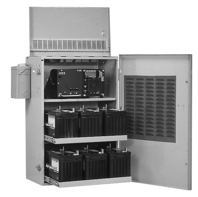
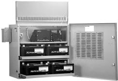
9 1.0 Introduction PWE/PME Series enclosures support distributed powering architectures in pole and ground-mount broadband applications. Ideal for use in all climates, each enclosure comes with a removable lockable door and easy opening lid. Standard features include a high-magnetic circuit breaker, duplex AC receptacle, and service power inserter. Key Features: Engineered for broadband powering applications All aluminum welded construction and durable powdercoat finish Agency certified to meet applicable industry standards Internal or external SUSE rated service entrance options Optional Battery Integration Tray (BIT) (PWE 3/6 only) Portable generator cabling access door Fig. 1-1, PWE-6 Enclosure with BIT 9
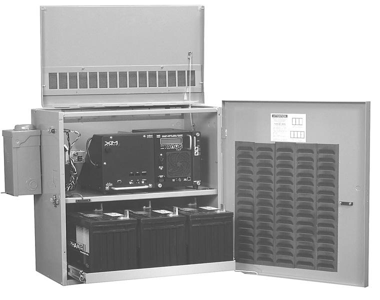
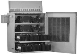
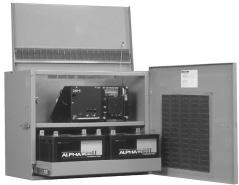
10 1.0 Introduction, continued 1.1 PWE/PME Series Enclosures PWE-4 PWE-3 PWE-8 PWE-6 PME PWE-9 PWE-D36 Fig. 1-2, PWE/PME Series Enclosures 10
11 1.0 Introduction, continued 1.2 PWE Enclosure Diagram NOTE: If the SPI is mounted in the location at the top of the enclosure, the SPI must be mounted vertically to allow space for other hardware. Front View Secondary SPI Mounting Location RF SPI Mounting Location Optional SPI Mounting Locations Optional Cooling Fan Primary SPI Mounting Location Duplex Receptacle Generator Access Door Power Supply Shelf Optional Battery Integration Tray ACI Optional Battery Slide Tray Assembly LRI Rear View Primary SPI Mounting Location Knockouts for Status Monitoring Secondary SPI Mounting Location Optional SPI Mounting Locations RF SPI Mounting Location Standard LRI Location (optional knockout located on right side) Optional ACI Location (knockouts located on left and right sides of enclosure) Optional External Breaker Box External Ground Lug Fig. 1-3, PWE-3 Enclosure (configurations may vary) 11
12 1.0 Introduction, continued 1.3 Optional Features Feature AC Indicator (ACI) Battery Heater Mat (BHM) Battery Mat Option (BMO) Battery Retaining Bar (BRB) External Coax Raceway (ECR) Enclosure Cooling Fan (ECF) Lightning Arrester-P+ (LA-P+) Local Remote Indicator (LRI) Module Retaining Cable (MRC) 15A and 25A Service Power Inserters (SPI) Solar Shield Kit (SSK) Storm Hood Kit (SHK) Tamper Switch (TMPR SW) Coax Surge Protector External Generator Connector Battery Slide Tray PWE High Security Device (PHSD) Ladder Bracket AlphaGEM BE-PWE Description The ACI verifies voltage output with a green light. Located next to the LRI lamp on the outside of PWE/PME Series enclosures, it is easily monitored from the ground. Because of its longer life, Alpha recommends the ACI- LL (long life) LED over the incandescent light bulb design. 60V and 90V models are available. The BHM is AC line operated and turns on at 40 F. It increases battery capacity in cold environments. Battery heater mats are available in 120Vac and 240Vac versions. The battery mat option provides additional battery cooling properties. The BRB provides additional security against batteries falling out of the enclosure. The ECR conceals and protects the coaxial cables outside the PWE-9 and PWE-D36 when ground-mounted. It is used in conjunction with the available pedestal mount, and is easily removed by unscrewing one wingnut. The ECF is a thermostat-controlled cooling system for PWE Series enclosures. Alpha recommends this option in extremely high-temperature environments. The fan automatically turns on at 140 F/60 C and off at 110 F/43 C. Replace the fan fuse with a 1/4" X 1-1/4" (6.4mm x 31.8mm), 5A, 250V fuse only (Alpha P/N ). The LA-P+ provides protection against voltage spikes caused by lightning and other power disturbances. It consists of three Metal Oxide Varistors (MOV), and is plugged directly into the enclosure s convenience outlet. The LA-P+ eliminates the need for hard-wired MOVs. Use the LA-P+ 120 in 120Vac applications, and the LA-P+ 240 in 240Vac applications. The LRI is a red lamp which indicates when the power supply is running in Standby Mode. A major alarm causes the lamp to flash, indicating service is required. Located on the outside of PWE/PME Series enclosures, it is easily monitored from the ground. The MRC attaches the XM Series 2 power supply to the PWE Series enclosure wall, preventing it from being knocked off of its shelf. A Service Power Inserter is required in all enclosures. The primary function of the SPI is to provide a connection point between the Alpha power supply and the cable load. Additionally, the SPI can bypass the power supply with a Service Power Supply. A 15A SPI is standard on PWE/PME Series enclosures. The SPI-25 (25A) is for use with higher output current power supplies. The Solar Shield Kit maintains a cooler environment within the PWE-8 enclosure, prolonging the life of the batteries and the power supply. By protecting the enclosure s skin, the shield reduces the amount of solar radiation absorbed by the enclosure (Note: For PWE-8 enclosure only). The SHK offers protection against dirt and snow ingress. Alpha recommends the use of the ECF (Enclosure Cooling Fan) in enclosures equipped with the SHK. The Tamper Switch is a magnetic door switch that connects to status monitoring equipment. Tamper Switches are available either as normally open (NO) or normally closed (NC) and set off an alarm if triggered. Provides surge suppression for power supply. Allows a permanent generator connection point. Option allows access to battery cabling without removing batteries. The PHSD is constructed of high grade stainless steel to provide physical security, corrosion resistance, and a strong visible deterrence. The PHSD is compatible with Alpha s PWE enclosures including; PWE 3, 6, and 9. The ladder bracket option (Alpha P/N ) easily attaches to all Alpha PWE Series enclosures and does not require a pole attachment point. The Ladder Bracket provides safe access for technicians servicing power supplies and batteries without the use of a bucket truck. The AlphaGEM Generator Expansion Module is temporarily installed to provide backup power during extended outage periods. See the AlphaGEM Installation Instructions, Alpha P/N C0. The BE-PWE expands battery backup capacity for PWE-3 enclosures. See the BE-PWE Technical Manual, Alpha P/N C0. 12
 eliminates the need for battery slide trays, and allows batteries to be individually installed or removed in PWE-3/6")

13 1.0 Introduction, continued 1.4 The Battery Integration Tray The optional Battery Integration Tray (BIT) eliminates the need for battery slide trays, and allows batteries to be individually installed or removed in PWE-3/6 enclosures. Each battery is connected directly to the BIT using modular 50A connectors. The BIT further improves wire management by pre-terminating connections for status monitoring voltage sense leads and for the AlphaGuard battery balancer. This eliminates the need to stack multiple wire terminations on each battery terminal, vastly simplifying battery replacement. Battery preventative maintenance is virtually eliminated when the BIT is used in conjunction with the new AlphaCell threaded-insert batteries, which do not have to be retorqued. Key Features: Improves enclosure wire management and reduces clutter Eliminates the need for sliding battery trays Reduces battery preventive maintenance costs Pre-wired for status monitoring and AlphaGuard, eliminating stacked leads Allows direct connection to the AlphaGen DC portable generator Factory installed option in PWE-3/6 enclosures Fig. 1-4, Battery Integration Tray (BIT) 13
 As an added safety precaution, the PWE series features a latch to hold the optional")

 (legacy enclosures); red: max. 82lbs (37.2kg) (standard for future enclosures). Opening the PWE Battery Slide Tray: 1. Push Up 2.")

14 1.0 Introduction, continued CAUTION! 1.5 PWE Battery Tray Latch Operation (optional) As an added safety precaution, the PWE series features a latch to hold the optional battery slide trays securely in place, in both open and closed positions. The latch automatically locks in place when the tray is pushed back in. The maxiumum weight of the battery slide tray is indicated by the color of the cap on the latch: Black: max. 72lbs (32.7kg) (legacy enclosures); red: max. 82lbs (37.2kg) (standard for future enclosures). Opening the PWE Battery Slide Tray: 1. Push Up 2. Pull Out PWE Tray Latch Location To open, push latch up and pull tray out. Tray automatically locks into open position. Opening the PWE-4 and PWE-8 Trays: To open, press tray latch in and pull tray out. Tray automatically locks in the open position. 2. Pull Out 1. Press In Closing the Tray on all PWE models: To unlock and close tray, press lock in toward tray and push tray closed. Press In When returned to the closed position, tray automatically locks back into place. Fig, 1-5, Opening the PWE Battery Slide Trays 14


 Battery Capacity Table 1-1, PME/PWE Enclosure Specifications Approx.")
15 1.0 Introduction, continued 1.6 PWE Lid Removal 1. Pull Out 2. Pull Up Fig, 1-6, PWE Lid Removal The lid can be completely removed by disconnecting retention strap 1.7 PWE/PME Enclosure Specifications Model PWE-3 PWE-4 PWE-6 PWE-8 PWE-9 PWE-D36 PME Dimensions (W x H x D) (in/mm) 24.25" x 24.5" x 14"/ 616 x 622 x " x 24.75" x 16"/ 768 x 629 x " x 36.75" x 14" 616 x 933 x " x 36.88" x 16" 768 x 937 x " x 47" x 14" 616 x 1194 x " x 47" x 14" 616 x 1194 x " x 24.5" x 14" 565 x 622 x 356 Shipping Weight (lb/kg) Battery Capacity Table 1-1, PME/PWE Enclosure Specifications Approx. Full System Weight (lb/kg) 38/ / / / / / / / / / / / / / PWE Legacy Models New PWE (Since April, 2002) Type II PWE Type I PWE 15
16 2.0 Installation CAUTION! Never transport the unit with installed batteries. Doing so can cause injury or damage to the enclosure and installed equipment. Install the batteries after you transport the unit to the site and secure it to the pole. Alpha recommends that you position the enclosure on the opposite side of the pole from traffic. This reduces the danger of falling equipment in the event that a pole is struck by an automobile. Mounting bolts must completely penetrate the wooden pole. Secure the bolts from the back with a large washer and nut. System installation at >5º angle not recommended. In case the unit is mounted off plumb, Alpha recommends the Battery Retaining Bar (p/n ) ATTENTION: The majority of poles belong to the local utility. Before you install an enclosure have both the location and mounting method approved by the utility. Because most codes require the enclosure to be located at a minimum height from the ground, always verify local height restrictions before you proceed. 2.1 Pole-mounting Wooden Pole Tools and Materials Required (customer supplied): Two (three for PWE-8, 9, D36) 5/8" (16mm) diameter machine bolts, length to suit pole Two 5/8" (16mm) diameter zinc plated flat washers Two 5/8" (16mm) diameter hex nuts (UNC thread) Auger or drill for boring 11/16" (17.5mm) diameter holes in the wooden pole Mallet or hammer Assorted sockets Tape measure Three-foot level Procedure: 1. Unpack the enclosure and galvanized brackets. 2. Mark the position for the upper bracket on the utility pole. From the installation side of the pole, and using a three-foot level to verify level, drill a 11/16" (17.5mm) hole completely through the pole. 16 NOTE: 3. Mark the location of the hole(s) for the lower bracket(s). For three-bracket enclosures, use the one-piece, 3-point bracket as a template. Spacing between the holes is as follows: Enclosure Distance (on center) (in/mm) PWE-3 and PME 18/457.2 PWE-4 15/381 PWE-6 30/762 PWE-8, PWE-9, PWE-D36 (three holes) 15 (30 total)/ 381 (762 total) 4. Using the three-foot level to verify drill angle, drill the 11/16" (17.5mm) hole or holes for the lower bracket or brackets from the installation side of the pole. Drill all holes from the enclosure side of the pole to ensure proper spacing.
17 2.1 Pole-mounting, continued Wooden Pole, continued 5. Secure the brackets to the pole using the 5/8" (16mm) machine bolts, washers, and nuts. 6. Lift the enclosure onto the brackets. It might be necessary to rock and pull the enclosure to properly seat it on the brackets. 7. Secure the enclosure to the brackets using the 3/8" x 3/4" (10mm x 19mm) hex bolts. 8. Make sure all nuts and bolts are fully tightened and the flanges of the brackets seat in the wood. 9. The enclosure is now ready for the utility connection, power module, and batteries. Cable Power Out 5/8" (16mm) Bolts Upper Mounting Bracket Nuts & Washers PWE-3 18" (457.2mm) Utility Power In (with BBX) Chassis Ground Lower Mounting Bracket 5/8" (16mm) Bolts Upper Mounting Bracket Nuts & Washers Lower Mounting Bracket PME 18" (457.2mm) Cable Power Out Chassis Ground Utility Power In Fig. 2-1, PWE/PME Series Wooden Pole Mounting 17
18 2.1 Pole-mounting, continued Concrete or Steel Pole Tools and Materials Required (customer supplied): Stainless steel banding (or equivalent), rated to support loaded enclosure and sized for pole diameter Assorted sockets Procedure: 1. Unpack the enclosure and galvanized brackets; turn the enclosure facedown on a soft surface. 2. Slide a bracket up through the enclosure s lower mounting bracket. The bracket s flanges must face away from the enclosure. Secure the lower mounting bracket using the 3/8" x 3/4" (10mm x 19mm) hex bolt included. 3. Position the upper mounting bracket on the pole and secure using banding. 4. Lift the enclosure onto the upper mounting bracket and pull downward to properly seat it. Center the enclosure on the pole. 5. Secure the lower mounting bracket on the pole using banding. Spacing between banding is as follows: Enclosure Distance (on center) (in/mm) PWE-3 and PME 18/457.2 PWE-4 15/381 PWE-6 30/762 PWE-8, PWE-9, PWE-D36 (three straps) 15 (30 total)/ 381 (762 total) 6. The enclosure is now ready for the utility connection, power module, and batteries. 18
19 2.1 Pole-mounting, continued Concrete or Steel Poles, continued 18" (457.2mm) 18" 18" 18" (457.2mm) Fig. 2-2, PWE/PME Series Steel or Concrete Pole-mounting 19
20 2.1 Pole-mounting, continued Enclosure Grounding: Pole-mount NOTE: Alpha recommends using the grounding method illustrated below. The grounding method may vary depending on local codes and other site-specific characteristics. External Grounding Lug #6 Bare Copper Wire Power Meter 1/2" (12.7mm) X 8' (2.4m) Copper Ground Rod Ground Wire Fig. 2-3, Enclosure Grounding for Pole-mount Configuration (with generator backup) 20
21 CAUTION! 2.2 Ground-mount Installation: PWE-4, PWE-8, PWE-9, PWE-D36 Never transport the unit with installed batteries. Doing so can cause injury to the installer, or damage the enclosure and equipment. Install the batteries after you transport the unit to the site and secure it to the pad. ATTENTION: It is the responsibility of the installer to meet the requirements of all applicable national and local codes. Alpha Technologies assumes no responsibility or liability for failure of the installer to comply with the requirements of all applicable local and national codes Pre-Installation Before choosing a location and beginning installation, consider the following: Provide adequate room for service personnel to remove the doors for battery installation and removal. Wherever possible, select a site that is above the 100-year flood plain and away from residences. Locate in the shade to minimize the effects of solar loading. Locate in an area with good airflow. Locate away from sprinkler systems or other sources of forced water. Locate out of the prevailing wind to minimize the buildup of snow or accumulation of wind-borne dust. Avoid locating the enclosure where it will be an obstruction or will inhibit visibility. Evaluate the soil conditions for suitability for the installation of the grounding system applicable to your particular installation. Is utility power cabling run to and terminated at the site? NOTE: The appropriate grounding method for a particular location depends on soil type, available space, local codes, NEC (National Electric Code), and other site-specific characteristics. 21
22 2.2 Ground-mount Installation: PWE-4, PWE-8, PWE-9, PWE-D36, continued Pre-Installation, continued Alpha Technologies, Inc. cannot anticipate all the ways a vehicle could threaten an installed system or the specific type of protection that is appropriate for a particular location. The following installation drawing for Alpha s Standby Power systems are general recommendations and not intended to be a specific guideline for protecting the equipment. The numbers of bollard posts (or other protection devices) depend upon equipment locations. PAD 10 (3m) SPRINKLER HEAD POSTS SIDEWALK Fig. 2-4, Ground-mount Positioning and Safety 22
23 NOTE: 2.2 Ground-mount Installation: PWE-4, PWE-8, PWE-9, PWE-D36, continued Enclosure Grounding: Ground-mount Alpha generally recommends using the grounding method illustrated below. However, the grounding method appropriate for a particular site depends on local codes, the NEC (National Electric Code), and other site-specific characteristics. Alpha Technologies recommends 5 ohms minimum ground resistance between enclosure and ground rods, in accordance with IEEE Powering and Grounding Electronic Equipment. Alpha Technologies assumes no responsibility or liability for failure of the installer to comply with the requirements of all applicable local and national codes. Where allowed, exothermic welding may be used as an alternative to Burndy clamps and connectors. CAUTION! Corrosion-proof, twenty-five-year connections suitable for direct burial must be used. Burndy YGHP58C2W-2TN or Equivalent Burndy YGHP58C2W-3 or Equivalent 2 Terminate at Service Entrance Ground Bar 4 Terminate at Enclosure Ground Bar 2 2' min. 8' (2.4m) Ground Rods 6 (1.8m) Apart (min.) 1 #2 AWG Fig. 2-5, Suggested Grounding Method Service Grounding (required) #6 bare copper wire from service entrance ground bar, with two 1/2" X 8' (12.7mm x 2.4m) copper ground rods, driven at least six feet (1.8 meters) apart. Lightning Protection (optional) Four 1/2" X 8' (12.7mm x 2.4m) copper ground rods, driven at least two feet from pad. #6 bare copper wire loop, at least 30" (762mm) below grade, and terminated at each ground rod. #6 bare copper wire from loop to enclosure ground bar in service entrance. 23
24 NOTE: 2.2 Ground-mount Installation PWE-4, PWE-8, PWE-9, PWE-D36, continued Ground-mount Installation, PWE-3, PWE-9 and PWE-D36 PWE-9 and PWE-D36 enclosures require a pedestal mount kit and Coax Raceway for ground installation. Pedestal kit part number: (gray); (white). Coax Raceway part number: B1 (gray); C3 (white). CAUTION! Tools and Materials Required (customer supplied): Four 1/2" (12mm) anchor bolts (Hilti-style recommended) Four 1/2" (12mm) stainless steel washers 2' X 3' (.6m x.9m) continuous vapor barrier (e.g. 30 lb. felt, neoprene pond liner, or a heavy grade tar paper) Hammer drill 1/2" (12mm) drill bit 1/2" (12mm) wrench Metal punch Mallet or hammer Torque wrench Tape measure A 25+ year continuous vapor barrier must be placed between the pedestal and the pad to prevent moisture ingress and corrosion caused by metal-to-concrete contact. Procedure: 1. Place the vapor barrier material on concrete pad. 2. Using the pedestal as a template, mark the vapor barrier material in the locations of the four anchor bolts holes. 3. Drill 1/2" (12mm) holes through the vapor barrier and into the pad at the four marked anchor points. 4. Position the pedestal over holes and insert anchor bolts. Torque the anchor bolts to bolt manufacturer specifications. If Hilti-style bolts are used, torque until head pops. 5. On the enclosure, remove the four 3/8" (9.5mm) diameter knock-outs located beneath the lower battery shelf. 6. Lift the enclosure onto the pedestal. Slide the lower battery tray to the fully extended and locked position. Align the four enclosure mounting holes with the mounting holes on the top of the pedestal. Secure the enclosure to the pedestal using the provided 1/4" (19mm) hardware. Torque to 75 in-lbs (8.5 Nm). 7. Trim away excess vapor barrier material. 8. The enclosure is now ready for the utility connection, power module, and batteries. 24
 3\" (76.2mm) Pedestal Anchor Holes Utility Sweep 21.38\" (543mm) (on center) 9\" (228.6mm) (on center) 3.8\" (96.")
25 2.2 Ground-mounting PWE-4, PWE-8, PWE-9, PWE-D36, continued PWE-9 and PWE-D36 Ground-mount Installation, continued Pad Outside of Pedestal Inner Flange on Bottom of Pedestal Enclosure Mounting Holes Coax Raceway Mounting Coax Raceway Pedestal Anchor Holes Coax Sweep 3.25" (82.6mm) 3" (76.2mm) Pedestal Anchor Holes Utility Sweep 21.38" (543mm) (on center) 9" (228.6mm) (on center) 3.8" (96.5mm) Fig. 2-6, PWE-3, PWE-6, PWE-9, and PWE-D36 Enclosure Pedestal (Not Shown) Fig. 2-7, Location of (4) Knockouts for Enclosure-to-Pedestal Mounting (Note: two locations are not shown in picture) 25

26 NOTE: 2.2 Ground-mount Installation, PWE-4, PWE-8, PWE-9, PWE-D36, continued PWE-4 and PWE-8 Ground-mount Installation PWE-4 and PWE-8 enclosures require a ground mount kit for ground installation. Alpha P/N This kit only fits enclosures manufactured after April See Fig to identify compatible enclosures. Tools and Materials Required (customer supplied): Four 1/2" (12mm) anchor bolts (Hilti style recommended) Four 1/2" (12mm) stainless steel washers Hammer drill 1/2" (12mm) drill bit 1/2" (12mm) wrench Metal punch Mallet or hammer Torque wrench Tape measure Procedure: CAUTION! 1. Turn the enclosure face down on a soft, non-abrasive surface. Remove the six knock-outs on bottom of enclosure using a hammer and a metal punch. Metal from knockouts must be removed from the enclosure before installing batteries or electronics. 2. Secure the mounting brackets to the enclosure with the six bolts provided. Insert the bolts from inside the enclosure. Use the holes in the battery tray to access the front bolt locations (See Fig. 2-8). Tighten the bolts to 240 in-lbs (27.1 Nm). 3. Use the enclosure with mounting brackets installed as a template and mark the four anchor bolt locations on the pad. 4. Drill the holes for the four anchor bolts in the pad. 5. Mount the enclosure to the pad using the 1/2" (12mm) anchor bolts and washers. Torque bolts to manufacturer s specifications. If Hilti style bolts are used, torque until head pops. 6. The enclosure is now ready for the utility connection, power supply, and batteries. Fig. 2-8, Access Holes for Front Bracket Mounting Locations 26
 11\" (279.4mm) Front of Enclosure Fig.")
27 2.2 Ground-mount Installation, PWE-4, PWE-8, PWE-9, PWE-D36, continued PWE-4 and PWE-8 Ground-mount Installation, continued Anchor Bolt Locations Fig. 2-9, Ground-mounting Brackets, Installed 27" (685.8mm) 11" (279.4mm) Front of Enclosure Fig. 2-10, Enclosure Ground-mount Footprint NOTE: This kit is only compatible with enclosures manufactured after April Array of Louvers Covering Front Door No louvers on sides Compatible Enclosures Incompatible Enclosures Fig. 2-11, Enclosures Manufactured Before and After April
28 WARNING! 2.3 Connecting Utility Power ONLY qualified personal should connect the utility power. Power must be connected in compliance with local electrical codes, and common safety practices must be observed. ATTENTION: Connection to utility power must be approved by the local utility before installing the power supply. UL and NEC require that a service disconnect switch (UL listed) be provided by the installer and be connected between the power source and the Alpha power supply. Connection to the power supply must include an appropriate service entrance weather head. Utility power enters the enclosures through a 1-1/8" (28.6mm) opening in the bottom of the PME series, and in the rear of the PWE series, or through an optional breaker box. The enclosures accept a standard electrical fitting. A high-magnetic trip circuit breaker must be used in order to accommodate the high-inrush currents normally associated with the start-up of ferroresonant transformers (400A, no-trip, first-half cycle). Do not replace this circuit breaker with a conventional service entrance circuit breaker. Alpha recommends Square D circuit breakers for 120V installations, and HACR (heating and air-conditioning) breakers for 240V installations. Alpha Technologies offers a high-magnetic Square D circuit breaker and a BBX option (a UL Listed service entrance). Contact your local sales representative for more information. Description Alpha Part Number Square D Part Number 240V Installation HACR (15A) QO V Installation High-Magnetic (20A) QO120HM 120V Installation High-Magnetic (15A) QO115HM BBX External Service Disconnect QO2-4L70RB BBX External Service Disconnect QO8-16L100RB Table 2-1, Service Entrance Circuit Breaker Requirements NOTE: Alpha recommends 12AWG wiring to accommodate a 90V power supply. 28
29 2.3 Connecting Utility Power, continued In most cases, the following configurations qualify for service entrance use. However, conflicting codes may apply. Always contact your local utility to verify that the wiring conforms to applicable codes. 240Vac Service (XM Power Supply; XM Series for PWE-4 and PWE-8) 120Vac 20A Service (XM Power Supply) 120Vac 15A Service (XM Power Supply) Enclosures used with the XM Series 2, model or , are equipped with a 240Vac duplex receptacle to provide power to the power supply and peripheral equipment. This NEMA 6-15R receptacle is protected by a 2-pole, common-trip, 15A circuit breaker located inside the service entrance. Wiring is typically 14AWG, per NEC code. A grounding clamp is located on the enclosure facilitates dedicated grounding. Enclosures used with the XM Series 2, model , are equipped with a 120Vac duplex receptacle to provide power to the power supply and peripheral equipment. This NEMA 5-20R receptacle is protected by a 2-pole, common-trip, 20A circuit breaker located inside the service entrance. Wiring is typically 12AWG, per NEC code. A grounding clamp is located on the enclosure facilitates dedicated grounding. Enclosures used with the XM Series 2, model 615, are equipped with a 120Vac duplex receptacle to provide power to the power supply and peripheral equipment. This NEMA 5-15R receptacle is protected by a single-pole, 15A, High- Magnetic circuit breaker located inside the service entrance. Wiring is typically 14AWG, per NEC code. A grounding clamp is located on the enclosure facilitates dedicated grounding. 29
30 2.3 Connecting Utility Power, continued L1 (Black) To Utility L2 (Red) To Utility L1 (Black) Copper Ground Wire #8 AWG min. Neutral (White) Copper Ground Wire #8 AWG min. Neutral (White) Breaker Grounding Point Made to Enclosure Wall Neutral Bus Breaker Grounding Point Made to Enclosure Wall Neutral Bus L1 (Black) 120Vac To Enclosure Receptacle L1 L2 240Vac To Enclosure Receptacle Fig. 2-12, Typical Service Entrance Wiring 120Vac 15A Receptacle, 5-15R 120Vac 20A Receptacle, 5-20R Neutral (White) L1 (Black) Neutral (White) L1 (Black) Ground (Green) Ground (Green) 240Vac 15A Receptacle, 6-15R L2 (Red) L1 (Black) Ground (Green) Fig. 2-13, Typical Receptacle Wiring 30
31 2.3 Connecting Utility Power, continued Ground Line 2 Line 1 ON OFF ISE 240V 15A Neutral Ground Line ON ISE 120V 20 A OFF Neutral Ground Line ON ISE 120V 15A OFF Fig. 2-14, Typical ISE (Internal Service Entrance) Receptacle Wiring 31
32 2.3 Connecting the Utility Power, continued Ground Line 2 Line 1 Neutral Ground Line ON ON OFF OFF BQO 240V, 15A BQO 120V, 20A Neutral Ground Line 2 Line 1 Neutral Ground Line ON ON ON OFF OFF OFF BQO 240V, 120V BQO 120V, 20A Dual Receptacle, Dual Breaker Fig. 2-15, Typical BQO (Breaker Quad Option) Receptacle Wiring 32
 as a cost-effective alternative to building an assembly on-site.")
33 2.3 Connecting the Utility Power, continued Cable Output Service Drop External Grounding Lug Utility Power Input 5' 5.5' 6" (1.7m) Meter Service Entrance NOTE: Fig. 2-16, PWE Pole-mount Configuration Alpha offers a Meter Convenience Assembly (MCA) as a cost-effective alternative to building an assembly on-site. The MCA is a factory-configured, pole-mount meter and service disconnect with integral bracket that makes installation simple and consistent. Product Description Part Number FBX (20A fuse kit included) A BBX A BBX Alternate Meter (e.g. Universal Meter Base) Contact Alpha Representative 33
34 2.3 Connecting Utility Power, continued Meter Socket Clamp Ground Line 1 Line 2 Neutral Fig. 2-17, Meter Wiring Line 1 Ground Bus Circuit Breaker (Square D Q0220) O N 2 0 O F F Line 2 Neutral Neutral Bus Line 2 Line 1 Circuit Breaker (Square D Q0220) Ground ON 20 OFF Line 2 Neutral Neutral Bus Line 2 Ground Neutral Line 1 Ground Clamp Neutral Ground Line 1 Ground Clamp #8 AWG (Min.) Copper Ground Wire Fig. 2-18, 240Vac CSA Service Entrance Wiring #8 AWG (Min.) Copper Ground Wire Fig. 2-19, 240Vac UL Service Entrance Wiring 34
35 2.4 Connecting the Coaxial Cable Coaxial Cable Surge Protector Installation Instructions Alpha recommends using coaxial surge suppression for enclosure protection. The Coax Surge Protector with Ground Block (Alpha P/N ) includes 75 ohm surge suppressor, mounting hardware, and waterproofing grommet. Required Tools: Drill with 3/16" (4.8mm) bit. For older enclosures a 3/4" (19mm) bit is also needed. Phillips screwdriver 3/8" (9.5mm) socket and driver 1. Drill two 3/16" (4.8mm) holes 1½" (38.1mm) apart (indicated locations are recommended). Newer enclosures have center punch marks on the left and right side of the enclosure. 2. Attach the surge protector to the inside of the enclosure wall with provided hardware. For proper grounding, ensure the included star washers come in contact with the enclosure wall. 3. On newer enclosures, knock out one of the 3/4" (19mm) knockouts located in the upper rear of the enclosure. On older enclosures, drill a 3/4" (19mm) hole in desired location. Press the grommet into the hole from the outside of the enclosure. 4. Cut center of grommet and insert coaxial cable. 5. Pull cable back to form seal. 3/4" (19mm) Knockouts (for grommet) 6.5" to 7.25" (165.1mm to 184.2mm) 4" (101.6mm) 1.5" (38.1mm) Service Customer SERVICE CUSTOMER Grommet Installation ¾" Cut center 35
36 WARNING! 2.4 Connecting the Coaxial Cable, continued Connecting the Service Power Inserter (SPI) Disconnect all power sources from the SPI (Service Power Inserter) before removing its cover. Verify that the SPI is disconnected from both the utility power and the power supply before beginning procedure. Primary SPI Mounting Location PWE Enclosures Secondary SPI Mounting Location PME Enclosures SPI RF SPI Mounting Location Power Suppy Output (Coaxial Cable) SPI Power Suppy Output (Coaxial Cable) Fig. 2-20, SPI Mounting Locations Procedure: 1. Disconnect the SPI from all power sources. 2. Remove the two screws securing the cover to the SPI chassis. Remove the cover, exposing the circuit board and seizure screw assembly. Seizure Screw Output Port Stinger Seizure Screw Assembly SPI Cover Coaxial Termination Fig. 2-21, SPI Fig. 2-22, SPI (side view) 36
. 5.")
37 CAUTION! NOTE: 3. Screw the Coaxial Termination into Output Port on bottom of SPI, inserting the stinger into the seizure screw assembly. 4. Tighten seizure screw to 35 in-lbs (4 Nm). To prevent arcing and failure of the unit, insert the coaxial cable completely into the seizure screw assembly and tightened the seizure screw to 35 inch-pounds (4 Nm). 5. Replace SPI cover and reinstall screws. 6. Verify switch on top of SPI is on the ON position. 2.5 Battery Installation Battery Date Code Usage and Identification Every battery contains a DATE CODE. This code is usually located near the positive (+) terminal, and must be recorded in the maintenance log. If you use batteries other than those installed by Alpha, consult the batteries manufacturer s documentation for date code type and placement. The date code scheme and location varies depending on the age of the battery used. Month: June Year: 2005 Fig. 2-23, Battery Date Code 37
38 WARNING! 2.5 Battery Installation, continued Battery Installation Procedure To prevent arcing, never allow live battery cables to make contact with the enclosure. Disconnect battery leads, or wrap the cable lugs with electrical tape. CAUTION! Threaded insert terminals require the use of 3/4" (19mm) bolts. The use of 1" (25.4mm) bolts will seriously damage the battery. The only exception is the terminal with the large spacer for the in-line fuse link. See section for details. NOTE: In battery configurations made up of multiple battery strings, Alpha strongly recommends the use of in-line fuses. Procedure: CAUTION! 1. Place the batteries on the enclosure s battery slide tray or battery shelf. The correct arrangement of the batteries on the tray or shelves varies between enclosure models. See the Figs through 2-31 for the correct battery arrangement for each model. Leave a minimum of one inch of ventilation space between the batteries. 2. To make identification and record keeping easier, number and label the batteries. Record each battery s number and date code in the power supply maintenance log. 3. Using the battery arrangement diagrams as a reference, connect the batteries in series to achieve 36Vdc or 48Vdc. Refer to the diagrams for the location of the optional in-line fuses. Torque terminal connections according to battery recommendations (see battery label for AlphaCell batteries). 4. Check the polarity and voltage of the battery cable connector with a voltmeter to verify correct connections. Do Not connect the battery string or strings to the power supply at this time. 5. The power supply battery charger collects battery temperature compensation information with a Remote Temperature Sensor (RTS) attached to one of the batteries. Refer to the diagrams to determine which battery to attach the RTS to. Attach the RTS about 1/3 of the way up from the battery s base with a strong adhesive tape. Route the RTS connector into the power supply compartment. Do Not connect the RTS to the power supply at this time. Recheck the polarity and voltage of the battery cable connector before proceeding. Connecting the battery string or strings to the power supply with incorrect polarity will cause a short-circuit, and possible equipment damage. 6. Route the battery cable connector into the power supply compartment. Do Not connect to the batteries to the power supply at this time. 38
 to each battery, and to matching connector on the Battery Integration Tray (BIT).")
 (Alpha P/N 744-346-20). The BRB mounts in factory installed spring clips.")
39 2.5 Battery Installation, continued Connecting the Battery Integration Tray (PWE 3/6 Only) 1. Connect the battery cable kits (Alpha P/N ) to each battery, and to matching connector on the Battery Integration Tray (BIT). Torque to the battery manufacturer's specification (for AlphaCell batteries see battery label). 2. If applicable, secure the batteries with the optional Battery Retaining Bar (BRB) (Alpha P/N ). The BRB mounts in factory installed spring clips. External Generator Connector Power Supply Connection External Generator Connection Cabling Battery Retaining Bar Prewired AlphaGuard Shelf Battery Retaining Bar Individual Battery Connectors (3 per tray) Fig. 2-24, Battery Integration Tray Connections 39
40 NOTE: 2.5 Battery Installation, continued Battery Terminal Connections Various types of batteries with different mounting styles and hardware may be shipped with the system. ALWAYS refer to the battery manufacturer s specifications for correct mounting hardware and torque requirements. Use only the hardware and torque recommended by the battery manufacturer. There are two types of battery terminals: the newer, threaded insert terminals, and the older, flag terminals. The following drawings and pictures are for illustrative purposes only. CAUTION! Threaded Insert Terminals Threaded insert terminals require the use of 3/4" (19mm) bolts. The use of 1" (25.4mm) bolts will seriously damage the battery. The only exception is the terminal with the large spacer for the in-line fuse link. 3/4" (19mm) x 1/4-20 Bolt Split Washer Flat Washer Battery Sense Cable Battery Cable Battery Terminal Nut Split Washer Flat Washer Battery Cable In-Line Fuse Link Flat Washer 1" (25.4mm) or 3/4" (19mm) x 1/4-20 Bolt Fuse 1" (25.4mm) x 1/4-20 Bolt Split Washer Flat Washer Spacer Battery Terminal Fig. 2-25, Threaded Insert Battery Terminal Connections 40
41 2.5 Battery Installation, continued Battery Terminal Connections, continued Flag Terminals Battery Sense Cable Flat Washer Split Washer Flat Washer Nut 1" x 1/4-20 Bolt Battery Cable Battery Terminal Nut Split Washer Flat Washer Battery Cable 1" (25.4mm) x 1/4-20 Bolt Split Washer Flat Washer In-Line Fuse Link Flat Washer 1" (25.4mm) or 3/4" (4.8mm) x 1/4-20 Bolt Spacer Battery Terminal Fig. 2-26, Flag Battery Terminal Connections 41
42 2.5 Battery Installation, continued Battery Wiring Diagrams Battery Cable Connector (to XM2 Power Supply) R E D (+) B L A C K (-) Temperature Probe (Connected to XM2) Black (-) Red (+) RTS (Taped to side of battery) In-line Fuse (optional) Battery Cable Connector (to XM2 Power Supply) Fig. 2-27, PWE-3 (without BIT) and PME Battery Wiring Diagram R E D (+) B L A C K (-) Temperature Probe (Connected to XM2) RTS (Taped to side of battery) Black (-) Red (+) In-line Fuse (optional) Fig. 2-28, PWE-4 Battery Wiring Diagram 42
43 CAUTION! 2.5 Battery Installation, continued Battery Wiring Diagrams, continued If using the optional slide tray, zip-tie the negative black wire to the center battery interconnection cable. This will prevent the wire interfering with slide tray closure. Battery Cable Connector (to XM2 Power Supply) R E D (+) B L A C K (-) Temperature Probe (Connected to XM2) Red (+) Black (-) Zip-tie together Upper Tray 3A 2A 1A RTS (Taped to side of battery) Zip-tie to enclosure flange In-line Fuse (optional) 3B 2B 1B Zip-tie to enclosure flange Lower Tray In-line Fuse (optional) Fig. 2-29, PWE-6 Battery Wiring Diagram (without BIT) 43
44 2.5 Battery Installation, continued Battery Wiring Diagrams, continued Battery Cable Connectors (to XM2 Power Supplies) R E D (+) B L A C K (-) R E D (+) B L A C K (-) Black (-) Red (+) Red (+) 3A 2A 1A Upper Tray RTS (Taped to side of battery) Temperature Probe (Connected to XM2) Black (-) In-line Fuse (optional) 3B 2B 1B Lower Tray RTS (Taped to side of battery) In-line Fuse (optional) Fig PWE-D36 Battery Wiring Diagram 44
45 2.5 Battery Installation, continued Battery Wiring Diagrams, continued Battery Cable Connector (to XM2 Power Supply) R E D (+) B L A C K (-) Temperature Probe (Connected to XM2) RTS (Taped to side of battery) Red (+) Black (-) 3A 1A Upper Tray 4A 2A In-line Fuse (optional) 3B 1B Lower Tray 4B 2B In-line Fuse (optional) Fig. 2-31, PWE-8 Battery Wiring Diagram 45
OBE-3-FT Outdoor Series
 OBE-3-FT Outdoor Series Installation Guide WARNING: Serious Personal Injury Securely mount the enclosure to the ground to prevent tipping. Failure to do so could lead to serious injury or death. Wear appropriate
LPE Enclosure. Installation and Operation Manual. LPE Enclosure Effective: 05/2010. member of The
 LPE Enclosure Installation and Operation Manual LPE Enclosure Effective: 05/2010 member of The Group Power Alpha Technologies LPE Enclosure Installation and Operation Manual 031-302-B0-001, Rev. A Effective
Fiber Backhaul Enclosure
 Fiber Backhaul Enclosure Fiber Backhaul Enclosure (FBE) Installation Manual Effective: July 2009 Alpha Technologies Power Alpha Technologies Fiber Backhaul Enclosure Installation Manual 021-081-B0-001,
OBE-3 Outdoor Series
 OBE-3 Outdoor Series Installation Guide WARNING: Serious Personal Injury Securely mount the enclsoure to the ground to prevent tipping when the battery trays are used. Failure to do so could lead to serious
MASTERsine Inverter PXA Series Installation Guide
 Backup Power System Expert TM MASTERsine Inverter PXA Series Installation Guide Important Safety Instructions IMPORTANT: Read and save this Installation Guide for future reference. This chapter contains
Powernode Systems Broadband Power Systems
 Powernode Systems Broadband Power Systems Cost-effective, compact power solutions. Choice of minimum footprint design or low profile designs. Multiple power supplies, battery strings, natural gas or propane
Fiber Power Enclosure. Installation Manual. Effective: October 2015
 Fiber Power Enclosure Installation Manual Effective: October 2015 Safety Notes Alpha considers customer safety and satisfaction its most important priority. To reduce the risk of injury or death and to
APX Series. Non-standby Power Supply. APX Series. Installation and Operation Manual. Effective: April 2015 Alpha Technologies
 APX Series Non-standby Power Supply APX Series Installation and Operation Manual Effective: April 05 Alpha Technologies Power Alpha Technologies APX Series Non-standby Power Supply 06-030-B0-005, Rev C
Installation and Operating Procedures For C&D Technologies TRUE Front Access TEL Series Batteries
 RS-2046 Installation and Operating Procedures For C&D Technologies TRUE Front Access TEL Series Batteries FOLLOW MANUFACTURER S PUBLISHED INSTRUCTIONS WHEN INSTALLING, CHARGING AND SERVICING BATTERIES.
VRLA Batteries. Battery Installation And Start up Guide
 TECHNICAL MANUAL 41-7525 VRLA Batteries 26-206 Ampere-Hour Capacity Battery Installation And Start up Guide (For Rack Mounted Systems) 41-7525/0514/CD www.cdtechno.com Table of Contents 12V VRLA Battery
Owner's/Installation Manual
 Owner's/Installation Manual Power Management Module (PMM) and Starter Kit NOTE: The starter kit must be purchased and installed prior to individual PMM usage. Model Numbers: 00686-0 PMM 00699-0 PMM WITH
Electric Vehicle Charging Station
 EVoReel Electric Vehicle Charging Station INSTALLATION GUIDE AND USER MANUAL Model: Dual Output Pedestal Mount 30A EVoReel EVSE Model Numbers: With Basic EVSE: EV072-400-002A; With Intelligent ievse: EV072-410-002A;
SMU-F Valve Regulated Lead Acid Battery
 AlphaCell TM SMU-F Valve Regulated Lead Acid Battery Installation and Operation Manual AlphaCell TM SMU-F Valve Regulated Lead Acid Battery Effective: December 2009 Alpha Technologies Power Alpha Technologies
Installation Instructions for Load Management Kit A051C329
 Instruction Sheet 12-2014 Installation Instructions for Load Management Kit A051C329 1 Introduction The information contained within is based on information available at the time of going to print. In
INSTALLATION GUIDE AND USER MANUAL
 Electric Vehicle Charging Station INSTALLATION GUIDE AND USER MANUAL SAE J1772 AC Level 2 EVSE Model: 30A EVoCharge EVSE Wall Mount P/N: EV072-300-001A Version 2.0 IMPORTANT Read this manual thoroughly
MODEL ELC-12/40-CVM-D BATTERY CHARGER
 NATIONAL RAILWAY SUPPLY MODEL ELC-12/40-CVM-D BATTERY CHARGER Installing, Operating and Service Instructions for the ELC-12/40-CVM-D Solid State Charger PLEASE SAVE THESE IMPORTANT SAFETY AND OPERATING
Installing Power Components
 This chapter provides instructions on how to install and reinstall power components in the Cisco NCS 4016 chassis. It also covers connecting and disconnecting power and powering on the chassis. The Cisco
Model: OBD-L On-Board-Diagnostics II Memory Saver Detector
 Model: OBD-L On-Board-Diagnostics II Memory Saver Detector OWNERS MANUAL IMPORTANT SAFETY INSTRUCTIONS SAVE THESE INSTRUCTIONS This manual will show you how to use your memory saver detector safely and
! "! User Manual Myers Power Products CTEP/G Manual 6/2009
 !"! User Manual Myers Power Products CTEP/G Manual 6/2009 Chapter 1 General Information The Myers Pwer Products (Myers) CTEP/G Series Power Supply Enclosures provide protection for power supplies/ups
SOS SERIES SOS1 SOS2. Spares On Site Battery Cabinet Installation Guide rEV3
 Atlantic Battery Systems 1065 Market Street Paterson, NJ 07513 Phone: (800) 875-0073 Fax: (973) 523-2344 sales@atbatsys.com www.atbatsys.com SOS1 SOS2 SOS SERIES Spares On Site Battery Cabinet Installation
MODEL ELC-12/60-D BATTERY CHARGER
 *32198* NATIONAL RAILWAY SUPPLY Installing, Operating and Service Instructions for the 12/60 Solid State Charger MODEL ELC-12/60-D BATTERY CHARGER PLEASE SAVE THESE IMPORTANT SAFETY AND OPERATING INSTRUCTIONS
INSTALLATION GUIDE AND USER MANUAL
 Electric Vehicle Charging Station INSTALLATION GUIDE AND USER MANUAL Model: 30A EVoCharge EVSE Model Number: EV072-300-001A Product Safety Certification: UL and cul Listed Description: SAE J1772 AC Level
Dual-Lite Trident TRF 40 Wide Battery Cabinet 20-40kVA Systems USER MANUAL
 Dual-Lite Trident TRF 40 Wide Battery Cabinet 20-40kVA Systems USER MANUAL 755-00020-DL 5/17/2017 2 755-00020-OEM R01 TABLE OF CONTENTS 1. Important Information About This Manual... 4 1.1 Manual Symbols...
Installation and Operating Procedures For C&D Technologies TRUE Front Access TEL Series Batteries
 RS02046 Installation and Operating Procedures For C&D Technologies TRUE Front Access TEL Series Batteries FOLLOW MANUFACTURER S PUBLISHED INSTRUCTIONS WHEN INSTALLING, CHARGING AND SERVICING BATTERIES.
SMU-F. AlphaCell TM. Technical Manual. Valve Regulated Lead Acid Battery. AlphaCell SMU-F Valve Regulated Lead Acid Battery Effective: February 2007
 AlphaCell TM SMU-F Valve Regulated Lead Acid Battery Technical Manual AlphaCell SMU-F Valve Regulated Lead Acid Battery Effective: February 2007 Alpha Technologies AlphaCell SMU-F Valve Regulated Lead
Illuminator System Series CIII
 Illuminator System Series CIII 4.8 kw 16.7 kw Installation Guide 44 South Commerce Way, Bethlehem, PA 18017 1-800-526-5088 (610) 868-3500 Fax: (610) 868-8686 Service: (610) 868-5400 www.myerspowerproducts.com
INSTALLATION AND OPERATION MANUAL
 INSTALLATION AND OPERATION MANUAL California Proposition 65 Warning: Batteries, battery posts, terminals and related accessories contain lead and lead compounds, and other chemicals known to the state
Installation Instructions and User Manual For. 100 Watt Inverter Power System
 Installation Instructions and User Manual For 100 Watt Inverter Power System Installation Instructions and User Manual For LiteGear 100 Watt Inverter Power System Warning: THIS PRODUCT CONTAINS CHEMICALS
SunLink PV System Disconnect with Arc Fault Detection Installation and Operations Manual
 Combiner Box Installation & Operations Manual SunLink PV System Disconnect with Arc Fault Detection Installation and Operations Manual TABLE OF CONTENTS Notices and Safety Precautions Pages 1-2 Combiner
AUTO CHARGE 4000 MODEL #: LOW PROFILE CHARGER AUTOMATIC DUAL OUTPUT BATTERY CHARGER INSTRUCTION MANUAL
 INSTRUCTION MANUAL AUTO CHARGE 4000 LOW PROFILE CHARGER AUTOMATIC DUAL OUTPUT BATTERY CHARGER Unit supplied with this display MODEL #: 091-89-12 INPUT: 120 Volt, 50/60 Hz, 5 Amps OUTPUT: 45 Amps File:
Solar module user manual Conergy PM 225P-250P
 Solar module user manual Conergy PM 225P-250P 1 Introduction 1.1 Short description Conergy PM modules are solar modules for installation in photovoltaic systems. 1.2 About this manual 1.2.1 Subject of
model ps600 Address all communications and shipments to: FEDERAL SIGNAL CORPORATION
 MODEL: PS600 HZ: 60 A model ps600 installation and service manual for federal model ps600 FEDERAL SIGNAL CORPORATION POWER SUPPLY VOLTS: SERIES: 120VAC FEDERAL SIGNAL CORPORATION UNIVERSITY PARK, IL. U.S.A.
Copyright 2012 DelSolar Co. Ltd MQWRD installation manual-iec Ver. 1.4
 INSTALLATION MANUAL IEC Version www.delsolarpv.com Copyright 2012 DelSolar Co. Ltd MQWRD-01-14--installation manual-iec Ver. 1.4 Content General information 1 Safety precaution for installing solar PV
Users Manual. Defender 1 8.0KW to 14.0KW Online Emergency Lighting Inverter. Technical Manual # Revision B
 Users Manual Defender 1 8.0KW to 14.0KW Online Lighting Inverter Technical Manual #018-0102-01 Revision B Phone: 1.877.DSPM.POWER 1.877.377.6769 Fax: 909.930.3335 Website: www.dspmanufacturing.com E-Mail:
Users Manual. Cobra Plus Stand-By Emergency Lighting Inverter. Technical Manual # Revision B
 Users Manual Cobra Plus Stand-By Lighting Inverter Technical Manual #018-0110-01 Revision B Phone: 1.877.DSPM.POWER 1.877.377.6769 Fax: 909.930.3335 Website: www.dspmanufacturing.com E-Mail: techsupport@dspmanufacturing.com
Nature Power Inverters. True Sinewave Inverter Modified Sinewave Inverter. Owner s Manual
 Version 1.1 Version 2 Nature Power Inverters True Sinewave Inverter Modified Sinewave Inverter Owner s Manual!!!!!!!!!!! 38304 38204 For safe and optimum performance, the Power Inverter must be used properly.
Illuminator System Series CM
 Illuminator System Series CM.5 kw 2.0 kw Installation Guide 44 South Commerce Way, Bethlehem, PA 18017 1-800-526-5088 (610) 868-3500 Fax: (610) 868-8686 Service: (610) 868-5400 www.myerspowerproducts.com
CAT-1 Series 3. Installation Guide. The Valley Group, Inc. 871 Ethan Allen Hwy. Suite 104 Ridgefield, CT 06877
 CAT-1 Series 3 Installation Guide The Valley Group, Inc. 871 Ethan Allen Hwy. Suite 104 Ridgefield, CT 06877 (203) 431-0262 (203) 431-0296 FAX tvg@cat-1.com Installation of Load Cells for CAT-1 Systems
AlphaCell SMU. Technical Manual. AlphaCell SMU. Effective: January Alpha Technologies
 AlphaCell SMU Technical Manual AlphaCell SMU Effective: January 2007 Alpha Technologies Power Alpha Technologies AlphaCell SMU Technical Manual, Rev. A Effective Date: January, 2007 Copyright 2007 Alpha
FLUSH EYES IMMEDIATELY WITH WATER. GET MEDICAL HELP FAST. SULFURIC ACID CAN CAUSE BLINDNESS OR SEVERE BURNS.
 8A & 8G BATTERY INSTALLATION AND OPERATING INSTRUCTIONS This manual is intended to be a guide to optimize battery performance for multiple cyclic & float applications. Consult applicable User Manuals for
OWNER S MANUAL. Model YUA2AMPCH 2 AMP Dual-Bank Automatic Battery Charger & Maintainer READ ENTIRE MANUAL BEFORE USING THIS PRODUCT
 Model YUA2AMPCH 2 AMP Dual-Bank Automatic Battery Charger & Maintainer Certified by California BCS Regulations OWNER S MANUAL READ ENTIRE MANUAL BEFORE USING THIS PRODUCT READ ENTIRE MANUAL BEFORE USING
Sentinel Field Satellite Controller
 WARNING HIGH VOLTAGE 115V M AP Sentinel Field Satellite Controller Installation Instructions Important: For your protection and the safety of the product user, please comply with all Caution and Warning
P Original Series Cargo Van Lift Mounting Instructions Fullsize Ford Van present. Preparing the Gate
 Fullsize Ford Van- 1992-present Preparing the Gate 1. Remove the mounting hardware which is banded to the liftgate. 2. Verify mounting kit (Figure 1 and Table 1). S-400-40 STRAP VAN MOUNTING EAR BENT BRACKET
Galaxy VM. Battery Breaker Box Installation 09/
 Galaxy VM Battery Breaker Box Installation 09/2016 www.schneider-electric.com Legal Information The Schneider Electric brand and any registered trademarks of Schneider Electric Industries SAS referred
AM / AP SERIES. Standby Power Supplies. AM 660 Series AM 960 Series. Technical Manual Alpha Technologies
 AM / AP SERIES Standby Power Supplies AM 660 Series AM 960 Series Technical Manual 1996 Alpha Technologies The AM / AP Series Standby Power Supply IMPORTANT SAFETY INSTRUCTIONS CONTAINED IN THIS MANUAL
AUTOMATIC BEST BATTERY SELECTOR INSTALLATION & OPERATION BBS-4800 BBS-4800E
 AUTOMATIC BEST BATTERY SELECTOR INSTALLATION & OPERATION BBS-4800 BBS-4800E SENS part no: 101312 Document revision: K DCN No. 107455 Date 4/2/18 1840 Industrial Circle Longmont, CO 80501 Fax: (303) 678-7504
Installation and Operation Instructions SERVICE BY QUALIFIED PERSONNEL ONLY
 ELI-S-600 120 Volt ELI SERIES EMERGENCY LIGHTING INVERTERS Installation and Operation Instructions! IMPORTANT SAFEGUARDS! WHEN USING ELECTRICAL EQUIPMENT, BASIC SAFETY PRECAUTIONS SHOULD ALWAYS BE FOLLOWED,
Installation, Maintenance, and Operation Manual
 GTX TM UNIT SUBSTATION Installation, Maintenance, and Operation Manual Rev.3 03-10-15 Marina Electrical Equipment, Inc. 100 Warwick Court Williamsburg, VA 23185 Toll Free: 1-855-258-3939 Fax: 1-757-258-3988
Vehicle battery BATTERY WARNING SYMBOLS BATTERY CARE
 Vehicle battery BATTERY WARNING SYMBOLS On the battery label, the warning signs are as follows: BATTERY CARE No smoking, no naked flames, no sparks. The battery may emit explosive gas. Keep away from children
Model: SE-4020-CA Automatic Battery Charger
 OWNERS MANUAL Model: SE-4020-CA Automatic Battery Charger PLEASE SAVE THIS OWNERS MANUAL AND READ BEFORE EACH USE. This manual will explain how to use the battery charger safely and effectively. Please
Installation And Operation Instructions
 Installation And Operation Instructions For PS Series Mini-Inverter Power Systems Models: PS-55-LP, PS-110-HP, PS-110-LP, PS-220-HP Surface (-S), Recessed (-R) and Ceiling T-Grid (-T) Mounted Versions
Sentinel Field Satellite Controller Metal Pedestal, Plastic Pedestal and Wall Mount Models Installation Instructions
 WARNING HIGH VOLTAGE 115V 4 M AP Sentinel Field Satellite Controller Metal Pedestal, Plastic Pedestal and Wall Mount Models Installation Instructions Important: For your protection and the safety of the
Installation Instructions Studio Makeup Station
 Installation Instructions Studio Makeup Station 30" and 36" Models 5-light 30" Studio Makeup Station 8-light 30" Studio Makeup Station 6-light 36" Studio Makeup Station 9-light 36" Studio Makeup Station
AUXILIARY BATTERY BOX INSTALLATION INSTRUCTIONS
 AUXILIARY BATTERY BOX INSTALLATION INSTRUCTIONS The original TOMMY GATE hydraulic lift Assembling the Auxiliary Battery Box 1. Remove the cover from the auxiliary battery box by removing the two nuts and
SCC-MPPT Solar Charge Controller
 Table 3: Charging voltage for 4 types of battery Battery Battery 12V battery system 24V battery system Type Type Code Bulk Floating Bulk Floating Vented 01 14.3 V 13.2 V 28.6 V 26.4 V Sealed 02 14.3 V
Installation Instructions for Remote Mount HMI 211 Display Panel Kit A045J206
 Instruction Sheet 7-2013 Installation Instructions for Remote Mount HMI 211 Display Panel Kit A045J206 1 Introduction The information contained within is based on information available at the time of going
IMPORTANT SAFETY INSTRUCTIONS
 1163714 1.5 AMP 12VOLT TRICKLE 1.5 AUTOMATIC AMP AUTOMATIC TRICKLE 1.5 AMP AUTOMATIC 12V12VOLT BATTERY CHARGER IMPORTANT SAFETY INSTRUCTIONS 1. SAVE THESE INSTRUCTIONS This product offers a wide range
SCC-MPPT Solar Charge Controller
 Solar Charge Controller Quick Guide 200W 300W 400W 600W 850W V. 2.2 1. Introduction solar charge controller uses PWM-based DSP controller to keep the batteries regulated and prevent batteries from overcharging
PUMP PLUS 2000 PLC MODEL #: PP AUTOMATIC DUAL OUTPUT BATTERY CHARGER INSTRUCTION MANUAL
 INSTRUCTION MANUAL PUMP PLUS 2000 PLC AUTOMATIC DUAL OUTPUT BATTERY CHARGER Supplied with Dual Bar Graph Display MODEL #: 091-237-12-PP INPUT: 120 Volt, 60 Hz, 3.5 Amps OUTPUT BATTERY 1 and 2: 15 or 18
Technical Manual MPS48-7F/T. Alpha Technologies
 TM Technical Manual MPS48-7F/T Effective: January 2008 Alpha Technologies Power Alpha Technologies MPS48-7F/T Technical Manual 021-511-B0-004, Rev. D Effective Date: January 2008 Copyright 2008 Alpha Technologies,
High Frequency SineWave Guardian TM
 High Frequency SineWave Guardian TM 380V 480V INSTALLATION GUIDE FORM: SHF-IG-E REL. January 2018 REV. 002 2018 MTE Corporation High Voltage! Only a qualified electrician can carry out the electrical installation
Power Inverter 400 MW Owner s Manual
 Power Inverter 400 MW 1204 Owner s Manual For safe and optimum performance, the Power Inverter must be used properly. Carefully read and follow all instructions and guidelines in this manual and give special
AUTOMATIC BEST BATTERY SELECTOR INSTALLATION & OPERATION BBS-1600 BBS-1600E
 AUTOMATIC BEST BATTERY SELECTOR INSTALLATION & OPERATION BBS-1600 BBS-1600E SENS part no: 101314 Document revision: H DCN No. 107395 Date 11/22/17 1840 Industrial Circle Longmont, CO 80501 Fax: (303) 678-7504
Installation And Operation Instructions
 Installation And Operation Instructions For MPS Series Micro-Inverter Power Sytems Lead Calcium Battery Models: MPS-32 and MPS-55 Nickel Cadmium Battery Models: MPS-20 and MPS-35 Surface (-S), Recessed
GSL Electronics Modified Sine Wave Power Inverters
 GSL Electronics Modified Sine Wave Power Inverters Congratulations on choosing one of our Modified Sine Wave Inverters for your application. There are 6 models in the range, which will meet most of your
BATTERY SAVER LOW RIPPLE HO
 INSTRUCTION MANUAL BATTERY SAVER LOW RIPPLE HO LOW RIPPLE POWER SUPPLY / AUTOMATIC LOAD SWITCH FOR 12VDC VEHICLE SYSTEMS MODEL #: 091-195-12 INPUT: 120 Volt, 50/60 Hz, 4.5 Amps RMS OUTPUT: 13.2 Volts DC,
INSTALLATION MANUAL. Melink Corporation (513) Revision
 Revision") INSTALLATION MANUAL Revision 130711 Table of Contents Step Installation Contractor Page 1 Install System Controller Electrical 4 2 Install Variable Frequency Drive Electrical 6 3 Install Touchpad Mechanical
INSTALLATION MANUAL Revision 130711 Table of Contents Step Installation Contractor Page 1 Install System Controller Electrical 4 2 Install Variable Frequency Drive Electrical 6 3 Install Touchpad Mechanical
LPC 20 MODEL #: LOW PROFILE CHARGER AUTOMATIC SINGLE OUTPUT BATTERY CHARGER INSTRUCTION MANUAL
 INSTRUCTION MANUAL LPC 20 LOW PROFILE CHARGER AUTOMATIC SINGLE OUTPUT BATTERY CHARGER Unit supplied with one of these displays MODEL #: 091-207-12 INPUT: 120 Volt, 50/60 Hz, 7 Amps OUTPUT: 20 Amps File:
Pump Sentry. Models 812 PS & 1612 PS INSTALLATION INSTRUCTIONS
 Pump Sentry Models 812 PS & 1612 PS INSTALLATION INSTRUCTIONS The Pump Sentry is an innovative power station designed to operate your pump during a power outage. When properly installed, it will provide
SCC-MPPT Solar Charge Controller
 Table 4: Alarm point for low battery voltage table Model Alarm point SCC-MPPT-300 10.5 V SCC-MPPT-600 21.0 V Table 5: Charging hour table for reference Battery Capacity To 90% capacity @ 25A charging current
Solar Charge Controller
 Table 3: Charging voltage for 4 types of battery Battery Type Battery Type Code SC-600W MPPT Bulk Voltage Floating Voltage Vented 01 28.6 V 26.4 V Sealed 02 28.6 V 26.8 V Gel 03 28.6 V 27.4 V NiCd 04 28.6
A+ Battery Backup Power Supply For use with Hydromatic model B-A1/BV-A1
 Unit Installation and Service Manual A+ Battery Backup Power Supply For use with Hydromatic model B-A1/BV-A1 NOTE! To the installer: Please make sure you provide this manual to the owner of the pumping
AUTO CHARGE D PUMP PLUS
 INSTRUCTION MANUAL AUTO CHARGE D PUMP PLUS AUTOMATIC DUAL OUTPUT BATTERY CHARGER Designed Specifically for Vehicles with DDEC ENGINES MODEL #: 091-9-DPP INPUT: 120 Volt, 60 Hz, 8 Amps OUTPUT VEHICLE BATTERY:
AUTO CHARGE D2 MODEL #: AUTOMATIC TRIPLE OUTPUT BATTERY CHARGER INSTRUCTION MANUAL
 INSTRUCTION MANUAL AUTO CHARGE D2 AUTOMATIC TRIPLE OUTPUT BATTERY CHARGER Designed Specifically for Vehicles with DDEC ENGINES MODEL #: 091-74-12 INPUT: 120 Volt, 60 Hz, 8 Amps OUTPUT VEHICLE BATTERY 1
LIGHTNING PROTECTION UNIT (LPU)
") LIGHTNING PROTECTION UNIT (LPU) Photovoltaic Lightning Protection Device Installation and Operation Manual SPECIALTY CONCEPTS, INC. 8954 Mason Ave. Chatsworth, CA 91311 USA MODELS COVERED: LPU-50, LPU-150,
LIGHTNING PROTECTION UNIT (LPU) Photovoltaic Lightning Protection Device Installation and Operation Manual SPECIALTY CONCEPTS, INC. 8954 Mason Ave. Chatsworth, CA 91311 USA MODELS COVERED: LPU-50, LPU-150,
AUTO CHARGE DUAL MODEL #: AUTOMATIC DUAL OUTPUT BATTERY CHARGER INSTRUCTION MANUAL. Ph: Fax:
 INSTRUCTION MANUAL AUTO CHARGE DUAL AUTOMATIC DUAL OUTPUT BATTERY CHARGER MODEL #: 091-145-12 INPUT: 120 Volt, 50/60 Hz, 3.5 Amps OUTPUT BAT 1: 10 Amps OUTPUT BAT 2: 10 Amps File: IM_091-145-12_revb.indd
Technical Manual. DLM Module. This manual should remain with the unit.
 Technical Manual DLM Module This manual should remain with the unit. Safety Rules SAVE THESE INSTRUCTIONS! Read the following information carefully before attempting to install, operate or service this
650 Series Cargo Van Lift Mounting Instructions Ford Transit (Standard Roof) 2015-Present
 2015-Present") TOMMY GATE OWNER'S / OPERATOR'S MANUAL 650 Series 650 LB Capacity 650 Series Cargo Van Lift Mounting Instructions Ford Transit (Standard Roof) 2015-Present Installing the Base Plate 1. Examine the interior
TOMMY GATE OWNER'S / OPERATOR'S MANUAL 650 Series 650 LB Capacity 650 Series Cargo Van Lift Mounting Instructions Ford Transit (Standard Roof) 2015-Present Installing the Base Plate 1. Examine the interior
INSTALLATION MANUAL.
 INSTALLATION MANUAL D6M_BxA Series : D6M_B1A / D6M_B2A / D6M_B3A / D6M_B5A D6M_AxA Series : D6M_A1A / D6M_A2A / D6M_A3A / D6M_A5A D6P_BxA Series : D6P_B1A / D6P_B2A / D6P_B3A / D6P_B5A D6P_AxA Series :
OPERATOR S MANUAL JUMP STARTER. and DC Power Source. Model No CAUTION: Sears, Roebuck and Co., Hoffman Estates, IL U.S.A.
 OPERATOR S MANUAL JUMP STARTER and DC Power Source Model No. 71489 CAUTION: Read and follow all Safety Rules and Operating Instructions before Every Use of this Product. SAVE THESE INSTRUCTIONS. Sears,
DC TO AC POWER INVERTER
 DC TO AC POWER INVERTER 12V / 24V / 48Vdc Input 115V / 230Vac Output 150W ~ 6000W Output cont. L-Series User Manual Before install and use your Inverter, read the User Manual and safety instructions. Cooler
Guardian Battery Charger Series. Installation and Operations Manual Section 75
 Guardian Battery Charger Series Installation and Operations Manual 00-02-0615 02-29-08 Section 75 In order to consistently bring you the highest quality, full featured products, we reserve the right to
CTFRP Series Power Supplies
 CTFRP Series Power Supplies Ferroresonant Non-Standby Power Supplies User Manual Myers Power Products 6/2013 CTFRP Series Manual Chapter 1 General Information The Myers CTFRP Series Power Supply provides
Automatic Battery Charger Switching mode with Micro-controlled Input: Vac / Output: 12Volt DC
 Automatic Battery Charger Switching mode with Micro-controlled Input:220-260Vac / Output: 12Volt DC User s Manual and Important Safety Information Model: OC-SW121080 / OC-SW121160 / OC-SW121210 FEATURES
LMI Watt Models
 LMI 300-600 Watt Models Service Questions Call: 800-451-9423 INSTALLATION AND OPERATING INSTRUCTIONS IMPORTANT SAFEGUARDS When using electrical equipment, basic safety precautions should always be followed,
C&D Technologies, Inc. Dynasty Division 900 East Keefe Avenue Milwaukee, WI53212 Phone: Fax:
 , C&D Technologies, Inc. Dynasty Division 900 East Keefe Avenue Milwaukee, WI53212 Phone: 800-396-2789 Fax: 414-961-6506 Form 41-7525 (Rev.6100) Printed in U.S.A. Inter-tier, Inter-Unit Inter-row Cables,
Battery Power Inverters
 Battery Power Inverters Renogy 500W 1000W 2000W Pure Sine Wave Inverter Manual 2775 E. Philadelphia St., Ontario, CA 91761 1-800-330-8678 1 Version 1.4 Important Safety Instructions Please save these instructions.
AUTO CHARGE 4000 MODEL #: AUTOMATIC DUAL OUTPUT BATTERY CHARGER INSTRUCTION MANUAL. Ph: Fax:
 INSTRUCTION MANUAL AUTO CHARGE 4000 AUTOMATIC DUAL OUTPUT BATTERY CHARGER MODEL #: 091-89-12 INPUT: 120 Volt, 50/60 Hz, 8 Amps OUTPUT BATTERY CHARGER: 40 Amps OUTPUT BATTERY SAVER: 5 Amps File: IM_091-89-12_reve.indd
Apollo Solar Inverter Switchgear Module Installation Manual Rev 1.2 Page 1
 Apollo Solar Inverter Switchgear Module Installation Manual Rev 1.2 Page 1 Model/Configuration: ISM 120/240, ISM 120/240-T80, ISM 120, ISM 120-T80 The Apollo Solar Inverter Switchgear Module (ISM) meets
Alcatel-Lucent 7310 DC Metro Cell AWS (B4) Kit MC-DBR1, MC-DBR2, MC-DBR3, MC-DBR4, MC-DBR5. Installation Manual
 Kit MC-DBR1, MC-DBR2, MC-DBR3, MC-DBR4, MC-DBR5. Installation Manual") Alcatel-Lucent 7310 DC Metro Cell AWS (B4) Kit MC-DBR1, MC-DBR2, MC-DBR3, MC-DBR4, MC-DBR5 Installation Manual ALCATEL-LUCENT DC METRO CELL AWS (B4) KIT INSTALLATION INSTRUCTIONS Document Information Identification
Alcatel-Lucent 7310 DC Metro Cell AWS (B4) Kit MC-DBR1, MC-DBR2, MC-DBR3, MC-DBR4, MC-DBR5 Installation Manual ALCATEL-LUCENT DC METRO CELL AWS (B4) KIT INSTALLATION INSTRUCTIONS Document Information Identification
How to Install and Remove a standard Teletrac Transceiver.
 How to Install and Remove a standard Teletrac Transceiver. April 27 2010 Draft: 001.fc.4_10.doc Introduction. This document is comprised of two independent sections. The first section addressed all the
AUTO CHARGE 12 HO MODEL #: MODEL #: MODEL #: AUTOMATIC SINGLE OUTPUT BATTERY CHARGER INSTRUCTION MANUAL
 INSTRUCTION MANUAL AUTO CHARGE 12 HO AUTOMATIC SINGLE OUTPUT BATTERY CHARGER MODEL #: 091-170-6 MODEL #: 091-170-12 MODEL #: 091-170-24 File: IM_091-170-xx_revd.indd Rev: D Revised By: MFG Date: 10-23-2013
BR62 Battery Rack Installation, Operation, & Maintenance Manual
 BR62 Battery Rack Installation, Operation, & Maintenance Manual 8/28/2012 2 755-00046 R02 Copyright 2012 C&C Power, Inc. All rights reserved. C&C Power, Inc. 395 Mission Street Carol Stream, IL 60188 www.ccpower.com
Sentry Battery Charger. Installation and Operations Manual Section 75
 Sentry Battery Charger Installation and Operations Manual 00-02-0616 03-03-08 Section 75 In order to consistently bring you the highest quality, full featured products, we reserve the right to change our
RT Series Step Down Transformer for RT Series UPS 6-10kVA UL Input Vac Output Vac User Guide
 RT Series Step Down Transformer for RT Series UPS 6-10kVA UL Input 208-240 Vac Output 208-120 Vac User Guide UNLESS SPECIFICALLY AGREED TO IN WRITING, SELLER (A) MAKES NO WARRANTY AS TO THE ACCURACY, SUFFICIENCY
Monicon Instruments Co., Ltd. CHR-1285/2485 CHR-1285/2485 BATTERY CHARGER
 CHR-1285/2485 BATTERY CHARGER TEL:886-4-2238-0698 FAX:886-4-2238-0891 Web Site:http://www.monicon.com.tw E-mail:sales@monicon.com.tw Copyright 2007 Monicon Instruments Co., Ltd. All right reserved. Contents
Cab Kit Installation Instructions
 Low Speed Vehicles (LSV) Electric Vehicles: Carryall Carryall 6 Cab Kit Installation Instructions Publication 050770 These instructions apply to the following kit: 0670 Edition Code 008E09D GENERAL INFORMATION
LPC 40 MODEL #: LOW PROFILE CHARGER WITH PLC AUTOMATIC SINGLE OUTPUT BATTERY CHARGER INSTRUCTION MANUAL
 INSTRUCTION MANUAL LPC 40 LOW PROFILE CHARGER WITH PLC AUTOMATIC SINGLE OUTPUT BATTERY CHARGER Unit supplied with one of these displays MODEL #: 091-200-12 INPUT: 120 Volt, 50/60 Hz, 5 Amps OUTPUT: 40
User Manual. Solar Charge Controller 3KW
 User Manual Solar Charge Controller 3KW 1 CONTENTS 1 ABOUT THIS MANUAL... 3 1.1 Purpose... 3 1.2 Scope... 3 1.3 SAFETY INSTRUCTIONS... 3 2 INTRODUCTION... 4 2.1 Features... 4 2.2 Product Overview... 5
PUMP PLUS 1000 PLC MODEL #: PP AUTOMATIC SINGLE OUTPUT BATTERY CHARGER INSTRUCTION MANUAL
 INSTRUCTION MANUAL PUMP PLUS 1000 PLC AUTOMATIC SINGLE OUTPUT BATTERY CHARGER Unit supplied with one of these displays MODEL #: 091-215-12-PP INPUT: 120 Volt, 60 Hz, 3.5 Amps OUTPUT BATTERY 1 and 2: 15