INSTALLATION AND OPERATION MANUAL
|
|
|
- Damian Thompson
- 6 years ago
- Views:
Transcription

1 INSTALLATION AND OPERATION MANUAL California Proposition 65 Warning: Batteries, battery posts, terminals and related accessories contain lead and lead compounds, and other chemicals known to the state of California to cause cancer and birth defects or other reproductive harm. Wash hands after handling.
2 TABLE OF CONTENTS Safety Precautions Protective Equipment...3 Procedures...3 Receiving & Storage Receiving Inspection...3 Unpacking...3 System Shipment...4 Storage...4 Installation General...4 Grounding...4 Electric Code for Maintenance Access...4 Floor Anchoring & Module Arrangements...4 Hardware Torque Requirement...4 System Installations Module Installation...4 Cell Installation...5 Electrical Connection Connector Assembly...6 Terminal Assembly Top Termination Side Termination Final Assembly Check Procedure...10 Safety Shield Assembly...10 System Operations Charger Voltage...11 Operating Temperatures...11 Cell Voltage...11 Rectifier Ripple Voltage...11 Record Keeping...11 Maintenance Annual Inspection...12 Battery Cleaning...12 Capacity Testing...12 Cell/Sleeve Removal Procedure...12 Acid Volumes & Weights...12 Battery Maintenance Report HIGH VOLTAGE... RISK OF SHOCK. DO NOT TOUCH UNINSULATED TERMINALS OR CONNECTORS. SHIELD EYES. EXPLOSIVE GASES CAN CAUSE BLIND- NESS OR INJURY. DO NOT REMOVE VENT VALVE. WARRANTY VOID IF VENT VALVE IS REMOVED. California Proposition 65 Warning: DANGER NO SPARKS FLAMES SMOKING SULFURIC ACID CAN CAUSE BLINDNESS OR SEVERE BURNS. FLUSH EYES IMMEDIATELY WITH WATER. GET MEDICAL HELP FAST. VENTILATE WELL WHEN IN AN ENCLOSED SPACE AND WHEN CHARGING. SEE INSTALLATION, MAINTENANCE AND OPERATION INSTRUCTIONS FOR IMPORTANT SAFETY PRECAUTIONS. Batteries, battery posts, terminals and related accessories contain lead and lead compounds, and other chemicals known to the state of California to cause cancer and birth defects or other reproductive harm. Wash hands after handling. BATTERIES AND OTHER RELATED PARTS CONTAIN LEAD WARNING: Battery posts, terminals and related accessories contain lead and lead compounds, chemicals known to the State of California to cause cancer and reproductive harm. Batteries also contain other chemicals known to the State of California to cause cancer. WASH HANDS AFTER HANDLING! Form No: 1314 Rev. 8/08 Must be posted in workplace near batteries. 2
3 SAFETY PRECAUTIONS Although all valve-regulated batteries have the electrolyte immobilized within the cell, the electrical hazard associated with batteries still exists. Work performed on these batteries should be done with the tools and the protective equipment listed below. Valve-regulated battery installations should be supervised by personnel familiar with batteries and battery safety precautions. Protective Equipment To assure safe battery handling, installation, and maintenance, the following protective equipment should be used: 1. Safety glasses or face shield 2. Acid-resistant gloves 3. Protective aprons and safety shoes 4. Proper lifting devices 5. Properly insulated tools Procedures The following safety procedures should be followed during installation: (Always wear safety glasses or face shield when working on or near batteries.) 1. These batteries are sealed and contain no free electrolyte. Under normal operating conditions, they do not present any acid danger. However, if the battery jar or cover is damaged, acid could be present. Sulfuric acid is harmful to the skin and eyes. Flush affected area with water immediately and consult a physician if splashed in the eyes. 2. Prohibit smoking and open flames, and avoid arcing in the immediate vicinity of the battery. 3. Do not wear metallic objects, such as jewelry, while working on batteries. Do not store un-insulated tools in pockets or tool belt while working in vicinity of battery. 4. Keep the top of the battery dry and clear of all tools and other foreign objects. 5. Provide adequate ventilation (per IEEE standard 1187 and/or local codes) and follow recommended charging voltages. 6. Extinguishing media: Class ABC extinguisher. Note: CO 2 may be used but not directly on the cells due to thermal shock and potential cracking of cases. 7. Never remove or tamper with the pressure relief valves. Warranty void if vent valve is removed. 8. Inspect all flooring and lifting equipment for functional adequacy. 9. Adequately secure battery modules, racks, or cabinets to the floor. 10. Connect support structures to ground system in accordance with applicable codes. 11. The below IEEE Standards contain additional information. Other standards may be relevant to your specific application. IEEE 1184 Guide for Batteries for UPS Systems IEEE 1187 Recommended Pratice for Installation Design of VRLA Batteries. IEEE 1188 Recommended Pratice for Maintenance, Testing, of VRLA Batteries. IEEE 1189 Selection of VRLA Batteries for Stationary Applications HIGH VOLTAGE... RISK OF SHOCK. DO NOT TOUCH UNINSULATED TERMINALS OR CONNECTORS. NO SPARKS FLAMES SMOKING DANGER SHIELD EYES. EXPLOSIVE GASES CAN CAUSE BLINDNESS OR INJURY. SEE INSTALLATION, MAINTENANCE AND OPERATION INSTRUCTIONS FOR IMPORTANT SAFETY PRECAUTIONS. California Proposition 65 Warning: SULFURIC ACID CAN CAUSE BLINDNESS OR SEVERE BURNS. FLUSH EYES IMMEDIATELY WITH WATER. GET MEDICAL HELP FAST. VENTILATE WELL WHEN IN AN ENCLOSED SPACE AND WHEN CHARGING. DO NOT REMOVE VENT VALVE. WARRANTY VOID IF VENT VALVE IS REMOVED. Batteries, battery posts, terminals and related accessories contain lead and lead compounds, and other chemicals known to the state of California to cause cancer and birth defects or other reproductive harm. Wash hands after handling. Fig. 1-1 RECEIVING & STORAGE Receiving Inspection Upon receipt, and at the time of actual unloading, each package should be visually inspected for any possible damage or electrolyte leakage. If either is evident, a more detailed inspection of the entire shipment should be conducted and noted on the bill of lading. Record receipt date, inspection data, and notify the carrier of any damage. Unpacking 1. Always wear eye protection. 2. Check all batteries for visible defects such as cracked containers, loose terminal posts, or other unrepairable problems. Batteries with these defects must be replaced. 3. Check the contents of the package against the packaging list. Report any missing parts or shipping damage to your East Penn agent or East Penn Mfg. Co. immediately. 4. Never lift the batteries by the terminal posts. 5. When lifting batteries, the proper equipment is needed such as a forklift or a portable crane. Always check the lifting capacities of the equipment being used and never lift more than one module and/or cell at a time. 3
4 System Shipment Battery System will be received in two separate shipments. First shipment will be modules and base (Figure 1). Second shipment will be cells in sleeves (Figure 2) and system hardware on individual skid. Electric Code for Maintenance Access Refer to ANSI/NFPA-70 National Electric Code for access and working space requirements around the battery. A minimum of 36" aisle space is recommended in front of the battery for service and inspection. Floor Anchoring & Module Arrangements See East Penn Mfg. Co. s schematic diagram illustration. One is supplied with each shipment. If it cannot be located, contact East Penn Mfg. Co. for a copy. Refer to your delivery number, located on the packing slip. This will aid in obtaining the proper drawing. Hardware Torque/Retorque Requirements Bolt Size Torque/Retorque Figure 1 Figure 2 1/ ft lb Nm 3/ ft lb 33.8 Nm 1/ in lb 14.1 Nm Storage 1. Cells should be stored indoors in a clean, level, dry and cool location. Recommended storage temperature is 0 F to 90 F ( 18 C to 32 C). 2. Stored lead-acid batteries self discharge and must be charged six months from the date of manufacture to prevent permanent performance degradation. Record dates and conditions for all charges during storage. 3. Recommended charge during storage is at a constant voltage of 0.05 volts per cell greater than recommended float votage for 24 hrs. Reference Operating Temperature chart on page Do not store beyond 12 months. 5. Store in horizontal position only. SYSTEM INSTALLATIONS Module Installation Assemble system per the following details. All parts should be verified against packaging list. Report any missing parts. 1. Remove floor-mounting base support from the top of the modules. Base is bolted to module assembly, upside down. INSTALLATION General Caution should be taken when installing batteries to ensure no damage occurs. The battery cabinet, tray, rack, etc. shall be inspected for sharp edges that could cause damage to the battery casing. Batteries shall not be dropped, slid, or placed on rough or uneven surfaces such as tray lips or grated flooring. Mishandling of batteries could result in equipment damage or human injury. East Penn will not be liable for damage or injury as a result of mishandling or misuse of the product. Grounding When grounding the battery system, proper techniques should be applied per electrical standards, such as NEC and/or local codes. Two.201 diameter x.750 center holes are provided in back of each module to accept a #6 x.750 center compression grounding lug. The holes must be tapped for a 1/4-20UNC thread and paint must be removed for a proper grounding pad location.* *Note: Battery system and/or individual module grounding, if required, is the installer s responsibility. 2. Position bases, consult included layout diagram for required configuration. Bases are required to be level with the floor and each other prior to installing modules. 3. Anchor holes can be marked and drilled with bases in place. All anchor holes in base (16 per base) are required to be used to meet seismic requirements. Consult local building codes for anchor bolt requirements. Anchor bolts not included. 4

5 4. Remove hardware holding modules together and holding modules to skid. Hardware removed from modules will be reused to attach modules to bases and to each other. Hardware holding modules to skid will not be reused. CAUTION: Never lift more than one module at a time with the supplied lifting slings. 5. Install modules onto bases using supplied lifting straps. Consult below diagram for proper sling attachment and lifting. Consult included layout diagram for module position. 7. Joining plates are to be placed at the rear of the modules at the top of the stacks. One joining plate is to be used at the junction of two modules. Use 1/2-13 x 1.25" hardware to install the plates. Hardware should be torqued after module installation is complete. Torque bolts to 100 ft-lb (135.5 Nm). 8. Module layout should be compared to system layout diagram and all hardware should be checked for proper torque before proceeding. Consult Hardware Torque Requirements (pg 4) for proper torque values. Cell Installation Assemble system per the following: All parts should be verified against packaging list. Report any missing parts. All hardware included on separate pallet marked Accessories. 1. Removing cells from skid. a. Remove metal strapping. Caution should be taken to avoid metal strapping coming in contact with battery posts. b. Remove screws from wood spacer. Cell retainer bolts should not be removed. DO NOT REMOVE 6. Install modules onto bases, limit two modules per base. Bolt modules to bases and to each other using supplied hardware (1/2-13 x 1.50") and ones removed from modules during dismantling. Twelve bolts per module. Stack to stack level shall be verified. Torque bolts to 100 ft-lb (135.5 Nm). REMOVE WOOD SCREWS & DISCARD c. Install cells into modules. Consult layout drawing for cell location and polarity. Attach cell to module using (4) 3/8-16 x 1.25" hardware*. Torque bolts to 25 ft-lb (33.8 Nm). *Shield brackets to be installed prior to bolt assembly per page 6, Section d. 5
6 d. Safety Shield Brackets are to be installed at the outside corners of each module (4 per module). Consult below detail for locations. Use 3/8-16 x 1.25" hardware to install brackets. Torque bolts to 25 ft-lb (33.8 Nm). Care should be taken when installing cells that lifting device does not damage brackets. Connector Kit A 4CU / 10CU kit will require Kit WPC a 4CU connector package for the vertical connections - 4 2CU / 6CU <= 4500 connectors per vertical connection (2 per side) with JMP1409 4CU / 10CU > 4500 bolt assembly and a 10CU connector package for the horizontal connections - 10 connectors per horizontal connection (5 per side) with JMP1453 bolt assembly. The below examples represent a 2CU / 6CU Connector Kit. VERTICAL CONNECTION ELECTRICAL CONNECTION Connector Assembly 1. The contact surfaces of each individual post on every cell have been cleaned and coated with a thin film of no-ox-id A grease at the factory. Assure the contact surfaces are free of dust or dirt prior to assembly. 2. Installation and direction of the battery post hardware is important. Consult the below diagram for clarification. 3. High Rate applications will require multiple connectors to be used per battery post. The vertical connections will require a different quantity of connectors than the horizontal connections. Consult Accessory Kit description to confirm correct connector kit and review the Connector Package Detail drawing, included with the system layout drawing to ensure proper connection quantities. HORIZONTAL CONNECTION TERMINAL ASSEMBLY Top Termination Consult layout diagram for termination location. 1. Install terminal plate bracket to the top of the module. Use 1/2-13 x 1.50" hardware. Install loosely for future alignment. 2. Remove cell sleeve bolts directly behind location of terminal plate. 3. Replace flat washer with cap washer. Re-install 3/8-16 x 1.25" into cell sleeve with safety shield bracket (if required). Torque hardware at 25ft-lb (33.8Nm). Install rubber caps over bolts. 4. Install terminal plate to battery posts using 1/4-20 x 1.75" hardware. Attach terminal plate to terminal plate bracket. Terminal Plate Bracket may have to be moved in order to be flush with the terminal plate. 5. Torque 1/2-13 hardware at 100ft-lb (135.5 Nm) and 1/4 20 hardware at 125 in-lb (14.1 Nm). Bolt Assembly Package Connector Package Bolt Assembly Bolt Assembly Part Number 2CU 1/4-20 x 1.75" JMP1435 4CU 1/4-20 x 2.00" JMP1409 6CU 1/4-20 x 2.25" JMP CU 1/4-20 x 2.75 JMP1453 A 2CU / 6CU kit will require a 2CU connector package for the vertical connections - 2 connectors per vertical connection (1 per side) with JMP1435 bolt assembly and a 6CU connector package for the horizontal connections - 6 connectors per horizontal connection (3 per side) with JMP1451 bolt assembly. 6
7 6. Top terminal plate designed to use up to 0.50" dia. bolt and a maximum 1.75" centers, 2 hole lug. Lug hardware not included. HOLE LAYOUT COMPLETE ASSEMBLY Side Termination Consult layout diagram for termination location. 1. Remove cell sleeve bolts (3/8-16 x 1.25") from the module (retain for later use). 2. Install plastic Side Terminal Bracket in location where bolts were removed in previous step. Use 3/8-16 x 1.25" bolts from Step 1. Bolts should be installed loosely for future adjustments. 3. Safety Shield Bracket may also be required to be installed. They are to be installed in front of the side terminal bracket. 4. Install side terminal plate to terminal plate bracket using 1/4-20 x 1.00" hardware. Bolts should be installed loosely for future adjustments. 5. Install side terminal connectors to battery posts using 1/4-20 bolts. Bolts should be installed loosely for future adjustments. 6. Connect side terminal plate to side terminal plate connectors. Side terminal bracket and side terminal connectors may have to be adjusted to ensure plate and connectors are flush. Use 1/4-20 x 1.50" hardware. 7. After all parts are installed and alignment is confirmed, torque all bolts: 3/8-16 to 25ft-lb (33.8Nm) and 1/4-20 to 125 in-lb (14.1 Nm). 7
8 8. Side Terminal Plate is designed to use up to 0.50" dia. bolt and a maximum 1.75" centers, 2 hole lug. Plate is capable of handling 6 runs of 750 MCM (three on each side of plate) with a maximum tongue width of 2.27" each and a barrel dia. of 1.50". LUG POSITIONING 9. Side Terminal Safety Shield comes in two pieces. a. Part A positioning is determined by the direction of the terminal cables as they are attached to the side terminal plate. See above for lug positioning options. b. Connect Part B to Part A using supplied plastic flat head screw and nut. Tighten but do not torque hardware. 8
9 c. Install Side Terminal Shield to Side Terminal Plate using 1/4-20 x 1.00". Tighten, do not torque hardware. COMPLETE ASSEMBLY 9
10 FINAL ASSEMBLY CHECK PROCEDURE 1. For future identification of all cells, number individual cells in sequence, beginning with number one (1) at the positive end of the battery. The last cell of the battery is located at the negative output terminal. 2. Read and record the voltages of the individual cells to assure that they are connected properly. The total battery voltage should be approximately equal to the number of cells connected in series multiplied by the measured voltage of one cell. If the measurement is less, recheck the connections for proper polarity. Verify that all cell and battery connections have been properly torqued. 3. Measure and record the intercell connection resistance using a micro-ohms meter. This helps determine the adequacy of initial connection installation and can be used as a reference for future maintenance requirements. Refer to the recording forms in Battery Maintenance Report of this manual. Review the records of each connection and detail resistance measurements. Clean, remake, and remeasure any connection that has a resistance measurement greater than 10% of the average of all the same type connections (i.e. intercell, intermodule, etc.). 4. Battery performance is based on the output at the battery terminals. Therefore, the shortest electrical connection between the battery system and the operating equipment results in maximum total system performance. Select cable size based on current carrying capability and voltage drop. Cable size should not provide a greater voltage drop between the battery system and operating equipment than specified. Excessive voltage drop in cables will reduce the desired reserve time and power from the battery system. SAFETY SHIELD ASSEMBLY 1. All Safety Shield Brackets should already be installed at this time. Refer to Cell Installation Section for bracket installation. 2. Safety Shields are designed with a keyhole type attachment. 3. One shield will cover one module. Hang the first shield on the top brackets through the large part of the keyhole. At the same time aligning the cut out at the bottom of the shield with the second set of brackets. Top Bottom 4. After all shields are in place tighten but do not torque all hardware. 10
 shall be less than 0.")
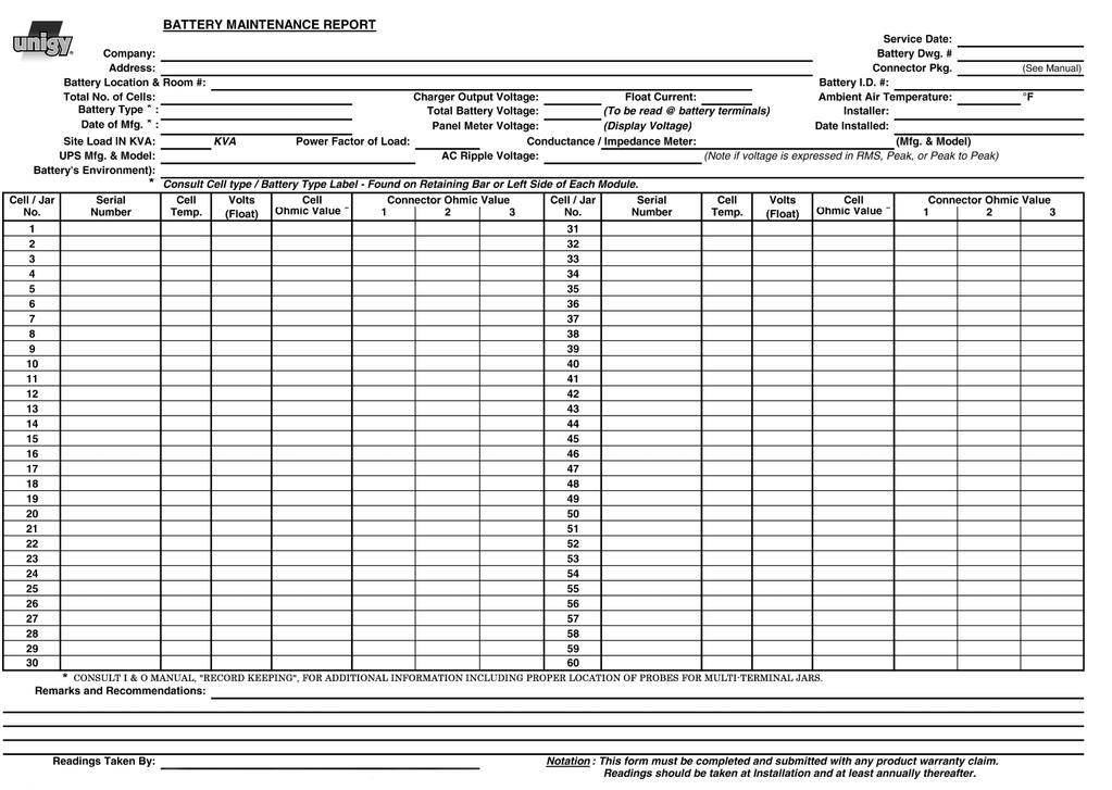
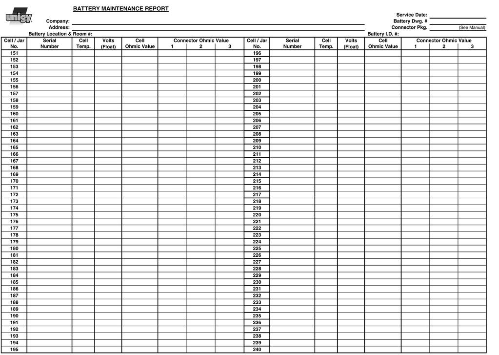
11 Top Protection Shield Installation For side terminal assembly, attach top protective cover to highest front shield. For top terminal assembly, cut protective cover to fit between the terminals and then attach to front shield. Rectifier Ripple Voltage Acceptable charging ripple (peak to peak) shall be less than 0.5% of the manufacturer s recommended string float voltage or have a duration shorter than 8 milliseconds. SYSTEM OPERATIONS Charger Voltage These batteries are designed for continuous float applications. When setting the float voltage on the charger, the system should be set to float at the nominal cell float voltage times the number of cells per string. The charger must be able to maintain the system voltage within ± 0.5% of the desired level at all times. The desired float voltage varies with temperature according to the table below. Operating Temperatures Battery Temperature Float Voltage per cell F C +.01 volts The average battery operating temperature should not exceed 95 F (35 C) and never exceed 105 F (40.5 C) for more than an eight-hour period. Operating at temperatures greater than 77 F (25 C) will reduce the operating life of the battery. If operating temperatures are expected to be in excess of 95 F (35 C), contact East Penn for recommendations. RECORD KEEPING Voltages, Temperatures & Ohmic Readings Record keeping is an important part of stationary battery maintenance and warranty coverage. This information will help in establishing a life history of the battery and inform the user if and when corrective action needs to be taken. (Refer to Battery Maintenance Report). While it is acceptable to operate at temperatures less than 77 F (25 C), it will require longer charging time to become fully recharged. Also, the capacity will be less at operating temperatures below 77 F (25 C). After installation and when the batteries have been on float charge for one week, the following data should be recorded: 1. Battery terminal voltage 2. Charger voltage 3. Individual cell float voltages 4. Ambient temperatures 5. Terminal connections should be checked to verify that the installer did torque all connections properly (125 ± 5 in-lbs). Micro-ohm readings should be taken across every connection. Refer to meter manufacturer s instructions for proper placement of probes. If any reading differs by more than 20% from its initial installation value, re-torque the connection to 125 ± 5 in-lbs. If the reading still remains high, clean contact surfaces according to Step 1 under Connector Assembly. MEASURE POINT MEASURE POINT 6. Individual cell ohmic readings. For 6-post cells, measure from center positive to center negative posts. Do not measure diagonally from positive to negative posts. See below for specific location. MEASURE POINT Cell Voltage Although the charger must maintain the system voltage within ± 0.5%, individual cell voltages may vary by ± 0.05 volts of the average cell float voltage. MEASURE POINT 11
12 MAINTENANCE Always wear eye protection when working on or near batteries. Keep sparks and open flames away from batteries at all times. See Safety Precautions on pg. 3. Annual Inspection (1) 1. Conduct a visual inspection of each cell. 2. Record the battery string voltage. 3. Record the charger voltage. 4. Record the individual cell voltages. The accuracy of the DMM (Digital Multimeter) must be.05% (on dc scale) or better. The DMM must be calibrated to NIST traceable standards. Because float readings are affected by discharges and recharges, these readings must be taken when batteries have been on continuous, uninterrupted float for at least one month. Cells should be within ± 0.05 volts of the average cell float voltage. 5. Record the ambient temperatures. 6. Record individual cell ohmic readings. 7. Record all intercell, interunit, and terminal connection resistances. Micro-ohm readings should be taken during this inspection. If any reading differs by more than 20% from initial readings taken, retorque the connection. Recheck the micro-ohm reading. If the reading remains high, clean the contact surface according to installation portion of this manual. (1) Other Maintenance Inspection intervals follow IEEE 1188 Battery Cleaning 1. Disconnect battery system from power source. 2. Dust accumulation can be removed with cloth dampened with clean water. 3. Corrosion buildup should be neutralized using a mixture of baking soda and water. Use cloth dampened with clean water to remove residue. Capacity Testing Do not discharge the batteries beyond the specified final voltage. When discharging at higher rates, extra connectors may need to be added to prevent excessive voltage drop. When performing capacity testing and recording data use IEEE 1188 instructions. Should it be determined that any individual battery(ies) or cell(s) need to be replaced, contact your nearest East Penn agent or East Penn Service Center. Cell / Sleeve Removal Procedure 1. Before removing cell/sleeve review Safety Precautions on pg. 3 of this manual. Contact East Penn Mfg. Company Inc. with specific questions or concerns. 2. Disconnect battery system from power source. 3. Remove safety shield from subject module. 4. Remove connectors pertaining to cell being removed. 5. Remove 3/8-16 bolts from cell/ sleeve. Do not remove retainer bar from cell/sleeve. 6. All tools used to remove cell/sleeve shall be insulated to avoid contact with battery posts. 7. Lifting device shall be rated to handle weight of cell/sleeve. 8. Remove one cell/sleeve at a time. 9. A slot is provided on the cell/sleeve to assist in removing cell/sleeve from module. 10. Refer to Page 5 Cell Installation for installing replacement cell. AVR4000 Acid Volumes & Weights Cell Electrolyte Pure Size cc gal. gm lb Acid lb AVR **Data subject to change without notice. MSDS Sheets can be obtained at 12
13

14
15
16 DISTRIBUTED BY: Lyon Station, PA Phone: Fax: Order Department Hotline: E.P.M. Form No Rev. 09/ by EPM Printed in U.S.A. All data subject to change without notice. No part of this document may be copied or reproduced, electronically or mechanically, without written permission from the company.
INSTALLATION AND OPERATION MANUAL
 INSTALLATION AND OPERATION MANUAL TABLE OF CONTENTS SAFETY PRECAUTIONS Protective Equipment...3 Procedures...3 RECEIVING & STORAGE Receiving Inspection...3 Unpacking...3 Storage...4 INSTALLATION General...4
FLUSH EYES IMMEDIATELY WITH WATER. GET MEDICAL HELP FAST. SULFURIC ACID CAN CAUSE BLINDNESS OR SEVERE BURNS.
 8A & 8G BATTERY INSTALLATION AND OPERATING INSTRUCTIONS This manual is intended to be a guide to optimize battery performance for multiple cyclic & float applications. Consult applicable User Manuals for
NB Module. Installation and Operation Manual. California Proposition 65 Warning:
 NB Module Installation and Operation Manual California Proposition 65 Warning: Batteries, battery posts, terminals and related accessories contain lead and lead compounds, and other chemicals known to
VRLA Batteries. Battery Installation And Start up Guide
 TECHNICAL MANUAL 41-7525 VRLA Batteries 26-206 Ampere-Hour Capacity Battery Installation And Start up Guide (For Rack Mounted Systems) 41-7525/0514/CD www.cdtechno.com Table of Contents 12V VRLA Battery
Installation and Operating Procedures For C&D Technologies TRUE Front Access TEL Series Batteries
 RS-2046 Installation and Operating Procedures For C&D Technologies TRUE Front Access TEL Series Batteries FOLLOW MANUFACTURER S PUBLISHED INSTRUCTIONS WHEN INSTALLING, CHARGING AND SERVICING BATTERIES.
Dual-Lite Trident TRF 40 Wide Battery Cabinet 20-40kVA Systems USER MANUAL
 Dual-Lite Trident TRF 40 Wide Battery Cabinet 20-40kVA Systems USER MANUAL 755-00020-DL 5/17/2017 2 755-00020-OEM R01 TABLE OF CONTENTS 1. Important Information About This Manual... 4 1.1 Manual Symbols...
AGM Series. Installation Manual AGM Series Modular Battery Systems
 Installation Manual Modular Battery Systems Installation Manual Modular Battery Systems IMPORTANT! Read safety information first See Safety, Storage, Operating and Maintenance Manual The installation
Installation and Operating Procedures For C&D Technologies TRUE Front Access TEL Series Batteries
 RS02046 Installation and Operating Procedures For C&D Technologies TRUE Front Access TEL Series Batteries FOLLOW MANUFACTURER S PUBLISHED INSTRUCTIONS WHEN INSTALLING, CHARGING AND SERVICING BATTERIES.
BR62 Battery Rack Installation, Operation, & Maintenance Manual
 BR62 Battery Rack Installation, Operation, & Maintenance Manual 8/28/2012 2 755-00046 R02 Copyright 2012 C&C Power, Inc. All rights reserved. C&C Power, Inc. 395 Mission Street Carol Stream, IL 60188 www.ccpower.com
Vault Series. Ruggedized, True On Line, Double Conversion Uninterruptible Power Supply USER MANUAL FOR MODELS: 700VA VA
 Vault Series Ruggedized, True On Line, Double Conversion Uninterruptible Power Supply USER MANUAL FOR MODELS: 700VA - 1500VA Safety Instructions...1 1.Introduction...3 2. System Description...3 2.1 General
Valve Regulated Lead Acid Batteries
 Motors I Automation I Energy I Transmission & Distribution I Coatings Batteries - VRLA Valve Regulated Lead Acid Batteries User Manual User Manual Series: Sealed Batteries Language: English Document:
INSTALLATION & OPERATING INSTRUCTIONS
 INSTALLATION & OPERATING INSTRUCTIONS SECTION 92.30 2016-09 INDEX Page Section 1 - GENERAL INFORMATION 1.0 Marathon/Sprinter/SUNlyte Batteries 1 Section 2 - SAFETY PRECAUTIONS 2.0 Safety Alert 1 2.1 Sulfuric
C&D Technologies, Inc. Dynasty Division 900 East Keefe Avenue Milwaukee, WI53212 Phone: Fax:
 , C&D Technologies, Inc. Dynasty Division 900 East Keefe Avenue Milwaukee, WI53212 Phone: 800-396-2789 Fax: 414-961-6506 Form 41-7525 (Rev.6100) Printed in U.S.A. Inter-tier, Inter-Unit Inter-row Cables,
INSTALLATION AND OPERATION INSTRUCTIONS
 INSTALLATION AND OPERATION INSTRUCTIONS Ref No: ARB- MAN-Quanta-13-001 This document details procedures to be followed while installing and operating AMARON QUANTA TM SMF-VRLA batteries. The procedures
INSTALLATION AND OPERATING INSTRUCTIONS FOR FLOODED TUBULAR-HP AND TUBULAR-LM FAST CHARGE MOTIVE POWER BATTERIES
 PLEASE READ THESE INSTRUCTIONS BEFORE PLACING BATTERIES INTO SERVICE. THESE INSTRUCTIONS MUST BE SHIPPED WITH THE BATTERY AND MUST BE DELIVERED TO THE USER. INSTALLATION AND OPERATING INSTRUCTIONS FOR
Basic Battery Safety. Lead Acid Storage Batteries
 Basic Battery Safety Lead Acid Storage Batteries Hazards of Lead Acid Batteries Chemical burns (sulfuric acid) Arc flash / burns Shock Explosive gas (hydrogen) Fire Weight Sulfuric Acid Safety PPE requirements
Installation, Operation & Maintenance Manual DataSafe HX Front Terminal Battery Cabinets
 Installation, Operation & Maintenance Manual DataSafe HX Front Terminal Battery Cabinets Publication No. US-HXFTCAB-IM-001 This manual provides instructions regarding safety, storage, installation, operation
SOS SERIES SOS1 SOS2. Spares On Site Battery Cabinet Installation Guide rEV3
 Atlantic Battery Systems 1065 Market Street Paterson, NJ 07513 Phone: (800) 875-0073 Fax: (973) 523-2344 sales@atbatsys.com www.atbatsys.com SOS1 SOS2 SOS SERIES Spares On Site Battery Cabinet Installation
Deep Cycle Battery Safety. First. Battery Handling, Maintenance & Test Procedures
 Deep Cycle Battery Safety. First. Battery Handling, Maintenance & Test Procedures Crown deep cycle batteries employ a low-maintenance design. They do require periodic maintenance and effective charging
HAZE 6/12 Volt. STATIONARY 6/12 Volt BATTERIES. HAZE Battery Co. INSTALLATION and OPERATING INSTRUCTIONS. Supplied Worldwide by :
 HAZE 6/12 Volt STATIONARY 6/12 Volt BATTERIES INSTALLATION and OPERATING INSTRUCTIONS Supplied Worldwide by : HAZE Battery Co. TABLE OF CONTENTS SECTION CONTENT PAGE SECTION CONTENT PAGE 1.0 GENERAL INFORMATION
INSTALLATION AND OPERATING INSTRUCTIONS FOR FLOODED TUBULAR-HP MOTIVE POWER BATTERIES
 PLEASE READ BEFORE PLACING BATTERIES IN SERVICE THESE INSTRUCTIONS TO BE SHIPPED WITH BATTERY AND TO BE DELIVERED TO USER INSTALLATION AND OPERATING INSTRUCTIONS FOR FLOODED TUBULAR-HP MOTIVE POWER BATTERIES
Model: OBD-L On-Board-Diagnostics II Memory Saver Detector
 Model: OBD-L On-Board-Diagnostics II Memory Saver Detector OWNERS MANUAL IMPORTANT SAFETY INSTRUCTIONS SAVE THESE INSTRUCTIONS This manual will show you how to use your memory saver detector safely and
Motive Power. Network Power. Chargers. Bloc Batteries. Accessories. Service
 The Eternity Technologies range is built using only the highest quality and most efficient production processes at our state-of-the-art manufacturing centre in the UAE. It is this innovation, modern design
2 VOLT STATIONARY BATTERIES INSTALLATION
 2 VOLT STATIONARY BATTERIES INSTALLATION and OPERATION MANUAL TABLE OF CONTENTS SECTION CONTENT PAGE SECTION CONTENT PAGE 1.0 GENERAL INFORMATION 2 5.5 Electrical Connections 4 1.1 Battery Characteristics
IMPORTANT SAFETY INSTRUCTIONS
 1163714 1.5 AMP 12VOLT TRICKLE 1.5 AUTOMATIC AMP AUTOMATIC TRICKLE 1.5 AMP AUTOMATIC 12V12VOLT BATTERY CHARGER IMPORTANT SAFETY INSTRUCTIONS 1. SAVE THESE INSTRUCTIONS This product offers a wide range
- Optional Audio warning when discharge test is complete or tester malfunction.
 INTRODUCTION Congratulations on acquiring your new LT360 battery discharge tester. The LT360 battery discharge tester has been designed to provide the operator with accurate battery discharge testing and
IMPORTANT SAFETY INSTRUCTIONS
 ASSOCIATED Model 6039 Battery Tester Operator's Manual IMPORTANT SAFETY INSTRUCTIONS 1. SAVE THESE INSTRUCTIONS This manual contains important safety and operating instructions for the battery tester you
Motive Power. Network Power. Chargers. Bloc Batteries. Accessories. Service
 The Eternity Technologies range is built using only the highest quality and most efficient production processes at our state-of-the-art manufacturing centre in the UAE. It is this innovation, modern design
MODEL A96 SERIES. 130Vdc Switchmode Utility Rectifier / Battery Charger. Used with LaMarche Power Cage ECN/DATE
 MODEL A96 SERIES 130Vdc Switchmode Utility Rectifier / Battery Charger Used with LaMarche Power Cage CPN112138 ECN/DATE ISSUE DATE: ECN 17010-12/05 106 BRADROCK DRIVE DES PLAINES, IL. 60018-1967 (847)
Today, we re going to talk about battery safety. We ll discuss all the key issues associated with using batteries safely, including battery hazards,
 Today, we re going to talk about battery safety. We ll discuss all the key issues associated with using batteries safely, including battery hazards, battery charging, and battery maintenance. Although
POWER FOR TOMORROW. Motive Power. Network Power. Chargers. Bloc Batteries. Accessories. Service
 POWER FOR TOMORROW TODAY The Eternity Technologies range is built using only the highest quality and most efficient production processes at our state-of-the-art manufacturing centre in the UAE. It is this
IEEE IAS Atlanta Chapter
 Stationary Battery Sizing IEEE IAS Atlanta Chapter Presented by: Lesley Varga, P.E. Quality Standby Services, LLC 1649 Sands Place, SE, Suite C Marietta, GA 30067 (770) 916-1747 lesley@qualitystandbyservices.com
MODEL ELC-12/60-D BATTERY CHARGER
 *32198* NATIONAL RAILWAY SUPPLY Installing, Operating and Service Instructions for the 12/60 Solid State Charger MODEL ELC-12/60-D BATTERY CHARGER PLEASE SAVE THESE IMPORTANT SAFETY AND OPERATING INSTRUCTIONS
C&D TECHNOLOGIES, DYNASTY Division 900 East Keefe Avenue Milwaukee, WI Phone Fax
 C&D TECHNOLOGIES, DYNASTY Division 900 East Keefe Avenue Milwaukee, WI 53212 Phone 414-967 -6500 Fax 414-961-6506 INC Form 41-7525 Rev 08/99 Printed in the USA TABLE OF CONTENTS Page DYNASTY VRLA Battery
Pump Sentry. Models 812 PS & 1612 PS INSTALLATION INSTRUCTIONS
 Pump Sentry Models 812 PS & 1612 PS INSTALLATION INSTRUCTIONS The Pump Sentry is an innovative power station designed to operate your pump during a power outage. When properly installed, it will provide
Powerware Vdc Extended Battery Cabinet User s Guide.
 Powerware 9125 48 Vdc Extended Battery Cabinet User s Guide www.powerware.com FCC Part 15 Class A EMC Statements NOTE This equipment has been tested and found to comply with the limits for a Class A digital
OWNER S MANUAL. Model YUA2AMPCH 2 AMP Dual-Bank Automatic Battery Charger & Maintainer READ ENTIRE MANUAL BEFORE USING THIS PRODUCT
 Model YUA2AMPCH 2 AMP Dual-Bank Automatic Battery Charger & Maintainer Certified by California BCS Regulations OWNER S MANUAL READ ENTIRE MANUAL BEFORE USING THIS PRODUCT READ ENTIRE MANUAL BEFORE USING
MODEL ELC-12/40-CVM-D BATTERY CHARGER
 NATIONAL RAILWAY SUPPLY MODEL ELC-12/40-CVM-D BATTERY CHARGER Installing, Operating and Service Instructions for the ELC-12/40-CVM-D Solid State Charger PLEASE SAVE THESE IMPORTANT SAFETY AND OPERATING
Installation And Operation Instructions
 Installation And Operation Instructions For PS Series Mini-Inverter Power Systems Models: PS-55-LP, PS-110-HP, PS-110-LP, PS-220-HP Surface (-S), Recessed (-R) and Ceiling T-Grid (-T) Mounted Versions
Mitsubishi Electric Power Products, Inc. BC55 Battery Cabinet Installation, Operation, & Maintenance Manual
 Mitsubishi Electric Power Products, Inc. BC55 Battery Cabinet Installation, Operation, & Maintenance Manual Built for Mitsubishi Electric Power Products, Inc. by 5/30/2014 2 755-00041 R08 This manual contains
Monoblock Flooded System. Installation and Operation Manual
 Monoblock Flooded System Installation and Operation Manual TABLE OF CONTENTS Safety Precautions Protective Equipment...1 Procedures...1 Hazardous Elements...1 First Aid for Acid Splash...2 Battery Location
Installation And Operation Instructions
 Installation And Operation Instructions For MPS Series Micro-Inverter Power Sytems Lead Calcium Battery Models: MPS-32 and MPS-55 Nickel Cadmium Battery Models: MPS-20 and MPS-35 Surface (-S), Recessed
EnergyCell FLA Series. Owner s Manual
 Series Owner s Manual About OutBack Power Technologies OutBack Power Technologies is a leader in advanced energy conversion technology. OutBack products include true sine wave inverter/chargers, maximum
MODEL A97 SERIES. Switchmode Utility Rectifier/Battery Charger ECN/DATE
 MODEL A97 SERIES Switchmode Utility Rectifier/Battery Charger CPN108172 ISSUE DATE: 16071 7/03 ECN/DATE 106 BRADROCK DRIVE DES PLAINES, IL. 60018-1967 (847) 299-1188 FAX: (847)299-3061 Page 1 of 7 INSTRUCTION
INSTALLATION & OPERATING INSTRUCTIONS
 INSTALLATION & OPERATING INSTRUCTIONS SECTION 93.10 2014-08 YOUR GNB REPRESENTATIVE SAlESPErSoN TElEPhoNE location GNB SERVICE ASSISTANCE 1-800-241-4895 INDEX Page SECTION 1 1.0 General Information....................1
Installation And Operation Instructions
 Installation And Operation Instructions For LPS Series Micro Inverter Power Systems Lead Calcium Battery Models: LPS32 and LPS55 Nickel Cadmium Battery Models: LPS20 and LPS35 Surface (-S), Recessed (-R)
ALTERNATOR REQUESTED INFORMATION. Vehicles With Dual Generator [ Engine Mount - LH ] 2007 Ford Pickup 6.0L Eng F350 Super Duty
![ALTERNATOR REQUESTED INFORMATION. Vehicles With Dual Generator [ Engine Mount - LH ] 2007 Ford Pickup 6.0L Eng F350 Super Duty](/thumbs/72/66590437.jpg "ALTERNATOR REQUESTED INFORMATION. Vehicles With Dual Generator [ Engine Mount - LH ] 2007 Ford Pickup 6.0L Eng F350 Super Duty") ALTERNATOR 2007 Ford Pickup 6.0L Eng F350 Super Duty REQUESTED INFORMATION Vehicles With Dual Generator [ Engine Mount - LH ] Fig 1: Rotating Drive Belt Tensioner Clockwise 1. Remove the accessory drive
ALTERNATOR 2007 Ford Pickup 6.0L Eng F350 Super Duty REQUESTED INFORMATION Vehicles With Dual Generator [ Engine Mount - LH ] Fig 1: Rotating Drive Belt Tensioner Clockwise 1. Remove the accessory drive
INSTRUCTION MANUAL FOR PC63 CAGE
 INSTRUCTION MANUAL FOR PC63 CAGE CPN106833 ISSUE DATE: 15689-12/02 ECN/DATE 106 BRADROCK DRIVE DES PLAINES, IL. 60018 (847) 299-1188 FAX: (847) 299-3061 16816-6/05 INSTRUCTION DRAWING NUMBER: P25-LPC63-1
FIAMM Industrial Batteries December 2012 FIAMM AGM Valve Regulated Recombination Batteries: FLX Series- Engineering Manual TABLE OF CONTENTS
 TABLE OF CONTENTS PAGE 1 OPERATING CHARACTERISTICS 2 2 INSTALLATION 4 3 CHARGING 6 4 STORAGE AND REFRESH CHARGING 8 5 MAINTENANCE AND TESTING 9 6 SAFETY 10 7 APPLICABLE STANDARDS 10 8 RECORDS DATA 10 FIAMM.
SENS DC PowerCab 120 Installation, Operation, & Maintenance Manual
 Installation, Operation, & Maintenance Manual Stored Energy Systems Packaged By: 1840 Industrial Circle C&C Power, Inc. Longmont, Co 80501 395 Mission Street www.sens-usa.com Carol Stream, IL 60188 Technical
AUTOMATIC BEST BATTERY SELECTOR INSTALLATION & OPERATION BBS-1600 BBS-1600E
 AUTOMATIC BEST BATTERY SELECTOR INSTALLATION & OPERATION BBS-1600 BBS-1600E SENS part no: 101314 Document revision: H DCN No. 107395 Date 11/22/17 1840 Industrial Circle Longmont, CO 80501 Fax: (303) 678-7504
TOBi PI Wi-Z. Performance Indicator and Event Logger. Quick Installation Guide
 TOBi PI WiZ Performance Indicator and Event Logger Quick Installation Guide S470180 Revised 6/19/2015 Safety Instructions WARNING BATTERIES CONTAIN LETHAL VOLTAGE LEVELS. INSTALLATION AND SERVICING MUST
INSTRUCTION MANUAL. Maintenance-free Absorbent Glass Mat technology and valve-regulated batteries. (AGM / VRLA)
") INSTRUCTION MANUAL Maintenance-free Absorbent Glass Mat technology and valve-regulated batteries. (AGM / VRLA) DESCRIPTION / TYPE: SUN BATTERY Nominal values Nominal voltage UN: 2V Cells 6V Blocks 12V
INSTRUCTION MANUAL Maintenance-free Absorbent Glass Mat technology and valve-regulated batteries. (AGM / VRLA) DESCRIPTION / TYPE: SUN BATTERY Nominal values Nominal voltage UN: 2V Cells 6V Blocks 12V
10 AMP ON BOARD BATTERY CHARGER
 R A Valley Forge Company MODEL 2611A-1-B 10 AMP ON BOARD BATTERY CHARGER One Output OWNER S MANUAL IMPORTANT! READ THESE INSTRUCTIONS BEFORE INSTALLING AND USING THIS PRODUCT. Keep these instructions for
AUTOMATIC BEST BATTERY SELECTOR INSTALLATION & OPERATION BBS-4800 BBS-4800E
 AUTOMATIC BEST BATTERY SELECTOR INSTALLATION & OPERATION BBS-4800 BBS-4800E SENS part no: 101312 Document revision: K DCN No. 107455 Date 4/2/18 1840 Industrial Circle Longmont, CO 80501 Fax: (303) 678-7504
A48 / A48B (base plate) BATTERY CHARGER
 BATTERY CHARGER") A48 / A48B (base plate) BATTERY CHARGER CPN41054 ISSUE DATE: 12315-8/98 ECN/DATE 106 BRADROCK DRIVE DES PLAINES, IL. 60018-1967 (847) 299-1188 FAX: (847)299-3061 15349-07-07/02 16041 6/03 14575-2/01 INSTRUCTION
A48 / A48B (base plate) BATTERY CHARGER CPN41054 ISSUE DATE: 12315-8/98 ECN/DATE 106 BRADROCK DRIVE DES PLAINES, IL. 60018-1967 (847) 299-1188 FAX: (847)299-3061 15349-07-07/02 16041 6/03 14575-2/01 INSTRUCTION
6/12 VOLT STATIONARY BATTERIES INSTALLATION and OPERATION MANUAL
 /1 VOLT STATIONARY BATTERIES INSTALLATION and OPERATION MANUAL TABLE OF CONTENTS SECTION CONTENT PAGE SECTION CONTENT PAGE 1.0 1.1.0.1..3. 3.0 3.1 3..0.1. GENERAL INFORMATION Battery Characteristics SAFETY
INSTALLATION & OPERATING INSTRUCTIONS
 INSTALLATION & OPERATING INSTRUCTIONS SECTION 93.10 2016-07 A Division of Exide Technologies YOUR GNB REPRESENTATIVE SALESPERSON TELEPHONE LOCATION GNB SERVICE ASSISTANCE 1-800-241-4895 INDEX Page SECTION
AUTO CHARGE 11 MODEL #: XX. AUTOMATIC BATTERY CHARGER U.L. Configuration INSTRUCTION MANUAL
 INSTRUCTION MANUAL AUTO CHARGE 11 AUTOMATIC BATTERY CHARGER U.L. Configuration MODEL #: 091-11-XX NOTE : This charger is designed for vehicles with dual batteries and negative ground. CAUTION This unit
AlphaCell OPzS. Technical Manual. Stationary Flooded Tubular Lead-acid Batteries. AlphaCell OPzS Battery. Effective: January Alpha Technologies
 AlphaCell OPzS Stationary Flooded Tubular Lead-acid Batteries Technical Manual AlphaCell OPzS Battery Effective: January 2008 Alpha Technologies Power Alpha Technologies AlphaCell OPzS Battery Installation
Jumpbox Model SP-12V1500-JB1
 FLEET PRO 1500D Jumpbox Model SP-12V1500-JB1 Questions, missing parts, problems? Before returning to your retailer, send us a message through our Contact Us page on Starkpower.com ONE YEAR LIMITED WARRANTY
INSTALLATION, OPERATING & MAINTENANCE INSTRUCTIONS For Valve Regulated Lead Acid Batteries used in Stationary Applications
 INSTALLATION, OPERATING & MAINTENANCE INSTRUCTIONS For Valve Regulated Lead Acid Batteries used in Stationary Applications Commissioning by:... Date:... Number of cells/blocks:... Model #:... SAFETY PRECAUTIONS
Installation and Operating Instructions for Monolite. Valve-Regulated Lead Acid Batteries
 Installation and Operating Instructions for Monolite Valve-Regulated Lead Acid Batteries Important Note Monolite batteries must be placed on charge within 6 months from date of shipment. Failure to observe
BATTERY & STARTER ANALYSER (BSA-12) User Manual
 User Manual") BATTERY & STARTER ANALYSER (BSA-12) User Manual Introduction BSA-12 Battery Starter Analyser does not carry internal batteries but is powered up from external DC source ranging from 9V to 15V DC. It is
BATTERY & STARTER ANALYSER (BSA-12) User Manual Introduction BSA-12 Battery Starter Analyser does not carry internal batteries but is powered up from external DC source ranging from 9V to 15V DC. It is
PORTABLE TRASH PUMPS MDP200
 PORTABLE TRASH PUMPS MDP200 OPERATING & PARTS MANUAL INTRODUCTION This manual provides information and procedures to safely operate and maintain the engine and pump. For your own safety and protection
Installation and Operation Instructions SERVICE BY QUALIFIED PERSONNEL ONLY
 ELI-S-600 120 Volt ELI SERIES EMERGENCY LIGHTING INVERTERS Installation and Operation Instructions! IMPORTANT SAFEGUARDS! WHEN USING ELECTRICAL EQUIPMENT, BASIC SAFETY PRECAUTIONS SHOULD ALWAYS BE FOLLOWED,
Automatic Battery Charger Switching mode with Micro-controlled Input: Vac / Output: 12Volt DC
 Automatic Battery Charger Switching mode with Micro-controlled Input:220-260Vac / Output: 12Volt DC User s Manual and Important Safety Information Model: OC-SW121080 / OC-SW121160 / OC-SW121210 FEATURES
12V Manual Battery Charger
 OPERATOR S MANUAL 12V Manual Battery Charger Model No. 28.71221 Read and follow all Safety Rules and Operating Instructions before Every Use of this Product. SAVE THESE INSTRUCTIONS. Sears Brands Management
Smart Charger 12-24V 60A, 1600W
 Smart Charger 12-24V 60A, 1600W Installation and User Manual Advanced Battery Chargers Table of contents Important SC 60A General SC60A 2 General 2 Installation 3 Operations 4 Safety Instructions 5 Troubleshooting
TECHNICAL MANUAL RS02061
 TECHNICAL MANUAL RS02061 Standby Batteries for Renewable Energy Applications Installation and Operating Instructions RS02061/0514/CD www.cdtechno.com Table of Contents Table of Contents 2 SAFETY PRECAUTIONS
SAVE THESE INSTRUCTIONS
 R MODEL 2611 10 AMP ON BOARD BATTERY CHARGER Two Outputs OWNER S MANUAL Connections at a glance: For the best charging results both 12 Volt independent batteries should be equally discharged. The charger
Automatic Battery Charger Switching mode with Micro-controlled Input: Vac / Output: 12Volt DC
 Automatic Battery Charger Switching mode with Micro-controlled Input:220-260Vac / Output: 12Volt DC User s Manual and Important Safety Information Model: OC-SW121080 / OC-SW121160 / OC-SW121210 FEATURES
BC-9000 OPERATIONS MANUAL BATTERY CHARGER COFKO ELECTRONICS LLC COPYRIGHT 2014 P/N
 BC-9000 BATTERY CHARGER OPERATIONS MANUAL COFKO ELECTRONICS LLC COPYRIGHT 2014 P/N 4169-20 UNPACKING As you unpack your new BC-9000 battery charger, inspect the BC-9000 for signs of shipping damage. If
JOHN DEERE WORLDWIDE COMMERCIAL & CONSUMER EQUIPMENT DIVISION. Lawn Tractors L100, L110, L120, and L130 TM2026 DECEMBER 2002 TECHNICAL MANUAL
 2026 December 2002 JOHN DEERE WORLDWIDE COMMERCIAL & CONSUMER EQUIPMENT DIVISION Lawn Tractors L100, L110, L120, and L130 TM2026 DECEMBER 2002 TECHNICAL MANUAL North American Version Litho in U.S.A. Safety
LMI Watt Models
 LMI 300-600 Watt Models Service Questions Call: 800-451-9423 INSTALLATION AND OPERATING INSTRUCTIONS IMPORTANT SAFEGUARDS When using electrical equipment, basic safety precautions should always be followed,
NILFISK BA 500 Service Manual
 NILFISK BA 500 Service Manual Model 66324400 12/94 Form Number 043023 TABLE OF CONTENTS Batteries...21 Brush Drive Belt Adjustment Or Replacement...7 Brush Drive Motor - Carbon brush Inspection... 8 Brush
Single-Point Watering Kit User s Guide
 Single-Point Watering Kit User s Guide Contents 01 Kit Contents...................................3 02 Safety Instructions and Warnings.........................4 03 General Information and Precautions.......................
User Guide IGD Series
 US User Guide IGD Series DANGER PRIOR TO USE, READ AND UNDERSTAND PRODUCT SAFETY INFORMATION. Failure to follow the instructions may result in ELECTRICAL SHOCK, EXPLOSION, or FIRE, which may result in
A+ Battery Backup Power Supply For use with Hydromatic model B-A1/BV-A1
 Unit Installation and Service Manual A+ Battery Backup Power Supply For use with Hydromatic model B-A1/BV-A1 NOTE! To the installer: Please make sure you provide this manual to the owner of the pumping
PSJ-2212, PSJ-3612, PSJ-4424
 Model: PSJ-2212, PSJ-3612, PSJ-4424 Jump Starter and DC Power Source OWNER S MANUAL PSJ-2212 PLEASE SAVE THIS OWNER S MANUAL AND READ BEFORE EACH USE. This manual will explain how to use your jump starter
PAC 600 PAC 800 PAC 800 comfort
 PAC 600 PAC 800 PAC 800 comfort Installation and User Manual Advanced Battery Chargers Table of contents POWERFINN PAC 600/800...2 General... 2 Installation...3 Operations... 4 Safety Instructions... 5
OBAE, OBAEXU, ON BOARD Battery Chargers
 C O R P O R A T IO N O P E R A T I N G I N S T R U C T I O N S OBAE, OBAEXU, ON BOARD Battery Chargers INTRODUCTION: The OBAE line of chargers are designed for the permanent installation on battery powered
Installation and Operation Manual Nickel Iron MG300 Battery
 Installation and Operation Manual Nickel Iron MG300 Battery Effective: July 2015 Nickel Iron MG300 Battery MG300 Encell Technology, Inc. Effective Date: July 2015 Encell Technology, Inc. NOTE: Photographs
Cruising Charger Series OWNER S MANUAL
 R Cruising Charger Series OWNER S MANUAL ON BOARD BATTERY CHARGERS Models DC Amperage No. Of Banks Volts 2614A 5,10 Amps 2 Bank 12/12 2614A-230 2621A 5,5,10 Amps 3 Banks 12/12/12 2621A-230 2622A 10,10
PORTABLE TRASH PUMPS MTP200 MTP300 MTP400
 PORTABLE TRASH PUMPS MTP200 MTP300 MTP400 OPERATING & PARTS MANUAL INTRODUCTION This manual provides information and procedures to safely operate and maintain the engine and pump. For your own safety and
AT125-B ASSEMBLY INSTRUCTIONS
 POWERSPORTS AT125-B ASSEMBLY INSTRUCTIONS 031218 PLEASE NOTE THAT THIS IS NOT THE OWNER S MANUAL BUT THE ASSEMBLY INSTRUCTIONS ONLY. BEFORE OPERATING THIS ATV, MAKE SURE THE OPERATOR HAS READ AND UNDERSTANDS
INSTRUCTION MANUAL. 12-Station HD Shop 12V Portable Battery Charger
 INSTRUCTION MANUAL 12-Station HD Shop 12V Portable Battery Charger IMPORTANT SAFETY INSTRUCTIONS 1. SAVE THESE INSTRUCTIONS This manual contains important safety and operating instructions for your HD
20W Polycrystalline Solar Panel
 20W Polycrystalline Solar Panel User Manual WARNING: ead and understand all instructions, warnings, and cautions before using this product. Failure to follow the instructions, warnings, and cautions ay
INSTRUCTIONS FOR CONTINUED AIRWORTHINESS COMPONENT MAINTENANCE MANUAL CONCORDE VALVE REGULATED LEAD-ACID RG-441 BATTERY AUTHORISED UNDER TSO-C173
 INSTRUCTIONS FOR CONTINUED AIRWORTHINESS COMPONENT MAINTENANCE MANUAL CONCORDE VALVE REGULATED LEAD-ACID RG-441 BATTERY AUTHORISED UNDER TSO-C173 The data/information contained herein has been reviewed
Safety, Storage, Installation, Operation & Maintenance Manual. Flooded Lead-Acid Batteries C, D, E, F and G
 Safety, Storage, Installation, Operation & Maintenance Manual Flooded Lead-Acid Batteries C, D, E, F and G This manual provides instructions regarding safety, storage, installation, operation and maintenance.
AUTO CHARGE 12 HO MODEL #: MODEL #: MODEL #: AUTOMATIC SINGLE OUTPUT BATTERY CHARGER INSTRUCTION MANUAL
 INSTRUCTION MANUAL AUTO CHARGE 12 HO AUTOMATIC SINGLE OUTPUT BATTERY CHARGER MODEL #: 091-170-6 MODEL #: 091-170-12 MODEL #: 091-170-24 File: IM_091-170-xx_revd.indd Rev: D Revised By: MFG Date: 10-23-2013
Installation, Operation & Maintenance Manual
 Installation, Operation & Maintenance Manual Picture may differ from your specific application For Pro-Fill kits with part numbers beginning in BG BL-175 9-20-13 General Information & Precautions This
RoaDCharger 20 Amp 7 Way Installation Manual
 RoaDCharger 20 Amp 7 Way Installation Manual Safety First This symbol is used to call attention to instructions concerning personal safety. Be sure to observe and follow these instructions. Take time to
LIBERTY SERIES 1000 VALVE REGULATED LEAD-CALCIUM BATTERY For standby applications Capacities from 25 to 600 Ampere-hours
 RETURN RECYCLE 12-373 LEAD LIBERTY SERIES 1000 VALVE REGULATED LEAD-CALCIUM BATTERY For standby applications Capacities from 25 to 600 Ampere-hours UL Recognized Component C&D Technologies Powercom Division
Model: SE-4020-CA Automatic Battery Charger
 OWNERS MANUAL Model: SE-4020-CA Automatic Battery Charger PLEASE SAVE THIS OWNERS MANUAL AND READ BEFORE EACH USE. This manual will explain how to use the battery charger safely and effectively. Please
Installation Instructions and User Manual For. 100 Watt Inverter Power System
 Installation Instructions and User Manual For 100 Watt Inverter Power System Installation Instructions and User Manual For LiteGear 100 Watt Inverter Power System Warning: THIS PRODUCT CONTAINS CHEMICALS
CRS1, CRS2 and CRS3. For additional information please call our. PRO CHARGING SYSTEMS, LLC 1551 Heil Quaker Boulevard, LaVergne, TN
 CRS1, CRS2 and CRS3 For additional information please call our Technical Support Group 800.742.2740 PRO CHARGING SYSTEMS, LLC 1551 Heil Quaker Boulevard, LaVergne, TN 37086-3539 110310 Installation and
OBE, OBEXU, ON BOARD Battery Chargers
 C O R P O R A T IO N O P E R A T I N G I N S T R U C T I O N S OBE, OBEXU, ON BOARD Battery Chargers INTRODUCTION: These chargers are designed for the permanent installation on battery powered vehicles
2/10/50 AMP 12 VOLT BATTERY CHARGER/ ENGINE STARTER
 2/10/50 AMP 12 VOLT BATTERY CHARGER/ ENGINE STARTER WARNING This product contains or, when used, produces a chemical known to the State of California to cause cancer and birth defects or other reproductive
Sentry Battery Charger. Installation and Operations Manual Section 75
 Sentry Battery Charger Installation and Operations Manual 00-02-0616 03-03-08 Section 75 In order to consistently bring you the highest quality, full featured products, we reserve the right to change our