PinPoint Gyro Evaluation Boards
|
|
|
- Eleanor Walsh
- 5 years ago
- Views:
Transcription


1 PinPoint Gyro Evaluation Boards
2 PinPoint Gyro Evaluation Boards Three PinPoint gyro evaluation boards are available: Single-axis CRM100 Gyro Evaluation Board (Part Number ) Single-axis CRM200 Gyro Evaluation Board (Part Number ) Three-axis CRM100/200 Gyro Evaluation Board (Part Number )
3 Statement of Use and Disclaimer Statement of Use and Disclaimer For Silicon Sensing Systems Evaluation Boards The Evaluation Boards described in this document are development tools and as such are provided solely for the evaluation and assessment by the Purchaser of the suitability of the Silicon Sensing Systems Limited (SSSL) range of Inertial Sensors within the Purchaser s application. They are not to be used either as an integral or discrete part or component within any Purchaser application or product. SSSL does not warrant the specification or performance of these boards in anyway whatsoever in such circumstances where use by the Purchaser for any application or product is in contravention of the foregoing advice from SSSL. The Purchaser uses these Evaluation Boards entirely at its own risk and shall fully indemnify SSSL from any and all Purchaser or third party claims, losses, costs, damages and expenses and related liability whether in contract or tort that may arise from such improper use as provided in this statement. This statement is supplementary to SSSL Standard Terms and Conditions. In the event of any conflict this Statement shall prevail and all other terms shall remain valid and enforceable.
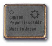
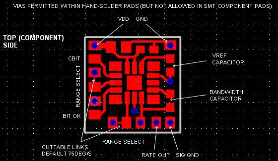
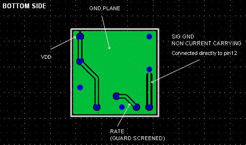
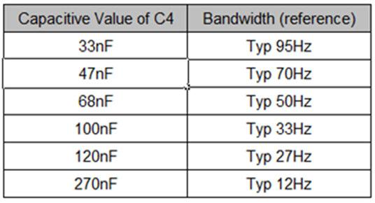
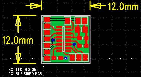
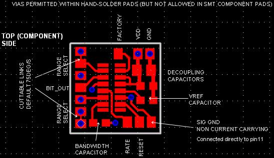
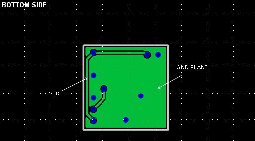
4 Single-Axis PinPoint Evaluation Boards Single-Axis CRM100 and CRM200 PinPoint Gyro Evaluation Boards: Two Part Numbers Available: (CRM100) & (CRM200) Board Size: 12mm x 12mm Board Mounting: No mounting holes (anticipate gluing/taping onto customer s host system). PCB material: 1.6mm FR4, solder resist. Power Supply: +3V and 0V (2 SMT solder pads). Analogue outputs: 1 channel + 1 signal ground (2 SMT solder pads in total). Digital interface: Not available. Rate range: 75, 150, 300, or 900 deg/sec. 75deg/sec default as supplied. Other rate ranges can be selected by cut-able copper tracks see Schematic Drawing. Rate range selection: Solder wire links. 4 SMT pads in total. See Schematic Drawing. Bandwidth capacitor: An 0805 SMT footprint to accommodate values of between 560pF and 33nF. Default as supplied 60Hz (47nF) Other components: Decoupling 0.1µF, 10µF. Vref_cap 0.1µF. Total number of customer usable SMT solder pads: 12 mounted on component side.

5 Single-Axis CRM100 - Schematic CBIT BIT_OUT SEL1 SEL0 CBIT BIT_OUT SEL1 SEL0

6 Single-Axis CRM100 Pad locations
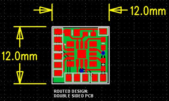
7 Single-Axis CRM100 - Layout


8 Single-Axis CRM200 - Schematic

9 Single-Axis CRM200 Pad locations
10 Single-Axis CRM200 - Layout
11 3-Axis PinPoint Evaluation Board 3-Axis CRM100/200 PinPoint Gyro Evaluation Board Part Number: Board Size: 25mm x 25mm Board Mounting: Four screw mounting holes. PCB material: 1.6mm FR4, solder resist. Devices used: 1 piece CRM100 (e.g. yaw), 2 pieces CRM200 (e.g. roll and pitch). Power Supply: +3V and 0V (2 SMT solder pads). Analogue outputs: 3 independent channels (one for each axis) + 1 (non-current carrying) signal ground? (4 SMT solder pads in total). Digital interface: 3 independent SPI buses (one for each axis), each comprising of CLK, MISO, MOSI, /EN (12 SMT solder pads in total). Rate range: 75, 150, 300, or 900 deg/sec for each axis. 75deg/sec default as supplied. Other ranges selected by cut-able copper tracks. See Layout Drawing. Rate range selection: Solder wire links. 3 independent channels (one for each axis), each comprising of 4 pads (12 SMT pads in total). See Layout Drawing. Bandwidth capacitor: 3 independent channels (one for each axis) each comprising of an 0805 SMT footprint (3 in total) to accommodate values of between 560pF and 33nF. Other components: Decoupling 0.1µF, 10µF. Vref_cap 0.1µF. Total number of customer usable SMT solder pads: 30 mounted on component side.
12 3-Axis - Schematic For rate range and bandwidth adjustment, see next slide

 A6 A8 A10 A12 A7 A9 A11 A13 150 /s A6 A8 A10 A12 A7 A9 A11 A13 300 /s A6 A8 A10 A12 A7 A9 A11")
13 3-Axis Pad locations and links Rate range is set individually for each axis. Replace An below by Rn, Pn, Yn for the Roll, Pitch and Yaw axes Bandwidth is set individually for each axis. The capacitors R_C3, P_C3, Y_C3 should be fitted in accordance with the table below 75 /s (default) A6 A8 A10 A12 A7 A9 A11 A /s A6 A8 A10 A12 A7 A9 A11 A /s A6 A8 A10 A12 A7 A9 A11 A /s A6 A8 A10 A7 A9 A11 A12 A13

")


14 3-Axis - Layout 25mm SQ Default Links 3V 0V Power Input General View Top Layer (Component Side) Inner Layer 2 (Tracked Grounds, Screen Ground Plane) Vdd Star Point Gnd Star Point Gnd Star Point Gnd Star Point Inner Layer 3 (Tracked Vdd, Screen Ground Plane) Inner Layer 4 (Non-current Carrying Screen Plane) Component Indent Location
15 Contact Details Silicon Sensing Systems Ltd Clittaford Road Southway Plymouth Devon United Kingdom PL6 6DE Tel: Fax : sales@siliconsensing.com Web :
AG903-07E TDFN Current Sensor Evaluation Board
 AG903-07E TDFN Current Sensor Evaluation Board 1A Max TDFN Current Sensor Evaluation Board www.nve.com 800-GMR-7141 Under PCB Through Leadframe Under Sensor 5 Turns AG903-06 SB-00-069B NVE Corporation
MHz Filter
 Applications Broadband tuners DOCSIS 3.0 gateways DOCSIS 3.0 cable modems SMP12D 3.00 x 3.00 x 1.22 mm Product Features Usable bandwidth 100 MHz High attenuation Balanced operation Small Size: 3.00 x 3.00
ZSPM401x Application Note - Circuit Layout and Component Selection Contents
 ZSPM401x Application Note - Circuit Layout and Component Selection Contents 1 Introduction... 2 2 Typical Application Schematic... 2 3 Printed Circuit Board (PCB) Layout Guidelines... 3 4 Recommended Bill
Plessey PS25502PAD EPIC 6-sensor Seat Pad. Instruction Manual
 Plessey PS25502PAD EPIC 6-sensor Seat Pad. Instruction Manual Standard Components PS25502PAD 1 x PS25502PAD seat pad. 1 x Detachable automotive grade leather cover 1 x Detachable cotton cover Figure 1
UM0672 User manual. CRX14 and CR14 reference design PCB Gerber files. Introduction
 User manual CRX14 and CR14 reference design PCB Gerber files Introduction The purpose of this user manual is to give printed-circuit board references to ease design in the case of STMicroelectronics CRX14
Maxim Integrated Products 1
 19-5287; Rev 0; 5/10 MAX9636 Evaluation Kit General Description The MAX9636 evaluation kit (EV kit) is an assembled and tested PCB used to evaluate the MAX9636 lowpower, low-noise, CMOS input op amp, which
UM UBA2024T SO14 13 W demo board. Document information
 Rev. 3 25 January 20 User manual Document information Info Keywords Abstract Content UBA2024T, half-bridge CFL driver, non-dimmable This document describes the correct use of the UBA2024T half-bridge CFL
Application Note TES 1 Series
 1W, Miniature SMD, Single & Dual Output DC/DC Converters Features SMD Package with Industry Standard Pinout Small Footprint: 11.0 x 13.7 mm (0.43 x 0.54 ) Single Output Models 11.0 x 16.3 mm (0.43 x 0.64
Manufacturing Facility is ISO9001:2000. Welded Steel Pipe Conform to ASTM A53. Threads Conform to ASME B1.20.1
 STEEL NIPPLES S40 & S80 Steel Nipple Product Specifications Manufacturing Facility is ISO9001:2000 Welded Steel Pipe Conform to ASTM A53 Threads Conform to ASME B1.20.1 800-678-2544 800-678-0857 www.msi-products.com
CubeSat Kit Linear EPS Hardware Revision: D
 http://www.cubesatkit.com/ TM CubeSat Kit Linear EPS Hardware Revision: D Rechargeable Electrical Power System for CubeSat Kit Bus Applications CubeSat Kit demonstrations CubeSat Kit terrestrial testing
MiT. MOVING image TECHNOLOGIES INSTRUCTIONS FOR INSTALLATION, OPERATION, AND MAINTENANCE. XL Mover / XLW Mover. Manual Version 1.0
 MiT MOVING image TECHNOLOGIES INSTRUCTIONS FOR INSTALLATION, OPERATION, AND MAINTENANCE OF XL Mover / XLW Mover Manual Version 1.0 MOVING image TECHNOLOGIES, LLC. 17760 Newhope St. Fountain Valley, CA
USER MANUAL. Revision 1.0.1
 9ABCDEF08 NMEA2000 EXHAUST MULTIFUNCTION GAS TEMPERATURE DISPLAY Part MODULE Numbers: & PROBE3345 USER Part Numbers: MANUAL 4510 USER MANUAL 1234567 Revision 1.0.1 Revision History 1 1 Introduction 3
LM5576 Evaluation Board
 LM5576 Evaluation Board Introduction The LM5576 evaluation board is designed to provide the design engineer with a fully functional power converter based on Emulated Current Mode Control to evaluate the
MACP TB. 23 db Coupler MHz Rev. V1. Features. Functional Schematic. Description. Pin Configuration 4. Ordering Information 1,2
 23 Coupler Features 23 Coupling Ratio Surface Mount Package Available on Tape and Reel Excellent Temperature Stability RoHS Compliant and Pb Free 260 C Reflow Compatible Description The MACP-0145 is a
Motor Driver PCB Layout Guidelines. Application Note
 AN124 Motor Driver PCB Layout Guidelines Motor Driver PCB Layout Guidelines Application Note Prepared by Pete Millett August 2017 ABSTRACT Motor driver ICs are able to deliver large amounts of current
City Title. . Is System Owner interested in being contacted about energy efficiency opportunities at this site? Title. City. Site Contact.
 To be completed by Solar Electric Design Ally and Project Owner Don't Forget to Include Project Owner and Design Ally Signatures Site Layout Sun Chart Wiring Schematic Program Use Only FastTrack ID Project
ORDERING INFORMATION # of Ports Pressure Type Device Device Name Options
 Freescale Semiconductor Integrated Silicon Pressure Sensor + for Manifold Absolute Pressure, Applications, On-Chip Signal Conditioned, Temperature Compensated and Calibrated The Freescale series Manifold
LANC245.1W12. DC/DC Converter VDC Input 5.1 VDC Output at 2.4A. Features:
 DC/DC Converter 18-36 VDC Input 5.1 VDC Output at 2.4A Features: Applications: Distributed Power Architectures Communications Equipment Computer Equipment Work Stations UL TUV CB CE MARK RoHS Compliant
MAX3747/MAX3747A Evaluation Kit
 19-3297; Rev A; 05/04 MAX3747/MAX3747A Evaluation Kit General Description The MAX3747/3747A evaluation kit (EV kit) simplifies evaluation of the MAX3747/3747A limiting amplifiers. The EV kit enables testing
MicroMate (MMCX) Amphenol Specifications
 Amphenol Specifications") Specifications ELECTRICAL CECC22000 Test Requirement Impedance 50 Ohm Frequency Range DC thru 6 GHz VSWR 4.4.1 SMT and Edgecard (Mated Pair) DC - 4 GHz 1.15 Max 4-6 GHz 1.40 Max Cabled Straight, Semi-Rigid
Specifications ELECTRICAL CECC22000 Test Requirement Impedance 50 Ohm Frequency Range DC thru 6 GHz VSWR 4.4.1 SMT and Edgecard (Mated Pair) DC - 4 GHz 1.15 Max 4-6 GHz 1.40 Max Cabled Straight, Semi-Rigid
MB86R01 Jade PCB Design Guide
 Application Note MB86R01 Jade PCB Design Guide Fujitsu Microelectronics Europe GmbH History Date Author Version Comment 23.02.2007 AvT 1.0 Draft version 25.05.2010 AvT 2.0 Updated using Japanese Guide
V-Twin Forward Control Installation Instructions
 V-Twin Forward Control Installation Instructions Thank you for a choosing a Supreme Legends USA product. Supreme Legends forward controls are designed to add style and performance to your bike. Our extended
Silvertel. Ag9912M Ultra Miniature PoE Module. 1. Features. 2. Description. Tiny SMT package (14mm x 21mm) IEEE802.3af compliant.
 IEEE802.3af compliant.") Silvertel V1.1 September 2016 Datasheet Ultra Miniature PoE Module Pb 1. Features Tiny SMT package (14mm x 21mm) IEEE802.3af compliant Low cost Input voltage range 36V to 57V Minimal external components
Silvertel V1.1 September 2016 Datasheet Ultra Miniature PoE Module Pb 1. Features Tiny SMT package (14mm x 21mm) IEEE802.3af compliant Low cost Input voltage range 36V to 57V Minimal external components
Silver T E L E C O M. 1. Features. 2. Description. IEEE802.3af compliant. Small SIL package size - 56mm (L) x 14mm (H) Low output ripple and noise
 x 14mm (H) Low output ripple and noise") Silver T E L E C O M V2.0 Aug 2008 Pb. Features IEEE802.3af compliant Small SIL package size - 56mm (L) x 4mm (H) Low output ripple and noise Input voltage range 36V to 57V Only one low cost external decoupling
Silver T E L E C O M V2.0 Aug 2008 Pb. Features IEEE802.3af compliant Small SIL package size - 56mm (L) x 4mm (H) Low output ripple and noise Input voltage range 36V to 57V Only one low cost external decoupling
Purpose. Table of Contents. Purpose Introduction General Product Information Key Performance Summary Table... 3
 Purpose The RT7251B is a high-efficiency current mode synchronous step-down regulator that can deliver up to 1.5A output current from a wide input voltage range of 4V to 17V. This document explains the
Silvertel. Ag9900M. 1. Features. 2. Description. Ultra Miniature PoE Module. Tiny SMT package (14mm x 21mm) IEEE802.3af compliant.
 IEEE802.3af compliant.") Silvertel V.7 February 20 Datasheet Ultra Miniature PoE Module Pb. Features Tiny SMT package (4mm x 2mm) IEEE02.3af compliant Low cost Input voltage range 36V to 57V Minimal external components required
Silvertel V.7 February 20 Datasheet Ultra Miniature PoE Module Pb. Features Tiny SMT package (4mm x 2mm) IEEE02.3af compliant Low cost Input voltage range 36V to 57V Minimal external components required
- Data Brochure D 156. Difference Setpoint Control 156. Item 06/10
 - Data Brochure Difference Setpoint Control 156 D 156 06/10 The Difference Setpoint Control 156 is designed to operate an on/off pump to transfer heat from a heat source to a storage tank. The control
Evaluates: MAX MAX44284 Evaluation Kit. General Description. Quick Start. EV Kit Contents. Features and Benefits. Required Equipment.
 General Description The MAX44284 evaluation kit (EV kit) provides a proven design to evaluate the MAX44284 high-precision, lowpower, current-sense amplifier. This EV kit demonstrates the MAX44284 in an
MPX4250A, MPXA4250A MPX4250AP 98ASB17756C MPXA4250AC6U/C6T1 98ASB17757C. Figure 1. Small outline and unibody packages
 20 to 250 kpa, Manifold absolute pressure sensor, on-chip signal conditioned, temperature Rev. 8.0 25 July 2017 Data sheet: technical data 1 General description 2 Features The MPX4250A/MPXA4250A Manifold
Silvertel. Ag5510. PoE Ultra Module. 1. Features. 2. Description. 60 Watt Output Power. Very small size. High efficiency DC/DC converter
 V1.1 August 2016 Datasheet Silvertel 1. Features 60 Watt Output Power Very small size High efficiency DC/DC converter Wide adjustable output voltage range 1500V isolation (input to output) Input voltage
COOPER POWER SERIES. 200 A loadbreak junction 15 and 25 kv class installation instructions. Loadbreak Connectors MN650015EN
 Loadbreak Connectors MN650015EN Effective December 2015 Supersedes S500-15-1 October 2013 COOPER POWER SERIES 200 A loadbreak junction 15 and 25 kv class installation instructions DISCLAIMER OF WARRANTIES
medusa research Inc. Engineered Products for the RC Enthusiast
 m r medusa research Inc. Engineered Products for the RC Enthusiast POWER ANALYZER POWER ANALYZER PLUS Operation Manual Models: MR-PA-60100 MR-PA-60100P www.medusaproducts.com I FORWARD Improving the performance
LED Specialty Lighting COKE OVEN EQUIPMENT
 LED Specialty Lighting COKE OVEN EQUIPMENT SATURN MACHINE & WELDING ENGINEERING SPECIFICATIONS SPECIFICATIONS MATERIALS LIST 6F LED ROUND INPUT VOLTAGE (Vdc) DC 9~50V AMPERAGE DRAW (A) DC 12V DC 24V 5
II Bagger/III Bagger Adjustable FLH/FLT Arms Installation Instructions
 II Bagger/III Bagger Adjustable FLH/FLT Arms Installation Instructions Thank you for a choosing a Supreme Legends USA product. Supreme Legends Adjustable Extended Bagger Arms are designed to give your
Electrical Schematic and Pneumatic Wiring Diagrams
 THE EASTMAN Raptor Electrical Schematic and Pneumatic Wiring Diagrams Technical Support: 1-800-87-5595 Please read completely before attempting to operate your new RAPTOR. ELECTRICAL HAZARD Electrical
Grape Solar STAR Series Connection Guide Copyright 2012, Grape Solar, Inc. All Rights Reserved
 Grape Solar STAR Series Connection Guide Copyright 2012, Grape Solar, Inc. All Rights Reserved For more information about this kit, visit http://www.grapesolar.com/manuals.html Series vs. Parallel Connections
Conversion of a Turnigy 9X to Hall effect sensors
 Conversion of a Turnigy 9X to Hall effect sensors Because English is not my mother language I kindly ask to be gracious. Unfortunately I had several times some problems with the low quality potentiometers
CHIPSESD DEVICES BENEFITS APPLICATIONS FEATURES
 CHIPSES EVICES Littelfuse s ChipSES family of Silicon ES devices, available in EIA-0201 and EIA-0402 sized rectangular SMT passive component packages, can help protect electronic circuits against damage
INSTRUCTION MANUAL. Rotary Unidirectional Piezoelectric Motor Evaluation Kit. (Model: UPM-28) Made in USA
 Made in USA") www.dtimotors.com INSTRUCTION MANUAL Rotary Unidirectional Piezoelectric Motor Evaluation Kit (Model: UPM-28) Made in USA Rev. 6/2/2017 Table of Contents 1.0 Introduction... 2 2.0 Properties... 3 3.0 Unpacking
www.dtimotors.com INSTRUCTION MANUAL Rotary Unidirectional Piezoelectric Motor Evaluation Kit (Model: UPM-28) Made in USA Rev. 6/2/2017 Table of Contents 1.0 Introduction... 2 2.0 Properties... 3 3.0 Unpacking
Maxi and Mini DC-DC Converter Evaluation Board
 BRICK FAMILY USER GUIDE Maxi and Mini DC-DC Converter Evaluation Board Features...1 Introduction...2 Set Up + OUT, OUT...3 + S, S...3 Secondary Control (SC)...3 Primary Control (PC)...4 Parallel (PR)...4
Silvertel. Ag Features. 2. Description. IEEE802.3bt PD Module
 Silvertel V1.1 August 2018 Datasheet 1. Features Type 4 PD Compliant with IEEE802.3bt (Draft V3.2) 85 Watt Output Power Compact DIL package - 70mm(L) x 35mm(W) x 17mm(H) High efficiency DC/DC converter
16-Channel Digital Output Termination Card Introduced Power 24Vdc
 TDO16AIN 16-Channel Digital Output Termination Card Introduced Power 24Vdc (TDO16AIN) Issue 6 October 2005 INTRODUCTION PURPOSE The TDO16AIN 16-channel digital output termination card acts as an interface
ABS motorcycle braking chip
 NXP Semiconductors Advance Information ABS motorcycle braking chip The is an antilock brake controller designed for use in harsh motorcycle environments. It has four high-current low-side drivers for use
ABS motorcycle braking chip
 NXP Semiconductors Advance Information ABS motorcycle braking chip The device is an antilock brake controller designed for use in harsh motorcycle environments. It has two high-current low-side drivers
HAE S 05 - P HS Series Name Input Output Output Ctrl and Assembly Option Voltage Quantity Voltage Pin Options
 Automation Datacom IPC Industry Measurement Telecom Automobile Boat Charger Medical PV Railway PART NUMBER STRUCTURE DIP Type: HAE100-48 S 05 - P HS Series Name Input Output Output Ctrl and Assembly Option
In data sheets and application notes which still contain NXP or Philips Semiconductors references, use the references to Nexperia, as shown below.
 Important notice Dear Customer, On 7 February 2017 the former NXP Standard Product business became a new company with the tradename Nexperia. Nexperia is an industry leading supplier of Discrete, Logic
PLC Stamp mini 2 Datasheet
 PLC Stamp mini 2 Datasheet I2SE GmbH February 9, 2016 1/11 CONTENTS CONTENTS Contents 1 Revisions 3 2 Abstract 3 3 Applications 3 4 Interfaces 3 5 Handling 4 6 Module Overview 4 7 Technical Data 5 7.1
MAX16840L Evaluation Kit Evaluates: MAX16840
 19-5978; Rev 0; 7/11 MAX16840L Evaluation Kit General Description The MAX16840L low-power (5W input) evaluation kit (EV kit) demonstrates the MAX16840 HBLED driver IC used for Solid State Lighting (SSL)
MS4515 SPECIFICATIONS FEATURES APPLICATIONS
 . SPECIFICATIONS PCB Mounted Pressure Transducers Pressure Ranges from 2 to 30 inches H 2O Amplified Ratiometric Analog Output Differential & Gage Temperature Compensated 3.3V or 5.0 V DC Supply Voltage
HAE S 05 - P TH HS PART NUMBER STRUCTURE Page 1. P-DUKE Technology Co., Ltd.
 Automation Datacom IPC Industry Measurement Telecom Automobile Boat Charger Medical PV Railway PART NUMBER STRUCTURE HAE100-48 S 05 - P TH HS Series Name Input Output Output Ctrl and Through hole Assembly
OWNER S MANUAL Z SERIES TRACKS. Rev. 355_05
 OWNER S MANUAL Z SERIES TRACKS Rev. 355_05 LOEGERING 800-373-5441 15514 37 th Street SE 701-347-5441 Casselton, ND 58012 USA Fax: 701-347-4323 E-Mail: lmi@loegering.com Internet: www.loegering.com Loegering
Installation / Operation Instructions Sunnex ORION Series Exam Lights
 Installation / Operation Instructions Sunnex ORION Series Exam Lights OR-120 OR-127 OR-220 OR-227 Models: OR-300 OR-400 OR-500 OR-600 1. APPLICATIONS The Sunnex ORION Series light was designed specifically
V CC 3 7 CANH AMIS CANL. Vsplit C GND. Figure 1. Schematic Diagram used for ESD Stress and Functional Verification
 AMIS-42665 CAN Transceiver Immunity Against ESD Prepared by: ON Semiconductor APPLICATION NOTE Introduction The AMIS-42665 high-speed CAN transceiver was ESD stressed without voltage supply and used a
ATN3580 Series: Fixed Attenuator Pads
 DATA SHEET ATN3580 Series: Fixed Attenuator Pads Applications Attenuators Features Specified flat response to 40 GHz Return loss > 15 db Available at 1-10, 12, 15, 20, 30, and 40 db Power handling to 1
Ljunggren Audio Roll Your Own Penta
 Ljunggren Audio Roll Your Own Penta Version: Penta 1.0 Bills Of Material Bold = PCB1, The rest = PCB2 Type Parts Des cription Pow er header Qty Value 1 2x5pin POWER Euro pow er connector Jack 1 3.5mm J1,
ETV-SERIES VIBRATION INTERFACE ENVIRONMENTAL TEST CHAMBER. High performance & inherent reliability
 ETV-SERIES VIBRATION INTERFACE ENVIRONMENTAL TEST CHAMBER High performance & inherent reliability ENVIRONMENTAL TESTING CHAMBERS WITH VIBRATION SHAKER INTERFACE Vibration Test Assembly Integrated Environmental
HEAT PRESS USER S GUIDE
 HEAT PRESS USER S GUIDE www.proworldinc.com Pro World Inc. 961 Bethel Ave. Pennsauken, NJ 08110 Toll Free 800-678-8289 Outside U.S. 856-406-1020 Fax 856-406-1025 Pressure Handle Temperature Display Digital
Hardware Integration Manual
 Hardware Integration Manual MTi 1-series Document MT1503P, Revision A, 5 Apr 2018 Xsens Technologies B.V. Xsens North America, Inc. Pantheon 6a phone +31 (0)88 973 67 00 10557 Jefferson Blvd, phone 310-481-1800
Figure 1. Evaluation Board Photos
 STK554U3xx Series Evaluation Board User's Manual Introduction By using this board, STK554U3xx series (SIP1A / 3shunt) can be evaluated. EVAL BOARD USER S MANUAL Surface Figure 1. Evaluation Board Photos
GM Specification Annual Test Data
 GM Specification Annual Test Data GM Specification Annual Test Data Technical Bulletin The 3M IATD Quality Laboratory tested the following tapes to the Automotive Specification. The results of the testing
OWNER S MANUAL. LOEGERING th Street SE Casselton, ND USA Fax:
 OWNER S MANUAL TRAIL BLAZERS and D SERIES TRACKS LOEGERING 800-373-5441 15514 37 th Street SE 701-347-5441 Casselton, ND 58012 USA Fax: 701-347-4323 E-Mail: lmi@loegering.com Internet: www.loegering.com
APPLICATION NOTE. Thermobility WPG-1. Thermoelectric Energy Harvesting System
 Thermobility Thermoelectric Energy Harvesting System Table of Contents Introduction... 3 Thermoelectric Energy Harvesting... 3 Thermobility Design... 6 How to Use the... 7 Application Example: Wireless
Integrated Silicon Pressure Sensor for Manifold Absolute Pressure Applications On-Chip Signal Conditioned, Temperature Compensated and Calibrated
 Freescale Semiconductor Technical Data Rev 6, 12/2006 Integrated Silicon Pressure Sensor for Manifold Absolute Pressure Applications On-Chip Signal Conditioned, Temperature Compensated and Calibrated The
HAE S 05 W - P HS Series Name Input Output Output Input Ctrl and Assembly Option Voltage Quantity Voltage Range Pin Options
 Railway Automation Datacom IPC Industry Measurement Telecom Automobile Boat Charger Medical PV PART NUMBER STRUCTURE DIP Type: HAE100-48 S 05 W - P HS Series Name Input Output Output Input Ctrl and Assembly
CARDINAL COMPONENTS. Standby supply
 CARDINAL COMPONENTS Rechargeable Solid State Energy Storage: 2µAh, 3.8V Series CCBC02 Features All Solid State Construction SMT Package and Process Lead-Free Reflow Tolerant Thousands of Recharge Cycles
GM Specification Annual Test Data
 GM Specification Annual Test Data GM Specification Annual Test Data Technical Bulletin The 3M IATD Quality Laboratory tested the following tapes to the Automotive Specification. The results of the testing
S Fully Assembled and Tested
 19-5591; Rev 0; 10/10 MAX9626 Evaluation Kit General Description The MAX9626 evaluation kit (EV kit) provides a proven design to evaluate the MAX9626 low-noise, lowdistortion, and high-bandwidth differential
PRO STEER Block Hydraulic Installation. New Holland TR Series Combine Harvester
 PRO STEER Block Hydraulic Installation New Holland TR Series Combine Harvester Part Number A2364 Rev. 4.0 Copyright Topcon Precision Agriculture July, 2008 All contents in this manual are copyrighted by
TECHNICAL INFORMATION
 TECHNICAL INFORMATION MS1000 USB ROTATOR INTERFACE UNIT P/N 901-60270000 Specifications subject to change without notice 901-60277902 KONGSBERG MESOTECH LTD. 1598 Kebet Way, Port Coquitlam B.C. Canada
HAE S 05 W - P TH HS PART NUMBER STRUCTURE Page 1. P-DUKE Technology Co., Ltd.
 Railway Automation Datacom IPC Industry Measurement Telecom Automobile Boat Charger Medical PV PART NUMBER STRUCTURE HAE100-48 S 05 W - P TH HS Series Name Input Output Output Input Ctrl and Through hole
Effective November 2016 Supersedes February 2012 (S )
") Fusing Equipment MN132033EN Effective November 2016 Supersedes February 2012 (S240-97-2) 200 A Fused Loadbreak Elbow Connector Shorting Bar (solid link) Installation Instructions COOPER POWER SERIES Pulling
Fusing Equipment MN132033EN Effective November 2016 Supersedes February 2012 (S240-97-2) 200 A Fused Loadbreak Elbow Connector Shorting Bar (solid link) Installation Instructions COOPER POWER SERIES Pulling
Model A Switching Logic Board. User s Manual. For Use With Minarik Full-Wave Regenerative Drives
 Model 200-0386A Switching Logic Board User s Manual For Use With Minarik Full-Wave Regenerative Drives Copyright 2002 by Minarik Corporation All rights reserved. No part of this manual may be reproduced
WARNING. This product uses High Brightness LEDs. Direct viewing of the SMD LEDs at close range should be avoided. Keep product away from children.
 WARNING Before use please remove the LED Tape from its bag and allow the odour to dissipate in an unused room or outdoor building. Wash Hands after handling. This product uses High Brightness LEDs. Direct
HEAT PRESS USER S GUIDE
 HEAT PRESS USER S GUIDE www.proworldinc.com Pro World Inc. 961 Bethel Ave. Pennsauken, NJ 08110 Toll Free 800-678-8289 Outside U.S. 856-406-1020 Fax 856-406-1025 PRO WORLD S TRANSPRO HEAT PRESS Handle
 CUSTOMER SERVICE: 800-973-8374 Frame Assembly Instructions Headboard Installation E 1. Use the remote control to raise the head of the adjustable foundation in order to gain access to the foundation
High-voltage primary bushings installation instructions
 OEM Equipment Effective November 2013 Supersedes April 2013 S800-35-2 High-voltage primary bushings installation instructions DISCLAIMER OF WARRANTIES AND LIMITATION OF LIABILITY The information, recommendations,
EWS FLUID END PARTS LIST
 GARDNER DENVER Rev C September 2005 WELL SERVICING PUMP MODEL C-2500 QUINTUPLEX EWS FLUID END PARTS LIST ECN 1027623 C-2500 WELL SERVICING PUMP MAINTAIN PUMP RELIABILITY AND PERFORMANCE WITH GENUINE GARDNER
MS4525 SPECIFICATIONS
 SPECIFICATIONS PCB Mounted Pressure Transducers Amplified Ratiometric Analog Output Differential, Gage, Absolute, Compound, & Vacuum Temperature Compensated 3.3 or 5.0 Vdc Supply Voltage The MS4525 is
PLC Stamp micro 2 Datasheet
 PLC Stamp micro 2 Datasheet I2SE GmbH March 21, 2016 1/11 CONTENTS CONTENTS Contents 1 Revisions 3 2 Abstract 3 3 Applications 3 4 Interfaces 3 5 Handling 4 6 Module Overview 4 7 Technical Data 5 7.1 Absolute
Level Alert Model Multi-Switch Liquid Level Sensor. Assembly and Installation Instructions
 Level Alert Model 2000 Multi-Switch Liquid Level Sensor Assembly and Installation Instructions Kit Form Each unit is provided in kit form with step-by-step instructions, making it extremely easy to custom
STAINLESS STEEL FORGED FITTINGS 3000lb 304/304L & 316/316L Forged Stainless Steel Fittings Product Specifications
 STAINLESS STEEL FORGED FITTINGS 3000lb 304/304L & 316/316L Forged Stainless Steel Fittings Product Specifications Manufactured in ISO9000:2000 Facility Manufactured to ASTM/ASME A182/SA182 Items conform
SOARER TT BLOW-OFF VALVE ADAPTOR INSTRUCTIONS
 IMPORTANT NOTES ON FITTING YOUR BOV SOARER TWIN TURBO ADAPTOR Turbosmart recommends that your Blow Off Valve (BOV) and Adaptor kit is fitted by an appropriately qualified technician. ADAPTOR KIT CONTENTS
COSASCO HYDRAULIC ACCESS FITTING User Manual
 COSASCO HYDRAULIC ACCESS FITTING User Manual Rohrback Cosasco Systems, Inc. 11841 E. Smith Avenue Santa Fe Springs, CA 90670 Tel: (562) 949-0123 (800) 635-6898 Fax: (562) 949-3065 E-mail: sales@cosasco.com
+Denotes lead-free and RoHS compliant.
 19-4165; Rev 0; 6/08 MAX9921 Evaluation Kit General Description The MAX9921 evaluation kit (EV kit) is a fully assembled and tested PCB that demonstrates the capabilities of the MAX9921 dual 2-wire Hall-effect
SP6121 Demo Board Manual
 SP6121 Demo Board Manual FEATURES DC/DC Synchronous Buck Converter for Distributed Power Systems. SIP design provides complete, ready to use solutions for : Vin=3.0-7.0V Vout=1.25-5.0V I out=8.0a (no air
1291BL Series Technical Specification Single-Axis Rate and Positioning Table System
 Datasheet 1291BL Series Technical Specification Single-Axis Rate and Positioning Table System DESCRIPTION The Model 1291BL Single Axis Positioning and Rate Table System is designed to provide precise position,
INTERNATIONAL STANDARD
 INTERNATIONAL STANDARD IEC 62391-2 First edition 2006-04 Fixed electric double-layer capacitors for use in electronic equipment Part 2: Sectional specification Electric double-layer capacitors for power
2xVCX version 1.0. Calibration instructions can be found on the last page. Capacitor bypass MLCC X7R mm pin pitch
 Produced by: Roll Your Own ljunggrenaudio.com Schematic & PCB Design by: KYMATICA DEVICES www.kymatica.com xvcx version.0 Bills Of Material Bold = PCB C C C3 C4 C5 C6 C7 C8 C9 C0 C C C3 C4 CON D D D3 D4
Evaluates: MAX2248. MAX2248 Evaluation Kit. General Description. Features. EV Kit Photo
 General Description The MAX2248 evaluation kit (EV kit) simplifies evaluation of the MAX2248 power amplifier (PA). It enables testing of the device s RF performance and requires no additional support circuitry.
COOPER POWER SERIES. High-voltage primary bushings installation instructions. OEM Equipment MN800008EN
 OEM Equipment MN800008EN Effective February 2016 Supersedes S800-35-2 November 2013 COOPER POWER High-voltage primary bushings installation instructions SERIES DISCLAIMER OF WARRANTIES AND LIMITATION OF
PMP40001 Test Results
 Test Report June 2016 PMP40001 Test Results 1 General 1.1 Purpose This test report is to provide the detailed data for evaluating and verifying the PMP40001 which employs one Buck-Boost Controller ----
Adaptor board for STD-601
 Adaptor board for STD-601 ADP-A-STD601, ADP-B-STD601 Operation Guide Version 1.0 (Jun 2018) CIRCUIT DESIGN, INC., 7557-1 Hotaka, Azumino-city Nagano 399-8303 JAPAN Tel: + +81-(0)263-82-1024 Fax: + +81-(0)263-82-1016
SEMITOP2,3,4 Press-Fit
 Mounting Instruction SEMITOP2,3,4 Press-Fit Revision: 03 Issue date: 2017-08-28 Prepared by: Roberto Agostini Approved by: Werner Obermaier Keyword: SEMITOP, mounting instructions, one screw mounting,
PREDICTIVE STEERING HUBS. Service Manual
 2015 PREDICTIVE STEERING HUBS Service Manual SRAM LLC WARRANTY EXTENT OF LIMITED WARRANTY Except as otherwise set forth herein, SRAM warrants its products to be free from defects in materials or workmanship
Quick Start Guide. This is only a quick start guide. A full wiring and installation manual is included in PCLink.
 Quick Start Guide This is only a quick start guide. A full wiring and installation manual is included in PCLink. Installer I/O Table Wire Description Installer Connection Typical Application Trigger 1
A Member of the. Integrated Metering Technologies
 I n s t a l l a t i o n M a n u a l A Member of the Integrated Metering Technologies 1.0 General and safety Do not install, operate or maintain this flow meter without reading, understanding and followingthe
SMART TICKET INTEGRATION GUIDE
 SMART TICKET INTEGRATION GUIDE SMART Ticket Integration Guide MANUAL AMENDMENTS Rev. Date Amendment Details Issued by 18-01-13 First Issue AB SMART Ticket Integration Guide SMART TICKET MANUAL - INTRODUCTION
Package: RN: SOT23-5 TRN: TSOT23-5 Features: P: Standard (default, lead free) C: Customized. 1uF
 C: Customized. 1uF") FEATURES Programmable Charge Current Up to 8mA No MOSFET, Sense Resistor or Blocking Diode Required Preset 4.2V Charge Voltage with ±1% Accuracy Charge Current Monitor Output for Gas Gauging Thermal Regulation
FEATURES Programmable Charge Current Up to 8mA No MOSFET, Sense Resistor or Blocking Diode Required Preset 4.2V Charge Voltage with ±1% Accuracy Charge Current Monitor Output for Gas Gauging Thermal Regulation
II DISTRIBUTION & SUBSTATION TYPE C
 CapCheckIII DISTRIBUTION & SUBSTATION TYPE Ca p a c i t o r C h e c ke r Operating & Instruction Manual 1475 Lakeside Drive Waukegan, Illinois 60085 U.S.A. 847.473.4980 f a x 8 4 7. 4 7 3. 4 9 8 1 w e
MEMS Sensors in Chassis and Active Safety Applications
 MEMS Sensors in Chassis and Active Safety Applications Vehicle Dynamic Expo, Technology Forum, 18 June 2009 Matthieu Rezé, EMEA Automotive Sensors Marketing One Billion MEMS Milestone just passed... 1