Vibration and Shock Isolation Products
|
|
|
- April Patterson
- 5 years ago
- Views:
Transcription


1 2215 Lyons Road Miamisburg, Ohio Phone: Fax: Website: Order online at NoVibes.com Tech Products Corporation - Vibration and Shock Isolation Products Vibra on and Noise Control Vibra on and Noise Control Vibration and Shock Isolation Products
2 Table of Contents Technical Section Elastomer Information... 1 Engineering Analysis Series Mounts Series Mounts All-Attitude Mounts Anti-Vibration Pads Armor Plated Universal Mounts Bell Mounts Bubble Mounts Center Bushing Mounts Compression Mounts Conical Bumpers Conical Stud/Stud Mounts Cupmounts Custom Isolators Dish End Plate/Plate Mounts... 1 Dome Mounts Elastomer Springs Fail-Safe Compression Mounts Heavy Duty Platemounts Heavy Duty Stable-Flex Mounts High Deflection Silicone Mounts Isosphere Mounts Low Frequency Mounts Machine Leveling Mounts Mounting Feet Pivotal Levelers Platemounts Pneumatic Spring Mounts Ring and Bushing Mounts Self-Snubbing Universal Mounts Silicone Stud/Plate Mounts Snubbing Washers Spring Mounts Stable-Flex Mounts Stud/PlateMounts Universal Mounts
3 Technical Section Technical Section Vibration/Shock Terminology Amplitude The magnitude of a force, displacement or acceleration from some reference point. Damping The dissipation of energy. Two types of damping are: Coulomb or friction damping, and Hysteretic or inherent damping. Frequency The number of oscillations that occur in a given time period. It is measured in cycles per second (CPS) or Hertz (Hz), cycles per minute (CPM) or strokes per minute (SPM). Natural Frequency The frequency of vibration that occurs if a system is moved from its normal position and allowed to vibrate freely. Resonance A condition that occurs when the forcing frequency coincides with the natural frequency of a suspension system. Avoid this at all costs. Shock A transient event defined by a sudden change of motion, force or velocity. Spring Rate A measurement of stiffness. It is a constant defined by the ratio of force to the corresponding deflection and is expressed in pounds/ inch. Structural Damping Damping which reduces the vibration of resonating surfaces that radiate noise. Damping is accomplished by affixing a material directly to the vibrating surface. This material converts the mechanical vibration to a minimal amount of heat energy. Transmissibility A dimensionless ratio of the dynamic output to the dynamic input. Vibration An oscillation in a mechanical system about some reference point. Frequency and amplitude are used to define that oscillation. Vibration This outline of basic vibration theory is intended to present a simplified approach to application and sizing of isolators. It will enable the design engineer to select the proper isolator to reduce the harmful effects of vibration. Obviously, real life situations are more complex than this simplified approach indicates. Vibration is defined as a magnitude (force, displacement, or acceleration) which oscillates about a reference point. Vibration is commonly expressed in terms of frequency, cycles per second or Hertz (Hz). Vibration problems generally fall into two classes. 1. Force excitation: The isolator is used to protect the supporting structure from forces generated by the supported mass (see Figure 1). An example is the use of motor mounts in an automobile. 2. Motion excitation: The isolator is used to protect the supported mass from disturbances of the supporting structure (see Figure 2). An example is the use of mounts under a coordinate measuring machine. W K Figure 1 Natural Frequency is the frequency of vibration that will occur if a system is disturbed from its normal position and allowed to vibrate freely. For our purposes the natural frequency can be defined as a function of mass and stiffness or spring rate. If the spring rate is linear, the load vs. deflection curve is a straight line (Figure 3). For instance, a load of 1 pounds will cause a deflection of.2 inches. This spring will have a stiffness of: KK = WW DD = 1 llllll = 5. 2 iiiiiih Where: K = Stiffness (pounds per inch) W = Weight of load (pounds) D = Deflection (inches) If we assume the supported item is a rigid body, the system will have a welldefined Natural Frequency (fn). ff nn = 1 2ππ KKKK WW or removing the constants: ff nn = KK WW Where: W = Weight of load (pounds) g = Acceleration due to gravity (386 in./sec.2) p = W K Figure 2 Figure 3 2 3
4 Technical Section Technical Section If the frequency of the input that we are isolating from (the forcing frequency) is defined as f f, it can be shown that if the spring has been selected so that: ff ff ff nn > 2 the displacement of the isolated item will be less than that of the input. This is the basis for vibration isolation (Figure 4). However, if: ff ff ff nn < 2 the displacement of the isolated item will be greater than that of the input. This is the region of amplification (Figure 4). Since Transmissibility (T) is defined as the ratio of the output to the input: TT = oooooooooooo iiiiiiiiii maximum transmissibility always occurs when the forcing frequency (ff) and the natural frequency (fn) coincide. This is commonly called the resonant point. If T is greater than one, amplification is occurring. If T is less than one, isolation is occurring. Figure 4 depicts typical transmissibility curves for various damping conditions. Damping (d) is defined as the dissipation of energy by conversion to heat. Note that damping affects the magnitude of the response; it has little affect on the frequency of the response. Figure 5 gives damping factors for some typical materials. Figure 4 indicates that while the maximum transmissibility varies with damping, for lower damping values the crossover point is always: ff nn 2 Typical Transmissibility For Viscous Damping TRANSMISSIBILITY (T) Figure DAMPING FACTOR (d) FREQUENCY RATIO (fd/fn) Typical Damping Factors Material d Natural Rubber.5 Neoprene.5 Felt and Cork.6 Butyl.1 High Damped Silicone.15+ Friction Damped Spring.3+ Figure 5 The three types of damping usually encountered are friction (Coulomb), hysteretic and viscous. Friction damping is characterized by sliding surfaces. Hysteretic damping is the damping that is inherent in a material. Viscous (or fluid) damping is characterized by proportional relationships between forces and velocities, e.g. an object moving through a liquid. Transmissibility (T) is the ratio of the output to the input. If the input amplitude is.1 inches, and the output is.25 inches, the transmissibility will be: TT = oooooooooooo iiiiiiiiii = =.25 The percent of isoaltion can be expressed as: % IIIIIIIIIIIIIIIIII = (1 TT) xx 1 or in this case: % IIIIIIIIIIIIIIIIII = (1.25) xx 1 = 75% Quite often the magnitude of amplification at resonance is important. This point of maximum transmissibility is solely determined by the amount of damping (d) in the isolator. For isolators, d is typically.6 to.2. A simplified expression for maximum amplification (Q) for lower damping values is given by: QQ = 1 2dd If d =.15 (typical of a high damped silicone) QQ = 1 2(.15) = 3.33 The amplification factor at resonance for most isolators varies between 2.5 and 8.. While damping is desirable to control the response at resonance, it actually decreases the isolation at higher frequencies. As Figure 4 indicates, the more damping in a system, the less isolation at frequencies above ff nn 2. If the forcing frequency (f f ) and the desired transmissibility are known, the required system natural frequency is calculated by: ff ff ff nn = 1 TT + 1 For instance, if f f is 2 Hz and T is.25, then the maximum acceptable fn is 8.9 Hz. This equation is presented in nomograph form as Figure 8 on page 7. EXAMPLE A unit with a weight of 8 pounds is to be mounted on four isolators. The center of gravity is located at the center of the unit. The forcing frequency is 3 Hz and 8% isolation, or a transmissibility of.2 is desired. With four isolators, the load supported by each will be 2 pounds. If the unit s center of gravity is eccentric, a load distribution analysis must be made to determine the load at each mounting point. Loads versus natural frequency curves are available for most Tech Products isolators. Often several isolators can be selected using these curves. The load versus frequency curves for the 515 Series may result in a proper isolator selection; however, there are always other conditions to consider. These may be: shock requirements, available space, mounting orientation or environmental conditions. First the required system natural frequency is determined: ff nn = ff ff 3 1 = TT = 12.2 HHHH Next, choose a load versus natural frequency curve where the supported weight is about in the middle of the load range. If, after the calculations are made, desirable results are not obtained, go to the curves of the next larger or smaller mount and repeat the calculations. Figures 6 and 7 show the curves for a typical mount that has been selected for this application. Draw a horizontal line across Figure 7 at 2 pounds on the load axis. Then draw a vertical line across Figure 7 from 12.2 Hz on the natural frequency axis. The intersection of the two lines is slightly to the left of curve -4 on Figure
5 Technical Section Technical Section If a vertical line is drawn to the frequency axis from the point where the 2 pound line intersects curve -4, the natural frequency value is 12.5 Hz. This is slightly higher than the 12.2 Hz calculated. However, it is close enough so that the -4 could be selected. If f n = 12.5 Hz is put into the transmissibility equation 1 TT = ( ff ff ff nn ) 2 1 T =.21 or approximately 79% isolation. One should note that the magnitude of the input would affect the system s natural frequency. The modulus of elastomeric materials is strain sensitive, so at very small inputs the natural frequency will be slightly more than calculated and slightly less at very high inputs. If load vs. frequency curves are not available, then Figure 9 can be used to help select an isolator. The desired natural frequency is determined as in the example previously discussed (12.2 Hz). Draw a horizontal line from 12.2 Hz on the natural frequency axis to the intersection of the dark diagonal line. Draw a vertical line down to the intersection of the static deflection axis. This point, approximately.65 inches, is the static deflection required of the isolator to produce a natural frequency of 12.2 Hz. Load deflection curves can now be used to determine what isolator will produce.65 inches deflection at the given load Forcing Frequency (CPM) Vibration Mount Effectivity ISOLATION % RESONANCE 9 8 VIBRATION AMPLIFICATION REGION 7 6 Shortcuts The preceeding transmissibility equation is graphically produced in Figure 8. Using the previous example, where the forcing frequency is 3 Hz and 8% isolation is desired: Draw a horizontal line across Figure 8 located at 3 Hz on the forcing frequency axis to the intersection of the 8% isolation line. Draw a vertical line down to the natural frequency axis. This point defines the required system s natural frequency to be approximately 12 Hz. From the natural frequency equation given on page 6, it can be shown that the natural frequency is a function of the isolator static deflection (DS). That is: iiii ff nn = 3.13 KK WW LOADS (POUNDS) Figure Natural Frequency (CPM) Figure Figure aaaaaa KK = WW SS ttheeee ff nn = SS FREQUENCY (Hz) Figure 7 6 7
6 Technical Section Technical Section Shock Shock is normally classified as a transient phenomenon in contrast to vibration that is normally a steady-state phenomenon. Shock isolation is considerably different from vibration isolation. A shock isolator is an energy storage device that stores the input energy by deflecting and then releasing that energy over a longer period of time. The energy is released at the natural frequency of the shock isolation system. Shock is normally defined by a pulse or a free-fall impact. Some typical pulse shapes are half-sine, triangular, rectangular and versed-sine. A convenient way to analyze shock problems is to use the velocity change method. Figure 1 gives equations to calculate the velocity change (V) for various shock excitations. The trasmitted shock (G t ) is given by: GG tt = VV(2ππff nn) = VV(ff nn ) gg 61.4 The associated dynamic deflection (Dd) can be determined by: Δdd = VV 2ππff nn EXAMPLE A piece of equipment is subjected to a 24- inch (h) free-fall drop. It is known that the equipment cannot withstand more than 25 g s, i.e. the fragility level is 25 g s. The equipment weighs 4 pounds. Using the transmitted shock (Gt) equation and setting G t to 25 and solving for f n : GG tt = VV(ff nn ) 61.4 oooo ff nn = GG tt(61.4) = 25(61.4) VV VV FFFFFFFF FFFFFFFFFFFF 1, VV = 2ggh where: h = drop height in inches g = acceleration due to gravity (386 in/sec 2 ) oooo VV = 2(386)(24) = 136 iiii/ssssss The required natural frequency is: ff nn = 25(61.4) = 11.3 HHHH 136 The required dynamic deflection (Dd) is: Δdd = VV = 136 = 1.92 iiiiiiheeee 2ππff nn 2ππ(11.3) Now calculate the required dynamic stiffness (K) for the system. SSSSSSSSSS ff nn = 3.13 KK WW KK = (ff nn ) 2 WW (3.13) 2 = (11.3)2 WW (3.13) 2 oooo KK = 5213 llllll/iiiiiih We have now found that to protect the quipment from th 24-inch drop we need 1. A system natural frequency of 11.3 Hz 2. A dynamic deflection of 1.92 inches 3. A dynamic system stiffness of 5213 lbs/inch. All three of these conditions must be met to assure that no more than 25 g s is transmitted to the equipment. Typical Shock Excitations VV = 1 mm tt dd(tt)dddd VV = VV 2 VV 1 tt VV = dd(tt)dddd VV = 2ggh (iiiiiiiiiiiiiiiiii iiiiiiiiiiii) VV = 2 2ggh (eeeeeeeeeeeeee iiiiiiiiiiii) VV = 2gg ππ AA tt VV = ggaa tt VV = gg 2 AA tt VV = gg 2 AA tt Figure 1 8 9
7 Elastomer Properties Tech Products offers a variety of standard elastomers for all types of isolators. Proper selection of elastomer based on mechanical properties, temperature range, and chemical resistance is crucial to optimizing the life of the isolators. Following is basic information for Tech Products standard elastomer options. Other elastomers and custom compounds are also available. Neoprene: Adhesion to Metal: Excellent Tensile Strength: Excellent Compression Set: Fair Damping Factor (C/Cc):.5 Operating Temperature: -2 to 18 O F Oil Resistance: Good Ozone Resistance: Good Weather / Sunlight Aging: Good Heat Aging: Good Natural Rubber: Adhesion to Metal: Excellent Tensile Strength: Excellent Compression Set: Good Damping Factor (C/Cc):.5 Operating Temperature: -2 to 18 O F Oil Resistance: Poor Ozone Resistance: Poor Weather / Sunlight Aging: Poor Heat Aging: Fair Butyl: Adhesion to Metal: Good Tensile Strength: Excellent Compression Set: Fair Damping Factor (C/Cc):.15 Operating Temperature: -2 to 2 O F Oil Resistance: Fair Ozone Resistance: Good Weather / Sunlight Aging: Good Heat Aging: Good Silicone: Adhesion to Metal: Good Tensile Strength: Good Compression Set: Fair Damping Factor (C/Cc): Operating Temperature: -8 to 4 O F Oil Resistance: Fair Ozone Resistance: Excellent Weather / Sunlight Aging: Excellent Heat Aging: Excellent Engineering Analysis Tech Products offers complete engineering analysis for all types of applications. The information below is required for a full six degree of freedom analysis of engine isolation applications. For other applications, please contact Tech Products at engr@novibes.com. Forms are also available at Customer Information Company Contact Phone Fax Project Name Engine Data Engine Model & Manufacturer Engine Operating Speed (rpm) Engine Idle Speed (rpm) Engine Weight with accessories (lb or Kg) Engine Rated Power (Hp or KW) Number of Cylinders Stroke (Two or Four) Output Torque (If Available) (N-m or ft-lb) Make and Model of Power Take-Off Equipment* Weight of Power Take-Off Equipment* (lb or Kg) Mounting Location *Reference the following drawings to fill out remaining data - Please note units Nitrile: Adhesion to Metal: Excellent Tensile Strength: Excellent Compression Set: Good Damping Factor (C/Cc):.5 Operating Temperature: -2 to 18 O F Oil Resistance: Excellent Ozone Resistance: Fair Weather / Sunlight Aging: Fair Heat Aging: Good High Damped Silicone: Adhesion to Metal: Good Tensile Strength: Good Compression Set: Fair Damping Factor (C/Cc): Operating Temperature: -8 to 35 O F Oil Resistance: Fair Ozone Resistance: Excellent Weather / Sunlight Aging: Excellent Heat Aging: Excellent Distance from Engine C.G. to CSCL (He) Distance from Engine C.G. to Front Mount (Le) Distance from Front Mount to CSCL (Hf) Distance from Rear Mount to CSCL (Hr) Distance from Front Mount to Rear Mount (Lr) Front Mounting Spread (Sf) Rear Mounting Spread (Sr) Distance from Power Take-Off C.G. to CSCL (Ht) Distance from Power Take-Off C.G. to Front Mount (Lt) Distance from Tail Support (if any) to Front Mount (Ls) Distance from Tail Support to CSCL (Hs) General Dimensions (Equipment Moments of Inertia may be given in place of this info.) Height of Engine Width of Engine Length of Engine Height of Power Take-Off Equipment* Width of Power Take-Off Equipment* Length of Power Take-Off Equipment* *Note: Power Take-Off Equipment includes transmissions, compressors, generators etc. 1 11


8 Pivotal Levelers Pivotal Levelers Part No. Color Code Max. Load (lbs) 551 Green White 7 Configuration Description A B Thread Square, with round hole and hex nut; free to rotate. *Available in stainless steel. 3 ⅝ ½ Green White 5 1 Round hole with hex nut; free to rotate. *Available in stainless steel. 3 ¾ ½-13 Patented Pivotal Levelers keep equipment level and isolate noise and vibration for about one-third to one-half the cost of ordinary machine mounts. You can quickly and easily attach Pivotal Levelers to everything from computers and compressors to presses and pumps. These self-aligning, self-contained units handle equipment up to 8, lbs., providing stability, isolation and shock protection while allowing complete portability. They permit 1/4 or more of leveling, depending on the attachment hardware used. Pivotal Levelers are made of bonded neoprene/steel for long service life and resistance to ozone and oils Green White Green White 1 Pad type; no hex nut (1 diameter alignment hole) Hex Hole with hex nut, no rotation 3 ¾ N/A 3 ¾ ½ Green White 8 Pad type; no hex nut (1 diameter alignment hole) 5 1½ N/A 5535 Green White 8 Round hole with hex nut; free to rotate. 5 1½ ¾ Green White 8 Hex Hole with hex nut, no rotation 5 1½ ¾-1 Add -A to part number for 5 long epoxied stud and hex nut 12 13


9 Mounting Feet Mounting Feet Without Glide With Glide Tech Products Mounting Feet let you isolate all types of machinery and equipment from vibration and floor motion. They are made of neoprene bonded to a steel insert. All models are available with zinc-plated steel glides. Multi-use Mounting Feet are used on business machines, light manufacturing machinery, precision equipment in fields such as optics, and almost anywhere else vibration presents a problem. Without Glide Load capacity from 6 to 1 lbs. Neoprene elastomer resistant to most oils, fuels, and solvents Steel Glide bottom available Available with attachment hardware Add -A to Part Numbers for 2.5 epoxied stud and hex nut With Glide 1/2-13 Thread Without Glide Part No. 1/2-13 Thread With Glide Color Code Yellow lbs. 1-4 lbs Green White Approx. Deflection at Load Indicated Heavy Duty Mounting Feet Without Glide With Glide 3/8-16 Thread Without Glide Part No. 3/8-16 Thread With Glide Color Code Yellow lbs lbs Green White Approx. Deflection at Load Indicated /2-13 Thread Without Glide Part No. 1/2-13 Thread With Glide Color Code Yellow 6-25 lbs. 2-8 lbs Green White Approx. Deflection at Load Indicated


10 Machine Leveling Mounts Machine Leveling Mounts Whenever you need to protect heavy production equipment from shock and vibration, this rugged series of Leveling Mounts will do the job to your full satisfaction. Their no-walk, no-creep performance lets you place your equipment wherever you wish without bolting it to the floor and to move it easily without re-anchoring or reshimming. Even when immersed in oil, water or other hazards, the high strength steel housing and neoprene base resist failure for years of daily punishment. We offer six standard load ranges to closely match your weight and dimensional requirements. Punch presses, milling machines, injection molding equipment, lathes, compressors, mixers any equipment that generates motion internally or is affected by external vibration can be economically mounted for top performance plus complete portability. Leveling is simple and quick with internal adjustment capability up to ½ inch above loaded height, just by a few turns of the leveling bolt. Then the locknut is tightened on the machine foot for a permanent, precise mount. Features and Benefits: Easy Leveling Reduce Installation and Relocation Costs No Special Foundations Isolate Shock and Vibration Reduce Noise Levels Meets OSHA anchoring Standards Reduce Maintenance Costs Improve Production Efficiency Approximately 8-12 Hz Natural Frequency at Max. Load Special Bolt Lengths, Diameters, and Reducer Bushings Available Applications: Injection Molding Machines Die Casting Machines Punch Presses Lathes Grinders Jig Borers Screw Machines Milling, Machines Brakes Four Slides And many others. Part No. Min. Load (lbs.) Max. Load (lbs.) Bolt Size x Length (in.) D (In.) Static Height (in.) /8-16 x /8-16 x /8-24 x /8-16 x * 3 1 1/2-13 x /2-13 x * /4-1 x /4-1 x * x * x /4-1 x /4-1 x Metric Series Part No. Min. Load (kgs.) Max. Load (kgs.) Bolt Size x Length (mm) D (mm) Static Height (mm.) M M1x1.5 x M M12x1.75 x M M2x2.5 x M M24x3. x Normally Supplied with hex head bolt. (*) indicates square head bolts 16 17


 Color Code 517-1 5 Yellow/Gold 517-3 9 Red/Gold 517-5 15 Green/Gold 517-7 215 Blue/Gold 517-9 3 White/Gold")
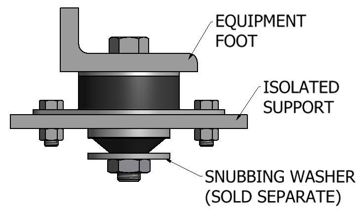
11 Fail-Safe Compression Mounts Fail-Safe Compression Mounts 517 Series 517 SERIES AXIAL LOAD VS. DEFLECTION These fail-safe isolators are ideal for isolation of diesel engines and generators used in construction equipment, recreational vehicles and off-road equipment. The low natural frequency allows them to be used for computer and electronic equipment when there is a need for a ruggedized installation. They are also excellent isolators for compressors, motors, pumps and other machinery when skid mounted. Three sizes available for load ranges of 5 to 55 lbs., High stiffness ratio of 6:1, axialto-radial. Standard elastomer is neoprene, Resistant to ozone, fuel and oils. Temperature range of 2 O F to +18 O F. Optional materials such as nitrile, butyl, silicone and others are available to meet your environmental conditions or military specifications. These mounts are fail-safe when used with snubbing washers and installed as shown. See page 75 for snubbing washers. Part No. Axial Static Load Rating: Nominal (lbs) Color Code Yellow/Gold Red/Gold Green/Gold Blue/Gold White/Gold Yellow/Gold Red/Gold Green/Gold Blue/Gold White/Gold Yellow/Gold Red/Gold Green/Gold Blue/Gold White/Gold INSTALLATION Series Series SERIES AXIAL LOAD VS. DEFLECTION SERIES AXIAL LOAD VS. DEFLECTION


 L (in) W (in) H (in) 52561-2 52562-2 52563-2 52564-2 Black Red Green Gray 15 225 3 4 Note: 52561-2 through 52564-2 have a")

 L (in) W (in) H (in) 52571-2 52572-2 52573-2 52574-2 Black Red Green Gray 15 225 3 4 Note: 52571-2 through 52574-2")
12 Compression Mounts Compression Mounts Standard Deflection Natural Frequecies as low as 6 Hz at maximum loads Constructed of Neoprene and steel Metric threads available Part Numbers 5251 thru are also available in Silicone for an operating temperature range of -8 O to 3 O F. Add -S to part number for silicone. Double Deflection Natural Frequecies as low as 4.5 Hz at maximum loads Constructed of Neoprene and steel Metric threads available Part Numbers thru are also available in Silicone for an operating temperature range of -8 O to 3 O F. Add -S to part number for silicone. Part No Color Code Blue Black Red Green Blue Black Red Green Gray Black Red Green Gray Max. Load (lbs) Max. Deflection (in) L (in) W (in) H (in) Black Red Green Gray Note: through have a rectangular base A (in) B C (in) D (in) E (in).2 3⅛ 1¾ 1 1¼ ⁵/₁₆-18 2⅜ ¹¹/₃₂ ³/₁₆.25 3⅞ 2⅜ 1¼ 1¾ ⅜-16 3 ¹¹/₃₂ ⁷/₃₂.25 5½ 3⅜ 1¾ 2½ ½-13 4⅛ ⁹/₁₆ ¼.25 6¼ 4⅝ 1⅝ 3¾ ½-13 5 ⁹/₁₆ ⅜ Part No Color Code Blue Black Red Green Blue Black Red Green Gray Black Red Green Gray Max. Load (lbs) Max. Deflection (in) L (in) W (in) H (in) Black Red Green Gray Note: through have a rectangular base A (in) B C (in) D (in) E (in).4 3⅛ 1¾ 1¼ 1¼ ⁵/₁₆-18 2⅜ ¹¹/₃₂ ³/₁₆.5 3⅞ 2⅜ 1¾ 1¾ ⅜-16 3 ¹¹/₃₂ ⁷/₃₂.5 5½ 3⅜ 2⅞ 2½ ½-13 4⅛ ⁹/₁₆ ¼.5 6¼ 4⅝ 2¾ 3¾ ½-13 5 ⁹/₁₆ ⅜ 2 21


 Constructed of cold-rolled steel")

13 Compression Mounts Compression Mounts These rugged, high performance mounts are normally used for vertically applied loads to prevent the transmission of noise and vibration caused by the rotation of unbalanced equipment such as centrifuges, blowers, pumps, vibrators and air handling systems. AXIAL LOAD VS DEFLECTION Isolation of disturbing frequencies as low as 15 Hz Neoprene elastomer resistant to oil, fuel, and ozone -2 O to +18 O F operating temperature range AXIAL LOAD VS DEFLECTION Heavy Duty This compression mount design is for applications under heavy industrial machinery requiring efficient vibration, noise, and shock isolation. Typical applications include pumps, compressors, and generators. Low natural frequency of 8-15 Hz Can be mounted in pairs for lower natural frequencies (6-1 Hz) Constructed of cold-rolled steel and oil resistant neoprene AXIAL LOAD VS DEFLECTION Part No. Color Code Load Range (lbs.) W (in.) Part No. Color Code Load Range (lbs.) 5216 Yellow Red Red Green Green Blue Blue White W (in.) Part No. Color Code Max. Load (lbs.) Part No. Color Code Max. Load (lbs.) Red White Green Green Blue Red White

 5254-1 Green 15 5254-2 Blue 2 5254-3 White 3 5254-4 Purple 44 Tech Products spring mounts with aluminum housings are durable enough")

 Static Defl.")

14 Heavy Duty Compression Mounts Spring Mounts Features: High Load Capacity Approx. 8 Hz Natural Frequency at rated load Low Maintenance Constructed of steel and neoprene Resistant to most oils, solvents, and ozone 5:1 vertical to horizontal stiffness ratio Part No. Color Code Max. Load (lbs.) Green Blue White Purple 44 Tech Products spring mounts with aluminum housings are durable enough to handle most of the applications where steel housings are used. The aluminum housing is more weather resistant and lighter. The cast aluminum allows for higher quality thread integrity. The ribbed neoprene pad provides a non-skid base, and neoprene stabilizer pads are included in the housing to control lateral motion. All aluminum housed mounts include one spring with load ratings as high as 13 lbs. Part No. Spring Color Max. Load (lbs) Static Defl Purple Blue Orange Brown Black Yellow Red Green Pink Black Blue Yellow Brown Red Purple Orange Green Gray White L W H A F G J S T ⅜ ½


 Approx. Defl.")
 Approx. Defl. AXIAL LOAD VS DEFLECTION 4 6164 35 3 25 2 15 1 5 Max. Load (lbs) Approx. Defl. 616 Yellow 15.")
15 Low Frequency Mounts Low Frequency Mounts Dimensions and Specifications Low Frequency Mounts unique design bonds a steel spring inside a matrix of oil/ ozone-resistant neoprene. The springs absorb low frequency vibrations, slowing and passing them on to the resilient neoprene. This material made even more stable by the springs interrupts the sound path, prevents noise amplification caused by sounding board effects, and stops vibrations from being transmitted to the floor or work surface. Low Frequency Mounts are made for your toughest vibration applications. They tame the effects of paint mixers, air conditioning units, air compressors and more, indoors and out. There are models for loads from 5 to 4,7 lbs. which exhibit 3.5 Hz natural frequency at maximum load. Typical Mounting Application Part No. Color Code Min. Load (lbs) Approx. Defl. AXIAL LOAD VS DEFLECTION Max. Load (lbs) Approx. Defl Yellow Green White Part No. Color Code Min. Load (lbs) Approx. Defl. AXIAL LOAD VS DEFLECTION Max. Load (lbs) Approx. Defl. 616 Yellow Green White


16 Dome Mounts Dome Mounts COMPRESSION LOAD VS DEFLECTION -4 The interlocking metals of the Dome Mount series result in a fail-safe mount. This feature and low stiffness make them ideal for isolating medium to large size engines as well as fans, blowers, pumps and air handling equipment. They have an approximate natural frequency of 9Hz at maximum load Internal metal components provide fail-safe design Standard neoprene elastomer resistant to oil, fuel, and solvents 9 Hz natural frequency at rated loads Part No. Color Code Max. Load (lbs.) Spring Rate (lbs/in.) Red Green Blue White Red Green Blue L W C B COMPRESSION LOAD VS DEFLECTION White

 and standard neoprene or high damped")
17 Cupmounts Cupmounts Size 1 Size 2 Three Way Protection: Help your sensitive equipment defend itself against high-impact shocks by installing Tech Products Cupmounts. These rugged and versatile mounts also control vibration and interrupt structure-borne noise. Under normal loading conditions, they exhibit natural frequencies of approximately 25 Hz and isolate disturbing frequencies above 35 Hz. Fail-safe Construction: Available in four basic sizes, these compact, low-profile isolators have interlocking components of steel (other metals available) and standard neoprene or high damped silicone elastomers. They can be used to mount your equipment in compression, tension and shear applications. No matter how the mount is oriented or the load is directed, the elastomer is in compression. Land, Sea and Air Uses: Land, Sea and Air Uses: Great resistance to severe shock makes cupmounts ideal for protecting sensitive equipment on roughterrain vehicles or railroad cars. Factories of all types use them for everything from numerically controlled machinery or electronic control panels to blowers. And they stand guard against shock on shipboard equipment, shipping containers, and both aircraft and missile electronics. Features: Compact Fail-Safe Design Capable of mounting in any orientation (compression, shear, tension) Standard Neoprene elastomer for -2 O F to 18 O F Optional High Damped Silicone elastomer for -8 O F to 3 O F Available with standard threads, metric threads, or through-hole cores Zinc Plated steel cap, base, and core Also available with 5/16-18 threads Neoprene Elastomer Part No. High Damped Silicone Elastomer Part No. Maximum Stationary Load (lbs) Vehicular Load Range (lbs) Neoprene Elastomer Part No. High Damped Silicone Elastomer Part No. Maximum Stationary Load (lbs) Vehicular Load Range (lbs)


 Vehicular Load Range (lbs) Neoprene Elastomer Part No.")
 9 6 Neoprene HDS 3 1.7.4.1 1 2 3")
18 Cupmounts Cupmounts Size 3 Size 4 Mounting Configurations Since the elastomer is always in compression, cupmounts operate with equal efficiency in upright, inverted or bulk-head mounting positions, regardless of how the mount is oriented or the load directed. Tech Products Cupmounts Preferred for: Protection against vibration, shock and noise Multi-directional loading Fail-Safe construction Rugged, compact design Load range to 18 pounds Choice of elastomers Neoprene Elastomer Part No. Maximum Stationary Load (lbs) Vehicular Load Range (lbs) Neoprene Elastomer Part No. Maximum Stationary Load (lbs) Vehicular Load Range (lbs) Typical Transmissibility TRANSMISSIBILITY (OUTPUT/INPUT) 9 6 Neoprene HDS FREQUENCY (Hz) Elastomer Data Environment Neoprene Silicone Temperature -2 O to +18 O F -8 O to +3 O F Ozone Resistance Good Excellent Oil Resistance Excellent Good Heat Aging Good Excellent 32 33


19 Stable-Flex Mounts Stable-Flex Mounts 2 AXIAL STIFFNESS CURVES Tech Products Stable Flex Mounts have been specifically engineered to isolate light weight, low speed equipment. The complex geometry of the elastomer element in the mount provides a low axial stiffness and excellent lateral stability. Common Applications include: Small Engines, Generators, Compressors, Pumps, Other Industrial Equipment, and Various Mobile Applications. Features: Fail-Safe Captive Design 8 Hz Natural Frequency at rated loads Load range from 3 to 18 lbs. Neoprene elastomer resistant to oil, fuel, and solvents Standard zinc plated steel components Specialty elastomers available including High Damped Silicone Zinc Plated Part No. Stainless Steel Part No. Rated Axial Load (lbs.) Color Code SS 3 Yellow SS 55 Red SS 75 Green SS 12 Blue SS 18 White Notes: Add 'A' to part number for 3/8-16 Thread Stainless Steel parts have two slotted base holes 34 35

 521-55 145 1.52.9 3.94 4.72 2.36.56.55.43 M12 521-65 22 521-75 265 5211-45 5211-55 465 1.")
20 Heavy Duty Stable-Flex Mounts Heavy Duty Stable-Flex Mounts 521 SERIES AXIAL STIFFNESS The Heavy Duty Stable Flex Mounts Series includes three sizes of captive isolators for rugged applications. The mounts are constructed of zinc plated steel and neoprene. Typical applications include diesel generator sets and marine engines. The mounts offer a low vertical natural frequency of 8 Hz at rated load. Axial stiffness curves are included on the following page. Horizontal stiffness in the long direction is 2.5 times the axial stiffness and in the short direction it is.75 times the axial stiffness. Part No. A B C D E F G H T Max. Load (lbs) M M M SERIES AXIAL STIFFNESS SERIES AXIAL STIFFNESS
21 Standard Bell Mounts Standard Bell Mounts Standard Bell Mounts provide a high level of isolation especially when used on generators, engines and systems with an operating frequency at around 25 Hz (15 rpm). Standard bell mounts are designed with a fail-safe function making it an ideal solution for rugged applications. Part No. Durometer Load Rating (lbs) Spring Rate (lbs/in) Type CFMBH7831W CFMBH7831M CFBMH78312W CFBMH78312M CFBMH92351W CFBMH92351M CFBMH923512W CFBMH923512M CFBMH163812W CFBMH163812M CFBMH163816W CFBMH163816M CFBMH W CFBMH M CFBMH W CFBMH M CFBMH16582W CFBMH16582M CFBMH18662W CFBMH18662M Type 1 Type 2 Part No. A B C D E F G T CFMBH M1 CFBMH M12 CFBMH M1 CFBMH M12 CFBMH M12 CFBMH M16 CFBMH M16 CFBMH M16 CFBMH M2 CFBMH M
. High Deflection bell mounts are designed with a fail-safe function making it an ideal solution for rugged applications.")
 Spring Rate (lbs/in) Type CFBMS83351W 45 18 115 CFBMS83351M 6 4 255 1 CFBMS833512W 45 18 115 CFBMS833512M 6 4 255 1 CFBMS164212W 45 375 19")

22 High Deflection Bell Mounts High Deflection Bell Mounts High Deflection Bell Mounts provide a very high level of isolation when used on generators, engines and systems with operating frequency as low as 15 Hz (9 rpm). High Deflection bell mounts are designed with a fail-safe function making it an ideal solution for rugged applications. Type 1 Type 2 Part No. Durometer Load Rating (lbs) Spring Rate (lbs/in) Type CFBMS83351W CFBMS83351M CFBMS833512W CFBMS833512M CFBMS164212W CFBMS164212M CFBMS164216W CFBMS164216M CFBMS155416W CFBMS155416M CFBMS18862W CFBMS18862M CFBMS221524W CFBMS221524M Part No. A B C D E F G T CFBMS M1 CFBMS M12 CFBMS M12 CFBMS M16 CFBMS M16 CFBMS M2 CFBMS M

 are used Excellent rebound protection Standard Neoprene elastomer resistant to oil, fuel, and solvents Optional")

23 Universal Mounts Universal Mounts 611 thru 15 Series AXIAL STIFFNESS RADIAL STIFFNESS 15 Low-cost, easy-to-install Universal Mounts provide fail-safe, all-attitude isolation for vehicle cabs, engines, transmissions and other equipment up to 455 lbs. in mobile applications. Consisting of two parts an elastomeric ring and an elastomeric bushing bonded to a center metal spacer Universal Mounts are held in place with a through bolt. Part No. A B C D E F Features: Fail-Safe Installation when proper snubbing washers (Page 75) are used Excellent rebound protection Standard Neoprene elastomer resistant to oil, fuel, and solvents Optional elastomers available including High Damped Silicone Thin Support G Thick Support 611 thru N/A thru thru thru thru thru N/A thru N/A.3 R LOAD (LBS) 621 thru 25 Series AXIAL STIFFNESS 12 LOAD (LBS) DEFLECTION (IN) Curves are for recommended THICK support. Consult Tech Products for thin support information 631 thru 35 Series LOAD (LBS) DEFLECTION (INCHES) AXIAL STIFFNESS DEFLECTION (IN) Curves are for recommended THICK support. Consult Tech Products for thin support information LOAD (LBS) LOAD (LBS) LOAD (LBS) DEFLECTION (INCHES) RADIAL STIFFNESS DEFLECTION (IN) RADIAL STIFFNESS DEFLECTION (IN) Static Load Rating (lbs.) Part Color Thin Support No. Code Axial Radial 611 Yellow Red Green Blue White Static Load Rating (lbs.) Part Color Thin Support No. Code Axial Radial 621 Yellow Red Green Blue White Part Color Thick Support No. Code Axial Radial 621 Yellow Red Green Blue White Static Load Rating (lbs.) Part Color Thin Support No. Code Axial Radial 631 Yellow Red Green Blue White 5 37 Part Color Thick Support No. Code Axial Radial 631 Yellow Red Green Blue White
24 Universal Mounts Universal Mounts 641 thru 45 Series LOAD (LBS) AXIAL STIFFNESS DEFLECTION (IN) Curves are for recommended THICK support. Consult Tech Products for thin support information 651 thru 55 Series LOAD (LBS) AXIAL STIFFNESS DEFLECTION (IN) Curves are for recommended THICK support. Consult Tech Products for thin support information LOAD (LBS) RADIAL STIFFNESS DEFLECTION (IN) RADIAL STIFFNESS 12 LOAD (LBS) DEFLECTION (IN) Static Load Rating (lbs.) Part Color Thin Support No. Code Axial Radial 641 Yellow Red Green Blue White Part Color Thick Support No. Code Axial Radial 641 Yellow Red Green Blue White Static Load Rating (lbs.) Part Color Thin Support No. Code Axial Radial 651 Yellow Red Green Blue White Part Color Thick Support No. Code Axial Radial 651 Yellow Red Green Blue White thru -5 Series LOAD (LBS) AXIAL STIFFNESS DEFLECTION (IN) thru -5 Series LOAD (LBS) AXIAL STIFFNESS DEFLECTION (IN) LOAD (LBS) RADIAL STIFFNESS LOAD (LBS) DEFLECTION (IN) RADIAL STIFFNESS DEFLECTION (IN) Static Load Rating (lbs.) Part No. Color Thin Support Code Axial Radial Yellow Red Green Blue White Static Load Rating (lbs.) Part No. Color Thin Support Code Axial Radial Yellow Red Green Blue White

 Load (lbs.) Code 6285-1 1 18 Yellow 6285-2 175 275 Red 6285-3 225 4 Green 6285-4 32 5 Blue 6285-5 42 7 White 8 6 4 2.")
 Code 6278-1 215 8 Yellow 6278-2 36 12 Red 6278-3 49 175 Green 6278-4 86 265 Blue 6278-5 133 37 White RADIAL LOAD VS DEFLECTION 45-5 4 35 3 25 2 15 1 5.1.2.3.4.5.6-4 -3-2 -1 46 47")
25 Wear Plate Universal Mounts Wear Plate Universal Mounts 6272 Series AXIAL LOAD VS DEFLECTION Series AXIAL LOAD VS DEFLECTION RADIAL LOAD VS DEFLECTION RADIAL LOAD VS DEFLECTION Part No. Max. Axial Max. Radial Color Load (lbs.) Load (lbs.) Code Yellow Red Green Blue White 6278 Series AXIAL LOAD VS DEFLECTION Part No. Max. Axial Max. Radial Color Load (lbs.) Load (lbs.) Code Yellow Red Green Blue White Part No. Max. Axial Max. Radial Color Load (lbs.) Load (lbs.) Code Yellow Red Green Blue White RADIAL LOAD VS DEFLECTION


26 Armor Plated Universal Mounts Armor Plated Universal Mounts The Armor Plated Universal Mount can be used in the same applications as the standard Universal Mounts. But since it has bonded-in steel wear surfaces, it can be used in more extreme environments. These steel wear surfaces eliminate the need for machining a radius in the support structure. Fail-Safe installation when snubbing washers (Page 75) are used 8-1 Hz natural frequency at rated load Oil, Fuel, and Solvent resistant Neoprene elastomer -2 O F to 18 O F operating temperature range Part No. Color Code Max. Radial Load (lbs.) Max. Axial Load (lbs.) Yellow Red Green Blue White
 632-1 Yellow 9 632-2 Red 15 632-3 Green 21 632-4 Blue 3 632-5 White 4 8 7 632 AXIAL LOAD VS. DEFLECTION -5 14 12 632 RADIAL LOAD VS.")

 are used 8-1 Hz natural frequency at rated load Oil, Fuel, and Solvent resistant Neoprene elastomer -2 O F to 18 O F operating temperature range")
27 Self-Snubbing Universal Mounts Self-Snubbing Universal Mounts 632 Series Part No. Color Code Max. Axial Load (lbs.) Yellow Red Green Blue White AXIAL LOAD VS. DEFLECTION RADIAL LOAD VS. DEFLECTION -5 Self-Snubbing Universal Mounts include an internal metal cup that acts as a overload protection. This design protects the isolator from excessive compression in applications where high torque forces or shock inputs are expected. Typical applications include diesel engines, transmissions, and operator cabs. Fail-Safe installation when snubbing washers (Page 75) are used 8-1 Hz natural frequency at rated load Oil, Fuel, and Solvent resistant Neoprene elastomer -2 O F to 18 O F operating temperature range Series Part No. Color Code Max. Axial Load (lbs.) Yellow Red Green Blue White AXIAL LOAD VS. DEFLECTION RADIAL LOAD VS. DEFLECTION NOTE: Part numbers are for individual bushings. Bushings should be ordered and installed in pairs Part No. A B C D E F G 632 Series Series

 are used 1:1 Axial to Radial Stiffness Ratio 8.")
 5155-1 Yellow 38 N/A 5155-2 Red 6 N/A 5155-3 Green 9 N/A 5156-1 Yellow 75 N/A 5156-2 Red 15 N/A 5156-3 Green 15 N/A 5157-1 Red 15 1 5157-2 Green 2 15 5157-3 Blue 27 18 5157-4 White")

28 515 Series Mounts 515 Series Mounts 5155 Series AXIAL LOAD VS. DEFLECTION Compact 515 Series all-attitude mounts are a money-saving way to protect equipment from vibration and shock. High load capacity, stability, and the ability to be installed at any mounting angle make them ideal for a wide variety of applications, including vehicle cabs; truck, bus and marine engines; generators; air conditioning units; motors and electronic equipment. Features All-Attitude design allows for mounting at any angle Fail-Safe Installation when proper snubbing washers (Page 75) are used 1:1 Axial to Radial Stiffness Ratio 8.5 Hz Natural Frequency at maximum load Oil, fuel, and solvent resistant Neoprene Temperature Range: 2 O to +18 O F Part No. Color Max. Axial Max Radial Code Load (lbs.) Load (lbs.) Yellow 38 N/A Red 6 N/A Green 9 N/A Yellow 75 N/A Red 15 N/A Green 15 N/A Red Green Blue White Yellow Red Green Blue White Yellow Red Green Blue White Yellow Red Green Blue White Red Green Blue White Series 5157 Series AXIAL LOAD VS. DEFLECTION


29 515 Series Mounts 515 Series Mounts 5158 Series Series 5151 Series Typical Installation Series 54 55

 are used Oil, Fuel, and Solvent resistant neoprene elastomer -2 O F to")
 G H I R(min.) T327.38.55 1.7.4 1.")
 622 thru 23.31.23.69.4 1.1.81.75 1.9.6 623 thru 33.38.41 1..47 1.5 1.24 1.12 1.75.6 6235 thru 38.62.53 1.38.53 1.7 1.35 1.25 2..6 624 thru 43.62.53 1.38.64 1.7 1.35 1.25 2..6 6245 thru 48.")
30 Center Bushing Mounts Center Bushing Mounts Tech Products Center Bushing Mounts are fail-safe, multi-direction isolators for a variety of heavy duty applications. During Installation, a self-contained rebound is formed when the mounts resilient element spreads under compression. An internal sleeve serves as a positive spacer to control pre-loading. Features Single piece design for easy installation Fail-Safe Installation when proper snubbing washers (Page 75) are used Oil, Fuel, and Solvent resistant neoprene elastomer -2 O F to 18 O F operating temperature range This series of Center Bushing Mounts is designed with more rubber underneath the mounting structure for more rebound protection. They also offer higher deflection than the standard series for better isolation of lower frequency vibration. Large Rebound Series Part No. A B C D F(min.) G H I R(min.) T T T Standard Series Part No. A B C D F(min.) G H I R(min.) 622 thru thru thru thru thru thru thru Load ratings and Stiffness Curves for Center Bushing Mounts are on the next two pages
31 Center Bushing Mounts Center Bushing Mounts Part No. Color Code Max. Load (lbs.) 622 Red Green Blue White 14 AXIAL LOAD VS DEFLECTION Part No. Color Code Max. Load (lbs.) 623 Red Green Blue White 52 AXIAL LOAD VS DEFLECTION Part No. Color Code Max. Load (lbs.) T327W Blue 1 T327M None 2 AXIAL LOAD VS DEFLECTION 2 T327M T327W Part No. Color Code Max. Load (lbs.) T5137K None 3 T5137H White 4 AXIAL LOAD VS DEFLECTION T5137H T5137K Part No. Color Code Max. Load (lbs.) 6235/624 Red /6241 Green /6242 Blue /6243 White 72 AXIAL LOAD VS DEFLECTION Part No. Color Code Max. Load (lbs.) 6245 Red Green Blue White 11 AXIAL LOAD VS DEFLECTION Part No. Color Code Max. Load (lbs.) T638K None 5 T638H Orange 65 AXIAL LOAD VS DEFLECTION T638H T638K Part No. Color Code Max. Load (lbs.) Orange Yellow 15 AXIAL LOAD VS DEFLECTION Part No. Color Code Max. Load (lbs.) 625 Red Green Blue White 15 Part No. Color Code Max. Load (lbs.) 626 Red Green Blue White 24 AXIAL LOAD VS DEFLECTION AXIAL LOAD VS DEFLECTION


 Oil and ozone resistant neoprene 8-1 Hz natural frequency Part No. Axial Load Rating (lbs.")
32 Heavy Duty Platemounts Heavy Duty Platemounts Tech Products Heavy Duty Plate Mounts provide excellent vibration isolation for applications where a low natural frequency is required. At rated loads, these mounts provide a natural frequency below 7 Hz. Typical applications include gas and diesel engines, generator sets, pumps, compressors, and many other types of mobile equipment Series Series Fail-safe when installed with snubbing washers (Page 75) Standard neoprene elastomer resistant to oil, fuel, and most solvents Two sizes available for loads ranging from 85 to 425 lbs. Natural Frequency below 7 Hz at rated loads 2.5 Radial to Axial Stiffness ratio Tech Products Series isolators provide excellent vibration and shock protection for a variety of applications including small engines, generators, compressors, pumps, and other mobile equipment. Features: Compact Fail-Safe Design (see Page 75 for Snubbing Washers) Oil and ozone resistant neoprene 8-1 Hz natural frequency Part No. Axial Load Rating (lbs.) Color Code Yellow Red Green Blue White AXIAL STIFFNESS -5 Part No. Max. Axial Load (lbs.) Color Code Part No. Max. Axial Load (lbs.) Color Code Yellow Red Red Green Green Blue Blue White Deflection at Maximum Load =.25 Radial Stiffness = 2.5 x Axial Stiffness LOAD (POUNDS) DEFLECTION (INCHES)
 5744-1 1 5744-15 15 5744-2 2 14 12-2 Tech Products 57 Series Mounts are general purpose isolators for equipment mounted in aircraft, shipboard, or")


 1 8 6 4 2.4.8.12.16 DEFLECTION (INCHES) -15-1 5764 Series 5722 Series Part Number Max. Load (lbs.")
33 57 Series Mounts 57 Series Mounts 5744 Series Part Number Max. Load (lbs.) Tech Products 57 Series Mounts are general purpose isolators for equipment mounted in aircraft, shipboard, or vehicular applications. These mounts are designed to isolate high frequency vibration and the high damped silicone elastomer provides good shock attenuation and low resonant amplification. The three different sizes are designed to support load ranges from 1 to 8 lbs. Fail-Safe, All-Attitude Design 1:1 Axial to Radial Stiffness Isolation of Vibration over 4 Hz 4. Max. Transmissibility at Resonance High Damped Silicone Elastomer -8 o F to 3 o F Temperature Range Height (H) Compressed 1.19 Approx. Free 1.5 Max. Extended 1.88 LOAD (POUNDS) DEFLECTION (INCHES) Series 5722 Series Part Number Max. Load (lbs.) Part Number Max. Load (lbs.) Height (H) Compressed.91 Approx. Free 1.22 Max. Extended 1.56 LOAD (POUNDS) DEFLECTION (INCHES) Height (H) Compressed 1.25 Approx. Free 1.62 Max. Extended 1.94 LOAD (POUNDS) DEFLECTION (INCHES)

34 All-Attitude Mounts All-Attitude Mounts Tech Products Series elastomeric mounts have an aluminum center plate suited for built-in electronics. The Series is a holder style for applications where a base mounted configuration is needed. The elastomer in compression design assures effective isolation in all directions. The highly damped silicone elastomer provides optimum vibration isolation over a temperature range of -8 O to 3 O F. The radial to axial stiffness ratio is approximately.6. Features All-Attitude design for mounting in any orientation Capable of withstanding 3g, 11 millisecond shock loads High Damped Silicone elastomer Holder style available for base mounting installation 522 Series All-Attitude isolators protect stationary loads of 15-5 lbs. and vehicular loads up to 3 lbs. from vibration, shock and noise. Neoprene elastomer is standard, but High Damped Silicone (HDS) is also available to meet application needs. Neoprene models have a temperature range of -2 O to 18 O F with excellent resistance to oil and ozone. The HDS models have a temperature range of -8 O to 3 O F and a maximum transmissibilty of about 3.5. Features Elastomer in compression design for multi-axis loading Standard neoprene elastomer High Damped Silicone Available Capable of withstanding high shockloads (see vehicular load ratings) Axial Stiffness Axial Stiffness Part No. Color Code Max. Stationary Load (lbs.) Gray Red Yellow Green 1. Part No. Color Code Max. Stationary Load (lbs.) 5225 Red Green Yellow Blue


 62434-6P Yellow 6 62434-6 Yellow 6 62434-9P Red 9 62434-9 Red 9")

35 Platemounts Platemounts Fail-safe operation of electronic and electromechanical equipment, appliances, office machines and transportation equipment are typical applications for Tech Products Plate Mounts. Designed for light to medium loads, they isolate mounted equipment from external vibration and/or isolate vibration produced by the mounted equipment itself. Plate Mounts feature steel and natural rubber which operate at temperatures of -2 O to 18 O F. Part numbers are shown for steel plates. Aluminum plates and neoprene elastomer are available options. Part No. Color Code Max. Load (lbs.) Yellow Red Green Blue White 6 Deflection at Max. Load =.18 Square Shape Diamond Shape Part No. Color Code Max. Load (lbs.) Part No. Color Code Max. Load (lbs.) P Yellow Yellow P Red Red P Green Green P Blue Blue 16 Deflection at Max. Load =.18 Square Shape Diamond Shape Part No. Color Code Max. Load (lbs.) Part No. Color Code Max. Load (lbs.) Yellow Yellow Red Red Green Green Blue Blue Blue-White Blue-White 6 Deflection at Max. Load =
 Part No. Color Code Max. Load (lbs.) 6249-A Yellow.")

 Part No.")
 6213 Yellow 3 62123 Yellow 3 6216 Red 6 62166 Red 6 6219 Red-Green 9 62129")

 Part No.")


36 Platemounts Platemounts Square Shape Diamond Shape Part No. Color Code Max. Load (lbs.) Part No. Color Code Max. Load (lbs.) 6249-A Yellow A Yellow Red Red Green Green Blue Blue White White 6 Deflection at Max. Load =.6 Square Shape Diamond Shape Part No. Color Code Max. Load (lbs.) Part No. Color Code Max. Load (lbs.) 6213 Yellow Yellow Red Red Red-Green Red-Green Green Green Green-Blue Green-Blue Blue Blue Blue-White Blue-White Blue-Yellow Blue-Yellow 26 Deflection at Max. Load =.9 Square Shape Diamond Shape Part No. Color Code Max. Load (lbs.) Part No. Color Code Max. Load (lbs.) 624 Yellow Yellow Red Red Green Green Blue Blue 2 Deflection at Max. Load =.6 Square Shape Diamond Shape Part No. Color Code Max. Load (lbs.) Part No. Color Code Max. Load (lbs.) 6233 Red Red Red-Green Red-Green Green Green Green-Blue Green-Blue Blue Blue 9 Deflection at Max. Load =.13 Available with 3/8-16 threaded core 68 69

37 Ring and Bushing Mounts Ring and Bushing Mounts Neoprene Ring and Bushing Mounts are incorporated directly into the structural components of equipment such as office machines, motors and pumps, as well as air conditioning, electronic and scientific equipment. They offer fail-safe operation when installed in pairs. Opposing holes in the elastomer provide excellent low-frequency isolation. The location of the holes cushions shock and isolates vibration parallel to the mount axis. The bushing s holes isolate vibration perpendicular to its axis. Features Fail-Safe installation when proper snubbing washers and spacers are used Neoprene elastomer resistant to oil, fuel, and solvents Three sizes for loads ranging from 1 to 1 lbs. Operating temperature range of -2 O F to 18 O F Ring Part No. Bushing Part No. Color Code Max. Load (lbs.) Silver Yellow Red Green Blue White 3 Ring Part No. Bushing Part No. Color Code Max. Load (lbs.) Silver Yellow Red Green Blue White 65 Typical Mounting Application Ring Part No. Bushing Part No. Color Code Max. Load (lbs.) Silver Yellow Red Green Blue White


38 Bubble Mounts High Deflection Silicone Mounts Features: High Damped Silicone Elastomer Lightweight Aluminum metal components 1:1 Axial to Radial stiffness ratio -8 O F to 3 O F operating temperature range Low-frequency Bubble Mounts isolate electronic or medical equipment, avionics, computers, small pumps and compressors, and more from shock and vibration. Easy-to-install Bubble Mounts are primarily recommended for compression loads. Small compact design Excellent isolation of light loads 8 Hz Natural Frequency at rated loads Standard Neoprene elastomer resists oil, ozone, and most solvents Optional silicone elastomer available for extreme high or low temperatures Part No. Color Code Max. Load (lbs.) 564 Yellow Red Green Blue White Yellow Red Green Blue White 18. A The High Deflection Silicone mounts are low profile isolators that have large deflection capability for shock and vibration attenuation. The mounts are designed to support loads ranging from 5 to 15 lbs. Retaining straps are available for fail-safe installation. Typical applications include ruggedized electronics and computer equipment AXIAL STIFFNESS A -2A -1A LOAD (LBS.) Axial Stiffness Part Number Load Range (lbs.) A A A 1-15 RADIAL STIFFNESS A -2A -1A 72 73


 Min. Max. A B C D E F G H* J K T 521 2 1 3. 2.38.31 3/8-16.47.27 2.89 2.5 1.9 1.94.12 522 1 3 4.19 3.5.34 1/2-13.54.29 4.14 2.5 2.6 1.94.12 523 3 55 5.13 4.25.44 1/2-13.54.29 4.99 3.")
39 Pneumatic Spring Mounts Snubbing Washers Material: Steel Finish: Zinc Plating Tech Products Pneumatic series are air spring mounts particularly well suited for situations requiring high deflection and natural frequencies as low as 2.75 Hz. The high stability and reliability of this mount is ideal for use in mounting vibrators, shakers, vacuum pumps, optical comparators, HVAC equipment and equipment subjected to low frequency shock and/or vibration. Features: Thick walled elastomeric construction Dynamic overload capacity of up to ten times maximum rated static load in compression Designed for air pressures of 2-85 psi Low Natural Frequency Part No. Load (lbs.) Min. Max. A B C D E F G H* J K T / / / / / / * H = Free Height; H+1/4 = nominal loaded height for steady force applications Product Washer P/N A B T 5155-( ) ( ) ( ) ( ) ( ) ( ) ( ) ( ) ( ) ( ) to to to to to ( ) ( ) to to to to to to to ( ) ( ) ( ) ( ) ( ) ( ) ( ) ( ) ( ) ( ) T327( ) T5137( ) T638( )

40 Stud/Plate Mounts Stud/Plate Mounts (6-32) Tech Products offers one of the industry s largest selections of these multi-purpose mounts. Stud/Plate mounts are known throughout the industry by several names including: bumpers, snubbers, feet, sandwich mounts, shockmounts, shearmounts, cylindrical mounts, isolators, levelers, and insulators. Tech Products offers other sizes of mounts which may not be shown. Please contact us if you cannot find a specific size needed or if you need assistance selecting the proper mount. Features: Many sizes available from stock Standard and metric thread sizes available Elastomer options include natural rubber, neoprene, silicone and more Corrosion resistant zinc plated inserts Available in load ratings from 1 to 12 lbs. Visit for a searchable database of Tech Products Stud/Plate Mounts. Maximum Tightening Torque UNC Thread lbs-inch / / / / Note: Do not twist elastomer during installation Style PP Part No. D M P (Depth) Max. Shear (lbs.) Max. Comp. (lbs.) 598 3/8 1/ (1/8) * 9/16 1/ (1/8) * 9/16 1/ (1/8) * 9/16 1/ (1/8) 9 26 Standard elastomer is Natural Rubber, (*) indicates Neoprene Style PS Part No. D M 6-32 x S P (Depth) Max. Shear (lbs.) Max. Comp. (lbs.) 5168* 3/8 3/8 1/ (5/32)# * 3/8 5/16 1/ (5/32) * 3/8 5/16 3/ (5/32) * 3/8 5/16 3/ (5/32) /16 13/32 1/ (1/8) * 7/16 13/32 1/ (1/8) * 7/16 13/32 1/ (1/8) * 7/16 1/2 3/ (5/32)# * 7/16 1/2 3/ (5/32)# * 7/16 1/2 1/ (5/32)# * 7/16 1/2 1/ (1/8)# * 7/16 5/8 1/ (1/8) * 7/16 3/4 1/ (1/8) Standard elastomer is Natural Rubber, (*) indicates Neoprene (#) indicates blind insert Style SS Part No. D M 6-32 x S Max. Shear (lbs.) Max. Comp. (lbs.) /16 13/32 1/ /16 13/32 1/ /16 13/32 3/8-1/

 Max. Comp. (lbs.) 5111 7/16 1/2 8-32 - 4.5 51112 7/16 1/2 8-32 - 8 516 9/16 1/2 8-32 - 9.")
41 Stud/Plate Mounts (8-32) Stud/Plate Mounts (8-32) Part No. D (Square) M 8-32 x S Max. Shear (lbs.) Max. Comp. (lbs.) 517* 3/8 5/16 3/ /8 5/16 7/ /8 5/16 7/ /8 5/16 7/ * 3/8 5/16 3/8-9/ * 3/8 5/16 7/ /8 5/16 3/ /8 5/16 3/ * 3/8 5/16 7/ /8 5/16 7/32-9/ /8 1/2 7/ /8 1/2 3/ /8 1/2 3/ /8 1/2 3/ /8 1/2 3/ Standard elastomer is Natural Rubber, (*) indicates Neoprene Style P Part No. D M P Max. Shear (lbs.) Max. Comp. (lbs.) /16 1/ /16 1/ /16 1/ /16 1/ P thread depth is minimum one thread diameter Style PP Part No. D M P Max. Shear (lbs.) Max. Comp. (lbs.) 511 7/16 1/ /16 1/ /16 1/ /16 1/ /16 1/ /16 1/ * 9/16 1/ P thread depth is minimum one thread diameter Part No. D (Square) E (Dia.) M N 8-32 x S Max. Shear (lbs.) Max. Comp. (lbs.) /2 3/8 9/16 3/8 9/ /2 3/8 9/16 3/8 9/ * 1/2 3/8 9/16 3/8 9/ * 1/2 3/8 9/16 3/8 9/ Standard elastomer is Natural Rubber, (*) indicates Neoprene Style PS Part No. D M 8-32 x S P Max. Shear (lbs.) Max. Comp. (lbs.) 519 7/16 1/2 3/ /16 1/2 3/ /16 1/2 1/ /16 1/2 1/ /16 1/2 3/ /16 1/2 3/ * 9/16 1/2 3/ /16 1/2 3/8 8-32# /16 1/2 3/ Standard elastomer is Natural Rubber, (*) indicates Neoprene P thread depth is minimum one thread diameter (#) indicates blind insert 78 79
42 Stud/Plate Mounts (8-32) Stud/Plate Mounts (1-32) Style S Part No. D M 8-32 x S Max. Shear (lbs.) Max. Comp. (lbs.) /16 1/2 3/ /16 1/2 3/ /16 1/2 3/ /16 1/2 3/8-18 Style SS Part No. D M 8-32 x S Max. Shear (lbs.) Max. Comp. (lbs.) /8 1/2 3/ /8 1/2 3/ /8 1/2 3/ /8 1/2 3/ * 3/8 1/2 3/ * 3/8 1/2 3/ * 3/8 1/2 3/ * 3/8 1/2 3/ * 3/8 1/2 3/ /16 1/2 3/ /16 1/2 3/ * 7/16 1/2 3/ * 7/16 1/2 3/ /16 1/2 3/ /16 1/2 3/ * 9/16 1/2 3/ * 9/16 1/2 3/ /16 1/2 1/ * 9/16 1/2 1/ Style PS Part No. D M S P Max. Shear (lbs.) Max. Comp. (lbs.) /16 1/ x 3/ /16 1/ x 3/ * 9/16 1/ x 3/ /16 1/ x 3/ /16 1/ x 3/ / x 3/ P thread depth is minimum one thread diameter Style SS Part No. D M 1-32 x S Max. Shear (lbs.) Max. Comp. (lbs.) 5137* 9/16 1/2 3/ /16 1/2 3/8-3/ /16 1/2 3/ /4 3/ Standard elastomer is Natural Rubber, (*) indicates Neoprene Standard elastomer is Natural Rubber, (*) indicates Neoprene 8 81
43 Stud/Plate Mounts (1/4-2) Stud/Plate Mounts (1/4-2) Style P Part No. D M P Max. Shear (lbs.) Max. Comp. (lbs.) 5125* 3/4 1/2 1/ * 1 17/32 1/ /4 1/ P thread depth is minimum one thread diameter Style S Part No. D M 1/4-2 x S Max. Shear (lbs.) Max. Comp. (lbs.) 51494* 3/4 1/2 3/ /32 3/ /32 3/ /32 3/ /64 1/ /4 1/ /4 1/ * 1 3/4 7/ * 1 27/32 3/ * 1 1 1/ / / * 1 1 3/ * 1 ¼ 3/4 5/ * 1 ¼ 1 1/4-7 Standard elastomer is Natural Rubber, (*) indicates Neoprene Style SS Part No. D M 1/4-2 x S Max. Shear (lbs.) Max. Comp. (lbs.) 582* 3/4 1/2 1/ * 1 3/8 1/ * 1 17/32 1/ /32 3/ /32 3/ /32 1/2-1/ /32 1/ /32 1/ /32 1/ * 1 1/2 1/ * 1 3/4 3/ * 1 3/4 3/ /4 1/ /4 1/ /4 1/ * 1 3/4 1/ * 1 3/4 1/ * 1 3/4 1/ * 1 3/4 1/ /4 5/ * 1 3/4 5/ * 1 3/4 3/ /4 3/ * 1 3/4 3/ /4 3/ * 1 3/4 3/ * 1 3/4 1/4-5/ /4 3/8-1/ * 1 3/4 1/2-3/ * 1 3/4 1/2-3/ * 1 3/4 1/2-3/ /4 1/ * 1 1 1/ * 1 ⅛ 1 ½ 5/ ¼ 1 ¼ 5/8 3 8 Standard elastomer is Natural Rubber, (*) indicates Neoprene Standard inserts are zinc plated 82 83
44 Stud/Plate Mounts (1/4-2) Stud/Plate Mounts (5/16-18) Style PP Part No. D M P Max. Shear (lbs.) Max. Comp. (lbs.) /4 1/ /4 1/ P thread depth is minimum one thread diameter Style PS Part No. D M 1/4-2 x S P Max. Shear (lbs.) Max. Comp. (lbs.) 5823* 5/8 5/8 1/2 1/ * 3/4 1/2 1/2 1/ * 3/4 1/2 1/2 1/ * 3/4 1/2 1/2 1/ * 3/4 1/2 1/2 1/ * 1 1/2 1/2 1/ * 1 17/32 1/2 1/ * 1 3/4 1/2 1/ * 1 3/4 3/8 1/ * 1 3/4 3/8 1/ /4 1/2 1/ /4 1/2 1/ /4 1/2 1/ * 1 3/4 1/2 1/ * 1 3/4 1/2 1/ /4 3/4 1/ /2 1/ * 1 1 1/2 1/ * 1 1 3/4 1/ Standard elastomer is Natural Rubber, (*) indicates Neoprene P thread depth is minimum one thread diameter Style PS Part No. D M 5/16-18 x S P Max. Shear (lbs.) Max. Comp. (lbs.) 51283* 1 1/2 9/16 5/ * 1 1/2 9/16 5/ * 1 1/2 9/16 5/ * 1 1/2 9/16 5/ *^ 1 3/4 3/8 5/ /4 1/2 5/ /4 9/16 5/ * 1 3/4 5/16 5/ * 1 3/4 5/16 5/ * 1 3/4 5/16 5/ * 1 3/4 5/16 5/ * 1 ¼ 1 3/4 5/ * 1 ¼ 1 3/4 5/ * 1 ¼ 1 ¼ 9/16 5/ * 1 ¼ 1 ¼ 9/16 5/ * 1 ¼ 1 ¼ 9/16 5/ * 1 ¼ 1 ¼ 9/16 5/ * 1 ¼ 1 ¼ 3/4 5/ * 1 ¼ 1 ¼ 3/4 5/ ⅜ 1 9/16 5/ *^ 1 ⅜ 1 9/16 5/ * 1 ⅜ 1 ½ 5/8 5/ * 1 ⅜ 1 ½ 5/8 5/ ½ 1 9/16 5/ ½ 1 9/16 5/ ½ 1 9/16 5/ ½ 1 9/16 5/ * 1 ½ 1 5/8 5/ * 1 ½ 1 9/16 5/ Standard elastomer is Natural Rubber, (*) indicates Neoprene P thread depth is minimum one thread diameter Standard inserts are zinc plated, (^) indicates phosphate finish 84 85
45 Stud/Plate Mounts (5/16-18) Stud/Plate Mounts (5/16-18) Style SS Part No. D M 5/16-18 x S Max. Shear (lbs.) Max. Comp. (lbs.) 5852*^ 1 1/2 5/ /4 3/ * 1 3/4 3/ /4 9/ /4 9/ /4 9/ /4 5/ /4 3/ /4 3/ /4 3/ * 1 3/4 9/ * 1 3/4 1/2-7/ * 1 3/4 1/2-7/ * 1 3/4 1/2-7/ * 1 1 9/ / / / / /2-3/ / ½ 5/ ½ 5/ * 1 ¼ 3/4 9/ ¼ 3/4 9/ ¼ 3/4 9/ ¼ 3/4 9/ ¼ 3/4 9/ * 1 ¼ 3/4 1/2-3/ ¼ 3/4 3/ ¼ 3/4 3/ ¼ 3/4 3/ ¼ 3/4 5/ ¼ 1 9/ ¼ 1 9/ Standard elastomer is Natural Rubber, (*) indicates Neoprene Standard inserts are zinc plated, (^) indicates phosphate finish Style SS Part No. D M 5/16-18 x S Max. Shear (lbs.) Max. Comp. (lbs.) ¼ 1 3/ ¼ 1 3/ * 1 ¼ 1 ¼ 5/ * 1 ¼ 1 ¼ 5/ * 1 ¼ 1 ¼ 5/ ¼ 1 ¼ 9/ ¼ 1 ¼ 9/ ¼ 1 ¼ 9/ ¼ 1 ¼ 3/ ¼ 1 ¼ 3/ * 1 ¼ 1 ¼ 9/ * 1 ¼ 1 ¼ 7/ ¼ 1 ¼ 7/ ¼ 1 ¼ 3/ * 1 ⅜ 5/8 5/ * 1 ⅜ 5/8 5/ * 1 ⅜ 5/8 5/ * 1 ⅜ 5/8 5/ * 1 ⅜ 5/8 5/ * 1 ⅜ 1 1 1/ ⅜ 1 9/ ⅜ 1 9/ ⅜ 1 9/ ⅜ 1 9/ ⅜ 1 7/ * 1 ⅜ 1 3/ * 1 ⅜ 1 3/ * 1 ⅜ 1 3/ * 1 ⅜ 1 3/ * 1 ⅜ 1 3/ ⅜ 1 3/ *^ 1 ⅜ 1 3/ * 1 ½ 1 5/ * 2 1 ¾ 5/ * 2 1 ¾ 5/ Standard elastomer is Natural Rubber, (*) indicates Neoprene Standard inserts are zinc plated, (^) indicates phosphate finish 86 87
46 Stud/Plate Mounts (5/16-18) Stud/Plate Mounts (3/8-16) Style PP Part No. D M P Max. Shear (lbs.) Max. Comp. (lbs.) 51272* 1 1 5/ * 1 1 5/ ¼ 1 ¼ 5/ ¼ 1 ¼ 5/ ¼ 1 ¼ 5/ * 1 ⅜ 1 5/ P thread depth is minimum one thread diameter Style P Part No. D M P Max. Shear (lbs.) Max. Comp. (lbs.) /4 5/ ¼ 3/4 5/ P thread depth is minimum one thread diameter Style S Part No. D M 5/16-18 x S Max. Shear (lbs.) Max. Comp. (lbs.) 5983^ 1 3/8 1 1/ /32 9/ /4 5/ ^ 1 3/4 1 1/ / ¼ 3/4 3/ ¼ 3/4 3/ * 1 ¼ 3/4 9/ * 1 ¼ 3/4 1/ * 1 ¼ 1 9/ ¾ 3/ ¾ 3/ ¾ 3/ ¾ 3/ ¾ 3/4-325 Standard elastomer is Natural Rubber, (*) indicates Neoprene Standard inserts are zinc plated, (^) indicates phosphate finish Style PS Part No. D M 3/8-16 x S P Max. Shear (lbs.) Max. Comp. (lbs.) 51588* 1 ½ 7/8 5/8 3/ ½ 1 5/8 3/ ½ 1 5/8 3/ ½ 1 5/8 3/ ½ 1 5/8 3/ ½ 1 5/8 3/ * 2 ½ 1 7/8 3/ * 2 ½ 1 7/8 3/ * 2 ½ 1 7/8 3/ * 2 ½ 1 7/8 3/ * 2 ½ 1 7/8 3/ P thread depth is minimum one thread diameter Style SS Part No. D M 3/8-16 x S Max. Shear (lbs.) Max. Comp. (lbs.) ½ 1 5/ ½ 1 5/ ½ 1 5/ ½ 1 5/ ½ 1 5/ ½ 1 3/ ½ 1 3/ ½ 1 3/ * 1 ½ 1 3/ * 1 ½ 1 3/ ½ 1 7/ ½ 1 7/ ½ 1 7/ ½ 1 7/ ½ 1 7/ Standard elastomer is Natural Rubber, (*) indicates Neoprene 88 89
 Max. Comp. (lbs.")
47 Stud/Plate Mounts (1/2-13) Stud/Plate Mounts (1/2-13) Style PP Part No. D M P (Depth) Max. Shear (lbs.) Max. Comp. (lbs.) 51415* 2 1 ¹¹/₁₆ 1/2-13 (1/2)# * 2 1 ¹¹/₁₆ 1/2-13 (1/2)# * 2 1 ¹¹/₁₆ 1/2-13 (1/2)# * 2 1 ¹¹/₁₆ 1/2-13 (1/2)# * 2 1 ¹¹/₁₆ 1/2-13 (1/2)# * 3 ⅛ 1 ½ 1/2-13 (1/2) * 3 ⅛ 1 ½ 1/2-13 (1/2) * 3 ⅛ 1 ½ 1/2-13 (1/2) * 3 ⅛ 1 ½ 1/2-13 (1/2) * 3 ⅛ 1 ½ 1/2-13 (1/2) * 3 ⅛ 3 1/2-13 (1/2) * 3 ⅛ 3 1/2-13 (1/2) * 3 ⅛ 3 1/2-13 (1/2) * 3 ⅛ 3 1/2-13 (1/2) * 3 ⅛ 3 1/2-13 (1/2) Style PS Part No. D M 1/2-13 x S P Max. Shear Max. Comp * 1 ¼ 1 ¼ 3/4 1/2-13 (3/8) * 1 ¼ 1 ¼ 3/4 1/2-13 (3/8) * 2 1 ¹¹/₁₆ 1 ⅛ 1/2-13 (1/2)# * 2 1 ¹¹/₁₆ 1 ⅛ 1/2-13 (1/2)# * 2 1 ¹¹/₁₆ 1 ⅛ 1/2-13 (1/2)# * 2 1 ¹¹/₁₆ 1 ⅛ 1/2-13 (1/2)# * 2 1 ¹¹/₁₆ 1 ⅛ 1/2-13 (1/2)# * 3 ⅛ 1 ½ 1 ⅝ 1/2-13 (1/2) * 3 ⅛ 1 ½ 1 ⅝ 1/2-13 (1/2) * 3 ⅛ 1 ½ 1 ⅝ 1/2-13 (1/2) * 3 ⅛ 1 ½ 1 ⅝ 1/2-13 (1/2) * 3 ⅛ 1 ½ 1 ⅝ 1/2-13 (1/2) * 3 ⅛ 3 1 ⅝ 1/2-13 (1/2) * 3 ⅛ 3 1 ⅝ 1/2-13 (1/2) * 3 ⅛ 3 1 ⅝ 1/2-13 (1/2) * 3 ⅛ 3 1 ⅝ 1/2-13 (1/2) * 3 ⅛ 3 1 ⅝ 1/2-13 (1/2) Style SS Part No. D M 1/2-13 x S Max. Shear (lbs.) Max. Comp. (lbs.) ¼ 1 ¼ 3/ * 1 ¼ 1 ¼ 3/ * 2 1 ¹¹/₁₆ 1 ⅛ * 2 1 ¹¹/₁₆ 1 ⅛ * 2 1 ¹¹/₁₆ 1 ⅛ * 2 1 ¹¹/₁₆ 1 ⅛ * 2 1 ¹¹/₁₆ 1 ⅛ * 3 ⅛ 1 ½ 1 ⅝ * 3 ⅛ 1 ½ 1 ⅝ * 3 ⅛ 1 ½ 1 ⅝ * 3 ⅛ 1 ½ 1 ⅝ * 3 ⅛ 1 ½ 1 ⅝ * 3 ⅛ 3 1 ⅝ * 3 ⅛ 3 1 ⅝ * 3 ⅛ 3 1 ⅝ * 3 ⅛ 3 1 ⅝ * 3 ⅛ 3 1 ⅝ Style S Part No. D M 1/2-13 x S Max. Shear (lbs.) Max. Comp. (lbs.) 5121* 1 ¼ 3/4 3/ * 1 ¼ 3/4 3/4-15 Standard elastomer is Natural Rubber, (*) indicates Neoprene Standard elastomer is Natural Rubber, (*) indicates Neoprene, (#) indicates blind insert 9 91
48 Stud/Plate Mounts (Metric) Stud/Plate Mounts (Metric) Style PS Part No. D M S P Max. Shear (lbs.) Max. Comp. (lbs.) 5197* M3x.5 x * M3x.5 x M4x.7 x 6 M4x M4x.7 x 4 M4x * M4x.7 x 1 M4x * M6x1. x 13 M6x * M6x1. x 13 M6x * M6x1. x 13 M6x * M6x1. x 11.5 M6x * M6x1. x 19 M6x * M6x1. x 19 M6x * M6x1. x 11.5 M6x * M8x1.25 x 16 M8x M8x1.25 x 14 M8x * M8x1.25 x 14 M8x * M8x1.25 x 14 M8x * M8x1.25 x 14 M8x *^ M8x1.25 x 14 M8x * M12x1.75 x 41 M12x * M12x1.75 x 41 M12x * M12x1.75 x 41 M12x * M12x1.75 x 41 M12x * M12x1.75 x 41 M12x * M12x1.75 x 41 M12x * M12x1.75 x 41 M12x * M12x1.75 x 41 M12x * M12x1.75 x 41 M12x * M12x1.75 x 41 M12x Standard elastomer is Natural Rubber, (*) indicates Neoprene P thread depth is minimum one thread diameter Standard inserts are zinc plated, (^) indicates phosphate finish Style SS Part No. D M S S Max. Shear (lbs.) Max. Comp. (lbs.) 5957* 11 1 M3x.5 x 6 M3x.5 x M4x.7 x 6 M4x.7 x ** M6x1. x 14 M6x1. x * M6x1. x 19 M6x1. x * M6x1. x 12 M6x1. x * M6x1. x 12 M6x1. x * M6x1. x 12 M6x1. x * M6x1. x 12 M6x1. x * M6x1. x 12 M6x1. x * M6x1. x 22 M6x1. x * M8x1.25 x 13 M8x1.25 x * M8x1.25 x 14 M8x1.25 x * M8x1.25 x 2 M8x1.25 x * M8x1.25 x 16 M8x1.25 x * M8x1.25 x 2 M8x1.25 x * M8x1.25 x 25 M8x1.25 x * M8x1.25 x 2 M8x1.25 x * M1x1.5 x 23 M1x1.5 x * M12x1.75 x 41 M12x1.75 x * M12x1.75 x 41 M12x1.75 x * M12x1.75 x 41 M12x1.75 x * M12x1.75 x 41 M12x1.75 x * M12x1.75 x 41 M12x1.75 x * M12x1.75 x 41 M12x1.75 x * M12x1.75 x 41 M12x1.75 x * M12x1.75 x 41 M12x1.75 x * M12x1.75 x 41 M12x1.75 x * M12x1.75 x 41 M12x1.75 x Standard elastomer is Natural Rubber, (*) indicates Neoprene, (**) indicates Nitrile 92 93
49 Stud/Plate Mounts (Metric) Silicone Stud/Plate Mounts Style P Part No. D M P Max. Shear (lbs.) Max. Comp. (lbs.) M5 x * M6 x Style P Part No. D M P Max. Shear (lbs.) Max. Comp. (lbs.) /4 1/ /4 1/ ½ 1 5/ ½ 1 5/ Style S Part No. D M S Max. Shear (lbs.) Max. Comp. (lbs.) 5833* M6x1. x * M6x1. x * M6x1. x M8x1.25 x Standard elastomer is Natural Rubber, (*) indicates Neoprene Style S Part No. D M S Max. Shear (lbs.) Max. Comp. (lbs.) /4 1/4-2 x 1/ /4 1/4-2 x 1/ ½ 1 5/16-18 x 5/ ½ 1 5/16-18 x 5/8-225 Note: Operating temperature range for Silicone mounts is -8 O to 3 O F 94 95
50 Silicone Stud/Plate Mounts Silicone Stud/Plate Mounts Style PS Part No. D M S P Max. Shear (lbs.) Max. Comp. (lbs.) /4 1/4-2 x 1/2 1/ /4 1/4-2 x 1/2 1/ /4 1/4-2 x 1/2 1/ /4 1/4-2 x 1/2 1/ /4 1/4-2 x 1/2 1/ ¼ 3/4 5/16-18 x 5/8 5/ ¼ 3/4 5/16-18 x 5/8 5/ ¼ 3/4 5/16-18 x 5/8 5/ ¼ 3/4 5/16-18 x 5/8 5/ ¼ 3/4 5/16-18 x 5/8 5/ ½ 1 5/16-18 x 5/8 5/ ½ 1 5/16-18 x 5/8 5/ ½ 1 5/16-18 x 5/8 5/ ½ 1 5/16-18 x 5/8 5/ ½ 1 5/16-18 x 5/8 5/ /4 M6x1. x 12mm M6x /4 M6x1. x 12mm M6x /4 M6x1. x 12mm M6x /4 M6x1. x 12mm M6x /4 M6x1. x 12mm M6x ¼ 3/4 M8x1.25 x 16mm M8x ¼ 3/4 M8x1.25 x 16mm M8x ¼ 3/4 M8x1.25 x 16mm M8x ¼ 3/4 M8x1.25 x 16mm M8x ¼ 3/4 M8x1.25 x 16mm M8x ½ 1 M8x1.25 x 16mm M8x ½ 1 M8x1.25 x 16mm M8x ½ 1 M8x1.25 x 16mm M8x ½ 1 M8x1.25 x 16mm M8x ½ 1 M8x1.25 x 16mm M8x Note: Operating temperature range for Silicone mounts is -8 O to 3 O F Style SS Part No. D M S Max. Shear (lbs.) Max. Comp. (lbs.) /2 1/4-2 x 1/ /2 1/4-2 x 1/ /2 1/4-2 x 1/ /2 1/4-2 x 1/ /2 1/4-2 x 1/ /4 1/4-2 x 1/ /4 1/4-2 x 1/ /4 1/4-2 x 1/ /4 1/4-2 x 1/ /4 1/4-2 x 1/ ¼ 3/4 5/16-18 x 5/ ¼ 3/4 5/16-18 x 5/ ¼ 3/4 5/16-18 x 5/ ¼ 3/4 5/16-18 x 5/ ¼ 3/4 5/16-18 x 5/ ½ 1 5/16-18 x 5/ ½ 1 5/16-18 x 5/ ½ 1 5/16-18 x 5/ ½ 1 5/16-18 x 5/ ½ 1 5/16-18 x 5/ /4 M6x1. x 12mm /4 M6x1. x 12mm /4 M6x1. x 12mm /4 M6x1. x 12mm /4 M6x1. x 12mm ¼ 3/4 M8x1.25 x 16mm ¼ 3/4 M8x1.25 x 16mm ¼ 3/4 M8x1.25 x 16mm ¼ 3/4 M8x1.25 x 16mm ¼ 3/4 M8x1.25 x 16mm ½ 1 M8x1.25 x 16mm ½ 1 M8x1.25 x 16mm ½ 1 M8x1.25 x 16mm ½ 1 M8x1.25 x 16mm ½ 1 M8x1.25 x 16mm Note: Operating temperature range for Silicone mounts is -8 O to 3 O F 96 97
 Max. Comp. (lbs.")


51 Conical Bumpers Conical Stud/Plate Mounts Part No. D1 D2 M 5/16-18 x S Max. Shear (lbs.) Max. Comp. (lbs.) 5136* 9/ / / * 9/ * 3/ * 1 ½ 1 1 ¼ 3/ * 1 ⅛ * 1 ⅛ N M8x1.25 x 16mm S + M8x1.25 x 16mm 44 9 Standard elastomer is Natural Rubber, (*) indicates Neoprene, ( + ) indicates Silicone 1/2-13 Part No. D1 D2 M S Max. Shear (lbs.) Max. Comp. (lbs.) 5144* 1 ¼ * 1 ¼ * 2 ¾ ¹/₃₂ ¼ Standard elastomer is Natural Rubber, (*) indicates Neoprene 1/2-2 Part No. D1 D2 M S Max. Shear (lbs.) Max. Comp. (lbs.) / ¾ 2 1 ¹/₃₂ 29/ /
 Max. Comp. (lbs.) Comp. Stiffness (lbs./in.")
")
52 Dish End Plate/Plate Mounts Isosphere Mounts Part No. M Max. Shear (lbs.) Shear Stiffness (lbs./in.) Max. Comp. (lbs.) Comp. Stiffness (lbs./in.) N 1 ¾ N 1 ¾ N 1 ¾ N 1 ¾ N 2 ⅛ N 2 ⅛ N 2 ⅛ N 2 ⅛ N 2 ⅝ N 2 ⅝ N 2 ⅝ N 2 ⅝ Elastomer = Neoprene Inserts = Low Carbon Steel (Optional Stainless Steel Available) Isosphere mounts are designed to carry loads in compression. A near spherical shape is formed when the load is applied. The distinguishing non-linear stiffness characteristics make these mounts ideal for vibration isolation over a broad range of frequencies. Shock loads are isolated equally as well. Internal snubbing of a shock load occurs as deflection increases the stiffness of the mount. Applications include suspension systems spring elements, shock mounts, shaker screen springs, bumpers, and snubbers. Neoprene and zinc plated steel construction Non-Linear Stiffness characteristics Excellent Shock attenuation Part No. Color Code Max. Static Load (lbs) Max Dynamic Load (lbs) Dynamic Spring Rate (lbs/in) Black Green Red Gray


 52347 Ribbed both sides 18 x 18 x 3/8 52348 Ribbed both sides 18 x 36 x 3/8 5678 Ribbed both sides 18 x 18 x 1/2 Neoprene-Cork (Load Range 2-5 psi) Part Number Size (in.")
53 Elastomer Springs Anti-Vibration Pad Part No. D d L Max. Load (lbs.) The ribbed configuration of our Neoprene Pads provides firm footing to both floor and equipment, yet they allow mounted equipment to be relocated quickly and easily. Recommended for maximum loads of 5 psi. Neoprene (Load Range 2-5 psi) Part Number Neoprene-Cork Pads accept a maximum load of 5 psi. Natural Frequency approximately 1-15 Hz at maximum load. Size (in.) Ribbed both sides 18 x 18 x 3/ Ribbed both sides 18 x 36 x 3/ Ribbed both sides 18 x 18 x 1/2 Neoprene-Cork (Load Range 2-5 psi) Part Number Size (in.) 5683 Ribbed both sides 12 x 12 x Ribbed both sides 18 x 18 x Ribbed both sides 18 x 36 x 1 Max. Load in pounds Deflection at Max. Load = 35%L Material: Neoprene Hardness: 7 Shore A (durometer) All Dimensions in inches 12 13
 Max.")

54 Compression Pad Fabcel Pad Multi-purpose neoprene isolation pads are used to eliminate vibration and transmitted noise. They offer good phyical strength and high energy-absorbing characteristics. Part Number Color Code Size (in.) Max. Load (psi) 51 Red 24 x 24 x 1/ Green 24 x 24 x 1/ White 24 x 24 x 1/ Green 12 x 12 x 1/ White 12 x 12 x 1/ Green 12 x 24 x 1/ White 12 x 24 x 1/ Blue-White 36 x 36 x 1/ Black 48 x 48 x 1/2 3 Fabcel vibration isolation pad is manufactured using the same nitrile compound developed in The properties of the Fabcel pad are designed to provide low frequency vibration isolation and reduction of impact shock. Fabcel pad has been used for over 4 years for mounting machinery and sensitive equipment where absorption of impact shock or isolation of transmitted vibration is desired. Fabcel pads may be bonded together ( layered ) to achieve the desired isolation efficiency for any application. Features: Fabcel pad can withstand loads up to 3 psi. Fabcel pad can have a vertical natural frequency as low as 5. Hz and a horizontal natural frequency as low as 3. Hz. Fabcel pad has a high energy storage rate per unit volume which makes it ideal for certain shock isolation applications. Part No. Max. Load (psi) Size (in.) Fabcel x 18 x 5/16 Fabcel x 18 x 5/16 Fabcel x 18 x 5/16 Fabcel x 18 x 1/2 Fabcel x 18 x 1/

55 Warranty and Disclaimer Tech Products Corporation agrees to correct any defect in workmanship or material in products sold which may develop under proper and normal use, by repair or replacement at Tech Products Corporation s option, F.O.B. our plant, of the defective part or parts, provided written notice of any such defect describing the same is given to Tech Products Corporation within 3 days from the date of shipment. The responsibility of Tech Products Corporation with respect to any such defect in products sold is limited to such correction or replacement. THE FOREGOING WARRANTY IS EXPRESSLY IN LIEU OF ANY OTHER WARRANTIES, EXPRESSED OR IMPLIED, INCLUDING ANY IMPLIED WARRANTY OF MERCHANTIBILITY OR FITNESS FOR A PARTICULAR PURPOSE, AND OF ANY OTHER OBLIGATIONS OR LIABILITY ON THE PART OF TECH PRODUCTS CORPORATION, EXCEPT THAT IN NO CASE SHALL THE LIABILITY OF TECH PRODUCTS CORPORATION ARISING OUT OF THIS SALE EXCEED THE SALES PRICE OF THE PRODUCTS COVERED HEREUNDER. No returns are accepted without written authorization from Tech Products Corporation. A restocking charge may be necessary on all unused materials returned. All returned materials are F.O.B. our plant. Returned items must have a Return Material Authorization (RMA) from Tech Products Corporation. 16
Table of Contents. Technical Section Elastomer Information Engineering Analysis... 11
 Table of Contents A Technical Section... 2-9 Elastomer Information... 1 Engineering Analysis... 11 Fail-Safe Compression Mounts... 123 Compression Mounts... 148 Dome Mounts... 19 Cupmounts... 214 Stable-Flex
USING STANDARD ISOLATORS TO CONTROL UNWANTED MACHINE VIBRATION
 USING STANDARD ISOLATORS TO CONTROL UNWANTED MACHINE VIBRATION From small medical pumps to large diesel engines, vibration is unavoidable and dangerous if left unchecked in rotating and oscillating machinery.
INDUSTRIAL CONICAL MOUNTS
 INDUSTRIAL CONICAL MOUNTS Rugged, high load capacity mounts provide vibration, shock and noise protection A P P L I C A T I O N S Cabs/platforms Engines Generator sets Transmissions Compressors Fuel tanks
22000 MOUNT SERIES. Features. Benefits. Load Range. Low-profile, high capacity mounts for vibration and shock protection.
 2 MOUNT SERIES Low-profile, high capacity mounts for vibration and shock protection. Features Fail-safe when used with snubbing washer Axial to radial stiffness of 1:1 Low natural frequency Sturdy, reliable
INDUSTRIAL CONICAL MOUNTS
 INDUSTRIAL CONICAL MOUNTS Features One piece bonded construction High load capacity Low natural frequency Non-linear stiffness Snubbing feature on bottom Benefits Consistent performance Rugged, high load
V MOUNT SERIES. Engine mounts isolate vibration, absorb shock and attenuate noise due to structure-borne vibrations.
 V MOUNT SERIES Engine mounts isolate vibration, absorb shock and attenuate noise due to structure-borne vibrations. APPLICATIONS Class 6,7,8 truck engines Bus engines Off-highway vehicle engines On & off-highway
PROPULSION EQUIPMENT DOCUMENTATION SHEET. Propulsion Equipment
 PROPULSION EQUIPMENT General Vessels like rescue boats, patrol boats and anchor handling boats have to show 100 percent performance, even in the most extreme conditions. These so called s pecial seagoing
INTRODUCTION. In discussing vibration protection, it is useful to identify the three basic elements of dynamic systems:
 INTRODUCTION Mechanical vibration and shock are present in varying degrees in virtually all locations where equipment and people function. The adverse effect of these disturbances can range from negligible
Pads, LeveLers & Machine Mounts. Pads, LeveLers & Machine Mounts
 Pads, LeveLers & Machine Mounts Pads, LeveLers & Machine Mounts Fabcel Pads High Quality Molded Elastomer Fabcel Pads Fabcel is a high quality elastomer molded into scientifically designed vibration and
MECHANICAL EQUIPMENT. Engineering. Theory & Practice. Vibration & Rubber Engineering Solutions
 MECHANICAL EQUIPMENT Engineering Theory & Practice Vibration & Rubber Engineering Solutions The characteristic of an anti-vibration mounting that mainly determines its efficiency as a device for storing
Standard Products Guide
 Standard Products Guide 2015 MADE IN THE U.S.A. Sorbothane Standard Products Guide Table of Contents» Introduction 3» Selecting An Isolator 4» Durometer & Shape Factor 5» Bushings & Washers 6-7» Hemispheres
Oscillating Mountings
 Type HS for hanging screens H B F E HS 7 38 D A HS 45 50 HS 50- Z C G M L M L M L Art. o. Type Load capacity Gmin. G [] A unloaded A* load B unloaded B* load C D E F H L M Weight [kg] 07 311 001 HS 7 500
VALMONT MITIGATOR TR1
 VALMONT MITIGATOR TR1 Research Verification of the Valmont TR1 Damper Performance MITIGATOR TR1 VIBRATION DAMPER The Valmont TR1 damper has been specifically designed using vibration theory and innovative
CENTER-BONDED MOUNTS. Center-Bonded Mounts. Page 51 of 124
 Page 51 of 124 Center-Bonded Mounts Featuring: CB-1100 Series CB-1180 Series CBA Series CBA-50 Series STA Series Safetied Tubeform Series LORD Center-Bonded Mounts isolate vibration, control shock and
CHAPTER 6 MECHANICAL SHOCK TESTS ON DIP-PCB ASSEMBLY
 135 CHAPTER 6 MECHANICAL SHOCK TESTS ON DIP-PCB ASSEMBLY 6.1 INTRODUCTION Shock is often defined as a rapid transfer of energy to a mechanical system, which results in a significant increase in the stress,
R10 Set No: 1 ''' ' '' '' '' Code No: R31033
 R10 Set No: 1 III B.Tech. I Semester Regular and Supplementary Examinations, December - 2013 DYNAMICS OF MACHINERY (Common to Mechanical Engineering and Automobile Engineering) Time: 3 Hours Max Marks:
Vibratory Shaker Drives For use on Conveyors, Feeders, Screeners, Densification Tables and other Vibratory Equipment
 Vibratory Shaker Drives For use on Conveyors, Feeders, Screeners, Densification Tables and other Vibratory Equipment Continuous Operation Long Life Dependability Low Maintenance Schedule Totally Enclosed
Mounting hardware and accessories
 Mounting hardware and accessories Mounting considerations Surface Wilcoxon s rugged sensors are designed to operate continuously in harsh industrial environments. Consideration of mounting surface and
Designing for Quiet, Vibration-Free Operation
 Designing for Quiet, Vibration-Free Operation By Neil Plesner Market Development Manager E-A-R Indianapolis, Indiana DESIGNING FOR QUIET, VIBRATION-FREE OPERATION A common problem associated with many
TRANSLATION (OR LINEAR)
") 5) Load Bearing Mechanisms Load bearing mechanisms are the structural backbone of any linear / rotary motion system, and are a critical consideration. This section will introduce most of the more common
5) Load Bearing Mechanisms Load bearing mechanisms are the structural backbone of any linear / rotary motion system, and are a critical consideration. This section will introduce most of the more common
LORD Micro-Mounts for Electronic Components PRODUCT BROCHURE
 LORD Micro-Mounts for Electronic Components PRODUCT BROCHURE Creating Solutions to Your Most Demanding Challenges Are your electronic circuit boards suffering from excessive shock and vibration? A COLLABORATIVE
LEAD SCREWS 101 A BASIC GUIDE TO IMPLEMENTING A LEAD SCREW ASSEMBLY FOR ANY DESIGN
 LEAD SCREWS 101 A BASIC GUIDE TO IMPLEMENTING A LEAD SCREW ASSEMBLY FOR ANY DESIGN Released by: Keith Knight Kerk Products Division Haydon Kerk Motion Solutions Lead Screws 101: A Basic Guide to Implementing
CYLINDRICAL STUD MOUNT SERIES
 CYLINDRICAL STUD MOUNT SERIES Versatile, low-cost, lightweight stud type mounts for vibration, shock, noise control, and motion accommodation. APPLICATIONS Fans Appliances HVAC equipment Electronic equipment
GLOSSARY. Air Actuator
 GLOSSARY A Air Actuator A device which induces action or motion with compressed air being the medium through which the power is transmitted, similar in function to a hydraulic cylinder. Air Spring Assembly
WIRE ROPE ISOLATORS C/CB SERIES APPLICATIONS HELICAL WIRE ROPE ISOLATORS FEATURES & BENEFITS
 0.03-1.50 APPLICATIONS HELICAL The C/CB Series isolators are made up of helical, stranded-wire rope held with rugged metal retaining bars. This design provides excellent shock and vibration isolation in
RING & BUSHING MOUNTS
 RING & BUSHING MOUNTS Ring and bushing isolators are versatile, low cost mounts that can satisfy many vibration control problems. They are rugged, low-cost isolators easily installed. Ring and bushing
ANTI VIBRATION MOUNTS
 ANTI VIBRATION MOUNTS Insulators The insulators, because of their electrically insulating property, are used for the bearing of blasts, airconditioning units and fans. The fact that they can be anchored
EFFECTIVE SOLUTIONS FOR SHOCK AND VIBRATION CONTROL
 EFFECTIVE SOLUTIONS FOR SHOCK AND VIBRATION CONTROL Part 1 Alan Klembczyk TAYLOR DEVICES, INC. North Tonawanda, NY Part 2 Herb LeKuch Shocktech / 901D Monsey, NY SAVIAC Tutorial 2009 Part 1 OUTLINE Introduction
(d) Bore Size Check from Dimensions table (page 112) that chosen flanges can accommodate required bores.
 Bore Size Check from Dimensions table (page 112) that chosen flanges can accommodate required bores.") Fenaflex Couplings The Fenaflex coupling is a highly flexible, torsionally elastic coupling offering versatility to designers and engineers with a choice of flange combinations to suit most applications.
Fenaflex Couplings The Fenaflex coupling is a highly flexible, torsionally elastic coupling offering versatility to designers and engineers with a choice of flange combinations to suit most applications.
COMPACT CYLINDER CYLINDER FORCE AND WEIGHT TABLE BASE WEIGHT EFFECTIVE AREA
 CRS COMPACT CYLINDER STROKE TOLERANCE TEMPERATURE LIMITS VELOCITY LIFE EXPECTANCY SERIES CRS 1 psi min to 15 psi max at zero load [.7 bar min to 1 bar max] air.31 inch [.8 mm] -2 to +18 F [-28 to +82 C]
SMAC ISOLATORS CATALOGUE
 SMAC ISOLATORS CATALOGUE Building together future solutions Indice F Overview SMAC is a dynamic company specializing in the analysis, design and manufacturing of complex rubber parts for demanding fields
General TAHVIEH HAMOON Airfoil Centrifugal Fans Utilize the latest design techniques to product a quiet highly efficient air mover.
 General TAHVIEH HAMOON Airfoil Centrifugal Fans Utilize the latest design techniques to product a quiet highly efficient air mover. Aerodynamically designed blades and air passages allow more air to be
How to Select a Variable Frequency Drive Based on Load Characteristics
 How to Select a Variable Frequency Drive Based on Load Characteristics by Vishnuvarthanaraj (Vishnu) Balaraj, Software/Hardware Engineer KB Electronics for more information, email: info@kbelectronics.net
MASON INDUSTRIES, Inc.
 MASON INDUSTRIES, Inc. Manufacturers of Vibration Control Products 350 Rabro Drive 2101 W. Crescent Ave., Suite D Hauppauge, NY 11788 Anaheim, CA 92801 631/348-0282 714/535-2727 FAX 631/348-0279 FAX 714/535-5738
IMPACT REGISTER, INC. PRECISION BUILT RECORDERS SINCE 1914
 IMPACT REGISTER, INC. PRECISION BUILT RECORDERS SINCE 1914 RM-3WE (THREE WAY) ACCELEROMETER GENERAL The RM-3WE accelerometer measures and permanently records, for periods of 30, 60, and 90 days, the magnitude,
Super Cushion Air Springs
 NE W Super Cushion Air Springs Interflex Hose & Bellows Ltd. www.interflex.co.uk Ludlow Business Park Ludlow Shropshire SY8 1XF United Kingdom Email: airsprings @ interflex.co.uk Phone: 616-538-1111 Watts:
Determination of Spring Modulus for Several Types of Elastomeric Materials (O-rings) and Establishment of an Open Database For Seals*
 and Establishment of an Open Database For Seals*") Determination of Spring Modulus for Several Types of Elastomeric Materials (O-rings) and Establishment of an Open Database For Seals* W. M. McMurtry and G. F. Hohnstreiter Sandia National Laboratories,
Determination of Spring Modulus for Several Types of Elastomeric Materials (O-rings) and Establishment of an Open Database For Seals* W. M. McMurtry and G. F. Hohnstreiter Sandia National Laboratories,
White Paper. Stator Coupling Model Analysis By Johan Ihsan Mahmood Motion Control Products Division, Avago Technologies. Abstract. 1.
 Stator Coupling Model Analysis By Johan Ihsan Mahmood Motion Control Products Division, Avago Technologies White Paper Abstract In this study, finite element analysis was used to optimize the design of
Shaft Design. Dr. Mostafa Rostom A. Atia Associate Prof.
 Shaft Design Dr. Mostafa Rostom A. Atia Associate Prof. 1 Loading modes A shaft is a rotating member, usually of circular cross section, used to transmit power or motion. It provides the axis of rotation,
SPMM OUTLINE SPECIFICATION - SP20016 issue 2 WHAT IS THE SPMM 5000?
 SPMM 5000 OUTLINE SPECIFICATION - SP20016 issue 2 WHAT IS THE SPMM 5000? The Suspension Parameter Measuring Machine (SPMM) is designed to measure the quasi-static suspension characteristics that are important
Seals Stretch Running Friction Friction Break-Out Friction. Build With The Best!
 squeeze, min. = 0.0035 with adverse tolerance build-up. If the O-ring is made in a compound that will shrink in the fluid, the minimum possible squeeze under adverse conditions then must be at least.076
2. Write the expression for estimation of the natural frequency of free torsional vibration of a shaft. (N/D 15)
") ME 6505 DYNAMICS OF MACHINES Fifth Semester Mechanical Engineering (Regulations 2013) Unit III PART A 1. Write the mathematical expression for a free vibration system with viscous damping. (N/D 15) Viscous
ME 6505 DYNAMICS OF MACHINES Fifth Semester Mechanical Engineering (Regulations 2013) Unit III PART A 1. Write the mathematical expression for a free vibration system with viscous damping. (N/D 15) Viscous
B.TECH III Year I Semester (R09) Regular & Supplementary Examinations November 2012 DYNAMICS OF MACHINERY
 Regular & Supplementary Examinations November 2012 DYNAMICS OF MACHINERY") 1 B.TECH III Year I Semester (R09) Regular & Supplementary Examinations November 2012 DYNAMICS OF MACHINERY (Mechanical Engineering) Time: 3 hours Max. Marks: 70 Answer any FIVE questions All questions
1 B.TECH III Year I Semester (R09) Regular & Supplementary Examinations November 2012 DYNAMICS OF MACHINERY (Mechanical Engineering) Time: 3 hours Max. Marks: 70 Answer any FIVE questions All questions
DURA-TRANS NB-SERIES. Bi-Directional Transfer NB-10 NB-20 TECHNICAL SPECIFICATION OPERATING PRINCIPLES 6-1.1
 NB-SERIES NB Series of Bidirectional Transfer Devices, commonly known as tuckers, provide a practical low-cost method for automatic work positioning. The units are extremely compact and eliminate the need
To study the constructional features of ammeter, voltmeter, wattmeter and energymeter.
 Experiment o. 1 AME OF THE EXPERIMET To study the constructional features of ammeter, voltmeter, wattmeter and energymeter. OBJECTIVE 1. To be conversant with the constructional detail and working of common
The Basics of Balancing 101
 The Basics of Balancing 101 Gary K. Grim Bruce J. Mitchell Copyright 2014 Balance Technology Inc. Do not Distribute or Duplicate without the Authorized Written Consent of BTI (Balance Technology Inc.)
Vibration Solutions Catalogue
 Vibration Solutions 2013-2014 Catalogue Customer Service HEAD OFFICE ABN: 19 124 112 009 48-86, Powell Street Unit 4, 18-22, Lexia Place ACN: 124 112 009 Bendigo, Victoria, 3550, Australia Mulgrave, Victoria,
APPLICATION OF A NEW TYPE OF AERODYNAMIC TILTING PAD JOURNAL BEARING IN POWER GYROSCOPE
 Colloquium DYNAMICS OF MACHINES 2012 Prague, February 7 8, 2011 CzechNC APPLICATION OF A NEW TYPE OF AERODYNAMIC TILTING PAD JOURNAL BEARING IN POWER GYROSCOPE Jiří Šimek Abstract: New type of aerodynamic
MASON INDUSTRIES, Inc.
 DYNAMIC NATURAL FREQUENCY (Hertz) 30 20 10 8 6 MASON INDUSTRIES, Inc. Manufacturers of Vibration Control Products 350 Rabro Drive 2101 W. Crescent Ave., Suite D Hauppauge, NY 11788 Anaheim, CA 92801 631/348-0282
CHAPTER 1 BALANCING BALANCING OF ROTATING MASSES
 CHAPTER 1 BALANCING Dynamics of Machinery ( 2161901) 1. Attempt the following questions. I. Need of balancing II. Primary unbalanced force in reciprocating engine. III. Explain clearly the terms static
Introduction to Vibration & Pulsation in Reciprocating Compressors
 Introduction to Vibration & Pulsation in Reciprocating Compressors Shelley D. Greenfield, P.Eng. Vice President, Design Services sgreenfield@betamachinery.com Luis de la Roche Operations Manager ldelaroche@betamachinery.com
Two Shaft Linear Thrusters
 Two Shaft Linear Thrusters TWO SHAFT THRUSTERS Seven Models with bores from 9/16 to 4 Compact, light weight robust design Smooth linear motion CYLINDER Several manufacturers to choose from Pneumatic or
Appendix A: Motion Control Theory
 Appendix A: Motion Control Theory Objectives The objectives for this appendix are as follows: Learn about valve step response. Show examples and terminology related to valve and system damping. Gain an
Reduction of Self Induced Vibration in Rotary Stirling Cycle Coolers
 Reduction of Self Induced Vibration in Rotary Stirling Cycle Coolers U. Bin-Nun FLIR Systems Inc. Boston, MA 01862 ABSTRACT Cryocooler self induced vibration is a major consideration in the design of IR
FAEBI Rubber air spring insulator Highly effective insulation of vibrations, shocks and structure borne noise for machines, apparatus and aggregates.
 FAEBI Rubber air spring insulator Highly effective insulation of vibrations, shocks and structure borne noise for machines, apparatus and aggregates. 39 FAEBI RUBBER AIR SPRING INSULATOR FAEBI rubber air
Four Shaft Linear Thrusters
 Four Shaft Linear Thrusters FOUR SHAFT THRUSTERS Three Models with bores from 2 to 4 Twice the load capacity of comparable two shaft units Reduced deflection and bearing play Compact, light weight robust
Heavy Duty Ball Screw Linear Actuators
 Heavy Duty Ball Screw Linear Actuators Thrust From 2,000 to 25,000 lbf Heavy Wall Steel Construction Longest Life Simultaneous High Thrust with High Speed Piston with Rugged Anti Rotation Feature Sealed
The perfect solution for boat propulsion.
 The perfect solution for boat propulsion. A propulsion system wich reduces noise up to 90% Simplifies engine/gearbox installations remarkably Alignment procedure can be performed with measure by the eye
SPECIFY THE ORIGINAL. Frictionless Stiction-Free No Lubrication Required Maintenance-Free Infinite Cycle Life FLEXURAL PIVOTS
 SPECIFY THE ORIGINAL Frictionless Stiction-Free No Lubrication Required Maintenance-Free Infinite Cycle Life FLEXURAL PIVOTS The Free-Flex Pivot The Free-Flex Pivot is a simply packaged, compact and easily
Style 234 Restrained Flexible Single-Gasket Coupling. System No. Submitted By Spec Sect Para Location Date Approved Date
 Victaulic Bolted Split-Sleeve Products (VBSP) Style 234 carbon steel couplings (formerly Depend-O-Lok Air/FluidMaster) are single-arch couplings that are commonly used in buried or exposed steel pipe applications
Trelleborg Industrial Antivibration Systems. A safe choice all over the World
 Trelleborg Industrial ntivibration Systems safe choice all over the World Trelleborg Industrial VS global supply and manufacturing of Novibra and Metalastik antivibration solutions. uide when choosing
Theory of Machines. CH-1: Fundamentals and type of Mechanisms
 CH-1: Fundamentals and type of Mechanisms 1. Define kinematic link and kinematic chain. 2. Enlist the types of constrained motion. Draw a label sketch of any one. 3. Define (1) Mechanism (2) Inversion
Compressor Noise Control
 Purdue University Purdue e-pubs International Compressor Engineering Conference School of Mechanical Engineering 1972 Compressor Noise Control G. M. Diehl Ingersoll-Rand Research Follow this and additional
III B.Tech I Semester Supplementary Examinations, May/June
 Set No. 1 III B.Tech I Semester Supplementary Examinations, May/June - 2015 1 a) Derive the expression for Gyroscopic Couple? b) A disc with radius of gyration of 60mm and a mass of 4kg is mounted centrally
SPMM OUTLINE SPECIFICATION - SP20016 issue 2 WHAT IS THE SPMM 5000?
 SPMM 5000 OUTLINE SPECIFICATION - SP20016 issue 2 WHAT IS THE SPMM 5000? The Suspension Parameter Measuring Machine (SPMM) is designed to measure the quasi-static suspension characteristics that are important
Use this NT Supplementary Instruction Sheet along with the standard NT1 Instruction Manual included in the kit.
 INSTRUCTION MANUAL SUPPLEMENTARY SHEET Use this NT1 2013 Supplementary Instruction Sheet along with the standard NT1 Instruction Manual included in the kit. New and Improved Parts All of these parts are
Bimba Extruded Linear Thrusters 2X FF X EE DP 2X DD 2X Ø DD X EE DP U V W X Y Z R S Dimensions - ET T B 4X TAP AA THRU Ø BB C BORE X CC DP (OPP.SIDE)
") Bimba Extruded Linear Thrusters Engineering Specifications Maximum Operating Pressure 140 psi (10 bar) Temperature Range 15 to 160 degrees F (-10 to 70 degrees C) Expected Service Life 1,500 miles (with
Bimba Extruded Linear Thrusters Engineering Specifications Maximum Operating Pressure 140 psi (10 bar) Temperature Range 15 to 160 degrees F (-10 to 70 degrees C) Expected Service Life 1,500 miles (with
Track Rollers/ Cam Followers
 Track Rollers/ Cam Followers Page Nomenclature...................................... 460 Introduction....................................... 462 Identification....................................... 462
Studying the Positioning Accuracy
 Ball Screw Studying the Positioning Accuracy Causes of Error in the Positioning Accuracy Point of Selection Studying the Positioning Accuracy The causes of error in the positioning accuracy include the
CHAPTER THREE DC MOTOR OVERVIEW AND MATHEMATICAL MODEL
 CHAPTER THREE DC MOTOR OVERVIEW AND MATHEMATICAL MODEL 3.1 Introduction Almost every mechanical movement that we see around us is accomplished by an electric motor. Electric machines are a means of converting
Suspension systems and components
 Suspension systems and components 2of 42 Objectives To provide good ride and handling performance vertical compliance providing chassis isolation ensuring that the wheels follow the road profile very little
APS 400 ELECTRO-SEIS. Long Stroke Shaker Page 1 of 5. Applications. Features
 Long Stroke Shaker Page 1 of 5 The APS 400 ELECTRO-SEIS is a force generator specifically designed to be used alone or in arrays for studying dynamic response characteristics of various structures. It
Linear Thrusters/PneuMoment
 /PneuMoment Extruded TE Series 3.3-3.10 3.11-3.16 T Series Multiple Position T4 Series Movable Housing 3.17-3.22 3.23-3.24 3.25-3.28 3.29-3.32 Pneu-Moment Checklist PneuMoment Pneumatic Actuators PneuMoment
EN. 850 Filtrate Pumps. Technical Specification Pages
 850 17.01.EN 850 Filtrate Pumps Technical Specification Pages 850 Series Filtrate Pump 850 17.01.EN This page left intentionally blank. 1.0 Overview. The 850 is Carver s filtrate pump line designed for
Carbon Fiber Air Shafts. Custom Carbon Fiber Tubes
 Carbon Fiber Air Shafts Lightweight composite air shafts... with custom performance by design. NimCor offers an outstanding line of precision engineered carbon fiber shafts with unique performance features.
Application Information
 Moog Components Group manufactures a comprehensive line of brush-type and brushless motors, as well as brushless controllers. The purpose of this document is to provide a guide for the selection and application
LESSON Transmission of Power Introduction
 LESSON 3 3.0 Transmission of Power 3.0.1 Introduction Earlier in our previous course units in Agricultural and Biosystems Engineering, we introduced ourselves to the concept of support and process systems
CLASSIFICATION OF ROLLING-ELEMENT BEARINGS
 CLASSIFICATION OF ROLLING-ELEMENT BEARINGS Ball bearings can operate at higher speed in comparison to roller bearings because they have lower friction. In particular, the balls have less viscous resistance
Modifiable TITAN Horizontal Motors Accessories and Modifications
 36. Rotor, Standard And Optional Construction Standard rotor construction of 449, 5000 and 5800 frame TITAN products is typically die-cast aluminum. 720 RPM and slower is typically fabricated aluminum.
Driven Damped Harmonic Oscillations
 Driven Damped Harmonic Oscillations Page 1 of 8 EQUIPMENT Driven Damped Harmonic Oscillations 2 Rotary Motion Sensors CI-6538 1 Mechanical Oscillator/Driver ME-8750 1 Chaos Accessory CI-6689A 1 Large Rod
PERFORMANCE DATA. The lightweight, durable, low-profile ROD CYLINDER SLIDES
 The lightweight, durable, low-profile H-Block design is the most versatile of our rod cylinder slides. It also has one of the highest ratings of load weight vs extension for its kind in the industry. The
Fluidlastic Mounts Plateform Mounts Heavy-Duty Plateform Mounts Multiplane Mounts Small Industrial Engine Mounts...
 Table of Contents Page Miscellaneous Information Special Note/Warranty/lmportant Notice... 3 Commitment to Quality... 4 Engineering Guide Introduction... 5 Terms and Definitions... 5 Theory... 6 Shock
2 Technical Background
 2 Technical Background Vibration In order to understand some of the most difficult R- 2800 development issues, we must first briefly digress for a quick vibration tutorial. The literature concerning engine
AUTOFLEX DISC COUPLINGS
 AUTOFLEX DISC COUPLINGS Contents & Coupling Application Configurations Coupling Type Typical Application Series Page No Introduction - Disc Configuration 2 Coupling Selection 3 & 4 Service Factors High
TUBUS-Series Type TA
 TUBUS-Series Type TA Profi le Damper Axial Damping 76 The profile damper type TA from the innovative ACE TUBUS series is a maintenance-free, self-contained damping element made from a special Co-Polyester
CRITICAL SPEED ANALYSIS FOR DUAL ROTOR SYSTEM USING FINITE ELEMENT METHOD
 CRITICAL SPEED ANALYSIS FOR DUAL ROTOR SYSTEM USING FINITE ELEMENT METHOD Kai Sun, Zhao Wan, Huiying Song, Shaohui Wang AVIC Commercial Aircraft Engine Co. Ltd, 3998 South Lianhua Road, 201108 Shanghai,
V-Rings around the clock... around the clock...
 Description V-rings are rotary seals that can perform numerous jobs in their function of sealing rotating shafts: sealing against the penetration of dirt, dust, water or watery pollutants, combination
SOME FACTORS THAT INFLUENCE THE PERFORMANCE OF
 SOME FACTORS THAT INFLUENCE THE PERFORMANCE OF Authored By: Robert Pulford Jr. and Engineering Team Members Haydon Kerk Motion Solutions There are various parameters to consider when selecting a Rotary
MARINE FENDERS Cell or Cone Type HCF SERIES
 MARINE FENDERS Cell or Cone Type HCF SERIES 1. GENERAL INTRODUCTION With successful service record dating back to 1972, HERCULES Elastomeric Energy Absorbing Devices (eg HVB) have been widely used worldwide
test with confidence HV Series TM Test Systems Hydraulic Vibration
 test with confidence HV Series TM Test Systems Hydraulic Vibration Experience. Technology. Value. The Difference. HV Series TM. The Difference. Our philosophy is simple. Provide a system designed for optimum
Motor Technologies Motor Sizing 101
 Motor Technologies Motor Sizing 101 TN-2003 REV 161221 PURPOSE This technical note addresses basic motor sizing with simple calculations that can be done to generally size any motor application. It will
ITT Industrial Products
 ITT Industrial Products Providing custom industrial solutions to meet customers application needs globally. ITT Control Technologies GmbH under the ITT Enidine brand provides quality energy absorption
Vibration Analysis of an All-Terrain Vehicle
 Vibration Analysis of an All-Terrain Vehicle Neeraj Patel, Tarun Gupta B.Tech, Department of Mechanical Engineering, Maulana Azad National Institute of Technology, Bhopal, India. Abstract - Good NVH is
MODELS FF & FFC CEILING AND INLINE/CABINET VENTILATORS
 Model FF Model FFC Model ff Features Exhaust air up to 1500 CFM Forward curve centrifugal wheel for high static pressure capabilities to 1 w.g. Resilient mount, low RPM motor for quiet operation (except
Cross Tensioners. Frames. Bearings. Springs. Mounting Holes. Adjustment Marks
 Cross Tensioners Cross Tensioners provide constant belt or chain tension. Their automatic tensioning action translates into improved performance and extended life for most types of fixed-centre drives.
PRECISION BELLOWS COUPLINGS
 PRECISION BELLOWS COUPLINGS Bellows couplings are used where precise rotation, high speeds, and dynamic motion must be transmitted. They exhibit zero backlash and a high level of torsional stiffness, offering
Microcellular polyurethane as steering coupling element
 Microcellular polyurethane as steering coupling element Material specific properties of solutions based on Cellasto -Elastolit-X composite structures Contents Cellasto material specific properties: Classification,
DESIGN CONSIDERATIONS FOR ROTATING UNIONS SEALING TECHNOLOGIES
 DESIGN CONSIDERATIONS FOR ROTATING UNIONS SEALING TECHNOLOGIES Rotating unions convey fluid from a stationary supply line to equipment or a rotating tool. They are critical elements in a variety of applications
Stearns Heavy Duty Clutches & Brakes... Rugged, Reliable
 Stearns Heavy Duty Clutches & Brakes... Rugged, Reliable Stearns heavy duty clutches and brakes represent over 75 years of design, engineering and on-the-job experience. Stearns products are backed by
Model Stroke, Two Handle Push Pull Control Head
 Model 2009 3 Stroke, Two Handle Push Pull Control Head This control is available with three different handles; standard, handles with plastic grips or curved handles with knobs. An optional clutch and