YIO-390-B Series Operation and Installation Manual
|
|
|
- Cordelia York
- 5 years ago
- Views:
Transcription
1 YIO-390-B Series Operation and Installation Manual November 2009 Part No Oliver Street Williamsport, PA 17701
2 YIO-390-B Series Operation and Installation Manual November 2009 Part No Oliver Street Williamsport, PA 17701
3 YIO-390-B Series Operation and Installation Manual Lycoming Part Number: by Lycoming. All rights reserved. Lycoming and Powered by Lycoming are trademarks or registered trademarks of Lycoming. Lycoming Engines, a division of AVCO Corporation, a wholly owned subsidiary of Textron Inc. All brand and product names referenced in this publication are trademarks or registered trademarks of their respective companies. For additional information: Mailing address: Lycoming Engines 652 Oliver Street Williamsport, PA U.S.A. Phone: Factory: Sales Department: Fax: Lycoming s regular business hours are Monday through Friday from 8:00 A.M. through 5:00 P.M. Eastern Time (-5 GMT) Visit us on the World Wide Web at: Lycoming is a Textron Company
4 ATTENTION OWNERS, OPERATORS, AND MAINTENANCE PERSONNEL This manual contains a description of the engine, its specifications, and detailed information on how to operate and install it. This manual is intended for use by owners, pilots and maintenance personnel responsible for care of Lycoming powered aircraft. Modifications and repair procedures are contained in the Lycoming Maintenance and Overhaul Manual; maintenance personnel must refer to these for such procedures. SAFETY WARNING MAINTENANCE MUST BE PERFORMED BY QUALIFIED AND PROPERLY CERTIFIED PERSONNEL. NEGLECTING TO FOLLOW THE OPERATING INSTRUCTIONS AND TO CARRY OUT PERIODIC MAINTENANCE PROCEDURES CAN RESULT IN POOR ENGINE PERFORMANCE AND POWER LOSS. ALSO, IF POWER AND SPEED LIMITATIONS SPECIFIED IN THIS MANUAL ARE EXCEEDED, FOR ANY REASON, DAMAGE TO THE ENGINE AND PERSONAL INJURY CAN HAPPEN. CONSULT YOUR LOCAL MAINTENANCE FACILITY. SERVICE PUBLICATIONS Lycoming service publications and subscriptions are available through Lycoming distributors or direct from the factory. NOTE The illustrations, pictures and drawings shown in this publication are typical of the subject matter they portray; in no instance are they to be interpreted as examples of any specific engine, equipment or part thereof. i
5 IMPORTANT SAFETY NOTICE Proper service and repair is essential to increase the safe, reliable operation of all aircraft engines. The service procedures recommended by Lycoming are effective methods for performing service operations. Some of these service operations require the use of tools specially designed for the task. These special tools must be used when and as recommended. It is important to note that this manual uses the following Notes, Cautions and Warnings which must be carefully read in order to minimize the risk of personal injury or the use of improper service methods that may damage the engine or render it unsafe. NOTE Read for added information and reminders. CAUTION Equipment damage may result if instructions are not followed. WARNING Personal injury could result if instructions are not followed. It is also important to understand that these Warnings and Cautions are not all inclusive. Lycoming could not possibly know, evaluate or advise the service trade of all conceivable ways in which service might be done or of the possible hazardous consequences that may be involved. Accordingly, anyone who uses a service procedure must first satisfy themselves thoroughly that neither their safety nor aircraft safety will be jeopardized by the service procedure they select. ii
6 TABLE OF CONTENTS Page OPERATION PART 1 DESCRIPTION, 3 PART 2 SPECIFICATIONS, 9 PART 3 OPERATING INSTRUCTIONS, 13 I INSTALLATION PART 1 PREPARATION I, 25 PART 2 PROCEDURES I, 29 iii
7 This Page Intentionally Left Blank. iv
8 WARRANTY NEW NON-CERTIFIED ENGINES (1) WARRANTY AND REMEDY: Lycoming Engines, a division of Avco Corporation (hereinafter Lycoming ) warrants each new Lycoming reciprocating engine to be free from defect in material or workmanship under normal use and service. Lycoming s sole obligation under this warranty is limited to replacement or repair of parts, which are determined by Lycoming to have been defective within a period of twelve (12) months from date of first operation. Cylinders are warranted for a period of twenty-four (24) months. Warranty period commences on the earlier of the date of first operation after entered into service or twenty-four (24) months from the date of shipment from Lycoming. Lycoming will, in connection with the foregoing warranty, cover reimbursement of reasonable freight charges with respect to any such warranty replacement or repair. (2) Within the warranty period, Lycoming will reimburse the Purchaser for labor charges associated with warranty related issues. Lycoming will only reimburse the cost of such labor charges in connection with repair or replacement of parts as provided in Lycoming s then current Removal and Installation Labor and Allowance Guidebook. Spare parts installed as warranty replacement on engines which are covered by this New Engine Warranty will be warranted for the balance of the original warranty period or for the spare part warranty, whichever is the greater. Replacement of parts may be with either new or reconditioned parts, at Lycoming s election. A claim for warranty on any part claimed to be defective must be reported in writing to Lycoming s Warranty Administration within 60 days of being found to require repair or replacement by the purchaser or service facility. Warranty adjustment is contingent upon the Purchaser complying with the Lycoming s Warranty Administration disposition instructions for defective parts. Failure to comply with all of the terms of this paragraph may, at Lycoming s sole option, void this warranty. (3) In addition, if Lycoming determines that the engine proves to be defective in material or workmanship during the period until the expiration of Lycoming s recommended Time Between Overhaul (TBO), or twenty-four (24) months from the date of first operation, whichever occurs first, Lycoming will reimburse a pro rata portion of the charge for the repair or replacement (at its choice) with Lycoming parts, or parts required to be repaired or replaced, or a replacement engine, if it determines that engine replacement is required. Lycoming s obligation during the proration period extends to major parts of the engine, which are limited to crankcase, crankshaft, camshaft, connecting rods, pistons, sump, accessory housing and gears. The proration policy does not extend to labor or to accessories, including but not limited to magnetos, carburetors or fuel injectors, fuel pumps, starters, alternators and turbochargers and their controllers. (4) THIS WARRANTY IS GIVEN AND ACCEPTED IN PLACE OF (i) ALL OTHER WARRANTIES OR CONDITIONS, EXPRESS OR IMPLIED, INCLUDING BUT NOT LIMITED TO THE IMPLIED WARRANTIES OR CONDITIONS OF MERCHANTABILITY AND FITNESS FOR A PARTICULAR PURPOSE AND (ii) ANY OBLIGATION, LIABILITY, RIGHT, CLAIM OR REMEDY IN CONTRACT OR IN TORT (DELICT), INCLUDING PRODUCT LIABILITIES BASED UPON STRICT LIABILITY, NEGLIGENCE, OR IMPLIED WARRANTY IN LAW AND PURCHASER HEREBY WAIVES SUCH RIGHTS AND CLAIMS. (5) THIS WARRANTY IS THE ONLY WARRANTY MADE BY LYCOMING. THE PURCHASER S SOLE REMEDY FOR A BREACH OF THIS WARRANTY OR ANY DEFECT IN A PART IS THE REPAIR OR REPLACEMENT OF ENGINE PARTS AND REIMBURSEMENT OF REASONABLE FREIGHT CHARGES AS PROVIDED HEREIN. LYCOMING EXCLUDES LIABILITY, WHETHER AS A RESULT OF A BREACH OF CONTRACT OR WARRANTY, NEGLIGENCE OR STRICT PRODUCT LIABILITY, FOR INCIDENTAL OR CONSEQUENTIAL DAMAGES, INCLUDING, BUT NOT LIMITED TO, DAMAGE TO THE ENGINE OR OTHER PROPERTY (INCLUDING THE AIRCRAFT IN WHICH THE ENGINE IS INSTALLED), COSTS AND EXPENSES RESULTING FROM REQUIRED CHANGES OR MODIFICATIONS TO ENGINE COMPONENTS AND ASSEMBLIES, CHANGES IN RETIREMENT LIVES AND OVERHAUL PERIODS, LOCAL CUSTOMS FEES AND TAXES, AND COSTS OR EXPENSES FOR COMMERCIAL LOSSES OR LOST PROFITS DUE TO

9 LOSS OF USE OR GROUNDING OF THE AIRCRAFT IN WHICH THE ENGINE IS INSTALLED OR OTHERWISE. LYCOMING S TOTAL LIABILITY FOR ANY AND ALL CLAIMS RELATED TO ANY ENGINE SHALL IN NO CASE EXCEED THE ORIGINAL SALES PRICE OF THE ENGINE. SELLER MAKES NO WARRANTY AND DISCLAIMS ALL LIABILITY WITH RESPECT TO COMPONENTS OR PARTS DAMAGED BY, OR WORN DUE TO, CORROSION. (6) LYCOMING MAKES NO WARRANTY AND DISCLAIMS ALL LIABILITY IN CONTRACT OR IN TORT, INCLUDING, WITHOUT LIMITATION, NEGLIGENCE AND STRICT TORT LIABILITY WITH RESPECT TO THE SUITABILITY OF THESE PARTS FOR USE IN ANY PARTICULAR AIRFRAME OR WITH ANY COMBINATION OF PROPELLER AND AIRFRAME. LYCOMING MAKES NO WARRANTY AND DISCLAIMS ALL LIABILITY IN CONTRACT OR IN TORT, INCLUDING, WITHOUT LIMITATION, NEGLIGENCE AND STRICT TORT LIABILITY WITH RESPECT TO THE SUITABILITY OF THESE PARTS FOR USE WITH ANY FUEL OTHER THAN THAT FOR WHICH THEY WERE DESIGNED BY LYCOMING. (7) This warranty shall not apply to any engine or part thereof which has been repaired or altered outside Lycoming s factory in any way so as, in Lycoming s sole judgment, to affect its durability, safety or reliability, or which has been subject to misuse, negligence or accident. Repairs and alterations which use or incorporate parts and components other then genuine Lycoming parts are parts approved by Lycoming for direct acquisition from sources other than Lycoming itself are not warranted by Lycoming, and this warranty shall be void to the extent that such repair and alterations, in Lycoming s sole judgment, affect the durability, safety or reliability of the engine or any part thereof, or damage genuine Lycoming or Lycoming-approved parts. No person, corporation or organization, including Distributors of Lycoming engines, is authorized by Lycoming to assume for it any other liability in connection with the sale of its engine or parts, nor to make any warranties beyond the foregoing warranty nor to change any of the terms hereof. NO STATEMENT, WHETHER WRITTEN OR ORAL, MADE BY ANY PERSON, CORPORATION OR ORGANIZATION, INCLUDING DISTRIBUTORS OF LYCOMING ENGINES MAY BE TAKEN AS A WARRANTY NOR WILL IT BIND LYCOMING. NO AGREEMENT VARYING THE TERMS OF THIS WARRANTY OR LYCOMING S OBLIGATIONS UNDER IT IS BINDING UPON LYCOMING UNLESS IN WRITING AND SIGNED BY A DULY AUTHORIZED REPRESENTATIVE OF LYCOMING. (8) All legal actions based upon claims or disputes pertaining to or involving this warranty including, but not limited to, Lycoming s denial of any claim or portion thereof under this warranty, must be filed in the courts of general jurisdiction of Lycoming County, Commonwealth of Pennsylvania or in the United States District Court for the Middle District of Pennsylvania located in Williamsport, Pennsylvania. In the event that Purchaser files such an action in either of the court systems identified above, and a final judgment in Lycoming s favor is rendered by such court, then Purchaser shall indemnify Lycoming for all costs, expenses and attorneys fees incurred by Lycoming in defense of such claims. In the event Purchaser files such a legal action in a court other than those specified, and Lycoming successfully obtains dismissal of that action or transfer thereof to the above described court systems, then Purchaser shall indemnify Lycoming for all costs, expenses and attorneys fees incurred by Lycoming in obtaining such dismissal or transfer. (9) Any invalidity of a provision of this Warranty shall not affect any other provision, and in the event of a judicial finding of such invalidity, this Agreement shall remain in force in all other respects. Effective September 2006 Lycoming Engines 652 Oliver Street Williamsport, Pennsylvania (570)
10 WARRANTY REPLACEMENT PARTS FOR RECIPROCATING AIRCRAFT ENGINES (1) WARRANTY: Lycoming Engines, a division of Avco Corporation (hereinafter Lycoming ) warrants each reciprocating aircraft engine replacement part to be free from defect in material or workmanship under normal use and service for a period of twelve (12) months or the recommended engine time (hours) between overhauls ( TBO ) in accordance with the latest edition of Lycoming Service Instruction 1009, whichever occurs first. Cylinder Kits are warranted for a period of twenty-four (24) months* or the recommended engine time (hours) between overhauls ( TBO ) in accordance with the latest edition of Lycoming Service Instruction 1009, whichever occurs first. Lycoming s sole obligation under this warranty is limited to replacement or repair of parts which are determined by Lycoming to have been defective within the warranty period. The warranty period commences on: (a) the date of first operation by the original retail purchaser or first user; or (b) twenty-four (24) months from the date of shipment from Lycoming, whichever occurs first. (2) REMEDY: Within the warranty period, Lycoming may reimburse the purchaser for (a) parts; (b) labor; and (c) freight associated with warranty related issues. (2)(a): Warranty replacement parts installed on engines which are covered by this Replacement Parts Warranty will be warranted for the balance of the original warranty period. At Lycoming s sole discretion, warranty replacement parts may be either new or reconditioned. A claim for warranty must be reported in writing to an Authorized Lycoming distributor within 30 days of any suspected defect in material or workmanship. Warranty is contingent upon the purchaser complying with the Lycoming Warranty Administration disposition instructions for all parts being returned for warranty evaluation. Lycoming Warranty Administration may require the return of additional components, documents or photographs necessary to evaluate a warranty claim. Failure to comply with all of the terms of this paragraph (2)(a) may, at Lycoming s sole option, void this warranty. (2)(b): Labor reimbursement associated with engine, propeller or cowling removal and installation is specifically excluded under this warranty. Lycoming will only reimburse the cost of such labor charges in connection with direct repair or replacement of parts in an engine as provided in Lycoming s then current Removal and Installation Labor and Allowance Guidebook. (2)(c): Lycoming will, in connection with the foregoing warranty, reimburse standard freight charges with respect to any such approved warranty replacement or repair of a part, to or from, the Lycoming factory or an authorized Lycoming distributor. The use of expedited freight must be pre-approved by Lycoming. (3)THIS WARRANTY IS GIVEN AND ACCEPTED IN PLACE OF (i) ALL OTHER WARRANTIES OR CONDITIONS, EXPRESS OR IMPLIED, INCLUDING BUT NOT LIMITED TO THE IMPLIED WARRANTIES OR CONDITION OF MERCHANTABILITY AND FITNESS FOR A PARTICULAR PURPOSE AND (ii) ANY OBLIGATION, LIABILITY, RIGHT, CLAIM OR REMEDY IN CONTRACT OR IN TORT (DELICT), INCLUDING PRODUCT LIABILITIES BASED UPON STRICT LIABILITY, NEGLIGENCE, OR IMPLIED WARRANTY IN LAW AND PURCHASER HEREBY WAIVES SUCH RIGHTS AND CLAIMS. (4) THIS WARRANTY IS THE ONLY WARRANTY MADE BY LYCOMING. THE PURCHASER S SOLE REMEDY FOR A BREACH OF THIS WARRANTY OR ANY DEFECT IN A PART IS THE REPAIR OR REPLACEMENT OF ENGINE PARTS AND REIMBURSEMENT OF REASONABLE FREIGHT CHARGES AS PROVIDED HEREIN. LYCOMING DISCLAIMS LIABILITY, WHETHER AS A RESULT OF A BREACH OF CONSEQUENTIAL DAMAGES, INCLUDING, BUT NOT LIMITED TO, DAMAGE TO THE ENGINE OR OTHER PROPERTY (INCLUDING THE AIRCRAFT IN WHICH THE ENGINE IS INSTALLED), COSTS AND EXPENSES RESULTING FROM REQUIRED CHANGES OR MODIFICATIONS TO ENGINE COMPONENTS AND ASSEMBLIES, CHANGES IN RETIREMENT LIVES AND OVERHAUL PERIODS, LOCAL CUSTOMS FEES AND TAXES, AND COSTS OR EXPENSES FOR COMMERCIAL LOSSES OR LOST PROFITS DUE TO LOSS OF USE OR GROUNDING OF THE AIRCRAFT IN WHICH THE ENGINE IS INSTALLED OR OTHERWISE. SELLER MAKES NO WARRANTY AND DISCLAIMS ALL LIABILITY WITH RESPECT TO COMPONENTS OR PARTS DAMAGED BY, OR WORN DUE TO, CORROSION.
11 (5) This warranty shall not apply to any engine or part thereof which has been repaired or altered outside Lycoming s factory in any way so as, in Lycoming s sole judgment, to affect its durability, safety or reliability, or which has been subject to misuse, negligence or accident. Repairs and alterations which use or incorporate parts and components other than genuine Lycoming parts or parts approved by Lycoming for direct acquisition from sources other than Lycoming itself are not warranted by Lycoming, and this warranty shall be void to the extent that such repairs and alterations, in Lycoming s sole judgment, affect the durability, safety or reliability of the engine or any part thereof, or damage genuine Lycoming or Lycoming-approved parts. No person, corporation or organization, including Distributors of Lycoming engines, is authorized by Lycoming to assume for it any other liability in connection with the sale of its engines or parts, nor to make any warranties beyond the foregoing warranty nor to change any of the terms hereof. NO STATEMENT, WHETHER WRITTEN OR ORAL, MADE BY ANY PERSON, CORPORATION OR ORGANIZATION, INCLUDING DISTRIBUTORS OF LYCOMING ENGINES, MAY BE TAKEN AS A WARRANTY NOR WILL IT BIND LYCOMING. NO AGREEMENT VARYING THE TERMS OF THIS WARRANTY OR LYCOMING S OBLIGATIONS UNDER IT IS BINDING UPON LYCOMING UNLESS IN WRITING AND SIGNED BY A DULY AUTHORIZED REPRESENTATIVE OF LYCOMING. (6) All legal actions based upon claims or disputes pertaining to or involving this warranty including, but not limited to, Lycoming s denial of any claim or portion thereof under this warranty, must be filed in the courts of general jurisdiction of Lycoming County, Commonwealth of Pennsylvania or in the United States District Court for the Middle District of Pennsylvania located in Williamsport, Pennsylvania. In the event that purchaser files such an action in either of the court systems identified above, and a final judgment in Lycoming s favor is rendered by such court, then purchaser shall indemnify Lycoming for all costs, expenses and attorneys fee incurred by Lycoming in defense of such claims. In the event purchaser files such a legal action in a court other than those specified, and Lycoming successfully obtains dismissal of that action or transfer thereof to the above described court systems, then purchaser shall indemnify Lycoming for all costs, expenses and attorneys fees incurred by Lycoming in obtaining such dismissal or transfer. (7) Any invalidity of a provision of this Warranty shall not affect any other provision, and in the event of a judicial finding of such invalidity, this Agreement shall remain in force in all other respects. *O-235 series Cylinder Kits are warranted for a period of twelve (12) months or the recommended engine time (hours) between overhauls ( TBO ) in accordance with the latest edition of Lycoming Service Instruction 1009, whichever occurs first. Effective November 2013 Revision L Lycoming Engines 652 Oliver Street Williamsport, Pennsylvania (570)
12 DESCRIPTION PART 1 DESCRIPTION Page General...3 Cylinders...3 Valve Operating Mechanism...3 Crankcase...3 Crankshaft...3 Accessory Housing...3 Connecting Rods...4 Pistons...4 Oil Sump...4 Cooling System...4 Induction System...4 Lubrication System...5 1
13 DESCRIPTION This Page Intentionally Left Blank. 2
14 DESCRIPTION PART 1 DESCRIPTION The Lycoming YIO-390-B Series is a fuel injected, direct-drive, four-cylinder, horizontally opposed, and air-cooled with a down exhaust. This engine is supplied with a starter. Mounting pad drives for two ANtype accessories and a propeller governor are included. FAA Type Certificate Number E00006NY has been issued for this engine. The YIO-390-B Series engine has a rated maximum continuous power of 210 hp at 2700 RPM at standard sea level conditions. The engine has a bore of in., a stroke of in., a piston displacement of 389 cubic inches, and a compression ratio of 8.9:1. Cylinders - The nitrided cylinders are air-cooled with the major parts (head and barrel) screwed and shrunk together. The heads are made from an aluminum alloy casting with a fully machined combustion chamber. Valve guides and valve seats are shrunk into machined recesses in the head. Rocker shaft bearing supports are cast integrally with the head along with the housings to form the rocker boxes for both intake and exhaust valve rockers. The Lycoming YIO-390-B series engines incorporate a color coding system painted on the cylinder heads to designate the specific cylinder barrels and spark plugs required. The engine has nitrided cylinders, indicated by blue paint between the shroud tubes, and requires long-reach spark plugs, indicated by yellow paint between the spark plug and the rocker box cover. Cylinder barrels are machined from a chrome nickel molybdenum steel forging with deep integral cooling fins. The interiors of the barrels are ground and honed to a specified finish. Valve Operating Mechanism - The valve-operating mechanism employs a conventional camshaft located above and parallel to the crankshaft. The camshaft actuates tappets which operate the valves through push rods and valve rockers. Roller tappets are used to compensate for any expansion or contraction occurring in the valve train. Crankcase - The crankcase assembly consists of two reinforced aluminum alloy castings divided at the centerline of the engine and fastened together by a series of body fit through studs and bolts and nuts. The mating surfaces of the two castings are joined without use of a gasket, and the main bearing bores are machined for the use of precision-type main bearing inserts. The crankcase forms the bearings for the camshaft. Crankshaft - The crankshaft is made from a chrome nickel molybdenum steel forging and all journal surfaces are nitrided. A system of dynamic counterweights eliminates torsional vibration. Accessory Housing - An accessory housing is machined from an aluminum alloy casting and is fastened to the rear of the crankcase and to the top of the oil sump. The two magnetos and the gear-driven fuel pump are mounted on machined pads on the accessory housing, and provisions for two additional accessories are provided. 3
15 DESCRIPTION Connecting Rods - Connecting rods are made in the form of H sections from alloy steel forgings. They have replaceable bearing inserts in the crankshaft ends and split-type bronze bushings in the piston ends. The bearing caps on the crankshaft ends of the rods are retained by two bolts through each cap secured by nuts. Pistons - The pistons are machined from an aluminum alloy forging. The piston pin is of the full-floating type with a plug at each end of the pin. The lubrication system in the YIO-390-B Series engine uses a wet sump. Figure 1-1 shows a schematic diagram of the oil system. Oil Sump - The sump incorporates the usual oil drain plug, oil suction screen, fuel injector mounting pad, and the conventional intake riser and intake pipe connectors. Cooling System - This engine is designed to be cooled by air pressure. Baffles are provided to build up a pressure and force the air through the cylinder fins. The air is then exhausted to the atmosphere through gills or augmenter tubes usually located at the rear of the cowling. Induction System - Lycoming YIO-390-B Series engines are equipped with a Precision Airmotive RSA type fuel injection system. The system is based on the principle of measuring air flow and using the air flow signal in a stem type regulator to convert the air force of the air into a corresponding fuel force. This fuel force (fuel pressure differential) applied across the fuel metering section (jet system) makes fuel flow proportional to air flow. A manual mixture control and idle cut-off are provided. Particularly good distribution of the fuel-air mixture is obtained through the center zone induction system, which is integral with the oil sump and is submerged in the oil and aids in cooling the oil in the sump. From the riser, distribution to each cylinder is by individual intake pipes. Fuel vaporization takes place at the intake ports. Figure 1-1. Oil System Schematic Diagram 4
16 DESCRIPTION Lubrication System - The lubrication system is of the pressure wet sump type. Figure 1-1 shows a schematic diagram of the oil system. The main bearings, connecting rod bearings, camshaft bearings, valve tappets, push rods and crankshaft idle gears are lubricated by means of oil collectors and spray. The oil pump, which is located in the accessory housing, draws oil through a drilled passage leading from the oil suction screen located in the sump. The oil from the pump then enters a drilled passage in the accessory housing, where a flexible line leads the oil to the external oil cooler. In the event that cold oil or an obstruction should restrict the flow of oil to the cooler, an oil cooler bypass valve is provided. Pressure oil from the cooler returns to a second threaded connection on the accessory housing from which point a drilled passage conducts the oil to the oil pressure screen, which is installed in a cast chamber located on the accessory housing below the tachometer drive. The oil pressure screen is provided to filter from the oil any solid particles that may have passed through the suction screen in the sump. After being filtered in the pressure screen chamber, the oil is fed through a drilled passage to the oil relief valve, located in the upper right side of the crankcase in the front of the accessory housing. This relief valve regulates the engine oil pressure by allowing excessive oil to return to the sump, while the balance of the pressure oil is fed to the main oil gallery, the oil is distributed by means of separate drilled passages to the main bearings of the rod journals. Oil from the main oil gallery also flows to the cam and the valve gear passages, and is then conducted through branch passages to the roller tappets and camshaft bearings. Oil enters the tappet through indexing holes and travels out through the hollow push rods to the valve mechanism, lubricating the valve rocker bearings and the valve stems. Residual oil from the bearings, accessory drives and the rocker boxes is returned by gravity to the sump. The fuel injection systems control fuel flow in proportion to airflow with injection. Dual ignition is furnished by two Slick magnetos and harnesses. 5
17 DESCRIPTION This Page Intentionally Left Blank. 6
18 SPECIFICATIONS PART 2 SPECIFICATIONS Page Specifications... 9 Standard Engine Weights... 9 Moments of Inertia...9 Accessory Drives
19 SPECIFICATIONS This Page Intentionally Left Blank. 8
20 SPECIFICATIONS PART 2 SPECIFICATIONS 1. SPECIFICATIONS. Model Designation... YIO-390-B Series FAA Type Certificate...TBD Rated horsepower Rated speed, RPM Bore, inches Stroke, inches Displacement, cubic inches Compression ratio :1 Firing order Spark occurs, degrees BTC...20 Valve rocker clearance (hydraulic tappets collapsed) Prop. drive ratio... 1:1 Prop. driven rotation... Clockwise 2. Standard Engine, Dry Weight (Includes all engine accessories except alternator.) YIO-390-B Series lbs. 3. Moments of Inertia (Standard Dry Weight, all) About the axis parallel to the crankshaft centerline (Ixg) in. lb. sec² About the vertical axis (Izg) in. lb. sec² About the axis parallel to the centerline of the cylinders (Iyg) in. lb. sec² 4. Accessory Drives *Accessory Drive Drive Ratio **Direction of Rotation Starter :1 Counterclockwise Alternator 3.200:1 Clockwise Vacuum Pump 1.300:1 Counterclockwise Hydraulic Pump 1.385:1 Clockwise Tachometer.500:1 Clockwise Propeller Governor.866:1 Clockwise Magneto Drive 1.000:1 Clockwise Fuel Pump 1.000:1 Counterclockwise * - When applicable. ** - Viewed facing drive pad. 9
21 SECTION 1 SPECIFICATIONS This Page Intentionally Left Blank. 10
22 OPERATING INSTRUCTIONS PART 3 OPERATING INSTRUCTIONS Page General Prestarting Items of Maintenance Starting Procedures Cold Weather Starting Ground Running and Warm-Up Ground Check Operating in Flight Fuel Mixture Leaning Procedure Engine Flight Chart Engine Shut Down Performance Curves
23 OPERATING INSTRUCTIONS This Page Intentionally Left Blank. 12
24 OPERATING INSTRUCTIONS PART 3 OPERATING INSTRUCTIONS 1. GENERAL. Close adherence to these instructions will greatly contribute to the long life, economy and satisfactory operation of the engine. NOTE YOUR ATTENTION IS DIRECTED TO THE WARRANTIES THAT APPEAR IN THE FRONT OF THIS MANUAL REGARDING ENGINE SPEED, THE USE OF SPECIFIED FUELS AND LUBRICANTS, REPAIRS AND ALTERATIONS. PERHAPS NO OTHER ITEM OF ENGINE OPERATION AND MAINTENANCE CONTRIBUTES QUITE SO MUCH TO SATISFACTORY PERFORMANCE AND LONG LIFE AS THE CONSTANT USE OF CORRECT GRADES OF FUEL AND OIL, CORRECT ENGINE TIMING, AND FLYING THE AIRCRAFT AT ALL TIMES WITHIN THE SPEED AND POWER RANGE SPECIFIED FOR THE ENGINE. DO NOT FORGET THAT VIOLATION OF THE OPERATION AND MAINTENANCE SPECIFICATIONS FOR YOUR ENGINE WILL NOT ONLY VOID YOUR WARRANTY BUT WILL SHORTEN THE LIFE OF YOUR ENGINE AFTER ITS WARRANTY PERIOD HAS PASSED. New engines have been carefully run-in by Lycoming and therefore, no further break-in is necessary insofar as operation is concerned; however, operate new or newly overhauled engines using only the recommended lubricating oils. Refer to Oil Requirements, Section 8.d. NOTE Cruise at 65% to 75% power until a total of 50 hours has been accumulated or the oil consumption has stabilized. This is to insure the proper seating of the rings as is applicable to new engines and engines in service following cylinder replacement or top overhaul of one or more cylinders. The minimum fuel octane rating is listed in the flight chart, Part 9 of this section. Do not use fuel of a lower octane rating or automotive fuel (regardless of octane rating). 2. PRESTARTING ITEMS OF MAINTENANCE. Before starting the aircraft engines for the first flight of the day, perform the following items of maintenance inspection in conjunction with the aircraft Pilot s Operating Handbook preflight check. (a) Be sure all switches are in the Off position. (b) Be sure magneto ground wires are connected. (c) Check oil level. 13
25 OPERATING INSTRUCTIONS (d) Check fuel level. (e) Check fuel and oil line connections, note minor indications for repair at 50 hour inspection. Repair any leaks before aircraft is flown. (f) Open the fuel drain to remove any accumulation of water and sediment. (g) Make sure all shields and cowling are in place and secure. If any are missing or damaged, repair or replacement should be made before the aircraft is flown. (h) Check engine controls for general condition, travel and freedom of operation. (i) Inspect and service induction system air filter in accordance with the airframe manufacturer s recommendations. 3. STARTING PROCEDURES. The following starting procedures are recommended; however, the starting characteristics of various installations will necessitate some variation from these procedures. NOTE Limit cranking periods to ten (10) to twelve (12) seconds with 5 minutes rest between cranking periods. (a) Cold Engine. (1) Perform pre-flight inspection. (2) Set propeller governor in Full RPM. (3) Turn fuel valve to on position. (4) Turn boost pump on and move mixture control to Full Rich position until a slight but steady flow is indicated. (5) Return mixture control to Idle Cut-Off position. (6) Set magneto selector switch. Consult aircraft manufacturer s handbook for correct position. (7) Engage starter. (8) When engine starts, place magneto selector switch in Both position. (9) Move mixture control slowly and smoothly to Full Rich. (10) Check oil pressure gage for indicated pressure. If oil pressure is not indicated within thirty seconds, stop the engine and determine trouble. 14
26 OPERATING INSTRUCTIONS NOTE If engine fails to achieve a normal start, assume it to be flooded. Crank engine over with throttle wide open and ignition off. Then repeat above procedure. Hot Engine - Because fuel percolates, the system must be cleared of vapor; it is recommended that the same procedure, as outlined above be used for starting a hot engine. 4. COLD WEATHER STARTING. During extreme cold weather, it may be necessary to preheat the engine and oil before starting. 5. GROUND RUNNING AND WARM-UP. Subject engines are air pressure cooled and depend on the forward movement of the aircraft to maintain proper cooling. Particular care is necessary, therefore, when operating these engines on the ground. To prevent overheating, it is recommended that the following precautions be observed. NOTE Any ground check that requires full throttle operation must be limited to three minutes, or less if indicated cylinder head temperature exceeds the maximum stated in this manual. (a) Head the aircraft into the wind. (b) Leave mixture in Full Rich. (c) Operate the engine on the ground only with the propeller in minimum blade angle setting. (d) Warm up at approximately RPM. Avoid prolonged idling and do not exceed 2200 RPM on the ground. (e) Engine is warm enough for take-off when the throttle can be opened without the engine faltering. 6. GROUND CHECK. (a) Warm up as directed above. (b) Check both oil pressure and oil temperature. (c) Leave mixture in Full Rich. (d) (Where applicable) Move the propeller control through its complete range to check operation and return to full low pitch position. Full feathering check (twin engine) on the ground is not recommended but the feathering action can be checked by running the engine between RPM; then momentarily pulling the propeller control into the feathering position. Do not allow the RPM to drop more than 500 RPM. 15
27 OPERATING INSTRUCTIONS (e) A proper magneto check is important. Additional factors, other than the ignition system, affect magneto drop-off. They are load-power output, propeller pitch and mixture strength. The important thing is that the engine runs smoothly because magneto drop-off is affected by the variables listed above. Make the magneto check in accordance with the following procedures. (1) (Controllable Pitch Propeller) With propeller in minimum pitch angle, set the engine to produce 50-65% power as indicated by the manifold pressure gage. Mixture control should be in the full rich position. At these settings, the ignition system and spark plugs must work harder because of the greater pressure within the cylinders. Under these conditions, ignition problems can occur. Mag checks at low power settings will only indicate fuel-air distribution quality. NOTE Aircraft that are equipped with fixed pitch propellers, or not equipped with manifold pressure gage, may check magneto drop-off with engine operating at approximately RPM. (2) Switch from both magnetos to one and note drop-off; return to both until engine regains speed and switch to the other magneto and note drop-off, then return to both. Drop-off must not exceed 175 RPM and must not exceed 50 RPM between magnetos. A smooth drop-off past normal is usually a sign of a too lean or too rich mixture. (f) Do not operate on a single magneto for too long a period; a few seconds is usually sufficient to check drop-off and will minimize plug fouling. 7. OPERATING IN FLIGHT. (a) Subject engines are equipped with a dynamic counterweight system and must be operated accordingly. Use a smooth, steady movement (avoid rapid opening and closing) of the throttle. (b) See airframe manufacturer s instructions for recommended power settings. 8. FUEL MIXTURE LEANING PROCEDURE. Improper fuel/air mixture during flight is responsible for many engine problems, particularly during take-off and climb power settings. The procedures described in this manual provide proper fuel/air mixture when leaning Lycoming engines; they have proven to be both economical and practical by eliminating excessive fuel consumption and reducing damaged parts replacement. It is therefore recommended that operators, of all Lycoming aircraft power-plants, utilize the instructions in this publication any time the fuel/air mixture is adjusted during flight. Manual leaning may be monitored by exhaust gas temperature indication, fuel flow indication, and by observation of engine speed and/or airspeed. However, whatever instruments are used in leaning the mixture, observe the following general rules. GENERAL LEANING RULES Never exceed the maximum red line cylinder head temperature limit. 16
28 OPERATING INSTRUCTIONS For maximum service life, cylinder head temperatures must be maintained below 435 F. (224 C.) during high performance cruise operation and below 400 F. (205 C.) for economy cruise powers. On engines with manual mixture control, maintain mixture control in Full Rich position for rated take-off, climb and maximum cruise powers (above approximately 75%). However, during take-off from high elevation airport or during climb, roughness or loss of power may result from over-richness. In such a case adjust mixture control only enough to obtain smooth operation - not for economy. Observe instruments for temperature rise. Rough operation due to over-rich fuel/air mixture is most likely to be encountered at altitudes above 5,000 feet. Always return the mixture to full rich before increasing power settings. Operate the engine at maximum power mixture for performance cruise powers and at best economy mixture for economy cruise power; unless otherwise specified in the airplane owners manual. During let-down flight operations it may be necessary to manually lean carbureted or fuel injected engines to obtain smooth operation. (a) Leaning to Exhaust Gas Temperature. (Normally aspirated engines with fuel injectors or carburetors) (1) Maximum Power Cruise (approximately 75% power) - Never lean beyond 150 F. on rich side of peak EGT unless aircraft operator s manual shows otherwise. Monitor cylinder head temperatures. (2) Best Economy Cruise (approximately 75% power and below) - Operate at peak EGT. (b) Leaning to Flowmeter. Lean to applicable fuel-flow tables or lean to indicator marked for correct fuel-flow for each power setting. 9. ENGINE FLIGHT CHART. (a) Fuel Requirements. 100 or 100LL Octane, Minimum Aviation Grade Fuel (b) Fuel Pressure, psi - Min. Max. Inlet to fuel pump Inlet to fuel injector
29 OPERATING INSTRUCTIONS (c) Oil Requirements Average Ambient Air MIL-L-6082B or SAEJ1966 Spec. Mineral Grades *Recommended Grade Oil MIL-L or SAEJ1899 Spec. Ashless Dispersant Grades All Temperatures ---- SAE15W-50 or SAE20W-50 Above 80 F SAE60 SAE60 Above 60 F SAE50 SAE40 or SAE50 30 F to 90 F SAE40 SAE40 0 F to 70 F SAE30 SAE40, SAE30, SAE20W-40 Below 10 F SAE20 SAE30 or SAE20W-30 * - In new, newly overhauled, or rebuilt engines or following the replacement of one or more cylinders, use only mineral oil during the first 50 hours of operation. (d) Oil Sump Capacity YIO-390-B Series... 8 U.S. Qts. (Minimum safe quantity in sump)... 2 U.S. Qts. (e) Oil Pressure, psi - Maximum Minimum Idling Start and Warm-up Normal Operation (f) Oil Temperature: The maximum permissible oil temperature is 235 F. (113 C.). For maximum engine life, maintain desired oil temperature is 180 F (82.22 C). (g) Fuel and Oil Consumption Operation RPM HP Fuel Cons. Gal./Hr. Max. Oil Cons. Qts./Hr. *Max. Cyl. Head Temp. Normal Rated F (246 C) Performance Cruise (75% Rated) F (246 C) Economy Cruise (65% Rated) F (246 C) * - At Bayonet Location - For maximum service life of the engine maintain cylinder head temperatures between 150 F. and 435 F. during continuous operation. 18
30 OPERATING INSTRUCTIONS 10. ENGINE SHUT DOWN. (a) Set propeller at minimum blade angle. (b) Idle until there is a decided decrease in cylinder head temperature. (c) Move mixture control to Idle Cut-Off. (d) When engine stops, turn ignition switch off. 19

31 OPERATING INSTRUCTIONS Figure 3-1. Part Throttle Fuel Consumption 20

32 OPERATING INSTRUCTIONS Figure 3-2. Sea Level and Altitude Performance Curve 21
33 OPERATING INSTRUCTIONS Figure 3-3. Minimum Fuel Flow vs. Power 22
34 I PREPARATION I PART 1 PREPARATION Page Preparation of Engine for Installation...25 Uncrating...25 Uninhibiting...25 Preparation of Fuel Injector
35 I PREPARATION This Page Intentionally Left Blank 24
36 I PREPARATION I PART 1 PREPARATION OF ENGINE FOR INSTALLATION Each Lycoming engine undergoes a thorough preservative treatment before leaving the factory. To protect the cylinders and related parts, preservative oil is sprayed into each cylinder. Careful uncrating and uninhibiting of the engine is very important to prevent any of the preservative oil from entering the induction system. 1. UNCRATING. The Lycoming YIO-390-B Series engine has been carefully packed for shipment to prevent damage in transit and to ensure that the engine reaches its destination in perfect condition. NOTE Any engine that has been stored in a cold area must be brought into an area with a temperature of at least 70 F (21 C) for 24 hours before uncrating. If this is not possible, the preservative oil in the engine must be warmed to facilitate draining by heating the cylinders with heat lamps. a. Remove the top of the crate and set it aside. b. Lift and set aside any packing materials from on top of the engine. c. Connect an engine lifting cable to a winch, hoist, or crane able to support a minimum load of 750 lbs. d. Connect the engine lifting cable to the lifting lugs on the top of the engine. e. Lift the engine from the crate. 2. UNIHIBITING ENGINE. CAUTION Do not rotate the crankshaft of an engine containing preservative oil before removing the bottom spark plugs. Engine damage will result. CAUTION Avoid contact of preservation oil with painted surfaces. If preservation oil does contact a painted surface, clean it off with a solvent as soon as possible. a. Remove all the bottom spark plugs. 25
37 I PREPARATION b. Turn the crankshaft three or four revolutions by hand. c. Tilt the engine to one side until the spark plug holes on that side are oriented vertically. d. Rotate the crankshaft at least two revolutions and allow the oil to drain out through the spark plug holes. e. Repeat steps (3) and (4) for the opposite side of the engine. f. Inspect the spark plugs before reinstalling them. If they are not clean, wash them in clean oil-based solvent. Dry them with compressed air. g. Remove the oil sump plug and allow any preservative oil that has accumulated in the sump to drain. h. Remove the oil screen and clean it with a hydrocarbon-based solvent such as Varsol or equivalent. i. Reinstall the oil screen. j. If a constant speed propeller is to be used, the expansion plug must be removed from the crankshaft. Pierce a 1/8 in. to 3/16 in. hole in the center of the plug to remove it. k. Replace the oil sump plug and install a safety wire. Refer to Maintenance and Overhaul Manual P/N LMO-YIO-390-B Series for lockwire information. l. Fill the sump with 8 quarts of aviation-grade oil. Refer to Section I, Part 2 for oil recommendations. m. Inspect the induction riser to ensure that it is clean and dry. If a significant amount of preservative oil is noted, clean, reinspect, and reinstall the intake pipes. 3. PREPARATION OF FUEL INJECTOR. a. Remove the fuel inlet strainer and clean it with a hydrocarbon-based solvent such as Varsol or equivalent. b. Inspect the fuel supply lines, fuel manifold, throttle body, and bullet nose venturi to ensure they are clean and dry. c. Reassemble the injector. Inject clean fuel into the fuel inlet connection with the fuel outlets uncapped until clean fuel flows from the outlets. Do not exceed 15 psi inlet pressure. CAUTION Dispose of used engine preservative and solvents in accordance with all applicable federal, state, and local environmental regulations. NOTE If a small amount of preservative oil remains in the engine, it will not be harmful; however, during the first oil change, the oil should be drained while the engine is hot. This will remove any residual preservative oil. 26
38 I PROCEDURES I PART 2 PROCEDURES Page Installing Engine...29 Connecting External Accessories...29 Pre-Oiling Engine Prior to Start
39 I PROCEDURES This Page Intentionally Left Blank. 28
40 I PROCEDURES I PART 2 PROCEDURES 1. INSTALLING ENGINE. a. Refer to Figures 2-1 through 2-3 for dimensions and connection locations. b. If the engine is to be installed in an airframe from which an engine has previously been removed, inspect the engine mounts to ensure they are not bent, misaligned, distorted, or damaged. CAUTION Distorted, misaligned, bent, or damaged engine mounts may cause engine or airframe damage or engine failure. c. Refer to the airframe manufacturer s instructions for attaching the engine to the engine mounts. 2. CONNECTING EXTERNAL ACCESSORIES. a. Refer to installation drawing, Figure 2-3. Remove cover plate and gasket. When installing the accessory, use the gasket and hardware specified by the airframe manufacturer. Torque to the value specified for the thread size in the Table of Limits, YIO-390-B Series Maintenance and Overhaul Manual. b. Connect oil and fuel supply lines and any reporting devices, sensors, and senders per the airframe manufacturer s instructions. Refer to Figures 2-2 and 2-3 for connection locations. Table 2-1. Accessory Location Thread Size Accessory Pad 1 Upper Right Side of ¼-20 Accessory Housing Prop. Governor Pad Lower Right of Accessory 5/16-18 Housing Alternator Bottom 5/

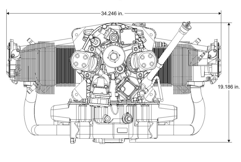
41 I PROCEDURES Figure 2-1. Dimensions 30
42 I PROCEDURES Figure 2-2. Installation, Left Side View 31

43 I PROCEDURES Figure 2-3. Installation, Rear View 32
44 I PROCEDURES 3. PRE-OILING ENGINE PRIOR TO START. CAUTION To eliminate the possibility of high-speed bearing failure resulting from insufficient lubrication during initial starts, all aircraft engines must be pre-oiled after an overhaul, following oil cooler draining or replacement, or whenever the oil lines have been disconnected. WARNING If a propeller is installed, remain clear of the propeller turning arc. The propeller will turn during this procedure, and could cause injury. a. Fill the oil cooler with oil. b. Remove one spark plug from each cylinder of the engine. c. If the aircraft is not equipped with an oil pressure gage, remove the STD-1102 allen plug from the upper left front of the main galley, aft of the propeller governor pad. d. Place the mixture control lever in the IDLE CUT-OFF position and the fuel selector switch in the OFF position. e. Turn the engine with the starter (or with an external power source, if available) until a minimum oil pressure of 20 lb. is indicated on the oil pressure gage or until there is a steady flow of oil from the opening on the engine. CAUTION Do not energize the starter for periods longer than 15 seconds. Allow the starter to cool after each energizing period. Refer to the starter manufacturer s instruction manual for additional information. NOTE If oil pressure is not determined after the first cranking of 10 to 15 seconds, allow the starter to cool and repeat the cranking/starter cooling sequence until 20 lb. is indicated on the oil pressure gage or oil flow is observed. CAUTION If there is no indication of steady oil pressure after five attempts, the cause should be determined and fixed. 33
45 I PROCEDURES f. Turn the starter for an additional 10 seconds to verify that the oil pressure remains at least 20 lb. g. Reinstall the spark plugs and proceed with normal starting procedures immediately. Refer to Section I, Part 3. h. When the engine starts, observe the oil pressure gage. If there is no oil pressure indication, shut down the engine until cause is determined. i. Allow the engine to run for approximately 3 minutes at 1000 rpm. j. Shut down in accordance with Section I, Part 3, Step
IO 390 A Series Operation and Installation Manual
 IO 390 A Series Operation and Installation Manual August 2008 (Cover Revised June 2009) FAA Approved Part No. 60297 34 2008 652 Oliver Street Williamsport, PA 17701 IO 390 A Series Operation and Installation
Accident Prevention Program
 Accident Prevention Program Part I ENGINE OPERATION FOR PILOTS by Teledyne Continental Motors SAFE ENGINE OPERATION INCLUDES: Proper Pre-Flight Use the correct amount and grade of aviation gasoline. Never
IO-720 Series. Operator s Manual Lycoming. Approved by FAA. 4 th Edition Part No
 Operator s Manual Lycoming IO-720 Series Approved by FAA 4 th Edition Part No. 60297-19 652 Oliver Street Williamsport, PA. 17701 U.S.A. 570/323-6181 October 2006 IO-720 Series Operator s Manual Lycoming
TIO-540-AE2A Series. Operator s Manual Lycoming. Approved by FAA. 2nd Edition Part No
 Operator s Manual Lycoming Series Approved by FAA 2nd Edition Part No. 60297-27 652 Oliver Street Williamsport, PA. 17701 U.S.A. 570/323-6181 November 2006 Series Operator s Manual Lycoming Part Number:
Operator s Manual Lycoming
 Operator s Manual Lycoming O-320 éê Series Approved by FAA 2nd Edition Part No. 60297-22 652 Oliver Street Williamsport, PA. 17701 U.S.A. 570/323-6181 April 2007 O-320 éê Series Operator s Manual Lycoming
O-540, IO-540 Series
 Operator s Manual Lycoming O-540, IO-540 Series Approved by FAA 4 th Edition Part No. 60297-10 652 Oliver Street Williamsport, PA. 17701 U.S.A. 570/323-6181 June 2006 O-540, IO-540 Series Operator s Manual
NOTE. In order to accommodate clearer type, larger charts and graphs, and more
 NOTE In order to accommodate clearer type, larger charts and graphs, and more detailed illustrations, this edition of the O-360, HO-360, IO-360, AIO-360, HIO-360 and TIO-360 Operator s Manual, Lycoming
Operators Manual Lycoming
 Operators Manual Lycoming TIO-541 Series Approved by FAA 3rd Edition Part No. 60297-13 652 Oliver Street Williamsport, PA. 17701 U.S.A. 570/323-6181 December 2007 TIO-541 Series Operators Manual Lycoming
Operation Reference Manual. Lycoming IO-390 SERIES. Part No Oliver Street Williamsport, PA U.S.A.
 Operation Reference Manual Lycoming Part No. 60297-29 652 Oliver Street Williamsport, PA. 17701 U.S.A. 570/323-6181 IO-390 Operation Reference Manual Lycoming Part Number: 60297-29 2007 by Lycoming. All
O-540-A4B5 PARTS CATALOG WIDE CYLINDER FLANGE CRANKCASE MODEL ENGINES
 INTRODUCTION This illustrated parts catalog contains a complete parts listing for the Lycoming O-540-A4B5 wide cylinder flange crankcase model aircraft engines. Major assembly and sub-assembly parts of
OPERATING RECOMMENDATIONS
 Operating Recommendations for TIO-540-AE2A Engine in Piper Aircraft Malibu Mirage Lycoming Part Number: SSP-400 OPERATING RECOMMENDATIONS FOR TIO-540-AE2A ENGINE IN PIPER AIRCRAFT MALIBU MIRAGE 2009 by
Copyright 2015 Airmotive Engineering Corp.
 Copyright 2015 Airmotive Engineering Corp. All rights reserved. Permission to reproduce or transmit in any form or by any means, electronic or mechanical, including photocopying and recording, or by any
Lycoming AIRCRAFT ENGINES. IO-540-AC1A5 Wide Series Flange Crankcase Model Engine PARTS CATALOG PC
 AIRCRAFT ENGINES IO-540-ACA5 Wide Series Flange Crankcase Model Engine PARTS CATALOG PC-5- November 008 Lycoming 5 Oliver Street Williamsport, PA 770 U.S.A. 570/33-8 IO-540-ACA5 PARTS CATALOG This illustrated
DAP-625S and DAP-875S
 AIR CHAMP PRODUCTS DAP-625S and DAP-875S (i) FORM NO. L-20078-B-0501 In accordance with Nexen s established policy of constant product improvement, the specifications contained in this manual are subject
IO-360, AIO-360, HIO-360 & TIO-360 Series
 Operator s Manual Lycoming O-360, HO-360, IO-360, AIO-360, HIO-360 & TIO-360 Series Approved by FAA 8 th Edition Part No. 60297-12 652 Oliver Street Williamsport, PA. 17701 U.S.A. 570/323-6181 October
DEPARTMENT OF TRANSPORTATION FEDERAL AVIATION ADMINISTRATION TYPE CERTIFICATE DATA SHEET NO. 1E12
 DEPARTMENT OF TRANSPORTATION FEDERAL AVIATION ADMINISTRATION TYPE CERTIFICATE DATA SHEET NO. 1E12 1E12 Revision 9 Lycoming Engines IO-320 -A1A-A2A-B1A, -B1B, B1C, -B1E, -B1D, -B2A, -C1A, -C1B, -D1A, -D1C,
HR-20P Pneumatically Controlled Pressure Regulator
 HR-20P Pneumatically Controlled Pressure Regulator Instruction and Service Manual Hydroplex Corporation 230 West Gloria Switch Rd. Lafayette, LA 70507 337-233-0626 www.hydroplexpumps.com I. General Instructions
OPERATOR'S MANUAL REVISION
 OPERATOR'S MANUAL REVISION REVISION NO. PUBLICATION PUBLICATION PUBLICATION NO. DATE TIO-540-AE2A 60297-27-2 Operator's Manual 60297-27 September 1988 The page(s) in this revision replace, add to, or delete
Frequently Asked Questions Certification 1. Are the ACS-320, ACS-360 and ACS-361 (ACS) Engines new zero time engines?
 Engines new zero time engines?") Frequently Asked Questions Certification 1. Are the ACS-320, ACS-360 and ACS-361 (ACS) Engines new zero time engines? Yes. The ACS Engines are brand new, zero time engines designed to meet the increasing
Frequently Asked Questions Certification 1. Are the ACS-320, ACS-360 and ACS-361 (ACS) Engines new zero time engines? Yes. The ACS Engines are brand new, zero time engines designed to meet the increasing
Single-Position Detent Clutch DC Series. (i) MTY (81) MEX (55) QRO (442)
 MTY (81) MEX (55) QRO (442)") Single-Position Detent Clutch DC Series (i) FORM NO. L-2017-A-001 In accordance with Nexen s established policy of constant product improvement, the specifications contained in this manual are subject
Single-Position Detent Clutch DC Series (i) FORM NO. L-2017-A-001 In accordance with Nexen s established policy of constant product improvement, the specifications contained in this manual are subject
Lycoming Aircraft Engines Parts Catalog
 Aircraft Engines Parts Catalog IO-0-BG Wide Cylinder Flange Crankcase Model Engine Part No. PC-0- Oliver Street Williamsport, PA 770 Aircraft Engines Parts Catalog IO-0-BG Wide Cylinder Flange Crankcase
2003 Lycoming. All rights reserved. Lycoming and "Powered by Lycoming" are trademarks or registered trademarks of Lycoming.
 O-50-AD5 Engine Parts Catalog Lycoming Part Number: PC-55-3 003 Lycoming. All rights reserved. Lycoming and "Powered by Lycoming" are trademarks or registered trademarks of Lycoming. All brand and product
LYCOMING A Textron Company
 LYCOMING AEIO-360-HB PARTS CATALOG This illustrated parts catalog contains a complete parts listing for the Lycoming AEIO-360-HB wide cylinder flange crankcase model aircraft engines. Major assembly and
Installation Instructions
 85-3910 rev. 03 01-18 Installation Instructions Thank you for purchasing the antisway bar kit. Please read through these instructions before installation. Rear Anti-Sway Bar Kit for Ford F-250/F-350 part
NECO Pumping Systems
 INSTALLATION OPERATION & MAINTENANCE INSTRUCTIONS For Your NECO Pumping Systems Fuel Oil Transfer System THIS COMPLETELY ASSEMBLED, TESTED, PACKAGED SYSTEM IS OF THE HIGHEST QUALITY AND DESIGN. TO OBTAIN
SECTION 4 PERIODIC INSPECTIONS NOTE
 LYCOMING OPERATOR S MANUAL SECTION 4 O-360 AND ASSOCIATED MODELS PERIODIC INSPECTIONS SECTION 4 PERIODIC INSPECTIONS NOTE Perhaps no other factor is quite so important to safety and durability of the aircraft
IO-540-AE1A5 Series Illustrated Parts Catalog
 IO-540-AE1A5 Series Illustrated Parts Catalog PC-615-AE1A5 (Replaces PC-615-13) 2013 652 Oliver Street Williamsport, PA 17701 IO-540-AE1A5 Series Illustrated Parts Catalog PC-615-AE1A5 (Replaces PC-615-13)
Installation Instructions
 85-4592 rev. 08 02-18 Installation Instructions Thank you for purchasing our sway bar kit. Please read through these instructions before installation. Auxiliary Rear Anti-Sway Bar Kit for Ford F53 part
O-540-F1B5 SERIES PARTS CATALOG WIDE CYLINDER FLANGE CRANKCASE MODEL ENGINES
 INTRODUCTION This illustrated parts catalog contains a complete parts listing for the Lycoming O-540-F1B5 series wide cylinder flange crankcase model aircraft engines. Major assembly and sub-assembly parts
TEXTRON Lycoming AIRCRAFT ENGINES
 TEXTRON Lycoming AIRCRAFT ENGINES O-60-AP Wide Cylinder Flange Crankcase Model Engines PARTS CATALOG PC-06-6 MARCH 99 0-60-AP PARTS CATALOG This illustrated parts catalog contains a complete parts listing
Installation Instructions
 85-3195 rev. 12 04-18 Installation Instructions Thank you for purchasing this antisway bar kit. Please read through these instructions before installation. Part #1139-117 Rear Anti-Sway Bar Kit 1½ diameter
Service Instruction ENGINE COMPONENTS, INC.
 Title: Service Instruction S.I. No.: 89-5-1 Page: 1 of 5 Issued: 05/05/89 Revision: 1 (09/01/01) Technical Portions of FAA DER Approved. FAILURE OF ENGINE TO START 27 points 1. Lack of fuel 2. Ignition
O-320-H 76 Series Illustrated Parts Catalog
 O-320-H 76 Series Illustrated Parts Catalog PC-122-H 76 Series 2013 652 Oliver Street Williamsport, PA 17701 O-320-H 76 Series Illustrated Parts Catalog PC-122-H 76 Series 2013 652 Oliver Street Williamsport,
37SCENE 46SCENE 79SCENE
 Installation and Operation Instructions LED SCENE LIGHT LED SCENE LIGHT 37SCENE 46SCENE 79SCENE 37SCENE 46SCENE Introduction The 37SCENE, 46SCENE, 79SCENE LED Scene Lights are designed for the emergency
DEPARTMENT OF TRANSPORTATION FEDERAL AVIATION ADMINISTRATION TYPE CERTIFICATE DATA SHEET NO. E-223
 DEPARTMENT OF TRANSPORTATION FEDERAL AVIATION ADMINISTRATION E-223 Revision 18 Textron Lycoming O-233-A1,O-235 O-235-A,-B,-AP,-BP-C,-C1,-C1A,-C1B,-C1C,-C2A,-C2B,-C2C, -E1,-E1B,-E2A,-E2B,-F1,-F1B,-F2A,-F2B,-G1,-G1B,-G2A,-G2B,
CIRRUS AIRPLANE MAINTENANCE MANUAL
 POWER PLANT 1. GENERAL This chapter describes maintenance practices for the airplane systems which provide the means to induce and convert fuel-air mixture into power such as the engine, baffling, cowling,
O-360-A4N Series Illustrated Parts Catalog
 O-360-A4N Series Illustrated Parts Catalog May 2011 PC-306-3 2011 652 Oliver Street Williamsport, PA 17701 Lycoming Part Number: PC-306-3 2011 by Avco Corporation. All Rights Reserved. Lycoming and Powered
European Aviation Safety Agency
 European Aviation Safety Agency EASA TYPE-CERTIFICATE DATA SHEET Number : IM.E.027 Issue : 02 Date : 06 May 2008 Type : Lycoming IO-580 series engines Variants Lycoming IO-580-B1A Lycoming AEIO-580-B1A
Installation Instructions
 85-4209 rev. 05 11-18 Installation Instructions Thank you for purchasing this anti-sway bar kit. Please read through these instructions before installation. Factory Replacement Anti-Sway Bar Kit part #1129-135
MetroPrime 22MPC Self-Priming Centrifugal Pump
 Page 1 of 6 prevent priming or reduce pump capacity. OPERATION The 22 MPC-Metropolitan Pump is a self-priming centrifugal pump and only requires priming prior to its initial start. The pump will retain
PUBLICATION REVISION
 Lycomlng 65 Oliver Street Williamsport, PA 770 U.S.A. 77/-6 TECHNICAL PUBLICATION REVISION REVISIOI No. PUBLICATION PUBLICATION No. PUBLICATION DATE IO-60-LA PC-06-A Engines PC-06- MAY, 996 This page(s)
Installation Instructions
 85-3700 rev. 08 05-18 Installation Instructions Thank you for purchasing this antisway bar kit. Please read through these instructions before installation. Front Anti-Sway Bar Kit for the F53 Chassis part
MEX (55) QRO (442) Web Controls
 QRO (442) Web Controls") Web Controls SINGLE AND DUAL ROTOR TENSION CONTROL BRAKES MODELS:,,,, AND INSTALLATION, OPERATION, AND MAINTENANCE INSTRUCTIONS Read this manual carefully, making full use of its explanations and instructions.
Web Controls SINGLE AND DUAL ROTOR TENSION CONTROL BRAKES MODELS:,,,, AND INSTALLATION, OPERATION, AND MAINTENANCE INSTRUCTIONS Read this manual carefully, making full use of its explanations and instructions.
Installation Instructions
 85-4341 rev. 04 10-15 Installation Instructions Thank you for purchasing this antisway bar kit. Please read through these instructions before installation. Rear Anti-Sway Bar Kit for Chevy 2500/3500/4500
INSTRUCTIONS AND SERVICE MANUAL WITH PARTS LIST
 CMP SERIES CPM15-15B (25905F300) CPM15-15B-H/D (25905F301) CPM18-15B (25905F303) CPM18-15B-H/D (25905F304) INDUSTRIAL PUMPS INSTRUCTIONS AND SERVICE MANUAL WITH PARTS LIST NOTE! To the installer: Please
FCB-450, LCB-600, MCB-800
 AIR CHAMP PRODUCTS User Manual FCB-450, LCB-600, MCB-800 Clutch-Brakes (i) In accordance with Nexen s established policy of constant product improvement, the specifications contained in this manual are
Installation Instructions
 85-5029 rev. 03 06-17 Installation Instructions Thank you for purchasing our anti-sway bar kit. Please read through these instructions before installation. Rear Anti-Sway Bar Kit for Workhorse W22, Holiday
Chapter 2. ENGINE DESCRIPTION CONTENTS. Chapter 2. Engine Description General Engine Description...2-3
 Teledyne Continental Motors, Inc. Chapter 2. ENGINE DESCRIPTION CONTENTS Chapter 2....2-1 2-1. General...2-3 2-1.1. Engine Model Number Definition... 2-5 2-1.2. Cylinder Number Designations... 2-5 2-2.
60 PSI Boost Gauge. For Product Numbers: MT-DV01_60, MT-WDV01_60
 60 PSI Boost Gauge For Product Numbers: MT-DV01_60, MT-WDV01_60 Red: 12v Constant (un-switched) Source (+) Orange: 12v Dimmer (switched) Source (+) (optional) White: 12v Ignition (switched) Source (+)
DeZURIK AFR3 Filter Regulator Used on Pneumatic Cylinder Actuators
 AFR3 Filter Regulator Used on Pneumatic Cylinder Actuators Instructions D11033 August 2013 Instructions These instructions provide information about AFR3 Filter Regulators. They are for use by personnel
MANUAL OPERATOR'S REVISION Island Enterprises. 80 Operators Manual. are intended either to replace, add to, or delete
 OPERATOR'S REVISION MANUAL REVISION No. PUBLICATION PUBLICATION No. PUBLICATION DATE 60297-14-2 60297-14-2 GO, IGO, GSO, IGSO- 60297-14 July, 1973 80 Operators Manual The page(s) furnishedherewith pages
Installation Instructions
 85-3214 rev. 07 03-11 Installation Instructions Thank you for purchasing this anti-sway bar kit. Please read through these instructions before installation. Rear Anti-Sway Bar Kit Freightliner FL Series
IO 360 M1B Series Illustrated Parts Catalog
 IO 360 M1B Series Illustrated Parts Catalog January 2011 PC 306 16 2011 652 Oliver Street Williamsport, PA 17701 Lycoming Part Number: PC 306 16 2011 by Avco Corporation. All Rights Reserved. Lycoming
European Aviation Safety Agency
 European Aviation Safety Agency EASA TYPE-CERTIFICATE DATA SHEET Number: IM.E.032 Issue: 01 Date: 27 September 2012 Type: Lycoming Engines Models IO-360-A1A IO-360-C1B AEIO-360-A1E6 HIO-360-F1AD IO-360-A1B
Lycoming Aircraft Engines Parts Catalog
 Lycoming Aircraft Engines Parts Catalog TIO-360-CA6D Wide Cylinder Flange Models Part No. PC-06-3 65 Oliver Street Williamsport, PA 770 Lycoming Aircraft Engines Parts Catalog TIO-360-CA6D Wide Cylinder
Do not install and/or operate this safety product unless you have read and understand the safety information contained in this manual.
 Installation and Operation Instructions MR Tri- Light Available in various color combinations, the MR Directional LED surface mount, tri-color warning light is ideal for a wide variety of auxiliary warning
INSTRUCTIONS SMOKE BLOWER WITH HONDA ENGINE PART NUMBER
 1 INSTRUCTIONS SMOKE BLOWER WITH HONDA ENGINE PART NUMBER 303-568 CHERNE INDUSTRIES INCORPORATED 1-800-THE PLUG 5700 LINCOLN DRIVE (1-800-843-7584) MINNEAPOLIS, MN 55436-1695 FAX: 1-800-843-7585 www.cherneind.com
REMOVAL AND INSTALLATION LABOR ALLOWANCE GUIDEBOOK FOR RECIPROCATING AIRCRAFT ENGINES
 REMOVAL AND INSTALLATION LABOR ALLOWANCE GUIDEBOOK FOR RECIPROCATING AIRCRAFT ENGINES SSP-875 Revision May 2000 2000 by Textron Lycoming All Rights Reserved -INTRODUCTION- The labor hours shown in this
TIO-540-AJ1A Illustrated Parts Catalog
 TIO-540-AJ1A Illustrated Parts Catalog May 2016 PC-TIO-540-AJ1A (Supersedes PC-315-12) 2016 652 Oliver Street Williamsport, PA 17701 Lycoming Part Number: PC-TIO-540-AJ1A (Supersedes PC-315-12) For additional
O-320-E2G Series Illustrated Parts Catalog
 O-320-E2G Series Illustrated Parts Catalog December 2011 PC-203-7 2011 652 Oliver Street Williamsport, PA 17701 O-320-E2G Illustrated Parts Catalog Lycoming Part Number: PC-203-7 2011 by Avco Corporation.
Lycoming Aircraft Engines Parts Catalog
 Lycoming Aircraft Engines Parts Catalog 76 Series O-360, LO-360 Series Part No. PC-3 65 Oliver Street Williamsport, PA 770 Lycoming Aircraft Engines Parts Catalog 76 Series O-360, LO-360 Series Part No.
WARRANTY POLICY. Grid-Tied Photovoltaic Inverters. Revision D. 2014, Solectria Renewables, LLC DOCIN
 WARRANTY POLICY Revision D 2014, Solectria Renewables, LLC DOCIN-070360 1 Product Warranty & RMA Policy 1. Warranty Policy Warranty Registration: It is important to have updated information about the inverter
Installation Instructions
 85-3207 rev. 03 05-06 Installation Instructions Thank you for purchasing this anti-sway bar kit. Please read through these instructions before installation. Rear Anti-Sway Bar Kit for the Freightliner
PMD DRIVER RELOCATION KIT For Chevy 6.5L Diesel Trucks
 - 1 - PMD DRIVER RELOCATION KIT For 1994-1999 Chevy 6.5L Diesel Trucks Part# 1036520 -- Installation Instructions -- PLEASE READ ALL INSTRUCTIONS CAREFULLY BEFORE INSTALLATION. - 2 - Kit Contents BD P/N#
Installation Instructions
 85-3511 rev. 04 11-15 Installation Instructions Polyurethane Bushing Kit for Ford F-53 (Front) (replaces OE bushings and brackets) part #4139-127 1-5/8 diameter INTRODUCTION Thank you for purchasing this
CARBURETOR REBUILD KIT (Vacuum Secondary) Models Demon Carburetors & Holley Model 4160 LIT704
 Models Demon Carburetors & Holley Model 4160 LIT704") CARBURETOR REBUILD KIT 190000 (Vacuum Secondary) Models Demon Carburetors & Holley Model 4160 LIT704 INSTRUCTIONS: Before getting to the actual rebuild, it should be noted that the carbs shown here are
CARBURETOR REBUILD KIT 190000 (Vacuum Secondary) Models Demon Carburetors & Holley Model 4160 LIT704 INSTRUCTIONS: Before getting to the actual rebuild, it should be noted that the carbs shown here are
SECTION D Engine 6.0L Diesel
 303-01D-i Engine 6.0L Diesel 303-01D-i SECTION 303-01D Engine 6.0L Diesel CONTENTS PAGE DESCRIPTION AND OPERATION Engine... 303-01D-2 303-01D-2 Engine 6.0L Diesel 303-01D-2 DESCRIPTION AND OPERATION Engine
INSTALLATION AND DETAIL SPECIFICATIONS FOR THE SILVER HAWK TM EX-5VA1 TM SERVO KIT
 INSTALLATION AND DETAIL SPECIFICATIONS FOR THE SILVER HAWK TM EX-5VA1 TM SERVO KIT 25-020_C.DOC 2-23-2015 Precision Airmotive LLC fuel systems are produced using the highest quality materials and components.
MULTIPOSITION AIR CYLINDER
 MULTIPOSITION AIR CYLINDER CAST ALUMINUM FOUR-POSITION - ALL AIR SERVICE INFORMATION MOUNTING! Devices should be mounted and positioned in such a manner that they cannot be accidentally operated. INSTALLATION
IO-360, AIO-360, HIO-360 & TIO-360 Series
 Operator s Manual Lycoming O-360, HO-360, IO-360, AIO-360, HIO-360 & TIO-360 Series Approved by FAA 8 th Edition Part No. 60297-12 652 Oliver Street Williamsport, PA. 17701 U.S.A. 570/323-6181 October
O 540 A4E5 Series Illustrated Parts Catalog
 O 540 A4E5 Series Illustrated Parts Catalog April 2012 PC 515 A4E5 2012 652 Oliver Street Williamsport, PA 17701 Lycoming Part Number: PC 515 A4E5 2012 by Avco Corporation. All Rights Reserved. Lycoming
Installation Instructions
 85-3209 rev. 07 03-11 Installation Instructions Thank you for purchasing this anti-sway bar kit. Please read through these instructions before installation. Front Anti-Sway Bar Kit for Workhorse W22, Holiday
Owner s Manual Supplement. Liquefied Petroleum Gas (LPG) Fuel System for 1998 GM Medium Duty Chassis (C-60/C-70) with 6.0L and 7.
 Fuel System for 1998 GM Medium Duty Chassis (C-60/C-70) with 6.0L and 7.") Owner s Manual Supplement Liquefied Petroleum Gas (LPG) Fuel System for 1998 GM Medium Duty Chassis (C-60/C-70) with 6.0L and 7.0L V8 OWNERS MANUAL SUPPLEMENT Table of Contents Refueling Your Vehicle...1
Owner s Manual Supplement Liquefied Petroleum Gas (LPG) Fuel System for 1998 GM Medium Duty Chassis (C-60/C-70) with 6.0L and 7.0L V8 OWNERS MANUAL SUPPLEMENT Table of Contents Refueling Your Vehicle...1
TYPE-CERTIFICATE DATA SHEET
 TYPE-CERTIFICATE DATA SHEET For Models: IO-390-A1A6 IO-390-A3A6 IO-390-A1B6 IO-390-A3B6 AEIO-390-A1A6 AEIO-390-A3A6 AEIO-390-A1B6 AEIO-390-A3B6 IO-390-C1A6 IO-390-C3A6 IO-390-C1B6 IO-390-C3B6 No. IM.E.097
 Page 1 of 9 303-01C Engine 6.0L Diesel 2004 F-Super Duty 250-550/Excursion DESCRIPTION AND OPERATION Procedure revision date: 08/06/2003 Engine Printable View Engine Description The 6.0L diesel engine
DeZURIK 2 20" BOS BUTTERFLY VALVES
 2 20" BOS BUTTERFLY VALVES Instruction D10459 October 2013 2-20 BOS Butterfly Valves Instructions These instructions provide information about BOS Butterfly Valves. They are for use by personnel who are
Installation Instructions
 85-3414 rev. 02 11-09 Installation Instructions Thank you for purchasing this anti-sway bar kit. Please read through these instructions before installation. Rear Anti-Sway Bar Kit for the Monaco Diplomat
PENBERTHY MODELS GL AND GH GAS OPERATED JET PUMPS INSTALLATION, OPERATION AND MAINTENANCE INSTRUCTIONS
 Before installation, these instructions must be read carefully and understood. PRODUCT WARRANTY Emerson warrants its Penberthy products as designed and manufactured to be free of defects in the material
O-360-C1G Series Illustrated Parts Catalog
 O-360-C1G Series Illustrated Parts Catalog April 2011 PC-306-4 2011 652 Oliver Street Williamsport, PA 17701 Lycoming Part Number: PC-306-4 2011 by Avco Corporation. All Rights Reserved. Lycoming and Powered
Installation Instructions
 85-3909 rev. 01 09-09 Installation Instructions Thank you for purchasing this anti-sway bar kit. Please read through these instructions before installation. Rear Anti-Sway Bar Kit for Chevrolet G30 part
********NOTICE********
 IO-540-K1A5 Series Illustrated Parts Catalog February 2015 ********NOTICE******** This parts catalog, PC-615-K1A5 Series (models IO-540-K1A5, IO-540-K1A5D) supersedes the previous IO-540-K1A5, IO-540-K1A5D
APCO ASR-400/450 SEWAGE AIR RELEASE VALVES
 APCO ASR-400/450 SEWAGE AIR RELEASE VALVES Instruction D12005 December 2012 Instructions These instructions provide installation, operation and maintenance information for the APCO ASR- 400/450 Sewage
EMISSION CONTROL WARRANTY STATEMENT
 EMISSION CONTROL WARRANTY STATEMENT YOUR WARRANTY RIGHTS AND OBLIGATIONS The California Air Resources Board, U.S. EPA and Zenith Power Products LLC (ZPP) are pleased to explain the emission control system
Warranty Information North America
 Publication No. 47705137 January 1, 2014 Warranty Information North America Industrial and Power Generation Power Systems Parts and Accessories Includes: Power Systems Warranty Statement Parts and Accessories
DEPARTMENT OF TRANSPORTATION FEDERAL AVIATION ADMINISTRATION
 DEPARTMENT OF TRANSPORTATION FEDERAL AVIATION ADMINISTRATION 1E10 Revision No. 22 TEXTRON Lycoming IO-360-A1A, -A1B, -A1B6, -A1B6D, -A1C, -A1D, -A1D6, -A1D6D, -A2A, -A2B, -A2C, -A3B6,-A3B6D, -A3D6D, -B1A,
IO-540-K1H5 Series Illustrated Parts Catalog
 IO-50-KH5 Series Illustrated Parts Catalog November 983 Engine model IO-50-KK5, previously covered in this parts catalog, has been superseded by PC-5-KK5. PC-5-03 5 Oliver Street Williamsport, PA 770 IO-50-KH5
O-320-A2C, -A2D Series Illustrated Parts Catalog
 O-320-A2C, -A2D Series Illustrated Parts Catalog September 2011 PC-203-2 2011 652 Oliver Street Williamsport, PA 17701 O-320-A2C, -A2D Illustrated Parts Catalog Lycoming Part Number: PC-203-2 2011 by Avco
TONS. Before each shift: Before operating: Before initial operation of hoist:
 LEVER HOIST 0.25 9 TONS Manual Notice It is the responsibility of the owner/user to install, inspect, test, maintain, and operate these lever hoists in accordance with ASME B30.21, Safety Standard for
Installation Instructions
 85-3180 rev. 07 03-14 Installation Instructions Thank you for purchasing this antisway bar kit. Please read through these instructions before installation. Front Anti-Sway Bar Kit for the Ford E350/450
Elgin Hydraulic Clutch-Brake ECB-240, Product Number FORM NO. L F FORM NO. L F-0704
 Elgin Hydraulic Clutch-Brake ECB-20, Product Number 96225 FORM NO. L-20283-F-070 1 FORM NO. L-20283-F-070 In accordance with Nexen s established policy of constant product improvement, the specifications
PVI 60KW, PVI 82KW, PVI 95KW
 PVI 60KW PVI 82KW PVI 95KW WARRANTY MANUAL Commercial, Grid-Tied Photovoltaic Inverters 2008, Solectria Renewables LLC Subject to Change DOC-020099 rev 024 1 1 Product Warranty & RMA Policy Warranty Policy
Installation Instructions
 85-3847 rev. 01 09-09 Installation Instructions Thank you for purchasing this anti-sway bar kit. Please read through these instructions before installation. Front Anti-Sway Bar TruTrac Bar Combo Kit for
NECO Pumping Systems
 INSTALLATION OPERATION & MAINTENANCE INSTRUCTIONS For Your NECO Pumping Systems PACKAGED CIRCULATING SYSTEM THIS COMPLETELY ASSEMBLED, TESTED, PACKAGED CIRCULATING SYSTEM IS OF THE HIGHEST QUALITY AND
Submersible Pond Pump with UV 800 Gallons Per Hour
 Submersible Pond Pump with UV 800 Gallons Per Hour REMINDER CALL 1-888-755-6750 BEFORE RETURNING TO STORE. PACKAGE CONTENTS ITEM #PP800UV Questions, problems, missing parts? Before returning to your retailer,
Mechanical Filter Box Kit
 Mechanical Filter Box Kit REMINDER CALL 1-888-755-4497 BEFORE RETURNING TO STORE. MODEL #MFBX500P Questions, problems, missing parts? Before returning to your retailer, call our customer service department
CARENADO COPYRIGHTS. Normal & Emergency Checklist
 NORMAL PROCEDURES CHECKLIST PREFLIGHT CHECK Control wheel -- RELEASE BELTS Avionics -- OFF Master Switch -- ON Fuel quantity gauges -- CHECK Master switch -- OFF Ignition -- OFF Exterior -- CHECK FOR DAMAGE
Straight-Bore Clutch LSCC-32, 44, 54
 Straight-Bore Clutch LSCC-32, 44, 54 1 In accordance with Nexen s established policy of constant product improvement, the specifications contained in this manual are subject to change without notice. Technical
Owner s Manual GLASSLINED PUMP TANK
 Owner s Manual GLASSLINED PUMP TANK ANSI/NSF 61 Annex G Thank You for purchasing a pump tank. Properly installed and maintained, it should give you years of trouble free service. If you should decide that
TEXTRON Lycoming AIRCRAFT ENGINES
 TEXTRON Lycoming AIRCRAFT ENGINES O-60-CF & -CP Wide Cylinder Flange Crankcase Model Engines PARTS CATALOG PC-06- OCTOBER 995 65 Oliver Street Williamsport, PA 770 U.S.A. 77/-6 Lycoming O-60-CF &-CP PARTS
Open Display Merchandiser Installation and Operation Manual Please read this manual completely before attempting to install or operate this equipment!
 Turbo Air Speed up the Pace of Innovation CAUTION! PLEASE KEEP POWER SWITCH ON BEFORE OPERATING THIS EQUIPMENT Open Display Merchandiser Installation and Operation Manual Please read this manual completely