NOTE. In order to accommodate clearer type, larger charts and graphs, and more
|
|
|
- Milton Black
- 5 years ago
- Views:
Transcription
1 NOTE In order to accommodate clearer type, larger charts and graphs, and more detailed illustrations, this edition of the O-360, HO-360, IO-360, AIO-360, HIO-360 and TIO-360 Operator s Manual, Lycoming Part Number , is presented in an 8-1/2 x 11 inch format. This edition is a complete manual, current as of the date of issue. The manual incorporates all previously issued revisions. This manual will be kept current by revisions available from Lycoming distributors or from the factory. All revisions will be accompanied by an Operator s Manual Revision page which will identify the revision level, the date of the revision, and the pages revised, added or deleted. All revisions will be supplied in the 8-1/2 x 11 inch format.
2 Operator s Manual Lycoming O-360, HO-360, IO-360, AIO-360, HIO-360 & TIO-360 Series Approved by FAA 8 th Edition Part No Oliver Street Williamsport, PA U.S.A. 570/ October 2005
3 OPERATORS MANUAL REVISION REVISION NO. PUBLICATION PUBLICATION NO. PUBLICATION DATE O-360, HO-360, IO-360, AIO-360, HIO-360 & TIO-360 Series October 2005 The page(s) in this revision replace, add to, or delete current pages in the operators manual. PREVIOUS REVISION CURRENT REVISION June 2007 Web Page; 3-38 March ; Section 2 Index, 2-3, 2-8, 2-11; 3-5, 3-21, 3-41 September , 3-9, 3-11 December , by Lycoming All Rights Reserved Lycoming Engines, a division of AVCO Corporation, a wholly owned subsidiary of Textron Inc.
4 OPERATOR S MANUAL REVISION REVISION NO. PUBLICATION PUBLICATION NO. PUBLICATION DATE O-360, HO-360, IO-360, AIO-360, HIO-360 & TIO-360 Series October 2005 The page(s) in this revision replace, add to, or delete current pages in the operator s manual. PREVIOUS REVISION CURRENT REVISION June 2007 Web Page; 3-38 December , 3-5 September , 3-9, 3-11
5 OPERATOR S MANUAL REVISION REVISION NO. PUBLICATION PUBLICATION NO. PUBLICATION DATE O-360, HO-360, IO-360, AIO-360, HIO-360 & TIO-360 Series October 2005 The page(s) in this revision replace, add to, or delete current pages in the operator s manual. PREVIOUS REVISION CURRENT REVISION June 2007 Web Page; 3-38 September , 3-9, 3-11
6 OPERATOR S MANUAL REVISION REVISION NO. PUBLICATION PUBLICATION NO. PUBLICATION DATE O-360, HO-360, IO-360, AIO-360, HIO-360 & TIO-360 Series October 2005 The page(s) in this revision replace, add to, or delete current pages in the operator s manual. PREVIOUS REVISION CURRENT REVISION None June 2007 Web Page; 3-38
7 O, HO, IO, AIO, HIO, TIO-360 Series Operator s Manual Lycoming Part Number: by Lycoming. All rights reserved. Lycoming and Powered by Lycoming are trademarks or registered trademarks of Lycoming. All brand and product names referenced in this publication are trademarks or registered trademarks of their respective companies. For additional information: Mailing address: Lycoming Engines 652 Oliver Street Williamsport, PA U.S.A. Phone: Factory: Sales Department: Fax: Lycoming s regular business hours are Monday through Friday from 8:00 AM through 5:00 PM Eastern Time (-5 GMT) Visit us on the World Wide Web at: Revised June 2007
8 LYCOMING OPERATOR S MANUAL ATTENTION OWNERS, OPERATORS, AND MAINTENANCE PERSONNEL This operators manual contains a description of the engine, its specifications, and detailed information on how to operate and maintain it. Such maintenance procedures that may be required in conjunction with periodic inspections are also included. This manual is intended for use by owners, pilots and maintenance personnel responsible for care of Lycoming powered aircraft. Modifications and repair procedures are contained in Lycoming overhaul manuals; maintenance personnel should refer to these for such procedures. SAFETY WARNING NEGLECTING TO FOLLOW THE OPERATING INSTRUCTIONS AND TO CARRY OUT PERIODIC MAINTENANCE PROCEDURES CAN RESULT IN POOR ENGINE PERFORMANCE AND POWER LOSS. ALSO, IF POWER AND SPEED LIMITATIONS SPECIFIED IN THIS MANUAL ARE EXCEEDED, FOR ANY REASON; DAMAGE TO THE ENGINE AND PERSONAL INJURY CAN HAPPEN. CONSULT YOUR LOCAL FAA APPROVED MAINTENANCE FACILITY. SERVICE BULLETINS, INSTRUCTIONS, AND LETTERS Although the information contained in this manual is up-to-date at time of publication, users are urged to keep abreast of later information through Lycoming Service Bulletins, Instructions and Service Letters which are available from all Lycoming distributors or from the factory by subscription. Consult the latest revision of Service Letter No. L114 for subscription information. SPECIAL NOTE The illustrations, pictures and drawings shown in this publication are typical of the subject matter they portray; in no instance are they to be interpreted as examples of any specific engine, equipment or part thereof. iii
9 LYCOMING OPERATOR S MANUAL IMPORTANT SAFETY NOTICE Proper service and repair is essential to increase the safe, reliable operation of all aircraft engines. The service procedures recommended by Lycoming are effective methods for performing service operations. Some of these operations require the use of tools specially designed for the task. These special tools must be used when and as recommended. It is important to note that most Lycoming publications contain various Warnings and Cautions which must be carefully read in order to minimize the risk of personal injury or the use of improper service methods that may damage the engine or render it unsafe. It is also important to understand that these Warnings and Cautions are not all inclusive. Lycoming could not possibly know, evaluate or advise the service trade of all conceivable ways in which service might be done or of the possible hazardous consequences that may be involved. Accordingly, anyone who uses a service procedure must first satisfy themselves thoroughly that neither their safety nor aircraft safety will be jeopardized by the service procedure they select. iv
10 WARRANTY NEW AND REBUILT ENGINES (1) WARRANTY AND REMEDY: Lycoming Engines, a division of Avco Corporation (hereinafter Lycoming ) warrants each new Lycoming reciprocating engine to be free from defect in material or workmanship under normal use and service. Lycoming s sole obligation under this warranty is limited to replacement or repair of parts which are determined by Lycoming to have been defective within a period of twenty-four (24) months after new aircraft delivery to the original retail purchaser or first user, or twenty-four (24) months from the date of first operation. The warranty period of twenty-four (24) months commences on the earlier of the date of first operation after new aircraft delivery to the original retail purchaser or first user, or twenty-four (24) months from the date of shipment from Lycoming. Lycoming will, in connection with the foregoing warranty, cover reimbursement of reasonable freight charges with respect to any such warranty replacement or repair. (2) Within the warranty period, Lycoming will reimburse the Purchaser for labor charges associated with warranty related issues. Lycoming will only reimburse the cost of such labor charges in connection with repair or replacement of parts as provided in Lycoming s then current Removal and Installation Labor and Allowance Guidebook. Spare parts installed as warranty replacement on engines which are covered by this New Engine Warranty will be warranted for the balance of the original warranty period or for the spare part warranty, whichever is the greater. Replacement of parts may be with either new or reconditioned parts, at Lycoming s election. A claim for warranty on any part claimed to be defective must be reported in writing to Lycoming s Warranty Administration within 60 days of being found to require repair or replacement by the purchaser or service facility. Warranty adjustment is contingent upon the Purchaser complying with the Lycoming s Warranty Administration disposition instructions for defective parts. Failure to comply with all of the terms of this paragraph may, at Lycoming s sole option, void this warranty. (3) THIS WARRANTY IS GIVEN AND ACCEPTED IN PLACE OF (i) ALL OTHER WARRANTIES OR CONDITIONS, EXPRESS OR IMPLIED, INCLUDING BUT NOT LIMITED TO THE IMPLIED WARRANTIES OR CONDITION OF MERCHANTABILITY AND FITNESS FOR A PARTICULAR PURPOSE AND (ii) ANY OBLIGATION, LIABILITY, RIGHT, CLAIM OR REMEDY IN CONTRACT OR IN TORT (DELICT), INCLUDING PRODUCT LIABILITIES BASED UPON STRICT LIABILITY, NEGLIGENCE, OR IMPLIED WARRANTY IN LAW AND PURCHASER HEREBY WAIVES SUCH RIGHTS AND CLAIMS. (4) THIS WARRANTY IS THE ONLY WARRANTY MADE BY LYCOMING. THE PURCHASER S SOLE REMEDY FOR A BREACH OF THIS WARRANTY OR ANY DEFECT IN A PART IS THE REPAIR OR REPLACEMENT OF ENGINE PARTS AND REIMBURSEMENT OF REASONABLE FREIGHT CHARGES AS PROVIDED HEREIN. LYCOMING EXCLUDES LIABILITY, WHETHER AS A RESULT OF A BREACH OF CONSEQUENTIAL DAMAGES, INCLUDING, BUT NOT LIMITED TO, DAMAGE TO THE ENGINE OR OTHER PROPERTY (INCLUDING THE AIRCRAFT IN WHICH THE ENGINE IS INSTALLED), COSTS AND EXPENSES RESULTING FROM REQUIRED CHANGES OR MODIFICATIONS TO ENGINE COMPONENTS AND ASSEMBLIES, CHANGES IN RETIREMENT LIVES AND OVERHAUL PERIODS, LOCAL CUSTOMS FEES AND TAXES, AND COSTS OR EXPENSES FOR COMMERCIAL LOSSES OR LOST PROFITS DUE TO LOSS OF USE OR GROUNDING OF THE AIRCRAFT IN WHICH THE ENGINE IS INSTALLED OR OTHERWISE. LYCOMING S TOTAL LIABILITY FOR ANY AND ALL CLAIMS RELATED TO ANY ENGINE SHALL IN NO CASE EXCEED THE ORIGINAL SALES PRICE OF THE ENGINE. SELLER MAKES NO WARRANTY AND DISCLAIMS ALL LIABILITY WITH RESPECT TO COMPONENTS OR PARTS DAMAGED BY, OR WORN DUE TO, CORROSION.

11 (5) This warranty shall not apply to any engine or part thereof which has been repaired or altered outside Lycoming s factory in any way so as, in Lycoming s sole judgment, to affect its durability, safety or reliability, or which has been subject to misuse, negligence or accident. Repairs and alterations which use or incorporate parts and components other than genuine Lycoming parts or parts approved by Lycoming for direct acquisition from sources other than Lycoming itself are not warranted by Lycoming, and this warranty shall be void to the extent that such repairs and alterations, in Lycoming s sole judgment, affect the durability, safety or reliability of the engine or any part thereof, or damage genuine Lycoming or Lycoming-approved parts. No person, corporation or organization, including Distributors of Lycoming engines, is authorized by Lycoming to assume for it any other liability in connection with the sale of its engines or parts, nor to make any warranties beyond the foregoing warranty nor to change any of the terms hereof. NO STATEMENT, WHETHER WRITTEN OR ORAL, MADE BY ANY PERSON, CORPORATION OR ORGANIZATION, INCLUDING DISTRIBUTORS OF LYCOMING ENGINES MAY BE TAKEN AS A WARRANTY NOR WILL IT BIND LYCOMING. NO AGREEMENT VARYING THE TERMS OF THIS WARRANTY OR LYCOMING S OBLIGATIONS UNDER IT IS BINDING UPON LYCOMING UNLESS IN WRITING AND SIGNED BY A DULY AUTHORIZED REPRESENTATIVE OF LYCOMING. (6) All legal actions based upon claims or disputes pertaining to or involving this warranty including, but not limited to, Lycoming s denial of any claim or portion thereof under this warranty, must be filed in the courts of general jurisdiction of Lycoming County, Commonwealth of Pennsylvania or in the United States District Court for the Middle District of Pennsylvania located in Williamsport, Pennsylvania. In the event that Purchaser files such an action in either of the court systems identified above, and a final judgment in Lycoming s favor is rendered by such court, then Purchaser shall indemnify Lycoming for all costs, expenses and attorneys fee incurred by Lycoming in defense of such claims. In the event Purchaser files such a legal action in a court other than those specified, and Lycoming successfully obtains dismissal of that action or transfer thereof to the above described court systems, then Purchaser shall indemnify Lycoming for all costs, expenses and attorneys fees incurred by Lycoming in obtaining such dismissal or transfer. (7) Any invalidity of a provision of this Warranty shall not affect any other provision, and in the event of a judicial finding of such invalidity, this Agreement shall remain in force in all other respects. Effective September 2006 Revision M Ô ½±³ ²¹ Û²¹ ²» 652 Oliver Street Williamsport, Pennsylvania (570)
12 LYCOMING OPERATOR S MANUAL TABLE OF CONTENTS Page SECTION 1 DESCRIPTION 1-1 SECTION 2 SPECIFICATIONS 2-1 SECTION 3 OPERATING INSTRUCTIONS 3-1 SECTION 4 PERIODIC INSPECTIONS 4-1 SECTION 5 MAINTENANCE PROCEDURES 5-1 SECTION 6 TROUBLE-SHOOTING 6-1 SECTION 7 INSTALLATION AND STORAGE 7-1 SECTION 8 TABLES 8-1
13 This Page Intentionally Left Blank
14 LYCOMING OPERATOR S MANUAL SECTION 1 DESCRIPTION Page General Cylinders Valve Operating Mechanism Crankcase Crankshaft Connecting Rods Pistons Accessory Housing Oil Sump Cooling System Induction System Lubrication System Priming System Ignition System Counterweight System Model Application Table
15 This Page Intentionally Left Blank
16 LYCOMING OPERATOR S MANUAL SECTION 1 O-360 AND ASSOCIATED MODELS DESCRIPTION SECTION 1 DESCRIPTION The O. HO, IO, AIO, HIO, LIO and TIO-360 series are four cylinder, direct drive, horizontally opposed, air-cooled engines. In referring to the location of the various engine components, the parts are described as installed in the airframe. Thus, the power take-off end is the front and the accessory drive end the rear. The sump section is the bottom and the opposite side of the engine where the shroud tubes are located the top. Reference to the left and right side is made with the observer facing the rear of the engine. The cylinders are numbered from front to rear, odd numbers on the right. The direction of rotation of the crankshaft, viewed from the rear, is clockwise. Rotation for accessory drives is determined with the observer facing the drive pad. NOTE The letter L in the model prefix denotes the reverse rotation of the basic model. Example: model IO-360-C has clockwise rotation of the crankshaft. Therefore, LIO-360-C has counterclockwise rotation of the crankshaft. Likewise, the rotation of the accessory drives of the LIO-360-C is opposite those of the basic model as listed in Section 2 of this manual. The letter D used as the 4 th or 5 th character in the model suffix denotes that the particular model employs dual magnetos housed in a single housing. Example: All information pertinent to the O-360-A1F6 will apply to the O-360-A1F6D. Operational aspects of engines are the same and performance curves and specifications for the basic model will apply. Cylinders The cylinders are of conventional air-cooled construction with the two major parts, head and barrel, screwed and shrunk together. The heads are made from an aluminum alloy casting with a fully machined combustion chamber. Rocker shaft bearing supports are cast integral with the head along with housings to form the rocker boxes. The cylinder barrels have deep integral cooling fins and the inside of the barrels are ground and honed to a specified finish. Valve Operating Mechanism A conventional type camshaft is located above and parallel to the crankshaft. The camshaft actuates hydraulic tappets, which operate the valves through push rods and valve rockers. The valve rockers are supported on full floating steel shafts. The valve springs bear against hardened steel seats and are retained on the valve stems by means of split keys. Crankcase The crankcase assembly consists of two reinforced aluminum alloy castings, fastened together by means of studs, bolts and nuts. The mating surfaces of the two castings are joined without the use of a gasket, and the main bearing bores are machined for use of precision type main bearing inserts. Crankshaft The crankshaft is made from a chrome nickel molybdenum steel forging. All bearing journal surfaces are nitrided. 1-1
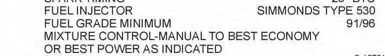
17 SECTION 1 DESCRIPTION LYCOMING OPERATOR S MANUAL O-360 AND ASSOCIATED MODELS Connecting Rods The connecting rods are made in the form of H sections from alloy steel forgings. They have replaceable bearing inserts in the crankshaft ends and bronze bushings in the piston ends. Two bolts and nuts through each cap retain the bearing caps on the crankshaft ends. Pistons The pistons are machined from an aluminum alloy. The piston pin is of a full floating type with a plug located in each end of the pin. Depending on the cylinder assembly, pistons may be machined for either three or four rings and may employ either half wedge or full wedge rings. Consult the latest revision of Service Instruction No for proper piston and ring combinations. Accessory Housing The accessory housing is made from an aluminum casting and is fastened to the rear of the crankcase and the top rear of the sump. If forms a housing for the oil pump and the various accessory drives. Oil Sump (Except AIO Series) The sump incorporates an oil drain plug, oil suction screen, mounting pad for carburetor or fuel injector, the intake riser and intake pipe connections. Crankcase Covers (AIO Series) Crankcase covers are employed on the top and bottom of the engine. These covers incorporate oil suction screens, oil scavenge line connections. The top cover incorporates a connection for a breather line and the lower cover a connection for an oil suction line. Cooling System These engines are designed to be cooled by air pressure. Baffles are provided to build up a pressure and force the air through the cylinder fins. The air is then exhausted to the atmosphere through gills or augmentor tubes usually located at the rear of the cowling. Induction System Lycoming O-360 and HO-360 series engines are equipped with either a float type or pressure type carburetor. See Table 1 for model application. Particularly good distribution of the fuel-air mixture to each cylinder is obtained through the center zone induction system, which is integral with the oil sump and is submerged in oil, insuring a more uniform vaporization of fuel and aiding in cooling the oil in the sump. From the riser the fuel-air mixture is distributed to each cylinder by individual intake pipes. Lycoming IO-360, AIO-360, HIO-360 and TIO-360 series engines are equipped with a Bendix type RSA fuel injector, with the exception of model IO-360-B1A that is equipped with a Simmonds type 530 fuel injector. (See Table 1 of model application.) The fuel injection system schedules fuel flow in proportion to air flow and fuel vaporization takes place at the intake ports. A turbocharger is mounted as an integral part of the TIO-360 series engines. Automatic waste gate control of the turbocharger provides constant air density to the fuel injector inlet from sea level to critical altitude. A brief description of the carburetors and fuel injectors follows: The Marvel-Schebler MA-4-5 and HA-6 carburetors are of the single barrel float type equipped with a manual mixture control and an idle cut-off. The Marvel-Schebler MA-4-5AA carburetor is of the single barrel float type with automatic pressure altitude mixture control. This carburetor is equipped with idle cut-off but does not have a manual mixture control. The Bendix-Stromberg PSH-5BD is a pressure operated, single barrel horizontal carburetor, incorporating an airflow operated power enrichment valve and an automatic mixture control unit. It is equipped with an idle cut-off and a manual mixture control. The AMC unit works independently of, and in parallel with, the manual mixture control. 1-2
18 LYCOMING OPERATOR S MANUAL SECTION 1 O-360 AND ASSOCIATED MODELS DESCRIPTION The Bendix RSA type fuel injection system is based on the principle of measuring air flow and using the air flow signal in a stem type regulator to convert the air force into a fuel force. This fuel force (fuel pressure differential) when applied across the fuel metering section (jetting system) makes fuel flow proportional to airflow. The Simmonds type 530 is a continuous flow fuel injection system. This continuous flow system has three separate components: 1. A fuel pump assembly. 2. A throttle body assembly. 3. Four fuel flow nozzles. This system is throttle actuated. Fuel is injected into the engine intake valve ports by the nozzles. The system continuously delivers metered fuel to each intake valve port in response to throttle position, engine speed and mixture control position. Complete flexibility of operation is provided by the manual mixture control, which permits the adjustment of the amount of injected fuel to suit all operating conditions. Moving the mixture control to Idle Cut-Off results in a complete cut-off of fuel to the engine. Lubrication System (All models except AIO-360 series). An impeller type pump contained within the accessory housing actuates the full pressure wet sump lubrication system. AIO-360 Series The AIO-360 series is designed for aerobatic flying and is of the dry sump type. A double scavenge pump is installed on the accessory housing. Priming System Provision for a primer system is provided on all engines employing a carburetor. Fuel injected engines do not require a priming system. Ignition System Dual ignition is furnished by two Bendix magnetos. Consult Table 1 for model application. Counterweight System Models designated by the numeral 6 in the suffix of the model number (Example: O-360-A1G6) are equipped with crankshafts with pendulum type counterweights attached. TABLE 1 MODEL APPLICATION Model Left** Right** Carburetor O-360 -A1A, -A2A, -A3A, -A4A -A1C, -C2D -A1D, -A2D, -A3D, -A4D, -A2E -A1F, -A2F, -A1F6 -A1G, -A2G, -A4G, -A1G6 -A1H, -A2H, -A4J -A1H6 -A1P, -A4P, -B2C, -C4P -A4K, -C1F, -C4F -A4M S4LN-21 S4LN-200 S4LN-200 S4LN-1227 S4LN-1227 S4LN S4LN-20 S4LN-204 S4LN-204 S4LN-1209 S4LN-1209 S4LN MA-4-5 PSH-5BD MA-4-5 MA-4-5 HA-6 HA-6 HA-6 MA-4-5 HA-6 MA-4-5 * - Models with counterclockwise rotation employ S4RN series. ** - See latest revision of Service Instruction No for alternate magnetos. 1-3
19 SECTION 1 DESCRIPTION LYCOMING OPERATOR S MANUAL O-360 AND ASSOCIATED MODELS TABLE 1 (CONT.) MODEL APPLICATION Model Left** Right** Carburetor O-360 (Cont.) -A4N -B1A, -B2A, -C1A, -C1G, -C2A -B1B, -B2B, -C1C, -C2C -C1E, -C2E, -A4M -C2B -D1A, -D2A -D2B -F1A6 -G1A6 -J2A O-360 Dual Magneto 4251 S4LN-21 S4LN S4LN-21 S4LN-21 S4LN S4LN-20 S4LN S4LN-20 S4LN-20 S4LN MA-4-5 MA-4-5 MA-4-5 MA-4-5 PSH-5BD MA-4-5 MA-4-5 HA-6 HA-6 MA-4SPA -A1AD, -A3AD, -A5AD -A1F6D, -A1LD -A1G6D HO-360 D4LN-3021 D4LN-3021 D4LN-3021 MA-4-5 MA-4-5 HA-6 -A1A -B1A -B1B -C1A HIO-360 S4LN-200 S4LN-200 S4LN S4LN-204 S4LN-204 S4LN MA-4-5AA PSH-5BD PSH-5BD HA-6 Fuel Injector -A1A, -B1A, -B1B -A1B, -C1A -C1B -D1A -G1A HIO-360 Dual Magneto S4LN-200 S4LN-200 S4LN-1208 S4LN S4LN-200 S4LN-204 S4LN-1209 S4LN RSA-5AB1 RSA-5AD1 RSA-5AD1 RSA-7AA1 RSA-5AD1 -E1AD -E1BD, -F1AD IO-360 D4LN-3021 D4LN-3200 RSA-5AB1 RSA-5AB1 -A1A, -A2A, -B1B, -B1C -A1B, -A2B, -A1B6 -A1C, -A2C, -C1B -A1D6, -B1E, -B2E -A3B6 S4LN-200 S4LN-1227 S4LN-1208 S4LN S4LN-204 S4LN-1209 S4LN-1209 S4LN RSA-5AD1 RSA-5AD1 RSA-5AD1 RSA-5AD1 RSA-5AD1 * - Models with counterclockwise rotation employ S4RN series. ** - See latest revision of Service Instruction No for alternate magnetos. 1-4
20 LYCOMING OPERATORS MANUAL SECTION 1 O-360 AND ASSOCIATED MODELS DESCRIPTION TABLE 1 (CONT.) MODEL APPLICATION Model Left** Right** Fuel Injector IO-360 (Cont.) -B1A -B1D, -C1A -B1F, -B2F, -B2F6 -B4A, -K2A -C1C, -C1C6, -C1D6 -C1E6, -C1F, -F1A -D1A, -E1A -A1D -L2A, -M1B, -B1G6 -C1G6 IO-360 Dual Magneto S4LN-200 S4LN-200 S4LN-1227 S4LN-21 S4LN-1227 S4LN-1227 S4LN-1208 S4LN S4LN-204 S4LN-204 S4LN-1227 S4LN-20 S4LN-1209 S4LN-1209 S4LN-1209 S4LN RSA-5AD1 RSA-5AD1 RSA-5AD1 RSA-5AD1 RSA-5AD1 RSA-5AD1 RSA-5AD1 RSA-5AD1 RSA-5AD1 RSA-5AD1 -A1B6D, -A3B6D, -J1AD, -J1A6D -A1D6D, -A3D6D AIO-360 D4LN-3021 D4LN-3000 RSA-5AD1 RSA-5AD1 -A1A, -A2A -A1B, -A2B, -B1B TIO-360 S4LN-1208 S4LN-1227 S4LN-1209 S4LN-1209 RSA-5AD1 RSA-5AD1 -A1A, -A1B, -A3B6 S4LN-1208 S4LN-1209 RSA-5AD1 TIO-360 Dual Magneto -C1A6D D4LN-3021 RSA-5AD1 * - Models with counterclockwise rotation employ S4RN series. ** - See latest revision of Service Instruction No for alternate magnetos. - For information pertaining to engine model (L)IO-360-M1A, refer to Operation and Installation Manual P/N Engine models with letter D as 4 th or 5 th character in suffix denotes dual magnetos in single housing. Basic models employing 21 or 1227 (impulse coupling magnetos) use D4LN or D4RN Basic models employing 200 and 1208 (retard breaker magnetos) use D4LN or D4RN Example Basic model IO-360-C1C uses S4LN-1227 and S4LN-1209, therefore model IO-360-C1CD would employ D4LN Revised March
21 This Page Intentionally Left Blank
22 LYCOMING OPERATORS MANUAL SECTION 2 SPECIFICATIONS Page Specifications O-360-A, -C, -F O-360-B, -D O-360-J2A HO-360-A, -C HO-360-B IO-360-L2A IO-360-B1G6,, -M1B IO-360-A, -C, -D, -J, -K IO-360-B, -E, -F AIO-360-A, -B HIO-360-A, -B HIO-360-C HIO-360-D HIO-360-E HIO-360-F1AD HIO-360-G1A TIO-360-A TIO-360-C Accessory Drives Detail Weights Dimensions For information pertaining to engine model (L)IO-360-M1A, refer to Operation and Installation Manual P/N Revised March 2009
23 This Page Intentionally Left Blank
24 LYCOMING OPERATOR S MANUAL SECTION 2 O-360 AND ASSOCIATED MODELS SPECIFICATIONS SECTION 2 SPECIFICATIONS O-360-A, -C, -F Series* FAA Type Certificate Rated horsepower Rated speed, RPM Bore, inches Stroke, inches Displacement, cubic inches Compression ratio :1 Firing order Spark occurs, degrees BTC...25 Valve rocker clearance (hydraulic tappets collapsed) Propeller drive ratio Propeller driven rotation (viewed from rear)...clockwise * - O-360-C2D only. Take-off rating RPM and 28 in. hg. O-360-B, -D Series FAA Type Certificate Rated horsepower Rated speed, RPM Bore, inches Stroke, inches Displacement, cubic inches Compression ratio :1 Firing order Spark occurs, degrees BTC...25 Valve rocker clearance (hydraulic tappets collapsed) Propeller drive ratio... 1:1 Propeller driven rotation (viewed from rear)...clockwise O-360-J2A FAA Type Certificate Rated horsepower Rated speed, RPM thru 2700 Bore, inches Stroke, inches Displacement, cubic inches Compression ratio :1 Firing order Spark occurs, degrees BTC...25 Valve rocker clearance (hydraulic tappets collapsed) Propeller drive ratio... 1:1 Propeller driven rotation (viewed from rear)...clockwise 2-1
25 SECTION 2 SPECIFICATIONS LYCOMING OPERATOR S MANUAL O-360 AND ASSOCIATED MODELS SPECIFICATIONS (CONT.) HO-360-A, -C FAA Type Certificate Rated horsepower Rated speed, RPM Bore, inches Stroke, inches Displacement, cubic inches Compression ratio :1 Firing order Spark occurs, degrees BTC...25 Valve rocker clearance (hydraulic tappets collapsed) Propeller drive ratio... 1:1 Propeller driven rotation (viewed from rear)...clockwise HO-360-B Series FAA Type Certificate Rated horsepower Rated speed, RPM Bore, inches Stroke, inches Displacement, cubic inches Compression ratio :1 Firing order Spark occurs, degrees BTC...25 Valve rocker clearance (hydraulic tappets collapsed) Propeller drive ratio... 1:1 Propeller driven rotation (viewed from rear)...clockwise IO-360-L2A* FAA Type Certificate... 1E10 Rated horsepower Rated speed, RPM Bore, inches Stroke, inches Displacement, cubic inches Compression ratio :1 Firing order Spark occurs, degrees BTC...25 Valve rocker clearance (hydraulic tappets collapsed) Propeller drive ratio... 1:1 Propeller driven rotation (viewed from rear)...clockwise * - This engine has an alternate rating of 180 HP at 2700 RPM. 2-2
26 LYCOMING OPERATORS MANUAL SECTION 2 O-360 AND ASSOCIATED MODELS SPECIFICATIONS SPECIFICATIONS (CONT.) IO-360-B1G6,. -M1B* FAA Type Certificate... 1E10 Rated horsepower Rated speed, RPM Bore, inches Stroke, inches Displacement, cubic inches Compression ratio :1 Firing order Spark occurs, degrees BTC...25 Valve rocker clearance (hydraulic tappets collapsed) Propeller drive ratio... 1:1 Propeller driven rotation (viewed from rear)...clockwise - For information pertaining to engine model (L)IO-360-M1A, refer to Operation and Installation Manual P/N * - This engine has an alternate rating of 160 HP at 2400 RPM. IO-360-A, -C, -D, -J, -K Series FAA Type Certificate... 1E10 Rated horsepower Rated speed, RPM Bore, inches Stroke, inches Displacement, cubic inches Compression ratio :1 Firing order Spark occurs, degrees BTC...25** Valve rocker clearance (hydraulic tappets collapsed) Propeller drive ratio... 1:1 Propeller driven rotation (viewed from rear)...clockwise NOTE** On the following model engines, the magneto spark occurs at 20 BTC. Consult nameplate before timing magnetos. Models IO-360-A Series (Except -A1B6D) IO-360-C, -D Series (Except -C1C, -C1F, -C1C6, -C1D6) IO-360-C1C, -C1F IO-360-C1D6 LIO-360-C1E6 AIO-360-A1A, -A1B, -B1B HIO-360-C1A, -C1B IO-360-C1C6 IO-360-C1G6 IO-360-J1AD, -K2A Serial No. L and up L and up L and up L and up L and up L and up L and up All Engines All Engines All Engines Revised March
27 SECTION 2 SPECIFICATIONS SPECIFICATIONS (CONT.) IO-360-B, -E, -F Series* LYCOMING OPERATOR S MANUAL O-360 AND ASSOCIATED MODELS FAA Type Certificate... 1E10 Rated horsepower Rated speed, RPM Bore, inches Stroke, inches Displacement, cubic inches Compression ratio :1 Firing order Spark occurs, degrees BTC...25 Valve rocker clearance (hydraulic tappets collapsed) Propeller drive ratio... 1:1 Propeller driven rotation (viewed from rear)...clockwise * - IO-360-B1C only is rated at 177 HP. AIO-360-A, -B Series FAA Type Certificate... 1E10 Rated horsepower Rated speed, RPM Bore, inches Stroke, inches Displacement, cubic inches Compression ratio :1 Firing order Spark occurs, degrees BTC...25** Valve rocker clearance (hydraulic tappets collapsed) Propeller drive ratio... 1:1 Propeller driven rotation (viewed from rear)...clockwise ** - See Note Page 2-3. HIO-360-A, -B Series FAA Type Certificate... 1E10 Rated horsepower...180* Rated speed, RPM Bore, inches Stroke, inches Displacement, cubic inches Compression ratio, -A series :1 Compression ratio, -B series :1 Firing order Spark occurs, degrees BTC...25 Valve rocker clearance (hydraulic tappets collapsed) Propeller drive ratio... 1:1 Propeller driven rotation (viewed from rear)...clockwise * - HIO-360-A has a rating of 180 HP at 26.1 Hg. manifold at standard sea level conditions to 3900 feet standard altitude with 25 in. Hg. manifold pressure. 2-4
28 LYCOMING OPERATOR S MANUAL SECTION 2 O-360 AND ASSOCIATED MODELS SPECIFICATIONS SPECIFICATIONS (CONT.) HIO-360-C Series FAA Type Certificate... 1E10 Rated horsepower Rated speed, RPM Bore, inches Stroke, inches Displacement, cubic inches Compression ratio :1 Firing order Spark occurs, degrees BTC...25** Valve rocker clearance (hydraulic tappets collapsed) Propeller drive ratio... 1:1 Propeller driven rotation (viewed from rear)...clockwise ** - See Note Page 2-3. HIO-360-D Series FAA Type Certificate... 1E10 Rated horsepower Rated speed, RPM Bore, inches Stroke, inches Displacement, cubic inches Compression ratio :1 Firing order Spark occurs, degrees BTC...20 Valve rocker clearance (hydraulic tappets collapsed)... * Propeller drive ratio... 1:1 Propeller driven rotation (viewed from rear)...clockwise * - Consult Service Bulletin No. 402 for valve rocker clearance of HIO-360-D1A. HIO-360-E Series* FAA Type Certificate... 1E10 Rated horsepower Rated speed, RPM Bore, inches Stroke, inches Displacement, cubic inches Compression ratio :1 Firing order Spark occurs, degrees BTC...20 Valve rocker clearance (hydraulic tappets collapsed) Propeller drive ratio... 1:1 Propeller driven rotation (viewed from rear)...clockwise * - HIO-360-E has a rating of 205 HP at 2900 RPM and 36.5 in. Hg. manifold pressure when equipped with turbocharger kit SK or equivalent. 2-5
29 SECTION 2 SPECIFICATIONS LYCOMING OPERATOR S MANUAL O-360 AND ASSOCIATED MODELS SPECIFICATIONS (CONT.) HIO-360-F1AD Series FAA Type Certificate... 1E10 Rated horsepower Rated speed, RPM Bore, inches Stroke, inches Displacement, cubic inches Compression ratio :1 Firing order Spark occurs, degrees BTC...20 Valve rocker clearance (hydraulic tappets collapsed) Propeller drive ratio... 1:1 Propeller driven rotation (viewed from rear)...clockwise HIO-360-G1A FAA Type Certificate... 1E10 Rated horsepower Rated speed, RPM Bore, inches Stroke, inches Displacement, cubic inches Compression ratio :1 Firing order Spark occurs, degrees BTC...25 Valve rocker clearance (hydraulic tappets collapsed) Propeller drive ratio... 1:1 Propeller drive rotation (viewed from rear)...clockwise TIO-360-A Series FAA Type Certificate...E16EA Rated horsepower Rated speed, RPM Bore, inches Stroke, inches Displacement, cubic inches Compression ratio :1 Firing order Spark occurs, degrees BTC...20 Valve rocker clearance (hydraulic tappets collapsed) Propeller drive ratio... 1:1 Propeller driven rotation (viewed from rear)...clockwise 2-6
30 LYCOMING OPERATOR S MANUAL SECTION 2 O-360 AND ASSOCIATED MODELS SPECIFICATIONS TIO-360-C Series FAA Type Certificate...E16EA Rated horsepower Rated speed, RPM Bore, inches Stroke, inches Displacement, cubic inches Compression ratio :1 Firing order Spark occurs, degrees BTC...20 Valve rocker clearance (hydraulic tappets collapsed) Propeller drive ratio... 1:1 Propeller driven rotation (viewed from rear)...clockwise *Accessory Drive Drive Ratio **Direction of Rotation Starter :1 Counterclockwise Generator 1.910:1 Clockwise Generator 2.500:1 Clockwise Alternator*** 3.20:1 Clockwise Tachometer 0.500:1 Clockwise Magneto 1.000:1 Clockwise Vacuum Pump 1.300:1 Counterclockwise Propeller Governor (Rear Mounted) 0.866:1 Clockwise Propeller Governor (Front Mounted) 0.895:1 Clockwise Fuel Pump AN :1 Counterclockwise Fuel Pump AN :1 Counterclockwise Fuel Pump Plunger Operated Dual Drives 0.500:1 Vacuum Hydraulic Pump 1.300:1 Counterclockwise Vacuum Prop. Governor 1.300:1 Counterclockwise * - When applicable. ** - Viewed facing drive pad. *** - HIO-360-D1A Alternator drive is 2.50:1. - TIO-360-C1A6D, HIO-360-E, -F have clockwise fuel pump drive. NOTE Engines with letter L in prefix will have opposite rotation to the above. 1. ENGINE, STANDARD, DRY WEIGHT. DETAIL WEIGHTS Includes carburetor or fuel injector, magnetos, spark plugs, ignition harness, intercylinder baffles, tachometer drive, starter and generator or alternator drive, starter and generator or alternator with mounting bracket. Turbocharged models include turbocharger, mounting bracket, exhaust manifold, controls, oil lines and baffles. 2-7
31 SECTION 2 SPECIFICATIONS LYCOMING OPERATORS MANUAL O-360 AND ASSOCIATED MODELS Model DETAIL WEIGHTS (CONT.) O-360 Series -C4P* D2A B2A, -B2C C1E, -C2E A1AD, -A3AD, -C1F, -C2D A1C, -A1D, -A2D, -A3D, -C2B, -C2C, -J2A A1A, -A2A, -A3A, -A1LD, -C1A, -C2A A2F A1P, -C1G A1G, -A2G A1H A4M, -A4P, -A1F6D, -C4F A4K, -A4N, -A5AD A4D, -A1G6D A4A, -A1F6, -A1H A4J, -A1G6, -F1A A4G G1A * - Weight does not include alternator. HO-360 Series -A1A B1A, -B1B, -C1A IO-360 Series -L2A B1C B1A B1E B1D B1B...299, -M1B B1F, -B2F B1G B4A B2F K2A A1D6D, -A3D6D, -C1A C1B C1C, -D1A J1AD For information pertaining to engine model (L)IO-360-M1A, refer to Operation and Installation Manual P/N Lbs. 2-8 Revised March 2009
32 LYCOMING OPERATOR S MANUAL SECTION 2 O-360 AND ASSOCIATED MODELS SPECIFICATIONS DETAIL WEIGHTS (CONT.) Model Lbs. IO-360 Series (Cont.) -A1A, -A2A, -C1F, -C1G A1C, -A2A, -A1D A1B, -A2B C1D C1C A1B6D, -A3B6D, -J1A6D A1B6, -A3B A1D C1E AIO-360 Series -A1A, -A2A A1B, -A2B, -B1B HIO-360 Series -G1A B1A, -B1B A1A A1B D1A, -E1AD, -E1BD C1A C1B F1AD TIO-360 Series -C1A6D A1A, -A1B A3B DIMENSIONS, INCHES MODEL HEIGHT WIDTH LENGTH O-360 Series -A1A, -A1P, -A2A -A1C -A1D, -A2D -A1F, -A2F -A1F6 -A1G, -A2G -A1H, -A2H
33 SECTION 2 SPECIFICATIONS LYCOMING OPERATOR S MANUAL O-360 AND ASSOCIATED MODELS DIMENSIONS, INCHES (CONT.) MODEL HEIGHT WIDTH LENGTH O-360 Series (Cont.) -A1H6 -A3A, -A4A, -A4M, -A4P -A3D, -A4D, -A2E -A4G, -A4J, -A4K -A1G6, -A1G6D, -C1F, -C4F -A4N -A1AD, -A3AD, -A5AD -A1A5D, -A1F6D, -A1LD -B1A, -B2A, -B2C -B1B, -B2B -C1A, -C2A -C1C, -C2C, -C4P -C1E, -C2E -C2B, -C2D -C1G, -D1A, -D2A -D2B -J2A -F1A6 -G1A6 HO-360 Series A1A -B1A, -B1B -C1A IO-360 Series A1A, -A2A, -A1D -A1B, -A2B -A1B6, -A3B6 -A1C, -A2C -A1D6 -A1B6D, -A3B6D, -J1AD -A1D6D, -A3D6D -B1A -B1B, -B1D, -L2A -B1C -B1E -B1F, -B2F, -B2F6 -B4A -C1A, -C1B -C1C, -C1C6 -C1E6, -C1F
34 LYCOMING OPERATORS MANUAL SECTION 2 O-360 AND ASSOCIATED MODELS SPECIFICATIONS DIMENSIONS, INCHES (CONT.) MODEL HEIGHT WIDTH LENGTH IO-360 Series (Cont.) -D1A, -C1D6, -C1G6 -E1A, -F1A, -B1G6 -K2A, -M1B AIO-360 Series A1A, -A2A -A1B, -A2B -B1B HIO-360 Series A1A, -A1B -B1A -B1B -C1A, -C1B -D1A -G1A -E1AD, -A1BD, -F1AD TIO-360 Series A1A -A1B, -A3B6 -C1A6D For information pertaining to engine model (L)IO-360-M1A, refer to Operation and Installation Manual P/N Revised March
35 This Page Intentionally Left Blank
36 LYCOMING OPERATOR S MANUAL SECTION 3 OPERATING INSTRUCTIONS Page General Prestarting Items of Maintenance Starting Procedures Cold Weather Starting Ground Running and Warm-Up Ground Check Operation in Flight Engine Flight Chart Operating Conditions Shut Down Procedure Performance Curves
37 This Page Intentionally Left Blank
38 LYCOMING OPERATOR S MANUAL SECTION 3 O-360 AND ASSOCIATED MODELS OPERATING INSTRUCTIONS SECTION 3 OPERATING INSTRUCTIONS 1. GENERAL. Close adherence to these instructions will greatly contribute to long life, economy and satisfactory operation of the engine. NOTE YOUR ATTENTION IS DIRECTED TO THE WARRANTIES THAT APPEAR IN THE FRONT OF THIS MANUAL REGARDING ENGINE SPEED, THE USE OF SPECIFIED FUELS AND LUBRICANTS, REPAIR AND ALTERATIONS. PERHAPS NO OTHER ITEM OF ENGINE OPERATION AND MAINTENANCE CONTRIBUTES QUITE SO MUCH TO SATISFACTORY PERFORMANCE AND LONG LIFE AS THE CONSTANT USE OF CORRECT GRADES OF FUEL AND OIL, CORRECT ENGINE TIMING, AND FLYING THE AIRCRAFT AT ALL TIMES WITHIN THE SPEED AND POWER RANGE SPECIFIED FOR THE ENGINE. DO NOT FORGET THAT VIOLATION OF THE OPERATION AND MAINTENANCE SPECIFICATIONS FOR YOUR ENGINE WILL NOT ONLY VOID YOUR WARRANTY BUT WILL SHORTEN THE LIFE OF YOUR ENGINE AFTER ITS WARRANTY PERIOD HAS PASSED. New engines have been carefully run-in by Lycoming and therefore, no further break-in is necessary insofar as operation is concerned; however, new or newly overhauled engines should be operated on straight mineral oil for a minimum of 50 hours or until oil consumption has stabilized. After this period, a change to an approved additive oil may be made, if so desired. NOTE Cruising should be done at 65% to 75% power until a total of 50 hours has accumulated or oil consumption has stabilized. This is to ensure proper seating of the rings and is applicable to new engines, and engines in service following cylinder replacement or top overhaul of one or more cylinders. The minimum fuel octane rating is listed in the flight chart, Part 8 of this section. Under no circumstances should fuel of a lower octane rating or automotive fuel (regardless of octane rating) be used. 2. PRESTARTING ITEMS OF MAINTENANCE. Before starting the aircraft engine for the first flight of the day, there are several items of maintenance inspection that should be performed. These are described in Section 4 under Daily Pre-Flight Inspection. They must be observed before the engine is started. 3. STARTING PROCEDURES. O-360, HO-360, IO-360, AIO-360, HIO-360, TIO-360 Series. The following starting procedures are recommended, however, the starting characteristics of various installations will necessitate some variation from these procedures. a. Engines Equipped with Float Type Carburetors. (1) Perform pre-flight inspection. 3-1
39 SECTION 3 OPERATING INSTRUCTIONS LYCOMING OPERATOR S MANUAL O-360 AND ASSOCIATED MODELS (2) Set carburetor heat control in off position. (3) Set propeller governor control in Full RPM position (where applicable). (4) Turn fuel valves On. (5) Move mixture control to Full Rich. (6) Turn on boost pump. (7) Open throttle approximately ¼ travel. (8) Prime with 1 to 3 strokes of manual priming pump or activate electric primer for 1 or 2 seconds. (9) Set magneto selector switch (consult airframe manufacturers handbook for correct position). (10) Engage starter. (11) When engine fires, move the magneto switch to Both. (12) Check oil pressure gage. If minimum oil pressure is not indicated within thirty seconds, stop engine and determine trouble. b. Engines Equipped with Pressure Carburetors or Bendix Fuel Injectors. (1) Perform pre-flight inspection. (2) Set carburetor heat or alternate air control in Off position. (3) Set propeller governor control in Full RPM position (where applicable). (4) Turn fuel valve On. (5) Turn boost pump On. (6) Open throttle wide open, move mixture control to Full Rich until a slight but steady fuel flow is noted (approximately 3 to 5 seconds) then return throttle to Closed and return mixture control to Idle Cut-Off. (7) Turn boost pump Off. (8) Open throttle ¼ of travel. (9) Set magneto selector switch (consult airframe manufacturers handbook for correct position). (10) Engage starter. 3-2
40 LYCOMING OPERATOR S MANUAL SECTION 3 O-360 AND ASSOCIATED MODELS OPERATING INSTRUCTIONS (11) Move mixture control slowly and smoothly to Full Rich. (12) Check oil pressure gage. If minimum oil pressure is not indicated within thirty seconds, stop engine and determine trouble. c. Engines Equipped with Simmonds Type 530 Fuel Injector. (1) Perform pre-flight inspection. (2) Set alternate air control in Off position. (3) Set propeller governor control in Full RPM position. (4) Turn fuel valve On. (5) Turn boost pump On. (6) Open throttle approximately ¼ travel, move mixture control to Full Rich until a slight but steady fuel flow is noted (approximately 3 to 5 seconds) then return throttle to Closed and return mixture control to Idle Cut-Off. (7) Turn boost pump Off. (8) Open throttle ¼ travel. (9) Move combination magneto switch to Start, using accelerator pump as a primer while cranking engine. (10) When engine fires allow the switch to return to Both. (11) Check oil pressure gage. If minimum oil pressure is not indicated within thirty seconds, stop engine and determine trouble. 4. COLD WEATHER STARTING. During extreme cold weather, it may be necessary to preheat the engine and oil before starting. 5. GROUND RUNNING AND WARM-UP. The engines covered in this manual are air-pressure cooled and depend on the forward speed of the aircraft to maintain proper cooling. Particular care is necessary, therefore, when operating these engines on the ground. To prevent overheating, it is recommended that the following precautions be observed. NOTE Any ground check that requires full throttle operation must be limited to three minutes, or less if the cylinder head temperature should exceed the maximum as stated in this manual. 3-3
41 SECTION 3 OPERATING INSTRUCTIONS LYCOMING OPERATOR S MANUAL O-360 AND ASSOCIATED MODELS a. Fixed Wing. (1) Head the aircraft into the wind. (2) Leave mixture in Full Rich. (3) Operate only with the propeller in minimum blade angle setting. (4) Warm-up to approximately RPM. Avoid prolonged idling and do not exceed 2200 RPM on the ground. (5) Engine is warm enough for take-off when the throttle can be opened without the engine faltering. Take-off with a turbocharged engine must not be started if indicated lubricating oil pressure, due to cold temperature is above maximum. Excessive oil pressure can cause overboost and consequent engine damage. b. Helicopter. (1) Warm-up at approximately 2000 RPM with rotor engaged as directed in the airframe manufacturer s handbook. 6. GROUND CHECK. a. Warm-up as directed above. b. Check both oil pressure and oil temperature. c. Leave mixture control in Full Rich. d. Fixed Wing Aircraft (where applicable). Move the propeller control through its complete range to check operation and return to full low pitch position. Full feathering check (twin engine) on the ground is not recommended but the feathering action can be checked by running the engine between RPM, then momentarily pulling the propeller control into the feathering position. Do not allow the RPM to drop more than 500 RPM. e. A proper magneto check is important. Additional factors, other than the ignition system, affect magneto drop-off. They are load-power output, propeller pitch, and mixture strength. The important point is that the engine runs smoothly because magneto drop-off is affected by the variables listed above. Make the magneto check in accordance with the following procedures. (1) Fixed Wing Aircraft. (a) (Controllable pitch propeller). With the propeller in minimum pitch angle, set the engine to produce 50-65% power as indicated by the manifold pressure gage unless otherwise specified in the aircraft manufacturer s manual. At these settings, the ignition system and spark plugs must work harder because of the greater pressure within the cylinders. Under these conditions, ignition problems can occur. Magneto checks at low power settings will only indicate fuel/air distribution quality. 3-4 Revised December 2007
42 LYCOMING OPERATORS MANUAL SECTION 3 O-360 AND ASSOCIATED MODELS OPERATING INSTRUCTIONS (b) (Fixed pitch propeller). Aircraft that are equipped with fixed pitch propellers, or not equipped with manifold pressure gage, may check magneto drop-off with engine operating at approximately 1800 RPM (2000 RPM maximum). (c) Switch from both magnetos to one and note drop-off; return to both until engine regains speed and switch to the other magneto and note drop-off, then return to both. Drop-off must not exceed 175 RPM and must not exceed 50 RPM between magnetos. Smooth operation of the engine but with a drop-off that exceeds the normal specification of 175 RPM is usually a sign of propeller load condition at a rich mixture. Proceed to step e. (1) (d). (d) If the RPM drop exceeds 175 RPM, slowly lean the mixture until the RPM peaks. Then retard the throttle to the RPM specified in step e.(1)(a) or e.(1)(b) for the magneto check and repeat the check. If the drop-off does not exceed 175 RPM, the difference between the magnetos does not exceed 50 RPM, and the engine is running smoothly, then the ignition system is operating properly. Return the mixture to full rich. (2) Helicopter. Raise collective pitch stick to obtain 15 inches manifold pressure at 2000 RPM. Switch from both magnetos to one and note drop-off; return to both until engine regains speed and switch to the other magneto and note drop-off. Drop-off must not exceed 200 RPM. Drop-off between magnetos must not exceed 50 RPM. A smooth drop-off past normal is usually a sign of a too lean or too rich mixture. f. Do not operate on a single magneto for too long a period; a few seconds is usually sufficient to check drop-off and to minimize plug fouling. 7. OPERATION IN FLIGHT. a. See airframe manufacturers instructions for recommended power settings. b. Throttle movements from full power to idle or from idle to full power are full range movements. Full range throttle movements must be performed over a minimum time duration of 2 to 3 seconds. Performing a full range throttle movement at a rate of less than 2 seconds is considered a rapid or instant movement. Performing rapid movements may result in detuned counterweights which may lead to failure of the counterweight lobes and subsequent engine damage. c. Fuel Mixture Leaning Procedure. Improper fuel/air mixture during flight is responsible for engine problems, particularly during takeoff and climb power settings. The procedures described in this manual provide proper fuel/air mixture when leaning Lycoming engines; they have proven to be both economical and practical by eliminating excessive fuel consumption and reducing damaged parts replacement. It is therefore recommended that operators of all Lycoming aircraft engines utilize the instructions in this publication any time the fuel/air mixture is adjusted during flight. Manual leaning may be monitored by exhaust gas temperature indication, fuel flow indication, and by observation of engine speed and/or airspeed. However, whatever instruments are used in monitoring the mixture, the following general rules must be observed by the operator of Lycoming aircraft engines. Revised March
43 SECTION 3 OPERATING INSTRUCTIONS LYCOMING OPERATOR S MANUAL O-360 AND ASSOCIATED MODELS GENERAL RULES Never exceed the maximum red line cylinder head temperature limit. For maximum service life, cylinder head temperatures should be maintained below 435 F (224 C) during high performance cruise operation and below 400 F (205 C) for economy cruise powers. Do not manually lean engines equipped with automatically controlled fuel system. On engines with manual mixture control, maintain mixture control in Full Rich position for rated takeoff, climb, and maximum cruise powers (above approximately 75%). However, during take-off from high elevation airport or during climb, roughness or loss of power may result from over-richness. In such a case adjust mixture control only enough to obtain smooth operation not for economy. Observe instruments for temperature rise. Rough operation due to over-rich fuel/air mixture is most likely to be encountered in carbureted engines at altitude above 5,000 feet. Always return the mixture to full rich before increasing power settings. Operate the engine at maximum power mixture for performance cruise powers and at best economy mixture for economy cruise power; unless otherwise specified in the airplane owner s manual. During letdown flight operations it may be necessary to manually lean uncompensated carbureted or fuel injected engines to obtain smooth operation. On turbocharged engines never exceed 1650 F turbine inlet temperature (TIT). 1. LEANING TO EXHAUST GAS TEMPERATURE GAGE. a. Normally aspirated engines with fuel injectors or uncompensated carburetors. (1) Maximum Power Cruise (approximately 75% power) Never lean beyond 150 F on rich side of peak EGT unless aircraft operators manual shows otherwise. Monitor cylinder head temperatures. (2) Best Economy Cruise (approximately 75% power and below) Operate at peak EGT. b. Turbocharged engines. (1) Best Economy Cruise Lean to peak turbine inlet temperature (TIT) or 1650 F, whichever occurs first. (2) Maximum Power Cruise The engine must always be operated on the rich side of peak EGT or TIT. Before leaning to obtain maximum power mixture it is necessary to establish a reference point. This is accomplished as follows: (a) Establish a peak EGT or TIT for best economy operation at the highest economy cruise power without exceeding 1650 F. 3-6


44 LYCOMING OPERATOR S MANUAL SECTION 3 O-360 AND ASSOCIATED MODELS OPERATING INSTRUCTIONS Figure 3-1. Representative Effect of Fuel/Air Ratio on Cylinder Head Temperature, Power and Specific Fuel Consumption at Constant RPM and Manifold Pressure in Cruise Range Operation 3-7
45 SECTION 3 OPERATING INSTRUCTIONS LYCOMING OPERATOR S MANUAL O-360 AND ASSOCIATED MODELS (b) (c) (d) Deduct 125 F from this temperature and thus establish the temperature reference point for use when operating at maximum power mixture. Return mixture control to full rich and adjust the RPM and manifold pressure for desired performance cruise operation. Lean out mixture until EGT or TIT is the value established in step (b). This sets the mixture at best power. 2. LEANING TO FLOWMETER. Lean to applicable fuel-flow tables or lean to indicator marked for correct fuel flow for each power setting. 3. LEANING WITH MANUAL MIXTURE CONTROL. (Economy cruise, 75% power or less, without flowmeter or EGT gauge.) a. Carbureted Engines. (1) Slowly move mixture control from Full Rich position toward lean position. (2) Continue leaning until engine roughness is noted. (3) Enrich until engine runs smoothly and power is regained. b. Fuel Injected Engines. (1) Slowly move mixture control from Full Rich position toward lean position. (2) Continue leaning until slight loss of power is noted (loss of power may or may not be accompanied by roughness. (3) Enrich until engine runs smoothly and power is regained. WARNING REFER TO THE PILOT S OPERATING HANDBOOK OR AIRFRAME MANUFACTURER S MANUAL FOR ADDITIONAL INSTRUCTIONS ON THE USE OF CARBURETOR HEAT CONTROL. INSTRUCTIONS FOUND IN EITHER PUBLICATION SUPERSEDE THE FOLLOWING INFORMATION. c. Use of Carburetor Heat Control Under certain moist atmospheric conditions (generally at a relative humidity of 50% or greater) and at temperatures of 20 to 90 F it is possible for ice to form in the induction system. Even in summer weather ice may form. This is due to the high air velocity through the carburetor venturi and the absorption of heat from this air by vaporization of the fuel. The temperature in the mixture chamber may drop as much as 70 F below the temperature of the incoming air. If this air contains a large amount of moisture, the cooling process can cause precipitation in the form of ice. Ice formation generally begins in the vicinity of the butterfly and may build up to such an extent that a drop in power output could result. In installations equipped with fixed pitch propellers, a loss of power is reflected by a drop in manifold pressure and RPM. In installations equipped with constant speed propellers, a loss of power is reflected by a drop in manifold pressure. If not corrected, this condition may cause complete engine stoppage. 3-8 Revised September 2007
46 LYCOMING OPERATOR S MANUAL SECTION 3 O-360 AND ASSOCIATED MODELS OPERATING INSTRUCTIONS To avoid this, all installations are equipped with a system for preheating the incoming air supply to the carburetor. In this way sufficient heat is added to replace the heat loss of vaporization of fuel, and the mixing chamber temperature cannot drop to the freezing point of water (32 F). The air preheater is a tube or jacket through which the exhaust pipe from one or more cylinders is passed, and the air flowing over these surfaces is raised to the required temperature before entering the carburetor. Consistently high temperatures are to be avoided because of a loss in power and a decided variation of mixture. High charge temperatures also favor detonation and preignition, both of which are to be avoided if normal service life is to be expected from the engine. The following outline is the proper method of utilizing the carburetor heat control. (1) Ground Operation Use of the carburetor air heat on the ground must be held to an absolute minimum. On some installations the air does not pass through the air filter, and dirt and foreign substances can be taken into the engine with the resultant cylinder and piston ring wear. Only use carburetor air heat on the ground to make certain it is functioning properly. (2) Take-Off Set the carburetor heat in full cold position. For take-off and full throttle operation the possibility of expansion or throttle icing at wide throttle openings is very remote. (3) Climbing When climbing at part throttle power settings of 80% or above, set the carburetor heat control in the full cold position; however, if it is necessary to use carburetor heat to prevent icing it is possible for engine roughness to occur due to the over-rich fuel/air mixture produced by the additional carburetor heat. When this happens, lean the mixture with the mixture control only enough to produce smooth engine operation. Do not continue to use carburetor heat after flight is out of icing conditions, and return mixture to full rich when carburetor heat is removed. (4) Flight Operation During normal flight, leave the carburetor air heat control in the full cold position. On damp, cloudy, foggy or hazy days, regardless of the outside air temperature, be alert for loss of power. This will be evidenced by an unaccountable loss in manifold pressure or RPM or both, depending on whether a constant speed or fixed pitch propeller is installed on the aircraft. If this happens, apply full carburetor air heat and open the throttle to limiting manifold pressure and RPM. This will result in a slight additional drop in manifold pressure, which is normal, and this drop will be regained as the ice is melted out of the induction system. When ice has been melted from the induction system, return the carburetor heat control to the full cold position. In those aircraft equipped with a carburetor air temperature gauge, partial heat may be used to keep the mixture temperature above the freezing point of water (32 F). WARNING CAUTION MUST BE EXERCISED WHEN OPERATING WITH PARTIAL HEAT ON AIRCRAFT THAT DO NOT HAVE A CARBURETOR AIR TEMPERATURE GAUGE. USE EITHER FULL HEAT OR NO HEAT IN AIRCRAFT THAT ARE NOT EQUIPPED WITH A CARBURETOR AIR TEMPERATURE GAUGE. (5) Landing Approach In making a landing approach, the carburetor heat is generally in the Full Cold position. However, if icing conditions are suspected, apply Full Heat. In the case that full power needs to be applied under these conditions, as for an aborted landing, return the carburetor heat to Full Cold after full power application. Revised September
47 SECTION 3 OPERATING INSTRUCTIONS LYCOMING OPERATOR S MANUAL O-360 AND ASSOCIATED MODELS 8. ENGINE FLIGHT CHART. FUEL AND OIL Model Series *Aviation Grade Fuel Minimum Grade O-360-B, -D 80/87 O-360-A1P, -C1F, -C4F; HO-360-C1A 91/96 O-360-C, -F; HO-360-A, -B; IO-360-B, -E; HIO-360-B 91/96 or 100/130 O-360-J2A 91/96 or 100/100LL IO-360-L2A, -M1A, -M1B 91/96 or 100LL HIO-360-G1A 91/96 or 100LL O-360-A, -C1G, -C4P, -A1H6; TIO-360-C1A6D 100/100LL IO-360-B1G6, -C1G6, -J, -K2A, -A1D6D, -A3B6, -A3D6D; HIO-360-A1B 100/100LL AIO-360-A, -B; IO-360-A, -C, -D, -F 100/130 HIO-360-A, -C, -D, -E, -F 100/130 TIO-360-A 100/130 NOTE Aviation grade 100LL fuels in which the lead content is limited to 2 c.c. per gal. are approved for continuous use in the above listed engines. * - Refer to latest revision of Service Instruction No FUEL PRESSURE, PSI Model Max. Desired Min. O-360 Series (Except -A1C, -C2B, -C2D); HO-360-A, -C Series Inlet to carburetor O-360-A1C, -C2B, -C1D; HO-360-B Series Inlet to carburetor HIO-360-A1B Inlet to fuel pump IO-360 Series (Except -B1A, -F1A); AIO-360 Series, HIO-360 Series (Except -A1B) Inlet to fuel pump IO-360-F1A Inlet to fuel pump IO-360 Series (Except -B1A), AIO-360 Series; HIO-360 Series Inlet to fuel injector IO-360-B1A Inlet to fuel injector
48 LYCOMING OPERATOR S MANUAL SECTION 3 O-360 AND ASSOCIATED MODELS OPERATING INSTRUCTIONS FUEL PRESSURE, PSI (CONT.) Model Max. Desired Max. HIO-360-E, -F Series Inlet to fuel pump 55-2 Inlet to fuel injector TIO-360-A Series Inlet to fuel pump 50-2 Inlet to fuel injector TIO-360-C1A6D Inlet to fuel pump 65-2 Inlet to fuel injector OIL (All Models) *Recommended Grade Oil MIL-L Average MIL-L-6082B Ashless Dispersant Ambient Air Grades Grades All Temperatures SAE 15W-50 or 20W-50 Above 80 F SAE 60 SAE60 Above 60 F SAE 50 SAE 40 or SAE to 90 F SAE 40 SAE 40 0 to 70 F SAE 30 SAE 40, 30 or 20W40 Below 10 F SAE 20 SAE 30 or 20W30 * - Refer to latest revision of Service Instruction No OIL SUMP CAPACITY All Models (Except AIO-360 Series, O-360-J2A)...8 U.S. Quarts Minimum Safe Quantity in Sump (Except IO-360-M1A, -M1B; HIO-360-G1A)...2 U.S. Quarts IO-360-M1A, -M1B; HIO-360-G1A...4 U.S. Quarts AIO-360 Series...Dry Sump O-360-J2A...6 U.S. Quarts OPERATING CONDITIONS Average *Oil Inlet Temperature Ambient Air Desired Maximum Above 80 F 180 F (82 C) 245 F (118 C) Above 60 F 180 F (82 C) 245 F (118 C) 30 to 90 F 180 F (82 C) 245 F (118 C) 0 to 70 F 170 F (77 C) 245 F (118 C) Below 10 F 160 F (71 C) 245 F (118 C) * - Engine oil temperature should not be below 140 F (60 C) during continuous operation. Revised September
49 SECTION 3 OPERATING INSTRUCTIONS LYCOMING OPERATOR S MANUAL O-360 AND ASSOCIATED MODELS OPERATING CONDITIONS (CONT.) Oil Pressure, psi (Rear) Maximum Minimum Idling Normal Operation, All Models (Except Below) TIO-360-C1A6D Oil Pressure, psi (Front) O-360-A4N, -F1A Start, Warm-up, Taxi, and Take-off (All Models) 115 Fuel Max. *Max. Cons. Oil Cons. Cyl. Head Operation RPM HP Gal/Hr. Qts./Hr. Temp. O-360-A, -C** Series Normal Rated F (260 C) Performance Cruise (75% Rated) F (260 C) Economy Cruise (65% Rated) F (260 C) O-360-B, -D Series Normal Rated F (260 C) Performance Cruise (75% Rated) F (260 C) Economy Cruise (65% Rated) F (260 C) O-360-A1P, -A4D, -A4P, -C4P, -F, -G Series Normal Rated F (260 C) Performance Cruise (75% Rated) F (260 C) Economy Cruise (65% Rated) F (260 C) * - At Bayonet Location For maximum service life of the engine maintain cylinder head temperature between 150 F and 400 F during continuous operation. ** - O-360-C2D Only Take-off rating 180 HP at 2900 RPM, 28 in. Hg. 3-12
50 LYCOMING OPERATOR S MANUAL SECTION 3 O-360 AND ASSOCIATED MODELS OPERATING INSTRUCTIONS OPERATING CONDITIONS (CONT.) Fuel Max. *Max. Cons. Oil Cons. Cyl. Head Operation RPM HP Gal./Hr. Qts./Hr. Temp. O-360-J2A Normal Rated 2400/ F (260 C) Performance Cruise (75% Rated) 1800/ F (260 C) Economy Cruise (65% Rated) 1560/ F (260 C) HO-360-A, -C Series; HIO-360-G1A Normal Rated F (260 C) Performance Cruise (75% Rated) F (260 C) Economy Cruise (65% Rated) F (260 C) HO-360-B Series Normal Rated F (260 C) Performance Cruise (75% Rated) F (260 C) Economy Cruise (65% Rated) F (260 C) IO-360-A, -C, -D, -J, -K; AIO-360 Series Normal Rated F (260 C) Performance Cruise (75% Rated) F (260 C) Economy Cruise (65% Rated) F (260 C) IO-360-B, -E, -F Series (Except -B1C); IO-360-M1A**, -M1B** Normal Rated F (260 C) Performance Cruise (75% Rated) F (260 C) Economy Cruise (65% Rated) F (260 C) * - At Bayonet Location For maximum service life of the engine maintain cylinder head temperature between 150 F and 400 F during continuous operation. ** - This engine has an alternate rating of 160 HP at 2400 RPM. 3-13
51 SECTION 3 OPERATING INSTRUCTIONS LYCOMING OPERATOR S MANUAL O-360 AND ASSOCIATED MODELS OPERATING CONDITIONS (CONT.) Fuel Max. *Max. Cons. Oil Cons. Cyl. Head Operation RPM HP Gal./Hr. Qts./Hr. Temp. IO-360-B1C Normal Rated F (260 C) Performance Cruise (75% Rated) F (260 C) Economy Cruise (65% Rated) F (260 C) IO-360-L2A Normal Rated F (260 C) Performance Cruise (75% Rated) F (260 C) Economy Cruise (65% Rated) F (260 C) HIO-360-A Series Normal Rated F (260 C) Performance Cruise (75% Rated) F (260 C) Economy Cruise (65% Rated) F (260 C) HIO-360-B Series Normal Rated F (260 C) Performance Cruise (75% Rated) F (260 C) Economy Cruise (65% Rated) F (260 C) HIO-360-C Series Normal Rated F (260 C) Performance Cruise (75% Rated) F (260 C) Economy Cruise (65% Rated) F (260 C) * - At Bayonet Location For maximum service life of the engine maintain cylinder head temperature between 150 F and 400 F during continuous operation. - At 26 in. Hg. manifold pressure. 3-14
52 LYCOMING OPERATOR S MANUAL SECTION 3 O-360 AND ASSOCIATED MODELS OPERATING INSTRUCTIONS OPERATING CONDITIONS (CONT.) Fuel Max. *Max. Cons. Oil Cons. Cyl. Head Operation RPM HP Gal./Hr. Qts./Hr. Temp. HIO-360-D Series Normal Rated F (260 C) Performance Cruise (75% Rated) F (260 C) Economy Cruise (65% Rated) F (260 C) HIO-360-E Series Normal Rated F (260 C) Performance Cruise (75% Rated) F (260 C) Economy Cruise (65% Rated) F (260 C) HIO-360-F Series Normal Rated F (260 C) Performance Cruise (75% Rated) F (260 C) Economy Cruise (65% Rated) F (260 C) TIO-360-A Series** Normal Rated F (260 C) Performance Cruise (75% Rated) F (260 C) Economy Cruise (65% Rated) F (260 C) TIO-360-C Series** Normal Rated F (260 C) Performance Cruise (75% Rated) F (260 C) Economy Cruise (65% Rated) F (260 C) * - At Bayonet Location For maximum service life of the engine maintain cylinder head temperature between 150 F and 400 F during continuous operation. ** - MAXIMUM TURBINE INLET TEMPERATURE 1650 F (898.8 C). 3-15
53 SECTION 3 OPERATING INSTRUCTIONS LYCOMING OPERATOR S MANUAL O-360 AND ASSOCIATED MODELS 9. SHUT DOWN PROCEDURE. a. Fixed Wing. (1) Set propeller governor control for minimum blade angle when applicable. (2) Idle until there is a decided drop in cylinder head temperature. (3) Move mixture control to Idle Cut-Off. (4) When engine stops, turn off switches. b. Helicopters. (1) Idle as directed in the airframe manufacturers handbook, until there is a decided drop in cylinder head temperature. (2) Move mixture control to Idle Cut-Off. (3) When engine stops, turn off switches. 3-16
54 LYCOMING OPERATOR S MANUAL SECTION 3 O-360 AND ASSOCIATED MODELS OPERATING INSTRUCTIONS Figure 3-2. Power Curve O-360-B, -D Series 3-17
55 SECTION 3 OPERATING INSTRUCTIONS LYCOMING OPERATOR S MANUAL O-360 AND ASSOCIATED MODELS Figure 3-3. Part Throttle Fuel Consumption O-360-C2B, -C2D 3-18
56 LYCOMING OPERATOR S MANUAL SECTION 3 O-360 AND ASSOCIATED MODELS OPERATING INSTRUCTIONS Figure 3-4. Part Throttle Fuel Consumption HO-360-B Series 3-19
57 SECTION 3 OPERATING INSTRUCTIONS LYCOMING OPERATOR S MANUAL O-360 AND ASSOCIATED MODELS Figure 3-5. Part Throttle Fuel Consumption IO-360-A, -C, -D, -J, -K; AIO-360 Series 3-20
58 LYCOMING OPERATORS MANUAL SECTION 3 O-360 AND ASSOCIATED MODELS OPERATING INSTRUCTIONS Figure 3-6. Part Throttle Fuel Consumption IO-360-B, -E, -F,, -M1B Series (Excepting IO-360-B1A, -B1C); HIO-360-G1A - For information pertaining to engine model (L)IO-360-M1A, refer to Operation and Installation Manual P/N Revised March


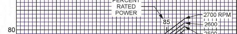
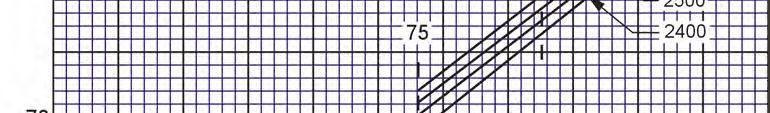
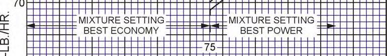


59 SECTION 3 OPERATING INSTRUCTIONS LYCOMING OPERATOR S MANUAL O-360 AND ASSOCIATED MODELS Figure 3-7. Part Throttle Fuel Consumption IO-360-B1A 3-22
60 LYCOMING OPERATOR S MANUAL SECTION 3 O-360 AND ASSOCIATED MODELS OPERATING INSTRUCTIONS Figure 3-8. Part Throttle Fuel Consumption IO-360-B1C 3-23
61 SECTION 3 OPERATING INSTRUCTIONS LYCOMING OPERATOR S MANUAL O-360 AND ASSOCIATED MODELS Figure 3-9. Part Throttle Fuel Consumption IO-360-L2A 3-24
62 LYCOMING OPERATOR S MANUAL SECTION 3 O-360 AND ASSOCIATED MODELS OPERATING INSTRUCTIONS Figure Fuel Flow vs Percent Rated Power TIO-360-A Series 3-25
63 SECTION 3 OPERATING INSTRUCTIONS LYCOMING OPERATOR S MANUAL O-360 AND ASSOCIATED MODELS Figure Fuel Flow vs Percent Rated Power HIO-360-D 3-26
64 LYCOMING OPERATOR S MANUAL SECTION 3 O-360 AND ASSOCIATED MODELS OPERATING INSTRUCTIONS Figure Sea Level and Altitude Performance HIO-360-D (Sheet 1 of 2) 3-27
65 SECTION 3 OPERATING INSTRUCTIONS LYCOMING OPERATOR S MANUAL O-360 AND ASSOCIATED MODELS Figure Sea Level and Altitude Performance HIO-360-D (Sheet 2 of 2) 3-28
66 LYCOMING OPERATOR S MANUAL SECTION 3 O-360 AND ASSOCIATED MODELS OPERATING INSTRUCTIONS Figure Fuel Flow vs Percent Rated Power HIO-360-A Series 3-29
67 SECTION 3 OPERATING INSTRUCTIONS LYCOMING OPERATOR S MANUAL O-360 AND ASSOCIATED MODELS Figure Fuel Flow vs Percent Rated Power HIO-360-B Series 3-30


68 LYCOMING OPERATOR S MANUAL SECTION 3 O-360 AND ASSOCIATED MODELS OPERATING INSTRUCTIONS Figure Fuel Flow vs Percent Rated Power HIO-360-C Series 3-31


69 SECTION 3 OPERATING INSTRUCTIONS LYCOMING OPERATOR S MANUAL O-360 AND ASSOCIATED MODELS Figure Sea Level and Altitude Performance O-360-A, -C (Except those listed for Figure 3-40); HIO-360-A Series 3-32


70 LYCOMING OPERATOR S MANUAL SECTION 3 O-360 AND ASSOCIATED MODELS OPERATING INSTRUCTIONS Figure Sea Level and Altitude Performance O-360-C2B, -C2D 3-33


71 SECTION 3 OPERATING INSTRUCTIONS LYCOMING OPERATOR S MANUAL O-360 AND ASSOCIATED MODELS Figure Sea Level and Altitude Performance O-360-B, -D Series 3-34


72 LYCOMING OPERATOR S MANUAL SECTION 3 O-360 AND ASSOCIATED MODELS OPERATING INSTRUCTIONS Figure Sea Level and Altitude Performance HO-360-B Series 3-35


73 SECTION 3 OPERATING INSTRUCTIONS LYCOMING OPERATOR S MANUAL O-360 AND ASSOCIATED MODELS Figure Sea Level and Altitude Performance IO-360-A, -C, -D, -J, -K; AIO-360 Series 3-36
 HIO-360-G1A")
74 LYCOMING OPERATOR S MANUAL SECTION 3 O-360 AND ASSOCIATED MODELS OPERATING INSTRUCTIONS Figure Sea Level and Altitude Performance IO-360-B, -E, -F Series (Excepting IO-360-B1A, -B1C) HIO-360-G1A 3-37


75 SECTION 3 OPERATING INSTRUCTIONS LYCOMING OPERATOR S MANUAL O-360 AND ASSOCIATED MODELS Figure Sea Level and Altitude Performance IO-360-B1A 3-38 Revised June 2007


76 LYCOMING OPERATOR S MANUAL SECTION 3 O-360 AND ASSOCIATED MODELS OPERATING INSTRUCTIONS Figure Sea Level and Altitude Performance IO-360-B1C 3-39


77 SECTION 3 OPERATING INSTRUCTIONS LYCOMING OPERATOR S MANUAL O-360 AND ASSOCIATED MODELS Figure Sea Level and Altitude Performance IO-360-L2A 3-40


78 LYCOMING OPERATORS MANUAL SECTION 3 O-360 AND ASSOCIATED MODELS OPERATING INSTRUCTIONS Figure Sea Level and Altitude Performance IO-360-, -M1B - For information pertaining to engine model (L)IO-360-M1A, refer to Operation and Installation Manual P/N Revised March
79 SECTION 3 OPERATING INSTRUCTIONS LYCOMING OPERATOR S MANUAL O-360 AND ASSOCIATED MODELS Figure Sea Level and Altitude Performance HIO-360-A Series 3-42
80 LYCOMING OPERATOR S MANUAL SECTION 3 O-360 AND ASSOCIATED MODELS OPERATING INSTRUCTIONS Figure Sea Level and Altitude Performance HIO-360-B Series 3-43


81 SECTION 3 OPERATING INSTRUCTIONS LYCOMING OPERATOR S MANUAL O-360 AND ASSOCIATED MODELS Figure Sea Level and Altitude Performance HIO-360-C Series 3-44


82 LYCOMING OPERATOR S MANUAL SECTION 3 O-360 AND ASSOCIATED MODELS OPERATING INSTRUCTIONS Figure Sea Level and Altitude Performance TIO-360-A Series (Sheet 1 of 5) 3-45


83 SECTION 3 OPERATING INSTRUCTIONS LYCOMING OPERATOR S MANUAL O-360 AND ASSOCIATED MODELS Figure Sea Level and Altitude Performance TIO-360-A Series (Sheet 2 of 5) 3-46


84 LYCOMING OPERATOR S MANUAL SECTION 3 O-360 AND ASSOCIATED MODELS OPERATING INSTRUCTIONS Figure Sea Level and Altitude Performance TIO-360-A Series (Sheet 3 of 5) 3-47


85 SECTION 3 OPERATING INSTRUCTIONS LYCOMING OPERATOR S MANUAL O-360 AND ASSOCIATED MODELS Figure Sea Level and Altitude Performance TIO-360-A Series (Sheet 4 of 5) 3-48

86 LYCOMING OPERATOR S MANUAL SECTION 3 O-360 AND ASSOCIATED MODELS OPERATING INSTRUCTIONS Figure Sea Level and Altitude Performance TIO-360-A Series (Sheet 5 of 5) 3-49
87 SECTION 3 OPERATING INSTRUCTIONS LYCOMING OPERATOR S MANUAL O-360 AND ASSOCIATED MODELS Figure Fuel Flow vs Percent Rated Power HIO-360-E, -F Series 3-50
88 LYCOMING OPERATOR S MANUAL SECTION 3 O-360 AND ASSOCIATED MODELS OPERATING INSTRUCTIONS Figure Sea Level and Altitude Performance HIO-360-E Series 3-51
89 SECTION 3 OPERATING INSTRUCTIONS LYCOMING OPERATOR S MANUAL O-360 AND ASSOCIATED MODELS Figure Sea Level and Altitude Performance with Turbocharger Kit SK HIO-360-E Series 3-52
90 LYCOMING OPERATOR S MANUAL SECTION 3 O-360 AND ASSOCIATED MODELS OPERATING INSTRUCTIONS Figure Fuel Flow vs Percent Rated Power O-360-A, -C, -F, -G Series; HO-360-C1A 3-53
91 SECTION 3 OPERATING INSTRUCTIONS LYCOMING OPERATOR S MANUAL O-360 AND ASSOCIATED MODELS Figure Fuel Flow vs Percent Rated Power O-360-J2A 3-54


92 LYCOMING OPERATOR S MANUAL SECTION 3 O-360 AND ASSOCIATED MODELS OPERATING INSTRUCTIONS Figure Sea Level and Altitude Performance O-360-J2A 3-55


93 SECTION 3 OPERATING INSTRUCTIONS LYCOMING OPERATOR S MANUAL O-360 AND ASSOCIATED MODELS Figure Sea Level and Altitude Performance O-360-A1A, -A1D, -A1P, -A2A, -A2D, -A2F, -A3A, -A4A, -A4D, -A4M, -A4N, -A4P, -A1F6, -A1H6, -C1F, -C1G, -C4F, -C4P, -F1A6; HO-360-C1A 3-56


94 LYCOMING OPERATOR S MANUAL SECTION 3 O-360 AND ASSOCIATED MODELS OPERATING INSTRUCTIONS Figure Sea Level and Altitude Performance HIO-360-F Series 3-57


95 SECTION 3 OPERATING INSTRUCTIONS LYCOMING OPERATOR S MANUAL O-360 AND ASSOCIATED MODELS Figure Sea Level and Altitude Performance with Turbocharger Kit SK HIO-360-F Series 3-58
96 LYCOMING OPERATOR S MANUAL SECTION 3 O-360 AND ASSOCIATED MODELS OPERATING INSTRUCTIONS Figure Fuel Flow vs Brake Horsepower TIO-360-C1A6D 3-59


97 SECTION 3 OPERATING INSTRUCTIONS LYCOMING OPERATOR S MANUAL O-360 AND ASSOCIATED MODELS Figure Sea Level and Altitude Performance TIO-360-C1A6D (Sheet 1 of 3) 3-60


98 LYCOMING OPERATOR S MANUAL SECTION 3 O-360 AND ASSOCIATED MODELS OPERATING INSTRUCTIONS Figure Sea Level and Altitude Performance TIO-360-C1A6D (Sheet 2 of 3) 3-61


99 SECTION 3 OPERATING INSTRUCTIONS LYCOMING OPERATOR S MANUAL O-360 AND ASSOCIATED MODELS Figure Sea Level and Altitude Performance TIO-360-C1A6D (Sheet 3 of 3) 3-62
100 LYCOMING OPERATOR S MANUAL SECTION 4 O-360 AND ASSOCIATED MODELS PERIODIC INSPECTIONS SECTION 4 PERIODIC INSPECTIONS NOTE Perhaps no other factor is quite so important to safety and durability of the aircraft and its components are faithful and diligent attention to regular checks for minor troubles and prompt repair when they are found. The operator should bear in mind that the items listed in the following pages do not constitute a complete aircraft inspection, but are meant for the engine only. Consult the airframe manufacturers handbookfor additional instructions. Pre-Starting Items of Maintenance The daily pre-flight inspection is a checkof the aircraft prior to the first flight of the day. The inspection is to determine the general condition of the aircraft and engine. The importance of proper pre-flight inspection cannot be over emphasized. Statistics prove several hundred accidents occur yearly directly responsible to poor pre-flight. Among the major causes of poor pre-flight inspection are lack of concentration, reluctance to acknowledge the need for a checklist, carelessness bred by familiarity and haste. 4-1
101 SECTION 4 PERIODIC INSPECTIONS LYCOMING OPERATOR S MANUAL O-360 AND ASSOCIATED MODELS 1. DAILY PRE-FLIGHT. a. Engine. (1) Be sure all switches are in the Offposition. (2) Be sure magneto ground wires are connected. (3) Checkoil level. (4) See that fuel tanks are full. (5) Check fuel and oil line connections;note minor indications for repair at 50-hour inspection. Repair any leaks before aircraft is flown. (6) Open the fuel drain to remove any accumulation of water and sediment. (7) Make sure all shields and cowling are in place and secure. If any are missing or damaged, repair or replacement should be made before the aircraft is flown. (8) Checkcontrols for general condition, travel, and freedom of movement. (9) Induction system air filter should be inspected and serviced in accordance with the airframe manufacturers recommendations. b. Turbocharger. (1) Inspect mounting and connections of turbocharger for security, lubricant or air leakage. (2) Checkengine crankcase breather for restrictions to breather HOUR INSPECTION (ENGINE). After the first twenty-five hours operation time;new, rebuilt or newly overhauled engines should undergo a 50-hour inspection including draining and renewing lubricating oil. If engine has no full-flow oil filter, change oil every 25 hours. Also, inspect and clean suction and pressure screens HOUR INSPECTION (ENGINE). In addition to the items listed for daily pre-flight inspection, the following maintenance checks should be made after every 50 hours of operation. 4-2 a. Ignition System. (1) If fouling of sparkplugs is apparent, rotate bottom plugs to upper position. (2) Examine spark plug leads of cable and ceramics for corrosion deposits. This condition is evidence of either leaking sparkplugs, improper cleaning of the sparkplug walls or connector ends. Where this condition is found, clean the cable ends, sparkplug walls and ceramics with a dry, clean cloth or a clean cloth moistened with methyl-ethyl-ketone. All parts should be clean and dry before reassembly.
102 LYCOMING OPERATOR S MANUAL SECTION 4 O-360 AND ASSOCIATED MODELS PERIODIC INSPECTIONS (3) Checkignition harness for security of mounting clamps and be sure connections are tight at spark plug and magneto terminals. b. Fuel and Induction System Checkthe primer lines for leaks and security of the clamps. Remove and clean the fuel inlet strainers. Check the mixture control and throttle linkage for travel, freedom of movement, security of the clamps and lubricate if necessary. Check the air intake ducts for leaks, security, filter damage;evidence of dust or other solid material in the ducts is indicative of inadequate filter care or damaged filter. Checkvent lines for evidence of fuel or oil seepage;if present, fuel pump may require replacement. c. Lubrication System. (1) Replace external full flow oil filter element. (Checkused element for metal particles.) Drain and renew lubricating oil. (2) (Engines Not Equipped with External Filter.) Remove oil pressure screen and clean thoroughly. Note carefully for presence of metal particles that are indicative of internal engine damage. Change oil every 25 hours. (3) Checkoil lines for leaks, particularly at connections for security of anchorage and for wear due to rubbing or vibration, for dents and cracks. d. Exhaust System Checkattaching flanges at exhaust ports on cylinder for evidence of leakage. If they are loose, they must be removed and machined flat before they are reassembled and tightened. Examine exhaust manifolds for general condition. e. Cooling System Check cowling and baffle for damage and secure anchorage. Any damaged or missing part of the cooling system must be repaired or replaced before the aircraft resumes operation. f. Cylinders Check rocker box cover for evidence of oil leaks. If found, replace gasket and tighten screws to specified torque (50 in.-lbs.). Checkcylinders for evidence of excessive heat which is indicated by burned paint on the cylinder. This condition is indicative of internal damage to the cylinder and, if found, its cause must be determined and corrected before the aircraft resumes operation. Heavy discoloration and appearance of seepage at cylinder head and barrel attachment area is usually due to emission of thread lubricant used during assembly of the barrel at the factory, or by slight gas leakage which stops after the cylinder has been in service for awhile. This condition is neither harmful nor detrimental to engine performance and operation. If it can be proven that leakage exceeds these conditions, the cylinder should be replaced. g. Turbocharger All fluid power lines and mounting brackets incorporated in turbocharger system should be checked for leaks, tightness and any damage that may cause a restriction. Checkfor accumulation of dirt or other interference with the linkage between the bypass valve and the actuator which may impair operation of turbocharger. Clean or correct cause of interference. 4-3
103 SECTION 4 PERIODIC INSPECTION LYCOMING OPERATOR S MANUAL O-360 AND ASSOCIATED MODELS The vent line from the actuator should be checked for oil leakage. Any constant oil leakage is cause for replacement of piston seal. Checkalternate air valve to be sure it swings free and seals tightly. h. Carburetor Checkthrottle body attaching screws for tightness. The correct torque for these screws is in.-lbs HOUR INSPECTION. In addition to the items listed for daily pre-flight and 50-hour inspection, the following maintenance checks should be made after every one hundred hours of operation. 4-4 a. Electrical System. (1) Checkall wiring connected to the engine or accessories. Any shielded cables that are damaged should be replaced. Replace clamps or loose wires and check terminals for security and cleanliness. (2) Remove sparkplugs;test, clean and regap. Replace if necessary. b. Lubrication System Drain and renew lubricating oil. c. Magnetos Checkbreaker points for pitting and minimum gap. Checkfor excessive oil in the breaker compartment, if found, wipe dry with a clean lintless cloth. The felt located at the breaker points should be lubricated in accordance with the magneto manufacturers instructions. Checkmagneto to engine timing. Timing procedure is described in Section 5, 1, b of this manual. d. Engine Accessories Engine mounted accessories such as pumps, temperature and pressure sensing units should be checked for secure mounting, tight connections. e. Cylinders Checkcylinders visually for cracked or broken fins. f. Engine Mounts Checkengine mounting bolts and bushings for security and excessive wear. Replace any bushings that are excessively worn. g. Fuel Injection Nozzles and Fuel Lines Checkfuel injector nozzles for looseness, tighten to 60 in.- lbs. torque. Checkfuel line for dye stains at connection indicating leakage and security of line. Repair or replacement must be accomplished before the aircraft resumes operation. h. Turbocharger Inspect all air ducting and connections in turbocharger system for leaks. Make inspection both with engine shut down and with engine running. Checkat manifold connections to turbine inlet and at engine exhaust manifold gasket, for possible exhaust gas leakage. CAUTION DO NOT OPERATE THE TURBOCHARGER IF LEAKS EXIST IN THE DUCTING, OR IF AIR CLEANER IS NOT FILTERING EFFICIENTLY. DUST LEAKING INTO AIR DUCTING CAN DAMAGE TURBOCHARGER AND ENGINE. Checkfor dirt or dust build-up within the turbocharger. Checkfor uneven deposits on the impeller. Consult AiResearch Div. Manual TP-21 for method to remove all such foreign matter.
104 LYCOMING OPERATOR S MANUAL SECTION 4 O-360 AND ASSOCIATED MODELS PERIODIC INSPECTIONS HOUR INSPECTION. In addition to the items listed for daily pre-flight, 50-hour and 100-hour inspection, the following maintenance checkshould be made after every 400 hours of operation. Valve Inspection Remove rocker box covers and check for freedom of valve rockers when valves are closed. Lookfor evidence of abnormal wear or broken parts in the area of the valve tips, valve keeper, springs and spring seats. If any indications are found, the cylinder and all of its components should be removed (including the piston and connecting rod assembly) and inspected for further damage. Replace any parts that do not conform with limits shown in the latest revision of Special Service Publication No. SSP NON-SCHEDULED INSPECTIONS. Occasionally, Service Bulletins or Service Instructions are issued by Lycoming that require inspection procedures that are not listed in this manual. Such publications usually are limited to specified engine models and become obsolete after corrective modification has been accomplished. All such publications are available from Lycoming distributors, or from the factory by subscription. Consult the latest revision of Service Letter No. L114 for subscription information. Maintenance facilities should have an up-to-date file of these publications available at all times. 4-5
105 This Page Intentionally Left Blank
106 LYCOMING OPERATOR S MANUAL SECTION 5 MAINTENANCE PROCEDURES Page General Ignition and Electrical System Ignition Harness and Wire Replacement Timing Magneto to Engine Single Magneto Dual Magneto Generator or Alternator Output Fuel System Repair of Fuel Leaks Carburetor or Fuel Injector Inlet Screen Assembly Fuel Grades and Limitations Air Intake Ducts and Filter Idle Speed and Mixture Adjustment Lubrication System Oil Grades and Limitations Oil Suction and Oil Pressure Screens Oil Pressure Relief Valve Cylinders Generator or Alternator Drive Belt Tension Turbocharger Controls
107 This Page Intentionally Left Blank
108 LYCOMING OPERATOR S MANUAL SECTION 5 O-360 AND ASSOCIATED MODELS MAINTENANCE PROCEDURES SECTION 5 MAINTENANCE PROCEDURES The procedures described in this section are provided to guide and instruct personnel in performing such maintenance operations that may be required in conjunction with the periodic inspections listed in the preceding section. No attempt is made to include repair and replacement operations that will be found in the applicable Lycoming Overhaul Manual. 1. IGNITION AND ELECTRICAL SYSTEM. a. Ignition Harness and Wire Replacement In the event that an ignition harness or an individual lead is to be replaced, consult the wiring diagram to be sure harness is correctly installed. Marklocation of clamps and clips to be certain the replacement is clamped at correct locations. b. Timing Magnetos to Engine. (1) Remove a sparkplug from No. 1 cylinder and place a thumb over the sparkplug hole. Rotate the crankshaft in direction of normal rotation until the compression stroke is reached, this is indicated by a positive pressure inside the cylinder tending to push the thumb off the spark plug hole. Continue rotating the crankshaft until the advance timing markon the front face of the starter ring gear is in alignment with the small hole located at the two oclockposition on the front face of the starter housing. (Ring gear may be marked at 20 and 25. Consult specifications for correct timing markof your installation.) At this point, the engine is ready for assembly of the magnetos. (2) Single Magneto Remove the inspection plugs from both magnetos and turn the drive shaft in direction of normal rotation until (-20 and -200 series) the first painted chamfered tooth on the distributor gear is aligned in the center of the inspection window;(-1200 series) the applicable timing mark on the distributor gear is approximately aligned with the mark on the distributor block. See Figure 5-2. Being sure the gear does not move from this position, install gaskets and magnetos on the engine. Note that an adapter is used with impulse coupling magneto. Secure with (clamps on series) washers and nuts;tighten only finger tight. (3) Using a battery powered timing light, attach the positive lead to a suitable terminal connected to the switch terminal of the magneto and the negative lead to any unpainted portion of the engine. Rotate the magneto in its mounting flange to a point where the light comes on, then slowly turn it in the opposite direction until the light goes out. Bring the magneto backslowly until the light just comes on. Repeat this with the second magneto. (4) Back off the crankshaft a few degrees, the timing lights should go out. Bring the crankshaft slowly back in direction of normal rotation until the timing mark and the hole in the starter housing are in alignment. At this point, both lights should go on simultaneously. Tighten nuts to specified torque. (5) Dual Magnetos Remove the timing window plug from the most convenient side of the housing and the plug from the rotor viewing location in the center of the housing. (6) Turn the rotating magnet drive shaft in direction of normal rotation until the painted tooth of the distributor gear is center in the timing hole. Observe that at this time the built in pointer just ahead of the rotor viewing window aligns with either the L or R (depending on rotation). 5-1
109 SECTION 5 MAINTENANCE PROCEDURES LYCOMING OPERATOR S MANUAL O-360 AND ASSOCIATED MODELS Figure 5-1. Ignition Wiring Diagram Figure 5-2. Timing Marks 4 Cylinder Series 5-2
110 LYCOMING OPERATOR S MANUAL SECTION 5 O-360 AND ASSOCIATED MODELS MAINTENANCE PROCEDURES (7) Hold the magneto in this position and install gasket and magnetos. Secure with clamps, washers and nuts tightened only finger tight. (8) Using a battery powered timing light, attach one positive lead to left switch terminal, one positive lead to right switch terminal and the ground lead to the magneto housing. (9) Turn the entire magneto in direction of rotation until the timing light comes on, then slowly turn it in the opposite direction until the light goes out. Bring the magneto backslowly until the light just comes on. (10) Back off the crankshaft a few degrees, the timing lights should go out. Bring the crankshaft slowly backin direction of normal rotation until the lights just come on. Both lights should go on 2 of No. 1 engine firing position. NOTE Some timing lights operate in the reverse manner as described. The light comes on when the breaker points open. Check your timing light instructions. c. Internal Timing Dual Magneto Checkthe magneto internal timing and breaker synchronization in the following manner. (1) Main Breakers Connect the timing light negative lead to any unpainted surface of the magneto. Connect one positive lead to the left main breaker terminal and the second positive lead to the right main breaker terminal. (2) Backthe engine up a few degrees and again bump forward toward number one cylinder firing position while observing timing lights. Both lights should go out to indicate opening of the main breakers when the timing pointer is indicating within the width of the Lor Rmark. If breaker timing is incorrect, loosen breaker screws and correct. Retorque breaker screws to in.-lbs. (3) Retard Breaker Remove timing light leads from the main breaker terminals. Attach one positive lead to retard breaker terminal, and second positive lead to the tachometer breaker terminal, if used. (4) Backthe engine up a few degrees and again bump forward toward number one cylinder firing position until pointer is aligned with 15 retard timing mark. See Figure 5-6. Retard breaker should just open at this position. (5) If retard timing is not correct, loosen cam securing screw and turn the retard breaker cam as required to make retard breaker open per paragraph c (4). Retorque cam screw to in.-lbs. (6) Observe the tachometer breaker is opened by the cam lobe. No synchronization of this breaker is required. (7) Check action of impulse coupling (D-2000/3000 series only). With the ignition switch off observe breaker cam end of rotor while manually cranking engine through a firing sequence. Rotor should alternately stop and then (with an audible snap) be rotated rapidly through a retard firing position. 5-3
111 SECTION 5 MAINTENANCE PROCEDURES LYCOMING OPERATOR S MANUAL O-360 AND ASSOCIATED MODELS d. Generator or Alternator Output The generator or alternator (whichever is applicable) should be checked to determine that the specified voltage and current are being obtained. 2. FUEL SYSTEM. 5-4 a. Repair of Fuel Leaks In the event a line or fitting in the fuel system is replaced, only a fuel soluble lubricant such as clean engine oil or Loctite Hydraulic Sealant may be used on tapered threads. Do not use Teflon tape or any other form of thread compound. Do not apply sealant to the first two threads. b. Carburetor or Fuel Injector (Except Simmonds Injectors) Fuel Inlet Screen Assembly Remove the assembly and checkthe screen for distortion or openings in the strainer. Replace for either of these conditions. Clean screen assembly in solvent and dry with compressed air and reinstall. The fuel inlet screen assembly is tightened to in.-lbs. on carburetors and in.-lbs. on fuel injectors. The hexhead plug on pressure carburetor is tightened to in.-lbs. c. Fuel Grade and Limitations The recommended aviation grade fuel for the subject engines is listed in Section 3, Item 8. In the event that the specified fuel is not available at some locations, it is permissible to use higher octane fuel. Fuel of a lower octane than specified is not to be used. Under no circumstances should automotive fuel be used (regardless of octane rating). NOTE It is recommended that personnel be familiar with latest revision of Service Instruction No regarding specified fuel for Lycoming engines. d. Air Intake Ducts and Filter Checkall air intake ducts for dirt or restrictions. Inspect and service air filters as instructed in the airframe manufacturers handbook. e. Idle Speed and Mixture Adjustment. (1) Start the engine and warm up in the usual manner until oil and cylinder head temperatures are normal. (2) Checkmagnetos. If the mag-dropis normal, proceed with idle adjustment. (3) Set throttle stop screw so that the engine idles at the airframe manufacturers recommended idling RPM. If the RPM changes appreciably after making idle mixture adjustment during the succeeding steps, readjust the idle speed to the desired RPM. (4) When the idling speed has been stabilized, move the cockpit mixture control lever with a smooth, steady pull toward the Idle Cut-Offposition and observe the tachometer for any change during the leaning process. Caution must be exercised to return the mixture control to the Full Rich position before the RPM can drop to a point where the engine cuts out. An increase of more than 50 RPM while leaning outindicates an excessively rich idle mixture. An immediate decrease in RPM (if not preceded by a momentary increase) indicates the idle mixture is too lean.
112 LYCOMING OPERATOR S MANUAL SECTION 5 O-360 AND ASSOCIATED MODELS MAINTENANCE PROCEDURES If step (4) indicates that the idle adjustment is too rich or too lean, turn the idle mixture adjustment in direction required for correction, and checkthis new position by repeating the above procedure. Make additional adjustments as necessary until a checkresults in a momentary pick-up of approximately 50 RPM. Each time the adjustment is changed, the engine should be run up to 2000 RPM to clean the engine before proceeding with the RPM check. Make final adjustment of the idle speed adjustment to obtain the desired idling RPM with closed throttle. The above method aims at a setting that will obtain maximum RPM with minimum manifold pressure. In case the setting does not remain stable, checkthe idle linkage;any looseness in this linkage would cause erratic idling. In all cases, allowance should be made for the effect of weather conditions and field altitude upon idling adjustment. 3. LUBRICATION SYSTEM. a. Oil Grades and Limitations Service the engine in accordance with the recommended grade oil as specified in Section 3, Item 8. b. Oil Suction and Oil Pressure Screens At each 100-hour inspection remove suction screen. Inspect for metal particles;clean and reinstall. Inspect and clean pressure screen every 25 hours. c. Oil Pressure Relief Valve Subject engines may be equipped with either an adjustable or nonadjustable oil pressure relief valve. A brief description of both types follows: (1) Non-Adjustable Oil Pressure Relief Valve The function of the oil pressure relief valve is to maintain engine oil pressure within specified limits. The valve, although not adjustable, may control the oil pressure with the addition of a maximum of nine (9) P/N STD-425 washers between the cap and spring to increase the pressure. Removal of the washers will decrease the oil pressure. Some early model engines use a maximum of three (3) P/N STD-425 washers to increase the oil pressure and the use of a P/N or P/N spacer between the cap and crankcase to decrease the oil pressure. Particles of metal or other foreign matter lodged between the ball and seal will result in faulty readings. It is advisable, therefore, to disassemble, inspect and clean the valve if excessive pressure fluctuations are noted. (2) Oil Pressure Relief Valve (Adjustable) The adjustable oil relief valve enables the operator to maintain engine oil pressure within the specified limits. If pressure under normal operating conditions should consistently exceed the maximum or minimum specified limits, adjust the valve as follows: With the engine warmed up and running at approximately 2000 RPM, observe the reading on the oil pressure gage. If the pressure is above maximum or below minimum specified limits, stop engine and screw the adjusting screw outward to decrease pressure or inward to increase pressure. Depending on installation, the adjusting screw may have only a screw driver slot and is turned with a screw driver;or may have the screw driver slot plus a pinned castellated nut and may be turned with either a screw driver or a boxwrench. 4. CYLINDERS. It is recommended that as a field operation, cylinder maintenance be confined to replacement of the entire assembly. For valve replacement, consult the proper overhaul manual. This should be undertaken only as an emergency measure. 5-5
113 SECTION 5 MAINTENANCE PROCEDURES LYCOMING OPERATOR S MANUAL O-360 AND ASSOCIATED MODELS 5-6 a. Removal of Cylinder Assembly. (1) Remove exhaust manifold. (2) Remove rocker box drain tube, intake pipe, baffle and any clips that might interfere with the removal of the cylinder. (3) Disconnect ignition cables and remove the bottom sparkplug. (4) Remove rocker boxcover and rotate crankshaft until piston is approximately at top center of the compression stroke. This is indicated by a positive pressure inside of cylinder tending to push thumb off of bottom sparkplug hole. (5) Slide valve rocker shafts from cylinder head and remove the valve rockers. Valve rocker shafts can be removed when the cylinder is removed from the engine. Remove rotator cap from exhaust valve stem. (6) Remove push rods by grasping ball end and pulling rod out of shroud tube. Detach shroud tube spring and lockplate and pull shroud tubes through holes in cylinder head. NOTE The hydraulic tappets, push rods, rocker arms and valves must be assembled in the same location from which they were removed. (7) Remove cylinder base nuts and hold down plates (where employed) then remove cylinder by pulling directly away from crankcase. Be careful not to allow the piston to drop against the crankcase, as the piston leaves the cylinder. b. Removal of Piston from Connecting Rod Remove the piston pin plugs. Insert piston pin puller through piston pin, assemble puller nut;then proceed to remove piston pin. Do not allow connecting rod to rest on the cylinder bore of the crankcase. Support the connecting rod with heavy rubber band, discarded cylinder base oil ring seal, or any other non-marring method. c. Removal of Hydraulic Tappet Sockets and Plunger Assemblies It will be necessary to remove and bleed the hydraulic tappet plunger assembly so that dry tappet clearance can be checked when the cylinder assembly is reinstalled. This is accomplished in the following manner: (1) Remove the hydraulic tappet push rod socket by inserting the forefinger into the concave end of the socket and withdrawing. If the socket cannot be removed in this manner, it may be removed by grasping the edge of the socket with a pair of needle nose pliers. However, care must be exercised to avoid scratching the socket. (2) To remove the hydraulic tappet plunger assembly, use the special Lycoming service tool. In the event the tool is not available, the hydraulic tappet plunger assembly may be removed by a hook in the end of a short piece of lockwire, inserting the wire so that the hookengages the spring of the plunger assembly. Draw the plunger assembly out of the tappet body by gently pulling the wire.
114 LYCOMING OPERATOR S MANUAL SECTION 5 O-360 AND ASSOCIATED MODELS MAINTENANCE PROCEDURES CAUTION NEVER USE A MAGNET TO REMOVE HYDRAULIC PLUNGER ASSEMBLIES FROM THE CRANKCASE. THIS CAN CAUSE THE CHECK BALL TO REMAIN OFF ITS SEAT, RENDERING THE UNIT INOPERATIVE. d. Assembly of Hydraulic Tappet Plunger Assemblies To assemble the unit, unseat the ball by inserting a thin clean wire through the oil inlet hole. With the ball off its seat, insert the plunger and twist clockwise so that the spring catches. All oil must be removed before the plunger is inserted. e. Assembly of Cylinder and Related Parts Rotate the crankshaft so that the connecting rod of the cylinder being assembled is at the top center of compression stroke. This can be checked by placing two fingers on the intake and exhaust tappet bodies. Rockcrankshaft backand forth over top center. If the tappet bodies do not move the crankshaft is on the compression stroke. (1) Place each plunger assembly in its respective tappet body and assemble the socket on top of plunger assembly. (2) Assemble piston with rings so that the number stamped on the piston pin boss is toward the front of the engine. The piston pin should be a handpush fit. If difficulty is experienced in inserting the piston pin, it is probably caused by carbon or burrs in the piston pin hole. During assembly, always use a generous quantity of oil, both in the piston hole and on the piston pin. (3) Assemble one piston pin plug at each end of the piston pin and place a new rubber oil seal ring around the cylinder skirt. Coat piston and rings and the inside of the cylinder generously with oil. (4) Using a piston ring compressor, assemble the cylinder over the piston so that the intake port is at the bottom of the engine. Push the cylinder all the way on, catching the ring compressor as it is pushed off. NOTE Before installing cylinder hold-down nuts, lubricate crankcase thru-stud threads with any one of the following lubricants, or combination of lubricants 1. 90% SAE 50W engine oil and 10% STP. 2. Parker Thread Lube % SAE 30 engine oil and 40% Parker Thread Lube. (5) Assemble hold-down plates (where applicable) and cylinder base hold-down nuts and tighten as directed in the following steps. NOTE At any time a cylinder is replaced, it is necessary to retorque the thru-studs on the cylinder on the opposite side of the engine. (a) (Engines using hold-down plates) Install shims between cylinder base hold-down plates and cylinder barrel, as directed in Figure 5-3, and tighten ½ inch hold-down nuts to 300 in.-lbs. (25 ft.-lbs.) torque, using the sequence shown in Figure
115 SECTION 5 MAINTENANCE PROCEDURES LYCOMING OPERATOR S MANUAL O-360 AND ASSOCIATED MODELS (b) Remove shims, and using the same sequence, tighten the ½ inch cylinder base nuts to 600 in.- lbs. (50 ft.-lbs.) torque. NOTE Cylinder assemblies not using hold-down plate are tightened in the same manner as above omitting the shims. Figure 5-3. Location of Shims Between Cylinder Barrel and Hold-Down Plates (where applicable) and Sequence of Tightening Cylinder Base Hold-Down Nuts 5-8
116 LYCOMING OPERATOR S MANUAL SECTION 5 O-360 AND ASSOCIATED MODELS MAINTENANCE PROCEDURES (c) Tighten the inch hold-down nuts to 300 in.-lbs. (25 ft.-lbs.) torque. Sequence of tightening is optional. (d) As a final check, hold the torque wrench on each nut for about five seconds. If the nut does not turn, it may be presumed to be tightened to correct torque. CAUTION AFTER ALL CYLINDER BASE NUTS HAVE BEEN TIGHTENED, REMOVE ANY NICKS IN THE CYLINDER FINS BY FILING OR BURRING. (6) Install new shroud tube oil seals on both ends of shroud tube. Install shroud tube and lockin place as required for type of cylinder. (7) Assemble each push rod in its respective shroud tube, and assemble each rocker in its respective position by placing rocker between bosses and sliding valve rocker shaft in place to retain rocker. Before installing exhaust valve rocker, place rotator cap over end of exhaust valve stem. (8) Be sure that the piston is at top center of compression stroke and that both valves are closed. Checkclearance between the valve stem tip and the valve rocker. In order to checkthis clearance, place the thumb of one hand on the valve rocker directly over the end of the push rod and push down so as to compress the hydraulic tappet spring. While holding the spring compressed, the valve clearance should be between.028and.080 inch. If clearance does not come within these limits, remove the push rod and insert a longer or shorter push rod, as required, to correct clearance. NOTE Inserting a longer push rod will decrease the valve clearance. (9) Install intercylinder baffles, rocker boxcovers, intake pipes, rocker boxdrain tubes and exhaust manifold. 5. GENERATOR OR ALTERNATOR DRIVE BELT TENSION. Checkthe tension of a new belt 25 hours after installation. Refer to latest revision of Service Instruction No and latest revision of Service Letter No. L160 for methods of checking generator or alternator drive belt tension. 6. TURBOCHARGER CONTROLS. a. Density Controller The density controller is adjusted at the factory to maintain a predetermined constant for desired horsepower. The density controller is set to the curve, see Figure 5-4, under the following conditions: Engine stabilized at operating conditions, full throttle with oil pressure at 80 psi ±5 psi. If it is suspected that the manifold pressure is not within limits, it may be checked to the curve. EXAMPLE Operating at the stated conditions with a compressor discharge temperature of 120 F, the manifold pressure should be 34.8 in. Hg. ±.3 in. Hg. 5-9
117 SECTON 5 MAINTENANCE PROCEDURES LYCOMING OPERATOR S MANUAL O-360 AND ASSOCIATED MODELS If the manifold pressure is found to be out of limits, the cause might be found either in the density controller, the differential pressure controller, or the waste gate. It is recommended that an authorized overhaul facility checkthese controls. Exhaust Bypass Valve (TIO-360-A Series). This valve is actuated by engine oil pressure and is set to predetermined open and closed clearances. These clearances and the procedures for setting them are shown in Figure 5-5. Exhaust Bypass Valve (TIO-360-C1A6D). This valve is mechanically controlled by a flexible linkage connected to the injector throttle arm and the wastegate control arm. Adjust linkage as follows: (1) Move injector throttle arm to full open position. (2) Insert a inch feeler gage between the bypass butterfly valve, in the closed position, and the bypass housing. (3) Adjust linkage until the bypass valve control arm is at the full closed stop position. 5-10
118 LYCOMING OPERATOR S MANUAL SECTION 5 O-360 AND ASSOCIATED MODELS MAINTENANCE PROCEDURES Figure 5-4. Density Control Full Throttle Setting Limits 5-11
119 SECTION 5 MAINTENANCE PROCEDURES LYCOMING OPERATOR S MANUAL O-360 AND ASSOCIATED MODELS Figure 5-5. Exhaust Bypass Valve Open and Closed Setting Figure 5-6. Timing Marks on Rotating Magnet 5-12

120 LYCOMING OPERATOR S MANUAL SECTION 5 O-360 AND ASSOCIATED MODELS MAINTENANCE PROCEDURES Figure 5-7. Ignition Wiring Diagram, Dual Magneto 5-13
121 This Page Intentionally Left Blank
122 LYCOMING OPERATOR S MANUAL SECTION 6 TROUBLE-SHOOTING ENGINE Page Failure of Engine to Start Failure of Engine to Idle Properly Low Power and Uneven Running Failure of Engine to Develop Full Power Rough Engine Low Oil Pressure High Oil Temperature Excessive Oil Consumption TROUBLE-SHOOTING TURBOCHARGER Excessive Noise or Vibration Engine Will Not Deliver Rated Power Critical Altitude Lower Than Specified Engine Surges or Smokes High Deck Pressure
123 This Page Intentionally Left Blank
124 LYCOMING OPERATOR S MANUAL SECTION 6 O-360 AND ASSOCIATED MODELS TROUBLE-SHOOTING SECTION 6 TROUBLE-SHOOTING Experience has proven that the best method of trouble-shooting is to decide on the various causes of a given trouble and then to eliminate causes one by one, beginning with the most probable. The following charts list some of the more common troubles, which may be encountered in maintaining engines and turbochargers;their probable causes and remedies. 1. TROUBLE-SHOOTING ENGINE. TROUBLE PROBABLE CAUSE REMEDY Failure of Engine to Start Lackof fuel Checkfuel system for leaks. Fill fuel tank. Clean dirty lines, strainers, or fuel valves. Overpriming Defective sparkplugs Defective ignition wire Defective battery Improper operation of magneto breaker Lackof sufficient fuel flow Water in fuel injector or carb. Internal failure Leave ignition offand mixture control in Idle Cut-Off, open throttle and unloadengine by cranking for a few seconds. Turn ignition switch on and proceed to start in a normal manner. Clean and adjust or replace spark plugs. Checkwith electric tester, and replace any defective wires. Replace with charged battery. Clean points. Checkinternal timing of magnetos. Disconnect fuel line and check fuel flow. Drain fuel injector or carburetor and fuel lines. Checkoil screens for metal particles. If found, complete overhaul of the engine may be indicated. 6-1
125 SECTION 6 TROUBLE-SHOOTING LYCOMING OPERATOR S MANUAL O-360 AND ASSOCIATED MODELS TROUBLE PROBABLE CAUSE REMEDY Failure of Engine to Idle Properly Incorrect idle mixture Adjust mixture. Leakin the induction system Incorrect idle mixture Uneven cylinder compression Faulty ignition system Insufficient fuel pressure Tighten all connections in the induction system. Replace any parts that are defective. Adjust throttle stop to obtain correct idle. Checkcondition of piston rings and valve seats. Checkentire ignition system. Adjust fuel pressure. Low Power and Uneven Running Mixture too rich indicated by Readjustment of fuel injector or sluggish engine operation, red carburetor by authorized exhaust flame at night. Extreme personnel is indicated. cases indicated by blacksmoke from exhaust. Mixture too lean indicated by overheating or backfiring Leaks in induction system Defective sparkplugs Improper fuel Magneto breaker points not working properly Defective ignition wire Defective sparkplug terminal connectors Checkfuel lines for dirt or other restrictions. Readjustment of fuel injector or carburetor by authorized personnel is indicated. Tighten all connections. Replace defective parts. Clean and gap or replace spark plugs. Fill tankwith fuel of recommended grade. Clean points. Checkinternal timing of magnetos. Checkwire with electric tester. Replace defective wire. Replace connectors on sparkplug wire. 6-2
126 LYCOMING OPERATOR S MANUAL SECTION 6 O-360 AND ASSOCIATED MODELS TROUBLE-SHOOTING TROUBLE PROBABLE CAUSE REMEDY Failure of Engine to Develop Leakin the induction system Tighten all connections and Full Power replace defective parts. Throttle lever out of adjustment Improper fuel flow Restriction in air scoop Improper fuel Faulty ignition Adjust throttle lever. Checkstrainer, gage and flow at the fuel inlet. Examine air scoop and remove restrictions. Drain and refill tankwith recommended fuel. Tighten all connections. Check system with tester. Check ignition timing. Rough Engine Cracked engine mount Replace or repair mount. Defective mounting bushings Uneven compression Install new mounting bushings. Checkcompression. Low Oil Pressure Insufficient oil Fill to proper level with recommended oil. Air lockor dirt in relief valve Leakin suction line or pressure line High oil temperature Defective pressure gage Stoppage in oil pump intake passage Remove and clean oil pressure relief valve. Checkgasket between accessory housing and crankcase. See High Oil Temperaturein Troublecolumn. Replace. Checkline for obstruction. Clean suction strainer. High Oil Temperature Insufficient air cooling Checkair inlet and outlet for deformation or obstruction. Insufficient oil supply Fill to proper level with specified oil. 6-3
127 SECTION 6 TROUBLE-SHOOTING LYCOMING OPERATOR S MANUAL O-360 AND ASSOCIATED MODELS TROUBLE PROBABLE CAUSE REMEDY High Oil Temperature (Cont.) Low grade of oil Replace with oil conforming to specifications. Clogged oil lines or strainers Excessive blow-by Defective temperature gage Remove and clean oil strainers. Usually caused by worn or stuck rings. Replace gage. Excessive Oil Consumption Low grade of oil Fill tankwith oil conforming to specifications. Failing or failed bearings Worn piston rings Incorrect installation of piston rings Failure of rings to seat (new nitrided cylinders) Checksump for metal particles. Install new rings. Install new rings. Use mineral base oil. Climb to cruise altitude at full power and operate at 75% cruise power setting until oil consumption stabilizes. 2. TROUBLE-SHOOTING TURBOCHARGER. TROUBLE PROBABLE CAUSE REMEDY Excessive Noise or Vibration Improper bearing lubrication Supply required oil pressure. Clean or replace oil line;clean oil strainer. If trouble persists, overhaul turbocharger. Leakin engine intake or exhaust manifold Dirty impeller blades Tighten loose connections or replace manifold gaskets as necessary. Disassemble and clean. Engine Will Not Deliver Clogged manifold system Clear all ducting. Rated Power Foreign material lodged in compressor impeller or turbine Disassemble and clean. 6-4
128 LYCOMING OPERATOR S MANUAL SECTION 6 O-360 AND ASSOCIATED MODELS TROUBLE-SHOOTING TROUBLE PROBABLE CAUSE REMEDY Engine Will Not Deliver Excessive dirt build-up in Thoroughly clean compressor Rated Power (Cont.) compressor assembly. Service air cleaner and checkfor leakage. Rotating assembly bearing seizure Restrictions in return lines from actuator to waste gate controller Exhaust bypass controller is in need of adjustment Oil pressure too low Inlet orifice to actuator clogged Exhaust bypass controller malfunction Exhaust bypass butterfly not closing Overhaul turbocharger. Remove and clean lines. Have exhaust bypass controller adjusted. Tighten fittings. Replace lines or hoses. Increase oil pressure to desired pressure. Remove inlet line at actuator and clean orifice. Replace unit. Low pressure. Clogged orifice in inlet to actuator. Butterfly shaft binding. Check bearings. Turbocharger impeller binding, frozen or fouling housing Piston seal in actuator leaking. (Usually accompanied by oil leakage at drain line.) Checkbearings. Replace turbocharger. Remove and replace actuator or disassemble and replace packing. Critical Altitude Lower Than Controller not getting enough oil Checkpump outlet pressure, oil Specified pressure to close the waste gate filters, external lines for leaks or obstructions. Chips under metering valve in controller holding it open Metering jet in actuator plugged Actuator piston seal failed and leaking excessively Replace controller. Remove actuator and clean jet. If there is oil leakage at actuator drain, clean cylinder and replace piston seal. 6-5
129 SECTION 6 TROUBLE-SHOOTING LYCOMING OPERATOR S MANUAL O-360 AND ASSOCIATED MODELS TROUBLE PROBABLE CAUSE REMEDY Critical Altitude Lower Than Exhaust bypass valve sticking Clean and free action. Specified (Cont.) Engine Surges or Smokes Air in oil lines or actuator Bleed system. Controller metering valve stem seal leaking oil into manifold Clogged breather Replace controller. Checkbreather for restrictions to air flow. NOTE Smoke would be normal if engine has idled for a prolonged period. High DeckPressure (Compressor Controller metering valve not Replace controller assembly or Discharge Pressure) opening, aneroid bellows leaking replace aneroid bellows. Exhaust bypass sticking closed Shut off valve in return line not working. Butterfly shaft binding. Check bearings. Replace bypass valve or correct linkage binding. Controller return line restricted Clean or replace line. Oil pressure too high Checkpressure 75 to 85 psi (80 psi desired) at exhaust bypass actuator desired. If pressure on outlet side of actuator is too high, have exhaust bypass controller adjusted. Exhaust bypass actuator piston locked in full closed position. (Usually accompanied by oil leakage at actuator drain line.) NOTE:Exhaust bypass normally closed in idle and low power condition. Should open when actuator inlet line is disconnected. Exhaust bypass controller malfunction Remove and disassemble actuator, checkcondition of piston and packing or replace actuator assembly. Replace controller. 6-6
130 LYCOMING OPERATOR S MANUAL SECTION 7 INSTALLATION AND STORAGE Page Preparation of Engine for Installation General Inspection of Engine Mounting Attaching Engine to Mounts Oil and Fuel Line Connections Propeller Installation Preparation of Carburetors and Fuel Injectors for Installation Corrosion Prevention in Engines Installed in Inactive Aircraft
131 This Page Intentionally Left Blank
132 LYCOMING OPERATOR S MANUAL SECTION 7 O-360 AND ASSOCIATED MODELS INSTALLATION AND STORAGE SECTION 7 INSTALLATION AND STORAGE 1. PREPARATION OF ENGINE FOR INSTALLATION. Before installing an engine that has been prepared for storage, remove all dehydrator plugs, bags of desiccant and preservative oil from the engine. Preservative oil can be removed by removing the bottom sparkplugs and turning the crankshaft three or four revolutions by hand. The preservative oil will then drain through the sparkplug holes. Draining will be facilitated if the engine is tilted from side to side during the above operation. Preservative oil which has accumulated in the sump can be drained by removing the oil sump plug. Engines that have been stored in a cold place should be removed to an environment of at least 70 F (21 C) for a period of 24 hours before preservative oil is drained from the cylinders. If this is not possible, heat the cylinders with heat lamps before attempting to drain the engine. After the oil sump has been drained, the plug should be replaced and safety-wired. Fill the sump or external tankwith lubricating oil. The crankshaft should again be turned several revolutions to saturate the interior of the engine with the clean oil. When installing sparkplugs, make sure that they are clean, if not, wash them in clean petroleum solvent. Of course, there will be a small amount of preservative oil remaining in the engine, but this can cause no harm. However, after twenty-five hours of operation, the lubricating oil should be drained while the engine is hot. This will remove any residual preservative oil that may have been present. CAUTION DO NOT ROTATE THE CRANKSHAFT OF AN ENGINE CONTAINING PRESERVATIVE OIL BEFORE REMOVING THE SPARK PLUGS, BECAUSE IF THE CYLINDERS CONTAIN ANY APPRECIABLE AMOUNT OF THE MIXTURE, THE RESULTING ACTION, KNOWN AS HYDRAULICING, WILL CAUSE DAMAGE TO THE ENGINE. ALSO, ANY CONTACT OF THE PRESERVATIVE OIL WITH PAINTED SURFACES SHOULD BE AVOIDED. General Should any of the dehydrator plugs, containing crystals of silica-gel or similar material, be broken during their term of storage or upon their removal from the engine, and if any of the contents should fall into the engine, that portion of the engine must be disassembled and thoroughly cleaned before using the engine. The oil strainers should be removed and cleaned in gasoline or some other hydrocarbon solvent. The fuel drain screen located in the fuel inlet of the carburetor or fuel injector should also be removed and cleaned in a hydrocarbon solvent. The operator should also note if any valves are sticking. If they are, this condition can be eliminated by coating the valve stem generously with a mixture of gasoline and lubrication oil. Inspection of Engine Mounting If the aircraft is one from which an engine has been removed, make sure that the engine mount is not bent or damaged by distortion or misalignment as this can produce abnormal stresses with the engine. Attaching Engine to Mounts See airframe manufacturers recommendations for method of mounting the engine. Oil and Fuel Line Connections The oil and fuel line connections are called out on the accompanying installation drawings. 7-1
133 SECTION 7 INSTALLATION AND STORAGE LYCOMING OPERATOR S MANUAL O-360 AND ASSOCIATED MODELS Propeller Installation Consult the airframe manufacturer for information relative to propeller installation. 1. PREPARATION OF CARBURETORS AND FUEL INJECTORS FOR INSTALLATION. Carburetors and fuel injectors that have been prepared for storage should undergo the following procedures before being placed in service. Carburetor (MA-4-5, MA-4-5AA) Remove the fuel drain plug and drain preservative oil. Remove the fuel inlet strainer assembly and clean in a hydrocarbon solvent. Reinstall the fuel drain plug and fuel inlet strainer assembly. Carburetor (PSH-5BD) Remove the fuel inlet strainer and all plugs leading to the fuel chambers. Drain preservative oil from the carburetor. Clean the fuel inlet strainer in a hydrocarbon solvent. Reinstall fuel inlet strainer and replace all plugs. Remove plug opposite the manual mixture control needle and drain any accumulated moisture from the air chamber. Replace plug. With the throttle lever in the wide open position and the manual mixture control in the full rich position, inject clean fuel through the fuel inlet connection at 5 psi until clean fuel flows from the discharge nozzle. CAUTION DO NOT ALLOW FUEL OR OIL TO ENTER INTO THE AIR CHAMBER. Move the throttle lever to the closed position and the mixture control lever to the idle cut-off position. Because this carburetor has a closed fuel system, it will remain full of fuel as long as the mixture control lever is in the idle cut-off position. NOTE It is necessary that this carburetor soak for an eight hour period before starting the engine. The soaking period may be performed prior to or after installation on the engine. Fuel Injector (Bendix) Remove and clean the fuel inlet strainer assembly and reinstall. Inject clean fuel into the fuel inlet connection with the fuel outlets uncapped until clean fuel flow from the outlets. Do not exceed 15 psi inlet pressure. CORROSION PREVENTION IN ENGINES INSTALLED IN INACTIVE AIRCRAFT Corrosion can occur, especially in new or overhauled engines, on cylinder walls of engines that will be inoperative for periods as brief as two days. Therefore, the following preservation procedure is recommended for inactive engines and will be effective in minimizing the corrosion condition for a period up to thirty days. 7-2 NOTE Ground running the engine for brief periods of time is not a substitute for the following procedure; in fact, the practice of ground running will tend to aggravate rather than minimize this corrosion condition
134 LYCOMING OPERATOR S MANUAL SECTION 7 O-360 AND ASSOCIATED MODELS INSTALLATION AND STORAGE a. As soon as possible after the engine is stopped, move the aircraft into the hangar, or other shelter where the preservation process is to be performed. b. Remove sufficient cowling to gain access to the sparkplugs and remove both sparkplugs from each cylinder. c. Spray the interior of each cylinder with approximately two (2) ounces of corrosion preventive oil while cranking the engine about five (5) revolutions with the starter. The spray gun nozzle may be placed in either of the sparkplug holes. NOTE Spraying should be accomplished using an airless spray gun (Spraying Systems Co., Gunjet Model 24A-8395 or equivalent). In the event an airless spray gun is not available, personnel should install a moisture trap in the air line of a conventional spray gun and be certain oil is hot at the nozzle before spraying cylinders. d. With the crankshaft stationary, again spray each cylinder through the spark plug holes with approximately two (2) ounces of corrosion preventive oil. Assemble spark plugs and do not turn crankshaft after cylinders have been sprayed. The corrosion preventive oil to be used in the foregoing procedure should conform to specification MIL- L-6529, Type 1, heated to 200 F/220 F (93 C/104 C) spray nozzle temperature. It is not necessary to flush preservative oil from the cylinder prior to flying the aircraft. The small quantity of oil coating the cylinders will be expelled from the engine during the first few minutes of operation. NOTE Oils of the type mentioned are to be used in Lycoming aircraft engines for corrosion prevention only, and not for lubrication. See the latest revision of Lycoming Service Instruction No and latest revision of Service Bulletin No. 318 for recommended lubricating oil. 7-3


135 SECTION 7 INSTALLATION AND STORAGE LYCOMING OPERATOR S MANUAL O-360 AND ASSOCIATED MODELS Figure 7-1. Fuel Metering System 7-4


136 LYCOMING OPERATOR S MANUAL SECTION 7 O-360 AND ASSOCIATED MODELS INSTALLATION AND STORAGE Figure 7-2. Magneto Connections 7-5
137 SECTION 7 INSTALLATION AND STORAGE LYCOMING OPERATOR S MANUAL O-360 AND ASSOCIATED MODELS Figure 7-3. Optional Oil Cooler Connections 7-6


138 LYCOMING OPERATOR S MANUAL SECTION 7 O-360 AND ASSOCIATED MODELS INSTALLATION AND STORAGE Figure 7-4. Installation Drawing O-360-A, -B Series (Except A1C, -A1G) 7-7
139 SECTION 7 INSTALLATION AND STORAGE LYCOMING OPERATOR S MANUAL O-360 AND ASSOCIATED MODELS Figure 7-5. Installation Drawing O-360-A1C, IO-360-B1C 7-8

140 LYCOMING OPERATOR S MANUAL SECTION 7 O-360 AND ASSOCIATED MODELS INSTALLATION AND STORAGE Figure 7-6. Installation Drawing O-360-C, -D Series (Except -C2B, -C2D) 7-9

141 SECTION 7 INSTALLATION AND STORAGE LYCOMING OPERATOR S MANUAL O-360 AND ASSOCIATED MODELS Figure 7-7. Installation Drawing O-360-C1B, -C1D;HO-360-B1A, -B1B 7-10
142 LYCOMING OPERATOR S MANUAL SECTION 7 O-360 AND ASSOCIATED MODELS INSTALLATION AND STORAGE Figure 7-8. Installation Drawing IO-360-A Series 7-11

143 SECTION 7 INSTALLATION AND STORAGE LYCOMING OPERATOR S MANUAL O-360 AND ASSOCIATED MODELS Figure 7-9. Installation Drawing IO-360-B1A 7-12


144 LYCOMING OPERATOR S MANUAL SECTION 7 O-360 AND ASSOCIATED MODELS INSTALLATION AND STORAGE Figure Installation Drawing IO-360-B1B, -B1D 7-13
IO-360, AIO-360, HIO-360 & TIO-360 Series
 Operator s Manual Lycoming O-360, HO-360, IO-360, AIO-360, HIO-360 & TIO-360 Series Approved by FAA 8 th Edition Part No. 60297-12 652 Oliver Street Williamsport, PA. 17701 U.S.A. 570/323-6181 October
European Aviation Safety Agency
 European Aviation Safety Agency EASA TYPE-CERTIFICATE DATA SHEET Number: IM.E.032 Issue: 01 Date: 27 September 2012 Type: Lycoming Engines Models IO-360-A1A IO-360-C1B AEIO-360-A1E6 HIO-360-F1AD IO-360-A1B
DEPARTMENT OF TRANSPORTATION FEDERAL AVIATION ADMINISTRATION
 DEPARTMENT OF TRANSPORTATION FEDERAL AVIATION ADMINISTRATION 1E10 Revision No. 22 TEXTRON Lycoming IO-360-A1A, -A1B, -A1B6, -A1B6D, -A1C, -A1D, -A1D6, -A1D6D, -A2A, -A2B, -A2C, -A3B6,-A3B6D, -A3D6D, -B1A,
IO-360, AIO-360, HIO-360 & TIO-360 Series
 Operator s Manual Lycoming O-360, HO-360, IO-360, AIO-360, HIO-360 & TIO-360 Series Approved by FAA 8 th Edition Part No. 60297-12 652 Oliver Street Williamsport, PA. 17701 U.S.A. 570/323-6181 October
DEPARTMENT OF TRANSPORTATION FEDERAL AVIATION ADMINISTRATION TYPE CERTIFICATE DATA SHEET NO. 1E12
 DEPARTMENT OF TRANSPORTATION FEDERAL AVIATION ADMINISTRATION TYPE CERTIFICATE DATA SHEET NO. 1E12 1E12 Revision 9 Lycoming Engines IO-320 -A1A-A2A-B1A, -B1B, B1C, -B1E, -B1D, -B2A, -C1A, -C1B, -D1A, -D1C,
YIO-390-B Series Operation and Installation Manual
 YIO-390-B Series Operation and Installation Manual November 2009 Part No. 60297-37 2009 652 Oliver Street Williamsport, PA 17701 YIO-390-B Series Operation and Installation Manual November 2009 Part No.
DEPARTMENT OF TRANSPORTATION FEDERAL AVIATION ADMINISTRATION TYPE CERTIFICATE DATA SHEET NO. E-223
 DEPARTMENT OF TRANSPORTATION FEDERAL AVIATION ADMINISTRATION E-223 Revision 18 Textron Lycoming O-233-A1,O-235 O-235-A,-B,-AP,-BP-C,-C1,-C1A,-C1B,-C1C,-C2A,-C2B,-C2C, -E1,-E1B,-E2A,-E2B,-F1,-F1B,-F2A,-F2B,-G1,-G1B,-G2A,-G2B,
IO 390 A Series Operation and Installation Manual
 IO 390 A Series Operation and Installation Manual August 2008 (Cover Revised June 2009) FAA Approved Part No. 60297 34 2008 652 Oliver Street Williamsport, PA 17701 IO 390 A Series Operation and Installation
O-540, IO-540 Series
 Operator s Manual Lycoming O-540, IO-540 Series Approved by FAA 4 th Edition Part No. 60297-10 652 Oliver Street Williamsport, PA. 17701 U.S.A. 570/323-6181 June 2006 O-540, IO-540 Series Operator s Manual
IO-720 Series. Operator s Manual Lycoming. Approved by FAA. 4 th Edition Part No
 Operator s Manual Lycoming IO-720 Series Approved by FAA 4 th Edition Part No. 60297-19 652 Oliver Street Williamsport, PA. 17701 U.S.A. 570/323-6181 October 2006 IO-720 Series Operator s Manual Lycoming
TIO-540-AE2A Series. Operator s Manual Lycoming. Approved by FAA. 2nd Edition Part No
 Operator s Manual Lycoming Series Approved by FAA 2nd Edition Part No. 60297-27 652 Oliver Street Williamsport, PA. 17701 U.S.A. 570/323-6181 November 2006 Series Operator s Manual Lycoming Part Number:
MANDATORY SERVICE BULLETIN
 652 Oliver Street Williamsport, PA 17701 U.S.A. Telephone +1 (800) 258-3279 (U.S. and Canada) Telephone +1 (570) 323-6181 (International) Facsimile +1 (570) 327-7101 www.lycoming.com MANDATORY SERVICE
Operators Manual Lycoming
 Operators Manual Lycoming TIO-541 Series Approved by FAA 3rd Edition Part No. 60297-13 652 Oliver Street Williamsport, PA. 17701 U.S.A. 570/323-6181 December 2007 TIO-541 Series Operators Manual Lycoming
SERVICE INSTRUCTION. ISSUED REVISED PAGE NO. REVISION MO DAY YEAR MO DAY YEAR 1 of 8 BB
 652 Oliver Street Williamsport, PA. 17701 U.S.A. Telephone +1 (800) 258-3279 U.S. and Canada (Toll Free) Telephone +1 (570) 323-6181 (Direct) Facsimile +1 (570) 327-7101 Email Technicalsupport@lycoming.com
DATE: February 24, 2014 Service Instruction No. 1009AW (Supersedes Service Instruction No. 1009AV) Engineering Aspects are FAA Approved
 Engineering Aspects are FAA Approved") 652 Oliver Street Williamsport, PA. 17701 U.S.A. Telephone +1 (800) 258 3279 U.S. and Canada (Toll Free) Telephone +1 (570) 323 6181 (Direct) Facsimile +1 (570) 327 7101 www.lycoming.com SERVICE INSTRUCTION
652 Oliver Street Williamsport, PA. 17701 U.S.A. Telephone +1 (800) 258 3279 U.S. and Canada (Toll Free) Telephone +1 (570) 323 6181 (Direct) Facsimile +1 (570) 327 7101 www.lycoming.com SERVICE INSTRUCTION
Accident Prevention Program
 Accident Prevention Program Part I ENGINE OPERATION FOR PILOTS by Teledyne Continental Motors SAFE ENGINE OPERATION INCLUDES: Proper Pre-Flight Use the correct amount and grade of aviation gasoline. Never
TYPE CERTIFICATE DATA SHEET NO. E14EA. Avco Corporation Williamsport, Pennsylvania 17701
 DEPARTMENT OF TRANSPORTATION FEDERAL AVIATION ADMINISTRATION E14EA Revision 16 TEXTRON LYCOMING TIO-540-A1A, -A1B, -A2A, -A2B, -A1C, -A2C, -C1A, -E1A, -F2BD, -G1A, -H1A, -J2B, -J2BD, -K1AD, -N2BD, -R2AD,
SERVICE INSTRUCTION. 652 Oliver Street Williamsport, PA U.S.A. Tel Fax
 652 Oliver Street Williamsport, PA. 17701 U.S.A. Tel. 570 323 6181 Fax. 570 327 7101 www.lycoming.com SERVICE INSTRUCTION DATE: March 8, 2012 Service Instruction No. 1098H (Supersedes Service Instruction
MANUAL OPERATOR'S REVISION Island Enterprises. 80 Operators Manual. are intended either to replace, add to, or delete
 OPERATOR'S REVISION MANUAL REVISION No. PUBLICATION PUBLICATION No. PUBLICATION DATE 60297-14-2 60297-14-2 GO, IGO, GSO, IGSO- 60297-14 July, 1973 80 Operators Manual The page(s) furnishedherewith pages
SERVICE INSTRUCTION. Lycoming engines that meet defined criteria herein. REASON FOR REVISION: Added IO-360-N and IO-390-C engine models
 652 Oliver Street Williamsport, PA. 17701 U.S.A. Telephone +1 (800) 258-3279 U.S. and Canada (Toll Free) Telephone +1 (570) 323-6181 (Direct) Facsimile +1 (570) 327-7101 www.lycoming.com SERVICE INSTRUCTION
SERVICE INSTRUCTION. All Certified Lycoming direct drive engines. TIME OF COMPLIANCE: At owner s discretion.
 652 Oliver Street Williamsport, PA. 17701 U.S.A. Telephone +1 (800) 258-3279 U.S. and Canada (Toll Free) Telephone +1 (570) 323-6181 (Direct) Facsimile +1 (570) 327-7101 Email Technicalsupport@lycoming.com
Operator s Manual Lycoming
 Operator s Manual Lycoming O-320 éê Series Approved by FAA 2nd Edition Part No. 60297-22 652 Oliver Street Williamsport, PA. 17701 U.S.A. 570/323-6181 April 2007 O-320 éê Series Operator s Manual Lycoming
Supplement No. 1. Service Bulletin No Crankshaft Replacement in Lycoming Engines
 652 Oliver Street Williamsport, PA 17701 U.S.A. Tel. 570-323-6181 Fax. 570-327-7101 www.lycoming.textron.com MANDATORY SERVICE BULLETIN November 30, 2005 Supplement No. 1 To Service Bulletin No. 566 SUBJECT:
TYPE-CERTIFICATE DATA SHEET
 TYPE-CERTIFICATE DATA SHEET For Models: IO-390-A1A6 IO-390-A3A6 IO-390-A1B6 IO-390-A3B6 AEIO-390-A1A6 AEIO-390-A3A6 AEIO-390-A1B6 AEIO-390-A3B6 IO-390-C1A6 IO-390-C3A6 IO-390-C1B6 IO-390-C3B6 No. IM.E.097
P-920, Revision 32 Page 2 of 13
 DEPARTMENT OF TRANSPORTATION P-920 FEDERAL AVIATION ADMINISTRATION Revision 32 Hartzell HC-C2Y, BHC-C2Y, CHC-C2Y, DHC-C2Y TYPE CERTIFICATE DATA SHEET NO. P-920 March 9, 2010 Propellers of models described
DEPARTMENT OF TRANSPORTATION FEDERAL AVIATION ADMINISTRATION TYPE CERTIFICATE DATA SHEET NO. E-228
 DEPARTMENT OF TRANSPORTATION FEDERAL AVIATION ADMINISTRATION O-435, -A, -A2 O-435-B (O-435-5) O-435-C (O-435-1) O-435-C1 (O-435-11) O-435-C2 (O-435-13) O-435-K O-435-K1 (O-435-4) E-228 Revision 16 AVCO
MANDATORY SERVICE BULLETIN
 652 Oliver Street Williamsport, PA 17701 U.S.A. Telephone +1 (800) 258-3279 (U.S. and Canada) Telephone +1 (570) 323-6181 (International) Facsimile +1 (570) 327-7101 Email Technicalsupport@lycoming.com
DATE: February 13, 2019 Service Instruction No. 1037V (Supersedes Service Instruction No. 1037U) Engineering Aspects are FAA Approved
 Engineering Aspects are FAA Approved") 652 Oliver Street Williamsport, PA. 17701 U.S.A. Telephone +1 (800) 258-3279 U.S. and Canada (Toll Free) Telephone +1 (570) 323-6181 (Direct) Facsimile +1 (570) 327-7101 Email Technicalsupport@lycoming.com
652 Oliver Street Williamsport, PA. 17701 U.S.A. Telephone +1 (800) 258-3279 U.S. and Canada (Toll Free) Telephone +1 (570) 323-6181 (Direct) Facsimile +1 (570) 327-7101 Email Technicalsupport@lycoming.com
O-540-A4B5 PARTS CATALOG WIDE CYLINDER FLANGE CRANKCASE MODEL ENGINES
 INTRODUCTION This illustrated parts catalog contains a complete parts listing for the Lycoming O-540-A4B5 wide cylinder flange crankcase model aircraft engines. Major assembly and sub-assembly parts of
SERVICE BULLETIN MANDATORY
 652 Oliver Street Williamsport, PA 17701 U.S.A. Tel. 570-323-6181 Fax. 570-327-7101 www.lycoming.com MANDATORY SERVICE BULLETIN DATE: July 20, 2007 Service Bulletin No. 574A (Supersedes Service Bulletin
DEPARTMENT OF TRANSPORTATION FEDERAL AVIATION ADMINISTRATION TYPE CERTIFICATE DATA SHEET NO. E-275. Avco Corporation Williamsport, Pennsylvania 17701
 DEPARTMENT OF TRANSPORTATION FEDERAL AVIATION ADMINISTRATION TYPE CERTIFICATE DATA SHEET NO. E-275 E-275 Revision 10 AVCO Lycoming GO-480, GO-480-A1A, -B, -B1, -B1A6, -B1B, -B1C, -B1D, -C1B6, -C1D6, -C2C6,
MOONEY INTERNATIONAL CORPORATION The Symbol of Performancet MOONEY SPECIAL LETTER Date:
 MOONEY INTERNATIONAL CORPORATION The Symbol of Performancet MOONEY SPECIAL LETTER 15-24 Date: 11-19-2015 SUBJECT: MODELS/ S/N AFFECTED: To ADVISE MOONEY OWNERS/OPERATORS of the LYCOMING Service Instruction
Lycoming AIRCRAFT ENGINES. IO-540-AC1A5 Wide Series Flange Crankcase Model Engine PARTS CATALOG PC
 AIRCRAFT ENGINES IO-540-ACA5 Wide Series Flange Crankcase Model Engine PARTS CATALOG PC-5- November 008 Lycoming 5 Oliver Street Williamsport, PA 770 U.S.A. 570/33-8 IO-540-ACA5 PARTS CATALOG This illustrated
TEXTRON Lycoming AIRCRAFT ENGINES
 TEXTRON Lycoming AIRCRAFT ENGINES O-60-AP Wide Cylinder Flange Crankcase Model Engines PARTS CATALOG PC-06-6 MARCH 99 0-60-AP PARTS CATALOG This illustrated parts catalog contains a complete parts listing
Operation Reference Manual. Lycoming IO-390 SERIES. Part No Oliver Street Williamsport, PA U.S.A.
 Operation Reference Manual Lycoming Part No. 60297-29 652 Oliver Street Williamsport, PA. 17701 U.S.A. 570/323-6181 IO-390 Operation Reference Manual Lycoming Part Number: 60297-29 2007 by Lycoming. All
Lycoming Aircraft Engines Parts Catalog
 Aircraft Engines Parts Catalog IO-0-BG Wide Cylinder Flange Crankcase Model Engine Part No. PC-0- Oliver Street Williamsport, PA 770 Aircraft Engines Parts Catalog IO-0-BG Wide Cylinder Flange Crankcase
OPERATOR'S MANUAL REVISION
 OPERATOR'S MANUAL REVISION REVISION NO. PUBLICATION PUBLICATION PUBLICATION NO. DATE TIO-540-AE2A 60297-27-2 Operator's Manual 60297-27 September 1988 The page(s) in this revision replace, add to, or delete
Avco Lycoming Service Letter No. L218 and Service Instruction No. 1059C, No. 1110C and No. 1257E
 VSP-75 August 14, 1987 S/M VENDOR PUBLICATION TO: All Piper Distributors, Factory Direct Dealers and Piper Field Service Facilities Avco Lycoming Service Letter No. L18 and Service Instruction No. 1059C,
PUBLICATION REVISION
 Lycomlng 65 Oliver Street Williamsport, PA 770 U.S.A. 77/-6 TECHNICAL PUBLICATION REVISION REVISIOI No. PUBLICATION PUBLICATION No. PUBLICATION DATE IO-60-LA PC-06-A Engines PC-06- MAY, 996 This page(s)
O-320-A2C, -A2D Series Illustrated Parts Catalog
 O-320-A2C, -A2D Series Illustrated Parts Catalog September 2011 PC-203-2 2011 652 Oliver Street Williamsport, PA 17701 O-320-A2C, -A2D Illustrated Parts Catalog Lycoming Part Number: PC-203-2 2011 by Avco
IO-540-AE1A5 Series Illustrated Parts Catalog
 IO-540-AE1A5 Series Illustrated Parts Catalog PC-615-AE1A5 (Replaces PC-615-13) 2013 652 Oliver Street Williamsport, PA 17701 IO-540-AE1A5 Series Illustrated Parts Catalog PC-615-AE1A5 (Replaces PC-615-13)
IO 360 M1B Series Illustrated Parts Catalog
 IO 360 M1B Series Illustrated Parts Catalog January 2011 PC 306 16 2011 652 Oliver Street Williamsport, PA 17701 Lycoming Part Number: PC 306 16 2011 by Avco Corporation. All Rights Reserved. Lycoming
VACUUM PRESSURE PUMPS INSTALLATION CAUTIONS AND INFORMATION READ AND FOLLOW CAREFULLY!
 F.A.A.-P.M.A. MODEL 1U128A AND 1U128B REVISION 17 February 21, 2002 VACUUM PRESSURE PUMPS INSTALLATION CAUTIONS AND INFORMATION READ AND FOLLOW CAREFULLY! The following information applies to all installations
O-320-E2G Series Illustrated Parts Catalog
 O-320-E2G Series Illustrated Parts Catalog December 2011 PC-203-7 2011 652 Oliver Street Williamsport, PA 17701 O-320-E2G Illustrated Parts Catalog Lycoming Part Number: PC-203-7 2011 by Avco Corporation.
OPERATING RECOMMENDATIONS
 Operating Recommendations for TIO-540-AE2A Engine in Piper Aircraft Malibu Mirage Lycoming Part Number: SSP-400 OPERATING RECOMMENDATIONS FOR TIO-540-AE2A ENGINE IN PIPER AIRCRAFT MALIBU MIRAGE 2009 by
LYCOMING A Textron Company
 LYCOMING AEIO-360-HB PARTS CATALOG This illustrated parts catalog contains a complete parts listing for the Lycoming AEIO-360-HB wide cylinder flange crankcase model aircraft engines. Major assembly and
O-540-F1B5 SERIES PARTS CATALOG WIDE CYLINDER FLANGE CRANKCASE MODEL ENGINES
 INTRODUCTION This illustrated parts catalog contains a complete parts listing for the Lycoming O-540-F1B5 series wide cylinder flange crankcase model aircraft engines. Major assembly and sub-assembly parts
********NOTICE********
 IO-540-K1A5 Series Illustrated Parts Catalog February 2015 ********NOTICE******** This parts catalog, PC-615-K1A5 Series (models IO-540-K1A5, IO-540-K1A5D) supersedes the previous IO-540-K1A5, IO-540-K1A5D
Lycoming Aircraft Engines Parts Catalog
 Lycoming Aircraft Engines Parts Catalog 76 Series O-360, LO-360 Series Part No. PC-3 65 Oliver Street Williamsport, PA 770 Lycoming Aircraft Engines Parts Catalog 76 Series O-360, LO-360 Series Part No.
O-360-C1G Series Illustrated Parts Catalog
 O-360-C1G Series Illustrated Parts Catalog April 2011 PC-306-4 2011 652 Oliver Street Williamsport, PA 17701 Lycoming Part Number: PC-306-4 2011 by Avco Corporation. All Rights Reserved. Lycoming and Powered
European Aviation Safety Agency
 European Aviation Safety Agency EASA TYPE-CERTIFICATE DATA SHEET Number : IM.E.027 Issue : 02 Date : 06 May 2008 Type : Lycoming IO-580 series engines Variants Lycoming IO-580-B1A Lycoming AEIO-580-B1A
SERVICE INSTRUCTION.
 652 Oliver Street Williamsport, PA. 17701 U.S.A. Telephone +1 (800) 258-3279 U.S. and Canada (Toll Free) Telephone +1 (570) 323-6181 (Direct) Facsimile +1 (570) 327-7101 Email Technicalsupport@lycoming.com
O-320-A2B, -A3B Series Illustrated Parts Catalog
 O-320-A2B, -A3B Series Illustrated Parts Catalog August 2011 PC-203-1 2011 652 Oliver Street Williamsport, PA 17701 O-320-A2B, -A3B Illustrated Parts Catalog Lycoming Part Number: PC-203-1 2011 by Avco
TEXTRON Lycoming AIRCRAFT ENGINES
 TEXTRON Lycoming AIRCRAFT ENGINES O-60-CF & -CP Wide Cylinder Flange Crankcase Model Engines PARTS CATALOG PC-06- OCTOBER 995 65 Oliver Street Williamsport, PA 770 U.S.A. 77/-6 Lycoming O-60-CF &-CP PARTS
O-320-H 76 Series Illustrated Parts Catalog
 O-320-H 76 Series Illustrated Parts Catalog PC-122-H 76 Series 2013 652 Oliver Street Williamsport, PA 17701 O-320-H 76 Series Illustrated Parts Catalog PC-122-H 76 Series 2013 652 Oliver Street Williamsport,
O-360-A4N Series Illustrated Parts Catalog
 O-360-A4N Series Illustrated Parts Catalog May 2011 PC-306-3 2011 652 Oliver Street Williamsport, PA 17701 Lycoming Part Number: PC-306-3 2011 by Avco Corporation. All Rights Reserved. Lycoming and Powered
O-320-E2D, -E3D Series Illustrated Parts Catalog
 O-320-E2D, -E3D Series Illustrated Parts Catalog October 2011 PC-203-6 2011 652 Oliver Street Williamsport, PA 17701 O-320-E2D, -E3D Series Illustrated Parts Catalog October 2011 PC-203-6 2011 652 Oliver
TECHNICAL PUBLICATION SUPPLEMENT
 TEXTRON Lycoming TECHNICAL PUBLICATION SUPPLEMENT SUPPLEMENT No. ENGINE MODEL PUBLICATION No. PUBLICATION DATE PC-0--B O-90-D Series PC-0- January 9 This supplement is arranged in the same basic format
Lycoming Aircraft Engines Parts Catalog
 Lycoming Aircraft Engines Parts Catalog TIO-360-CA6D Wide Cylinder Flange Models Part No. PC-06-3 65 Oliver Street Williamsport, PA 770 Lycoming Aircraft Engines Parts Catalog TIO-360-CA6D Wide Cylinder
REMOVAL AND INSTALLATION LABOR ALLOWANCE GUIDEBOOK FOR RECIPROCATING AIRCRAFT ENGINES
 REMOVAL AND INSTALLATION LABOR ALLOWANCE GUIDEBOOK FOR RECIPROCATING AIRCRAFT ENGINES SSP-875 Revision May 2000 2000 by Textron Lycoming All Rights Reserved -INTRODUCTION- The labor hours shown in this
Frequently Asked Questions Certification 1. Are the ACS-320, ACS-360 and ACS-361 (ACS) Engines new zero time engines?
 Engines new zero time engines?") Frequently Asked Questions Certification 1. Are the ACS-320, ACS-360 and ACS-361 (ACS) Engines new zero time engines? Yes. The ACS Engines are brand new, zero time engines designed to meet the increasing
Frequently Asked Questions Certification 1. Are the ACS-320, ACS-360 and ACS-361 (ACS) Engines new zero time engines? Yes. The ACS Engines are brand new, zero time engines designed to meet the increasing
LIO-360-B1G6 Illustrated Parts Catalog
 LIO-360-B1G6 Illustrated Parts Catalog July 2017 PC-LIO-360-B1G6 2017 Lycoming Part Number: PC-LIO-360-B1G6 For additional information: Mailing address: Lycoming Engines 652 Oliver Street Williamsport,
2003 Lycoming. All rights reserved. Lycoming and "Powered by Lycoming" are trademarks or registered trademarks of Lycoming.
 O-50-AD5 Engine Parts Catalog Lycoming Part Number: PC-55-3 003 Lycoming. All rights reserved. Lycoming and "Powered by Lycoming" are trademarks or registered trademarks of Lycoming. All brand and product
3 - Indicates a listing specifically for Franklin 6A8-215-B8F and B9F Seabee Engines AIRCOOLED MOTORS, INC, SYRACUSE, NEW YORK, USA
 AIRCOOLED MOTORS, INC, SYRACUSE, NEW YORK, USA FRANKLIN SERVICE NEWS (Pertaining only to ) Compiled by Seabee Club Int l. (Captain Dick Sanders) #3 24 Jun 49 Crankshaft and Camshaft Timing Marks #4 1 Nov
O 540 A4E5 Series Illustrated Parts Catalog
 O 540 A4E5 Series Illustrated Parts Catalog April 2012 PC 515 A4E5 2012 652 Oliver Street Williamsport, PA 17701 Lycoming Part Number: PC 515 A4E5 2012 by Avco Corporation. All Rights Reserved. Lycoming
DATE: May 19, 2000 Service Instruction No. 1443E (Supersedes Service Instruction No. 1443D) Engineering Aspects are FAA Approved
 Engineering Aspects are FAA Approved") DATE: May 19, 2000 (Supersedes Service Instruction No. 1443D) Engineering Aspects are FAA Approved SUBJECT: MODELS AFFECTED: TIME OF COMPLIANCE: Approved Slick Magnetos on Textron Lycoming Engines See
DATE: May 19, 2000 (Supersedes Service Instruction No. 1443D) Engineering Aspects are FAA Approved SUBJECT: MODELS AFFECTED: TIME OF COMPLIANCE: Approved Slick Magnetos on Textron Lycoming Engines See
Nomenclature. General Format: C-D-M
 WARNING: THIS LIST IS NOT GUARANTEED TO BE ACCURATE NOR UP TO DATE. THIS IS NOT SUPPORTED BY OR ENDORSED BY TEXTRON LYCOMING. DO NOT USE ANY OF THIS INFORMATION FOR THE OPERATION OR MAINTENANCE OF ANY
O-320-D3G Series Illustrated Parts Catalog
 O-320-D3G Series Illustrated Parts Catalog AUGUST 2012 PC-203-D3G 2012 652 Oliver Street Williamsport, PA 17701 O-320-D3G Series Illustrated Parts Catalog AUGUST 2012 PC-203-D3G 2012 652 Oliver Street
O-320-E1A, -E2A Series Illustrated Parts Catalog
 O-320-E1A, -E2A Series Illustrated Parts Catalog November 2011 PC-203-3 2011 652 Oliver Street Williamsport, PA 17701 O-320-E1A, -E2A Illustrated Parts Catalog Lycoming Part Number: PC-203-3 2011 by Avco
Lycoming Aircraft Engines Parts Catalog
 Aircraft Engines Parts Catalog TIO-540 Series Standard Cylinder Flange Crankcase Models Part No. PC-35-6 652 Oliver Street Williamsport, PA 770 Reciprocating Engine Division/ Subsidiary of Textron Inc.
Copyright 2015 Airmotive Engineering Corp.
 Copyright 2015 Airmotive Engineering Corp. All rights reserved. Permission to reproduce or transmit in any form or by any means, electronic or mechanical, including photocopying and recording, or by any
TIO-540-AJ1A Illustrated Parts Catalog
 TIO-540-AJ1A Illustrated Parts Catalog May 2016 PC-TIO-540-AJ1A (Supersedes PC-315-12) 2016 652 Oliver Street Williamsport, PA 17701 Lycoming Part Number: PC-TIO-540-AJ1A (Supersedes PC-315-12) For additional
DEPARTMENT OF TRANSPORTATION FEDERAL AVIATION ADMINISTRATION TYPE CERTIFICATE DATA SHEET NO. 1E8
 DEPARTMENT OF TRANSPORTATION FEDERAL AVIATION ADMINISTRATION 1E8 Revision 18 PRATT & WHITNEY AIRCRAFT TURBO WASP JT3D-1 JT3D-3 JT3D-1A JT3D-3B JT3D-1-MC6 JT3D-3C JT3D-1A-MC6 JT3D-7 JT3D-1-MC7 JT3D-7A JT3D-1A-MC7
IO-540-K1H5 Series Illustrated Parts Catalog
 IO-50-KH5 Series Illustrated Parts Catalog November 983 Engine model IO-50-KK5, previously covered in this parts catalog, has been superseded by PC-5-KK5. PC-5-03 5 Oliver Street Williamsport, PA 770 IO-50-KH5
SECTION 4 PERIODIC INSPECTIONS NOTE
 LYCOMING OPERATOR S MANUAL SECTION 4 O-360 AND ASSOCIATED MODELS PERIODIC INSPECTIONS SECTION 4 PERIODIC INSPECTIONS NOTE Perhaps no other factor is quite so important to safety and durability of the aircraft
SUPPLEMENT TO NO. 105
 SUPPLEMENT TO Model 0-30 Series Aircraft Engines Parts Catalog NO. 05 This supplement is provided to inform users of Lycoming parts catalogs of changes, deletions, additions and supersedures that have
Lycoming Aircraft Engines Parts Catalog
 Lycoming Aircraft Engines Parts Catalog GO-480-B, -D and F6 Series Aircraft Engines Part No. PC-111 652 Oliver Street Williamsport, PA 17701 Lycoming Aircraft Engines Parts Catalog GO-480-B, -D and F6
TECHNICAL PUBLICATION REVISION
 Lycoming Textron Lycoming/Subsidiary of Textron Inc. 65 Oliver Street Williamsport, PA 770 U.S.A. 77/33-68 REVISION No. PC06--A TECHNICAL PUBLICATION REVISION ENGINE MODEL 0/LIO-360-C, -J, HIO, TIO, AEIO-360
Crankshaft Gear Retaining Bolt Replacement NOTE
 652 Oliver Street Williamsport, PA 17701 U.S.A. Tel. 570-323-6181 Fax. 570-327-7101 www.lycoming.textron.com MANDATORY SERVICE BULLETIN DATE: September 30, 2002 Engineering Aspects of this Service Bulletin
(L)IO-360-M1A Illustrated Parts Catalog
IO-360-M1A Illustrated Parts Catalog") (L)IO--M1A Illustrated Parts Catalog February 2016 PC-(L)IO--M1A (Supersedes PC-306-14) 2016 652 Oliver Street Williamsport, PA 17701 Lycoming Part Number: PC-(L)IO--M1A (Supersedes PC-306-14) 2016 by
(L)IO--M1A Illustrated Parts Catalog February 2016 PC-(L)IO--M1A (Supersedes PC-306-14) 2016 652 Oliver Street Williamsport, PA 17701 Lycoming Part Number: PC-(L)IO--M1A (Supersedes PC-306-14) 2016 by
CIRRUS AIRPLANE MAINTENANCE MANUAL
 POWER PLANT 1. GENERAL This chapter describes maintenance practices for the airplane systems which provide the means to induce and convert fuel-air mixture into power such as the engine, baffling, cowling,
Lycoming Aircraft Engines Parts Catalog
 Aircraft Engines Parts Catalog TIO/LTIO-540-UA Series Wide Cylinder Flange Model Part No. PC-35-65 Oliver Street Williamsport, PA 770 Aircraft Engines Parts Catalog TIO/LTIO-540-UA Series Wide Cylinder
LYCOMING MODEL SERIES AIRCRAFT ENGINES TABLE OF CONTENTS INTRODUCTION iii. INSTRUCTIONS FOR ORDERING PARTS.. ILLUSTRATED PARTS SECTION..
 TEXTRON Lycoming AIRCRAFT ENGINES O-30 Model Aircraft Engine PARTS CATALOG LYCOMING MODEL 0-30 SERIES AIRCRAFT ENGINES TABLE OF CONTENTS INTRODUCTION....................... iii. INSTRUCTIONS FOR ORDERING
DATE: July 11, 2005 Service Bulletin No. 566
 652 Oliver Street Williamsport, PA 17701 U.S.A. Tel. 570-323-6181 Fax. 570-327-7101 www.lycoming.textron.com MANDATORY SERVICE BULLETIN DATE: July 11, 2005 Service Bulletin No. 566 SUBJECT: Crankshaft
Service Instruction ENGINE COMPONENTS, INC.
 Title: Service Instruction S.I. No.: 89-5-1 Page: 1 of 5 Issued: 05/05/89 Revision: 1 (09/01/01) Technical Portions of FAA DER Approved. FAILURE OF ENGINE TO START 27 points 1. Lack of fuel 2. Ignition
O-360-A4M Series Illustrated Parts Catalog
 O-360-A4M Series Illustrated Parts Catalog PC-306-A4M 2012 652 Oliver Street Williamsport, PA 17701 O-360-A4M Series Illustrated Parts Catalog PC-306-A4M 2012 652 Oliver Street Williamsport, PA 17701 O-360-A4M
Overhaul and repair procedures for the following Standard Cast Cylinder Stud Assemblies and Cylinder Valve Assemblies:
 Technical Aspects are FAA Approved Number: L00-13 C Replace L00-13 B Date: 04/29/2005 Subject: Overhaul and repair procedures for the following Standard Cast Cylinder Stud Assemblies and Cylinder Valve
TYPE CERTIFICATE DATA SHEET NO. E1CE
 DEPARTMENT OF TRANSPORTATION FEDERAL AVIATION ADMINISTRATION Revision 17 CONTINENTAL IO-360-A, -B, -C, -D, -E, -G, -H, -J, -K, -AB, AF, -DB, -GB,-HB, -JB, -KB, -ES TYPE CERTIFICATE DATA SHEET NO. January
MetroPrime 22MPC Self-Priming Centrifugal Pump
 Page 1 of 6 prevent priming or reduce pump capacity. OPERATION The 22 MPC-Metropolitan Pump is a self-priming centrifugal pump and only requires priming prior to its initial start. The pump will retain
USE THE FIND FUNCTION TO FIND THE PART NUMBER ( THEY ARE NOT LISTED IN ORDER).
.") USE THE FIND FUNCTION TO FIND THE PART NUMBER ( THEY ARE NOT LISTED IN ORDER). PART NUMBER DESCRIPTION INSTALLATION ELIGIBILITY ASC238445 PISTON RING PRATT & WHITNEY AIRCRAFT R1340 SERIES ASC238446 PISTON
USE THE FIND FUNCTION TO FIND THE PART NUMBER ( THEY ARE NOT LISTED IN ORDER). PART NUMBER DESCRIPTION INSTALLATION ELIGIBILITY ASC238445 PISTON RING PRATT & WHITNEY AIRCRAFT R1340 SERIES ASC238446 PISTON
Airworthiness Directive
 Airworthiness Directive Federal Register Information Header Information DEPARTMENT OF TRANSPORTATION Federal Aviation Administration 14 CFR Part 39 Amendment 39-6293; AD 87-10-06 R1 TEXTRON LYCOMING Models
Warranty Information North America
 Publication No. 47705137 January 1, 2014 Warranty Information North America Industrial and Power Generation Power Systems Parts and Accessories Includes: Power Systems Warranty Statement Parts and Accessories
DEPARTMENT OF TRANSPORTATION FEDERAL AVIATION ADMINISTRATION TYPE CERTIFICATE DATA SHEET NO. E-273
 DEPARTMENT OF TRANSPORTATION FEDERAL AVIATION ADMINISTRATION E-273 Revision 36 CONTINENTAL O-470-A, -B, -E, -G, -H, -J, -K, -L, -M, -N, -P, -R, -S, -T, -U O-470-B-CI, -G-CI, K-CI, L-CI, M-CI (NOTE 6) IO-470-A,
TECHNICAL PUBLICATION REVISION
 Reciprocating Engine Division/ Subsidiary of Textron Inc. 65 Oliver Street Williamsport, PA 770 U.S.A. 77/33-68 TECHNICAL PUBLICATION REVISION REVISION No. PUBLICATION PUBLICATION No. PUBLICATION DATE
PARTS CATALDG AIRCRAFT ENGINES
 PARTS CATALDG PC B115-1 AVCC L VCCMING IC-154D-C4D15D MCDEL Wide Cylinder Flange Model AIRCRAFT ENGINES..JULY 19S2 L1L7AVCa LYCOMING WILLIAMSPORT DIVISION 852 Oliver Street. Williamsport. Pennsylvania
PMD DRIVER RELOCATION KIT For Chevy 6.5L Diesel Trucks
 - 1 - PMD DRIVER RELOCATION KIT For 1994-1999 Chevy 6.5L Diesel Trucks Part# 1036520 -- Installation Instructions -- PLEASE READ ALL INSTRUCTIONS CAREFULLY BEFORE INSTALLATION. - 2 - Kit Contents BD P/N#
Lycoming Aircraft Engines Parts Catalog
 Lycoming Aircraft Engines Parts Catalog AEIO-50-D Series -DA5, -DB5 Wide Cylinder Flange Crankcase Model Engines Part No. PC-5-5 Oliver Street Williamsport, PA 770 Textron Lycoming 5 Oliver Street Williamsport,
DAP-625S and DAP-875S
 AIR CHAMP PRODUCTS DAP-625S and DAP-875S (i) FORM NO. L-20078-B-0501 In accordance with Nexen s established policy of constant product improvement, the specifications contained in this manual are subject
7. Are you upgrading a complete engine from a TCM/ Bendix to a Slick system? If yes, purchase a complete Slick Ignition Upgrade Kit.
 1.1 PRODUCT APPLICATION INFORMATION WORKSEET The following information will aid you in selecting the correct magneto, upgrade kit, or ignition harness: 1. Engine Manufacturer 2. Engine Model Number 3.
YO-233-B2A Illustrated Parts Catalog
 YO-233-B2A Illustrated Parts Catalog March 2016 PC-YO-233-B2A Supersedes PC-901-1 2016 652 Oliver Street Williamsport, PA 17701 Lycoming Part Number: PC-YO-233-B2A Supersedes PC-901-1 2016 by Avco Corporation.