O-540, IO-540 Series
|
|
|
- Patrick Rudolf Hopkins
- 6 years ago
- Views:
Transcription
1 Operator s Manual Lycoming O-540, IO-540 Series Approved by FAA 4 th Edition Part No Oliver Street Williamsport, PA U.S.A. 570/ June 2006
2 O-540, IO-540 Series Operator s Manual Lycoming Part Number: by Lycoming. All rights reserved. Lycoming and Powered by Lycoming are trademarks or registered trademarks of Lycoming. All brand and product names referenced in this publication are trademarks or registered trademarks of their respective companies. For additional information: Mailing address: Lycoming Engines 652 Oliver Street Williamsport, PA U.S.A. Phone: Factory: Sales Department: Fax: Lycoming s regular business hours are Monday through Friday from 8:00 AM through 5:00 PM Eastern Time (+5 GMT) Visit us on the World Wide Web at:
3 OPERATOR S MANUAL REVISION REVISION NO. PUBLICATION PUBLICATION NO. PUBLICATION DATE O-540, IO-540 Series June 2006 The page(s) in this revision replace, add to, or delete current pages in the operator s manual. PREVIOUS REVISION CURRENT REVISION August March September , 3-8; Added page 3-8A/B 2009 by Lycoming All Rights Reserved Lycoming Engines, a division of AVCO Corporation, a wholly owned subsidiary of Textron Inc.
4
5 LYCOMING OPERATOR S MANUAL ATTENTION OWNERS, OPERATORS, AND MAINTENANCE PERSONNEL This operator s manual contains a description of the engine, its specifications, and detailed information on how to operate and maintain it. Such maintenance procedures that may be required in conjunction with periodic inspections are also included. This manual is intended for use by owners, pilots and maintenance personnel responsible for care of Lycoming powered aircraft. Modifications and repair procedures are contained in Lycoming overhaul manuals; maintenance personnel should refer to these for such procedures. SAFETY WARNING Neglecting to follow the operating instructions and to carry out periodic maintenance procedures can result in poor engine performance and power loss. Also, if power and speed limitations specified in this manual are exceeded, for any reason, damage to the engine and personal injury can happen. Consult your local FAA approved maintenance facility. SERVICE BULLETINS, INSTRUCTIONS, AND LETTERS Although the information contained in this manual is up-to-date at time of publication, users are urged to keep abreast of later information through Lycoming Service Bulletins, Instructions and Service Letters which are available from all Lycoming distributors or from the factory by subscription. Consult the latest revision of Service Letter No. L114 for subscription information. NOTE The illustrations, pictures and drawings shown in this publication are typical of the subject matter they portray; in no instance are they to be interpreted as examples of any specific engine, equipment or part thereof. iii
6 LYCOMING OPERATOR S MANUAL IMPORTANT SAFETY NOTICE Proper service and repair is essential to increase the safe, reliable operation of all aircraft engines. The service procedures recommended by Lycoming are effective methods for performing service operations. Some of these operations require the use of tools specially designed for the task. These special tools must be used when and as recommended. It is important to note that most Lycoming publications contain various Warnings and Cautions which must be carefully read in order to minimize the risk of personal injury or the use of improper service methods that may damage the engine or render it unsafe. It is also important to understand that these Warnings and Cautions are not all inclusive. Lycoming could not possibly know, evaluate or advise the service trade of all conceivable ways in which service might be done or of the possible hazardous consequences that may be involved. Accordingly, anyone who uses a service procedure must first satisfy themselves thoroughly that neither their safety nor aircraft safety will be jeopardized by the service procedure they select. iv
7 LYCOMING OPERATOR S MANUAL TABLE OF CONTENTS Page SECTION 1 DESCRIPTION 1-1 SECTION 2 SPECIFICATIONS 2-1 SECTION 3 OPERATING INSTRUCTIONS 3-1 SECTION 4 PERIODIC INSPECTIONS 4-1 SECTION 5 MAINTENANCE PROCEDURES 5-1 SECTION 6 TROUBLE-SHOOTING 6-1 SECTION 7 INSTALLATION AND STORAGE 7-1 SECTION 8 TABLES 8-1 v


8 LYCOMING OPERATOR S MANUAL ¾ Right Front View Typical IO-540-B ¾ Right Rear View Typical IO-540-C vi
9 LYCOMING OPERATOR S MANUAL WARNING THESE ENGINES ARE EQUIPPED WITH A DYNAMIC COUNTERWEIGHT SYSTEM AND MUST BE OPERATED ACCORDINGLY; AVOID HIGH ENGINE SPEED, LOW MANIFOLD PRESSURE OPERATION. USE A SMOOTH, STEADY MOVEMENT OF THE THROTTLE (AVOID RAPID OPENING AND CLOSING). IF THIS WARNING IS NOT HEEDED, THERE COULD BE SEVERE DAMAGE TO THE COUNTERWEIGHTS, ROLLER AND BUSHINGS. vii
10 This Page Intentionally Left Blank.
11 LYCOMING OPERATOR S MANUAL SECTION 1 DESCRIPTION Page General Cylinders Valve Operating Mechanism Crankcase Crankshaft Connecting Rods Pistons Accessory Housing Oil Sump Oil Sump and Induction System Cooling System Induction System
12 This Page Intentionally Left Blank.
13 LYCOMING OPERATOR S MANUAL SECTION 1 DESCRIPTION SECTION 1 DESCRIPTION The O-540 and IO-540 series are six cylinder, direct drive, horizontally opposed, air cooled engines. In referring to the location of the various engine components, the parts are described in their relationship to the engine as installed in the airframe. Thus the power take-off end is considered the front; the accessory drive end, the rear. The sump section is considered the bottom and the opposite side of the engine where the shroud tubes are located the top. Reference to the left and right side is made with the observer facing the rear of the engine. The cylinders are numbered from front to rear, odd numbers on the right, even numbers on the left. The direction of rotation for accessory drives is determined with the observer facing the drive pad. Cylinders The cylinders are of conventional air cooled construction with the two major parts, head and barrel, screwed and shrunk together. The heads are made from an aluminum alloy casting with a fully machined combustion chamber. Rocker shaft bearing supports are cast integral with the head along with housings to form the rocker boxes for both valve rockers. The cylinder barrels, which are machined from chrome nickel molybdenum steel forgings, have deep integral cooling fins and the inside of the barrels are ground and honed to a specified finish. Valve Operating Mechanism A conventional type camshaft is located above and parallel to the crankshaft. The camshaft actuates hydraulic tappets which operate the valves through push rods and valve rockers. The valve rockers are supported on full-floating steel shafts. The valve springs bear against hardened steel seats and are retained on the valve stems by means of split keys. Crankcase The crankcase assembly consists of two reinforced aluminum alloy castings, fastened together by means of studs, bolts and nuts. The mating surfaces of the two castings are joined without the use of a gasket, and the main bearing bores are machined for use of precision type main bearing inserts. Crankshaft The crankshaft is made from a chrome nickel molybdenum steel forging. All bearing journal surfaces are nitrided. Freedom from torsional vibration is assured by a system of pendulum type dynamic counterweights. Connecting Rods The connecting rods are made in the form of H sections from alloy steel forgings. They have replaceable bearing inserts in the crankshaft ends and bronze bushings in the piston ends. The bearing caps on the crankshaft ends are retained by two bolts and nuts through each cap. Pistons The pistons are machined from an aluminum alloy forging. The piston pin is a full floating type with a plug located in each end of the pin. Depending on the cylinder assembly, pistons may be machined for either three or four rings and may employ either half-wedge or full-wedge rings. Consult the latest revision of Service Instruction No for proper piston and ring combinations. Accessory Housing The accessory housing is made from an aluminum casting and is fastened to the rear of the crankcase and the top rear of the sump. It forms a housing for the oil pump and the various accessory drives. 1-1
14 SECTION 1 DESCRIPTION LYCOMING OPERATOR S MANUAL Oil Sump (O-540, IO-540-C, -D, -J, -N, -R) The sump incorporates an oil drain plug, oil suction screen, mounting pad for carburetor or fuel injector, the intake riser and intake pipe connections. Oil Sump and Induction Assembly (Except O-540, IO-540-C, -D, -J, -N, -R) This assembly consists of the oil sump bolted to a mated cover containing intake pipe extensions for the induction system. When bolted together they form a mounting pad for the air inlet housing. Fuel drain plugs are provided in the cover and the sump incorporates oil drain plugs and an oil suction screen. Cooling System These engines are designed to be cooled by air pressure actuated by the forward speed of the aircraft. Baffles are provided to build up a pressure and force the air through the cylinder fins. The air is then exhausted to the atmosphere through gills or augmentor tubes usually located at the rear of the cowling. Induction System Lycoming O-540 series engines are equipped with a Marvel-Schebler MA-4-5 carburetor. Particularly good distribution of the fuel-air mixture to each cylinder is obtained through the center zone induction system, which is integral with the oil sump and is submerged in oil, insuring a more uniform vaporization of fuel and aiding in cooling the oil in the sump. From the riser the fuel-air mixture is distributed to each cylinder by individual intake pipes. Lycoming IO-540 series engines are equipped with either a Bendix type RS or RSA fuel injector. The fuel injection system schedules fuel flow in proportion to air flow and fuel vaporization takes place at the intake ports. A brief description of the carburetor and fuel injectors follows: The Marvel-Schebler MA-4-5 carburetor is of the single barrel float type and is equipped with a manual mixture control and an idle cut-off. The Marvel-Schebler HA-6 is a horizontal mounted carburetor equipped with a manual mixture control and idle cut-off. The Bendix RS type fuel injection system operates by measuring the air flow through the throttle body of the servo valve regulator controls, and uses this measurement to operate a servo valve within the control. The regulated fuel pressure established by the servo valve is used to control the distributor valve assembly, which then schedules fuel flow in proportion to air flow. The Bendix RSA type fuel injection system is based on the principle of measuring air flow and using the air flow signal in a stem type regulator to convert the air force into a fuel force. This fuel force (fuel pressure differential) when applied across the fuel metering section (jetting system) makes fuel flow proportional to air flow. NOTE The letter D used as the 4 th or 5 th character in the model suffix means that the basic model configuration has been altered by the use of dual magnetos housed in a single housing. Example basic model IO-540-K1A5 becomes IO-540-K1A5D. Operational aspects of engines are the same, and performance data for the basic model still apply. 1-2
15 LYCOMING OPERATOR S MANUAL SECTION 2 SPECIFICATIONS Page O-540-A, -B, -E, -G, -H Series O-540-F, -J, -L Series; IO-540-A, -B, -E, -G, -P Series IO-540-C, -D, -J, -N, -R, -T, -V Series IO-540-K, -L, -M, -S, -W, -AA Series IO-540-AB, -AC, -AE Series Standard Engine Weights Accessory Drives
16 This Page Intentionally Left Blank.
17 LYCOMING OPERATOR S MANUAL SECTION 2 SPECIFICATIONS SECTION 2 SPECIFICATIONS O-540-A* SERIES FAA Type Certificate Rated horsepower Rated speed RPM Bore, inches Stroke, inches Displacement, cubic inches Compression ratio :1 Firing order Spark occurs, degrees BTC...25 Valve rocker clearance (hydraulic tappets collapsed) Prop. drive ratio... 1:1 Prop. driven rotation...clockwise O-540-B SERIES FAA Type Certificate Rated horsepower Rated speed RPM Bore, inches Stroke, inches Displacement, cubic inches Compression ratio :1 Firing order Spark occurs, degrees BTC...25 Valve rocker clearance (hydraulic tappets collapsed) Prop. drive ratio... 1:1 Prop. driven rotation...clockwise O-540-E, -G, -H SEREIS FAA Type Certificate Rated horsepower Rated speed RPM Bore, inches Stroke, inches Displacement, cubic inches Compression ratio :1 Firing order Spark occurs, degrees BTC...25 Valve rocker clearance (hydraulic tappets collapsed) Prop. drive ratio... 1:1 Prop. driven rotation...clockwise * - O-540-A series engines (except A3D5) has an alternate rating of 235 horsepower at 2400 RPM. 2-1
18 SECTION 2 SPECIFICATIONS LYCOMING OPERATOR S MANUAL SPECIFICATIONS (CONT.) O-540-J, -L SERIES FAA Type Certificate Rated horsepower Rated speed RPM Bore, inches Stroke, inches Displacement cubic inches Compression ratio :1 Firing order Spark occurs, degrees BTC...23 Valve rocker clearance (hydraulic tappets collapsed) Prop. drive ratio... 1:1 Prop. driven rotation...clockwise O-540-F SERIES FAA Type Certificate Rated horsepower Rated speed RPM Bore, inches Stroke, inches Displacement cubic inches Compression ratio :1 Firing order Spark occurs, degrees BTC...25 Valve rocker clearance (hydraulic tappets collapsed) Prop. drive ratio... 1:1 Prop. driven rotation...clockwise IO-540-A, -B, -E, -G, -P SERIES FAA Type Certificate... 1E4 Rated horsepower Rated speed RPM Bore, inches Stroke, inches Displacement cubic inches Compression ratio :1 Firing order Spark occurs, degrees BTC...20 Valve rocker clearance (hydraulic tappets collapsed) Prop. drive ratio... 1:1 Prop. driven rotation...clockwise 2-2
19 LYCOMING OPERATOR S MANUAL SECTION 2 SPECIFICATIONS SPECIFICATIONS (CONT.) IO-540-D, -N, -R, -T*, -V SERIES FAA Type Certificate... 1E4 Rated horsepower Rated speed RPM Bore, inches Stroke, inches Displacement, cubic inches Compression ratio :1 Firing order Spark occurs, degrees BTC...25 Valve rocker clearance (hydraulic tappets collapsed) Prop. drive ratio... 1:1 Prop. driven rotation...clockwise * - IO-540-T4B5 model engine has an alternate rating of 250 horsepower at 2575 RPM. When operated at alternate rating, all performance data pertinent to the IO-540-C series is applicable. IO-540-C* SERIES FAA Type Certificate... 1E4 Rated horsepower Rated speed RPM Bore, inches Stroke, inches Displacement, cubic inches Compression ratio :1 Firing order Spark occurs, degrees BTC...25 Valve rocker clearance (hydraulic tappets collapsed) Prop. drive ratio... 1:1 Prop. driven rotation...clockwise * - IO-540-C4D5D model engine has an alternate rating of 235 horsepower at 2400 RPM. When operated at alternate rating, all performance data pertinent to the IO-540-W series is applicable. IO-540-J SERIES FAA Type Certificate... 1E4 Rated horsepower Rated speed RPM Bore, inches Stroke, inches Displacement, cubic inches Compression ratio :1 Firing order Spark occurs, degrees BTC...25 Valve rocker clearance (hydraulic tappets collapsed) Prop. drive ratio... 1:1 Prop. driven rotation...clockwise 2-3
20 SECTION 2 SPECIFICATIONS LYCOMING OPERATOR S MANUAL SPECIFICATIONS (CONT.) IO-540-K*, -L, -M, -S* SERIES FAA Type Certificate... 1E4 Rated horsepower Rated speed RPM Bore, inches Stroke, inches Displacement, cubic inches Compression ratio :1 Firing order Spark occurs, degrees BTC...20 Valve rocker clearance (hydraulic tappets collapsed) Prop. drive ratio... 1:1 Prop. driven rotation...clockwise * - IO-540-K1C5, -K1F5, -K1J5 and -S1A5 model engines have alternate rating of 290 horsepower at 2575 RPM. When operated at alternate rating, all performance data pertinent to the IO-540-G series is applicable. IO-540-W SERIES FAA Type Certificate... 1E4 Rated horsepower Rated speed RPM Bore, inches Stroke, inches Displacement, cubic inches Compression ratio :1 Firing order Spark occurs, degrees BTC...23 Valve rocker clearance (hydraulic tappets collapsed) Prop. drive ratio... 1:1 Prop. driven rotation...clockwise IO-540-AA SERIES FAA Type Certificate... 1E4 Rated horsepower Rated speed RPM Bore, inches Stroke, inches Displacement, cubic inches Compression ratio :1 Firing order Spark occurs, degrees BTC...20 Valve rocker clearance (hydraulic tappets collapsed) Prop. drive ratio... 1:1 Prop. driven rotation...clockwise 2-4
21 LYCOMING OPERATOR S MANUAL SECTION 2 SPECIFICATIONS SPECIFICATIONS (CONT.) IO-540-AB SERIES FAA Type Certificate... 1E4 Rated horsepower Rated speed RPM Bore, inches Stroke, inches Displacement, cubic inches Compression ratio :1 Firing order Spark occurs, degrees BTC...23 Valve rocker clearance (hydraulic tappets collapsed) Prop. drive ratio... 1:1 Prop. driven rotation...clockwise IO-540-AC SERIES FAA Type Certificate... 1E4 Rated horsepower Rated speed RPM Bore, inches Stroke, inches Displacement, cubic inches Compression ratio :1 Firing order Spark occurs, degrees BTC...20 Valve rocker clearance (hydraulic tappets collapsed) Prop. drive ratio... 1:1 Prop. driven rotation...clockwise IO-540-AE SERIES FAA Type Certificate... 1E4 Rated horsepower Rated speed RPM Bore, inches Stroke, inches Displacement, cubic inches Compression ratio :1 Firing order Spark occurs, degrees BTC...20 Valve rocker clearance (hydraulic tappets collapsed) Prop. drive ratio... 1:1 Prop. driven rotation...clockwise 2-5
22 SECTION 2 SPECIFICATIONS LYCOMING OPERATOR S MANUAL 1. STANDARD ENGINE, DRY WEIGHT MODEL LBS. O-540-L3C5D O-540-J1A5D, -J2A5D, -J1B5D, -J2B5D O-540-J3A5D, -J3C5D O-540-B1A5, -B2A5, -B4A O-540-B1B5, -B2B5, -B4B5, -J3A O-540-A2B, -B1D O-540-F1B O-540-B2C5, -E4A O-540-E4B O-540-E4C O-540-A1A, -A1A5, -A4A O-540-A1B5, -A1C5, -A4B O-540-A1D, -A4C5, -A1D5, -A4D O-540-A3D5, -H1B5D, -H2B5D O-540-G1A5, -G2A O-540-H1A5, -H2A IO-540-AB1A IO-540-W1A5, -W1A5D IO-540-W3A5D IO-540-C1C5, -C2C, -C4C5, -C4D IO-540-C1B5, -C4B IO-540-J4A IO-540-C4B5D, -C4D5D IO-540-D4A5, -D4B5, -T4A5D, -T4B5D IO-540-V4A5D IO-540-T4B IO-540-T4C5D IO-540-N1A IO-540-R1A IO-540-B1A5, -B1C5, -E1A IO-540-A1A5, -E1B IO-540-E1C5, -G1A5, -AE1A IO-540-G1E IO-540-G1F IO-540-G1B IO-540-G1C5, -G1D5, -AC1A IO-540-P1A IO-540-K1E5D IO-540-M1A5, -M1B5D IO-540-K1G5, -K1H5, -K1J5D, -L1A5D, -M1C IO-540-K1A5, -K2A5, -K1B5, -K1C5, -K1K IO-540-K1F5D, -K1G5D IO-540-K1E5, -K1A5D
23 LYCOMING OPERATOR S MANUAL SECTION 2 SPECIFICATIONS 1. STANDARD ENGINE DRY WEIGHT (CONT.) MODEL LBS. IO-540-L1C5, -L1B5D IO-540-K1J IO-540-K1D5, -K1F IO-540-S1A IO-540-AA1A5, -AA1B ACCESSORY DRIVES *Accessory Drive Drive Ratio **Direction of Rotation Starter :1 Counterclockwise Generator 1.910:1 Clockwise Generator (Optional) 2.500:1 Clockwise Alternator 3.200:1 Clockwise Alternator (Optional) 3.630:1 Clockwise Vacuum Pump 1.300:1 Counterclockwise Hydraulic Pump 1.385:1 Clockwise Hydraulic Pump 1.300:1 Clockwise Tachometer.500:1 Clockwise Propeller Governor.895:1 Clockwise Propeller Governor.947:1 Clockwise Magneto Drive: Single 1.500:1 Clockwise Magneto Drive: Dual.750:1 Clockwise Fuel Pump AN (Single Mag) 1.000:1 Counterclockwise Fuel Pump AN (Dual Mag) 1.000:1 Clockwise Fuel Pump Plunger Operated.500:1 Counterclockwise * - When applicable. ** - Viewed facing drive pad NOTE that engines with L in prefix will have opposite rotation to the above. - Dual magneto drive. - Wide cylinder flange series. 2-7
24 This Page Intentionally Left Blank.
25 LYCOMING OPERATOR S MANUAL SECTION 3 OPERATING INSTRUCTIONS Page General Prestarting Items of Maintenance Starting Procedures Cold Weather Starting Ground Running and Warm-Up Ground Check Operating in Flight Use of Carburetor Heat Control Engine Flight Chart Operating Conditions Engine Shut Down Procedures Performance Curves
26 This Page Intentionally Left Blank.
27 LYCOMING OPERATOR S MANUAL SECTION 3 OPERATING INSTRUCTIONS SECTION 3 OPERATING INSTRUCTIONS 1. GENERAL. Close adherence to these instructions will greatly contribute to long life, economy and satisfactory operation of the engine. NOTE YOUR ATTENTION IS DIRECTED TO THE WARRANTIES THAT APPEAR IN THE FRONT OF THIS MANUAL REGARDING ENGINE SPEED, THE USE OF SPECIFIED FUELS AND LUBRICANTS, REPAIR AND ALTERATIONS. PERHAPS NO OTHER ITEM OF ENGINE OPERATION AND MAINTENANCE CONTRIBUTES QUITE SO MUCH TO SATISFACTORY PERFORMANCE AND LONG LIFE AS THE CONSTANT USE OF CORRECT GRADES OF FUEL AND OIL, CORRECT ENGINE TIMING, AND FLYING THE AIRCRAFT AT ALL TIMES WITHIN THE SPEED AND POWER RANGE SPECIFIED FOR THE ENGINE. DO NOT FORGET THAT VIOLATION OF THE OPERATION AND MAINTENANCE SPECIFICATIONS FOR YOUR ENGINE WILL NOT ONLY VOID YOUR WARRANTY BUT WILL SHORTEN THE LIFE OF YOUR ENGINE AFTER ITS WARRANTY PERIOD HAS PASSED. New engines have been carefully run-in by Lycoming and therefore, no further break-in is necessary insofar as operation is concerned; however, new or newly overhauled engines should be operated using only the lubricating oils recommended in the latest revision of Service Instruction No NOTE Cruising should be done at 65% to 75% power until a total of 50 hours has been accumulated or the oil consumption has stabilized. This is to insure the proper seating of the rings and is applicable to new engines and engines in service following cylinder replacement or top overhaul of one or more cylinders. The minimum fuel octane rating is listed in the flight chart, Part 9 of this section. Under no circumstances should fuel of a lower octane rating or automotive fuel (regardless of octane rating) be used. 2. PRESTARTING ITEMS OF MAINTENANCE. Before starting the aircraft engines for the first flight of the day; there are several items of maintenance inspection that should be performed. These are described in Section 4 under Daily Pre-Flight Inspection. They must be observed before the engine is started. 3. STARTING PROCEDURES. The following starting procedures are recommended; however, the starting characteristics of various installations will necessitate some variation from these procedures. NOTE Cranking periods should be limited from ten (10) to twelve (12) seconds with 5 minutes rest between cranking periods. 3-1
28 SECTION 3 OPERATING INSTRUCTIONS LYCOMING OPERATOR S MANUAL 3-2 a. O-540 Series (1) Perform pre-flight inspection. (2) Set carburetor heat control in cold position. (3) Set propeller governor (if applicable) in Full RPM position. (4) Turn fuel valve to on position. (5) Move mixture control to Full Rich. (6) Turn on boost pump. (7) Pump throttle to full open and back to idle position for 2 to 3 strokes for a cold engine. If engine is equipped with a priming system, cold engines may be primed with 1 to 3 strokes of the priming pump. (8) Open throttle approximately ¼ travel. (9) Set magneto selector switch. Consult airframe manufacturer s handbook for correct position. (10) Engage starter. (11) When engine starts, place magneto selector switch in Both position. (12) Check oil pressure gage for indicated pressure. If oil pressure is not indicated within thirty seconds, stop engine and determine trouble. b. IO-540 Series (Cold Engine). (1) Perform pre-flight inspection. (2) Set propeller governor in Full RPM. (3) Turn fuel valve to on position. (4) Open throttle approximately ¼ travel. (5) Turn boost pump on and move mixture control to Full Rich position until a slight but steady flow is indicated. (6) Return mixture control to Idle Cut-Off position. (7) Set magneto selector switch. Consult airframe manufacturer s handbook for correct position. (8) Engage starter.
29 LYCOMING OPERATOR S MANUAL SECTION 3 OPERATING INSTRUCTIONS (9) When engine starts, place magneto selector switch in Both position. (10) Move mixture control slowly and smoothly to Full Rich. (11) Check oil pressure gage for indicated pressure. If oil pressure is not indicated within thirty seconds, stop the engine and determine trouble. NOTE If engine fails to achieve a normal start, assume it to be flooded. Crank engine over with throttle wide open and ignition off. Then repeat above procedure. Hot Engine Because fuel percolates, the system must be cleared of vapor; it is recommended that the same procedure, as outlined on page 3-2, be used for starting a hot engine. 4. COLD WEATHER STARTING. During extreme cold weather, it may be necessary to preheat the engine and oil before starting. 5. GROUND RUNNING AND WARM-UP. Subject engines are air pressure cooled and depend on the forward movement of the aircraft to maintain proper cooling. Particular care is necessary, therefore, when operating these engines on the ground. To prevent overheating, it is recommended that the following precautions be observed. NOTE Any ground check that requires full throttle operation must be limited to three minutes, or less if indicated cylinder head temperature should exceed the maximum stated in this manual. a. Head the aircraft into the wind. b. Leave mixture in Full Rich. c. Operate the engine on the ground only with the propeller in minimum blade angle setting. d. Warm up at approximately RPM. Avoid prolonged idling and do not exceed 2200 RPM on the ground. e. Engine is warm enough for take-off when the throttle can be opened without the engine faltering. 6. GROUND CHECK. a. Warm up as directed above. b. Check both oil pressure and oil temperature. c. Leave mixture in Full Rich. 3-3
30 SECTION 3 OPERATING INSTRUCTIONS LYCOMING OPERATOR S MANUAL d. (Where applicable) Move the propeller control through its complete range to check operation and return to full low pitch position. Full feathering check (twin engine) on the ground is not recommended but the feathering action can be checked by running the engine between RPM; then momentarily pulling the propeller control into the feathering position. Do not allow the RPM to drop more than 500 RPM. e. A proper magneto check is important. Additional factors, other than the ignition system, affect magneto drop-off. They are load-power output, propeller pitch and mixture strength. The important thing is that the engine runs smoothly because magneto drop-off is affected by the variables listed above. Make the magneto check in accordance with the following procedures. (1) (Controllable Pitch Propeller) With propeller in minimum pitch angle, set the engine to produce 50-65% power as indicated by the manifold pressure gage unless other specified in the aircraft manufacturer s manual. Set the mixture control to the full rich position. At these settings, the ignition system and spark plugs must work harder because of the greater pressure within the cylinders. Under these conditions, ignition problems can occur. Mag checks at low power settings will only indicate fuel-air distribution quality. NOTE Aircraft that are equipped with fixed pitch propellers, or not equipped with manifold pressure gage, may check magneto drop-off with engine operating at approximately RPM. (2) Switch from both magnetos to one and note drop-off; return to both until engine regains speed and switch to the other magneto and not drop-off, then return to both. Drop-off should not exceed 175 RPM and should not exceed 50 RPM between magnetos. A smooth drop-off past the normal specification of 175 RPM is usually a sign of a too lean or too rich mixture. (3) If the RPM drop exceeds 175 RPM, slowly lean the mixture until the RPM peaks. Then retard the throttle to the RPM specified in step e. (1) for the magneto check and repeat the check. If the dropoff does not exceed 175 RPM, the difference between the magnetos does not exceed 50 RPM, and the engine is running smoothly, then the ignition system is operating properly. Return the mixture to full rich. f. Do not operate on a single magneto for too long a period; a few seconds is usually sufficient to check drop-off and will minimize plug fouling. 7. OPERATING IN FLIGHT. a. Subject engines are equipped with a dynamic counterweight system and must be operated accordingly. Use a smooth, steady movement (avoid rapid opening and closing) of the throttle. b. See airframe manufacturer s instructions for recommended power settings. c. Fuel Mixture Leaning Procedure. Improper fuel/air mixture during flight is responsible for many engine problems, particularly during take-off and climb power settings. The procedures described in this manual provide proper fuel/air mixture when leaning Lycoming engines; they have proven to be both economical and practical by eliminating excessive fuel consumption and reducing damaged parts replacement. It is therefore recommended that operators of all Lycoming aircraft power-plants utilize the instructions in this publication any time the fuel/air mixture is adjusted during flight. 3-4 Revised August 2006
31 LYCOMING OPERATOR S MANUAL SECTION 3 OPERATING INSTRUCTIONS Manual leaning may be monitored by exhaust gas temperature indication, fuel flow indication, and by observation of engine speed and/or airspeed. However, whatever instruments are used in leaning the mixture, the following general rules should be observed by the operator of Lycoming aircraft engines. GENERAL RULES Never exceed the maximum red line cylinder head temperature limit. For maximum service life, cylinder head temperatures should be maintained below 435 F (224 C) during high performance cruise operation and below 400 F (205 C) for economy cruise powers. On engines with manual mixture control, maintain mixture control in Full Rich position for rated takeoff, climb and maximum cruise powers (above approximately 75%). However, during take-off from high elevation airport or during climb, roughness or loss of power may result from over-richness. In such a case adjust mixture control only enough to obtain smooth operation not for economy. Observe instruments for temperature rise. Rough operation due to over-rich fuel/air mixture is most likely to be encountered at altitudes above 5,000 feet. Always return the mixture to full rich before increasing power settings. Operate the engine at maximum power mixture for performance cruise powers and at best economy mixture for economy cruise power; unless otherwise specified in the airplane owners manual. During let-down flight operations it may be necessary to manually lean carbureted or fuel injected engines to obtain smooth operation. A. LEANING TO EXHAUST GAS TEMPERATURE GAGE. 1. Normally aspirated engines with fuel injectors or carburetors. (a) Maximum Power Cruise (approximately 75% power) Never lean beyond 150 F on rich side of peak EGT unless aircraft operator s manual shows otherwise. Monitor cylinder head temperatures. (b) Best Economy Cruise (approximately 75% power and below) Operate at peak EGT. B. LEANING TO FLOWMETER. Lean to applicable fuel-flow tables or lean to indicator marked for correct fuel-flow for each power setting. C. LEANING WITH MANUAL MIXTURE CONTROL (Without flowmeter or EGT gage). 1. Carbureted Engines. (a) Slowly move mixture control from Full Rich position toward lean position. (b) Continue leaning until engine roughness is noted. (c) Enrich until engine runs smoothly and power is regained. 3-5
32 SECTION 3 OPERATING INSTRUCTIONS LYCOMING OPERATOR S MANUAL Figure 3-1. Representative Effect of Leaning on Cylinder Head Temperature, EGT (Exhaust Gas Temperature), Engine Power and Specific Fuel Consumption at Constant Engine RPM and Manifold Pressure 3-6
33
34
35
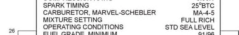
36 LYCOMING OPERATOR S MANUAL SECTION 3 OPERATING INSTRUCTIONS 9.ENGINE FLIGHT CHART (CONT.) Oil Sump Capacity (Cont.) IO-540 MODELS All Series Except Below...12 U.S. Qts. (Minimum safe quantity in sump) /4 U.S. Qts. IO-540-AB1A5, -T4A5D, -T4B5, -T4B5D, -V4A5D, -W1A5, -W1A5D, -W3A5D...8 U.S. Qts. IO-540-T4C5D... 8 U.S. Qts. (10 U.S. Qts. Max.) IO-540-AC1A U.S. Qts. (Minimum safe quantity in sump)...2 U.S. Qts. (Minimum safe quantity in sump - -AB1A5, -AC1A5)...4 U.S. Qts. Oil Pressure, psi Max. Min. Idling Start and Warm-Up Normal Operation All Models Oil Temperature: The maximum permissible oil temperature is 245 F (118 C). For maximum engine life, desired oil temperature should be maintained between 165 F (73.8 C) and 200 F (93.3 C) in level flight cruise conditions. OPERATING CONDITIONS FUEL PRESSURE (PSI) MIN. MAX. IDLE MIN. O-540 Series (Except L3C5D) L3C5D* * - Above compressor outlet pressure. IO-540-AB1A5, -C1B5, -C1C5, -C4B5, -C4B5D, -C4D5, -C4D5D, -D4A5, -D4B5, -N1A5, -T4A5D, -T4B5, -T4B5D, -T4C5D, -V4A5D, -W1A5, -W1A5D, -W3A5D Inlet to fuel pump Inlet to fuel injector IO-540-K1G5, -K1H5 Inlet to fuel pump Inlet to fuel injector IO-540-L1B5D Inlet to fuel pump Inlet to fuel injector IO-540-L1C5 Inlet to fuel pump Inlet to fuel injector IO-540-M1A5, -M1C5 Inlet to fuel pump Inlet to fuel injector
37 SECTION 3 OPERATING INSTRUCTIONS OPERATING CONDITIONS (CONT.) LYCOMING OPERATOR S MANUAL FUEL PRESSURE (PSI) MIN. MAX. IDLE MIN. IO-540-A1A5, -B1A5, -B1C5, -E1A5, -E1B5, -G1A5, -G1E5, -G1F5, -K1C5, -K1E5, -K1E5D Inlet to fuel injector IO-540-AA1A5, -AA1B5 Inlet to fuel pump Inlet to fuel injector IO-540-AC1A5 Inlet to fuel pump Inlet to fuel injector IO-540-AE1A5 Inlet to fuel pump Inlet to fuel injector NOTE All IO-540 models listed have 55 psi maximum to fuel pump inlet with the fuel injector in idle cut-off. Fuel Max. *Max. Cons. Oil Cons. Cyl. Head Operation RPM HP Gal./Hr. Qts./Hr. Temp. O-540-A Series Normal Rated F (260 C) Performance Cruise (75% Rated) F (260 C) Economy Cruise (60% Rated) F (260 C) O-540-B Series Normal Rated F (260 C) Performance Cruise (75% Rated) F (260 C) Economy Cruise (60% Rated) F (260 C) O-540-E, -G, -H Normal Rated F (260 C) Performance Cruise (75% Rated) F (260 C) Economy Cruise (60% Rated) F (260 C) * - At Bayonet Location For maximum service life of the engine maintain cylinder head temperature between 150 F and 435 F during continuous operation. 3-10
38 LYCOMING OPERATOR S MANUAL SECTION 3 OPERATING INSTRUCTIONS OPERATING CONDITIONS (CONT.) Fuel Max. *Max. Cons. Oil Cons. Cyl. Head Operation RPM HP Gal/Hr. Qts./Hr. Temp. O-540-F Series Normal Rated F (260 C) Performance Cruise (75% Rated) F (260 C) Economy Cruise (60% Rated) F (260 C) O-540-J Series** Normal Rated F (260 C) Performance Cruise (75% Rated) F (260 C) Economy Cruise (60% Rated) F (260 C) O-540-L3C5D*** Normal Rated F (260 C) Performance Cruise (75% Rated) F (260 C) Economy Cruise (60% Rated) F (260 C) * - At Bayonet Location For maximum service life of the engine maintain cylinder head temperature between 150 F and 435 F during continuous operation. ** - Model O-540-J Engines Manual leaning to best economy is permitted at cruise conditions up to 75% power resulting in a BSFC of.430 lbs./bhp./hr. Minimum allowable BSFC at take-off and climb conditions is.500 lbs./bhp./hr. ** - Model O-540-J3A5D Engines Manual leaning is permitted at cruise conditions up to 85% power resulting in a BSFC of.420 lbs./bhp./hr. at best economy and.460 lbs./bhp./hr. at best power. Minimum allowable BSFC at take-off and climb conditions is.500 lbs./bhp./hr. *** - Model O-540-L Engines Manual leaning at best economy is permitted at cruise conditions up to 75% power resulting in a BSFC of.430 lbs./bhp./hr. Minimum allowable BSFC at take-off and climb is.550 lbs./bhp./hr. 3-11
39 SECTION 3 OPERATING INSTRUCTIONS LYCOMING OPERATOR S MANUAL OPERATING CONDITIONS (CONT.) Fuel Max. *Max. Cons. Oil Cons. Cyl. Head Operation RPM HP Gal./Hr. Qts./Hr. Temp. IO-540-A, -B, -E, -G, -P Series Normal Rated F (260 C) Performance Cruise (75% Rated) F (260 C) Economy Cruise (60% Rated) F (260 C) IO-540-C, -J Series** Normal Rated F (260 C) Performance Cruise (75% Rated) F (260 C) Economy Cruise (60% Rated) F (260 C) IO-540-D, -N, -R, -T, -V Series Normal Rated F (260 C) Performance Cruise (75% Rated) F (260 C) Economy Cruise (60% Rated) F (260 C) IO-540-K, -L, -M, -S Series Normal Rated F (260 C) Performance Cruise (75% Rated) F (260 C) Economy Cruise (60% Rated) F (260 C) IO-540-W Series Normal Rated F (260 C) Performance Cruise (75% Rated) F (260 C) Economy Cruise (60% Rated) F (260 C) * - At Bayonet Location For maximum service life of the engine maintain cylinder head temperatures between 150 F and 435 F during continuous operation. ** - Limiting manifold pressure for continuous operation of IO-540-C4B5, -C4C5, -J4A5 with Hartzell propeller HCE2Y type hub and R blades. Do not exceed 27 inches manifold pressure below 2300 RPM. 3-12
40 LYCOMING OPERATOR S MANUAL SECTION 3 OPERATING INSTRUCTIONS OPERATING CONDIITONS (CONT.) Fuel Max. *Max. Cons. Oil Cons. Cyl. Head Operation RPM HP Gal./Hr. Qts./Hr. Temp. IO-540-AA Series Normal Rated F (260 C) Performance Cruise (75% Rated) F (260 C) Economy Cruise (60% Rated) F (260 C) IO-540-AB Series Normal Rated F (260 C) Performance Cruise (75% Rated) F (260 C Economy Cruise (60% Rated) F (260 C) IO-540-AC Series Normal Rated F (260 C) Performance Cruise (75% Rated) F (260 C) Economy Cruise (60% Rated) F (260 C) IO-540-AE Series Normal Rated F (260 C) Performance Cruise (75% Rated) F (260 C) Economy Cruise (65% Rated) F (260 C) * - At Bayonet Location For maximum service life of the engine maintain cylinder head temperatures between 150 F and 435 F during continuous operation. e. Engine Shut Down (1) Set propeller at minimum blade angle. (2) Idle until there is a decided decrease in cylinder head temperature. (3) Move mixture control to Idle Cut-Off. (4) When engine stops, turn ignition switch off. 3-13
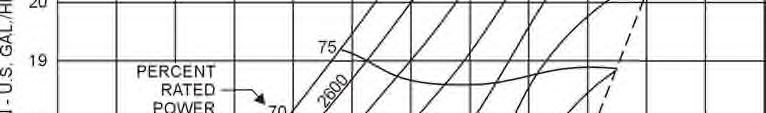
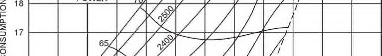
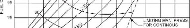
41 SECTION 3 OPERATING INSTRUCTIONS LYCOMING OPERATOR S MANUAL Figure 3-2. Part Throttle Fuel Consumption Curve O-540-A 3-14
42 LYCOMING OPERATOR S MANUAL SECTION 3 OPERATING INSTRUCTIONS Figure 3-3. Sea Level Power Curve O-540-A 3-15
43 SECTION 3 OPERATING INSTRUCTIONS LYCOMING OPERATOR S MANUAL O-540, IO-540 SEREIS Figure 3-4. Sea Level and Altitude Performance Curve O-540-A 3-16
44 LYCOMING OPERATOR S MANUAL SECTION 3 OPERATING INSTRUCTIONS Figure 3-5. Part Throttle Fuel Consumption Curve O-540-B 3-17


45 SECTION 3 OPERATING INSTRUCTIONS LYCOMING OPERATOR S MANUAL Figure 3-6. Sea Level Power Curve O-540-B 3-18


46 LYCOMING OPERATOR S MANUAL SECTION 3 OPERATING INSTRUCTIONS Figure 3-7. Sea Level and Altitude Performance Curve O-540-B 3-19

47 SECTION 3 OPERATING INSTRUCTIONS LYCOMING OPERATOR S MANUAL Figure 3-8. Part Throttle Fuel Consumption Curve O-540-E, -G, -H 3-20
48 LYCOMING OPERATOR S MANUAL SECTION 3 OPERATING INSTRUCTIONS Figure 3-9. Sea Level and Altitude Performance Curve O-540-E, -G, -H 3-21
49 SECTION 3 OPERATING INSTRUCTIONS LYCOMING OPERATOR S MANUAL Figure Part Throttle Fuel Consumption Curve O-540-F Series 3-22


50 LYCOMING OPERATOR S MANUAL SECTION 3 OPERATING INSTRUCTIONS Figure Sea Level and Altitude Performance Curve O-540-F Series 3-23
51 SECTION 3 OPERATING INSTRUCTIONS LYCOMING OPERATOR S MANUAL Figure Sea Level and Altitude Performance Curve O-540-J, -L 3-24


52 LYCOMING OPERATOR S MANUAL SECTION 3 OPERATING INSTRUCTIONS Figure Part Throttle Fuel Consumption IO-540-A, -B, -E, -G, -P 3-25


53 SECTION 3 OPERATING INSTRUCTIONS LYCOMING OPERATOR S MANUAL Figure Sea Level and Altitude Performance Curve IO-540-A, -G, -P 3-26


54 LYCOMING OPERATOR S MANUAL SECTION 3 OPERATING INSTRUCTIONS Figure Sea Level and Altitude Performance Curve IO-540-B, -E 3-27


55 SECTION 3 OPERATING INSTRUCTIONS LYCOMING OPERATOR S MANUAL Figure Part Throttle Fuel Consumption Curve IO-540-C 3-28


56 LYCOMING OPERATOR S MANUAL SECTION 3 OPERATING INSTRUCTIONS Figure Sea Level and Altitude Performance Curve IO-540-C 3-29


57 SECTION 3 OPERATING INSTRUCTIONS LYCOMING OPERATOR S MANUAL Figure Part Throttle Fuel Consumption Curve IO-540-D, -N, -R, -T, -V 3-30


58 LYCOMING OPERATOR S MANUAL SECTION 3 OPERATING INSTRUCTIONS Figure Sea Level and Altitude Performance Curve IO-540-D, -N, -R, -T, -V 3-31


59 SECTION 3 OPERATING INSTRUCTIONS LYCOMING OPERATOR S MANUAL Figure Normally Aspirated Fuel Consumption Curve IO-540-J 3-32
60 LYCOMING OPERATOR S MANUAL SECTION 3 OPERATING INSTRUCTIONS Figure Sea Level and Altitude Performance Curve IO-540-J 3-33
61 SECTION 3 OPERATING INSTRUCTIONS LYCOMING OPERATOR S MANUAL Figure Part Throttle Fuel Consumption Curve IO-540-K, -L, -M, -S 3-34
62 LYCOMING OPERATOR S MANUAL SECTION 3 OPERATING INSTRUCTIONS Figure Sea Level and Altitude Performance Curve IO-540-K, -L, -M, -S 3-35
63 SECTION 3 OPERATING INSTRUCTIONS LYCOMING OPERATOR S MANUAL Figure Fuel Flow vs Percent Rated Power Curve IO-540-W Series 3-36
64 LYCOMING OPERATOR S MANUAL SECTION 3 OPERATING INSTRUCTIONS Figure Sea Level and Altitude Performance Curve IO-540-W Series 3-37
65 SECTION 3 OPERATING INSTRUCTIONS LYCOMING OPERATOR S MANUAL Figure Fuel Flow vs Percent Rated Power IO-540-AA1A5 3-38


66 LYCOMING OPERATOR S MANUAL SECTION 3 OPERATING INSTRUCTIONS Figure Sea Level and Altitude Performance Curve IO-540-AA1A5 3-39


67 SECTION 3 OPERATING INSTRUCTIONS LYCOMING OPERATOR S MANUAL Figure Sea Level and Altitude Performance Curve IO-540-AB Series 3-40
68 LYCOMING OPERATOR S MANUAL SECTION 3 OPERATING INSTRUCTIONS Figure Fuel Flow vs Percent Rated Power IO-540-AC Series 3-41


69 SECTION 3 OPERATING INSTRUCTIONS LYCOMING OPERATOR S MANUAL Figure Sea Level and Altitude Performance Curve IO-540-AC Series 3-42
70 LYCOMING OPERATOR S MANUAL SECTION 3 OPERATING INSTRUCTIONS Figure Fuel Flow vs Percent Rated Power IO-540-AE Series 3-43


71 SECTION 3 OPERATING INSTRUCTIONS LYCOMING OPERATOR S MANUAL O-540, IO-540 SEIES Sea Level and Altitude Performance Curve IO-540-AE Series 3-44
72 LYCOMING OPERATOR S MANUAL SECTION 4 PERIODIC INSPECTIONS Page General Pre-Starting Inspection Daily Pre-Flight Inspection Hour Inspection Hour Inspection Hour Inspection Hour Inspection Hour Inspection Non-Scheduled Inspections
73 This Page Intentionally Left Blank
74 LYCOMING OPERATOR S MANUAL SECTION 4 PERIODIC INSPECTIONS SECTION 4 PERIODIC INSPECTIONS NOTE Perhaps no other factor is quite so important to safety and durability of the aircraft and its components as faithful and diligent attention to regular checks for minor troubles and prompt repair when they are found. The operator should bear in mind that the items listed in the following pages do not constitute a complete aircraft inspection, but are meant for the engine only. Consult the airframe manufacturer s handbook for additional instructions. Pre-Starting Inspection The daily pre-flight inspection is a check of the aircraft prior to the first flight of the day. This inspection is to determine the general condition of the aircraft and engine. The importance of proper pre-flight inspection cannot be over emphasized. Statistics prove several hundred accidents occur yearly directly responsible to poor pre-flight. Among the major causes of poor pre-flight inspection are lack of concentration, reluctance to acknowledge the need for a check list, carelessness bred by familiarity and haste. 4-1
75 SECTION 4 PERIODIC INSPECTIONS LYCOMING OPERATOR S MANUAL 1. DAILY PRE-FLIGHT (ENGINE). a. Be sure all switches are in the Off position. b. Be sure magneto ground wires are connected. c. Check oil level. d. Check fuel level. e. Check fuel and oil line connections, note minor indications for repair at 50-hour inspection. Repair any leaks before aircraft is flown. f. Open the fuel drain to remove any accumulation of water and sediment. g. Make sure all shields and cowling are in place and secure. If any are missing or damaged, repair or replacement should be made before the aircraft is flown. h. Check controls for general condition, travel and freedom of operation. i. Induction system air filter should be inspected and serviced in accordance with the airframe manufacturer s recommendations HOUR INSPECTION (ENGINE). After the first ten (10) hours of operating time, new, rebuilt, or newly overhauled engines replace the oil filter, and conduct an inspection of the contents of the used oil filter for traces of metal particles HOUR INSPECTION (ENGINE). At twenty-five (25) hours of operating time since the first inspection, new, rebuilt, or newly overhauled engines should undergo a 50-hour inspection including draining and renewing lubricating oil, replacing the oil filter, and inspecting the contents of the used oil filter. NOTE If the engine does not have a full-flow oil filter, change oil every 25 hours; also, inspect oil pressure and suction screens for metal contamination, and clean thoroughly before reinstallation HOUR INSPECTION (ENGINE). In addition to the items listed for daily pre-flight inspection, the following maintenance checks should be made after every 50 hours of operation. 4-2 a. Ignition System (1) If fouling of spark plugs has been apparent, clean them and check electrode gap. Rotate bottom plugs to upper position. (2) Examine spark plug leads of cable and ceramics for corrosion and deposits. This condition is evidence of either leaking spark plugs, improper cleaning of the spark plug walls or connector ends. Where this condition is found, clean the cable ends, spark plug walls and ceramics with a dry, clean cloth or a clean cloth moistened with methyl-ethyl-ketone. All parts should be clean and dry before reassembly. (3) Check ignition harness for security of mounting clamps and be sure connections are tight at spark plug and magneto terminals.
76 LYCOMING OPERATOR S MANUAL SECTION 4 PERIODIC INSPECTIONS b. Fuel Line and Induction System Check the primer lines for leaks and security of the clamps. Remove and clean the fuel inlet strainers. Check the mixture control and throttle linkage for travel, freedom of movement, security of the clamps and lubricate if necessary. Check the air intake ducts for leaks, security, filter damage; evidence of dust or other solid material in the ducts is indicative of inadequate filter care or damaged filter. Check vent lines for evidence of fuel or oil seepage; if present, fuel pump may require replacement. c. Lubrication System (1) Check oil lines for leaks, particularly at connections; for security of anchorage and for wear due to rubbing or vibration, for dents and cracks. (2) Replace elements on external full-flow oil filters. Before disposing of used element check interior folds for traces of metal particles that might be evidence of internal engine damage. Drain and renew lubricating oil. (Reference latest revision of Service Instruction No for proper oil.) d. Exhaust System Check attaching flanges at exhaust ports on cylinders for evidence of leakage. If they are loose, they must be removed and machined flat before they are reassembled and tightened. Examine exhaust manifolds for general condition. e. Cooling System Check cowling, baffles and baffle seals for damage and secure anchorage. Any damaged or missing part of the cooling system must be repaired or replaced before the aircraft resumes operation. f. Cylinders Check rocker box covers for evidence of oil leaks. If found, replace gasket and tighten screws to specified torque (50 in.-lbs.). Check cylinders for evidence of excessive heat which is indicated by burned paint on the cylinder. This condition is indicative of internal damage to the cylinder and, if found, its cause must be determined and corrected before the aircraft resumes operation. Heavy discoloration and appearance of seepage at cylinder head and barrel attachment area is usually due to emission of thread lubricant used during assembly of the barrel at the factory, or by slight gas leakage which stops after the cylinder has been in service for awhile. This condition is neither harmful not detrimental to engine performance and operation. If it can be proven that leakage exceeds these conditions, the cylinder should be replaced HOUR INSPECTION. In addition to the items listed for daily pre-flight, and 50-hour inspection, the following maintenance checks should be made after every one hundred hours of operation. a. Electrical System (1) Check all wiring connected to the engine or accessories. Any shielded cables that are damaged should be replaced. Replace clamps or loose wires and check terminals for security and cleanliness. (2) Remove spark plugs; test, clean, regap, and rotate them. Replace if necessary. 4-3
77 SECTION 4 PERIODIC INSPECTIONS LYCOMING OPERATOR S MANUAL b. Lubrication System Drain and renew lubricating oil. c. Magnetos Check breaker points for pitting and minimum gap. Check for excessive oil in the breaker compartment, if found, wipe dry with a clean lintless cloth. The felt located at the breaker points should be lubricated in accordance with the magneto manufacturer s instructions. Check magneto to engine timing. (Timing procedures for Bendix and Slick magnetos are covered in the Maintenance Procedures Section.) d. Engine Accessories Engine mounted accessories such as pumps, temperature and pressure sensing units should be checked for secure mounting, tight connections. e. Cylinders Check cylinders visually for cracked or broken fins. f. Engine Mounts Check engine mounting bolts and bushings for security and excessive wear. Replace any excessive wear. Replace any bushings that are excessively worn. g. Primer Nozzles Disconnect primer nozzles from engine and check for equal flow. h. Fuel Injector Nozzles and Lines Check fuel injector nozzles for looseness. Tighten to 60 in.-lbs. torque. Check fuel line for dye stains at connections (indicating leakage) and security of lines. Repair or replacement must be accomplished before aircraft resumes operation. i. Carburetor Check throttle body attaching screws for tightness; the correct torque for these screws is in.-lbs HOUR INSPECTION. In addition to the items listed for daily pre-flight, 50-hour and 100-hour inspections, the following maintenance check should be made after every 400 hours of operation. Valve Inspection Remove rocker box covers and check for freedom of valve rockers when valves are closed. Look for evidence of abnormal wear or broken parts in the area of the valve tips, valve keeper, springs and spring seats. If any indications are found, the cylinder and all of its components should be removed (including the piston and connecting rod assembly) and inspected for further damage. Replace any parts that do not conform with limits shown in the latest revision of Special Service Publication No. SSP NON-SCHEDULED INSPECTIONS. Occasionally, service bulletins or service instructions are issued by Lycoming that require inspection procedures that are not listed in this manual. Such publications, usually are limited to specified engine models and become obsolete after corrective modification has been accomplished. All such publications are available from Lycoming distributors, or from the factory by subscription. Consult the latest revision of Service Letter No. L114 for subscription information. Maintenance facilities should have an up-to-date file of these publications available at all times. 4-4
78 LYCOMING OPERATOR S MANUAL SECTION 5 MAINTENANCE PROCEDURES Page General Ignition and Electrical System Ignition Harness and Wire Replacement Timing Magneto to Engine Generator or Alternator Output Fuel System Repair of Fuel Leaks Carburetor or Fuel Injector Inlet Screen Assembly Fuel Grades and Limitations Air Intake Ducts and Filter Idle Speed and Mixture Adjustment Lubrication System Oil Grades and Limitations Oil Suction and Oil Pressure Screens Oil Relief Valve Cylinders Generator or Alternator Drive Belt Tension
79 This Page Intentionally Left Blank
80 LYCOMING OPERATOR S MANUAL SECTION 5 MAINTENANCE PROCEDURES SECTION 5 MAINTENANCE PROCEDURES The procedures described in this section are provided to guide and instruct personnel in performing such maintenance operations that may be required in conjunction with the periodic inspections listed in the preceding section. No attempt is made to include repair and replacement operations that will be found in the applicable Lycoming Overhaul Manual. 1. IGNITION AND ELECTRICAL SYSTEM. a. Ignition Harness and Wire Replacement In the event that an ignition harness or an individual lead is to be replaced, consult the wiring diagram to be sure harness is correctly installed. Mark location of clamps and clips to be certain the replacement is clamped at correct locations. b. Timing Magnetos to Engine (Bendix) (1) Remove a spark plug from No. 1 cylinder and place a thumb over the spark plug hole. Rotate the crankshaft in direction of normal rotation until the compression stroke is reached, which is indicated by a positive pressure inside the cylinder tending to push the thumb off the spark plug hole. Continue rotating the crankshaft until the advance timing mark on the front face of the starter ring gear is in alignment with the small hole located at the two o clock position on the front face of the starter housing. (Refer to Specification chapter or to engine nameplate for designated number of degrees of spark advance.) At this point, the engine is ready for assembly of the magnetos. (2) Single Magneto Remove the inspection plugs from both magnetos and turn the drive shaft in direction of normal rotation until (-20 and -200 series) the first painted chamfered tooth on the distributor gear is aligned in the center of the inspection window (-1200 series) the applicable timing mark on the distributor gear is approximately aligned with the mark on the distributor block. See Figure 5-2. Being sure the gear does not move from this position, install gaskets and magnetos on the engine. Note that an adapter is used with all magnetos. Secure with (clamps on series) washers and nuts; tighten only finger tight. (3) Using a battery-powered timing light, attach the positive lead to a suitable terminal connected to the switch terminal of the magneto and the negative lead to any unpainted portion of the engine. Rotate the magneto in its mounting flange to a point where the light comes on, then slowly turn it in the opposite direction until the light goes out. Bring the magneto back slowly until the light just comes on. Repeat this with the second magneto. (4) Back off the crankshaft a few degrees; the timing light should go out. Bring the crankshaft slowly back in direction of normal rotation until the timing mark and the hole in the starter housing are in alignment. At this point, both lights should go on simultaneously. Tighten nuts to specified torque. (5) Dual Magnetos Place the engine in the No. 1 advance firing position as directed in paragraph 1b(1). (6) Install the magneto-to-engine gasket on the mounting flange. 5-1
81 SECTION 5 MAINTENANCE PROCEDURES LYCOMING OPERATOR S MANUAL Figure 5-1. Ignition Wiring Diagram Figure 5-2. Timing Marks 6 Cylinder 1200 Series 5-2
82 LYCOMING OPERATOR S MANUAL SECTION 5 MAINTENANCE PROCEDURES WARNING DO NOT ATTACH HARNESS SPARK PLUG ENDS TO THE SPARK PLUGS UNTIL ALL MAGNETO-TO-ENGINE TIMING PROCEDURES AND MAGNETO-TO-SWITCH CONNECTIONS ARE ENTIRELY COMPLETED. (7) To remove engine-to-magneto drive gear train backlash, turn engine magneto drive as far as possible in direction opposite to normal rotation; then return in the direction of normal rotation to timing mark on starter support. (8) Remove the timing window plug from the most convenient side of the magneto housing and the plug from the rotor viewing location in the center of the housing. (9) Turn the rotating magnet drive shaft in the normal direction of magneto rotation until the painted tooth of the large distributor gear is centered in the timing hole. (10) Observe that at this time the built in pointer just ahead of the rotor viewing window aligns with the R or L mark on the rotor depending on whether the magneto is of right or left hand rotation as specified on the magneto nameplate. (11) Hold the magneto in its No. 1 firing position (tooth in window center and pointer over R or L mark on rotor) and install magneto to the engine and loosely clamp in position. (12) Attach red lead from the timing light to left switch adapter lead, green lead of timing light to right switch adapter lead and the black lead of the light to magneto housing. (13) Turn the entire magneto in direction of rotor rotation until the red timing light comes on. (14) Rotate the magneto in the opposite direction until the red light just goes off indicating left main breaker has opened. Then evenly tighten the magneto mounting clamps. (15) Back the engine up approximately 10 and then carefully bump the engine forward at the same time observing the timing lights. (16) At the No. 1 firing position of the engine, the red light should go off indicating left main bearing opening. The right main breaker, monitored by the green light, must open within ± 2 engine degrees of the No. 1 firing position. (17) Repeat steps (13) thru (15) until the condition described in paragraph (16) is obtained. (18) Complete tightening of the magneto securing clamps by torquing to 150 in.-lbs. (19) Recheck timing once more and if satisfactory disconnect timing light. Remove adapter leads. (20) Reinstall plugs in timing inspection holes and torque to in.-lbs. 5-3
83 SECTION 5 MAINTENANCE PROCEDURES LYCOMING OPERATOR S MANUAL Figure 5-3. Ignition Wiring Diagram Dual Magneto 5-4
84 LYCOMING OPERATOR S MANUAL SECTION 5 MAINTENANCE PROCEDURES c. Timing Magnetos to Engine (Slick) (1) Remove a spark plug from No. 1 cylinder and place a thumb over the spark plug hole. Rotate the crankshaft in direction of normal rotation until the compression stroke is reached; this is indicated by a positive pressure inside the cylinder tending to push the thumb off the spark plug hole. Continue rotating the crankshaft until the advance timing mark on the front face of the starter ring gear is in alignment with the small hole located at the two o clock position on the front face of the starter housing. (Refer to Specification chapter or to engine nameplate for designated number of degrees of spark advance.) At this point, the engine is ready for assembly of the magnetos. (2) Remove the ignition harness from the left (retard breaker) magneto, if installed. Insert the Slick T- 118 timing pin in the hole marked L on the face of the distributor block. Apply a slight inward pressure to the pin and slowly rotate the magneto drive shaft clockwise until the shoulder of the pin seats against the distributor block. When properly engaged, the timing pin will be inserted 7/8 inch into the distributor block. NOTE If the magneto shaft cannot be rotated and if the timing pin is not seated 7/8 inch into the distributor block, remove the pin, rotate the drive shaft 1/8 turn and repeat the insertion procedure. CAUTION DO NOT ROTATE THE MAGNETO ROTOR SHAFT WITH THE TIMING PIN INSERTED INTO THE DISTRIBUTOR BLOCK. THIS COULD DAMAGE THE INTERNAL COMPONENTS OF THE MAGNETO. (3) Inspect the left magneto accessory housing mounting pad to ensure that magneto drive dampers, adapter, and gaskets are there and installed properly. Position the magneto on its side with the top of the magneto located outboard away from the accessory housing vertical centerline. Install the magneto onto the mounting pad. Be sure the drive dampers remain in place when the magneto drive is inserted into the drive gear. Secure the magneto to the accessory housing with the proper clamps, washers, and nuts. Tighten nuts only finger tight. CAUTION DO NOT ROTATE THE MAGNETO OR ENGINE WITH THE TIMING PIN INSERTED INTO THE MAGNETO DISTRIBUTOR BLOCK. THIS COULD CAUSE DAMAGE TO THE INTERNAL COMPONENTS OF THE MAGNETO. (4) Remove the timing pin from the distributor block. (5) Repeat steps (2), (3), (4) for the right (plain) magneto. WARNING DO NOT ATTACH HARNESS SPARK PLUG ENDS TO THE SPARK PLUGS UNTIL ALL MAGNETO-TO-ENGINE TIMING PROCEDURES AND MAGNETO-TO-SWITCH CONNECTIONS ARE ENTIRELY COMPLETED. 5-5
85 SECTION 5 MAINTENANCE PROCEDURES LYCOMING OPERATOR S MANUAL (6) Attach a timing light to the magneto condenser stud according to the timing light manufacturer s instructions. (7) Rotate the magneto assembly in the direction of rotor rotation until the timing light comes on. If the light is on initially, rotation of the magneto is not required. This indicates the breaker points are closed. (8) Slowly rotate the magneto assembly in the opposite direction, until the light goes out or the breaker points open. (9) Alternately tighten the magneto mounting nut clamps to 8 ft.-lbs. torque. Continue to tighten both nuts alternately, in several steps, to 17 ft.-lbs. torque. (10) Repeat steps (6) thru (9) for the second magneto. (11) Rotate the engine approximately 10 opposite to the normal rotational direction. The timing lights should light. Slowly (bump) rotate the engine in the normal direction until the timing lights go out. Both lights should go out within ± 1 of the designated timing mark on ring gear with the dot on the starter housing as referenced in step (1). (12) Repeat steps (6) thru (10) until the condition described in step (11) is satisfied. (13) If the magneto position (± 15 from the mounting pad horizontal centerline allowed) interference is encountered, which is unlikely, the magneto must be removed and the drive gear in the accessory housing repositioned. Care must be taken not to drop the dampers into the engine during the repositioning of the drive gear. (14) Remove timing light leads from the magnetos. (15) Attach the appropriate switch or P-Leads to the condenser terminal of each magneto using a lockwasher and nut. Torque nut to in.-lbs. (16) Retard Breaker Attach one positive lead of the timing light to retard breaker terminal and the negative lead to ground. Set the engine required number of degrees before top center on the compression stroke of the number 1 cylinder. The timing light should be on, indicating the retard breaker points are closed. Slowly rotate the engine in the normal direction until the timing light goes out indicating the points opened. The TC #1 timing mark on the ring gear should be aligned with the dot on the starter housing within ± 3. If the timing of these points is incorrect, refer to the Slick Maintenance Manual for the procedure and proper adjustment of the contact points. (17) Attach the switch retard breaker lead to the retard post on the magneto (left magneto only) using a lockwasher and nut. Torque nut to in.-lbs. (18) Install ignition harness assemblies on the magnetos. The left magneto harness is marked left and the right magneto harness is marked right. Check for proper installation of the O ring seal in the wire cap. Torque cap-mounting screws to in.-lbs. 5-6
86 LYCOMING OPERATOR S MANUAL SECTION 5 MAINTENANCE PROCEDURES NOTE Some timing lights operate in the reverse manner as described. The light comes on when the breaker points open. Check your timing light instructions. c. Generator or Alternator Output Check the generator or alternator (whichever is applicable) to determine that the specified voltage and current are being obtained. 2. FUEL SYSTEM. a. Repair of Fuel Leaks In the event a line or fitting in the fuel system is replaced, use only a fuelsoluble lubricant, such as Loctite Hydraulic Sealant. Do not use Teflon tape or any other form of thread compound. Do not apply sealant to the first two threads. b. Carburetor or Fuel Injector Inlet Screen Assembly Remove the assembly and check the screen for distortion or openings in the strainer. Replace for either of these conditions. Clean screen assembly in solvent and dry with compressed air. To install the screen assembly, place the gasket on the screen assembly and install the assembly in the throttle body and tighten to inch pounds torque for carburetor or inch pounds torque for fuel injector. c. Fuel Grades and Limitations See recommended fuel grades in Section 3, or reference latest revision of Service Instruction No In the event that the specified fuel is not available at some locations, it is permissible to use higher octane fuel. Fuel of a lower octane than specified is not to be used. Do not use automotive fuel regardless of octane rating. NOTE Refer to the latest revision of Service Instruction No regarding specified fuel for Lycoming engines. d. Air Intake Ducts and Filter Check all air intake ducts for dirt or restrictions. Inspect and service air filters as instructed in the airframe manufacturer s handbook. e. Idle Speed and Mixture Adjustment (1) Start the engine and warm up in the usual manner until oil and cylinder head temperatures are normal. (2) Check magnetos. If the mag-drop is normal (refer to Section 3.6), proceed with idle adjustment. (3) Set throttle stop screw so that the engine idles at the aircraft manufacturer s recommended idling RPM. If the RPM changes appreciably after making idle mixture adjustment during the succeeding steps, readjust the idle speed to the desired RPM Revised March
87 SECTION 5 MAINTENANCE PROCEDURES LYCOMING OPERATOR S MANUAL (4) When the idling speed has been stabilized, move the cockpit mixture control lever with a very slow, steady pull toward the Idle Cut-Off position and observe the tachometer for any change during the leaning process. Caution must be exercised to return the mixture control to the Full Rich position before the RPM can drop to a point where the engine cuts out. An increase of more than 35 RPM while leaning out indicates an excessively rich idle mixture. An immediate decrease in RPM (if not preceded by a momentary increase) indicates the idle mixture is too lean. If the above indicates that the idle adjustment is too rich or too lean, turn the idle mixture adjustment in the direction required for correction, and check this new position by repeating the above procedure. Make additional adjustments as necessary until a check results in a momentary pickup of approximately 10 to 25 RPM. Each time the adjustment is changed, the engine should be run up to 2000 RPM to clear the engine before proceeding with the RPM check. Make final adjustment of the idle speed adjustment to obtain the desired idling RPM with closed throttle. The above method aims at a setting that will obtain maximum RPM with minimum manifold pressure. In case the setting does not remain stable, check the idle linkage; any looseness in this linkage would cause erratic idling. In all cases, allowance should be made for the effect of weather conditions and field altitude upon idling adjustment. 3. LUBRICATION SYSTEM. 5-8 a. Oil Grades and Limitations Service the engine in accordance with the recommendations shown in Section 3. b. Oil Suction and Oil Pressure Screens At each fifty hours inspection remove, inspect for metal particles, clean and reinstall. NOTE If an engine does not have a full-flow oil filter, change oil every 25 hours; also, inspect oil pressure and suction screens for metal contamination, and clean thoroughly before reinstallation. c. Oil Relief Valve (Non-Adjustable) The function of the oil pressure relief valve is to maintain engine oil pressure within specified limits. The valve, although not adjustable, may be controlled by the addition of a maximum of nine STD-425 washers under the cap to increase pressure or the use of a spacer (Lycoming P/N or 73630) to decrease pressure. A modification on later models has eliminated the need for the spacers. Particles of metal or other foreign matter lodged between the ball and seat will result in faulty readings. It is advisable, therefore, to disassemble, inspect and clean the valve if excessive pressure fluctuations are noted. d. Oil Relief Valve (Adjustable) The adjustable oil relief valve enables the operator to maintain engine oil pressure within the specified limits. If the pressure under normal operating conditions should consistently exceed the maximum or minimum specified limits, adjust the valve as follows. With the engine warmed up and running at approximately 2000 RPM, observe the reading on the oil pressure gage. If the pressure is above maximum or below minimum specified limits, stop engine and screw the adjusting screw out to decrease pressure and in to increase pressure. Depending on installation, the adjusting screw may have only a screw driver slot; or it may have the screw driver slot plus a pinned castellated nut and may be turned with either a screw driver or a box wrench.
88 LYCOMING OPERATOR S MANUAL SECTION 5 MAINTENANCE PROCEDURES NOTE Check applicable parts catalog for optional size/pressure capacity relief- valve springs. 4. CYLINDERS. It is recommended that as a field operation, cylinder maintenance be confined to replacement of the entire assembly. For valve replacement consult the proper overhaul manual. This should be undertaken only as an emergency measure. a. Removal of Cylinder Assembly (1) Remove exhaust manifold and cooling baffles. (2) Remove rocker box drain tube, intake pipe, baffle and any clips that might interfere with the removal of the cylinder. (3) Disconnect ignition cables and remove the bottom spark plug. (4) Remove rocker box cover and rotate crankshaft until piston is approximately at top center of the compression stroke. This is indicated by a positive pressure inside of cylinder tending to push thumb off of bottom spark plug hole. (5) Slide valve rocker shafts from cylinder head and remove the valve rockers. Valve rocker shafts can be removed after the cylinder is removed from the engine. Remove rotator cap from exhaust valve stem. (6) Remove push rods by grasping ball end and pulling rod out of shroud tube. Detach shroud tube spring and lock plate and pull shroud tubes through holes in cylinder head. NOTE The hydraulic tappets, push rods, rocker arms and valves must be assembled in the same location from which they were removed. (7) Remove cylinder base nuts and hold down plugs (where employed), then remove cylinder by pulling directly away from crankcase. Be careful not to allow the piston to drop against the crankcase as the piston leaves the cylinder. b. Removal of Piston from Connecting Rod Remove the piston pin plugs. Insert piston pin puller (P/N 64843) through piston pin, assemble puller nut; then proceed to remove piston pin. Do not allow connecting rod to rest on the cylinder bore of the crankcase. Support the connecting rod with heavy rubber band, discarded cylinder base oil ring seal, or any other non-marring method. c. Removal of Hydraulic Tappet Sockets and Plunger Assemblies It will be necessary to remove and bleed the hydraulic tappet plunger assembly so that dry tappet clearance can be checked when the cylinder assembly is reinstalled. This is accomplished in the following manner: (1) Remove the hydraulic tappet push rod socket by inserting the forefinger into the concave end of the socket and withdrawing. If the socket cannot be removed in this manner, it may be removed by grasping the edge of the socket with a pair of needle nose pliers. However, care must be exercised to avoid scratching the socket. 5-9
89 SECTION 5 MAINTENANCE PROCEDURES LYCOMING OPERATOR S MANUAL (2) To remove the hydraulic tappet plunger assembly, use the special Lycoming service tool. In the event that the tool is not available, the hydraulic tappet plunger assembly may be removed by a hook in the end of a short piece of lockwire, inserting the wire so that the hook engages the spring of the plunger assembly. Draw the plunger assembly out of the tappet body by gently pulling the wire. CAUTION NEVER USE A MAGNET TO REMOVE HYDRAULIC PLUNGER ASSEMBLIES FROM THE CRANKCASE. THIS CAN CAUSE THE CHECK BALL TO REMAIN OFF ITS SEAT, RENDERING THE UNIT INOPERATIVE. d. Assembly of Hydraulic Tappet Plunger Assemblies To assemble the unit, unseat the ball by inserting a thin clean wire through the oil inlet hole. With the ball off its seat, insert the plunger and twist clockwise so that the spring catches. All oil must be removed before the plunger is inserted. e. Assembly of Cylinder and Related Parts Rotate the crankshaft so that the connecting rod of the cylinder being assembled is at the top center of compression stroke. This can be checked by placing two fingers on the intake and exhaust tappet bodies. Rock crankshaft back and forth over top center. If the tappet bodies do not move, the crankshaft is on the compression stroke Figure 5-4. Location of Shims Between Cylinder Barrel and Hold-Down Plates (where applicable) and Sequence of Tightening Cylinder Base Hold-Down Nuts
90 LYCOMING OPERATOR S MANUAL SECTION 5 MAINTENANCE PROCEDURES (1) Place each plunger assembly in its respective tappet body and assemble the socket on top of plunger assembly. (2) Assemble piston with rings so that the number stamped on the piston pin boss is toward the front of the engine. The piston pin should be of a hand push fit. If difficulty is experienced in inserting the piston pin, it is probably caused by carbon or burrs in the piston pin hole. During assembly, always use a generous quantity of oil, both in the piston pin hole and on the piston pin. (3) Assemble one piston pin plug at each end of the piston pin and place a new rubber oil seal ring around the cylinder skirt. Coat piston and rings and the inside of the cylinder generously with oil. (4) Space piston ring gaps. Then, using a piston ring compressor, assemble the cylinder over the piston so that the intake port is at the bottom of the engine. Push the cylinder all the way on, catching the ring compressor as it is pushed off. NOTE Before installing cylinder hold-down nuts, lubricate crankcase thru-stud threads with any one of the following lubricants, or combinations of lubricants % SAE 50W engine oil and 10% STP. 2. Parker Thread Lube % SAE 30 engine oil and 40% Parker Thread Lube. (5) Assemble hold-down plates (where applicable) and cylinder base hold-down nuts and tighten as directed in the following steps. NOTE At any time a cylinder is replaced, it is necessary to retorque the thru-studs on the cylinder on the opposite side of the engine. (a) (Engines using hold-down plates) Install shims between cylinder base hold-down plates and cylinder barrel, as directed in Figure 5-4, and tighten ½ inch hold-down nuts to 300 in.-lbs. (25 ft.-lbs.) torque, using the sequence shown in Figure 5-4. (b) Remove shims, and using the same sequence, tighten the ½ inch cylinder base nuts to 600 in.- lbs. (50 ft.-lbs.) torque. NOTE Cylinder assemblies not using hold-down plate are tightened in the same manner as above omitting the shims. (c) Tighten the 3/8 inch hold-down nuts to 300 in.-lbs. (25 ft.-lbs.) torque. Sequence of tightening is optional. (d) After completing tightening sequence, recheck final torque value. 5-11
91 SECTION 5 MAINTENANCE PROCEDURES LYCOMING OPERATOR S MANUAL CAUTION AFTER ALL CYLINDER BASE NUTS HAVE BEEN TIGHTENED, REMOVE ANY NICKS IN THE CYLINDER FINS BY FILING OR BURRING. (6) Install new shroud tube oil seals on both ends of shroud tube. Install shroud tube and lock in place as required for type of cylinder. (7) Assemble each push rod in its respective shroud tube. Then place rotator cap over end of exhaust valve stem. Assemble each rocker in its respective position by placing rocker between bosses and by sliding valve rocker shaft in place to retain rocker. (8) Be sure that the piston is at top center of compression stroke and that both valves are closed. Check clearance between the valve stem tip and the valve rocker. In order to check this clearance, place the thumb of one hand on the valve rocker directly over the end of the push rod and push down so as to compress the hydraulic tappet spring. While holding the spring compressed, the valve clearance should be between.028 and.080 inch. If clearance does not come within these limits, remove the push rod and insert a longer or shorter push rod, as required to correct clearance. NOTE Inserting a longer push rod will decrease the valve clearance. (9) Install intercylinder baffles, rocker box covers, intake pipes, rocker box drain tubes and exhaust manifold. 5. GENERATOR OR ALTERNATOR DRIVE BELT TENSION. Check the tension of a new belt 25 hours after installation. Refer to latest revision of Service Instruction No for methods of checking generator or alternator drive belt tension. 5-12
92
93 LYCOMING OPERATOR S MANUAL SECTION 6 TROUBLE-SHOOTING Page Failure of Engine to Start Failure of Engine to Idle Properly Low Power and Uneven Running Failure of Engine to Develop Full Power Rough Engine Low Oil Pressure High Oil Temperature Excessive Oil Consumption High Fuel Flow Indication on Fuel Gage
94 This Page Intentionally Left Blank
95 LYCOMING OPERATOR S MANUAL SECTION 6 TROUBLE-SHOOTING SECTION 6 TROUBLE-SHOOTING Experience has proven that the best method of trouble-shooting is to decide on the various causes of a given trouble and then to eliminate causes one by one, beginning with the most probable. The following charts list some of the more common troubles, which may be encountered in maintaining engines; their probable causes and remedies. 1. TROUBLE-SHOOTING ENGINE. TROUBLE PROBABLE CAUSE REMEDY Failure of Engine to Start Lack of fuel Check if fuel valve is on. Check fuel system for leaks. Fill fuel tank. Clean dirty lines, strainers or fuel valves. Overpriming Defective spark plugs Defective ignition wire Defective battery Improper operation of magneto breaker Lack of sufficient fuel flow Water in fuel injector or carb. Internal failure Leave ignition off and mixture control in Idle Cut-Off, open throttle and unload engine by cranking for a few seconds. Turn ignition switch on and proceed to start in a normal manner. Clean and adjust or replace spark plugs. Check with electric tester, and replace any defective wires. Replace with charged battery. Check mag switch is on. Clean points. Check internal timing of magnetos. Disconnect fuel line and check fuel flow. Drain fuel injector or carburetor and fuel lines. Check oil screens for metal particles. If found, complete overhaul of the engine may be indicated. 6-1
96 SECTION 6 TROUBLE-SHOOTING LYCOMING OPERATOR S MANUAL TROUBLE PROBABLE CAUSE REMEDY Failure of Engine to Idle Properly Low Power and Uneven Running Incorrect idle mixture Leak in induction system Incorrect idle adjustment Uneven cylinder compression Faulty ignition system Insufficient fuel pressure Leak in air bleed nozzle balance line Plugged fuel injector nozzle Flow divider fitting plugged Mixture too rich; indicated by sluggish engine operation, red exhaust flame at night. Extreme cases indicated by black smoke from exhaust Mixture too lean; indicated by overheating or backfiring Leaks in induction system Defective spark plugs Improper fuel Magneto breaker points not working properly Adjust mixture. Tighten all connections in the induction system. Replace any parts that are defective. Adjust throttle stop to obtain correct idle. Check condition of piston rings and valve seats. Check entire ignition system. Adjust fuel pressure. Check connection and replace if necessary. Clean or replace nozzle. Clean fitting. Readjustment of fuel injector or carburetors by authorized personnel is indicated. Check fuel lines for dirt or other restrictions. Readjustment of fuel injector or carburetor by authorized personnel is indicated. Tighten all connections. Replace defective parts. Clean and gap or replace spark plugs. Fill tank with fuel of recommended grade. Clean points. Check internal timing of magnetos. 6-2
97 LYCOMING OPERATOR S MANUAL SECTION 6 TROUBLE-SHOOTING TROUBLE PROBABLE CAUSE REMEDY Low Power and Uneven Running (Cont.) Failure of Engine to Develop Full Power Defective ignition wire Defective spark plug terminal connectors Plugged fuel injector nozzle Leak in induction system Defective tachometer Plugged fuel injector nozzle Throttle lever out of adjustment Improper fuel flow Restriction in air scoop Improper fuel Faulty ignition Check wire with electric tester. Replace defective wire. Replace connectors on spark plug wire. Clean or replace nozzle. Tighten all connections and replace defective parts. Replace tachometer. Clean or replace nozzle. Adjust throttle lever. Check strainer, gage and flow at the fuel line. Examine air scoop and remove restrictions. Drain and refill tank with recommended fuel. Tighten all connections. Check system with tester. Check ignition timing. Rough Engine Cracked engine mount Replace or repair mounting. Defective mounting bushings Uneven compression Plugged fuel injector nozzle Install new mounting bushings. Check compression. Clean or replace nozzle. Low Oil Pressure Insufficient oil Fill sump to proper level with recommended oil. Defective pressure gage Air lock or dirt in relief valve Replace. Remove and clean oil pressure relief valve. 6-3
98 SECTION 6 TROUBLE-SHOOTING LYCOMING OPERATOR S MANUAL TROUBLE PROBABLE CAUSE REMEDY Low Oil Pressure (Cont.) Leak in suction line or pressure line High oil temperature Stoppage in oil pump intake passage Check gasket between accessory housing and crankcase. See High Oil Temperature in Trouble column. Check line for obstruction. Clean suction strainer. High Oil Temperature Insufficient air cooling Check air inlet and outlet for deformation or obstruction. Insufficient oil supply Defective temperature gage Low grade of oil Clogged oil lines or strainers Excessive blow-by Failing or failed bearing Fill oil sump to proper level with specified oil. Replace gage. Replace with oil conforming to specifications. Remove and clean oil strainers. Usually caused by worn or stuck rings. Examine sump for metal particles. If found, overhaul of engine is indicated. Excessive Oil Consumption Low grade of oil Fill tank with oil conforming to specification. High Fuel Flow Indication on Fuel Gage Failing or failed bearings Worn piston rings Incorrect installation of piston rings Failure of rings to seal (new nitrided cylinders) Plugged fuel injector nozzle Check sump for metal particles. Install new rings. Install new rings. Use mineral base oil. Climb to cruise altitude at full power and operate at 75% cruise power setting until oil consumption stabilizes. Clean or replace nozzle. 6-4
99 LYCOMING OPERATOR S MANUAL SECTION 7 INSTALLATION AND STORAGE Page Preparation of Engine for Installation General Inspection of Engine Mounting Attaching Engine to Mounts Oil and Fuel Line Connections Propeller Installation Preparation of Carburetors and Fuel Injectors for Installation Carburetor Fuel Injector Corrosion Prevention in Engines Installed in Inactive Aircraft Installation Drawing
100 This Page Intentionally Left Blank
101 LYCOMING OPERATOR S MANUAL SECTION 7 INSTALLATION AND STORAGE SECTION 7 INSTALLATION AND STORAGE 1. PREPARATION OF ENGINE FOR INSTALLATION. Before installing an engine that has been prepared for storage, remove all dehydrator plugs, bags of desiccant and preservative oil from the engine. Preservative oil can be removed by removing the bottom spark plugs and turning the crankshaft three or four revolutions by hand. The preservative oil will then drain through the spark plug holes. Draining will be facilitated if the engine is tilted from side to side during the above operation. Preservative oil which has accumulated in the sump can be drained by removing the oil sump plug. Engines that have been stored in a cold place should be removed to an environment of at least 70 F (21 C) for a period of 24 hours before preservative oil is drained from the cylinders. If this is not possible, heat the cylinders with heat lamps before attempting to drain the engine. After the oil sump has been drained, the plug should be replaced, safety wired, and the sump refilled with lubricating oil. The crankshaft should again be turned several revolutions to saturate the interior of the engine with the clean oil. When installing spark plugs, make sure that they are clean; if not, wash them in clean petroleum solvent. Of course, there will be a small amount of preservative oil remaining in the engine, but this can cause no harm. However, after twenty-five hours of operation, the lubricating oil should be drained while the engine is hot. This will remove any residual preservative oil that may have been present. CAUTION DO NOT ROTATE THE CRANKSHAFT OF AN ENGINE CONTAINING PRESERVATIVE OIL BEFORE REMOVING THE SPARK PLUGS, BECAUSE IF THE CYLINDERS CONTAIN ANY APPRECIABLE AMOUNT OF THE MIXTURE, THE RESULTING ACTION, KNOWN AS HYDRAULICING, WILL CAUSE DAMAGE TO THE ENGINE. ALSO, ANY CONTACT OF THE PRESERVATIVE OIL WITH PAINTED SURFACES SHOULD BE AVOIDED. General Should any of the dehydrator plugs, containing crystals of silica-gel or similar material, be broken during their term of storage or upon their removal from the engine, and if any of the contents should fall into the engine, that portion of the engine must be disassembled and thoroughly cleaned before using the engine. The oil strainers should be removed and cleaned in gasoline or some other hydrocarbon solvent. The fuel drain screen located in the fuel inlet of the carburetor or fuel injector should also be removed and cleaned in a hydrocarbon solvent. The operator should also note if any valves are sticking. If they are, this condition can be eliminated by coating the valve stem generously with a mixture of gasoline and lubrication oil. Inspection of Engine Mounting If the aircraft is one from which an engine has been removed, make sure that the engine mount is not bent or damaged by distortion or misalignment as this can produce abnormal stresses within the engine. Attaching Engine to Mounts See airframe manufacturer s recommendation for method of mounting the engine. Oil and Fuel Line Connections The oil and fuel line connections are called out on the accompanying installation drawings. Propeller Installation Consult the airframe manufacturer for information relative to propeller installation. 7-1
102 SECTION 7 INSTALLATION AND STORAGE LYCOMING OPERATOR S MANUAL 2. PREPARATION OF CARBURETORS AND FUEL INJECTORS FOR INSTALLATION. Carburetors and fuel injectors that have been prepared for storage should undergo the following procedure before being placed in service. Carburetor (MA-4-5) Remove the fuel drain plug and drain preservative oil. Remove the fuel inlet strainer assembly and clean in a hydrocarbon solvent. Reinstall the fuel drain plug and fuel inlet strainer assembly. Fuel Injector (Bendix) Remove and clean the fuel inlet strainer assembly and reinstall. Inject clean fuel into the fuel inlet connection with the fuel outlets uncapped until clean fuel flows from the outlets. Do not exceed 15 psi inlet pressure. CORROSION PREVENTION IN ENGINES INSTALLED IN INACTIVE AIRCRAFT Corrosion can occur, especially in new or overhauled engines, on cylinder walls of engines that will be inoperative for periods as brief as two days. Therefore, the following preservation procedure is recommended for inactive engines and will be effective in minimizing the corrosion condition for a period up to thirty days. NOTE Ground running the engine for brief periods of time is not a substitute for the following procedure; in fact, the practice of ground running will tend to aggravate rather than minimize this corrosion condition. a. As soon as possible after the engine is stopped, move the aircraft into the hangar, or other shelter where the preservation process is to be performed. b. Remove sufficient cowling to gain access to the spark plugs and remove both spark plugs from each cylinder. c. Spray the interior of each cylinder with approximately two (2) ounces of corrosion preventive oil while cranking the engine about five (5) revolutions with the starter. The spray gun nozzle may be placed in either of the spark plug holes. NOTE Spraying should be accomplished using an airless spray gun (Spraying Systems Co., Gunjet Model 24A-8395 or equivalent). In the event an airless spray gun is not available, personnel should install a moisture trap in the air line of a conventional spray gun and be certain oil is hot at the nozzle before spraying cylinders. d. With the crankshaft stationary, again spray each cylinder through the spark plug holes with approximately two ounces of corrosion preventive oil. Assemble spark plugs and do not turn crankshaft after cylinders have been sprayed. The corrosion preventive oil to be used in the foregoing procedure should conform to specification MIL- L-6529, Type I heated to 200 F/220 F (93 C/104 C) spray nozzle temperature. 7-2
103 LYCOMING OPERATOR S MANUAL SECTION 7 INSTALLATION AND STORAGE NOTE Oils of the type mentioned are to be used in Lycoming aircraft engines for corrosion prevention only, and not for lubrication. See the latest revision of Lycoming Service Instruction No and Service Bulletin No. 318 for recommended lubricating oil. 7-3


104 SECTION 7 INSTALLATION AND STORAGE LYCOMING OPERATOR S MANUAL Figure 7-1. Installation Drawing Left Side View O-540 Series Figure 7-2. Installation Drawing Rear View O-540 Series 7-4

105 LYCOMING OPERATOR S MANUAL SECTION 7 INSTALLATION AND STORAGE Figure 7-3. Installation Drawing Left Side View IO-540-C, -D, -J, -N Figure 7-4. Installation Drawing Rear View IO-540-C, -D, -J, -N 7-5


106 SECTION 7 INSTALLATION AND STORAGE LYCOMING OPERATOR S MANUAL Figure 7-5. Installation Drawing Left Side View IO-540-B, -E Figure 7-6. Installation Drawing Rear View IO-540-B, -E 7-6


107 LYCOMING OPERATOR S MANUAL SECTION 7 INSTALLATION AND STORAGE Figure 7-7. Installation Drawing Left Side View IO-540-A, -G, -P, -S Figure 7-8. Installation Drawing Rear View IO-540-A, -G, -P, -S 7-7


108 SECTION 7 INSTALLATION AND STORAGE LYCOMING OPERATOR S MANUAL Figure 7-9. Installation Drawing Left Side View IO-540-K Figure Installation Drawing Rear View IO-540-K 7-8

109 LYCOMING OPERATOR S MANUAL SECTION 7 INSTALLATION AND STORAGE Figure Installation Drawing Alternate Oil Line Connections, Magnetos and View of Carburetor O-540 Series 7-9
110 This Page Intentionally Left Blank
111 LYCOMING OPERATOR S MANUAL SECTION 8 TABLES Page Table of Limits Ground Run After Top Overhaul Flight Test After Top Overhaul Full Throttle HP at Altitude Table of Speed Equivalents Centigrade-Fahrenheit Conversion Inch Fraction Conversion
112 This Page Intentionally Left Blank
113 LYCOMING OPERATOR S MANUAL SECTION 8 TABLES SECTION 8 TABLES FOR TIGHTENING TORQUE RECOMMENDATIONS AND INFORMATION CONCERNING TOLERANCES AND DIMENSIONS THAT MUST BE MAINTAINED IN LYCOMING AIRCRAFT ENGINES, CONSULT THE LATEST REVISION OF SPECIAL SERVICE PUBLICATION NO. SSP CONSULT THE LATEST REVISION OF SERVICE INSTRUCTION NO AND NO FOR INFORMATION PERTINENT TO CORRECTLY INSTALLING CYLINDER ASSEMBLY. 8-1
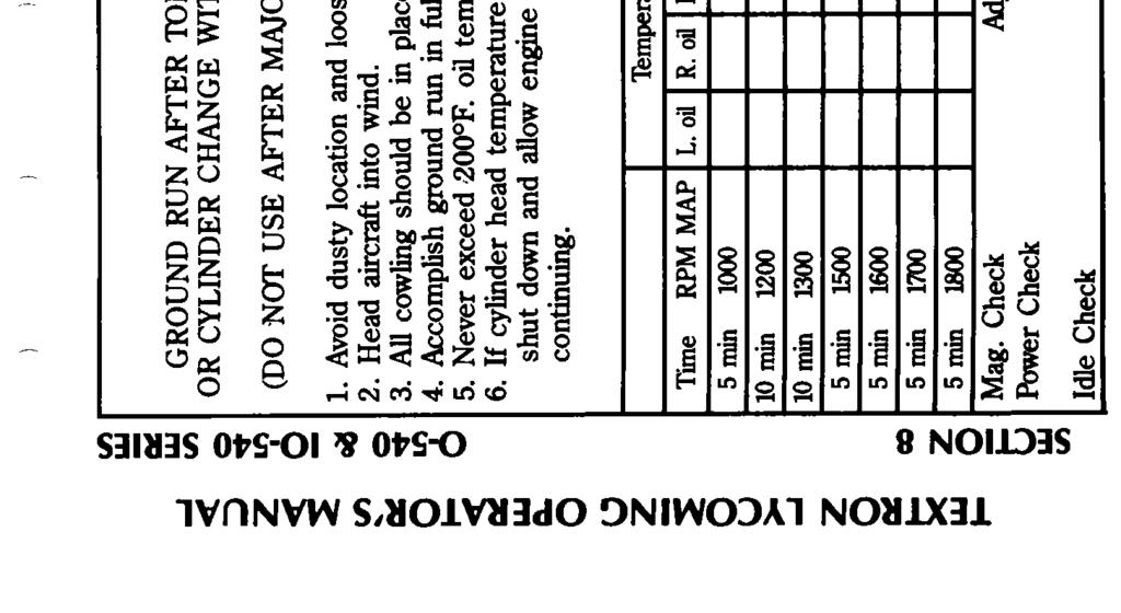
114
SECTION 4 PERIODIC INSPECTIONS NOTE
 LYCOMING OPERATOR S MANUAL SECTION 4 O-360 AND ASSOCIATED MODELS PERIODIC INSPECTIONS SECTION 4 PERIODIC INSPECTIONS NOTE Perhaps no other factor is quite so important to safety and durability of the aircraft
IO 390 A Series Operation and Installation Manual
 IO 390 A Series Operation and Installation Manual August 2008 (Cover Revised June 2009) FAA Approved Part No. 60297 34 2008 652 Oliver Street Williamsport, PA 17701 IO 390 A Series Operation and Installation
IO-720 Series. Operator s Manual Lycoming. Approved by FAA. 4 th Edition Part No
 Operator s Manual Lycoming IO-720 Series Approved by FAA 4 th Edition Part No. 60297-19 652 Oliver Street Williamsport, PA. 17701 U.S.A. 570/323-6181 October 2006 IO-720 Series Operator s Manual Lycoming
TIO-540-AE2A Series. Operator s Manual Lycoming. Approved by FAA. 2nd Edition Part No
 Operator s Manual Lycoming Series Approved by FAA 2nd Edition Part No. 60297-27 652 Oliver Street Williamsport, PA. 17701 U.S.A. 570/323-6181 November 2006 Series Operator s Manual Lycoming Part Number:
IO-360, AIO-360, HIO-360 & TIO-360 Series
 Operator s Manual Lycoming O-360, HO-360, IO-360, AIO-360, HIO-360 & TIO-360 Series Approved by FAA 8 th Edition Part No. 60297-12 652 Oliver Street Williamsport, PA. 17701 U.S.A. 570/323-6181 October
Operator s Manual Lycoming
 Operator s Manual Lycoming O-320 éê Series Approved by FAA 2nd Edition Part No. 60297-22 652 Oliver Street Williamsport, PA. 17701 U.S.A. 570/323-6181 April 2007 O-320 éê Series Operator s Manual Lycoming
SERVICE INSTRUCTION. 652 Oliver Street Williamsport, PA U.S.A. Tel Fax
 652 Oliver Street Williamsport, PA. 17701 U.S.A. Tel. 570 323 6181 Fax. 570 327 7101 www.lycoming.com SERVICE INSTRUCTION DATE: March 8, 2012 Service Instruction No. 1098H (Supersedes Service Instruction
Operators Manual Lycoming
 Operators Manual Lycoming TIO-541 Series Approved by FAA 3rd Edition Part No. 60297-13 652 Oliver Street Williamsport, PA. 17701 U.S.A. 570/323-6181 December 2007 TIO-541 Series Operators Manual Lycoming
SERVICE INSTRUCTION. All Certified Lycoming direct drive engines. TIME OF COMPLIANCE: At owner s discretion.
 652 Oliver Street Williamsport, PA. 17701 U.S.A. Telephone +1 (800) 258-3279 U.S. and Canada (Toll Free) Telephone +1 (570) 323-6181 (Direct) Facsimile +1 (570) 327-7101 Email Technicalsupport@lycoming.com
Accident Prevention Program
 Accident Prevention Program Part I ENGINE OPERATION FOR PILOTS by Teledyne Continental Motors SAFE ENGINE OPERATION INCLUDES: Proper Pre-Flight Use the correct amount and grade of aviation gasoline. Never
NOTE. In order to accommodate clearer type, larger charts and graphs, and more
 NOTE In order to accommodate clearer type, larger charts and graphs, and more detailed illustrations, this edition of the O-360, HO-360, IO-360, AIO-360, HIO-360 and TIO-360 Operator s Manual, Lycoming
Operation Reference Manual. Lycoming IO-390 SERIES. Part No Oliver Street Williamsport, PA U.S.A.
 Operation Reference Manual Lycoming Part No. 60297-29 652 Oliver Street Williamsport, PA. 17701 U.S.A. 570/323-6181 IO-390 Operation Reference Manual Lycoming Part Number: 60297-29 2007 by Lycoming. All
IO-360, AIO-360, HIO-360 & TIO-360 Series
 Operator s Manual Lycoming O-360, HO-360, IO-360, AIO-360, HIO-360 & TIO-360 Series Approved by FAA 8 th Edition Part No. 60297-12 652 Oliver Street Williamsport, PA. 17701 U.S.A. 570/323-6181 October
DATE: February 13, 2019 Service Instruction No. 1037V (Supersedes Service Instruction No. 1037U) Engineering Aspects are FAA Approved
 Engineering Aspects are FAA Approved") 652 Oliver Street Williamsport, PA. 17701 U.S.A. Telephone +1 (800) 258-3279 U.S. and Canada (Toll Free) Telephone +1 (570) 323-6181 (Direct) Facsimile +1 (570) 327-7101 Email Technicalsupport@lycoming.com
652 Oliver Street Williamsport, PA. 17701 U.S.A. Telephone +1 (800) 258-3279 U.S. and Canada (Toll Free) Telephone +1 (570) 323-6181 (Direct) Facsimile +1 (570) 327-7101 Email Technicalsupport@lycoming.com
DEPARTMENT OF TRANSPORTATION FEDERAL AVIATION ADMINISTRATION TYPE CERTIFICATE DATA SHEET NO. 1E12
 DEPARTMENT OF TRANSPORTATION FEDERAL AVIATION ADMINISTRATION TYPE CERTIFICATE DATA SHEET NO. 1E12 1E12 Revision 9 Lycoming Engines IO-320 -A1A-A2A-B1A, -B1B, B1C, -B1E, -B1D, -B2A, -C1A, -C1B, -D1A, -D1C,
European Aviation Safety Agency
 European Aviation Safety Agency EASA TYPE-CERTIFICATE DATA SHEET Number: IM.E.032 Issue: 01 Date: 27 September 2012 Type: Lycoming Engines Models IO-360-A1A IO-360-C1B AEIO-360-A1E6 HIO-360-F1AD IO-360-A1B
MANUAL OPERATOR'S REVISION Island Enterprises. 80 Operators Manual. are intended either to replace, add to, or delete
 OPERATOR'S REVISION MANUAL REVISION No. PUBLICATION PUBLICATION No. PUBLICATION DATE 60297-14-2 60297-14-2 GO, IGO, GSO, IGSO- 60297-14 July, 1973 80 Operators Manual The page(s) furnishedherewith pages
DEPARTMENT OF TRANSPORTATION FEDERAL AVIATION ADMINISTRATION TYPE CERTIFICATE DATA SHEET NO. E-223
 DEPARTMENT OF TRANSPORTATION FEDERAL AVIATION ADMINISTRATION E-223 Revision 18 Textron Lycoming O-233-A1,O-235 O-235-A,-B,-AP,-BP-C,-C1,-C1A,-C1B,-C1C,-C2A,-C2B,-C2C, -E1,-E1B,-E2A,-E2B,-F1,-F1B,-F2A,-F2B,-G1,-G1B,-G2A,-G2B,
OPERATOR'S MANUAL REVISION
 OPERATOR'S MANUAL REVISION REVISION NO. PUBLICATION PUBLICATION PUBLICATION NO. DATE TIO-540-AE2A 60297-27-2 Operator's Manual 60297-27 September 1988 The page(s) in this revision replace, add to, or delete
DATE: May 8, 2012 Service Instruction No. 1279C (Supersedes Service Instruction No. 1279B) Engineering Aspects are FAA Approved
 Engineering Aspects are FAA Approved") 652 Oliver Street Williamsport, PA. 17701 U.S.A. Tel. 570 323 6181 Fax. 570 327 7101 www.lycoming.com SERVICE INSTRUCTION DATE: May 8, 2012 Service Instruction No. 1279C (Supersedes Service Instruction
652 Oliver Street Williamsport, PA. 17701 U.S.A. Tel. 570 323 6181 Fax. 570 327 7101 www.lycoming.com SERVICE INSTRUCTION DATE: May 8, 2012 Service Instruction No. 1279C (Supersedes Service Instruction
TYPE CERTIFICATE DATA SHEET NO. E14EA. Avco Corporation Williamsport, Pennsylvania 17701
 DEPARTMENT OF TRANSPORTATION FEDERAL AVIATION ADMINISTRATION E14EA Revision 16 TEXTRON LYCOMING TIO-540-A1A, -A1B, -A2A, -A2B, -A1C, -A2C, -C1A, -E1A, -F2BD, -G1A, -H1A, -J2B, -J2BD, -K1AD, -N2BD, -R2AD,
DEPARTMENT OF TRANSPORTATION FEDERAL AVIATION ADMINISTRATION
 DEPARTMENT OF TRANSPORTATION FEDERAL AVIATION ADMINISTRATION 1E10 Revision No. 22 TEXTRON Lycoming IO-360-A1A, -A1B, -A1B6, -A1B6D, -A1C, -A1D, -A1D6, -A1D6D, -A2A, -A2B, -A2C, -A3B6,-A3B6D, -A3D6D, -B1A,
MANDATORY SERVICE BULLETIN
 652 Oliver Street Williamsport, PA 17701 U.S.A. Telephone +1 (800) 258-3279 (U.S. and Canada) Telephone +1 (570) 323-6181 (International) Facsimile +1 (570) 327-7101 www.lycoming.com MANDATORY SERVICE
Lycoming AIRCRAFT ENGINES. IO-540-AC1A5 Wide Series Flange Crankcase Model Engine PARTS CATALOG PC
 AIRCRAFT ENGINES IO-540-ACA5 Wide Series Flange Crankcase Model Engine PARTS CATALOG PC-5- November 008 Lycoming 5 Oliver Street Williamsport, PA 770 U.S.A. 570/33-8 IO-540-ACA5 PARTS CATALOG This illustrated
Frequently Asked Questions Certification 1. Are the ACS-320, ACS-360 and ACS-361 (ACS) Engines new zero time engines?
 Engines new zero time engines?") Frequently Asked Questions Certification 1. Are the ACS-320, ACS-360 and ACS-361 (ACS) Engines new zero time engines? Yes. The ACS Engines are brand new, zero time engines designed to meet the increasing
Frequently Asked Questions Certification 1. Are the ACS-320, ACS-360 and ACS-361 (ACS) Engines new zero time engines? Yes. The ACS Engines are brand new, zero time engines designed to meet the increasing
LYCOMING CYLINDER PRICING
 SHIPPING: 2415 EMBARCADERO WAY, PALO ALTO, CA 94303 MAILING: P.O. BOX 50608, PALO ALTO, CA. 94303-0608 Phone: 650-354-1399 Fax: 650-354-1395 LYCOMING CYLINDER PRICING CYLINDER PRICING ENGINE MODEL: O-235
Copyright 2015 Airmotive Engineering Corp.
 Copyright 2015 Airmotive Engineering Corp. All rights reserved. Permission to reproduce or transmit in any form or by any means, electronic or mechanical, including photocopying and recording, or by any
O-540-A4B5 PARTS CATALOG WIDE CYLINDER FLANGE CRANKCASE MODEL ENGINES
 INTRODUCTION This illustrated parts catalog contains a complete parts listing for the Lycoming O-540-A4B5 wide cylinder flange crankcase model aircraft engines. Major assembly and sub-assembly parts of
Crankshaft Gear Retaining Bolt Replacement NOTE
 652 Oliver Street Williamsport, PA 17701 U.S.A. Tel. 570-323-6181 Fax. 570-327-7101 www.lycoming.textron.com MANDATORY SERVICE BULLETIN DATE: September 30, 2002 Engineering Aspects of this Service Bulletin
P-920, Revision 32 Page 2 of 13
 DEPARTMENT OF TRANSPORTATION P-920 FEDERAL AVIATION ADMINISTRATION Revision 32 Hartzell HC-C2Y, BHC-C2Y, CHC-C2Y, DHC-C2Y TYPE CERTIFICATE DATA SHEET NO. P-920 March 9, 2010 Propellers of models described
CIRRUS AIRPLANE MAINTENANCE MANUAL
 POWER PLANT 1. GENERAL This chapter describes maintenance practices for the airplane systems which provide the means to induce and convert fuel-air mixture into power such as the engine, baffling, cowling,
MOONEY INTERNATIONAL CORPORATION The Symbol of Performancet MOONEY SPECIAL LETTER Date:
 MOONEY INTERNATIONAL CORPORATION The Symbol of Performancet MOONEY SPECIAL LETTER 15-24 Date: 11-19-2015 SUBJECT: MODELS/ S/N AFFECTED: To ADVISE MOONEY OWNERS/OPERATORS of the LYCOMING Service Instruction
DEPARTMENT OF TRANSPORTATION FEDERAL AVIATION ADMINISTRATION TYPE CERTIFICATE DATA SHEET NO. E-275. Avco Corporation Williamsport, Pennsylvania 17701
 DEPARTMENT OF TRANSPORTATION FEDERAL AVIATION ADMINISTRATION TYPE CERTIFICATE DATA SHEET NO. E-275 E-275 Revision 10 AVCO Lycoming GO-480, GO-480-A1A, -B, -B1, -B1A6, -B1B, -B1C, -B1D, -C1B6, -C1D6, -C2C6,
IO-540-AE1A5 Series Illustrated Parts Catalog
 IO-540-AE1A5 Series Illustrated Parts Catalog PC-615-AE1A5 (Replaces PC-615-13) 2013 652 Oliver Street Williamsport, PA 17701 IO-540-AE1A5 Series Illustrated Parts Catalog PC-615-AE1A5 (Replaces PC-615-13)
SERVICE INSTRUCTION. ISSUED REVISED PAGE NO. REVISION MO DAY YEAR MO DAY YEAR 1 of 8 BB
 652 Oliver Street Williamsport, PA. 17701 U.S.A. Telephone +1 (800) 258-3279 U.S. and Canada (Toll Free) Telephone +1 (570) 323-6181 (Direct) Facsimile +1 (570) 327-7101 Email Technicalsupport@lycoming.com
OPERATING RECOMMENDATIONS
 Operating Recommendations for TIO-540-AE2A Engine in Piper Aircraft Malibu Mirage Lycoming Part Number: SSP-400 OPERATING RECOMMENDATIONS FOR TIO-540-AE2A ENGINE IN PIPER AIRCRAFT MALIBU MIRAGE 2009 by
Lycoming Aircraft Engines Parts Catalog
 Aircraft Engines Parts Catalog IO-0-BG Wide Cylinder Flange Crankcase Model Engine Part No. PC-0- Oliver Street Williamsport, PA 770 Aircraft Engines Parts Catalog IO-0-BG Wide Cylinder Flange Crankcase
TYPE-CERTIFICATE DATA SHEET
 TYPE-CERTIFICATE DATA SHEET For Models: IO-390-A1A6 IO-390-A3A6 IO-390-A1B6 IO-390-A3B6 AEIO-390-A1A6 AEIO-390-A3A6 AEIO-390-A1B6 AEIO-390-A3B6 IO-390-C1A6 IO-390-C3A6 IO-390-C1B6 IO-390-C3B6 No. IM.E.097
MANDATORY SERVICE BULLETIN
 652 Oliver Street Williamsport, PA 17701 U.S.A. Telephone +1 (800) 258-3279 (U.S. and Canada) Telephone +1 (570) 323-6181 (International) Facsimile +1 (570) 327-7101 Email Technicalsupport@lycoming.com
DEPARTMENT OF TRANSPORTATION FEDERAL AVIATION ADMINISTRATION TYPE CERTIFICATE DATA SHEET NO. E-228
 DEPARTMENT OF TRANSPORTATION FEDERAL AVIATION ADMINISTRATION O-435, -A, -A2 O-435-B (O-435-5) O-435-C (O-435-1) O-435-C1 (O-435-11) O-435-C2 (O-435-13) O-435-K O-435-K1 (O-435-4) E-228 Revision 16 AVCO
VACUUM PRESSURE PUMPS INSTALLATION CAUTIONS AND INFORMATION READ AND FOLLOW CAREFULLY!
 F.A.A.-P.M.A. MODEL 1U128A AND 1U128B REVISION 17 February 21, 2002 VACUUM PRESSURE PUMPS INSTALLATION CAUTIONS AND INFORMATION READ AND FOLLOW CAREFULLY! The following information applies to all installations
********NOTICE********
 IO-540-K1A5 Series Illustrated Parts Catalog February 2015 ********NOTICE******** This parts catalog, PC-615-K1A5 Series (models IO-540-K1A5, IO-540-K1A5D) supersedes the previous IO-540-K1A5, IO-540-K1A5D
Service Instruction ENGINE COMPONENTS, INC.
 Title: Service Instruction S.I. No.: 89-5-1 Page: 1 of 5 Issued: 05/05/89 Revision: 1 (09/01/01) Technical Portions of FAA DER Approved. FAILURE OF ENGINE TO START 27 points 1. Lack of fuel 2. Ignition
LYCOMING OPERATOR'S MANUAL ATTENTION OWNERS, OPERATORS, AND MAINTENANCE PERSONNEL
 OPERATOR'S MANUAL -l-540. 10-540 & H10-540 SERIES AIRCRAFT ENGINES 1st Edition.July 1976 Approved by F.A.A. Part No. 60297-10 Price $5.00..::::10AVCD LYCOMING WILLIAMSPORT DIVISION AVCO CORPORATION WILLIAMSPORT.
O-540-F1B5 SERIES PARTS CATALOG WIDE CYLINDER FLANGE CRANKCASE MODEL ENGINES
 INTRODUCTION This illustrated parts catalog contains a complete parts listing for the Lycoming O-540-F1B5 series wide cylinder flange crankcase model aircraft engines. Major assembly and sub-assembly parts
YIO-390-B Series Operation and Installation Manual
 YIO-390-B Series Operation and Installation Manual November 2009 Part No. 60297-37 2009 652 Oliver Street Williamsport, PA 17701 YIO-390-B Series Operation and Installation Manual November 2009 Part No.
European Aviation Safety Agency
 European Aviation Safety Agency EASA TYPE-CERTIFICATE DATA SHEET Number : IM.E.027 Issue : 02 Date : 06 May 2008 Type : Lycoming IO-580 series engines Variants Lycoming IO-580-B1A Lycoming AEIO-580-B1A
TEXTRON Lycoming AIRCRAFT ENGINES
 TEXTRON Lycoming AIRCRAFT ENGINES O-60-AP Wide Cylinder Flange Crankcase Model Engines PARTS CATALOG PC-06-6 MARCH 99 0-60-AP PARTS CATALOG This illustrated parts catalog contains a complete parts listing
IO-540-K1H5 Series Illustrated Parts Catalog
 IO-50-KH5 Series Illustrated Parts Catalog November 983 Engine model IO-50-KK5, previously covered in this parts catalog, has been superseded by PC-5-KK5. PC-5-03 5 Oliver Street Williamsport, PA 770 IO-50-KH5
LYCOMING A Textron Company
 LYCOMING AEIO-360-HB PARTS CATALOG This illustrated parts catalog contains a complete parts listing for the Lycoming AEIO-360-HB wide cylinder flange crankcase model aircraft engines. Major assembly and
Lycoming Aircraft Engines Parts Catalog
 Lycoming Aircraft Engines Parts Catalog 76 Series O-360, LO-360 Series Part No. PC-3 65 Oliver Street Williamsport, PA 770 Lycoming Aircraft Engines Parts Catalog 76 Series O-360, LO-360 Series Part No.
2003 Lycoming. All rights reserved. Lycoming and "Powered by Lycoming" are trademarks or registered trademarks of Lycoming.
 O-50-AD5 Engine Parts Catalog Lycoming Part Number: PC-55-3 003 Lycoming. All rights reserved. Lycoming and "Powered by Lycoming" are trademarks or registered trademarks of Lycoming. All brand and product
O-320-H 76 Series Illustrated Parts Catalog
 O-320-H 76 Series Illustrated Parts Catalog PC-122-H 76 Series 2013 652 Oliver Street Williamsport, PA 17701 O-320-H 76 Series Illustrated Parts Catalog PC-122-H 76 Series 2013 652 Oliver Street Williamsport,
IO 360 M1B Series Illustrated Parts Catalog
 IO 360 M1B Series Illustrated Parts Catalog January 2011 PC 306 16 2011 652 Oliver Street Williamsport, PA 17701 Lycoming Part Number: PC 306 16 2011 by Avco Corporation. All Rights Reserved. Lycoming
O-360 & IO-360 Series Model Specification Summary
 O-360 & IO-360 Series Model Specification Summary 621 South Royal Lane, Suite 100 / Coppell, TX 75019 / 800-277-5168 www.superior-air-parts.com Technical Data Summary Design Highlights O-360 IO-360 Rating
O 540 A4E5 Series Illustrated Parts Catalog
 O 540 A4E5 Series Illustrated Parts Catalog April 2012 PC 515 A4E5 2012 652 Oliver Street Williamsport, PA 17701 Lycoming Part Number: PC 515 A4E5 2012 by Avco Corporation. All Rights Reserved. Lycoming
O-320-A2C, -A2D Series Illustrated Parts Catalog
 O-320-A2C, -A2D Series Illustrated Parts Catalog September 2011 PC-203-2 2011 652 Oliver Street Williamsport, PA 17701 O-320-A2C, -A2D Illustrated Parts Catalog Lycoming Part Number: PC-203-2 2011 by Avco
Lycoming Aircraft Engines Parts Catalog
 Lycoming Aircraft Engines Parts Catalog TIO-360-CA6D Wide Cylinder Flange Models Part No. PC-06-3 65 Oliver Street Williamsport, PA 770 Lycoming Aircraft Engines Parts Catalog TIO-360-CA6D Wide Cylinder
7. Are you upgrading a complete engine from a TCM/ Bendix to a Slick system? If yes, purchase a complete Slick Ignition Upgrade Kit.
 1.1 PRODUCT APPLICATION INFORMATION WORKSEET The following information will aid you in selecting the correct magneto, upgrade kit, or ignition harness: 1. Engine Manufacturer 2. Engine Model Number 3.
O-320-E2G Series Illustrated Parts Catalog
 O-320-E2G Series Illustrated Parts Catalog December 2011 PC-203-7 2011 652 Oliver Street Williamsport, PA 17701 O-320-E2G Illustrated Parts Catalog Lycoming Part Number: PC-203-7 2011 by Avco Corporation.
O-360-A4N Series Illustrated Parts Catalog
 O-360-A4N Series Illustrated Parts Catalog May 2011 PC-306-3 2011 652 Oliver Street Williamsport, PA 17701 Lycoming Part Number: PC-306-3 2011 by Avco Corporation. All Rights Reserved. Lycoming and Powered
DATE: February 24, 2014 Service Instruction No. 1009AW (Supersedes Service Instruction No. 1009AV) Engineering Aspects are FAA Approved
 Engineering Aspects are FAA Approved") 652 Oliver Street Williamsport, PA. 17701 U.S.A. Telephone +1 (800) 258 3279 U.S. and Canada (Toll Free) Telephone +1 (570) 323 6181 (Direct) Facsimile +1 (570) 327 7101 www.lycoming.com SERVICE INSTRUCTION
652 Oliver Street Williamsport, PA. 17701 U.S.A. Telephone +1 (800) 258 3279 U.S. and Canada (Toll Free) Telephone +1 (570) 323 6181 (Direct) Facsimile +1 (570) 327 7101 www.lycoming.com SERVICE INSTRUCTION
PUBLICATION REVISION
 Lycomlng 65 Oliver Street Williamsport, PA 770 U.S.A. 77/-6 TECHNICAL PUBLICATION REVISION REVISIOI No. PUBLICATION PUBLICATION No. PUBLICATION DATE IO-60-LA PC-06-A Engines PC-06- MAY, 996 This page(s)
O-360-C1G Series Illustrated Parts Catalog
 O-360-C1G Series Illustrated Parts Catalog April 2011 PC-306-4 2011 652 Oliver Street Williamsport, PA 17701 Lycoming Part Number: PC-306-4 2011 by Avco Corporation. All Rights Reserved. Lycoming and Powered
SERVICE INSTRUCTION. Lycoming engines that meet defined criteria herein. REASON FOR REVISION: Added IO-360-N and IO-390-C engine models
 652 Oliver Street Williamsport, PA. 17701 U.S.A. Telephone +1 (800) 258-3279 U.S. and Canada (Toll Free) Telephone +1 (570) 323-6181 (Direct) Facsimile +1 (570) 327-7101 www.lycoming.com SERVICE INSTRUCTION
TECHNICAL PUBLICATION SUPPLEMENT
 TEXTRON Lycoming TECHNICAL PUBLICATION SUPPLEMENT SUPPLEMENT No. ENGINE MODEL PUBLICATION No. PUBLICATION DATE PC-0--B O-90-D Series PC-0- January 9 This supplement is arranged in the same basic format
O-320-A2B, -A3B Series Illustrated Parts Catalog
 O-320-A2B, -A3B Series Illustrated Parts Catalog August 2011 PC-203-1 2011 652 Oliver Street Williamsport, PA 17701 O-320-A2B, -A3B Illustrated Parts Catalog Lycoming Part Number: PC-203-1 2011 by Avco
Accident Prevention Program
 Accident Prevention Program Maintenance Aspects of Owning Your Own Airplane Introduction As an owner-pilot, FAR Part 43 allows you to perform certain types of inspections and maintenance on your airplane.
REMOVAL AND INSTALLATION LABOR ALLOWANCE GUIDEBOOK FOR RECIPROCATING AIRCRAFT ENGINES
 REMOVAL AND INSTALLATION LABOR ALLOWANCE GUIDEBOOK FOR RECIPROCATING AIRCRAFT ENGINES SSP-875 Revision May 2000 2000 by Textron Lycoming All Rights Reserved -INTRODUCTION- The labor hours shown in this
TIO-540-AJ1A Illustrated Parts Catalog
 TIO-540-AJ1A Illustrated Parts Catalog May 2016 PC-TIO-540-AJ1A (Supersedes PC-315-12) 2016 652 Oliver Street Williamsport, PA 17701 Lycoming Part Number: PC-TIO-540-AJ1A (Supersedes PC-315-12) For additional
9.7 Replacement of the compressed air distributor
 9.6.6 9.6.7 screw in the bolt and to increase unscrew the bolt. For a complete rotation of the bolt, the variation is of 1mm. After measuring the pointer position and the compensatory adjustment screw
Carburetor Instructions
 Carburetor Instructions for HUDSON SUPER SIX ESSEX SIX CYLINDER Hudson Motor Car Co. DETROIT, U.S.A. Carburetor The carburetor is a device for metering correct amounts of fuel and air for the various
PARTS CATALDG AIRCRAFT ENGINES
 PARTS CATALDG PC B115-1 AVCC L VCCMING IC-154D-C4D15D MCDEL Wide Cylinder Flange Model AIRCRAFT ENGINES..JULY 19S2 L1L7AVCa LYCOMING WILLIAMSPORT DIVISION 852 Oliver Street. Williamsport. Pennsylvania
O-320-E2D, -E3D Series Illustrated Parts Catalog
 O-320-E2D, -E3D Series Illustrated Parts Catalog October 2011 PC-203-6 2011 652 Oliver Street Williamsport, PA 17701 O-320-E2D, -E3D Series Illustrated Parts Catalog October 2011 PC-203-6 2011 652 Oliver
LIO-360-B1G6 Illustrated Parts Catalog
 LIO-360-B1G6 Illustrated Parts Catalog July 2017 PC-LIO-360-B1G6 2017 Lycoming Part Number: PC-LIO-360-B1G6 For additional information: Mailing address: Lycoming Engines 652 Oliver Street Williamsport,
O-320-D3G Series Illustrated Parts Catalog
 O-320-D3G Series Illustrated Parts Catalog AUGUST 2012 PC-203-D3G 2012 652 Oliver Street Williamsport, PA 17701 O-320-D3G Series Illustrated Parts Catalog AUGUST 2012 PC-203-D3G 2012 652 Oliver Street
O-320-E1A, -E2A Series Illustrated Parts Catalog
 O-320-E1A, -E2A Series Illustrated Parts Catalog November 2011 PC-203-3 2011 652 Oliver Street Williamsport, PA 17701 O-320-E1A, -E2A Illustrated Parts Catalog Lycoming Part Number: PC-203-3 2011 by Avco
PIPER AIRCRAFT PA NOTE- Perform all inspections or operations at each oj the inspection. 1. Inspectspinnerandbackplate
 PPER ARCRAFT PA-38-111 (.MANTENANCE MANUAL SCHEDULED MANTENANCE. PERODC NSPECTONS. -NOTE- Perform all inspections or operations at each oj the inspection intervals as indicated by a circle (). nspection
Jump to Table of Contents
 Jump to Table of Contents PIPER AIRCRAFT CORPORATION PA-28R-201, CHEROKEE ARROW III SECTION 3 EMERGENCY PROCEDURES 3.3 EMERGENCY PROCEDURES CHECK LIST ENGINE FIRE DURING
PIPER AIRCRAFT CORPORATION
 PA-28-181 INSPECTION REPORT ARCHER II ARCHER III PIPER AIRCRAFT CORPORATION (PART NUMBER 230 1039) PIPER AIRCRAFT CORPORATION INSPECTION REPORT This form meets requirements of FAR Part 43 Inspections must
TYPE CERTIFICATE DATA SHEET NO. E1CE
 DEPARTMENT OF TRANSPORTATION FEDERAL AVIATION ADMINISTRATION Revision 17 CONTINENTAL IO-360-A, -B, -C, -D, -E, -G, -H, -J, -K, -AB, AF, -DB, -GB,-HB, -JB, -KB, -ES TYPE CERTIFICATE DATA SHEET NO. January
CARENADO COPYRIGHTS. Normal & Emergency Checklist
 NORMAL PROCEDURES CHECKLIST PREFLIGHT CHECK Control wheel -- RELEASE BELTS Avionics -- OFF Master Switch -- ON Fuel quantity gauges -- CHECK Master switch -- OFF Ignition -- OFF Exterior -- CHECK FOR DAMAGE
(L)IO-360-M1A Illustrated Parts Catalog
IO-360-M1A Illustrated Parts Catalog") (L)IO--M1A Illustrated Parts Catalog February 2016 PC-(L)IO--M1A (Supersedes PC-306-14) 2016 652 Oliver Street Williamsport, PA 17701 Lycoming Part Number: PC-(L)IO--M1A (Supersedes PC-306-14) 2016 by
(L)IO--M1A Illustrated Parts Catalog February 2016 PC-(L)IO--M1A (Supersedes PC-306-14) 2016 652 Oliver Street Williamsport, PA 17701 Lycoming Part Number: PC-(L)IO--M1A (Supersedes PC-306-14) 2016 by
Lycoming Aircraft Engines Parts Catalog
 Lycoming Aircraft Engines Parts Catalog GO-480-B, -D and F6 Series Aircraft Engines Part No. PC-111 652 Oliver Street Williamsport, PA 17701 Lycoming Aircraft Engines Parts Catalog GO-480-B, -D and F6
Avco Lycoming Service Letter No. L218 and Service Instruction No. 1059C, No. 1110C and No. 1257E
 VSP-75 August 14, 1987 S/M VENDOR PUBLICATION TO: All Piper Distributors, Factory Direct Dealers and Piper Field Service Facilities Avco Lycoming Service Letter No. L18 and Service Instruction No. 1059C,
Elmendorf Aero Club Aircraft Test
 DO NOT WRITE ON THIS TEST FEB 2013 Elmendorf Aero Club Aircraft Test Cessna 172RG For the following questions, you will need to refer to the Pilots Information Manual for the C-172RG and the Auxiliary
DATE: May 19, 2000 Service Instruction No. 1443E (Supersedes Service Instruction No. 1443D) Engineering Aspects are FAA Approved
 Engineering Aspects are FAA Approved") DATE: May 19, 2000 (Supersedes Service Instruction No. 1443D) Engineering Aspects are FAA Approved SUBJECT: MODELS AFFECTED: TIME OF COMPLIANCE: Approved Slick Magnetos on Textron Lycoming Engines See
DATE: May 19, 2000 (Supersedes Service Instruction No. 1443D) Engineering Aspects are FAA Approved SUBJECT: MODELS AFFECTED: TIME OF COMPLIANCE: Approved Slick Magnetos on Textron Lycoming Engines See
YO-233-B2A Illustrated Parts Catalog
 YO-233-B2A Illustrated Parts Catalog March 2016 PC-YO-233-B2A Supersedes PC-901-1 2016 652 Oliver Street Williamsport, PA 17701 Lycoming Part Number: PC-YO-233-B2A Supersedes PC-901-1 2016 by Avco Corporation.
(j ~ichita~hraft Certification Office Federal Aviation Administration
 , 6- AIR PLAMS SERVICES, CORP WELLrfiCTON ALRPORT ItTLLINGTON, U.67 152 SUPPLEhENTXL AIRPLANE FLIGHT MAMJAL C180 Serial Numhers: 18051446 through I8052103 STC SA0078AT F.A.A. APPROVED Reg. No. Ser. No.
INSTALLATION AND DETAIL SPECIFICATIONS FOR THE SILVER HAWK TM EX-5VA1 TM SERVO KIT
 INSTALLATION AND DETAIL SPECIFICATIONS FOR THE SILVER HAWK TM EX-5VA1 TM SERVO KIT 25-020_C.DOC 2-23-2015 Precision Airmotive LLC fuel systems are produced using the highest quality materials and components.
O-360-A4M Series Illustrated Parts Catalog
 O-360-A4M Series Illustrated Parts Catalog PC-306-A4M 2012 652 Oliver Street Williamsport, PA 17701 O-360-A4M Series Illustrated Parts Catalog PC-306-A4M 2012 652 Oliver Street Williamsport, PA 17701 O-360-A4M
Lycoming Aircraft Engines Parts Catalog
 Aircraft Engines Parts Catalog TIO-540 Series Standard Cylinder Flange Crankcase Models Part No. PC-35-6 652 Oliver Street Williamsport, PA 770 Reciprocating Engine Division/ Subsidiary of Textron Inc.
COLT 2310, 2510, AND 2712 COM PACT TRACTORS CHAPTER 9 TROUBLESHOOTING AND ANALYSIS
 COLT 2310, 2510, AND 2712 COM PACT TRACTORS CHAPTER 9 TROUBLESHOOTING AND ANALYSIS 9-A-1 UPON RECEIVING ANENGINE FORRE- PAIR. Learn the history of the unit from the customer. While the customer is present
Lycoming Aircraft Engines Parts Catalog
 Lycoming Aircraft Engines Parts Catalog AEIO-50-D Series -DA5, -DB5 Wide Cylinder Flange Crankcase Model Engines Part No. PC-5-5 Oliver Street Williamsport, PA 770 Textron Lycoming 5 Oliver Street Williamsport,
Lycoming Aircraft Engines Parts Catalog
 Aircraft Engines Parts Catalog TIO/LTIO-540-V2AD Wide Cylinder Flange Model Part No. PC-35-2 652 Oliver Street Williamsport, PA 770 Aircraft Engines Parts Catalog TIO/LTIO-540-V2AD Wide Cylinder Flange
1) Scheduled maintenance checks
 Scheduled maintenance checks") 1) Scheduled maintenance checks Definition This section lists the periodic inspections which must be carried out after a specified periods of operation. Intervals Periodic inspections are those which must
1) Scheduled maintenance checks Definition This section lists the periodic inspections which must be carried out after a specified periods of operation. Intervals Periodic inspections are those which must
MANDATORY SERVICE BULLETIN
 652 Oliver Street Williamsport, PA 17701 U.S.A. Tel. 1 800 258 3279 (U.S. and Canada) Tel. 1 570 323 6181 (International) Fax. 1 570 327 7101 www.lycoming.com MANDATORY SERVICE BULLETIN DATE: October 4,
SERVICE LETTER. Service Letter No. L114AN (Supersedes Service Letter No. L114AM) February 3, Owners and Operators of Lycoming Aircraft Engines
 February 3, Owners and Operators of Lycoming Aircraft Engines") 652 Oliver Street Williamsport, PA. 17701 U.S.A. Tel. 570-323-6181 Fax. 570-327-7101 www.lycoming.textron.com SERVICE LETTER Service Letter No. L114AN (Supersedes Service Letter No. L114AM) February 3,
652 Oliver Street Williamsport, PA. 17701 U.S.A. Tel. 570-323-6181 Fax. 570-327-7101 www.lycoming.textron.com SERVICE LETTER Service Letter No. L114AN (Supersedes Service Letter No. L114AM) February 3,
I. DISPATCH PLANNING & AIRCRAFT EXTERIOR CHECK
 SCHODACK AVIATION Page 1 of 10 I. DISPATCH PLANNING & AIRCRAFT EXTERIOR CHECK 1. Flight Planning 1. Aircraft requirements & preparation: 1. Required aircraft documents: 1. Airworthiness Certificate 2.
TEXTRON Lycoming AIRCRAFT ENGINES
 TEXTRON Lycoming AIRCRAFT ENGINES O-60-CF & -CP Wide Cylinder Flange Crankcase Model Engines PARTS CATALOG PC-06- OCTOBER 995 65 Oliver Street Williamsport, PA 770 U.S.A. 77/-6 Lycoming O-60-CF &-CP PARTS