NATIONAL TRANSPORTATION SAFETY BOARD Office of Aviation Safety Washington, D.C POWERPLANT GROUP CHAIRMAN S FACTUAL REPORT
|
|
|
- Violet Quinn
- 5 years ago
- Views:
Transcription

1 NATIONAL TRANSPORTATION SAFETY BOARD Office of Aviation Safety Washington, D.C June 9, 2008 May 11, 2009 POWERPLANT GROUP CHAIRMAN S FACTUAL REPORT NTSB No: DCA-09-MA-021 A. ACCIDENT Location: Denver International Airport, Denver Colorado Date: December 21, 2008 Time: 18:18 local Mountain Standard Time Aircraft: Continental Airlines Boeing , flight number 1404, registration number N18611 B. POWERPLANTS GROUP Safety Board Group Chairman: Federal Aviation Administration Member: Continental Airlines Member: Airline Pilot s Association Member: CFM Member: Jean-Pierre Scarfo - Powerplant Lead Engineer Washington D.C. Kevin E Miller Powerplant Program Manager, ASAA CMO Seattle, Washington Roger Cooper Propulsion Engineer Houston, Texas Rod Herrig ALPA Continental Airlines Safety Houston, Texas Ken Wolski Flight Safety Office Cincinnati, Ohio 1 of 16
2 NTSB NO: DCA-09-MA-021 C. SUMMARY On December 20, 2008, at 18:18 Mountain Standard Time (MST), Continental Airlines flight 1404, a Boeing (registration N18611), equipped with CFM56-3B1 engines, departed the left side of runway 34R during takeoff from Denver International Airport (DEN). The scheduled, domestic passenger flight, operated under the provisions of Title 14 CFR Part 121, was enroute to George Bush Intercontinental Airport (IAH), Houston, Texas. There were 37 injuries between the passengers and crew, and no fatalities. The airplane was substantially damaged and experienced a post-crash fire. The weather observation in effect at the time of the accident was reported to be winds at 290 and 24 knots with gusts to 32 knots, visibility of 10 miles, a few clouds at 4,000 feet and scattered clouds at 10,000 feet. The temperature was reported as -4 C (Celsius). The No. 1 engine had become detached from the left-hand wing during the crash sequence while the No. 2 engine remained attached to right-hand wing. The airplane came to rest on its belly and on the No. 2 engine. Examination of both engines reveals no indications of any engine case uncontainments, or no pre-accident under cowl fire. All the fan blades on both engines were present and exhibited varying degrees of damage consistent with engine rotation during the crash sequence. The No. 1 engine ingested dirt and earth debris throughout the fan stage. The No. 2 engine did exhibit fire damage and thermal distress to the inboard cowls consistent with the fire that occurred on the right-hand side of the aircraft after the crash. The low pressure turbine (LPT) for the No. 1 engine was not accessible; however, the No. 2 engine was and all the visible stage 4 LPT blades were present, intact, and straight. According to the Flight Data Recorder, the engine speed spooled up to the desired takeoff (T/O) power and no engines anomalies were noted during the takeoff roll for either engine while the airplane remained on the runway. About two seconds after the airplane departed the runway, the No. 1 engine experienced an uncommanded deceleration (no corresponding recorded throttle movement) while the No. 2 engine remained at the T/O setting. Up until this point, neither throttle had been reduced from their takeoff power setting. About three seconds after the airplane departed the runway both throttles were brought back to idle, and about one second later the thrust reversers were deployed. 2 of 16
3 NTSB NO: DCA-09-MA-021 D. DETAILS OF THE INVESTIGATION 1.0 ENGINE INFORMATION 1.1 ENGINE HISTORY The accident airplane, registration number N18611, was equipped with two CFM56-3B1 turbofan engines. The engine serial numbers (SN) were and for the No. 1 and No. 2 engines respectively. The No. 1 engine was installed on the accident airplane on August 6, The engine had accumulated 20,124 cycles since new (CSN) and 38,292 hours time since new (TSN) when installed on August The last maintenance action was on August 5, 2008 where the engine was inspected after coming off another airplane for customer convenience prior to installation on N The last engine repair 1 was performed by GE Engine Services Strother facility in Winfield, Kansas in June The engine had accumulated 17,013 CSN and 32,345 hours TSN at the time of the last repair (APPENDIX 1). The No. 2 engine was installed on the accident airplane December 18, The engine had accumulated 12,158 CSN and 22,785 hours TSN when installed on December The last maintenance, which was also the last repair, was performed by GE Engine Services Strother facility on December 9, 2006 (SEE APPENDIX 1). At the time of the accident the engines, had accumulated the cycles and times listed in TABLE 1. Table: 1: Engine Times and Cycles at the Time of the Accident No. 1 Engine No. 2 Engine cycles since new (CSN) 20,552 14,926 cycles since last installation (CSLI) 428 2,768 cycles since last repair (CSLR) 3,539 2,768 time since new (TSN) hours 39,092 28,081 time since last installation (TSLI) hours 800 5,296 time since last repair (TSLR) hours 6,747 5, ENGINE INFORMATION The CFM56-3B1 is a high bypass, dual-rotor, axial flow turbofan engine. A single-stage HPT drives the 9-stage HPC. The integrated fan and low pressure compressor (booster) are driven by a 4-stage low pressure turbine (LPT). The annular designed combustion chamber increases the HPC discharge air velocity to drive the high and low pressure turbines. An accessory drive system provides drive requirements for engine mounted aircraft accessories. The CFM56-3 utilizes an electronic Power Management Control (PMC) system to provide an automatic and precise power while retaining the reliable hydromechanical main fuel control system. The system controls fan speed and permits automatic thrust control during takeoff, climb and cruise operations as well as during the emergency go-around and maximum continuous operational modes. CFM is a partnership between General Electric in the USA and Snecma (Société Nationale d'etude et de Construction de Moteurs d'aviation) Moteurs of France. CFM is not an acronym; however, the company (CFM) and product line (CFM56) receive their names by a combination of the two parent companies commercial engine designations: GE s CF6 and Snecma s M56. The division of labor is such that Snecma is 1 Continental refers to a repair as an engine overhaul or restoration. 3 of 16
4 NTSB NO: DCA-09-MA-021 responsible for the fan and LPT modules while GE is responsible for the remainder of the engine HPC, combustion, and HPT. All directional references to front and rear, right and left, top and bottom, and clockwise and counterclockwise are made aft looking forward (ALF) as is the convention. The direction of rotation of the engine is clockwise. All numbering in the circumferential direction starts with the No. 1 position at the 12:00 o clock position, or immediately clockwise from the 12:00 o clock position and progresses sequentially clockwise ALF. FIGURE 1: CFM56 ENGINE CROSS SECTION 4 of 16

 2.1.1 General Engine Location and Cowl & Thrust Reverser Condition The No.")
 from the airplane fuselage (PHOTO 2).")
.")
5 NTSB NO: DCA-09-MA ON-SITE AND IN-SITU ENGINE EXAMINATION The following engine, engine cowl, and thrust reverser descriptions are in the as-found condition; these parts had not been moved by recovery or airport rescue and firefighting (ARFF) personnel. Therefore, not all parts of the engine or engine associated hardware were visible for examination. The descriptions in this section only pertain to those areas that were accessible and visible. 2.1 NO. 1 ENGINE CFM56-3B1 SN (LEFT-HAND SIDE) General Engine Location and Cowl & Thrust Reverser Condition The No. 1 engine was found detached from the airplane and was resting on its right-hand side to the left of its installed position on the left wing (PHOTO 1). The engine was oriented in the general direction of travel and canted away (left) from the airplane fuselage (PHOTO 2). The pylon was detached from the wing but remained attached to the engine (PHOTO 3). Much of the thrust reverser structure had separated from the engine. Pieces of the blocker doors, cascades, and thruster reverser fixed structure remained attached to the engine (PHOTOS 2 & 3). The forward engine mounts were obscured by the pylon; therefore, their condition was not documented. However, the aft engine mount was exposed allowing visual confirmation that both aft mount attachment points, which are integral to turbine rear frame, were intact. The pylon upper link (dog-bone shaped link) was intact and remained attached to the pylon by its installation pin. The upper link aft eyelet, where the fuse pin would have been located, was intact but the spherical bearing was damaged (PHOTO 4). PHOTO 1: NO. 1 ENGINE DETACHED PHOTO 2: FORWARD & LEFT OF LEFT WING PHOTO 3: TOP OF ENGINE PYLON ATTACHED PHOTO 4: NO. 1 ENGINE 6:00 O CLOCK POSITION 5 of 16


, part of the accessory gearbox, constant speed drive generator, engine lubrication and scavenge pump, fan cowl, and engine air turbine starter (PHOTO 6).")
6 NTSB NO: DCA-09-MA-021 Ground scars were located north of taxiway WC between taxiway WC and Kewaunee Street that were consistent in size and shape with the engine cowlings and on the south side of the Kewaunee Street berm, were two large semi-circular impact marks consistent with the size and shape of the lower part of the inlet. Also noted were ground scars consistent with the airplane s nose and main landing gears (Photo 5). Scattered along the airplane s path of travel after it had departed the runway and went over the Kewaunee Street berm were various parts and components from the engine and thrust reverser. The following items were noted along the debris field: parts of the thrust reverser transcowl, thrust reverser blocker doors, thrust reverser cascades, part of the thrust reverser actuation ring (approximately a 180 section), part of the accessory gearbox, constant speed drive generator, engine lubrication and scavenge pump, fan cowl, and engine air turbine starter (PHOTO 6). PHOTO 5: AIRPLANE GROUND SCARS PHOTO 6: DEBRIS FIELD ALONG WRECKAGE PATH Detailed Engine Documentation The inlet lip remained attached to the fan cowl inner barrel structure and the inner barrel structure remained attached the engine s fan case A -flange. The inlet lip exhibited rearward impact damage from approximately the 3:00 to 9:00 o clock position. The inlet lip was separated from inner barrel from approximately the 6:00 to 2:00 o clock position (PHOTOS 7 AND 8). The inner barrel did not exhibit any exit holes or impact marks. PHOTO 7: INLET LIP SEPARATION PHOTO 8: INLET LIP SEPARATION 6 of 16

7 NTSB NO: DCA-09-MA-021 The fan and booster assembly is comprised of the spinner cone, fan disk, fan blades, booster rotor, booster vane assemblies, and small associated hardware. The front and rear spinner cones are made of an aluminum alloy. The aft flange of the rear spinner cone is bolted to the fan disk and is part of the fan blade retention system. Thirty-eight (38) titanium fan blades are installed into the fan disk. The fan blades incorporate a mid-span shroud for support. All the fan blades were present, installed in the fan disk, and relatively straight and intact with minimal if any airfoil leading damage. The majority of the fan blade tips were bent in the direction opposite rotation with five (5) consecutive blades (Nos in the direction of rotation) 2 missing leading edge corners. All the fan blade mid-span shrouds were intact and a few mid span shrouds were shingled. 3 The front and rear spinner cones remained in place and did not exhibit any impact damage. Only black paint loss, consistent with normal operational erosion, was noted on the front spinner (PHOTO 9). PHOTO 9: NO. 1 ENGINE FAN BLADE DAMAGE The fan frame module consists of the fan case and the basic fan frame structure. The fan case is bolted to the fan frame structure in the back and to the fan cowl inner barrel at the front. Within the fan case are installed fan outlet guide vanes, and the inner surface of the case is lined with: 12 fan forward acoustical panels, one abradable liner located radially in-line with the fan blades, 12 fan mid acoustical panels and 12 fan aft acoustical panels. The fan case is designed to contain a failed fan blade and any associated debris. The basic fan frame structure, commonly referred to as the fan frame, consists of an outer casing, radial struts and a center hub that supports the No. 1 and 2 bearing support as well as the No. 3 bearing assembly. Both the fan frame case and the fan case are made of a steel alloy. 2 The fan blades had been previously number during installation and for convenience that same numbering sequence was used to documents blade damage. 3 Shingling is the phenomena when the fan blade mid span shrouds overlap each other instead of having their contact surface butted up against each other as intended. 7 of 16

8 NTSB NO: DCA-09-MA-021 The fan case stage 1 fan blade abradable liner was missing and worn away down to the case base metal from the 3:00 to 1:00 o clock position but was intact from the 1:00 to 3:00 o clock position. Dirt and earth debris was noted 360 around on the inner diameter of the fan case along the fan blade path. The accessory gearbox, which is attached to the fan case by two links and is located at the bottom of the engine, was missing about a third of the housing structure on the hydraulic pump side, but remained attached to the engine by the one of its two links (SEE PHOTO 7). Looking through the back of the fan frame, some of the outlet guide vanes (OGV) and variable bleed valves (VBV) were visible. The OGVs were intact and installed with a few located near the 6:00 o clock position starting to pull out from the fan case. The VBVs were found in the OPEN position and the actuation rig and attaching hardware and in-place and appeared intact. Looking both through the fan blades in the front and through the fan frame in the rear, dirt and earth debris were noted on and between the OGVs (PHOTO 10). The booster inlet guide vanes (IGV) were all present and exhibited no visible leading edge damage. Dirt and earth debris was also noted between most of the IGVs (PHOTO 10). PHOTO 10: DIRT AND EARTH DEBRIS IN THE FAN AND BOOSTER SECTION Part of the inner fan bypass duct was missing exposing the high pressure compressor, combustion, and turbine areas from about the 5:00 to 7:00 o clock position. No signs of under cowl fire, case breaches, or uncontainments were noted. All the fire detector loop rubber grommets and the fuel line C - clamp cushions were intact and exhibited no heat distress. No signs of hot gas blow by from the fuel nozzle attachment pads were noted. All the visible fuel nozzle manifolds and fuel lines were intact and no evidence of fuel leaks was noted. All the borescope plugs (13) remained installed. The left-hand variable stator vane (VSV) actuator rod was extended 3.0-inches, which is near its full stroke, and corresponds to VSVs near full closed. The fuel nozzles were all present and intact. The exhaust nozzle remained attached to the aft flange of the turbine rear frame but was crushed inwards. The exhaust plug remained attached to the turbine rear frame center hub and was buckled and pushed forward. 8 of 16
. The outboard (right) fan cowl door was present, attached, and found in the OPEN position.")
, and igniter boxes, along with the fan fire loops, were all intact, undamaged, and exhibited no")
.")

9 NTSB NO: DCA-09-MA NO. 2 ENGINE CFM56-3B1 SN (RIGHT-HAND SIDE) General Engine Location and Cowl & Thrust Reverser Condition The No. 2 engine and its pylon remained attached to right-hand wing, and engine was resting on the ground (PHOTO 11). The outboard (right) fan cowl door was present, attached, and found in the OPEN position. The only damage to the outboard fan cowl was noted at the bottom where cowl material was torn and missing. No fire damage was noted under the fan outboard cowl and the oil tank, power management unit (PMU), and igniter boxes, along with the fan fire loops, were all intact, undamaged, and exhibited no signs of heat distress (PHOTO 12). The forward engine mount appeared visually intact and undamaged. PHOTO 11: NO. 2 ATTACHED TO RIGHT WING PHOTO 12: NO FIRE DAMAGE - OUTBOARD COWL The inboard fan cowl was heavily burnt and fire damaged with much of the resin missing leaving only the carbon weave (PHOTO 13). The inboard fan cowl was held open by hand exposing the inner barrel and fan case area. Heat distress and fire damage was noted on the outer skin of the inner barrel from the 6:00 to 9:00 o clock position but was not burned through. Aft of the accessory gearbox, the left-hand side of the engine exhibited widespread thermal distress and fire damage. The electric wires to the constant speed drive & generator exhibited thermal distress and were slightly melted. The accessory gearbox, all of the engine accessories, and the transfer gearbox, were intact and remained attached. The main fuel line remained intact with no signs of a fuel leak, its fire sleeve remained intact but was thermally damaged (PHOTO 14). PHOTO 13: COWL FIRE DAMAGE INBOARD SIDE PHOTO 14: UNDERCOWL FIRE DAMAGE 9 of 16


10 NTSB NO: DCA-09-MA-021 An exit hole was noted in the inner barrel 4 at the 12:00 o clock position but no impact damage was noted to the underside of the pylon in that area (PHOTO 15). An exit hole through the inner barrel was also noted at the 10:00 o clock position and no visible impact damage was noted to the inboard fan cowl. The thrust reverser outboard transcowl remained attached but was dislodged from the outboard half of the thrust reverser actuation ring. The outboard transcowl was damaged and had been pushed aft. The majority of the thrust reverser inboard transcowl was either missing or heavily fire damaged. Several of the inboard blocker doors were visible and they were found in the deployed position (PHOTO 16). PHOTO 15: INNER BARREL EXIT HOLE PHOTO 16: BLOCKER DOORS DEPLOYED Detailed Engine Documentation The inlet lip remained attached to the fan cowl inner barrel structure and the inner barrel structure remained attached to the engine s fan case A -flange. The inlet lip exhibited an inward impact from the 6:00 to 8:00 o clock position pushing the inner barrel into the air flow path. The inner barrel exhibited impact marks 360 localized just forward of the fan blade position. The forward acoustic liners exhibited gouges and were rubbed down to the backing strip with some pieces of the liners missing (PHOTO 17). PHOTO 17: INNER BARREL IMPACT DAMAGE AND FORWARD ACOUSTIC PANELING LOSS 4 The inner barrel is defined as the inner skin of the inlet cowl. 10 of 16
.")
 bent in the direction opposite rotation and blades numbered 3 and 4 bent forward.")
11 NTSB NO: DCA-09-MA-021 All the fan blade platforms and lower airfoil sections were present with blades numbered 5 and 18 5 fractured below the mid span shroud (PHOTO 18). All the fan blade leading edges exhibited various amounts of hard body impact damage with the No. 24 blade missing about 50% of its leading edge (Photos 18 and 19). The majority of the fan blade leading edge tips were bent aft with four (4) consecutive blades (Nos. 6 9 in the direction of rotation) bent in the direction opposite rotation and blades numbered 3 and 4 bent forward. A large piece of fan blade was observed at the 12:00 o clock position resting between the fan blades and the OGVs (Photo 19). The mid span shrouds were intact for all the blades at full length. The front and rear spinner cones remained in place and did not exhibit any impact damage. Only paint loss was noted, consistent with what was observed on the No. 1 engine. PHOTO 18: ALL FAN BLADES REMAINED INSTALLED PHOTO 19: HARD BODY DAMAGE AND FAN BLADE FRAGMENT RESTING IN FRONT OF THE OGVS 5 The fan blades had been previously numbered during installation and for convenience that same numbering sequence was used to documents blade damage. 11 of 16

12 NTSB NO: DCA-09-MA-021 The fan case stage 1 blade abradable liner was heavily gouged 360 through the circumference down to the case base metal (SEE PHOTO 17). Looking through the fan blades, all the OGVs were present and appeared undamaged. Looking through the back of the fan frame, some of the VBVs were visible and they were found in the OPEN position with the actuation ring and attaching hardware appeared intact and installed. All the booster IGVs were present and appeared undamaged. As a general observation, no dirt or earth debris was noted either on or between the fan blades, the OGVs, or the IGVs (PHOTO 20). The white substance is the remenants of the fire retarget agent used by ARFF personnel. The VSVs were found in the CLOSED position. PHOTO 20: NO DIRT OR EARTH DEBRIS INGESTED On the outboard side of the engine, starting at the LPT forward flange and moving aft, signs of heat distress and fire damage were visible. This included blackening of the LPT case cooling air manifolds and blistering of the core fire loop grommets. No signs of heat distress were noted forward of the LPT forward flange. What remained of the thrust reverser inboard translating cowl was moved out of the way exposing the left side of the combustion and turbine areas. The fuel manifold and fuel lines appeared intact from about the 2:00 to 5:00 o clock positions. No fire damage or thermal distress was noted in this area, nor was there any evidence of fuel leaks. The exhaust nozzle remained installed to the rear flange of turbine rear frame and was crushed inwards. The exhaust plug remained attached to the turbine rear frame center hub and was buckled and pushed forwards. The stage 4 LPT blades from the 6:00 to 8:00 o clock position were visible through the aft end of the turbine rear frame and the blades appeared straight and intact (Photo 21). 12 of 16


.")
13 NTSB NO: DCA-09-MA-021 PHOTO 21: STAGE 4 LOW PRESSURE TURBINE BLADES APPEAR INTACT 3.0 ON-SITE COCKPIT INDICATIONS The No. 1 engine throttle was in the full forward position at the mechanical stop while the No. 2 engine throttle was at the idle stop and the thrust reverser lever pulled fully aft (PHOTO 22). Both fuel start valve levers were in the idle position (PHOTO 23). All the fire handles were found in the stowed position. PHOTO 22: THROTTLE POSITIONS PHOTO 23: FUEL START LEVER POSITION 13 of 16
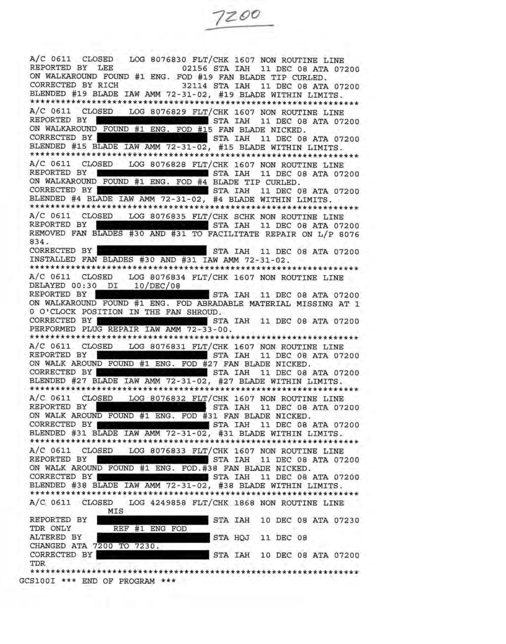
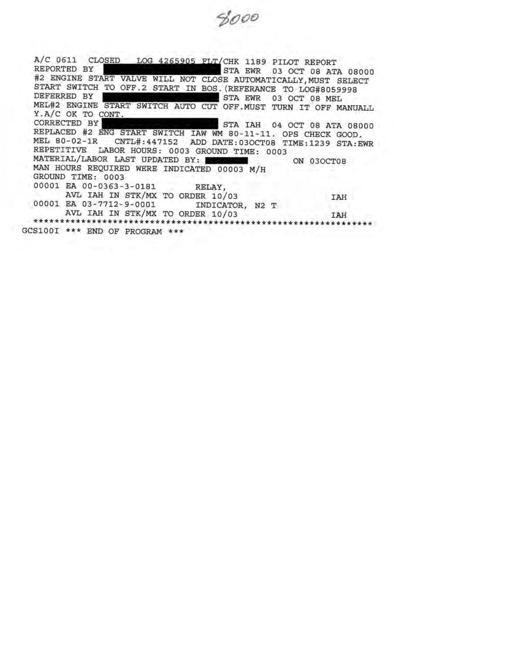
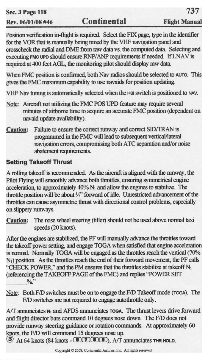
14 NTSB NO: DCA-09-MA ENGINE MAINTENANCE DISCREPANICES Continental Airlines provided list of discrepancies for Air Transport Association (ATA) codes related to the powerplants (APPENDIX 2) for the 90-days prior to the accident date. TABLE 2 shows those discrepancies and corrective actions taken. Table 2: 90-Day Engine History ATA Code Powerplant 7400 Ignition 7500 Air 7600 Engine Controls 7700 Engine Indicating 7800 Engine Exhaust ATA Description Discrepancy Reported Date None 7200 Turbine/Turboprop Engine Six fan blades nicked or curled on No.1 engine 12/11/08 Corrective Action Blended Correction Date 12/11/08 at station IAH 6 Fan case abradable material missing on No.1 engine 12/11/08 Repaired 7300 Engine Fuel and Control None Normal fuel filter check/replacement 7900 Engine Oil None Normal servicing 8000 Starting No. 2 engine start valve will not 10/03/08 Replace start close switch 12/11/08 at station IAH 10/04/08 at station IAH 5.0 FLIGHT DATA RECORDER INFORMATION The engine sequence of events is based on data from the flight data recorder (FDR) for the accident flight. The FDR was sent to the Safety Board Headquarters in Washington DC and was read out by the Vehicle Recorder Specialist. FIGURE 2 is a FDR plot for the accident flight and TABLE 3 provides a quick reference for the engine sequence. For reference purposes, time = zero seconds (T=0s) corresponds to the FDR MST (HH:MM:SS) of 18:17:39 and is designated as the time when the airplane is holding at the arrival end of Runway 34R before the engines are advanced from idle speed for takeoff (T/O). A reference times have been rounded to the nearest second. At T=0s, the throttles are at idle (0.7 and -1.4 throttle lever angle (TLA) respectively) resulting in fan speeds (designated as percent N1) for both engines of about 22% and 23% N1, respectively. At about T=+1s (MST 18:17:40), both throttles were advanced and the engine fan speeds started to increase. According to the Continental 737 Flight Manual takeoff thrust is set as follows: As the aircraft is aligned with the runway, the Pilot Flying (PF) will smoothly advance both throttles, ensuring symmetrical engine acceleration, to approximately 40% N1 and allow the engines to stabilize.after the engines are stabilized, the PF will manually advance the throttles toward the takeoff power setting and engage TOGA when satisfied that engine acceleration is normal. Normally TOGA will be engaged as the throttles reach the vertical position (70% N1) position. (APPENDIX 3) 6 IAH is Continental s facility located at the George Bush International Airport in Houston TX. 14 of 16
15 NTSB NO: DCA-09-MA-021 About three (3) seconds (MST 18:17:43) after both throttles were advanced (T=+4s) the airplane starts on its T/O roll. The acceleration of the engines was mismatched as they passed through 40% N1, even though the TLA for both were within about a percent of each other. According to the interview statement of the Captain (Flying Pilot), he commented that it [engines] was a little squirrelly getting to 40% N1 and as they were going to 70% N1 there was still a split in the motors but when pushed through to around 90% N1 he made sure the engines were pretty well matched [N1 speed]. The First Officer (Non-Flying Pilot) stated in his interview that the captain pushed the throttles to 40% N1 to make sure there were two good spools and that when the throttles were pushed to 70% N1, the captain engaged the auto-throttles but commented that the throttles were mismatched but that they spooled up to the takeoff power without any problems (See Operations/Human Performance Group Chairman s Factual report for complete details of the interview of the Captain and First Officer). At about T=+17s (MST 18:17:56), both fan speeds of both engines came together at about 70% N1 and from that point, continued to accelerate and were closely matched while they accelerated to T/O power. Both engines reached T/O power, about 90% N1 speed, at about T=+25s (MST 18:18:04) and remained at that level until about T=+40s (MST 18:18:19). According to the First Officer statement, the T/O power setting was to be 90.9% N1 based on their accuload program. At about T=+39s (MST 18:18:18), the airplane departed off the left side of the runway while both engines remained at about 90% N1. About two (2) seconds later (T=+41s/MST 18:18:20), the No. 1 engine experienced an uncommanded deceleration (no corresponding recorded TLA movement) to 58% N1 speed while the No. 2 engine fan speed remained at about 90%. At about T=+42s (MST 18:18:21) both throttles were brought back to idle and about one (1) second later (T=+43s/MST 18:18:22) the thrust reversers were deployed. The commanded reduction in power occurred about three (3) seconds after the airplane had departed the runway. According to the FDR data, the thrust reverser remained deployed to the end of the recording. The fan speed for the No. 1 engine continued to decrease after it reached 42% N1 at T=+42s but at a much slower rate than before until it reached its lowest recorded value of about 30% N1 at the end of the recording. The fan speed for the No. 2 engine continued to steadily decrease after the throttle lever was brought back to idle at T=+42s. Neither the No. 1 or 2 engine fan speed increased in value when the thrust reversers were deployed. TABLE 3: ACCIDENT SEQUENCE RELATIVE TO ENGINE PARAMETERS MST (HH:MM:SS) Time Pertinent Engine Parameters 18:17:39 T=0s TLAL = 0.7 and Engine 1 N1 speed 22% TLAR = -1.4 and Engine 2 N1 speed 23% 18:17:40 T=+1s Throttles advance and N1 speeds increase 18:17:43 T=+4s Airplane starts takeoff roll 18:17:56 T=+17s Engine N1 speeds match 18:18:04 T=+25s Engine 1 and 2 N1 speeds are about 90% 18:18:18 T=+39s Airplane departure left side of runway 18:18:20 T=+41s Engine 1 experienced an uncommanded deceleration Engine 1 fan speed drops to 58% 18:18:21 T=+42s Engine 1 N1 speed drops to 42% Both throttles retarded to idle Engine 2 N1 speeds starts to drop 18:18:22 T=+43s Thrust reversers on both engines deployed 15 of 16


16 NTSB NO: DCA-09-MA-021 FIGURE 2: DIGITAL FLIGHT DATA RECORDER DATA Jean-Pierre Scarfo Aerospace Engineer Powerplant Lead Engineer 16 of 16
17 APPENDIX 1: CONTINENTAL AIRLINES MAINTENANCE TIME AND CYCLE ENGINES TRACKING
18
19
20 APPENDIX 2: DISCREPANCIES HISTORY FOR THE 90-DAYS PRIOR TO THE ACCIDENT DATE
21
22
23
24
25
26
27
28
29

30
31
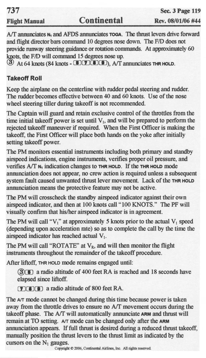
32 APPENDIX 3: CONTINENTAL AIRLINES 737 FLIGHT MANUAL TAKEOFF PROCEDURES
33
34
COMPONENT IDENTIFICATION
 This CFMI publication is for Training Purpose Only. The information is accurate at the time of compilation; however, no update service will be furnished to maintain accuracy. For authorized maintenance
CFM REGULATION THE POWER OF FLIGHT
 CFM56-3 3 REGULATION 1 CFM56-3 2 Speed Governing System Fuel Limiting System VBV VSV N1 Vs P Idling System HPTCCV N1 Vs Z N1 Vs T Main Tasks Additional Tasks Corrections MEC PMC CFM 56-3 ENGINE OPERATIONAL
AVIATION INVESTIGATION REPORT A02P0168 ENGINE POWER LOSS
 AVIATION INVESTIGATION REPORT A02P0168 ENGINE POWER LOSS TRANSWEST HELICOPTERS LTD. BELL 214B-1 (HELICOPTER) C-GTWH SMITHERS, BRITISH COLUMBIA, 10 NM S 07 AUGUST 2002 The Transportation Safety Board of
NATIONAL TRANSPORTATION SAFETY BOARD WASHINGTON, D.C.
 DOCKET NO. SA-516 EXHIBIT NO. 8A NATIONAL TRANSPORTATION SAFETY BOARD WASHINGTON, D.C. POWERPLANT GROUP CHAIRMAN'S FACTUAL REPORT by Gordon J. Hookey NATIONAL TRANSPORTATION SAFETY BOARD OFFICE OF AVIATION
Airframe vibration during climb, Boeing , AP-BFY
 Airframe vibration during climb, Boeing 747-367, AP-BFY Micro-summary: This Boeing 747-367 experienced airframe vibration during climb. Event Date: 2000-09-05 at 0420 UTC Investigative Body: Aircraft Accident
2018 Capabilities International Blvd Cincinnati, OH Phone: (513) Fax: (513)
 Fax: (513)") Aviation Repair & Overhaul FAA Certificate CL1R064K EASA Certificate 145.4358 CAAC Certificate F00100499 2018 Capabilities 9970 International Blvd Cincinnati, OH 45246-4898 Phone: (513) 870-6780 Fax: (513)
Aviation Repair & Overhaul FAA Certificate CL1R064K EASA Certificate 145.4358 CAAC Certificate F00100499 2018 Capabilities 9970 International Blvd Cincinnati, OH 45246-4898 Phone: (513) 870-6780 Fax: (513)
LM2500 BORESCOPE INSPECTION REPORT
 LM2500 BORESCOPE INSPECTION REPORT UC DAVIS CUSTOMER UNIT NAME/NUMBER: N/A ENGINE SERIAL NUMBER: 481-743 TCT SALES ORDER NUMBER: US9010290 DATE INSPECTED:11-29-2018 SERVICEABILITY AT DATE OF INSPECTION:
TCDS NUMBER E00078NE U.S. DEPARTMENT OF TRANSPORTATION REVISION: 3 DATE: April 12, 2011
 TCDS NUMBER E00078NE U.S. DEPARTMENT OF TRANSPORTATION REVISION: 3 DATE: April 12, 2011 FEDERAL AVIATION ADMINISTRATION GENERAL ELECTRIC COMPANY MODELS: TYPE CERTIFICATE DATA SHEET E00078NE GEnx-1B54 GEnx-1B58
Accident I nvest ig at ion
 ~ ~ SIN ~~ ~ Report ~ Rolls-Royce ~ - _. Accident I nvest ig at ion Rolls Royce Allison Engine Model 250-CZOB CAE 836707 (1) SIN CAE 836676 (2) Eurocopter Model BO 105 CBSS Registration N335T Temsco He1
An Additional Approach to Establishing the State of Operation of a Turbofan Engine During an Aircraft Accident
 An Additional Approach to Establishing the State of Operation of a Turbofan Engine During an Aircraft Accident Douglas Zabawa MO5843 Accident/Incident Investigator Pratt & Whitney Doug is an Accident and
AS 355 F1 S/N 5168 Factual Report Iao Valley Maui, Hawaii Date: July 21, 2000
 AS 355 F1 S/N 5168 Factual Report Iao Valley Maui, Hawaii Date: July 21, 2000 Note: Any and all references throughout this factual report to damage found during the wreckage inspection is not intended
AVIATION INVESTIGATION REPORT A07C0148 COLLISION WITH POWER LINE TOWER
 AVIATION INVESTIGATION REPORT A07C0148 COLLISION WITH POWER LINE TOWER CUSTOM HELICOPTERS LTD. BELL 206L-3 C-GCHG CRANBERRY PORTAGE, MANITOBA 09 AUGUST 2007 The Transportation Safety Board of Canada (TSB)
Fuse: On-wing engine inspection
 Figure 1 Assembled Commercial Turbofan Aircraft Engine -Trimetric View Figure 2 Assembled Commercial Turbofan Aircraft Engine Trimetric View - Partial Cutaway 1 1. Fan 2. Low Pressure Compressor (Booster)
CFM Technology. realizing the promise 50% LOWER NOX EMISSIONS. ANOTHER LEAP FORWARD FOR LEAP TECHNOLOGY.
 50% LOWER NOX EMISSIONS. CFM Technology realizing the promise ANOTHER LEAP FORWARD FOR LEAP TECHNOLOGY. Bill Brown General Manger CFM Marketing June 2010 CFM International Proprietary Information The information
Chromalloy. Borescope and Test Report. Prepared for. Triumph Air Repair A Triumph Group Company
 A Triumph Group Company Borescope and Test Report Prepared for Chromalloy Customer P.O.#: S2669 A.P.U. Model #: GTCP331-200ER A.P.U. Serial #: P-2796 A.P.U. Part #: 3800298-1 Triumph SRO #: S000013678
FINAL REPORT B ER, REGISTRATION 9V-SWB ENGINE FIRE 27 JUNE 2016 AIB/AAI/CAS.122
 FINAL REPORT B777-300ER, REGISTRATION 9V-SWB ENGINE FIRE 27 JUNE 2016 AIB/AAI/CAS.122 Transport Safety Investigation Bureau Ministry of Transport Singapore 27 FEBRUARY 2017 The Transport Safety Investigation
European Aviation Safety Agency
 European Aviation Safety Agency EASA TYPE CERTIFICATE DATA SHEET Number: IM.E.021 Issue: 05 Date: 03 January 2013 Type: General Electric Company CF34-10E Series Engines Variants CF34-10E2A1 CF34-10E5 CF34-10E5A1
European Aviation Safety Agency
 European Aviation Safety Agency EASA TYPE CERTIFICATE DATA SHEET Number : IM.E.026 Issue : 03 Date : 04 January 2013 Type : Engine Alliance LLC GP7200 series engines Variants: GP7270 GP7277 List of Effective
National Transportation Safety Board Washington, D.C
 E PLURIBUS UNUM NATIONAL TRA SAFE T Y N S PORTATION B OAR D National Transportation Safety Board Washington, D.C. 20594 Safety Recommendation Date: April 29, 2004 In reply refer to: A-04-34 and -35 Honorable
GENERAL The Honeywell model TFE731-40AR turbofan engine is a lightweight, two-spool, geared-stage, front-fan, jet engine.
 ENGINE GENERAL The Honeywell model TFE731-40AR turbofan engine is a lightweight, two-spool, geared-stage, front-fan, jet engine. The cross section of the engine is shown in Figure 7-71-1, page VII-71-3.
APS 2000 Shop Findings Report
 APU S/N : SP-E912042 AIRCRAFT REGISTRATION: EI-CZG APU P/N : 170101-106 CUSTOMER : Air One R/O N : 78202418 EVENT N : 1379 REVISION N : 685265 TSN : 16143 TSI : 2655 DATE OF REMOVAL: 18.04.07 CSN : 15386
TCDS NUMBER E37NE. REVISION: 13* DATE: May 1, 2014 CFM INTERNATIONAL, S.A. MODELS:
 TCDS NUMBER E37NE U.S. DEPARTMENT OF TRANSPORTATION FEDERAL AVIATION ADMINISTRATION TYPE CERTIFICATE DATA SHEET E37NE REVISION: 13* DATE: May 1, 2014 CFM INTERNATIONAL, S.A. MODELS: CFM56-5B1 CFM56-5B1/P
Reducing Landing Distance
 Reducing Landing Distance I've been wondering about thrust reversers, how many kinds are there and which are the most effective? I am having a debate as to whether airplane engines reverse, or does something
CF34 TURBOFAN ENGINE MAINTENANCE MANUAL LIFE LIMITS OF ROTATING ENGINE PARTS
 LIFE LIMITS OF ROTATING ENGINE PARTS 1. General. A. The FAA has approved service life-limit cycles (Airworthiness Limitations) for rotating parts installed in the CF34-1A/-3A/-3A2 turbofan engines. B.
LEAP-X Program Update
 LEAP-X Program Update 29 Oct 09 NYC CFM International Proprietary Information The information in this document is CFM Proprietary Information and is disclosed in confidence. It is the property of CFM International
V2527E-A5 ENGINE MINI-PACK
 V2527E-A5 ENGINE MINI-PACK Engine Serial Number: Total Time / Total Cycles: V10136 47,579:58 / 23,093 Time/Cycles Since Last 5,994 / 11,562 Shop Visit LHT 2012 Time/Cycles Since Last 5,994 / 11,562 Performance
MINI PACK N/A N/A N/A N/A FA0995 N/A
 MINI PACK ENGINE MODEL: PW150 BUILD SPEC: 885 TM SN: FA0995 TSN: 4,327.60 CSN: 4,194 TSO: CSO: TSHSI: CSHSI: N/A N/A N/A N/A RGB SN: FA0995 TSN: 4,327.60 CSN: 5,194 TSO: N/A CSO: N/A CONTENTS: - TMM Transport
DASSAULT AVIATION Proprietary Data
 F2000EX EASY 02-70-00 CODDE 1 PAGE 1 / 2 TABLE OF CONTENTS 02-70 02-70-00 TABLE OF CONTENTS 02-70-05 GENERAL Introduction Sources Engine location 02-70-10 DESCRIPTION Introduction Major components Operating
Singapore Airlines Flight 368 Engine Fire. Ng Junsheng Head (Technical)/Senior Air Safety Investigation Transport Safety Investigation Bureau
/Senior Air Safety Investigation Transport Safety Investigation Bureau") Singapore Airlines Flight 368 Engine Fire Ng Junsheng Head (Technical)/Senior Air Safety Investigation Transport Safety Investigation Bureau 3 rd Annual Singapore Aviation Safety Seminar 29 March 2017
Singapore Airlines Flight 368 Engine Fire Ng Junsheng Head (Technical)/Senior Air Safety Investigation Transport Safety Investigation Bureau 3 rd Annual Singapore Aviation Safety Seminar 29 March 2017
TYPE CERTIFICATE DATA SHEET
 TYPE CERTIFICATE DATA SHEET For Models: No. IM.E.102 for Engine GEnx Series Engines Type Certificate Holder GE Aviation One Neumann Way Cincinnati Ohio 45215 United States of America GEnx 1B GEnx 2B GEnx
REPAIR STATION MANUAL
 Propulsion Technologies International, LLC. 15301 S.W. 29th Street Miramar, Florida 33027 REPAIR STATION MANUAL APPENDIX A CAPABILITIES LIST Manual Control #: Electronic Assigned To: PTI LLC TABLE OF CONTENTS
DASSAULT AVIATION Proprietary Data
 FALCON 7X 02-70-05 CODDE 1 PAGE 1 / 6 GENERAL ACRONYMS LIST ACOC AGB APU A/T ATSV BOV CAS CB CL CMC CR DC DCU ECS EEC FADEC FBW FCU FF FOHE FSOV HP HPC HPT IGV ITT LP LPC LPT LRU MV N1 N2 PDU PLA PMA PMU
BULLETIN Serious incident involving BOEING MD-82 SE-DIK
 BULLETIN Serious incident 30-1-2013 involving BOEING MD-82 SE-DIK Certain report data are generated via the EC common aviation database Page 1 of 26 FOREWORD This bulletin reflects the opinion of the Danish
CFM56-7B POWER PLANT REMOVAL & INSTALLATION
 Task No: 737-71-00-00 NG Maint Prog Ref: BAL/BOE/11 Station: A/C Reg: Issue: 5 Date: NOV 2017 A.M.M. Ref: 71-00-02 Check: Aircraft Type CAA App Ref. UK.145.00112 Scheduled / Unscheduled Delete as applicable
Apparent fuel leak, Boeing , G-YMME
 Apparent fuel leak, Boeing 777-236, G-YMME Micro-summary: This Boeing 777-236 experienced an apparent fuel leak, prompting a diversion. Event Date: 2004-06-10 at 1907 UTC Investigative Body: Aircraft Accident
TEPZZ 55_5Z6A T EP A2 (19) (11) EP A2 (12) EUROPEAN PATENT APPLICATION. (43) Date of publication: Bulletin 2013/05
 (11) EP A2 (12) EUROPEAN PATENT APPLICATION. (43) Date of publication: Bulletin 2013/05") (19) TEPZZ _Z6A T (11) EP 2 1 06 A2 (12) EUROPEAN PATENT APPLICATION (43) Date of publication: 30.01.2013 Bulletin 2013/0 (1) Int Cl.: F02K 1/72 (2006.01) (21) Application number: 1217601.0 (22) Date of
(19) TEPZZ _Z6A T (11) EP 2 1 06 A2 (12) EUROPEAN PATENT APPLICATION (43) Date of publication: 30.01.2013 Bulletin 2013/0 (1) Int Cl.: F02K 1/72 (2006.01) (21) Application number: 1217601.0 (22) Date of
TYPE CERTIFICATE DATA SHEET
 TYPE CERTIFICATE DATA SHEET No. IM.E.096 for PW800 Series Engines Type Certificate Holder 1000 Marie Victorin Longueuil, Quebec J4G1A1 Canada For : TE.CERT.00052 001 European Aviation Safety Agency, 2016.
TYPE-CERTIFICATE DATA SHEET
 TYPE-CERTIFICATE DATA SHEET For Models: No. IM.E.102 for Engine GEnx Series Engines Type Certificate Holder GE Aviation One Neumann Way Cincinnati - Ohio 45215 United States of America GEnx-1B GEnx-2B
Full narrative available ERA11FA272 HISTORY OF FLIGHT
 NTSB Identification: ERA11FA272 14 CFR Part 91: General Aviation Accident occurred Saturday, April 30, 2011 in Indiana, PA Probable Cause Approval Date: 08/13/2014 Aircraft: ROBINSON HELICOPTER COMPANY
TYPE-CERTIFICATE DATA SHEET
 TYPE-CERTIFICATE DATA SHEET No. IM.E.093 for PW1100G-JM Series Engines Type Certificate Holder 400 Main Street East Hartford, CT 06118 United States of America For Models: PW1133G-JM PW1133GA-JM PW1130G-JM
National Transportation Safety Board Aviation Accident Final Report
 National Transportation Safety Board Aviation Accident Final Report Location: Dallas, TX Accident Number: Date & Time: 03/06/2002, 0715 CST Registration: N1425A Aircraft: Fokker F-28 MK-100 Aircraft Damage:
AVIATION INVESTIGATION REPORT A06O0141 LOSS OF CONTROL AND COLLISION WITH TERRAIN
 AVIATION INVESTIGATION REPORT A06O0141 LOSS OF CONTROL AND COLLISION WITH TERRAIN BEDE BD5-J C-GBDV OTTAWA / CARP AIRPORT, ONTARIO 16 JUNE 2006 The Transportation Safety Board of Canada (TSB) investigated
AVIATION OCCURRENCE REPORT
 AVIATION OCCURRENCE REPORT MAIN ROTOR BLADE SEPARATION IN FLIGHT RUPERT=S LAND OPERATIONS INC. HUGHES 369D (HELICOPTER) C-FDTN PROVOST, ALBERTA, 14 KM N 10 DECEMBER 1997 REPORT NUMBER The Transportation
AVIATION INVESTIGATION REPORT A03P0054 IN-FLIGHT ENGINE FAILURE
 AVIATION INVESTIGATION REPORT A03P0054 IN-FLIGHT ENGINE FAILURE WESTJET AIRLINES BOEING 737-200 C-FTWJ KELOWNA AIRPORT, BRITISH COLUMBIA 11 MARCH 2003 The Transportation Safety Board of Canada (TSB) investigated
TYPE-CERTIFICATE DATA SHEET
 Issue: 02 & LEAP-1C series engines Date: 11 March 2016 TYPE-CERTIFICATE DATA SHEET No. E.110 for Engine & LEAP-1C series engines Type Certificate Holder SA SA 2, boulevard du Général Martial Valin 75015
AVIATION OCCURRENCE REPORT A98Q0007 ENGINE FIRE AND CRASH ON TAKE-OFF
 AVIATION OCCURRENCE REPORT A98Q0007 ENGINE FIRE AND CRASH ON TAKE-OFF AIR NUNAVUT LTD. PIPER PA31-350 NAVAJO CHIEFTAIN C-FDNF SANIKILUAQ, NORTHWEST TERRITORIES 20 JANUARY 1998 The Transportation Safety
Rolls-Royce. Accident Investigation. & Engine Disassembly Inspection. Rolls-Royce Allison Model T63-A720 Engine CAE
 Rolls-Royce Accident Investigation & Engine Disassembly Inspection Rolls-Royce Allison Model T63-A72 Engine CAE 46157 I 1 3 Department of Public Safety, Utab Warren W. Seitzinger Accident Investigator
AA AIRCRAFT ACCIDENT INVESTIGATION REPORT PRIVATELY OWNED J A H
 AA2014-1 AIRCRAFT ACCIDENT INVESTIGATION REPORT PRIVATELY OWNED J A 1 2 0 H January 31, 2014 The objective of the investigation conducted by the Japan Transport Safety Board in accordance with the Act
MINI PACK BUILD SPEC. 885 ESN: FA0278 TSN: 15, CSN: 15,815 TSO: N/A CSO: N/A TSHSI: 2, CSHSI: 2,373 RGB SN. FA0278
 MINI PACK ENGINE Model: BUILD SPEC. 885 ESN: PW150A FA0278 TSN: 15,012.30 CSN: 15,815 TSO: N/A CSO: N/A TSHSI: 2,056.00 CSHSI: 2,373 RGB SN. FA0278 TSN: 15,012.30 CSN: 15,815 TSO: 3,596.40 CSO: 3,863 CONTENTS:
ANZSASI 2000 CHRISTCHURCH ENGINEERING ANALYSIS. Vlas Otevrel
 ENGINEERING ANALYSIS Vlas Otevrel 1 Garrett TPE 331 engine turbine failure The engine was fitted to a Metro II aircraft engaged in a freight run. Just after the top of descent, some 20 nm from destination,
ENGINE GROUND RUNNING
 B737 600/700/800/900 (CFM 56) ENGINE GROUND RUNNING Guide and Reference Sheets This publication is for TRAINING PURPOSES ONLY. This information is accurate at the time of completion. No update service
MTU Maintenance Dallas, Inc. Integrated Management System. MM 03D-03 Capability List Manual
 Chapter 0 Page 2 of 15 Revision: Initial Date: 01NOV2012 0.1 Table of Contents 0 Title Page... 1 0.1 Table of Contents... 2 0.2 List of Effective Pages... 3 0.3 Record of Revision... 4 0.4 Record of Temporary
DEPARTMENT OF TRANSPORTATION FEDERAL AVIATION ADMINISTRATION TYPE CERTIFICATE DATA SHEET NO. 1E8
 DEPARTMENT OF TRANSPORTATION FEDERAL AVIATION ADMINISTRATION 1E8 Revision 18 PRATT & WHITNEY AIRCRAFT TURBO WASP JT3D-1 JT3D-3 JT3D-1A JT3D-3B JT3D-1-MC6 JT3D-3C JT3D-1A-MC6 JT3D-7 JT3D-1-MC7 JT3D-7A JT3D-1A-MC7
CHAPTER 21 ENVIRONMENT CONTROL. Section Title Page
 CHAPTER 21 ENVIRONMENT CONTROL Section Title Page 21-00 Description........................................ 21.1 21-10 Ventilation........................................ 21.3 21-11 Nose Vent................................
Problem Statement. After losing hydraulic systems when engine #1 detached during takeoff.
 Problem Statement Report umber RCA-28-07-17-114 RCA Owner Chris Eckert Report Date 7/28/2017 RCA Facilitator Brian Hughes Focal Point: Crashed - 273 Fatalities When Start Date: 5/25/1979 End Date: 5/25/1979
FINAL REPORT HCLJ
 FINAL REPORT HCLJ510-2012-86 Serious incident Type of aircraft: Boeing MD-82 Registration: SE-DIL Engines: 2 P&W JT8D-217C Type of flight: Scheduled passenger, IFR Crew: 5 - no injuries Passengers: 130
5mm Crack Leading to an Engine Fire Lessons Learnt. Author: David Lim Principal Investigator, Transport Safety Investigation Bureau
 5mm Crack Leading to an Engine Fire Lessons Learnt Author: David Lim Principal Investigator, Transport Safety Investigation Bureau Synopsis On 27 June 2016, a Boeing 777-300ER aircraft departed Singapore
TYPE-CERTIFICATE DATA SHEET
 TYPE-CERTIFICATE DATA SHEET No. E.003 for Type Certificate Holder CFM International SA 2, boulevard du Général Martial Valin F-75724 Paris Cedex 15 France For Models: CFM56-5B SAC CFM56-5B DAC CFM56-5C
AIRCRAFT INCIDENT REPORT AND EXECUTIVE SUMMARY
 Section/division Accident and Incident Investigations Division Form Number: CA 12-12b AIRCRAFT INCIDENT REPORT AND EXECUTIVE SUMMARY Reference: CA18/3/2/0823 Aircraft Registration ZU-BBG Date of Incident
Rolls-Royce Corporation 501-D22 COMMERCIAL ENGINE BULLETIN (CEB) Technical Publications Index
 Technical Publications Index") Corporation 501-D22 COMMERCIAL ENGINE BULLETIN (CEB) Technical Publications Index May 1. 2018 72-- ENGINE 72--1001 Engine -- Reduction Gear Prop Recommended No Later Than 11--01--66 No. 2, 11--15--68 Brake
Corporation 501-D22 COMMERCIAL ENGINE BULLETIN (CEB) Technical Publications Index May 1. 2018 72-- ENGINE 72--1001 Engine -- Reduction Gear Prop Recommended No Later Than 11--01--66 No. 2, 11--15--68 Brake
Felix Du Temple de la Croix Monoplane 1857
 2 1 Felix Du Temple de la Croix Monoplane 1857 2 Thrust for Flight 3 Unpowered airplanes George Cayle s design (early 19 th century) Samuel P Langley s Airplane (late 19 th century) 4 Langley s Airplane
N A T I L T N S P R T A T I N S F E T. r i
 r i I N A T I 0 N A L T R A N S P 0 R T A T I 0 N S A F E T Y B 0 A R FILE NO. 4-0001 31RCRAFT INCIDENT REPORT CONTINENTAL AIRLINES, INC. MCDONNELL DOUGLAS DC-10, N68041 TUCSON, ARIZONA MAY 2, 1972 ADOPTED:
Cessna Citation Model Stats
 Cessna Citation Model Stats Cessna Citation Sovereign - Dimensions Length 63 ft 6 in (19.35 m) Height 20 ft 4 in (6.20 m) Wingspan 72 ft 4 in (22.04 m) Wing Wing Area Wing Sweep Wheelbase Tread 516 sq
Prime Aircraft, LLC Aircraft Sales & Acquisitions
 King Air Modifications Probably because the King Air is the most popular corporate turboprop every built and Beechcraft has manufactured over 6,000 units since 1964, many third party companies have come
Jump to Table of Contents
 Jump to Table of Contents PIPER AIRCRAFT CORPORATION PA-28R-201, CHEROKEE ARROW III SECTION 3 EMERGENCY PROCEDURES 3.3 EMERGENCY PROCEDURES CHECK LIST ENGINE FIRE DURING
CFM56-3 (FINAL_) 856A1027G01 Fixture, Lift - Compressor Rotor Stage 3 Disk And Blades 1 856A1028 Fixture 1
 856A1027G01 Fixture, Lift - Compressor Rotor Stage 3 Disk And Blades 1 856A1028 Fixture 1") 8100 Sweeney S/N STM014 1 107029435 BRKTs -3 Tooling 2 527241105 Fixture(combustion Chamber Fixture) 1 537241146 Fixture (combustion Chamber Fixture) 1 278114-1 CFM56-3 Fuel Pump Backlash Tool 1 301-360-005-0
8100 Sweeney S/N STM014 1 107029435 BRKTs -3 Tooling 2 527241105 Fixture(combustion Chamber Fixture) 1 537241146 Fixture (combustion Chamber Fixture) 1 278114-1 CFM56-3 Fuel Pump Backlash Tool 1 301-360-005-0
AVIATION INVESTIGATION REPORT A06O0150 ENGINE FAILURE COLLISION WITH TERRAIN
 AVIATION INVESTIGATION REPORT A06O0150 ENGINE FAILURE COLLISION WITH TERRAIN EXPEDITION HELICOPTERS BELL B206L (HELICOPTER) C-GSMZ SMOOTH ROCK FALLS, ONTARIO 21 JUNE 2006 The Transportation Safety Board
National Transportation Safety Board Aviation Accident Factual Report
 National Transportation Safety Board Aviation Accident Factual Report Location: Northport, AL Accident Number: Date & Time: 08/14/2016, 1115 CDT Registration: N447SA Aircraft: PIPER PA 31 Aircraft Damage:
Investigation Report. Bundesstelle für Flugunfalluntersuchung. Identification. Factual Information
 Bundesstelle für Flugunfalluntersuchung German Federal Bureau of Aircraft Accident Investigation Investigation Report 1X002-06 November 2011 Identification Type of Occurrence: Accident Date: 15 May 2006
REPORT A-023/2011 DATA SUMMARY
 REPORT A-023/2011 DATA SUMMARY LOCATION Date and time Site Monday, 11 July 2011, 21:00 local time San Carles de la Rápita (Tarragona) AIRCRAFT Registration Type and model Operator EC-JLB AIR TRACTOR AT-802A
SECTION 6-3 POWER PLANT
 SECTION 6-3 SYSTEMS DESCRIPTION Index Page General Description... 6-3-3 Engine Features... 6-3-4 Engine Indication System... 6-3-6 Power Plant Control... 6-3-10 Power Plant System Control... 6-3-12 Power
Airworthiness Directive
 Airworthiness Directive AD No.: 2018-0211 Issued: 28 September 2018 Note: This Airworthiness Directive (AD) is issued by EASA, acting in accordance with Regulation (EU) 2018/1139 on behalf of the European
TYPE-CERTIFICATE DATA SHEET
 TYPE-CERTIFICATE DATA SHEET No. E.062 for Type Certificate Holder Rolls-Royce plc 62 Buckingham Gate London SW1E 6AT United Kingdom For Models: RB211-22B-02, RB211-524-02, RB211-524B-02, RB211-524B-B-02,
Backgrounder. The Boeing ecodemonstrator Program
 Backgrounder Boeing Commercial Airplanes P.O. Box 3707 MC 21-70 Seattle, Washington 98124-2207 www.boeing.com The Boeing ecodemonstrator Program To support the long-term sustainable growth of aviation,
I. DISPATCH PLANNING & AIRCRAFT EXTERIOR CHECK
 SCHODACK AVIATION Page 1 of 10 I. DISPATCH PLANNING & AIRCRAFT EXTERIOR CHECK 1. Flight Planning 1. Aircraft requirements & preparation: Required aircraft documents: Airworthiness Certificate Registration
I. DISPATCH PLANNING & AIRCRAFT EXTERIOR CHECK
 SCHODACK AVIATION Page 1 of 10 I. DISPATCH PLANNING & AIRCRAFT EXTERIOR CHECK 1. Flight Planning 1. Aircraft requirements & preparation: 1. Required aircraft documents: 1. Airworthiness Certificate 2.
4.1 General Information. 4.2 Turning Radii. 4.3 Clearance Radii. 4.4 Visibility From Cockpit in Static Position. 4.5 Runway and Taxiway Turn Paths
 4.0 GROUND MANEUVERING 4.1 General Information 4.2 Turning Radii 4.3 Clearance Radii 4.4 Visibility From Cockpit in Static Position 4.5 Runway and Taxiway Turn Paths 4.6 Runway Holding Bay DECEMBER 2002
INSTRUCTIONS FOR CONTINUED AIRWORTHINESS
 Van Horn Aviation, L.L.C. 1510 W. Drake Drive Tempe, Arizona 85283 INSTRUCTIONS FOR CONTINUED AIRWORTHINESS ICA MANUAL Tail Rotor Blade Assembly 2062200-101/-301 Eligible for Installation on Model 206L4
IN-FLIGHT CHECK LIST B-17 Technical Session for Flight Engineers 11/18/2017 (with REVISION)
") IN-FLIGHT CHECK LIST B-17 Technical Session for Flight Engineers 11/18/2017 (with REVISION) Check Lists became an integral part of aviation following the tragic loss of Boeing 299 the prototype for the
IN-FLIGHT CHECK LIST B-17 Technical Session for Flight Engineers 11/18/2017 (with REVISION) Check Lists became an integral part of aviation following the tragic loss of Boeing 299 the prototype for the
REPORT IN-037/2008 DATA SUMMARY
 REPORT IN-037/2008 DATA SUMMARY LOCATION Date and time 4 September 2008; 15:38 UTC 1 Site Seville Airport AIRCRAFT Registration F-GLEC Type and model AEROSPATIALE SN-601 Corvette S/N: 30 Operator Airbus
AIRCRAFT GENERAL KNOWLEDGE (1) AIRFRAME/SYSTEMS/POWERPLANT
 AIRFRAME/SYSTEMS/POWERPLANT") 1 In flight, a cantilever wing of an airplane containing fuel undergoes vertical loads which produce a bending moment: A highest at the wing root B equal to the zero -fuel weight multiplied by the span
1 In flight, a cantilever wing of an airplane containing fuel undergoes vertical loads which produce a bending moment: A highest at the wing root B equal to the zero -fuel weight multiplied by the span
B737 NG Anti Ice & Rain
 B737 NG Anti Ice & Rain Introduction Thermal anti-icing (TAI), electrical anti-icing, and windshield wipers are the systems provided for ice and rain protection. The anti-ice and rain systems include:
National Transportation Safety Board Aviation Accident Factual Report
 National Transportation Safety Board Aviation Accident Factual Report Location: Northport, AL Accident Number: Date & Time: 08/14/2016, 1115 CDT Registration: N447SA Aircraft: PIPER PA 31 Aircraft Damage:
Prof. João Melo de Sousa Instituto Superior Técnico Aerospace & Applied Mechanics. Part B Acoustic Emissions 4 Airplane Noise Sources
 Prof. João Melo de Sousa Instituto Superior Técnico Aerospace & Applied Mechanics Part B Acoustic Emissions 4 Airplane Noise Sources The primary source of noise from an airplane is its propulsion system.
Preservation. A.1. Preservation for a Period of up to 30 Days. Pág. 2. Memoria ** ON A/C , , TASK
 Annex Pág. 2 Memoria A Preservation A.1. Preservation for a Period of up to 30 Days ** ON A/C 001-010, 012-099, 201-299 TASK 72-00-00-600-001 Preservation for a Period of up to 30 Days 1. Reason for the
Borescope Inspection Report MO-S-113 Taurus 70 CED Ie H
 Ie H Page 1 of 14 E Thermocouple 2 nd Stage Nozzle 2 nd Stage Blades 2 nd Stage Tip Shoe Blade Retaining Pins 3 rd Stage Nozzle 3 rd Stage Tip Shoe 3 rd Stage Blades External Variable Guide Vanes IGV 00
Rolls -Royce M250--C47B OPERATION AND MAINTENANCE TABLE 603. Inspection Checksheet. A/C Make/Model S/N Reg. No. TSN
 TABLE 603 Inspection Checksheet Owner Date A/C Make/Model S/N Reg. No. TSN Engine S/N TSN TSO This inspection checksheet is to be used when performing scheduled inspections. This form can be locally reproduced
AERONAUTICAL ENGINEERING
 AERONAUTICAL ENGINEERING SHIBIN MOHAMED Asst. Professor Dept. of Mechanical Engineering Al Ameen Engineering College Al- Ameen Engg. College 1 Aerodynamics-Basics These fundamental basics first must be
REPORT A-028/2007 DATA SUMMARY
 REPORT A-028/2007 DATA SUMMARY LOCATION Date and time Thursday, 21 June 2007; 18:40 local time 1 Site Abanilla (Murcia) AIRCRAFT Registration EC-HYM Type and model BELL 412 Operator Helicópteros del Sureste,
AVIATION INVESTIGATION REPORT A00P0208 MAIN-ROTOR BLADE FAILURE
 AVIATION INVESTIGATION REPORT A00P0208 MAIN-ROTOR BLADE FAILURE PRISM HELICOPTERS LTD MD HELICOPTER 369D, C-GXON MT. MODESTE, BRITISH COLUMBIA 5 NM NW 31 OCTOBER 2000 The Transportation Safety Board of
Technical report A-054/1999 APPENDICES
 Technical report A-054/1999 APPENDICES 95 Technical report A-054/1999 APPENDIX A Photographs, figures and graphs 97 Figure 1 Figure 2 MAIN WRECKAGE Aircraft Figure 3.1 Aerial View Figure 3.2 Main Wreckage
 LEAP LEAP overview THE LEAP ENGINE REPRESENTS THE OPTIMUM COMBINATION OF CFM INTERNATIONAL S UNRIVALED EXPERIENCE AS THE PREFERRED ENGINE SUPPLIER FOR SINGLE-AISLE AIRCRAFT AND ITS 40+ YEAR INVESTMENT
REPORT IN-042/2006 DATA SUMMARY
 REPORT IN-042/2006 DATA SUMMARY LOCATION Date and time Friday, 14 July 2006; 13:15 h local time 1 Site Borjas Blancas (Lleida) AIRCRAFT Registration Type and model Operator EC-JCQ TECNAM P2002-JF Private
CHAPTER 6 POWERPLANT
 Section Title CHAPTER 6 POWERPLANT 6.000 Powerplant And Related Systems................................ 6.1 6.001 Introduction............................................ 6.1 6.002 Description.............................................
Engine Finance Rountable Managing an engine. Stephane Garson, General Manager Marketing. 1 st May 2008, New York
 Engine Finance Rountable Managing an engine Stephane Garson, General Manager Marketing 1 st May 2008, New York Two Strong Aerospace Leaders Behind CFM CFM International is a Joint Company of Snecma & General
Aircraft Maintenance Prof. A.K Ghosh Prof. Vipul Mathur Department of Aerospace Engineering Indian Institute of Technology, Kanpur
 Aircraft Maintenance Prof. A.K Ghosh Prof. Vipul Mathur Department of Aerospace Engineering Indian Institute of Technology, Kanpur Lecture - 11 Inspection of Aircraft So, we are now on Cessna 206 edge
AVIAT AIRCRAFT INC. P.O. Box South Washington Afton, WY USA Fax:
 DATE: 18 December 2000 REVISION: Orig. AIRCRAFT: PITTS SPECIAL P.O. Box 1240 672 South Washington Afton, WY 83110 USA 307-886-3151 Fax: 307-885-9674 aviat@aviataircraft.com SUBJECT: Propeller Accumulator
2
 2 3 4 5 FOD Forgeign Object Damage M.Wirth 21-02-2017 2017 Rolls-Royce Deutschland Ltd & Co KG The information in this document is the property of Rolls-Royce Deutschland Ltd & Co KG and may not be copied
AIRCRAFT ACCIDENT REPORT AND EXECUTIVE SUMMARY
 Section/division Accident and Incident Investigation Division Form Number: CA 12-12a AIRCRAFT ACCIDENT REPORT AND EXECUTIVE SUMMARY Reference: CA18/2/3/8452 Aircraft Registration ZS-RJL Date of Accident
A1-F402B-MMI February 2003 Page A
 1 February 2003 Page A NUMERICAL INDEX OF EFFECTIVE WORK PACKAGES/PAGES List of Current Changes Original...0...1 February 2003 (IRACs 4 thru 8 Inc.) Only those pages assigned to the manual are listed in