Propulsorss. The Emerson. the Emerson. conditions (1. a de- designed for. conventional. from. 35 %. This was encourage. going astern, For the early
|
|
|
- Marjory Barker
- 6 years ago
- Views:
Transcription


 as well as the effect of")


1 Third International Symposium on Marine Propulsorss smp 13, Launceston, Tasmania, Australia, May 2013 Axiom Propeller tests in the Emerson Cavitationn Tunnel M. Atlar, 1 R. Sampson 2 1, K.C. Seo, A. Watts 3 & D. Watts 3 1 Emerson Cavitation Tunnel, University of Newcastle, UK 2 Science & Technology Corporation, Columbia, MD, USA 3 Axiom Propellers, Northamptonshire, UK ABSTRACT The Emerson Cavitation Tunnel at Newcastle University recently conducted a series of open water model testss on a unique 3 bladed propeller, commercially known as Axi- market. The purpose of the tests was to measure thee per- om Propeller, intended for the narrow-boat and sailboat formance and cavitation characteristics of this propeller with a bi-directional thrust capability making use of its skew symmetric blade sections, and to compare itss per- in formance to an earlier variant of the design, also tested the Emerson Cavitation Tunnel by Seo et al (2010). The study of the propeller included open water and stopping conditions (1 st & 2 nd quadrant) as well as the effect of cavitation over a range of achievable advance coeffi- a de- cients. This paper presents the design background, scription of the test set-up; the results of the multi- to- quadrant performance tests at atmospheric condition gether with a short review of the cavitation observations for this unusual propeller. Figure 2 shows an Axiom propeller design fitted to a narrow boat. The unique propeller performs well in low speed, sailing in restricted waters, all often at typical Froude numbers of o F n = 0.12 or lower. Advocates for the Axiom design claim improved handling, greater fuel efficiency, reduced prop-walk and impressive stopping performance for their vessels.. This is important as the vessel operates att very low speed in restricted canal wa- terways where manoeuverability and stopping ability are the key performance requirements rather than attainable speed. Keywords Skew symmetric blade section, open water performance, cavitation, experimental study. 1 INTRODUCTION The Axiom propeller is a unique 3 bladed propeller that is designed for the low speed / lightly loaded, narroww boat and sailboat market. The design differs from the more conventional propeller geometry of aerofoil type propeller sections in-so-far as it has an unusual s type skew- shown in Figure 1. This symmetry allows the propeller to symmetric blade section with spade like blades outlines generate the same amount of thrust going ahead as itt does going astern, one of its key design features, enablingg it to be a bi-directional thrust propeller. Figure 1. The Axiom propeller showing the t unusual s type section on a 3 blade propeller Figure 2. Axiom propeller fitted to a narrow-boat The design for the Axiom propeller was developedd somewhat heuristically and the parent design suffered from a low open water efficiency of around 35 %. This was encourage ing given that no experimentall testing or validation in a research facility had h been performed adopting a trial and errorr style of optimisation; alll of which encouraged the designers to pursue further optimisation. For the early Axiom design, trials were conducted in a simple manner as reported by Langley (2009). For these trials two m (49 ft) narrow boats of identical design and a powering weree used; the first fitted withh a conventional propeller, the second with the Axiom propeller. The boats were run along the same stretch s of canal approximately 100 m apart. The trials were conducted by running the boats at the same shaft rotational rate (rpm) and timed between various destinations. The canals were typically shallow, with bank and depth effects; the conditionss of the hulls weree not specified. A series of f return runs were also per- formed in an effort to reduce the effects of current c on the 168


 and the Axiom")


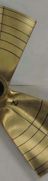


2 results. However despite this rudimentary trials proce- When compared to the conventional design the Axiom propeller showed an increase in speed and handling for dure, the tests showed the benefit of the t Axiom design. the same rpm but with a drop in vibration. Figure 3 shows the boats during the trial at the same rpm. Following this introduction in Section 1, Section 2 gives the test set-up andd Section 3 gives the results of the open water performance tests including the first two quadrant data for this propeller. Sectionn 4 gives a short review of the cavitation observations in the 1 st and 2 nd quadrant and Section 5 draws conclusions from the results. Figure 3. Performance trials with the regular propeller (top) and the Axiom propeller (bottom) att the same rpmm The trials team noted the different wave patternss and wake created by the various designs, visible in Figure 3, but failed to recognise that the wave patterns were speed dependent and would change from favourable to unfa- other factors. The trials team also observed that thee dif- vourable depending upon Froude number, and several fering wave characteristics caused the vessel to be drawn towards the canal wall more for the larger wave system requiring more use of the tiller to maintain heading.. This was clearly a speed, and hence wave characteristic, and something that would have been eliminated fromm the comparison if the forward speed were to have been matched rather than the rpm. Finally, the two test propel- lers were also very different in their stopping ability.. The conventional propeller stopped the boat from walking pace in 1 ship length; with the Axiom itt was half of that. Whilst the design is appealing for it s manoeuvring char- un- acteristics, its cavitation and loading potential weree known beyond these simplistic trials. To fully understand the capabilities and the limitations of the blade design a series of scientific trials and investigations were required. In collaboration with the Emerson Cavitation Tunnel, Axiom Propellers optimised their blade design to reduce the spade like blade outline shown in Figure 4 to a more conventional Kaplan geometry shown in i Figure 5. It was hoped that the new design could be more efficient and operate at higher speedss whilst stilll utilising the bi- the directional thrust capability to the full. To understand limitations of this new design, a further series of model tests were performed to assess the improvements inn performance due to these design changes. Figure 4. The original Axiom propeller design Figure 5. The optimised Axiom propellerr design 2 IMPLEMENTATION OF EXPERIMENT The propeller tests were conducted in the Emerson Cavi- tation Tunnel (ECT) in May 2012 as reported by Sampson et al (2012). Thee ECT is a closed circuit depressurisedd tunnel located within w the University of Newcastle. A schematic of the tunnel circuitt is given in Figure 6. The ECT has a measuring section of 3.2m x 1.2m x 0.8m; a contraction ratio of o 4.274:1 andd is thereforee considered a medium sized facility. During recent years, numerous improvements too the instrumentation equipment and measuring sectionn have takenn place all ncreasing the capabilities of thee facility. In n 2008, the tunnel was up- graded with the installation of f a new measuring section, 169

3 guide vanes, honeycomb, quick degassing system and automated control system. The basic specifications for the tunnel are given in Table 1 whilst the details of this recent upgrading was reported in Atlar (2011) Figure 6. Emerson Cavitation Tunnel schematic. Table 1. Emerson Cavitation Tunnel specification Tunnel Emerson Cavitation Tunnel Facility type Vertical, closed Circulating Test section (LxBxH) 3.10m x 1.22m x 0.81m Contraction ratio Drive system 4 Bladed axial flow impeller Main pump power 300 kw Impeller diameter 1.4 m Maximum velocity 8 m/s (15.5 knots) Abs. pressure range 7.6 kn/m2 to 106 kn/m2 Cavitation number 0.5 (min) to 23 (max) Table 2. Propeller Axiom I Characteristics Scale 1:1 Number of blades 3 Diameter 0.3m Pitch / diameter ratio at r/r = Blade area ratio 0.7 Direction of rotation Right Table 3. Propeller Axiom II Characteristics Scale 1:1 Number of blades 3 Diameter 0.3m Pitch / diameter ratio at r/r = Blade area ratio 0.5 Direction of rotation Right The propeller tests were performed using a large H45 Kempf and Remmers open water dynamometer at atmospheric conditions. The propeller used in the experiment was a full-scale model of the Axiom propeller shown previously in Figure 5, designated Mark II; the original propeller shown previously in Figure 4 being designated Mark I. The model propeller was manufactured by Axiom Propellers in Bronze to fit a 1 ¼ dynamometer shaft. The propeller was 300 mm diameter with a pitch to diameter ratio (P/D) of 1.0 and a blade area ratio (BAR) of 0.5. Table 3 gives the main particulars of the propeller whilst Figure 7 shows the propeller prior to the test. In order to assess the efficiency performance of the propeller, open water tests at atmospheric condition were conducted. The tests were performed to cover a practical range of advance coefficient (J) varying between J = 0.30 and J = 0.75 under normal atmospheric conditions. For the tests the tunnel water speeds were held at 3.0 m/s and 4.0 m/s, whilst the rotational rate of the propeller was varied to cover the above range of J values. Finally the data was non-dimensionalised using standard ITTC (2002) test procedures. The equations used in the analysis for the advance coefficient (J), thrust coefficient (K T ), torque coefficient, (K Q ), and open water efficiency (η o ), are given in Equations 1 ~ 4: Figure 7. The Axiom propeller prior to testing Finally the test parameters were set using ECT procedures. The air content was held between 25-35%; the model scale Reynolds number gave a value typically Re = 1 x10 6, given in Equation 5, and the cavitation number based on the free stream flow velocity (V x ) of the tunnel was selected for practical convenience as shown in Equation 6. Advance coefficient = Thrust coefficient K T = Torque coefficient K Q = Open water efficiency (1) T ρn 2 D 4 (2) Q ρn 2 D 5 (3) = (4) 170
, Q is the torque (Nm) of the propeller, D is the propeller diameter (m) A E is the t expandedd area (m 2 ), A 0 is the disk area (m 2 ), p is the absolute a pressure at the")

 or astern (anti-clockwise) directions while the direction of the tunnel flow was kept inn the same (ahead) direction.")
 being generat- ed from the former owing to the skew")
 defined in Equation 7.")
 2 (5) (6) It should be notedd that when β = 0 o or β = 360 o then this defines the aheadd bollard pulll condition and when β = 180 o this corresponds to the astern bollard pull situation.")
 and torque coefficient (C Q ) for this analysis are defined d using g the resultantt velocity and are given in Equations 8 and 9.")
4 Reynolds number Cavitation number R e = A E A0 Z nd2 ν p e σ v = 1 2 ρ V x Where, V is the tunnel free stream water velocity (m/s), n is the rotational speed of the propeller (rps),( T is thrust of the propellerr (N), Q is the torque (Nm) of the propeller, D is the propeller diameter (m) A E is the t expandedd area (m 2 ), A 0 is the disk area (m 2 ), p is the absolute a pressure at the propellerr disk (Pa); e is the vapourisation pressure (Pa), ν is the kinematic viscosity (cm 2 /s) and ρ is thee den- sity of the tunnel solution (kg/m 3 ). In addition to the open water tests, which represent the first quadrant performance of the propeller, i.e. thee pro- advance velocity, the additional 3 quadrants were re- peller working with positive rotational speed and positive quired. The 4 quadrant data therefore represents anyy flow condition experienced by a propeller during manoeuvring. During thesee tests the propeller may be rotated inn the ahead (clockwise) or astern (anti-clockwise) directions while the direction of the tunnel flow was kept inn the same (ahead) direction. The physical orientation of the propeller could have been changed back to front to simu- described below. However given the symmetrical s nature of the design, only the first two quadrants were actually required the latter two (3 rd & 4 th quadrant) being generat- ed from the former owing to the skew symmetric nature of the late the appropriate quadrant according to the notation data. In the case of a fixed pitch propeller it is conventional to define the four quadrants based on an advance angle (β) defined in Equation 7. Using this nomenclature the 4 quadrants can be easily identified and are given in Table 4. ( x ) 2 (5) (6) It should be notedd that when β = 0 o or β = 360 o then this defines the aheadd bollard pulll condition and when β = 180 o this corresponds to the astern bollard pull situation. For β = 90 o and β = 270 o, these positions relate to the condition when the propeller iss not rotating and is being dragged ahead orr astern through the water respectively. The thrust coefficient (C T ) and torque coefficient (C Q ) for this analysis are defined d using g the resultantt velocity and are given in Equations 8 and 9. Thrust coefficient T C T = π 8 ρ V 2 a + 0.7πnD ( ) 2 D Torque coefficientt T C Q = π 8 ρ V 2 a + 0.7πnD ( ) 2 D (8) D 2 (9) D 3 3 RESULTS AND DISCUSSION The Axiom (Mark II) propeller showed a marked im- provement in terms of performance, cavitation and noise over the previouss design (Mark I). To understand this increase the open water performance, 4 quadrant data and the cavitation patterns were analysed and compared to the original propeller. 3.1 Open water w analysis A plot of the openn water performance of the Axiom Mark II propeller is given in Figure e 8. The dataa is given for thrust (K T ), torque (10K Q ) andd efficiency (η( o ) for all of the experimental points gathered. The data has been subsequently processed using least squares fit f to give the backbone curves for f each of these variables. Advance angle V β = tan 1 a 0. 7πnD (7) Table 4: The 4 quadrant propeller performance data 2 nd quadrant: 1 st quadrant: (Stopping in ahead) Going ahead Advance speed ahead Advance speed aheadd Rotational speed astern Rotational speed ahead Adv. angle 90 < β 180 Adv. angle 0 β 90 3 rd quadrant: 4 th quadrant: Reversing Stopping in astern Advance speed astern Advance speed astern Rotational speed astern Rotational speed ahead Adv. angle 180 < β 270 Adv. angle 270 < β 360 Figure 8. Open water plot for r Axiom Mark II propeller The Mark II Axiom propellerr provided very repeatablee test data with onlyy small test-to-test variation. The maxi- mumm efficiency was w 53.7% at J = When this was compared to the Mark M I propeller it is clear that the reduc- tion in blade area and tapered blade outline as opposed to the plan form (square shape) between the two designs has had a significant positive effect on the efficiency. A comparison of thee open water plots is given in Figure 9, it 171


 to J = 0.")


 and the Axiom Mark II (faired)")

 have h been modified")

, propeller shaft")

")


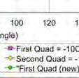


5 is clear that the new design was approximately 63% more efficient. The new propeller also hass a wider range of achievable advance coefficients due to t the increase in pitch ratio from P/D = 0.86 to P/D = 1.0 changing the operating point for the propeller from J = 0.35 (cavitating) to J = (non-cavitating). This helped the Mark II propeller operate in a virtually cavitation free condition at the design point. the Axiom propeller for stopping and reversing as well as controlling the course keepingg in both directions, ahead and astern, with almost similar performance. The smalll discontinuities around β = 0 o, 90 o, 180 o, 270 o and 360 o are due to the physical limitations of the facility. These val- ues can be obtained from the values around their vicinity by simple interpolation. Figure 9. Comparison of open water plots for the Axiom Mark I (old) and the Axiom Mark II (faired) propeller. Figure 11. Multi-quadrant data of the Mark I propeller demonstrating the skew symmetry the 3 rd and 4 th plots (180 o 360 o ) have h been modified and overlaid 3.2 Multi-quadrantt tests The Multi-quadrant tests were conducted by appropriately varying the tunnel flow speed (V), propeller shaft speed (n), direction of shaft speed (clockwise and anti- via the relative position of the propeller with respect to clockwise) and direction of tunnel flow (ahead and astern) flow as outlined in Section 2. Figure 10 shows the results of the Mark I Axiom propeller presented in the classical four quadrant notation of C T and 10C Q against a β. Figure 10. Four quadrant data for the Mark 1 propeller The Axiom propeller has symmetric characteristics in almost all quadrants, as well as the skew symmetry of C T and C Q curves; this is not the case for the conventional propellers, which are usually optimised for the forward motion only. Obviously this is a favourable attribute for Figure 12. Comparison of the Axiom Mark I and Mark II multi-quadrant propeller data The values in Figure 10 can be re-plotted to take ad- vantage of the symmetrical s sections of the t propeller. Figure 11 shows the re-plottedd results. In this figure the Axiom Mark 1 propeller data has been shown to be skew symmetric, which implied for this particular propeller thatt only the first two quadrants needed to be ested with the remaining data obtainable by simple arithmetic manipula- tion. When the results from the Mark II Axiom propellerr are overlaid on the plot, shown in Figure 12, it is clear that the Mark II Axiom A propeller performs slightly s differ- ently with the majority of the curve outside the Mark I curve and the remaining 60 o of each quadrant inside. 3.3 Cavitation observations The cavitation patterns on the Mark II were similar to the first version of the propeller. The S type section is not ideally suited to heavily h loadedd conditions as a it promotes significant levels cavitation midd chord on the blade. The 172

6 cavitation inception began at approximately J = At J = 0.45 the tip vortex cavitation was a thin fully developed filament. At the leading edge between r/r = 0.7 ~ 0.9 a small area of sheet cavitation began to develop. This sheet cavity would transit the chord as the J value was reduced to eventually combine with the tip vortex cavitation. However in this condition it extended approximately 5% of the chord. At J = 0.40 the cavitation types present on the blade began to stabilise. The sheet cavitation covered 10% of the blade mostly focused around r/r = 0.8. However at this condition the end of the sheet cavity was becoming unsteady and small wisps of erosive cloud cavitation could be detected. The tip vortex remained in position but increased in strength. By J = 0.35 the sheet cavitation covered half of the chord for each blade. The unsteady nature of the after part of the cavity was generating significant levels of mist cavitation, which would most certainly be erosive. The sheet cavity was also influencing the tip vortex cavitation, which too was starting to become unsteady and break down. At J = 0.30, the sheet cavitation covers more than 90% of the blade at r/r = 0.8 and has begun to interact with the tip vortex cavitation. For this condition both the sheet and tip vortex cavitation are starting to break down and generate unsteady cavitation coupled with large amounts of erosive cloud cavitation. Cavitation observations were made with the propeller in the 1 st and 2 nd quadrant runs at atmospheric condition. The results are given in Figure 13 for a range of J values (J = 0.30 ~ J = 0.45). For the tests, the tunnel was open to atmosphere; the flow velocity was kept constant (σ v = 23), whilst the shaft rpm was varied to cover the range of operational conditions. J = 0.30 J = 0.35 J = 0.40 J = 0.45 Figure 13. Open water images (J = 0.30 J = 0.45) 173


7 Figure 14. Comparison of Axiom I (Left) and Axiom II (Right) for J = 0.30 and V = 3.0 m/s Figure 14 shows a comparison of the Mark I and the Mark II Axiom propellers from the different tests. From this figure it is clear that the Mark II is more heavily loaded at the same test condition, whereas the Mark I with its smaller pitch ratio is still transitioning into unsteady cavitation range. The Mark II however, will typically operate cavitation free at J = 0.55 the tentative design point. Finally Figure 15 shows the cavitation patterns for the multi-quadrant tests. In this figure it is easy to see the conventional cavitation pattern associated with first quadrant testing at β = 5 o however as the quadrant changes to the second quadrant by β = 175 o, where the flow is forward and the propeller reversing the cavitation switched to the back of the propeller (suction side), generating tremendous levels of noise and vibration. This condition would represent a transitory phase in stopping a vessel and not a steady state condition. Figure 15. Cavitation images from the multi quadrant tests 6. CONCLUSIONS This paper presented the cavitation tunnel tests for a 300mm diameter, 3 bladed bi-directional thrust propeller. These tests were conducted to verify the propeller s efficiency the multi-quadrant performance and cavitation characteristics. Based on the tests it was found that: Maximum efficiency of the Mark II Axiom propeller was measured at 53%; this was obtained during the first quadrant / open water test. Bearing in mind the differences in the P/D, BAR and outline shapes, the Mark II version of the propeller can provide 63% more efficiency over the Mark I version under similar conditions. Useful, comparative multi-quadrant data for the two Axiom propellers are presented. The data reflected the symmetric feature of the propellers. The ahead and astern (thrust and torque) performance of this bi-directional thrust propeller was 174
8 shown to have skew symmetry requiring only 2 quadrants to be tested. In the first quadrant, the main cavitation patterns were a strong steady tip vortex and leading edge sheet cavitation at the suction (back) side of the blades. The extent and interaction of these cavities increased with reduced J value. The mid chord sheet cavitation was potentially erosive however the design point for this propeller is well away from the cavitation condition. The Mark II Axiom propeller with the new tapered outline shape would benefit from the inclusion of a duct to supress cavitation and increase performance further. However the Axiom Mark II design, for the condition shown, does not operate in a cavitation zone. REFERENCES Atlar M. (2011) Recent upgrading of marine testing facilities at Newcastle University.AMT 11, the second intl. conference on advanced model measurement technology for the EU maritime industry, Newcastle University, UK, 4 6 April. ITTC (2002), Testing and Extrapolation Methods Resistance Test, International Towing Tank Conference, Technical report of the resistance committee, Procedure No Langley, M. (2009) Tried & tested Axiom Propeller, Waterways World, WW Magazines UK, July Sampson, R., Atlar, M., Politis, G. (2012) AXIOM Mark II Propeller: Multi - quadrant open water tests, School of Marine Science and Technology, Newcastle University, Technical Report, MT/CT Seo, K.C., Atlar, M., Wightman-Smith, J., and Paterson, I. (2010) Multi-quadrant open water tests with an Axiom propeller in the Emerson Cavitation Tunnel. School of Marine Science and Technology, Newcastle University, Technical Report, MT/2010/00 175
Effect of cavitation during propeller ice interaction. Rod Sampson Emerson Cavitation Tunnel, University of Newcastle, UK
 Effect of cavitation during propeller ice interaction Rod Sampson Emerson Cavitation Tunnel, University of Newcastle, UK ITTC Specialist Committee on Ice Podded Propulsor Performance in Ice Papers published
On the full scale and model scale cavitation comparisons of a Deep-V catamaran research vessel
 Fourth International Symposium on Marine Propulsors SMP 15, Austin, Texas, USA, June 2015 On the full scale and model scale cavitation comparisons of a Deep-V catamaran research vessel R. Sampson, S. Turkmen,
Design and Hydrodynamic Model Test of Mini Submarine Propeller with High Efficiency and Low Cavitation
 EPI International ournal of Engineering pissn 2615-5109 Volume 1, Number 2, August 2018, pp. 59-64 eissn 2621-0541 DOI: 10.25042/epi-ije.082018.09 Design and Hydrodynamic Model Test of Mini Submarine Propeller
Advanced Design of a Ducted Propeller with High Bollard Pull Performance
 First International Symposium on Marine Propulsors smp 09, Trondheim, Norway, June 009 Advanced Design of a Ducted Propeller with High Bollard Pull Performance Tadashi Taketani 1, Koyu Kimura 1, Norio
Development of Contra-Rotating Propeller with Tip-Raked Fins
 Second International Symposium on Marine Propulsors smp, Hamburg, Germany, June 2 Development of Contra-Rotating Propeller with Tip-Raked Fins Yasuhiko Inukai IHI Marine United Inc., Tokyo, Japan ABSTRACT
Reliable, Silent, Efficient. Voith Linear Jet
 Reliable, Silent, Efficient. Voith Linear Jet 1 A New Propulsion Standard. The Voith Linear Jet (VLJ) combines the best elements of two existing technologies conventional screw propellers and water jets.
CFD on Cavitation around Marine Propellers with Energy-Saving Devices
 63 CFD on Cavitation around Marine Propellers with Energy-Saving Devices CHIHARU KAWAKITA *1 REIKO TAKASHIMA *2 KEI SATO *2 Mitsubishi Heavy Industries, Ltd. (MHI) has developed energy-saving devices that
A Development of a Propeller with Backward Tip Raked Fin
 Third International Symposium on Marine Propulsion smp 13, Tasmania, Australia, May 2013 A Development of a Propeller with Backward Tip Raked Fin Yasuhiko Inukai Japan Marine United Cooperation, Tokyo,
IMO NOISE FROM COMMERCIAL SHIPPING AND ITS ADVERSE IMPACTS ON MARINE LIFE. Reducing underwater noise pollution from large commercial vessels
 INTERNATIONAL MARITIME ORGANIZATION E IMO MARINE ENVIRONMENT PROTECTION COMMITTEE 59th session Agenda item 19 MEPC 59/19/1 6 May 2009 Original: ENGLISH NOISE FROM COMMERCIAL SHIPPING AND ITS ADVERSE IMPACTS
Abstract. 1 Introduction
 Effect of stern tunnel height on propulsive efficiency of inland vessels J. Kulczyk, P. Zaj^c Institute ofmachine Construction and Operation, Technical University of Wroclaw Wybrzeze Wyspianskiego 27,
Moving ahead powerfully: MAN Diesel & Turbo optimizes the efficiency of ship propellers using cutting-edge CFD simulation methods
 Moving ahead powerfully: MAN Diesel & Turbo optimizes the efficiency of ship propellers using cutting-edge CFD simulation methods Keun Woo Shin MAN Diesel & Turbo Ulrich Feldhaus Feldhaus Marketing & Datentechnik
A Breakthrough in Waterjet Propulsion Systems
 Doha International Maritime Defence Exhibition and Conference DIMDEX 2008, Qatar, March 2008 A Breakthrough in Waterjet Propulsion Systems Dr Norbert Bulten Wärtsilä Propulsion Netherlands *, Drunen, The
A Framework for Energy Saving Device (ESD) Decision Making
 Decision Making") A Framework for Energy Saving Device (ESD) Decision Making Authors: J. H. de Jong, G.J.D. Zondervan Presented by J.H. de Jong Contents 1. Background 2. Propulsion improvement 3. Practical application of
A Framework for Energy Saving Device (ESD) Decision Making Authors: J. H. de Jong, G.J.D. Zondervan Presented by J.H. de Jong Contents 1. Background 2. Propulsion improvement 3. Practical application of
A modern approach to the representation and use of the KCA systematic propeller series
 Third International Symposium on Marine Propulsors smp 13, Launceston, Tasmania, Australia, May 2013 A modern approach to the representation and use of the KCA systematic propeller series G.H.G Mitchell,
EFFECT OF SURFACE ROUGHNESS ON PERFORMANCE OF WIND TURBINE
 Chapter-5 EFFECT OF SURFACE ROUGHNESS ON PERFORMANCE OF WIND TURBINE 5.1 Introduction The development of modern airfoil, for their use in wind turbines was initiated in the year 1980. The requirements
Propeller blade shapes
 31 1 Propeller blade shapes and Propeller Tutorials 2 Typical Propeller Blade Shape 3 M Flight M. No. Transonic Propeller Airfoil 4 Modern 8-bladed propeller with transonic airfoils near the tip and swept
Nose 1. Nose 2 Nose 3. Nose 4 Nose 5. Nose 6 Nose 7
 Nose 1 Nose 2 Nose 3 Nose 4 Nose 5 Nose 6 Nose 7 Nose 1 - Existing design C L value = 0.044 C D value = -0.053 The existing design shows a high pressure region under the nose giving a lift value. A shock
Cooling Enhancement of Electric Motors
 Cooling Enhancement of Electric Motors Authors : Yasser G. Dessouky* and Barry W. Williams** Dept. of Computing & Electrical Engineering Heriot-Watt University Riccarton, Edinburgh EH14 4AS, U.K. Fax :
G R O UP. Port of Liverpool. Towage Information for the. Port of Liverpool
 G R O UP Port of Liverpool Towage Information for the Port of Liverpool Peel Ports Group June 2013 Contents Tug Types... 2 Conventional Screw Tug... 2 Azimuthing Stern Drive (ASD) (Z-peller)... 2 Voith-Schneider
SHIP HYDRODYNAMICS LECTURE NOTES OF PROPULSION PART
 SHIP HYDRODYNAMICS LECTURE NOTES OF PROPULSION PART Course Outline Contents Time Date Week 1. Propulsion Systems a) History and Development of Screw Propeller b) Modern Propulsion Systems i- Fixed pitch
FINAL REPORT MARCH 2008
 AIRFLOW ASSESSMENT OF NOVEL VENTILATION AND MOISTURE DRAINAGE HOLES FINAL REPORT MARCH 2008 Daniel James, Richard Adamec Centre for Wireless Monitoring and Applications Griffith University CWMA WEEPA Ventilation
A Full Scale CFD Analysis of the Twin Fin Propulsion System
 Fourth International Symposium on Marine Propulsors smp 15, Austin, Texas, USA, June 2015 A Full Scale CFD Analysis of the Twin Fin Propulsion System Tobias Huuva 1, Simon Törnros 1 1 Caterpillar Propulsion
characteristics, including the ability to turn through 180 degrees for an increase in backing thrust.
 6 Turning CRP Azipod gives a boost to point marine propulsion efficiency Tomi Veikonheimo, Matti Turtiainen Almost as old as the invention of the screw propeller itself, the concept of contra-rotating
IAC-15-C4.3.1 JET INDUCER FOR A TURBO PUMP OF A LIQUID ROCKET ENGINE
 IAC-15-C4.3.1 JET INDUCER FOR A TURBO PUMP OF A LIQUID ROCKET ENGINE Martin Böhle Technical University Kaiserslautern, Germany, martin.boehle@mv.uni-kl.de Wolfgang Kitsche German Aerospace Center (DLR),
Propellers for EEDI Compliant VLCC s
 Introduction Propellers for EEDI Compliant VLCC s Jack Devanney Center for Tankship Excellence, USA, djw1@c4tx.org CTX has undertaken a study of the impact of Energy Efficienct Design Index (EEDI) on VLCC
Effect of Stator Shape on the Performance of Torque Converter
 16 th International Conference on AEROSPACE SCIENCES & AVIATION TECHNOLOGY, ASAT - 16 May 26-28, 2015, E-Mail: asat@mtc.edu.eg Military Technical College, Kobry Elkobbah, Cairo, Egypt Tel : +(202) 24025292
ADVANCES in NATURAL and APPLIED SCIENCES
 ADVANCES in NATURAL and APPLIED SCIENCES ISSN: 1995-772 Published BY AENSI Publication EISSN: 1998-19 http://www.aensiweb.com/anas 216 Special1(7): pages 69-74 Open Access Journal Enhancement Of Heat Transfer
Study on Flow Fields in Variable Area Nozzles for Radial Turbines
 Vol. 4 No. 2 August 27 Study on Fields in Variable Area Nozzles for Radial Turbines TAMAKI Hideaki : Doctor of Engineering, P. E. Jp, Manager, Turbo Machinery Department, Product Development Center, Corporate
Electric Drive - Magnetic Suspension Rotorcraft Technologies
 Electric Drive - Suspension Rotorcraft Technologies William Nunnally Chief Scientist SunLase, Inc. Sapulpa, OK 74066-6032 wcn.sunlase@gmail.com ABSTRACT The recent advances in electromagnetic technologies
Voith Schneider Propeller (VSP) - Investigations of the cavitation behaviour
 - Investigations of the cavitation behaviour") First International Symposium on Marine Propulsors SMP 09, Trondheim, Norway, June 2009 Voith Schneider Propeller (VSP) - Investigations of the cavitation behaviour Dr. Dirk Jürgens 1, Hans-Jürgen Heinke
First International Symposium on Marine Propulsors SMP 09, Trondheim, Norway, June 2009 Voith Schneider Propeller (VSP) - Investigations of the cavitation behaviour Dr. Dirk Jürgens 1, Hans-Jürgen Heinke
Computational flow field analysis of a Vertical Axis Wind Turbine
 Computational flow field analysis of a Vertical Axis Wind Turbine G.Colley 1, R.Mishra 2, H.V.Rao 3 and R.Woolhead 4 1 Department of Engineering & Technology Huddersfield University Queensgate Huddersfield,
TUNING MAZDA B6 ENGINE FOR SPORTS COMPETITIONS
 TUNING MAZDA B6 ENGINE FOR SPORTS COMPETITIONS Ing. LUKÁCS E. 1, doc. Ing. POLÓNI M. CSc. 2 1 Dolné Zahorany 60, 98542 Veľké Dravce, lukacserik@gmail.com 2 Strojnícka fakulta STU v Bratislave, marian.poloni@stuba.sk
About us. In this brochure we are pleased to present one of our latest innovations the Becker Mewis Duct.
 becker mewis duct About us Established in 1946 and located in Hamburg, Germany, Becker Marine Systems is a leading supplier of high-performance rudders and manoeuvring systems for all types and sizes of
DESIGN AND DEVELOPMENT OF A MICRO AIR VEHICLE (µav) CONCEPT: PROJECT BIDULE
 CONCEPT: PROJECT BIDULE") DESIGN AND DEVELOPMENT OF A MICRO AIR VEHIE (µav) CONCEPT: PROJECT BIDULE Mr T. Spoerry, Dr K.C. Wong School of Aerospace, Mechanical and Mechatronic Engineering University of Sydney NSW 6 Abstract This
DESIGN AND DEVELOPMENT OF A MICRO AIR VEHIE (µav) CONCEPT: PROJECT BIDULE Mr T. Spoerry, Dr K.C. Wong School of Aerospace, Mechanical and Mechatronic Engineering University of Sydney NSW 6 Abstract This
APPLICATION OF STAR-CCM+ TO TURBOCHARGER MODELING AT BORGWARNER TURBO SYSTEMS
 APPLICATION OF STAR-CCM+ TO TURBOCHARGER MODELING AT BORGWARNER TURBO SYSTEMS BorgWarner: David Grabowska 9th November 2010 CD-adapco: Dean Palfreyman Bob Reynolds Introduction This presentation will focus
CENTRIFUGAL PUMP: Parallel and Series Operation 11/11/02
 CENTRIFUGAL PUMP: Parallel and Series Operation 11/11/02 1 CENTRIFUGAL PUMP Location Sub-basement SB-92. (Manual is available) Introduction This experiment illustrates the basic operation and characteristics
Contra-Rotating Propellers Combination of DP Capability, Fuel Economy and Environment
 Gabriel Delgado-Saldivar The Use of DP-Assisted FPSOs for Offshore Well Testing Services DYNAMIC POSITIONING CONFERENCE October 17-18, 2006 Thrusters Contra-Rotating Propellers Combination of DP Capability,
STUDYING THE EFFECT OF PITCH RATIO ON SHEET CAVITATION IN MARINE PROPELLERS
 Journal of Engineering Science and Technology 8 th EURECA 2017 Special Issue August (2018) 28-38 School of Engineering, Taylor s University STUDYING THE EFFECT OF PITCH RATIO ON SHEET CAVITATION IN MARINE
CFD Simulations for Ships with Rotating Propeller - Self propulsion, Cavitation & Ship radiated noise -
 CFD Simulations for Ships with Rotating Propeller - Self propulsion, Cavitation & Ship radiated noise - http://www.aukevisser.nl/inter-2/id427.htm NMRI, Tokyo JAPAN N.Sakamoto and H.Kamiirisa 1 Table of
LESSON Transmission of Power Introduction
 LESSON 3 3.0 Transmission of Power 3.0.1 Introduction Earlier in our previous course units in Agricultural and Biosystems Engineering, we introduced ourselves to the concept of support and process systems
Simulating Rotary Draw Bending and Tube Hydroforming
 Abstract: Simulating Rotary Draw Bending and Tube Hydroforming Dilip K Mahanty, Narendran M. Balan Engineering Services Group, Tata Consultancy Services Tube hydroforming is currently an active area of
Merchant Ships Determined From. Model Tests and Full Scale Trials. Stuart B. Cohen Principal Investigator. for. Hydronautics, Inc. Project Coordinator
 ci~7 / '~-~ '- April 1981 346780 Correlation Allowances for Two Large, Full Form Merchant Ships Determined From Model Tests and Full Scale Trials by Stuart B. Cohen Principal Investigator for Hydronautics,
Vehicle Design, Construction, and Operation
 9 Chapter 2 Vehicle Design, Construction, and Operation 2.1 Introduction This chapter describes the design of the vehicle and provides a detailed description of the construction and operation. Section
Transmission Error in Screw Compressor Rotors
 Purdue University Purdue e-pubs International Compressor Engineering Conference School of Mechanical Engineering 2008 Transmission Error in Screw Compressor Rotors Jack Sauls Trane Follow this and additional
Increasing Low Speed Engine Response of a Downsized CI Engine Equipped with a Twin-Entry Turbocharger
 Increasing Low Speed Engine Response of a Downsized CI Engine Equipped with a Twin-Entry Turbocharger A. Kusztelan, Y. F. Yao, D. Marchant and Y. Wang Benefits of a Turbocharger Increases the volumetric
Research on Lubricant Leakage in Spiral Groove Bearing
 TECHNICAL REPORT Research on Lubricant Leakage in Spiral Groove Bearing T. OGIMOTO T. TAKAHASHI In recent years, bearings for spindle motors have been required for high-speed rotation with high accuracy
The application of acoustic emission for detecting incipient cavitation and the best efficiency point of a 60 kw centrifugal pump: case study
 NDT&E International 38 (2005) 354 358 www.elsevier.com/locate/ndteint The application of acoustic emission for detecting incipient cavitation and the best efficiency point of a 60 kw centrifugal pump:
COMPARISON OF PROPELLER TYPE B-SERIES AND AU-OUTLINE GAWN SERIES FOR IMPROVING ON SUBMARINE PROPULSION PERFORMANCE USING CFD
 International Journal of Mechanical Engineering and Technology (IJMET) Volume 10, Issue 03, March 2019, pp. 534-538. Article ID: IJMET_10_03_054 Available online at http://www.iaeme.com/ijmet/issues.asp?jtype=ijmet&vtype=10&itype=3
Report of the Specialist Committee on Cavitation. Presented by L. Briançon-Marjollet - France
 Report of the Specialist Committee on Cavitation Presented by L. Briançon-Marjollet - France 25 th International Towing Tank Conference Fukuoka, Japan 16 September 2008 Committee Membership Dr. Laurence
INFLUENCE OF TEMPERATURE ON THE PERFORMANCE TOOTHED BELTS BINDER MAGNETIC
 INFLUENCE OF TEMPERATURE ON THE PERFORMANCE TOOTHED BELTS BINDER MAGNETIC Merghache Sidi Mohammed, Phd Student Ghernaout Med El-Amine, Doctor in industrial automation University of Tlemcen, ETAP laboratory,
Influence of Ground Effect on Aerodynamic Performance of Maglev Train
 2017 2nd International Conference on Industrial Aerodynamics (ICIA 2017) ISBN: 978-1-60595-481-3 Influence of Ground Effect on Aerodynamic Performance of Maglev Train Shi Meng and Dan Zhou ABSTRACT Three-dimensioned
THE INSTITUTE OF PAPER CHEMISTRY, APPLETON, WISCONSIN
 THE INSTITUTE OF PAPER CHEMISTRY, APPLETON, WISCONSIN HIGH SPEED PHOTOGRAPHY OF THE DISK REFINING PROCESS Project 2698 Report 5 To The Technical Division Fourdrinier Kraft Board Group of the American Paper
Chapter 4 Engine characteristics (Lectures 13 to 16)
") Chapter 4 Engine characteristics (Lectures 13 to 16) Keywords: Engines for airplane applications; piston engine; propeller characteristics; turbo-prop, turbofan and turbojet engines; choice of engine for
Chapter 4 Engine characteristics (Lectures 13 to 16) Keywords: Engines for airplane applications; piston engine; propeller characteristics; turbo-prop, turbofan and turbojet engines; choice of engine for
Propulsion of 46,000-50,000 dwt. Handymax Tanker
 Propulsion of 46,-, dwt Handymax Tanker Content Introduction... EEDI and Major Ship and Main Engine Parameters...6 Energy Efficiency Design Index (EEDI)...6 Major propeller and engine parameters...7 46,-,
The Design Aspects of Metal- Polymer Bushings in Compressor Applications
 Purdue University Purdue e-pubs International Compressor Engineering Conference School of Mechanical Engineering 2006 The Design Aspects of Metal- Polymer Bushings in Compressor Applications Christopher
Optimization of Hydraulic Retarder Based on CFD Technology
 International Conference on Manufacturing Science and Engineering (ICMSE 2015) Optimization of Hydraulic Retarder Based on CFD Technology Li Hao 1, a *, Ren Xiaohui 1,b 1 College of Vehicle and Energy,
DYNAMIC EFFICIENCY - Propulsors with Contra-Rotating Propellers for Dynamic Positioning
 Author s Name Name of the Paper Session DYNAMIC POSITIONING CONFERENCE October 14-15, 2014 THRUSTER SESSION DYNAMIC EFFICIENCY - Propulsors with Contra-Rotating Propellers for Dynamic Positioning By Kari
Effect of concave plug shape of a control valve on the fluid flow characteristics using computational fluid dynamics
 Effect of concave plug shape of a control valve on the fluid flow characteristics using computational fluid dynamics Yasser Abdel Mohsen, Ashraf Sharara, Basiouny Elsouhily, Hassan Elgamal Mechanical Engineering
Hydraulic Characteristic of Cooling Tower Francis Turbine with Different Spiral Casing and Stay Ring
 Available online at www.sciencedirect.com Energy Procedia 16 (2012) 651 655 2012 International Conference on Future Energy, Environment, and Materials Hydraulic Characteristic of Cooling Tower Francis
Aerodynamic Characteristics of Sedan with the Rolling Road Ground Effect Simulation System
 Vehicle Engineering (VE) Volume 2, 2014 www.seipub.org/ve Aerodynamic Characteristics of Sedan with the Rolling Road Ground Effect Simulation System Yingchao Zhang 1, Linlin Ren 1, Kecheng Pan 2, Zhe Zhang*
Micro-Bubble drag reduction with triangle bow and stern configuration using porous media on self propelled barge model
 IOP Conference Series: Earth and Environmental Science PAPER OPEN ACCESS Micro-Bubble drag reduction with triangle bow and stern configuration using porous media on self propelled barge model To cite this
THE INVESTIGATION OF CYCLOGYRO DESIGN AND THE PERFORMANCE
 25 TH INTERNATIONAL CONGRESS OF THE AERONAUTICAL SCIENCES THE INVESTIGATION OF CYCLOGYRO DESIGN AND THE PERFORMANCE Hu Yu, Lim Kah Bin, Tay Wee Beng Department of Mechanical Engineering, National University
STEALTH INTERNATIONAL INC. DESIGN REPORT #1001 IBC ENERGY DISSIPATING VALVE FLOW TESTING OF 12 VALVE
 STEALTH INTERNATIONAL INC. DESIGN REPORT #1001 IBC ENERGY DISSIPATING VALVE FLOW TESTING OF 12 VALVE 2 This report will discuss the results obtained from flow testing of a 12 IBC valve at Alden Research
Design and Test of Transonic Compressor Rotor with Tandem Cascade
 Proceedings of the International Gas Turbine Congress 2003 Tokyo November 2-7, 2003 IGTC2003Tokyo TS-108 Design and Test of Transonic Compressor Rotor with Tandem Cascade Yusuke SAKAI, Akinori MATSUOKA,
On Control Strategies for Wind Turbine Systems
 On Control Strategies for Wind Turbine Systems Niall McMahon December 21, 2011 More notes to follow at: http://www.niallmcmahon.com/msc_res_notes.html 1 Calculations for Peak Tip Speed Ratio Assuming that
44 (0) E:
 E:") FluidFlow Equipment Sizing Handbook Flite Software 2018 Flite Software N.I. Ltd, Block E, Balliniska Business Park, Springtown Rd, Derry, BT48 0LY, N. Ireland. T: 44 (0) 2871 279227 E: sales@fluidflowinfo.com
FluidFlow Equipment Sizing Handbook Flite Software 2018 Flite Software N.I. Ltd, Block E, Balliniska Business Park, Springtown Rd, Derry, BT48 0LY, N. Ireland. T: 44 (0) 2871 279227 E: sales@fluidflowinfo.com
ONLINE NON-CONTACT TORSION SENSING METHOD USING FIBER BRAGG GRATING SENSORS AND OPTICAL COUPLING METHOD. Yoha Hwang and Jong Min Lee
 ICSV14 Cairns Australia 9-1 July, 007 ONLINE NON-CONTACT TORSION SENSING METHOD USING FIBER BRAGG GRATING SENSORS AND OPTICAL COUPLING METHOD Yoha Hwang and Jong Min Lee Intelligent System Research Division,
Smoke Reduction Methods Using Shallow-Dish Combustion Chamber in an HSDI Common-Rail Diesel Engine
 Special Issue Challenges in Realizing Clean High-Performance Diesel Engines 17 Research Report Smoke Reduction Methods Using Shallow-Dish Combustion Chamber in an HSDI Common-Rail Diesel Engine Yoshihiro
ABSTRACT INTRODUCTION
 Wind tunnel investigation of waste air re-entry with wall ventilation P. Broas Technical Research Centre of Finland, Ship Laboratory, Tekniikantie 12, SF-02150, Espoo, Finland ABSTRACT A wind tunnel investigation
Enhanced Heat Transfer Surface Development for Exterior Tube Surfaces
 511 A publication of CHEMICAL ENGINEERING TRANSACTIONS VOL. 32, 2013 Chief Editors: Sauro Pierucci, Jiří J. Klemeš Copyright 2013, AIDIC Servizi S.r.l., ISBN 978-88-95608-23-5; ISSN 1974-9791 The Italian
CFD application for an icebreaker propeller design
 Fifth International Symposium on Marine Propulsors smp 17, Espoo, Finland, June 2017 CFD application for an icebreaker propeller design Mikhail P. Lobachev, Timur I. Saifullin, Andrei E. Taranov, Irina
Influence of Cylinder Bore Volume on Pressure Pulsations in a Hermetic Reciprocating Compressor
 Purdue University Purdue e-pubs International Compressor Engineering Conference School of Mechanical Engineering 2014 Influence of Cylinder Bore Volume on Pressure Pulsations in a Hermetic Reciprocating
SOUND FLEET FACTS: SUSTAINED COMMITMENT, INCREASING CAPABILITIES
 SOUND FLEET FACTS: SUSTAINED COMMITMENT, INCREASING CAPABILITIES SERVS MISSION To maintain a constant state of readiness to assist tankers in the safe navigation through Prince William Sound, and to provide
APPLICATION OF A NEW TYPE OF AERODYNAMIC TILTING PAD JOURNAL BEARING IN POWER GYROSCOPE
 Colloquium DYNAMICS OF MACHINES 2012 Prague, February 7 8, 2011 CzechNC APPLICATION OF A NEW TYPE OF AERODYNAMIC TILTING PAD JOURNAL BEARING IN POWER GYROSCOPE Jiří Šimek Abstract: New type of aerodynamic
Experimental Testing of a Rotating Detonation Engine Coupled to Nozzles at Conditions Approaching Flight
 25 th ICDERS August 2 7, 205 Leeds, UK Experimental Testing of a Rotating Detonation Engine Coupled to Nozzles at Conditions Approaching Flight Matthew L. Fotia*, Fred Schauer Air Force Research Laboratory
Heat Transfer Enhancement for Double Pipe Heat Exchanger Using Twisted Wire Brush Inserts
 Heat Transfer Enhancement for Double Pipe Heat Exchanger Using Twisted Wire Brush Inserts Deepali Gaikwad 1, Kundlik Mali 2 Assistant Professor, Department of Mechanical Engineering, Sinhgad College of
MSC/Flight Loads and Dynamics Version 1. Greg Sikes Manager, Aerospace Products The MacNeal-Schwendler Corporation
 MSC/Flight Loads and Dynamics Version 1 Greg Sikes Manager, Aerospace Products The MacNeal-Schwendler Corporation Douglas J. Neill Sr. Staff Engineer Aeroelasticity and Design Optimization The MacNeal-Schwendler
A study on aerodynamic drag of a semi-trailer truck
 Available online at www.sciencedirect.com Procedia Engineering 56 (013 ) 01 05 5 th BSME International Conference on Thermal Engineering A study on aerodynamic drag of a semi-trailer truck Harun Chowdhury*,
The Influence of Discharge Ports on Rotor Contact in Screw Compressors
 Purdue University Purdue e-pubs International Compressor Engineering Conference School of Mechanical Engineering 2006 The Influence of Discharge Ports on Rotor Contact in Screw Compressors Nikola Stosic
MARITIME AFTERNOON. Torben Ole Andersen. June 14, 2017 Aalborg University, Denmark
 MARITIME AFTERNOON HYDRAULICS Torben Ole Andersen June 14, 2017 Aalborg University, Denmark Agenda Marine Propellers Digital Hydraulics in a Hydraulic Winch Secondary Control in of Multi -Chamber Cylinders
Physical Scaling of Water Mist Protection of 260-m 3 Machinery Enclosure
 Physical Scaling of Water Mist Protection of 260-m 3 Machinery Enclosure Hong-Zeng (Bert) Yu International Water Mist Conference October 28 29, 2015 Amsterdam, The Netherlands Background To reduce the
Dependence of Shaft Stiffness on the Crack Location
 Dependence of Shaft Stiffness on the Crack Location H. M. Mobarak, Helen Wu, Chunhui Yang Abstract In this study, an analytical model is developed to study crack breathing behavior under the effect of
Perodua Myvi engine fuel consumption map and fuel economy vehicle simulation on the drive cycles based on Malaysian roads
 Perodua Myvi engine fuel consumption map and fuel economy vehicle simulation on the drive cycles based on Malaysian roads Muhammad Iftishah Ramdan 1,* 1 School of Mechanical Engineering, Universiti Sains
Heat Transfer in Rectangular Duct with Inserts of Triangular Duct Plate Fin Array
 Heat Transfer in Rectangular Duct with Inserts of Triangular Duct Plate Fin Array Deepak Kumar Gupta M. E. Scholar, Raipur Institute of Technology, Raipur (C.G.) Abstract: In compact plate fin heat exchanger
Instruction Manual 3 AND 4 BLADE CLASSIC GENERATION 2
 BY Instruction Manual 3 AND 4 BLADE CLASSIC GENERATION 2 1) INTRODUCTION: Thank you for having chosen a MAX PROP automatic feathering propeller for your vessel. This instruction booklet is designed to
The Mechanics of Tractor - Implement Performance
 The Mechanics of Tractor - Implement Performance Theory and Worked Examples R.H. Macmillan CHAPTER 3 TRACTOR PERFORMANCE ON FIRM SURFACE Printed from: http://www.eprints.unimelb.edu.au CONTENTS 3.1 INTRODUCTION
A Preliminary Study of Trimarans
 A Preliminary Study of Trimarans Alexander W. Gray School Address: West Virginia University College of Engineering and Mineral Resources P.O. Box 6070 Morgantown, WV 26506-6070 agray1@mix.wvu.edu Home
CFD Investigation of Influence of Tube Bundle Cross-Section over Pressure Drop and Heat Transfer Rate
 CFD Investigation of Influence of Tube Bundle Cross-Section over Pressure Drop and Heat Transfer Rate Sandeep M, U Sathishkumar Abstract In this paper, a study of different cross section bundle arrangements
Propulsion of 30,000 dwt. Handysize Bulk Carrier
 Propulsion of 3, dwt Handysize Bulk Carrier Content Introduction...5 EEDI and Major Ship and Main Engine Parameters...6 Energy Efficiency Design Index (EEDI)...6 Major propeller and engine parameters...7
CHAPTER 4 : RESISTANCE TO PROGRESS OF A VEHICLE - MEASUREMENT METHOD ON THE ROAD - SIMULATION ON A CHASSIS DYNAMOMETER
 CHAPTER 4 : RESISTANCE TO PROGRESS OF A VEHICLE - MEASUREMENT METHOD ON THE ROAD - SIMULATION ON A CHASSIS DYNAMOMETER 1. Scope : This Chapter describes the methods to measure the resistance to the progress
FABRICATION OF CONVENTIONAL CYLINDRICAL SHAPED & AEROFOIL SHAPED FUSELAGE UAV MODELS AND INVESTIGATION OF AERODY-
 ISSN 232-9135 28 International Journal of Advance Research, IJOAR.org Volume 1, Issue 3, March 213, Online: ISSN 232-9135 FABRICATION OF CONVENTIONAL CYLINDRICAL SHAPED & AEROFOIL SHAPED FUSELAGE UAV MODELS
AERODYNAMIC STABILITY OF A SUPER LONG-SPAN BRIDGE WITH SLOTTED BOX GIRDER
 AERODYNAMIC STABILITY OF A SUPER LONG-SPAN BRIDGE WITH SLOTTED BOX GIRDER by Hiroshi SATO ), Nobuyuki HIRAHARA 2), Koichiro FUMOTO 3), Shigeru HIRANO 4) and Shigeki KUSUHARA 5) ABSTRACT Aerodynamic stability
Large Area Propellers
 Second International Symposium on Marine Propulsors smp 11, Hamburg, Germany, June 2011 Large Area Propellers Daniel Knutsson 1, Lars Larsson 2 1 PhD student, Department of Shipping and Marine Technology,
Multiphysics Modeling of Railway Pneumatic Suspensions
 SIMPACK User Meeting Salzburg, Austria, 18 th and 19 th May 2011 Multiphysics Modeling of Railway Pneumatic Suspensions Nicolas Docquier Université catholique de Louvain, Belgium Institute of Mechanics,
SIMULATION OF PROPELLER EFFECT IN WIND TUNNEL
 SIMULATION OF PROPELLER EFFECT IN WIND TUNNEL J. Červinka*, R. Kulhánek*, Z. Pátek*, V. Kumar** *VZLÚ - Aerospace Research and Test Establishment, Praha, Czech Republic **C-CADD, CSIR-NAL, Bangalore, India
Design and Experimental Study on a New Concept of Preswirl Stator as an Efficient Energy-Saving Device for Slow Speed Full Body Ship
 2004 SNAME Annual Meeting Design and Experimental Study on a New Concept of Preswirl Stator as an Efficient Energy-Saving Device for Slow Speed Full Body Ship M. C. Kim(V), Pusan National University, H.
Effect of driving patterns on fuel-economy for diesel and hybrid electric city buses
 EVS28 KINTEX, Korea, May 3-6, 2015 Effect of driving patterns on fuel-economy for diesel and hybrid electric city buses Ming CHI, Hewu WANG 1, Minggao OUYANG State Key Laboratory of Automotive Safety and
2ND EXAM OF MAIN MACHINERY AND AUXILIARY MARINE SYSTEMS
 2ND EXAM OF MAIN MACHINERY AND AUXILIARY MARINE SYSTEMS MASTER DEGREE IN NAVAL ARCHITECTURE AND MARINE ENGINEERING MECHANICAL ENGINEERING DEPARTMENT UNIVERSITY OF LISBON 28th JANUARY 2016 (Duration 3 hr)
Effect of Relative Wind on Notch Back Car with Add-On Parts
 Effect of Relative Wind on Notch Back Car with Add-On Parts DEBOJYOTI MITRA * Associate Professor & Head Department of Mechanical Engineering Sir Padampat Singhania University Udaipur 313601, Rajasthan.
Effect of Geometry Factor I & J Factor Multipliers in the performance of Helical Gears
 Effect of Geometry Factor I & J Factor Multipliers in the performance of Helical Gears 1 Amit D. Modi, 2 Manan B. Raval, 1 Lecturer, 2 Lecturer, 1 Department of Mechanical Engineering, 2 Department of