EFFECTS OF HYDROGEN AND ETHYLENE INJECTION SCHEMES IN A SUPERSONIC AIRSTREAM
|
|
|
- Paul Cross
- 5 years ago
- Views:
Transcription
1 EFFECTS OF HYDROGEN AND ETHYLENE INJECTION SCHEMES IN A SUPERSONIC AIRSTREAM By DANIEL F. CUESTA A THESIS PRESENTED TO THE GRADUATE SCHOOL OF THE UNIVERSITY OF FLORIDA IN PARTIAL FULFILLMENT OF THE REQUIREMENTS FOR THE DEGREE OF MASTER OF SCIENCE UNIVERSITY OF FLORIDA 2004
2 Copyright 2004 by Daniel F. Cuesta
3 This document is dedicated to those who dare to dream, carpe diem.
4 ACKNOWLEDGMENTS I wish to dedicate this work to the greatest man I have ever known my father who, by example, has taught me the meaning of hard work, perseverance, sacrifice, and dedication. I would also like to thank my mother for her love, understanding and support. It has allowed me to prosper even in the darkest of times. This work has benefited from the contribution of many people. The most significant contribution was provided by Professor Corin Segal at the University of Florida. His advice and suggestions have encouraged my continued study in the field of hypersonics. The contributions of Alen Goldman and Paul Ortwerth of the Boeing Corporation also proved invaluable to this work. The assistance of fellow graduate students Nelson Lerma, Jr., Jonas Gustavsson, Amit Thakur and Ron Portz was also helpful. iv
5 TABLE OF CONTENTS page ACKNOWLEDGMENTS... iv LIST OF TABLES... vii LIST OF FIGURES... viii ABSTRACT...x CHAPTER 1 INTRODUCTION Introduction Existing Hypersonic Airbreathing Concepts Combined Cycles Rocket-Based Combined Cycles (RBCC) Turbine-Based Combined Cycle (TBCC) Fuel Choice Developmental Efforts to Date Previous Work at the University of Florida EXPERIMENTAL SETUP Introduction General Facility Test Section Injection Schemes Instrumentation and Control EXPERIMENTAL RESULTS Introduction Experimental Conditions and Procedures Configurations Upstream Injection Penetration and Spreading Calculations Results Effects of Heat Release Comparison of Injection Combinations Base + Ramp ss vs. Base + Downstream Base + Ramp vs. Base + Downstream...30 v
6 3. Base + Ramp ss vs. Base + Upstream Comparison of Injection Configuration at Subsonic Conditions Upstream + Ethylene Downstream Upstream + Downstream vs. Upstream + Ramp Upstream + Ethylene ramp ss + Downstream vs. Upstream + Ethylene Ramp Fuel Effects SUMMARY OF RESULTS...37 APPENDIX A DATA ACQUISITION AND CONTROL SOURCE CODE...38 B C TEST MATRIX...45 HYDROGEN FLOWMETER CALIBRATION...46 LIST OF REFERENCES...49 BIOGRAPHICAL SKETCH...53 vi
7 LIST OF TABLES Table page 2.1 Discharge coefficients for fuel injection orifices Instrumentation specifications Outline of experiments performed at Mach 1.6, with hydrogen and ethylene Penetration and spreading values at several conditions vii
8 LIST OF FIGURES Figure page 1.1 Schematic of a 2-D RAMJET. The air enters the diffuser Combustor entrance Mach number versus flight Mach number Schematic of a 2-D SCRAMJET. Air enters the diffuser Approximate specific impulse as a function of Mach number Rocket-Based Combined Cycle (RBCC)-Air is entrained into the engine Turbine-Based Combined Cycle (TBCC) Facility Schematic Air-heater/ stagnation chamber schematic Mach 1.6 nozzle and test section schematic Data acquisition and control schematic The facility s air stagnation pressure is controlled by PID Penetration and spreading schematic of upstream fuel injection Pressure rise due to fuel injection in the base + ramp Pressure rise due to fuel injection in the base + downstream Comparison of the ramp ss and downstream injection sites Comparison of the ramp ss and downstream injection sites Ramp ss more efficient than the downstream injection site Downstream and ramp at comparable equivalence ratios At low equivalence ratios, ramp ss and upstream injection sites Upstream interaction was noted at φ= viii
9 3.10 Ethylene injected in the base at low stagnation pressure Ethylene injected downstream and hydrogen injected upstream Ethylene injected downstream and hydrogen injected upstream Comparison of downstream vs. ramp ethylene injection Low stagnation pressure comparison of ethylene injection Ethylene vs. hydrogen injection with base hydrogen pilot...36 ix
10 Abstract of Thesis Presented to the Graduate School of the University of Florida in Partial Fulfillment of the Requirements for the Degree of Master of Science EFFECTS OF HYDROGEN AND ETHYLENE INJECTION SCHEMES IN A SUPERSONIC AIRSTREAM By Daniel F. Cuesta May 2004 Chair: Corin Segal Major Department: Mechanical and Aerospace Engineering A study of hydrogen and ethylene combustion was conducted to evaluate various injection schemes in a supersonic airflow at Mach 4.75 flight enthalpy characterized by air stagnation temperature of 900 K and combustion chamber entrance of Mach 1.6. The combination of step and ramp flame-holder was used with fuel injection from four sites upstream from the step, from the step parallel to the flow, from the base of the step, and downstream of the step. The flame was initiated with hydrogen injection at the base of the step. After this base pilot ignited, the upstream, ramp, and downstream injection occurred according to the pre-defined test matrix. Upon completion of this series, ethylene was tested in a similar fashion. Finally, combinations of hydrogen and ethylene were evaluated with injection in different locations. Equivalence ratios in the range of to were employed to evaluate wall pressure distribution, injection combination, flame holding and heat release, and stagnation pressure effects. This study x
11 examined the effects of fuel injection location on combustion efficiency. The results indicated the following conclusions: Injection into the re-circulation region proved more efficient than alternate schemes due to the ease in mixing with air in this region. At low equivalence ratios there was no preferential injection in the combinations tested. At high equivalence ratios the supersonic ramp injection was more efficient than the subsonic injection. At similar equivalence ratios of about the downstream injection and the supersonic ramp yielded a similar pressure rise. Upstream interaction is a limiting factor at high equivalence ratios. There is a tendency for the pressure rise to reach 2.1 and above at the onset of upstream interaction. Upstream injection has a strong tendency to produce upstream interactions when combined with the downstream injection at low equivalence ratios. Injection from the supersonic ramp location seemed more efficient than the downstream location at high equivalence ratios. At low stagnation pressures, no preferential injection was noted. At equivalence ratios above 0.150, ethylene injected through the base produced upstream interactions. xi
12 CHAPTER 1 INTRODUCTION 1.1 Introduction Air based cycles hold the promise of low cost space exploration. Since an air breathing vehicle developed for such an application would not need to carry its oxidizer it could be lighter. It would also operate similar to an airplane, which would simplify ground support needed for launch. Air breathing vehicles may include turbine based cycles (TBCC), or rocket based cycles (RBCC). 1 A major challenge in the development of air breathing hypersonic engines that involve supersonic combustion is efficient mixing and combustion of fuels within a supersonic airstream. This work examines the effect of several fuel injection schemes as well as the combustion efficiency in a supersonic airstream utilizing (i) hydrogen, (ii) ethylene, and an (iii) ethylene-hydrogen combination of fuels. Reviews by Curran and Murthy 1 include a substantial database of international efforts, some of which are summarized below. Then, a synopsis of the previous, related research conducted at the University of Florida is presented, followed by a description of the intent and scope of this work. 1.2 Existing Hypersonic Airbreathing Concepts The turbojet engine is limited to operation below Mach 3 due to the high temperature at which the compressor is increasingly exposed as Mach number increases. Because it uses no rotating machinery as turbine engines, the RAMJET can perform at higher Mach numbers. 1
13 2 2 Figure 1.1 shows a schematic of the RAMJET. It consists of a diffuser, a combustion chamber and an exhaust nozzle. In the RAMJET, two throats exist. In order for the necessary burner entrance Mach number to be subsonic, the flow is choked downstream, which causes a large backpressure at burner entry. The backpressure thereby induces a oblique shock train ending with a normal shock in the diffuser. Since the stagnation pressure is high, air is compressed in the diffuser to sufficiently high values to achieve an efficient cycle. The air is then mixed with the fuel and burned in the combustion chamber. The hot gases are accelerated in the nozzle. Although the RAMJET can operate at subsonic speeds, it is more efficient at higher flight speeds due 2 to the increased pressure rise upon deceleration of the flow. The deceleration of the incoming airstream is accomplished by partially supersonic compression through a system of shocks. 3 Since the RAMJET cannot operate at Mach 0, it is used in combination with a turbojet or rocket. Diffuser Subsonic Burner Nozzle Freestream Flow Diffuser Oblique Normal Shock Shock Wave System Fuel Flameholders Fuel Injectors Engine Cowl Exhaust Flow Vehicle Boundary 2 Figure 1.1 Schematic of a 2-D RAMJET. The air enters the diffuser where a shock system decelerates the flow to subsonic speeds before entering the burner. For flight speeds exceeding the Mach 5 to 6, it becomes impractical to decelerate 4 the flow to subsonic velocities due to several problems including:
14 3 a. High static temperature leading to dissociation therefore preventing efficient heat release through recombination reactions. b. Significant pressure losses induced by normal shocks. Analyses show that the combustor inlet temperature should be within the range of K. Using data from the standard atmosphere and taking the representative temperature as 1600 K, Figure 1.2 shows combustor entrance Mach 2 number for flight at different altitudes. As flight Mach number increases, the combustor entrance Mach number increases as well, exceeding Mach 1. Upon reaching a flight Mach number of around Mach 6 it becomes practical to maintain supersonic combustor flow. This type of engine is called a supersonic combusting RAMJET or SCRAMJET. M Combustor H = 10 km H = 50 km H = 75 km M Flight Figure 1.2 Combustor entrance Mach number versus flight Mach number for different 2 altitudes (γ = 1.4, T 1 = 1600 K) Figure 1.3 shows a schematic of a SCRAMJET engine. 2 As the flow enters the diffuser from the left it passes through an oblique shockwave, which decelerates the flow
15 4 slightly as it enters the burner still at supersonic speeds. The presence of an oblique shock train upstream of the combustor provides the necessary adiabatic pressure rise to counteract the pressure rise from heat addition in the combustor, and thus preventing unstart of the inlet. 2 Figure 1.3 Schematic of a 2-D SCRAMJET Air enters the diffuser where an oblique shock system decelerates the flow slightly to enter the burner at supersonic speed where it is burned. A significant parameter characterizing an engine s efficiency is the fuel-specific impulse defined as: I P = uninstalled thrust fuel weight flowrate = F gm& P Eq. 1.1 The fuel-specific impulse is the ratio of an engine s thrust to weight of fuel burned in one second. Figure 1.4 shows the specific impulse for various propulsion systems. It can be seen that for flight Mach numbers greater than 6, the SCRAMJET specific 1 impulse is superior to that of the RAMJET.
16 5 I P (s) 7000 TURBOJETS HYDROGEN FUEL RAMJETS SCRAMJETS ROCKETS Flight Mach Number Figure 1.4 Approximate specific impulse as a function of Mach number for various mode of aerospace hydrogen-based propulsion. 1 The difficulties surrounding the SCRAMJET technology are multiple. First and foremost is the timescale of combustion. The residence time is considerably shorter in a SCRAMJET engine becoming comparable with the combustion time. In order to efficiently burn the fuel in the combustor, a suitable injection scheme must be developed that achieves fast mixing and combustion. Different fuels have been proposed taking into account such properties as density, 7 weight, and volatility Hydrogen fuel has fast chemical reactions when compared 7,11,12 with hydrocarbons. It is has, however, low density requiring a large volume and therefore increasing the fuel tank size adding more weight to the vehicle. Hydrocarbon fuel combustion is addressed in detail in Ref. 13.
17 Combined Cycles Due to RAMJET and SCRAMJET inability to function at subsonic Mach numbers an array of variations have been conceived. Of these ideas, the Dual-Mode Combustion System, 14,15 Rocket-Based Combined Cycle (RBCC), 1 and Turbine-Based Combined Cycle (TBCC) 1 attract most attention. The requirements of high efficiency and the dissociation of air at high static temperatures dictate that combustion must take place at subsonic speeds for the RAMJET and supersonic speeds for the SCRAMJET. 1 To avoid having two entirely different engines it is desired to operate an engine in a dual mode, i.e. in RAMJET and then, upon reaching Mach 4 to 5, SCRAMJET mode. A synergistic approach is achieved by combining the turbine or the rocket cycle with the RAMJET-SCRAMJET cycle. A thorough analysis of the dual-mode combustion system can be found in Ref 14, 15, and Rocket-Based Combined Cycles (RBCC) The RBCC configuration consists of four different operating modes- ejector, 17 RAMJET, SCRAMJET, and rocket mode. A schematic of a RBCC is presented in Figure 1.5. The ejector mode is a pumping device, which exchanges momentum between a high-speed primary fluid and a low speed secondary fluid to produce an increased mass flow rate in the secondary flow. The secondary flow would be the incoming airstream. The primary fluid would be rocket exhaust gases. The ejector mode would propel the airbreathing vehicle from static to Mach 2. After the ejector mode operation, the vehicle would transition into a RAMJET mode and SCRAMJET mode, respectively. Finally, as
18 7 the vehicle enters the upper atmosphere where the oxygen is insufficient to sustain combustion, the transition back to rocket mode would occur. Figure 1.5 Rocket-Based Combined Cycle (RBCC)-Air is entrained into the engine by the rocket from the left. It is then mixed with fuel and burned in the combustor Turbine-Based Combined Cycle (TBCC) Figure 1.6 shows a schematic of a TBCC. The TBCC would operate just as the RBCC with the exception that instead of the first mode being a rocket, it would be a turbine-compressor system. The major drawback would be that the transition from the turbine-compressor mode to RAMJET would require substantial geometry changes, increasing the vehicle weight. 1 Several configurations have been evaluated. 15 Among them, a study of podded airturbo rockets (ATR) installations using variable geometry supersonic through-flow fans (STFF) has demonstrated gains in performance over conventional ATR-RAMJET concepts. 19 The simplicity of the STFF contributes less weight to the vehicle. Although this technology seems viable more work needs to be done to improve its efficiency.

19 8 Figure 1.6 Turbine-Based Combined Cycle (TBCC)-Air is entrained into the engine by the turbine from the left. It is then mixed with fuel and burned in the 20 combustor. 1.3 Fuel Choice In order for the SCRAMJET concept to function properly an efficient balance between fuel mixing, combustion efficiency and injection schemes must be achieved The fuel selection has been investigated in many experiments to date. JP type fuels are preferred over the faster burning hydrogen due to their higher density and 24 corresponding reduced tank volume. Furthermore, the ease of handling and increased safety is more attractive for intermediate range applications, to Mach 8. Hydrocarbon fuels such as JP fuels were shown to reach an upper bound flight Mach number between 24 Mach 9 and 10. Studies of the stability of hydrogen and hydrocarbon blended fuels were conducted and compared with analytical data. 7,25 Other suggested fuels were 26,27 hydrogen peroxide, kerosene and methane. In Ref. 28, it was noted that methane provided the maximum range performance due to its high density and high specific energy content. 1.4 Developmental Efforts to Date The major current U.S. led efforts are the joint NASA/Air Force Hyper-X (X- 43A) program, and the slightly larger X-43C. The X-43A is designed to provide only a
20 9 few seconds of flight with heat sink hardware. The X-43C project intends to achieve flight demonstration of the USAF HyTech engine, which is a dual-mode scramjet. 15 The X-43 will be a multiple engine module, vehicle capable of Mach 5 to 7 flights. It will utilize JP-7 fuel for active regenerative fuel cooling to the engine. 15 Ref. 29 describes an injection scheme suggested by Russian researchers that includes strut injectors along with a downstream cavity incorporated into a dual-mode SCRAMJET test model (DMSCRAM). Low combustion efficiency was noted due to the non-uniform distribution of fuel between injection sites on the struts. Duct geometries were also investigated with varying wall inclination angles. 30 These experiments showed the effect of flow separation on the supersonic airstream. Japan experimented with an array of struts and steps at different angles in order to 31 increase the pressure in the combustor section and for better combustion performance. Fuel injection was performed transverse and parallel to the airflow. Results are tabulated in Ref. 31. Australia has launched a scramjet in July of The program, called HYSHOT, demonstrated supersonic combustion but did not obtain positive thrust. 32 The program utilized wall injection, a central injection configuration and port injection. Experiments are performed in a T-4 shock tunnel capable of producing flows up to 6 km/s and a Mach 3 small supersonic blow down tunnel. Germany has investigated various methods of injection from fins and tubes to struts 37 and wedges. Combustion efficiency seemed preferential to ramp and tube injection. The issue of injection configuration selection that will ensure efficient mixing and combustion continues to remain a subject of great interest. 33
21 Previous Work at the University of Florida 27 A study conducted by Owens evaluated combustion efficiencies for pre-heated kerosene in the presence of a hydrogen pilot injected parallel to the air stream for several injection configurations. The injection configurations included (i) a generic, rearwardfacing step, (ii) a modified rearward-facing step with beveled edges to facilitate vortex enhanced mixing, and a rearward-facing step to serve as an additional flame-holder for liquid kerosene. The results indicated when the beveled step was used, the highest 27 combustion efficiency (64%) was observed due to enhanced mixing in the far field. At low hydrogen-pilot equivalence ratios (0.02), the kerosene combustion efficiency was approximately 60%. The baseline configuration with the generic step yielded an efficiency of 57% with a tendency to decrease as the hydrogen pilot was increased past an equivalence ratio of A subsequent study was performed to examine the stability of a flame in the recirculation region with injection of kerosene upstream of the region. 35 A hydrogen pilot was used with injection parallel to the flow into the re-circulation region and several cavities for flame-holding. Geometry changes have shown a small effect on the flame stability in the re-circulation region. The injection of hydrogen at high flow rates into the re-circulation region resulted in increased size and thereby entrains more air in the recirculation region to accomplish a more stable combustion. The injection of kerosene upstream of the re-circulation region proved detrimental to combustion efficiency. The rich boundary layer arriving into the re-circulation region resulted in rich mixtures and extinguished the flame.
22 11 Analysis of thermal choking effects was conducted in Ref.36. The performance of a combined hydrogen fuel injection scheme was evaluated between two injection zones. The results indicated that at low total equivalence ratios (approx. φ = 0.35), no preferential injection mode exhibited superior efficiency. However, at large total equivalence ratio, injection through the base produced a larger pressure rise as a result of an increased residence time in comparison with the ramp injection. It was noted that within the constant area of the combustion chamber, the slow speed burning layer that begins at the base of the flame-holder creates a combustor blockage that takes the shape of a convergent-divergent channel. Therefore, the maximum pressure rise occurs in the middle of the constant area duct, and the core flow accelerates in the divergent part. This favorable pressure gradient tends to decrease the shear layer growth. Within the range of φ = the transition from near complete combustion to lower combustion efficiency occurred, with efficiency decreasing at higher equivalence ratios. Residence time of the fuel can be increased by (i) flow path geometries, (ii) injection configuration, and (iii) injection port combinations This work examines the efficiency of some potential solutions. Continuing the study from Ref. 36, the current work evaluated combinations of injection configurations. The efficiency was determined through the pressure rise in the combustor as a result of heat release.
23 CHAPTER 2 EXPERIMENTAL SETUP 2.1 Introduction This project utilized the existing SCRAMJET facility at the University of Florida 2 described in detail by Michael Owens. A liquid fuel heater, fuel mass flowmeters, and zirconia coating inside the combustion chamber were modifications that expanded and improved the facility. This chapter describes the facility, test section, injection configuration, instrumentation and control. 2.2 General Facility The University of Florida scramjet facility operates with air stagnation temperature up to 1200 K and stagnation pressure up to 10 atmospheres. A vitiated heater is utilized to maintain hypersonic flight enthalpy during the experiment. Interchangeable nozzles produce test section Mach numbers from subsonic to Mach 3.6. Figure 2.1 shows a schematic of the general facility. Hydrogen is supplied to the vitiated air heater from a tank farm. Oxygen consumed during the hydrogen combustion is replaced from an O 2 tank farm that feeds into the incoming air prior to hydrogen combustion. Therefore, hydrogen combustion occurs in oxygen enriched air leaving the heater with a constant 0.21 oxygen mole fraction at all conditions and constant stagnation temperature at the exit. The vitiation with water may affect the chemical reactions in the test section. During these tests the stagnation temperature was limited to 900 K resulting in a low level of vitiation. This 2 process is controlled by a fuzzy logic controller developed in LabVIEW by Owens. 12
24 13 Figure 2.1- Facility Schematic Two porous plugs and eight sonic air jets are incorporated into the heater/ stagnation chamber to improve mixing and provide a uniform stagnation temperature distribution. The eight air jets, two sets of four, are placed equidistant from each other in an annular fashion in the vitiated heater. Their purpose is to entrain colder air into the higher temperature core flow. One set of air jets are slightly offset in order to add swirl
25 14 to the flow as seen in the Figure 2.2. At the exit of the heater two porous plugs further help removing the thermal gradients. Figure 2.2- Air-heater/ stagnation chamber schematic The air-heater / stagnation chamber is equipped with pressure transducers and thermocouples to provide the air stagnation temperature and air stagnation pressure. Properties of the air are measured at the exit of the chamber downstream of the ceramic plugs. Air stagnation temperature is taken to be an area weighted average of four thermocouples spaced at four radial locations in the exit plane of the chamber also shown in Figure 2.2. The calculation is given by: Eq. 2.1
26 15 Wall pressure is measured at two locations for safety. The heater inner wall is covered with a 0.5 cm thick layer of aluminum oxide ceramic putty for thermal insulation. Upon exiting the vitiated heater, the flow goes through the bell mouth with compression on four sides to a 2-D rectangular supersonic nozzle. Six interchangeable, supersonic nozzles are available allowing the entrance Mach number to the test section to be varied from 1.6 to 3.6. Each nozzle has a fixed exit area of 2.54-cm by 2.54-cm. The nozzles are equipped with a pressure port to measure the freestream static pressure at the nozzle exit. An isolator follows to prevent shocks propagating upstream. Downstream of the isolator, a 2.54 cm collar contains the upstream fuel injection ports. Finally, the flow enters the combustion chamber described below. 2.3 Test Section The test section is composed of the isolator, isolator collar, and combustion chamber as shown in Fig Air exits the supersonic nozzle at the selected Mach number and enters the isolator, a 2.54 cm by 2.54 cm cross section, 15 cm long. The conditions at the isolator entrance are taken to be freestream conditions. Next, the flow enters the isolator collar which has the same cross section and is only 2.54 cm in length. Its purpose is to provide a location for upstream injection. The upstream injection location is placed at 4H with H, the step height equal to 1.25 cm. This location was selected to achieve a desired fuel penetration and spreading as described below. The test section uses a ramp configuration with antisymmetric geometry on the opposite side. From these steps two injection sites are available followed by additional injection ports in the test section walls.
27 16 Figure 2.3-Mach 1.6 nozzle and test section schematic. Airflow enters the nozzle from the left side. Behind the steps the recirculation region provides the main flame holding mechanism. The base injection site consists of nine holes each of 0.05 cm diameter. Further downstream injectors are present at 2.4H and 4.0H.. After the ramps, the combustion chamber follows as a constant 2.54 by 5.00 cm rectangular duct for 33 cm in length. Visual access to the test section is provided by quartz windows installed at the entrance region of the test section. The test section incorporates eight pressure ports on each side. Additionally, five thermocouples are embedded on each side of the test section wall at 0.1 mm below the wetted surface. Fuel pressure is measured with transducers placed in the supply lines. Two Asco FTP-900 flowmeters are available to measure fuel mass flow rates. Their description and calibration is included in Appendix C. The combustion chamber and ramp faces are coated with a mm thick zirconia layer coating in order to maintain higher temperatures inside the chamber. An active
28 17 cooling system is incorporated so that no damage to the hardware will occur during experiments when the windows are replaced with blanks made of brass. 2.4 Injection Schemes Fuel was injected in three main areas: upstream of the step at -4H, in the base of the step, and downstream of the step at 4H. The upstream injector is designed to provide partial premixing before reaching the test section entrance. Calculation of spreading and penetration for the upstream injection site was based on correlations obtained in previous 42 work by Hojnacki. Using these correlations injection diameters and location were selected to obtain a certain degree of premixing. The results of these calculations are presented in chapter 3. The purpose of the analysis lies in the fact that a stoichiometric or near stoichiometric fuel/air ratio is desired at the entrance to the combustor. At the base injection site after the step, three forms of injection were employed: Nine orifices of 0.50 cm diameter transverse to the flow located at the entrance to the combustion chamber, at 0.5H from the step. From the step in an axial direction to the flow from five orifices. Three orifices evenly spaced at the base of the step are 0.08 cm in diameter and two orifices of 0.05 cm in diameter. Their total effective area is cm 2. Supersonic nozzle injection facing slightly offset to the axis of flow into the center of the flow field with a diameter of 0.17 cm. A sonic downstream injection site exists downstream of the step at 2.4H and 4H. An orifice on each side of 0.15 cm diameter was utilized for injection in this case at 4H. The discharge coefficients of all fuel injection orifices are presented in Table 2.1.
29 18 Table 2.1 Discharge coefficients for fuel injection orifices. Injector Mode of injection C d Hole diameter No of holes d mm (in) N Isolator Base Generic ramp* Ramp (nozzle holes) Ramp (small holes) Downstream (1.0 mm) Downstream (1.5 mm) transverse (0.020) 4 transverse (0.020) 10 parallel (0.030) 18 parallel (0.068) 4 parallel (0.020) (0.030) 6 transverse (0.040) 2 transverse (0.060) 2 * Not used in this study 2.5 Instrumentation and Control Figure 2.4 shows a schematic of the data acquisition and control (DAQC) hardware. The DAQC hardware consists of the instrumentation installed on the facility and the computer hardware used to acquire and / or output instrumentation signals. The computer hardware for acquiring / output of the instrumentation signals consists of: 1. A 1.4-GHz Pentium based computer. 2. A National Instruments AT-MIO-16E-2 data acquisition board installed in the computer, featuring 8 differential input channels and a 500 khz maximum scan rate. 3. A National Instruments SCXI-1000 chassis / SCXI-1100 multiplexer / amplifier combination cabled to the AT-MIO-16E-2 data acquisition board. 4. An RS-232 serial port installed in the computer. 5. A National Instruments PCII/IIA GPIB interface board installed in the computer. Instrumentation signals are acquired from six types of devices:
30 19 1. Four Omega TX303 absolute pressure transducers generating 0.5 to 5.5- volt signals that are proportional to the pressure sensed and are read via the AT-MIO-16E-2 data acquisition board. 2. Twelve Omega k-type thermocouples generating voltage signals that are a polynomial function of junction temperature and are read by the AT-MIO- 16E-2 / SCXI combination. 3. One Sponsler MF30 turbine flowmeter generating a Hz signal that is proportional to the volumetric flow rate and is read by the AT- MIO-16E-2 data acquisition board. 4. A Pressure Systems PSI-9010 pressure scanner featuring a bank of 16 gage-pressure transducers that is read via the RS-232 serial port. 5. A Mensor DPG II 200-psia absolute pressure transducer that is read via the PCII/IIA GPIB interface board. 6. Two Omega FTB-900 flowmeter read via AT-MIO-16E-2/ SCXI combination. Details on the specific devices are given in Table 2.2. Additionally, set point voltages are output to two Tescom ER-3000 electronic PID controllers. The air stagnation pressure is read by the Mensor DPG II pressure transducer. The air static pressure at the nozzle exit and the test section wall pressures are measured by the Pressure Systems PSI 9010 pressure scanner. The and O 2 stagnation pressures in the air-heater and the fuel pressures are each measured by an Omega PX psia pressure transducer.
31 20 Figure 2.4 Data acquisition and control schematic. Table 2.2 Instrumentation specifications Manufacturer and Model Measurand Sensed Controlled Range Input Output Feedback Pressure Systems PSI 9010 Pressure Scanner Omega Engineering PX300 Pressure Transducer x Pair, 307 kpa PW H (0 30 psig) P P t, H2, P t, O2 t, H2 pilot, P t, K 1379 kpa (0 200 psia) PC Serial Port 1 5 V analog
32 21 Table 2.2- Continued Omega Tt, air, Tt, K 300 Engineering x 2000 K-Type TW K Thermocouple H Mensor DPG II Pressure Transducer Tescom ER-3000 Electronic Pressure Controller Tescom 4400 Series Dome-Loaded Pressure Regulator Tescom 1300 Series Manual Pressure Regulator Ametek PMT Model 40 Pneumatic Controller Fisher Controls Type ED Dome-loaded Butterfly Valve National Instruments AT-MIO-16-E2 DAQ Board National Instruments PC II/IIa GPIB Controller Board Omega FTB-900 Flowmeter (2) P t, air 1379 kpa (0 200 psia) m& fuel Tescom 4400 P P t, H2, P t, O2 t, H2 pilot Tescom 4400, P Fisher Model ED t, K V analog 414 kpa (0 60 psig) N 2 Manual Operation Dial Selectable P t, air 2068 kpa (0 300 psig) Mensor DPG II Pressure Transducer Hz ±10 V analog (8) 0 50 nv analog PC GPIB Board kpa (0 100) psig N kpa (0 600 psig), N 2, or O kpa (0 100 psig) N V analog 307 kpa ( kpa 30 psig (0 150 N 2 ) psig) ±10 V analog (2) V 4 20 ma
33 22 Omega K-type thermocouples are used to measure the four temperatures used to determine the air stagnation temperature, the two air-heater wall temperatures, the kerosene fuel temperature, and the five per side test section wall temperatures. The facility incorporated both manual and automated control. Figure 2.5 shows a schematic of the facility control apparatus. The air stagnation pressure is controlled by a combination of a Fisher Type ED dome-loaded butterfly value and an Ametek PMT Model 40 pneumatic PID pressure controller. The valve position is a function of the pressure supplied to the dome. The dome pressure is modulated by the pneumatic PID pressure controller to achieve the desired air stagnation pressure. The pneumatic PID controller features a manual, dial set point. N 2 Ametek PMT Model 40 Pneumatic C ontroller Tescom ER3000 Manual Pressure Regulator C ontroller Output (N 2) N 2 N 2 P 0,air Air Stagnation Chamber Test Section Fisher Type ED Domeloaded Butterfly Valve O psig (N 2) psig (N 2) Tescom 4400 Series Domeloaded Pressure Regulator 1-5 V Setpoint 1-5 V Feedback N V Setpoint 1-5 V Feedback N 2 Tescom ER-3000 Electronic PID Pressure Controller Figure 2.5-The facility s air stagnation pressure is controlled by PID controller and a dome-loaded butterfly valve. The control scheme has been described in detail elsewhere. 2 Both the and O 2 stagnation pressures in the air-heater are each controlled by a combination of a Tescom 4400 Series dome-loaded pressure regulator and a Tescom ER-3000 electronic PID pressure controller. The dome-loaded pressure regulators provide an output pressure that is ten times the pressure supplied to the dome. The electronic PID pressure controllers
34 23 receive an analog set point from the DAQ board installed in the computer and modulate the dome pressures to achieve the desired or O 2 pressure. The set points for the electronic PID controllers are determined by a LabVIEW program that is described in the following chapter. Both the pilot and the other fuels are controlled by a manually operated Tescom 1300 Series pressure regulator in combination with a Tescom 4400 Series dome-loaded pressure regulator. The manual pressure regulators provide a user determined pressure to the dome-loaded pressure regulators thus achieving the required fuel pressure
35 CHAPTER 3 EXPERIMENTAL RESULTS 3.1 Introduction Experiments that examined the efficiency of using several fuels, injection configurations and stagnation pressures in a Mach 1.6 airflow were conducted. Three different fuels- hydrogen, ethylene, and a combination of both at high and low stagnation pressures were injected into the supersonic airflow at the Upstream, Base, Ramp, and Downstream locations. The specific effects investigated were: 1. Investigation of heat release features of selected configurations via wall pressure distribution in the isolator and combustion chamber. 2. Effects of heat release at subsonic flow conditions. This chapter presents the result of these investigations. The configurations, conditions, and procedures are initially discussed, followed by a discussion on the penetration and spreading of the upstream fuel injection. Analysis of the tests follow and the conclusions drawn from the experimental results are then summarized. 3.2 Experimental Conditions and Procedures A list of experimental conditions conducted is presented in Appendix B. All supersonic experiments were conducted at combustor entrance M=1.6, with nominal stagnation temperatures of 900 K, and stagnation pressures up to 483 kpa (65 psia). For subsonic experiments the stagnation pressure was lowered to unstart the combustion 24
36 25 chamber. Fuel temperatures were kept at 300 K before injection. Table 3.1 presents an outline of the analyses presented in the following section. Experiments began with the heating of air in the vitiated heater, or ramp up. 2 As the stagnation temperature reached the set point value of 900 K, a pilot flame was ignited in the base in most cases. Then additional fuel was injected according to the goals of the experiment and throttled to a desired value. Video was acquired in most experiments to determine the quality of the flame. For ethylene combustion dichroic color filters were used to reduce the bright emission from the ethylene flame, thereby revealing more flow features. Table 3.1- Outline of experiments performed at Mach 1.6, with hydrogen and ethylene fuel. Investigation Configuration Test Configuration Test Configuration Test I. Heat release effects II. Comparison of injection combinations with hydrogen III. Comparison of injection configuration with ethylene IV. Subsonic operation hydrogen 1. Base + Ramp(Supersonic) A 2. Base + Downstream A 1. Base + Ramp(Supersonic) vs A Base + Downstream A Upstream + Ramp B 2. Base + Ramp vs A Upstream + Base A 3. Base + Downstream vs A Ramp + Base A Fuels ethylene 1. Upstream + Base + Downstream C Base and Downstream A 2. Upstream + Base + Ramp B Base and Downstream A hydrogen & ethylene 1. Upstream + Downstream A Upstream + Downstream C 2. Upstream + Ramp B Upstream + Downstream C 3. Upstream + Ramp B Upstream + Base + Downstream B A 3.3 Configurations Injection was performed from four injection sites upstream, ramp, base, and downstream. Figure 2.3 shows the injection site locations. Injection was accomplished perpendicular to the airflow at the Upstream, Base, and Downstream sites. Parallel
37 26 injection was performed through sonic or supersonic orifices located at the Ramp site. The ramp site contained two different modes of injection. The first mode contained five orifices of different diameters with an effective area of cm 2. Sonic injection through these orifices occurred at the base of the step, parallel to the flow at 0.5 H above the test section wall. The second mode offered by the ramp site is supersonic injection through two holes of 1.7 cm in diameter on each side. In order to distinguish between the two injection modes in the ramp, the supersonic injection was named Ramp ss. Transverse base injection occurs at 0.5H, after the step. It is used as a pilot for several tests in particular when direct ignition is difficult to acheive. The downstream injection follows at 2.4H after the step in the combustor. 3.4 Upstream Injection Penetration and Spreading Calculations Upstream fuel injection, was used to obtain a stoichiometric ratio of approximately at the entrance to the combustor. To achieve this value, the orifice size and distance upstream of the ramp was determined according to the calculations by Hojnacki. 42 The equations used are as follows: x d 0 = ρ ρ fuel 0.5 fuel 4.45 ( ) ( ) air V V air z ( do ) 0.27 Eq. 3.1 y d 0 = 6.95 ( z do ) 0.33 Eq. 3.2 where the values of xo and zo are penetration and spreading, respectively and do is the orifice diameter. The distance z is the length required to fill up half of the isolator cross section with fuel upon entering the combustor as shown in Figure 3.2. A spreadsheet was constructed for various orifice diameters and stoichiometric ratios to
38 27 determine the optimum upstream location for the different fuels. The results are tabulated in Table 3.2. Figure 3.1-Penetration and spreading schematic of upstream fuel injection. From this calculation two orifices on each side were selected equally placed in a cross section direction. The diameter was 0.5 mm and resulted in a penetration of 67% of the duct height and a spreading of 64% of the width. At the combustion chamber entrance, φ= 0.09 for hydrogen. Table 3.2 -Penetration and spreading values at several conditions. distance z Orifice diameter 1 injector 2 injectors cm (inches) x/d0 y/d0 cm (in) f/a 3.30 (1.3) (0.02) (1.4) (0.02) (1.5) (0.02) (1.6) (0.02) (1.7) (0.02) ( (0.02) (1.9) (0.02) (2.0) (0.02) (2.1) (0.02) (2.2) (0.02)
39 Results The results are presented as wall pressure distribution along the test section wall. The equivalence ratio is determined from total fuel and air flows entering the test section. The accuracy of the equivalence ratio is within 5 % Effects of Heat Release Figure 3.2 show the wall pressure distribution of the base and ramp supersonic injection combination. The base equivalence ratio was kept constant while the fuel from the ramp was increased. A base line with no combustion is shown for reference. The equivalence ratio from the ramp indicated that there was essentially no fuel injected from this port. At φ ramp = 0.23 upstream interaction is noted and it advances as the fuel flow increases to φ ramp = It is noted that there is a tendency for the pressure rise to reach 2.1 at the onset of upstream interaction. This is the value at which the flow at this Mach and stagnation temperature becomes thermally choked. At high equivalence ratios the flow accelerates beyond 10H indicating that this is the region where heat is released. A similar pressure rise is noted when the base and downstream combination is used as shown in Figure 3.3. The onset of upstream interaction occurs at φ downstream =0.23 to Again, upstream interaction appears to begin once the pressure has risen to Comparison of Injection Combinations 1. Base + Ramp ss vs. Base + Downstream Figures show comparisons of base + ramp vs. base and downstream. It can be seen in Figure 3.4 that even small differences in the ramp or downstream can produce a noticeable difference in pressure rise. In Figure 3.5, when the equivalence ratios are almost identical, the two injection configurations appear to produce the same level of heat release.
40 29 P/Ps x/h phi base=0.17, phi ramp ss=0.31 phi base=0.17, phi ramp ss=0.23 phi base=0.17, phi ramp ss=0.23 phi base=0.17, phi ramp ss=0.21 phi base=0.17, phi ramp ss=0.01 No Combustion Figure 3.2-Pressure rise due to fuel injection in the base + ramp. P/Ps x/h phi base=0.17, phi downstream=0.27 phi base=0.17, phi downstream=0.23 phi base=0.17, phi downstream=0.02 phi base=0.17, phi downstream=0.23 phi base=0.17, phi downstream=0.21 No Combustion Figure 3.3-Pressure rise due to fuel injection in the base + downstream. At higher equivalence ratios, Figure 3.6 shows that the ramp is more efficient than the downstream injection, possibly due to the entrainment of more fresh air from the core flow in the test section.
41 30 P/Ps x/h phi base=0.17, phi downstream=0.21 ( A) phi base=0.17, phi ramp ss=0.21 ( ) Figure 3.4-Comparison of the ramp ss and downstream injection sites with a base pilot. P/Ps x/h phi base=0.17, phi downstream=0.23 ( ) phi base=0.17, phi ramp ss=0.23 ( ) Figure 3.5-Comparison of the ramp ss and downstream injection sites with a base pilot. 2. Base + Ramp vs. Base + Downstream Figure 3.7 shows a more efficient combination would be the base + ramp rather than base + downstream. Since the ramp injection occurs at the base of the ramp, in the subsonic recirculation region, it suggests that the fuel was used more efficiently at these equivalence ratios and some of the fuel injected from the downstream location left the combustion chamber unburned.
42 31 P/Ps x/h phi base=0.17, phi downstream=0.23 ( ) phi base=0.17, phi ramp ss=0.23 ( ) Figure 3.6-Ramp ss more efficient than the downstream injection site at high equivalence ratios. 3. Base + Ramp ss vs. Base + Upstream A comparison of the ramp ss and upstream injection sites with a base pilot of φ=0.17 was performed as shown in Figure 3.8. There is essentially no difference over this range of φ base. However, when the base is used as a pilot only with most of the fuel provided from the other ports as shown in Figure 3.9, the upstream injection indicates significant pressure rise over the ramp. Most of this pressure rise is due to the shocks formed from the separation caused by the injection in the isolator. However, this effect is local due to the small size of the injectors and the speed of the flow entering the test section remains supersonic. The pressure rise in the combustion chamber can be attributed to increased efficiency due to partial premixing that occurs when fuel is injected upstream Comparison of Injection Configuration at Subsonic Conditions Since part of the trajectory of the engine will operate at subsonic conditions, several tests were performed at M<1 in the combustion chamber by lowering the air
43 32 stagnation pressure. Figure 3.10 shows ethylene injected only in the base. At equivalence ratios higher than 0.150, upstream interaction is noted. At higher equivalence ratio the large pressure jump is due both to increased heat release and to lowering the Mach number as the stagnation pressure was reduced. The drop in stagnation pressure is a result of the current facility controls. P/Ps x/h phi base=0.06, phi downstream=0.21 ( A) phi base=0.06, phi ramp=0.21 ( A) Figure 3.7- Downstream and ramp at comparable equivalence ratios. P/Ps x/h phi base=0.17, phi ramp ss=0.02 ( ) phi base=0.17, phi upstream=0.02 (6-3-03) Figure 3.8-At low equivalence ratios, ramp ss and upstream injection sites showed no preferential gain in efficiency.
44 33 P/Ps x/h phi base=0.066, phi upstream=0.134 ( A) phi base=0.058, phi ramp=0.140 ( A) Figure 3.9- Upstream interaction was noted at φ= Ethylene was used in various injection combinations to investigate heat release efficiency. Injection was performed from three sites the upstream, base, and downstream. Tests revealed the following data for ethylene. P/Ps C 2 H x/h phi base=0.102, Po=27 psia ( A) phi base=0.126, Po=26 psia ( A) phi base=0.150, Po=25 psia ( A) phi base=0.160, Po=23 psia ( A) Figure Ethylene injected in the base at low stagnation pressure.
45 34 1. Upstream + Ethylene Downstream Ethylene injection downstream and hydrogen injection upstream at low stagnation pressure is shown in Figure At higher φ upstream, an increase in φ downstream results in upstream interaction. P/Ps 3.00 Low Stagnation Pressure (28 psia/ ethylene downstream) C 2 H x/h phi upstream=0.04, phi downstream=0.16 ( C) phi upstream=0.04, phi downstream=0.24 ( C) phi upstream=0.04, phi downstream=0.30 ( C) Figure Ethylene injected downstream and hydrogen injected upstream at low stagnation pressure. A subsequent test showing the repeatability of these effects at low stagnation pressures is shown in Figure In this case the air stagnation pressure was lower than in Figure 3.11 which resulted in a higher level of normalized wall pressures. However, the distribution shows the same trend. 2. Upstream + Downstream vs. Upstream + Ramp The Ethylene + Downstream vs. Ethylene-Ramp comparison shows a more efficient heat release from the downstream injector. 3. Upstream + Ethylene ramp ss + Downstream vs. Upstream + Ethylene Ramp Figure 3.14 displays a low stagnation pressure comparison of ethylene injection at ramp ss + downstream and ramp, both with hydrogen injection upstream. The downstream injection is more efficient than the ramp injection at a φ = 0.15 at both
46 35 locations. Both cases show thermal choking and upstream interaction indicating a definite limit in fueling. P/Ps 3.00 Low Stagnation Pressure (30 psia/ ethylene downstream) C 2 H x/h phi upstream=0.05, phi downstream=0.22 ( A) phi upstream=0.05, phi downstream=0.30 ( A) phi upstream=0.05, phi downstream=0.35 ( A) Figure Ethylene injected downstream and hydrogen injected upstream at low stagnation pressure. P/Ps C 2 H x/h C 2 H 4 phi upstream=0.05, phi downstream (ethylene)=0.15 ( C) phi upstream=0.05, phi ramp (ethylene)=0.15 ( B) Figure Comparison of downstream vs. ramp ethylene injection with upstream hydrogen pilot Fuel Effects Figure 3.15 compares ethylene and hydrogen heat release for a given injection configuration including upstream and base injection. In both cases hydrogen is injected from the base and the upstream injection changes from hydrogen to ethylene. A wall pressure distribution with hydrogen base injection only is shown for comparison.
47 36 P/Ps x/ H phi upstream=0.04, phi ramp ss (ethylene)=0.12, phi downstream=0.04, Po=23 psia ( B) C 2 H 4 C 2 H 4 phi upstream=0.03, phi ramp (ethylene)=0.17, Po=24 psia ( B) Figure Low stagnation pressure comparison of ethylene injection at ramp ss + downstream and ramp, both with hydrogen injection upstream. When upstream hydrogen is added the wall pressure increases as shown due to heat release. This effect is noticed immediately behind the step. When ethylene replaces hydrogen in the upstream injection there is no noticeable effect until 5H. After 5H, the pressure rise indicates that the ethylene injected upstream is burning. This delay in burning can be attributed to the longer timescale of combustion for ethylene. Hydrogen injected upstream at comparable equivalence ratios exhibits a higher pressure rise when contrasted with ethylene indicating higher combustion efficiency. P/Ps 3.00 Fuel Comparison x/h phi upstream=0.08, phi base =0.06, Po=64 psia ( B) phi upstream(ethylene)=0.08, phi base=0.03, Po=65 psia ( C) phi upstream=0.00, phi base =0.06, Po=65 psia ( B) Figure Ethylene vs. hydrogen injection with base hydrogen pilot
48 CHAPTER 4 SUMMARY OF RESULTS This study examined the heat release of hydrogen and ethylene fuel injection at Mach 1.6 in a combination of fuel injection configurations and different gaseous fuels. An evaluation of the fuels at subsonic conditions in the combustor was also included. The results indicated the following conclusions: Injection into the re-circulation region proved more efficient than alternate schemes due longer residence in this region. At low equivalence ratios there was no preferential injection in the combinations tested. At high equivalence ratios the supersonic ramp injection was more efficient than the subsonic injection. Upstream interaction is a limiting factor at high equivalence ratios and appears at these stagnation conditions for total equivalence ratios as low asφ total = The pressure reaches 2.1 at the onset of upstream interaction. Upstream injection has a strong tendency to produce upstream interactions when injected in large amounts, or in combination with test section φ > 0.2. Injection from the supersonic ramp location seemed more efficient than the downstream location at high equivalence ratios due to enhanced fresh air entrainment. At equivalence ratios above 0.150, ethylene injected through the base produced upstream interactions. 37
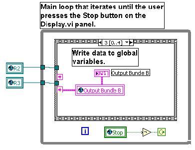
49 APPENDIX A DATA ACQUISITION AND CONTROL SOURCE CODE The DAQC software was written in the LabVIEW (version 5.1) graphical environment developed by National instruments. LabVIEW is based on the G programming language employing graphical representations of program elements such as arithmetic and Boolean operators, loops, data structures, etc. In LabVIEW, programs are called virtual instruments (VI s) and sub-programs are called sub-vi s. Each VI or sub- VI has a front panel for program input and output and a block diagram containing the source code. Presented below are both the front panels and block diagrams for the DAQC software written for this project. The six primary modules, Start-B.vi, Acquire B.vi, Process.vi, Display B.vi, Heater B.vi, and IMAQ.VI are given first. The sub-vi s called by these modules are then given in alphabetical order. Source code included with the LabVIEW package is not included. Also, empty Cases and Cases where the data is passed through unchanged are not included. The front panels and block diagrams are scaled to fit the page. The scaling is different for each VI shown. However, the scaling within each block diagram is the same. 38

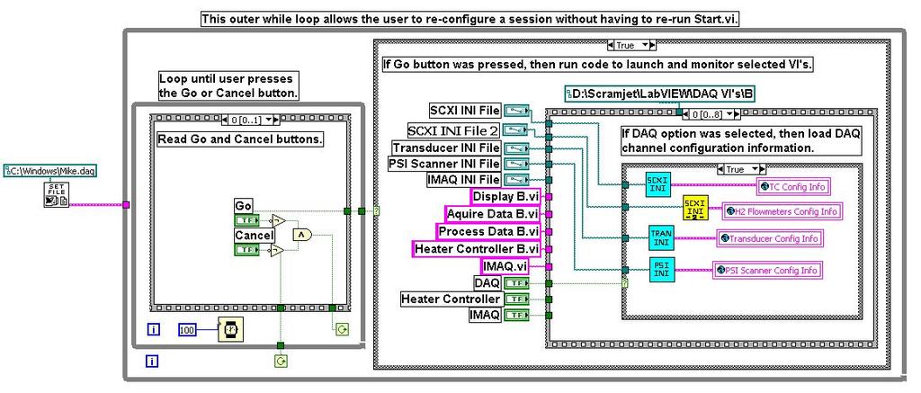
50 39 Block Diagram


51 40 Aquire Data B Block Diagram


52 41 Display B Block Diagram Heater Controller B


53 42 Block Diagram Process Data B


54 43 Block Diagram


55 44
Design Rules and Issues with Respect to Rocket Based Combined Cycles
 Respect to Rocket Based Combined Cycles Tetsuo HIRAIWA hiraiwa.tetsuo@jaxa.jp ABSTRACT JAXA Kakuda space center has been studying rocket based combined cycle engine for the future space transportation
Plasma Assisted Combustion in Complex Flow Environments
 High Fidelity Modeling and Simulation of Plasma Assisted Combustion in Complex Flow Environments Vigor Yang Daniel Guggenheim School of Aerospace Engineering Georgia Institute of Technology Atlanta, Georgia
Supersonic Combustion Experimental Investigation at T2 Hypersonic Shock Tunnel
 Supersonic Combustion Experimental Investigation at T2 Hypersonic Shock Tunnel D. Romanelli Pinto, T.V.C. Marcos, R.L.M. Alcaide, A.C. Oliveira, J.B. Chanes Jr., P.G.P. Toro, and M.A.S. Minucci 1 Introduction
Experimental Testing of a Rotating Detonation Engine Coupled to Nozzles at Conditions Approaching Flight
 25 th ICDERS August 2 7, 205 Leeds, UK Experimental Testing of a Rotating Detonation Engine Coupled to Nozzles at Conditions Approaching Flight Matthew L. Fotia*, Fred Schauer Air Force Research Laboratory
Scramjet Engine Research of KARI : Ground Tests of Engines and Components
 23 rd ICDERS July 24-29, 211 Irvine, USA Scramjet Engine Research of KARI : Ground Tests of Engines and Components Soo Seok Yang, Sang Hun Kang, Yang Ji Lee Aero Propulsion System Department, Korea Aerospace
In this lecture... Components of ramjets and pulsejets Ramjet combustors Types of pulsejets: valved and valveless, Pulse detonation engines
 In this lecture... Components of ramjets and pulsejets Ramjet combustors Types of pulsejets: valved and valveless, ulse detonation engines Ramjet engines Ramjet engines consist of intakes, combustors and
EXPERIMENTAL STUDIES OF INJECTOR ARRAY CONFIGURATIONS FOR CIRCULAR SCRAMJET COMBUSTORS
 EXPERIMENTAL STUDIES OF INJECTOR ARRAY CONFIGURATIONS FOR CIRCULAR SCRAMJET COMBUSTORS Christopher Rock Graduate Research Assistant and Joseph A. Schetz Advisor, Holder of the Fred D. Durham Chair Department
Experimental Research on Hydrogen and Hydrocarbon Fuel Ignition for Scramjet at Ma=4
 Modern Applied Science; Vol. 7, No. 3; 2013 ISSN 1913-1844 E-ISSN 1913-1852 Published by Canadian Center of Science and Education Experimental Research on Hydrogen and Hydrocarbon Fuel Ignition for Scramjet
Numerical simulation of detonation inception in Hydrogen / air mixtures
 Numerical simulation of detonation inception in Hydrogen / air mixtures Ionut PORUMBEL COMOTI Non CO2 Technology Workshop, Berlin, Germany, 08.03.2017 09.03.2017 Introduction Objective: Development of
Design Rules and Issues with Respect to Rocket Based Combined Cycles
 Respect to Rocket Based Combined Cycles Tetsuo HIRAIWA hiraiwa.tetsuo@jaxa.jp ABSTRACT JAXA Kakuda space center has been studying rocket based combined cycle engine for the future space transportation
Combustion characteristics of n-heptane droplets in a horizontal small quartz tube
 Combustion characteristics of n-heptane droplets in a horizontal small quartz tube Junwei Li*, Rong Yao, Zuozhen Qiu, Ningfei Wang School of Aerospace Engineering, Beijing Institute of Technology,Beijing
NON-PREMIXED CONDITIONS IN THE FLAMEHOLDING RECIRCULATION REGION BEHIND A STEP IN SUPERSONIC FLOW
 NON-PREMIXED CONDITIONS IN THE FLAMEHOLDING RECIRCULATION REGION BEHIND A STEP IN SUPERSONIC FLOW By AMIT THAKUR A DISSERTATION PRESENTED TO THE GRADUATE SCHOOL OF THE UNIVERSITY OF FLORIDA IN PARTIAL
Cross Flow Heat Exchanger H352
 Cross Flow Heat Exchanger H352 H352 Cross Flow Heat Exchanger Shown With Optional Plain Tube of H352A fitted. Allows Investigation Of Plain And Finned Cross Flow Heat Exchangers. Expandable Free & Forced
Stability Limits and Fuel Placement in Carbureted Fuel Injection System (CFIS) Flameholder. Phase I Final Report
 Flameholder. Phase I Final Report") Stability Limits and Fuel Placement in Carbureted Fuel Injection System (CFIS) Flameholder Phase I Final Report Reporting Period Start Date: 15 March 2007 Reporting Period End Date: 31 August 2007 PDPI:
Stability Limits and Fuel Placement in Carbureted Fuel Injection System (CFIS) Flameholder Phase I Final Report Reporting Period Start Date: 15 March 2007 Reporting Period End Date: 31 August 2007 PDPI:
HEAT TRANSFER MODES IN SUPERSONIC HYDROGEN COMBUSTION
 HEAT TRANSFER MODES IN SUPERSONIC HYDROGEN COMBUSTION Sara Esparza Benjamin Liu Cesar Olmedo Azizkhan Pathan Helen Boussalis, Ph.D. Center at Darrell Guillaume, Ph.D. Center at Chivey Wu, Ph.D. Center
Development of the Micro Combustor
 Development of the Micro Combustor TAKAHASHI Katsuyoshi : Advanced Technology Department, Research & Engineering Division, Aero-Engine & Space Operations KATO Soichiro : Doctor of Engineering, Heat & Fluid
Experimental Investigation of Hot Surface Ignition of Hydrocarbon-Air Mixtures
 Paper # 2D-09 7th US National Technical Meeting of the Combustion Institute Georgia Institute of Technology, Atlanta, GA Mar 20-23, 2011. Topic: Laminar Flames Experimental Investigation of Hot Surface
Supersonic Combustion of Liquid Hydrogen using Slotted Shaped Pylon Injectors
 Advances in Aerospace Science and Applications. ISSN 2277-3223 Volume 3, Number 3 (2013), pp. 131-136 Research India Publications http://www.ripublication.com/aasa.htm Supersonic Combustion of Liquid Hydrogen
Effects of Dilution Flow Balance and Double-wall Liner on NOx Emission in Aircraft Gas Turbine Engine Combustors
 Effects of Dilution Flow Balance and Double-wall Liner on NOx Emission in Aircraft Gas Turbine Engine Combustors 9 HIDEKI MORIAI *1 Environmental regulations on aircraft, including NOx emissions, have
Dean Andreadis Pratt & Whitney Space Propulsion, Hypersonics, West Palm Beach, FL,
 Dean Andreadis Pratt & Whitney Space Propulsion, Hypersonics, West Palm Beach, FL, 33410-9600 SCRAMJET ENGINES ENABLING THE SEAMLESS INTEGRATION OF AIR & SPACE OPERATIONS The desire to fly, to fly faster,
AE Aircraft Performance and Flight Mechanics
 AE 429 - Aircraft Performance and Flight Mechanics Propulsion Characteristics Types of Aircraft Propulsion Mechanics Reciprocating engine/propeller Turbojet Turbofan Turboprop Important Characteristics:
DESIGN AND TESTING OF A DUAL-MODE SCRAMJET FOR OPTICAL MEASUREMENT TECHNIQUES
 DESIGN AND TESTING OF A DUAL-MODE SCRAMJET FOR OPTICAL MEASUREMENT TECHNIQUES Author: Brian Advisor: Chris Goyne and Jim McDaniel University of Virginia Abstract The following research paper presents an
Analysis of Scramjet Engine With And Without Strut
 Analysis of Scramjet Engine With And Without Strut S. Ramkumar 1, M. S. Vijay Amal Raj 2, Rahul Mahendra Vaity 3 1.Assistant Professor NIT Coimbatore, 2. U.G.Student, NIT Coimbatore 3.U.G.Student MVJ College
Effects of Spent Cooling and Swirler Angle on a 9-Point Swirl-Venturi Low-NOx Combustion Concept
 Paper # 070IC-0023 Topic: Internal combustion and gas turbine engines 8 th U. S. National Combustion Meeting Organized by the Western States Section of the Combustion Institute and hosted by the University
Fuel Injection and Combustion Study for Mach Scramjet. Dora E. Musielak University of Texas at Arlington
 Fuel Injection and Combustion Study for Mach 10-12 Scramjet Dora E. Musielak University of Texas at Arlington dmusielak@uta.edu ABSTRACT A research program to support the development of scramjet engine
University Turbine Systems Research Industrial Fellowship. Southwest Research Institute
 Correlating Induced Flashback with Air- Fuel Mixing Profiles for SoLoNOx Biomass Injector Ryan Ehlig University of California, Irvine Mentor: Raj Patel Supervisor: Ram Srinivasan Department Manager: Andy
Dual-Mode Combustion of a Jet in Cross-Flow with Cavity Flameholder
 46th AIAA Aerospace Sciences Meeting and Exhibit 7-1 January 28, Reno, Nevada AIAA 28-162 Dual-Mode Combustion of a Jet in Cross-Flow with Cavity Flameholder Daniel J. Micka, James F. Driscoll University
ia 451s, 10-y (12) Patent Application Publication (10) Pub. No.: US 2003/ A1 (19) United States Johnson et al. (43) Pub. Date: Feb.
 Patent Application Publication (10) Pub. No.: US 2003/ A1 (19) United States Johnson et al. (43) Pub. Date: Feb.") (19) United States US 2003OO29160A1 (12) Patent Application Publication (10) Pub. No.: US 2003/0029160 A1 Johnson et al. (43) Pub. Date: Feb. 13, 2003 (54) COMBINED CYCLE PULSE DETONATION TURBINE ENGINE
(19) United States US 2003OO29160A1 (12) Patent Application Publication (10) Pub. No.: US 2003/0029160 A1 Johnson et al. (43) Pub. Date: Feb. 13, 2003 (54) COMBINED CYCLE PULSE DETONATION TURBINE ENGINE
IAC-15-C4.3.1 JET INDUCER FOR A TURBO PUMP OF A LIQUID ROCKET ENGINE
 IAC-15-C4.3.1 JET INDUCER FOR A TURBO PUMP OF A LIQUID ROCKET ENGINE Martin Böhle Technical University Kaiserslautern, Germany, martin.boehle@mv.uni-kl.de Wolfgang Kitsche German Aerospace Center (DLR),
CFD Analysis on a Different Advanced Rocket Nozzles
 International Journal of Engineering and Advanced Technology (IJEAT) CFD Analysis on a Different Advanced Rocket Nozzles Munipally Prathibha, M. Satyanarayana Gupta, Simhachalam Naidu Abstract The reduction
Metrovick F2/4 Beryl. Turbo-Union RB199
 Turbo-Union RB199 Metrovick F2/4 Beryl Development of the F2, the first British axial flow turbo-jet, began in f 940. After initial flight trials in the tail of an Avro Lancaster, two F2s were installed
Design Fabrication And Performance Analysis Of Subsonic RAMJET Engine
 Design Fabrication And Performance Analysis Of Subsonic RAMJET Engine Dr.J.V.Sai Prasanna Kumar[1], Revathi.K, Sabarigirinathan.R, Santhosh Kumar.M, UdhayaKumar.T, Viswanath.S [2] Head of the Department,
TURBOPROP ENGINE App. K AIAA AIRCRAFT ENGINE DESIGN
 CORSO DI LAUREA SPECIALISTICA IN Ingegneria Aerospaziale PROPULSIONE AEROSPAZIALE I TURBOPROP ENGINE App. K AIAA AIRCRAFT ENGINE DESIGN www.amazon.com LA DISPENSA E E DISPONIBILE SU http://www.ingindustriale.unisalento.it/didattica/
Experiments in a Combustion-Driven Shock Tube with an Area Change
 Accepted for presentation at the 29th International Symposium on Shock Waves. Madison, WI. July 14-19, 2013. Paper #0044 Experiments in a Combustion-Driven Shock Tube with an Area Change B. E. Schmidt
Cross Flow Heat Exchanger H352
 Cross Flow Heat Exchanger H352 H352 Shown With Optional Plain Tube of H352A fitted. Allows Investigation Of Plain And Finned Cross Flow Heat Exchangers. Expandable Free & Forced Convection Heat Transfer
Multipulse Detonation Initiation by Spark Plugs and Flame Jets
 Multipulse Detonation Initiation by Spark Plugs and Flame Jets S. M. Frolov, V. S. Aksenov N.N. Semenov Institute of Chemical Physics, Russian Academy of Sciences, Moscow, Russia Moscow Physical Engineering
SWIRL MEASURING EQUIPMENT FOR DIRECT INJECTION DIESEL ENGINE
 SWIRL MEASURING EQUIPMENT FOR DIRECT INJECTION DIESEL ENGINE G.S.Gosavi 1, R.B.Solankar 2, A.R.Kori 3, R.B.Chavan 4, S.P.Shinde 5 1,2,3,4,5 Mechanical Engineering Department, Shivaji University, (India)
Engine Performance Analysis
 Engine Performance Analysis Introduction The basics of engine performance analysis The parameters and tools used in engine performance analysis Introduction Parametric cycle analysis: Independently selected
FLUIDIC THRUST VECTORING NOZZLES
 FLUIDIC THRUST VECTORING NOZZLES J.J. Isaac and C. Rajashekar Propulsion Division National Aerospace Laboratories (Council of Scientific & Industrial Research) Bangalore 560017, India April 2014 SUMMARY
Module7:Advanced Combustion Systems and Alternative Powerplants Lecture 32:Stratified Charge Engines
 ADVANCED COMBUSTION SYSTEMS AND ALTERNATIVE POWERPLANTS The Lecture Contains: DIRECT INJECTION STRATIFIED CHARGE (DISC) ENGINES Historical Overview Potential Advantages of DISC Engines DISC Engine Combustion
Chapter 4 Lecture 16. Engine characteristics 4. Topics. Chapter IV
 Chapter 4 Lecture 16 Engine characteristics 4 Topics 4.3.3 Characteristics of a typical turboprop engine 4.3.4 Characteristics of a typical turbofan engine 4.3.5 Characteristics of a typical turbojet engines
Investigation of converging slot-hole geometry for film cooling of gas turbine blades
 Project Report 2010 MVK160 Heat and Mass Transport May 12, 2010, Lund, Sweden Investigation of converging slot-hole geometry for film cooling of gas turbine blades Tobias Pihlstrand Dept. of Energy Sciences,
Study on Flow Fields in Variable Area Nozzles for Radial Turbines
 Vol. 4 No. 2 August 27 Study on Fields in Variable Area Nozzles for Radial Turbines TAMAKI Hideaki : Doctor of Engineering, P. E. Jp, Manager, Turbo Machinery Department, Product Development Center, Corporate
Observation of Flame Stabilized at a Hydrogen-Turbojet-Engine Injector Installed into a Lab-Scale Combustion Wind Tunnel
 Trans. JSASS Aerospace Tech. Japan Vol. 1, No. ists28, pp. Pa_19-Pa_24, 212 Original Paper Observation of Flame Stabilized at a Hydrogen-Turbojet-Engine Injector Installed into a Lab-Scale Combustion Wind
Numerical Simulation of Gas Turbine Can Combustor Engine
 Numerical Simulation of Gas Turbine Can Combustor Engine CH UMAMAHESHWAR PRAVEEN 1*, A HEMANTH KUMAR YADAV 2 1. Engineer, CDG BOEING Company, Chennai, India. 2. B.Tech Aeronautical Engineer 2012 passout,
2) Rich mixture: A mixture which contains less air than the stoichiometric requirement is called a rich mixture (ex. A/F ratio: 12:1, 10:1 etc.
 Rich mixture: A mixture which contains less air than the stoichiometric requirement is called a rich mixture (ex. A/F ratio: 12:1, 10:1 etc.") Unit 3. Carburettor University Questions: 1. Describe with suitable sketches : Main metering system and Idling system 2. Draw the neat sketch of a simple carburettor and explain its working. What are the
Unit 3. Carburettor University Questions: 1. Describe with suitable sketches : Main metering system and Idling system 2. Draw the neat sketch of a simple carburettor and explain its working. What are the
Normal vs Abnormal Combustion in SI engine. SI Combustion. Turbulent Combustion
 Turbulent Combustion The motion of the charge in the engine cylinder is always turbulent, when it is reached by the flame front. The charge motion is usually composed by large vortexes, whose length scales
Applied Fluid Mechanics
 Applied Fluid Mechanics 1. The Nature of Fluid and the Study of Fluid Mechanics 2. Viscosity of Fluid 3. Pressure Measurement 4. Forces Due to Static Fluid 5. Buoyancy and Stability 6. Flow of Fluid and
Supersonic Combustion Flow Visualization at Hypersonic Flow
 Supersonic Combustion Flow Visualization at Hypersonic Flow T.V.C. Marcos, D. Romanelli Pinto, G.S. Moura, A.C. Oliveira, J.B. Chanes Jr., P.G.P. Toro, and M.A.S. Minucci 1 Introduction Currently, a new
Numerical Simulation of Cavity Fuel Injection and Combustion for Mach Scramjet. Dora E. Musielak University of Texas at Arlington
 Numerical Simulation of Cavity Fuel Injection and Combustion for Mach 10-12 Scramjet Dora E. Musielak University of Texas at Arlington ABSTRACT We report the results from a study of cavity flame holding
Lecture 27: Principles of Burner Design
 Lecture 27: Principles of Burner Design Contents: How does combustion occur? What is a burner? Mixing of air and gaseous fuel Characteristic features of jet Behavior of free (unconfined) and confined jet
Modern Approach to Liquid Rocket Engine Development for Microsatellite Launchers
 Modern Approach to Liquid Rocket Engine Development for Microsatellite Launchers SoftInWay: Turbomachinery Mastered 2018 SoftInWay, Inc. All Rights Reserved. Introduction SoftInWay: Turbomachinery Mastered
PROVISIONAL PATENT APPLICATION INVENTORS: RICHARD E. AHO CAVITATION ENGINE
 PROVISIONAL PATENT APPLICATION INVENTORS: RICHARD E. AHO WILLIAM WALTER MEE FOR CAVITATION ENGINE Richard E. Aho 4170 N.W.42 St. Lauderdale Lakes, FL 33319 William Walter Mee 8591 Pioneer Road West Palm
A Study of EGR Stratification in an Engine Cylinder
 A Study of EGR Stratification in an Engine Cylinder Bassem Ramadan Kettering University ABSTRACT One strategy to decrease the amount of oxides of nitrogen formed and emitted from certain combustion devices,
AERODYNAMIC PERFORMANCES OF THE COMBINED CYCLE INLET
 24 TH INTERNATIONAL CONGRESS OF THE AERONAUTICAL SCIENCES AERODYNAMIC PERFORMANCES OF THE COMBINED CYCLE INLET Shinji Kubota* Kouichirou Tani**, Goro Masuya* *Tohoku University, **Japan Aerospace Exploration
Module 3: Influence of Engine Design and Operating Parameters on Emissions Lecture 14:Effect of SI Engine Design and Operating Variables on Emissions
 Module 3: Influence of Engine Design and Operating Parameters on Emissions Effect of SI Engine Design and Operating Variables on Emissions The Lecture Contains: SI Engine Variables and Emissions Compression
1. Aero-Science B.Sc. Aero Science-I Total Mark: 100 Appendix A (Outlines of Tests) Aero-Engines : 100 Marks
 Aero-Engines : 100 Marks") 1. Aero-Science B.Sc. Aero Science-I Total Mark: 100 Appendix A (Outlines of Tests) Aero-Engines : 100 Marks Note:- The questions will be set in each paper. Candidates are to attempt any five except in
1. Aero-Science B.Sc. Aero Science-I Total Mark: 100 Appendix A (Outlines of Tests) Aero-Engines : 100 Marks Note:- The questions will be set in each paper. Candidates are to attempt any five except in
HIGH VELOCITY THERMAL GUN FOR SURFACE PREPARATION AND TREATMENT. I.A. Gorlach
 HIGH VELOCITY THERMAL GUN FOR SURFACE PREPARATION AND TREATMENT I.A. Gorlach Department of Industrial Engineering School of Process and Mechanical Engineering Technikon Witwatersrand Johannesburg, South
Chapter 9 GAS POWER CYCLES
 Thermodynamics: An Engineering Approach, 6 th Edition Yunus A. Cengel, Michael A. Boles McGraw-Hill, 2008 Chapter 9 GAS POWER CYCLES Copyright The McGraw-Hill Companies, Inc. Permission required for reproduction
Aircraft Propulsion Technology
 Unit 90: Aircraft Propulsion Technology Unit code: L/601/7249 QCF level: 4 Credit value: 15 Aim This unit aims to develop learners understanding of the principles and laws of aircraft propulsion and their
Rotary Internal Combustion Engine: Inventor: Gary Allen Schwartz
 Rotary Internal Combustion Engine: Inventor: Gary Allen Schwartz 1 The following is a design for a circular engine that can run on multiple fuels. It is much more efficient than traditional reciprocating
IAC-04-IAF-S.2.06 NEW PROPELLANT IGNITION SYSTEM IN LV SOYUZ ROCKET ENGINE CHAMBERS
 IAC-04-IAF-S.2.06 NEW PROPELLANT IGNITION SYSTEM IN LV SOYUZ ROCKET ENGINE CHAMBERS Igor Yu. Fatuev, Anatoly A.Ganin NPO Energomash named after academician V.P.Glushko, Russia, 141400, Khimky, Moscow area,
FLAME COOLING AND RESIDENCE TIME EFFECT ON NO x AND CO EMISSION IN A GAS TURBINE COMBUSTOR
 FLAME COOLING AND RESIDENCE TIME EFFECT ON NO x AND CO EMISSION IN A GAS TURBINE COMBUSTOR MOHAMED S. T. ZAWIA Engineering College Tajoura Mech. Eng. Dept. El-Fateh University P.O Box 30797 Libya E-mail
Fig 2: Grid arrangements for axis-symmetric Rocket nozzle.
 CFD Analysis of Rocket-Ramjet Combustion Chamber 1 Ms. P.Premalatha, Asst. Prof., PSN College of Engineering and Technology, Tirunelveli. 1prema31194@gmail.com 1 +91-90475 26413 2 Ms. T. Esakkiammal, Student,
Heat Transfer Enhancement for Double Pipe Heat Exchanger Using Twisted Wire Brush Inserts
 Heat Transfer Enhancement for Double Pipe Heat Exchanger Using Twisted Wire Brush Inserts Deepali Gaikwad 1, Kundlik Mali 2 Assistant Professor, Department of Mechanical Engineering, Sinhgad College of
ME3264: LAB 9 Gas Turbine Power System
 OBJECTIVE ME3264: LAB 9 Gas Turbine Power System Professor Chih-Jen Sung Spring 2013 A fully integrated jet propulsion system will be used for the study of thermodynamic and operating principles of gas
Smoke Reduction Methods Using Shallow-Dish Combustion Chamber in an HSDI Common-Rail Diesel Engine
 Special Issue Challenges in Realizing Clean High-Performance Diesel Engines 17 Research Report Smoke Reduction Methods Using Shallow-Dish Combustion Chamber in an HSDI Common-Rail Diesel Engine Yoshihiro
Rotating Detonation Wave Stability. Piotr Wolański Warsaw University of Technology
 Rotating Detonation Wave Stability Piotr Wolański Warsaw University of Technology Abstract In this paper the analysis of stability of rotating detonation wave in cylindrical channel is discussed. On the
PERFORMANCE ESTIMATION AND ANALYSIS OF PULSE DETONATION ENGINE WITH DIFFERENT BLOCKAGE RATIOS FOR HYDROGEN-AIR MIXTURE
 PERFORMANCE ESTIMATION AND ANALYSIS OF PULSE DETONATION ENGINE WITH DIFFERENT BLOCKAGE RATIOS FOR HYDROGEN-AIR MIXTURE Nadella Karthik 1, Repaka Ramesh 2, N.V.V.K Chaitanya 3, Linsu Sebastian 4 1,2,3,4
In this lecture... Fixed and variable geometry nozzles Functions of nozzles Thrust vector control Thrust reversal Noise control
 1 In this lecture... Nozzle: Fixed and variable geometry nozzles Functions of nozzles Thrust vector control Thrust reversal Noise control 2 Exhaust nozzles Nozzles form the exhaust system of gas turbine
in ultra-low NOx lean combustion grid plate
 CFD predictions of aerodynamics and mixing in ultra-low NOx lean combustion grid plate flame stabilizer JOSÉ RAMÓN QUIÑONEZ ARCE, DR. ALAN BURNS, PROF. GORDON E. ANDREW S. SCHOOL OF CHEMICAL AND PROCESS
AE 452 Aeronautical Engineering Design II Installed Engine Performance. Prof. Dr. Serkan Özgen Dept. Aerospace Engineering March 2016
 AE 452 Aeronautical Engineering Design II Installed Engine Performance Prof. Dr. Serkan Özgen Dept. Aerospace Engineering March 2016 Propulsion 2 Propulsion F = ma = m V = ρv o S V V o ; thrust, P t =
Permanent Multipath Clamp-On Transit Time Flow Meter
 Permanent Multipath Clamp-On Transit Time Flow Meter By: Dr. J. Skripalle HydroVision GmbH, Germany Introduction For many years now, ultrasonic flow measurements with wetted sensors have been a well established
STUDY ON COMPACT HEAT EXCHANGER FOR VEHICULAR GAS TURBINE ENGINE
 Proceedings of Fifth International Conference on Enhanced, Compact and Ultra-Compact Heat Exchangers: Science, Engineering and Technology, Eds. R.K. Shah, M. Ishizuka, T.M. Rudy, and V.V. Wadekar, Engineering
1.1 The Ramjet and the Supersonic Combustion Ramjet (Scramjet) Engine Cycle
 Engine Cycle") 1 Introduction 1.1 The Ramjet and the Supersonic Combustion Ramjet (Scramjet) Engine Cycle An invention attributed to René Lorin of France in 1913 (Hallion, 1995), the ramjet is a remarkable air-breathing
1 Introduction 1.1 The Ramjet and the Supersonic Combustion Ramjet (Scramjet) Engine Cycle An invention attributed to René Lorin of France in 1913 (Hallion, 1995), the ramjet is a remarkable air-breathing
Welcome to Aerospace Engineering
 Welcome to Aerospace Engineering DESIGN-CENTERED INTRODUCTION TO AEROSPACE ENGINEERING Notes 5 Topics 1. Course Organization 2. Today's Dreams in Various Speed Ranges 3. Designing a Flight Vehicle: Route
THE RIG STAND FOR TESTING INTEGRATED ROCKET RAMJET ENGINE
 Journal of KONES Powertrain and Transport, Vol. 23, No. 4 2016 THE RIG STAND FOR TESTING INTEGRATED ROCKET RAMJET ENGINE Artur Rowiński Institute of Aviation Krakowska Avenue 110/114, 02-256 Warsaw, Poland
ACTUAL CYCLE. Actual engine cycle
 1 ACTUAL CYCLE Actual engine cycle Introduction 2 Ideal Gas Cycle (Air Standard Cycle) Idealized processes Idealize working Fluid Fuel-Air Cycle Idealized Processes Accurate Working Fluid Model Actual
Combustion Equipment. Combustion equipment for. Solid fuels Liquid fuels Gaseous fuels
 Combustion Equipment Combustion equipment for Solid fuels Liquid fuels Gaseous fuels Combustion equipment Each fuel type has relative advantages and disadvantages. The same is true with regard to firing
Reentry Demonstration Plan of Flare-type Membrane Aeroshell for Atmospheric Entry Vehicle using a Sounding Rocket
 AIAA ADS Conference 2011 in Dublin 1 Reentry Demonstration Plan of Flare-type Membrane Aeroshell for Atmospheric Entry Vehicle using a Sounding Rocket Kazuhiko Yamada, Takashi Abe (JAXA/ISAS) Kojiro Suzuki
Chapter 9 GAS POWER CYCLES
 Thermodynamics: An Engineering Approach Seventh Edition in SI Units Yunus A. Cengel, Michael A. Boles McGraw-Hill, 2011 Chapter 9 GAS POWER CYCLES Mehmet Kanoglu University of Gaziantep Copyright The McGraw-Hill
COMPUTATIONAL ANALYSIS DIAMOND-SHAPED STRUT INJECTOR FOR SCRAMJET COMBUSTOR AT MACH 4.3 S. Roga1,K.M. Pandey2 and A.P.Singh3 1
 ISSN: 2395-3594 IJAET International Journal of Application of Engineering and Technology Vol-2 No.-2 COMPUTATIONAL ANALYSIS DIAMOND-SHAPED STRUT INJECTOR FOR SCRAMJET COMBUSTOR AT MACH 4.3 S. Roga1,K.M.
METHANE/OXYGEN LASER IGNITION IN AN EXPERIMENTAL ROCKET COMBUSTION CHAMBER: IMPACT OF MIXING AND IGNITION POSITION
 SP2016_3124927 METHANE/OXYGEN LASER IGNITION IN AN EXPERIMENTAL ROCKET COMBUSTION CHAMBER: IMPACT OF MIXING AND IGNITION POSITION Michael Wohlhüter, Victor P. Zhukov, Michael Börner Institute of Space
Numerical Analysis of External Supersonic Combustion of Hydrogen and Ethylene
 16 th Australasian Fluid Mechanics Conference Crown Plaza, Gold Coast, Australia 2-7 December 2007 Numerical Analysis of External Supersonic Combustion of Hydrogen and Ethylene J. R. Jones and F. C. Christo
CFD ANALYSIS ON LOUVERED FIN
 CFD ANALYSIS ON LOUVERED FIN P.Prasad 1, L.S.V Prasad 2 1Student, M. Tech Thermal Engineering, Andhra University, Visakhapatnam, India 2Professor, Dept. of Mechanical Engineering, Andhra University, Visakhapatnam,
Development of a Non-Catalytic JP-8 Reformer
 2018 NDIA GROUND VEHICLE SYSTEMS ENGINEERING AND TECHNOLOGY SYMPOSIUM POWER & MOBILITY (P&M) TECHNICAL SESSION AUGUST 7-9, 2018 - NOVI, MICHIGAN Development of a Non-Catalytic JP-8 Reformer Chien-Hua Chen,
LD24 SOLID FUEL RAMJET (SFRJ) PROPULSION FOR ARTILLERY PROJECTILE APPLICATIONS CONCEPT DEVELOPMENT OVERVIEW
 PROPULSION FOR ARTILLERY PROJECTILE APPLICATIONS CONCEPT DEVELOPMENT OVERVIEW") LD24 19th International Symposium of Ballistics, 7 11 May 2001, Interlaken, Switzerland SOLID FUEL RAMJET (SFRJ) PROPULSION FOR ARTILLERY PROJECTILE APPLICATIONS CONCEPT DEVELOPMENT OVERVIEW R. Oosthuizen1,
LD24 19th International Symposium of Ballistics, 7 11 May 2001, Interlaken, Switzerland SOLID FUEL RAMJET (SFRJ) PROPULSION FOR ARTILLERY PROJECTILE APPLICATIONS CONCEPT DEVELOPMENT OVERVIEW R. Oosthuizen1,
EFFECT OF INJECTION ORIENTATION ON EXHAUST EMISSIONS IN A DI DIESEL ENGINE: THROUGH CFD SIMULATION
 EFFECT OF INJECTION ORIENTATION ON EXHAUST EMISSIONS IN A DI DIESEL ENGINE: THROUGH CFD SIMULATION *P. Manoj Kumar 1, V. Pandurangadu 2, V.V. Pratibha Bharathi 3 and V.V. Naga Deepthi 4 1 Department of
Development and Implementation of Interactive/Visual Software for Simple Aircraft Gas Turbine Design
 Development and Implementation of Interactive/Visual Software for Simple Aircraft Gas Turbine Design Afshin J. Ghajar, Ronald D. Delahoussaye, Vandan V. Nayak School of Mechanical and Aerospace Engineering,
Marc ZELLAT, Driss ABOURI, Thierry CONTE and Riyad HECHAICHI CD-adapco
 16 th International Multidimensional Engine User s Meeting at the SAE Congress 2006,April,06,2006 Detroit, MI RECENT ADVANCES IN SI ENGINE MODELING: A NEW MODEL FOR SPARK AND KNOCK USING A DETAILED CHEMISTRY
CONTENTS Duct Jet Propulsion / Rocket Propulsion / Applications of Rocket Propulsion / 15 References / 25
 CONTENTS PREFACE xi 1 Classification 1.1. Duct Jet Propulsion / 2 1.2. Rocket Propulsion / 4 1.3. Applications of Rocket Propulsion / 15 References / 25 2 Definitions and Fundamentals 2.1. Definition /
Component and System Level Modeling of a Two-Phase Cryogenic Propulsion System for Aerospace Applications
 Component and System Level Modeling of a Two-Phase Cryogenic Propulsion System for Aerospace Applications J. LoRusso, B. Kalina, M. Van Benschoten, Roush Industries GT Users Conference November 9, 2015
Introduction to Gas Turbine Engines
 Introduction to Gas Turbine Engines Introduction Gas Turbine Engine - Configurations Gas Turbine Engine Gas Generator Compressor is driven by the turbine through an interconnecting shaft Turbine is driven
Experiment (4): Flow measurement
: Flow measurement") Introduction: The flow measuring apparatus is used to familiarize the students with typical methods of flow measurement of an incompressible fluid and, at the same time demonstrate applications of the
Introduction: The flow measuring apparatus is used to familiarize the students with typical methods of flow measurement of an incompressible fluid and, at the same time demonstrate applications of the
ENGINE STARTING PERFORMANCE EVALUATION AT STATIC STATE CONDITIONS USING SUPERSONIC AIR INTAKE
 24 TH INTERNATIONAL CONGRESS OF THE AERONAUTICAL SCIENCES STARTING PERFORMANCE EVALUATION AT STATIC STATE CONDITIONS USING SUPERSONIC AIR INTAKE Author1* Takashi Nishikido Author2* Iwao Murata Author3**
Chapter 4 Estimation of wing loading and thrust loading - 10 Lecture 18 Topics
 Chapter 4 Estimation of wing loading and thrust loading - 10 Lecture 18 Topics 4.15.3 Characteristics of a typical turboprop engine 4.15.4 Characteristics of a typical turbofan engine 4.15.5 Characteristics
State Legislation, Regulation or Document Reference. Civil Aviation Rule (CAR) ; Civil Aviation Rules (CAR) Part 21. Appendix C.
 ; Civil Aviation Rules (CAR) Part 21. Appendix C.") Annex or Recommended Practice Definition INTERNATIONAL STANDARDS AND RECOMMENDED PRACTICES PART I. DEFINITIONS AND SYMBOLS Civil Aviation Rule (CAR) 91.807; Civil Aviation Rules (CAR) Part 21 The s of
Annex or Recommended Practice Definition INTERNATIONAL STANDARDS AND RECOMMENDED PRACTICES PART I. DEFINITIONS AND SYMBOLS Civil Aviation Rule (CAR) 91.807; Civil Aviation Rules (CAR) Part 21 The s of
Module 2:Genesis and Mechanism of Formation of Engine Emissions Lecture 3: Introduction to Pollutant Formation POLLUTANT FORMATION
 Module 2:Genesis and Mechanism of Formation of Engine Emissions POLLUTANT FORMATION The Lecture Contains: Engine Emissions Typical Exhaust Emission Concentrations Emission Formation in SI Engines Emission
EXPERIMENTAL INVESTIGATION OF THE FLOWFIELD OF DUCT FLOW WITH AN INCLINED JET INJECTION DIFFERENCE BETWEEN FLOWFIELDS WITH AND WITHOUT A GUIDE VANE
 Proceedings of the 3rd ASME/JSME Joint Fluids Engineering Conference July 8-23, 999, San Francisco, California FEDSM99-694 EXPERIMENTAL INVESTIGATION OF THE FLOWFIELD OF DUCT FLOW WITH AN INCLINED JET
Numerical Simulation on the Pattern Factor of the Annular Combustor
 Numerical Simulation on the Pattern Factor of the Annular Combustor Balakrishnan B.M 1, Mohana Priya G 2, Revathi M 3 Department of Mechanical Engineering, Mahendra Engineering College, Salem, India 1