Measurement Products. Level measurement Proven level technologies providing reliable measurement solutions for process and utility applications
|
|
|
- Jody Henderson
- 5 years ago
- Views:
Transcription

1 Measurement Products Level measurement Proven level technologies providing reliable measurement solutions for process and utility applications


2 Expertise in technology More than a century of experience To operate any process efficiently, it is essential to measure, actuate, record and control. In selecting ABB you are choosing a partner who is offering the best measurement solution for your needs, enabling maximum return on your investment. When investing in ABB s measurement products and solutions you are receiving the best technology, reliability and service in the business. Research and development is a vital source of ABB s technology leadership. ABB constantly builds on the foundation of existing technologies for new applications, and continues to develop the breakthrough technologies needed to meet the challenges of the future. ABB and its heritage companies have been leaders in innovation and technology for more than 100 years. We are proud to include the K-TEK level product line in the ABB family of measurement solutions. Aztec Pressductor 2 Level measurement solutions


3 Comprehensive measurement solutions Serving any industry ABB measurement products provide world-class measurement solutions for any industry, utility or municipality. Latest innovations deliver technological solutions to make it easier for you to run your plant. ABB s measurement products are based on common technology, providing a common look and feel and method of operation. This results in products that are easy to configure, easy to integrate, and easy to maintain. ABB s measurement products portfolio: Analytical measurements Flow measurement Natural gas measurement Valve automation Pressure measurement Temperature measurement Recorders and controllers Level measurement Device management Force measurement Service 1 Water and waste water 2 Power and industrial steam 3 Chemical and petrochemical 4 Oil and gas 5 Pulp and paper 6 Minerals 7 Metals 8 Food and beverage 9 Pharmaceuticals Level measurement solutions 3

4 ABB offers the most complete level measurement product line in the world 4 Level measurement solutions

5 Level measurement is a critical process parameter used in a variety of commercial and industrial applications around the world. ABB has the proven technology to provide solutions for the most difficult level applications for both liquids and solids. From tall grain silos to high pressure boilers and process vessels, ABB offers a wide breadth of level technologies, certifications and approvals to meet the needs of the most demanding applications. With the recent acquisition of K-TEK, a market leader in level detection, and ABB s existing hydrostatic level product lines, ABB now offers the most complete level measurement product line in the world. ABB provides reliable level solutions no matter how difficult the application may be. Precision engineered instruments built to specific customer requirements SIL2/3 certified transmitters Products that are easy to commission and calibrate, saving time and expense during a startup Largest selection of agency approved level switch technologies in the market Measurement solutions for both liquid and solids level applications Whether an application requires a cutting-edge solution, such as the non-contact laser or ultrasonic level transmitter, or ultra high pressure magnetic level gauges, transmitters and switches, ABB has the right technology for liquid or solids level detection needs. Level measurement solutions 5


6 Measure two fluids in the same vessel? Absolutely. On and offshore oil and gas production facilities have some of the most challenging level measurement applications in the exploration industry. High pressure separators, for example, contain two separate fluids in the same vessel as when oil floats on top of water. Both fluid levels need to be measured on a continuous basis without disrupting the operation of the oil and gas processing plant. To accurately accomplish this, a technology with interface capabilities is required. The ABB solution The KM26 magnetic level gauge and AT200 magnetostrictive level transmitter utilize precision engineered floats that are specifically designed to float with half their volume in the upper fluid and half in the lower fluid. When accurate specifications of the fluids are provided, interface density differences as low as 0.04 specific gravity can be accurately measured. Since the vessel contents are totally contained within the float chamber, the same magnetic level float can be used to actuate limit switches or continuous level transmitting devices without disturbing existing piping or vessels. Installation and modification can be administered while the platform is on-line. This allows for easy integration of leveling technology into the distributed control systems (DCS). Other suitable technologies for the oil and gas industry MT series guided wave radar level transmitters MW05 MagWave level system AT series magnetostrictive level transmitters Vibrating fork level switches Gauge and differential pressure level transmitters LM7100 LevelMaster liquid level sensor KM26 magnetic level gauge installed on a separator 6 Level measurement solutions


7 Smart level gauge beyond the sight glass In today s global chemical industry, process optimization and waste reduction is crucial. Continuous and point level measurement instrumentation provide the accuracy and reliability needed by chemical manufacturers worldwide. From radar and magnetostrictive, to non-contact ultrasonic and laser technologies, ABB has the solution for the toughest level application. The ABB solution The KM26 magnetic level gauge provides safe, reliable liquid level measurement with the added ability of optional transmitters and switches to make the KM26 a truly smart level gauge. With limited leak paths, no glass in contact with the process and ultra high pressure and temperature ratings, the magnetic level gauge addresses many of the traditional challenges faced by older technology sight glass gauges. ASME code manufacturing standards ensure long lasting performance with little or no maintenance. Other suitable technologies for the chemical industry MT series guided wave radar level transmitters AT series magnetostrictive level transmitters RS80 vibrating fork level switch Gauge and differential pressure level transmitters KM26/AT200 installed on a chemical storage tank Level measurement solutions 7

8 A new level of safety for the refining industry In the hazardous refining industry environment, plant operators require reliable level measurement solutions to manage high pressure and temperature applications. Because of the inherent danger found in refineries, critical issues of overflow prevention and maintaining level measurement accuracy is crucial. Instrumentation designed for Safety Instrumented Systems (SIS) are ideal to maintain the margin of safety and reliability required. Only ABB offers certified guided wave radar and magnetostrictive level transmitters to the exacting IEC safety standard. The ABB solution The ABB MT series of guided wave radars and AT series of magnetostrictive transmitters are the only level transmitters in the world to be IEC certified for operation in SIL2 (Safety Integrity Level 2) environments and are SIL3 approved with redundancy. The guided wave radar s self-monitoring capability continually checks for any faults that could cause device failures or false indications, and the magnetostrictive transmitter s strong electrical return pulse provides highly reliable measurements. These two technologies offer the best in safety and reliable communication, even in the harshest environments. Other suitable technologies for the refining industry KM26 magnetic level gauge RS80 vibrating fork level switches TX thermal dispersion level/flow switches Gauge and differential pressure level transmitters The only level transmitters to receive IEC certification for operation in SIL2 environments 8 Level measurement solutions


9 The power to improve plant efficiency The ability to produce safe, efficient power is essential to a modern society. ABB offers advanced level measurement technologies for both liquids and solids that accurately and consistently provide process level measurement and control in power plant environments. In an effort to improve plant heatrate and overall system efficiencies, power generating facilities around the globe are rapidly upgrading antiquated level instruments with ABB technology. Power plants often have high pressure and temperature applications where accuracy is critical. The ABB solution The K-TEK MagWave dual chamber redundant level system has a proven record of improving feedwater heater reliablity in power plants around the world. The MagWave combines a highly visible magnetic level indicator with the precise level measurement of a guided wave radar transmitter. Featuring a single probe transmitter in a standard 1.5 inch secondary chamber, the MagWave provides the measurement capabilities of a coaxial probe without the potential for fouling. Redundant level control can be achieved by adding a magnetostrictive transmitter or switch to the float chamber. Other suitable technologies for the power industry KM26 magnetic level gauge AT series magnetostrictive level transmitters MT series guided wave radar level transmitters Gauge and differential pressure level transmitters MW05 MagWave level system installed at a solar power plant Level measurement solutions 9


10 A level solution for open channel flow measurement Reliable water level measurement in the treatment unit of any industrial plant or utilities can present challenges to level measurement instrumentation. Often the chemical and physical properties of the processed water can change drastically with composition from different acids, flocculants, surfactants or other water treatment processes. These constant changes in water makeup prevent many traditional level technologies from working accurately. Also, traditional contact level methods often mandate the usage of special metals or coatings. Customer preferences are shifting to noncontact level measurement. With global privatization of the water industry, highly accurate measurements and solutions will continue to be required. The ABB solution ABB s non-contact ultrasonic level transmitters and transducers provide the accuracy needed for surface foam conditions of many water and wastewater industry applications. Along with traditional level measurement, ultrasonic technology has sophisticated electronics and software that allow for flow measurement of flumes or weirs. Other suitable technologies for the water and wastewater industries LM80 laser level transmitter KCAP series RF capacitance switches SP60 vibrating fork level switch K10C ultrasonic transducer installed at a wastewater facility. 10 Level measurement solutions


11 Pioneering new process controls for sustainability Safety and process control are among the primary concerns when working in a mining environment. The variety of different level applications in mining requires unique, proven technologies. ABB offers a comprehensive selection of level measurement technologies and products used in the mining industry for both liquids and solids. The ABB solution Inventory levels in ore passes, which can reach up to 200 ft./60 m in depth with only 16 ft./5 m diameter, represent one of the most difficult and extreme level applications in an underground mine. The harsh environment and physical constraints of the ore passes prevent the use of most level technologies. The ABB family of laser level transmitters, LM200 and LM80, provide the solution. The LM200 s focused, near infared laser beam can effectively reach the bottom of the narrow ore pass, providing continuous level measurement to ensure production efficiency and safety. The LM80 provides unique and reliable level measurement solution for a variety of mining level measurement applications such as crusher level control, inventory measurement in silos, bins and detection of plugged chutes. Other suitable technologies for the mining industry Vibrating fork level switches AT series magnetostrictive level transmitters Ultrasonic transmitters Blocked chute detection LM80 laser installed on ore surge bin Level measurement solutions 11


12 Level Switch Technologies Field Indicators & Controllers Level switches, both mechanical and electronic, are an important part of a well designed process level control system. Their ability to accurately and repeatedly detect level is crucial and is often the last warning before a major upset or catastrophic failure. The ability to offer the best switch technology for a given application sets ABB apart from other manufacturers. ABB level switches are categorized into two groups: magnetic/float based and electronic. Both groups offer inherent features and benefits that provide the proven reliability required by our global customers. ABB level switch technologies Buoyancy Magnetically-coupled Thermal dispersion Vibrating fork RF Capacitance Rotary paddle Ultrasonic As a comprehensive provider of level measurement products, ABB offers a variety of indicators and controllers that complement field instrumentation to provide customers with total level solutions. When a complete level measurement system is designed with the right combination of field indicators and controllers, the highest degree of level detection and control can be achieved. ABB field indicators and controllers for level Quad channel controllers Wireless communication transmitter Loop powered digital indicator Digital process monitors External relays TX thermal dispersion installed for a flow/level application WT8000 wireless communiction transmitter node at base of caustic tank 12 Level measurement solutions


13 Gauge and differential pressure level transmitters The chemical processing industry has a variety of extreme level measurement challenges such as open and closed tank applications in hazardous areas where the process media is highly corrosive, viscous or has a tendency to crystallize or solidify. The ABB solution The 2600T series gauge and differential pressure transmitters are an ideal solution for these types of level applications. With standard all-welded diaphragm seal construction, the 2600T provides lasting reliable measurement even in vacuum, high temperature conditions. A wide variety of system fill fluids allow ABB 2600T transmitters to operate with process media temperature ranging from -100 C/-150 F or up to 375 C/ 700 F. With HART, PROFIBUS, FOUNDATION Fieldbus and wireless HART connectivity, the 2600T can be connected to any host. When safety is paramount, the 2600T is the right choice. Certified to IEC61508 for SIS loops up to SIL3 (1002D), the 2600T will add performance and reliability to any Safety level measurement system. A complete range of process connections, such as tees, wafer, flange mounting, threaded union, welded bushing, pulp and paper connections, sanitary and aseptic connections in compliance with 3-A sanitary standards allowing a trouble-free application fit. An extensive range of wetted process materials provides long lasting reliability for even the most difficult applications. Ex otic materials, including Hastelloy C-2000, Super Duplex, Inconel 625 in addition to reliable treatments such as gold plating, anti-abrasion, anti-stick Diaflex and Teflon coated wetted parts are available. ABB can also offer special seals to meet individual process requirements. 266T differential pressure transmitter installed for a digester level applicaton Liquid level sensors for tank level measurement The LevelMaster combines the industry s most innovative hardware and software to address the unique custodymeasurement and operational needs of tank-level management. The LevelMaster provides not only an accurate level gauge, but also an accurate measurement of the oil and water interface, for trustworthy oil sales. Unlike other level-sensing technologies, LevelMaster provides precise levels without having to continuously adjust for changes in the unpredictalbe properties of storage tank liquids. LevelMaster floats can measure oil, water and emulsion levels up to 25 ft./7.6 m deep, with a standard relative accuracy of 0.1 in./2.5 mm or optional high precision relative accuracy of 0.05 in./1.25 mm. Floats can be installed to measure only the top surface level (single float) or both surface and interface levels (dual floats). In addition to measuring the liquid levels, an RTD measures the liquid temperature at the load line. LevelMaster installed on oil tank batteries Level measurement solutions 13


 X Food &")


14 Reliable level solutions A comprehensive offering by industry Magnetic Level Gauges Magnetostrictive Level Transmitters Guided Wave Radar Level Transmitters Laser Level Transmitters Ultrasonic Level Transmitters & Switches Magnetic Level Gauge Switches Buoyancy Level Switches KM26 AT100 AT200 AT500 AT600 MT5000 MT5100 MT5200 LM80 LM200 SS140XP KSONIKI/III KSONIK MICRO KSONIK MICRO LP Transducers MS30/MS40 MS41 PS35/45 LS Series MS10/MS50 MS8D/MS8F Industries Oil and gas X X X X X X Refining X X X X X Chemical X X X X X X Power generation X X X X X X X Pharmaceutical & biotech X X X X X X Transportation (railcars) X Food & beverage X X X X X X Wastewater X X X X X X Mining X X X X Rock, sand and gravel X X Pulp & paper X X X X X X Marine X X Agriculture X X X X Steel X X X X Defense/military X X Plastics X X X X 14 Level measurement solutions


15 Thermal Dispersion Level Switches Vibrating Fork Level Switches Specialty Level Switches Field Indicators & Controllers RF Level Controls Gauge and Differential Pressure Level Transmitters Liquid Level Sensors TX TS RS85 GP50/SP60 A22, CP2 AT200VP AT500MD Chute Master ST95 KVIEW10/100 DPM100 LPM200 IR/PP10 KCAP300/400 A75 A T Series LevelMaster 7100 X X X X X X X X X X X X X X X X X X X X X X X X X X X X X X X X X X X X X X X X X X X X X X X X X X X X X X X X X X X X X X X X X X X X X X X X X X X X X X X X X X X Level measurement solutions 15
16 Contact us ABB Inc Swamp Road Prairieville, LA USA Phone: Service: Fax: Service ABB Inc. 585, Boulevard Charest E., Suite 300 Quebec, QC Canada G1K 9H4 Phone: Service: Fax: Service Note: We reserve the right to make technical changes or modify the contents of this document without prior notice. With regard to purchase orders, the agreed particulars shall prevail. ABB does not accept any responsibility whatsoever for potential errors or possible lack of information in this document. We reserve all rights in this document and in the subject matter and illustrations contained therein. Any reproduction, disclosure to third parties or utilization of its contents in whole or in parts is forbidden without prior written consent of ABB. All copyrights and trademarks are the property of their rightful owners. Copyright 2012 ABB All rights reserved PB/Level measurement overview Rev. A ABB Engineering (Shanghai) Ltd. No. 5, Lane 369, Chuangye Road Kangqiao Town, Pudong District Shanghai, , P.R. China Phone: Service: Fax: wesley-weisi.zhu@cn.abb.com Service zhongqin.tang@cn.abb.com Service mingzhe.zhu@cn.abb.com

17 Measurement Products - Measurement Made Easy Guided Wave Radar Level Transmitters K-TEK Products

18 Index 3 Introduction 4 Principle of operation 6 Industries and applications 7 Specifications 8 Contact Us 2 Guided Wave Radar Level Transmitters ABB Product Group Brochure

19 Introduction A new level of safety for hazardous industry environments ABB s MT series Guided Wave Radar Level Transmitters are the only level transmitters in the world to be IEC certified for operation in SIL2 and SIL3 environments. The guided wave radar s self-monitoring capability continually checks for any faults that could cause device failures or false indications. The device features a graphic display incorporated into an all digital electronics module. Using this new format ABB has been able to add waveform screens to the modular electronics along with easy to follow multiple choice setup menus. These menus can be changed to many different languages for easy commissioning throughout the world. Pulses of microwave energy are directed to the product surface using a rigid rod or flexible cable type probe. This assembly has no moving parts and no loss of energy due to beam divergence. Customer benefits Microwaves are unaffected by temperature, pressure, specific gravity and vapors Easy to install No moving parts Ignores light continuous coatings Good for vacuum service No beam angle to be concerned about like through-air radar or ultrasonic transmitters More direct energy return more consistent signal No complicated setup, no computer or programmer required Built-in waveform screen (Scope Trace) ABB Product Group Brochure Guided Wave Radar Level Transmitters 3


20 Principle of operation Stable readings in the most challenging environments ABB s ability to provide engineered solutions for tough applications allows an engineer to specifiy the best coupler and probe design and material for the application. ABB can supply specialized couplers, rods, cables and probe-end connections. These components can be supplied in stainless steel, Hastelloy C276, Hastelloy B, Titanium, Tantalum, Monel 400 or Inconel 625. EMI / RFI filtering Dual compartment Modular enclosure Glass window cover Powder coated aluminum or stainless steel 4 Guided Wave Radar Level Transmitters ABB Product Group Brochure


21 Time of flight Guided wave radar uses the time domain reflectometry measurement principle. Microwave pulses are created and propagated down the probe or cable of the device. When the microwave pulse makes contact with a change in dielectric a reflection is created. ABB s radar sends and receives 64,000 pulses per second and provides two output readings in that time. The higher the dielectric of the material, the greater amount of energy reflected back to the transmitter. Using the time of flight principle, we measure the distance to the surface and back and then divide by two. Graphic Display The MT5000 series guided wave radar transmitters feature a graphic display incorporated into an all digital electronics module. Using this new format ABB has been able to add waveform screens to the modular electronics along with easy to follow multiple choice setup menus. These menus can be changed to many different languages for easy commissioning throughout the world. Pulses of microwave energy are directed to the product surface using a rigid rod or flexible cable type probe. This assembly has no moving parts and no loss of energy due to beam divergence. The waveform display allows engineers and technicians to view measurements in real-time and has onboard diagnostics. Electronics HART Protocol Foundation Fieldbus Modbus ABB Product Group Brochure Guided Wave Radar Level Transmitters 5


22 Industries and applications The leader in level detection Typical industries: Oil and gas production Refining Pharmaceutical and biotech Power generation Pulp and paper Iron and steel Chemicals Food and beverage Marine Typical applications: Storage vessels Horizontal cylinders Open atmosphere sumps Cooling tower basin, flume and flumes Precipitator / fly ash Feedwater heaters OIl and gas separators Mud tanks Crude or hydrocarbon condensate tanks Process water tanks Crude oil storage tanks Chemical storage vessels Blending tanks Hydrocarbon storage vessels Fuel oil storage Sump or lift station Caustic tank Reactor vessels Ammonia storage Service water storage Demineralization tanks Makeup water storage Condensate storage Condenser sump or hotwell Deaerator Steam boiler drums Boiler blowdown tanks Flash tanks 6 Guided Wave Radar Level Transmitters ABB Product Group Brochure

 Weak interface signal detection Unaffected by dust No moving parts Unaffected by feed flow Field")
 +/- 0.0625 inches / 1.")
23 Specifications Radar level detection for liquids and solids MT5000 MT5100 MT5200 Process measurement Liquid level Liquid level, liquid / liquid interface level Bulk solid level / Low dielectric applications Features Reliable level measurement over varied process conditions Standardization reduces inventory and training requirements Modular electronics Graphic display Housing Power Output Resolution Process connection Menu languages Provides both lower and upper level fluid indications Flooded or non-flooded chambers Transmission of interface and upper fluid signals with the use of the optional RI100 repeat indicator Detection of the presence of a rag layer (patent pending) Weak interface signal detection Unaffected by dust No moving parts Unaffected by feed flow Field selectable units in feet, inches, millimeters, centimeters, meters, or percentage and return signal waveform screens Dual compartment power, coated aluminum (standard) or stainless steel VDC standard; 9-32 VDC foundation fieldbus; VDC Modbus Single 4-20 ma, HART, foundation fieldbus, MODBUS (RTU or ASCII) +/ inches / 1.6 millimeters 3/4 inch NPT standard English, French, Russian, Italian, Spanish, Portuguese, Chinese (Mandarin) Accuracy ± 0.2 in / 5 mm ± 0.2 in / 5 mm upper level ± 1.0 in / 25 mm interface level Approvals Factory mutual (FM), Canadian standards association (CSA), GOST (Russian), ATEX, IEC, SIL2 and SIL3, INMETRO and NEPSI ± 0.2 in / 5 mm direct measurement ±1.0 in / 25 mm ULD mode Measuring range 2 to 200 ft / 0.6 to 60.9 m 2 to 65 ft / 0.6 to 19.8 m 2 to 50 ft / 0.6 to 15.2 m Sensor materials 316SS, Monel, Hastelloy C276 and B3, Titanium 316SS, Monel Process pressure Up to 5000 PSI / 344 bar Up to 3000 PSI / 207 bar Process temperature Up to 800 F / 427 C Up to 400 F / 204 C Process dielectric constant Upper fluid Lower fluid Directly 3 < ULD Mode Process viscosity maximum 1500 cp N/A Miscellaneous specifications F C, steam service Secondary 4-20 ma output via RI100 repeat indicator Bulk density 50 lb / ft 3 cable loading 10,000 lbs ABB Product Group Brochure Guided Wave Radar Level Transmitters 7
24 Contact us ABB Inc Swamp Road Prairieville, LA USA Phone: Service: Fax: Service ABB Inc. 585, Boulevard Charest E., Suite 300 Quebec, QC Canada G1K 9H4 Phone: Service: Fax: Service Note: We reserve the right to make technical changes or modify the contents of this document without prior notice. With regard to purchase orders, the agreed particulars shall prevail. ABB does not accept any responsibility whatsoever for potential errors or possible lack of information in this document. We reserve all rights in this document and in the subject matter and illustrations contained therein. Any reproduction, disclosure to third parties or utilization of its contents in whole or in parts is forbidden without prior written consent of ABB. All copyrights and trademarks are the property of their rightful owners. Copyright 2013 ABB All rights reserved PB-GWR-EN ABB Engineering (Shanghai) Ltd. No. 5, Lane 369, Chuangye Road Kangqiao Town, Pudong District Shanghai, , P.R. China Phone: Service: Fax: Service ABB LTD Salterbeck Trading Estate Workington, Cumbria, England CA14 5DS Phone: Service: Service

25 Data sheet DS/LST400 EN Rev.C LST400 Ultrasonic level / open channel flow transmitter Measurement made easy Reduced installation cost Easy access terminations Integrated echo display makes for easy troubleshooting High functionality on standard product 4 to 20 ma output with HART 7 5 configurable relays / 8 A Configurable as open channel flow meter Preconfigured flow curves for most common channels 21 Point linearizer for calibration of non-linear vessels Pump control and cycling Automatic variable gain & power for difficult applications Integrated analytical software Wide range of applicability Water and wastewater Power Mining and metals Food and beverage Pharmaceutical Paper and pulp
 or flow rates in all types of open channel flow applications. The transmitter has a single 4 to 20 ma DC analog output with HART 7 and five (5) relay outputs.")


26 LST400 Ultrasonic level / open channel flow transmitter The LST400 The LST400 is an ultrasonic level transmitter capable of measuring liquid level or solid applications up to 15 m (50 ft.) or flow rates in all types of open channel flow applications. The transmitter has a single 4 to 20 ma DC analog output with HART 7 and five (5) relay outputs. A transducer is fitted to the top of a silo or tank, facing down towards the material being measured. The transmitter's microprocessor simultaneously fires an electronic pulse the transducer and starts a timer. The transducer converts this electronic pulse to an acoustic pulse, which is directed toward the surface of the material being measured. When the acoustic pulse contacts the surface of the material, energy is reflected back to the transducer, which converts this reflected energy back to an electronic pulse. This pulse is sent back to the microprocessor, which stops the timer and determines the 'time of flight' of the signal. By combining the speed of sound through air and the 'time of flight' of the pulse, the microprocessor accurately determines the level of the product. Powerful software removes false echoes from the signal and electronic filters remove ambient noise. Save time on installation LST400 comes standard with HART digital communication and with a easy to use graphic display. HART provides you with digital communication over existing plant infrastructure, really simplifying configuration and installation The integrated graphic echo display makes troubleshooting easy. The echo screen shows the echo and diagnostic information that most instruments require specialized software and a computer to get access to. Works in the most difficult conditions LST400 has an advanced algorithm automatically adjusting the instrument to work in the most difficult conditions. LST400 can vary pulse size for optimal performance at short and long distances Pulse length can be adapted, to ensure pulses can travel through the air even in the presence of dust The receiver gain can be increased to make sure the smallest of echoes can be detected easily LST400 automatically adjusts these settings, ensuring the best performance can be achieved in all conditions. High functionality as standard Instead of the usual range of options available on ultrasonic sensors, LST400 includes everything you need in one. It comes standard with 5 relays, open channel flow, AC and DC power, HART communication, and all sensors work with the standard LST400 transmitter. Easy-access installation terminals Easy access to the terminations ensures rapid and cost-effective installation. The wall-/pipe-mount version has been designed to ensure that cable connection is simple and convenient. Ingress protection of the electronics section is retained even when the terminal compartment cover is opened. Fig.1: Terminal access on the LST400 The easy to use menu makes configuration a simple 1 minute task. All the settings required to start is in the first page of the menu, requiring no further setup for the majority of applications. 2 DS/LST400-EN Rev. C LST400 Ultrasonic level / open channel flow transmitter

27 Pump control using relays LST400 has five relays as standard, eliminating the need for controllers in basic control applications. Pump control is easy to configure and requires no special skills to program pump control functions. 4m 3m Set HI at 4m Reset at 3m Pump 3 Set HI at 3.5m Reset at 2.5m Pump 2 2m 1m Set HI at 1.5m Reset at 1m Pump 1 When it is important to keep the loads to the pump balanced we can use pump cycling. If the same pump always switches on first and then switches off last, it will carry a much larger load than any of the other pumps. This will mean earlier need for maintenance on this first pump. At the same time the other pumps will be underutilized. LST400 has two different modes to ensure the running time of the pumps is balanced. These are referred to as First In First Out (FIFO) and Rotate Pump Cycling. Example In the following example we can see a system of 3 pumps being cycled. 3 pumps are set up with the same Set and Reset settings, the only difference being the cycling mode. In this example we can see how the pumps behave at each point and how the work load is balanced between the pumps. P1 P2 P3 Fig. 2: Example of a pump cycling system First In First Out(FIFO) Level P1 P2 P3 Level P1 P2 P3 Seq.1 1.3m Seq.6 2.2m Seq.2 2.2m Seq.7 0.8m Seq.3 3.6m Seq.8 1.8m Seq.4 4.3m Seq.9 0.8m Seq.5 2.8m Seq m Rotate Pump Cycling Level P1 P2 P3 Level P1 P2 P3 Seq.1 1.3m Seq.6 2.2m Seq.2 2.2m Seq.7 0.8m Seq.3 3.6m Seq.8 1.8m Seq.4 4.3m Seq.9 0.8m Seq.5 2.8m Seq m LST400 Ultrasonic level / open channel flow transmitter DS/LST400-EN Rev. C 3

28 LST400 Ultrasonic level / open channel flow transmitter Open channel flow In the water industry we often encounter open channels. Open channels are an effective may to distribute water. Using a manmade structure with an open surface, water can flow freely relying only on the force of gravity. There are no pumps used and no pressure applied. Over many years, studies have been done to experimentally establish the relationship between level and the flow through an open channel. It is therefore possible to use a level meter to measure the flow through this channel by measuring the level and using the preconfigured relationship. This conversion is performed by using using the 21-point linearization function on the LST400. LST400 is preconfigured with the most common weirs and flumes and has the capability to program custom channels. The most important setup needed in the instrument is the shape of the channel. An Empty Distance and a Span is also configured, this along with the calculated Maximum Flow value is then used to accurately calculate the flow at any point along the span. 4 DS/LST400-EN Rev. C LST400 Ultrasonic level / open channel flow transmitter
29 Terminal connections Power LST400 can be powered using either AC power or 24V DC power. When using AC power, connect power to either 220V or 110V, Neutral to N and Ground to PE. When using DC power, 24VDC PWR-IN In both power modes, make sure to have PE connected to ground. Relays There are 5 relays on LST400, connectors are marked Relay 1, Relay 2, Relay 3, Relay 4 and Relay 5 The relay connections are marked as NO (Normally Open), NC (Normally Closed) and COM (Common) Transducer The Black wire is the temperature sensor signal The Shield is the common ground used for both temperature and signal line The Blue wire is the measurement signal Analog output 4-20mA (labeled HART) is loop powered. There is no power on this port unless it is supplied. A resistor is needed to allow current to flow through the loop. Loop power can be provided from 'LoopPwr from AC-IN'. Can be used to supply power to the current output if the AC power source is used. The power supplied here is isolated. 'LoopPwr from DC-IN'. Can be used to supply power to the current output if the DC power source is used. The power supplied here is not isolated. External loop power can also be used when using the instrument on an existing HART network. + HART Ω + - PLC/DCS/ recorder + Loop Power - Fig. 3: Standard anolog output connection diagram LST400 Ultrasonic level / open channel flow transmitter DS/LST400-EN Rev. C 5


30 LST400 Ultrasonic level / open channel flow transmitter Terminal connections Wall-/Pipe-mount version Terminal block A Earth (ground) stud AC power block Terminal block B AC power block 220V AC 110V AC N PE Terminal block A + 24V DC power in - + Loop power out - } From DC In + Loop power out - } From AC In + - } } HART Terminal block B NO NC Relay 1 COM NO NC COM NO NC COM NO NC COM NO NC COM Black Shred Blue Relay 2 Relay 3 Relay 4 Relay 5 Transducer 6 DS/LST400-EN Rev. C LST400 Ultrasonic level / open channel flow transmitter
31 Specification General Inputs One level transducer with integrated temperature sensor Range 0.5m to 15m Accuracy 0.25% full span with temperature compensation or 3mm (whichever is greater) Repeatability 0.15% full span Temperature compensation NTC 10kΩ thermistor Range 40 to 80 C (-40 to 176 F) Measurement modes Level Distance Linearized level (21-point linearizer) Open channel flow with preconfigured flow curves for most common channels Rate of change 0.03 to 65 ft / minute; 0.01 to 20 m / minute Display Type 128 x 64 dot graphic display Energy-saving function Backlit LCD configurable as ON or Auto-Off after 1-6 minutes Relay output Number of relays Five supplied as standard Set point adjustment Configurable as high/low set point Hysteresis Configurable as reset point Cycling options Programmable for First in First Out (FIFO) or Cycle Mode Relay contacts Single-pole changeover Rating 8A, 115/230V AC, 8A DC Analog output Output ranges 4 to 20mA Analog output programmable to select 3.6mA, 4mA, 20mA, 21mA or hold last value in case of system failure Accuracy ±0.25% FSD, ±0.5% of reading (whichever is the greater) Resolution 0.1% at 10mA, 0.05% at 20mA Maximum load resistance 750Ω at 20mA Communications HART 7 as standard Access to functions Direct keypad access Measurement, maintenance, configuration, diagnostics and service functions Performed without external equipment or internal jumpers Mechanical data Wall-/Pipe-mount versions transmitter IP65 / NEMA 4X, Glass Loaded Polycarbonate Dimensions 192mm high x 230mm wide x 94mm deep (7.56 in. high x 9.06 in. wide x 3.7 in. deep) Weight 1kg (2.2 lb) Cable Entry Types 7 x knockouts suitable for M20 or 1/2" NPT cable glands Supplied with 5 x M20 or 5 x 1/2" NPT cable glands Power supply Voltage requirements 110 V AC or 240V AC ±15%, 50/60 Hz, 5VA 20 to 30V DC, 4 VA Environmental data Operating temperature limits -20 to 65 C (-4 to 149 F) Storage temperature limits -25 to 75 C (-13 to 167 F) EMC Emissions and immunity Meets requirements of EN (for an industrial environment) Approvals, certification and safety CE Mark EMC Directive 2006/95/EC (IEC ) LV Directives 2004/108/EC (IEC for an industrial environment) General safety EN LST400 Ultrasonic level / open channel flow transmitter DS/LST400-EN Rev. C 7

32 LST400 Ultrasonic level / open channel flow transmitter Sensor specifications Type S15 F15 C15 Model Design For use on liquids and bulk solids up to 8m. Suitable for potable and waste For use in bulk solid level measurement up to 15m range. Foam face Corrosion resistant housing ideal for chemically aggressive environments water applications improves acoustic matching for better performance on solids. Measurement range 0.5 to 15m 0.5 to 15m 0.5 to 15m Acoustic window material Glass reinforced epoxy Glass reinforced epoxy PVDF Housing material Glass filled polyester Glass filled polyester PVDF Beamwidth (@ -3 db) Operating frequency 41kHz 41kHz 41kHz Process temperature limits -40 C to 90 C -40 C to 90 C -40 C to 90 C 8 DS/LST400-EN Rev. C LST400 Ultrasonic level / open channel flow transmitter
33 5.40 (0.21) AX410, AX411, AX416, AX450 and AX455 Single and dual input analyzers for ph/redox (ORP) Overall Dimensions Dimensions Dimensions in mm (in.) Dimensions in mm (in.) R10 R10 (0.4) (0.4) 210 (8.27) 192 (7.56) 96 (3.78) 61mm (2 3 /8 61mm (2 3 /8 in.) OD vertical /8 or horizontal in.) post OD Vertical or Horizontal Post IONS 150 (5.9) 175 (6.9) 192 (7.56) Ø6.50 Ø6.50 (0.26) (0.26) 25 (1) Pipe-mount detail IONS 23 (0.9) 25 (1) Wall-/Pipe-mount version Wall-/Pipe-mount Version ICATIONS 77.5 (3.05) Dimensions in mm (in.) 77.2 (3.04) 25.4 (1) (3.60) (0.88) 22.5 (0.88) 22.5 (0.88) (0.88) 45 (1.77) 45 (1.77) 45 (1.77) 45 (1.77) (2.66) (2.66) (2.66) (2.66) Thread: 1'NPT x 0.94'long(ref) 94 (3.7) Pipe-mount Detail 97.3 (3.83) Thread: 3/4'FNPT x 0.81'long(ref) (8.50) (6.50) Thread: 1'BSP x 0.74'long(ref) 85.9 (3.38) 92.2 (3.36) (5.41) 25 (1) 96 (3.77) (7.00) Sensor Aiming kit (3.60) 96 (3.77) LST400 Ultrasonic level / open channel flow transmitter DS/LST400-EN Rev. C 9
34 LST400 Ultrasonic level / open channel flow transmitter Ordering information Basic ordering information for LST400 Some updates to the product options. The product code stays the same, only options are added. Also 1 new sensor is added. Here they are: LST400 X X X X X X Explosion protection certification General Purpose Y0 Sensor type and range Standard transducer,15 m range Foam face transducer,15m range, for solids Corrosion resistant transducer, 15 m range No transducer S15 F15 C15 Y00 Process connection type 1 in, NPT, 0.94 in, long N1 Housing material / cable glands Polycarbonate / 2 pieces. metric, M20 x 1.5, cable glands mounted Polycarbonate / 2 pieces. 1/2 in. NPT threads, cable glands mounted P3 P6 Power supply 115 to 230 V AC or 24 V DC A1 Out signal HART digital communication and 4 to 20 ma H1 10 DS/LST400-EN Rev. C LST400 Ultrasonic level / open channel flow transmitter
35 Additional ordering information for LST400 Add one or more codes after basic ordering information to select all required options Signal cable length Without signal cable 10m (approx. 30ft.) 20m (approx. 66ft.) 30m (approx. 98ft.) 40m (approx. 131ft.) 50m (approx. 164ft.) Sensor options Aiming kit Flange Options Flange, 3 in. ANSI / ASME connection, PVC Flange, 4 in. ANSI / ASME connection, PVC Flange, 6 in. ANSI / ASME connection, PVC Flange, 80 mm connection, PVC Flange, 100 mm connection, PVC Flange, 150 mm connection, PVC Bracket Shape / Material For pipe mounting / Stainless steel Device Identification Plate Adhesive label with TAG no. Certificates Inspection certificate for calibration with test report Shipping Certificates Certificate of origin Attested certificate of origin Documentation Language English Chinese X X X X X X X X SC0 SC2 SC4 SC6 SC8 SCA SEK FA3 FA4 FA6 FD3 FD4 FD6 B2 TC CR GS1 GS2 M5 M6 LST400 Ultrasonic level / open channel flow transmitter DS/LST400-EN Rev. C 11


36 Contact us Note We reserve the right to make technical changes or modify the contents of this document without prior notice. With regard to purchase orders, the agreed particulars shall prevail. ABB does not accept any responsibility whatsoever for potential errors or possible lack of information in this document. We reserve all rights in this document and in the subject matter and illustrations contained therein. Any reproduction, disclosure to third parties or utilization of its contents add - in whole or in parts is forbidden without prior written consent of ABB. DS/LST400 EN Rev.C Copyright 2014 ABB All rights reserved Sales Service

37 Data sheet DS/TS-EN Rev. H TS Thermal Dispersion Switch Thermal Dispersion flow/level/ temperature switch sanitary K-TEK Products Features For Liquids or Small Granular Solids One Switch for Gas or Liquid Flow, Liquid Level, Interface Level or Temperature No Moving Parts Designed to 3A Standards 316L Stainless Steel All Welded Construction Standard Explosion Proof Temperature Range 50 to 350 F / -46 to 177 C Standard Pressure to 500 psig / 34.5 bar Standard Options Electropolished Wetted Parts Extended Sensor Remote Mounting Ceramic Glass to Metal Feedthrough Provides Secondary Pressure Boundry
38 SPECIFICATIONS Sensor Materials of Construction Response Time Operating Temperature Operating Pressure Repeatability Process Connection Insertion Length 316L Stainless Steel 240 Grit Polish Standard No Flow to Flow: From 3 Seconds; Flow to No Flow: From 8 Seconds Level: ±1/8 ; Temperature from 1 Second -50 to 350ºF / -46 to 177ºC Standard Full Vacuum to 500 psig / 34.5 bar Standard Flow: 0.5% of maximum flow rating at Constant Conditions Standard Level: ±1/8 ; Temperature: ±1ºC 1-1/2 Tri-Clamp Sanitary Fitting for Short Leg Tee Mounting Options: 2 Tri-Clamp, Flanges, Customer Specified Connections 1.8 / 45.7mm Standard Option: 1.2 / 30.5mm Insertion Length; Customer Specified Insertion Length Electronics Housing Operating Temperature Power Input Relay Output Conduit Entry Approvals Shipping Weight Powder Coated Aluminum Standard Optional: Dual Compartment Aluminum; Dual Compartment 316L SS -50 to 140ºF/-46 to 60ºC Ambient Standard Option: Remote Mounting of Electronics Up to 2000 ft. / 609 meters VAC, 50/60 Hz, 5.5 watts max Standard Options: 24 VDC, 24 VAC, VAC DPDT VAC 3/4 FNPT Standard CL I, Div I, GP A,B,C,D; CL I, Div II, GP E,F,G; Div III, DIP, NEMA or Type 4X FM: Ta = 60C CSA: Ta = 60C (For A, A1 and S housing options) GOST Russia, GOST Kazakhstan: 1ExdIICT3 5 lbs standard ORDERING INFORMATION: TS / a / b / c / d / e / f / g / h : /a Housing A1 Single Compartment Aluminum Housing Standard A1W Single Compartment Aluminum Housing with glass window cover A Dual Compartment Aluminum Housing AW Dual Compartment Aluminum Housing with Glass Viewing Window S Dual Compartment 316L Stainless Steel Housing SW Dual Compartment 316L Stainless Steel Housing with Glass Viewing Window /b Material Type S6 316L Stainless Steel 240 Grit Mechanical Polish Standard EP 316L Stainless Steel 240 Grit and Electropolish /c A) Process Connection / 1-1/2 Tri-Clamp Standard F / C F / C Tri-Clamp F / C F / C /d Insertion Length / 45.7 mm Insertion Length Standard / 30.5 mm Insertion Length Length Customer Specified Length in Inches or Millimeters (1.2 / 30.5 mm minimum) /e Power Input VAC Standard 2 24 VDC or VAC ( VDC; 20 VAC - 25 VAC) VAC /f Process Temperature H0-50 to 350ºF / -46 to 177ºC Standard /g Approvals X Not FM or CSA Approved FMX Factory Mutual Research Corp. (FMRC) Explosion Proof Standard CSX CSA Canadian Standard Association Explosion Proof GR GOST Russia GK GOST Kazakhstan /h Options (leave blank if no options required) DS Dual Switch Point Electronics with Millivolt Output RJxxxx Remote Electronics with PVC Cable (200ºF / 93.3ºC) Specify cable length xxxx ft. (Max. Length 2000 ft. / 609 m) RFxxxx Remote Electronics with Teflon (registered trademark of DuPont) Cable (350ºF / 177ºC) Specify cable length xxxx ft. (Max. Length 2000 ft. / 609 m) HS 5 Pin Hermetic Feed-through (not offered with Titanium) 2 TS Thermal Dispersion Switch Data sheet
39 9" 4-3/8" 1.800" 4-1/2" TS Dimensions with Standard Housing 2" INSTRUMENT RANGEABILITY VOLUMETRIC (GPM OR CFM) TO VELOCITY (FPS) Conversion Chart Water / Aqueous 3 Hydro- Carbon / Organic Air / Gas 2 1 Flow Rate FPS (Feet per Second) LINE SIZE 1/8 1/4 3/8 1/2 3/ /4 1-1/2 Liquid Multiplier Gas Multiplier Line Size 2 2-1/ / Liquid Multiplier Gas Multiplier Line Size Liquid Multiplier Gas Multiplier Data sheet TS Thermal Dispersion Switch 3
40 Contact us ABB Inc Swamp Road Prairieville, LA USA Phone: Service: Fax: Service Note We reserve the right to make technical changes or modify the contents of this document without prior notice. With regard to purchase orders, the agreed particulars shall prevail. ABB does not accept any responsibility whatsoever for potential errors or possible lack of information in this document. We reserve all rights in this document and in the subject matter and illustrations contained therein. Any reproduction, disclosure to third parties or utilization of its contents - in whole or in parts is forbidden without prior written consent of ABB. DS/TS-EN Rev. H Copyright 2012 ABB All rights reserved


41 Data sheet DS/GP50-EN Rev. J GP50 Vibrating fork level switch KTEK products Measurement made easy Features Accepts universal input voltage Acceptable for most bulk materials Modular & simple design Maintenance free No calibration required Self-cleaning Robust fork design with patented piezo crystal sensing element Options Mounting plate/flange Extensions to 156 in./3962 mm General purpose indicator light
.")
42 The Model GP50 is a vibrating level switch that detects the absence or presence of dry bulk solids in bins, silos or hoppers. The GP50 provides a contact output indicating a high or low level alarm. Typical Products include lime, styrofoam, flour and plastic pellets. The GP50 can detect products with densities as low as 1.3 pcf (20 kg/m 3 ). The GP50 is a compact and robust design, suitable for top or side mounting. The constant vibration of the fork tines provides selfcleaning characteristics for products that do not coat or cake. The unique design of the fork and crystal assembly eliminates false level readings. The GP50 sends a signal from the electronic circuitry to excite a patented piezo element in the probe. This causes the fork to vibrate at a frequency of 125 Hz. If the fork is covered by material, the change in vibration is detected by the circuitry which causes the relay to change state after a one second delay. When the fork is free from material, full vibration resumes and the relay reverts to its normal condition. APPLICATIONS The Model GP50 can be used in products that do not have heavy build up on forks. The Model GP50 can handle dense materials such as cement (80 pcf) to extremely light products like styrene (2 pcf). A wide range of applications are also found in dry food processing. SPECIFICATIONS Single Compartment Cast Aluminum, Powder Enclosure Coated Electrical Connection (2) 3/4 in. FNPT Connections Power Supply Universal Input Voltage: VAC, 50/60 Hz, VDC Fork Material 316 Stainless Steel Material Specification Process Connection Temperature Range Granular bulk solids and powders that do not cake or coat; Minimum density 1.3 pcf (20 kg/m3); maximum grain size 0.40 in (10mm) 1-1/2 in MNPT Sensor: -13 to 302 F / -25 to 150 C Electronics: -13 to 140 F / -25 to 60 C DIMENSIONS 3/4 FNPT CONDUIT ENTRY 1.66 in. (42.2 mm) 1-1/2 MNPT 4.8 in. (121.9 mm) 12.9 in. (326.4 mm) Output 1 ea SPDT Relay, Maximum Contact Ratings: AC: 253 VAC, 4 A, 500 VA, Resistive DC: 253 VDC, 4 A, 60 W Switch Status Display via Integral LED Signal Delay: Probe free to covered: 1 second Probe covered to free: 1 to 2 seconds Sensitivity: Adjustable in 2 levels 9 in. (228.6 mm) Pressure Classification Maximum 232 psi / 16 bar General Purpose 1.65 in. (42 mm) 2 GP50 Vibrating Fork Level Switch Data sheet
43 ORDERING INFORMATION GP50/a/b/c/d: Notes: 1. Accessories must be ordered separately. /a Insertion Length X Lxxx Standard length 9 in. / 229 mm Custom Length; xxx from in. / 254 to 3962 mm /b Process Connection P WP FL 1.5 MNPT (Standard) Welded Flange, 2 minimum; (Specify Type & Size from SLG Flange Guide) Flange Shipped Loose with 1-1/2 FNPT Process Connection Drilled & Tapped; 2 minimum; (Specify Type & Size from SLG Flange Guide) Tnn Tri-Clamp; Specify nn as follow: 20 = 2.0, 25 = 2.5 up to 6 /c Approvals X None (Housing is FM Approved) /d Options X L2 L3 R None 120 VAC - Indicating Lamp (General Purposes Only) 240 VAC - Indicating Lamp (General Purposes Only) Remote Housing (20 ft. / 6.1m) max. Data sheet GP50 Vibrating Fork Level Switch 3
44 GENERAL INSTALLATION GUIDELINES WIRING CONNECTIONS Do Not Place In Direct Fill Path Baffle for High Mechanical Loading or Inlet Fill Protection DS/GP50-EN Rev. J Place Forks So Material Flows Between Tines This mounting can cause false reading due to bridging MP6 MOUNTING PLATE DETAIL REQUIRED FOR PADDLE SWITCH REPLACEMENT 6 holes equally placed on a 7 bolt circle 8.00 Front View 1.5 FNPT Side View Half coupling For more information, please contact: ABB US Swamp Road Prairieville, LA USA Tel: Fax: Note We reserve the right to make technical changes or modify the contents of this document without prior notice. With regard to purchase orders, the agreed particulars shall prevail. ABB does not accept any responsibility whatsoever for potential errors or possible lack of information in this document. We reserve all rights in this document and in the subject matter and illustrations contained therein. Any reproduction, disclosure to third parties or utilization of its contents - in whole or in parts is forbidden without prior written consent of ABB. Copyright 2014 ABB All rights reserved


45 Data sheet DS/LM80-EN Rev. E LM80 Laser level transmitter Measurement made easy Intermediate range level products Level measurement made easy Maintenance free, non-contact continuous level transmitter No calibration required Continuous level monitoring for granular solid materials and opaque liquids Measures solids and opaque liquids at any angle Built-in laser pointer for accurate alignment in narrow or tall vessels Auto-ranging to measure all levels Available non condensing heated optics prevent condensation issues A convenient solution Rugged and robust powder coated aluminum or stainless steel enclosures can be used in any environment CSA, ATEX and IECEx potentially explosive atmosphere ratings Easy to install and configure without filling or emptying the vessel 4-20 ma and dual relay outputs High performance Less than 0.3 beam divergence for precision targeting No false echoes Range up to 100 m (330 ft.) for level applications and up to 150 m (490 ft.) for positioning applications. Three updates per second Can penetrate moderate dust Many different materials Measures all clearly visible surfaces irrespective of texture, granularity, slope and / or color Measures any opaque liquid level independent of dielectric constant or other physical properties Accurately measures to the surface of mineral ores, grains, and synthetic materials Examples include: gold and metal ores, coal, corn, rice, coffee, plastic pellets, oils and fuels Many different vessels Works in all types of storage vessels including silos, tanks, feed chutes, bunkers and hoppers Can measure through narrow gaps Reads to the bottom of silos and tanks Options and accessories Stainless steel dust tubes and cooling tubes Stainless steel 4 and 6 inch universal mounting plates sized for ANSI 150 and DIN PN10 flanges Stainless steel raised face ANSI and DIN Flanges 4 Triclover fittings Handheld configuration device (LCD2)


46 LM80 Laser level sensor Overview The laser level transmitter (LM80) is a non-contact, level measuring instrument designed for granular solid materials and opaque liquids. Based on pulsed laser technology, the LM80 embodies speed and accuracy in a single, easy to use and install product. The characteristic narrow beam divergence of the laser permits direct aiming to the target surface without interference from structure or falling material. With both continuous 4-20 ma and single point relay outputs, the LM80 can operate as a process control transmitter while simultaneously providing high and low alarms. Whether measuring a few meters into the confined space of a crusher, or to the bottom of the tallest silo, the LM80 with its laser pointer and long range is the plug-and-play solution to level measurement. Level measurement with laser technology The LM80 uses a high speed laser pulse to measure distance. The laser light is emitted towards the surface and some of it reflects back to the instrument where it is detected by a sensitive optical receiver. The time it takes for the light to travel to the surface and back to the instrument is directly proportional to the distance between the instrument and the surface. Using a time-of-flight calculation, and knowing the height of the vessel, the LM80 accurately measures the distance to the target surface using the equations below: Distance = speed of light x time-of-flight 2 Level = height - distance The unique characteristics of laser light give the LM80 significant performance advantages over other technologies. The narrow, long range beam can measure both near and far distances while the optical wavelength makes it easy to evaluate applications. If you can see the surface clearly, the LM80 can measure the level. Easy measurement in Silos with an internal structure and/or buildup Level silos and bins. Ideal for pellets, grain, coffee, coal, dry bulk solids, opaque liquids and powders Measures surfaces at any angle. Non-contact, level measurement through obstacles such as protective grids etc 2 DS/LM80-EN Rev. E LM80 Laser level transmitter


 and 85 m (278.9 ft), automatic Range 2 is selected. As the LM80 switches between these ranges there is no loss of accuracy, only a slight reduction in measuring speed.")


47 Distance e Height ts lle pe tic as Position Pl 50 m Closed User specified high level: 20 ma k oc ffe Co Range 2 40 m Relay B Open n bo l/c ar Co a re /R O Red laser pointer for alignment Gr ai n/ 30 m Relay A Continuous output Material Maximum range Range to dark colors 80 m lo u /F ga r ec t or Su 90 m r Range 3 Closed Level 70 m Ri ce Open 60 m User specified low level: 4 ma Range to light colors P801 Dust tube Re fl Ultimate range The ultimate limit of range for the LM80 depends on the reflectivity of the material being measured, not on the height of the vessel. Dark colored materials can be measured over a shorter range than light colored materials. Using the chart on the left, a visual comparison between the graded Visual range guide strip and the surface to be measured tells you what range is practically possible. LM80 Range 1 Range to white Auto-ranging Auto-ranging is a hardware feature which increases the range of the internal timing circuitry of the LM80. It does this in response to the 4-20mA or relay set points that are entered by the user. If these settings are less than 35 m (114.8 ft) then automatic Range 1 is used. Between 35 m (114.8 ft) and 85 m (278.9 ft), automatic Range 2 is selected. As the LM80 switches between these ranges there is no loss of accuracy, only a slight reduction in measuring speed. Basic settings Product & accessories LCD2 Maximum range - position Maximum range - level Range explained The LM80 is able to measure the level in tall silos because of the inherent long distance capability of laser technology. The laser has a natural advantage because it gets strong, clear signals from most types of granular solid materials. As the laser beam doesn t spread out and lose strength as it travels, there is little signal loss with increased distance. Application Visual range guide Range guide The LM80 is mounted on top of a storage vessel aiming downwards towards the surface. Using the visible laser pointer, the position and angle of the LM80 can be adjusted so that the instrument measures all the way to the bottom of the vessel. Settings such as: the distances for the 4-20 ma output; and the relay switching points, can be entered into the instrument either before installation, or in situ using the laser configuration (LCD2) acces sory. Another recommended accessory is the stainless steel dust tube (P801) which keeps the optical system of the LM80 clean for long periods. 150 m Positioning range When the LM80 is used for positioning applications with a reflective target it can measure to a maximum distance of 150 m (500 ft). LM80 Laser level transmitter DS/LM80-EN Rev. E 3
48 LM80 Laser level sensor Specifications Measurements Range 0.5 m (1.5 ft) to 30 m (100 ft) - dark colored surfaces 0.5 m (1.5 ft) to 100 m (150 ft) - light colored surfaces 0.5 m (1.5 ft) to 150 m (500 ft) - reflective targets in positioning applications Resolution ±10 mm (0.4 in) Accuracy ±30 mm (1.2 in) Update rate 3 readings per second (maximum), 1 reading per minute (minimum) Operating temperature 40 C to +60 C ( 40 F to +140 F) 40 C to +45 C ( 40 F to +113 F) with non-condensing option (heated lens option (AC and SC)) Note: While the initial (cold start) accuracy of the LM80 will be within specifications, a settling period of approximately 15 minutes is recommended to allow the electronics to warm up and the internal temperature to stabilize. Survival temperature -40 C to +80 C / -40 F to +176 F Pressure 1 bar Outputs Analog 4-20 ma, NAMUR compliant non-isolated and self powered Digital (Relay) 2 SPST relays: 0.5 A at 120 VAC, 0.25 A at 250 VAC, 1 A at 24 VDC, 0.5 A at 60 VDC Communication Standard male DB9 connector - RS232 for testing, troubleshooting and configuration baud, 8 data bits, 1 stop bit, no parity, no flow control Power supply Voltage 24 V DC typical (18 to 32 V DC) Current 0.4 A peak, 0.2 A continuous 0.52 A peak, 0.32 A continuous with non-condensing optics Mechanical Base plate diameter Flange mm (5.51 in) Triclover mm (4.72 in) Length Flange mm (6.77 in) Triclover mm (6.54 in) Weight Aluminum enclosure kg (3.53 lbs) Aluminum enclosure with triclover kg (4.85 lbs) 316 Stainless steel enclosure kg (9.26 lbs) Enclosure material Powder coated aluminum standard, 316 stainless steel option O-ring seal material Buna-N (Nitrile Rubber) Mounting / process connection Flange - 4 holes, 8.5 mm (0.33 in) diameter on 120 mm (4.72 in) diameter circle Triclover Stainless steel plate with seal groove 4 DS/LM80-EN Rev. E LM80 Laser level transmitter
49 Optical Total optical aperture 90 mm (3 in) Measuring laser lens diameter 25 mm (1 in) Receiver lens diameter 50 mm (1.97 in) Lens material Acrylic Lens impact resistance Impact tested at 4 joule Beam divergence Δ < 0.3 Beam spot diameter Δ 2R tan ( 2 ) Beam direction Laser Measuring laser Pointing laser Measuring laser life expectancy Measuring laser safety Pointing laser safety Purge Purge air flow Purge fitting Environmental Enclosure rating Gas rating Where R is the range to the target and Δ is the beam divergence 90 ± 1 from mounting flange 905 nm near infrared pulsed semiconductor laser 12 mw average power output 20 W peak power output 635 nm red semiconductor laser 3 mw continuous 25 years typical MTBF Always on IEC class 1M laser A class 1M laser is safe for all conditions of use except when passed through magnifying optics. This means the maximum permissible exposure cannot be exceeded when viewing the laser with the naked eye without the aid of magnifying optics. Intermittent IEC class 3R laser Laser comes on at power up for 2 minutes, it can be turned back on for commissioning using the LCD2 communications and configuration device. A class 3R laser is considered safe if handled carefully, with restricted beam viewing. With a class 3R laser the maximum permissible exposure can be exceeded when viewing the laser with the naked eye, but with a low risk of injury. Must be oil free dry air recommended flow between 0.5 and 4 l/minute maximum pressure 5.5 bar (80 psi) 1/8 NPT IP66/Nema 4X (Dust proof, can be washed down with high pressure hose) This equipment can be used in flammable gases or vapor hazardous locations. Documentation for LM80 laser level transmitter is available for download from LM80 Laser level transmitter DS/LM80-EN Rev. E 5


50 LM80 Laser level sensor Approvals The instrument is certified with the following environmental safety ratings which must not be exceeded. Copies of instrument certifications are available on request. CE Quality standard: ISO9001:2008 ATEX directive 94/9/EC Electromagnetic compatibility directive 2004/108/EC Low voltage directive 2006/95/EC CE marking directive 93/68/EEC Harmonized standards applied: EN :2012, EN :2010 EN :2007, EN :2009 EN/IEC electrical equipment for measurement, control and laboratory use - EMC requirements EN/IEC safety of laser products - part 1: equipment classification, requirements and user s guide ATEX, IECEx Notified body: SIRA Certification service, Rake Lane, Eccleston, Chester, CH4 9JN, England II 3G Ex na nc IIC T4 Gc Sira 07ATEX4179X II 3G Ex op is IIC T4 Gc Sira 07ATEX9180X II 2D Ex tb IIIC T85 C Db IECEx SIR X 40 C to +60 C ( 40 F to +140 F) 40 C to +45 C ( 40 F to +113 F) with non-condensing option (heated lens option (AC and SC)) CSA Class I, Division 2, Groups A, B, C and D; Class II and III, Groups E, F and G; T4A; Ex na nc IIC T4; Ex tb IIIC T85ºC; Class I, Zone 2, AEx na nc IIC T4, AEx opis IIC T4 Gc; Class II, AEx tb IIIC T85ºC, Type 4X enclosure 40 C to +60 C ( 40 F to +140 F) 40 C to +45 C ( 40 F to +113 F) with non-condensing option (heated lens option (AC and SC)) FM Non-Incendive for Class I, Division 2, Groups A, B, C, and D; Dust-Ignitionproof Class II and III, Groups E, G, and F; Non-sparking with Enclosed Break Contacts for Class I, Zone 2, AEx na nc Group IIC; and as Protection by enclosure for Class III AEx tb IIIC T85 hazardous (classified) location; indoor/outdoor location Type 4X/IP66. GOST-R (pending) 2ExnAnCΠCT4 Electrical connections Cable conduit into cable gland or external conduit v 24v ISOLATED RELAYS COM A B OUT COM v DC power supply Ω 60 Ω 60 Ω 60 v DC or 250 v AC power supply Earth screw assembly Internal earth screw assembly RS232 port for configuration Power indicator 6 DS/LM80-EN Rev. E LM80 Laser level transmitter
51 140 mm (5.51 in) 120 mm (4.72 in) Dimensions ½ inch NPT fitting for cable gland or conduit connection 52 mm (2 in) 52 mm (2 in) ½ inch NPT cable gland part GCK Imperial ½ inch NPT to M20 metric adapter part GC1 30 mm (1.2 in) Standard Flange 172 mm (6.77 in) 30 mm (1.2 in) Triclover Flange 166 mm (6.54 in) M5 Earth screw assembly 9.5 mm (0.37 in) Standard Flange Aperture 75 mm (3 in) Diameter 98.2 mm (3.9 in) Diameter - posts 114 mm (4.5 in) Base plate diameter 140 mm (5.51 in) 16.1 mm (0.63 in) 6.1 mm (0.24 in) 2.6 mm (0.1 in) Triclover Flange Aperture 75 mm (3 in) Diameter 98.2 mm (3.9 in) Diameter - posts 114 mm (4.5 in) Triclover diameter 120 mm (4.72 in) 120 mm (4.72 in) Dust tube purge outlet mm (4.43 in) mm (4.23 in) M5 Earth screw assembly Red laser pointer for aiming Measuring laser 25 mm (1 in) 4 mounting holes 8.5 mm (0.33 in) diameter Optical receiver 50 mm (1.97 in) Aperture 75 mm (3 in) Red aiming laser Measuring laser 25 mm (1 in) Optical receiver 50 mm (1.97 in) Seal groove Aperture 75 mm (3 in) LM80 Laser level transmitter DS/LM80-EN Rev. E 7

52 LM80 Laser level sensor Accessories 8 DS/LM80-EN Rev. E LM80 Laser level transmitter
53 Dust tube (P801) Base plate diameter 140 mm (5.51 in) mounts on LM80 standard flange Length mm ( in) Material 304 Stainless steel Gasket material Black neoprene rubber durometer rating shore 60A Function Static air space prevents dust buildup, can be purged Cooling tube (P802) Base plate diameter 140 mm (5.51 in) mounts on LM80 standard flange Mounting plate diameter 140 mm (5.51 in) compatible with LM80 mounting accessories Length mm (10.25 in) Material 304 Stainless steel Function Offset from hot process interface to allow convection cooling, can be purged Mounting plates Nominal diameter 4 in / DN in / DN 150 Part number P804 P806 Outer diameter 228 mm (8.96 in) 284 mm (11.18 in) Mounting bolt pattern Dual pattern ANSI/DIN ANSI class 150 : 8 bolts, size 5/8 in, bolt circle 7.5 in DIN PN 10 : 8 bolts, size 18 mm, bolt circle 180 mm Dual pattern ANSI/DIN ANSI class 150 : 8 bolts, size 3/4 in, bolt circle 9.5 in DIN PN 10 : 8 bolts, size 22 mm, bolt circle 240 mm Material 304 Stainless steel Pressure rating No pressure rating, atmospheric pressure only Mounting flanges Nominal diameter 4 in raised face 6 in raised face DN 100 DN 150 Part number F804 F806 F810 F815 Outer diameter 9 in 11 in 220 mm 285 mm Mounting bolt pattern ANSI class bolts, size 5/8 in Bolt circle 7.5 in ANSI class bolts, size 3/4 in Bolt circle 9.5 in PN 10 8 bolts, size 18 mm Bolt circle 180 mm PN 10 8 bolts, size 22 mm Bolt circle 240 mm Material 304 Stainless steel Pressure rating No pressure rating, atmospheric pressure only Adjustable swivel flange (S800) Outer diameter 180 mm (7.1 in) Mounting bolt pattern 4 bolt holes, 8.5 mm (0.33 in) diameter, bolt circle 160 mm (6.29 in) Height 25.4 mm (1 in) Tilt angle for aiming Continuously adjustable from 0 to 6 Material Aluminum Adjustable pivot bracket (A800) Outer diameter / width 160 mm (6.3 in) Opening diameter 90 mm (3.54 in) Mounting plate thickness 4.76 mm (0.19 in) Mounting bolt HHCS screw 5/16-18, bolt hole 8.33 mm (0.33 in) Height of pivot 25.4 mm (1 in) Tilt angle for aiming Continuously adjustable over 180 Material 304 Stainless steel LM80 Laser level transmitter DS/LM80-EN Rev. E 9
54 LM80 Laser level sensor High pressure sight glass (HPSG) Window diameter mm (4 in) Outer diameter mm (6 in) Spray ring Open channel, 1/8 NPT fitting for purge or cleaning fluid injection Thickness 12.7 mm (0.5 in) Material 316 Stainless steel Pressure rating 10 bar (150 psi) Temperature rating 230 C (450 F) Communication/configuration device and local display (LCD2) Protocol RS232 ASCII menus Connector Standard female DB9 Interface Monochrome LCD display / 6 button keypad Size Width 55 mm (2.17 in), Height 97 mm (3.82 in), thickness 32.5 mm (1.28 in) Material Plastic enclosure Cable length 150 cm (59 in) Warning Not rated for dust or gas / cannot be used is hazardous area RS232 to USB cable (USBR) Function Connect to standard PC for configuration Description Made up of two cables that work together: Standard DB9 female to female null modem RS232 cable Standard male DB9 to full size type B female USB Cable length Null modem DB9 cable 305 cm (120 in) DB9 to USB cable 45 cm (17.7 in) Recommended software Windows: PuTTY free open source terminal emulator Mac OS X: Terminal built in terminal emulator Warning Not rated for dust or gas / cannot be used is hazardous area Reflector (REFL) Function Reflective panel for positioning applications up to 150 m Size 90 cm x 90 cm (36 in x 36 in) Material Aluminum with reflective paint Cable glands (GCK) Description Set of 2 Ex cable glands with 1/2 in. NPT thread, size 0 / 8 mm and size 00 / 12 mm Metric adaptor (GC1) Description Exd/e Flameproof imperial to metric adapter, ½ inch NPT to M20 Function Enables use of metric M20 threaded conduits or cable glands with LM80 Battery pack (BPK) Function Provide stand-alone power to LM80 for mobility and demonstration purposes Battery 2 standard 9 volt batteries Height 97.5 mm (3.84 in) Diameter 110 mm (4.33 in) Connector Standard male DB9 compatible with LCD2 and USBR Demo Kit Description Rugged carrying case with LM80, dust tube, LCD2 and battery pack 10 DS/LM80-EN Rev. E LM80 Laser level transmitter
55 Accessory dimensions Dust tube (P801) 140 mm (5.51 in) 90 mm (3.54 in) 140 mm (5.51 in) mm ( in) 3.2 mm (0.125 in) thick 4 holes 8.5 mm (0.33 in) diameter Bolt circle 120 mm (4.72 in) Dust tube gasket 3 mm (0.12 in) thick 4 holes 8.5 mm (0.33 in) diameter Bolt circle 120 mm (4.72 in) Laser pointer opening 12 mm (0.47 in) Cooling tube (P802) 140 mm (5.51 in) 140 mm (5.51 in) mm (10.25 in) 4 holes 8.5 mm (0.33 in) diameter Bolt circle 120 mm (4.72 in) 3.2 mm (0.125 in) thick 4 holes 8.5 mm (0.33 in) diameter Bolt circle 120 mm (4.72 in) LM80 Laser level transmitter DS/LM80-EN Rev. E 11
56 LM80 Laser level sensor Mounting accessories G800 Gasket Kit (Dust tube gasket) P801 dust tube G800 Gasket Kit (Flange gasket) SHCS M8x1.25 x 40 mm with flat and lock washers Mounting plate or flange (P804, P806, F804, F806, F810, F815) HPSG High pressure sight glass with spray ring and three gaskets Flange (F804, F806, F810, F815) G800 Gasket kit (Flange gasket) Vessel wall Cooling tubes G800 Gasket kit (Cooling tube gasket) SHSC M8x1.25 x 40 mm with flat and lock washers 12 DS/LM80-EN Rev. E LM80 Laser level transmitter
57 90 mm (3.54 in) 228 mm (8.98 in) mm (10.25 in) holes 8.5 mm (0.33 in) diameter olt circle 120 mm (4.72 in) 3.2 mm (0.125 in) thick 4 holes 8.5 mm (0.33 in) diameter Bolt circle 120 mm (4.72 in) 4 inch/din 100 mounting plate (P804) P801 dust tube G800 Gasket Kit (Dust tube gasket) G800 Gasket Kit (Flange gasket) SHCS M8x1.25 x 40 mm with flat and lock washers 8 holes 25 mm x 20 mm (0.98 in x 0.79 in) Dual bolt circles 180 mm (7.09 in) 190 mm (7.48 in) Mounting plate or flange (P804, P806, F804, F806, F810, F815) 6 inch/din 150 mounting plate (P806) 6.35 mm (0.25 in) thick plate 4 threaded holes M8 X 1.25 for M8 X 1.25 X 40 mm bolts Bolt circle 120 mm (4.72 in) 8 holes 23 mm 4 threaded ho for M8 X 1.25 Bolt circle 120 m (3.54 in) 228 mm (8.98 in) 90 mm (3.54 in) 284 mm (11.18 in) es M8 X mm bolts mm (4.72 in) 6.35 mm (0.25 in) thick plate 8 holes 23 mm (0.9 in) Bolt circle 240 mm (9.45 in) 4 threaded holes M8 X 1.25 for M8 X 1.25 X 40 mm bolts Bolt circle 120 mm (4.72 in) 4 threaded holes M8 X 1.25 for M8 X 1.25 X 40 mm bolts Bolt circle 120 mm (4.72 in) LM80 Laser level transmitter DS/LM80-EN Rev. E 13
58 LM80 Laser level sensor 4 inch raised face mounting flange (F804) 8 holes 20 mm (0.79 in) Bolt circle 190 mm (7.48 in) 90 mm (3.54 in) 228 mm (8.98 in) Top view 23 mm (0.9 in) thick flange 4 threaded holes M8 X 1.25 for M8 X 1.25 X 40 mm bolts Bolt circle 120 mm (4.72 in) 8 holes 20 mm (0.79 in) Bolt circle 190 mm (7.48 in) 90 mm (3.54 in) 228 mm (8.98 in) Bottom view 23 mm (0.9 in) thick flange 157 mm (6.18 in) diameter 3 mm (0.12 in) thick raised face 14 DS/LM80-EN Rev. E LM80 Laser level transmitter
59 6 inch raised face mounting flange (F806) 90 mm (3.54 in) 278 mm (10.94 in) 24 mm (0.94 in) thick flange 8 holes 22 mm (0.87 in) Bolt circle 241 mm (9.49 in) Top view 4 threaded holes M8 X 1.25 for M8 X 1.25 X 40 mm bolts Bolt circle 120 mm (4.72 in) 90 mm (3.54 in) 278 mm (10.94 in) 24 mm (0.94 in) thick flange Bottom view 8 holes 22 mm (0.87 in) Bolt circle 241 mm (9.49 in) 215 mm (8.46 in) diameter 3 mm (0.12 in) thick raised face LM80 Laser level transmitter DS/LM80-EN Rev. E 15
60 LM80 Laser level sensor DIN 100 mounting flange (F810) 8 holes 20 mm (0.79 in) Bolt circle 180 mm (7.09 in) 90 mm (3.54 in) 220 mm (8.66 in) Top view DIN 150 mounting flange (F815) 20 mm (0.79 in) thick flange 4 threaded holes M8 X 1.25 for M8 X 1.25 X 40 mm bolts Bolt circle 120 mm (4.72 in) 90 mm (3.54 in) 284 mm (11.18 in) 21 mm (0.83 in) thick flange Top view 8 holes 23 mm (0.9 in) Bolt circle 240 mm (9.45 in) 4 threaded holes M8 X 1.25 for M8 X 1.25 X 40 mm bolts Bolt circle 120 mm (4.72 in) 16 DS/LM80-EN Rev. E LM80 Laser level transmitter
 diameter 3 mm thick 120 raised face(4.72 in) in) (0.12 mm (9.")
 9 in) (9.45 in) 6 M8 x 20 Stainless steel mounting screws 180 mm (7.08 in) ge 110 mm (4.33 in) O-ring seal inside Bottom view 180 mm (7.08 in) 25.18 mm (0.99 in) 110 mm (4.33 in) 110 mm (4.")
61 284 mm (11.18 in) n) thick flange 21 mm (0.83 in) thick flange 90 mm (3.54Bottom in) view 22 mm (0.87 in) cle 241 mm (9.49 in) Top view 4 threaded holes M8 X holes 23 mm (0.9 in) for M8 X 1.25 X 40 mm bolts 215Bolt mmcircle ( in) diameter 3 mm thick 120 raised face(4.72 in) in) (0.12 mm (9.45 mm Boltin)circle Swivel flange (S800) M8 x 20 Stainless steel mounting screws Top view 4 threaded holes M8 X 1.25 for M8 X 1.25 X 40 mm bolts Bolt circle 120 mm (4.72 in) mm (0.99 in) 9 in) (9.45 in) 6 M8 x 20 Stainless steel mounting screws 180 mm (7.08 in) ge 110 mm (4.33 in) O-ring seal inside Bottom view 180 mm (7.08 in) mm (0.99 in) 110 mm (4.33 in) 110 mm (4.33 in) O-ring seal inside Bottom view 160 mm (6.3 in) m ) in 3 mm (0.12 in) thick gasket 4 holes 8.5 mm (0.33 in) diam Bolt circle 120 mm (4.72 in) ( 0m mm (0.19 in) thick 38.1 mm (1.5 in) 8.33 mm (0.33 in) diameter hole for 5/16-18 x 0.75 in long hex bolt 47.6 mm (1.87 in) 95.3 mm (3.75 in) mm (4.44 in) 27.6 mm (1.07 in) Angular adjustment bolts 233 mm (9.17 in) gasket Top view with nflange ) i 4.5 (3 3 mm (0.12 in) thick gasket m m 4 holes 8.5 mm (0.33 in) diameter 90 Bolt circle 120 mm (4.72 in) 180 mm (7.08 in) 90 mm (3.54 in) 38.1 m (1.5 in 160 mm (6.3 in) Bottom gasket To Angular adjustment bolts mm (7 in) Bottom gasket 180 mm (7.08 in) 110 mm (4.33 in) 140 mm (5.51 in) 3 mm (0.12 in) thick 4 holes 8.5 mm (0.33 in) diameter Bolt circle 160 mm (6.29 in) 180 mm (7.08 in) 3 mm (0.12 in) thick 4 holes 8.5 mm (0.33 in) diameter Bolt circle 160 mm (6.29 in) 25.4 LM80 Laser level transmitter DS/LM80-EN Rev. E mm (0.5 in
62 LM80 Laser level sensor Adjustable pivot bracket (A800) 160 mm (6.3 in) 90 mm (3.54 in) 38.1 mm (1.5 in) 4.76 mm (0.19 in) thick 8.33 mm (0.33 in) diameter hole for 5/16-18 x 0.75 in long hex bolt 47.6 mm (1.87 in) 95.3 mm (3.75 in) mm (4.44 in) mm (7 in) 233 mm (9.17 in) 27.6 mm (1.07 in) 25.4 mm (1 in) 12.7 mm (0.5 in) 18 DS/LM80-EN Rev. E LM80 Laser level transmitter
63 8.33 mm (0.33 in) diameter hole for 5/16-18 x 0.75 in long hex bolt 47.6 mm (1.87 in) 95.3 mm (3.75 in) mm (4.44 in) 12.7 mm (0.5 in) 25.4 mm (1 in) mm (4 in) mm (6 in) Miscellaneous Accessories High pressure sight glass (HPSG) mm (4.19 in) mm (6 in) lass 115 mm (4.55 in) diameter channel with spray nozzles Inlet for purge/wash 19 mm (0.75 in) thick sight glass mm (4 in) mm (6 in) mm (4 in) 115 mm (4.55 in) diameter channel with spray nozzles mm (6 in) Inlet for purge/wash mm (4.19 in) mm (6 in) mm (4.19 in) 19 mm (0.75 in) thick sight glass Communication/configuration device and local display (LCD2) 115 mm (4.55 in) diameter channel with spray nozzles Inlet for purge/wash 150 cm (59 in) 55 mm (2.17 in) EXIT ENTER DB9 RS-232 connector 97 mm (3.82 in) DB9 RS-232 connector 97.5 mm (3.84 in) Power indicator Power switch 32.5 mm (1.28 in) 110 mm (4.33 in) 150 cm (59 in) DB9 RS-232 connector 55 mm (2.17 in) EXIT ENTER 97 mm (3.82 in) D DB9 RS-232 port Power indicator Power switch LM80 Laser level transmitter DS/LM80-EN Rev. E 19
64 LM80 Laser level sensor 305 cm (120 in) 45 cm (17.7 in) RS232 to USB cable (USBR) Female DB9 RS-232 connector mm (4 in) mm (6 in) Female DB9 RS-232 connector mm (4.19 in) mm (6 in) Male DB9 RS-232 connector Female 305 cm (120 in) 45 cm (17.7 in) 19 mm (0.75 in) thick sight glass Female DB9 RS-232 connector Female DB9 RS-232 connector 115 mm (4.55 in) diameter channel with spray nozzles Male DB9 RS-232 connector Inlet for purge/wash Female type B USB connector Reflector (REFL) 91 cm (36 in) 32.5 mm (1.28 in) 150 cm (59 in) DB9 RS-232 connector 91 cm (36 in) 55 mm (2.17 in) EXIT ENTER 97 mm (3.82 in) DB9 RS-232 connec Battery pack (BPK) Power indicator Power switch 110 mm (4.33 in) 97.5 mm (3.84 in) DB9 RS-232 port 20 DS/LM80-EN Rev. E LM80 Laser level transmitter
65 Ordering Information Laser level transmitter A B C D E Unit options Powder coated aluminum A Powder coated aluminum with non condensing optics AC Powder coated aluminum with 304 stainless steel dust tube AP801 Powder coated aluminum with non condensing optics and stainless steel dust tube ACP801 Powder coated aluminum with 304 stainless steel cooling tube AP802 Powder coated aluminum with non condensing optics and stainless cooling tube ACP802 Powder coated aluminum, non condensing optics and 4 in stainless triclover fitting ACT804 Aluminum positioning unit 150 m / 492 ft, dust tube, reflector & adjustable mounting AP150 Aluminum positioning unit and accessories with non condensing optics ACP Stainless steel S 316 Stainless steel with non condensing optics SC 316 Stainless steel with 304 stainless steel dust tube SP Stainless steel with non condensing optics and stainless steel dust tube SCP Stainless steel with 304 stainless steel cooling tube SP Stainless steel with non condensing optics and stainless cooling tube SCP802 Stainless positioning unit 150 m / 492 ft, dust tube, reflector & adjustable mounting SP150 Stainless positioning unit and accessories with non condensing optics SCP150 Approvals North America (Canada, USA) ccsaus Class 1 Div 2 CSA Factory Mutual FMus Class 1 Div 2 FM ATEX non sparking ATEX IECEx non sparking IECEX Metrology certification for Russia RMET GOST-R non sparking and metrology certification for Russia GR Extended warranty Extended warranty for 3 extra years - provides a total of 5 years warranty EW Replacement warranty - provides customer with new replacement unit instead of repair RW Accessories 304 Stainless steel 4 in. / DN 100 mounting plate, bolt pattern as per class 150 and DN 100 / PN 10, no pressure rating P Stainless steel 6 in. / DN 150 mounting plate, bolt pattern as per class 150 and DN 150 / PN 10, no pressure rating P Stainless steel 4 in. raised face flange, bolt pattern as per class 150, no pressure rating F Stainless steel 6 in. raised face flange, bolt pattern as per class 150, no pressure rating F Stainless steel DN 100 flange, bolt pattern as per DN 100 / PN 10, no pressure rating F Stainless steel DN 150 flange, bolt pattern as per DN 150 / PN 10, no pressure rating F Stainless steel adjustable pivot mounting bracket A800 Aluminum swivel mount flange S800 High pressure sight glass with spray ring cleaning system for high pressure/temperature applications Communication/configuration device and local display RS232 to USB cable for configuring LM80 using laptop or desktop computer Set of 2 Ex cable glands with 1/2 in. NPT thread; size 0 / 8 mm and size 00 / 12 mm Exd/e Flameproof imperial to metric adapter, ½ inch NPT to M20 Reflector plate 36 in. x 36 in. / 90 cm x 90 cm, for positioning applications Battery pack for demo and mobility purposes Gasket kit - contains 1 dust tube gasket and 1 flange gasket Swivel Flange Gasket kit - contains 1 swivel flange gasket HPSG LCD2 USBR GCK GC1 REFL BPK G800 G801 LM80 Laser level transmitter DS/LM80-EN Rev. E 21
 directly to this port.")
66 LM80 Laser level sensor Software menu system Communication with the LM80 takes place via the RS232 port located in the terminal compartment. Connect a computer with a standard USB port using the USBR cable and a terminal emulation programme such as PuTTY, or the handheld Communication Device (LCD2) directly to this port. Power up the LM80 and press the EXIT or ENTER button on the LCD2, or the PC s Spacebar to enter the menu system. The LM80 has advanced settings for more difficult applications. If the surface is unstable then the output can be smoothed by the rolling average Buffer. If material occasionally falls into the beam then the erroneous result can be removed and the correct level maintained by using the Keep setting. If the LM80 is being used in a dusty environment the incorrect readings can be eliminated using the Dust settings. There are controls for the visible pointer, for the maximum range, for offsets, test facilities for the 4-20 ma and relay outputs, a choice of Metric or Imperial measuring units and settings for fail-safe conditions based on the NAMUR standards. 22 DS/LM80-EN Rev. E LM80 Laser level transmitter
67 Menu item Values / Options LCD2 Description Running mode Distance measured and 4-20 ma current output displayed ma Settings A group of settings and options related to the 4-20 ma analog output. 4 ma setpoint 0.00 m (ft) to max range Yes Sets the distance at which the analog output reads 4 ma 20 ma setpoint 0.00 m (ft) to max range Yes Sets the distance at which the analog output reads 20 ma Fail-safe output 3.6 ma, ma, last ma reading Yes Select the fail-safe 4-20 ma analog value to be output if there is no signal Safety time (Fail-safe delay) 0 sec to 450 sec Yes Enter the time that the signal is lost before the fail-safe condition is output 4-20 ma test 4.00 ma, ma, ma Yes Select a value to output on the analog channel for test purposes 4-20 ma trim 4 ma reading 20 ma reading No This function recalibrates the laser transmitter current output loop based on the readings entered at 4 ma and 20 ma Relay settings A group of settings and actions related to the relay outputs Relay A open 0.00 m (ft) to max range Yes Sets the distance at which the relay opens Relay A closed 0.00 m (ft) to max range Yes Sets the distance at which the relay closes Relay A test open, closed Yes Toggles between relay open and relay closed Relay B open 0.00 m (ft) to max range Yes Sets the distance at which the relay opens Relay B closed 0.00 m (ft) to max range Yes Sets the distance at which the relay closes Relay B test open, closed Yes Toggles between relay open and relay closed Application settings A group of settings for filtering, smoothing and adjusting to application conditions Program Standard, Light dust, Heavy dust, Position, Custom Yes Select predefined settings for selected application Use custom program for user defined application settings Laser pointer on off No Switch from service only mode (off - pointer comes on for 2 minutes at power up) to always on mode. All new LM80s are shipped set to off. Range Blank 0.00 m (ft) to max range No If signal is lost this range is output instead of the fail safe setting Resolution High Low No High resolution is the normal setting, low resolution can be used for faster response at the expense of device resolution Measuring units meters, feet Yes Select measuring units; either meters or feet Datum trim m (-3.28 ft) to 1.00 m (+3.28 ft) Yes Adjusts the zero datum point of the instrument. Factory default is from the front face of the flange (0.00 m). Setpoint limit 0.00 m (ft) to ~150 m (~500 ft) No Adjusts the maximum range of the device. The firmware allows up to 2980 m but the hardware is only capable of about 150 m (500 ft). Smoothing Settings to adjust the filtering and smoothing of the output for the custom program Pause 0 sec to 255 sec No Sets the time between reading updates Buffer 1 to 25 No Sets the size of the rolling average buffer Keep 1 to buffer No Sets the number of readings to keep in the averaging buffer, readings are removed starting with the shortest readings Fill rate 0, to units per minute No Sets the fastest filling speed expected, if zero the setting is not used. Otherwise, any sudden rise in level is smoothed by this setting. Empty rate 0, to units per minute No Sets the fastest emptying speed expected, if zero the setting is not used. Otherwise, any sudden drop in level is smoothed by this setting. Environment Normal Dust No Normal for most applications, uses fixed gain Dust uses variable gain to compensate for dusty conditions, is used in conjunction with fill rate LM80 Laser level transmitter DS/LM80-EN Rev. E 23

68 LM80 Laser level sensor Purge Optical receiver Measuring laser Mounting holes Pointing laser Red laser pointer The LM80 ships with a visible red laser pointer (Class 3R) to enable easy and accurate alignment. Through the menu system, the pointer can be set to On or Off. When set to Off the pointer will only shine for 2 minutes at power on and when the unit is in the menu system. When set to On, the pointer will shine continuously when the unit is in the menu system. After exiting the menu system, the aiming pointer will flash to indicate that the unit is taking measurements in operational mode. The LM80 always ships from the factory with the pointer set to Off. Mounting The LM80 produces a narrow, straight measuring laser beam. The unit should be mounted facing towards the area to be measured with no obstacles directly in the beam path. Avoid mounting the instrument close to a stream of material that may fall in front of it. The LM80 has four 8.5 mm (0.33 in) diameter mounting holes on a 120 mm (4.72 in) bolt circle. The instrument can be bolted directly onto a flange or bracket. The LM80 may receive stronger signals in subdued lighting and dark conditions than it does in direct sunlight. Check the operation over the full range of conditions to be measured after installing. Grounding It is recommended to use a AWG 16 or 1.5 mm² wire for earth connection. For best results use a size 10 earth lug with a copper body terminal per ASTM B-152, and tin plating per MIL-T-10727, and a manufacturer AMP part No or No The earth wire terminated with the recommended earth lug must be connected to the designated terminal for this purpose. The internal and the external earth screws are made of stainless steel. Cables, wiring and routing Always use shielded cables for power supply and signal. It is recommended to use a AWG16 or 1.5 mm² multi-core cable. The number of cores will depend upon the outputs required from the LM80. For a 4-20mA output, use a twisted pair shielded cable. Do not install the LM80 or route the signal cables in close proximity to high voltage electrical cables. 24 DS/LM80-EN Rev. E LM80 Laser level transmitter

69 Dust management In applications where dust may be present (even in very small quantities) it is recommended that the P801 dust tube accessory be used. The dust tube is a simple and effective device, designed to prevent dust settling on the lenses by creating a static airspace. When abundant dust is present the dust tube can additionally be purged with dry oil free air to further reduce any dust settling on the lens. There are a number of advanced settings to improve performance when dust is present. The Dust setting in the Environment menu increases the dust penetration capabilities of the laser. In applications where the vessel may be loaded in batches and intermittent clouds of dust appear, a Fill rate may be entered to slow down the rate of response of the instrument. LM80 Laser level transmitter DS/LM80-EN Rev. E 25
70 LM80 Laser level sensor Standard precautions The LM80 is designed to withstand many industrial environmental conditions. However, a few precautions will ensure reliable operation of the unit for extended periods of time: Do not drop the instrument. Do not open the terminal compartment lid when an explosive dust or gas atmosphere may be present. Do not connect to the RS232 port when an explosive dust or gas atmosphere may be present. Do not expose the internal electronics to water or dirt. Do not install or connect with the power on. Use appropriate insulated lugs or ferrules for connections to the terminal block and grounding screws The flat stainless steel washer must be incorporated between the enclosure body and the lug to prevent corrosion from occurring. External transient protection of up to 40 % (44 V) of the maximum supply voltage (32 V x V) should be incorporated in the power supply line to the equipment when used in hazardous areas. Always keep the terminal compartment lid seal clean and lightly lubricated with Vaseline Petroleum Jelly. Ensure that the terminal compartment lid is tight after connections have been made. If using cable glands, only use glands that have been suitably certified by a notified body for cable entry into the enclosure. If in doubt use cable glands supplied by ABB. Ensure that the cable glands are tight after connecting the external cable. Do not install conduit so that it can drain into the LM80 terminal compartment Remove dirt from the lenses with a clean, damp cloth only. Do not point the instrument at the sun. Avoid aiming the LM80 directly into the fill path of the vessel. For liquids always mount the laser to aim perpendicular to the liquid surface. 26 DS/LM80-EN Rev. E LM80 Laser level transmitter
71 Notes LM80 Laser level transmitter DS/LM80-EN Rev. E 27
72 Contact us ABB Inc. Process Automation Analytical Measurement 585 Charest Blvd East, Suite 300 Quebec, Quebec G1K 9H4 Canada For North America: For all other countries: com ABB Limited Process Automation 14 Mathura Road P.O. Amar Nagar Faridabad Haryana India Tel: Fax: , Note We reserve the right to make technical changes or modify the contents of this document without prior notice. With regard to purchase orders, the agreed particulars shall prevail. ABB does not accept any responsibility whatsoever for potential errors or possible lack of information in this document. We reserve all rights in this document and in the subject matter and illustrations contained therein. Any reproduction, disclosure to third parties or utilization of its contents - in whole or in parts is forbidden without prior written consent of ABB. DS/LM80-EN Rev. E ABB Inc. Process Automation Swamp Road Prairieville, LA USA Phone: Service: Fax: Service service@us.abb.com ABB Australia (Pty) Ltd Process Automation 139 Coronation Drive, level 3 Milton Queensland 4064 Australia Tel: Fax: Copyright 2014 ABB All rights reserved 3KXL312002R1001 ABB Limited Process Automation Howard Road St. Neots Cambridgeshire PE19 8EU UK Tel: +44 (0) Fax: +44 (0) Sales Service ABB South Africa (Pty) Ltd Process Automation 2 Lake Road Longmeadow Business Estate (North) Modderfontein 1609 Gauteng South Africa Tel: Fax:
73 Data sheet DS/AT100-EN Rev. T AT100 Magnetostrictive Level Transmitter KTEK Products Measurement made easy Features SIL2 certified IEC 61508* High accuracy:.01% of full scale Superior piezo ceramic sensor (Patent # 5,473,245) Local indication with LCD display Never requires re-calibration: set it & forget it Dual compartment housing with separate field terminal compartment Loop powered to 75 ft./22 m probe length Total and/or interface level measurement Pressure to 3000 psig/207 bar, Std psig/124.1 bar Temperature range: -320 to 800º F (-196 to 427ºC) with options Field replaceable/upgradable electronics module Built in RFI/EMI filter Digital communications Options Two level indications Temperature indications Foundation Fieldbus output Honeywell DE output Glass viewing window 316L stainless steel enclosure 20 point strapping table

74 SPECIFICATIONS Electronic Transmitter Housing type Explosion Proof Powdered Coated Cast Aluminum or Stainless Steel, Dual Compartment Electrical Connection 1/2 FNPT or M20 Repeatability 0.005% of full scale or 0.015, whichever is greater Non-Linearity 0.01% of full scale or 0.035, whichever is greater Accuracy 0.01% of full scale or 0.050, whichever is greater Supply Voltage 13.5 to 36 VDC - Loop Powered; 9 to 32 VDC - Foundation Fieldbus Reverse Polarity Protection Diode in series with loop Output/Communications Standard 4-20 ma DC Loop HART protocol (standard) Foundation Fieldbus (optional) ITK Compliant 5 AI and 1 PID blocks 12.5 ma Quiescent Current Draw LAS Capable Honeywell DE (optional) Damping Field adjustable by means of pushbuttons. Range: 0.1 to 36 seconds Burnout Jumper selectable upscale (21 ma) or downscale (3.6 ma) Temperature -40 to 170ºF (-40 to 77ºC) Ambient Humidity 0 to 100% R.H., non-condensing * Transmitters equipped with 4-20mA/HART module option only * Refer to Ordering Information, Section F Sensor Tube Standard Options Material 316L SS Alloy 20, HSC-276, Teflon (a registered trademark of DuPont) Jacketed 316L SS, Electro-Polish Process Temp to 250ºF (-196 to 121ºC) 800ºF (427ºC) Max. Press ºF ( ºC) 3000 psig (206.8bar) Probe Length 1 to 30 feet (304.8mm to 9.14m) 75 ft (22.3m) Mounting 3/4 in MNPT compression fitting Loose and welded flanges, plugs and tri-clamp fittings Approvals: FM Factory Mutual Research Corporation XP / I / 1 / ABCD / T6; DIP / II, III / 1 / EFG / T6 1 IS / I / 1 / ABCD / T4 - ELE0001 and ELE1036 2,3 NI / I / 2 / ABCD / T4 TYPE 4X CSA Canadian Standards Association XP / I / 1 / ABCD / T6; DIP / II, III / 1 / EFG / T6 1 IS / I / 1 / ABCD / T4 - ELE NI / I / 2 / ABCD / T4 TYPE 4X PRINCIPLE OF OPERATION: The AT100 is based upon the magnetostrictive principle. The sensing tube contains a wire which is pulsed at fixed time intervals creating a magnetic field around the wire. The interaction of the magnetic field around the wire and the magnetic float causes a torsional stress wave to be induced in the wire. This torsion propagates along the wire at a known velocity, from the position of the magnetic float and toward both ends of the wire. A patented piezo ceramic sensing element placed in the transmitter assembly converts the received mechanical torsion into an electrical return pulse. The microprocessor-based electronics measures the elapsed time between the start and return pulses and converts it into a position measurement which is proportional to the level of the float. AT100 Components EC Chamber (option) AT100 Float Principle of Operation SENSOR WIRE CURRENT PULSE START PULSE MAGNETIC FLOAT AS- SEMBLY *Patent # 5,473,245 PIEZO CERAMIC SENSOR* TORSIONAL WAVE RETURN PULSE AT100 Dimensions ML L1=1"TYP L2=2.5" MIN. MIN 8" NO MIN FLOAT SEPARATION ATEX FP: ITS08ATEX15869X 1 II 1/2 G/D Ex d IIC T6 Ex td 20/A21 IP6X T80 C IS: ITS08ATEX15866X 2,3 II 1/2 GD Ex ia IIC T4 (-40 C Tamb 66 C ) Ex iad 20/21 IP6X T80 C (-40 C Tamb 66 C ) Ingress protection: IP66 and IP67 GOST Russia FP: 1ExdIICT6 1 IS: 0ExiaIICT6 2 Ingress protection: IP67 Sanitary Hygienic Certificate Safety IEC International Electromechanical Commission IS: IECEx ITS X 2,3 Ex ia IIC T4 Ex iad 20/21 IP6X T80 C FP: IECExITS II 1/2G/D Ex d IIC T6 Ex td A21 IP6X T80 C Chinese Approvals Available when purchased through K-TEK (Tianjin) Level Co. LTD. TEDA-Tianjin, China +86 (22) Notes: 1. Excludes Probe F1 and SW3 options. 2. Excludes RI (secondary analog output) & Honeywell DE options. 3. Fieldbus & FISCO Third Party Certified Safety Integrity Level (SIL 2) data (FMEDA analysis) for Safety Instrumented Systems engineering is available. 2 AT100 Magnetostrictive Level Transmitter Data sheet Data sheet AT100 Magnetostrictive Level Transmitter 3
75 ORDERING INFORMATION AT100/a/b/c/d/e/f/g/h/I/j/k: Example: AT100/S6/LW/A/R1/H0/M4A/X/FM/CF/F1B/48 /a Probe Material S6 316L Stainless Steel Standard A2 Alloy 20 HC Hastelloy C-276 (1/2 OD SW1 Probe without Sensor Well) TF PFA Jacket (1/16 thick) over 316L SS (Max 350ºF (177ºC) & 50 psig (3.4bar)) /b Transmitter Configuration L Standard Local Transmitter LW Standard Local Transmitter with Window Cover T Local Transmitter with Top Access or Readout TW Local Transmitter with Top Access or Readout and Window Cover C Offset Transmitter with Vapor Seal for Service Below Ambient CW Offset Transmitter with Vapor Seal for Service Below Ambient and Window Cover /c Transmitter Housing A Standard Dual Compartment Aluminum Housing S Dual Compartment 316L Stainless Steel Housing /d Probe Type R1 Standard Rigid Probe, 5/8 OD Notes: ft. (9.14m) maximum probe length psig ( 800ºF (427ºC) psig 700ºF (371ºC) psig 300ºF (149ºC) F1 Flexible Teflon (a registered trademark of DuPont) Sensor Inserted into 1 OD Segmented Sensor Well Notes: 1. Only available with /S6, /A2, /HC options ft. (22.86 m) maximum probe length psig (20.7bar) maximum & 170ºF (77 C) maximum. 4. Specify maximum segment length, 10ft. (3.05m) standard. 5. Not suitable for explosion proof service. 6. Suitable for intrinsically safe installation. 7. Not suitable for cryogenic applications. HP High Pressure Rigid Probe, 5/8 OD Notes: 1. Not available with /TF probe material option ft. (9.14m) maximum probe length psig (206.8 bar) maximum. 4. Not available with /H3 Process Temperature Option. SW1 1/2 OD Rigid Probe for Insertion Into 5/8 OD x Wall Sensor Well Notes: 1. Specify and order sensor well separately ft. (6.10m) maximum probe length. 3. Not available with /H3 Process Temperature Option. SW2 5/8 OD Rigid Probe for Insertion Into 3/4 Sch. 40 or 80 Sensor Well Notes: 1. Specify and order sensor well separately ft. (9.14m) maximum probe length. SW3 1/2 OD Flexible Probe for Insertion Into 5/8 OD x 0.49 wall Sensor Well Notes: 1. Max 300ºF 1 hour Clean ft. (4.57m) maximum probe length. 3. Available with /S6 probe material only. 4. Not suitable for explosion proof service. 5. Probe is not hermetically sealed. For use in conditioned (non-condensing) indoor locations only. 6. Only available with H0 process temperature option. /e Process Temperature Options H0 < 170ºF (77ºC) Maximum; Top of transmitter is 8 (200mm) above process connection H1 < 250ºF (121ºC) Maximum; Top of transmitter is 16 (406mm) above process connection H2 < 450ºF (232ºC) Maximum; Top of transmitter is 26 (660mm) above process connection H3 < 800ºF (427ºC) Maximum; Top of transmitter is 26 (660 mm) above process connection Note: 15 ft. (4.57m) maximum probe length. ORDERING INFORMATION (continued) /f Electronic Module X None HART Protocol: M4A One Level, LCD Indicator & SIL 2 rated 4-20 ma Output M4B Two Levels, LCD Indicator & SIL 2 rated 4-20 ma Output M4AS One Level, LCD Indicator & SIL 2 rated 4-20 ma Output & 20 point Strapping Table M4BS Two Levels, LCD Indicator & SIL 2 rated 4-20 ma Output & 20 point Strapping Table M5A One Level, One temperature point, LCD indicator, and Communications M5B Two Levels, One temperature point, LCD indicator, and Communications Foundation Fieldbus Protocol: Honeywell DE Protocol: M4AF One Level & LCD Indicator M4BF Two Levels & LCD Indicator M4AFS One Level & LCD Indicator & 20 point Strapping Table M4BFS One Level & LCD Indicator & 20 point Strapping Table M4AD One Level & LCD Indicator M4BD Two Levels & LCD Indicator /g Second Analog Output (Not SIL Rated) X None RI Second electronic module with 1 ea. Analog output and LCD indication Notes: 1. Only for use with HART Protocol equipped electronics modules 2. The RI100 is only approved as an Explosion Proof device 3. Analog output field selectable to any of the two levels or temperature 4. Housing type will be same as primary transmitter housing (/c above) /h Approvals 1,2 FM Factory Mutual CSA Canadian Standards Association CEX ATEX Flameproof CEI ATEX I.S. IEI International Electromechanical Commission I.S. IEX International Electromechanical Commission Flameproof GR GOST Russia Notes: 1. All Explosion Proof Approvals exclude Probe F1 and SW3. 2. All Intrinsically Safe Approvals exclude RI (secondary analog output) & Honeywell DE options. /i Process Connection X None (use with /SW1, /SW2 and /SW3 probe types) CF Standard adjustable compression fitting 3/4 MNPT (1 MNPT with /F1 probe type) FL Flange or plug (shipped loose) with FNPT thread for use with compression fitting (specify type, material and rating from SLG Flange Designation Chart) WP Flange or Plug welded to the sensor tube without compression fitting (specify type, material and rating from SLG Flange Designation Chart) /j Float Type X None (Use this selection with /SW1, /SW2, & /SW3 probe types) Fnn Selection from Standard Float Chart (SLG ) or specify /FXX for custom float /k Insertion Length L Specify inserted length from process connection to end of probe in inches or millimeters or meters Consult factory for ML, L1 & L2. There is an unusable range of 2.5 inches minimum (12 for /F1) at the bottom of the sensing tube (which can be reduced depending upon float dimensions). The unusable range at the top of the sensor tube will be affected by the float dimensions. NOTE: Consult factory for special application requirements. Available Accessories: M20 ISO FITTING: M20 Female Electrical Connection (MM - Brass or MMS - Stainless Steel) For fastest response to inquiries provide a completed AT100 Application Data Sheet of the Serial Number of an existing AT AT100 Magnetostrictive Level Transmitter Data sheet Data sheet AT100 Magnetostrictive Level Transmitter 5
76 Contact us ABB Inc Swamp Road Prairieville, LA USA Phone: Service: Fax: Service ABB Inc. 585, Boulevard Charest E., Suite 300 Quebec, QC Canada G1K 9H4 Phone: Service: Fax: Service Note We reserve the right to make technical changes or modify the contents of this document without prior notice. With regard to purchase orders, the agreed particulars shall prevail. ABB does not accept any responsibility whatsoever for potential errors or possible lack of information in this document. We reserve all rights in this document and in the subject matter and illustrations contained therein. Any reproduction, disclosure to third parties or utilization of its contents - in whole or in parts is forbidden without prior written consent of ABB. Copyright 2013 ABB All rights reserved DS/AT100-EN Rev. T ABB Engineering (Shanghai) Ltd. No. 5, Lane 369, Chuangye Road Kangqiao Town, Pudong District Shanghai, , P.R. China Phone: Service: Fax: shan.li@cn.abb.com Service rola.li@cn.abb.com ABB Limited Salterbeck Trading Estate Workington, Cumbria, England CA14 5DS Phone: Service: enquiries.mp.uk@gb.abb.com Service abb.service@gb.abb.com
77 Data sheet DS/A02-EN Rev. J A02 RF capacitance level switch KTEK products Measurement made easy Features Remote mounting up to 50 ft. Built-in static protection DPDT relay Ambient temperatures up to 185ºF/85ºC Explosion-proof enclosure 0 to 30 second time delay Temperature compensation Switching capacitance of 0.2 picofarads Options Wide band differential control Extended lower bushing Flanged process connections Epoxy coated aluminum enclosure Applications Dry Bulk Applications High or low level alarm Plugged chute detection Fly ash hopper level Pellets Granules Powders Chips Flakes Liquid Applications High or low level alarm Interface Slurries Flow/no flow Liquid/foam interface Foams Conductive products Non-conductive products Organic Inorganic Special Applications High temperature Corrosive environments High pressure Special probe materials


78 SPECIFICATIONS Environmental Housing type Explosion Proof, Polyurethane Enamel Coated, Copper Free Aluminum Temperature Electronics: -40 to 185º F / -40 to 85ºC Dielectric Ideal: 2 or greater with standard probe; Consult factory for probe selection on lower dielectric applications. Electrical Input Power VAC, Hz, 2 Watts; VAC, Hz; 24 VDC +/- 5% Relay Contact Rating Resistive: 5 Amp, 250 VAC; 5 Amp, 30 VDC; Inductive: 1/10 HP 125, 250 VAC Sensitivity With an initial load of 30 pf an increase of 0.2pF can be detected Static Protection Maximum Surge Current: 100 amps; Clamp Voltage: 75 volts Process Connection Approvals 3/4 NPT Unless Otherwise Stated Factory Mutual XP-DIP-AIS / I,II,III / 1 / BCDEFG with all probes except type 5, S, U DIP-AIS / II, III / 1 / EFG with probe type 5, S, U NEMA 4 DIMENSIONS INTEGRAL-MOUNT EXPLOSION-PROOF ENCLOSURES - TYPE H REMOTE EXPLOSION-PROOF ENCLOSURES - TYPE E REMOTE ENCLOSURE - TYPE G AS REQUIRED /4 NPT 4* INSULATOR LENGTH 4 1/2 O.D. PROBE LENGTH * MIN TURNING RADIUS * MIN TURNING RADIUS 4.19* 5.19 AS REQUIRED A02 RF Capacitance Level Transmitter and Switch Data sheet
79 ORDERING INFORMATION A02/a/b/c/d/e: /a Operating Voltage A 120 VAC B 240 VAC D 12 and 24 VDC /b Probe Type Operating Temperature Operating Pressure 1 316SS Probe / 4 *Delrin Lower Bushing A A 2 316SS Probe / 4 *Teflon Lower Bushing C A 5 Fly Ash Probe / 8 316SS Inactive Sheath D B 6 Bare probe / SS Weight A D 8 CPVC Covered Cable / 13 Nylon Weight A D N *Teflon Covered Cable / 13 *Teflon Weight C D B Macroprobe (3/4 OD Probe *Delrin Bushing) A A T Macroprobe (3/4 OD Probe *Teflon Bushing) C A K Quick Release Clamp Probe / 4 *Teflon Bushing A A L Quick Release Clamp Probe / *Teflon Sheathed Probe A A R *Teflon Sheathed Probe / 316SS Mounting Nipple C A S *Teflon Sheathed Probe / *Teflon Mounting Nipple C D U Flush Mount Detector Aluminum / *Delrin ` Bushing A D W Concentric Shield 304SS / *Teflon Sheathed Probe A A X *Teflon Sheathed Probe / 316SS Inactive Sheath A A *Registered Trademark of DuPont /c Probe Length xxx Rigid Probe in Inches; Cable Probe in Feet /d Options O No Options C Epoxy Coating Aluminum Enclosure F Flanged Connection (Specify Loose or Welded, SLG ) L Stainless Steel Tags Z Any special option not included in above description. Includes but not limited to: Extended Lower Bushing, 10 amp DPDT Relay (24 VDC version only), (Not FM approved) or Remote-Mount Connector Cable /e Enclosure H Explosion Proof G Remote NEMA 4 E Remote Explosion Proof Z Special, Explain Note: Electrical enclosure is type H when remote mounted electronics are selected. Operating Temperature Codes Operating Pressure Codes A -40 to 185ºF / -40 to 85ºC A ºF / ºC B -40 to 320ºF / -40 to 160ºC B Static Head Only (Consult Factory) C -40 to 450ºF / -40 to 230ºC C 150 psi / 10.3 bar D 200 to 1400ºF / 95 to 760ºC D 100 psi / 7 bar Data sheet A02 RF Capacitance Level Transmitter and Switch 3


80 Contact us ABB Inc Swamp Road Prairieville, LA USA Phone: Service: Fax: Service ABB Inc. 585, Boulevard Charest E., Suite 300 Quebec, QC Canada G1K 9H4 Phone: Service: Fax: Service Note We reserve the right to make technical changes or modify the contents of this document without prior notice. With regard to purchase orders, the agreed particulars shall prevail. ABB does not accept any responsibility whatsoever for potential errors or possible lack of information in this document. We reserve all rights in this document and in the subject matter and illustrations contained therein. Any reproduction, disclosure to third parties or utilization of its contents - in whole or in parts is forbidden without prior written consent of ABB. Copyright 2014 ABB All rights reserved DS/A02-EN Rev. J ABB Engineering (Shanghai) Ltd. No. 5, Lane 369, Chuangye Road Kangqiao Town, Pudong District Shanghai, , P.R. China Phone: Service: Fax: shan.li@cn.abb.com Service rola.li@cn.abb.com Sales Service ABB Limited Salterbeck Trading Estate Workington, Cumbria, England CA14 5DS Phone: Service: enquiries.mp.uk@gb.abb.com Service abb.service@gb.abb.com


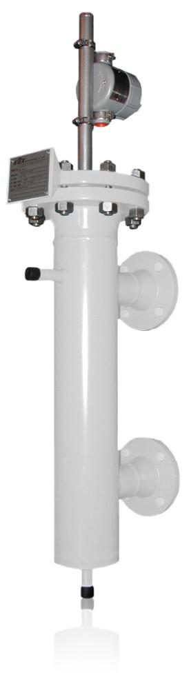
81
82 LS Series ABB s LS Series Mechanical Level Switches are the most rugged and durable liquid point-level detection products in the industrial marketplace today. ABB innovations such as the one-step switch point adjust and the hermetically sealed/dual compartment switching mechanism have eliminated the need for bulky housing covers that are associated with cracking, moisture ingress, high temperature fatigue, and ultimately switch failure. This configuration guide contains general guidelines and ordering data that will assist you in selecting the best float or displacer operated switch for your specific fluid level application. These switches are available in flanged or sealed chambers or as insertion models. ABB has over 100 configurations available.
83 LS Series Features & Options General Over 10,000 global installations in applications ranging from condensate to CO2 to crude oil Easily retrofitted to most competitor models Designed to handle specific gravities as low as 0.25, temperatures as high as 1000 F (538 C), and pressures up to 4500 psi (310 bar) Choose from eight (8) standard designs and six (6) different switching mechanisms Worldwide delivery Five year manufacturer warranty Chambers Choices for chamber material include: Carbon Steel, 316 Stainless Steel, Duplex Stainless Steel, Hastelloy C-276, Hastelloy B-3, and P11 and P91 Chrome Molly Steel. Flanged models have standard slip-on top access connection flanges. Weld-neck flanges are optional. Designed to guidelines of ASME B31.1 and B31.3 All welders and fabrication procedures are qualified and maintained per ASME Certification to NACE MRO175 and MRO103 is available Sensing Elements Each float and displacer is precision fabricated to indicate true fluid level. Choices for float and displacer materials include: 316 Stainless Steel, Hastelloy C-276, and Titanium (Grades 2 and 5). Ceramic is also available for displacers. Process Connections A wide variety of process connection types include: Flanges (slip-on, weld-neck), Socket Weld, and Threaded (NPT) Available flange ratings and sizes include: ASME, DIN, HG, and most International and customer specified flange types Switching Mechanisms All stainless steel housing construction with NEMA 4X ratings Temperature ratings available from -320 F (-190 C) to 1000 F (538 C) Choices for switching mechanism types include: Reed, Cam Action, and Pneumatic Available switching mechanisms are hermetically sealed, standard open contacts, or pneumatic contacts Agency Listings for most switches include: FM, CSA, and ATEX Options Custom Calibration and Switch Point High Temperature and Cryogenic Insulation Steam Tube and Electrical Heat Tracing Vent, Drain, and Process Isolation Valves Stilling Wells and Support Tubes for Turbulent Conditions Quality Certifications ABB is the only level gauge manufacturer in North America to hold the following certifications: ASME (U, S, and UM Stamps), PED, and National Boiler Certification

84 LS Series Applications & Basics OIL AND GAS Separator levels A P P L I C A T I O N S PETROCHEMICAL Catalytic Cracker Distillation Fractionation Hydrotreater/Reformer Coker Flare Knockout Tank POWER Fuel Storage Steam Turbine Drip Legs Hotwell Condenser Feed Water Heaters Demineralization Tanks Ash Precipitator/Scrubber Steam Drum Level Lube Oil Systems CHEMICAL & OTHER Storage & Batch Tank Level High Level Alarm Safety Shutdown Water/Wastewater Treatment Tanks Pulp Processing Tanks Lube Oil Tanks Sump Control LS Series Description and Operation Basics The LS Series is a single or multi point, fluid-level switch. The device consists of a float (or displacer) with an attached magnet and a switch post to house the moving magnet and to support the switch mechanism. The switch post is mounted on either a top entry process connection or to the top of a mechanical cage or chamber. Process connections are typically flanges, NPT, or socket weld connections. Chambers have connections on the side and/or bottom to attach to the side of a tank. Movement of the float (or displacer) is typically limited to the range required to activate the switch mechanism at a specified level. The LS Series can be a float or displacer operated, magnetically coupled level switch. As the fluid level in the vessel rises or falls, the position of the float or displacer changes with it. Magnets inside the switch post, attached to the float or displacer, move with the changing level as well. A switch mechanism, attached to the exterior of the switch post, detects movement of the magnet past its location, and transfers the contact positions. Use of the LS Series instead of the conventional bulky housing cage switch allows easy access to the switch mechanism and there are no seals or diaphragms to wear out. Installation of isolation valves on the inlet and outlet of the chamber allows removal of the entire unit without draining the vessel.
85 Mechanical Level Switches Table of Contents Section Page Quality Manufacturing Switch Mechanism Comparison 6 Chamber Comparison 7 Fundamentals Float Switches 8 Displacer Switches 8 How to Order 9 Float Switches 500/510 Series - Top Mount Float Series - Flanged Chamber Float Series - Sealed Chamber Float 27 Displacer Switches 550/560 Series - Top Mount Displacer Series - Flanged Chamber Displacer Series - Sealed Chamber Displacer 33 Switching Mechanisms and Housings Switches 39 Accessories High Temperature & Cryogenic Isolation Insulation 41 Vent, Drain & Process Isolation Valves 42 Stilling Wells & Support Tubes 43 Appendix Pipe Pressure Ratings (Table 1) 44 Flange Pressure Ratings (Table 2) 46 Process Connection Configuration (Tables 3 & 4) 47 Conversions (Table 5) 51
86 Switch Mechanism Comparison Quality Manufacturing Switching Mechanism Comparison The ABB standard switching mechanism is a magnetically actuated double pole double throw (DPDT) switch. ABB offers a variety of magnetically actuated switch mechanisms (reed, cam-action and pneumatic style) with SPDT, DPDT, or pneumatic outputs. When a ABB switch mechanism (single or multiple) is mounted on a LS Series mechanical switch, it can sense a high or low level within a vessel. The unique magnetic coupling action eliminates the need for seals, diaphragm springs, or torque tubes because there is no physical contact with the process. The switch configuration also has no process connections which ensures complete isolation from the process. The 360 adjustable switch mechanism does not require the removal of the conventional bulky cover and can be easily positioned at the desired switch point. The compact, maintenance free design, requires no periodic cleaning or operational checks and contains hermetically sealed contacts that ensure high reliability and extended product life. ABB Standard with MS41 Switching Mechanism Competitor Standard


 #DGR-0036-QS-166-02 Authorized to apply the NB mark and register boilers, pressure vessels, or other pressure retaining")
87 Chamber Comparison Quality Manufacturing ABB uses high quality design, ASTM materials and ASME construction to provide a significantly higher standard product than our competition. With ABB products, a customer never needs to worry if they are getting a good design all standard products meet the following criteria as a minimum. ABB Standard Chamber Other Manufacturer s Chamber ABB is the only North American level instrument company holding ASME, PED and National Boiler certifications. Any LS Series can be manufactured to following certifications and/or most customer specific supplied standards U # 26,831 Manufacturer of Pressure Vessels UM #26,832 Manufacturer of Miniature of Pressure Vessels S #26,830 Manufacturer and Assembly of Power Boilers B31.1 Power Piping B31.3 Process Piping Pressure Equipment Directive (97/23/EC) #DGR-0036-QS Authorized to apply the NB mark and register boilers, pressure vessels, or other pressure retaining items with the National Board in accordance with its provisions. Scope of Authorization is in reference to ASME Stamps S and U.
88 Float & Displacer Switches Fundamentals Float Operated Level Switches Model Series 500, 510, 600, 700 The float rides on the process fluid and tracks with the liquid level movement. As the fluid level in the vessel (or external cage) rises or falls, the position of the float changes. Magnets attached to a float guide rod (located inside the sensing tube) also move with the changing level. A switch mechanism (electrical or pneumatic) attached to the exterior of the sensing tube is actuated by a rising level and deactuated by a falling level. Floats can utilize multiple switching mechanisms. arrangements. Consult the factory for special float switching Displacer Operated Level Switches Model Series 550, 560, 800, 900 Displacer switches offer an alternative means of fluid level measurement different from the traditional float device. While a float follows the liquid level, a displacer remains partially or completely submerged. The buoyancy of the displacer is increased as it becomes covered by more liquid. Therefore, when the displacer weight drops below the spring tension (rising level), the switch mechanism is actuated. Hence, when the displacer weight increases to that greater than the spring tension (falling level), the switch mechanism is de-actuated. Displacer switches can be utilized in some high pressure and low specific gravity applications where float designs are cost prohibitive or impossible to implement.

89 Series LS How To Order Model Number Format How to Order: Step 1: Step 2: Step 3: Step 4: Step 5: Step 6: /a/ Select Process Connection Configuration Choose a mechanical level switch model series based on maximum working pressure, maximum temperature and minimum specific gravity. /b/ Select Access Connection or Chamber Material /c/ Select Process Connection Size, Type & Rating /d/ Select Switching Mechanism Type /e/ Select Insulation /f/ Select Options
90 Series LS 500/510 Model Number Selection: Step 1 Top Mount Float Series Model Number Formats Series LS 5xx - Top Mounted Float 50x - Flanged Process Connection Example Application Data: Pressure 26bar, Temperature 225 C, S.G..68, 2 4 Flanged Process Connection, 32 3/8 Pneumatic Switch Point Location Example: LS502/CST/SR43/F/IP/SP=32 3/8in. Model (Series) (a) Access Connection Material (b) Access Connection Size, Type & Rating (c) Switching Mechanism Type (d) Insulation (e) Options (f) 502 CST SR43 F IP SP=32 3/8 Step 1: /a/ Select PROCESS CONNECTION CONFIGURATION 50x Flanged 51x NPT Note: For both the 50x and 51x, use the table below to select model series. Top Mount Float Series Model Series Pressure at Indicated Temperature 100 F (psig) 37.7 C (bar) 450 F (psig) 232 C (bar) Float Mat'l Code Minimum S.G. 5x T2.4 5x S6.68 5x S6.52 Float Materials: 316 SS (S6) is the standard. The following materials and others are available. Hastelloy C276; Titanium Gr2 and Titanium Gr5. Construction materials are determined by application specifics (i.e. temperature, pressure and specific gravity). Consult ABB factory for other materials and process conditions not listed.
91 Series LS 550/560 Model Number Selection: Step 1 Top Mount Displacer Series Model Number Formats Series LS 5xx - Top Mounted Displacer 56x - Threaded Process Connection Example Application Data: Pressure: 17 bar, Temperature: 35 C, S.G.: 0.76, NPT Process Connection, Switch Point Location 20 3/4 Example: LS562/SS6/P15/E/X/SP=20 3/4in. Model (Series) (a) Access Connection Material (b) Access Connection Size, Type & Rating (c) Switching Mechanism Type (d) Insulation (e) Options (f) 562 SS6 P15 E X SP=20 3/4 Step 1: /a/ Select PROCESS CONNECTION CONFIGURATION 55x Flanged 56x NPT Note: For both the 55x and 56x, use the table below to select model series. Top Mount Displacer Series Pressure at Indicated Temperature Model Series 100 F (psig) 37.7 C (bar) 450 F (psig) 232 C (bar) Displacer Mat'l Minimum S.G. 5x S6.6 5x S6.6 Displacer Materials: 316 SS (S6) is the standard. The following materials and others are available. Hastelloy C276; Titanium Gr2, Titanium Gr5 and Porcelain. Construction materials are determined by application specifics (i.e. temperature, pressure and specific gravity). Consult ABB factory for other materials and process conditions not listed.
92 Series LS 500/510/550/560 Model Number Selection: Steps 2-6 Step 2: /b/ ACCESS CONNECTION MATERIAL CST CARBON STEEL (STANDARD) SS6 316 SS DUP DUPLEX STAINLESS STEEL HSB HASTELLOY B-3 HSC HASTELLOY C-276 P11 P %CHROME, MOLYBDENUM STEEL P91 P91 9% CHROME, MOLYBDENUM STEEL O CUSTOM 11 Step 3: /c/ ACCESS CONNECTION SIZE TYPE & RATING 1 SEE TABLES 3 & 4 (p46-49) IN APPENDIX O CUSTOM 10 Step 4: 4 /d/ A B SWITCHING MECHANISM TYPE 2 1 AMP SPDT REED SWITCH MS30 MS30EX NOTE: TYPE A & B NOT COMPATIBLE WITH 55X/56X SERIES 10AMP DPDT CAM ACTION SWITCH Step 5: 4 /e/ INSULATION 3 X IF NO INSULATION INSULATION FLANGE - RATED UP TO 900 F (482 C) MAX IP INSULATION PAD - ALL SERVICES >180 F (82 C) PNEUMATIC SWITCHES ONLY ALL SERVICES >300 F (149 C) ELECTRIC SWITCHES ONLY O CUSTOM 10 Step 6: 4,7 /f/ OPTIONS X NO OPTIONS IL INSERTION LENGTH CX CUSTOM CALIBRATION 5 SW STILLING WELL 8 ST SUPPORT TUBE 8 IM INTERFACE LEVEL MEASUREMENT 9 O CUSTOM 10 SP SWITCH POINT LOCATION 6 NOTE: REFERENCE MODEL NUMBER SELECTION NOTES ON THE FOLLOWING PAGE C D E F G MS40 MS40/EX MS41 HERM SEALED (STANDARD) PNEUMATIC SWITCH PS35 PS45
93 Series LS 500/550 Model Number Selection: Steps 2-6 NOTES: 1. See Flange Pressure Rating Table in Appendix. Information in these tables is taken from ASME Standards. DIN, HG, or other International Flange Types require factory consultation. 2. See Switching Mechanisms and Housings on page See Switch Mechanism Product Data Sheets for specifications. 3. See Insulation Descriptions on page 40; Insulation Flange (IF) is recommended for personnel safety. 4. Multiple Options: Separate multiple options with semi-colon (;) Example:...x/B = 2-11/16 in; SW = CX - Custom Calibration: C + B or C for required dimension (not B and C ) and engineering units (mm, in, cm) Example:. x / CB=2-11/16 in;.. See Calibration Dimensions. 6. Customer to specify switch point location to nearest 1/8 or specify CX 7. Only applicable if retrofitting Top Insertion Model into existing Chamber. See Figure 1 below. Customer to specify existing Chamber Length (P) and Chamber ID. 8. See Stilling Well (SW) and Support Tubes (ST) descriptions below in Figure 2 and on page Interface Level Measurement (IM) requires special consideration. Consult factory for details. 10. For options and selections not listed, write requirements after model number. Contact the ABB factory for price and availability. Figure 1 Support Tube w/flange Stilling Well w/flange Support Tube w/npt Stilling Well w/npt Figure 2
94 Series LS 500/510/550/560 Dimensions Calibration Dimensions for LS 500/510/550/560 Series Dimensions in this catalog are for reference only. They may be changed without notice. Contact the factory for certified drawings for a particular model number. Note: It is important to consider the installation configuration when selecting the process connection. Be sure that the float will fit through the process connection, or that the vessel has access to attach the float from inside the vessel after instrument installation. Model Float Size 500/510 Series (Float) Minimum Minimum Insertion Maximum Insertion Opening Size in mm in mm 5x1 TBD TBD 4-1/ x2 TBD TBD 4-1/ x3 TBD TBD 4-1/ Note: For longer Insertion Length, consult ABB factory. 50x Flanged 51x NPT Model 550/560 Series (Displacer) Displacer Size Maximum Insertion Length in mm 5x1 TBD x2 TBD x Flanged 56x Flanged Note: For longer Insertion Length, consult ABB factory.
95 Series LS 600 Model Number Selection: Step 1 Flanged Chamber Float Series Model Number Formats Series LS 6xx - Flanged Chamber Float 61x - Side/Side Process Connections Example Application Data: Pressure 52bar, Temperature 230 C, S.G..68, 0.61, 2 Flange Process Connection, Pneumatic Output, 3/4 Vent Valve Example: LS614/CST/N3F0W9/N74-WR26/F/IH2;IF/VV; C=300mm Step 1: /a/ Process Connection Size, Type & Rating Select PROCESS CONNECTION CONFIGURATION Switching Mechanism Type Model (Series) (a) Chamber Material (b) (c) (d) Insulation (e) Options (f) 614 CST N3F0W9/N74-WR26 F IH2;IF VV; C=300mm 61x Side/Side 62x Side/Side/Drain 63x Side/Bottom A Side/Side Carbon Steel Chamber (A106 GrB) Model Series 100 F (psig) 37.7 C (bar) Pressure at Indicated Temperature 450 F (psig) 232 C (bar) 750 F (psig) 399 C (bar) 1000 F (psig) 538 C (bar) Float Mat'l Code Minimum S.G. 6x TBD x TBD x TBD x TBD x TBD x TBD x TBD x TBD x TBD TBD TBD TBD TBD 0.77 Stainless Steel Chamber (316SS) Float materials: 316 SS (S6) is the standard. The following materials and others are available. Hastelloy C276; Titanium Gr2 and Titanium Gr5. Construction materials are determined by application specifics (i.e. temperature, pressure and specific gravity). Consult ABB factory for other chamber materials and process conditions not listed. Model Series 100 F (psig) Pressure at Indicated Temperature 37.7 C (bar) 450 F (psig) 232 C (bar) 750 F (psig) 399 C (bar) 1000 F (psig) 538 C (bar) Float Mat'l Code Minimum S.G. 6x TBD x TBD x TBD x TBD x TBD x TBD x TBD x TBD x TBD TBD TBD TBD TBD 0.77
96 Series LS 600 Model Number Selection: Steps 2-6 Step 2: /b/ CHAMBER MATERIAL CST CARBON STEEL (STANDARD) SS6 316 SS DUP DUPLEX STAINLESS STEEL HSB HASTELLOY B-3 HSC HASTELLOY C-276 P11 P %CHROME, MOLYBDENUM STEEL P91 P91 9% CHROME, MOLYBDENUM STEEL O CUSTOM 11 Step 3: /c/ PROCESS CONNECTION SIZE 1,9, 10 TYPE & RATING SEE TABLES 3 & 4 (p46-49) IN APPENDIX O CUSTOM 12 Step 4: 4 /d/ A B C D E F G SWITCHING MECHANISM TYPE 2 1 AMP SPDT REED SWITCH MS30 MS30EX 10AMP DPDT CAM ACTION SWITCH MS40 MS40/EX MS41 HERM SEALED (STANDARD) PNEUMATIC SWITCH PS35 PS45 Step 5: 4 /e/ INSULATION 3 X NO INSULATION IP INSULATION PAD - ALL SERVICES >180 F (82 C) PNEUMATIC SWITCHES ONLY ALL SERVICES >300 F (149 C) ELECTRIC SWITCHES ONLY IH1 IH1D IH2 IH2D IH3 IH3D IF IL1 IL2 IL3 HIGH TEMP. INSULATION; FLOAT CHAMBER ONLY; 1/2 THICK, 250 F (121 C) MAX HIGH TEMP. INSULATION; FLOAT CHAMBER & VENT/ DRAIN FLANGES; 1/2 THICK, 250 F (121 C) MAX HIGH TEMP. INSULATION; FLOAT CHAMBER ONLY; 1 THICK, 500 F (260 C) MAX HIGH TEMP. INSULATION; FLOAT CHAMBER & VENT/ DRAIN FLANGES; 1 THICK, 500 F (260 C) MAX HIGH TEMP. INSULATION; FLOAT CHAMBER ONLY; 2 THICK, 900 F (482 C) MAX HIGH TEMP. INSULATION; FLOAT CHAMBER & VENT/ DRAIN FLANGES; 2 THICK, 900 F (482 C) MAX INSULATION FLANGE - RATED UP TO 900 F (482 C) MAX CRYOGENIC INSULATION; 2 THICK; SINGLE LAYER; -100 F (-73 C) MINIMUM CRYOGENIC INSULATION; 3 THICK; DOUBLE LAYER; -200 F (-129 C) MINIMUM CRYOGENIC INSULATION; 4 THICK; DOUBLE LAYER; -320 F (-196 C) MINIMUM O CUSTOM 12 Step 6: 4 /h/ OPTIONS X NO OPTIONS CX CUSTOM CALIBRATION 5 LX CUSTOM CHAMBER LENGTH 6 VV VENT VALVE 7 DV DRAIN VALVE 7 IV ISOLATION VALVE 7 IM INTERFACE LEVEL MEASUREMENT 8 TT1 STEAM TRACE TUBING ET1xx ELECTRIC TRACING; CLASS 1, DIV 2, GP BCD;221 F (105 C) MAX, FIXED SET POINT CONTROL 11 ET2x ELECTRIC TRACING; CLASS 1, DIV 2, GP BCD;400 F (204 C) MAX, ADJUSTABLE SETPOINT CONTROL 11 ET3x ELECTRIC TRACING; CLASS 1, DIV 2, GP BCD;800 F (427 C) MAX, ADJUSTABLE SETPOINT CONTROL 11 G GUSSETS ON PROCESS CONNECTION (HIGH VIBRATION APPLICATIONS) O CUSTOM 12 NOTE: REFERENCE MODEL NUMBER SELECTION NOTES ON THE FOLLOWING PAGE
97 Series LS 600 Model Number Selection: Steps 2-6 NOTES: 1. See Flange Pressure Rating Table in Appendix. Information in these tables is taken from ASME Standards. DIN, HG, or other International Flange Types require factory consultation. 2. See Switching Mechanisms and Housings on page See Switch Mechanism Product Data Sheets for specifications. 3. See Insulation Descriptions on page 40; Insulation Jackets (IH) & Insulation Flange Covers are recommended for personnel safety. 4. Multiple Options: Separate multiple options with semi-colon (;) Example:...x/B = 2-11/16 in; H = 287mm;.. 5. CX - Custom Calibration: C + B or C for required dimension (not B and C ) and engineering units (mm, in, cm) Example:. x / CB=2-11/16 in;.. See Calibration Dimensions. 6. LX - Custom Length: L + D or H for required dimension (not D and H ) and engineering units (mm, in, cm) Example:. x / LH = 287mm;.. See Dimension Tables. 7. See Valve Description on Page 41. Vent Valve (VV), Drain Valve (DV), Isolation Valves (IV) Customer to specify valve type and size. 8. Interface Level Measurement (IM) requires special consideration. Consult factory for details. 9. For Available Process Connections, see Tables 3 and 4 (p46-49) in Appendix. 10. Chamber Access Flange Types will be the same as Process Connections. If Process Connections are not flanges, Raised Face Slip-ons will be the standard (unless otherwise specified). Use option O if flange type differs from process connection. 11. Specify power supply 1) 110, 2) 220, 3) 277 OR 4) 440 VAC) (ex. ET21= ET2 with 110VAC power supply). For ET1xx series only, specify setpoint A) 35, B) 45, C) 60, D) 90 or E) 185 F (1.7, 7.2, 15.6, 32.2, or 85 C) (ex. ET11A = ET1 with 110VAC power supply and a setpoint of 35 F) 12. For options and selections not listed, write requirements after model number. Contact the ABB factory for price and availability.
98 Series LS 600 Calibration Dimensions Calibration Dimensions for LS 600 series 1. B is the distance that the switch trips on rising level at the specified S.G. 2. C is the distance that the switch resets on falling level at the specified S.G. 3. The B dimension is the default switch calibration setting. 4. The C dimension will vary depending on the particular switch unit specified. 5. If a different B or the C dimension is required, it should be stated as shown under Options. 6. Calibration accuracy is +/- 1/4 (6mm) 600 Series 6x1 S.G. B C /16 3-3/ /16 4-1/ /4 4-9/ /16 4-7/ /16 5-1/ /16 5-3/8 600 Series 6x2 S.G. B C /16 3-1/ / /2 4-3/ /16 4-1/ /4 4-3/ / Series 6x3 S.G. B C /16 3-3/ /8 4-1/ /8 4-7/ /16 4-3/ / / /8 5-1/8 600 Series 6x4 S.G. B C /2 3-1/ / / /8 4-3/ /4 4-1/ /2 4-11/ /16 4-7/8 600 Series 6x5 S.G. B C /4 4-1/ /16 4-3/ /16 5-5/ /16 5-7/ /16 6-1/ /8 6-9/ Series 6x6; 6x7 S.G. B C /16 3-7/ /8 3-5/ /4 3-7/ /8 4-1/ /8 4-1/ /16 4-3/8 600 Series 6x8; 6x9 S.G. B C /8 3-1/ / /16 4-1/ /4 4-3/ / /4 4-13/16
99 Series LS 600 Chamber Dimensions Chamber Dimensions for LS 600 series See Tables on page 19 for dimensions for selected process connection size. Drawings not to scale. 61x Side/Side 62x Side/Side/Drain 63x Side/Bottom (NPT SW only) 63x Side/ Bottom
100 Series LS 600 Chamber Dimensions Dimension Tables 1 Process Connection Dimension Table D* E* F H K L Inches mm Inches mm inches mm inches mm inches mm inches mm 6x1 6x2 6x3 6x4 10-1/ /16 94 TBD TBD TBD TBD TBD TBD 10-3/ /4 121 TBD TBD TBD TBD TBD TBD 6x5 12-5/ /4 146 TBD TBD TBD TBD TBD TBD 6x6 6x /16 81 TBD TBD TBD TBD TBD TBD 6x8 10-1/ /16 94 TBD TBD TBD TBD TBD TBD * These dimensions apply to Model 63x Side/Bottom with Threaded or Socket Flange Type only (see p18) 1-1/2 Process Connection Dimension Table D* E* F H K L Inches mm Inches mm inches mm inches mm inches mm inches mm 6x1 6x2 6x3 6x4 10-9/ /4 95 TBD TBD TBD TBD TBD TBD 10-7/ / TBD TBD TBD TBD TBD TBD 6x / / TBD TBD TBD TBD TBD TBD 6x6 6x /4 83 TBD TBD TBD TBD TBD TBD 6x8 10-9/ /4 95 TBD TBD TBD TBD TBD TBD * These dimensions apply to Model 63x Side/Bottom withthreaded or Socket Flange Type only (see p18) 2 Process Connection Dimension Table D* E* F H K L Inches mm Inches mm inches mm inches mm inches mm inches mm 6x1 6x2 6x3 6x / /8 98 TBD TBD TBD TBD TBD TBD 10-9/ / TBD TBD TBD TBD TBD TBD 6x / / TBD TBD TBD TBD TBD TBD 6x6 6x7 -- NA-- -- NA-- --NA-- -- NA-- TBD TBD TBD TBD TBD TBD 6x / /8 98 TBD TBD TBD TBD TBD TBD * These dimensions apply to Model 63x Side/Bottom withthreaded or Socket Flange Type only (see p18)
101 Series LS 700 Model Number Selection: Step 1 Sealed Chamber Float Series Model Number Format Series LS 7xx - Sealed Chamber Float Series LS 73x - Side/Bottom Process Connections 35 C, S.G. 0.5, Example:LS738/SS6/C1W3/SC13/B/X/LH=315mm Process Connection Size, Type & Rating Example Application Data: Pressure 27bar, Temperature 35 C, S.G. 0.5, 1 Process Connection Switching Mechanism Type Model (Series) (a) Chamber Material (b) (c) (d) Insulation (e) Options (f) 738 SS6 C1W3/SC13 B X LH=315mm Step 1: /a/ Select PROCESS CONNECTION CONFIGURATION 71x Side/Side 72x Side/Side/Drain 73x Side/Bottom A Side/Side Carbon Steel Chamber (A106 GrB) Model Series 100 F (psig) 37.7 C (bar) Pressure at Indicated Temperature 450 F (psig) 232 C (bar) 750 F (psig) 399 C (bar) 1000 F (psig) 538 C (bar) Float Mat'l Code Minimum S.G. 7x TBD.37 7x TBD.54 7x TBD.64 7x TBD.93 7x TBD.5 7x TBD.63 7x TBD.61 7x TBD.38 7x TBD.65 Stainless Steel Chamber (316SS) Model Series 100 F (psig) 37.7 C (bar) Pressure at Indicated Temperature 450 F (psig) 232 C (bar) 750 F (psig) 399 C (bar) 1000 F (psig) 538 C (bar) Float Mat'l Code Minimum S.G. 7x TBD.37 7x TBD.54 Float materials: 316 SS (S6) is the standard. The following materials and others are available. Hastelloy C276; Titanium Gr2 and Titanium Gr5. Construction materials are determined by application specifics (i.e. temperature, pressure and specific gravity. Consult ABB factory for other chamber materials and process conditions not listed. 7x TBD.64 7x TBD.93 7x TBD.5 7x TBD.63 7x TBD.61 7x TBD.38 7x TBD.65
102 Series LS 700 Model Number Selection: Steps 2-6 Step 2: /b/ CHAMBER MATERIAL CST CARBON STEEL (STANDARD) SS6 316 SS DUP DUPLEX STAINLESS STEEL HSB HASTELLOY B-3 HSC HASTELLOY C-276 P11 P %CHROME, MOLYBDENUM STEEL P91 P91 9% CHROME, MOLYBDENUM STEEL O CUSTOM 11 Step 3: /c/ PROCESS CONNECTION SIZE TYPE & RATING 1,9 SEE TABLES 3 & 4 (p46-49) IN APPENDIX O CUSTOM 11 Step 4: 4 /d/ SWITCHING MECHANISM TYPE 2 A B C D E 1 AMP SPDT REED SWITCH MS30 MS30EX 10AMP DPDT CAM ACTION SWITCH MS40 MS40/EX MS41 HERM SEALED (STANDARD) Step 5: 4 /e/ INSULATION 3 X NO INSULATION IP INSULATION PAD - ALL SERVICES >180 F (82 C) PNEUMATIC SWITCHES ONLY ALL SERVICES >300 F (149 C) ELECTRIC SWITCHES ONLY IH1 IH1D IH2 IH2D IH3 IH3D IL1 IL2 IL3 HIGH TEMP. INSULATION; FLOAT CHAMBER ONLY; 1/2 THICK, 250 F (121 C) MAX HIGH TEMP. INSULATION; FLOAT CHAMBER & VENT/ DRAIN FLANGES; 1/2 THICK, 250 F (121 C) MAX HIGH TEMP. INSULATION; FLOAT CHAMBER ONLY; 1 THICK, 500 F (260 C) MAX HIGH TEMP. INSULATION; FLOAT CHAMBER & VENT/ DRAIN FLANGES; 1 THICK, 500 F (260 C) MAX HIGH TEMP. INSULATION; FLOAT CHAMBER ONLY; 2 THICK, 900 F (482 C) MAX HIGH TEMP. INSULATION; FLOAT CHAMBER & VENT/ DRAIN FLANGES; 2 THICK, 900 F (482 C) MAX CRYOGENIC INSULATION; 2 THICK; SINGLE LAYER; -100 F (-73 C) MINIMUM CRYOGENIC INSULATION; 3 THICK; DOUBLE LAYER; -200 F (-129 C) MINIMUM CRYOGENIC INSULATION; 4 THICK; DOUBLE LAYER; -320 F (-196 C) MINIMUM O CUSTOM 11 Step 6: 4 /h/ OPTIONS X NO OPTIONS CX CUSTOM CALIBRATION 5 LX CUSTOM CHAMBER LENGTH 6 VV VENT VALVE 7 DV DRAIN VALVE 7 IV ISOLATION VALVE 7 IM INTERFACE LEVEL MEASUREMENT 8 TT1 STEAM TRACE TUBING ET1xx ELECTRIC TRACING; CLASS 1, DIV 2, GP BCD; 221 F(105 C) MAX, FIXED SET POINT CONTROL 10 ET2x ELECTRIC TRACING; CLASS 1, DIV 2, GP BCD;400 F(204 C) MAX, ADJUSTABLE SETPOINT CONTROL 10 ET3x ELECTRIC TRACING; CLASS 1, DIV 2, GP BCD;800 F (427 C) MAX, ADJUSTABLE SETPOINT CONTROL 10 G GUSSETS ON PROCESS CONNECTION (HIGH VIBRATION APPLICATIONS) O CUSTOM 11 NOTE: REFERENCE MODEL NUMBER SELECTION NOTES ON THE FOLLOWING PAGE F G PNEUMATIC SWITCH PS35 PS45
103 Series LS 700 Model Number Selection: Steps 2-6 NOTES: 1. See Flange Pressure Rating Table in Appendix. Information in these tables is taken from ASME Standards. DIN, HG, or other International Flange Types require factory consultation. 2. See Switching Mechanisms and Housings on page See Switch Mechanism Product Data Sheets for specifications. 3. See Insulation Descriptions on page 40; Insulation Jackets (IH) & Insulation Flange Covers (IF) are recommended for personnel safety. 4. Multiple Options: Separate multiple options with semi-colon (;) Example:...x/B = 2-11/16 in; H = 287mm;.. 5. CX - Custom Calibration: C + B or C for required dimension (not B and C ) and engineering units (mm, in, cm) Example:. x / CB=2-11/16 in;.. See Calibration Dimensions. 6. LX - Custom Length: L + D or H for required dimension (not D and H ) and engineering units (mm, in, cm) Example:. x / LH = 287mm;.. See Dimension Tables. 7. See Valve Description on Page 41. Vent Valve (VV), Drain Valve (DV), Isolation Valves (IV) Customer to specify valve type and size. 8. Interface Level Measurement (IM) requires special consideration. Consult factory for details. 9. For Available Process Connections, see Tables 3 and 4 (p46-49) in Appendix. 10. Specify power supply 1) 110, 2) 220, 3) 277 & 4) 440 VAC) (ex. ET21= ET2 with 110VAC power supply). For ET1xx series only, specify setpoint A) 35, B) 45, C) 60, D) 90 or E) 185 F (1.7, 7.2, 15.6, 32.2, or 85 C) (ex. ET11A = ET1 with 110VAC power supply and a setpoint of 35 F) 11. For options and selections not listed, write requirements after model number. Contact the ABB factory for price and availability.
104 Series LS 700 Calibration Dimensions Calibration Dimensions for LS 700 series 1. B is the distance that the switch trips on rising level at the specified S.G. 2. C is the distance that the switch resets on falling level at the specified S.G. 3. The B dimension is the default switch calibration setting. 4. The C dimension will vary depending on the particular switch unit specified. 5. If a different B or the C dimension is required, it should be stated as shown under Options. 6. Calibration accuracy is +/- 1/4 (6mm) 700 Series 7x1 S.G. "B" "C" /16" 3-1/2" " 3-3/4" /16" 4-3/8" /8" 4-3/4" /4" 5-1/16" /16" 5-1/4" 700 Series 7x2 S.G. "B" "C" /16" 3-3/4" /16" 4-1/8" /4" 4-9/16" /16" 4-7/8" /16" 5-1/8" /16" 5-3/8" 700 Series 7x3 S.G. "B" "C" /16" 3-1/2" " 3-3/4" /2" 4-13/16" /16" 4-1/2" /4" 4-3/4" /2" 5" 700 Series 7x4 S.G. "B" "C" /8" 3-1/2" 1.0 3" 3-3/4" /16" 4-1/16" /4" 4-3/8" 1.3 4" 4-9/16" /4" 4-13/16" 700 Series 7x5 S.G. "B" "C" /16" 3-3/8" /8" 4-1/16" /8" 4-7/16" /16" 4-3/4" /16" 4-15/16" /8" 5-1/8" 700 Series 7x6 S.G. "B" "C" /8" 3-3/4" /16" 4-1/16" /8" 4-3/8" /16" 4-9/16" /16" 4-3/4" /8" 4-7/8" 700 Series7x7 S.G. "B" "C" /2" 3-1/4" /16" 3-13/16" /16" 4-3/16" /4" 4-1/2" /2" 4-3/4" /16" 4-7/8" 700 Series 7x8 S.G. "B" "C" /4" 4-1/16" /16" 4-3/8" /16" 5-5/16" /16" 5-7/8" /16" 6-1/4" /8" 6-9/16" 700 Series7x9 S.G. "B" "C" /16" 3-7/16" /8" 3-5/8" /4" 3-7/8" /8" 4-1/16" /8" 4-1/4" /16" 4-3/8"
105 Series LS 700 Chamber Dimensions Chamber Dimensions for LS 700 series See Tables on page 25 for dimensions for selected process connection size. Drawings not to scale. 71x Side/Side 72x Side/Side/Drain 73x Side/Bottom (NPT SW only) 73x Side/ Bottom
106 Series LS 700 Chamber Dimensions Dimension Tables 1 Process Connection Dimension Table D* E* F H K L inches mm inches mm inches mm inches mm inches mm inches mm 7x1 10-3/ /4 121 TBD TBD TBD TBD TBD TBD 7x2 7x3 7x4 7x5 10-1/ /16 94 TBD TBD TBD TBD TBD TBD 7x6 7x7 7x8 10-3/8 12-5/ /4 5-3/ TBD TBD TBD TBD TBD TBD TBD TBD TBD TBD TBD TBD 7x /16 81 TBD TBD TBD TBD TBD TBD * These dimensions apply to Model 63x Side/Bottom with Threaded or Socket Flange Type only (see p.24) 1-1/2 Process Connection Dimension Table D* E* F H K L inches mm inches mm inches mm inches mm inches mm inches mm TBD TBD TBD TBD TBD TBD /4 95 TBD TBD TBD TBD TBD TBD 7x5 7x1 7x2 10-7/16 7x3 10-7x4 9/ / / TBD TBD TBD TBD TBD TBD / TBD TBD TBD TBD TBD TBD 7x8 7x6 10-7x7 7/ / / TBD TBD TBD TBD TBD TBD * These dimensions apply to Model 63x Side/Bottom with Threaded or Socket Flange Type only (see p.24) 2 Process Connection Dimension Table D* E* F H K L inches mm inches mm inches mm inches mm inches mm inches mm 7x1 7x2 7x3 7x4 10-9/ / TBD TBD TBD TBD TBD TBD 10-11/ /8 99 TBD TBD TBD TBD TBD TBD 7x5 10-9/ / TBD TBD TBD TBD TBD TBD 7x6 7x7 10-9/ / TBD TBD TBD TBD TBD TBD 7x / / TBD TBD TBD TBD TBD TBD * These dimensions apply to Model 63x Side/Bottom with Threaded or Socket Flange Type only (see p.24)
107 Series LS 800 Model Number Selection: Step 1 Flanged Chamber Displacer Series Model Number Formats Series LS 8xx - Flanged Chamber Displacer 82x - Side / Side/ Drain Process Connections 35 C, S.G. 0.5 Example: LS824/SS6/GEGE/SJ315/D/IH2D/CB=2-11/16 Step 1: Process Connection Size, Type & Rating Example Application Data: Pressure 150bar, Temperature 35 C, S.G. 0.5, 3 Flange Process Connection Switching Mechanism Type Model (Series) (a) Chamber Material (b) (c) (d) Insulation (e) Options (f) 824 SS6 GEGE/SJ315 D IH2D CB=2-11/16 81x Side/Side 82x Side/Side/Drain 83x Side/Bottom A Side/Side Carbon Steel Chamber (A106 GrB) Pressure at Indicated Temperature Model Series 100 F (psig) 37.7 C (bar) 450 F (psig) 232 C (bar) Float Mat'l Code Minimum S.G. 8x S6.4 8x S6.4 8x S6.4 8x S6.4 Standard displacer units are not available above 450 F (232 C) Stainless Steel Chamber (316SS) Model Series 100 F (psig) Pressure at Indicated Temperature 37.7 C (bar) 450 F (psig) 232 C (bar) Float Mat'l Code Minimum S.G. 8x S6.4 8x S6.4 8x S6.4 8x S6.4 Standard displacer units are not available above 450 F (232 C) Displacer Materials: 316 SS (S6) is the standard. The following materials and others are available. Hastelloy C276; Titanium Gr2, Titanium Gr5 and Porcelain. Construction materials are determined by application specifics (i.e. temperature, pressure and specific gravity). Consult ABB factory for other chamber materials and process conditions not listed.
108 Series LS 800 Model Number Selection: Steps 2-6 Step 2: /b/ CHAMBER MATERIAL CST CARBON STEEL (STANDARD) SS6 316 SS DUP DUPLEX STAINLESS STEEL HSB HASTELLOY B-3 HSC HASTELLOY C-276 P11 P %CHROME, MOLYBDENUM STEEL P91 P91 9% CHROME, MOLYBDENUM STEEL O CUSTOM 11 Step 3: /c/ PROCESS CONNECTION SIZE 1,9, 10 TYPE & RATING SEE TABLES 3 & 4 (p46-49) IN APPENDIX O CUSTOM 12 Step 4: 4 /d/ C D E F G SWITCHING MECHANISM TYPE 2 10 AMP DPDT CAM ACTION SWITCH MS40 MS40/EX MS41 HERM SEALED (STANDARD) PNEUMATIC SWITCH PS35 PS45 Step 5: 4 /e/ INSULATION 3 X NO INSULATION IP INSULATION PAD - ALL SERVICES >180 F (82 C) PNEUMATIC SWITCHES ONLY ALL SERVICES >300 F (149 C) ELECTRIC SWITCHES ONLY IH1 IH1D IH2 IH2D IH3 IH3D IF IL1 IL2 IL3 HIGH TEMP. INSULATION; FLOAT CHAMBER ONLY; 1/2 THICK, 250 F (121 C) MAX HIGH TEMP. INSULATION; FLOAT CHAMBER & VENT/ DRAIN FLANGES; 1/2 THICK, 250 F (121 C) MAX HIGH TEMP. INSULATION; FLOAT CHAMBER ONLY; 1 THICK, 500 F (260 C) MAX HIGH TEMP. INSULATION; FLOAT CHAMBER & VENT/ DRAIN FLANGES; 1 THICK, 500 F (260 C) MAX HIGH TEMP. INSULATION; FLOAT CHAMBER ONLY; 2 THICK, 900 F (482 C) MAX HIGH TEMP. INSULATION; FLOAT CHAMBER & VENT/ DRAIN FLANGES; 2 THICK, 900 F (482 C) MAX INSULATION FLANGE - RATED UP TO 900 F (482 C) MAX CRYOGENIC INSULATION; 2 THICK; SINGLE LAYER; -100 F (-73 C) MINIMUM CRYOGENIC INSULATION; 3 THICK; DOUBLE LAYER; -200 F (-129 C) MINIMUM CRYOGENIC INSULATION; 4 THICK; DOUBLE LAYER; -320 F (-196 C) MINIMUM O CUSTOM 12 Step 6: 4 /h/ OPTIONS X NO OPTIONS CX CUSTOM CALIBRATION 5 LX CUSTOM CHAMBER LENGTH 6 VV VENT VALVE 7 DV DRAIN VALVE 7 IV ISOLATION VALVE 7 IM INTERFACE LEVEL MEASUREMENT 8 TT1 STEAM TRACE TUBING ET1xx ELECTRIC TRACING; CLASS 1, DIV 2, GP BCD; 221 F(105 C) MAX, FIXED SET POINT CONTROL 11 ET2x ELECTRIC TRACING; CLASS 1, DIV 2, GP BCD;400 F (204 C) MAX, ADJUSTABLE SETPOINT CONTROL 11 ET3x ELECTRIC TRACING; CLASS 1, DIV 2, GP BCD;800 F (427 C) MAX, ADJUSTABLE SETPOINT CONTROL 11 G GUSSETS ON PROCESS CONNECTION (HIGH VIBRATION APPLICATIONS) O CUSTOM 12 NOTE: REFERENCE MODEL NUMBER SELECTION NOTES ON THE FOLLOWING PAGE
109 Series LS 800 Model Number Selection: Steps 2-6 NOTES: 1. See Flange Pressure Rating Table in Appendix. Information in these tables is taken from ASME Standards. DIN, HG, or other International Flange Types require factory consultation. 2. See Switching Mechanisms and Housings on page See Switch Mechanism Product Data Sheets for specifications. 3. See Insulation Descriptions on page 40; Insulation Jackets (IH) & Insulation Flange Covers are recommended for personnel safety. 4. Multiple Options: Separate multiple options with semi-colon (;) Example:...x/B = 2-11/16 in; H = 287mm;.. 5. CX - Custom Calibration: C + B or C for required dimension (not B and C ) and engineering units (mm, in, cm) Example:. x / CB=2-11/16 in;.. See Calibration Dimensions. 6. LX - Custom Length: L + D or H for required dimension (not D and H ) and engineering units (mm, in, cm) Example:. x / LH = 287mm;.. See Dimension Tables. 7. See Valve Description on Page 41. Vent Valve (VV), Drain Valve (DV), Isolation Valves (IV) Customer to specify valve type and size. 8. Interface Level Measurement (IM) requires special consideration. Consult factory for details. 9. For Available Process Connections, see Tables 3 and 4 (p46-49) in Appendix. 10. Chamber Access Flange Types will be the same as Process Connections. If Process Connections are not flanges, Raised Face Slip-Ons will be the standard (unless otherwise specified). 11. Specify power supply 1) 110, 2) 220, 3) 277 or 4) 440 VAC) (ex. ET21= ET2 with 110VAC power supply). For ET1xx series only, specify setpoint A) 35, B) 45, C) 60, D) 90 or E) 185 F (1.7, 7.2, 15.6, 32.2, or 85 C) (ex. ET11A = ET1 with 110VAC power supply and a setpoint of 35 F) 12. For options and selections not listed, write requirements after model number. Contact the ABB factory for price and availability.
110 Series LS 800 Calibration Dimensions Calibration Dimensions for LS 800 series 1. B is the distance that the switch trips on rising level at the specified S.G. 2. C is the distance that the switch resets on falling level at the specified S.G. 3. The B dimension is the default switch calibration setting. 4. The C dimension will vary depending on the particular switch unit specified. 5. If a different B or the C dimension is required, it should be stated as shown under Options. 6. Calibration accuracy is +/- 1/4 (6mm) 800 Series 8x1 S.G. "B" "C" /8" 4-7/16" /16" 5" /8" 5-5/16" /16" 5-9/16" /16" 5-3/4" /16" 5-15/16" 800 Series 8x2 S.G. "B" "C" /8" 4-7/16" /16" 5" /8" 5-5/16" /16" 5-9/16" /16" 5-3/4" /16" 5-15/16" 800 Series 8x3 S.G. "B" "C" /8" 4-7/16" /16" 5" /8" 5-5/16" /16" 5-9/16" /16" 5-3/4" /16" 5-15/16" 800 Series 8x4 S.G. "B" "C" /16" 5-1/4" /4" 5-5/8" /16" 5-15/16" /16" 6-1/8" " 6-1/4" /16" 6-3/8"
111 Series LS 800 Chamber Dimensions Chamber Dimensions for LS 800 series See Tables on page 31 for dimensions for selected process connection size. Drawings not to scale. 81x Side/Side 82x Side/Side/Drain 83x Side/Bottom (NPT SW only) 83x Side/ Bottom
112 Series LS 800 Chamber Dimensions Dimension Tables 1 Process Connection Dimension Table D* E* F H K L inches mm inches mm inches mm inches mm inches mm inches mm 8x1 8x /16 81 TBD TBD TBD TBD TBD TBD 8x3 8x4 11-1/ /16 94 TBD TBD TBD TBD TBD TBD 8x5 12-3/ / TBD TBD TBD TBD TBD TBD * These dimensions apply to Model 63x Side/Bottom with Threaded or Socket Flange Type only (see p.30) 1-1/2 Process Connection Dimension Table D* E* F H K L inches mm inches mm inches mm inches mm inches mm inches mm 8x1 8x /4 82 TBD TBD TBD TBD TBD TBD 8x3 8x4 11-9/ /4 95 TBD TBD TBD TBD TBD TBD 8x5 12-7/ / TBD TBD TBD TBD TBD TBD * These dimensions apply to Model 63x Side/Bottom with Threaded or Socket Flange Type only (see p.30) 2 Process Connection Dimension Table D* E* F H K L inches mm inches mm inches mm inches mm inches mm inches mm 8x1 8x2 TBD TBD TBD TBD TBD TBD 8x3 8x / /8 98 TBD TBD TBD TBD TBD TBD 8x5 13-1/ / TBD TBD TBD TBD TBD TBD * These dimensions apply to Model 63x Side/Bottom with Threaded or Socket Flange Type only (see p.30)
113 Series LS 900 Model Number Selection: Step 1 Sealed Chamber Displacer Series Model Number Formats Series LS 9xx - Flanged Chamber Displacer 91x - Side / Side/ Process Connections S.G. 0.5 Example: LS911/CST/N3W7/SJ26/E/IH1/L=21 Step 1: /a/ Process Connection Size, Type & Rating Select PROCESS CONNECTION CONFIGURATION. Example Application Data: Pressure 1233psig, Temperature 122 F, S.G.0.46, 2 MNPT Thread Switching Mechanism Type Model (Series) (a) Chamber Material (b) (c) (d) Insulation (e) Options (f) 911 CST N3W7/SJ26 E IH1 L=21 91x Side/Side 92x Side/Side/Drain 93x Side/Bottom A Side/Side Carbon Steel Chamber (A106 GrB) Pressure at Indicated Temperature Model Series 100 F (psig) 37.7 C (bar) 450 F (psig) 232 C (bar) Float Mat'l Code Minimum S.G. 9x S6.4 9x S6.4 9x S6.4 Standard displacer units are not available above 450 F (232 C) Stainless Steel Chamber (316SS) Model Series 100 F (psig) Pressure at Indicated Temperature 37.7 C (bar) 450 F (psig) 232 C (bar) Float Mat'l Code Minimum S.G. 9x S6.4 9x S6.4 9x S6.4 Standard displacer units are not available above 450 F (232 C) Displacer Materials: 316 SS (S6) is the standard. The following materials and others are available. Hastelloy C276; Titanium Gr2, Titanium Gr5 and Porcelain. Construction materials are determined by application specifics (i.e. temperature, pressure and specific gravity). Consult ABB factory for other chamber materials and process conditions not listed.
114 Series LS 900 Model Number Selection: Steps 2-6 Step 2: /b/ CHAMBER MATERIAL CST CARBON STEEL (STANDARD) SS6 316 SS DUP DUPLEX STAINLESS STEEL HSB HASTELLOY B-3 HSC HASTELLOY C-276 P11 P %CHROME, MOLYBDENUM STEEL P91 P91 9% CHROME, MOLYBDENUM STEEL O CUSTOM 11 Step 3: /c/ PROCESS CONNECTION SIZE TYPE & RATING 1,9 SEE TABLES 3 & 4 (p46-49) IN APPENDIX O CUSTOM 11 Step 4: 4 /d/ C D E F G SWITCHING MECHANISM TYPE 2 10AMP DPDT CAM ACTION SWITCH MS40 MS40/EX MS41 HERM SEALED (STANDARD) PNEUMATIC SWITCH PS35 PS45 Step 5: 4 /e/ INSULATION 3 X NO INSULATION IP INSULATION PAD - ALL SERVICES >180 F (82 C) PNEUMATIC SWITCHES ONLY ALL SERVICES >300 F (149 C) ELECTRIC SWITCHES ONLY IH1 HIGH TEMP. INSULATION; FLOAT CHAMBER ONLY; 1/2 THICK, 250 F (121 C) MAX IH1D HIGH TEMP. INSULATION; FLOAT CHAMBER & VENT/ DRAIN FLANGES; 1/2 THICK, 250 F (121 C) MAX IH2 HIGH TEMP. INSULATION; FLOAT CHAMBER ONLY; 1 THICK, 500 F (260 C) MAX IH2D HIGH TEMP. INSULATION; FLOAT CHAMBER & VENT/ DRAIN FLANGES; 1 THICK, 500 F (260 C) MAX IH3 HIGH TEMP. INSULATION; FLOAT CHAMBER ONLY; 2 THICK, 900 F (482 C) MAX IH3D HIGH TEMP. INSULATION; FLOAT CHAMBER & VENT/ DRAIN FLANGES; 2 THICK, 900 F (482 C) MAX IL1 CRYOGENIC INSULATION; 2 THICK; SINGLE LAYER; -100 F (-73 C) MINIMUM IL2 CRYOGENIC INSULATION; 3 THICK; DOUBLE LAYER; -200 F (-129 C) MINIMUM IL3 CRYOGENIC INSULATION; 4 THICK; DOUBLE LAYER; -320 F (-196 C) MINIMUM O CUSTOM 11 Step 6: 4 /h/ OPTIONS X NO OPTIONS CX CUSTOM CALIBRATION 5 LX CUSTOM CHAMBER LENGTH 6 VV VENT VALVE 7 DV DRAIN VALVE 7 IV ISOLATION VALVE 7 IM INTERFACE LEVEL MEASUREMENT 8 TT1 STEAM TRACE TUBING ET1xx ELECTRIC TRACING; CLASS 1, DIV 2, GP BCD; 221 F(105 C) MAX, FIXED SET POINT CONTROL 10 ET2x ELECTRIC TRACING; CLASS 1, DIV 2, GP BCD;400 F (204 C) MAX, ADJUSTABLE SETPOINT CONTROL 10 ET3x ELECTRIC TRACING; CLASS 1, DIV 2, GP BCD;800 F (427 C) MAX, ADJUSTABLE SETPOINT CONTROL 10 G GUSSETS ON PROCESS CONNECTION (HIGH VIBRATION APPLICATIONS) O CUSTOM 11 NOTE: REFERENCE MODEL NUMBER SELECTION NOTES ON THE FOLLOWING PAGE
115 Series LS 900 Model Number Selection: Steps 2-6 NOTES: 1. See Flange Pressure Rating Table in Appendix. Information in these tables is taken from ASME Standards. DIN, HG, or other International Flange Types require factory consultation. 2. See Switching Mechanisms and Housings on page 38 and 39. See Switch Mechanism Product Data Sheets for specifications. 3. See Insulation Descriptions on page 40; Insulation Jackets (IH) & Insulation Flange Covers (IF) are recommended for personnel safety. 4. Multiple Options: Separate multiple options with semi-colon (;) Example:...x/B = 2-11/16 in; H = 287mm;.. 5. CX - Custom Calibration: C + B or C for required dimension (not B and C ) and engineering units (mm, in, cm) Example:. x / CB=2-11/16 in;.. See Calibration Dimensions. 6. LX - Custom Length: L + D or H for required dimension (not D and H ) and engineering units (mm, in, cm) Example:. x / LH = 287mm;.. See Dimension Tables. 7. See Valve Description on Page 41. Vent Valve (VV), Drain Valve (DV), Isolation Valves (IV) Customer to specify valve type and size. 8. Interface Level Measurement (IM) requires special consideration. Consult factory for details. 9. For Available Process Connections, see Tables 3 and 4 (p46-49) in Appendix. 10. Specify power supply 1) 110, 2) 220, 3) 277 or 4) 440 VAC) (ex. ET21= ET2 with 110VAC power supply). For ET1xx series only, specify setpoint A) 35, B) 45, C) 60, D) 90 or E) 185 F (1.7, 7.2, 15.6, 32.2, or 85 C) (ex. ET11A = ET1 with 110VAC power supply and a setpoint of 35 F) 11. For options and selections not listed, write requirements after model number. Contact the ABB factory for price and availability.
116 Series LS 900 Calibration Dimensions Calibration Dimensions for LS 900 series 1. B is the distance that the switch trips on rising level at the specified S.G. 2. C is the distance that the switch resets on falling level at the specified S.G. 3. The B dimension is the default switch calibration setting. 4. The C dimension will vary depending on the particular switch unit specified. 5. If a different B or the C dimension is required, it should be stated as shown under Options. 6. Calibration accuracy is +/- 1/4 (6mm) 900 Series 9x1 S.G. "B" "C" /8" 4-7/16" /16" 5" /8" 5-5/16" /16" 5-9/16" /16" 5-3/4" /16" 5-15/16" 900 Series 9x2 S.G. "B" "C" /8" 4-7/16" /16" 5" /8" 5-5/16" /16" 5-9/16" /16" 5-3/4" /16" 5-15/16" 900 Series 9x3 S.G. "B" "C" /16" 5-1/4" /4" 5-5/8" /16" 5-15/16" /16" 6-1/8" " 6-1/4" /16" 6-3/8"
117 Series LS 900 Chamber Dimensions Chamber Dimensions for LS 900 series See Tables on page 37 for dimensions for selected process connection size. Drawings not to scale. 91x Side/ 92x Side/Side/Drain 93x Side/ Bottom 93x Side/Bottom (NPT SW only)
118 Series LS 900 Chamber Dimensions Dimension Tables 1 Process Connection Dimension Table D* E* F H K L inches mm inches mm inches mm inches mm inches mm inches mm 9x /16 81 TBD TBD TBD TBD TBD TBD 9x2 11-1/ /16 94 TBD TBD TBD TBD TBD TBD 9x3 12-3/ / TBD TBD TBD TBD TBD TBD * These dimensions apply to Model 63x Side/Bottom with Threaded or Socket Flange Type only (see p.36) 1-1/2 Process Connection Dimension Table D* E* F H K L inches mm inches mm inches mm inches mm inches mm inches mm 9x /4 82 TBD TBD TBD TBD TBD TBD 9x2 11-9/ /4 95 TBD TBD TBD TBD TBD TBD 9x3 12-7/ / TBD TBD TBD TBD TBD TBD * These dimensions apply to Model 63x Side/Bottom with Threaded or Socket Flange Type only (see p.36) 2 Process Connection Dimension Table D* E* F H K L inches mm inches mm inches mm inches mm inches mm inches mm 9x1 TBD TBD TBD TBD TBD TBD 9x / /8 99 TBD TBD TBD TBD TBD TBD 9x3 13-1/ / TBD TBD TBD TBD TBD TBD * These dimensions apply to Model 63x Side/Bottom with Threaded or Socket Flange Type only (see p.36)
119 Mechanical Level Switches Switching Mechanisms & Housings The switch point of LS Series level switches is dependent upon the specific gravity of the process fluid and other factors. As specific gravity decreases, the distance between the centerline of the upper process connection and the fluid level at which the switch transfers decreases. This is due to the additional amount of fluid required to make the float buoyant at the lower specific gravity. This means that actual fluid levels at the switch transfer point vary with specific gravity. The function of the LS Series level switch depends upon the movement of a magnet assembly within the switch post to activate an external switch. In order to begin moving up with rising fluid level, a small amount of static friction must be overcome. To facilitate this additional force, the floats are designed with reserve buoyancy to provide force for movement and to provide buoyancy with deceases in specific gravity. This reserve buoyancy is in the form of the amount of float that is above the fluid level. In order for the reserve buoyancy to be useful, it must be located where fluid may actually reach it. As a standard, we design the floats so that the top is even with the centerline of the upper process connection when the magnet assembly is all the way to the top of the sensor tube. This allows standardization of all chambers for manufacturing. The fluid level at switching is then a function of the specific gravity and the float selected. Dead-band of a magnetically operated switch is the distance a magnet must travel to transfer from one state to another. Switch transfer dead-band is a function of the type of switch selected and the strength of the magnetic field. The reed switch variety have only a small dead-band, while the cam actuated switches have larger dead-bands. Because the dead-band is different for each switch type, we set LS Series switches to either the High (rising fluid (standard)) or the Low (falling fluid) reference point on the LS Series sensor tube per the customer s requirements. The operation of the switch in the opposite direction is the dead-band distance. The location of the on/off points for each type of switch is consistent for that type, and is therefore known and placed on the sensor tube at the reference point on the sensor tube. The LS Series is constructed such that sufficient over-travel past the switch point occurs to ensure proper operation no matter what switch type is used. This allowed over-travel increases the distance from the centerline of the upper process connection to the fluid level at the high switch point. This value is fixed at 11/16 for existing switch requirements. A difference of 13/16 between the high and low reference points has also been established due to existing switch requirements. Therefore, the high switch point is determined by the 11/16 over-travel plus the length of the float above the fluid level at the specific gravity specified. The low switch point is determined by the 11/16 over-travel plus the 13/16 difference between the reference points and the length of the float above the fluid level at the specific gravity specified. The following magnetically activated switching mechanisms in Table 1 are available and ready for use with the LS Series Switches. This table provides details on specific switching mechanism applicability. All switching mechanisms are available with the European CE mark. Consult the KTEK factory for certification/documentation. In high corrosive applications, ABB recommends the use of stainless steel housings over aluminum enclosures. Please see product data sheets on the KTEK website at for the latest specifications and approvals.


 300 F (149 C);")
 with IP option -60 F (-51 C) 300 F (149 C); 600 F (316 C) with IP option -320 F (-195 C) with option 300 F")
 with IP option Deadband Contacts 1/8 SPDT 1/8 SPDT 7/8 DPDT 13/16 DPDT 15/16 DPDT 1 Pneumatic Signal 15/16")
120 Table 1 Model # Agency Approvals MS30 FM, CSA Hermetically Sealed MS30/EX FM, CSA Hermetically Sealed, Explosion Proof Enclosure Type Ratings Electrical Connection Type Ratings NEMA 4x 1/2 MNPT Reed AC/DC 1amp NEMA 4x 1/2 FNPT Reed AC/DC 1amp MS40 FM, CSA Stainless Steel NEMA 4x 1/2 FNPT Cam Driven, Snap Action MS40/EX FM, CSA Stainless Steel, Explosion Proof MS41 FM, CSA, ATEX Stainless Steel, Dual Compartment, Hermetically Sealed, Explosion Proof NEMA 4x 3/4 FNPT Cam Driven, Snap Action NEMA 4x 1/2 FNPT Cam Driven, Snap Action PS35 Non-electric Stainless Steel NEMA 4x 1/8 MNPT port PS45 Non-electric Stainless Steel NEMA 4x 1/8 MNPT port Switching Mechanism Application AC:10amp DC: 2.6 amp AC:10amp DC:1/2 amp AC: 10amp DC: 2.6 amp Pneumatic 15 to 100 psig Pneumatic 1 to 100 psig Min Process Temp Max Process Temp -40 F (-40 C) 300 F (149 C); 600 F (316 C) with IP option -40 F (-40 C) 300 F (149 C); 600 F (316 C) with IP option -60 F (-51 C) 300 F (149 C); 600 F (316 C) with IP option -60 F (-51 C) 300 F (149 C); 600 F (316 C) with IP option -320 F (-195 C) with option 300 F (149 C); 1000 F (538 C) with IP option 0 F (-18 C) 180 F (82 C); 450 F (232 C) with IP option 0 F (-18 C) 180 F (82 C); 450 F (232 C) with IP option Deadband Contacts 1/8 SPDT 1/8 SPDT 7/8 DPDT 13/16 DPDT 15/16 DPDT 1 Pneumatic Signal 15/16 Pneumatic Signal High High Temp Vibration Corrosion Mechanical Level Switches Switching Mechanisms & Housings
 MAX IP INSULATION PAD -ALL SERVICES >180 F (82 C) PNEUMATIC SWITCHES ONLY ALL SERVICES >300 F (149 C) ELECTRIC SWITCHES ONLY")
121 Mechanical Level Switches Options/Insulation IF INSULATION FLANGE RATED UP TO 900 F (482 C) MAX IHx INSULATION JACKET HIGH TEMPERATURE - RATED UP TO 900 F (482 C) MAX IHxD INSULATION WRAP INCLUDES JACKET, FLANGE, VALVES AND PROCESS CONNECTIONS RATED UP TO 900 F (482 C) MAX IP INSULATION PAD -ALL SERVICES >180 F (82 C) PNEUMATIC SWITCHES ONLY ALL SERVICES >300 F (149 C) ELECTRIC SWITCHES ONLY NOTE: KTEK recommends for Process Temperatures > 150 F (66 C) the use of IHx, IF Or IHxD for personnel safety. ILx INSULATION - CRYOGENIC SERVICES RATED DOWN TO -320 F (-196 C) MIN NOTE: Consult ABB factory for overall physical dimensions of cryogenic units.
122 Mechanical Level Switches Options/Valves Customer to specify valve type and manufacturer Customer to specify valve type and manufacturer
123 Mechanical Level Switches Options/Stilling Wells NOTE: Stilling Well (SW) dimensions are determined by customer application. ABB recommends the use of Stilling Wells (SW) or Existing Chambers (CAGES) on all Top Mount Units > 24 insertion length. Consult factory on the use of Support Tubes (ST). See illustrations below. Sample Model #: LS551/SS6/SR41/E/X/SW; SP=17-1/4 Sample Model #: LS502/CST/ WR256/E/X/ST; SP=60-1/2 Sample Model #: LS501/SS6/ SR36/E;E/X/SW; SP1=56,
124 Appendix Pipe Pressure Ratings Table 1 Typical Pressure for Various Materials A106B CARBON STEEL Pipe Size Pipe Schedule 100 F (38 C) 200 F (93 C) 300 F (149 C) 400 F (204 C) 500 F (260 C) 600 F (316 C) 650 F (343 C) 700 F (371 C) 750 F (399 C) " /2" 2" 3" 4" 5" 6" 8" 10" Ratings are given for standard seamless pipe sizes at temperatures from 100 F (38 C) to 750 F(399 C). All ratings are in psig and are based on ANSI/ASME B31.1.
125 Appendix Pipe Pressure Ratings Table 1 (continued) A312-TP316/316SS Pipe Size 1" 1-1/2" 2" 3" 4" 5" 6" 8" 10" Pipe Schedule 100 F (38 C) 200 F (93 C) 300 F (149 C) 400 F (204 C) 500 F (260 C) 600 F (316 C) 650 F (343 C) 700 F (371 C) 750 F (399 C) Ratings are given for standard seamless pipe sizes at temperatures from 100 F (38 C) to 750 F(399 C). All ratings are in psig and are based on ANSI/ASME B31.1.
126 Appendix Flange Pressure Ratings Table 2 A105 CARBON STEEL 100 F 200 F Class (38 C) (93 C) 300 F (149 C) 400 F (204 C) 500 F (260 C) 600 F (316 C) 650 F (343 C) 700 F (371 C) 750 F (399 C) 150# # # # # # A182-F316/316L STAINLESS STEEL Class 100 F (38 C) 200 F (93 C) 300 F (149 C) 400 F (204 C) 500 F (260 C) 600 F (316 C) 650 F (343 C) 700 F (371 C) 750 F (399 C) 150# # # # # # B574 HASTELLOY-C Class 100 F (38 C) 150# # # # # # B462 ALLOY F (93 C) 300 F (149 C) 400 F (204 C) 500 F (260 C) 600 F (316 C) 650 F (343 C) 700 F (371 C) 750 F (399 C) 100 F 200 F 300 F 400 F 500 F 600 F 650 F 700 F 750 F Class (38 C) (93 C) (149 C) (204 C) (260 C) (316 C) (343 C) (371 C) (399 C) 150# # # # # # A182-F12 CHROME MOLY STEEL Class 100 F (38 C) 200 F (93 C) 300 F (149 C) 400 F (204 C) 500 F (260 C) 600 F (316 C) 650 F (343 C) 700 F (371 C) 750 F (399 C) 150# # # # # # Note: All pressures given in psig. Flange size does not affect pressure rating. Pressure rating is based on flange class only. All ratings are based on ASME B , DIN, HG, or other international flange types available but require factory consultation

127 Appendix Process Connection Table 3: Schematic Illustration of Available Connections Note: Please see Option Code Table on page 47
128 Appendix Option Codes Table 3 (Continued) Description of Option Codes C0 FNPT Coupling SW Socket Weld Flange 1 C0E FNPT Coupling Connected Via Extruded Outlet 2 SWE Socket Weld Flange Connected Via Extruded Outlet 2 C0L Thread-o-let (Min SCH 40 Chamber) T0 Butt Welded Dome Pipe Cap C1 Socket Weld Coupling T2 T0 with FNPT Coupling and Plug C1L Sock-o-let (Min SCH 40 Chamber) T3 T0 with Socket Weld Coupling C2 C0 with plug T4 T0 with FNPT Coupling FE Weld Neck Flange Connected Via Extruded Outlet 2 T5 T0 with Nipple, for Socket Welding (Flat end) F0 Weld Neck Flange 1 T6 T0 with Nipple, for Butt Welding (37.5 Beveled end) F0E FE with pipe between chamber and Weld Neck Flange T7 T0 with Nipple, MNPT Notes: 1: Extruded outlet can be utilized as follows FLANGES & NIPPLES COUPLING SIZES Stainless Steel: Sch. 10 chambers with 1, 1-1/2 & 2 connections 3/4, 1, 1-1/4 Sch. 40 chambers with 1-1/2 & 2 connections 2 1-1/4 Alloy20: Sch. 10 chambers with 1-1/2 & 2 connections 1-1/4 Hastelloy: Sch. 10 chambers with 1-1/2 & 2 connections 1-1/4 2: Cannot extrude SCH 40 seamless pipe 3: 1/2 FNPT Standard; Optional FN7 (3/4 ) or FN1 (1 ). Specify after option. (i.e.: W1FN7) 4: 1/2 SW Standard; Optional SW7 (3/4 ). Specify after option. (i.e.: W10SW7) 5: 1/2 plug Standard; see Table 4 (Page 49) for additional sizes. 6: Select T9 or W9 when chamber configuration is top side/ bottom bottom. T9 T0 With Nipple and Flange F1 Weld Neck Flange with Weld-o-let (Min SCH 40 Chamber) W0 Welded Flat Pipe Cap with Float Stop Spring F2 Weld Neck Flange with Weld-o-let and Concentric Reducer (Min SCH 40 Chamber) W1 W0 with FNPT 3 ; 1/2 FNPT standard F3 Weld Neck Flange with Concentric Reducer W2 W0 with Plug 5 ; 1/2 Standard F3E Weld Neck Flange with Concentric Reducer Connected Via 2 W3 W0 with Socket Weld Coupling Extruded Outlet F4 Weld Neck Flange with Butt Weld Tee W4 W0 with FNPT Coupling GE Slip-On Flange Connected Via Extruded Outlet 2 W5 W0 with Nipple, for Socket Welding (Flat end) G Slip-On Flange 1 W6 W0 with Nipple, for Butt Welding (37.5 Beveled end) G1 Slip-On Flange with Weld-O Let and Pipe Nipple W7 W0 with Nipple, MNPT G4 Slip-On Flange with Butt Weld Tee and Pipe Nipple W9 W0 with Nipple and Flange 6 L Stub End with Loose (Lap Joint) Flange W10 W0 with Socket Weld Bore 4 ; 1/2 SW Standard N0E N0 N2 N2E N3 Branch Nipple for Socket Weld (Flat end) Connected Via Extruded Outlet 2 X No Connection Branch Nipple for Socket Weld (Flat end) Branch Nipple for Butt Welding (37.5 Beveled end) Branch Nipple for Butt Welding (37.5 Beveled end) Connected Via Extruded Outlet 2 MNPT Branch Nipple N3E MNPT Branch Nipple Connected Via Extruded Outlet 2 N6 Weld-o-let (Min SCH 40 Chamber)
129 Appendix Option Codes Table 4 Flanged Connections Slip On Flanges Socket Weld Flanges Weld Neck Flanges Size Pressure Rating Loose Flange Raised Face RTJ Tongue & Groove Male/ Female Raised Face Raised Face RTJ Tongue & Groove Male/ Female 1/2" 150# L51 SR51 SJ51 ST51 SM51 SWR51 WR51 WJ51 WT51 WM51 1/2" 300# L53 SR53 SJ53 ST53 SM53 SWR53 WR53 WJ53 WT5. WM53 1/2" 600# L56 SR56 SJ56 ST56 SM56 SWR56 WR56 WJ56 WT56 WM56 1/2" 1500# L515 SR515 SJ515 ST515 SM515 SWR515 WR515 WJ515 WT515 WM515 3/4" 150# L71 SR71 SJ71 ST71 SM71 SWR71 WR71 WJ71 WT71 WM71 3/4" 300# L73 SR73 SJ73 ST73 SM73 SWR73 WR73 WJ73 WT73 WM73 3/4" 600# L76 SR76 SJ76 ST76 SM76 SWR76 WR76 WJ76 WT76 WM76 3/4" 1500# L715 SR715 SJ715 ST715 SM715 SWR715 WR715 WJ715 WT715 WM715 1" 150# L11 SR11 SJ11 ST11 SM11 SWR11 WR11 WJ11 WT11 WM11 1" 300# L13 SR13 SJ13 ST13 SM13 SWR13 WR13 WJ13 WT13 WM13 1" 600# L16 SR16 SJ16 ST16 SM16 SWR16 WR16 WJ16 WT16 WM16 1" 1500# L115 SR115 SJ115 ST115 SM115 SWR115 WR115 WJ115 WT115 WM /2" 150# L151 SR151 SJ151 ST151 SM151 SWR151 WR151 WJ151 WT151 MW /2" 300# L153 SR153 SJ153 ST153 SM153 SWR153 WR153 WJ153 WT153 WM /2" 600# L156 SR156 SJ156 ST156 SM156 SWR156 WR156 WJ156 WT156 WM /2" 1500# L1515 SR1515 SJ1515 ST1515 SM1515 SWR1515 WR1515 WJ1515 WT1515 WM1515 2" 150# L21 SR21 SJ21 ST21 SM21 SWR21 WR21 WJ21 WT21 WM21 2" 300# L23 SR23 SJ23 ST23 SM23 SWR23 WR23 WJ23 WT23 WM23 2" 600# L26 SR26 SJ26 ST26 SM26 SWR26 WR26 WJ26 WT26 WM26 2" 1500# L215 SR215 SJ215 ST215 SM215 SWR215 WR215 WJ215 WT215 WM /2" 150# L251 SR251 SJ251 ST251 SM251 SWR251 WR251 WJ251 WT251 WM /2" 300# L253 SR253 SJ253 ST253 SM253 SWR253 WR253 WJ253 WT253 WM /2" 600# L256 SR256 SJ256 ST256 SM256 SWR256 WR256 WJ256 WT256 WM /2" 1500# L2515 SR2515 SJ2515 ST2515 SM2515 SWR2515 WR2515 WJ2515 WT2515 WM2515 3" 150# L31 SR31 SJ31 ST31 SM31 SWR31 WR31 WJ31 WT31 WM31 3" 300# L33 SR33 SJ33 ST33 SM33 SWR33 WR33 WJ33 WT33 WM33 3" 600# L36 SR36 SJ36 ST36 SM36 SWR36 WR36 WJ36 WT36 WM36 3" 900# L39 SR39 SJ39 ST39 SM39 SWR39 WR39 WJ39 WT39 WM39 3" 1500# L315 SR315 SJ315 ST315 SM315 SWR315 WR315 WJ315 WT315 WM315 4" 150# L41 SR41 SJ41 ST41 SM41 SWR41 WR41 WJ41 WQT41 WM41 4" 300# L43 SR43 SJ43 ST43 SM43 SWR43 WR43 WJ43 WT43 WM43 1. Extruded Outlets are full bore up to a maximum of 2. See Note 1 on Page /2 to 2 1/2 flanges use 1500# if 900# is specified. 3. Flat face flanges can be supplied with the (SF or WF) designator. (i.e. for a 1/2 150# flat face flange, please specify SF51 or WF51)
130 Appendix Option Codes Table 4 (continued) Nipples: Sch 40 Std. Plugs:1/2 std. Threaded Couplings: Socket Weld Couplings: 1/2" Sch.40 N54 1/2" P5 1/2" 3000# C53 1/2" 3000# SC53 1/2" Sch.80 N58 3/4" P7 3/4" 3000# C73 3/4" 3000# SC73 1/2" Sch.160 N51 1" P1 1" 3000# C13 1" 3000# SC13 3/4" Sch.40 N74 2" P2 3/4" Sch.80 N78 3" P3 3/4" Sch.160 N71 4" P4 6 P6 1" Sch.40 N14 1" Sch.80 N18 1" Sch.160 N11 Screw-On Caps Sock-o-lets Thread -o- lets: 2" 3000# S23 1/2" 3000# S05 1/2" 3000# T /2" 3000# S253 3/4" 3000# S07 3/4" 3000# T073 3" 3000# S33 1" 3000# S10 1" 3000# T103 4" 3000# S43 1-1/2" 3000# S15 1-1/2" 3000# T153 2" 3000# S20 2" 3000# T203 1/2" 6000# T056 3/4" 6000# T076 1" 6000# T /2" 6000# T156 2" 6000# T206 Hex Head Access Connection Codes (NPT Top Mount 510/560 series only) 1" 3000# P1 1 MNPT 1-1/2 3000# P15 1-1/2 MNPT 2" 3000# P2 2 MNPT
131 Appendix Conversions Table 5 Pressure To Convert From: To: Use this formula: Bar Pounds per Square Inch (psi) bar x = psi KiloPascals (kpa) Pounds per Square Inch (psi) kpa x = psi MegaPascals (Mpa) Pounds per Square Inch (psi) Mpa x 145 = psi Kilograms per cm 2 (kg/cm 2 ) Pounds per Square Inch (psi) kg/cm 2 x = psi Pounds per Square Inch (psi) Bar psi = bar Pounds per Square Inch (psi) Kilo Pascals (kpa) psi = kpa Pounds per Square Inch (psi) Mega Pascals (Mpa) psi 145 = Mpa Pounds per Square Inch (psi) Kilograms per cm 2 (kg/cm 2 ) psi = kg/cm 2 Specific Gravity To Convert From: To: Use this formula: Kilograms per meter 3 (kg/m 3 ) Specific Gravity (SG) kg/m 3 x = SG Pounds per foot 3 (lb/ft 3 ) Specific Gravity (SG) lb/ft = SG Degrees API Specific Gravity (SG) (API ) = SG Specific Gravity (SG) Kilograms per meter 3 (kg/m 3 ) SG x 1000 = kg/m 3 Specific Gravity (SG) Pounds per foot 3 (lb/ft 3 ) SG x 62.4 = lb/ft 3 Specific Gravity (SG) Degrees API (141.5 SG) = API Length To Convert From: To: Use this formula: millimeters (mm) inches (in) mm 25.4 = in meters (m) feet (ft) m x = ft inches (in) millimeters (mm) in x 25.4 = mm feet (ft) meters (m) ft = m Temperature To Convert From: To: Use this formula: Degrees Fahrenheit ( F) Degrees Centigrade ( C) ( F - 32) 1.8 = C Degrees Centigrade ( C) Degrees Fahrenheit ( F) ( C x 1.8) + 32 = F Fluid Flow Rates To Convert From: To: Use this formula: Feet per Second (FPS) Gallons per Minute (GPM) FPS x x A1 = GPM Kilograms per Hour (kg/h) Gallons per Minute (GPM) (kg/h kg/m 3 ) x = GPM Meters per Second (m/s) Gallons per Minute (GPM) m/s x A2 x = GPM Cubic meters per Hour (m 3 /H) Gallons per Minute (GPM) m 3 /H 4.4 = GPM Gallons per Minuter (GPM) Feet per Second (FPS) GPM ( x A1) = FPS Gallons per Minuter (GPM) Kilograms per Hour (kg/h) GPM x kg/m = kg/h Gallons per Minuter (GPM) Meters per Second (m/s) GPM (A2 x 15852) = m/s Gallons per Minuter (GPM) Cubic meters per Hour (m 3 /H) GPM 4.4 = m 3 /H Variables A1 = Area of pipe in square feet (ft 2 ) A2 = Area of pipe in square meters (m 2 ) kg/m 3 = Specific gravity in kilograms/cubic meter


132
Measurement Products - Measurement Made Easy. Guided Wave Radar Level Transmitters K-TEK Products
 Measurement Products - Measurement Made Easy Guided Wave Radar Level Transmitters K-TEK Products Index 3 Introduction 4 Principle of operation 6 Industries and applications 7 Specifications 8 Contact Us
FICHA TÉCNICA DE PRODUTO
 FICHA TÉCNICA DE PRODUTO PRODUCT DATASHEET HMI Automação e Instrumentação, Lda. Rua dos 5 Caminhos, nº 570 4780-382 Santo Tirso PORTUGAL Web: www.hmi.pt Tel. +351 252 850 501 Fax. +351 300 013 487 Email:
RS85 Vibrating fork level switch
 Data sheet DS/-EN Rev. P Multi-option liquid level switch K-TEK Level products Measurement made easy Features Direct replacement for ultrasonic Gap switches, RF capacitance switches, float switches and
MW05 MagWave Magnetic Level Gauge. Dual chamber level system K-TEK Products
 Data sheet DS/MW05-EN Rev. C MW05 MagWave Magnetic Level Gauge Dual chamber level system K-TEK Products Multiple Chamber Styles 24 Preconfigured Styles Plus Custom Styles Left Hand or Right Hand Mounted
AT100 Magnetostrictive Level Transmitter. High accuracy magnetostrictive liquid level transmitter K-TEK Products
 Data sheet DS/AT100-EN Rev. S AT100 Magnetostrictive Level Transmitter High accuracy magnetostrictive liquid level transmitter K-TEK Products Features SIL2 certified IEC 61508* High accuracy:.01% of full
FICHA TÉCNICA DE PRODUTO
 FICHA TÉCNICA DE PRODUTO PRODUCT DATASHEET HMI Automação e Instrumentação, Lda. Rua Dr. Oliveira Salazar, nº 88 4780-453 Santo Tirso PORTUGAL Web: www.hmi.pt Tel. +351 252 809 124 Fax. +351 252 859 298
Measurement Products - Measurement made easy. Magnetic Level Gauges K-TEK Products
 Measurement Products - Measurement made easy Magnetic Level Gauges K-TEK Products Contents 3 KM26 Magnetic Level Gauge 6 Industries and applications 7 Specifications 8 KM26 Magnetic Level Gauge Series
LS Series Buoyancy Level Switch. Mechanical Level Switch K-TEK Products
 Operating instruction manual OI/LS-EN Rev. B LS Series Buoyancy Level Switch Mechanical Level Switch K-TEK Products Introduction This operating instruction manual provides the following information: Installation
MAIN FUNCTION FEATURES. . D = v t /2
 INTRODUCTION The ultrasonic level Indicator is a low-cost, noncontact and easy-to-install measurement device. It is able to meet the every-day needs of commercial production, as well serving a more specialized
GP50 Vibrating Fork Level Switch. Vibrating level switch for powders and granular solids K-TEK Products
 Operating instruction manual OI/GP50-EN Rev. B GP50 Vibrating Fork Level Switch Vibrating level switch for powders and granular solids K-TEK Products Introduction This operating instruction manual provides
MAIN FUNCTION FEATURES. . D = v t /2
 ttp e-te com e-ma l o e-te com LT ASONIC LE EL MEAS EMENT Tel -2-22 Fa -2-22 2 INTRODUCTION The ultrasonic level Indicator is a low-cost, noncontact and easy-to-install measurement device. It is able to
TRANSPARENT GLASS MAGNETIC LEVEL GAGES INDICATORS REFLEX GLASS
 Armoured Level Gages Magnetic (Series 20, 32, 40, 51, 300L, L-10) TRANSPARENT GLASS Reliable, accurate liquid level indication where fluid properties must be directly viewed. Recessed Gasket Surface Shrouded
Metal tube flowmeters. Series SC250. Metal Tube Flow Meters. Series SC250. Variable area flowmeter for liquids, gases and steam
 Metal tube flowmeters Variable area flowmeter for liquids, gases and steam Metallic or plastic tube with a robust construction Indication by means of magnetic coupling Scales calibrated in l/h, m 3 /h,
ISTEC MAGNETIC METERS
 ISTEC MAGNETIC METERS MEASURE ANY CONDUCTIVE LIQUIDS OR SLURRIES (EVEN ABRASIVE OR CORROSIVE) WITH THE NEW MICROPROCESSOR-BASED MAGNETIC METER -- A QUALITY PRODUCT - SIMPLE - RELIABLE - AT AN AFFORDABLE
MS41 Magnetic Level Gauge Switch. Magnetically actuated 10 amp hermetically sealed electric switch K-TEK Level products
 Operating instruction manual OI/MS41-EN Rev. D MS41 Magnetic Level Gauge Switch Magnetically actuated 10 amp hermetically sealed electric switch K-TEK Level products Introduction This operation and instruction
Metal tube variable area flowmeter for gases, liquids and steam
 Metal tube variable area flowmeter for gases, liquids and steam Metallic or plastic tube with a robust construction Indication by means of magnetic coupling Scales calibrated in l/h, m 3 /h, kg/h, t/h,
INTERPLANT STANDARD - STEEL INDUSTRY. Specification for Smart Pressure & Differential Pressure Transmitter
 INTERPLANT STANDARD - STEEL INDUSTRY IPSS Specification for Smart Pressure & Differential Pressure Transmitter Corresponding IS does not exist IPSS: 2-07-104-15 1. Scope 1.1 This Interplant Standard covers
A Higher Level of Performance. Data Sheet. Centurion. Guided Radar. CGR Series. For more information, please visit >
 A Higher Level of Performance Data Sheet Centurion Guided Radar CGR Series For more information, please visit > www.hawkmeasure.com / Dimensions Centurion Guided Wave Radar Radar Principle of Operation
2600T Pressure Transmitters Pressure measurement made easy
 2600T Pressure Transmitters Pressure measurement made easy Expertise in technology More than a century of experience To operate any process efficiently, it is essential to measure, actuate, record and
EAS822 (Contrac) Power Electronic Unit
 Power Electronic Unit") Contents Data Sheet Rev. A EAS822 (Contrac) Power Electronic Unit For continuous control of Contrac actuators PME120 AN and LME620 AN Microprocessor-controlled power electronic unit with integrated frequency
Contents Data Sheet Rev. A EAS822 (Contrac) Power Electronic Unit For continuous control of Contrac actuators PME120 AN and LME620 AN Microprocessor-controlled power electronic unit with integrated frequency
Electromagnetic Flowmeters. Product Overview.
 Electromagnetic Flowmeters Product Overview www.lcmeter.com Premier products, premier performance Liquid Controls offers a broad selection of electromagnetic (Mag) flow meters for industrial and water
Mobrey dry products level measurement and control
 Product Data Sheet Mobrey offer a range of technologies for reliable point-level detection in a variety of dry solid applications The Mobrey Series PLS is a paddle rotating level switch that detects high
Super-Safe-Plus Roto-Bin-Dicator
 Super-Safe-Plus Roto-Bin-Dicator for your most demanding applications... Offers both mechanical and electronic sensing in one reliable Point Level Sensor... Level control with added confidence Under normal
V200 Positioner. V200 P Pneumatic Positioner. V200 E Electropneumatic Positioner. Housing Material: Cast aluminium with polyester coating
 V200 Positioner Housing Material: Cast aluminium with polyester coating Indicator Options: Flat pointed indicator or raised indicator (red/green or yellow/black) One housing for pneumatic or electropneumatic
ABB MEASUREMENT & ANALYTICS DATA SHEET. AC200 Series Industrial 2-electrode conductivity cells with rapid temperature response
 ABB MEASUREMENT & ANALYTICS DATA SHEET AC00 Series Industrial -electrode conductivity cells with rapid temperature response AC00 SE RIE S I N DUST RI AL -ELE C TRODE CONDU C TIV IT Y C E LLS DS/AC CO-E
Electromagnetic flowmeters Series FLOMAT Insertion electromagnetic flowmeter for conductive liquids
 Electromagnetic flowmeters Series FLOMAT Insertion electromagnetic flowmeter for conductive liquids For use in large diameter pipes as an economical solution for flow measurement Flow rate measurement
MS40/EX Magnetic Level Gauge Switch. Magnetically actuated 10 amp DPDT electric switch. K-TEK Level products
 Operating instruction manual OI/MS40-EN Rev. D MS40/EX Magnetic Level Gauge Switch Magnetically actuated 10 amp DPDT electric switch K-TEK Level products Introduction This operation and instruction manual
SITRANS F flowmeters SITRANS F US. SITRANS FUT1010 Ultrasonic flowmeter. Overview. Application
 Overview SITRANS F flowmeters Application Liquid applications Gas applications Pipelines Custody transfer, allocation, Upstream Production wells, line balance, gathering, separation interface/densitometer
Point level measurement Capacitance switches
 Pointek CLS300 Standard Overview Configuration Installation Pointek CLS300 (standard version) is an inverse frequency shift capacitance level switch with optional rod/cable choices and configurable output.
RSDE10 / RSDE20 (Contrac) Electrical Linear Actuator
 Electrical Linear Actuator") Contents Data Sheet Rev. A RSDE10 / RSDE20 (Contrac) Electrical Linear Actuator For continuous positioning, In explosion-proof design, Rated force 10 kn / 20 kn (2200 lbf / 4400 lbf) Electrical actuator
Contents Data Sheet Rev. A RSDE10 / RSDE20 (Contrac) Electrical Linear Actuator For continuous positioning, In explosion-proof design, Rated force 10 kn / 20 kn (2200 lbf / 4400 lbf) Electrical actuator
A Higher Level of Performance. Data Sheet. Centurion. Guided Radar. CGR Series. For more information, please visit >
 A Higher Level of Performance Data Sheet Centurion Guided Radar CGR Series For more information, please visit > www.hawkmeasure.com / Dimensions Centurion Guided Wave Radar Radar Principle of Operation
Micro Motion 7827 Digital Viscosity Meter
 Product Data Sheet PS-001217, Rev. C April 2013 Micro Motion 7827 Digital Viscosity Meter Micro Motion viscosity meters are built to tackle the most demanding process and control applications. Rugged and
FICHA TÉCNICA DE PRODUTO
 FICHA TÉCNICA DE PRODUTO PRODUCT DATASHEET HMI Automação e Instrumentação, Lda. Rua dos 5 Caminhos, nº 570 4780-382 Santo Tirso PORTUGAL Web: www.hmi.pt Tel. +351 252 850 501 Fax. +351 300 013 487 Email:
ROTARY Point Level Measurement for Inventory Control
 Measure. Detect. Alert. ROTARY Point Level Measurement for Inventory Control Detect high and low levels while protecting valuable inventory with tried-and-true rotary level indicators from BinMaster. Made
L E V E L P L U S M - S E R I E S ANALOG
 L E V E L P L U S M - S E R I E S ANALOG P r o d u c t S p e c i f i c a t i o n s NEMA 4X Housing, Sanitary Gauge Single Chamber Housing, Rigid Gauge Dual Chamber Housing, Flexible Gauge Level Plus M-Series
MAGNETIC LEVEL GAUGES
 MAGNETIC LEVEL GAUGES ARCHON S magnetic gauges are proven method to measure liquid levels. Our gauges are the safest and most economical way to measure and control your level requirements. They can be
GP Rev a ( ) DCN0533
 DCN0533") TABLE OF CONTENTS 1.0 INTRODUCTION.....3 Function Range of Application Typical Installations 2.0 TECHNICAL DATA.....5 General Dimensions Mechanical Data Electrical Data Operating Conditions 3.0 MOUNTING......8
TABLE OF CONTENTS 1.0 INTRODUCTION.....3 Function Range of Application Typical Installations 2.0 TECHNICAL DATA.....5 General Dimensions Mechanical Data Electrical Data Operating Conditions 3.0 MOUNTING......8
Electromagnetic flowmeters Series FLOMID Electromagnetic flowmeter for conductive liquids
 Electromagnetic flowmeters Series FLOMID Electromagnetic flowmeter for conductive liquids Flow rate measurement is independent of density, temperature, viscosity and pressure Pulsed coil excitation to
RSD100 (Contrac) Electrical Linear Actuator
 Electrical Linear Actuator") Contents Data Sheet Rev. A RSD100 (Contrac) Electrical Linear Actuator For continuous positioning, Rated force 100 kn (22500 lbf) Electrical actuator for continuous positioning or step control Stallproof
Contents Data Sheet Rev. A RSD100 (Contrac) Electrical Linear Actuator For continuous positioning, Rated force 100 kn (22500 lbf) Electrical actuator for continuous positioning or step control Stallproof
TORRIX Magnetostrictive level sensor
 TORRIX Magnetostrictive level sensor Precision Versatility Security Sensors & Systems Worldwide: www.fafnir.com FAFNIR Quality and Satisfaction Company: Based in Hamburg, Germany, FAFNIR GmbH has over
Ultrasonic filling level sensor UFM 200 / 600 C2 / C4 / R / MD
 Ultrasonic filling level sensor UFM 200 / 600 C2 / C4 / R / MD Features UFM 600 up to 6 metres UFM 200 up to 2 metres for distance, volume and filling level measurement for containers, open basins or channels
Pressure Controller. Cataloge K Code Characteristics Index. K00-2 Pressure Controller Brief Introduction
 K Pressure Controller Cataloge Code Characteristics Index K00-2 Pressure Controller Brief Introduction KC32 Screw Tube Differential Pressure Controller K01 KY10 Bellows Type Differential Pressure Controller
Process Industry. Diaphragm Seal Solutions
 Process Industry Diaphragm Seal R Overview Diaphragm Seal Systems Provide Protection to Ensure Safety, Reliability Diaphragm seal systems protect gauges from hot, viscous, contaminated or corrosive media.
Level Devices. Rotary Level Indicators Roto-Bin-Dicator
 7901 NW 107th Terrace Level Devices We offer Rotary Level Indicators, Radio Frequency Level Indicators, and Turning Fork Level Sensors. For more information please contact your Schenck Process Aftermarket
Rosemount 8750WA Magnetic Flowmeter System For Water and Wastewater Industries
 Product Data Sheet January 214 813-1-475, Rev FA Rosemount 875WA Magnetic Flowmeter System For Water and Wastewater Industries THE 875WA MAGNETIC FLOWMETER Rosemount reliability in a customized offering
Guided wave radar SITRANS LG. Restricted Siemens AG 2013 All rights reserved.
 Guided wave radar SITRANS LG Restricted Siemens AG 2013 All rights reserved. siemens.com/answers Time of Flight With a difference Guided Wave Radar (GWR) uses the principle of Time Domain Reflectometry
Level instruments. Continuous level measurement - Capacitance transmitters SITRANS LC300. 5/262 Siemens FI Overview.
 Overview Configuration is an inverse frequency shift capacitance continuous It is ideal for standard industrial applications in chemical, hydrocarbon processing, food and beverage and mining, aggregate
Level Measurement Point level measurement - RF Capacitance switches
 Pointek CLS200 - Standard Overview Configuration Installation Pointek CLS200 (standard version) is a versatile inverse frequency shift capacitance level and material detection switch with optional rod/cable
Armoured Level Gages SIDE MOUNTED FLOAT SWITCHES. REFLEX GLASS Reliable, accurate bi-color liquid level indication of fluid / gas interface.
 Armoured Level Gages Bouyancy (Series 20, 32, 40, 51, 300L, L-10) TRANSPARENT GLASS (Shown with LED Illuminator) Reliable, accurate liquid level indication where fluid properties must be directly viewed.
Vortex Flowmeters VFM 3100 F-T VFM 3100 W-T
 KROHNE 10/2001 7.02313.23.00 GR/OP Vortex Flowmeters F-T W-T Variable area flowmeters Vortex flowmeters Flow controllers Electromagnetic flowmeters Ultrasonic flowmeters Mass flowmeters Level measuring
Micro Motion ELITE High Capacity Coriolis Flow and Density Meters
 Product Data Sheet PS-001041, Rev. F February 2010 Micro Motion ELITE High Capacity Coriolis Flow and Density Meters Micro Motion ELITE High Capacity Coriolis meters offer unparalleled flow and density
PROCAP Capacitance Level Sensors
 PROCAP Capacitance Simple. Rugged. Reliable. Triple thread screw on/off cover - No more bolts! Unsurpassed sensitivity and stability No interference from RF signals Switch selectable high/low fail-safe
Sentinel. Panametrics Custody Transfer Gas Ultrasonic Flowmeter. GE Sensing. Applications. Features
 Applications The Sentinel flowmeter is a complete ultrasonic flowmeter system for the measurement of natural gas flow applications such as: Custody transfer Transmission and distribution Underground storage
ABB MEASUREMENT & ANALYTICS DATA SHEET Hydrazine monitor
 ABB MEASUREMENT & ANALYTICS DATA SHEET 7835 Hydrazine monitor 2 78 35 H YDR AZ I N E MON I TOR DS / 78 3 5-E N RE V. L Measurement made easy Advanced transmitter Auto-ranging with remote range indication
KROHNE 10/ Optimass 70 & 71 Single Tube Coriolis Mass Flowmeters for the Chemical Industry
 KROHNE 10/02 7.02443.21.00 GR Optimass 70 & 71 Single Tube Coriolis Mass Flowmeters for the Chemical Industry Optimass One Tube... Optimass is a brand new family of Coriolis mass flowmeters from KROHNE.
Smart Pressure Transmitter
 DOC. O.: C3700-L-E16A Smart Pressure Transmitter with Diaphragm Seal MODEL APT3700-L 298-29, GODA-RO, GUPO-SI, GYEOGGI-DO, KOREA 15809 Tel : +82-31-3-6100 Fax : +82-31-29-7200 E-mail: autrol@duon.co.kr,
Series 1200A Magnetic Level Gauges, Transmitters and Switches
 Series 1200A Magnetic Level Gauges, Transmitters and Switches A Superior Alternative Accurate and dependable in harsh applications Now with Schedule 40 chamber material as standard and brightly colored
Dead Tank Circuit Breaker 145PM40-C Compact design with enhanced reliability
 Dead Tank Circuit Breaker 145PM40-C Compact design with enhanced reliability ABB innovations for changing demands ABB (www.abb.com) is a leader in power and automation technologies that enables utility
Measurement Products Measurement made easy. Swirl flowmeters FS4000 Simply fitting your purpose Application guide
 Measurement Products Measurement made easy Swirl flowmeters FS4000 Simply fitting your purpose Application guide Swirl flowmeters Serving your application Exceeding your expectations about modern field
FPD220 meter 2 di Dual-chamber orifice fitting with double isolation
 Data sheet DS/FPD220 EN FPD220 meter 2 di Dual-chamber orifice fitting with double isolation Measurement made easy Safety by design Double isolation with visible proofing mechanism meets HSG253 Category
Level Measurement. Point level measurement Capacitance switches. Pointek CLS200 Standard. 4/18 Siemens FI Overview.
 Pointek CLS200 Standard Overview Configuration Installation Pointek CLS200 (standard version) is a versatile inverse frequency shift capacitance level switch with optional rod/cable choices liquids, solids,
Measurement Products. Trusted measurement solutions for offshore oil and gas operations Efficient exploration and production
 Measurement Products Trusted measurement solutions for offshore oil and gas operations Efficient exploration and production Expertise in measurement technology Delivering increased productivity As a world
Magnetic float switch For vertical installation Model FLS (models with Ex approval: 60, AL-ADF)
") Level measurement Magnetic float switch For vertical installation Model FLS (models with Ex approval: 60, AL-ADF) TC Fluid Control WIKA data sheet LM LM 3001 30.01 for further approvals see page 3 Applications
Level measurement Magnetic float switch For vertical installation Model FLS (models with Ex approval: 60, AL-ADF) TC Fluid Control WIKA data sheet LM LM 3001 30.01 for further approvals see page 3 Applications
Ultrasonic Non Contact Sensors
 3 Measuring Principle - An ultrasonic pulse is transmitted from the ABM sensor. The pulse 25-148 KHz travels to the surface being monitored and is reflected off this surface back to the sensor face. The
Installation and Operating Manual
 Model u002 & u003 Installation and Operating Manual Ultrasonic Level Switch 60 Great Hill Road Naugatuck, CT 06770 ph: 203-729-6434 fax: 203-729-6696 www.innovativesensing.com Read this Manual Before Installing
Model DFX Doppler ultrasonic flow meter
 Badger Meter Europa GmbH Nürtinger Str. 76 72639 Neuffen (Germany) Tel. +49-7025-9208-0 Fax +49-7025-9208-15 www.badgermeter.de badger@badgermeter.de Model DFX Doppler ultrasonic flow meter Features Badger
ABB MEASUREMENT & ANALYTICS DATA SHEET. TEIP11 I/P signal converter for standard signals
 ABB MEASUREMENT & ANALYTICS DATA SHEET TEIP11 I/P signal converter for standard signals 2 TEIP11 I/P SIGNAL CONVERTER FOR STANDARD SIGNALS DS/TEIP11-EN REV. D Flow in air pressure Proven and reliable concept
MEASUREMENT SOLUTIONS FOR THE WATER & WASTEWATER INDUSTRY
 MEASUREMENT SOLUTIONS FOR THE WATER & WASTEWATER INDUSTRY MUNICIPAL AND INDUSTRIAL WATER & WASTEWATER PROCESSING NOSHOK provides pressure, level and temperature measurement solutions, along with diaphragm
2600T Pressure transmitters Pressure measurement made easy
 A B B M E A S U R E M E N T & A N A LY T I C S 2600T Pressure transmitters Pressure measurement made easy 2 2600T PRESSURE TRANSMITTERS PRESSURE MEASUREMENT MADE EASY Expertise in technology More than
Micro Motion ELITE High Capacity Coriolis Flow and Density Meters
 Product Data Sheet PS-001041, Rev. L April 2013 Micro Motion ELITE High Capacity Coriolis Flow and Density Meters Micro Motion ELITE High Capacity Coriolis meters offer unparalleled flow and density measurement
Micro Motion F-Series Coriolis Flow and Density Meters
 Product Data Sheet PS-00603, Rev. F December 2007 Micro Motion F-Series Coriolis Flow and Density Meters Micro Motion F-Series Coriolis meters offer highly accurate mass flow, volume flow, and density
Level Measurement. Point level measurement Capacitance switches. Pointek CLS300 Standard. 5/42 Siemens FI Overview.
 Level Measurement Pointek CLS300 Standard Siemens AG 20 Overview Configuration Installation Pointek CLS300 (standard version) is an inverse frequency shift capacitance level switch with optional rod/cable
StackFlowMaster FPD581, FPD583 and FPD585 Stack gas metering systems
 Data sheet DS/FPD580 EN StackFlowMaster FPD58, FPD583 and FPD585 Stack gas metering systems Measurement made easy Flow metering solutions for Continuous Emissions Monitoring (CEMS) Continuous measurement
Level Measurement. Point level measurement Capacitance switches. Pointek CLS200 Standard. icenta Controls Ltd
 Pointek CLS200 Standard Overview Configuration Installation Pointek CLS200 (standard version) is a versatile inverse frequency shift capacitance level switch with optional rod/cable choices liquids, solids,
F-1500 SERIES INSERTION TURBINE FLOW METER FEATURES Belcher Road South, Largo, FL USA Tel +1 (727) Fax +1 (727)
 Fax +1 (727)") F-1500 SERIES INSERTION TURBINE FLOW METER Insertion turbine flow meters are ideal for use in larger steam lines where downsizing the line size to improve flow measurement is not desirable. In these applications,
F-1500 SERIES INSERTION TURBINE FLOW METER Insertion turbine flow meters are ideal for use in larger steam lines where downsizing the line size to improve flow measurement is not desirable. In these applications,
Mobrey 003 Ultrasonic Liquid Level Switch
 Product Data Sheet Mobrey 003 Ultrasonic Liquid Level Switch Self-contained liquid level alarm Manufactured in Polyphenylene Sulphide (PPS) for corrosion resistance in most liquids Threaded process connections
Coriolis Flow Solutions for a Global Marketplace
 Coriolis Flow Solutions for a Global Marketplace www.tricorflow.com DECADES of EXPERIENCE = EXCEPTIONAL RESULTS When you combine decades of experience with truly unique talents, great things can happen.
Mobrey Squitch 2 Ultrasonic Liquid Level Switch
 Product Data Sheet Mobrey Squitch 2 Mobrey Squitch 2 Ultrasonic Liquid Level Switch A compact, self-contained, ultrasonic gap sensor, designed for switching in clean liquids Mounting options including
F-1500 SERIES INSERTION TURBINE FLOW METER
 F-1500 SERIES INSERTION TURBINE FLOW METER APPLICATIONS Saturated steam Hot water to 450 F (232 C) standard 850 F (454 C) optional Applications with optional pressure sensor Superheated steam to 450 F
VRF II Series SURPASSING SENSITIVITY FOR THE TOUGHEST APPLICATIONS FEATURES AND BENEFITS STANDARD VS. ADVANCED UNITS
 VRF II Series SURPASSING SENSITIVITY FOR THE TOUGHEST APPLICATIONS The VRF II Series uses radio frequency to detect the presence or absence of material in a vessel. It compensates for the load of the probe
VersaFlow Vortex 100 Vortex Flow Meter Specifications
 VersaFlow Vortex 100 Vortex Flow Meter Specifications 34-VF-03-05 May 2011 The All-In-One Solution The VERSAFLOW is the only vortex flowmeter with integrated and temperature compensation in 2- wire technology.
PROCAP Capacitance Level Sensors
 PROCAP Capacitance Level Sensors Simple. Rugged. Reliable. Triple thread screw on/off cover - No more bolts! Unsurpassed sensitivity and stability No interference from RF signals Switch selectable high/low
Armstrong In-Line and Insertion Vortex Flow Meters
 Armstrong In-Line and Insertion Vortex Flow Meters Designs, materials, weights and performance ratings are approximate and subject to change without notice. Visit for up-to-date information. 1 In-Line
Micro Motion Model CNG050 Compressed Natural Gas Flowmeters
 Product Data Sheet PS-00408, Rev. D April 2011 Micro Motion Model CNG050 Compressed Natural Gas Flowmeters Micro Motion Model CNG050 meters are specifically designed for the CNG industry to meet the challenges
GRUNDFOS PRODUCT GUIDE DMH. Dosing pumps
 GRUNDFOS PRODUCT GUIDE Dosing pumps Contents Features and benefits 3 Performance range 4 Pump selection options 36 Pumped liquids List of pumped liquids 39 Identification Type key 7 Functions Functional
ZMT & ZFG2 Zirconia Oxygen Analyzer Systems. Superior technology and quality from the world leader in oxygen measurement
 Data sheet DS/ZMT/LO EN Rev. J ZMT & ZFG Superior technology and quality from the world leader in oxygen measurement Integral reference-air supply option avoids necessity for additional equipment Dual
Level Measurement. Continuous level measurement - Capacitance transmitters SITRANS LC500. 5/282 Siemens FI Overview.
 SITRANS LC00 Overview Configuration Installation Build up of material or condensation in active shield area does not affect switch operation. SITRANS LC00 is an inverse frequency shift capacitance level
APG. Explosion Proof and Non-Incendive Magnetostrictive Level Sensors Series: MPX. Features
 Explosion Proof and Non-Incendive Magnetostrictive Level Sensors Series: MPX The MPX Series Magnetostrictive Level sensor provides highly accurate and repeatable level readings in a wide variety of liquid
Level and Flow Measurement. Sludge Finder 2
 Level and Flow Measurement Sludge Finder 2 Sludge Finder 2 Sludge Finder 2 Is a proven effective sludge blanket interface monitor in both waste water and industrial applications. Sludge Finder 2 provides
7330 Pro-Stik II Magnetostrictive Level System
 Series 7330 PRODUCT MANUAL CONTINUOUS LEVEL CONTROLS 7330 Pro-Stik II Magnetostrictive Level System ABSOLUTE PROCESS CONTROL KNOW WHERE YOU ARE... REGARDLESS 1 7330 Pro-Stik II The BW Controls 7330 Series
Micro Motion Technical Overview and Specification Summary
 Product Data Sheet PS-00232, Rev. J June 2009 Micro Motion Technical Overview and Specification Summary Emerson s world-leading Micro Motion Coriolis flow and density measurement devices have set the standard
KROHNE 10/ Optimass 70 & 71 Single Tube Coriolis Mass Flowmeters for the Pharmaceutical Industry
 KROHNE 10/02 7.02444.21.00 GR Optimass 70 & 71 Single Tube Coriolis Mass Flowmeters for the Pharmaceutical Industry Optimass One Tube... Optimass is a brand new family of Coriolis mass flowmeters from
Belt Scales Table of Contents
 Belt Scales Table of Contents Master 311M...164 Medium to Heavy Capacity Weigh Frame Master 221DB...165 Medium to Heavy Capacity Belt Scale Master 211...166 Medium to Heavy Capacity Weigh Frame Master
9900 Series Oval Flowmeter/Transmitter with SMART METER MANAGER
 Design Specifications DS-9900 Revision 04 9900 Series Oval Flowmeter/Transmitter with SMART METER MANAGER 2-Wire loop powered flowmeter/transmitter 316 Stainless steel measuring unit Automatic temperature
CAPACITIVE LEVEL SWITCHES. Capacitive switch catalogue HYC-CSC01 Elect. Iss. 01
 CAPACITIVE LEVEL SWITCHES Capacitive switch catalogue HYC-CSC01 Elect. Iss. 01 HYCONTROL CAPACITIVE LEVEL SWITCH RANGE Hycontrol ME capacitive level switches provide simple, accurate and reliable level
Magnetic-inductive flow meter EPS / UMF2. Technical data sheet
 Magnetic-inductive flow meter EPS / UMF2 Technical data sheet high accuracy: 0.3 % of actual maintenance-free no pressure drop numerous lining materials numerous electrode materials low-cost grounding
U00X ULTRASONIC LEVEL SWITCH. Ultrasonic Liquid Level Switches INSTALLATION AND OPERATIONS MANUAL. For Models: U002, U003 & U004
 U00X ULTRASONIC LEVEL SWITCH INSTALLATION AND OPERATIONS MANUAL Ultrasonic Liquid Level Switches For Non-Hazardous Locations For Models: U002, U003 & U004 READ THIS MANUAL PRIOR TO INSTALLATION This manual
Lower maintenance costs: with no moving parts, there is nothing on the DFX to wear down. Wide measuring range: 0.15 to 30 FPS (0.05 to 9 MPS).
.") PRODUCT APPLICATIONS / APPLICATION QUALIFICATION DIMENSIONAL SPECIFICATIONS MECHANICAL DIMENSIONS: INCHES (mm) DOPPLER ULTRASONIC FLOW METER Carbonated liquids Mining slurry Drilling mud Coal-seam water
PRODUCT APPLICATIONS / APPLICATION QUALIFICATION DIMENSIONAL SPECIFICATIONS MECHANICAL DIMENSIONS: INCHES (mm) DOPPLER ULTRASONIC FLOW METER Carbonated liquids Mining slurry Drilling mud Coal-seam water
Pro-V Multivariable Flowmeter Model M24 In-line Vortex
 Pro-V Multivariable Flowmeter Model M24 In-line Vortex Pro-V TM Advantage: VorTek Instruments Pro-V multivariable flowmeters utilize three primary sensing elements a vortex shedding velocity sensor, an
Sentinel Panametrics Custody Transfer Gas Ultrasonic Flowmeter
 GE Measurement & Control Sentinel Panametrics Custody Transfer Gas Ultrasonic Flowmeter Applications The Sentinel flowmeter is a complete ultrasonic flowmeter system for the measurement of natural gas