GP Rev a ( ) DCN0533
|
|
|
- Tiffany Walters
- 5 years ago
- Views:
Transcription


1
2 TABLE OF CONTENTS 1.0 INTRODUCTION Function Range of Application Typical Installations 2.0 TECHNICAL DATA General Dimensions Mechanical Data Electrical Data Operating Conditions 3.0 MOUNTING General Installations Guidelines Tips for Installation 4.0 ELECTRICAL CONNECTIONS/APPROVALS Safety Instructions Approvals GP50 Electrical Connections 5.0 SWITCHING LOGIC ADJUSTMENT/MAINTENANCE Adjustment Maintenance 7.0 WARRANTY.. 15
3 1.0 INTRODUCTION The GP50 is used for point-level monitoring in all types of containers and silos. It can be used with powdery and granulated bulk materials that do not have heavy buildup or deposits on the forks. A wide range of applications is also found in food manufacturing. A selection of fields of application: Building materials industry (lime, styrofoam, moulding sand) Dry food manufacturing (milk powder, flour, salt) Plastics industry (plastic granules) Timber industry Chemical industry Mechanical engineering FUNCTION The piezo electrically stimulated probe vibrates at its natural resonance frequency of approximately 125 Hz. If the bulk material covers the probe, the damping thus generated is registered electronically and a corresponding signal output is actuated. The oscillation of the GP50 ensures that it features certain self-cleaning properties. RANGE OF APPLICATION The GP50 oscillating probe is normally screwed into the lateral container wall so that it is level with the filling height to be registered and monitored. The GP50 can also be mounted onto the top side of the container and in this case an extension piece is used to mount the probe level with the height to be measured. When replacing paddle type switches, a mounting plate accessory is used to allow for a direct drop-in replacement (see page 09 for details). The length of the probe can be up to 156 in. with an extension tube.
4 TYPICAL INSTALLATIONS Do not place in direct fill path Baffle for high mechanical loading or inlet fill protection Place forks so material flows between tines
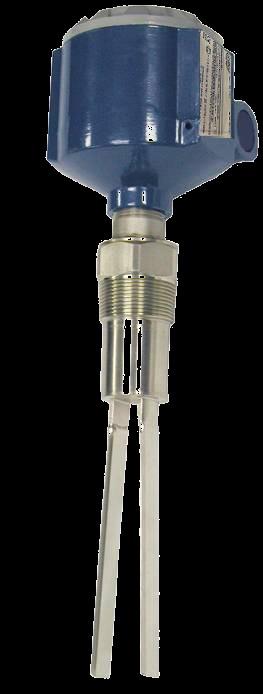
5 2.0 TECHNICAL DATA GENERAL DIMENSIONS 3/4 FNPT CONDUIT ENTRY 4.8 in (121.9 mm) 1-1/2 MNPT 1.66in (42.2mm) 15.6 in (396.2 mm) 9 in (228.6 mm) 1.58 in (40 mm)
6 MECHANICAL DATA Enclosure: Single compartment Cast aluminum Powder coated Vibrating Fork Material: Width Across: Process Connection: 316 stainless steel 1.58 in. (40mm) 1 ½ MNPT Oscillator Material: Surfaced Treatment of Vibrating Rods: Stainless steel Polished Overall Weight GP50 Std: GP50 Ext: Options Flange Connections: Mounting Plate: Approx lbs. (1.6 kg) Approx lbs. (1.6 kg) + about 1.69lbs/ft (2.5 kg/m) extension tube Loose or welded flanges available For Rotary Paddle switch drop in replacement (see page 10) ELECTRICAL DATA Supply Voltage: Installed Load: Electrical Connection: Signal Output: V 50-60Hz V DC universal voltage with relay output. Max. 1 VA (relay) ¾ FNPT Universal voltage with relay-output Floating relay output: Max. AC 253V, 4A, 500W Max. DC 253V, 4A, 60W
7 Switch Status Display: Signal Delay: Safety Operation: Sensitivity: Measuring Frequency: Isolating: Protection Class: By built-in LED Probe free -> covered Approx. 1 sec. Prove covered -> free Approx sec. To be switched over for (FSL, FSH) low / high level fail-to-safe Adjustable to two levels Approx. 125Hz Supply voltage to signal output 3kV~ I OPERATING CONDITIONS Ambient Temperature at the Housing: -13ºF to 140ºF / -25ºC to 60ºC Internal Temperature of the Container: -13ºF to 302º F / -25ºC to 150ºC Min. Powder Density: Features of Bulk Materials: Max. Oscillator Load: Max. Torque: Max. Tensile Force: Max. Container Pressure: Protective Measures in Case of High Loading: Approx. 1.3 pcf (20 g/l) No strong propensity to cake or deposit Max. grain size.40 in (10 mm) Max. 135 ft-lb (600N) laterally (on oscillating rods) 221 ft-lb (300 NM ft-lb (2 Kn) 230 psi (16 bar) Mounting of a protective baffle above the probe
8 Mounting in container with 302ºF/ 150ºC: Maximum ambient temperature at the housing -13ºF to 140ºF Max. 176 F 1.96 in in Max. 176 F 3.0 MOUNTING Max. 302 F Installation of the GP50 in the socket: The socket has to be high enough, so that the maximum surface Temperature at the thread part on the housing is 176 F. Do not place in direct fill path Baffle for high mechanical loading or inlet fill protection Place forks so material flows between tines
9 MP6 Mounting Plate Detail Required for Paddle Switch Replacement 6 holes equally placed on a 7 bolt circle 1.5 FNPT Half Coupling 8.00 Front View Side View Note: For paddle switch replacements, use the SF/MP6 mounting plate for installation. TIPS FOR INSTALLATION Switch Point: Oscillating Fork: Screwing the GP50 In: Agitated/Mixing Applications: Heavy bulk material cover of ~ 1/4 Light bulk material cover of ~ 3/4 Do not bend, shorten or extend the oscillating rods since this will destroy the GP50. Use a 50mm open-end wrench (do not turn the housing). In the case of strong lateral loads, check whether the GP50 could be installed laterally instead of mounting from the top with a long extension piece (GP50 EXT).
10 The Maximum Downward Force on the Fork Assembly Can Be Derived by: Maximum: 88 pounds (40 kg) Formula: Maximum height of material in feet (m) = 2200 (lbs/ft³) Bulk density (kg/m³) Example: If the material weighs 50lbs/ft³ (800.9 kg/m³), the maximum allowable height of material above the fork is = 2200 = 44ft. (13.41m) ELECTRICAL CONNECTIONS SAFETY INSTRUCTIONS Only qualified technical personnel may accomplish installation, maintenance and commissioning. The valid installation instructions must be observed. For terminal connections of the GP50, the local regulations or NEC (National Electrical Code) must be observed. Use a fuse for the supply voltage (max. 4A). Provide protection for relay contacts and output transistors to protect the GP50 against spikes with inductive loads. Compare the supply voltage applied with the specifications given on the electronic module before switching the GP50 on.
11 Make sure that the boots for protecting cable terminations are not longer than.314 in. (danger of contact with live parts). Make sure that the screwed cable gland safely seals the cable and that it is tight (danger of water intrusion). A voltage-disconnecting switch must be provided near the GP50. In the case of a defect, the distribution voltage must automatically be cut off by a FI protective switch so as to protect the user of the GP50 from indirect contact with dangerous electric tensions. In the case of non-ensure handling or handling malpractice, the electric safety of the GP50 cannot be guaranteed. Switch off the supply voltage before opening the GP50. Before opening the lid, take care that no dust deposits or whirlings are present. APPROVALS CE EMV EN61326/A1 Security EN GP50 ELECTRICAL CONNECTIONS
12 5.0 SWITCHING LOGIC Low / High Level Fail-to-Safe If the probe is used to indicate full load: set to maximum-security level FSH LED Signal Power failure or line break is regarded as full signal (protection against overcharging). If the probe is used to indicate empty load: set to minimum-security level FSL Power failure or line break is regarded as empty signal (protection against running dry). Switch FSL / FSH FSL FSH relay output transistor output LED signal relay output transistor output LED signal
13 6.0 ADJUSTMENT / MAINTENANCE ADJUSTMENT Adjustment - Sensitivity All probes have a factory default (factory default = position high ). Therefore, they usually do not have to be readjusted for increased sensitivity. However, if the bulk material has a strong propensity to cake or deposit, the adjustment switch can be set to position low so as to decrease the sensitivity of the probe (Factory default = position high ). Low-High Switch for Sensitivity MAINTENANCE Normally, the GP50 requires no maintenance. However, depending on the individual field of application, the following should be observed and inspected: mechanically damaged oscillating rods coarse cleaning of the oscillating rods
14 Changing the Electronic Module 1. Open the housing lid, remove the pigtails from the GP Disconnect internal wire for earth connection from terminal PE (not at electronic module 2-wire). 3. Unscrew two fastening screws of the electronic module. 4. Pull out electronic module. 5. Insert new electronic module (until it locks into place). 6. Fix internal wire for earth connection to terminal and screw down the fastening screws. 7. Connect the pigtails to the GP50. Internal Earth Connection Fastening Screws (2) Fastening Screws (2)
15 7.0 WARRANTY 5 YEAR WARRANTY FOR: KM26 Magnetic Liquid Level Gauges, Buoyancy Level Switches (LS20, MS50, MS10 & MS8), Magnetic Level Switches (MS30, MS21, MS40, MS41, PS35 & PS45), EC External Chambers and ST95 Seal Pots. 3 YEAR WARRANTY FOR: KCAP300 & KCAP 400 capacitance switches. 2 YEAR WARRANTY FOR: AT100 and AT200 series transmitters; VF20 and VF30 vibrating fork switches; RLT100 and RLT200 reed switch level transmitters; TX, TS, TQ, IX and IM thermal dispersion switches; IR10 and PP10 External Relays; MT2000 radar level transmitters; KP paddle switches; A02, A75 & A77 RF capacitance level switches and A38 RF capacitance level transmitters. 1 YEAR WARRANTY FOR: KM50 gauging device; AT500 and AT600 series transmitters; LaserM and SureShot series laser transmitters; LPM 100 and 200 series digital indicators; DPM100 digital indicators; APM100 analog indicators; KVIEW series digital indicators and controllers; GP50 and SF60 vibrating fork switches, KB Electro-Mechanical Continuous Measuring Devices, KSONIK ultrasonic level switches, transmitters & transducers. SPECIAL WARRANTY CONSIDERATIONS: K-TEK does not honor OEM warranties for items not manufactured by K-TEK (i.e. Palm Pilots). These claims should be handled directly with the OEM. K-TEK will repair or replace, at K-TEK s election, defective items which are returned to K-TEK by the original purchaser within the period specified above from the shipment date of the item and which is found, upon examination by K-TEK, to its satisfaction, to contain defects in materials or workmanship which arose only under normal use and service and which were not the result of either alterations, misuse, abuse, improper or inadequate adjustments, applications or servicing of the product. K-TEK s warranty does not include onsite repair or services. Field service rates can be supplied on request. If a product is believed to be defective, the original purchaser shall notify K-TEK and request a Returned Material Authorization before returning the material to K-TEK, with transportation prepaid by the purchaser. (Request door to door delivery via New Orleans International Airport located in Louisiana, USA.) The product, with repaired or replaced parts, shall be returned to the purchaser at any point in the world with transportation prepaid by K-TEK for best-way transportation only. K-TEK is not responsible for expedited shipping charges. If the product is shipped to K-TEK freight collect, then it will be returned to the customer freight collect. If inspection by K-TEK does not disclose any defects in material or workmanship, K-TEK s normal charges for repair and shipment shall apply (minimum USD). The materials of construction for all K-TEK products are clearly specified and it is the responsibility of the purchaser to determine the compatibility of the materials for the application. THE FOREGOING WARRANTY IS K-TEK'S SOLE WARRANTY AND ALL OTHER WARRANTIES EXPRESSED, IMPLIED, OR STATUTORY, INCLUDING ANY IMPLIED WARRANTY OF MERCHANTABILITY OF FITNESS FOR A PARTICULAR PURPOSE, ARE EXCLUDED AND NEGATED TO THE MAXIMUM EXTENT PERMITTED BY LAW. NO PERSON OR REPRESENTATIVE IS AUTHORIZED TO EXTEND ANY OTHER WARRANTY OR CREATE FOR K-TEK ANY OTHER LIABILITY IN CONNECTION WITH THE SALE OF K-TEK S PRODUCTS. THE REMEDIES SET FORTH IN THIS WARRANTY ARE EXCLUSIVE OF ALL OTHER REMEDIES AGAINST K-TEK. K-TEK SHALL NOT BE LIABLE FOR ANY CONSEQUENTIAL, INCIDENTAL, OR SPECIAL DAMAGES OF ANY KIND. K-TEK S SOLE OBLIGATION SHALL BE TO REPAIR OR REPLACE PARTS (FOUND TO BE DEFECTIVE IN MATERIALS OR WORKMANSHIP) WHICH ARE RETURNED BY THE PURCHASER TO K-TEK.


16
GP50 Vibrating Fork Level Switch. Vibrating level switch for powders and granular solids K-TEK Products
 Operating instruction manual OI/GP50-EN Rev. B GP50 Vibrating Fork Level Switch Vibrating level switch for powders and granular solids K-TEK Products Introduction This operating instruction manual provides
MS40 MS40/EX Explosion
 MS40 MS40/EX Explosion MS40-0200-1 Rev c (10-2010) DCN0530 Table of Contents 1.0 Description..... 3 2.0 Application..3 3.0 Operation.3 4.0 Mounting & Installation 3-4 5.0 Maintenance 4 6.0 Warranty Statement..9
MS Rev c ( ) DCN0530
 DCN0530") MS41-0200-1 Rev c (10-2010) DCN0530 Table of Contents 1.0 Description... 3 2.0 Application... 3 3.0 Operation... 3 4.0 Mounting & Installation... 3-4 5.0 Installation and Wiring... 5 6.0 Warranty Statement...
MS41-0200-1 Rev c (10-2010) DCN0530 Table of Contents 1.0 Description... 3 2.0 Application... 3 3.0 Operation... 3 4.0 Mounting & Installation... 3-4 5.0 Installation and Wiring... 5 6.0 Warranty Statement...
MS40/EX Magnetic Level Gauge Switch. Magnetically actuated 10 amp DPDT electric switch. K-TEK Level products
 Operating instruction manual OI/MS40-EN Rev. D MS40/EX Magnetic Level Gauge Switch Magnetically actuated 10 amp DPDT electric switch K-TEK Level products Introduction This operation and instruction manual
MS41 Magnetic Level Gauge Switch. Magnetically actuated 10 amp hermetically sealed electric switch K-TEK Level products
 Operating instruction manual OI/MS41-EN Rev. D MS41 Magnetic Level Gauge Switch Magnetically actuated 10 amp hermetically sealed electric switch K-TEK Level products Introduction This operation and instruction
LS Series Buoyancy Level Switch. Mechanical Level Switch K-TEK Products
 Operating instruction manual OI/LS-EN Rev. B LS Series Buoyancy Level Switch Mechanical Level Switch K-TEK Products Introduction This operating instruction manual provides the following information: Installation
PS45 Magnetic Level Gauge Switch. Magnetically actuated no-bleed switch K-TEK Products
 Operating instruction manual OI/PS45-EN Rev. C PS45 Magnetic Level Gauge Switch Magnetically actuated no-bleed switch K-TEK Products Introduction This operation and instruction manual provides the following
Installation & Operation Manual RS80/RS85. Vibrating Fork Level Switch. For the latest version of this manual, visit ktekcorp.com.
 Installation & Operation Manual RS80/RS85 RS80 RS85 For the latest version of this manual, visit ktekcorp.com. Table of Contents 1.0 Introduction... 3 1.1 Description... 3 1.2 Theory of Operation... 3
Kondunivo Table of contents
 Kondunivo Table of contents Page Introduction G Technical data G Mounting G Electrical connection G Adjustment G Switching logic G Maintenance G Error search G Subject to technical change and price change.
KP Specialty Level Instruments. Rotary Paddle Switch K-TEK Products
 Operating instruction manual OI/KP-EN Rev. G 04.2013 KP Specialty Level Instruments Rotary Paddle Switch K-TEK Products Introduction This operating instruction manual provides the following information:
DIAMOND POINT VIBRATING PROBES
 DIAMOND POINT VIBRATING PROBES DP130 DP120 DP140 DP150 Instruction Manual Third revision, April 2016 Hycontrol Ltd., Larchwood House, Orchard Street, Redditch, Worcestershire, B98 7DP, U.K. Tel: + 44 (0)1527
 Table of contents Page Safety notes / Technical support Introduction Technical data Approvals Options Mounting Electrical installation 1 Signal output 1 Sensitivity setting 1 Maintenance 1 Notes for use
 Table of contents Page Safety notes/ Technical support Introduction Technical data Approvals Options/ accessories Mounting Electrical installation 1 Settings 1 Signal output logic 1 Maintenance 1 Notes
CVR-625. Compact Vibrating Rod Instruction Manual
 CVR-625 Compact Vibrating Rod Instruction Manual BinMaster: Division of Garner Industries 7201 N. 98th St., Lincoln, NE 68507 402-434-9102 email: info@binmaster.com www.binmaster.com OPERATING INSTRUCTIONS
P U L S A R point 210
 P U L S A R point 210 Page 2 Fourth Edition - Version 1.0 Jan 2014 Copyright Copyright PULSAR Process Measurement Limited 2014. All rights reserved. No part of this publication may be reproduced, transmitted,
CBC-802 Plug-In Clutch/Brake Control with Solid State Switching
 DIST. AUTORIZADO Plug-In Clutch/Brake Control with Solid State Switching P-29-5 19-0409 Service & Installation Instructions An Altra Industrial Motion Company DIST. AUTORIZADO Brake (Red) and clutch (Green)
CBC-160-1N and CBC-160-2N Clutch/Brake Controls
 P-239-36 819-04 CBC-160-1N and Clutch/Brake Controls Installation Instructions An Altra Industrial Motion Company Contents Introduction...2 Specifications........................... 2 Installation...3
CBC-300 Series & CBC-300C Series Dual Channel Adjust Clutch/Brake Controls
 CBC-300 Series & CBC-300C Series Dual Channel Adjust Clutch/Brake Controls P-269-89-0408 Installation Installation & Operating Instructions Contents Introduction........................... 2 Specifications.........................
BMRX Series ROTARY LEVEL CONTROL
 BMRX Series ROTARY LEVEL CONTROL OPERATING INSTRUCTIONS PLEASE READ CAREFULLY 925-0292 Rev C TABLE OF CONTENTS GENERAL SPECIFICATIONS... 3 SAFETY SUMMARY... 4 1.0 INTRODUCTION... 5 2.0 INSTALLATION...
Capanivo Series CN 4000
 Capanivo Series CN 4000 Instruction manual 010516 1 UWT GmbH Westendstraße 5 Tel.: +49 (0)831 57123-0 Internet:www.uwt.de D-87488 Betzigau Fax: +49 (0)831 76879 E-Mail: info@uwt.de Scope of this instruction
Operating instructions According to Directive 2014/34/EU (ATEX) Annex II p group II, equipment category 1/2D
 Annex II p group II, equipment category 1/2D") 1. Introduction Fig.1 MAX. ( Process ) MIN. ( Ambient ) The Rotative Level Control RL-A AD1/2* are used to detect the level of materials such as dust or granules in containers. They are supplied with plastic
1. Introduction Fig.1 MAX. ( Process ) MIN. ( Ambient ) The Rotative Level Control RL-A AD1/2* are used to detect the level of materials such as dust or granules in containers. They are supplied with plastic
CBC-300 & CBC Series Dual Channel Adjust Clutch/Brake Controls
 CBC-300 & CBC-300- Series Dual Channel Adjust Clutch/Brake Controls P-205-WE 89-0549 Installation & Operating Instructions An Altra Industrial Motion Company Contents Introduction... 2 Specifications...
CBC-802 Plug-In Clutch/Brake Control with Solid State Switching
 CBC-02 Plug-In Clutch/Brake Control with Solid State Switching P-2104-WE 19-054 Service & Installation Instructions An Altra Industrial Motion Company Brake (Red) and clutch (Green) indicator lights When
STOCKTROL-H VIBRATING LEVEL SWITCH. Instruction Manual June 2002
 STOCKTROL-H VIBRATING LEVEL SWITCH Instruction Manual June 2002 Safety Guidelines Warning notices must be observed to ensure personal safety as well as that of others, and to protect the product and the
GRINNELL Model B302 and Model BN302 Grooved End Butterfly Valves with Gear Operators or Lever-Lock Operators General Description
 Technical Services -00- +-0--0 www.grinnell.com GRINNELL Model B0 and Model BN0 Grooved End Butterfly Valves with Gear Operators or Lever-Lock Operators General Description The GRINNELL Models B0 and BN0
NEO-DYN MODEL 100P ENCLOSURE 7 ADJUSTABLE EXPLOSION-PROOF PRESSURE SWITCH
 NEO-DYN MODEL 100P ENCLOSURE 7 ADJUSTABLE EXPLOSION-PROOF PRESSURE SWITCH INSTALLATION AND OPERATION MANUAL PN 610-0006 Rev E WARNING CAUTION SPECIAL CONDITIONS FOR SAFE USE NOTE Manual No. 610-0006 Rev
Switch Pro w/ Compact Junction Box A_1_ Series Owner s Manual
 Warranty, Service & Repair To register your product with the manufacturer, go to the Flowline website for on-line registration. The website address is as follows: www.flowline.com On-line Warranty Registration
Electric Actuator Installation, Operation & Maintenance Manual
 ICI Indelac Controls, Inc. Electric Actuator Installation, Operation & Maintenance Manual 6810 Powerline dr.-florence, Ky. 41042 - Telephone 859-727-7890, Tool free 800-662-9424 Fax. 859-727-4070, e-mail:
Level limit switch Series RF 3000 Selection list
 Table of content Page Overview P2 Applications P4 ------------------------------------------------------------------------------------------------------------- RF 3100 Standard version P6 -------------------------------------------------------------------------------------------------------------
 Table of contents Series VN 00 / 000 / 000 / 000 Page Safety notes / Technical support G --------------------------------------------------------------------------------------------------------- Introduction
LU27 Series Quick Start
 Ultrasonic Liquid Level Transmitter LU27 Series Quick Start 2016 Flowline, Inc. All Rights Reserved Made in USA Flowline, Inc. 10500 Humbolt Street, Los Alamitos, CA 90720 p 562.598.3015 f 562.431.8507
PVI 1800/PVI Residential/Commercial Grid-Tied Photovoltaic Inverter WARRANTY MANUAL. Subject to Change REV , Solectria Renewables
 PVI 1800/PVI 2500 WARRANTY MANUAL Residential/Commercial Grid-Tied Photovoltaic Inverter 2009, Solectria Renewables Subject to Change REV 10.09 1 Product Warranty & RMA Policy 1.1 Warranty Policy The Solectria
Warner Electric UNIBRAKE Motor Brakes
 P-1699-WE Warner Electric UNIBRAKE Motor Brakes Installation & Operating Instructions Double C Contents General Information........................ 2 Brake Heads............................. 2 Installation...............................
Soliphant T FTM260. Technical Information. Level limit switch Cost-effective vibration limit switch for fine-grained solids
 Technical Information Soliphant T FTM260 Level limit switch Cost-effective vibration limit switch for fine-grained solids Application Soliphant is a rugged level limit switch for use in silos containing
INSTALLATION AND OPERATING MANUAL
 Publication T3-76, Rev. 1 Dated: May 9, 21 INSTALLATION AND OPERATING MANUAL MODEL: T3-I TURBOTWIN Engine Air Starter AN96-419 From Tech Development Inc 68 Poe Ave. Dayton OH 45414 Tel: (937) 898-96 Fax:
MAIN FUNCTION FEATURES. . D = v t /2
 INTRODUCTION The ultrasonic level Indicator is a low-cost, noncontact and easy-to-install measurement device. It is able to meet the every-day needs of commercial production, as well serving a more specialized
PROCAP Capacitance Level Sensors
 PROCAP Capacitance Simple. Rugged. Reliable. Triple thread screw on/off cover - No more bolts! Unsurpassed sensitivity and stability No interference from RF signals Switch selectable high/low fail-safe
OPERATING INSTRUCTIONS PLEASE READ CAREFULLY
 OPERATING INSTRUCTIONS PLEASE READ CAREFULLY 925-0330 Rev 0 0416 TABLE OF CONTENTS SAFETY SUMMARY... 3 SPECIFICATIONS... 4 1.0 INTRODUCTION/DESCRIPTION.... 5 2.0 LOCATION AND MOUNTING... 5 3.0 CONNECTIONS
ProFlo FatBoy
 The Standard For Professional Grade Diaphragm Pumps. ProFlo 3300 5500 FatBoy Operational and Installation Guidelines, Repair & Parts Contents 3300 5500 Fatboy Operational and Installation Guidelines...2
LED LARGE WALL PACK (CUTOFF & STANDARD)
") General Safety Information To reduce the risk of death, personal injury or property damage from fire, electric shock, falling parts, cuts/abrasions, and other hazards read all warnings and instructions
General Safety Information To reduce the risk of death, personal injury or property damage from fire, electric shock, falling parts, cuts/abrasions, and other hazards read all warnings and instructions
Digital echo-charge. Owner s Manual. Xantrex Digital echo-charge Battery Charger
 Digital echo-charge Owner s Manual Xantrex Digital echo-charge Battery Charger INTRODUCTION The Xantrex Digital echo-charge is specially developed for charging an auxiliary battery with Freedom TM or Fleet
VP-4124/VP-4124-E 24/48 VOLT DC SWITCHING POWER SUPPLY
 Issue 5 24/48 VOLT DC SWITCHING POWER SUPPLY INTRODUCTION These instructions provide the specifications, installation and maintenance information for the VP-4124 and VP-4124-E, 24/48 Volt Power Supplies.
BC Brake Caliper. (i) MEX (55) QRO (442) MTY (81) DIST. AUTORIZADO
 MEX (55) QRO (442) MTY (81) DIST. AUTORIZADO") MEX (55) 5 6 QRO (44) 95 7 60 MTY () 54 0 BC Brake Caliper (i) FORM NO. L-0066-B-040 In accordance with Nexen s established policy of constant product improvement, the specifications contained in this
MEX (55) 5 6 QRO (44) 95 7 60 MTY () 54 0 BC Brake Caliper (i) FORM NO. L-0066-B-040 In accordance with Nexen s established policy of constant product improvement, the specifications contained in this
Level limit switch Series CN 4000 Selection list. Specifications 2. Applications 4
 Table of contents Page Specifications 2 Applications 4 ------------------------------------------------------------------------------------------------------------ CN 4020 5 Short extension length ------------------------------------------------------------------------------------------------------------
LU23, LU28 & LU29 Series Quick Start
 Ultrasonic Liquid Level Transmitter LU23, LU28 & LU29 Series Quick Start 2016 Flowline, Inc. All Rights Reserved Made in USA Flowline, Inc. 10500 Humbolt Street, Los Alamitos, CA 90720 p 562.598.3015 f
INSTALLATION & OPERATING INSTRUCTIONS: REVOLUTION SPINEBOARD ATTACHMENT WARNING
 INSTALLATION & OPERATING INSTRUCTIONS: REVOLUTION SPINEBOARD ATTACHMENT LOAD CAPACITY: 500 LBS [227 kg] MANDATORY: LEAVE THIS MANUAL WITH LIFT OWNER WARNING 1. READ AND FOLLOW ALL INSTRUCTIONS. LIFT SAFETY
TPHK Series Immersible Pump
 TPHK Series Immersible Pump Instruction Manual ISO 9001 Certified Walrus America Inc 234867 EC Declaration of Conformity Manufacturer: Walrus Pump Co., Ltd. Address: No. 83-14, Dapiantou, Sanjhih Township,
Broadband PowerShield. CP27U Models. User Manual
 Broadband PowerShield CP27U Models User Manual 990-2366C 04/2016 Chapter 1: General Information The PowerShield provides a power source for broadband telephony, Fiber-to-the-Home/Premise (FTTH/P), and
ERD Electrically Released Brakes
 ERD Electrically Released Brakes P-229 819-0453 Installation Instructions Warner Electric s ERD series spring set, electrically released brakes are designed to hold a load when the power to the brake is
LMG100 Econolev Magnetic level gauge KTEK products. Measurement made easy
 Operation instruction manual OI/LMG100-EN LMG100 Econolev Magnetic level gauge KTEK products Measurement made easy Introduction ABB offers the standard LMG100 Econolev Magnetic Level Gauge with a 316 stainless
Switch-Pak. AU13, AV13 & AZ13 Series Owner s Manual. w/ Compact Relay Controller
 Switch-Pak w/ Compact Relay Controller AU13, AV13 & AZ13 Series Owner s Manual Flowline, Inc.. 10500 Humbolt Street, Los Alamitos, CA 90720. p 562.598.3015. f 562.431.8507. w flowline.com MN301430 Rev
HA/HAB Fiberglass Wall Mount Ventilators
 HA/HAB Fiberglass Wall Mount Ventilators INSTALLATION, OPERATION & MAINTENANCE MANUAL IM-3100 August 2015 Throughout this manual, there are a number of HAZARD S that must be read and adhered to in order
OPERATION MANUAL Variable Speed Pump Controller Dated: 06/04/2013 Pump Down Application. Document No.: LMSII_V100_OM Page 1 of 8 Model-V100 LMS II
 Document No.: LMSII_V100_OM Page 1 of 8 LMS II Document No.: LMSII_V100_OM Page 2 of 8 1. Operation: When the wet well level rises above the on level set point, the lead pump will start after an adjustable
Installation and Operating Manual
 MOTORS AND DRIVES SIGNAL ISOLATOR Accessory for BC204 Regenerative Drive Installation and Operating Manual 4/2000 MN1387 TABLE OF CONTENTS Section Page i. Safety Warning..........................................................
CRICKET Alphasonic Level Transmitter Model LA12 Owner s Manual
 Warranty, Service and Repair To register your product with the manufacturer, fill out the enclosed warranty card and return it immediately to: FLOWLINE Inc. 10500 Humbolt Street Los Alamitos, CA 90720
Flo-Way. Measure Granular or Powdered Material. Stand Alone or Connect to Other Devices for Blending. Used by Successful Producers World-Wide
 Flo-Way R Solids Impact Flow Meter Measure Granular or Powdered Material Stand Alone or Connect to Other Devices for Blending Used by Successful Producers World-Wide Visit our website: www.beltwayscales.com
Models DP10 & DP20 Series Low Voltage Disconnects User s Manual Rev. 1.1 October 31, 2007
 B R A N D Models DP10 & DP20 Series Low Voltage Disconnects User s Manual Rev. 1.1 October 31, 2007 For Sales, Support and Service phone: 407-331-4793 fax: 407-331-4708 website: www.xenotronix.com email:
Elgin Hydraulic Clutch-Brake ECB-240, Product Number FORM NO. L F FORM NO. L F-0704
 Elgin Hydraulic Clutch-Brake ECB-20, Product Number 96225 FORM NO. L-20283-F-070 1 FORM NO. L-20283-F-070 In accordance with Nexen s established policy of constant product improvement, the specifications
MaxLite LED UTILITY WRAP FIXTURES
 General Safety Information To reduce the risk of death, personal injury or property damage from fire, electric shock, falling parts, cuts/abrasions, and other hazards read all warnings and instructions
Switch-Tek Horizontal and Vertical And Float-Point Float Switches LV20, LV21, LV35, LV36, LH25, LH29, LH35, AV_6 Series 22AUG 08 Rev A
 Switch-Tek Horizontal and Vertical And Float-Point Float Switches LV20, LV21, LV35, LV36, LH25, LH29, LH35, AV_6 Series 22AUG 08 Flowline, Inc. 10500 Humbolt Street Los Alamitos, CA 90720 Tel: (562) 598-3015
model ps600 Address all communications and shipments to: FEDERAL SIGNAL CORPORATION
 MODEL: PS600 HZ: 60 A model ps600 installation and service manual for federal model ps600 FEDERAL SIGNAL CORPORATION POWER SUPPLY VOLTS: SERIES: 120VAC FEDERAL SIGNAL CORPORATION UNIVERSITY PARK, IL. U.S.A.
 OPERATING MANUAL: L/S VARIABLE-SPEED MODULAR DRIVES Model Nos. Pump Drive 07559-00 with Pump Head 07516-00 07559-00 07559-05 07559-10 07559-15 A-1299-7331 Edition 01 (US & Canada only) Toll Free 1-800-MASTERFLEX
PVI 60KW, PVI 82KW, PVI 95KW
 PVI 60KW PVI 82KW PVI 95KW WARRANTY MANUAL Commercial, Grid-Tied Photovoltaic Inverters 2008, Solectria Renewables LLC Subject to Change DOC-020099 rev 024 1 1 Product Warranty & RMA Policy Warranty Policy
FCB-450, LCB-600, MCB-800
 AIR CHAMP PRODUCTS User Manual FCB-450, LCB-600, MCB-800 Clutch-Brakes (i) In accordance with Nexen s established policy of constant product improvement, the specifications contained in this manual are
MANUAL Model: PT 12/24-60 Solar Converters Inc. - Rev. F
 1.0 Specification MANUAL Model: PT 12/24-60 Solar Converters Inc. - Rev. F Note: This unit is a Multi - Voltage unit with adjustable input panel and output battery adjustment. Please review the section
CM3000 SIGNAL TRANSMITTER. Introduction. The MAXIGARD CM3000 is designed to convert shaft speed into a 4/20 ma or 0-10 VDC analog output signal.
 CM228-03, Page 1 952-935-4201, INC. (Fax) 952-935-9628 3947 MEADOWBROOK ROAD, MINNEAPOLIS, MN 55426 800-328-0738 CM3000 SIGNAL TRANSMITTER Introduction The MAXIGARD CM3000 is designed to convert shaft
Super-Safe-Plus Roto-Bin-Dicator
 Super-Safe-Plus Roto-Bin-Dicator for your most demanding applications... Offers both mechanical and electronic sensing in one reliable Point Level Sensor... Level control with added confidence Under normal
NIVOCONT R VIBRATING ROD LEVEL SWITCHES
 For solids NIVOCONT R VIBRATING ROD LEVEL SWITCHES O U R P R O F E S S I O N I S Y O U R L E V E L LEVEL SWITCHES O U R P R O F E S S NIVOCONT R VIBRATING ROD LEVEL SWITCHES MAIN FEATURES Extension up
>:RTS1V0Cmanual (C) ISS INSTALLATION INSTRUCTIONS
 ISS INSTALLATION INSTRUCTIONS") 1. EXCLUSIVE WRITTEN LIMITED WARRANTY WARRANTY INFORMATION ALL PRODUCTS SOLD ARE WARRANTED BY THE COMPANY (4B COMPONENTS LIMITED, (4B) BRAIME ELEVATOR COMPONENTS LIMITED, AND (4B) S.E.T.E.M. Sarl) HEREIN
1. EXCLUSIVE WRITTEN LIMITED WARRANTY WARRANTY INFORMATION ALL PRODUCTS SOLD ARE WARRANTED BY THE COMPANY (4B COMPONENTS LIMITED, (4B) BRAIME ELEVATOR COMPONENTS LIMITED, AND (4B) S.E.T.E.M. Sarl) HEREIN
WATERBLAST HOSE REEL SYSTEM HWB HOSE REEL OPERATION AND MAINTENANCE MANUAL W A T E R J E T T O O L S
 WATERBLAST HOSE REEL SYSTEM HWB HOSE REEL OPERATION AND MAINTENANCE MANUAL W A T E R J E T T O O L S 466 S. SKYLANE DR. DURANGO, COLORADO 81303 970-259-2869 PHONE 970-259-2868 FAX www.stoneagetools.com
RESOURCE GUIDE. P r o d u c t M a n u a l. START International
 RESOURCE GUIDE P r o d u c t M a n u a l The information contained in this Resource Guide along with additional maintenance and repair information, videos and photos can be found online at www.startinternational.com
VFL-280. Visible Fault Locator. Operating Manual
 VFL-280 Visible Fault Locator Operating Manual Terahertz Technologies Inc. 169 Clear Road Oriskany, New York 13424 TEL: (315) 736-3642 7/2011 Table of Contents Introduction...1 Unpacking and Inspection...1
INSTALLATION AND OPERATING MANUAL
 Dated: May 10, 2001 INSTALLATION AND OPERATING MANUAL MODEL: T30-Y TURBOTWIN Engine Air Starter From Tech Development Inc AN96-425 6800 Poe Ave. Dayton OH 45414 Tel: (937) 898-9600 Fax: (937) 898-8431
INSTRUCTION MANUAL INSTALLATION, OPERATION, AND MAINTENANCE ACTUATOR MANIFOLD
 INSTRUCTION MANUAL INSTALLATION, OPERATION, AND MAINTENANCE B-3724M ACTUATOR MANIFOLD MIDLAND MANUFACTURING CORP. 7733 Gross Point Road Skokie, Illinois 60077 Phone (847) 677-0333 FAX (847) 677-0138 WEBSITE
Nor East. Instructions Safety Messages. Inspection. Parts. DeZURIK Service. Type 05 Pneumatic Actuator Used With Globe Valves
 Instructions Safety Messages These instructions are intended for personnel who are responsible for installation, operation and maintenance of your DeZURIK Actuator. All safety messages in the instructions
DAP-625S and DAP-875S
 AIR CHAMP PRODUCTS DAP-625S and DAP-875S (i) FORM NO. L-20078-B-0501 In accordance with Nexen s established policy of constant product improvement, the specifications contained in this manual are subject
PVC Gasketed Fittings for PVC IPS Pressure Pipe ENGINEERED FOR DURABILITY
 For the most up-to-date version of this price list, EFFECTIVE MARCH 4, 2019 ENGINEERED FOR DURABILITY HARRINGTON CORPORATION P.O. BOX 10335 LYNCHBURG, VIRGINIA 24506-0335 For the most up-to-date version
PRYCO, INC. P. O. BOX 108 Mechanicsburg, IL OPERATIONS AND MAINTENANCE MANUAL For PUMP SETS
 PRYCO, INC. P. O. BOX 108 Mechanicsburg, IL 62545 Telephone: 217 / 364-4467 Fax: 217 / 364-4494 OPERATIONS AND MAINTENANCE MANUAL For PUMP SETS WHAT TO DO FIRST Upon receiving your new pump set system
Installation & Operation Manual. Electrak 100 Series / Electromechanical Linear Actuator
 www..c Installation & Operation Manual Electrak 100 Series / Electromechanical Linear Actuator Thomson has many years of experience designing and manufacturing linear actuators for a wide variety of applications
Effective June 1, 2013 This guide supersedes all previous versions
 Effective June 1, 2013 This guide supersedes all previous versions 3842 Redman Drive 1-800-797-7974 Fort Collins, CO 80524 www.commandlight.com L-CAS THANK YOU Please allow us to express a simple thank
PSC-301 Pump Stroke Counter
 PSC-301 Pump Stroke Counter 3 PUMP MODEL Operations and Maintenance Manual Rev 1000 WG Industries, Inc. 2825 Creek Bend Drive Friendswood, TX 77546 Ph 713 416 1585 Fax 281 404 9054 Toll Free 800 440 1153
Heavy Duty Industrial Foot Switches
 P-1303 819-0523 Heavy Duty Industrial Foot Switches Installation Instructions Failure to follow these instructions may result in product damage, equipment damage, and serious or fatal injury to personnel.
Metrohm E3640 FLASH TESTER INSTRUCTION MANUAL. Martindale Electric Co Ltd.
 Metrohm Martindale Electric Metrohm House, Imperial Park, Imperial Way, Watford, Hertfordshire, WD24 4PP, UK T: 01923 441717 F: 01923 446900 Email: sales@martindale-electric.co.uk web: www.martindale-electric.co.uk
Vibrating Level Switches for Liquids & Solids HYC-VLS02 Elect. Iss. 02 SIL 2 APPROVED VIBRATING LEVEL SWITCHES FOR LIQUIDS AND SOLIDS
 Vibrating Level Switches for Liquids & Solids HYC-VLS02 Elect. Iss. 02 SIL 2 APPROVED VIBRATING LEVEL SWITCHES FOR LIQUIDS AND SOLIDS VIBRATING PROBE LEVEL SWITCHES FOR LIQUIDS AND SOLIDS PRINCIPLE OF
Illustrations on the manual are for installation purposes only. It may not be identical to the fixture purchased.
 General Safety Information To reduce the risk of death, personal injury or property damage from fire, electric shock, falling parts, cuts/abrasions, and other hazards read all warnings and instructions
WARRANTY POLICY. Grid-Tied Photovoltaic Inverters. Revision D. 2014, Solectria Renewables, LLC DOCIN
 WARRANTY POLICY Revision D 2014, Solectria Renewables, LLC DOCIN-070360 1 Product Warranty & RMA Policy 1. Warranty Policy Warranty Registration: It is important to have updated information about the inverter
60 PSI Boost Gauge. For Product Numbers: MT-DV01_60, MT-WDV01_60
 60 PSI Boost Gauge For Product Numbers: MT-DV01_60, MT-WDV01_60 Red: 12v Constant (un-switched) Source (+) Orange: 12v Dimmer (switched) Source (+) (optional) White: 12v Ignition (switched) Source (+)
Electromagnetic Particle Brakes Model: PRB-H
 P-223-3 819-0370 Electromagnetic Particle Brakes Model: PRB-H Installation Instructions Table of Contents Introduction............................2 Installation Instructions....................3 Start
Straight-Bore Clutch LSCC-32, 44, 54
 Straight-Bore Clutch LSCC-32, 44, 54 1 In accordance with Nexen s established policy of constant product improvement, the specifications contained in this manual are subject to change without notice. Technical
XP88 & XP89 Series Quick Start
 Ultrasonic Liquid Level Transmitter XP88 & XP89 Series Quick Start 2016 Flowline, Inc. All Rights Reserved Made in USA Flowline, Inc. 10500 Humbolt Street, Los Alamitos, CA 90720 p 562.598.3015 f 562.431.8507
Installation Guide. Spring Steer Suspensions. Air-Weigh Customer Support: Welded Steer Brackets PN R0
 Installation Guide Spring Steer Suspensions Welded Steer Brackets Air-Weigh Customer Support: 888-459-3247 PN 901-0146-003 R0 1 Table of Contents Overview...1 Tools Required...1 Installing the Sensor Bracket...2
Smart Trak. AU18, AU28, AU38, AU48, AV16, AV26, AV36, AV46, AZ18, AZ28, AZ38 & AZ48 Series Owner s Manual. w/ Compact Junction Box
 Smart Trak w/ Compact Junction Box AU18, AU28, AU38, AU48, AV16, AV26, AV36, AV46, AZ18, AZ28, AZ38 & AZ48 Series Owner s Manual Flowline, Inc.. 10500 Humbolt Street, Los Alamitos, CA 90720. p 562.598.3015.
RS85 Vibrating fork level switch
 Data sheet DS/-EN Rev. P Multi-option liquid level switch K-TEK Level products Measurement made easy Features Direct replacement for ultrasonic Gap switches, RF capacitance switches, float switches and
EchoPod. UG06 & UG12 Series Quick Start Flowline, Inc. All Rights Reserved Made in USA. Ultrasonic Liquid Level Transmitter
 EchoPod Ultrasonic Liquid Level Transmitter UG06 & UG12 Series Quick Start 2017 Flowline, Inc. All Rights Reserved Made in USA Flowline, Inc. 10500 Humbolt Street, Los Alamitos, CA 90720 p 562.598.3015
QSB (Q-Star) Electronics for QSE Electromagnetic Meter. Owner s Manual TABLE OF CONTENTS
 Electronics for QSE Electromagnetic Meter. Owner s Manual TABLE OF CONTENTS") Owner s Manual QSB (Q-Star) Electronics for QSE Electromagnetic Meter Plain Cover Plate and Pulse-Out Transmitter (QSB) Display Mount Cover Plate (to mount a Q09 Display) and Pulse-Out Transmitter (QSB)
Owner s Manual QSB (Q-Star) Electronics for QSE Electromagnetic Meter Plain Cover Plate and Pulse-Out Transmitter (QSB) Display Mount Cover Plate (to mount a Q09 Display) and Pulse-Out Transmitter (QSB)
Through-Shaft Clutch-Brake LSCB-32HT, LSCB-32HT, LSCB-44, LSCB-44HT, LSCB-54HT FORM NO. L D-0606 MEX (55) QRO (442)
 QRO (442)") Through-Shaft Clutch-Brake LSCB-HT, LSCB-HT, LSCB-, LSCB-HT, LSCB-5HT In accordance with Nexen s established policy of constant product improvement, the specifications contained in this manual are subject
Through-Shaft Clutch-Brake LSCB-HT, LSCB-HT, LSCB-, LSCB-HT, LSCB-5HT In accordance with Nexen s established policy of constant product improvement, the specifications contained in this manual are subject
Grundfos Variable Speed GRUNDFOS INSTRUCTIONS. Installation and Operation
 GRUNDFOS INSTRUCTIONS Grundfos Variable Speed Installation and Operation Pumps Incorporating the (VS) Variable Speed Control with Date Code 0838 or higher 1. 2. 3. 4. Shipment Inspection General Features
INSTRUCTION MANUAL. Rotary Unidirectional Piezoelectric Motor Evaluation Kit. (Model: UPM-28) Made in USA
 Made in USA") www.dtimotors.com INSTRUCTION MANUAL Rotary Unidirectional Piezoelectric Motor Evaluation Kit (Model: UPM-28) Made in USA Rev. 6/2/2017 Table of Contents 1.0 Introduction... 2 2.0 Properties... 3 3.0 Unpacking
www.dtimotors.com INSTRUCTION MANUAL Rotary Unidirectional Piezoelectric Motor Evaluation Kit (Model: UPM-28) Made in USA Rev. 6/2/2017 Table of Contents 1.0 Introduction... 2 2.0 Properties... 3 3.0 Unpacking
TBM Series 3-Way Ball Valve
 www.simtechusa.com TBM Series 3-Way Ball Valve Operating, Installation, & Maintenance Manual Corrosion Resistant Fluid and Air Handling Systems. Dated 06-26-13 TBM Series Ball Valves SIMTECHRECOMMENDSREADINGTHEFOLLOWINGINFORMATIONPRIORTOINSTALLINGANDUSING
Level Devices. Rotary Level Indicators Roto-Bin-Dicator
 7901 NW 107th Terrace Level Devices We offer Rotary Level Indicators, Radio Frequency Level Indicators, and Turning Fork Level Sensors. For more information please contact your Schenck Process Aftermarket