California Proposition 65 WARNING
|
|
|
- Camron Benedict Hensley
- 5 years ago
- Views:
Transcription
1 California Proposition 65 WARNING Engine exhaust, some of its constituents, certain vehicle components and fluids, contain or emit chemicals known to the State of California to cause cancer and birth defects or other reproductive harm.

2 1J

3 FOREWORD You are now the proud owner of a KUBOTA Engine. This engine is a product of KUBOTA quality engineering and manufacturing. It is made of fine materials and under a rigid quality control system. It will give you long, satisfactory service. To obtain the best use of your engine, please read this manual carefully. It will help you become familiar with the operation of the engine and contains many helpful hints about engine maintenance. It is KUBOTA's policy to utilize as quickly as possible every advance in our research. The immediate use of new techniques in the manufacture of products may cause some small parts of this manual to be outdated. KUBOTA distributors and dealers will have the most up-to-date information. Please do not hesitate to consult with them. SAFETY FIRST This symbol, the industry's "Safety Alert Symbol", is used throughout this manual and on labels on the machine itself to warn of the possibility of personal injury. Read these instructions carefully. It is essential that you read the instructions and safety regulations before you attempt to assemble or use this unit. DANGER : WARNING : CAUTION : IMPORTANT : NOTE : Indicates an imminently hazardous situation which, if not avoided, will result in death or serious injury. Indicates a potentially hazardous situation which, if not avoided, could result in death or serious injury. Indicates a potentially hazardous situation which, if not avoided, may result in minor or moderate injury. Indicates that equipment or property damage could result if instructions are not followed. Gives helpful information.
4 CONTENTS SAFE OPERATION...1 SERVICING OF THE ENGINE...1 NAMES OF PARTS...2 PRE-OPERATION CHECK...3 BREAK-IN...3 DAILY CHECK...3 OPERATING THE ENGINE...4 STARTING THE ENGINE(NORMAL)...4 COLD WEATHER STARTING...5 STOPPING THE ENGINE...6 CHECKS DURING OPERATION...6 Radiator Cooling water(coolant)... 6 Oil pressure lamp... 6 Fuel... 7 Color of exhaust... 7 Immediately stop the engine if;... 7 REVERSED ENGINE REVOLUTION AND REMEDIES...7 How to tell when the engine starts running backwards... 7 Remedies... 7 MAINTENANCE...8 SERVICE INTERVALS...9 PERIODIC SERVICE...12 FUEL...12 Fuel level check and refueling Air bleeding the fuel system Checking the fuel pipes Cleaning the fuel filter pot Fuel filter cartridge replacement ENGINE OIL...15 Checking oil level and adding engine oil Changing engine oil Replacing the oil filter cartridge RADIATOR...17 Checking coolant level, adding coolant Changing coolant Remedies for quick decrease of coolant Checking radiator hoses and clamp bands Precaution at overheating Cleaning radiator core (outside) Cleaning the radiator (inside) Anti-freeze AIR CLEANER...21 Evacuator valve For the air cleaner with a dust cup (optional) Dust indicator (optional) ELECTRIC WIRING...22 FAN BELT...22
5 CONTENTS Adjusting Fan Belt Tension CARRIAGE AND STORAGE...23 CARRIAGE...23 STORAGE...23 TROUBLESHOOTING...24 SPECIFICATIONS...26 WIRING DIAGRAMS...32


6 SAFE OPERATION SAFE OPERATION Careful operation is your best assurance against an accident. Read and understand this section carefully before operating the engine. All operators, no matter how much experience they may have, should read this and other related manuals before operating the engine or any equipment attached to it. It is the owner's obligation to provide all operators with this information and instruct them on safe operation. Be sure to observe the following for safe operation. 1. OBSERVE SAFETY INSTRUCTIONS A Read and understand carefully this "OPERATOR'S MANUAL" and "LABELS ON THE ENGINE" before attempting to start and operate the engine. A Learn how to operate and work safely. Know your equipment and its limitations. Always keep the engine in good condition. A Before allowing other people to use your engine, explain how to operate and have them read this manual before operation. A DO NOT modify the engine. UNAUTHORIZED MODIFICATIONS to the engine may impair the function and/or safety and affect engine life. If the engine does not perform properly, consult your local Kubota Engine Distributor first WEAR SAFE CLOTHING AND PERSONAL PROTECTIVE EQUIPMENT (PPE) A DO NOT wear loose, torn or bulky clothing around the machine that may catch on working controls and projections or into fans, pulleys and other moving parts causing personal injury. A Use additional safety items-ppe, e.g. hard hat, safety protection, safety goggles, gloves, etc., as appropriate or required. A DO NOT operate the machine or any equipment attached to it while under the influence of alcohol, medication, or other drugs, or while fatigued. A DO NOT wear radio or music headphones while operating the engine.
7 2 SAFE OPERATION 3. CHECK BEFORE STARTING & OPERATING THE ENGINE A Be sure to inspect the engine before operation. Do not operate the engine if there is something wrong with it. Repair it immediately. A Ensure all guards and shields are in place before operating the engine. Replace any that are damaged or missing. A Check to see that you and others are a safe distance from the engine before starting. A Always keep the engine at least 3 feet (1 meter) away from buildings and other facilities. A DO NOT allow children or livestock to approach the machine while the engine is running. A DO NOT start the engine by shorting across starter terminals. The machine may start in gear and move. Do not bypass or defeat any safety devices. 4. KEEP THE ENGINE AND SURROUNDINGS CLEAN A Be sure to stop the engine before cleaning. A Keep the engine clean and free of accumulated dirt, grease and trash to avoid a fire. Store flammable fluids in proper containers and cabinets away from sparks and heat. A Check for and repair leaks immediately. A DO NOT stop the engine without idling; Allow the engine to cool down, first. Keep the engine idling for about 5 minutes before stopping unless there is a safety problem that requires immediate shut down. 5. SAFE HANDLING OF FUEL AND LUBRICANTS -KEEP AWAY FROM FIRE A Always stop the engine before refueling and/or lubricating. A DO NOT smoke or allow flames or sparks in your work area. Fuel is extremely flammable and explosive under certain conditions. A Refuel at a well ventilated and open place. When fuel and/or lubricants are spilled, refuel after letting the engine cool down. A DO NOT mix gasoline or alcohol with diesel fuel. The mixture can cause a fire or severe engine damage. A Do not use unapproved containers e.g. buckets, bottles, jars. Use approved fuel storage containers and dispensers.
8 SAFE OPERATION 3 6. EXHAUST GASES & FIRE PREVENTION A Engine exhaust fumes can be very harmful if allowed to accumulate. Be sure to run the engine in a well ventilated location and where there are no people or livestock near the engine. A The exhaust gas from the muffler is very hot. To prevent a fire, do not expose dry grass, mowed grass, oil or any other combustible materials to exhaust gas. Keep the engine and muffler clean at all times. A To avoid a fire, be alert for leaks of flammable substances from hoses and lines. Be sure to check for leaks from hoses or pipes, such as fuel and hydraulic fluid by following the maintenance check list. A To avoid a fire, do not short across power cables and wires. Check to see that all power cables and wirings are in good condition. Keep all electrical connections clean. Bare wire or frayed insulation can cause a dangerous electrical shock and personal injury. 7. ESCAPING FLUID A Relieve all pressure in the air, the oil and the cooling systems before disconnecting any lines, fittings or related items. A Be cautious of possible pressure relief when disconnecting any device from a pressurized system that utilizes pressure. DO NOT check for pressure leaks with your hand. High pressure oil or fuel can cause personal injury. A Escaping fluid under pressure has sufficient force to penetrate skin causing serious personal injury. A Fluid escaping from pinholes may be invisible. Use a piece of cardboard or wood to search for suspected leaks: do not use hands and body. Use safety goggles or other eye protection when checking for leaks. A If injured by escaping fluid, see a medical doctor immediately. This fluid can produce gangrene or severe allergic reaction.
9 4 SAFE OPERATION 8. CAUTIONS AGAINST BURNS & BATTERY EXPLOSION A To avoid burns, be cautious of hot components, e.g. muffler, muffler cover, radiator, hoses, engine body, coolants, engine oil, etc. during operation and after the engine has been shut off. A DO NOT remove the radiator cap while the engine is running or immediately after stopping. Otherwise hot water will spout out from the radiator. Wait until the radiator is completely cool to the touch before removing the cap. Wear safety goggles. A Be sure to close the coolant drain valve, secure the pressure cap, and fasten the pipe band before operating. If these parts are taken off, or loosened, it will result in serious personal injury. A The battery presents an explosive hazard. When the battery is being charged, hydrogen and oxygen gases are extremely explosive. A DO NOT use or charge the battery if its fluid level is below the LOWER mark. Otherwise, the component parts may deteriorate earlier than expected, which may shorten the service life or cause an explosion. Immediately, add distilled water until the fluid level is between the UPPER and LOWER marks. A Keep sparks and open flames away from the battery, especially during charging. DO NOT strike a match near the battery. A DO NOT check the battery charge by placing a metal object across the terminals. Use a voltmeter or hydrometer. A DO NOT charge a frozen battery. There is a risk of explosion. When frozen, warm the battery up to at least 16 C (61 F). 9. KEEP HANDS AND BODY AWAY FROM ROTATING PARTS A Be sure to stop the engine before checking or adjusting the belt tension and cooling fan. A Keep your hands and body away from rotating parts, such as the cooling fan, V-belt, fan drive pulley or flywheel. Contact with rotating parts can cause severe personal injury. A DO NOT run the engine without safety guards. Install safety guards securely before operation.
10 SAFE OPERATION ANTI-FREEZE & DISPOSAL OF FLUIDS A Anti-freeze contains poison. Wear rubber gloves to avoid personal injury. In case of contact with skin, wash it off immediately. A DO NOT mix different types of Anti-freeze. The mixture can produce a chemical reaction causing harmful substances. Use approved or genuine KUBOTA Antifreeze. A Be mindful of the environment and the ecology. Before draining any fluids, determine the correct way to dispose of them. Observe the relevant environmental protection regulations when disposing of oil, fuel, coolant, brake fluid, filters and batteries. A When draining fluids from the engine, place a suitable container underneath the engine body. A DO NOT pour waste onto the ground, down a drain, or into any water source. Dispose of waste fluids according to environmental regulations. 11. CONDUCTING SAFETY CHECKS & MAINTENANCE A When inspecting the engine or servicing, place the engine on a large flat surface. DO NOT work on anything that is supported ONLY by lift jacks or a hoist. Always use blocks or the correct stands to support the engine before servicing. A Disconnect the battery from the engine before conducting service. Put a "DO NOT OPERATE!" tag on the key switch to avoid accidental starting. A To avoid sparks from an accidental short circuit always disconnect the battery's ground cable (-) first and reconnect it last. A Be sure to stop the engine and remove the key when conducting daily and periodic maintenance, service and cleaning. A Check or conduct maintenance after the engine, coolant, muffler, or muffler cover have cooled off completely. A Always use the appropriate tools and fixtures. Verify that they are in good condition before performing any service work. Make sure you understand how to use them before service. A Use ONLY correct engine barring techniques for manually rotating the engine. DO NOT attempt to rotate the engine by pulling or prying on the cooling fan and V- belt. This practice can cause serious personal injury or premature damage to the cooling fan and belt.
11 6 SAFE OPERATION A Replace fuel pipes and lubricant pipes with their hose clamps every 2 years or earlier whether they are damaged or not. They are made of rubber and age gradually. A When servicing is performed together by two or more persons, take care to perform all work safely. A Keep a first aid kit and fire extinguisher handy at all times. 12. WARNING AND CAUTION LABELS Part No or (55mm in diameter) (37mm in diameter) Part No.TA Do not get your hands close to engine fan and fan belt. 13. CARE OF WARNING AND CAUTION LABELS 1. Keep warning and caution labels clean and free from obstructing material. 2. Clean warning and caution labels with soap and water, dry with a soft cloth. 3. Replace damaged or missing warning and caution labels with new labels from your local KUBOTA dealer. 4. If a component with warning and caution label(s) affixed is replaced with a new part, make sure the new label(s) is (are) attached in the same location(s) as the replaced component. 5. Mount new warning and caution labels by applying to a clean dry surface and pressing any bubbles to the outside edge.
12 SERVICING OF THE ENGINE Your dealer is interested in your new engine and has the desire to help you get the most value from it. After reading this manual thoroughly, you will find that you can do some of the regular maintenance yourself. However, when in need of parts or major service, be sure to see your KUBOTA dealer. For service, contact the KUBOTA Dealership from which you purchased your engine or your local KUBOTA dealer. When in need of parts, be prepared to give your dealer the engine serial number. Locate the serial number now and record them in the space provided. SERVICING OF THE ENGINE 1 Type Engine Date of Purchase Name of Dealer (To be filled in by purchaser) Serial No. (1) Engine serial number
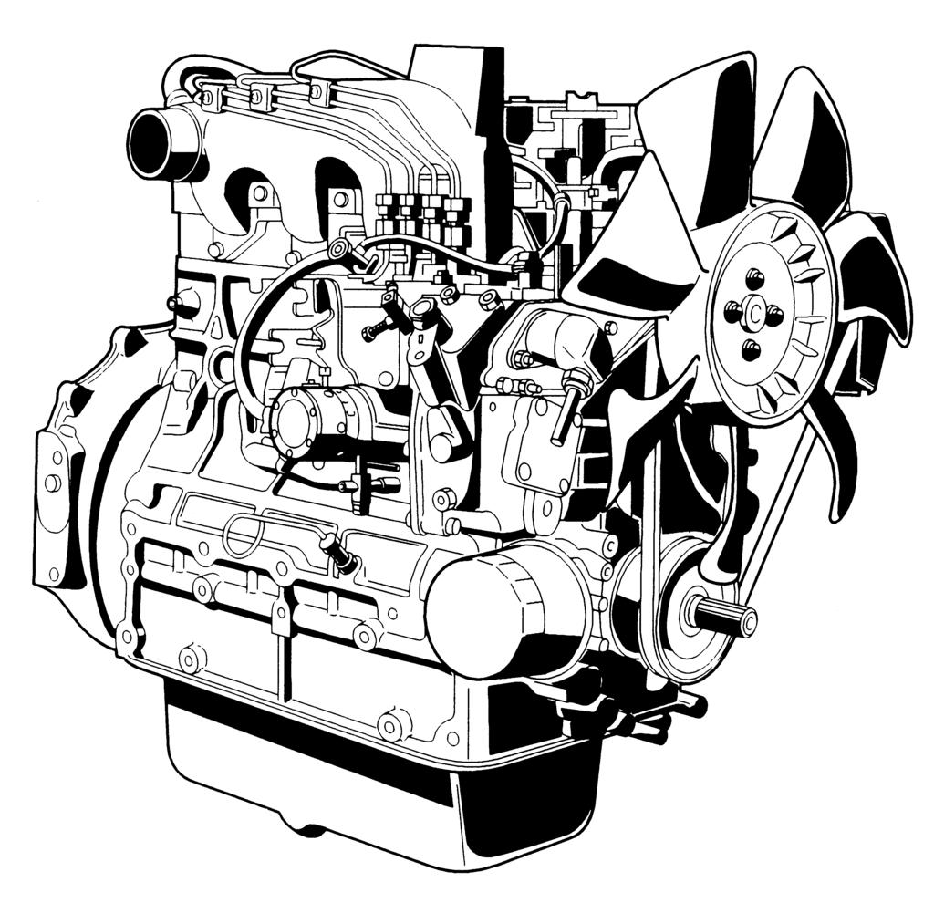
13 2 NAMES OF PARTS NAMES OF PARTS (1) Intake manifold (2) Speed control lever (3) Engine stop lever (4) Injection pump (5) Fuel feed pump (6) Cooling fan (7) Fan drive pulley (8) Oil filter cartridge (9) Water drain cock (10) Oil filler plug (11) Exhaust manifold (12) Alternator (13) Starter (14) Oil level gauge (15) Oil pressure switch (16) Flywheel (17) Oil drain plug (18) Oil pan (19) Engine hook
14 PRE-OPERATION CHECK PRE-OPERATION CHECK BREAK-IN During the engine break-in period, observe the following by all means: 1. Change engine oil and oil filter cartridge after the first 50 hours of operation. (See "ENGINE OIL" in "PERIODIC SERVICE" section.) 2. When ambient temperature is low, operate the machine after the engine has been completely warmed up. DAILY CHECK To prevent trouble from occurring, it is important to know the conditions of the engine well. Check it before starting. 3 To avoid personal injury: A Be sure to install shields and safeguards attached to the engine when operating. A Stop the engine at a flat and wide space when checking. A Keep dust or fuel away from the battery, wiring, muffler and engine to prevent a fire. Check and clear them before operating everyday. Pay attention to the heat of the exhaust pipe or exhaust gas so that it can not ignite trash. Item Ref. page 1. Parts which had trouble in previous operation - 2. By walking around the machine (1) Oil or water leaks 15 to 20 (2) Engine oil level and contamination 15,16 (3) Amount of fuel 12 (4) Amount of coolant 18 to 20 (5) Dust in air cleaner dust cup 21 (6) Damaged parts and loosened bolts and nuts - 3. By inserting the key into the starter switch (1) Proper functions of meters and pilot lamps; no stains on these parts - (2) Proper function of glow lamp timer - 4. By starting the engine (1) Color of exhaust fumes 7 (2) Unusual engine noise 7 (3) Engine start-up condition 5 (4) Slow-down and acceleration behavior 7
15 4 OPERATING THE ENGINE OPERATING THE ENGINE STARTING THE ENGINE(NORMAL) 1. Set the fuel lever to the "ON" position. To avoid personal injury: A Do not allow children to approach the machine while the engine is running. A Be sure to install the machine on which the engine is installed, on a flat place. A Do not run the engine on gradients. A Do not run the engine in an enclosed area. Exhaust gas can cause air pollution and exhaust gas poisoning. A Keep your hands away from rotating parts (such as fan, pulley, belt, flywheel etc.) during operation. A Do not operate the machine while under the influence of alcohol or drugs. A Do not wear loose, torn or bulky clothing around the machine. It may catch on moving parts or controls, leading to the risk of accident. Use additional safety items, e.g. hard hat, safety boots or shoes, eye and hearing protection, gloves, etc., as appropriate or required. A Do not wear radio or music headphones while operating engine. A Check to see if it is safe around the engine before starting. A Reinstall safeguards and shields securely and clear all maintenance tools when starting the engine after maintenance. A Do not use ether or any starting fluid for starting the engine, or a severe damage will occur. A When starting the engine after a long storage (of more than 3 months), first set the stop lever to the "STOP" position and then activate the starter for about 10 seconds to allow oil to reach every engine part. (1) Fuel lever (A) "ON" (B) "OFF" 2. Place the engine stop lever to the "START" position. 3. Place the speed control lever at more than half "OPERATION". (1) Engine stop lever (2) Speed Control lever (A) "STOP" (B) "START" (C) "IDLING" (D) "OPERATION"
16 OPERATING THE ENGINE 5 4. Insert the key into the key switch and turn it to the "OPERATION" position. 8. Warm up the engine at medium speed without load. A If the glow lamp should redden too quickly or too slowly, immediately ask your KUBOTA dealer to check and repair it. A If the engine does not catch or start at 10 seconds after the starter switch is set at "STARTING" position, wait for another 30 seconds and then begin the engine starting sequence again. Do not allow the starter motor to run continuously for more than 20 seconds. (A) "OFF" SWITCHED OFF (B) "ON" OPERATION (C) "GL" PREHEATING (D) "ST" STARTING (A) "GL" PREHEATING (B) "OFF" SWITCHED OFF (C) "ON" OPERATION (D) "ST" STARTING COLD WEATHER STARTING If the ambient temperature is below -5 C(23 F)* and the engine is very cold, start it in the following manner: Take steps (1) through (4) above. 5. Turn the key to the "PREHEATING" position and keep it there for a certain period mentioned below. 5. Turn the starter switch to the "PREHEATING" position to allow the glow lamp to redden. (with lamp timer in use) A The glow lamp goes out in about 5 seconds when the lamp timer is up. Refer to this for pre-heating. Even with the glow lamp off, the glow plug can be preheated by turning the starter switch to the "PREHEATING" position. 6. Turn the key to the "STARTING" position and the engine should start. Release the key immediately when the engine starts. 7. Check to see that the oil pressure lamp and charge lamp are off. If the lamps are still on, immediately stop the engine, and determine the cause. (See "CHECKS DURING OPERATION" in "OPERATING THE ENGINE" section.) A If the oil pressure lamp should be still on, immediately stop the engine and check; - if there is enough engine oil. - if the engine oil has dirt in it. - if the wiring is faulty. A Shown below are the standard preheating times for various temperatures. This operation, however, is not required, when the engine is warmed up. Ambient temperature Preheating time Above 10 C (50 F) NO NEED 10 C (50 F) to -5 C (23 F) Approx. 5 seconds *Below -5 C (23 F) Approx. 10 seconds Limit of continuous use 20 seconds 6. Turn the key to the "STARTING" position and the engine should start. (If the engine fails to start after 10 seconds, turn off the key for 5 to 30 seconds. Then repeat steps (5) and (6).) A Do not allow the starter motor to run continuously for more than 20 seconds. A Be sure to warm up the engine, not only in winter, but also in warmer seasons. An insufficiently warmed-up engine can shorten its service life. A When there is fear of temperature dropping below -15 C (5 F) detach the battery from the machine, and keep it indoors in a safe area, to be reinstalled just before the next operation.
17 6 OPERATING THE ENGINE STOPPING THE ENGINE 1. Return the speed control lever to low idle, and run the engine under idling conditions. 2. Set the engine stop lever to the "STOP" position. 3. With the starter switch placed to the "SWITCHED OFF" position, remove the key. (Be sure to return the engine stop lever to the "START" position to be ready for the next start.) CHECKS DURING OPERATION While running, make the following checks to see that all parts are working correctly. BRadiator Cooling water(coolant) To avoid personal injury: A Do not remove radiator cap until coolant temperature is well below its boiling point. Then loosen cap slightly to the stop position, to relieve any pressure, before removing cap completely. (1) Engine stop lever (2) Speed control lever (A) "STOP" (B) "START" (C) "IDLING" (D) "OPERATION" A If equipped with a turbo-charger, allow the engine to idle for 5 minutes before shutting it off after a full load operation. Failure to do so may lead to turbo-charger trouble. If the coolant temperature warning lamp lights up or if steam or coolant does not stop squirting from the radiator overflow pipe, turn off the load and keep the engine idling (COOLING-DOWN) for at least 5 minutes to let it cool down gradually. Then stop the engine and take the following inspection and servicing. 1. Check to see if the coolant runs short or if there is any coolant leak; 2. Check to see if there is any obstacle around the cooling air inlet or outlet; 3. Check to see if there is any dirt or dust between radiator fins and tube; 4. Check to see if the fan belt is too loose; and 5. Check to see if radiator water pipe is clogged. BOil pressure lamp The lamp lights up to warn the operator that the engine oil pressure has dropped below the prescribed level. If this should happen during operation or should not go off even after the engine is accelerated more than 1000rpm, immediately stop the engine and check the following: 1. Engine oil level (See "ENGINE OIL" in "PERIODIC SERVICE" section.)
18 OPERATING THE ENGINE 7 BFuel REVERSED ENGINE REVOLUTION AND REMEDIES To avoid personal injury: A Fluid escaping from pinholes may be invisible. Do not use hands to search for suspected leaks; Use a piece of cardboard or wood, instead. If injured by escaping fluid, see a medical doctor at once. This fluid can produce gangrene or a severe allergic reaction. A Check any leaks from fuel pipes or fuel injection pipes. Use eye protection when checking for leaks. Be careful not to empty the fuel tank. Otherwise air may enter the fuel system, requiring fuel system bleeding. (See "FUEL" in "PERIODIC SERVICE" section.) BColor of exhaust While the engine is run within the rated output range: A The color of exhaust remains colorless. A If the output slightly exceeds the rated level, exhaust may become a little colored with the output level kept constant. A If the engine is run continuously with dark exhaust emission, it may lead to trouble with the engine. BImmediately stop the engine if; A The engine suddenly slows down or accelerates. A Unusual noises are suddenly heard. A Exhaust fumes suddenly become very dark. A The oil pressure lamp or the water temperature alarm lamp lights up. To avoid personal injury: A Reversed engine operation can make the machine reverse and run it backwards. It may lead to serious trouble. A Reversed engine operation may make exhaust gas gush out into the intake side and ignite the air cleaner; It could catch fire. Reversed engine revolution must be stopped immediately since engine oil circulation is cut quickly, leading to serious trouble. BHow to tell when the engine starts running backwards 1. Lubricating oil pressure drops sharply. Oil pressure warning light, if used, will light. 2. Since the intake and exhaust sides are reversed, the sound of the engine changes, and exhaust gas will come out of the air cleaner. 3. A louder knocking sound will be heard when the engine starts running backwards. BRemedies 1. Immediately set the engine stop lever to the "STOP" position to stop the engine. 2. After stopping the engine, check the air cleaner, intake rubber tube and other parts, and then replace parts as needed.
19 8 MAINTENANCE MAINTENANCE To avoid personal injury: A Be sure to conduct daily checks, periodic maintenance, refueling or cleaning on a level surface with the engine shut off and remove the key. A Before allowing other people to use your engine, explain how to operate, and have them read this manual before operation. A When cleaning any parts, do not use gasoline but use regular cleanser. A Always use proper tools, that are in good condition. Make sure you understand how to use them, before performing any service work. A When installing, be sure to tighten all bolts lest they should be loose. Tighten the bolts by the specified torque. A Do not put any tools on the battery, or battery terminals may short out. Severe burns or fire could result. Detach the battery from the engine before maintenance. A Do not touch muffler or exhaust pipes while they are hot; Severe burns could result.
20 MAINTENANCE 9 SERVICE INTERVALS Observe the following for service and maintenance. Interval Item Ref. page Every 50 hours Check of fuel pipes and clamp bands See NOTE Change of engine oil (depending on the oil pan) 15 to 17 Every 100 hours Every 200 hours Every 200 hours of operation or six months Every 400 hours Cleaning of air cleaner element 21 Cleaning of fuel filter 14 Check of fan belt tightness 22 Draining water separator - Replacement of oil filter cartridge (depending on the oil pan) 17 Check of intake air line Check of radiator hoses and clamp bands 19 Replacement of fuel filter cartridge Cleaning of water separator - Removal of sediment in fuel tank - Every 500 hours Cleaning of water jacket (radiator interior) 18 to 20 Replacement of fan belt 22 Every year Replacement of air cleaner element 21 Every 800 hours Check of valve clearance - *3 Every 1500 hours Check of fuel injection nozzle injection pressure - Every 3000 hours Every two years Check of turbo charger - Check of injection pump - Change of radiator coolant (L.L.C.) 18 to 20 Replacement of radiator hoses and clamp bands 19 Replacement of fuel pipes and clamp bands 14 Replacement of intake air line -
21 10 MAINTENANCE A The jobs indicated by must be done after the first 50 hours of operation. *1 Air cleaner should be cleaned more often in dusty conditions than in normal conditions. *2 After 6 times of cleaning. *3 Consult your local KUBOTA Dealer for this service. *4 Replace only if necessary. A The items listed above (@ marked) are registered as emission related critical parts by KUBOTA in the U.S. EPA nonroad emission regulation. As the engine owner, you are responsible for the performance of the required maintenance on the engine according to the above instruction. Please see the Warranty Statement in detail. A Changing interval of engine oil Models *Oil pan depth 124 mm (4.88 in.) *90 mm (3.54 in.) All models 200 Hrs 150 Hrs Initial 50 Hrs * 90 mm (3.54 in.) oil pan depth is optional. (Standard replacement interval) A American Petroleum Institute (API) classification: above CF-4 grade A Ambient temperature: below 35 C (95 F) Lubricating oil With strict emission control regulations now in effect, the CF-4 and CG-4 engine oils have been developed for use with low sulfur fuels, for On-Highway vehicle engines. When a Non-Road engine runs on high sulfur fuel, it is advisable to use a "CF or better" classification engine oil with a high Total Base Number (a minimum TBN of 10 is recommended). A Lubricating oil recommended when a low-sulfur or high-sulfur fuel is employed. : Recommendable X : Not recommendable Lubricating **Fuel Remarks oil classification Low-sulfur High-sulfur CF *TBN 10 CF-4 X CG-4 X CH-4 X CI-4 X * TBN: Total Base Number **Fuel A Diesel Fuel Specification Type and Sulfur Content % (ppm) used, must be compliant with all applicable emission regulations for the area in which the engine is operated. A Use of diesel fuel with sulfur content less than 0.10 % (1000 ppm) is strongly recommended. A If high-sulfur fuel (sulfur content 0.50 % (5000 ppm) to 1.0 % (10000 ppm)) is used as a diesel fuel, change the engine oil and oil filter at shorter intervals. (approximately half). A DO NOT USE Fuels that have sulfur content greater than 1.0 % (10000 ppm). A Since KUBOTA diesel engines of less than 56 kw (75 hp) utilize EPA Tier 4 and Interim Tier 4 standards, the use of ultra low sulfur fuel is mandatory for these engines, when operated in US EPA regulated areas. Therefore, please use No.2-D S15 diesel fuel as an alternative to No.2-D, and use No.1-D S15 diesel fuel as an alternative to No.1-D for ambient temperatures below -10 (14 ). No.1-D or No.2-D, S15 : Ultra Low Sulfur Diesel (ULSD) 15 ppm or wt.% A CJ-4 classification oil is intended for use in engines equipped with DPF (Diesel Particulate Filter) and is Not Recommended for use in Kubota E3 specification engines.
22 MAINTENANCE 11 A Oil used in the engine should have API classification and Proper SAE Engine Oil according to the ambient temperatures as shown below: Above 25 (77 ) SAE30, SAE10W-30 or 15W to 25 (14 to 77 ) SAE10W-30 or 15W-40 Below -10 (14 ) SAE10W-30 A Recommended API classification Refer to the following table for the suitable American Petroleum Institute (API) classification of engine oil according to the engine type (with internal EGR, external EGR or non-egr) and the Fuel Type Used : (Ultra Low Sulfur or High Sulfur Fuels). Fuel type High Sulfur Fuel [0.05 % (500 ppm) Sulfur Content < 0.50 % (5000 ppm)] Ultra Low Sulfur Fuel [Sulfur Content < % (15 ppm)] EGR: Exhaust Gas Re-circulation Engine oil classification (API classification) Engines with non-egr Engines with external EGR Engines with internal EGR CF (If the "CF-4, CG-4, CH-4 or CI-4" engine oil is used with a high-sulfur fuel, change the engine oil at shorter intervals. (approximately half)) CF, CF-4, CG-4, CH-4 or CI CF or CI-4 (Class CF-4, CG-4 and CH-4 engine, oils cannot be used on EGR type engines.)
23 12 PERIODIC SERVICE PERIODIC SERVICE FUEL Fuel is flammable and can be dangerous. You should handle fuel with care. To avoid personal injury: A Do not mix gasoline or alcohol with diesel fuel. This mixture can cause an explosion. A Be careful not to spill fuel during refueling. If fuel should spill, wipe it off at once, or it may cause a fire. A Do not fail to stop the engine before refueling. Keep the engine away from the fire. A Be sure to stop the engine while refueling or bleeding and when cleaning or changing fuel filter or fuel pipes. Do not smoke when working around the battery or when refueling. A Check the fuel systems at a well ventilated and wide place. A When fuel and lubricant are spilled, refuel after letting the engine cool off. A Always keep spilled fuel and lubricant away from engine. BFuel level check and refueling 1. Check to see that the fuel level is above the lower limit of the fuel level gauge. 2. If the fuel is too low, add fuel to the upper limit. Do not overfill. Flash Point, ( ) Water and Sediment, volume % Carbon Residue on, 10 percent Residuum, % Ash, weight % Min Max Max Max 52 (125) Distillation Temperatures, ( ) 90% Point Viscosity Kinematic cst or mm /s at 40 Viscosity Saybolt, SUS at 37.8 (100 ) Min Max Min Max Min Max 282 (540) 338 (640) Sulfur, weight % Copper Strip Corrosion Cetane Number Max Max Min 0.50 No A Cetane Rating : The minimum recommended Fuel Cetane Rating is 45. A cetane rating greater than 50 is preferred, especially for ambient temperatures below -20 (-4 ) or elevations above 1500 m (5000 ft). A Diesel Fuel Specification Type and Sulfur Content % (ppm) used, must be compliant with all applicable emission regulations for the area in which the engine is operated. A Use of diesel fuel with sulfur content less than 0.10 % (1000 ppm) is strongly recommended. A If high-sulfur fuel (sulfur content 0.50 % (5000 ppm) to 1.0 % (10000 ppm)) is used as a diesel fuel, change the engine oil and oil filter at shorter intervals. (approximately half). A DO NOT USE Fuels that have sulfur content greater than 1.0 % (10000 ppm). A Diesel fuels specified to EN 590 or ASTM D975 are recommended. A No.2-D is a distillate fuel of lower volatility for engines in industrial and heavy mobile service. (SAE J313 JUN87) A Since KUBOTA diesel engines of less than 56 kw (75 hp) utilize EPA Tier 4 and Interim Tier 4 standards, the use of ultra low sulfur fuel is mandatory for these engines, when operated in US EPA regulated areas. Therefore, please use No.2-D S15 diesel fuel as an alternative to No.2-D, and use No.1-D S15 diesel fuel as an alternative to No.1-D for ambient temperatures below -10 (14 ). 1) SAE : Society of Automotive Engineers 2) EN : European Norm 3) ASTM : American Society of Testing and Materials 4) US EPA : United States Environmental Protection Agency 5) No.1-D or No.2-D, S15 : Ultra Low Sulfur Diesel (ULSD) 15 ppm or wt.%
24 PERIODIC SERVICE 13 A Be sure to use a strainer when filling the fuel tank, or dirt or sand in the fuel may cause trouble in the fuel injection pump. A For fuel, always use diesel fuel. You are required not to use alternative fuel, because its quality is unknown or it may be inferior in quality. Kerosene, which is very low in cetane rating, adversely affects the engine. Diesel fuel differs in grades depending on the temperature. A Be careful not to let the fuel tank become empty, or air can enter the fuel system, necessitating bleeding before next engine start. [GRAVITY FEED SYSTEM] BAir bleeding the fuel system To avoid personal injury; A Do not bleed a hot engine as this could cause fuel to spill onto a hot exhaust manifold creating a danger of fire. Air bleeding of the fuel system is required if; A after the fuel filter and pipes have been detached and refitted; A after the fuel tank has become empty; or A before the engine is to be used after a long storage. [PROCEDURE ] (gravity feed fuel tanks only) 1. Fill the fuel tank to the fullest extent. Open the fuel filter lever. 2. Open the air vent cock on top of the fuel injection pump. 3. Turn the engine, continue it for about 10 seconds, then stop it, or move the fuel feed pump lever by hand (optional). 4. Close the air vent cock on top of the fuel injection pump. (1) Air vent cock (2) Fuel feed pump [PROCEDURE ] (fuel tanks lower than injection pump) 1. For fuel tanks that are lower than the injection pump. The fuel system must be pressurized by the fuel system electric fuel pump. 2. If an electric fuel pump is not used, you must manually actuate the pump by lever to bleed. 3. The primary fuel filter must be on the pressure side of the pump if the fuel tank is lower than the injection pump. 4. To bleed, follow (2) through (4) above. A Tighten air vent plug of the fuel injection pump except when bleeding, or it may stop the engine suddenly. [TANK BELOW INJECTION PUMP SYSTEM] A Always keep the air vent cock on the fuel injection pump closed except when air is vented, or it may cause the engine to stop. (1) Fuel tank below injection pump (2) Pre-filter (3) Electric or Mechanical pump (4) Main Filter (5) Injection pump
25 14 PERIODIC SERVICE BChecking the fuel pipes To avoid personal injury; A Check or replace the fuel pipes after stopping the engine. Broken fuel pipes can cause fires. BCleaning the fuel filter pot Every 100 hours of operation, clean the fuel filter in a clean place to prevent dust intrusion. 1. Close the fuel filter lever. Check the fuel pipes every 50 hours of operation. When if; 1. If the clamp band is loose, apply oil to the screw of the band, and tighten the band securely. 2. If the fuel pipes, made of rubber, become worn out, replace them and clamp bands every 2 years. 3. If the fuel pipes and clamp bands are found worn or damaged before 2 years' pass, replace or repair them at once. 4. After replacement of the pipes and bands, air-bleed the fuel system. A When the fuel pipes are not installed, plug them at both ends with clean cloth or paper to prevent dirt from entering. Dirt in the pipes can cause fuel injection pump malfunction. (1) Fuel filter lever (2) Fuel filter pot (A) "OFF" (B) "ON" 2. Remove the top cap, and rinse the inside with diesel fuel. 3. Take out the element, and rinse it with diesel fuel. 4. After cleaning, reinstall the fuel filter, keeping out of dust and dirt. 5. Air-bleed the injection pump. A Entrance of dust and dirt can cause a malfunction of the fuel injection pump and the injection nozzle. Wash the fuel filter cup periodically. (1) Clamp band (2) Fuel pipe (1) O ring (2) Filter element (3) Spring (4) Filter bowl (5) Screw ring
26 PERIODIC SERVICE 15 BFuel filter cartridge replacement 1. Replace the fuel filter cartridge with a new one every 400 operating hours. 2. Apply fuel oil thinly over the gasket and tighten the cartridge into position by hand-tightening only. 3. Finally, vent the air. A Replace the fuel filter cartridge periodically to prevent wear of the fuel injection pump plunger or the injection nozzle, due to dirt in the fuel. ENGINE OIL To avoid personal injury: A Be sure to stop the engine before checking and changing the engine oil and the oil filter cartridge. A Do not touch muffler or exhaust pipes while they are hot; Severe burns could result. Always stop the engine and allow it to cool before conducting inspections, maintenance, or for a cleaning procedure. A Contact with engine oil can damage your skin. Put on gloves when using engine oil. If you come in contact with engine oil, wash it off immediately. (1) Fuel filter cartridge (2) Air vent plug (3) O ring (4) Pipe joint (5) Cover A Be sure to inspect the engine, locating it on a level place. If placed on gradients accurately, oil quantity may not be measured. BChecking oil level and adding engine oil 1. Check the engine oil level before starting or more than 5 minutes after stopping the engine. 2. Remove the oil level gauge, wipe it clean and reinstall it. 3. Take the oil level gauge out again, and check the oil level. (1) Oil filler plug (2) Oil level gauge [Lower end of oil level gauge] (A) Engine oil level within this range is proper.
27 16 PERIODIC SERVICE 4. If the oil level is too low, remove the oil filler plug, and add new oil to the prescribed level. 5. After adding oil, wait more than 5 minutes and check the oil level again. It takes some time for the oil to drain down to the oil pan. Engine oil quantity Models D1503-M-E3 D1703-M-E3 D1803-M-E3 D1703-M-E3BG V2003-M-E3 V2203-M-E3 V2403-M-E3 V2403-M-T-E3 V2003-M-E3BG V2003-M-T-E3BG V2203-M-E3BG V2403-M-E3BG 124 mm (4.88 in.) *Oil pan depth * 90 mm (3.54 in.) oil pan depth is optional. Oil quantities shown are for standard oil pans. *90 mm (3.54 in.) A Engine oil should be MIL-L-2104C or have properties of API classification CF or higher. Change the type of engine oil according to the ambient temperature. Above 25 C (77 F) -10 C to 25 C (14 F to 77 F) Below -10 C (32 F) 7.0 L (1.85 U.S.gals.) 9.5 L (2.51 U.S.gals.) SAE L (1.48 U.S.gals.) 7.6 L (2.01 U.S.gals.) or SAE10W-30 SAE15W-40 SAE10W-30 or SAE15W-40 SAE10W-30 BChanging engine oil To avoid personal injury: A Be sure to stop the engine before draining engine oil. A When draining engine oil, place some container underneath the engine and dispose it according to local regulations. A Do not drain oil after running the engine. Allow engine to cool down sufficiently. 1. Change oil after the initial 50 hours of operation and every 200 hours thereafter. (See table below.) A Changing interval thereafter *Oil pan depth Models 124 mm (4.88 in.) *90 mm (3.54 in.) All models 200 Hrs 150 Hrs Initial 50 Hrs * 90 mm (3.54 in) oil pan depth is optional. (Standard replacement interval) A API classification : above CF A Ambient temperature : below 35 C (95 F ) 2. Remove the drain plug at the bottom of the engine, and drain all the old oil. Drain oil will drain easier when the oil is warm. A When using oil of different brands from the previous one, be sure to drain all the previous oil before adding the new engine oil. (1) Oil drain plug 3. Add new engine oil up to the upper limit of the oil level gauge.
28 PERIODIC SERVICE 17 BReplacing the oil filter cartridge To avoid personal injury: A Be sure to stop the engine before changing the oil filter cartridge. A Allow engine to cool down sufficiently, oil can be hot and cause burns. 1. Replace the oil filter cartridge. Oil filter cartridge should be replaced, as following operation hours. *Oil pan depth Models 124 mm (4.88 in.) *90 mm (3.54 in.) All models 200 Hrs 150 Hrs Initial 50 Hrs * 90 mm (3.54 in.) oil pan depth is optional. 2. Remove the old oil filter cartridge with a filter wrench. 3. Apply a film of oil to the gasket for the new cartridge. 4. Screw in the cartridge by hand. When the gasket contacts the seal surface, tighten the cartridge enough by hand. Because, if you tighten the cartridge with a wrench, it will be tightened too much. RADIATOR Coolant will last for one day's work if filled all the way up before operation start. Make it a rule to check the coolant level before every operation. To avoid personal injury: A Do not stop the engine suddenly, stop it after about 5 minutes of unloaded idling. A Work only after letting the engine and radiator cool off completely (more than 30 minutes after it has been stopped). A Do not remove the radiator cap while coolant is hot. When cool to the touch, rotate cap to the first stop to allow excess pressure to escape. Then remove cap completely. If overheats should occur, steam may gush out from the radiator or recovery tank; Severe burns could result. (1) Oil filter cartridge (2) Remove with a filter wrench (Tighten with your hand) 5. After the new cartridge has been replaced, the engine oil level normally decreases a little. Thus, run the engine for a while and check for oil leaks through the seal before checking the engine oil level. Add oil if necessary. A Wipe off any oil sticking to the machine completely.
29 18 PERIODIC SERVICE BChecking coolant level, adding coolant 1. Remove the radiator cap, after the engine has completely cooled, and check to see that coolant reaches the supply port. 3. When the coolant level drops due to evaporation, add water only up to the full level. 4. Check to see that two drain cocks; one is at the crankcase side and the other is at the lower part of the radiator as figures below. (1) Radiator pressure cap 2. If the radiator is provided with a recovery tank, check the coolant level of the recovery tank. When it is between the "FULL" and "LOW" marks, the coolant will last for one day's work. (1) Coolant drain cock (1) Recovery tank (A) "FULL" (B) "LOW" A If the radiator cap has to be removed, follow the caution and securely retighten the cap. A If coolant should be leak, consult your local KUBOTA dealer. A Make sure that muddy or sea water does not enter the radiator. A Use clean, fresh water and 50% anti-freeze to fill the recovery tank. A Do not refill recovery tank with coolant over the "FULL" level mark. A Be sure to close the radiator cap securely. If the cap is loose or improperly closed, coolant may leak out and decrease quickly.
30 PERIODIC SERVICE 19 BChanging coolant 1. To drain coolant, always open both drain cocks and simultaneously open the radiator cap as well. With the radiator cap kept closed, a complete drain of water is impossible. 2. Remove the overflow pipe of the radiator pressure cap to drain the recovery tank. 3. Prescribed coolant volume (U.S.gallons) Models D1503-M-E3 D1703-M-E3 D1703-M-E3BG D1803-M-E3 V2003-M-E3 V2203-M-E3 V2003-M-E3BG V2003-M-T-E3BG V2203-M-E3BG V2403-M-E3 V2403-M-T-E3 V2403-M-E3BG A Coolant quantities shown are for standard radiators. 4. An improperly tightened radiator cap or a gap between the cap and the seat quickens loss of coolant. 5. Coolant (Radiator cleaner and anti-freeze) Season All seasons Quantity 5.5 L (1.45 U.S.gals.) 5.8 L (1.53 U.S.gals.) 8.1 L (2.14 U.S.gals.) 8.4 L (2.22 U.S.gals.) Coolant Pure water and anti-freeze (See "Anti-freeze" in RADIATOR section.) BRemedies for quick decrease of coolant 1. Check any dust and dirt between the radiator fins and tube. If any, remove them from the fins and the tube. 2. Check the tightness of the fan belt. If loose, tighten it securely. 3. Check the internal blockage in the radiator hose. If scale forms in the hose, clean with the scale inhibitor or its equivalent. BChecking radiator hoses and clamp bands To avoid personal injury: A Be sure to check radiator hoses and clamp bands periodically. If radiator hose is damaged or coolant leaks, overheats or severe burns could occur. Check to see if radiator hoses are properly fixed every 200 hours of operation or 6 months, whichever comes first. 1. If hose clamps are loose or water leaks, tighten hose clamp securely. 2. Replace hoses and tighten hose clamps securely, if radiator hoses are swollen, hardened or cracked. Replace hoses and hose clamps every 2 years or earlier, if checked and found that hoses are swollen, hardened or cracked. BPrecaution at overheating The event that the coolant temperature is nearly or more than the boiling point is called "OVERHEATING". While running, make the following checks to see that all parts are working correctly. If anything is unusual, inspect it, referring to the relevant description in "MAINTENANCE" and "PERIODIC SERVICE" section. C Coolant If the coolant temperature warning lamp lights up or if steam or coolant does not stop squirting from the radiator overflow pipe, turn off the load and keep the engine idling (COOLING-DOWN) for at least 5 minutes to let it cool down gradually. Then stop the engine and take the following inspection and servicing. 1. Check to see if the coolant runs short or if there is any coolant leak; 2. Check to see if there is any obstacle around the cooling air inlet or outlet; 3. Check to see if there is any dirt or dust between radiator fins and tube; 4. Check to see if the fan belt is too loose; and 5. Check to see if radiator water pipe is clogged. BCleaning radiator core (outside) If dust is between the fin and tube, wash it away with running water. A Do not clean radiator with firm tools such as spatulas or screwdrivers. They may damage specified fin or tube. It can cause coolant leaks or decrease cooling performance.
31 20 PERIODIC SERVICE BCleaning the radiator (inside) 1. Clean up the coolant line inside in the following cases. A As per the SERVICE INTERVALS list. A When changing the coolant. 2. Use a radiator cleaning agent. This helps wash away scale deposits. BAnti-freeze Vol % Anti-freeze Freezing Point Boiling Point * *At x 10 Pa (760 mmhg) pressure (atmospheric). A higher boiling point is obtained by using a radiator pressure cap which permits the development of pressure within the cooling system. To avoid personal injury: A When using anti-freeze, put on some protection such as rubber gloves (Anti-freeze contains poison.). A If should drink anti-freeze, throw up at once and take medical attention. A When anti-freeze comes in contact with the skin or clothing, wash it off immediately. A Do not mix different types of antifreeze. The mixture can produce chemical reaction causing harmful substances. A Anti-freeze is extremely flammable and explosive under certain conditions. Keep fire and children away from anti-freeze. A When draining fluids from the engine, place some container underneath the engine body. A Do not pour waste onto the grounds, down a drain, or into any water source. A Also, observe the relevant environmental protection regulations when disposing of antifreeze. Always use a 50/50 mix of long-life coolant and clean soft water in KUBOTA engines. Contact KUBOTA concerning coolant for extreme conditions. 1. Long-life coolant (hereafter LLC) comes in several types. Use ethylene glycol (EG) type for this engine. 2. Before employing LLC-mixed cooling water, flush the radiator with fresh water. Repeat this procedure 2 or 3 times to clean up the radiator and engine block from inside. 3. Mixing the LLC Premix 50% LLC with 50% clean soft water. When mixing, stir it up well, and then fill into the radiator. 4. The procedure for the mixing of water and anti-freeze differs according to the make of the anti-freeze. Refer to SAE J1034 standard, more specifically also to SAE J814c. 5. Adding the LLC (1) Add only water if the coolant level reduces in the cooling system by evaporation. (2) If there is a coolant leak, add the LLC of the same manufacturer and type in the same coolant percentage. *Never add any long-life coolant of different manufacturer. (Different brands may have different additive components, and the engine may fail to perform as specified.) 6. When the LLC is mixed, do not employ any radiator cleaning agent. The LLC contains anti-corrosive agent. If mixed with the cleaning agent, sludge may build up, adversely affecting the engine parts. 7. Kubota's genuine long-life coolant has a service life of 2 years. Be sure to change the coolant every 2 years. A The above data represents industry standards that necessitate minimum glycol content in the concentrated anti-freeze.
California Proposition 65 WARNING
 California Proposition 65 WARNING Engine exhaust, some of its constituents, certain vehicle components and fluids, contain or emit chemicals known to the State of California to cause cancer and birth defects
California Proposition 65 WARNING
 California Proposition 65 WARNING Engine exhaust, some of its constituents, certain vehicle components and fluids, contain or emit chemicals known to the State of California to cause cancer and birth defects
California Proposition 65 WARNING
 California Proposition 65 WARNING Engine exhaust, some of its constituents, certain vehicle components and fluids, contain or emit chemicals known to the State of California to cause cancer and birth defects
OPERATOR'S MANUAL LIQUID COOLED MODELS WG1605-G-E3 WG1605-L-E3 WG1605-GL-E3 READ AND SAVE THIS BOOK EG BGAAAIAP0020 1BGAAAIAP0020
 OPERATOR'S MANUAL KUBOTA LIQUID COOLED GASOLINE/LPG ENGINE MODELS WG1605-G-E3 WG1605-L-E3 WG1605-GL-E3 1BGAAAIAP0020 1BGAAAIAP0020 EG523-8916-2 READ AND SAVE THIS BOOK FOREWORD You are now the proud owner
Voltmaster Centrifugal Trash Pumps
 Voltmaster Centrifugal Trash Pumps Model TSP2, TSP3 and TSP4 Owner s Manual February 2011 Table of Contents 1 Introduction............................ 1 1.1 Read before using..................... 1 1.2
Light condition and operation Windshield glass condition Wiper blade condition Paint condition and corrosion Fluid leaks Door and hood lock condition
 GENERAL CHECKS Engine Compartment The following should be checked regularly: Engine oil level and condition Transmission fluid level and condition Brake fluid level Clutch fluid level Engine coolant level
FOREWORD. DANGER : Indicates an imminently hazardous situation which, if not avoided, will result in death or serious injury.
 G3601-8911-8 3 WARNING Before the generator can be connected to a building's electrical system, a licensed electrician must install an isolation (transfer) switch in the building's main fuse box. The switch
WORK SHOP MANUAL ENGINE BASE
 WORK SHOP MANUAL ENGINE BASE N2.14 (Before the serial number KTB09010509) NANNI INDUSTRIES S.A.S Zone Industrielle 11 avenue MARIOTTE B.P.107 33260 LA TESTE - FRANCE 60300175 TO THE READER This Workshop
AIR-COOLED DIESEL GENERATOR OWNERʼS MANUAL. This manual contains important safety information. TDG2500E TDGW7000E TDG7000SE TDG4500E
 AIR-COOLED DIESEL GENERATOR OWNERʼS MANUAL This manual contains important safety information. TDG2500E TDGW7000E TDG7000SE TDG4500E TDG8000-3 TDG7000SE-3 TDG7000E TDG8000E TDGW7000SE TDG7000E3 TDGW8000E
GL6000-STD GL6000-AUS GL7000-USA GL7000-USA-TM GL7000-STD GL9000-STD GL9000-AUS GL11000-USA GL11000-USA-TM GL11000-STD
 GL6000-STD GL6000-AUS GL7000-USA GL7000-USA-TM GL7000-STD GL9000-STD GL9000-AUS GL11000-USA GL11000-USA-TM GL11000-STD D-2396 D-2397 3 WARNING To prevent electrical shock the following instruction must
WORK SHOP MANUAL ENGINE BASE
 WORK SHOP MANUAL ENGINE BASE N2.14 (starting the serial number KTB09010509) NANNI INDUSTRIES S.A.S Zone Industrielle 11 avenue MARIOTTE B.P.107 33260 LA TESTE - FRANCE 60300176 TO THE READER This Workshop
Maintenance of Pleasureboat Diesel Engine GM Series
 Maintenance of Pleasureboat Diesel Engine GM Series.Safety Precaution for Inspection )Battery Fluid Battery fluid is diluted sulfuric acid. It can blind you if it gets in your eyes, or burn your skin.
SECTION 6 2 SERVICE PROCEDURES AND SPECIFICATIONS. Engine. Specifications
 SERVICE PROCEDURES AND SPECIFICATIONS Engine SECTION 6 2 Specifications........................................... 170 Fuel.................................................... 172 Facts about engine oil
TP300 INDUSTRIAL TRASH PUMP OPERATOR S MANUAL
 TP300 INDUSTRIAL TRASH PUMP OPERATOR S MANUAL IT IS EXTREMELY IMPORTANT TO READ AND UNDERSTAND THE ENTIRE CONTENTS OF THIS OPERATOR S MANUAL BEFORE ATTEMPTING TO OPERATE THE PRODUCT. THIS EQUIPMENT IS
Installation Instructions for Aux 101 Kit A044Z055
 Instruction Sheet 7-2013 Installation Instructions for Aux 101 Kit A044Z055 1 Introduction The information contained within is based on information available at the time of going to print. In line with
WORKSHOP MANUAL DIESEL ENGINE 07-E3B SERIES
 WORKSHOP MANUAL DIESEL 07-E3B SERIES TO THE READER This Workshop Manual has been prepared to provide servicing personnel with information on the mechanism, service and maintenance of 07-E3B series. It
JOHN DEERE WORLDWIDE COMMERCIAL & CONSUMER EQUIPMENT DIVISION. Lawn Tractors L100, L110, L120, and L130 TM2026 DECEMBER 2002 TECHNICAL MANUAL
 2026 December 2002 JOHN DEERE WORLDWIDE COMMERCIAL & CONSUMER EQUIPMENT DIVISION Lawn Tractors L100, L110, L120, and L130 TM2026 DECEMBER 2002 TECHNICAL MANUAL North American Version Litho in U.S.A. Safety
SECTION 6 2 SERVICE PROCEDURES AND SPECIFICATIONS. Engine. Specifications
 SERVICE PROCEDURES AND SPECIFICATIONS Engine SECTION 6 2 Specifications........................................... 162 Fuel.................................................... 164 Facts about engine oil
SAFE OPERATION 1. BEFORE OPERATION
 1 The best insurance against accidents is to abide by the safety regulations. Read and understand this manual carefully before operating the excavator. Every user, however experienced, should carefully
WORKSHOP MANUAL DIESEL ENGINE SM-E2B SERIES
 WORKSHOP MANUAL SM-E2B SERIES TO THE READER This Workshop Manual has been prepared to provide servicing personnel with information on the mechanism, service and maintenance of SM-E2B series. It is divided
Water pump Owner's Manual
 Water pump Owner's Manual Safety Precautions I. General Safeguards Please read this operation manual to have a thorough understanding of the content there before use the product. Failure to do so may lead
Table of Contents. Safety symbols... 3 Assembly 6. Operation Maintenance Troubleshooting 11. Storage. 12. Notes. 13
 Table of Contents Safety symbols... 3 Assembly 6 Operation... 8 Maintenance... 10 Troubleshooting 11 Storage. 12 Notes. 13 2 Safety Information Attention; this machine can be dangerous! All operators should
Preventive maintenance 4
 00 Series Preventive maintenance Preventive maintenance periods Use the procedures in this chapter to maintain your engine in accordance with the preventive maintenance schedule. Check the periods given
PF-4000, PF-4010, PF-4210 MULTI-PURPOSE ENGINE
 PF-4000, PF-4010, PF-4210 MULTI-PURPOSE ENGINE Date 09-26-01 Supplier To The Outdoor Power Equipment Industry ISM, Inc. 1028 4 th Street SW Auburn, WA 98001 Phone: (253) 333-1200 Fax: (253) 333-1212 WWW.TANAKA-USA.COM
MANUAL FLUID EXTRACTOR
 Please read and save these instructions. Read through this owner s manual carefully before using product. Protect yourself and others by observing all safety information, warnings, and cautions. Failure
Part No FJ180V KAI. 4-stroke air-cooled gasoline engine OWNER, S MANUAL
 Part No. 99920-2280-02 FJ180V KAI 4-stroke air-cooled gasoline engine OWNER, S MANUAL SAFETY AWARENESS FOREWORD TABLE OF CONTENTS Whenever you see the symbols shown below, heed their instructions! Always
Installation Instructions for Remote Mount HMI 211 Display Panel Kit A045J206
 Instruction Sheet 7-2013 Installation Instructions for Remote Mount HMI 211 Display Panel Kit A045J206 1 Introduction The information contained within is based on information available at the time of going
Engine oil. Introduction. Warning and indicator lights WARNING
 Engine oil Introduction In this section you ll find information about: Warning and indicator lights Engine oil specifications Engine oil capacities Checking the engine oil level and adding oil Engine oil
ONL673 For Models: NL673K, NL673L, NL673L2, and NL673L3 OPERATOR S MANUAL. Marine Generators Marine Diesel Engines Land-Based Generators
 ONL673 For Models: NL673K, NL673L, NL673L2, and NL673L3 OPERATOR S MANUAL Marine Generators Marine Diesel Engines Land-Based Generators As of January 2008, U.S. EPA regulations require the application
SECTION 8 1 DO IT YOURSELF MAINTENANCE. Introduction
 SECTION 8 1 DO IT YOURSELF MAINTENANCE Introduction Engine compartment overview............................... 396 Fuse locations............................................. 397 Do it yourself service
5.5KVA GENERATOR MODEL NO: PG6500DVES OPERATION & MAINTENANCE INSTRUCTIONS PART NO: LS0616
 5.5KVA GENERATOR MODEL NO: PG6500DVES PART NO: 8857810 OPERATION & MAINTENANCE INSTRUCTIONS LS0616 INTRODUCTION Thank you for purchasing this CLARKE 5.5KVA Generator. Before attempting to use this product,
AG-HA-2500N GASOLINE GENERATOR
 AG-HA-2500N GASOLINE GENERATOR OWNER S MANUAL BEFORE OPERATING THIS EQUIPMENT PLEASE READ THESE INSTRUCTIONS CAREFULLY (I)WARNING 1. Read the operator s instruction manual. 2. Attention! Exhaust gases
Gasoline Inverter Generator
 user manual Gasoline Inverter Generator table of contents Preface Introduction... Safety Information Exhaust fumes are poisonous... Fuel is highly flammable and poisonous... Engine and muffler may be hot...
KING CANADA 950W PORTABLE GENERATOR MODEL: KCG-951G INSTRUCTION MANUAL COPYRIGHT 2011 ALL RIGHTS RESERVED BY KING CANADA TOOLS INC.
 KING CANADA 950W PORTABLE GENERATOR MODEL: KCG-951G INSTRUCTION MANUAL COPYRIGHT 2011 ALL RIGHTS RESERVED BY KING CANADA TOOLS INC. WARRANTY & SERVICE INFORMATION 1-YEAR LIMITED WARRANTY FOR THIS 950W
Hydraulic Immediate Need Power Pack
 Safety, Operation, and Maintenance Manual WARNING Improper use of this tool can result in serious bodily injury This manual contains important information about product function and safety. Please read
TC Series Cooling Systems
 TC Series Cooling Systems Table of Contents Table of Contents...1 List of Figures...1 Safety...2 Introduction...2 General Specifications...2 Types of Coolant...2 Routine Maintenance...2 Surge Tank Coolant
SECTION 7 1 DO IT YOURSELF MAINTENANCE MR2 U. Introduction
 SECTION 7 1 DO IT YOURSELF MAINTENANCE Introduction Engine compartment overview............................... 160 Trunk room overview........................................ 161 Fuse locations.............................................
GENERAL SERVICE INFORMATION
 GENERAL SERVICE INFORMATION Component Identification Figure 31 Reference Description Number 1 Lifting Eye (Flywheel End) 2 Turbocharger* 3 Lifting Eye ( Cooling Fan End) 4 Coolant Pump 5 Cooling Fan 6
RedGum GP160 Splitter. Owner s Manual
 RedGum GP160 Splitter Owner s Manual Product Description & Intended Purpose: This Log Splitter / Wood Splitter is an outdoor product that splits wood logs for use as fuel in a fireplace or a woodstove.
WORKSHOP MANUAL TRACTOR L2800,L3400
 WORKSHOP MANUAL TRACTOR L2800,L3400 TO THE READER This Workshop Manual has been prepared to provide servicing personnel with information on the mechanism, service and maintenance of L2800 and L3400. It
Cooling System. Table of Contents
 Sub-Headings Safety 2 s 2 Cautions 2 Notes 2 Introduction 2 General Specifications 2 Engine 2 Coolant 2 Routine Maintenance 2 Hose Connections 4 Radiator, Charge Air and Heater Cores 4 Cooling System Leaks
PORTABLE TRASH PUMPS MDP200
 PORTABLE TRASH PUMPS MDP200 OPERATING & PARTS MANUAL INTRODUCTION This manual provides information and procedures to safely operate and maintain the engine and pump. For your own safety and protection
Operation Manual. 21 Inch Self-Propelled Lawn Mower MODEL #
 21 Inch Self-Propelled Lawn Mower MODEL # 106461 Operation Manual This safety alert symbol identifies important safety messages in this manual. Failure to follow this important safety information may result
EZT715-EZT750 Owner's Manual
 EN EZT715-EZT750 Owner's Manual ESS FRC IMPORTANT: Read all safety precautions and instructions carefully before operating equipment. Refer to operating instruction of equipment that this engine powers.
ENGINE COOLING GROUP CONTENTS RADIATOR GENERAL DESCRIPTION SPECIAL TOOLS THERMOSTAT
 14-1 GROUP 14 CONTENTS GENERAL DESCRIPTION 14-2 SPECIAL TOOLS 14-3 DIAGNOSIS 14-3 INTRODUCTION 14-3 TROUBLESHOOTING STRATEGY 14-3 SYMPTOM CHART 14-4 SYMPTOM PROCEDURES 14-4 ON-VEHICLE SERVICE 14-17 ENGINE
North Dakota State University Grounds Maintenance Equipment
 North Dakota State University Grounds Maintenance Equipment I. Introduction Grounds maintenance equipment is an important part of the work activities on NDSU campus. They can make grounds maintenance jobs
Owner s/operator s Manual
 Water Pump MP2533E2 Owner s/operator s Manual Completely read and understand this manual before using this product. Foreword This Owner s/ Operator s Manual is designed to familiarize the operator with
OPERATION & MAINTENANCE INSTRUCTIONS
 WARNING Read the instructions before using the machine PETROL DRIVEN POWER WASHER MODEL NO: TIGER1700 PART NO: 7320054 OPERATION & MAINTENANCE INSTRUCTIONS LS0511 2 INTRODUCTION Thank you for purchasing
Unit D: Agricultural Equipment Systems. Lesson 1: Understanding Applications of Fluids and Lubricants in Agricultural Equipment
 Unit D: Agricultural Equipment Systems Lesson 1: Understanding Applications of Fluids and Lubricants in Agricultural Equipment 1 Terms Ash content bottom dead center cloud point compression ratio coolant
AIR COMPRESSOR OPERATING INSTRUCTION AND PARTS LIST
 AIR COMPRESSOR OPERATING INSTRUCTION AND PARTS LIST BELT TYPE IMPORTANT PLEASE MAKE CERTAIN THAT THE PERSON WHO IS TO USE THIS EQUIPMENT CAREFULLY READS AND UNDERSTANDS THESE INSTRUCTIONS BEFORE STARTING
GROUP CONTENTS GENERAL DESCRIPTION RADIATOR SPECIAL TOOL THERMOSTAT ENGINE COOLING DIAGNOSIS...
 14-1 GROUP 14 CONTENTS GENERAL DESCRIPTION 14-2 SPECIAL TOOL 14-2 ENGINE COOLING DIAGNOSIS 14-3 INTRODUCTION 14-3 TROUBLESHOOTING STRATEGY 14-3 SYMPTOM CHART 14-3 SYMPTOM PROCEDURES 14-4 ON-VEHICLE SERVICE
LDG6000SA DIESEL GENERATOR OWNERS MANUAL
 LDG6000SA DIESEL GENERATOR OWNERS MANUAL BEFORE OPERATING THIS EQUIPMENT PLEASE READ THESE INSTRUCTIONS CAREFULLY Preface Thank-you for purchasing this generator. This operation manual contains information
AC2T & AC2T-ES INDUSTRIAL GASOLINE AIR COMPRESSOR
 AC2T & AC2T-ES INDUSTRIAL GASOLINE AIR COMPRESSOR INDUSTRIAL GAS AIR COMPRESSOR OPERATOR S MANUAL IT IS ETREMELY IMPORTANT TO READ AND UNDERSTAND THE ENTIRE CONTENTS OF THIS OPERATOR S MANUAL BEFORE ATTEMPTING
Air-Operated Waste Oil Drainer
 Air-Operated Waste Oil Drainer 20-Gallon Tank Owner s Manual WARNING: Read carefully and understand all ASSEMBLY AND OPERATION INSTRUCTIONS before operating. Failure to follow the safety rules and other
3KVA DUAL VOLTAGE GENERATOR MODEL NO: PG3800DV
 3KVA DUAL VOLTAGE GENERATOR MODEL NO: PG3800DV PART NO: 8857815 OPERATION & MAINTENANCE INSTRUCTIONS LS1016 INTRODUCTION Thank you for purchasing this CLARKE 3KVA Dual Voltage Generator. Before attempting
INSPECTION/ADJUSTMENT
 3 3 INSPECTION/ADJUSTMENT SERVICE INFORMATION----------------------------------------------------------------------- 3-1 MAINTENANCE SCHEDULE-------------------------------------------------------------------
1200W INVERTER GENERATOR
 1200W INVERTER GENERATOR MODEL NO: IG1200 PART NO: 8877070 OPERATION & MAINTENANCE INSTRUCTIONS LS0117 INTRODUCTION Thank you for purchasing this CLARKE 1200W Inverter Generator. Before attempting to use
PORTABLE TRASH PUMPS MTP200 MTP300 MTP400
 PORTABLE TRASH PUMPS MTP200 MTP300 MTP400 OPERATING & PARTS MANUAL INTRODUCTION This manual provides information and procedures to safely operate and maintain the engine and pump. For your own safety and
WARNING! Decals. IMPORTANT INFORMATION Xxxx xxx xxxx xx xxxx x xxxx. Xxxx xxx xxxx xx xxxx x xxxx.
 symbols and decals Xxxx xxx xxxx xx xxxx x xxxx. Used in this publication to notify the reader of a risk of personal injury, particularly if the reader DOES NOT follow the instructions given in the manual.
1100W PORTABLE GENERATOR
 1100W PORTABLE GENERATOR MODEL NO: G1200 PART NO: 8010110 OPERATION & MAINTENANCE INSTRUCTIONS LS0312 INTRODUCTION Thank you for purchasing this CLARKE 1100W Portable Generator. Before attempting to use
ENGINE DRIVEN 3 FULL TRASH PUMP
 ENGINE DRIVEN 3 FULL TRASH PUMP MODEL NO: PF75 PART NO: 7230165 OPERATION & MAINTENANCE INSTRUCTIONS ORIGINAL INSTRUCTIONS LS0117 ISS 2 INTRODUCTION Thank you for choosing this Clarke Pump. The function
Table of Contents. Safety Assembly Pre-operation / Starting. 7. Operation.. 8. Maintenance. 9. Storage 10
 Table of Contents Safety... 3 Assembly... 6 Pre-operation / Starting. 7 Operation.. 8 Maintenance. 9 Storage 10 Parts drawings..11 Parts list by number..12 Notes.13 2 Safety Information Attention; this
JOHN DEERE WORLDWIDE COMMERCIAL & CONSUMER EQUIPMENT DIVISION. Lawn Tractors L100, L110, L120, and L130 TM2026 DECEMBER 2002 TECHNICAL MANUAL
 2026 December 2002 JOHN DEERE WORLDWIDE COMMERCIAL & CONSUMER EQUIPMENT DIVISION Lawn Tractors L100, L110, L120, and L130 TM2026 DECEMBER 2002 TECHNICAL MANUAL North American Version Litho in U.S.A. SAFETY
Operation Manual. All Terrain Power Cart MODEL #
 All Terrain Power Cart MODEL # 101872 Operation Manual This safety alert symbol identifies important safety messages in this manual. Failure to follow this important safety information may result in serious
3. INSPECTION/ADJUSTMENT
 3 3 INSPECTION/ADJUSTMENT SERVICE INFORMATION -------------------------------------------- 3-1 MAINTENANCE SCHEDULE ---------------------------------------- 3-2 FUEL LINE/FUEL FILTER -------------------------------------------
Operation Manual. 10 Mini-Cultivator MODEL #
 10 Mini-Cultivator MODEL # 103350 Operation Manual This safety alert symbol identifies important safety messages in this manual. Failure to follow this important safety information may result in serious
Models 8100PP & 86110LP. Installation Instructions CAUTION. Read this document before installing the snowplow. CAUTION
 September 15, 2010 Lit. No. 48645, Rev. 02 POWER PLOW Snowplows Models 8100PP & 86110LP Installation Instructions Read this document before installing the snowplow. See your BLIZZARD outlet/web site for
#9040 FUEL TANK SWEEPER
 #9040 FUEL TANK SWEEPER INSTRUCTION MANUAL FILTERS AND REMOVES FINE BIO-CONTAMINANTS, ALGAE, ETC. SWEEPING PROCESS REMOVES LARGE CONTAMINANTS FROM OIL TANKS SUCH AS RUST, WATER, CRUDE AND DIRT CIRCULATES
DIESEL ENGINE. KiSC issued 06, 2014 A
 TO THE READER This Workshop Manual has been prepared to provide servicing personnel with information on the mechanism, service and maintenance of 05-E2B and 05-E2BG series. It is divided into three parts,
Owner s Manual ELECTRIC GENERADORS R7100DP / G7100G
 Owner s Manual ELECTRIC GENERADORS R7100DP / G7100G Thank you for choosing a generator set of our company. This manual contains the information on how to do that. Please read it carefully before operating.
UNPACKING SAFETY GUIDELINES GENERAL SAFETY INFORMATION. Operating Instructions & Maintenance Manual
 Please read and save this Repair Parts Manual. Read this manual and the General Operating Instructions carefully before attempting to assemble, install, operate or maintain the product described. Protect
EC DECLARATION OF CONFORMITY
 EC DECLARATION OF CONFORMITY 14 2500W INVERTER GENERATOR IM2500I CERTIFICATE OF GUARANTEE This product is guaranteed for a period of 1 Year, with effect from the date of purchase and applies only to the
Log Splitter. Owner/Operator Manual. Models HCWP1-26
 Log Splitter Owner/Operator Manual Models HCWP1-26 SAFETY..........................2 SAFETY WARNING SYMBOL.........3 SAFETY RULES.................. 4-5 SPECIFICATIONS................. 6 CONTROLS AND FEATURES.......
SPECIFICATIONS SUBJECT TO CHANGE WITHOUT NOTICE
 PREFACE The following manual is only a guide to assist you and is not a complete or comprehensive manual of all aspects of maintaining and repairing your generator. The equipment you have purchased is
OWNER S MANUAL. Item #
 GAS-POWERED CONCRETE SCREED OWNER S MANUAL WARNING: Read carefully and understand all INSTRUCTIONS before operating. Failure to follow the safety rules and other basic safety precautions may result in
LH775 Owner's Manual. Record engine information to reference when ordering parts or obtaining warranty coverage.
 LH775 Owner's Manual IMPORTANT: Read all safety precautions and instructions carefully before operating equipment. Refer to operating instruction of equipment that this engine powers. Ensure engine is
Today, we re going to talk about battery safety. We ll discuss all the key issues associated with using batteries safely, including battery hazards,
 Today, we re going to talk about battery safety. We ll discuss all the key issues associated with using batteries safely, including battery hazards, battery charging, and battery maintenance. Although
Engine coolant. Introduction WARNING
 Engine coolant Introduction In this section you ll find information about: Warning light and engine coolant temperature gauge Engine coolant specifications Checking engine coolant level and topping off
Vehicle battery BATTERY WARNING SYMBOLS BATTERY CARE
 Vehicle battery BATTERY WARNING SYMBOLS On the battery label, the warning signs are as follows: BATTERY CARE No smoking, no naked flames, no sparks. The battery may emit explosive gas. Keep away from children
User Manual BOXER II
 User Manual BOXER II INDEX 1. INTRODUCTION... 3 2. SAFETY FIRST... 4 3. GENERAL SAFETY REGULATIONS... 5 4. SUMMERY OF COMPONENTS... 7 5. OPERATING THE PRINS BOXER II... 8 5.1 How to start and stop the
SECTION 3.00 WARNING WARNING ENGINE STARTUP AND SHUTDOWN PRESTART INSPECTION
 SECTION 3.00 ENGINE STARTUP AND SHUTDOWN PRESTART INSPECTION Be sure that the clutch, circuit breaker, or other main power transmission device is disconnected. Generators develop voltage as soon as the
LH640, LH685, LH690 Owner's Manual
 LH640, LH685, LH690 Owner's Manual IMPORTANT: Read all safety precautions and instructions carefully before operating equipment. Refer to operating instruction of equipment that this engine powers. Ensure
Propane torch. Model Assembly And Operation Instructions
 Propane torch Model 39953 Assembly And Operation Instructions Due to continuing improvements, actual product may differ slightly from the product described herein. 3491 Mission Oaks Blvd., Camarillo, CA
LH775 Owner's Manual. Record engine information to reference when ordering parts or obtaining warranty coverage.
 EN ESS LH775 Owner's Manual FRC IMPORTANT: Read all safety precautions and instructions carefully before operating equipment. Refer to operating instruction of equipment that this engine powers. Ensure
GENERATOR MODEL NO: FG2500 OPERATION & MAINTENANCE INSTRUCTIONS PART NO: LS0114
 GENERATOR MODEL NO: FG2500 PART NO: 8857727 OPERATION & MAINTENANCE INSTRUCTIONS LS0114 INTRODUCTION Thank you for purchasing this CLARKE Generator. Before attempting to use this product, please read this
English N Reference : Date : 12/2007 Version : A. This photograph does not necessarily represent the engine
 English N4.00 Reference : 970 34 343 Date : 2/2007 Version : A This photograph does not necessarily represent the engine N4.00 - Owner s manual Technical characteristics Engine specifications Cycle 4 strokes,
Hydraulic PTO Flow Device
 Safety, Operation, and Maintenance Manual WARNING Improper use of this tool can result in serious bodily injury This manual contains important information about product function and safety. Please read
Draft. Proprietary Photo. Record Engine Information to reference when ordering parts or obtaining warranty coverage. Engine Model.
 Engine Model XXxxxx Liquefied Petroleum Gas (LPG) or LPG / Natural Gas (NG) Fueled Operation Manual TP-6901 Important: Proprietary Photo Read all safety precautions and instructions carefully before operating
Read instructions carefully and follow rules for safe operation. Failure to do so could result in serious injury. Fradan Manufacturing Corp.
 OPERATOR MANUAL FRADAN POWER BLOWERS Part No. 888-011-222-0 Read instructions carefully and follow rules for safe operation. Failure to do so could result in serious injury. Fradan Manufacturing Corp.
Trench Filler for Compact Utility Loaders
 Form No. 3353-608 Rev A Trench Filler for Compact Utility Loaders Model No. 22472 260000001 and Up Operator s Manual Register your product at www.toro.com Original Instructions (EN) Contents Page Introduction................................
TurfMaker TAILGATE MULCHER
 TurfMaker TAILGATE MULCHER OPERATORS MANUAL AND PARTS LIST FOREWORD Congratulations on your purchase of a TurfMaker Tailgate Mulcher. You will find this to be one of the most versatile and work-saving
GENERATOR MODEL NO: FG3000 OPERATION & MAINTENANCE INSTRUCTIONS PART NO: LS0609
 GENERATOR MODEL NO: FG3000 PART NO: 8857700 OPERATION & MAINTENANCE INSTRUCTIONS LS0609 INTRODUCTION Thank you for purchasing this CLARKE Generator. Before attempting to use this product, please read this
PRODIGY & PRO PLUS Skid Steer Snowplows
 Western Products, PO Box 245038, Milwaukee, WI 53224-9538 www.westernplows.com June 15, 2017 Lit. No. 78552, Rev. 01 PRODIGY & PRO PLUS Skid Steer Snowplows PRODIGY Blade Assembly 57700 PRO PLUS Blade
HOFFMANN POWER PRODUCTS PARTS LIST 2014
 HOFFMANN POWER PRODUCTS PARTS LIST 2014 VIBRATORY PLATE COMPACTOR ALL PARTS ARE SUBJECT TO STANDARD HOFFMANN TERMS AND CONDITIONS OF SALE 2010 Replacement parts are not manufactured, sold or warranted
8500M INDUSTRIAL GASOLINE GENERATOR OPERATOR S MANUAL
 8500M INDUSTRIAL GASOLINE GENERATOR OPERATOR S MANUAL IT IS EXTREMELY IMPORTANT TO READ AND UNDERSTAND THE ENTIRE CONTENTS OF THIS OPERATOR S MANUAL BEFORE ATTEMPTING TO OPERATE THE PRODUCT. THIS EQUIPMENT
ENGINE COOLING Click on the applicable bookmark to selected the required model year
 ENGINE COOLING - ENGINE COOLING General Information/ Service Specifications/Lubricant/Sealants GENERAL INFORMATION 0000 The cooling system is designed to keep every part of the engine at appropriate temperature
Single and Double Head Powered Screed. Screed King. User Manual. SCR-UM EN-04 (December 2018)
") Single and Double Head Powered Screed Screed King SCR-UM-00364-EN-04 () User Manual Single and Double Head Powered Screed, Screed King CONTENTS Scope of This Manual.............................................
Single and Double Head Powered Screed Screed King SCR-UM-00364-EN-04 () User Manual Single and Double Head Powered Screed, Screed King CONTENTS Scope of This Manual.............................................
PORTABLE INVERTER GENERATOR MODEL
 3200Watts PORTABLE INVERTER GENERATOR MODEL #104612 Operation Manual This safety alert symbol identifies important safety messages in this manual. Failure to follow this important safety information may
WARNING! Ensure that there are no naked flames around the product! Do not smoke while filling fuel and oil!
 Engine Oil and Fuel Engine Operation This product is equipped with a 4 stroke engine. Before operation you have to add proper fuel and engine oil. DO NOT MIXTURE THEM! 1. Place the product on a stable,
GENERATOR MODEL NO: FG3005 OPERATION & MAINTENANCE INSTRUCTIONS PART NO: LS0413
 GENERATOR MODEL NO: FG3005 PART NO: 8857707 OPERATION & MAINTENANCE INSTRUCTIONS LS0413 INTRODUCTION Thank you for purchasing this CLARKE Generator. Before attempting to use this product, please read this