Richter Shut-off and Control Butterfly Valve
|
|
|
- Bruno Snow
- 5 years ago
- Views:
Transcription

1 INSTALLATION AND OPERATING MANUAL Series NKS-C, NKSP-C, NKL-C, NKLP-C Richter Shut-off and Control Butterfly Valve Lug-style body: Wafer-style body: Series NKL-C Series NKS-C Keep for future use! This operating manual must be strictly observed before transport, installation, operation and maintenance Subject to change without notice. Reproduction is generally permitted with indication of the source. Richter Chemie-Technik GmbH Edition 10/2012
2 Series NKS-C, NKSP-C, NKL-C, NKLP-C Page 2 List of Contents List of Contents... 2 Relevant documents Technical data Overview of sizes Type codes Name plate, CE and body markings Tightening torques Dimensions - Installation Flow rate value kv [m³/h] Disc/stem unit PFA-lined Disc/stem unit stainless steel, Hastelloy, Titan Weights (ca. kg) Breakaway torques Cavitation coefficient z for 75% duty Pressure-temperature-diagram Notes on safety Intended use For the customer / operator Improper operation Safety notes for applications in potentially explosive areas based on the Directive 94/9/ EC (Atex 95) Intended use Safety note for valves, certified to Clean Air Act (TA-Luft) Transport, storage and disposal Storage Transport preparations Return consignments Transport securing device Disposal Installation Installation possibilities Flange caps and gaskets Direction of flow and installation position Installation Additional advice for shut-off and control butterfly valve with actuator Earthing Operation Initial commissioning Improper operation and their consequences Shutdown Additional advice for shut-off and control butterfly valve with actuator Malfunctions Maintenance Notes for assembly Valve actuation Actuated with lever Actuated by means of worm gear Remotely actuated Required breakaway torque Tests Drawings Legend Sectional drawing NKS-C Sectional drawing NKL-C Worm gear Actuator Connection actuator Dimensional drawing NKS-C with hand lever Dimensional drawing NKS-C with worm gear Dimensional drawing NKSP-C Dimensional drawing NKL-C with hand lever Dimensional drawing NKL-C with worm gear Dimensional drawing NKLP-C... 27
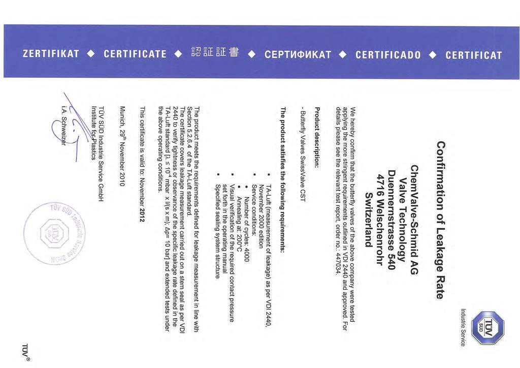
3 Series NKS-C, NKSP-C, NKL-C, NKLP-C Page 3 Relevant documents Declaration of conformity acc. to the EC Pressure Equipment Directive 97/23/EG Confirmation of Leakage Rate (TA-Luft) Form for Safety Information Concerning the Contamination QM _en For NKLP-C or NKSP-C, operating manual for actuator 1 Technical data Manufacturer: Richter Chemie-Technik GmbH Otto-Schott-Str. 2 D Kempen Telephone: +49 (0) Fax: +49 (0) richter-info@idexcorp.com Internet: Designation: Shut-off and control butterfly valve with lug-style and wafer-style Disc/stem unit plastic-lined, stainless steel, Hastelloy or Titanium Certified to Clean Air Act (TA Luft) Strength and tightness (P10, P11) of the pressurebearing body tested to DIN EN Gas-tight (P12) in the seat to DIN EN , leak rate A Flange connecting dimensions: DIN EN , shape B, (ISO type B) PN 10 or ASME B16.5 class 150 (50-24 ) and ASME B16.47 Class 150 (28-40 ) Face to face: DIN EN 558-1, basic series 20 (ISO 5752 series 20) Dimensions and individual parts: See Section 10 Materials: Body material: Ductile cast iron EN-JS 1049 to DIN EN 1563 ( DIN 1693) Lining material: PTFE.../F PTFE modified.../f PTFE modified antistatic /F L Disc/stem unit: PFA-lined.. F PFA-lined antistatic.. L Stainless steel , S Hastelloy C22.. H Titanium Grade 2.. T Temperature range: -20 C to +200 C (-4 F to +400 F) accord. to operating pressure See pressure-temperature diagram in Section Operating pressure: 10 bar (145 psig) DN ) 6 bar (85 psig) DN accord. to operating pressure Options: Polished disc surfaces Weights: See table in Section 1.7 Dimensions and single components: See dimensional drawings in Section 10


4 Series NKS-C, NKSP-C, NKL-C, NKLP-C Page Overview of sizes Series Actuation /F /F-L /F-S /F-H /F-T /F-L-S /F-L-H /F-L-T Body design NKS-C NKSP-C Lever DN 65, 125 2½", 5" Gear DN 65, 125 DN 65, 125, 2½", 5" Actuator 2½", 5", connection to ISO 14"-16" 5211 DN "-8" DN "-12" DN "-8" DN "-12" NKL-C NKLP-C Lever Gear Actuator connection to ISO 5211 DN 65, 125 2½", 5" DN 65, 125, ½", 5", 18"-30" DN 65, 125 2½", 5" DN 65, 125, ½", 5", 14"-24" DN "-8" DN "-40" DN "-8" DN "-24" 1.2 Type codes Series Code NKS-C/F wafer-style body NKS-C NKL-C/F lug-style body NKL-C Body lining Code PTFE F PTFE modified T PTFE modified antistatic TL PTFE modified antistatic FDA TF UHMW-PE E Material disc/stem unit Code PFA lined F PFA lined, antistatic L Stainless steel , S Hastelloy C22 H Titanium Grad 2 T Polished disc surfaces ST Indicate valve size DN 50, 80, 100, 125 2) Flange connection Code ISO PN 10 tapped hole NKL-C 1a Through hole ISO NKL-C 1 ASME B16.5 or B CL150 Tapped hole. NKL-C 2b Through hole ASME NKL-C 2 JIS R K NKL-C 4 No tapped or through holes NKS-C _ NKS-C from DN 350 is NKL-C with through holes ISO NKS-C1 with through holes ASME NKS-C2 Body material Code Ductile cast iron EN-JS 1049 G Stainless steel S C-steel C CF-GF- compound Vinylester V (DN ) Flexible inlay Code Silicon S FKM (Viton or equal) V FDA-FKM F Actuation Code Lever lockable H Worm gear, with hand wheel S 1) Without actuation O Data on name plate Code C/bar C F/psi F Standard 1) Standard up to DN 250 Option 2) In the certificates and Order-related Specification the sizes are spezified in DN (mm) en Revision 01 TM 8176 Edition 03/2011

5 Series NKS-C, NKSP-C, NKL-C, NKLP-C Page 5 Order example NKS-CTLL80 GSHC Order example NKS-C TL L 80 G S H C Series NKSP-C Body lining TL Disc/stem unit L Valve size 80 Flange connection Body material G Flexible inlay S Actuation H Type plate C 1.3 Name plate, CE and body markings The stainless steel name plate is undetachably riveted to the body. If the operator attaches his identification, it must be ensured that the valve matches the application in question. Example of name plate with CE marking: Sign for transport securing device for actuator Body identification : The following are visible on the body according to DIN EN 19 and AD 2000 A4: Nominal size Rated pressure Body material Manufacturer's identification Melt number/foundry identification Cast date
6 Series NKS-C, NKSP-C, NKL-C, NKLP-C Page Tightening torques All screws greased, tighten in diametrically opposite sequence! After the plant has been started up (especially with the first temperature load) the tightening torques must be checked and the correct value set again. The tightening torques for pipe screws and body screws mentioned must not be exceeded. For an exception, see Section 8, flange connection valve/pipe is leaking. The following tightening torques are recommended: Pipe screws, flanges to ISO/DIN Standard threaded hole Flange nom. size Screws Tightening torque [mm] [ISO/DIN] [Nm] 50 4 x M x M x M x M x M x M x M x M x M x M x M x M x M x M x M x M x M x M Pipe screws flanges ISO/DIN drilled to ASME Class 150 Standard threaded hole Flange nom. size Screws Tightening torque [mm] [inch] [ASME] [Nm] [in-lbs] x ⅝ -11UNC ½ 4 x ⅝ -11UNC x ⅝ -11UNC x ⅝ -11UNC " 8 x ¾ -10UNC x ¾ -10UNC x ¾ -10UNC x ⅞ -9UNC x ⅞ -9UNC x 1-8UNC x 1-8UNC " 16 x 1⅛ -7UNC " 20 x 1⅛ -7UNC " 20 x 1¼ -7UNC " 28 x 1¼ -7UNC " 28 x 1¼ -7UNC " 28 x 1½ -7UNC " 32 x 1½ -6UNC " 36 x 1½ -6UNC Pipe screws, flanges to ISO/DIN, through hole NKS-C+NKSP-C from size DN 350 (14") upwards with lug-style body and through hole Flange Tightening Screws nom. size torque [mm] [ISO/DIN] [Nm] 50 4 x x x x x x x x x x x x x x x x x x en Revision 01 TM 8176 Edition 03/2011
7 Series NKS-C, NKSP-C, NKL-C, NKLP-C Page 7 Pipe screws flanges ISO/DIN drilled to ASME Class 150, through hole NKS-C+NKSP-C from size DN 350 (14") upwards with lug-style body and through hole Flange nom. Tightening Through hole size torque [mm] [inch] [mm] [Nm] [in-lbs] x ½ 4 x x x " 8 x x x x x x x " 16 x " 20 x " 20 x " 28 x " 28 x " 28 x " 32 x " 36 x Body screws Hex. socket head screws for lug-style and wafer-style bodies Nom. size Hex. socket Tightening head screw torque [mm] [inch] [ISO/DIN] [Nm] [in-lbs] 50 2 M6x ½ M6x M8x M10x " M10x M10x M12x M12x M16x M16x M16x " M16x " M16x " M16x " M16x " M16x " M20x " M20x " M20x en Revision 01 TM 8176 Edition 03/2011
8 Series NKS-C, NKSP-C, NKL-C, NKLP-C Page Dimensions - Installation Nom. size E 1 T 1 L 2 Connection 3 [mm] [inch] [mm] [mm] [mm] F ½ F F F " F F F F F F F " F " F " F " F " F " F " F " F30 1 See also Section 6.4, paragraph 1 2 Face to face to DIN EN 558-1, series 20 (ISO 5752, series 20) without DN Connections for worm gears and brackets as per DIN ISO 5211 The inside diameter of the mounted pipe flanges must always be greater than the dimension E in the table! For more dimensions, see drawings in Section Flow rate value kv [m³/h] Disc/stem unit PFA-lined Nom. Size Angle of opening [mm] [inch] ½ 4,4 14,0 27,4 49, " 23, " " " " " "
9 Series NKS-C, NKSP-C, NKL-C, NKLP-C Page Disc/stem unit stainless steel, Hastelloy, Titan Nom. Size Angel of opening [mm] [inch] ,9 6,6 13,6 25,2 40, ½ 4,4 14,0 27,4 49, ,4 23,2 43, ,9 52, " 23, , " " " " " " " " Weights (ca. kg) Nom. size Lug style body Sandwichbody [mm] [inch] Open staff end Lever Gear ,0 3,0 0,8 2,0 65 2½ 7,0 4,0 0,8 2, ,1 5,0 0,8 2, ,8 6,3 1,1 2, " 14,5 7,7 1,1 2, ,8 10,0 1,4 4, ,6 16,5 1,9 4, ,3 24,5 -- 4, , , , " , " , " , " , " , " , " , " ,5 Actuator see data of the manufacturer.
10 Series NKS-C, NKSP-C, NKL-C, NKLP-C Page Breakaway torques Nom. size Md erf Md S Md H Md T [mm] [inch] [Nm] [Nm] [Nm] [Nm] ½" " " " " " " " " " Cavitation coefficient z for 75% duty Nom. size at kv/kvs = 75 % [mm] [inch] z , ½" 0, , , " 0, , , , , , , " 0, " 0, " 0, " 0, " 0, " 0, " 0, " 0,40 Md erf = incl. 10% safety Md H = Hastelloy stem Md S = Stainless steel stem Md T = Titanium stem 1.10 Pressure-temperature-diagram When used in the minus temperature range, the regulations applicable in the country in question must be observed en Revision 01 TM 8176 Edition 03/2011
11 Series NKS-C, NKSP-C, NKL-C, NKLP-C Page 11 2 Notes on safety This operating manual contains fundamental information which is to be observed during installation, operation and maintenance. It must therefore be read before installation and commissioning! For valves which are used in potentially explosive areas, see Section 3. Installation and operation are to be performed by qualified staff. The area of responsibility, authority and supervision of the staff must be regulated by the customer. General hazard symbol! People may be put at risk. Safety symbol! The ball valve and its function may be put at risk if this safety symbol is not observed. It is imperative to observe warnings and signs attached directly to the ball valve and they are to be kept fully legible. Non-observance of the notes on safety may result in the loss of any and all claims for damages. For example, non-observance may involve the following hazards: Failure of important functions of the valve/plant. Risk to people from electric, mechanical and chemical effects. Risk to the environment through leaks of hazardous substances. 2.1 Intended use Shut-off and control butterfly valves are pressuremaintaining components in accordance with the German Pressure Equipment Directive (DGRL) for the passage and shut-off of fluids. The valves are suitable for vapours, gases and liquids of group 1 according to the DGRL and have a corrosion-resistant plastic lining. The field of application for the shut-off and control butterfly valves include: Light and medium corrosive, pure and slightly solids-laden liquids, vapours and gases Materials in contact with the medium which are FDA-compliant can be used for food and pharmaceutical feedstock as well as in biochemistry. Powdered and granulated non or low abrasive solids Shut-off and control butterfly valves with a plasticlined disc/stem unit are used for highly aggressive, corrosive media. Shut-off and control butterfly valves with a stainless steel disc/stem unit are suitable for less aggressive media, are cheaper and beneficial for thorough valve cleaning. With both body designs the butterfly valves can be installed as a wafer-style valve (sandwich-type butterfly valve). Product features: Wide sealing surfaces of the body lining Long valve neck for optimum heat insulation Maintenance-free, self-adjusting stem seal Leak-proof to the atmosphere in accordance with the German Clean Air Code Solids can lead to increased wear, leaks, damage to sealing surfaces or to a reduction in the service life of the valve. In case of the valve is intended for operating data other than those intended, the customer must carefully examine whether the design of the valve, accessories and materials are suitable for the new application (consult the manufacturer). 2.2 For the customer / operator If a safety valve is used, the operator must ensure that actuators which are retrofitted are adapted to suit the valve hot or cold valve parts are protected by the customer against being touched the valve has been properly installed in the pipe system the operating conditions stipulated in the data sheet are not exceeded in continuous operating mode. This is not the manufacturer's responsibility. Butterfly valves which are used as end valves must be sealed with a blind flange at the free connection end and appropriately secured against unauthorized activation. Loads caused by earthquakes were not allowed for in the design. Fire protection to DIN EN ISO is not possible (plastic lining and plastic components). 2.3 Improper operation The operational reliability of the valve supplied is only guaranteed if it is used properly in accordance with Section 2.1 of this operating manual. The operation limits specified on the identification plate and in the pressure-temperature diagram must under no circumstances be exceeded.
12 Series NKS-C, NKSP-C, NKL-C, NKLP-C Page 12 3 Safety notes for applications in potentially explosive areas based on the Directive 94/9/ EC (Atex 95) The valves are intended for use in a potentially explosive area and are therefore subject to the conformity assessment procedure of the directive 94/9/EC (ATEX). As part of this conformity assessment, an ignition hazard analysis to EN to satisfy the fundamental safety and health requirements was conducted with the following result: The valves do not have any ignition source of their own and can be operated both manually as well as mechanically/electrically. The valves are not covered by the scope of application of the ATEX directive and therefore do not need to be identified accordingly. The valves may be used in a potentially explosive area. Supplementary notes: Electric/mechanical actuators must be subjected to their own conformity assessment to ATEX. It is imperative to observe the individual points of intended use for application in a potentially explosive area. 3.1 Intended use Inadmissible modes of operation, even for brief periods, may result in serious damage to the unit. In connection with explosion protection, potential sources of ignition (overheating, electrostatic and induced charges, mechanical and electric sparks) may result from these inadmissible modes of operation; their occurrence can only be prevented by adhering to the intended use. Furthermore, reference is made in this connection to the Directive 95/C332/06 (ATEX 118a) which contains the minimum regulations for improving the occupational health and safety of the workers who may be at risk from an explosive atmosphere. A difference is made between two cases for the use of chargeable liquids (conductivity <10-8 S/m): 1. Chargeable liquid and non-conductive lining Charges can occur on the lining surface. As a result, this can produce discharges inside the valve. However, these discharges cannot cause ignitions if the valve is completely filled with medium. If the valve is not completely filled with medium, e.g. during evacuation and filling, the formation of an explosive atmosphere must be prevented, e.g. by superimposing a layer of nitrogen. It is recommended to wait 1 hour before removing the valve from the plant in order to permit the elimination of static peak charges. This means that, to safely prevent ignitions, the valve must be completely filled with medium at all times or else a potentially explosive atmosphere must be excluded by superimposing a layer of inert gas. 2. Chargeable liquid and conductive lining No hazardous charges can occur as charges are discharged direct via the lining and shell (surface resistance <10 9 Ohm, leakage resistance <10 6 Ohm). Static discharges of non-conductive linings are only produced through the interaction with a non-conductive medium and are therefore the responsibility of the plant operator. Static discharges are not sources of ignition which stem from the valves themselves! The temperature of the medium must not exceed the temperature of the corresponding temperature class or the maximum admissible medium temperature as per the operating manual. If the valve is heated (e.g. heating jacket), it must be ensured that the temperature classes prescribed in the Annex are observed. To achieve safe and reliable operation, it must be ensured in inspections at regular intervals that the unit is properly serviced and kept in technically perfect order Increased wear to the valve can be expected with the conveyance of liquids containing abrasive constituents. The inspection intervals are to be reduced compared with the usual times. Actuators and electric peripherals, such as temperature, pressure and flow sensors etc., must comply with the valid safety requirements and explosion protection provisions. The valve must be grounded. This can be achieved in the simplest way via the pipe screws using tooth lock washers. Otherwise grounding must be ensured by other action, e.g. cable bridges. Attachments such as actuators, position controllers, limit switches etc. must satisfy the relevant safety regulations as regards explosion protection and, if required, be designed in compliance with ATEX. Special attention must be paid to the appropriate safety and explosion protection notes in the respective operating manuals. Plastic-lined valves must not be operated with carbon disulphide.
13 Series NKS-C, NKSP-C, NKL-C, NKLP-C Page 13 4 Safety note for valves, certified to Clean Air Act (TA-Luft) On request, this valve can be supplied compliant with the German Clean Air Code. Certificate / Manufacturer Declaration Validity is dependent on the operating instructions being read and observed. In particular, servicing must be conducted at regular intervals, and the bolted connections relevant for tightness must be inspected and retightened if necessary. 5 Transport, storage and disposal It is imperative, for all transport work, to observe generally accepted engineering practice and the accident prevention regulations. Handle the goods being transported with care. During transport the valve must be protected against impacts and collisions. Directly after receipt of the goods, the consignment must be checked for completeness and any in-transit damage. Do not damage paint protection. 5.1 Storage If the valve is not installed immediately after delivery, it must be put into proper storage. It should be stored in a dry, vibration-free and wellventilated room at as constant a temperature as possible. Elastomers are to be protected against UV light. In general, a storage period of 10 years should not be exceeded. It is not permitted to put the valve into store with the disc completely closed or with an opening angle greater than Return consignments Valves which have conveyed aggressive or toxic media must be well rinsed and cleaned before being returned to the manufacturer's works. It is imperative to enclose a safety information sheet / general safety certificate on the field of application with the return consignment. Pre-printed forms are enclosed with the installation and operating manual. Safety precautions and decontamination measures are to be mentioned. 5.4 Transport securing device 5.2 Transport preparations During transport the disc/stem unit must not project beyond the body dimensions. Hand lever: When the valve is in the closed position, the lever is to lock in the first lever catch. This results in the disc/stem unit being slightly opened. Worm gear When the valve is in the closed position, the disc/stem unit is to be open. Actuator When the valve is in the closed position, the disc/stem unit is to be open. Attach a locking plate on shut-off and control butterfly valves with a single-acting actuator. See also Section and the drawing in Section 5.4. Mount flange caps.
14 Series NKS-C, NKSP-C, NKL-C, NKLP-C Page Disposal Parts of the valve may be contaminated with medium which is detrimental to health and the environment and therefore cleaning is not sufficient. Risk of personal injury or damage to the environment due to the medium! Wear protective clothing when work is performed on the valve. Prior to the disposal of the valve: Collect any medium, etc. which has escaped and dispose of it in accordance with the local regulations. Neutralize any medium residues in the valve. Separate valve materials (plastics, metals etc.) and dispose of them in accordance with the local regulations. 6 Installation Examine valve for in-transit damage, damaged diaphragm valves may not be installed. Before installation the valve and the connecting pipe must be carefully cleaned to remove any dirt, especially hard foreign matter. During installation, pay attention to the correct tightening torque, aligned pipes and tension-free assembly. Ensure that a remotely actuated actuator cannot be accidentally switched on. 6.1 Installation possibilities Series NKS-C wafer-style body They are used for sandwich installation. The valve is clamped between the two pipes. From DN 350 upwards a lug-style body with through holes is standard Series NKL-C lug-style body They are suitable as an intermediate flange and deadend valve. On request, through holes can also be provided instead of the tapped bores. 6.2 Flange caps and gaskets Leave the original packaging on the valve until immediately before installation. NKS-C with TFM body lining does not need any gaskets. If plastic sealing surfaces can be damaged, e.g. by mating flanges made of metal or enamel, use PTFElined gaskets with a metal inlay. 6.3 Direction of flow and installation position Except solids-containing liquids: With solid containing media butterfly valves are preferably installed with horizontally positioned stem and bottom half of disc opening into flow direction. 6.4 Installation Can the disc open in the pipeline? For dimensions see Section 1.5. Is the disc open 10 15? Mount butterfly valve and gaskets centrically. Tighten the piping bolts crosswise and hand-tight. By means of a test actuation ensure that the disc is able to freely rotate. With the disc slightly opened, tighten the piping bolts crosswise. For the torques see Section 1.4. Butterfly valves which are used as end valves must be sealed with a blind flange at the free connection end and appropriately secured against unauthorised activation Additional advice for shut-off and control butterfly valve with actuator For single-acting actuators a locking plate has been fitted into the bracket, blocking the stem at a disc opening of Remove the locking plate before the first test actuation, screw in again hex. screw 901/1. Slightly actuate the actuator. Please pay attention to the drawing in Section Earthing On request, the butterfly valves are supplied with an earthing connection. Installation is independent of the direction of flow. Any fitting position can be chosen.
15 Series NKS-C, NKSP-C, NKL-C, NKLP-C Page 15 7 Operation 7.1 Initial commissioning Normally, the valves have been tested for leaks with air or water. Prior to initial operation check body bolting. For torques see Section 1.4. Unless otherwise agreed, there could be residual amounts of water in the flow section of the valve; this could result in a possible reaction with the medium. To prevent leaks, all connection screws should be retightened after the initial loading of the valve with operating pressure and operating temperature. For torques see Section Improper operation and their consequences Do not operate the butterfly valve without valve actuation. Otherwise the disc will be uncontrollably set in motion by the medium flow. Butterfly valves with a hand lever should never be abruptly opened or closed. This can lead to water hammer effects. Dissipate thermal expansion volumes in shut-off pipes. If the plastic swells up due to the effect of the medium, this can result in the functional parts jamming. Operation with solids leads to increased wear. There must be no foreign matter on the sealing surfaces. Operation during cavitation leads to increased wear. Non-observance of the pressure-temperature diagram can lead to damage of the plastic lining. If no monitoring is provided by the warning connection, do not tighten safety stuffing box. Otherwise any leak cannot be seen. Do not apply heavy loads to the lever; the lever or butterfly valves may be damaged. Do not use a lever extension as this could cause damage. 7.3 Shutdown Before loosening the flange bolts: ensure plant to be free of pressure flush out medium observe safety regulations Prior to starting any repair work, the valve is to be thoroughly cleaned. Even if the valve has been properly emptied and rinsed, residual medium may still be found in the valve, In addition to suitable protective clothing, wear working gloves and goggles for assembly and maintenance work. After dismantling, immediately protect the valve flanges against mechanical damage with flange caps. See also Section Additional advice for shut-off and control butterfly valve with actuator Ensure that a remotely actuated quarter-turn actuator cannot be accidentally switched on. Having dismounted the valve, mount the locking plate 507 and screw in with hex. screw 901/1. See also Section and drawing in Section 5.4.
16 Series NKS-C, NKSP-C, NKL-C, NKLP-C Page 16 8 Malfunctions Flange connection ball valve/pipe is leaking Retighten the flange screws to a tightening torque according to Section 1.3. If this does not remedy the leak, the recommended torques may be exceeded by 10%. If this also fails to stop the leak, dismantle and inspect the ball valve. Dismount and inspect the valve. Stem passage leaking With no safety stuffing box: Dismount valve and repair. With safety stuffing box: First of all, the packing gland follower can be tightened. For torques see Section 1.3. Then dismount the valve as quickly as possible and repair. Medium leaking at the partition between lower and upper halves Dismont valve and repair, probably the stem seal is not tight. Valve does not switch Has the locking plate been dismounted? See Section 5.4. Is the actuator supplied with power? Has a directional control valve been correctly connected? Is there foreign matter in the valve? The bore of the valve is leaking Wear at the valve actuation? Do limit stops have to be adjusted? Is the shaft deformed? Deformation, damage or wear to body lining or disc? 9 Maintenance All repair work is to be performed by qualified personnel using the appropriate tools. For the arrangement, designation and item numbers of all parts of the valve, see Section 10. Spare parts are to be ordered with all the details in acc. with the valve identification. Only original spare parts may be installed. To prevent leaks, a regular check of the connection screws should be made in line with the operating requirements. For torques see Section 1.4. When disassembling and assembling the valve, attention is to be paid to the tables and drawings in Section 1 and 10. As the body lining 409 is drawn over the disc/stem unit 221 while warm, this work should only be carried out by the manufacturer. Has the pump been shut down, drained and flushed according to the regulations? See also Section 7.3. If assembled incorrectly, individual components of the valve may be damaged and this can result in malfunctions during operation. 9.1 Notes for assembly The flexible inlay 521 expands during assembly. Do not cut off the overhang, but push back into the lower and upper part of the shell 120. Before tightening the body screws 914/1 align the disc/stem unit 221 centrally in the closed position. Mark the position of the disc/stem unit 221 against body lining 409 at the hub, so permitting switching only to this point during later test switching. With disc/stem unit in closed position, tighten the body screws (914/1, as well 918/1 and 929/2) until the gap between the upper and lower part of the shell 120 is ca. 5 mm. Open the valve several times counterclockwise (when viewing the stem unit) and close again in the opposite direction. A sealing edge can form in this way. Never switch in the other direction of rotation over the sealing edge! Tighten the body bolts 1-2 mm when disc in closed position. Repeat the previously described process once or twice. When finally tightening the body bolts, pay attention to the torques provided in Section 1.4.
17 Series NKS-C, NKSP-C, NKL-C, NKLP-C Page Valve actuation The disc/stem unit has a 2-surface pivot point on DN (2"- 6") and a 4-surface pivot point on DN (8"- 40") for mounting a hand lever or coupling. Hand lever or 2/4-surface pivot point parallel to the pipe axis: Valve open Hand lever or 2/4-surface pivot point at right angles to the pipe axis: Valve closed In the case of a coupling, 2 red marks indicate the position of the disc on them. Marks parallel to the axis of the pipeline: Valve open Marks at right angles to the axis of the pipeline: Valve closed Required breakaway torque The breakaway torque of the actuator must be at least as high as the breakaway torque of the butterfly valve, about 20% higher being better however. Media of higher viscosity and/or those with solids may require an increased factor of safety when calculating the size of the actuator. This is particularly true for non-newtonian fluids such as high polymer substances, suspensions, pastes, lubricants, resins, lacquers etc. Admissible factors of safety lie in the range of 20-50% of the breakaway torque. To prevent damage to the valve, particular attention must be paid to the torque Mdmax in Section Actuated with lever The throttling plate 519 permits a fixing of the lever at 10 intervals. It is lockable with a commercially available padlock Actuated by means of worm gear In the standard version, the manufacturer normally provides worm gears with a special pick-up for the stem pivot. The bracket and the coupling are thereby not required. 9.3 Tests Following tests would be done after the assembly. Measurement of the breakaway torque The breakaway torque required for opening and closing the valve is to be ascertained. The maximum torque should not exceed the values given in Section 1.8. Tightness of valve opening and shaft bushing The completed valves have to undergo a leak test of the closure with air Remotely actuated Richter butterfly valves can be remotely actuated by means of pneumatic, hydraulic or electric quarter-turn actuators equipped with a connection as per DIN EN ISO Couplings and brackets are available as accessories in the Richter range of products.
18 Series NKS-C, NKSP-C, NKL-C, NKLP-C Page Drawings 10.1 Legend 120 shell 221 disc/stem unit 313/x bearing and pressure package 409 body lining 521 flexible inlay 532 grounding rope 914/1 hex. socket screw 936/1 toothed lock washer Lever unit 235 lever assembly 519 throttling plate Worm gear 857 worm gear Actuator 510 bracket 804 coupling 850 actuator 10.2 Sectional drawing NKS-C Wafer-style body with hand lever
19 Series NKS-C, NKSP-C, NKL-C, NKLP-C Page Sectional drawing NKL-C Lug-style body with hand lever 10.4 Worm gear
20 Series NKS-C, NKSP-C, NKL-C, NKLP-C Page Actuator 10.6 Connection actuator Connection flange to ISO surface pivot point 4-surface pivot point DN ǾD A ǾS SW ǾS SW ǾP T [mm] [inch] [mm] ,5 65 2½" , , , " , , , , , , , " , " , " , " , " , " , " , " ,5
21 Series NKS-C, NKSP-C, NKL-C, NKLP-C Page Dimensional drawing NKS-C with hand lever DN H1 h B l L D øc E [mm] [inch] [mm] ½" " " " Only with " " worm gear " " " "
22 Series NKS-C, NKSP-C, NKL-C, NKLP-C Page Dimensional drawing NKS-C with worm gear DN H1 B L D ǾC E p Ǿk r s t c e b [mm] [inch] [mm] , ,7 43,5 67,5 65 2½" , ,7 43,5 67, , ,7 43,5 67, , ,7 43,5 67, " , ,7 43,5 67, ,5 81, ,5 81, ,5 81, , ,5 90, ,5 68, " From DN 350 (14 ) " Lug-style body NKL-C with through holes " " " " " "
23 Series NKS-C, NKSP-C, NKL-C, NKLP-C Page Dimensional drawing NKSP-C
24 Series NKS-C, NKSP-C, NKL-C, NKLP-C Page 24 Table NKSP-C DN H1 B L D ǾC E ISO 5211 H2 H3 H4 L1 L2 L3 L4 [mm] [inch] [mm] ½" F " F F " " From DN 350 (14 ) F " Lug-style body NKL-C with " through holes F " " F " " F See manufacturer s information on the dimensions for the actuator.
25 Series NKS-C, NKSP-C, NKL-C, NKLP-C Page Dimensional drawing NKL-C with hand lever DN H1 h B l L D øc E [mm] [inch] [mm] ½" " " " Only with " worm gear " " " " "
26 Series NKS-C, NKSP-C, NKL-C, NKLP-C Page Dimensional drawing NKL-C with worm gear DN H1 B L D ǾC E p Ǿk r s t c e b [mm] [inch] [mm] , ,7 43,5 67,5 65 2½" , ,7 43,5 67, , ,7 43,5 67, , ,7 43,5 67, " , ,7 43,5 67, ,5 81, ,5 81, ,5 81, , ,5 90, ,5 68, , ,5 90, ,5 68, , ,5 90, ,5 68, " " " , , " , , " , , " , , " , , " , ,5 186
27 Series NKS-C, NKSP-C, NKL-C, NKLP-C Page Dimensional drawing NKLP-C
28 Series NKS-C, NKSP-C, NKL-C, NKLP-C Page 28 Table NKLP-C/F DN H1 B L D ǾC E ISO 5211 H2 H3 H4 L1 L2 L3 L4 [mm] [inch] [mm] ½" F " F F " " F " " F " " F " " F See manufacturer s information on the dimensions for the actuator.
29 ChemValve-Schmid AG Duennernstrasse 540 CH-4716 Welschenrohr Konformitätserklärung nach EN ISO//IEC Declaration of Conformity according to EN ISO//IEC Produkt Product Bauart Design Baureihe Serie PTFE-Absperrklappe PTFE Lined Butterfly Valve Absperr- und Regelklappe Shut-off and control butterfly valve NKL-C, NKS-C Nennweite DN 50 bis DN 1000, 2 bis 40 Size DN 50 to DN 1000, 2 to 40 Seriennummer ab/from Series number EU-Richtlinie 97/23/EG Druckgeräterichtlinie 97/23/EC Pressure Equipment Directive EU-Directive 2006/42/EG 1) Maschinenrichtlinie 2006/42/EC 1) Machinery Directive Angewandte DIN EN 593 Technische Spezifikation AD 2000 Applied Technical Specification DIN EN ISO Überwachungsverfahren Surveillance Procedure Konformitätsbewertungsverfahren 97/23/EG Conformity assessment procedure 97/23/EC 97/23/EG Zertifizierungsstelle für Druckgeräte der TÜV Süd Industrie Service GmbH Notified Body 0036 Modul A1 / Modul B+C1 Kennzeichnung 97/23/EG 97/23/EC ) Marking 2006/42/EG 1) 2006/42/EC 1) 0036 Das Unternehmen ChemValve-Schmid AG bescheinigt hiermit, dass die o.a. Baureihen die grundsätzlichen Anforderungen der aufgeführten Richtlinien und Normen erfüllt. ChemValve-Schmid AG confirms that the basic requirements of the above specified directives and standards have been fulfilled. 1) Alle Armaturen, mit Ausnahme der Armaturen mit Handbetätigung. For all valves, with exceptions to valves with hand operation Welschenrohr, B. Schmid Ch. Schmid Schnyder Geschäftsführer, Leiter Forschung & Entwicklung Leiter Qualitätsmanagement Managing Director, Manager Research & Dvelopment Quality Manager
30
31 Safety Information / Declaration of No Objection Concerning the Contamination of Richter-Pumps, -Valves and Components 1 SCOPE AND PURPOSE Each entrepreneur (operator) carries the responsibility for the health and safety of his employees. This extends also to the personnel, who implements repairs with the operator or with the contractor. Enclosed declaration is for the information of the contractor concerning the possible contamination of the pumps, valves and component sent in for repair. On the basis of this information for the contractor is it possible to meet the necessary preventive action during the execution of the repair. Note: The same regulations apply to repairs on-site. 2 PREPARATION OF DISPATCH Before the dispatch of the aggregates the operator must fill in the following declaration completely and attach it to the shipping documents. The shipping instructions indicated in the respective manual are to be considered, for example: Discharge of operational liquids remove filter inserts lock all openings hermetically proper packing Dispatch in suitable transport container Declaration of the contamination fixed outside!! on the packing Prepared: CRQ/Lam on: Feb. 15, 06 Page: 1 QM No.: _en/4-06 Approved: CRQ/Zu on: Feb. 15, 06 of : 2

32 Declaration about the Contamination of Richter Pumps, -Valves and Components The repair and/or maintenance of pumps, valves and components can only be implemented if a completely filled out declaration is available. If this is not the case, delay of the work will occur. If this declaration is not attached to the devices, which have to be repaired, the transmission can be rejected. Every aggregate has to have it s own declaration. This declaration may be filled out and signed only by authorized technical personnel of the operator. Contractor/dep./institute : Reason for transmitting Please mark the applicable Repair: subject to fee Warranty Street : Exchange: subject to fee Warranty Postcode, city: Exchange/ Replacement already initiated/received Contact person: Return: Leasing Loan for credit note Phone : Fax : End user : A. Details of Richter-product: Failure description: Classification: Article number: Equipment: Serial number: Application tool: Application process: B. Condition of the Richter-product: no 1) yes no Contamination : no 1) yes Was it in operation? toxic Drained (product/operating supply item)? caustic All openings hermetically locked! inflammable Cleaned? explosive 2) If yes, with which cleaning agent: mikrobiological 2) and with which cleaning method: radioactive 3) 1) if "no", then forward to D. other pollutant 2) Aggregates, which are contaminated with microbiological or explosive substances, are only accepted with documented evidence of an approved cleaning. 3) Aggregates, which are contaminated with radioactive substances, are not accepted in principle. C. Details of the discharged materials (must be filled out imperatively) 1. With which materials did the aggregate come into contact? Trade name and/or chemical designation of operational funds and discharged materials, material properties, e.g. as per safety data sheet (e.g. toxic, inflammable, caustic) X Trade name: Chemical designation: a) b) c) d) no yes 2. Are the materials specified above harmful to health? 3. Dangerous decomposition products during thermal load? If yes, which ones? D. Mandatory declaration: We assure that the data in this explanation are truthful and complete and as a signatory I am able to form an opinion about this. We are aware that we are responsible towards the contractor for damages, which results from incomplete and incorrect data. We commit ourselves to exempt the contractor from claims for damages of thirds resulting from incomplete or incorrect data. We are aware that we are directly responsible towards thirds, irrespective of this declaration, which belongs in particularly to the employees of the contractor consigned with the handling repair of the product. Name of the authorized person (in block letters): Date Signature Company stamp Prepared: CRQ/Lam on: Feb. 15, 06 Page: 2 QM No.: _en/4-06 Approved: CRQ/Zu on: Feb. 15, 06 of : 2
33 FAX Fax No. () Pages (incl. cover sheet) () To: () Contact person: Reference: Extension: Address: Date: () () - () () () Your order No.: () Our Kom. No.: () Serial No.: () Dear Sirs, The compliance with laws for the industrial safety obligates all commercial enterprises to protect their employees and/or humans and environment against harmful effects while handling dangerous materials. The laws are such as: the Health and Safety at Work Act (ArbStättV), the Ordinance on Harzadous Substances (GefStoffV, BIOSTOFFV), the procedures for the prevention of accidents as well as regulations to environmental protection, e.g. the Waste Management Law (AbfG) and the Water Resources Act (WHG) An inspection/repair of Richter products and parts will only take place, if the attached explanation is filled out correctly and completely by authorized and qualified technical personnel and is available. In principle, radioactively loaded devices sent in, are not accepted. Despite careful draining and cleaning of the devices, safety precautions should be necessary however, the essential information must be given. The enclosed declaration of no objection is part of the inspection/repair order. Even if this certificate is available, we reserve the right to reject the acceptance of this order for other reasons. Best regards RICHTER CHEMIE-TECHNIK GMBH Enclosures () Landesbank Rheinland-Pfalz, Mainz Kto (BLZ ) SWIFT: MALA DE USt. Id. Nr. DE Sitz der Gesellschaft: Kempen Amtsgericht Krefeld HRB 9635 Geschäftsführer: Dipl.-Ing. Günter Naasner QM-Nr.: an_en/4-01
Sampling Valves PFA-lining or investment cast stainless steel
 INSTALLATION AND OPERATING MANUAL Series PA/F, PA/S Sampling Valves PFA-lining or investment cast stainless steel Keep for future use! This operating manual must be strictly observed before transport,
Control Ball Valve with V-control ball/stem unit and Richter ENVIPACK universal packing
 INSTALLATION AND OPERATING MANUAL Series KNR/F, KNRP/F KNR-D/F, KNRP-D/F Control Ball Valve with V-control ball/stem unit and Richter ENVIPACK universal packing Keep for future use! This operating manual
Ball Valve with ball, stem and Richter ENVIPACK universal packing
 INSTALLATION AND OPERATING MANUAL Series KN/F, KNP/F, KN-D/F, KNP-D/F Ball Valve with ball, stem and Richter ENVIPACK universal packing Keep for future use! This operating manual must be strictly observed
Diaphragm Shut-off and Control Valves
 INSTALLATION AND OPERATING MANUAL Series MV/F, MVM/F, MVP/F, MVMP/F Diaphragm Shut-off and Control Valves Keep for future use! This operating manual must be strictly observed before transport, installation,
Ball Valve to ASME with ball, stem and Richter ENVIPACK universal packing
 INSTALLATION AND OPERATING MANUAL Series KNA/F, KNAP/F KNA-D/F, KNAP-D/F KNA-S/F, KNAP-S/F Ball Valve to ASME with ball, stem and Richter ENVIPACK universal packing Keep for future use! This operating
Series BVI/F, BVIP/F Standard Ball Valve with ball/stem unit or ball and stem, cone shape stem sealing
 INSTALLATION AND OPERATING MANUAL Series BVI/F, BVIP/F Standard Ball Valve with ball/stem unit or ball and stem, cone shape stem sealing Keep for future use! This operating manual must be strictly observed
Ball Valve with ball/stem unit or ball and stem and Richter ENVIPACK universal packing
 INSTALLATION AND OPERATING MANUAL Series KN/F, KNP/F, KN-D/F, KNP-D/F Ball Valve with ball/stem unit or ball and stem and Richter ENVIPACK universal packing Keep for future use! This operating manual must
Standard Ball Valve to ASME with ball/stem unit or ball and stem, cone shape stem sealing
 INSTALLATION AND OPERATING MANUAL Series BVA/F, BVAP/F Standard Ball Valve to ASME with ball/stem unit or ball and stem, cone shape stem sealing WARNING All RICHTER products are designed and manufactured
Installation, Operation, and Maintenance Manual
 Industrial Process Installation, Operation, and Maintenance Manual Series PBV Plastic Lined Ball Valve Table of Contents Table of Contents Introduction and Safety...2 Safety message levels...2 User health
Installation, Operation, and Maintenance Manual
 Industrial Process Installation, Operation, and Maintenance Manual Series PBFV Plastic Lined Butterfly Valve - Lug and Wafer Style Table of Contents Table of Contents Introduction and Safety...2 Safety
Diaphragm Shut-off and Control Valves
 INSTALLATION AND OPERATING MANUAL Series MV/F, MVM/F, MVP/F, MVMP/F Diaphragm Shut-off and Control Valves Keep for future use! This operating manual must be strictly observed before transport, installation,
Richter PFA/PTFE Shut-off and Control Butterfly Valves
 Richter PFA/PTFE Shut-off and Control Butterfly Valves NK, NKS, NKL, NKS-C, NKL-C New: Sizes to mm (4 ) Titanium, PE-UMW Body lining PTFE, TFM-PTFE, PTFE-L, PE-UMW Disc/stem unit PFA, PFA-L, stainless
Mechanical seals external, single or double type Crane 58U 58U
 Series RSA INSTALLATION AND OPERATING MANUAL Translation of the original manual Mechanical seals external, single or double type Crane 58U 58U Keep for future use! This operating manual must be strictly
INSTALLATION AND OPERATING MANUAL Translation of the original manual. Series SCK. Mechanical Seal. double, to DIN EN Keep for future use!
 Series SCK INSTALLATION AND OPERATING MANUAL Translation of the original manual Mechanical Seal double, to DIN EN 12756 Keep for future use! This operating manual must be strictly observed before transport,
Richter PFA/PTFE Shut-off and Control Butterfly Valves
 Richter PFA/PTFE Shut-off and Control Butterfly Valves NK, NKS, NKL, NKS-C, NKL-C New: Sizes to 4 ( mm) Titanium, PE-UMW Body lining PTFE, TFM-PTFE, PTFE-antistatic, PE-UMW Disc/stem unit PFA, PFA-antistatic,
INSTALLATION AND OPERATING MANUAL WARNING. Keep for future use!
 INSTALLATION AND OPERATING MANUAL Series KNA/F, KNAP/F, KNA-D/F, KNAP-D/F KNA-S/F, KNAP-S/F Ball Valve to ASME with ball/stem unit or Al 2 O 3 -ball and stem and Richter ENVIPACK universal packing, full
SUPPLEMENTARY INSTALLATION AND OPERATING MANUAL Translation of the original manual. Series MNK-X, MNK-XB, SCK-X Frame-mounted Chemical Vortex Pumps
 SUPPLEMENTARY INSTALLATION AND OPERATING MANUAL Translation of the original manual Series MNK-X, MNK-XB, SCK-X Frame-mounted Chemical Vortex Pumps Keep for future use! This operating manual must be strictly
Series MNK-X, MNK-XB, SCK-X Frame-mounted Chemical Vortex Pumps
 SUPPLEMENTARY INSTALLATION AND OPERATING MANUAL Translation of the original manual Series MNK-X, MNK-XB, Frame-mounted Chemical Vortex Pumps Keep for future use! This operating manual must be strictly
Declaration of Conformity as per Directive 97/23/EC
 Declaration of Conformity as per Directive 97/23/EC The manufacturer declares that:, 47906 Kempen, Germany PTFE-lined Rotary plug valves Series 23e, with packing with lever for 90 operation with worm gear
Operating Instructions Garlock Butterfly Valves DN : mm / 2-24
 Operating Instructions Garlock Butterfly Valves DN : 50-600 mm / 2-24 PN : 10 / 16 Type: GAR-SEAL SAFETY-SEAL STERILE-SEAL MOBILE-SEAL Conformity declaration... 14 0 Introduction... 15 1 Proper use...
Storage, operating and maintenance instructions for AZ plug valves and Standard valves
 ARMATUREN Plug - Valves metallic with PTFE Sleeve 2-7 way Storage, operating and maintenance instructions for AZ plug valves and Standard valves Plug - Valves FEP/PFA - lined, 2-3 way Butterfly - Valves
Mechanical seals external, single or double type Crane 58U 58U
 INSTALLATION AND OPERATING MANUAL Translation of the original manual Series RSA, RSI Mechanical seals external, single or double type Crane 58U 58U Keep for future use! This operating manual must be strictly
Richter Ball Control Valves Torque transmission free of play
 Richter Ball Control Valves Torque transmission free of play ISO/DIN, ASME/ANSI Lining PFA, optionally PFA-P, PFA-HP, PFA-L k vs 0.1-400 ENVIPACK seal maintenance-free Heavy-duty ball control valves with
These installation and maintenance instructions must be read in full and completely understood before the installation!
 These installation and maintenance instructions must be read in full and completely understood before the installation! 1. General information on the installation and maintenance instructions These instructions
Richter Ball Control Valves Torque transmission free of play
 Richter Ball Control Valves Torque transmission free of play KNAR, KNR, KNARP, KNRP ASME/ANSI, ISO/DIN Lining PFA, optionally PFA-P, PFA-HP, PFA-L Cv 0.12-470 (k vs 0.1-400) Maintenance-free ENVIPACK stem
HEAVY-DUTY BALL VALVES
 HEAVY-DUTY BALL VALVES SHUT-OFF, CONTROL & DRAIN VALVES KN, KNA, KNR, KNAR, KA-N, KK SUPERIOR CORROSION RESISTANCE RELIABLE DESIGN MAINTENANCE-FREE ENVIPACK STEM SEALING -60 TO +200 C (-75 TO +400 F) KN,
T R A N S L A T I O N Declaration of Conformity as per Directive 2014/68/EU
 T R A N S L A T I O N Declaration of Conformity as per Directive 2014/68/EU The manufacturer declares that: Pfeiffer Chemie-Armaturenbau GmbH, 47906 Kempen, Germany PFA/PTFE-lined ball valves BR20a, BR20b,
T R A N S L A T I O N Declaration of Conformity as per Directive 2014/68/EU
 T R A N S L A T I O N Declaration of Conformity as per Directive 2014/68/EU The manufacturer declares that: Pfeiffer Chemie-Armaturenbau GmbH, 47906 Kempen, Germany Butterfly valves BR14a, BR14b, BR14b-Type
Richter Ball Control Valves Torque transmission free of play
 Richter Ball Control Valves Torque transmission free of play KNR KNAR KNR, KNAR, KNRP, KNARP KNR KNAR ISO/DIN, ASME/ANSI Lining PFA, optionally PFA-L, PFA-HP k vs 0.1-400 Maintenance-free ENVIPACK stem
BR 10a Control and Shut-off Butterfly valve
 M-PTFE lined double-eccentric BR 10a Control and Shut-off Butterfly valve Application: Tight-closing, double-eccentric butterfl y control valve with M-PTFE lining for process engineering and plants with
NEOTECHA NEOSEAL BUTTERFLY VALVE INSTALLATION AND MAINTENANCE INSTRUCTIONS
 Before installation these instructions must be fully read and understood 2 SAFETY Please also read through these notes carefully. 2.1 General potential danger due to: a. Failure to observe the instructions
NEOTECHA NTB-NTC BALL VALVES INSTALLATION AND MAINTENANCE INSTRUCTIONS
 Before installation these instructions must be fully read and understood 2 SAFETY Please also read through these notes carefully. 2.1 General potential danger due to: a. Failure to observe the instructions
Operating Instructions: Hand-operated, PTFE-lined butterfly valves, Series 22/23
 0 Introduction These instructions are intended to assist users of BRAY PTFE-lined butterfly valves, Series 22/23 in fitting, operating and servicing valves. Risks may arise and the manufacturer's warranty
Company Standard Mounting Instructions for Type Valves with Type AT Actuator
 Mounting Instructions for Type 72 82-62 Valves with Type AT Actuator Introduction These installation instructions contain important information on the installation, functioning, maintenance and storage
Safety Valves with certification
 INSTALLATION AND OPERATING MANUAL SERIES KSE/F, KSE-C/F Safety Valves with certification spring-loaded Keep for future use! This operating manual must be strictly observed before transport, installation,
Mounting and Operating Instructions EB 8222 EN. Type 3310/AT and Type 3310/3278 Pneumatic Control Valves. Type 3310 Segmented Ball Valve
 Type 3310/AT and Type 3310/3278 Pneumatic Control Valves Type 3310 Segmented Ball Valve Fig. 1 Type 3310/3278 with positioner Fig. 2 Type 3310/AT Mounting and Operating Instructions EB 8222 EN Edition
Richter Sampling Valves
 Richter Sampling Valves PA/F, PA/S Body ductile iron with PFA lining or investment cast stainless steel Bellows-sealed Safety packing gland Representative sampling Richter sampling valves Fields of application
Garlock Butterfly Valves Technical Catalog Trusted throughout the chemical, petrochemical & many other industries
 Technical Catalog Trusted throughout the chemical, petrochemical & many other industries Garlock Butterfly Valves Trusted throughout chemical, petrochemical and many other industries FOR CORROSIVE AND
Mounting and Operating Instructions EB 8111/8112 EN. Valve Series V2001 Globe Valve Type 3321
 Valve Series V2001 Globe Valve Type 3321 Fig. 1 Type 3321 Valve with mounted rod-type yoke for pneumatic or electric actuators (partial view) Mounting and Operating Instructions EB 8111/8112 EN Edition
Ball Valve with ball/stem unit or Al 2 O 3 ball / stem and Richter ENVIPACK universal packing
 INSTALLATION AND OPERATING MANUAL Series KN/F, KNP/F, KN-D/F, KNP-D/F Ball Valve with ball/stem unit or Al 2 O 3 ball / stem and Richter ENVIPACK universal packing Keep for future use! This operating manual
Operating and installation instructions
 Strainer PN6-160 1.0 General information on operating instructions...2-2 2.0 Notes on possible dangers...2-2 2.1 Significance of symbols... 2-2 2.2 Explanatory notes on safety information... 2-2 3.0 Storage
Richter Sampling Valves
 Richter Sampling Valves PA/F, PA/S Body ductile iron with PFA lining or investment cast stainless steel Bellows-sealed Safety packing gland Representative sampling Richter sampling valves Fields of application
Operating Instructions
 Operating Instructions Quadax Series Butterfly Valves (with actuator) Version September 2009 müller co-ax ag Gottfried-Müller-Str. 1 74670 Forchtenberg Germany Tel. +49 7947 828-0 Fax +49 7947 828-11 E-Mail
Swing Piston Compressors and Vacuum Pumps
 Swing Piston Compressors and Vacuum Pumps NPK 018 AC Pressure NPK 018 DC Pressure NPK 018 AC Vacuum NPK 018 DC Vacuum Operating and Installation Instructions Read and observe these Operating and Installation
BR 20b Ball valve. PFA-lined. Application: Versions:
 PFA-lined BR 20b Ball valve Application: Tight-closing PFA-lined ball valve for (highly) corrosive media, especially with high process demands in chemical plants: Nominal sizes DN 25 to DN 200 Nominal
These installation and maintenance instructions must be read in full and completely understood before the installation!
 NEOTECHA These installation and maintenance instructions must be read in full and completely understood before the installation! 1. General information on the installation and maintenance instructions
back to main page Type: Butterfly valves Instructions and Operation Manual Warning! Warning! Danger for life! 1. Intended use Danger for life!
 Instructions and operation manual for butterfly valves This manual is intended to support the users of Herberholz butterfly valves type HRD/HRA, RD/RA, LDKE/LDKF for installation, operation and maintenance
Sealless Chemical Magnetic Drive Pump Close-coupled design
 INSTALLATION AND OPERATING MANUAL Translation of the original manual Serie MDK-B Sealless Chemical Magnetic Drive Pump Close-coupled design Keep for future use! This operating manual must be strictly observed
DATA SHEET TB 26l. BR 26l, BR 26t, BR 26v, BR 26x Multi-port ball valve Ball valve in horizontal and vertical version. Application
 DATA SHEET TB 26l BR 26l, BR 26t, BR 26v, BR 26x Multi-port ball valve Ball valve in horizontal and vertical version Application Tight-closing multi-port ball valve made of stainless steel for aggressive
Lined Butterfly Valve Pfeiffer Type BR 10a
 Lined Butterfly Valve Pfeiffer Type BR 10a Application Tight closing, double eccentric butterfly valve with PTFE lining for process engineering and plants with industrial requirements, especially suitable
Richter Sampling Valves
 Richter Sampling Valves PA/F, PA/S Body ductile iron with PFA lining or investment cast stainless steel Bellows-sealed Safety packing gland Representative sampling Richter sampling valves Fields of application
26 Series Stainless Steel 2-way Ball Valves
 1-800-899-0553 26 Series Stainless Steel 2-way Ball Valves Users Manual Installation, Operation, & Maintenance 1. General Precaution 1.1. Material Section Material deterioration is determined by the contained
Richter Sampling Valves
 Richter Sampling Valves PA/F, PA/S Body ductile iron with PFA lining or investment cast stainless steel Bellows-sealed Safety packing gland Representative sampling Richter sampling valves Fields of application
Type Operating Instructions. Bedienungsanleitung Manuel d utilisation. 2/2-way solenoid valve 2/2-Wege-Magnetventil Électrovanne 2/2 voies
 Type 5404 2/2-way solenoid valve 2/2-Wege-Magnetventil Électrovanne 2/2 voies Operating Instructions Bedienungsanleitung Manuel d utilisation Contents 1 Operating instructions...2 2 Intended use...3 3
Angle seat valve with diaphragm actuator VZXA-...-M
 Angle seat valve with diaphragm actuator VZXA-...-M Instructions Operating (Translation of the original instructions) Festo AG & Co. KG Ruiter Straße 82 73734 Esslingen Germany +49 711 347-0 www.festo.com
Drain ball valve BR 21a
 PTFE - lined Drain ball valve BR 21a Application: Tight-closing PTFE-lined drain ball valve for corrosive media, especially for high process demand in chemical plants: Nominal sizes DN 50 to DN 150 Nominal
BR 26d Ball valve. Stainless Steel. Application: Versions: Special versions:
 Application: Stainless Steel BR 26d Ball valve Tight-closing Ball valve made of stainless steel for corrosive media, especially to meet high process requirements in chemical plants: Nominal sizes DN 15
Water level controller and limiter
 Water level controller and limiter RBJ 54 RBJ 64(63) D-07-B-16632-EN-0 Edition 10/09 -i Table of contents- 1. Health and safety instructions 4-5 1.1 General health and safety instructions...4 1.2 Unit-specific
Ball Valve. Series KN/F, KNP/F KN-D/F, KNP-D/F KN-S/F, KNP-S/F. with ball/stem unit or Al 2 O 3 ball / stem and Richter ENVIPACK universal packing
 INSTALLATION AND OPERATING MANUAL Series KN/F, KNP/F KN-D/F, KNP-D/F KN-S/F, KNP-S/F Ball Valve with ball/stem unit or Al 2 O 3 ball / stem and Richter ENVIPACK universal packing Keep for future use! This
Operating Instructions
 Armaturen GmbH Armaturen, Rohre, Sonderteile aus Edelstahl fittings, pipes, special parts of stainless steel Operating Instructions BaseCom butterfly valve Rev.0 / 12.12.2009 Page 1 of 8 BA52290GB.doc
Operating and Installation Instructions Pulsation Damper P Series for Pumps of the BIOCOR Series
 Operating and Installation Instructions Pulsation Damper P Series for Pumps of the BIOCOR Series ought to be studied before installing the pulsation damper Original Instruction Introduction ALMATEC pulsation
Type Operating Instructions. Bedienungsanleitung Manuel d utilisation. 2/2-Way Solenoid Valve 2/2-Wege-Magnetventil Électrovanne à 2/2 voies
 Type 5282 2/2-Way Solenoid Valve 2/2-Wege-Magnetventil Électrovanne à 2/2 voies Operating Instructions Bedienungsanleitung Manuel d utilisation 1 OPERATING INSTRUCTIONS The operating instructions contain
Angle seat valve with piston actuator VZXA-...-K
 Angle seat valve with piston actuator VZXA-...-K Festo AG & Co. KG Postfach 73726 Esslingen Germany +49 711 347-0 www.festo.com 3 Further information Accessories www.festo.com/catalogue Spare parts www.festo.com/spareparts
Peripheral Pumps with Magnetic Drive Close-coupled design size
 INSTALLATION AND OPERATING MANUAL Translation of the original manual Series MPB Peripheral Pumps with Magnetic Drive Close-coupled design size 25-25-115 Keep for future use! This operating manual must
Type Operating Instructions. Bedienungsanleitung Manuel d utilisation. 2/2-Way Solenoid Valve 2/2-Wege-Magnetventil Électrovanne à 2/2 voies
 Type 5282 2/2-Way Solenoid Valve 2/2-Wege-Magnetventil Électrovanne à 2/2 voies Operating Instructions Bedienungsanleitung Manuel d utilisation Contents 1 Operating Instructions... 2 2 Authorized use...
Mounting and Operating Instructions EB 8135/8136 EN. Series V2001 Valves Type 3535 Three-way Valve for Heat Transfer Oil
 Series V2001 Valves Type 3535 Three-way Valve for Heat Transfer Oil Type 3535 Three-way Valve with bellows seal and rod-type yoke (partial view) Mounting and Operating Instructions EB 8135/8136 EN Edition
Richter PFA/PTFE Shut-Off and Control Butterfly Valves
 Richter PFA/PTFE Shut-Off and Control Butterfly Valves NK, NKS, NKL Body linin PTFE Disc/stem unit PFA or stainless steel Optional safety stuffin box Compliant with German Clean Air Act Richter wafer-style,
Manufacturer s Declaration as per EU-Directives Page 1 of 2
 The manufacturer Manufacturer s Declaration as per EU-Directives Page 1 of 2 BRAY Armaturen & Antriebe Europa, D47807 Krefeld for Butterfly valves all Series 2[.].& Series 3[.] : Series 20/21 (2 body-halves
NK, NKS, NKL Body lining PTFE Disc/stem unit PFA or stainless steel Compliant with German Clean Air Act Optional safety stuffing box
 Richter PFA/PTFE Shut-Off and Control Butterfly Valves NK, NKS, NKL Body linin PTFE Disc/stem unit PFA or stainless steel Compliant with German Clean Air Act Optional safety stuffin box Richter wafer-style,
Mounting and Operating Instructions EB 8097 EN. Pneumatic Control Valves Type and Type
 Pneumatic Control Valves Type 3347-1 and Type 3347-7 Hollow-mold cast body with welding ends Full-mold cast body with threaded connections Fig. 1 Type 3347-7 Control Valve with Type 3277 Actuator and integral
Pressure relief valve
 Pressure relief valve Operating manual Series DHV 712 Version BA-2015.10.20 EN Print-No. 300 510 TR MA DE Rev001 ASV Stübbe GmbH & Co. KG Hollwieser Straße 5 32602 Vlotho Germany Phone: +49 (0) 5733-799-0
Butterfly valves ARI-ZIVA -Z / ARI-ZIVA -G. with notch lever. with worm gear. with electric rotary actuator rotork
 Butterfly valves ARI-ZIVA -Z - Fig. 014 - Free of maintenance wafer pattern butterfly valve - soft sealed - industrial range ARI-ZIVA -G - Fig. 015 - Free of maintenance butterfly valve with threaded eyelets
Angle seat valve with piston actuator VZXA-...-K
 Angle seat valve with piston actuator VZXA-...-K Instructions Operating (Translation of the original instructions) Festo AG & Co. KG Ruiter Straße 82 73734 Esslingen Germany +49 711 347-0 www.festo.com
Flow Control. Before installation or maintenance, these instructions must be fully read and understood.
 Before installation or maintenance, these instructions must be fully read and understood. Please read these instructions carefully. This symbol indicates important messages and safety instructions. Potentially
Mounting and Operating Instructions EB 8097 EN. Type and Type Pneumatic Control Valves
 Type 3347-1 and Type 3347-7 Pneumatic Control Valves Type 3347-7, cast body with welding ends Type 3347-7, bar stock body with threaded connections Mounting and Operating Instructions EB 8097 EN Edition
Globe Control Valve Series 1a
 Maintenance Globe Control Valve Series 1a are subject to alteration without notice. The text and illustrations do not necessarily display the scope of supply or any ordering of spare parts. Drawings and
Valve Technology DIN EN Butterfly Valves
 Armaturenwerk Hötensleben GmbH Valve Technology DIN EN 14432 Butterfly Valves A member of NEUMO Ehrenberg Group Edition 3.0 Proven Valves for all Purpose ATEX Directive 2014/34/EU Armaturenwerk Hötensleben
Operating Instructions ROCO Butterfly Valve with SKG Slider-crank Mechanism, with Electric Multi-turn Actuator
 Operating Instructions ROCO Butterfly Valve with SKG Slider-crank Mechanism, with Electric Multi-turn Actuator 1 Product and Performance Description 2 Design Features of ROCO Butterfly Valve 3 Installation
Operating and mounting manual flow control butterfly valves MRK (Ro) We/ St/ Pn (R)
 We/ St/ Pn (R)") Contents 1.0 General Remarks 1.1 Butterfly data 1.2 Application Operating and mounting manual flow control butterfly valves (R) 2.0 Danger Notices 2.1 Safety terms 2.2 Safety notice 2.3 Qualified staff
Contents 1.0 General Remarks 1.1 Butterfly data 1.2 Application Operating and mounting manual flow control butterfly valves (R) 2.0 Danger Notices 2.1 Safety terms 2.2 Safety notice 2.3 Qualified staff
Rolli D6/5A. Operating Instructions HORN GMBH & CO. KG. Product Description. Safety Indications. Mounting. Commissioning.
 Declaration of Conformity Operating Instructions Rolli D6/5A 440209101-A 03/2004 Subject to technical alterations. Text and design copyrighted. Reprinting and copying, even if excerpts, only with written
Installation, Operation, and Maintenance Manual
 Industrial Process Installation, Operation, and Maintenance Manual Cam-Tite Ball Valve Table of Contents Table of Contents Introduction and Safety...2 Safety message levels...2 User health and safety...2
Operating manual Separator
 Operating manual Separator Sheet no. AS/4.1.141.1.1 issue 20.08.2014 Contents Section Title Page 0 Introduction... 1 1 Intended use......1 2 Marking of the fitting... 1 3 Safety instructions... 2 4 Transport
Globe Valve Type Fig. 1 Type 3241 Globe Valve. Mounting and Operating Instructions EB EN
 Globe Valve Type 3241 Fig. 1 Type 3241 Globe Valve Mounting and Operating Instructions EB 8015-1 EN Edition July 2012 Contents Contents Page 1 Design and principle of operation.................... 4 2
CompoSeal butterfly valves, wafer style Installation & Maintenance Instructions
 Please read these instructions carefully This symbol indicates important messages and safety instructions. Intended valve use The valve is intended to be used only in applications within the pressure/temperature
AEGIS RSS Series. Fully Lined Bellows Sealed Control Valves. RSS Series
 Fully Lined Bellows Sealed Control Valves Corrosion-resistant PFA lining ISO/DIN and ANSI/ISA face-to-face Heavy-duty Paraflon bellows Special designs for chlorine and high-purity media ASSOCIATE CHLORINE
CO 3-WAY PNEUMATIC VALVE INSTRUCTION MANUAL 2080
 CO 3-WAY PNEUMATIC VALVE INSTRUCTION MANUAL 2080 STI S.r.l has taken every care in collecting and verifying the documentation contained in this Instruction Manual. The information herein contained are
series BUTTERFLY VALVE DOUBLE ECCENTRIC FLANGED FAF 3800 PRODUCTION STANDARDS DN100 DN2000 PN Design EN 593 EN ISO Flanged
 PRODUCTION STANDARDS DN100 DN2000 PN 10-16-25 Design EN 593 Connection End Connection EN 1092-2 ISO 7005-2 - Flanged EN 558 Series 14 DIN 3202 F4 Marking EN 19 Tests EN 12266-1 Corrosion Protection Electrostatic
Operating Guide SBFV (PN16/25) ENGLISH Steel butterfly valve SBFV Page 2. Danfoss VI.IX.A1.02 1
 ENGLISH Steel butterfly valve SBFV Page 2. Danfoss VI.IX.A1.02 1") Operating Guide SBFV (PN16/25) ENGLISH Steel butterfly valve SBFV www.danfoss.com Page 2 Danfoss 2016.06 VI.IX.A1.02 1 Table of Contents: 1. OVERVIEW... 3 2. GENERAL... 3 2.1 Safety...3 2.2 Proper use...4
Operating Guide SBFV (PN16/25) ENGLISH Steel butterfly valve SBFV www.danfoss.com Page 2 Danfoss 2016.06 VI.IX.A1.02 1 Table of Contents: 1. OVERVIEW... 3 2. GENERAL... 3 2.1 Safety...3 2.2 Proper use...4
Type 6213 EV, 6281 EV
 Type 6213 EV, 6281 EV 2/2-way solenoid valve 2/2-Wege-Magnetventil Électrovanne 2/2 voies Operating Instructions Bedienungsanleitung Manuel d utilisation 1 OPERATING INSTRUCTIONS The operating instructions
Series 26d Ball Valve
 Stainless Steel Series 26d Ball Valve Application Tight-closing ball valve made of stainless steel for corrosive media, especially to meet high process requirements in chemical plants: Nominal sizes DN
Installation, Operating & Maintenance Instructions. HV gate valve with pneumatic actuator. Series 110 DN mm (I. D.
 Installation, Operating & Maintenance Instructions HV gate valve with pneumatic actuator Series 110 DN 250 320 mm (I. D. 10" 12") This manual is valid for the following product ordering numbers: 11048-.
Bicolour level gauge. Type BU green/red. D-04-B EN-1 Edition 05/11
 Bicolour level gauge Type BU green/red D-04-B-16615-EN-1 Edition 05/11 -itable of contents- 1. Health and safety instructions 4-5 1.1 General health and safety instructions...4 1.2 Unit-specific safety
Keystone Series GR resilient seated butterfly valves GRW/GRL Installation and operation manual
 Before installation these instructions must be fully read and understood Important Before valves are installed or used the following actions are recommended. 1. Valves/parts have to be inspected and thoroughly
Product Range. Products for all industrial applications
 Product Range Products for all industrial applications CONTROL VALVES BUTTERFLY VALVES Series Description Symbol Version Page Series Description Symbol Version Page 1a Globe Valve PTFE 4 10a Double Eccentric
BUTTERFLY VALVE 17 SERIES Gearbox
 DN H1 H2 H3 BUTTERFLY VALVE 17 SERIES Gearbox FIGURE: 17234ER: 17234BR: 17234VR: Seat in EPDM, with gearbox Seat in Buna, with gearbox Seat in Viton, with gearbox B ØR L DIMENSIONS: (mm) DN L B XR H1 H2
Mounting and Operating Instructions EB 8227 EN. Pneumatic Control Valve Type 3331/BR 31a Special version Type 3331/3278. Type 3331 Butterfly Valve
 Pneumatic Control Valve Type 3331/BR 31a Special version Type 3331/3278 Type 3331 Butterfly Valve Fig. 1 Type 3331/BR 31a (below) and Type 3331/3278 (top) Mounting and Operating Instructions EB 8227 EN
Mounting and Operating Instructions EB 5868/5869 EN
 Electric Control Valves Types 3213/5857, 3213/5824, Types 3214/5824, 3214/3374, 3214/3274 with safety function: Types 3213/5825, 3214/5825, 3214/3374, 3214/3274 Pneumatic Control Valves Types 3213/2780-1,
Keystone Butterfly valves ParaSeal Installation and maintenance instructions
 Before installation these instructions must be fully read and understood Please read these instructions carefully Hazard potentials: disregarding of instructions improper use of product insufficiently
Butterfly valves. ARI-ZIVA -Z - Fig Free of maintenance wafer pattern butterfly valve - soft sealed - industrial range
 ARI-ZIVA -Z - Fig. 014 - Free of maintenance wafer pattern butterfly valve - soft sealed - industrial range ARI-ZIVA -Z / ARI-ZIVA -G Butterfly valves ARI-ZIVA -G - Fig. 015 - Free of maintenance butterfly
USER INSTRUCTIONS. Installation Operation Maintenance. NAF Setball SF Ball Sector Valves. Experience In Motion FCD NFENIM A4 09/16
 USER INSTRUCTIONS NAF Setball SF Ball Sector Valves FCD NFENIM4156-00 A4 09/16 Installation Operation Maintenance Experience In Motion Contents SAFETY 3 1 General 3 2 Lifting 4 3 Receiving Inspection 4