MESP-401A INSTALLATION INSTRUCTIONS AND OWNER S MANUAL FEATURES INSTALLATION OPERATION PROGRAMMING SERVICE. Muncie Power Products, Inc.
|
|
|
- Daniela Baker
- 5 years ago
- Views:
Transcription
1 MESP-401A INSTALLATION INSTRUCTIONS AND OWNER S MANUAL FEATURES INSTALLATION OPERATION PROGRAMMING SERVICE MESP-401A Muncie Power Products, Inc.
2 TABLE OF CONTENTS DESCRIPTION PAGE Features & Description... 3 Specifications... 3 Spreader System Components... 4 Complete Spreader Packages... 5 MESP-401A Dimensions... 6 MESP-401A Wire Harness... 7 Electrical Block Diagram... 8 MESP-401A Controls and Displays... 9 Operating Instructions MESP-401A Programming/Settings Viewing/Accessing/Adjusting Settings Optional Control Selections Setting Operator Controls Calibrations Critical to Accuracy Weighed Dump Calibrations Troubleshooting Symptoms & Causes Error Codes
3 MESP-401A FEATURES & DESCRIPTION Nine programmable levels of Feed Rate control with true LBS./mile calibration Nine programmable levels of Lane Width control, with zero MPH shut on/off Auto or Manual operation, six different configurations, including manual lock out Blast with adjustable auto-cancel timer, push on/off control, remote switch option Pass feature with instant push on/off control, remote switch option Unload selection (full conveyor output) with vehicle speeds up to 5 mph Four granular products, operator selectable Internal audible beeper, verifies certain functions for the operator MPH ratio change for two speed rear ends Optional remote power-down switch The MESP-401A spreader controller provides both manual and automatic spreader operation. In automatic spreader mode the MESP-401A accurately maintains constant pounds per mile output as the vehicle s speed varies. The MESP-401A will control two electro-hydraulic proportional flow control valves; conveyor (auger) and spinner. The MESP- 401A s proportional valve control is fully adjustable with both minimum and maximum trim settings and adjustable PWM frequency for compatibility with virtually any valve design. The MESP-401A s front panel incorporates two rotary controls for the operator s Feed Rate (auger/conveyor) and Lane Width (spinner) adjustments. The Feed and Lane settings are reported to the operator from a digital display located directly above each rotary switch. Both rotary controls are detented with bi-directional endless rotation and incorporate an integral push-button switch. This combination control allows the operator to change the Feed Rate and Lane Width with fast digital precision. For Pass and Blast simply push each control. Special selections are accomplished with a push-n-turn action. M.E.S.P. 402E-CAL SPECIFICATIONS OPERATING VOLTAGE VDC, standard 12 volt mobile vehicle electrical system, (neg) ground. OUTPUTS Three (3) current controlled PWM valve drivers, 2.5 amps each, overload sensing/protected INPUTS Four (4) MPH sensor types, AC (vrm), DC sink, DC source and Coupled types. Two (2) auxiliary inputs for current sinking devices, i.e. remote switches FRONT PANEL Back lighted, non-glare, detented rotary controls, alpha-numeric display ENCLOSURE Steel with universal bracket for under, over and back panel mounting CALIBRATION All calibrations are set via the front panel, no tools required, pass code protected. 3


4 SPREADER SYSTEM COMPONENTS MESP-401A SOLD SEPARATELY MESP-202H MESP-401 CBL NO LONGER AVAILABLE MESP-200 AX MESP-202B 4


5 COMPLETE SPREADER PACKAGES NO ENCLOSURE MESP-2514E Includes the following: MESP-202H Open Center MESP-401A MESP-401CBL MESP-2515E Includes the following: MESP-202H Load Sense MESP-401A MESP-401CBL WITH NEMA ENCLOSURE MESP-2514E ASM Includes the following: MESP-202H Open Center MESP-401A MESP-401CBL Plus Nema Enclosure MESP-2515E ASM Includes the following: MESP-202H Load Sense MESP-401A MESP-401CBL Plus Nema Enclosure NEMA ENCLOSURE 5
6 MESP 401A DIMENSIONS (Dimensional drawing rotated 90º CW for spacing.).0265 Dia. Mount Holes Dia. Mount Holes 2.60 Alt. Bracket Pivot Point
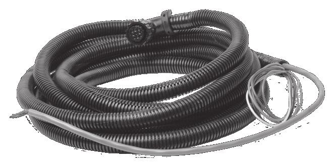
7 MESP 401A WIRE HARNESS 3 1 #1 BLUE Aux 2 Device #3 YELLOW Output 3 #5 GREEN Aux Common #6 RED 12 VDC Power #8 ORANGE Speedo Input #9 BLACK Vehicle Ground 15 ft. in length ft. in length #2 RED 12VDC Valve Supply #4 BLACK Spinner Valve #7 WHITE Auger Valve CORRUGATED LOOM (6 WIRE) CABLE PIN COLOR FUNCTION CONNECT TO 1 BLUE Aux 2 See Below 3 YELLOW Output 3 Not Used 5 GREEN Aux 1 See Below 6 RED 12vdc (power) Keyed Ign. 12V-10A 8 ORANGE Speedo input Speedo Signal 9 BLACK Ground Negative Side of battery PVC JACKETED (3 WIRE) CABLE PIN COLOR FUNCTION CONNECT TO 2 RED Valve Power Supply Common Supply to Spinner 12VDC and Auger Valves 4 BLACK Spinner Control Spinner Valve 7 WHITE Auger Control Auger Valve AUXILIARY INPUT OPTIONS Remote pushbutton switch to ground for PASS Remote pushbutton switch to ground for BLAST Remote PSI swich to ground for sensing an Auger/Conveyor stall Hi/Lo selector switch for a two speed rear axle Remote pushbutton switch to ground that shuts off MESP 401A *** When installing an auxiliary input switch, select the function type through the programming mode. (Lines 11 and 12) 7
 +12 VDC Vehicle Power Spinner Valve Coil Conveyor Valve Coil NOT USED Spinner PWM 3 YELLOW 4 BLACK Spinner Conveyor PWM 7")
8 ELECTRICAL BLOCK DIAGRAM 3 Wire Cable (See MESP 401 CBL) MESP 401A +12 VDC Vehicle Power 6 Optional Disconnect Switch Provided by Customer RED Relay PB-Start Reg. Valve Supply 2 Unloader Valve Coil RED 7 Amp Fuse (NOT Field Serviceable) +12 VDC Vehicle Power Spinner Valve Coil Conveyor Valve Coil NOT USED Spinner PWM 3 YELLOW 4 BLACK Spinner Conveyor PWM 7 Conveyor WHITE (Neg.) Ground 9 Power MOSFETS NEGATIVE GROUND BLACK AC VEHICLE MPH SENSOR MPH Signal 8 ORANGE ACd DC DCn MPH Select Sensor Type OPTION INPUT OPTION INPUT Aux. Input 1 Aux. Input 2 5 GREEN 1 BLUE Digital 1 Digital 2 8
9 MESP-401A CONTROLS AND DISPLAYS Auger Display Spinner Display Mode Display Auger Control Unload Pass Blast System OFF Mode Spinner Control System ON OPERATION INSTRUCTIONS CONTROLS LEFT HAND KNOB FUNCTIONS FEED RATE Turn to control the Auger/Conveyor. BLAST Push and release to increase the Auger/Conveyor to max speed. (BL will show on display.) (Timed interval 0-30 seconds, programming variable) UNLOAD Push and turn CCW UL will show on display. (Provides max Auger/Conveyor speed for unloading material.) ***Truck must be at 0-5 MPH for Unload to function. RIGHT HAND KNOB FUNCTIONS LANE WIDTH Turn to control the speed of the spinner. PASS Push and release to pause the operation of the Auger/Conveyor and Spinner. Push and release again to resume operation at the original settings. PA S will show on the display. 9
10 OPERATION INSTRUCTIONS RIGHT HAND KNOB FUNCTIONS CONTINUED MODE Push and turn two detents CW to select manual operation or two detents CCW to select Auto operation (Auto and Manual labels in top right corner). These will light up to indicate selected operating mode. PRODUCT SELECT Push and turn CW six detents until the display shows Pr 1 to 4; continue turning for desired product number and release button to store result. The selected product number has a decimal point preceding it when scrolling thru the four number selections. SYSTEM ON Push and release the Lane-Width knob to turn the system on. SYSTEM OFF Push both knobs simultaneously to turn the system off. OPERATION INSTRUCTIONS DISPLAYS AUTO/MANUAL LABELS Indicates mode of spreader operation. *** In Auto Mode the label and numerical displays will flash at 0 MPH. If Auto display continues to flash with the truck moving, this indicates no speedo input to MESP-401A, and the auger/conveyor will not operate. FEED RATE Manual Operation, (10) Settings are displayed (0-9) Auto Operations, (10) Settings are displayed (0-9) **Initially Auger Output displayed (Lb. /mile) ***multiply by 10 for actual output. LANE WIDTH (10) settings of spinner control (0-9) 10
11 OPERATION INSTRUCTIONS OPERATION DISPLAYS B L P A U L BLAST S PASS UNLOAD P R O R P S i PRODUCT OVERRUN-MPH TOO HIGH CONVEYOR STALL AUTO MODE OPERATION In Auto mode the truck speed (MPH) is used to automatically increase/ decrease the Auger/Conveyor speed to keep the Feed Rate (Lbs. /Mile) constant. The operator has (9) increments of Feed Rate. As the feed rate knob is turned in Auto mode, the display will show a two digit number that multiplied by 10 equals the application rate in pounds per mile. After a selection is made the display will revert to a reference number (1-9) In Auto, the Auger/Conveyor will automatically halt at 0 MPH. The auto label, feed rate, and lane width displays will continuously flash at 0 MPH Or Loss of a speedometer input if truck is moving. Auto Mode does not control the Spinner Lane Width. This is set by the operator and remains constant at all MPH speeds. MANUAL MODE OPERATION In Manual mode the Feed Rate adjustment has (10) settings. (0-9) [0=off] Each increment changes the Auger/Conveyor speed by approximately 10%, each setting will produce a constant Auger/Conveyor speed at all MPH. Therefore as MPH increases for any given Feed Rate, the actual pounds per mile will decrease; also, unlike Auto, the system will not automatically turn off the spreader output when the truck comes to a stop. The operator must use the pass function or turn the Feed Rate to 0 to stop the spreader. 11
12 MESP PROGRAMMING/SETTINGS VIEWING THE PROGRAMMING MENU SETTINGS 1. With the MESP-401A powered-off, press and hold both control knobs for 4-5 seconds. Release the control knobs when SH O is displayed. 2. It is now possible to step thru the menu lines to view the settings. To select a menu line, press and hold the Lane Width Control and turn the Feed Rate Control to the desired menu line number. Release the Lane Width Control to view the setting. 3. It is not possible to alter the menu line variables in this viewing mode. 4. To exit this mode, press and hold both controls until the display shows 888. Release the controls to return to the normal operating mode. ACCESSING AND ADJUSTING THE PROGRAMMING MENU SETTINGS 1. With the MESP-401A powered-off, press and hold both control knobs for 4-5 seconds. Release the control knobs when SH O is displayed. 2. Press and hold the Feed Rate Control and turn the Lane Width Control to enter the Pass Code in the display. Release the Feed Rate Control and Pr g will be displayed if the correct Pass Code was entered. (See the Quick Reference Programming Guide Menu # 1 for your Pass Code). 3. You may step thru the menu lines by pressing and holding the Lane Width Control and turning the Feed Rate Control to any menu line number. Release the Lane Width Control to view the setting for that menu line. 4. To adjust the variable on any menu line, press and hold the Feed Rate Control and turn the Lane Width Control to the desired setting for that menu line. When you leave that menu line, the last setting will be stored in memory. 5. To exit this mode, press and hold both control kobs until 888 is displayed. Release the control knobs to return to the normal operating mode. SELECTING THE OPERATING PARAMETERS FOR THE MESP-401A There are many options available for setting-up the operation of this spreader control system to meet your specific needs. These are contained in the Programming Menus which can be accessed and adjusted with the control knobs and displays on the front. No special hardware or computer connections are required. Programming Menus can be categorized as: (1) optional control selections, (2) setting the operator controls (options & limits) and (3) calibrations critical to accuracy. These are discussed in detail on the next page. 12
13 MESP PROGRAMMING/SETTINGS OPTIONAL CONTROL SELECTIONS AUX INPUTS 1 & 2 MENUS 11 & 12 Two (optional) input wires are provided in the wiring harness. Connection via a switch to ground on each input wire will activate a response according to the selections made on Menus 11 & 12. SELECTIONS FOR MENUS 11 & 12 SELECTIONS 0 No Action Input not used OPTION 1 Auger Jam Requires PSI switch in motor circuit 2 Remote Pass Requires a pushbutton switch 3 Remote Blast Requires a pushbutton switch 4 2-Speed Axle Input for internal speedometer adjust 5* Remote Shutdown Requires a pushbutton switch *Note: Selection (5) is only available on Menu 11 for Aux Input 1 AUGER JAM OPTION A pressure switch connected to ground and Aux Inputs 1 or 2 will stop the spreader operation if the pressure switch closes. The MESP-401A will show the operator an error code (07 E) and beep to show a potentially jammed auger. REMOTE PASS OR BLAST OPTION Connecting the Aux Input wires to a momentary push-button switch will activate these functions while the switch is depressed. Releasing it resumes normal operation. Pass will stop both spreader motors. Blast will increase the auger output to a preset level. Handles for cable controlled plow valves are available with these switches and provide a convenient control option for operators. 2-SPEED AXLE OPTION If the truck is equipped with a 2-speed axle, connect one of these Aux Inputs to the Hi-Lo axle selector. This is required for the MESP-401A to stay in sync with the speedometer function. REMOTE SHUTDOWN OPTION A momentary push-button switch connected to Aux Input 1 can provide an emergency shutdown of the MESP-401A from anywhere on the truck. Pushing the switch will immediately power-off the MESP-401A. It cannot be used to power-on the controller. 13
14 MESP PROGRAMMING/SETTINGS SETTING OPERATOR CONTROLS (OPTIONS & LIMITS) (MENUS 3-4, 9-10, 21-29, 31-41) AUTO & MANUAL MODE LOCKOUTS MENU 3 To force the operator to use the Auto operation, select option (3) on this Menu. This will lockout the Manual operation except when the truck is at 0 MPH or if the Auto mode fails. To lockout Auto, select option 1. To allow either mode to be used, select option 2. SPINNER MODES MENU 4 To turn the spinner function completely off, select option (0) on this menu. You may select option (2) to have the spinner automatically pause when the truck comes to a stop or choose option (1) to allow standard operation of the spinner whereby it will continue to run when the truck is stopped. BLAST OPERATION MENU 9 & 10 The operator can press the Feed Rate Control to activate a Blast operation. This will momentarily increase the auger output. Blast will then time-out and the auger will return to its original setting. On Menu 9, set the time-out range from 0-30 seconds for how quickly the auger will return to the original settings after the operator releases the blast. On Menu 10, set the auger speed response to blast operation. RTE = Blast output is same as Auger rate set on Menu 29. TRI = Blast output is same as Auger Max on Menu 17. Note: Blast does not affect the spinner operation. AUTO AUGER OUTPUT SELECTIONS MENU 21 TO 29 The MESP-401A allows up to (9) outputs. It is possible to set each operator selection for a specific output in terms of pounds-per-mile. For example, to have only (4) settings available to the operator, set the outputs of positions 5-9 for the same value as position 4. It is possible to set these (4) positions for virtually any desired value. The values do not need to be equal increments. For example, they could be 100, 240, 330 and 600 pounds-per-mile. Note: In Manual Mode the (9) auger rate increments are fixed and cannot be altered. SPINNER OUTPUT LIMIT MENU 31 There can be up to (9) increments of spinner control. In this menu, it is possible to select a smaller number of control increments. For example, you might only want (2); one for single lane and another for dual lanes. SPINNER SPEEDS MENU 32 TO 38 In these menu lines it is possible to adjust the spinner speed for each of the control settings you have selected above. Normally, the higher control rates of most systems produce spinner speeds that are too fast 14
15 MESP PROGRAMMING/SETTINGS to be practical. This allows finer resolution in the total operator range if you choose. POWER-UP OPERATING MODE DEFAULT MENU 39 It is possible to set this menu option to cause the system to power-up in either Auto or Manual mode. (AUT=Auto, ANU=Manual) POWER-UP FEED RATE SETTING MENU 40 It is possible to preset an auger speed immediately upon powering-up the MESP-401A. It is strongly recommended that this be set to (0) = off. POWER-UP LANE WIDTH SETTING MENU 41 It is possible to preset a spinner speed immediately upon powering-up the MESP-401A. It is strongly recommended that this be set to (0) = off. CALIBRATIONS CRITICAL TO ACCURACY (MENUS 5-8, 13-20) SPEEDOMETER INPUT & SYNCHRONIZING MENU 5, 6 & 7 Truck speedometer systems can have a variety of signal types. Menu 6 allows selecting four different input variations. Most Allison equipped trucks provide a speedometer output at the VIM (Vehicle Interface Module) or TCM (Transmission Control Module). The (dc) selection on Menu 6 is usually correct for this type. Some IHC chassis provide a connection at the ECU (Engine Control Unit). These can require using the (dcn) selection on Menu 6. For standard transmissions the speedometer connection is commonly made to the speedometer sensor on the tailshaft area of the transmission. These types of sensors produce an AC voltage, therefore the (AC) selection on Menu 6 would be selected. Finally, on Menu 6 a fourth option is available which is the (ACd) selection. This might be used if the (AC) does not work. Selecting the wrong option will not damage the MESP-401A or the speedometer system. You can quickly test the results of any selection by exiting the Programming Mode and returning to the normal operation of the MESP-401A. If the MESP-401A is on the correct selection and is receiving a usable speedometer signal the AUTO label on the front will quit flashing and go steady when the truck is moving. This will happen almost immediately after the truck begins to move. After establishing a usable speedometer signal the next step is to synchronize the MESP-401A s measure of MPH to agree with the truck speedometer. There are a couple of methods of doing this. First, if the pulse count-per-mile is known for the truck speedometer system, then it can be directly entered on Menu 6. The second method is to go to Menu 7 and adjust the displayed number to agree with the truck speedometer. This method requires somebody to drive the truck at a constant speed while another person makes the adjustment on the display at Menu 7. 15
16 MESP PROGRAMMING/SETTINGS CALIBRATIONS CRITICAL TO ACCURACY CONTINUED The accuracy of the Auto mode operation depends upon this being done with reasonable accuracy (1-2 mph error is okay) Note: If using the second option to match the MESP-401A to the truck speedometer, it is advised that you return to Menu 6 and record the Cts/ Mile that was recorded by the MESP-401A. This can be used to calibrate any other like trucks with a MESP-401A and it can used to recalibrate this truck in the future if a MESP-401A has to be exchanged for service. TWO-SPEED AXLE OPTION MENU 8 If the truck is equipped with a two-speed axle, the Hi/Lo axle switch needs to be connected to Aux Input 1 or 2 of the MESP-401A (See Installation instructions in this booklet). On Menu 8, you need to insert the axle ratio for Lo-to-Hi or Hi-to-Lo. This depends upon whether you were in Lo or Hi axle when you did the speedometer matching in the step above. The MESP-401A will use this ratio to recalculate the speedometer speed when the axle is shifted. PWM FREQUENCY MENU 13 The MESP-401A uses voltage pulses to control the current flow in the spreader valves. It varies the on and off time division of each pulse to change the current and thereby the valve s hydraulic flow. The pulses are sent at a frequency that can be set on this menu line from 30 to 300 pulses-per-second. This pulse frequency helps to vibrate the valve and keep it responsive to quick changes of position requirements. Valve manufacturers have different recommendations for the optimum frequency. Muncie s valves operate best from pulses-per-second (Hz). This technique of current control is called Pulse-Width-Modulation (PWM). AUGER & SPINNER OUTPUT CONTROL (CURRENT OR VOLTAGE) MENUS 14 & 15 Two types of electrical control of the valves are available on these menu lines. One choice is Current and the other is Voltage. Current Control is strongly recommended. This allows the MESP-401A to continuously self adjust for voltage changes and the affects of temperatures on valve coil resistance. This will produce the most consistent and accurate results. This keeps the spreader motor speeds stable and predictable. AUGER MIN & MAX TRIM MENUS 16 & 17 These settings determine the minimum and maximum current to the auger valve. The minimum current setting is very critical to the accurate operation of the spreader system. All valves have a threshold (minimum) current that must be met before the valve will begin to generate hydraulic flow. By accurately setting the minimum on Menu 16 the MESP-401A will always start its control output at this level and not at a lower value that would result in no spreading at low mph. The proper setting on Menu 16 should cause the auger to begin turning. 16
17 MESP PROGRAMMING/SETTINGS WARNING! When you press the Feed Rate Control while on this menu, the auger operation is live. Menu 17 sets the maximum auger speed available to operator and the system. It should not be set for a value higher than 90 for the best performance. WARNING! When you press the Feed Rate Control while on this menu, the auger operation is live. SPINNER MIN & MAX TRIM MENUS 18 & 19 These settings determine the minimum and maximum current to the spinner valve. The minimum current setting will establish the speed of the spinner in Position 1 on the Lane Width Control. Keep in mind line 18 will be the slowest speed available to the operator. WARNING! When you press the Feed Rate Control to change this setting the spinner will be live. On Menu 19, you may set the highest spinner speed. This will be the speed available to the operator at the highest rate selection that is set in Menu 31. WARNING! When you press the Feed Rate Control to change this setting the spinner will be live. WEIGHED-DUMP CALIBRATION MENU 20 This menu line is a very important reference for the MESP-401A to operate accurately. It tells the MESP-401A the potential of the truck spreader at full speed in terms of pounds-per-minute. The MESP-401A then relates its auger valve output current to material discharge weights. It can therefore use the MPH value of the truck and this relationship of electrical current to material discharge weight to correctly vary the auger valve. The resulting figure after performing a weighed-dump calibration should be input on this menu line. To perform this operation, please see the description of the procedure at the end of this section. ALTERNATE PRODUCTS 2, 3 & 4 CALIBRATION RATIOS MENUS 42, 43 & 44 When using more than one granular product, the MESP-401A allows for calibrating the weight/volume of any additional products as a ratio to Product 1, which is the default product that was used to determine the pounds-per-minute setting on Menu 20. To find the ratio of a second product, weigh a bucket of the first product and then refill the bucket with the second product and weigh it. Divide the weight of Product 2 by the weight of Product 1 and this will be the ratio. Install that ratio number on Menu 42. Repeat this process for a Product 3 if desired and install that ratio on Menu 43. A fourth product ratio can be installed on Menu
18 MESP PROGRAMMING/SETTINGS The operator can select these products by pressing and turning the Lane Width Control until the display shows the product number that corresponds to the material loaded in the truck. This is important to the overall accuracy of the system. If you do not want any or some of the alternate product numbers to come up for the operator s selection then leave the ratio numbers on the Menus 42, 43 & 44 set for (1) as desired. (Ex. If Menu 43 & 44 are set for (1), then only Prod 1 & 2 will appear for the operator to select). WEIGHED-DUMP CALIBRATION PROCEDURE (RESULTS GO TO MENU 20) The purpose of this procedure is to measure the discharged material weight of the spreader and measure the time of the discharge. The MESP-401A s internal micro controller can measure and control the electric current to the auger valve but it needs to have a reference for calculating electric current versus pounds-per-minute of material discharge. You will need a means to weigh material. This can be handled a couple of ways. (1) Load the truck with material and weigh the truck. Then reweigh the truck again after doing the material discharge. (2) Capture the discharged material and weigh it. You should discharge several hundred pounds of material to get an accurate measure of the spreader system. If you elect to weigh the discharged material, you may have to weigh the pile in manageable accurate segments by shoveling it into a container size that does not exceed the maximum weight limit of the scales, and make multiple weighs. THE PROCESS: 1. Fill the truck with material. (Weigh the truck loaded if this is the method you are using to determine discharge weight.) 2. Position the truck for a stationary operation of the spreader. 3. Set the engine speed for 1500 RPM. This is so the pump is producing adequate flow to generate maximum speed for the spreader operation. 4. If your truck is equipped with a tailgate spreader, raise the dump body to fill the auger. 5. If your truck is equipped with a conveyor spreader, set the gate height for normal operations. 6. Turn on the MESP-401A and select Manual Operation. 7. Observe a second hand on a clock or watch and then turn the Feed Rate Control to (9) to begin the material discharge. 8. Time the material discharge for 1-2 minutes if you are collecting it to weigh. If you are going to re-weigh the truck you should let the discharge run for 5-10 minutes to get enough weight off for the truck scales to detect. 9. Shut off the MESP-401A after the discharge of material is complete. 18
19 MESP PROGRAMMING/SETTINGS Once the weight of the discharged material is determined, divide the weight by the number of minutes of operation. This will tell you the Pounds-Per Minute. Input the Pounds-Per-Minute number on Menu 20. TYPICAL SPREADER DISCHARGE RATES Tailgate auger style spreaders will typically discharge Pounds-Per-Minute. Slide-in V-box spreaders will typically discharge Pounds-Per- Minute at 2-4 inches of gate height. Frame mounted & Muni-body spreaders will typically discharge Pounds-Per-Minute at 2-4 inches of gate height. MESP-401A TROUBLESHOOTING SYMPTOM MESP-401A will not turn on. No Auto Mode Function. POSSIBLE CAUSE Blown internal fuse-requires factory service. If auto mode blinks when truck is moving, then no speedo input. Program menu 3 is set for (1) = Auto Lockout. Program menu 7 display does not match truck Speedometer. Auto Mode does not perform at low MPH. Manual Mode does not work with truck moving Auger and Spinner Valves inoperative Auger or Spinner Valve does not turn off at (0) on Rate Control No Auger or Spinner operation at low rates. Program menu 7 display does not match truck. Speedo program menu 17 is not set correctly. Program menu 20 and weighted dump calibration are in error. Program menu 3 is set for (3) = Auto only. Common voltage supply is open-check wire continuity and connections. Open control side wires or connections. See Cable Drawings Control side of valve wire shorted to ground, check wire continuity and cable drawings. Program menu 16 is set too low for Auger. Program menu 18 is set too low for Spinner. 19
20 MESP TROUBLESHOOTING MESP-401A ERROR CODES ERROR 01E 02E 03E 04E 05E 06E 07E 08E 09E DESCRIPTION Shorted Auger valve coil or voltage supply Shorted to Auger control wire Open Auger valve coil or open Auger control wire Shorted Spinner valve coil or voltage supply Shorted Spinner control wire Open Spinner valve coil or open Spinner control wire Internal Fuse Blown Factory Service Required Low Voltage to MESP 401A (Below 10.5V) measure voltage on Red wire to MESP 401A when valves are ON Hi PSI Switch in Auger Line closed to ground, check Auger pressure, switch, and wire connection. Output 3 Not Used- (Yellow) shorted to ground Output 3 Not Used- (Yellow) open Muncie Power Products, Inc. Member of the Interpump Hydraulics Group General Offices and Distribution Center P.O. Box 548 Muncie, IN (765) FAX (765) info@munciepower.com Web site Drive Products, Exclusive Agents for Canada, ISO Certified by an Accredited Registrar IN09-07 Printed in the U.S.A. Muncie Power Products, Inc. 2009
AS302SG OPERATIONS MANUAL PART NUMBER: SG REV: D
 AS302SG OPERATIONS MANUAL PART NUMBER: SG07230003 REV: D Factory Operations Manual Electronic Ground Speed Spreader Control with pre-wet liquid control For assistance with installation, operation, programming,
CS 420RC. Solid De-icer Controller Configuration and Set-up Manual
 CS 420RC Solid De-icer Controller Configuration and Set-up Manual 2/15 Table of Contents 1 Systems Modes of Operation 3 2 System Features 4 3 System Description 5 4 System Specifications 6 4.1 CS-420RC
CS 430RC. Solid De-icer Controller Configuration and Set-up Manual
 CS 430RC Solid De-icer Controller Configuration and Set-up Manual 2/17 Table of Contents 1 Systems Modes of Operation 3 2 System Features 4 3 System Description 5 4 System Specifications 6 4.1 CS-430RC
CS102 Spreader Control Manual. General Description
 CS102 Spreader Control Manual CS102M1A General Description The CS102 implements a digital rate control for granular and liquid systems typically used to regulate snow and ice highway spreading equipment.
SAVE S ALT SAVE MONEY SAVE T IME
 SAVE S ALT SAVE MONEY SAVE T IME WITH GROUND-SPEED CONTROL When winter strikes, having snow and ice removal equipment with groundspeed control that functions efficiently and effectively is critical to
OPERATIONS, SERVICE & PARTS MANUAL SNOW & ICE PRODUCTS PERFORMANCE ECONOMY CONVENIENCE SAFETY
 OPERATIONS, SERVICE & PARTS MANUAL SNOW & ICE PRODUCTS PERFORMANCE ECONOMY CONVENIENCE SAFETY This manual contains the most up to date information available at the time of printing. In the event that revised
MB A 12V/24V DC PROGRAMMABLE DUAL BATTERY ISOLATOR
 MB-3688 120A 12V/24V DC PROGRAMMABLE DUAL BATTERY ISOLATOR User Manual Warning and Precautions MB-3688 is built with corrosion resistant material and the main electronic assembly is well sealed inside
Installation and Maintenance Instructions. World Leader in Modular Torque Limiters. PTM-4 Load Monitor
 World Leader in Modular Torque Limiters Installation and Maintenance Instructions PTM-4 Load Monitor 1304 Twin Oaks Street Wichita Falls, Texas 76302 (940) 723-7800 Fax: (940) 723-7888 E-mail: sales@brunelcorp.com
VC-4820 Programmable DC-DC Converter with Battery Charger function USER'S MANUAL
 1. INTRODUCTION VC-4820 Programmable DC-DC Converter with Battery Charger function USER'S MANUAL This MCU controlled Step Down DC-DC Converter has a digitally adjustable output in 0.2V increments. This
Section 55 Chapter 6
 Section 55 Chapter 6 REMOTE HYDRAULICS CONTROLLER Calibration and Fault Codes 6-12880NH TABLE OF CONTENTS REMOTE HYDRAULICS CONTROLLER CALIBRATION... 55-5 Requirements For Calibration... 55-5 Aux Set Main
MODEL 422 Submersible Pump Controller
 MODEL 422 Submersible Pump Controller Monitors True Motor Power (volts x current x power factor) Detects Motor Overload or Underload Operates on 120 or 240VAC, Single-phase or 3-phase Built-in Trip and
Gresen GRS32 Calibration (also see the MnDOT Salt and Sander Calibration Guide for general calibration reference)
") Gresen GRS32 Calibration (also see the MnDOT Salt and Sander Calibration Guide for general calibration reference) 12/21/2009 Page 1 Gresen Calibration Guide for Mn/DOT by EVS Gresen GRS32 Calibration Table
Gresen GRS32 Calibration (also see the MnDOT Salt and Sander Calibration Guide for general calibration reference) 12/21/2009 Page 1 Gresen Calibration Guide for Mn/DOT by EVS Gresen GRS32 Calibration Table
6 Gauge Box Set IS0333
 Caution 6 Gauge Box Set IS0 Rev. B ecr 882 9/202 Disconnect the battery during installation. Tighten nuts on the back clamp only slightly more than you can tighten with your fingers. Six inch-pounds of
ADVANTAGE PLUS Installation Instructions
 ADVANTAGE PLUS Installation Instructions TABLE OF CONTENTS Electrical Controls... 3 Electrical Sensors... 4 Hydraulic Component Breakdown... 5 Tank Enclosure / Mounting Recommendation... 6 Hydraulic Installation
VOLUMETRIC BLENDING SYSTEM OPERATION MANUAL
 VOLUMETRIC BLENDING SYSTEM OPERATION MANUAL 12285 E. MAIN ST. MARSHALL, IL 62441 PHONE: 217-826-6352 FAX: 217-826-8551 WEB SITE: www.yargus.com 1 OPENING SCREEN The OPENING SCREEN is the screen that the
TITLE PAGE... 1 HOW IT WORKS... 2 CALIBRATION VALUES... 4 SYSTEM PARAMETERS... 4 HYDRAULIC PARAMETERS... 6 TRUCK PARAMETERS... 8
 TITLE PAGE... 1 HOW IT WORKS... 2 CALIBRATION VALUES... 4 SYSTEM PARAMETERS... 4 HYDRAULIC PARAMETERS... 6 TRUCK PARAMETERS... 8 SPEEDOMETER CALIBRATION.... 10 OPERATOR SET UP... 11 TROUBLESHOOTING AND
DIESEL Engine Fire Pump Controllers Features
 1-1 Printer / Recorder The industrial grade thermal printer is housed in a rugged steel enclosure within the controller. The on/off switch, feed and reset buttons are front accessible. A bi-color status
Automotive Application ET01 Software Revision A 12/06
 Automotive Application ET01 Software Revision A 12/06 INTRODUCTION... 2 FUNCTIONAL DESCRIPTION... 3 INSTALLATION... 4 COMPONENT PLACEMENT... 4 PLUMBING AND WIRING... 5 MSBC OPERATION (ET-01)... 14 TIMED
User Manual. T6 Tachometer. Online: Telephone: P.O. Box St. Petersburg, Florida 33736
 User Manual T6 Tachometer Online: www.phareselectronics.com Telephone: 727-623-0894 P.O. Box 67251 St. Petersburg, Florida 33736 Table of Contents Overview... 1 Description... 1 Wiring... 1 T6 Tachometer
DP10001 UNIVERSAL 5 GAUGE DIGITAL PANEL
 Nordskog Performance Products DP10001 UNIVERSAL 5 GAUGE DIGITAL PANEL **Before beginning the installation, read through these instructions thoroughly. Also, disconnect the positive battery cable to avoid
FREEDOM 2 Quick Start Guide
 FREEDOM 2 Quick Start Guide DOCUMENT P/N SG07230026 REV: H DATE: 09/29/15 THIS DRAWING IS COPYRIGHTED AND IS THE PROPERTY OF CERTIFIED POWER INC. Des Moines, IA Burnsville, MN Mundelein, IL (800) 333 7411
VC-30 / VC-40 Programmable DC-DC Converter with Battery Charger function USER'S MANUAL
 1. INTRODUCTION VC-30 / VC-40 Programmable DC-DC Converter with Battery Charger function USER'S MANUAL This MCU controlled Step Down 24V to 12V DC-DC Converter has a programmable 12.0 to 15.0V output in
CONTROL BOX. Wiring the control box into the vehicle. +12V
 CONTROL BOX Once the display panel is in place, mount the control box within the connecting cable's distance (approximately 3 feet) and secure to the underside of the dashboard. This case does not have
PCS GEAR SELECT MODULE USER GUIDE v4.0
 PCS GEAR SELECT MODULE USER GUIDE v4.0 Ph: 1.804.227.3023 www.powertraincontrolsolutions.com Powertrain Control Solutions 1 Introduction 1.1 Included Components 1 - GSM Cable Motor Enclosur 1 - GSM Driver
ECU-02 Ver2.1 Automatic Engine Control Unit Operators Manual
 ECU-02 Ver2.1 Automatic Engine Control Unit Operators Manual Headquarters : No.3, Lane 201, Chien Fu St., Chyan Jenn Dist., Kaohsiung, TAIWAN Tel : + 886-7-8121771 Fax : + 886-7-8121775 URL : http://www.kutai.com.tw
INSTALLATION GUIDE Table of Contents
 CT-3100 Automatic transmission remote engine starter systems. What s included..2 INSTALLATION GUIDE Table of Contents Door lock toggle mode..... 4 Notice...2 Installation points to remember. 2 Features..2
CS 550/150RC Towplow. Spreader Joystick Controller Operator Manual
 CS 550/150RC Towplow Spreader Joystick Controller Operator Manual 2/16 Table of Contents 1 Panel Controls 3 2 Program Screen Layout 4 3 Screen Controls 5 3.1 Pause 5 3.2 Blast 5 3.3 Reverse 5 3.4 Change
5 Gauge Box Set IS0342
 Caution 5 Gauge Box Set IS0342 Rev. B ecr 8832 9/202 Disconnect the battery during installation. Tighten nuts on the back clamp only slightly more than you can tighten with your fingers. Six inch-pounds
INSTALLATION GUIDE Six Gauge Universal Digital Dash Panel Part Number: DP10002
 Made in America Lifetime Guarantee Thank you for purchasing this digital dash panel from Intellitronix. We value our customers! INSTALLATION GUIDE Six Gauge Universal Digital Dash Panel Part Number: DP10002
GENERAL INFORMATION. H-1649, H-1650, H-1651 H-1653, H-1654 Easy-Count. uline.com. that may hurt accuracy:
 π H-1649, H-1650, H-1651 H-1653, H-1654 Easy-Count counting scale 1-800-295-5510 uline.com 1-800-295-5510 GENERAL INFORMATION Avoid placing the scale in locations that may hurt accuracy: 1. Temperature
5001TCP SPEED CONTROLLER
 INSTALLATION AND SETTING UP MANUAL 5001TCP SPEED CONTROLLER WARNING Disconnect all incoming power before working on this equipment. Follow power lockout procedures. Use extreme caution around electrical
Installation Instructions Crossfire Spreader 64740, 66263, and 66264
 Form 1-1091R1 July 2016 Installation Instructions Crossfire Spreader 64740, 66263, 64742 and 66264 Determining Vehicle Payload It is necessary to calculate the available material payload to prevent overloading
6500DC Dual Motor Wireless Controller Kits
 6500DC Dual Motor Wireless Controller Kits READ ALL DIRECTIONS FIRST BEFORE PROCEEDING NOTE: SEE THE QUICK PROGRAM INSTRUCTIONS BEFORE OPERATING THE FIRST TIME. DO NOT REMOVE THE TRANSMITTER BATTERY Please
SPREADER SYSTEM. Proportional three function. 1. Features and Specifications. User Manual 12 INPUTS 12 OUTPUTS CONNECTIVITY MAIN FEATURES
 User Manual SPREADER SYSTEM Proportional three function 12 INPUTS 3 interrupt digital inputs. 3 digital inputs for engine control (alternator, accelerator, oil alarm). 1 digital input for tachometer (squared,
Do isolate the power supply from other high power systems such as Stereos and Alarms
 Thank you for purchasing a Smart Ride Air Management System, AIRBAGIT.COM s premier flagship product. This system will meet all of your custom and utility needs and will provide you years of trouble free
CENTROIDTM. AC Brushless Drive. Product Spec Sheet
 4 Axis, up to 2 KW motors Brake Output for each axis Overtemp and Overcurrent Protection All-software Configuration Self-cooled Fiber Optic Control CENTROIDTM AC Brushless Drive Product Spec Sheet AC Brushless
650DC DUAL MOTOR CONTROLLER.
 650DC1 RECEIVER 650DC DUAL MOTOR CONTROLLER. NOTE THE TRANSMITTER HAS BEEN PROGRAMMED, it may be necessary to reprogram by following the specific directions in this manual. DO NOT REMOVE THE TRANSMITTER
SPA MICROPROCESSOR COMBINED TACHO&SPEEDO/GAUGE INSTALLATION AND OPERATING MANUAL PAGE 2...INSTRUMENT FEATURES PAGE 3...OPERATING INSTRUCTIONS
 SPA MICROPROCESSOR COMBINED TACHO&SPEEDO/GAUGE INSTALLATION AND OPERATING MANUAL PAGE 2...INSTRUMENT FEATURES PAGE 3...OPERATING INSTRUCTIONS PAGE 3...MENU SYSTEM PAGE 9...INSTALLATION DIAGRAMS PAGE 13...INSTALLATION
485 3P CONTROL BOX Technical Manual
 1st Edition Revision 1.01 3-08-12 Truck ID # User Manifold # Pump # Control Box # Valve Driver # S.O. # P.O. # 485 3P CONTROL BOX Technical Manual PENGWYN 2550 W. FIFTH AVENUE COLUMBUS, OH 43204 1 PENGWYN
ITA / ITB - AS / AP / AP SERIES Electronic Table Top Weighing Balance
 TM ITA / ITB - AS / AP / AP SERIES Electronic Table Top Weighing Balance Scale Users Guide ISHTAA SCALES INC., INDIA www.ishtaascales.com 14 Content 1. Technical Data... 1 2. Installation... 2 3. Controls
MapDCCD Version 2 Installation and setup guide
 MapDCCD Version 2 Installation and setup guide Overview of operation modes There are three main operation modes available. Any of the modes can be selected at any time. The three main modes are: manual,
EV Display User Guide
 EV Display User Guide CleanPowerAuto LLC Brief Description: EV Display is designed to track battery state of charge and other related data in battery powered Electric Vehicle. EV Display is primarily designed
Part Number DP6003 Chevy Truck Digital Dash YEARS 67-72
 Part Number DP6003 Chevy Truck Digital Dash YEARS 67-72 KIT COMPONENTS: One (1) Digital Circuit Board One (1) Smoked Acrylic See-Through Lens *Peel off protective covering from both sides of lens attached
FORCE UNLTD. SPREADERS*GPS EQUIPMENT*CONVEYORS
 FORCE UNLTD. SPREADERS*GPS EQUIPMENT*CONVEYORS SAFETY INFORMATION PAGE NO. Signal Word Definitions 0.1 OPERATING INSTRUCTIONS PAGE NO. 24" & 30" Spinner Disc Location 1.1 Fin Location 1.2 Conveyor Speed
ECONOMISER SERIES E2T USER MANUAL
 TURBO S.R.L. Electronic Control Systems for Dust Collectors e-mail: info@turbocontrols.it web: www.turbocontrols.it TEL. ++39 (0)362 574024 FAX ++39 (0)362 574092 ECONOMISER SERIES E2T USER MANUAL 24/06/2014
PRESSURE GOVERNOR, ENGINE MONITORING, AND MASTER PRESSURE DISPLAY MODEL: TCA100
 Document Number: XE-TCA1PM-R0A TCA100 Rev0511 PRESSURE GOVERNOR, ENGINE MONITORING, AND MASTER PRESSURE DISPLAY MODEL: TCA100 FIRE RESEARCH CORPORATION www.fireresearch.com 26 Southern Blvd., Nesconset,
INSTALLATION GUIDE Chevrolet Digital Dash Panel Part Number: DP6003 Year Series:
 INSTALLATION GUIDE Chevrolet Digital Dash Panel Part Number: DP6003 Year Series: 1967-1972 * Disconnect the battery before attempting any electrical work on your vehicle. * KIT COMPONENTS One (1) Digital
FM200 FLOW/NO-FLOW MONITOR INSTALLATION AND TECHNICAL MANUAL 120 VAC MODEL 6/1/2017
 FM200 FLOW/NO-FLOW MONITOR INSTALLATION AND TECHNICAL MANUAL 120 VAC MODEL 6/1/2017 Maxi-Tronic, Inc. 417 Wards Corner Road Loveland, OH 45140 513.398.2500 800.659.8250 FAX: 513.398.2536 info@maxitronic.com
Informational Distribution List:
 Technical Bulletin 2017 Southern Technologies Corporation (STC). All rights reserved. Bulletin Number: TB-2017198-BW01 Date Published: 07/17/2017 Summary: Instructions for mounting, aligning and setting
Overview. References TEST SPECIFICATION FORT WORTH, TEXAS TROTTER CONTROLS REPORT X TS-0005 A MODEL ORDER TITLE BY CHK D. Tests
 Rev A, 5/26/2009 1 26 Overview This document describes the use of the Maintenance System. This test is a built in diagnostic feature of the GEN II System and provides maintenance personnel with a diagnostic
Reference Manual /12
 DrillMaster Planter Drive Controller Reference Manual 612366-03/12 Table of Contents Description of Operation, Safety and Care.............. 1 Installation.................................... 2-3 Tractor
BLDC SPEED CONTROL INSTRUCTION MANUAL Low voltage Brushless DC control
 BLDC SPEED CONTROL INSTRUCTION MANUAL Low voltage Brushless DC control Phone 712.722.4135 groschopp.com 420 15th St NE, Sioux Center, IA 51250 Toll-Free 800.829.4135 Email sales@groschopp.com FAX 712.722.1445
FORCE UNLTD. SPREADERS*GPS EQUIPMENT*CONVEYORS
 FORCE UNLTD. SPREADERS*GPS EQUIPMENT*CONVEYORS SAFETY INFORMATION PAGE NO. Signal Word Definitions 0.1 OPERATING INSTRUCTIONS PAGE NO. 24" & 30" Spinner Disc Location 1.1 Fin Location 1.2 Conveyor Speed
The function of this Dynamic Active Probe has divided into three preferences on the screen main Menus:
 1.0 Introduction: This probe is designed to provide an additional help to automotive technicians in trouble shooting of electrical circuits problems in the car. Apart from using the normal multi tester,
Overview of operation modes
 Overview of operation modes There are three main operation modes available. Any of the modes can be selected at any time. The three main modes are: manual, automatic and mappable modes 1 to 4. The MapDCCD
Lingenfelter NCC-002 Nitrous Control Center Quick Setup Guide
 Introduction: Lingenfelter NCC-002 Nitrous Control Center Quick Setup Guide The NCC-002 is capable of controlling two stages of progressive nitrous and fuel. If the NCC-002 is configured only for nitrous,
5001TCP SPEED CONTROLLER
 VARIABLE SPEED DRIVE CONTROLLER INSTALLATION AND SETTING UP MANUAL 5001TCP SPEED CONTROLLER With PC101 Torque Limit Control WARNING Disconnect all incoming power before working on this equipment. Follow
Intelli-Feed Controller User s Manual Intelli-Feed Digital Tachometer and Hourmeter
 Intelli-Feed Controller User s Manual Intelli-Feed Digital Tachometer and Hourmeter Part #: 9047 Table of Contents: Table of Contents 2 Intelli-Feed TM User Interface 3 Equipment Diagnostic Indicators
RATE CONTROLLED TORQUE WRENCH TESTER
 RATE CONTROLLED TORQUE WRENCH TESTER OPERATOR S HANDBOOK (PART NO. 34078) ISSUE 8 NORBAR TORQUE TOOLS LTD, Beaumont Road, Banbury, Oxfordshire, OX16 1XJ, UNITED KINGDOM Tel : + 44 (0) 1295 270333, Fax
INSTALLATION GUIDE Chevrolet Impala/Caprice Digital Dash Panel Part Number: DP1208 Year Series: 1968
 Made in America Lifetime Guarantee Thank you for purchasing this instrument from Intellitronix. We value our customers! INSTALLATION GUIDE Chevrolet Impala/Caprice Digital Dash Panel Part Number: DP1208
PORT-A-WEIGH CRANE SCALES
 MSI4260 PORT-A-WEIGH CRANE SCALES User Guide Quality Industrial Weighing and Force Measurement Equipment Measurement Systems International Page 2 MSI-4260 Port-A-Weigh User Guide TABLE OF CONTENTS Introduction...
ARCHITECTURAL CONTROL SYSTEMS, INCORPORATED ST. LOUIS, MISSOURI
 II 1400-6 ARCHITECTURAL CONTROL SYSTEMS, INCORPORATED ST. LOUIS, MISSOURI ACSI 1426-04-AO ELECTRIC LATCH RETRACTION CONTROLLER INSTALLATION INSTRUCTIONS I.D. 1092, REV. C INSTALLATION For C-UL Listed applications,
MASTER SALT SAND SPREADER WIRELESS CONTROL MANUAL
 MASTER SALT SAND SPREADER WIRELESS CONTROL MANUAL This manual covers 1. Gas spreader wireless controllers (Standard) 2. Gas spreader wireless controllers (Plus) 3. 600DC single motor spreader wireless
MD10. Engine Controller. Installation and User Manual for the MD10 Engine Controller. Full Version
 MD10 Engine Controller Installation and User Manual for the MD10 Engine Controller. Full Version File: MartinMD10rev1.4.doc May 16, 2002 2 READ MANUAL BEFORE INSTALLING UNIT Receipt of shipment and warranty
SECTION 2 - PROCEDURES. Features. 2.6 MOTOR CONTROLLER. Modes of Operation JLG Lift 2-5
 2.6 MOTOR CONTROLLER. Modes of Operation. 1. Traction Motor Drive. a. Drive in either forward or reverse will start only if the following conditions are satisfied: 1. Function switches off. 2. No procedure
Specifications. General
 For sales & service call Transport Support Tel: +44 (0)1204 368 111 TS Rigid Inclinometer Installation and Operating Instructions ISO9001 CERTIFIED COMPANY United Registrar of Systems Cert. No.1820 Transport
PSC1-003 Programmable Signal Calibrator
 PSC1-003 Programmable Signal Calibrator Description: The PSC1-003 Programmable Signal Calibrator provides precise calibration of fuel by adjusting fuel control signals. It can be used with naturally aspirated
SST-3 Start-Stop-Throttle
 SST-3 Start-Stop-Throttle Installation & Operation Guide Revision 1.1 Internet: www.wiredrite.com E-mail: info@wiredrite.com Page 1 CONTENTS Introduction 2 Hardware Mounting 2 Connections 2 Operation &
AIR CLEANERS Model MC 3000 OWNER S MANUAL CAUTION Read complete instructions before operating. Please file for future reference.
 AIR CLEANERS Model MC 3000 OWNER S MANUAL CAUTION Read complete instructions before operating. Please file for future reference. MODEL MC 3000 SPECIFICATION Input Volts: 208-230/430 VAC, 60Hz, 3 Phase
3200NT Timer Service Manual
 Service Manual Valve Serial Number Valve Position 1-LEAd 2-LAg 3-LAg 4-LAg IMPORTANT: Fill in pertinent information on page 3 for future reference. Table of Contents Job Specifications Sheet.....................................................................
OPERATING MANUAL Digital Diesel Control Remote control panel for WhisperPower generator sets
 Art. nr. 40200261 OPERATING MANUAL Digital Diesel Control Remote control panel for WhisperPower generator sets WHISPERPOWER BV Kelvinlaan 82 9207 JB Drachten Netherlands Tel.: +31-512-571550 Fax.: +31-512-571599
715B CONTROL SERIES. Instruction Manual Line Voltage DC Brushless Motor Control CONTROLS. Phone (317) Fax (317)
 Fax (317)") 715B CONTROL SERIES CONTROLS Instruction Manual Line Voltage DC Brushless Motor Control LT715B (IM-715B-0100) P.O. Box 10 5000 W. 106th Street Zionsville, Indiana 46077 Phone (317) 873-5211 Fax (317) 873-1105
715B CONTROL SERIES CONTROLS Instruction Manual Line Voltage DC Brushless Motor Control LT715B (IM-715B-0100) P.O. Box 10 5000 W. 106th Street Zionsville, Indiana 46077 Phone (317) 873-5211 Fax (317) 873-1105
DOC # DOCSST-D 08/16/99
 DOC # DOCSST-D 08/16/99 Wired Rite Systems 5793 Suite A, Skylane Blvd., Windsor Ca. 95492 Phone: (800) 538-7483 Or (707) 838-1122 Fax: (800) 525-7483 WEB: http://www.wiredrite.com E-MAIL: Info@wiredrite.com
ADJUSTABLE FREQUENCY CRANE CONTROLS
 IMPULSE G+ MINI ADJUSTABLE FREQUENCY CRANE CONTROLS The IMPULSEG+ Mini from Magnetek continues our history of providing the most reliable and cost-effective adjustable frequency crane controls available.
INSTALLATION INSTRUCTIONS FOR SYMCOM'S MODEL 777-HVR-SP ELECTRONIC OVERLOAD RELAY
 CONNECTIONS INSTALLATION INSTRUCTIONS FOR SYMCOM'S MODEL 777-HVR-SP ELECTRONIC OVERLOAD RELAY BE SURE POWER IS DISCONNECTED PRIOR TO INSTALLATION!! FOLLOW NATIONAL, STATE AND LOCAL CODES! READ THESE INSTRUCTIONS
ALTERNATOR - CHRYSLER 40/90-AMP & 50/120 AMP
 ALTERNATOR - CHRYSLER 40/90-AMP & 50/120 AMP 1988 Chrysler LeBaron Convert/Coupe 1988 ELECTRICAL Chrysler Motors 40/90 & 50/120 Amp Alternators FWD Models DESCRIPTION The charging system consists of an
Subject: Power Take Off (PTO) Models Affected: ADVISORY:
 Models Affected: ADVISORY:") Subject: Power Take Off (PTO) Subsystem Operating Description and Application Guide Models Affected: All New C/K 3500HD CC Chevrolet Silverado / GMC Sierra. Models C/K 36003, 36403 & 36043 Model Years:
Subject: Power Take Off (PTO) Subsystem Operating Description and Application Guide Models Affected: All New C/K 3500HD CC Chevrolet Silverado / GMC Sierra. Models C/K 36003, 36403 & 36043 Model Years:
K10 Intrinsically Safe Electro-Pneumatic Positioner Operating Manual
 K0 Intrinsically Safe Electro-Pneumatic Positioner Operating Manual Pneumatic Connection Outlet Port Gauge Single Acting Actuator (Spring Return): For single acting actuators Outlet Port 2 is to be plugged.
THUNDERBIRD. Agricultural Weighing Systems SS1000 Instructions
 THUNDERBIRD Agricultural Weighing Systems SS1000 Instructions Installation Locate a weighing site that is well drained. For best weighing results, ensure the weigh bars and weighing platform are on a level
MODEL RMS INSTALLATION INSTRUCTIONS. CONTENTS Page A. Introduction 1. Usage 2 2. How it operates 2
 CONVEYOR COMPONENTS COMPANY Division of Material Control, Inc. 130 Seltzer Road, PO Box 167 Croswell, MI 48422 USA PHONE: (810) 679-4211 TOLL FREE (800) 233-3233 FAX: (810) 679-4510 Email: info@conveyorcomponents.com
INSTALLATION GUIDE Ford Mustang Digital Dash Panel Part Number: DP7009 Year Series:
 Made in America Lifetime Guarantee Thank you for purchasing this gauge panel from Intellitronix. We value our customers! INSTALLATION GUIDE Ford Mustang Digital Dash Panel Part Number: DP7009 Year Series:
WTEC III SHIFT SELECTOR
 WTEC III SHIFT SELECTOR P.O. Box 894, Speed Code PF3 Indianapolis, Indiana 46206-0894 www.allisontransmission.com Oil level information, diagnostic codes and prognostic features for SA7297EN (2012/12)
Freedom XDS Calibration Manual
 Calibration Manual P/N SG07230041 REVISION A REV DATE 08/09/14 THIS DRAWING IS COPYRIGHTED AND IS THE PROPERTY OF CERTIFIED POWER INC. Des Moines, IA (800) 333 7411 Bridgeton, MO (800) 999 7411 Burnsville,
Model DS7060 Handrail Scale. User Manual
 Model DS7060 Handrail Scale User Manual Doran Scales, Inc. 1315 Paramount Pkwy Batavia, IL 60510 USA 1-800-264-4107 www.doranmedical.com MAN0302 Revision 0.0 TNW 2/20/2013 Section 1. Unpacking and Installation...
RADIO FREQUENCY SYSTEMS
 C14520.016-E.MU0 DOC.:10000008168-02 LAB4 DEHYDRATOR USER MANUAL 1 DRYING CHAMBER 2 HEATER 3 PUMP 4 AIR BACKWASHING HOLE 5 HUMIDITY PROBE 6 DIGITAL PRESSURE GAUGE 7 RELIEF VALVE 8 SHUT OFF VALVE 9 DRY
MODEL MCL /8 SPEEDOMETER/TACHOMETER for 2004 up
 MODEL MCL-3204 3-3/8 SPEEDOMETER/TACHOMETER for 2004 up IMPORTANT NOTE! This gauge has an odometer preset option that is only available one time in the first 100 miles (160km) of operation. See Odometer
UTV-1200 Multi Gauge for 2008 Yamaha Rhino
 IMPORTANT NOTE! This gauge has an hour meter and odometer preset option available only for the first 1.0 engine hour and 10 miles (16km). See ODO/HR PRESET for instructions. UTV-1200 Multi Gauge for 2008
6000DC Single 12V Motor Wireless Controller Kits With Extra Options
 6000DC Single 12V Motor Wireless Controller Kits With Extra Options READ ALL DIRECTIONS FIRST BEFORE PROCEEDING NOTE: SEE THE QUICK PROGRAM INSTRUCTIONS BEFORE OPERATING THE FIRST TIME. DO NOT REMOVE THE
Induction Power Supplies
 Induction Power Supplies 7.5kW; 135 400kHz 480V version (Integral Heat Station) User s Guide Model 7.5-135/400-3-480 SMD Control Brds Rev. D 5/08 Table of Contents 1. Specifications and features...3 2.
Quick Setup Guide for IntelliAg Model YP Air Pro
 STEP 1: Pre-Programming Preparation: The Quick Guide assumes the Virtual Terminal, Master Switch, Working Set Master, Working Set Member, and all sensors have been connected and properly installed. Reference
RD712 & RD712XL Remote Displays. Model 615 / 615XL Indicator User s Manual
 RD712 & RD712XL Remote Displays Model 615 / 615XL Indicator User s Manual EUROPEAN COUNTRIES WARNING This is a Class A product. In a domestic environment this product may cause radio interference in which
Speed Sentinel II Programmable Road Speed Limiter
 An ISO 9001:2008 Registered Company Speed Sentinel II Programmable Road Speed Limiter SS501-A, SS501-AX Ford E Series 2005-2008 Ford F250-F550 Series 2008-2010 Ford Crown Victoria 2005-2008 Contact InterMotive
UTV-1000 Multi Gauge for Yamaha Rhino
 IMPORTANT NOTE! This gauge has an hour meter and odometer preset option available only for the first 1.0 engine hour and 10 miles (16km). See ODO/HR PRESET for instructions. UTV-1000 Multi Gauge for 2004-2006
INTRODUCTION. Specifications. Operating voltage range:
 INTRODUCTION INTRODUCTION Thank you for purchasing the EcoPower Electron 65 AC Charger. This product is a fast charger with a high performance microprocessor and specialized operating software. Please
GM6B SERIES PTO INSTALLATION FOR GENERAL MOTORS 3600 CAB CHASSIS WITH ALLISON 1000 SERIES AUTOMATIC TRANSMISSION
 KEEP IN VEHICLE READ OPERATING INSTRUCTIONS INSIDE BEFORE OPERATING PTO GM6B SERIES PTO INSTALLATION FOR GENERAL MOTORS 3600 CAB CHASSIS WITH ALLISON 1000 SERIES AUTOMATIC TRANSMISSION Use this manual
Power Distribution System User s Manual. Model: PDS-100
 Power Distribution System User s Manual Model: PDS-0 Section Page Product Overview... 1 I) General Information... 2 II) Important Safety Information... 2 III) Installation... 3 A) Materials Provided...
MAGPOWR Spyder-Plus-S1 Tension Control
 MAGPOWR TENSION CONTROL MAGPOWR Spyder-Plus-S1 Tension Control Instruction Manual Figure 1 EN MI 850A351 1 A COPYRIGHT All of the information herein is the exclusive proprietary property of Maxcess International,
Rally computer 3 Rally computer 3.GPS *
 Rally computer 3 Rally computer 3.GPS * User manual. Installation and configuration instructions. (with links to video instructions online at : www.rallycomputer.com ) * Content marked applies only to
PRO-SET CC800A Series Programmable Charging Scale CERTIFIED
 PRO-SET CC800A Series Programmable Charging Scale CERTIFIED Calibrated to standards traceable to the National Institute of Standard and Technology (NIST). CC800A SPECIFICATIONS Working Load Capacity: 0-220lbs
Designed for ease of integration with automation systems
 BAS, 200 ~ 600V, 1/2-30HP BUILDING AUTOMATION STARTER SMARTER AND MORE VERSATILE THAN EVER Smartstart Equipped with advanced I/O including Fireman s Override and damper control, the BAS was designed from