UNIVERSITY OF NAIROBI DESIGN OF AN INVERTER DRIVE FOR A DC MOTOR. Project Number: PRJ 077. By OWITI EMMANUEL ONDIEGE F17/8281/2004
|
|
|
- Candice McDaniel
- 5 years ago
- Views:
Transcription

1 UNIVERSITY OF NAIROBI DESIGN OF AN INVERTER DRIVE FOR A DC MOTOR Project Number: PRJ 077 By OWITI EMMANUEL ONDIEGE F17/8281/2004 Supervisor: MR. S.L OGABA Examiner: MR. V.M DHARMADHIKARY Project report submitted in partial fulfillment of the requirement for the award of the degree of Bachelor of Science in Electrical and Electronic Engineering of the University of Nairobi 20 th MAY 2009 Department of Electrical and Information Engineering
2 ABSTRACT Today in industries the world over, a large part of electric energy consumption is by electric motor drives. This brings out the need for the design of electric motor drive control systems with the main aims being to increase the efficiency, economize power consumption and achieve a fully controllable variable speed drive system. The project entailed the study of the conventional methods of dc motor control hence noting their inefficiencies, then the design and implementation of an inverter drive that can be used to control the speed of a dc motor. ii
3 Table of Contents ABSTRACT... ii ACKNOWLEDEGMENT... v CHAPTER 1: INTRODUCTION Advantages of Electronic Control Objectives... 2 CHAPTER 2: ELECTRIC MOTORS How a motor works Direct Current (DC) motors Separately excited DC motor Self excited DC motor: series motor Self excited DC motor: shunt motor DC Compound Motor AC Motors Synchronous motor Induction motor CHAPTER 3: SPEED CONTROL OF DC MOTORS SPEED CONTROL OF DC SHUNT MOTORS Flux control method Armature control method Voltage control method SPEED CONTROL OF DC SERIES MOTORS Flux control method Armature resistance control Series-Parallel control method iii
4 CHAPTER 4: FINAL DESIGN THEORY OF THE CIRCUIT COMPONENT DESIGN Input rectifier Control circuit DC AC Converter Rectifier and filter RESULTS AND ANALYSIS CHAPTER 5: CONCLUSION RECOMMENDATIONS AND FURTHER WORK REFERENCES APPENDIX : DATA SHEETS iv
5 ACKNOWLEDEGMENT I would like to thank Mr. Ogaba for spending his valuable time in supervising my project and assisting me in all ways possible in order for me to meet the project requirements, and to Mr. Dharmadhikary for taking his time to examine my project. I would also like to thank the technical staff; Mr. Muraba and Mr. Wanyoike for their technical assistance. Lastly I would like to sincerely thank my classmates who, not just throughout the project but throughout the five years, have provided immense support and advice. v
6 CHAPTER 1: INTRODUCTION It is essential to vary the speed of electric drives in different field of applications. Normally in all process industries, it is desired that the system be set at slow speed in the beginning and then gradually increased to meet the maximum production rate. An example of a newspaper printing press may be taken here. Various pages of the newspaper are printed by different stands and then combined, cut and folded. The entire process is first set at a slow pace so that, the wastage of newsprint is minimum. Once the process is set, the speed of the entire system is increased to quicken the production. There can be many processes where variable speed drives are required. One of the major achievements of power electronic technology in the field of control is the control of dc motor drives. Because of their tremendous control capabilities, solid state motor control schemes have almost replaced the conventional electrical control methods. Because of their manifold advantages such as compactness, fast response, higher efficiency, more control capabilities, more reliability and less cost, power electronic controlled schemes have totally dominated the field of control of dc motors. There are several advantages of electronic control systems as compared to the conventional methods. They are as follows. 1.1 Advantages of Electronic Control 1. Electronic control systems are very compact and small in size, and thus require comparatively less space. 2. They require less power. 3. They are fast in response. 4. They are much more accurate and efficient than the conventional methods. 5. System reliability is much more than the usual conventional methods. 6. An electronic control system is economical as compared to other systems as it involves minimum maintenance cost. 7. An electronic system is highly protective and the devices under control are much safe as compared to other systems. 1
7 1.2 Objectives The objectives of the project were to: Do a study of dc motor control by conventional methods. Design an inverter drive to control a dc motor. Test the designed inverter drive. A study of the control of dc motors was carried out and was dealt with in chapter 3 of the project report. The three main methods that were discussed were: a. Varying the flux per pole. This is known as flux control method. b. Varying the resistance in the armature circuit. This is known as armature control method. c. Varying the applied voltage. This is known as voltage control. It is seen that these conventional methods, though they formed the background by which the power electronic control devices are used in control, they are found to be wasteful in terms of the amount of power consumed. 2
8 AC MAINS Control Unit - Rectifier timer - Voltage Comparator - Optical Coupler Semiconductor Switching Device (MOSFETs) Dc output Dc motor Figure 1.1 Block diagram of the inverter drive In chapter 4, the final design schematic is shown (figure 4.1). Here an in depth explanation of the circuit is given with the circuit being segmented to give the reader better understanding. The circuit could also be represented as shown in the block diagram in figure
9 CHAPTER 2: ELECTRIC MOTORS An electric motor is an electromechanical device that converts electrical energy to mechanical energy. This mechanical energy is used, for example, in rotating a pump impeller, fan or blower, driving a compressor, lifting materials etc. Electric motors are used at home (mixer, drill, fan) and in industry. Electric motors are sometimes called the work horses of industry because it is estimated that motors use about 70% of the total electrical load in industry. 2.1 How a motor works The general working mechanism is the same for all motors. (Figure 2.1): An electric current in a magnetic field will experience a force. If the current carrying wire is bent into a loop, then the two sides of the loop, which are at right angle to the magnetic field, will experience forces in opposite directions. The pair of forces creates a turning torque to rotate the coil. Practical motors have several loops on an armature to provide a more uniform torque and the magnetic field is produced by electromagnet arrangement called the field coils. 4

10 Figure 2.1 Basic Principle of how Electric Motors Work In understanding a motor it is important to understand what a motor load means. Load refers to the torque output and corresponding speed required. Loads can generally be categorized into three groups: Constant torque loads are those for which the output power requirement may vary with the speed of operation but the torque does not vary. Conveyors, rotary kilns, and constant-displacement pumps are typical examples of constant torque loads. Variable torque loads are those for which the torque required varies with the speed of operation. Centrifugal pumps and fans are typical examples of variable torque loads (torque varies as the square of the speed). Constant power loads are those for which the torque requirements typically change inversely with speed. Machine tools are a typical example of a constant power load. Components of electric motors vary between different types of motors and are therefore described for each motor separately. 5
11 Electric Motors Alternating Current (AC) Motors Direct Current(DC) Motors Synchronous Induction Separately Excited Self Excited Single-Phase Three-Phase Series Compound Shunt Figure 2.2 Classifications of the Main Types of Electric Motors 2.2 Direct Current (DC) motors Direct-current motors, as the name implies, use direct-unidirectional current. DC motors are used in special applications where high torque starting or smooth acceleration over a broad speed range is required. A DC motor and has three main components: Field pole. The interaction of two magnetic fields causes the rotation in a DC motor. The DC motor has field poles that are stationary and an armature that turns on bearings in the space between the field poles. A simple DC motor has two field poles: a north pole and a south pole. The magnetic lines of force extend across the opening between the poles from north to south. For largerr or more complex motors there are one or more electromagnets. These electromagnets receive electricity from an outside power source and serve as the field structure. 6
12 Armature. When current goes through the armature, it becomes an electromagnet. The armature, cylindrical in shape, is linked to a drive shaft in order to drive the load. For the case of a small DC motor, the armature rotates in the magnetic field established by the poles, until the north and south poles of the magnets change location with respect to the armature. Once this happens, the current is reversed to switch the south and north poles of the armature. Commutator. Its purpose is to overturn the direction of the electric current in the armature. The commutator also aids in the transmission of current between the armature and the power source. The main advantage of DC motors is speed control, which does not affect the quality of power supply. It can be controlled by adjusting: The armature voltage increasing the armature voltage will increase the speed The field current reducing the field current will increase the speed. DC motors are available in a wide range of sizes, but their use is generally restricted to a few low speed, low-to-medium power applications like machine tools and rolling mills because of problems with mechanical commutation at large sizes. Also, they are restricted for use only in clean, non-hazardous areas because of the risk of sparking at the brushes. DC motors are also expensive relative to AC motors. The relationship between speed, field flux and armature voltage is shown in the following equation: Back electromagnetic force: E = K v ΦN (2.1) Torque: T = K t ΦI a (2.2) Where: E = electromagnetic force developed at armature terminal (volt) Φ = field flux which is directly proportional to field current N = speed in RPM (revolutions per minute) 7
13 T = electromagnetic torque I a = armature current K v = voltage constant K t = torque constant Separately excited DC motor In many traction applications where both armature voltage and stator current are needed to control the speed and torque of the motor from no load to full load, the separately excited DC motor is used for it s high torque capability at low speed achieved by separately generating a high stator field current and enough armature voltage to produce the required rotor torque current. As torque decreases and speed increases, the stator field current requirement decreases and the armature voltage increases. Without any load the speed of the separately excited motor is limited by the armature voltage and stator field current Self excited DC motor: series motor In the series motor, the field windings, consisting of a relatively few turns of heavy wire, are connected in series with the armature winding. The same current flows through the field winding and the armature winding. Any increase in current, therefore, strengthens the magnetism of both the field and the armature. Because of the low resistance in the winding, the series motor is able to draw a large current during starting. This high starting current is what produces a high starting torque, which is the series motor s principal advantage. The speed of a series motor is dependent upon the load. Any change in load is accompanied by a substantial change in speed. A series motor will run at high speed when it has light load and at low speed with a heavy load. If the load is removed, the motor may operate at such high speed that the armature will fly apart. Series motors are suited for applications requiring a high starting torque, such as cranes and hoists. 8

 as shown in figure 2.4.")


14 Figure 2.3 Characteristics of a DC Series Motor Self excited DC motor: shunt motor In a shunt motor, the field winding (shunt field) is connected in parallel with the armature winding (A) as shown in figure 2.4. The total line current is therefore the sum of field current and armature current. The resistance in the field winding is high. Since the field winding is connected directly across the power supply, the current through the field is constant. The field current does not vary with motor speed, as in the series motor and, therefore, the torque of the shunt motor will vary only with the current through the armature. The torque developed at starting is less than that developed by a series motor of equal size. The speed of the shunt motor varies very little with changes in load. When all load is removed, it assumes a speed slightly higher than the loaded speed. This motor is particularly suitable for use when constant speed is desired and when high starting torque is not required. 9


15 Figure 2..4 Characteristics of a DC Shunt Motor DC Compound Motor This motor is a combination of the series and shunt motors. There are two windings in the field: a shunt winding connected in parallel and a series winding which is in series with the armature as shown in figure 2.5. The shunt winding is composed of many turns of fine wire and is connected in parallel with the armature winding. The series winding consists of a few turns of large wire and is connected in series with the armature winding. The higher the percentage of compounding (i.e. percentage of field winding connected in series), the higher the starting torque this motor can handle. For example, compounding of 40-50% makes the motor suitable for hoistss and cranes, but standard compound motors (12%) are not. The starting torque is higher than in the shunt motor but lower than in the series motor. Variation of speed with load is less than in a series wound motor but greaterr than in a shunt motor. The compound motor is used whenever the combined characteristics of the series and shunt motors are desired. 10
16 Figure 2.5 Characteristics of a DC Compound Motor 2.3 AC Motors Alternating current (AC) motors use an electrical current, which reverses its direction at regular intervals. An AC motor has two basic electrical parts: a "stator" and a "rotor". The stator is in the stationary electrical component. The rotor is the rotating electrical component, which in turn rotates the motor shaft. The main advantage of DC motors over AC motors is that speed is more difficult to control for AC motors. To compensate for this, AC motors can be equipped with variable frequency drives but the improved speed control comes together with a reduced power quality. Induction motors are the most popular motors in industry because of their ruggedness and lower maintenance requirements. AC induction motors are inexpensive (half or less of the cost of a DC motor) and also provide a high power to weight ratio (about twice that of a DC motor). 11
17 2.3.1 Synchronous motor A synchronous motor is an AC motor, which runs at constant speed fixed by frequency of the system. It requires direct current (DC) for excitation and has low starting torque, and synchronous motors are therefore suited for applications that start with a low load, such as air compressors, frequency changes and motor generators. Synchronous motors are able to improve the power factor of a system, which is why they are often used in systems that use a lot of electricity. The main components of a synchronous motor are: Rotor. The main difference between the synchronous motor and the induction motor is that the rotor of the synchronous motor travels at the same speed as the rotating magnetic field. This is possible because the magnetic field of the rotor is no longer induced. The rotor either has permanent magnets or DC-excited currents, which are forced to lock into a certain position when confronted with another magnetic field. Stator. The stator produces a rotating magnetic field that is proportional to the frequency supplied. This motor rotates at a synchronous speed (N s ), which is given by equation (2.3): Where: N s = 120 f / P (2.3) f = frequency of the supply P= number of poles 12
18 2.3.2 Induction motor Induction motors are the most common motors used for various equipments in industry. Their popularity is due to their simple design, they are inexpensive and easy to maintain, and can be directly connected to an AC power source. An induction motor has two main electrical components (Figure 2.6): 1. Rotor : Induction motors use two types of rotors: A squirrel-cage rotor consists of thick conducting bars embedded in parallel slots. These bars are short-circuited at both ends by means of short-circuiting rings. A wound rotor has a three-phase, double-layer, distributed winding. It is wound for as many poles as the stator. The three phases are wired internally and the other ends are connected to sliprings mounted on a shaft with brushes resting on them. 2. Stator. The stator is made up of a number of stampings with slots to carry three-phase windings. It is wound for a definite number of poles. The windings are geometrically spaced 120 degrees apart. Figure 2.6 An Induction Motor 13
19 Induction motors can be classified into two main groups: Single-phase induction motors. These only have one stator winding, operate with a single-phase power supply, have a squirrel cage rotor, and require a device to get the motor started. This is by far the most common type of motor used in household appliances, such as fans, washing machines and clothes dryers, and for applications for up to 3 to 4 horsepower. Three-phase induction motors. The rotating magnetic field is produced by the balanced threephase supply. These motors have high power capabilities, can have squirrel cage or wound rotors (although most have a squirrel cage rotor), and are self-starting. It is estimated that about 70% of motors in industry are of this type, are used in, for example, pumps, compressors, conveyor belts, heavy-duty electrical networks, and grinders. They are available in 1/3 to hundreds of horsepower ratings. Induction motors work as follows. Electricity is supplied to the stator, which generates a magnetic field. This magnetic field moves at synchronous speed around the rotor, which in turn induces a current in the rotor. The rotor current produces a second magnetic field, which tries to oppose the stator magnetic field, and this causes the rotor to rotate. In practice however, the motor never runs at synchronous speed but at a lower base speed. The difference between these two speeds is the slip, which increases with higher loads. Slip only occurs in all induction motors. To avoid slip, a slip ring can be installed, and these motors are called slip ring motors. The following equation can be used to calculate the percentage slip: % Slip = 100% (2.4) Where: N s = synchronous speed in RPM N b = base speed in RPM 14
20 CHAPTER 3: SPEED CONTROL OF DC MOTORS Although a far greater percentage of electric motors in service are ac motors, the dc motor is of considerable industrial importance. The principal advantage of a dc motor is that its speed can be changed over a wide range by a variety of simple methods. Such fine speed control is not possible with ac motors. In fact fine speed control is one of the reasons for the strong competitive position of dc motors in modern industrial applications. In this chapter the various methods of speed control of dc motors are discussed. The speed (N) of a dc motor is given by: N α N = rpm (3.1) Where R = R a shunt motor R = R a + R se series motor I a armature current E b back emf From equation (3.1), it is clear that there are three main methods of controlling the speed of a dc motor, namely: i. By varying the flux per pole (. This is known as flux control method. ii. By varying the resistance in the armature (R a ) circuit. This is known as armature control method. iii. By varying the applied voltage, V. This is known as voltage control method. 15
21 3.1 SPEED CONTROL OF DC SHUNT MOTORS. The speed of a shunt motor can be changed by: i. Flux control method. ii. iii. Armature control method. Voltage control method. The first method i.e. flux control, is frequently used because it is simple and inexpensive Flux control method. It is based on the fact that by varying the flux, the motor speed (N α 1 ) can be changed and hence flux control method. In this method, a variable resistance (known as shunt field rheostat) is placed in series with shunt field winding R sh. Figure 3.1 Flux control method The shunt field rheostat reduces the shunt field current I sh and hence the flux. Therefore, we can only raise the speed of the motor above the normal speed. 16
22 Advantages i. This is an easy and convenient method. ii. It is an inexpensive method since very little power is wasted in the shunt field resistor due to relatively small value of shunt field current I sh. Disadvantages i. Only speeds higher than normal can be obtained since the total field circuit resistance cannot be reduced below the shunt field winding R sh. ii. There is a limit to the maximum speed obtainable by this method. It is because if the flux is too much weakened, the commutation becomes poorer Armature control method. This is based on the fact that by varying the voltage available across the armature, the back emf and hence the speed of the motor can be changed. This is done by inserting a variable resistance i.e. controller resistance R c,in series with the armature. Figure 3.2 Armature control method Due to the voltage drop in the controller resistance, the back emf E b is decreased. Since N α E b, the speed of the motor is reduced. The highest speed obtainable is that corresponding to R c = 0 i.e. normal speed. Hence this method can only provide speeds below the normal speed. 17
23 Disadvantages. i. A large amount of power is wasted in the controller resistance since it carries full armature current I a. ii. The speed varies with load since the speed depends upon the voltage drop in the controller resistance and hence on the armature current demanded by the load. iii. The output and efficiency of the motor are reduced. iv. This method results in poor speed regulation Voltage control method. In this method, the voltage source supplying the field current is different from that which supplies the armature. This method avoids the disadvantages of poor speed regulation and low efficiency as in armature control method. However, it is quite expensive. Therefore this method of speed control is employed for large size motors where efficiency is of great importance. Multiple voltage control. In this method, the shunt field of the motor is connected permanently across a fixed voltage source. The armature can be connected across several different voltages through a suitable switchgear. In this way, voltage applied across the armature can be changed. The speed will be approximately proportional to the voltage applied across the armature. Ward-Leonard System. In this method, the adjustable voltage for the armature is obtained from an adjustable voltage generator while the field circuit is supplied from a separate source. The armature of the shunt motor (whose speed is to be controlled) is connected directly to a dc generator driven by a constant speed ac motor. The field of the shunt motor is supplied from a constant-voltage exciter. The field of the generator is also supplied from the exciter. The voltage of the generator can be varied by means of its field regulator. 18
24 By reversing the field current of the generator by a controller, the voltage applied to the motor is reversed. Sometimes a field regulator is included in the field circuit of the shunt motor for additional speed adjustment. With this method, the motor may be operated at any speed up to its maximum speed. Advantages. i. The speed of the motor can be adjusted through a wide range without resistance losses which results in high efficiency. ii. The motor can be brought to a standstill quickly, simply by rapidly reducing the voltage of generator. When the generator voltage is reduced below the back emf of the motor, this back emf sends current through the generator armature, establishing dynamic braking. While this takes place, the generator operates as a motor driving the ac motor which returns power to the line. iii. This method is used for the speed control of large motors when a dc supply is not available. The disadvantage of this method is that a special motor-generator set is required for each motor and the losses in this set are high if the motor is operating under light loads for long periods. 3.2 SPEED CONTROL OF DC SERIES MOTORS The speed of dc series motors can be obtained by: i. Flux control method. ii. Armature resistance control method. iii. Series-Parallel control method 19
25 3.2.1 Flux control method. In this method, the flux produced by the series motor is varied and hence the speed. The variation of flux is achieved in the following ways: Field diverter. In this method, a variable resistance (field diverter) is connected in parallel with series field winding. Its effect is to shunt some portion of the line current from the series field winding, thus weakening the field and increasing the speed. (N α 1 ). The lowest speed obtainable is that corresponding to zero current in the diverter (i.e. diverter is open). The lowest speed is hence the normal speed of the motor. Consequently, this method can only provide speeds above the normal speed. The series field diverter method is often employed in traction work. Figure 3.3 Field diverter Armature diverter. In order to obtain speeds below the normal speed available, a resistance (called armature diverter) is connected in parallel with the armature. The diverter shunts some of the line current, thus reducing the armature current. Now for a given load, if I a is decreased, the flux Φ must increase. Since N α 1, the motor speed is decreased. By adjusting the armature diverter, any speed lower than the normal speed can be obtained. 20
26 Figure 3.4 Armature diverter Tapped field control. In this method, the flux is reduced (and hence speed is increased) by decreasing the number of turns of the series field winding. The switch S can short circuit any part of the field winding, thus decreasing the flux and raising the speed. With full turns of the field winding, the motor runs at normal speed and as the field turns are cut out; speeds higher than normal speed are achieved. Figure 3.5 Tapped field control Armature resistance control. In this method, a variable resistance is directly connected in series with the supply to the complete motor. This reduces the voltage available across the armature and hence speed falls. By changing the value of variable resistance, any speed below the normal speed can be obtained. This is the most common method employed to control the speed of dc series motors. 21
27 Figure 3.6 Armature resistance control Series Parallel control method. Another method used in the speed control of DC series motors is the series- parallel method. In this system which is widely used in traction system, two (or more) similar DC series motors are mechanically coupled to the same load. Figure 3.7a Motors connected in series Figure 3.7b Motors Connected in parallel 22
28 When the motors are connected in series (figure 3.7a), each motor armature will receive half the normal voltage. Therefore the speed will be low. When the motors are connected in parallel (figure 3.7b), each motor armature receives the normal voltage and the speed is high. Thus two speeds can be obtained. It can be noted that for the same load on the pair of motors, the system would run approximately four times the speed when the machines are in parallel as when they are in series. This is shown in equation (3.2) and (3.3). When in parallel: N α α α (3.2) When in series: N α α α (3.3) 23
29 CHAPTER 4: FINAL DESIGN The circuit was finally designed to meet the required objectives and specifications. 4.1 THEORY OF THE CIRCUIT The purpose of the design was to come up with an inverter drive to control a dc motor by variation of armature voltage. The motor to be controlled having a voltage rating of 110V DC yet the supply available from the mains being 240V AC. The inverter drive consists of an astable multi-vibrator (555 timer), that produces a 2 KHz square wave pulse, a triac optical coupler that allows the pulse from the 555 timer to reach the switching devices (MOSFETs) only when required. The configuration of the MOSFETs is such that they switch in an anti-phase design such that when Q 4 is ON, Q 5 is OFF and vice-versa (see figure 4.1). The MOSFETs are connected to a high frequency centre-tapped transformer that has its centre tap supplied by a dc voltage that has been rectified from the input ac mains. This produces an ac voltage at the secondary of the transformer (Tx 2 ). The output is then rectified and supplied to the dc motor. This output voltage is sampled and fed-back to the positive terminal of the voltage comparator that also is connected to resistors R 5, R 4 and variable resistor R 6 (figure 4.1). The negative terminal of the voltage comparator is kept at a reference voltage (V ref ) of 12V that is provided for by the zener diode (D 5 ) that is rated 12V. The voltage required at the output (V out ) is set by the variable resistor R 6. This is shown in the equation (4.1), since R 4 and R 5 are fixed then the variable resistor R 6 sets the required voltage. V out = 12V (4.1) Should the voltage at the positive terminal of the comparator be less than the voltage at the negative terminal (V ref ) then the output of the comparator is taken to negative hence reverse biasing the diode that is within the triac optical coupler IC. This turns ON the triac which allows the pulse from the 555 timer to pass through. 24
30 On the positive pulse period, the signal passes through resistor R 10 through to the N-P-N transistor Q 1. This then turns ON the P-N-P transistor Q 3 allowing the MOSFET Q 5 to be turned ON. The rectified voltage from rectifier consisting of diodes D 6, D 7, D 8 and D 9 to the centre tap of transformer (Tx 2 ) hence now passes through the MOSFET Q 5. On the negative pulse period, the P-N-P transistor Q 2 is turned ON this provides a gate signal to the MOSFET Q 4 which turns it ON. This action of switching between Q 4 and Q 5 produces an ac voltage at the secondary of the high frequency transformer. Should there be a change in load or some cause of voltage change such that the voltage at the positive terminal of the comparator is higher than that at the negative terminal (V ref ), then the comparator swings to +Vcc hence forward biasing the diode that is within the triac optical coupler. This turns OFF the triac, hence blocks the pulse from the 555 timer. The dc-ac configuration that consists of the BJTs and MOSFETs is then turned OFF. This causes the voltage at the output to decrease to the required voltage. Hence once the required voltage has been set from the variable resistor R 6 then the circuit is able to control itself due to the feedback path provided. 25
31 Figure 4.1 Final Circuit Design 26
32 4.2 COMPONENT DESIGN Input rectifier The input rectifier consists of diodes D 1, D 2, D 3, D 4 and shunt capacitor C 1 which converts the ac voltage from the transformer, Tx 1 (240V-15V) to dc voltage. Figure 4.2 Input rectifier The ICs (555 timer and comparator) supplied by Tx 1 are rated 100mA each so the total current required = 2 100mA = 200mA. Tx 1 power = Output Voltage * Output Current (4.2) = 15V 200mA = 3VA Diodes D 1, D 2, D 3, and D4 form a full-wave bridge rectifier. The diodes used are determined by the maximum voltage across each diode. V P = Vrms 2 (4.3) = 15 2 = 21.2V The diodes used should be rated more than 200mA and 21.2V, diodes IN4001 rated 50V and 1A were used. 27
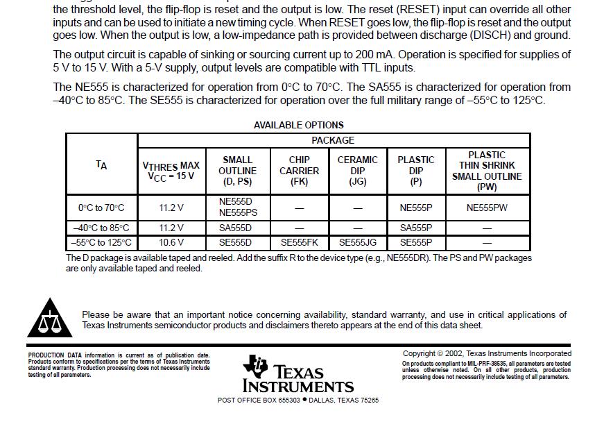
33 Capacitor C 1 is a shunt capacitor filter. The minimum capacitor that could be used was determined from the equation (4.4): Vdc = (4.4) With V P = 21.2, I dc = 200mA, f = 50Hz. The value of C can be found by substitution which is 114µf. The value used was 470µf with a voltage rating of 35V Control circuit Figure 4.3 Control circuit The control circuit comprises of an astable multi-vibrator (555 timer) which generates a high frequency (2 KHz) pulsating signal, a voltage comparator (LM393N) and a triac optical coupler (MOC3020). The 555 timer is rated 15V maximum. The values of R 1 and R 2 were found from the equation (4.5a) f =. (4.5a) with f = 2 KHz C 2 (R 1 +2R 2 ) = 28
34 Setting C 2 to be 10nf, then R 1 + 2R 2 = 72.5KΩ (4.5b) To obtain a square wave signal, R 2 should be greater than R 1. Hence setting R 1 to 6.8 KΩ, substitution in equation (4.5b) gives R 2 = 33K Ω. The data sheet recommends that voltage control terminal be connected to ground via a 10nf decoupling capacitor C 3 = 10nf. R 3 and D 5 set a reference voltage. A reference voltage of 12V is set by the zener diode D 5. D 5 is BZX79C12 rated V z = 12V and I z = 5mA. R 3 = = Hence R 3 design is 680Ω. = 600Ω R 4, R 5 and R 6 sample the output voltage to the motor. The voltage drop across R 6 and R 5 at 110V (this is the rated voltage of the dc motor), should be equal to the reference voltage (12V). 110V 12V (4.6a) 0.11 (4.6b) To get the maximum voltage output the variable resistor (R 6 ) is set at a minimum (zero) hence equation (4.6b) becomes: 0.11 R 5 = 0.11(R 4 + R 5 ) Setting R 4 = 470KΩ then R 5 = 56 KΩ. To attain a lower voltage, the value of the variable resistor (R 6 ) is increased. At a lower scale, to obtain a voltage of 50V: 29
35 50V = 12V (4.7a) = 0.24 (4.7b) By substitution R 6 = 87KΩ, Potentiometer available = 100KΩ The triac optical coupler is used to allow the pulse from the 555 timer to the inverter when the voltage drop across resistors R 5 and R 6 is less than the reference voltage. The optical coupler MOC3020 rated I f 15mA. Therefore the resistor R 7 has a value of 1KΩ. R 7 = (4.8) = = 1 KΩ DC AC Converter This employs a push-pull configuration having a high frequency coupling transformer Tx 2. Figure 4.4 DC- AC Converter 30
36 The transformer which is centre tapped at the primary is fed from the input rectifier made up of diodes D 6, D 7, D 8 and D 9. The diodes used were determined by the maximum voltage across each diode. V P = =339V. The output current = 9A. Output power = Output Voltage Output Current Supply current = = 110V 9A = 990VA = = 4.125A C 4 is the shunt capacitor filter. Its value was determined by substitution in equation (4.4). A capacitor of 330µf and voltage rating of 470V was used. The MOSFETs Q 4 and Q 5 are IRF740 rated 10A and 400V V DS max. Transistors Q 2 and Q 3 should be rated more than 100mA. Transistor 2N2907 rated 600mA was used. Resistors R 12 and R 16 were used to ground all leakage currents flowing through the transistors. R 12, R 16 = = = 150Ω R 9, R 14 = I B = = = 1mA Therefore; R 9, R 14 = = 15KΩ 31
37 The current flowing through the base of Q 3 is the collector current flowing through Q 1. The transistor C1815 rated 100mA and h fe 100 was used for Q 1. R 13 = R 10 = = = 15KΩ I B = = = 10µA R 10 = = 1.5MΩ Rectifier and filter This consists of full-wave bridge rectifier and L-C filter. Figure 4.5 Output rectifier 32
 0.01 = 1.19 LC LC = 0.0084 Selecting an inductance of 22µH for L, C =.")
38 Diodes D 10, D 11, D 12 and D 13 form a full-wave bridge rectifier. The diodes used are determined by the maximum voltage across each diode. The diodes used were rated 800Vmax. The inductor L 1 and capacitor C 5 form the L-C filter. The filter should be such that the ripple factor is 1%. r = 1.19 LC (4.9) 0.01 = 1.19 LC LC = Selecting an inductance of 22µH for L, C =. = 382µf Therefore a capacitance of 470µf with a voltage rating of 250V was chosen. The figure 4.6 shows the constructional details of the inverter drive. Figure 4.6 inverter drive designed 33
39 4.3 RESULTS AND ANALYSIS The inverter drive designed was able to produce dc voltage at the output that could be varied, to be supplied to the dc motor armature. Hence the control was by armature voltage control. The different values of dc voltage were provided for by the variable resistor R 6 (see figure 4.1). On the final packaged device the resistor knob was evenly divided in five divisions, i.e. from dial setting 0 to dial setting 5. Dial setting 0 represented the minimum resistance i.e. zero hence highest value of voltage at the output. Dial setting 5 represented the highest value of resistance i.e. 100KΩ hence the lowest value of voltage available at the output. The results expected (theoretical) and measured were tabulated in table 4.1. Table 4.1 Output Voltages Theoretical and Measured Dial Setting Output Voltage, V dc (Theoretical) Output Voltage, V dc (Measured) The measured voltages were slightly higher than the expected (theoretical) values. This could be explained due to the fact that on design from calculation, the components such as resistors calculated were not always the standard values of resistors available. The values of such components implemented were chosen to the nearest value. 34
40 The results (table 4.1) show that the circuit implemented could be used as an inverter drive for a dc motor. This could be used in situations where varying values of dc voltage are required but what is available from the supply is 240 V ac mains supply. The tabulated results also show that the inverter drive is capable of providing voltage of between 50V dc to 125V dc. 35
41 CHAPTER 5: CONCLUSION From the results obtained (table 4.1), the circuit designed was capable of providing speed control of a dc motor by producing varying dc voltage of between 50V and 125V. This dc voltage being supplied to the armature winding of the dc motor. A survey of the control of dc motors by conventional methods was carried out and the three main methods of control i.e. Varying the flux per pole Varying the resistance of the armature circuit. Varying the applied voltage were studied as required in the objectives of the project. The implementation of the project provided valuable knowledge of dc motors in general and how their control is useful in the industrial field. It also gave a good understanding of the conventional control concepts used in the control of dc motors. 5.1 RECOMMENDATIONS AND FURTHER WORK 1. Diodes should be added to the existing diodes (D 10, D 11, D 12 and D 13 ) in parallel hence enable the device handle more current and a motor with a bigger power rating. 2. The circuit could be further improved by implementing one that controls a specific dc motor, such that the output voltage of the inverter drive and the corresponding speed of the dc motor monitored. A digital display can hence be provided for showing the voltage and exact speed of the dc motor. 36
42 REFERENCES 1. Rudolf F. Graf, Williams Sheets, The Encyclopedia of Electronic Circuits Vol.4, 1992 McGraw-Hill Professional 2. V.K Mehta, Rohit Mehta, Principles of Electrical Machines, 2002 S.Chand & Company Ltd. 7361, Ram Nagar, New Delhi , Printed by Rajenda Ravindra Printers (Pvt.) Ltd., 7361, Ram Nagar New Delhi B. L. Theraja, A Textbook of Electrical Technology, 2005 S. Chand & Company Ltd. 7361, Ram Nagar, New Delhi , Printed by Rajenda Ravindra Printers (Pvt.) Ltd., 7361, Ram Nagar New Delhi S K Bhattacharya, S Chatterjee, Industrial Electronics & Control, 1995 Tata McGraw- Hill 5. Hughes Austin, Electric Motors and Drives: Fundamentals, types and applications, 1990 Newnes, Printed by Biddles Ltd 37
43 APPENDIX : DATA SHEETS 38

44 39
45 40
46 41
47 42
48 43
49 44
EE6351 ELECTRIC DRIVES AND CONTROL UNIT-1 INTRODUTION
 EE6351 ELECTRIC DRIVES AND CONTROL UNIT-1 INTRODUTION 1. What is meant by drive and electric drive? Machines employed for motion control are called drives and may employ any one of the prime movers for
CHAPTER THREE DC MOTOR OVERVIEW AND MATHEMATICAL MODEL
 CHAPTER THREE DC MOTOR OVERVIEW AND MATHEMATICAL MODEL 3.1 Introduction Almost every mechanical movement that we see around us is accomplished by an electric motor. Electric machines are a means of converting
UNIT 2. INTRODUCTION TO DC GENERATOR (Part 1) OBJECTIVES. General Objective
 OBJECTIVES. General Objective") DC GENERATOR (Part 1) E2063/ Unit 2/ 1 UNIT 2 INTRODUCTION TO DC GENERATOR (Part 1) OBJECTIVES General Objective : To apply the basic principle of DC generator, construction principle and types of DC generator.
DC GENERATOR (Part 1) E2063/ Unit 2/ 1 UNIT 2 INTRODUCTION TO DC GENERATOR (Part 1) OBJECTIVES General Objective : To apply the basic principle of DC generator, construction principle and types of DC generator.
EEE3441 Electrical Machines Department of Electrical Engineering. Lecture. Introduction to Electrical Machines
 Department of Electrical Engineering Lecture Introduction to Electrical Machines 1 In this Lecture Induction motors and synchronous machines are introduced Production of rotating magnetic field Three-phase
INSTITUTE OF AERONAUTICAL ENGINEERING Dundigal, Hyderabad
 INSTITUTE OF AERONAUTICAL ENGINEERING Dundigal, Hyderabad - 500 043 MECHANICAL ENGINEERING ASSIGNMENT Name : Electrical and Electronics Engineering Code : A40203 Class : II B. Tech I Semester Branch :
2. Draw the speed-torque characteristics of dc shunt motor and series motor. (May2013) (May 2014)
 (May 2014)") UNIT 2 - DRIVE MOTOR CHARACTERISTICS PART A 1. What is meant by mechanical characteristics? A curve is drawn between speed-torque. This characteristic is called mechanical characteristics. 2. Draw the
UNIT 2 - DRIVE MOTOR CHARACTERISTICS PART A 1. What is meant by mechanical characteristics? A curve is drawn between speed-torque. This characteristic is called mechanical characteristics. 2. Draw the
R13 SET - 1. b) Describe different braking methods employed for electrical motors. [8M]
![R13 SET - 1. b) Describe different braking methods employed for electrical motors. [8M]](/thumbs/89/100786446.jpg "R13 SET - 1. b) Describe different braking methods employed for electrical motors. [8M]") Code No:RT32026 R13 SET - 1 III B. Tech II Semester Regular Examinations, April - 2016 POWER SEMICONDUCTOR DRIVES (Electrical and Electronics Engineering) Time: 3 hours Maximum Marks: 70 Note: 1. Question
Code No:RT32026 R13 SET - 1 III B. Tech II Semester Regular Examinations, April - 2016 POWER SEMICONDUCTOR DRIVES (Electrical and Electronics Engineering) Time: 3 hours Maximum Marks: 70 Note: 1. Question
Most home and business appliances operate on single-phase AC power. For this reason, singlephase AC motors are in widespread use.
 Chapter 5 Most home and business appliances operate on single-phase AC power. For this reason, singlephase AC motors are in widespread use. A single-phase induction motor is larger in size, for the same
Principles of Electrical Engineering
 D.C GENERATORS Principle of operation of D.C machines, types of D.C Generators, e.m.f equation of D.C Generator, O.C.C of a D.C Shunt Generator, Load characteristics of D.C.Generators GENERATOR PRINCIPLE:
DEPARTMENT OF EI ELECTRICAL MACHINE ASSIGNMENT 1
 It is the mark of an educated mind to be able to entertain a thought without accepting it. DEPARTMENT OF EI ELECTRICAL MACHINE ASSIGNMENT 1 1. Explain the Basic concepts of rotating machine. 2. With help
 APGENCO/APTRANSCO Assistant Engineer Electrical Previous Question Papers Q.1 The two windings of a transformer is conductively linked. inductively linked. not linked at all. electrically linked. Q.2 A
2 Principles of d.c. machines
 2 Principles of d.c. machines D.C. machines are the electro mechanical energy converters which work from a d.c. source and generate mechanical power or convert mechanical power into a d.c. power. These
Part- A Objective Questions (10X1=10 Marks)
") Dr. Mahalingam College of Engineering and Technology, Pollachi-3 (An Autonomous Institution) CCET 3(2016Regulation) Name of Programme: B.E. (EEE) Course Code&Course Title: 16EET41 & Synchronous & Induction
Dr. Mahalingam College of Engineering and Technology, Pollachi-3 (An Autonomous Institution) CCET 3(2016Regulation) Name of Programme: B.E. (EEE) Course Code&Course Title: 16EET41 & Synchronous & Induction
Electric Motors. Presentation from the Energy Efficiency Guide for Industry in Asia
 Electric Motors Presentation from the Energy Efficiency Guide for Industry in Asia www.energyefficiencyasia.org Adapted by Prof Elisete Ternes Pereira To the UNIVERSITY OF NIZWA ١ Electric Motors Introduction
2014 ELECTRICAL TECHNOLOGY
 SET - 1 II B. Tech I Semester Regular Examinations, March 2014 ELECTRICAL TECHNOLOGY (Com. to ECE, EIE, BME) Time: 3 hours Max. Marks: 75 Answer any FIVE Questions All Questions carry Equal Marks ~~~~~~~~~~~~~~~~~~~~~~~~~~
St.MARTIN S ENGINEERING COLLEGE Dhulapally, Secunderabad
 St.MARTIN S ENGINEERING COLLEGE Dhulapally, Secunderabad-500 014 Subject: STATIC DRIVES Class : EEE III TUTORIAL QUESTION BANK Group I QUESTION BANK ON SHORT ANSWER QUESTION UNIT-I 1 What is meant by electrical
AC MOTOR TYPES. DESCRIBE how torque is produced in a single-phase AC motor. EXPLAIN why an AC synchronous motor does not have starting torque.
 Various types of AC motors are used for specific applications. By matching the type of motor to the appropriate application, increased equipment performance can be obtained. EO 1.5 EO 1.6 EO 1.7 EO 1.8
INTRODUCTION Principle
 DC Generators INTRODUCTION A generator is a machine that converts mechanical energy into electrical energy by using the principle of magnetic induction. Principle Whenever a conductor is moved within a
Institute of Technology, Nirma University B. Tech. Sem. V: Electrical Engineering 2EE305: ELECTRICAL MACHINES II. Handout: AC Commutator Motors
 Institute of Technology, Nirma University B. Tech. Sem. V: Electrical Engineering 2EE305: ELECTRICAL MACHINES II Handout: AC Commutator Motors Prepared by: Prof. T. H. Panchal Learning Objective: Introduction
Pretest Module 21 Units 1-4 AC Generators & Three-Phase Motors
 Pretest Module 21 Units 1-4 AC Generators & Three-Phase Motors 1. What are the two main parts of a three-phase motor? Stator and Rotor 2. Which part of a three-phase squirrel-cage induction motor is a
 VALLIAMMAI ENGINEERING COLLEGE MECHANICAL ENGINEERING ANNA UNIVERSITY CHENNAI II YEAR MECH / III SEMESTER EE6351 - ELECTRICAL DRIVES AND CONTROL (REGULATION 2013) UNIT I INTRODUCTION PART-A (2 MARKS) 1.
Single Phase Induction Motors
 Single Phase Induction Motors Prof. T. H. Panchal Asst. Professor Department of Electrical Engineering Institute of Technology Nirma University, Ahmedabad Introduction As the name suggests, these motors
The Wound-Rotor Induction Motor Part I
 Experiment 1 The Wound-Rotor Induction Motor Part I OBJECTIVE To examine the construction of the three-phase wound-rotor induction motor. To understand exciting current, synchronous speed and slip in a
FATIMA MICHAEL COLLEGE OF ENGINEERING & TECHNOLOGY Senkottai Village, Madurai Sivagangai Main Road, Madurai
 Department of Mechanical Engineering QUESTION BANK SUBJECT NAME: ELECTRICAL DRIVES AND CONTROL YEAR / SEM: II / III UNIT I INTRODUCTION PART-A (2 MARKS) 1. Define Drives 2. Define Electric Drives. 3. What
1.1 Block Diagram of Drive Components of Electric Drive & their functions. Power Processor / Modulator. Control. Unit
 Introduction Motion control is required in large number of industrial and domestic applications like transportations, rolling mills, textile machines, fans, paper machines, pumps, washing machines, robots
MEBS Utilities services Department of Electrical & Electronic Engineering University of Hong Kong
 Brief comparison of induction motors with other types of motors Electric motors exhibit wide variations of speed-torque characteristics. [Adopted from EL-SHARKAWI, Mohamed A., Fundamentals of Electric
Historical Development
 TOPIC 3 DC MACHINES DC Machines 2 Historical Development Direct current (DC) motor is one of the first machines devised to convert electrical power into mechanical power. Its origin can be traced to the
14 Single- Phase A.C. Motors I
 Lectures 14-15, Page 1 14 Single- Phase A.C. Motors I There exists a very large market for single-phase, fractional horsepower motors (up to about 1 kw) particularly for domestic use. Like many large volume
Synchronous Motor Drives
 UNIT V SYNCHRONOUS MOTOR DRIVES 5.1 Introduction Synchronous motor is an AC motor which rotates at synchronous speed at all loads. Construction of the stator of synchronous motor is similar to the stator
BELT-DRIVEN ALTERNATORS
 CHAPTER 13 BELT-DRIVEN ALTERNATORS INTRODUCTION A generator is a machine that converts mechanical energy into electrical energy using the principle of magnetic induction. This principle is based on the
Electrical Machines-I (EE-241) For S.E (EE)
 For S.E (EE)") PRACTICAL WORK BOOK For Academic Session 2013 Electrical Machines-I (EE-241) For S.E (EE) Name: Roll Number: Class: Batch: Department : Semester/Term: NED University of Engineer ing & Technology Electrical
PRACTICAL WORK BOOK For Academic Session 2013 Electrical Machines-I (EE-241) For S.E (EE) Name: Roll Number: Class: Batch: Department : Semester/Term: NED University of Engineer ing & Technology Electrical
DHANALAKSHMI COLLEGE OF ENGINEERING DEPARTMENT OF MECHANICAL ENGINEERING ME 6351 ELECTRICAL DRIVES AND CONTROL UNIVERSITY QUESTIONS AND ANSWERS
 DHANALAKSHMI COLLEGE OF ENGINEERING DEPARTMENT OF MECHANICAL ENGINEERING ME 6351 ELECTRICAL DRIVES AND CONTROL UNIVERSITY QUESTIONS AND ANSWERS 1) What is the Necessity of starter? UNIT 3 Two Marks Both
9/7/2010. Chapter , The McGraw-Hill Companies, Inc. MOTOR CLASSIFICATION. 2010, The McGraw-Hill Companies, Inc.
 Chapter 2 MOTOR CLASSIFICATION 1 In general, motors are classified according to the type of power used (AC or DC) and the motor's principle of operation. AC DC Motor Family Tree 2 DC MOTOR CONNECTIONS
INSTITUTE OF AERONAUTICAL ENGINEERING (Autonomous) Dundigal, Hyderabad DEPARTMENT OF ELECTRICAL AND ELECTRONICS ENGINEERING
 Dundigal, Hyderabad DEPARTMENT OF ELECTRICAL AND ELECTRONICS ENGINEERING") Course Name Course Code Class Branch INSTITUTE OF AERONAUTICAL ENGINEERING (Autonomous) Dundigal, Hyderabad - 500 0 DEPARTMENT OF ELECTRICAL AND ELECTRONICS ENGINEERING : Static Drives : A60225 : III -
Course Name Course Code Class Branch INSTITUTE OF AERONAUTICAL ENGINEERING (Autonomous) Dundigal, Hyderabad - 500 0 DEPARTMENT OF ELECTRICAL AND ELECTRONICS ENGINEERING : Static Drives : A60225 : III -
Renewable Energy Systems 13
 Renewable Energy Systems 13 Buchla, Kissell, Floyd Chapter Outline Generators 13 Buchla, Kissell, Floyd 13-1 MAGNETISM AND ELECTROMAGNETISM 13-2 DC GENERATORS 13-3 AC SYNCHRONOUS GENERATORS 13-4 AC INDUCTION
SQA Advanced Unit specification: general information
 SQA Advanced Unit specification: general information Unit title: Electrical Machine Principles Unit code: HT83 47 Superclass: XJ Publication date: August 2017 Source: Scottish Qualifications Authority
SHRI ANGALAMMAN COLLEGE OF ENGINEERING AND TECHNOLOGY (An ISO 9001:2008 Certified Institution) SIRUGANOOR, TIRUCHIRAPPALLI
 SIRUGANOOR, TIRUCHIRAPPALLI") SHRI ANGALAMMAN COLLEGE OF ENGINEERING AND TECHNOLOGY (An ISO 9001:2008 Certified Institution) SIRUGANOOR, TIRUCHIRAPPALLI 621 105 DEPARTMENT OF ELECTRICAL AND ELECTRONICS ENGINEERING EE1205 - ELECTRICAL
SHRI ANGALAMMAN COLLEGE OF ENGINEERING AND TECHNOLOGY (An ISO 9001:2008 Certified Institution) SIRUGANOOR, TIRUCHIRAPPALLI 621 105 DEPARTMENT OF ELECTRICAL AND ELECTRONICS ENGINEERING EE1205 - ELECTRICAL
SECTION 4 ELECTRIC MOTORS UNIT 17: TYPES OF ELECTRIC MOTORS UNIT OBJECTIVES UNIT OBJECTIVES 3/21/2012
 SECTION 4 ELECTRIC MOTORS UNIT 17: TYPES OF ELECTRIC MOTORS UNIT OBJECTIVES After studying this unit, the reader should be able to Describe the different types of open single-phase motors used to drive
UNIT-1 Drive Characteristics
 UNIT-1 Drive Characteristics DEFINITION: Systems employed for motion control are called as DRIVES Drives may employ any of the prime movers such as diesel or petrol engine, gas or steam turbines, steam
Armature Reaction and Saturation Effect
 Exercise 3-1 Armature Reaction and Saturation Effect EXERCISE OBJECTIVE When you have completed this exercise, you will be able to demonstrate some of the effects of armature reaction and saturation in
Universal motor From Wikipedia, the free encyclopedia
 Page 1 of 8 Universal motor From Wikipedia, the free encyclopedia The universal motor is so named because it is a type of electric motor that can operate on AC or DC power. It is a commutated serieswound
Pretest Module 21 Units 1-3 AC Generators & Three-Phase Motors
 Pretest Module 21 Units 1-3 AC Generators & Three-Phase Motors 1. What are the two main parts of a three-phase 2. Which part of a three-phase squirrel-cage induction motor is a hollow core? 3. What are
ROTATING MAGNETIC FIELD
 Chapter 5 ROTATING MAGNETIC FIELD 1 A rotating magnetic field is the key to the operation of AC motors. The magnetic field of the stator is made to rotate electrically around and around in a circle. Stator
EXPERIMENTAL VERIFICATION OF INDUCED VOLTAGE SELF- EXCITATION OF A SWITCHED RELUCTANCE GENERATOR
 EXPERIMENTAL VERIFICATION OF INDUCED VOLTAGE SELF- EXCITATION OF A SWITCHED RELUCTANCE GENERATOR Velimir Nedic Thomas A. Lipo Wisconsin Power Electronic Research Center University of Wisconsin Madison
PHY 152 (ELECTRICITY AND MAGNETISM)
") PHY 152 (ELECTRICITY AND MAGNETISM) ELECTRIC MOTORS (AC & DC) ELECTRIC GENERATORS (AC & DC) AIMS Students should be able to Describe the principle of magnetic induction as it applies to DC and AC generators.
PHY 152 (ELECTRICITY AND MAGNETISM) ELECTRIC MOTORS (AC & DC) ELECTRIC GENERATORS (AC & DC) AIMS Students should be able to Describe the principle of magnetic induction as it applies to DC and AC generators.
ESO 210 Introduction to Electrical Engineering
 ESO 210 Introduction to Electrical Engineering Lectures-37 Polyphase (3-phase) Induction Motor 2 Determination of Induction Machine Parameters Three tests are needed to determine the parameters in an induction
ELECTRIC MACHINES OPENLAB 0.2 kw
 THIS SYSTEM IS A COMPLETE SET OF COMPONENTS AND MODULES SUITABLE FOR ASSEMBLING THE ROTATING ELECTRIC MACHINES, BOTH FOR DIRECT CURRENT AND FOR ALTERNATING CURRENT. STUDENTS CAN PERFORM A CRITICAL AND
Single-Phase AC Induction Squirrel Cage Motors. Permanent Magnet Series Wound Shunt Wound Compound Wound Squirrel Cage. Induction.
 FAN ENGINEERING Information and Recommendations for the Engineer Twin City Fan FE-1100 Single-Phase AC Induction Squirrel Cage Motors Introduction It is with the electric motor where a method of converting
INDUCTION MOTOR. There is no physical electrical connection to the secondary winding, its current is induced
 INDUCTION MOTOR INTRODUCTION An induction motor is an alternating current motor in which the primary winding on one member (usually the stator) is connected to the power source and a secondary winding
Variable Speed Drives in Electrical Energy Management. Course Content
 Variable Speed Drives in Electrical Energy Management Course Content Introduction & Overview The basic equation for a 3 phase electric motor is: N = rotational speed of stator magnetic field in RPM (synchronous
Electrical Machines II. Week 5-6: Induction Motor Construction, theory of operation, rotating magnetic field and equivalent circuit
 Electrical Machines II Week 5-6: Induction Motor Construction, theory of operation, rotating magnetic field and equivalent circuit Asynchronous (Induction) Motor: industrial construction Two types of induction
CHAPTER 6 DESIGN AND DEVELOPMENT OF DOUBLE WINDING INDUCTION GENERATOR
 100 CHAPTER 6 DESIGN AND DEVELOPMENT OF DOUBLE WINDING INDUCTION GENERATOR 6.1 INTRODUCTION Conventional energy resources are not sufficient to meet the increasing electrical power demand. The usages of
10. Starting Method for Induction Motors
 10. Starting Method for Induction Motors A 3-phase induction motor is theoretically self starting. The stator of an induction motor consists of 3-phase windings, which when connected to a 3-phase supply
INTRODUCTION. I.1 - Historical review.
 INTRODUCTION. I.1 - Historical review. The history of electrical motors goes back as far as 1820, when Hans Christian Oersted discovered the magnetic effect of an electric current. One year later, Michael
Operation Construction Classification Applications. DC Motors
 Operation Construction Classification Applications DC Motors A DC Motor converts electrical energy into mechanical energy. Special applications where dc motors are used include: in steel mills, mines
Lecture 20: Stator Control - Stator Voltage and Frequency Control
 Lecture 20: Stator Control - Stator Voltage and Frequency Control Speed Control from Stator Side 1. V / f control or frequency control - Whenever three phase supply is given to three phase induction motor
Doubly fed electric machine
 Doubly fed electric machine Doubly fed electric machines are electric motors or electric generators that have windings on both stationary and rotating parts, where both windings transfer significant power
VIII. Three-phase Induction Machines (Asynchronous Machines) Induction Machines
 Induction Machines") VIII. Three-phase Induction Machines (Asynchronous Machines) Induction Machines 1 Introduction Three-phase induction motors are the most common and frequently encountered machines in industry simple design,
VIII. Three-phase Induction Machines (Asynchronous Machines) Induction Machines 1 Introduction Three-phase induction motors are the most common and frequently encountered machines in industry simple design,
CHAPTER 6 INTRODUCTION TO MOTORS AND GENERATORS
 CHAPTER 6 INTRODUCTION TO MOTORS AND GENERATORS Objective Describe the necessary conditions for motor and generator operation. Calculate the force on a conductor carrying current in the presence of the
Technical Guide No. 7. Dimensioning of a Drive system
 Technical Guide No. 7 Dimensioning of a Drive system 2 Technical Guide No.7 - Dimensioning of a Drive system Contents 1. Introduction... 5 2. Drive system... 6 3. General description of a dimensioning
Regulation: R16 Course & Branch: B.Tech EEE
 SIDDHARTH GROUP OF INSTITUTIONS :: PUTTUR Siddharth Nagar, Narayanavanam Road 517583 QUESTION BANK (Descriptive) Subject with Code : Electrical Machines-II (16EE215) Regulation: R16 Course & Branch: B.Tech
(d) None of the above.
 None of the above.") Dr. Mahalingam College of Engineering and Technology, Pollachi-3 (An Autonomous Institution affiliated to Anna niversity) CCET II (2016 Regulation) Name of Programme: B.E. (EEE) Course Code & Course Title:
Dr. Mahalingam College of Engineering and Technology, Pollachi-3 (An Autonomous Institution affiliated to Anna niversity) CCET II (2016 Regulation) Name of Programme: B.E. (EEE) Course Code & Course Title:
Electrical Machines and Energy Systems: Overview SYED A RIZVI
 Electrical Machines and Energy Systems: Overview SYED A RIZVI Electrical Machines and Energy Systems Deal with the generation, transmission & distribution, and utilization of electric power. This course
Single Phase Induction Motor. Dr. Sanjay Jain Department Of EE/EX
 Single Phase Induction Motor Dr. Sanjay Jain Department Of EE/EX Application :- The single-phase induction machine is the most frequently used motor for refrigerators, washing machines, clocks, drills,
AC Motors vs DC Motors. DC Motors. DC Motor Classification ... Prof. Dr. M. Zahurul Haq
 AC Motors vs DC Motors DC Motors Prof. Dr. M. Zahurul Haq http://teacher.buet.ac.bd/zahurul/ Department of Mechanical Engineering Bangladesh University of Engineering & Technology ME 6401: Advanced Mechatronics
 DC MOTORS DC Motors DC Motor is a Machine which converts Electrical energy into Mechanical energy. Dc motors are used in steel plants, paper mills, textile mills, cranes, printing presses, Electrical locomotives
Note 8. Electric Actuators
 Note 8 Electric Actuators Department of Mechanical Engineering, University Of Saskatchewan, 57 Campus Drive, Saskatoon, SK S7N 5A9, Canada 1 1. Introduction In a typical closed-loop, or feedback, control
5. The force required to bring an object weighing 65 lb from rest to a speed of 50 fps in 10 sec is approximately
 Student ID: 53703105 Exam: 4341RR - Industrial Motor Applications When you have completed your exam and reviewed your answers, click Submit Exam. Answers will not be recorded until you hit Submit Exam.
Unit III-Three Phase Induction Motor:
 INTRODUCTION Unit III-Three Phase Induction Motor: The three phase induction motor runs on three phase AC supply. It is an ac motor. The power is transferred by means of induction. So it is also called
Contents. Review of Electric Circuitd. Preface ;
 Preface ; Chapter 1 Review of Electric Circuitd 1.1 Introduction, 1 1.2 Direct Circuit Current, 1 1.2.1 Voltage, 3 1.2.2 Power, 3 1.2.3 Ohm's Law, 5 1.2.4 KirchhofTs Laws, 5 1.2.4.1 Kirchhoff s Current
Application Note CTAN #127
 Application Note CTAN #127 Guidelines and Considerations for Common Bus Connection of AC Drives An important advantage of AC drives with a fixed DC is the ability to connect the es together so that energy
COLLEGE OF ENGINEERING DEPARTMENT OF ELECTRICAL AND ELECTRONICS ENGINEERING QUESTION BANK SUBJECT CODE & NAME : EE 1001 SPECIAL ELECTRICAL MACHINES
 KINGS COLLEGE OF ENGINEERING DEPARTMENT OF ELECTRICAL AND ELECTRONICS ENGINEERING QUESTION BANK SUBJECT CODE & NAME : EE 1001 SPECIAL ELECTRICAL MACHINES YEAR / SEM : IV / VII UNIT I SYNCHRONOUS RELUCTANCE
Electricity Course. Part B Course Outline
 Electricity Course Rev. Date: 10/01/2002 By: R. Crompton Part B Course Outline Subject Area 0 Orientation 2.6 0.0 0.1 To the School 1.0 0.2 To the Course 1.0 0.3 To the 0.3 0.3 0.4 To Possible Emergencies
DEPARTMENT OF ELECTRICAL AND ELECTRONICS ENGINEERING
 DEPARTMENT OF ELECTRICAL AND ELECTRONICS ENGINEERING QUESTION BANK 16EET41 SYNCHRONOUS AND INDUCTION MACHINES UNIT I SYNCHRONOUS GENERATOR 1. Why the stator core is laminated? 2. Define voltage regulation
Unit 34 Single-Phase Motors
 Unit 34 Single-Phase Motors Objectives: Unit 34 Single-Phase Motors List the different types of split-phase motors. Discuss the operation of split-phase motors. Reverse the direction of rotation of a splitphase
Motor Basics AGSM 325 Motors vs Engines
 Motor Basics AGSM 325 Motors vs Engines Motors convert electrical energy to mechanical energy. Engines convert chemical energy to mechanical energy. 1 Motors Advantages Low Initial Cost - $/Hp Simple &
DC motor theory. Resources and methods for learning about these subjects (list a few here, in preparation for your research):
:") DC motor theory This worksheet and all related files are licensed under the Creative Commons Attribution License, version 1.0. To view a copy of this license, visit http://creativecommons.org/licenses/by/1.0/,
DC motor theory This worksheet and all related files are licensed under the Creative Commons Attribution License, version 1.0. To view a copy of this license, visit http://creativecommons.org/licenses/by/1.0/,
CHAPTER 4 MODELING OF PERMANENT MAGNET SYNCHRONOUS GENERATOR BASED WIND ENERGY CONVERSION SYSTEM
 47 CHAPTER 4 MODELING OF PERMANENT MAGNET SYNCHRONOUS GENERATOR BASED WIND ENERGY CONVERSION SYSTEM 4.1 INTRODUCTION Wind energy has been the subject of much recent research and development. The only negative
Unit 32 Three-Phase Alternators
 Unit 32 Three-Phase Alternators Objectives: Discuss the operation of a three-phase alternator. Explain the effect of rotation speed on frequency. Explain the effect of field excitation on output voltage.
Circuit Diagram For Speed Control Of Slip Ring Induction Motor
 Circuit Diagram For Speed Control Of Slip Ring Induction Motor A wound-rotor motor is a type of induction motor where the rotor windings are Compared to a squirrel-cage rotor, the rotor of the slip ring
TWO MARK QUESTIONS-ANSWERS
 TWO MARK QUESTIONS-ANSWERS DEPARTMENT: MECH SEMESTER : III SUBJECT CODE: ME2205 SUBJECT NAME: ELECTRIC DRIVES & CONTROL 1. Define Drive and Electric Drive. Drive: A particular system employed for motion
SSC-JE STAFF SELECTION COMMISSION ELECTRICAL ENGINEERING STUDY MATERIAL ELECTRICAL MACHINES
 1 SSC-JE STAFF SELECTION COMMISSION ELECTRICAL ENGINEERING STUDY MATERIAL 28-B/7, Jia Sarai, Near IIT, Hauz Khas, New Delhi-110016. Ph. 011-26514888. www.engineersinstitute.com 2 CONTENT 1. : DC MACHINE,
Código de rotor bloqueado Rotor bloqueado, Letra de código. Rotor bloqueado, Letra de código
 Letra de código Código de rotor bloqueado Rotor bloqueado, Letra de código kva / hp kva / hp A 0.00 3.15 L 9.00 10.00 B 3.15 3.55 M 10.00 11.00 C 3.55 4.00 N 11.00 12.50 D 4.00 4.50 P 12.50 14.00 E 4.50
AE105 PRINCIPLES OF ELECTRICAL ENGINEERING JUNE 2014
 Q.2 a. Explain in detail eddy current losses in a magnetic material. Explain the factors on which it depends. How it can be reduced? IETE 1 b. A magnetic circuit with a single air gap is shown in given
Mechatronics Chapter 10 Actuators 10-3
 MEMS1049 Mechatronics Chapter 10 Actuators 10-3 Electric Motor DC Motor DC Motor DC Motor DC Motor DC Motor Motor terminology Motor field current interaction Motor commutator It consists of a ring of
General Purpose Permanent Magnet Motor Drive without Speed and Position Sensor
 General Purpose Permanent Magnet Motor Drive without Speed and Position Sensor Jun Kang, PhD Yaskawa Electric America, Inc. 1. Power consumption by electric motors Fig.1 Yaskawa V1000 Drive and a PM motor
ELECTRIC MACHINES EUROLAB 0.3 kw
 index SINGLE-PHASE MOTORS SPLIT-PHASE MOTOR DL 30130 CAPACITOR MOTOR DL 30140 UNIVERSAL MOTOR DL 30150 REPULSION MOTOR DL 30170 THREE PHASE ASYNCHRONOUS MOTORS SQUIRREL CAGE THREE PHASE ASYNCHRONOUS MOTOR
PI Electrical Equipment - Course PI 30.2 MOTORS
 Electrical Equipment - Course PI 30.2 MOTORS OBJECTIVES On completion of this module the student will be able to: 1. Briefly explain, in writing, "shaft rotation" as an interaction of stator and rotor
DC CIRCUITS ELECTROMAGNETISM
 DC CIRCUITS 1. State and Explain Ohm s Law. Write in brief about the limitations of Ohm s Law. 2. State and explain Kirchhoff s laws. 3. Write in brief about disadvantages of series circuit and advantages
Application Note : Comparative Motor Technologies
 Application Note : Comparative Motor Technologies Air Motor and Cylinders Air Actuators use compressed air to move a piston for linear motion or turn a turbine for rotary motion. Responsiveness, speed
Lecture 2. Power semiconductor devices (Power switches)
") Lecture 2. Power semiconductor devices (Power switches) Power semiconductor switches are the work-horses of power electronics (PE). There are several power semiconductors devices currently involved in
Lecture 2. Power semiconductor devices (Power switches) Power semiconductor switches are the work-horses of power electronics (PE). There are several power semiconductors devices currently involved in
DC Motor and Generator Theory By
 DC Principles Study Unit DC Motor and Generator Theory By Robert Cecci iii Preview DC motors and generators are widely used in industrial applications. Both motors and generators are devices that produce
A Practical Primer On Motor Drives (Part 11): AC And DC Motor Types
: AC And DC Motor Types") A Practical Primer On Motor Drives (Part 11): AC And DC Motor Types by Ken Johnson, Teledyne LeCroy, Chestnut Ridge, N.Y. ISSUE: December 2016 In the previous part in this series, the basic principles
A Practical Primer On Motor Drives (Part 11): AC And DC Motor Types by Ken Johnson, Teledyne LeCroy, Chestnut Ridge, N.Y. ISSUE: December 2016 In the previous part in this series, the basic principles
MAHARASHTRA STATE BOARD OF TECHNICAL EDUCATION (Autonomous) (ISO/IEC Certified)
 (ISO/IEC Certified)") Summer 2016 EXAMINATION Subject Code: 17667 Model Answer Important Instructions to examiners: 1) The answers should be examined by key words and not as word-to-word as given in the answer scheme. 2) The
Summer 2016 EXAMINATION Subject Code: 17667 Model Answer Important Instructions to examiners: 1) The answers should be examined by key words and not as word-to-word as given in the answer scheme. 2) The
Pre-lab Questions: Please review chapters 19 and 20 of your textbook
 Introduction Magnetism and electricity are closely related. Moving charges make magnetic fields. Wires carrying electrical current in a part of space where there is a magnetic field experience a force.
ELECTRICAL MAINTENANCE
 ELECTRICAL MAINTENANCE II PRACTICAL JOURNAL DATA 1 EXPERIMENT NO. 1 AIM: TO FIND VOLTAGE RATIO OF A GIVEN TRANSFORMER. CIRCUIT DIAGRAM: OBSERVATION TABLE: Sr.No. 1 2 3 4 Primary Voltage (V 1 ) Secondary
ELECTRIC DRIVES N.K. DE P.K. SEN
 ELECTRIC DRIVES N.K. DE P.K. SEN Electric Drives NISIT K. DE Associate Professor Department of Electrical Engineering Indian Institute of Technology Kharagpur and PRASANTA K. SEN Assistant Professor Department
Chapter 7: DC Motors and Transmissions. 7.1: Basic Definitions and Concepts
 Chapter 7: DC Motors and Transmissions Electric motors are one of the most common types of actuators found in robotics. Using them effectively will allow your robot to take action based on the direction
Prepared By: Ahmad Firdaus Bin Ahmad Zaidi
 Prepared By: Ahmad Firdaus Bin Ahmad Zaidi A stepper motor is an electromechanical device which converts electrical pulses into discrete mechanical rotational movements. Stepper motor mainly used when
ELECTRICITY: INDUCTORS QUESTIONS
 ELECTRICITY: INDUCTORS QUESTIONS No Brain Too Small PHYSICS QUESTION TWO (2017;2) In a car engine, an induction coil is used to produce a very high voltage spark. An induction coil acts in a similar way