2. Draw the speed-torque characteristics of dc shunt motor and series motor. (May2013) (May 2014)
|
|
|
- Stephany Parrish
- 6 years ago
- Views:
Transcription
1 UNIT 2 - DRIVE MOTOR CHARACTERISTICS PART A 1. What is meant by mechanical characteristics? A curve is drawn between speed-torque. This characteristic is called mechanical characteristics. 2. Draw the speed-torque characteristics of dc shunt motor and series motor. (May2013) (May 2014) 3. A series motor should never be started without some mechanical load why? When the load current Ia falls to a small value, speed becomes dangerously high. Hence a series motor should never be started without some mechanical load. 4. What is rheostatic braking? In rheostatic braking the armature is disconnected from the supply and is connected as a variable resistance. The braking is controlled by varying the series resistance. 5. What are the different types of dc motor? I. DC series motor 2. Shunt motor 3. Compound motor 4. Separately excited de motor 6. What is meant by electrical characteristics? A curve is drawn torque and armature current. characteristics. It is known as electrical 7. What is the relation between speed and flux of a dc motor? The speed of a dc motor is inversely proportional to field flux.
2 8. What is the application of dc motor? DC shunt motor:- 1. For driving constant speed operations 2. Machine tools 3. Lathes 4. Blowers and fans 5. Centrifugal pumps 6.Reciprocating pumps DC series motor:- 1.Electric locomotives 2. Rapid transit systems3.trolley cars4.cranes and hoists5. Conveyors DC compound motor:-1. Elevators.2. Air compressors3. Rolling mills4. Heavy planers 9. A dc shunt motor is called as constant speed motor-why? ( May 2015) The drop in speed from no-load full-load is small; hence the dc shunt motor is also called as constant speed motor. 10. What is mean by braking? Whenever an electric drive is disconnected from the supply, the speed of the driving motor gradually decreases and becomes zero. Braking is a generic term used to describe a set of operating conditions for electric drive systems. It includes rapid stopping of the electric motor holding the motor shaft to a specific position, maintaining the speed to a desired value of preventing the motor from over speeding. 11. What are the two types of braking? 1. Mechanical braking 2. Electrical braking 12. What is meant by mechanical braking? In mechanical braking, the frictional force between the rotating parts and brake drums provide the required brake. 13. What is meant by electric braking? In electric braking, the motor is made to work as generator. So it produces a negative slip and negative torque (braking torque). This is achieved by suitably changing the electrical connections of the motor. 14. What are the different types of electric braking?(nov2013)(may 2013) ( May 2015) 1. Regenerative braking 2. Dynamic braking 3. Plugging 15. What are the advantages of electric braking?
3 1. High efficient method 2. Low maintenance 3. Braking is very smooth 16. What is meant by regenerative braking? (Dec 2011) In the regenerative braking operation, the motor operators as a generator, while it is still connected to the supply. Here, the motor speed is greater than the synchronous speed. Mechanical energy is converted into electrical energy, part of which is returned to the supply and rest of the energy is last as heat in the winding and bearings. 17. What is meant by dynamic braking? When an electric motor rotates, a kinetic energy of the motor is converted into electric energy. This energy is dissipated in resistive elements. 18. What is meant by plugging? (Dec 2014) The plugging operation can be obtained by changing the polarity of the motor. For a machine, the phase sequence of the starter windings and dc machines the polarities of the field or armature terminals. 19. What are the disadvantages of dc machine? 1. Higher cost 2. Higher rotor inertia 3. EMI problems 4. Maintains problems with commutator and brushes 5. Do not permit a machine to operate in dirty and explosive environments. 20. What are the advantages of squirrel cage induction motor? 1. Rugged 2. Cheaper 3.Lighter 4.More efficient 5. Less maintenance6. Can operate in explosive and dirty environment. 21. What are the two types of rotors in three phase induction motors? 1. Squirrel cage rotor 2. Slip ring rotor 22.What is the necessity of braking?(dec 2014) The quickness and accuracy of braking techniques determine the productivity and quality of the manufactured goods.control the motor for our optimum requirement. 23.What are different methods of Braking of DC series motor? (Nov 2015) 1. Regenerative braking 2. Dynamic braking 3. Plugging
4 24. A 220V DC shunt motor having the armature current of 10A, runs at 1500 rpm. Find the armature current if the source voltage drops to 150V. Assume the load torque is constant.(nov 2015) Given, V1=220V, Ia1=10A, V2=150V, Ia2=?. For Shunt motor, Ia1Φ1= Ia2Φ2 (since torque is constant) Φ2=(150/220) Φ > Φ2=0.68 Φ1. Therefore, Ia2=(10 Φ1/0.68 Φ1) = 14.67A. PART B 1. Explain about the speed-torque characteristics of a DC Compound Motor with suitable graph and equations.(dec 2013) The DC motor that has both shunt as well as series field winding is known as DC compound Motor. If the flux produced by series field winding helps (aids) the flux produced by shunt field, then the total flux increases and DC compound motor is known as Cumulative Compound Moor. On the other hand, if the series field flux opposes the Shunt field flux, total flux decreases and the motor is known as Differential compound Motor. (N VsIa), (T VsIa) and (N Vs T) characteristics should be obtained. 2. Draw and explain the speed torque characteristics of dc series motor and three phase induction motor.(dec 2011) The DC motor in which the field winding is connected in series with Armature Conductors is known as DC series Motor. In series circuit the current flowing through the armature is same as the current flowing through series field winding. Since the full load armature current flow through series field, the magnetic saturation takes place (Flux don t increase with current after certain point ).(N VsIa), (T VsIa) and (N Vs T) characteristics should be obtained. 3. Explain about the speed-torque characteristics of a DC Shunt Motor with suitable graph and equations. (Dec 2014) Speed / Torque Characteristics of DC shunt Motor DC Shunt Motor The DC Motor is which in Field Winding is connected in Parallel with Armature conductors is known as DC Shunt motor since Field winding is connected in parallel with both supply and the armature, the voltage across the field winding is always constant. So the current flowing through the field winding and hence the flux produced in the DC shunt Motor is Constant.
5 (i) Speed / Current Characteristics (N VsIa) (ii) Torque / Current Characteistics (T VsIa ) (iii) Speed / Torque Characteristics ( NVs T)
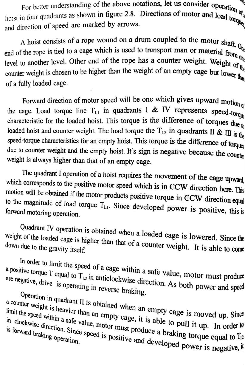
6 4. Explain about the quadrant diagram of speed-torque characteristics for a motor driving hoist load.(nov 2015) (May 2015) Theory : Explanation in detail for the 4 quadrant is needed.
7
8 5. Explain how an induction motor is brought to stop by (i) Plugging and (ii) dynamic braking. (Dec 2014) (a) Plugging or Reverse Current Braking of 3 Induction Motor Plugging incase of 3 induction motor is obtained by interchanging any of the two phases, out of the three phases. There are three phase terminals in 3 induction motor and it is represented by R, Y and B. The order in which, these phases progresses is known as Phase sequence. The phase sequence determines the direction of rotation and torque. The normal working induction motor is shown in Fig. The phase sequence applied is RYB and the motor rotates in Clockwise direction. The Plugging or Reverse Current Braking is obtained by interchanging supply phase terminals Y and B. Now the phase sequence is changed to RBY. The change is phase sequence from RYB to RYB changes the direction of current and hence the direction of rotating magnetic field. Due to this, direction of torque is reversed and this torque is known as Braking torque. The Braking torque reduced the speed of the motor to standstill. If the supply terminal is not disconnected at this stage, then the braking torque accelerates the motor in the anit clockwise direction. So plugging is accomplished by changing the supply terminals. The reverse current braking characteristic is shown in Fig.. It has two part namely normaly motoring zone before the application of plugging. The Slip = 0 corresponds to Synchronous speed Ns. The induction motor always runs at speed less than synchronous speed. When reverse current braking is applied the braking torque is generated and is shown as braking zone in Fig. The Speed reduced to zero i.e., n = 0 and the corresponding Slip, S = 1
9 b.dynamic or Rheostatic braking (3 Slip Ring Induction Motor) Rheostatic braking is not possible in case of squirrel cage induction motor and is only possible in the case of slip ring induction motor. Here braking is obtained by exciting any of the two stator phase with DC supply and rotor circuit is connected to star connected external rheostat. The braking is accomplished by disconnecting the stator form 3 supply and connecting any of the two phases with DC supply. Simultaneously external star connected rheostat is connected to the rotor circuit through slip rings. Now the start produced constant flux due to DC supply and the rotor is still rotating due to inertia. So emf is induced in the rotor and current flows in such a direction to oppose the cause (speed). So braking torque is produced that results in, stoppage of the motor. The principle of rheostatic braking can also arrived by the fact that the kinetic energy of rotating
10 mass is converted into electrical energy in rotor and it is wasted in star connected rheostat and the motor stops, because the kinetic energy is consumed. From the braking characteristics it is clear that braking torque become zero, when the motor is stopped i.e there is no holding torque. The magnitude of braking torque is varied by changing the resistance of the star connected rheostat. 6. Explain the various methods of braking of induction motors. (June 2014) Electrical braking Methods of AC motor (Induction motor) The braking methods that are applied to DC motors are also applied to AC motors, particularly 3 induction motor. The braking methods are 1. Plugging or Reverse Current Braking 2. Dynamic or Rheostatic Braking and 3. Regenerative Braking 7. Describe the speed Torque characteristics of DC Dynamic braking of three phase induction motor. (May 2014)
11 Rheostatic braking is not possible in case of squirrel cage induction motor and is only possible in the case of slip ring induction motor. Here braking is obtained by exciting any of the two stator phase with DC supply and rotor circuit is connected to star connected external rheostat. The braking is accomplished by disconnecting the stator form 3 supply and connecting any of the two phases with DC supply. Simultaneously external star connected rheostat is connected to the rotor circuit through slip rings. Now the start produced constant flux due to DC supply and the rotor is still rotating due to inertia. So emf is induced in the rotor and current flows in such a direction to oppose the cause (speed). So braking torque is produced that results in, stoppage of the motor. The principle of rheostatic braking can also arrived by the fact that the kinetic energy of rotating mass is converted into electrical energy in rotor and it is wasted in star connected rheostat and the motor stops, because the kinetic energy is consumed. From the braking characteristics it is clear that braking torque become zero, when the motor is stopped i.e there is no holding torque. The magnitude of braking torque is varied by changing the resistance of the star connected rheostat.
12 8. Explain speed- torque characteristics of different types of load with graph.(may 2013) N Vs T characteristics of shunt, series and compound motor should be explained. 9. A 220 V dc series motor runs at1200 rpm (clockwise) and takes an armature current of 80 A when driving a load with constant torque. Armature resistance is 0.05Ω and field resistance is 0.05Ω. Find the magnitude and direction of motor speed and armature current if the motor terminal voltage is reversed and number of turns in field winding is reduced to 80%. Assume linear magnetic circuit. (Dec 2013) Answer: Direction of current is anticlockwise. Eb1 = 212V; Ia2 = 100A; Eb2 = 210V; N2 = 1485 rpm. 10. Explain various methods of braking of DC Series Motors with neat diagrams.(may 2013) The DC motor in which the field winding is connected in series with Armature Conductors is known as DC series Motor. In series circuit the current flowing through the armature is same as the current flowing through series field winding. Since the full load armature current flow through series field, the magnetic saturation takes place (Flux don t increase with current after certain point ). (N VsIa), (T VsIa) and (N Vs T) characteristics should be obtained. 11.Discuss the dynamic braking of DC shunt motor. (Nov 2015) Rheostatic or Dynamic Braking Rheostatic braking of DC motor is obtained by disconnecting the armature terminals from the supply and connecting it to the external resistance R. The field winding is not disturbed. Rheostatic Braking of DC shunt Motor The armature terminals are disconnected from the supply and connected to external resistance R. now the armature current direction is reversed. Due to this reversed current direction the torque is produced in the opposite direction. Which is known as braking torque. Now the armature generates voltage and hence acts as a separately exited generator. The kinetic energy of the moving system is converted into electrical
13 energy, which is dissipated in the external resistance R. Here the motor is braked by generated action. The connection diagram for Rheostatic braking of DC shunt motor shown below. 12. List the advantages and disadvantages of Electrical braking over mechanical braking. Discuss any one method of electrical braking of DC machines.(may 2015)

14 Electrical Braking methods for DC motor. The Electrical braking is applied to DC motor by generating the electrical braking torque. The braking torque is obtained by just changing some of the electrical connection of the electric motor. In electric braking the drive motor itself methods available, they are 1. Plugging or reverse current or counter current 2. Rheostatic braking 3.Regenerative braking Plugging in DC Series motor The reverse current braking of series motor is obtained by reversing the armature terminals. Due to reversal of armature terminals, the direction of the armature current is reversed. Enough care should be taken to ensure that the field current is not reversed. This is because in series motor armature and series field are in the same circuit. The braking torque is produced due to reversal of armature current. To limit the over current during braking an external resistance R is included in the armature current. The Plugging is also done in series motor by separately existing the series field winding.
15 Rheostatic braking of DC series Motor The Rheostatic braking of DC series motor is shown. Here armature and field winding present in the same circuit. Rheostatic Braking is obtained by disconnecting the armature circuit form the supply and connected to external resistance R. Now armature current is reversed. Since this is series motor, the field current is also reversed (armature current is also the field current). This leads to demagnetization of field circuit, as a result generator action do not takes place. To avoid this, field terminals (f1, f2) are reversed when armature circuit is connected to the external resistance R. Now motor acts as a generator and as the a result, kinetic energy of the moving system is converted to the electrical energy and wasted in the resistance R. Since the kinetic energy of the moving system is wasted, Braking torque is produced. Regenerative braking of DC series Motor In series motor the armature and the field, both present in the san circuit. Here the armature current is equal to the field current. When the over hauling load increase the speed of the DC motor, the back emf also increase. So the current also flow through the field windings the flux is also decreases. Due to decrease in flux, it is clear that the back emf never exceeds the supply voltage. So there is no possibility of motor entering into the generating mode. So there is no chance of regenerative braking torque. It is clear from the above discussion that Regenerative braking is not possible in case of DC series motor. The DC series motor in practice is subjected to over hauling loads, as in the case of hoist (lowering load) and traction (when descending the mountain). So the regenerative braking can be obtained in the DC series motor by separately exciting the series field winding. This method of separately exciting DC series motor to obtain
16 Regenerative braking. Now the Back emf (Eb) exceeds the supply voltage (V), as a result the machine enters into generating mode. The current direction is reversed now (towards the supply mains), as a result regenerative braking torque is produced, due to magnetic drag associated with generating mode. The speed of the machine is reduced till it reaches the rated no load speed. When the speed of the machine reaches rated no load speed, back emf is no longer greater than supply voltage and the machine reenters the motoring mode.
EE6351 ELECTRIC DRIVES AND CONTROL UNIT-1 INTRODUTION
 EE6351 ELECTRIC DRIVES AND CONTROL UNIT-1 INTRODUTION 1. What is meant by drive and electric drive? Machines employed for motion control are called drives and may employ any one of the prime movers for
TWO MARK QUESTIONS-ANSWERS
 TWO MARK QUESTIONS-ANSWERS DEPARTMENT: MECH SEMESTER : III SUBJECT CODE: ME2205 SUBJECT NAME: ELECTRIC DRIVES & CONTROL 1. Define Drive and Electric Drive. Drive: A particular system employed for motion
DEPARTMENT OF EI ELECTRICAL MACHINE ASSIGNMENT 1
 It is the mark of an educated mind to be able to entertain a thought without accepting it. DEPARTMENT OF EI ELECTRICAL MACHINE ASSIGNMENT 1 1. Explain the Basic concepts of rotating machine. 2. With help
Operation Construction Classification Applications. DC Motors
 Operation Construction Classification Applications DC Motors A DC Motor converts electrical energy into mechanical energy. Special applications where dc motors are used include: in steel mills, mines
The Wound-Rotor Induction Motor Part I
 Experiment 1 The Wound-Rotor Induction Motor Part I OBJECTIVE To examine the construction of the three-phase wound-rotor induction motor. To understand exciting current, synchronous speed and slip in a
2014 ELECTRICAL TECHNOLOGY
 SET - 1 II B. Tech I Semester Regular Examinations, March 2014 ELECTRICAL TECHNOLOGY (Com. to ECE, EIE, BME) Time: 3 hours Max. Marks: 75 Answer any FIVE Questions All Questions carry Equal Marks ~~~~~~~~~~~~~~~~~~~~~~~~~~
CHAPTER THREE DC MOTOR OVERVIEW AND MATHEMATICAL MODEL
 CHAPTER THREE DC MOTOR OVERVIEW AND MATHEMATICAL MODEL 3.1 Introduction Almost every mechanical movement that we see around us is accomplished by an electric motor. Electric machines are a means of converting
Lecture 20: Stator Control - Stator Voltage and Frequency Control
 Lecture 20: Stator Control - Stator Voltage and Frequency Control Speed Control from Stator Side 1. V / f control or frequency control - Whenever three phase supply is given to three phase induction motor
Electrical Machines-I (EE-241) For S.E (EE)
 For S.E (EE)") PRACTICAL WORK BOOK For Academic Session 2013 Electrical Machines-I (EE-241) For S.E (EE) Name: Roll Number: Class: Batch: Department : Semester/Term: NED University of Engineer ing & Technology Electrical
PRACTICAL WORK BOOK For Academic Session 2013 Electrical Machines-I (EE-241) For S.E (EE) Name: Roll Number: Class: Batch: Department : Semester/Term: NED University of Engineer ing & Technology Electrical
Direct Current Motors
 Direct Current Motors Introduction and Working Principle A dc motor is used to converts the dc electrical power into mechanical power. These motors are used in Airplanes, Computers, robots, toys and mining
FATIMA MICHAEL COLLEGE OF ENGINEERING & TECHNOLOGY Senkottai Village, Madurai Sivagangai Main Road, Madurai
 Department of Mechanical Engineering QUESTION BANK SUBJECT NAME: ELECTRICAL DRIVES AND CONTROL YEAR / SEM: II / III UNIT I INTRODUCTION PART-A (2 MARKS) 1. Define Drives 2. Define Electric Drives. 3. What
R13 SET - 1. b) Describe different braking methods employed for electrical motors. [8M]
![R13 SET - 1. b) Describe different braking methods employed for electrical motors. [8M]](/thumbs/89/100786446.jpg "R13 SET - 1. b) Describe different braking methods employed for electrical motors. [8M]") Code No:RT32026 R13 SET - 1 III B. Tech II Semester Regular Examinations, April - 2016 POWER SEMICONDUCTOR DRIVES (Electrical and Electronics Engineering) Time: 3 hours Maximum Marks: 70 Note: 1. Question
Code No:RT32026 R13 SET - 1 III B. Tech II Semester Regular Examinations, April - 2016 POWER SEMICONDUCTOR DRIVES (Electrical and Electronics Engineering) Time: 3 hours Maximum Marks: 70 Note: 1. Question
 VALLIAMMAI ENGINEERING COLLEGE MECHANICAL ENGINEERING ANNA UNIVERSITY CHENNAI II YEAR MECH / III SEMESTER EE6351 - ELECTRICAL DRIVES AND CONTROL (REGULATION 2013) UNIT I INTRODUCTION PART-A (2 MARKS) 1.
UNIT-1 Drive Characteristics
 UNIT-1 Drive Characteristics DEFINITION: Systems employed for motion control are called as DRIVES Drives may employ any of the prime movers such as diesel or petrol engine, gas or steam turbines, steam
ESO 210 Introduction to Electrical Engineering
 ESO 210 Introduction to Electrical Engineering Lectures-37 Polyphase (3-phase) Induction Motor 2 Determination of Induction Machine Parameters Three tests are needed to determine the parameters in an induction
Mechatronics Chapter 10 Actuators 10-3
 MEMS1049 Mechatronics Chapter 10 Actuators 10-3 Electric Motor DC Motor DC Motor DC Motor DC Motor DC Motor Motor terminology Motor field current interaction Motor commutator It consists of a ring of
Part- A Objective Questions (10X1=10 Marks)
") Dr. Mahalingam College of Engineering and Technology, Pollachi-3 (An Autonomous Institution) CCET 3(2016Regulation) Name of Programme: B.E. (EEE) Course Code&Course Title: 16EET41 & Synchronous & Induction
Dr. Mahalingam College of Engineering and Technology, Pollachi-3 (An Autonomous Institution) CCET 3(2016Regulation) Name of Programme: B.E. (EEE) Course Code&Course Title: 16EET41 & Synchronous & Induction
Stator rheostat, Autotransformer Star to Delta starter and rotor resistance starter.
 UNIT-IV 1.What are the types of starters? Stator rheostat, Autotransformer Star to Delta starter and rotor resistance starter. 2. List out the methods of speed control of cage type 3-phase induction motor?
Synchronous Motor Drives
 UNIT V SYNCHRONOUS MOTOR DRIVES 5.1 Introduction Synchronous motor is an AC motor which rotates at synchronous speed at all loads. Construction of the stator of synchronous motor is similar to the stator
SHRI ANGALAMMAN COLLEGE OF ENGINEERING AND TECHNOLOGY (An ISO 9001:2008 Certified Institution) SIRUGANOOR, TIRUCHIRAPPALLI
 SIRUGANOOR, TIRUCHIRAPPALLI") SHRI ANGALAMMAN COLLEGE OF ENGINEERING AND TECHNOLOGY (An ISO 9001:2008 Certified Institution) SIRUGANOOR, TIRUCHIRAPPALLI 621 105 DEPARTMENT OF ELECTRICAL AND ELECTRONICS ENGINEERING EE1205 - ELECTRICAL
SHRI ANGALAMMAN COLLEGE OF ENGINEERING AND TECHNOLOGY (An ISO 9001:2008 Certified Institution) SIRUGANOOR, TIRUCHIRAPPALLI 621 105 DEPARTMENT OF ELECTRICAL AND ELECTRONICS ENGINEERING EE1205 - ELECTRICAL
St.MARTIN S ENGINEERING COLLEGE Dhulapally, Secunderabad
 St.MARTIN S ENGINEERING COLLEGE Dhulapally, Secunderabad-500 014 Subject: STATIC DRIVES Class : EEE III TUTORIAL QUESTION BANK Group I QUESTION BANK ON SHORT ANSWER QUESTION UNIT-I 1 What is meant by electrical
(d) None of the above.
 None of the above.") Dr. Mahalingam College of Engineering and Technology, Pollachi-3 (An Autonomous Institution affiliated to Anna niversity) CCET II (2016 Regulation) Name of Programme: B.E. (EEE) Course Code & Course Title:
Dr. Mahalingam College of Engineering and Technology, Pollachi-3 (An Autonomous Institution affiliated to Anna niversity) CCET II (2016 Regulation) Name of Programme: B.E. (EEE) Course Code & Course Title:
Scheme - I. Sample Question Paper
 Program Name Program Code Course Title Sample Question Paper : Diploma in Industrial Electronics : IE : Electrical Machines and Transformers Max. Marks : 70 Time : 3 Hrs. Q1. ATTEMPT ANY FIVE OF THE FOLLOWING.
Single Phase Induction Motors
 Single Phase Induction Motors Prof. T. H. Panchal Asst. Professor Department of Electrical Engineering Institute of Technology Nirma University, Ahmedabad Introduction As the name suggests, these motors
UNIT 2. INTRODUCTION TO DC GENERATOR (Part 1) OBJECTIVES. General Objective
 OBJECTIVES. General Objective") DC GENERATOR (Part 1) E2063/ Unit 2/ 1 UNIT 2 INTRODUCTION TO DC GENERATOR (Part 1) OBJECTIVES General Objective : To apply the basic principle of DC generator, construction principle and types of DC generator.
DC GENERATOR (Part 1) E2063/ Unit 2/ 1 UNIT 2 INTRODUCTION TO DC GENERATOR (Part 1) OBJECTIVES General Objective : To apply the basic principle of DC generator, construction principle and types of DC generator.
Pretest Module 21 Units 1-4 AC Generators & Three-Phase Motors
 Pretest Module 21 Units 1-4 AC Generators & Three-Phase Motors 1. What are the two main parts of a three-phase motor? Stator and Rotor 2. Which part of a three-phase squirrel-cage induction motor is a
 DC MOTORS DC Motors DC Motor is a Machine which converts Electrical energy into Mechanical energy. Dc motors are used in steel plants, paper mills, textile mills, cranes, printing presses, Electrical locomotives
Experiment 3. The Direct Current Motor Part II OBJECTIVE. To locate the neutral brush position. To learn the basic motor wiring connections.
 Experiment 3 The Direct Current Motor Part II OBJECTIVE To locate the neutral brush position. To learn the basic motor wiring connections. To observe the operating characteristics of series and shunt connected
Regulation: R16 Course & Branch: B.Tech EEE
 SIDDHARTH GROUP OF INSTITUTIONS :: PUTTUR Siddharth Nagar, Narayanavanam Road 517583 QUESTION BANK (Descriptive) Subject with Code : Electrical Machines-II (16EE215) Regulation: R16 Course & Branch: B.Tech
 APGENCO/APTRANSCO Assistant Engineer Electrical Previous Question Papers Q.1 The two windings of a transformer is conductively linked. inductively linked. not linked at all. electrically linked. Q.2 A
MAHARASHTRA STATE BOARD OF TECHNICAL EDUCATION (Autonomous) (ISO/IEC Certified)
 (ISO/IEC Certified)") Summer 2016 EXAMINATION Subject Code: 17667 Model Answer Important Instructions to examiners: 1) The answers should be examined by key words and not as word-to-word as given in the answer scheme. 2) The
Summer 2016 EXAMINATION Subject Code: 17667 Model Answer Important Instructions to examiners: 1) The answers should be examined by key words and not as word-to-word as given in the answer scheme. 2) The
Institute of Technology, Nirma University B. Tech. Sem. V: Electrical Engineering 2EE305: ELECTRICAL MACHINES II. Handout: AC Commutator Motors
 Institute of Technology, Nirma University B. Tech. Sem. V: Electrical Engineering 2EE305: ELECTRICAL MACHINES II Handout: AC Commutator Motors Prepared by: Prof. T. H. Panchal Learning Objective: Introduction
DEPARTMENT OF ELECTRICAL AND ELECTRONICS ENGINEERING
 DEPARTMENT OF ELECTRICAL AND ELECTRONICS ENGINEERING QUESTION BANK 16EET41 SYNCHRONOUS AND INDUCTION MACHINES UNIT I SYNCHRONOUS GENERATOR 1. Why the stator core is laminated? 2. Define voltage regulation
II/IV B.Tech(Regular) DEGREE EXAMINATION. Electronics & Instrumentation Engineering
 DEGREE EXAMINATION. Electronics & Instrumentation Engineering") SCHME OF EVALUTION II/IV B.Tech(Regular) DEGREE EXAMINATION JUNE,2016 EI ET 403 Electrical Technology Electronics & Instrumentation Engineering Max.Marks :60 marks -----------------------------------------------------------------------------------------------------------
SCHME OF EVALUTION II/IV B.Tech(Regular) DEGREE EXAMINATION JUNE,2016 EI ET 403 Electrical Technology Electronics & Instrumentation Engineering Max.Marks :60 marks -----------------------------------------------------------------------------------------------------------
DHANALAKSHMI COLLEGE OF ENGINEERING DEPARTMENT OF MECHANICAL ENGINEERING ME 6351 ELECTRICAL DRIVES AND CONTROL UNIVERSITY QUESTIONS AND ANSWERS
 DHANALAKSHMI COLLEGE OF ENGINEERING DEPARTMENT OF MECHANICAL ENGINEERING ME 6351 ELECTRICAL DRIVES AND CONTROL UNIVERSITY QUESTIONS AND ANSWERS 1) What is the Necessity of starter? UNIT 3 Two Marks Both
Contents. Review of Electric Circuitd. Preface ;
 Preface ; Chapter 1 Review of Electric Circuitd 1.1 Introduction, 1 1.2 Direct Circuit Current, 1 1.2.1 Voltage, 3 1.2.2 Power, 3 1.2.3 Ohm's Law, 5 1.2.4 KirchhofTs Laws, 5 1.2.4.1 Kirchhoff s Current
Chapter 5: DC Motors. 9/18/2003 Electromechanical Dynamics 1
 Chapter 5: DC Motors 9/18/2003 Electromechanical Dynamics 1 Reversing the Rotation Direction The direction of rotation can be reversed by reversing the current flow in either the armature connection the
DHANALAKSHMI COLLEGE OF ENGINEERING MANIMANGALAM. TAMBARAM, CHENNAI B.E. ELECTRICAL AND ELECTRONICS ENGINEERING
 DHANALAKSHMI COLLEGE OF ENGINEERING MANIMANGALAM. TAMBARAM, CHENNAI B.E. ELECTRICAL AND ELECTRONICS ENGINEERING V SEMESTER EE2305 ELECTRICAL MACHINES II LABORATORY LABORATORY MANUAL 1 CONTENT S. No. Name
Electrical Machines -II
 Objective Type Questions: 1. Basically induction machine was invented by (a) Thomas Alva Edison (b) Fleming (c) Nikola Tesla (d) Michel Faraday Electrical Machines -II 2. What will be the amplitude and
Chapter 4 DC Machines
 Principles of Electric Machines and Power Electronics Chapter 4 DC Machines Third Edition P. C. Sen Chapter 4 DC machine Electric machine Type: rotating machine Applications: generator (electric source)
INSTITUTE OF AERONAUTICAL ENGINEERING (Autonomous) Dundigal, Hyderabad DEPARTMENT OF ELECTRICAL AND ELECTRONICS ENGINEERING
 Dundigal, Hyderabad DEPARTMENT OF ELECTRICAL AND ELECTRONICS ENGINEERING") Course Name Course Code Class Branch INSTITUTE OF AERONAUTICAL ENGINEERING (Autonomous) Dundigal, Hyderabad - 500 0 DEPARTMENT OF ELECTRICAL AND ELECTRONICS ENGINEERING : Static Drives : A60225 : III -
Course Name Course Code Class Branch INSTITUTE OF AERONAUTICAL ENGINEERING (Autonomous) Dundigal, Hyderabad - 500 0 DEPARTMENT OF ELECTRICAL AND ELECTRONICS ENGINEERING : Static Drives : A60225 : III -
9/7/2010. Chapter , The McGraw-Hill Companies, Inc. MOTOR CLASSIFICATION. 2010, The McGraw-Hill Companies, Inc.
 Chapter 2 MOTOR CLASSIFICATION 1 In general, motors are classified according to the type of power used (AC or DC) and the motor's principle of operation. AC DC Motor Family Tree 2 DC MOTOR CONNECTIONS
Single Phase Induction Motor. Dr. Sanjay Jain Department Of EE/EX
 Single Phase Induction Motor Dr. Sanjay Jain Department Of EE/EX Application :- The single-phase induction machine is the most frequently used motor for refrigerators, washing machines, clocks, drills,
10. Starting Method for Induction Motors
 10. Starting Method for Induction Motors A 3-phase induction motor is theoretically self starting. The stator of an induction motor consists of 3-phase windings, which when connected to a 3-phase supply
Lecture- 9: Load Equalization and Two Mark Questions. Load Equalization
 Lecture- 9: Load Equalization and Two Mark Questions Load Equalization In many industrial drives, such as in rolling mills, planning machines, electric hammers, reciprocating pumps, the load fluctuates
Unit-II Synchronous Motor
 Unit-II Synchronous Motor CONSTRUCTION OF THREE PHASE SYNCHRONOUS MOTOR PRINCIPLE OF OPERATION Prepared By P.Priyadharshini Ap/EEE - 1 - Note: 1. The average torque exerted on the rotor of synchronous
Principles of Electrical Engineering
 D.C GENERATORS Principle of operation of D.C machines, types of D.C Generators, e.m.f equation of D.C Generator, O.C.C of a D.C Shunt Generator, Load characteristics of D.C.Generators GENERATOR PRINCIPLE:
INSTITUTE OF AERONAUTICAL ENGINEERING Dundigal, Hyderabad
 INSTITUTE OF AERONAUTICAL ENGINEERING Dundigal, Hyderabad - 500 043 MECHANICAL ENGINEERING ASSIGNMENT Name : Electrical and Electronics Engineering Code : A40203 Class : II B. Tech I Semester Branch :
Unit III-Three Phase Induction Motor:
 INTRODUCTION Unit III-Three Phase Induction Motor: The three phase induction motor runs on three phase AC supply. It is an ac motor. The power is transferred by means of induction. So it is also called
SIDDHARTH GROUP OF INSTITUTIONS :: PUTTUR
 SIDDHARTH GROUP OF INSTITUTIONS :: PUTTUR Siddharth Nagar, Narayanavanam Road 517583 QUESTION BANK (DESCRIPTIVE) Subject with Code : ET(16EE212) Year & Sem: II-B.Tech & II-Sem UNIT I DC GENERATORS Course
AC MOTOR TYPES. DESCRIBE how torque is produced in a single-phase AC motor. EXPLAIN why an AC synchronous motor does not have starting torque.
 Various types of AC motors are used for specific applications. By matching the type of motor to the appropriate application, increased equipment performance can be obtained. EO 1.5 EO 1.6 EO 1.7 EO 1.8
PHY 152 (ELECTRICITY AND MAGNETISM)
") PHY 152 (ELECTRICITY AND MAGNETISM) ELECTRIC MOTORS (AC & DC) ELECTRIC GENERATORS (AC & DC) AIMS Students should be able to Describe the principle of magnetic induction as it applies to DC and AC generators.
PHY 152 (ELECTRICITY AND MAGNETISM) ELECTRIC MOTORS (AC & DC) ELECTRIC GENERATORS (AC & DC) AIMS Students should be able to Describe the principle of magnetic induction as it applies to DC and AC generators.
14 Single- Phase A.C. Motors I
 Lectures 14-15, Page 1 14 Single- Phase A.C. Motors I There exists a very large market for single-phase, fractional horsepower motors (up to about 1 kw) particularly for domestic use. Like many large volume
DC Series Motors by Thomas E. Kissell Industrial Electronics, Second Edition, Prentice Hall PTR
 Site Help Search NI Developer Zone DC Series Motors by Thomas E. Kissell Industrial Electronics, Second Edition, Prentice Hall PTR Back to Document Table of Contents: Series Motor Diagram Series Motor
EEE3441 Electrical Machines Department of Electrical Engineering. Lecture. Introduction to Electrical Machines
 Department of Electrical Engineering Lecture Introduction to Electrical Machines 1 In this Lecture Induction motors and synchronous machines are introduced Production of rotating magnetic field Three-phase
SPEED CONTROL OF DC SHUNT MOTOR
 INDEX NO. : M-140 TECHNICAL MANUAL FOR SPEED CONTROL OF DC SHUNT MOTOR Manufactured by : PREMIER TRADING CORPORATION (An ISO 9001:2000 Certified Company) 212/1, Mansarover Civil Lines, MEERUT. Phone :
DC CIRCUITS ELECTROMAGNETISM
 DC CIRCUITS 1. State and Explain Ohm s Law. Write in brief about the limitations of Ohm s Law. 2. State and explain Kirchhoff s laws. 3. Write in brief about disadvantages of series circuit and advantages
5. The force required to bring an object weighing 65 lb from rest to a speed of 50 fps in 10 sec is approximately
 Student ID: 53703105 Exam: 4341RR - Industrial Motor Applications When you have completed your exam and reviewed your answers, click Submit Exam. Answers will not be recorded until you hit Submit Exam.
INDUCTION MOTOR. There is no physical electrical connection to the secondary winding, its current is induced
 INDUCTION MOTOR INTRODUCTION An induction motor is an alternating current motor in which the primary winding on one member (usually the stator) is connected to the power source and a secondary winding
UNIT I D.C. MACHINES PART A. 3. What are factors on which hysteresis loss? It depends on magnetic flux density, frequency & volume of the material.
 EE6352-ELECTRICAL ENGINEERING AND INSTRUMENTATION UNIT I D.C. MACHINES PART A 1. What is prime mover? The basic source of mechanical power which drives the armature of the generator is called prime mover.
GROUP OF INSTITUTIONS :: PUTTUR UNIT I SINGLE PHASE TRANSFORMERS
 SIDDHARTH GROUP OF INSTITUTIONS :: PUTTUR Siddharth Nagar, Narayanavanam Road 517583 QUESTION BANK (Descriptive) Subject with Code : Electrical Machines-II (16EE215) Course & Branch: B.Tech EEE Regulation:
MEBS Utilities services Department of Electrical & Electronic Engineering University of Hong Kong
 Brief comparison of induction motors with other types of motors Electric motors exhibit wide variations of speed-torque characteristics. [Adopted from EL-SHARKAWI, Mohamed A., Fundamentals of Electric
ST. ANNE S COLLEGE OF ENGINEERING AND TECHNOLOGY 9001:2015 CERTIFIED INSTITUTION) ANGUCHETTYPALAYAM, PANRUTI
 ANGUCHETTYPALAYAM, PANRUTI") ST. ANNE S COLLEGE OF ENGINEERING AND TECHNOLOGY (AN ISO 9001:2015 CERTIFIED INSTITUTION) ANGUCHETTYPALAYAM, PANRUTI 607 110. EE6504 ELECTRICAL MACHINES - II UNIT I SYNCHRONOUS GENERATOR PART A 1. What
ST. ANNE S COLLEGE OF ENGINEERING AND TECHNOLOGY (AN ISO 9001:2015 CERTIFIED INSTITUTION) ANGUCHETTYPALAYAM, PANRUTI 607 110. EE6504 ELECTRICAL MACHINES - II UNIT I SYNCHRONOUS GENERATOR PART A 1. What
2-marks question bank UNIT I - TRANSFORMERS UNIT II: AC MACHINES
 2-marks question bank UNIT I - TRANSFORMERS 1. What is all day efficiency? 2. What are the applications of auto transformers? 3. Why transformer rating is expressed in KVA? 4. Does transformer draw any
ELECTRICAL MAINTENANCE
 ELECTRICAL MAINTENANCE II PRACTICAL JOURNAL DATA 1 EXPERIMENT NO. 1 AIM: TO FIND VOLTAGE RATIO OF A GIVEN TRANSFORMER. CIRCUIT DIAGRAM: OBSERVATION TABLE: Sr.No. 1 2 3 4 Primary Voltage (V 1 ) Secondary
Dev Bhoomi Institute Of Technology LABORATORY Department of Electrical And Electronics Engg. Electro-mechanical Energy Conversion II
 REV. NO. : REV. DATE : PAGE: 1 Electro-mechanical Energy Conversion II 1. To perform no load and blocked rotor tests on a three phase squirrel cage induction motor and determine equivalent circuit. 2.
Asynchronous slip-ring motor synchronized with permanent magnets
 ARCHIVES OF ELECTRICAL ENGINEERING VOL. 66(1), pp. 199-206 (2017) DOI 10.1515/aee-2017-0015 Asynchronous slip-ring motor synchronized with permanent magnets TADEUSZ GLINKA, JAKUB BERNATT Institute of Electrical
QUESTION BANK SPECIAL ELECTRICAL MACHINES
 SEVENTH SEMESTER EEE QUESTION BANK SPECIAL ELECTRICAL MACHINES TWO MARK QUESTIONS 1. What is a synchronous reluctance 2. What are the types of rotor in synchronous reluctance 3. Mention some applications
Power Factor Improvement
 Power Factor Improvement The following devices and equipments are used for Power Factor Improvement. Static Capacitor Synchronous Condenser Phase Advancer 1. Static Capacitor We know that most of the industries
INTRODUCTION Principle
 DC Generators INTRODUCTION A generator is a machine that converts mechanical energy into electrical energy by using the principle of magnetic induction. Principle Whenever a conductor is moved within a
AE105 PRINCIPLES OF ELECTRICAL ENGINEERING JUNE 2014
 Q.2 a. Explain in detail eddy current losses in a magnetic material. Explain the factors on which it depends. How it can be reduced? IETE 1 b. A magnetic circuit with a single air gap is shown in given
gpmacademics.weebly.com Utilization of Electrical Energy Electric Drives
 UNIT-V Electric Drives DRIVE: A drive is one, which provides mechanical energy to the machine. There are different types drives namely (a) Diesel engine drives (b) Electric drives e.t.c. ELECTRIC DRIVE:
Motor Basics AGSM 325 Motors vs Engines
 Motor Basics AGSM 325 Motors vs Engines Motors convert electrical energy to mechanical energy. Engines convert chemical energy to mechanical energy. 1 Motors Advantages Low Initial Cost - $/Hp Simple &
Starting of Induction Motors
 1- Star Delta Starter The method achieved low starting current by first connecting the stator winding in star configuration, and then after the motor reaches a certain speed, throw switch changes the winding
Electrical Machines I Week 1: Overview, Construction and EMF equation
 Electrical Machines I Week 1: Overview, Construction and EMF equation Course Contents Definition of the magnetic terms, magnetic materials and the B-H curve. Magnetic circuits principles. Electromechanical
Pretest Module 21 Units 1-3 AC Generators & Three-Phase Motors
 Pretest Module 21 Units 1-3 AC Generators & Three-Phase Motors 1. What are the two main parts of a three-phase 2. Which part of a three-phase squirrel-cage induction motor is a hollow core? 3. What are
Código de rotor bloqueado Rotor bloqueado, Letra de código. Rotor bloqueado, Letra de código
 Letra de código Código de rotor bloqueado Rotor bloqueado, Letra de código kva / hp kva / hp A 0.00 3.15 L 9.00 10.00 B 3.15 3.55 M 10.00 11.00 C 3.55 4.00 N 11.00 12.50 D 4.00 4.50 P 12.50 14.00 E 4.50
ECEg439:-Electrical Machine II
 ECEg439:-Electrical Machine II 2.1.General Arrangement of DC Machine Objecties To instill an understanding of the underlying electromagnetic effects permitting electric machine operation and introduce
Motor Driven Systems. Reference Manual. Dr Lal Jayamaha
 Motor Driven Systems Reference Manual Author Dr Lal Jayamaha Reference Manual for Motor Driven Systems Professional Level Core Module of Singapore Certified Energy Manager (SCEM) Programme Acknowledgements
MYcsvtu Notes
 D.C. MACHINES 1 INTRODUCTION There are two types of d.c. machines (1) D.C. Generator. (2) D.C.Motor. D.C. MACHINES D.C. Generator D.C. Generator. The d.c. generator converts mechanical energy into electrical
ST.ANNE S COLLEGE OF ENGINEERING AND TECHNOLOGY ANGUCHETTYPALAYAM, PANRUTI
 ST.ANNE S COLLEGE OF ENGINEERING AND TECHNOLOGY ANGUCHETTYPALAYAM, PANRUTI 607106. QUESTION BANK DECEMBER 2017 - JUNE 2018 / EVEN SEMESTER BRANCH: EEE YR/SEM: II/IV BATCH: 2016-2020 SUB CODE/NAME: EE6401
Module 9. DC Machines. Version 2 EE IIT, Kharagpur
 Module 9 DC Machines Lesson 38 D.C Generators Contents 38 D.C Generators (Lesson-38) 4 38.1 Goals of the lesson.. 4 38.2 Generator types & characteristics.... 4 38.2.1 Characteristics of a separately excited
Intensification of Transient Stability in Grid Connected Squirrel Cage Induction Generator Using Plugging Mode Operation
 Intensification of Transient Stability in Grid Connected Squirrel Cage Induction Generator Using Plugging Mode Operation C.Tamilselvi* 1, G.Hemalatha* 2, R.Geetha* 3, Devika* 4 1 PG Scholar, EEE, Coimbatore
PI Electrical Equipment - Course PI 30.2 MOTORS
 Electrical Equipment - Course PI 30.2 MOTORS OBJECTIVES On completion of this module the student will be able to: 1. Briefly explain, in writing, "shaft rotation" as an interaction of stator and rotor
VISION OF INSTITUTION MISSION OF INSTITUTION
 JEPPIAAR ENGINEERING COLLEGE DEPARTMENT OF ELECTRICAL AND ELECTRONICS ENGINEERING EE8353-ELECTRICAL DRIVES AND CONTROLS The Question bank contains the Following: Vision and mission of college and dept
UNIT-I ALTERNATORS PART-A
 UNIT-I ALTERNATORS 1. What principle is used in Alternators? 2. What are the requirements of an alternator? 3. Mention the types of alternator rotor. 4. What is hunting in alternators? 5. What are the
CHAPTER 4 MODELING OF PERMANENT MAGNET SYNCHRONOUS GENERATOR BASED WIND ENERGY CONVERSION SYSTEM
 47 CHAPTER 4 MODELING OF PERMANENT MAGNET SYNCHRONOUS GENERATOR BASED WIND ENERGY CONVERSION SYSTEM 4.1 INTRODUCTION Wind energy has been the subject of much recent research and development. The only negative
ELECTRIC DRIVES N.K. DE P.K. SEN
 ELECTRIC DRIVES N.K. DE P.K. SEN Electric Drives NISIT K. DE Associate Professor Department of Electrical Engineering Indian Institute of Technology Kharagpur and PRASANTA K. SEN Assistant Professor Department
AC Motors vs DC Motors. DC Motors. DC Motor Classification ... Prof. Dr. M. Zahurul Haq
 AC Motors vs DC Motors DC Motors Prof. Dr. M. Zahurul Haq http://teacher.buet.ac.bd/zahurul/ Department of Mechanical Engineering Bangladesh University of Engineering & Technology ME 6401: Advanced Mechatronics
EXPERIMENT CALIBRATION OF 1PHASE ENERGY METER
 EXPERIMENT CALIBRATION OF PHASE ENERGY METER THEORY:- Energy Meters are integrating instruments used to measure the quantity of electrical energy supplied to a circuit in a given time. Single phase energy
Unit III A.C. Machines Explain the construction of induction motor. General principle Construction Stator:
 Unit III A.C. Machines - Principle of operation of 3-phase Induction Motor Torque, slips characteristics- Speed control methods Single-phase Induction motor starting methods Principle of operation of Alternators.
UNIT - 4 TESTING OF DC MACHINES
 UNIT - 4 TESTING OF DC MACHINES Testing of DC machines can be broadly classified as i) Direct method of Testing ii) Indirect method of testing DIRECT METHOD OF TESTING: In this method, the DC machine is
VALLIAMMAI ENGINEERING COLLEGE
 VALLIAMMAI ENGINEERING COLLEGE SRM Nagar, Kattankulathur 603 203. DEPARTMENT OF ELECTRICAL AND ELECTRONICS ENGINEERING Question Bank EE6401 ELECTRICAL MACHINES I UNIT I: MAGNETIC CIRCUITS AND MAGNETIC
List of Experiments (Cycle-2)
") List of Experiments (Cycle-) SL.No Experiment HOPKINSON S TEST RETARDATION TEST 3 SEPARATION OF LOSSES IN A SINGLE PHASE TRANSFORMER 4 SEPERATION OF LOSSES IN A DC SHUNT MACHINE 5 SUMPNER S TEST Experiment
List of Experiments (Cycle-) SL.No Experiment HOPKINSON S TEST RETARDATION TEST 3 SEPARATION OF LOSSES IN A SINGLE PHASE TRANSFORMER 4 SEPERATION OF LOSSES IN A DC SHUNT MACHINE 5 SUMPNER S TEST Experiment
DIRECT CURRENT GENERATORS SEPARATELY EXITED, SHUNT AND COMPOUND CONNECTION INTRODUCTION
 Islamic University of Gaza Faculty of Engineering Electrical Engineering department Electric Machine Lab Eng. Omar A. Qarmout Eng. Amani S. Abu Reyala Experiment 6 DIRECT CURRENT GENERATORS SEPARATELY
ELECTRIC MACHINES OPENLAB 0.2 kw
 THIS SYSTEM IS A COMPLETE SET OF COMPONENTS AND MODULES SUITABLE FOR ASSEMBLING THE ROTATING ELECTRIC MACHINES, BOTH FOR DIRECT CURRENT AND FOR ALTERNATING CURRENT. STUDENTS CAN PERFORM A CRITICAL AND
Motional emf. as long as the velocity, field, and length are mutually perpendicular.
 Motional emf Motional emf is the voltage induced across a conductor moving through a magnetic field. If a metal rod of length L moves at velocity v through a magnetic field B, the motional emf is: ε =
ELEN 236 DC Motors 1 DC Motors
 ELEN 236 DC Motors 1 DC Motors Pictures source: http://hyperphysics.phy-astr.gsu.edu/hbase/magnetic/mothow.html#c1 1 2 3 Some DC Motor Terms: 1. rotor: The movable part of the DC motor 2. armature: The
SKPEngineering College
 SKPEngineering College Tiruvannamalai 606611 A Course Material on By M.Thanigaivel Raja Assistant Professor Quality Certificate This is to Certify that the Electronic Study Material Subject Code:EE6351
Chapter 3.2: Electric Motors
 Part I: Objective type questions and answers Chapter 3.2: Electric Motors 1. The synchronous speed of a motor with 6 poles and operating at 50 Hz frequency is. a) 1500 b) 1000 c) 3000 d) 750 2. The efficiency