Operator s manual MEX 5. Forage harvester. Nr GB.80N.0. "Translation of the original Operating Manual" (Type 475 : +..
|
|
|
- Augustine Moody
- 5 years ago
- Views:
Transcription

1 GB Operator s manual "Translation of the original Operating Manual" Nr GB.80N.0 MEX 5 (Type 475 : ) Forage harvester

2 Forage harvester MEX 5 (Type /52/53) Instruction Manual No. 001/2013 Your Machine Identification No.
3 Index Meaning of the warning signs Putting into use Putting into Use (general safety tips) Travelling on public routes Before starting work Checks before use Definition of the use of the machine Correct charging Location of the machine identification and its composition The most important components of the machine Technical information First connection to the tractor Hydraulic connection Regulation of the hydraulic block Connection of the hydraulic hoses/power source Initial connection to the tractor (command functions) Coupling the machine to the tractor Lateral adjustment of the machine in relation to the tractor Changing position of the transmission box Metal detector (option) Regulation/tuning Tuning of the work speed Adjusting the length of the cut Alteration of speed of the feed rollers Assembly or removal of the blades Transport by road/safety devices Transport by road How to fold with a pipe Fitting the safety devices Operating in a field Working recommendations Regulation of the upper flap movement Removing the safety devices Regulation of the corn head to operate with 4 rows Pipe blockage How to switch off the machine Cleaning Assembly of the corn head Assembly of the grass pickup Adjusting and tuning the corn head page / / / / / / / /26 27/ /32/ /37 38/
4 Maintenance and repairs Maintenance and Repairs Sharpening the blades Adjusting the sharpening disc to the blades and vice-versa Sharpening procedure Adjusting the blades disc Replacement of the blades and counter-blade Installation of the corn chopper kit Maintenance care (oil levels/winter storage) Tuning the currents of the corn head Clutch of the corn head (tuning) Tuning the belts of the lateral spindles Maintenance of the grass pickup (Lubrication/Tuning of the chains) General lubrication Breakdowns and possible solutions. Possible breakdowns and their solutions Breakdowns and solutions for electrical faults Hydraulic scheme of the functioning of the machine Cardans Transmission cardan PTO-options Declarations CE Conformity Declaration 41/ /47 48/ /52 52/ /55 56/57/58/59 60/ /


5 MEANING OF THE WARNING SIGNS Switch off the motor and remove the key before carrying out maintenance and repairs Keep the hands away from the crushing area while there is a chance that the respective parts are in motion Keep away from the vertical displacement area of the tractor's three-point hydraulic system Wait for a complete stop of all of the machine's moving parts before touching them. Do not open or remove the covers from gears, roller chains and belts, while these are moving Install the protection cover before sharpening the blades Keep a safety distance from the machine - danger of projection Do not stay on the platform or stair while the machine is being displaced Keep away from the articulation area of the machine - danger of pinching/crushing Avoid the collision with electrical cables, danger of electric shock/electrocution Do not climb on the machine whenever there are moving components, danger of dragging Rotating blades, danger of cutting, perforation or crushing to the hands or feet 4
6 PUTTING INTO USE General safety tips for the use of the machine Tips for manoeuvres with the machine There is a danger of overturning when you work on slopes. Driving should be adapted to the terrain and ground conditions. The tractor vehicle should be equipped in a sufficient form with weights at the front or at the back in order to guarantee the capacity to drive and brake (a minimum of 20% of the tare weight of the vehicle on the forward axle). Transporting people on the machine is not permitted. Tips for coupling and uncoupling There is a risk of injury when you couple the device to the tractor! While the machine is moving backwards, do not pass between it and the trailer during the coupling. It is strictly prohibited to place yourself between the tractor and the machine if these have not been totally immobilised with a parking brake and/or blocks on the wheels. The coupling or uncoupling of the transmission cardan should only be undertaken when the motor has stopped. Take care when opening the lid of the blades disc! For the purposes of maintenance, the lid of the blades disc must be opened regularly. After stopping the P.T.O. of the tractor, the blades disc will continue to rotate for a while. Only open the lid of the blades disc: - when the blades disc has completely stopped, - when the transmission cardan has been previously removed. There is risk of injury if the P.T.O. is started up accidentally. Parking/storing the equipment: When the equipment is parked, remove the transmission cardan and store it or secure it with a chain. Only use the machine in accordance with the regulations! Usage Regulations: - See "Technical Information" Chapter. - See "Definition of use of the machine" Chapter. The load limits of the machine may not be exceeded. Additionally, comply with the power limits of the tractor to be used. Travelling on public routes - Comply with the traffic rules in force. - Lighting devices should be installed, applied perpendicular to the route. - Pay attention to the total height of the machine, it must not exceed 4 m from the ground; for this, use the hydraulic articulation of the discharge pipe (see chapter how to fold down the pipe ) 5
7 PUTTING INTO USE Before starting work a. Before starting work, the operator should have knowledge about all of the functioning devices and their functions. It is too late to learn these aspects if work has already begun! b. The machine should be tested for safety in travelling and functioning before each operation. c. There is a danger of crushing or dismembering in the areas of the pickup, cutting unit, rear lid and higher extension zones. Everyone should stand well back from these areas before the hydraulic equipment and the transmission are switched on. d. Before driving the vehicle, the driver should ensure that no one is in danger and that there are no obstructions. If the driver is not able to see and to have a general view of the road directly behind the machine, he should be helped by somebody during manoeuvres in reverse. e. Comply with the safety tips in relation to the machine. You may find an explanation of the meaning of the graphic warning symbols on page 4. f. Comply also with the tips in the relevant chapters and in the supplement to this functioning manual. g. Check the hydraulic hoses regularly and replace old and damaged hydraulic hoses. The replacement hoses should comply with the technical requirements of the manufacturer. h. For all maintenance, service and modification works, switch off the transmission motor and remove the universal transmission. Check before use The following tips should make the operation of the machine simpler for you. You may find detailed information on specific points in the relevant chapters of this instruction manual. 1. Check that all of the safety equipment (covers, shields, etc.) is in good condition and installed in the correct position. 2. Lubricate the machine in accordance with the lubrication scheme. Check the oil levels. 3. Check the correct rpm of the P.T.O. 4. Carry out the electrical connections to the tractor and check whether they are correct. Take note of the tips in the instruction manual! 5. Carry out the coupling of the machine to the 3 points of the tractor, at the front or at the back, as required; in order to do this, see chapter Coupling the machine to the tractor. 8. Affix the machine using only the fittings supplied. 9. Install the transmission P.T.O. between the tractor and the machine. See chapter Coupling the machine to the tractor. 6
8 10. Check the functioning of the electric controls. 11. Connect the hydraulic hoses to the tractor. - Check the hydraulic hoses against the existence of damages and wear and tear. - Certify that the connections are correct. 7
: For collecting and cutting grass Any other use apart from this")

.")
9 Definition of the use of the machine The machine MEX 5 is designed only for normal use in agricultural work. Corn cutting, collecting and milling machine: For the harvesting of silage corn Machine for collecting and cutting green forage (grass): For collecting and cutting grass Any other use apart from this is held as inadequate. The manufacturer does not bear any responsibility for any damage that results from this. The risk is borne only by the user. The maintenance of the functioning, service and maintenance requirements stipulated by the manufacturer is also under the designation of "defined use". Safety tips 1. Connect the P.T.O. Connect the P.T.O. only when all of the safety devices (covers, protective aprons, coatings, etc.) are in good conditions and are affixed to the device in the correct protective positions. 2. Connect the machine only in the working position and do not exceed the prescribed start-up speed (for example, max rpm). A sticker located close to the gears will advise you on the speed for which the machine is equipped. 3. Pay attention to the correct rotation direction of the P.T.O.! 4. Use ear protection -The noise level at the place of work could differ from the measured values (see Technical Information) in part due to the different types of cabins in various tractors. - If the noise level of 85 db (A) is reached or exceeded, the farmer should have adequate ear protection available. Safety indication for the supplementary installation of electrical and electronic installations and/or components - See supplement Correct charging Corn model Grass model 8


10 POSITION OF THE SERIAL NUMBER/FRAMEWORK OF THE MACHINE AND IDENTIFICATION OF THE BASE DEVICE AND THE ACCESSORIES The serial number of the machine is engraved on the plaque presented and also on the structure. The requests for activation of the guarantee and questions shall not be dealt with if this number is not supplied. Please write the number on the first page of the instructions manual immediately after receiving the vehicle/machine. ASSEMBLED VERSION MEX 5-CORN OR ASSEMBLED VERSION MEX 5-GRASS LINE HEAD FOR CORN (WIDTH OF CUT: 2 m) GRASS PICKUP (width of collection X=1900 mm) 9
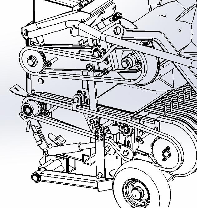
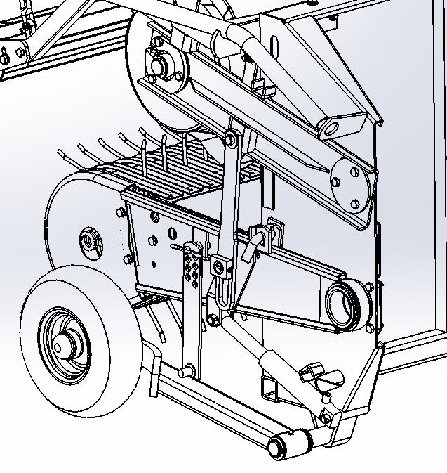
11 THE MOST IMPORTANT COMPONENTS 1 = Collection drums (corn) 2 = Front guide nozzles (corn) 3 = Spindles for collecting fallen corn (corn) 4 = Upper guide (corn) 5 = Hydraulic cylinder for regulating the height of the cut (corn) 6 = Stoppers for regulating the height of the cut (corn) 7 = Coupling to the tractor 8 = Lateral hydraulic displacement 9 = Transmission box 10 = Control box for the machine functions 11 = Regulators (stoppers) of the pipe descent 12 = Protection of the front nozzles 13 = Blades disc lid 14 = System for sharpening the blades 15 = System for rotating the pipe 16 = Hydraulic block 17 = Pipe articulation cylinder 18 = Ejector pipe 19 = Flap regulating cylinder 20 = Pipe extension W=1.00 m. 20A= Pipe extension W=1.40 m. (option) 20B= Pipe extension W=1.80 m. (option) 21 = Discharge nozzle 22 = Pipe articulation with vertical extension of 0.21 m. 22A= Pipe articulation with vertical extension of 0.76 m. (option) 23 = Collecting and milling unit 24 = Hydraulic hoses for connecting to the tractor 25 = P.T.O. cardan 1 3/8 -Z=6/Z=21/Z=8x32x38 26 = Control box for the metal detector (option) 27 = Blades disc 28 = Lower intake rollers 29 = Upper intake rollers 30 = Corn chopping system (corn) 31 = Collection drum (grass) 32 = Deflector (grass) 33 = Security tube (grass) 34 = Auger (grass) 35 = Support wheel (grass) 36 = Closing device (grass) 10

12 20B
13 Technical information (Subject to modification for the purposes of technical development) Power requirements: 3-line head for corn: P.T.O. rotation Diameter of the blades disc Opening for forage Number of blades Permanent level of sound emission Weights: Mex5 machine with discharge pipe Accessories: 3-line head for corn: Pickup 1.90 m of 110 KW (150 HP) 1000 rpm 1220 mm 800 cm max db(a) approx kg approx. 850 kg Approx. 510 kg Dimensions: Mex5 machine for corn or grass Length Width Height with extension of 0.21 m at work Height with extension of 0.76 m at work Height with extension of 0.21 m at transport Height with extension of 0.76 m at transport 2.80 m (corn)-2.40 m (grass) 2.20 m (corn)-2.25 m (grass) 4.25 m 4.75 m 2.72 m 3.22 m Necessary plugs 1 double-effect hydraulic plug min. pressure.: 140 bar max. pressure.: 180 bar 1 plug with 3 pins (12 volt) (see appendix) Tyres Application Máx. Pressure (bar) 13x Grass pickup L.I. (Kg) S.I. Km/h (200 kg) A6 (30 km/h) Optional equipment: - Horizontal extension of the pipe (1.0/1.40/1.80 m) - Vertical extension of the pipe (0.21/0.76 m) - Metal detector - Transmission cardan in accordance with the P.T.O. of the tractor - Load sensing system All of the information is subject to revision. 12

14 FIRST CONNECTION TO THE TRACTOR HYDRAULIC CONNECTION VERY IMPORTANT: Before making the hydraulic connection to the tractor, check the oil condition. If it is contaminated, change it, otherwise the hydraulic block and remaining hydraulic components of your machine could be damaged. The machine needs 1 double hydraulic circuit, to activate the hydraulic block, in order to do this: - Connect the pressure line (1) and the oil return tube (2) (the tube with the bigger diameter is the oil return tube), the command lever of the line on the tractor has to be positioned so that the hose of the greatest diameter is making the return to the tank. Note: If the oil heats up during functioning, and the tractor only has a constant flow rate pump, then it should be linked to a simple effect line (see image). - Connect the pressure hose (1) to the single action control unit. Connect the oil return hose (2) (with the bigger diameter) to a direct connection to the oil deposit. If the tractor allows it, reduce the oil flow rate REGULATION OF THE HYDRAULIC BLOCK: Pos. "H±10 mm" to closed hydraulic system Tractor with variable flow rate pump Before making the connection, the LS screw on the hydraulic block should be adjusted to the quota of ±10 mm (totally fasten LS) Pos. "H±17 mm" to open hydraulic system Tractor with constant flow rate pump The position of the LS screw on the hydraulic block should be adjusted to a quota of ± 17 mm. (totally unfasten LS)- (factory configuration). Warning! If this is not done, the overload valve on the hydraulic system of the tractor is continuously in use and an excessive heating of the oil will take place. If the tractor has a closed hydraulic system and the hydraulic block is in the position "A=17" then the hydraulic oil will heat up (especially due to the constant pumping of the maximum quantity of oil). LS A Solution: Place the tuner LS on pos. A=10 mm LS = Load detection 13

15 FIRST CONNECTION TO THE TRACTOR Connection of the hydraulic hoses, for tractors with fixed flow rate pump. - Disconnect the P.T.O. before making the connection - Place the lever (ST) of the control unit in the fluctuating position (neutral position), - Ensure that the rapid valves are clean. - Make the hydraulic connection of the hydraulic block. A double effect - Check if the hose of the smaller diameter is the one with pressure. Connection of the hydraulic hoses, for tractors with variable flow rate pump. - Disconnect the P.T.O. before making the connection - Connect the return hose (larger diameter-3/4 ) to valve (R), the pressure hose (1/2 ) to valve (P) and, finally, the smaller diameter hose (1/4 ) to valve (LS). Power source Necessary connections to the tractor 3-prong current plug - Connect the attached 3-prong plug to the rear of the tractor - Power source through a relay (9) The relay is connected to the ignition switch (10). - The diameter of the conductor is at least 4 mm 2 - Fuse 16A (11) You may find a complete diagram of the electrical connections on the list of spare parts. Ls P R This connection may only be made by a specialist Do not connect directly to the ignition switch - There is a risk of fire or damage to the electrical unit. Use only fuses at the recommended power as the use of stronger fuses will destroy the electrical unit! 14

 place with good visibility.")

 Explanation of the command functions A = This button has")
 B1/C1 (red) = Executes function 1 for orientation of the discharge")

16 Establish the connection with the tractor - After concluding the work as demonstrated, connect the three-pin jack to the tractor power socket. - Check if the lights on the command panel (13) are working - Install the command (magnetic base) in the interior of the tractor in an accessible (metallic) place with good visibility. 13 INITIAL CONNECTION TO THE TRACTOR - Switch the lever (ST) to the "ON" position and affix it. Check if the hose of the smaller diameter is the one with pressure, otherwise reverse the connection of the hoses or reverse the position of the ST lever, affixing it again. - The system is protected with a 15A fuse on the power jack of the command (5) Explanation of the command functions A = This button has two functions: When it is continuously pressed, it switches on and off the command, when it is pressed with one simple touch it commutes the functions in accordance with the colour of the bulb (green or red) B1/C1 (red) = Executes function 1 for orientation of the discharge nozzle D1/E1 (red) = Executes function 2 for the rotation of the discharge pipe F/G (red)= Executes function 3 of coming closer/ /moving away from the ground of the corn/grass. H (red) = Executes function 5 which reverses the rotation of the head and the feed rollers, whereby you just need to press the button. When you stop pressing, the direction of rotation returns to the initial one. B2/C2 (green) = Executes function 6 for lateral displacement of the machine (offset) D2/E2 (green) = Executes function 4 for the articulation of the discharge pipe 5 1 B1 B2 C1 C2 D1 D2 E1 E2 F1 G1 H1 Command indicator lamp Green/red 4 6 B
17 Coupling the machine to the tractor - Before coupling the machine, check whether the tractor has counterweights at the front or at the back (in accordance with the machine application at the back or at the front, respectively), required to balance the weight of the machine (2150 Kg). - Couple the machine to the 3 points of the tractor, so that it is parallel to the ground; in order to do this, adjust the bar (1) and, if necessary, the coupling (2) - The W 2600 transmission cardan of the machine must not be shortened, since the sliding surfaces are hardened. Therefore, the distance between the tractor's PTO end and the machine's PTO should be approximately 800 mm (min.); if the arms of the tractor do not allow it, you will have to use an extension (3) (option) and choose the required distance, which can be of 125, 160 or 195. Check that there is no interference of the sliding zones by lowering and raising the machine; should it occur, it could damage the transmission box of the machine Attention! - The admissible angle (35º) of the transmission cardan should not be exceeded, when raising the machine to carry out manoeuvres, disconnect the PTO of the tractor. - The minimum quota of overlapping of the transmission cardan sliding zones should be 150 mm (see chapter on the P.T.O. transmission cardan). - Couple the machine to the tractor only when all of the safety shields are in place. - When you couple trailers or accessories to the tractor you should take special care! There is a risk of injury by crushing and cutting points in the area of coupling at 3 points of the tractor! 16
18 Lateral adjustment of the machine in relation to the tractor. The machine may work centrally aligned with the tractor or displaced about 300 mm to the right (if the width of the tractor is over 2.3 m); for each of the positions, the front transmission box will have to be positioned differently, so that the cardan angle does not exceed what is recommended. The position change is carried out by the hydraulic cylinder (5), activated in the command. - Hang the machine on the tractor arms - Remove the latch (3) - Activate the cylinder (5) - The tubular stay (2) holding the machine, slides in the support cat. II or III. - Replace the latch (3) in the new position. - Replace the strut (4) of point 3, so that it is centred with the machine Centred position 960 RPM on blades disc-corn 520 RPM on blades disc-grass To sharpen the blades Reverses the direction of rotation Off-centred position 960 RPM on blades disc To sharpen the blades Reverses the direction of rotation Z=62 Z=49 Minimum Z=49 Z=47 Z=62 Z=47 Connection to the tractor (1000 RPM)-corn Connection to the tractor (540 RPM)-grass 5 Maximum 5 Positioning of the transmission box to the centred position, with the machine installed at the back of the tractor.[from 150 CV (corn)] Positioning of the transmission box to the off-centred position, with the machine installed at the back of the tractor. [From 150 CV (corn)] 17
19 760 RPM on blades disc 760 RPM on blades disc Z=62 To sharpen the blades Reverses the direction of rotation Z=49 Z=62 Z=47 To sharpen the blades Reverses the direction of rotation Z=49 Z=47 Connection to the tractor (1000) RPM Positioning of the transmission box to the centred position, with the machine installed at the back of the tractor. (Up to 145 CV) Positioning of the transmission box to the off-centred position, with the machine installed at the back of the tractor. (Up to 145 CV) 790 RPM on blades disc To sharpen the blades Reverses the direction of rotation 790 RPM on blades disc To sharpen the blades Reverses the direction of rotation Z=47 Z=62 Z=47 Z=62 Z=49 Connection to the tractor (1000) RPM Z=49 Positioning of the transmission box to the centred position, with the machine installed at the front of the tractor. (1000 RPM on PTO) Positioning of the transmission box to the off-centred position, with the machine installed at the front of the tractor. (1000 RPM on PTO) 638 RPM on blades disc 638 RPM on blades disc Z=49 Z=49 Z=62 Z=47 Z=47 Z=62 To sharpen the blades Reverses the direction of rotation Positioning of the transmission box to the centred position, with the machine installed at the front of the tractor. (540 RPM on PTO) To sharpen the blades Reverses the direction of rotation Connection to the tractor (540) RPM Positioning of the transmission box to the off-centred position, with the machine installed at the front of the tractor. (540 RPM on PTO) 18
20 Changing position of the transmission box To change position of transmission box, from position I to position III or vice-versa: - Remove the nuts (42) and the rings (41) - Remove the cardan protection (40) - Remove the screw (46), the ring (45) and the piece (44) - Remove the shaft (43) - Change the box position to Pos. I (Z=49) or Pos. III (Z=62) - Install pieces 27, 30, 31, 32, 33 as illustrated - Install the shaft (43) in the new position - Install pieces 44, 45, 46 - Install the cardan protection (40) - To apply the strut (34) in the new position, see previous page. Pos. I (Z=49) Pos. III (Z=62) 19
21 Metal detector (FKS) - option Equipment to be assembled on the tractor: - Install the control box of the metal detector, and the control box inside the tractor in a safe place and within the driver's reach. - Connect the electrical power cable to the two boxes and to the respective jack of the tractor. - Switch on the green button, the light goes on, if this does not happen, check the connections of the cables. Explanation of the functioning of the metal detector: On the control box of the metal detector, there is a green button/light, to switch on/off the metal detector and a red button/light to cancel. There is also a warning horn. 1- When you press the green button, the respective light goes on and the detection system is active. 2- Then press the red button, to redefine the metal detector (stand by), and the red light will go off. 3- During the work, whenever the system detects any foreign metal object at the entrance to the feed rollers, the red light will go on, the horn is switched on and immediately the rollers are blocked, then they reverse their direction of rotation. 4- After checking that the metallic object has been totally removed, press the red button and the feed rollers will once again take up the normal direction of work. - If the red light and the horn are in permanent warning, check the electrical cable ref Control box of the metal detector Control box Electrical power cable (Ref Electrical cable ref (±13.00 m) 12 Volts Green Horn Red button/light Rollers blocker Electrical cable ref (±7.80 m) Metal detector Hydraulic roller reverser 20
22 Maintenance note: When you undertake any soldering work on the machine equipped with a metal detector, there is a risk of magnetisation. If the metal detector is not working correctly, it will have to be demagnetised; in order to obtain help, contact our aftersales service. 21
 at the steering wheel.")
23 Tuning of the work speed Recommended rotation of the blades disc and respective transmission gears to the feed rollers: Corn Grass 760/790/960 RPM 520/638/(760*) / (790*) RPM Z=19 Z=19 Z=23 Z=15 Z=19* Adjusting the length of the cut Using alternative pulleys and number of blades (H) at the steering wheel. Tractor F = pulley for corn G = pulley for grass H = number of blades at the steering wheel (10/5) 22
, use the hydraulic inversion switch (D) (V belt loosened).")
24 F theoretical cutting length G theoretical cutting length Avoid, if possible Avoid, if possible Alteration of speed of the feed rollers Move the V belt. The speed of the feed roller is altered by repositioning the V belt on the three alternative pulleys. To move the V belt (E), use the hydraulic inversion switch (D) (V belt loosened). Assembly or removal of the blades Number of blades The blades may be assembled or removed at any time without the need to readjust them when they are replaced. It is only necessary to ensure that there is no imbalance at the steering wheel (only 10 or 5 blades should be installed). 23
 when you remove the blades Replace the blades in the same place.")
25 Attention! When you remove the blades, only loosen the cutter retention nut (1). Do not touch the adjustment nuts (2) when you remove the blades Replace the blades in the same place. - After the first 10 hours of operation, check the tightness of the hexagonal nuts (1) and the gap between the blades and the counterblade (S=0-0,5 mm) 24
26 25

 is completely closed (clockwise), B D1")
27 Transport by road Important! - When driving with the MEX 5, do not exceed the maximum permitted speed (25 km/h) and adapt the speed to the conditions of the road. - Pay attention to the total height of the discharge pipe. Max m Transport position How to fold down the pipe: - Make the hydraulic connection of the machine hydraulic block to the tractor, as described above (initial connection to the tractor), - Turn the pipe to the front in the direction of the tractor using the D1 and E1 functions of the command, - Check whether the hydraulic regulator (B) is completely closed (clockwise), B D1 D2 E1 E2 Regulator positioning in the machine with vertical extension of 0.20 m Regulator positioning in the machine with vertical extension of 0.70 m 26
 as indicated in the picture D C E E - With the (D2) function of the command, lower the pipe, control the")


28 - With your left hand, pull the unlocker (C) and simultaneously pull the lever (D). - Then place the element (E) as indicated in the picture D C E E - With the (D2) function of the command, lower the pipe, control the descent by opening the regulator as much as necessary (B) - Leave a gap between the pipe ant the tractor cabin, so that it does not damage the latter. The maximum height to ground allowed in public routes is 4.00 m. - Close the regulator (B) - Adjust the safety struts (G) with nuts (H), so that they support the pipe weight. - Take special care when driving in bridges or near electric cables. - If you choose to fold down the pipe over the machine (back of the tractor), do not forget to properly signal the end of the pipe, in accordance with the traffic rules in force. H G Danger signal 27


 as shown in the picture, retighten nut (1) (this")
 function of the command, place the safety levers (1) in the")
29 Attention Before initiating the transportation, place the safety devices on the corn cutting head or on the grass pickup. - For the corn cutting head: - Protection of the front nozzles Model with lateral spindles Model without lateral spindles Placing the protection for transportation Completely loosen nut (1), position hook (2) as shown in the picture, retighten nut (1) (this procedure should be carried out in both sides) Raise the cutting head to the (F) function of the command, place the safety levers (1) in the position indicated by the arrow. 1 F 1 28
.")


30 - For grass pickup: Raise the grass pickup at the (F) function of the command, and place the safety pins (23). Place the grass pickup's right wheel in transport position; to do so: 23 - Remove the perforated support in the location indicated by the arrow; loosen screw (1) with an open end wrench 22 or a metal rod Ø 12 max., so that the latch can be rotated below (2) Rotate the wheel support horizontally as shown in the picture, - Then, rotate vertically and place the support (3) as shown in the picture. 3 29
. Your foot can easily slip from the pedal.")


31 Operating in a field Working recommendations - Before commencing each work session, check whether all of the screws and pins are tightened and whether the drive shaft was correctly assembled and stuck between the machine and the tractor. - Switch off the tractor motor before working on the machine (do not leave it simply disengaged). Your foot can easily slip from the pedal. "Wait for a complete stop". - Adjust the working speed in accordance with the working conditions. - During the operation of the machine, the permitted P.T.O. rotation (1000 rpm) may not be exceeded. - When you remove blockages, never place yourself in the danger zone at the power entrance to the accessories! Remove blockages by simply reversing the power or with the motor and the P.T.O. switched off! A - Manual charging is not permitted! - Control the beginning of the movement of the machine slowly with the tractor clutch to avoid damage. - Avoid placing yourself in the exhaust zone of the machine! - Comply with the safety distance from overhead electrical cables! C Regulation of the upper flap movement (A) The movements of the flap may be regulated according to the user preferences; in order to do this, use regulator (B). After carrying out the regulation, do not forget to block the regulator in pin (C) B B Flap regulator positioning in the machine with vertical extension of 0.70 m Flap regulator positioning in the machine with vertical extension of 0.20 m 30
32 31
 23 - Slowly put the machine into motion, then increase the P.T.O. rotation to 1000 min-1 (rpm).")
33 Operating in a field 2 - Remove the protection from the front nozzles in the corn accessory (1), remove the safety levers (2) in the direction of the arrow On the grass pickup, remove the safety pin (23) 23 - Slowly put the machine into motion, then increase the P.T.O. rotation to 1000 min-1 (rpm). This rotation should be maintained as constant as possible in order to guarantee a consistent and complication-free operation. The moving speed depends on the following factors: - Performance of the tractor - Quantity of forage to be cut - Conditions of the terrain - Method of harvesting (trailer behind the machine or parallel to the machine) - When you make turns with the trailer installed at the back, pay attention to the distance between the machines. 32
34 Corn cutting head for 4 rows The corn cutting head is ready to operate with 4 rows. This feature should be used to cut the path openings (beginning of the harvest) whenever the tractors are wider than 2.20 m. - The useful inner width will be 2.35 m. - The outer width will be 2.70 m. (Do not travel on public routes while the machine is in this position). In order to prepare the machine for 4 rows, proceed as follows: - With key (1), slightly loosen screw (2); then, using the same key, turn strut (3) counter-clockwise, until the required opening is achieved Retighten screw (2) 33

35 - Using the same key (1) turn strut (4) clockwise, to adjust the guide to the new work length. 4 - After carrying out all the adjustments as described above, the positioning achieved must be as shown in the picture below. In order to achieve better results in cutting the rows nearer the edge of the machine, element (5) should be adjusted in the direction indicated by the arrow, as much as possible. Note: In order to operate with the machine in this position, an increase in available power will be required m 2.70 m Positioning for 4 rows cutting 34
36 Warning: Be particularly careful while manoeuvring the machine in this position (4 rows), since the machine will be wider than the tractor. To return the machine to the 3 rows position, proceed in the reverse order, as described above m 2.25 m Positioning for 3 rows cutting 35
37 Pipe blockage Switch off the motor and remove the key. - Wait until the machine has completely stopped. - Remove the shields (R, R1). - Remove the blockage. - Reinstall the shields (R, R1). Blockages, foreign objects and blowing power In the case of a blockage or if a foreign object is collected, you should use the reversing system. - Reverse the power mechanism, using the push button (C). C Attention! Do not take up again the original power direction (stop pressing the button (C)), without ensuring that the entrance to the machine is unblocked or the foreign object has been removed - The blowing power may be adjusted by means of the number of shovels installed at the wheel: 5 or 10 shovels uniformly distributed. 36
 1 - Put the safety pin in place (23)-(Grass) - When you leave the tractor, always lower the accessories to the ground.")


38 - How to switch off the machine General notes - Place the safety lever (1) in the position indicated by the arrow. (Corn) 1 - Put the safety pin in place (23)-(Grass) - When you leave the tractor, always lower the accessories to the ground. - When you switch off the machine, protect it so that it does not move or fall. - As a principle, make sure that the machine is well protected against bad weather. - Move the hydraulic support (2) downwards and affix it in the correct position. - Lower the machine until it is fully supported on the ground. - Disconnect the hydraulic hoses and the electric cable; uncouple the P.T.O. transmission cardan. - Attach the magnetic control box (3) to the machine, or disconnect the jack (4) and keep the command in a safe place. - Uncouple the machine from the 3 points of the tractor Cleaning - In order to obtain more details, see the Maintenance chapter "Repairs". Due to the material residues, the machine should be carefully cleaned at the end of the season. 3 4 Ensure that you comply with the instructions for lubrication and maintenance (see the chapter on "Maintenance Care"). 37
. Attention!")

 - Remove the piece (3) - Remove the shield (14) - Apply the piece (3) at the place indicated - Affix")

39 Assembly of the corn cutting head Note: The disassembly is undertaken in the reverse order. The assembly or removal of the corn accessory should be undertaken on a flat surface (or compensated with supports). Attention! Safety advice There is risk of injury if the P.T.O. is started up accidentally. Therefore it is absolutely necessary to remove the drive shaft before beginning this work Support the corn head on four points in order that it is approximately 300 mm from the ground, - Place the bolts (1) in the indicated position - Remove the bolts (2) - Remove the piece (3) - Remove the shield (14) - Apply the piece (3) at the place indicated - Affix the screws (4) at the place indicated Bring the machine closer to the head as indicated by the arrow (A) Attention: This manoeuvre must be done with the help of another person, to indicate to you the correct alignment (see fig.) for coupling the machines, thereby avoiding damage. A - In order to guarantee the vertical alignment between the tube (5) and the piece (6), use the hydraulic train of the tractor to raise or lower the machine as necessary. A
40 - Place the lower bolts (B) in the position indicated in the picture. B 4 - Connect the hose (3) to the rapid valve (4) of the hydraulic block, make the hydraulic connection of the machine to the tractor, with the command of the machine, open or close the cylinder (1) until you manage to apply the bolt (2). Then, apply the bolts (5). In order to bring the struts (6) closer to the hole, just loosen the nuts (7) sufficiently, place the safety lever (8) down and fit in the pin (9) Apply the transmission cardan (10) as indicated in the picture, push the shaft (11) in the direction of the arrow (C) and, at the same time, press the safety pin of the cardan (E) until the notch (D) covers the pin. 10 E D 11 C 39
 completely and lock them.")
41 Assembly of the grass pickup in the machine Assembly of the pickup accessory in the machine. Safety advice There is risk of injury if the P.T.O. is started up accidentally. Therefore it is absolutely necessary to remove the drive shaft before beginning this work. - Pull out the supports (26) completely and lock them. The pickup drum should be affixed with bolts (23) onto the central hole of the frame. Attention! Do not use the hydraulic elevator when the collector accessory is stuck (23)! 40
 is attached to the pickup.")


42 - With Mex5 installed in the tractor arms, and using the 3rd point (preferably hydraulic), tilt the machine as much as possible, carefully approach Mex5 to the pickup and, with the arms, position the machine so that rod (1) is attached to the pickup. - Lift the machine using the tractor arms, so that the pickup is suspended and against the Mex machine, rod (2) will be correctly positioned; regulate the 3rd point in order to keep the machine as horizontal as possible. - Move the supports (3) upward and secure them; this way, the pickup will be safely attached. - Connect the hydraulic valve to the Mex5 block. 1 3rd Open protection (34) - Insert the shaft (33) in the transmission cardan and secure it. After the successful assembly of the pickup accessory, the bolts (23) should be removed once again. 41
 is undertaken with tuners A, B and C in order to guarantee the")
 falls and divides the corn before it is cut, then you need to move element (1) in the direction (A) and once again tune the movement (C) so that")
43 Adjusting and tuning the corn head - The upper guide may be regulated on the horizontal and on the vertical (see picture) in accordance with the height of the corn to be cut. C - The lateral guides may be tuned in accordance with the conditions of the corn and the height of the cut - Tuning of element (1) is undertaken with tuners A, B and C in order to guarantee the quotas mentioned in the picture, and that it does not interfere with elements (2), this positioning applies to most situations. When the corn is of small dimensions, and element (1) falls and divides the corn before it is cut, then you need to move element (1) in the direction (A) and once again tune the movement (C) so that it does not interfere with element (2). Very important: Check that element (1) does not interfere with element (2) (manually rotate the collection drum), because if that happens, it will damage the machine during the start-up. 80 A B Due to the existence of stones and other obstacles on the terrain that could damage the lower zone of the machine, you should not do cuts lower than 135 mm

44 Maintenance, Repairs General maintenance advice In order to keep the accessory in good conditions even after a long service life, please respect the following advice. Safety points: - Switch off the motor if you need to do adjustments, maintenance or repairs. - Do not work underneath the machine without a secure support. - Tighten the screws again after the first hours of operation. Spare parts a. The original components and accessories were designed specifically for these machines and applications. b. We would like to be clear that components and accessories that have not been supplied by us have not been tested. c. The installation and/or use of such products may, therefore, alter or negatively influence the construction characteristics of the device. We are not responsible for damages caused by the use of components and accessories that have not been supplied by us. d. Alterations and the use of auxiliary pieces that are not permitted by the manufacturer shall invalidate any responsibility. 43


45 Maintenance, Repairs Drive shafts - Lubricate the drive shafts every 8 hours of functioning. - Disassemble the sliding sections and lubricate them well. Cleaning the machine parts Attention! Do not use high pressure cleaners to clean the rolling or hydraulic pieces. - Risk of the appearance of rust! - After cleaning, lubricate the machine in accordance with the lubrication scheme and do a short test. - Cleaning at too high a pressure could cause damages to the varnish. Winter Storage - Carefully clean the machine before storage. Install protection against bad weather. Protect the pieces that are exposed to oxidisation. Lubricate all the lubrication points in accordance with the lubrication table. Hydraulic unit Careful! Danger of injuries or infection! 44

 is worn off due to sharpening, then new blades need to be installed.")
 in the direction of the arrow.")
46 Sharpening the blades General The correct adjustment, together with the correct sharpening of the blades guarantees that the forage is cut with precision, and saves energy. The integrated sharpening device allows uniform sharpening of all of the 10/5 blades in an operation. Safety tips - Before sharpening, check the adjustment of the sharpening disc and the condition of the blades. - Check the wear of the sharpening disc. A gap of at least 1 mm from the plate to the edge. -When the coated area (5) is worn off due to sharpening, then new blades need to be installed. Before sharpening remove the movement from the corn/pickup head; in order to do this: B -Hydraulically activate the reverser on the button (D) of the command. - Continuing to press the button, move the element (A) in the direction of the arrow. - Stop pressing button (D), the pulleys shall be at a distance of around 3 mm, enough for the pulley (C) not to have movement. If this does not happen, regulate the distance between pulleys on the tuner (B). Note: In order to have movement on the head/pickup, you shall have to place element (A) in the initial position. A 3. Another possibility to remove movement from the corn cutting head and sharpen the blades in safety is the following: - Remove the shaft (11) in the direction of the arrow (C), pressing the locker (E) of the cardan (10) C D 10 E 11 Always use eye protection when undertaking the tuning. C Fault correction When the exterior (Z) of the blade is worn away more than the interior: - Check if the sharpening disc is correctly placed 45

 as can be seen above. 6. Adjust with the adjustment screws (2). 7.")
47 Adjusting the sharpening disc to the blades and vice-versa Safety advice There is risk of injury if the P.T.O. is started up accidentally. Therefore it is absolutely necessary to remove the drive shaft before beginning this work. 1. Place the machine in the working position and raise the pickup/head for corn. 2. Switch off the tractor motor. 3. Open the box shielding of the blades disc box and secure it with the hook (20). 4. Adjust the blade exactly parallel (0-0.5 mm) to the corresponding cutter. 5. Rotate this adjusted blade as far as the abrasive disc and adjust the disc so that it is exactly parallel (C - C) as can be seen above. 6. Adjust with the adjustment screws (2). 7. Rotate the blade until it is positioned vertically. 8. Adjust the disc vertically with screws (2) so that the blade touches the upper part of the disc (D 0 mm), with a distance of (E 1.5 to 2.0 mm) in the lower part. 46
 The sharpening or adjustment should be undertaken when the head/pickup is raised.")
 to the position in order that the sharpening can take place along the whole length of the blade (indicated by a shower of sparks or")
48 Sharpening procedure For your safety When you use the sharpening equipment, position yourself behind the machine. Disconnect the movement of the corn head/pickup (see the chapter on safety tips "Sharpening of blades") The sharpening or adjustment should be undertaken when the head/pickup is raised. Sharpen at half the rotation of the P.T.O (rpm). - Open the protective lid (1). - Move the sharpening disc by means of the adjustment nut (M) to the position in order that the sharpening can take place along the whole length of the blade (indicated by a shower of sparks or examining the blade after a short period of sharpening). The sharpening disc should not rotate faster (n2) than the blades disc (n). - The sharpening disc should rotate at approximately rpm in the same direction as the blades disc, if it is in the correct position and at the correct adjustment of the pressure of the sharpening disc. If this is not the case, the pressure of the sharpening disc on the blades should be altered accordingly or its position should be checked. - Sharpen the blade along the whole length (normally 2-5 minutes). If the shower of sparks becomes weaker with the passage of time and the pressure of the sharpening disc weakens, this is because of dirt on the disc; move it away for some time and restart the operation again. The sharpening disc will clean itself, this operation is very important, because it is the only way to get perfect contact between the blade and the disc. - Retrieve the disc as soon as the sharpening process is completed, fold it down and unplug the power plug. - Raise the lid of the blades disc - Check the edge Safety advice There is risk of injury if the P.T.O. is started up accidentally. Therefore it is absolutely necessary to remove the drive shaft before beginning this check. 47
. Check the space between the blades and the cutting mouth. - The gap should be 0-0.")
, check the gap (around 0.5 mm).")
49 Adjusting the blades disc Safety advice There is risk of injury if the P.T.O. is started up accidentally. Therefore it is absolutely necessary to remove the drive shaft before beginning this work. Open the lid - Affix it to the tower with the hook (20). Check the space between the blades and the cutting mouth. - The gap should be mm, if this does not happen: After pulling backwards and rotating the safety pin (22) of the adjustment nut (21), the latter should be blocked with the attached key (23). By rotating the blades disc in the opposite direction to the cut, the blade moves up against the counter-blade (24), check the gap (around 0.5 mm). Then, affix the adjustment nut (21) with the safety pin (22), remove the key (23) and keep it. Finally, rotate the blades disc a few times by hand. Attention! For the integrated grain crusher, check the lateral gap of the crushers. - The individual readjustment of each blade is only necessary if the range of the sharpening ring (25) has already been exhausted due to frequent adjustments in the cutting wheel (the sharpening rings are seated one against the other). Attention! It is absolutely necessary to insert the closing bar (23) correctly and to remove it in accordance with the adjustment pressure. Replacing the blades Remove the worn out blades Then pull and rotate the safety pin (22), affix the adjustment nut (21) with the key (23) and rotate the blades disc 3 1/2 times (= 7 mm of adjustment) in the direction of the cutting. Then, affix the adjustment nut (21) with the safety pin (22), remove the key (23) and keep it. Screw on each blade securely and adjust each side edge of the cutting with the counter-blade, (0.5 mm) using the adjustment nuts (B). Finally, rotate the blades disc a few times by hand. 48
50 Repairs of the basic equipment. When loosening the 3 hexagonal screws (6), the group of intake rollers may be folded from position (Y) to position (Z), thereby facilitating the repairs of the intake rollers and the counter-blade (35) Reversal or replacement of the counter-blade After loosening the four hexagonal screws of the counter-blade, this may be reversed or replaced. - You should reverse the counter-blade after 150 ha of work and after another 150 ha of work you should replace it. Reversing or replacing the counter/blade in time saves energy and improves the quality of the cut. In the case of the replacement of the counter-blade, the blades must be readjusted. The abrasive disc readjusted. Corn chopper set: 49
.")
 only slightly.")
 slightly.")
 between the ventilator and the blade should be 5 mm max.")
 between plates II and the ventilator should be adjusted to about 3 mm by means of the adjustment nut (J).")
 with the start-up torque of M=165 Nm.")
, the better the ventilation, and, consequently, the higher the projection capacity - Rotate the")
51 Installation of the Corn Chopper Kit Push plate II, allowing the clamp spring (1) to attach to plate (2). Open the top lid and remove the ventilator (3a). Assemble an adjustable ventilator (13) using - Two covering plaques (14) - Two hexagonal screws M14x50 - Locking nuts M14. Tighten nuts (5) only slightly. Insert the grooved screw (10) by means of the covering plaque (16); - Insert the hexagonal screw (18) in the blades disc and tighten screw (10) slightly. Rotate the blades disc by hand until the regulator stops at plate II, at the exact position of the gaps (X, Y and Z). - The axial gap (X) between the ventilator and the blade should be 5 mm max. (The reference measure (Z) should be at least 5 mm.) - If the adjustment gap (Z) is under (5 mm) readjust the ventilators. The radial gap (Y) between plates II and the ventilator should be adjusted to about 3 mm by means of the adjustment nut (J). - After tightening the adjustment nut (J), tighten the safety nuts (5). The grain ventilator may not be radially shaken! - Tighten the nut (5) with the start-up torque of M=165 Nm. - Tighten the hexagonal nut (19) - Finally, tighten the hexagonal nut (17) with the start-up torque of M=120 Nm. Attention! The smaller the gap (Y), the better the ventilation, and, consequently, the higher the projection capacity - Rotate the blades disc again and check that there is no interference. - Adjust regulator screws A placing them against the already regulated ventilator. - Adjust gap Y using nut J, placing the ventilators against the regulator screws A. - Gaps X and Z are regulated as described above Tighten the remaining nuts with the torques described above. - Move screws A so that they do not interfere with the ventilators. A 50
 between the blades and the cutting wheel, using a hexagonal screw M1 4X25 (11) and spring ring. Attention!")
52 - Insert the crushing plaque I (8), rotate it backwards and secure it to both of the blocks (3). - Insert the blocks with a hammer and affix them with cotter pins (4). - Assemble the protective piece (9) between the blades and the cutting wheel, using a hexagonal screw M1 4X25 (11) and spring ring. Attention! Rotate the blades disc to check for any interference -Close the blades disc box. Pay special attention! All of the nuts of the grain crusher, as well as the protective pieces (9), should be tightened securely every 10 hours of work. The central readjustment of the blades disc makes the crushers come close laterally to the counter-blade over time. If the gap (X) goes down to 1 mm, it should be readjusted to 5 mm again. The reference measure (Z) should be at least 5 mm. 51


. If oil does not come out, add it.")
. If oil does not come out, add it. To change the oil, the box must be removed from the machine.")

53 4 Maintenance care to be taken into account. General information Accurate care and correct maintenance will ensure constant readiness and a long useful life for the machine; especially recommended is the use of a good lubricant and compliance with the lubrication instructions. To check or once again fill the transmission oil, the machine should be levelled. Attention! After each cleaning with a high-pressure machine Lubricate the machine in accordance with the lubrication scheme and do a short test. Lubrication instructions The transmission box to the group of rollers functions in a SAE 90 transmission oil bath, which should be replaced once per year. The quantity of oil is approximately 0.5 L. Periodically check the oil level. For this, with the machine on the horizontal, remove the screw (1). If oil does not come out, add it. The tractor/machine transmission box also operates in a SAE 90 oil bath, which should be changed after 100 hours of operation. Periodically check the oil level. For this, remove the screw cap (2). If oil does not come out, add it. To change the oil, the box must be removed from the machine. To check the oil level, the positioning of the cap (2) to the positions III (Z=62) and I (Z=49) has to be as indicated in the picture. The transmission system of the corn head comprises three gear boxes that are equally immersed in SAE 90 transmission oil which should be replaced once per year. The quantities are as follows: -Box (2) -1.5L-To check the minimum level, see figure (A) -The removal of the oil should be done by vacuum -Box (3) -2 L-To check the minimum level, see figure (B) -The removal of the oil is done through the orifice (D) -Box (4) -2 L-To check the minimum level, see figure (C) Add more if the level is not overlapping the display (E) -The removal of the oil is done through the orifice (F) 2 Figure A A E 30 to 35 mm mm F Figure C D 52 Figure B 3
54 Winter Storage The moving parts (group of rollers, blades disc, rotating collection drums, etc.), as well as the chains should be oiled to protect them from rusting. The machine should be stored well protected from harsh winter weather. Tuning the currents of the corn head: - After the first 10 hours of work, the transmission chains should be checked and adjusted if necessary 1 2 A C To tune the chains (1): - Remove the protective shields - Slightly loosen the nuts (3) - Do not forget to loosen the nuts that are to be found in the rear part of the bearing (6), in order to have access to these nuts, use the orifice indicated by arrow A. - Loosen the counter-nuts (4) - Adjust the chains with the elements (5) in order to obtain a quota (B) of approximately 5-7 mm B 53
55 Attention, the distance (C) between the axles has to be equal on both sides. - Tighten the counter-nuts again (3) and (4). - Check how the chain (2) is. If distance D is inferior to that indicated, you will have to remove one or more links or replace the chain (recommended option) 2 D=Min.35 mm Central roller chain: B Remove the shields (7) - Loosen the counter-nut (8) - Tighten the nut (9) until you get a quota (B) of 5-7 mm - Retighten the nut (8) - Replace the shields 8 - Protective clutch of the corn head: The corn head is equipped with a clutch (10), to protect the machine from possible objects that could cause damage and to soften the reversals that are 10 necessary. Its tuning is made in the factory. Nevertheless, when placing the machine in the 11 working rotation and when undertaking the reversal of rotation, if you notice a group of horizontal rollers of the shredder stopping and making an accentuated noise, this means that the general clutch of the shredder is acting before that of the head, which should not happen. In order to solve this, you will have to slightly loosen nut (11) so that 54
, because the reversals inflict wear on the clutch discs, which could result in the corn")
 in order to ensure the conditions described initially.")
56 whenever it does a reversal, the rollers of the shredder do not stop, with the head clutch acting first and softening the impact of the change in rotation. - The reversal of the rotation should only be used when it is strictly necessary (blockage of the feed mouth), because the reversals inflict wear on the clutch discs, which could result in the corn cutting and collection drums at work in more severe conditions stopping with the strain; then you will have to tighten the nut (11), if the problem persists then you will have to replace the clutch discs. If you replace the clutch discs, to tune the clutch again tighten nut (11) in order to ensure the conditions described initially. - Tuning the belts of the lateral spindles: If the lateral spindles stop during work, due to the effort caused by the fallen corn, adjust the chain tension in order to decrease distance L. To do so, tighten nut A in the direction shown by the arrow. (If distance L1 is already at its lowest, change the chain (type A 53 ¼ ). C 115 B L L1 A To check if the chain is correctly tensioned, proceed as follows: - Turn off the tractor (to avoid any accident) With both hands, as indicated in the figure, rotate the spindle towards the outside of the machine (opposite to the normal working direction), applying a force of approximately 250N (25 kg/f), so that the chain slides in pulley C, with no movement from the latter. If you are unable to rotate the spindle, remove tension from the chain by moving nut A in the direction opposite to the one indicated by the arrow. (Note: Each complete turn of nut A implies a tension change of about 80 N. (8 kg/f) After achieving the proper chain tension, adjust nut B, in order to ensure the indicated quota (115 mm) Take special care not to overtension the belt, otherwise, in case of a blockage caused by any foreign object, the belt or the cardan could be damaged. In case of blockage during work, stop as quickly as possible, otherwise the chain will be damaged due to its friction in pulley C. 55

57 Maintenance instructions for the grass collection accessory The only point of lubrication (4) of the collector accessory is on the left-hand side of the front plaque of the collection drum and should be lubricated with grease, every 20 hours of work. Attention! For technical reasons, this lubrication point should be oiled when the collector is in use. In order to avoid possible accidents, you should proceed with special care! The lubrication points of the transmission, of the collector should be lubricated frequently with grease. Air máx. pressure: 2,5 bar After each 6 hours of functioning Place grease 56

58 Stretching of the transmission chain of the auger roller: - Remove the roller protection - Loosen the hexagonal screw (2). - Adjust the chain - Tighten the hexagonal screw again - Replace the protection Stretching of the transmission chain of the pickup device: - Remove the pickup protection - Loosen the hexagonal screw (3) (at the front or at the back) - Adjust the chain - Tighten the hexagonal screw again - Replace the protection Adjust the feed roller: - Remove the pickup protection - Loosen the hexagonal nut (7) at the support of the wheel - Adjust the feed roller: - Tighten the hexagonal nut (7) again - Replace the protection Tuning of the transmission chain of the auger roller - Open the protection - Loosen the hexagonal screws (M). - Rotate backwards the counter-nuts (K) - Adjust the chain by rotating the hexagonal screws (S) Attention! Rotate both of the hexagonal screws (S) equally and in order, so that you avoid the shaft inclining, - Tighten the hexagonal screws (M) again. - Tighten the counter-nut (K) - Close the protection 57
59 Lubrication: Automatic Lubrication of the Chain Function: Whenever the corn head or the grass pickup is elevated hydraulically, the pistons of the oil pump (P) are activated. This action causes a small quantity of lubricant to be transported each time to the individual lubrication points. This pump has 7 outlets available, 3 for the shredder machine and 4 for the pickup/corn head. Therefore, whenever you couple the grass pickup or the corn head, remember to connect the corresponding tubes (A). Attention: Whenever you uncouple the grass pickup or the corn head, remember to disconnect the corresponding (A) tubes, otherwise they could be damaged. A Before use Check the oil level (OIL) in the recipient and fill it again if necessary. Please use only oil that is environmentally safe and biodegradable. 58

60 Location of the lubrication points of the Mex5. x1 x4 x1 x1 x1 x6 x2 x2 x4 B B 100 cst-eco Biodegradable CECL-33A-93 SAE 30 DIN NLGI 2 EP 59
61 x6 x2 x3 x2 x3 x2 X2 x1 B 100 cst-eco Biodegradable CECL-33A-93 SAE 30 DIN NLGI 2 EP x1 x1 A 13 Important note: Whenever you need to remove the corn cutting drums, do not forget to first take out element (A). 60

62 Lubrication points of the grass pickup 61
63 Breakdowns Before a breakdown may be repaired, disconnect the power plug and the tractor motor and wait for all of the moving parts to be immobilised. Never try to resolve a breakdown with the machine in use. - Switch off the motor and remove the key. General All machines will break down every now and then. The following information should help you to recognise the problems. You should always try to resolve the problem as soon as possible. Breakdown 1. Noise of the beat during use: 2. Overheating of the gear box: 3. Heating of a cap: Solution Adjust the tension of the chain. Check the level and the quantity of oil. Lubricate the machine in accordance with the lubrication plan. Admission 4. The clutch of the admission roles acts: 5. The clutch of the admission roles acts just a little: 6. The corn is not collected in a clean form: 7. The admission does not function at full speed: Blades disc 8. The stems of the corn are not cut in a clean form and at the desired height: Blockage or foreign substance at the mouth of the entrance Replace the clutch or the springs Examine the level of the cut and the elements of the cut Check the tension of the belt in V. Adjust the blades disc to the counter-blade or sharpen the blades. Ventilation 9. Very weak ventilation: 10. The ventilation tube blocks at start-up due to a fault in reaching the necessary rotation speed: Corn head 11. Blocked with foreign matter: 12. Blockage or blocking of the admission channel: The shovels are very worn, so replace them. Clean the blower tube. Put the machine functioning in reverse for a short space of time, wait for the moving parts to stop, remove the foreign matter. Check the functioning of the central roller 13. Pushes the corn forward without cutting it 14. Drums stop during work 15. The lower cutting discs stop and do not cut 16. The lateral spindles stopped Adjust the upper guide Check if the front nozzles are free of obstructions Adjust the clutch or replace the discs Replace the bearing rollers of the disc (piece no. 9 of set /9) Check the tensioner and adjust if necessary. 62

64 Grass pickup 17. Blockage with foreign matter 18 The teeth are bent or burying in the ground: 19 The pickup drum stopped: Put the machine functioning in reverse for a short period of time; when the moving parts come to a complete halt, remove the foreign matter. Adjust the feed roller height correctly The fuses (5) broke; replace with new ones, tighten them properly and install the protection. 63

65 Breakdowns and solutions for electrical faults When there is a fault in the electrical unit, the necessary hydraulic function may be performed by means of an emergency manual intervention. To activate Y4;Y5;Y6;Y7;Y8;Y9;Y10;Y11 Totally rotate clockwise To activate Y1;Y2;Y3, push the pin with the help of a sharp pointed object The attached scheme of functions presents the respective button that should be used for each necessary function. Be careful with the dangers involved in the raising and lowering and operations of activation or deactivation! 64
66 Hydraulic scheme of the functioning of the machine 5 65
 W2600-1 3/8 -Z=21 (option) Machine side Code Shaft Free wheel PTO 1 3/4 - Rotate right 20503071 Z=20 1 3/4 - Rotate right 20503090 Z=20 1 3/4 - Rotate right 20503089 Z=20 1 3/4 -")

.")
67 Transmission cardan PTO-options Application to the tractor Rear assembly Front assembly Tractor side Shaft PTO W /8 -Z=6 (standard) W /8 -Z=21 (option) W2600- Z=8x32x38 (option) W /8 -Z=6 (option) W /8 -Z=21 (option) Machine side Code Shaft Free wheel PTO 1 3/4 - Rotate right Z=20 1 3/4 - Rotate right Z=20 1 3/4 - Rotate right Z=20 1 3/4 - Rotate left Z=20 1 3/4 - Rotate left Z=20 Safety chain - Check if the protection tubes have chains to stop them from rotating. Check if the cardan has enough space to turn. Working instructions During the working of the machine, the rotation regime indicated on the cardan should not be surpassed. After switching off the tractor transmission, the machine will continue to move for some time due to inertia, so any intervention in the cardan should only be carried out after the machine has come to a complete stop. When parking the machine it is advisable for the cardan to be properly suspended by means of a chain (do not use the chains from the cardan protection tubes). 2) Articulation of the homocinetic joint Maximum angle at work and at rest 70º. 3) Articulation of the normal joint Maximum angle at rest 90º. Maximum angle at work 35º. Attention! Aim for the maximum possible overlapping of the tubes (min. 150 mm) Min. 150 mm 66
Directions for use VIBRO FLEX 7400
 Directions for use VIBRO FLEX 7400 Contents Introduction... 3 Identification... 3 Explanation of symbols... 4 Safety... 5 General safety advice... 5 Coupling and uncoupling... 5 Three-point hitch or linkage...
Wheel Horse. 44 Snowthrower. for 5xi Lawn and Garden Tractors. Model No & Up. Operator s Manual
 FORM NO. 8 Rev A Wheel Horse Snowthrower for 5xi Lawn and Garden Tractors Model No. 7966 890050 & Up Operator s Manual IMPORTANT: Read this manual, and your tractor manual, carefully. They contain information
AU DU PONT DE LUTTRE BRUSSELS BELGIUM PHONE: FAX: OPERATING MANUAL. Electric Fully Automatic Floor Saw FS 1218 EX
 AU DU PONT DE LUTTRE 74-1190 BRUSSELS BELGIUM PHONE: 322 34 83 162 FAX: 322 34 83 136 OPERATING MANUAL Electric Fully Automatic Floor Saw FS 1218 EX 2 Important information before you start! When the machine
Stone Burier Attachment. BCS Power Units
 Stone Burier Attachment Manufactured by R2 RINALDI S.r.l. to fit BCS Power Units Operating Instructions Before commissioning the machine, read operating instructions and observe warning and safety instructions.
INSTRUCTIONS AND SPARE PARTS READ CAREFULLY BEFORE OPERATING MACHINE
 SP Series OPERATING INSTRUCTIONS AND SPARE PARTS READ CAREFULLY BEFORE OPERATING MACHINE July 2006 Technical Data SERIES "SP Model SP 150 SP 250 SP 300 SP 400 SP 500 Capacity 149 li 198 li 250 li 302 li
Z Master. 62 Mower. for Z Master Z 255 Traction Unit. Model No & UP. Operator s Manual
 FORM NO. 9 88 Z Master 6 Mower for Z Master Z 55 Traction Unit Model No. 7408 89000 & UP Operator s Manual IMPORTANT: Read this manual carefully. It contains information about your safety and the safety
Operating and Maintenance Manual. for. HADEF overhead crane. as jointed crane TA
 5.52.714.00.1.0 Edition 03.2004 GB Operating and Maintenance Manual for HADEF overhead crane as jointed crane TA Subject to changes. 1 HADEF Table of Contents 1 General Page 3 2 Product description Page
HYDRAULIC PALLET TRUCKS
 HYDRAULIC PALLET TRUCKS HYDRAULIC PALLET TRUCKS MODEL Nos: PT550 GAL & PT685 GAL PART Nos: 7630234 & 7630236 OPERATION & MAINTENANCE INSTRUCTIONS 0204 Please read these instructions carefully before operating
Wheel Horse. 42 Mower. for Lawn and Garden Tractors. Model No & Up. Operator s Manual
 FORM NO. 9 559 Rev A Wheel Horse 4 Mower for Lawn and Garden Tractors Model No. 78 890000 & Up Operator s Manual IMPORTANT: Read this manual carefully. It contains information about your safety and the
JEEVES. JEEVES Installation Manual. Installation Manual The Easiest Do-It-Yourself Dumbwaiter on the Market
 1 888-323-8755 www.nwlifts.com JEEVES Installation Manual The Easiest Do-It-Yourself Dumbwaiter on the Market This manual will cover the installation procedure step-by-step. The installation of this dumbwaiter
Finishing Mower Estate 72
 Finishing Mower Estate 72 Owners/Operators Manual & Spare Parts List Issue Date: October 2011 1 Introduction Your FIELDMASTER Estate 72 Finishing Mower has been designed to do a range of work to your satisfaction.
Original Operating Manual
 matev GmbH Nürnberger Str. 50 90579 Langenzenn T +49 (0) 9101 9087-0 F +49 (0) 9101 9087-20 info@matev.eu www.matev.eu Original Operating Manual Front Power System und Front PTO shaft FPS- JD X 950 R for
HYDRAULIC PALLET TRUCK. MODEL No: PTE550 PART Nos OPERATION & MAINTENANCE INSTRUCTIONS
 HYDRAULIC PALLET TRUCK MODEL No: PTE550 PART Nos 7630171 OPERATION & MAINTENANCE INSTRUCTIONS 0604 Please read these instructions carefully before operating the truck Thank you for purchasing this CLARKE
FCT Precision Chop Forage Harvester. Directions for use. Original instructions
 FCT 1060 Precision Chop Forage Harvester Directions for use Original instructions GB DEAR CUSTOMER! FOREWORD We appreciate the confidence you have shown to our company by investing in a JF product and
Operating instructions Assembly instructions
 MOBILITY MADE SIMPLE! Adapter & Adaptation Operating Instructions Operating instructions Assembly instructions Adapter & adaptation for NJ1 e-assistant, NJ1 adaptive bike, SPIKE adaptive bike and FREEWAY
48 Side Discharge Mower
 FORM NO. 9 7GB Wheel Horse 48 Side Discharge Mower for Lawn & Garden Tractors Model No. 7868 790000 & Up Operator s Manual IMPORTANT: Read this manual carefully. It contains information about your safety
RONDINI SQTF. The spreader cannot be used for other purposes than those ones for which had been designed.
 RONDINI SQTF 1 - How to use the machine The spreader cannot be used for other purposes than those ones for which had been designed. The liability is null and void in case of damages occurred when the machine
TRAIL-Control - Manufacturer -
 Installation and Operating Instructions TRAIL-Control - Manufacturer - Release 03-2001 Müller Elektronik GmbH & Co. KG Franz-Kleine-Str. 18 33154 Salzkotten Datei: 302901-02_E(ME015488)_PDF.DOC Contents
4332LR LR CR
 4332LR - 4336LR - 4336CR Operator's Manual Translated from the original instruction manual Version 2012-03 Date printed 03.2012 Language EN Machine no. KT422977 Document no. 90015106EN Index number 2012-03
Installation and Operating Instructions for EAS -NC clutch Type 45_. _. _ Sizes 02 and 03
 Table of contents: Please read and observe this Operating Instruction carefully! A possible malfunction or failure of the clutch and any damage may be caused by not observing it. Page 1: - Table of contents
OPERATION AND MAINTENANCE MANUAL SERIES HIGH GRASS MOWER FT
 S.p.A. OPERATION AND MAINTENANCE MANUAL SERIES HIGH GRASS MOWER www.hscmsc.co.uk CONTENTS INTRODUCTION IDENTIFICATION AND TECHNICAL CHARACTERISTICS PACKING AND TRANSPORT SAFETY RULES AND LIMITS ON USE
User Manual of Bagibike Electric Bicycles
 User Manual of Bagibike Electric Bicycles Model: Bagibike B16. http://www.bagibike.com Page 1 FOREWORD The following operation manual is a guide to assist you. This manual is not a complete document on
Translation of the Original operating instructions Lifting device Z 70 /...
 Translation of the Original operating instructions Lifting device Z 70 /... Content 1. Lifting device / Correct use according to regulations 2. Basic principles 3. General information 4. Special remarks
Trailed Forage Harvesters FCT 1355
 Trailed Forage Harvesters FCT 1355 Precision chopping - why? The grass sap and possible additives will be evenly distributed on all surfaces. The process of ensiling starts earlier and the quality will
100 years success through continuity. CHAMPION forage harvester with row-independent harvesting head
 CHAMPION forage harvester with row-independent harvesting head CHAMPION C 1200 precision forage harvester attachment - row-independent - Front-mounted Side-mounted Rear-mounted A specially designed joint
T E R R A X Instruction Manual
 Instruction Manual TERRA X Contents Introduction.................. 3 Product description............. 4 Explanation of symbols........... 4 Safety Precautions............... 5 General safety instructions.........
Concrete Mixer DBM 750
 Concrete Mixer DBM 750 OPERATING INSTRUCTIONS AND SPARE PARTS READ CAREFULLY BEFORE OPERATING M ACHINE August 2006 Concrete Mixer Type DBM750 Technical data: Mixing capacity 0.75 m3 Container diameter:
Trench Filler for Compact Utility Loaders
 Form No. 3353-608 Rev A Trench Filler for Compact Utility Loaders Model No. 22472 260000001 and Up Operator s Manual Register your product at www.toro.com Original Instructions (EN) Contents Page Introduction................................
ProLine. 44 Mower. for 120 Traction Unit. Model No & Up. Operator s Manual
 FORM NO. 9 ProLine Mower for 0 Traction Unit Model No. 05 99000 & Up Operator s Manual IMPORTANT: Read this manual carefully. It contains information about your safety and the safety of others. Also become
Installation and Operational Instructions for EAS - HTL housed overload clutch Sizes 01 3 Type 490._24.0
 Please read these Operational Instructions carefully and follow them accordingly! Ignoring these Instructions may lead to malfunctions or to clutch failure, resulting in damage to other parts. Contents:
BEFCO. Operator s Manual BABY HOP & HOP FERTILIZER SPREADERS ACCESSORIES SIDE ROW DISCHARGE. AA4-120 (fits models Hop 209 & 212) DEFLECTOR
 DEFLECTOR") BEFCO Operator s Manual BABY HOP & HOP FERTILIZER SPREADERS ACCESSORIES SIDE ROW DISCHARGE AA-0 (fits models Hop 09 & ) DEFLECTOR AA-0 (fits models Baby Hop 0 & 06) 009-95 (fits models Hop 0 & 06) 009-968
BEFCO Operator s Manual BABY HOP & HOP FERTILIZER SPREADERS ACCESSORIES SIDE ROW DISCHARGE AA-0 (fits models Hop 09 & ) DEFLECTOR AA-0 (fits models Baby Hop 0 & 06) 009-95 (fits models Hop 0 & 06) 009-968
SAFETY AND HYGIENE REGULATIONS DESCRIPTION OF A FORKLIFT TRUCK GENERAL RECOMMENDATIONS
 CODE SHR 211 Date: July 2003 Revision: 00 Page: 1 of 5 DESCRIPTION OF A FORKLIFT TRUCK SAFETY SYSTEMS AND PROTECTION CONDITIONS 1. The CE marking on a machine shows that it meets the provisions of Royal
Tooling Assistance Center
 Safeguards are designed into this application equipment to protect operators and maintenance personnel from most hazards during equipment operation. However, certain safety precautions must be taken by
Wheel Horse. 48 Mower. for Lawn and Garden Tractors. Model No & Up. Operator s Manual
 FORM NO. 5 Wheel Horse 48 Mower for Lawn and Garden Tractors Model No. 786 990000 & Up Operator s Manual IMPORTANT: Read this manual carefully. It contains information about your safety and the safety
Wheel Horse. 52 Mowers. Model No & Up Model No & Up. Operator s Manual
 FORM NO. 9-567 Wheel Horse 5 Mowers for Lawn & Garden Tractors Model No. 7880 890000 & Up Model No. 7885 890000 & Up Operator s Manual IMPORTANT: Read this manual carefully. It contains information about
Worldlawn Power Equipment, Inc. Industrial Park 2415 Ashland Ave. Beatrice, NE Toll Free Number:
 Operator s Manual R WYZ48/52/60CS BAGGER Worldlawn Power Equipment, Inc. Industrial Park 2415 Ashland Ave. Beatrice, NE 68310 Toll Free Number: 1-800-267-4255 OPERATOR S MANUAL This catcher manual is for
Installation Instructions
 Equipment Required: Wrenches: 9/16, 3/4, 1-1/8 Drill Bits: 11/32 Torque Wrench capable of reading 260 ft-lbs. Installation Instructions IN DEALERS: Please give these instructions to your customer. Do Not
Edition Manual Chapter Page Workshop Manual, Stiga Park 5 Belts 11
 2008-05-19 Workshop Manual, Stiga Park 5 Belts 11 Pro 20 1. Dismantle the belts A and B as described above. 2. Block up the rear frame and remove the right rear wheel. Clean carefully the insex hole in
Boring Unit Sitework Systems Attachment
 FORM NO. 6 Boring Unit Sitework Systems Attachment Model No. 0 89000 & Up Operator s Manual English (CE) Contents Page Introduction................................. Safety......................................
23-TV25 TIPPING TRAILER CAREFULLY READ THE OPERATING INSTRUCTIONS BEFORE USING THE PRODUCT! OPERATING INSTRUCTIONS TRANSLATED FROM ORIGINAL
 23-TV25 TIPPING TRAILER CAREFULLY READ THE OPERATING INSTRUCTIONS BEFORE USING THE PRODUCT! OPERATING INSTRUCTIONS TRANSLATED FROM ORIGINAL INTRODUCTION Thank you for choosing a product from Kellfri AB.
A408 GB. Pneumatic oil and diesel pumps 1:1
 03 594 A408 GB Pneumatic oil and diesel pumps 1:1 G Operating instructions for Pneumatic oil and diesel pump 1:1 Contents 1. General details 2 1.1 Intended use 2 1.2 Design and functional description 2
Spraying boom INDEX. Booklet. user manual TECHNICAL INFORMATION...2 INFORMATION ABOUT ADJUSTMENTS... 20
 Booklet 9 Spraying boom INDEX Serial number Edition 1 05-2008 tittle pag tittle pag TECHNICAL INFORMATION...2 equipment general description...2 technical specifications...2 technical specification diagram...2
Test drive. Test drive - maintenance. 03 Maintenance, Diagnostics Boxster/Cayman (987)
") 030000 Test drive Test drive - maintenance The following test items are included in the test drive. Actuate remote control of central locking and check operation. Seats: check operation of adjustments.
030000 Test drive Test drive - maintenance The following test items are included in the test drive. Actuate remote control of central locking and check operation. Seats: check operation of adjustments.
WAP disc brake technology. Assembly, operating and maintenance instructions
 WAP disc brake technology Assembly, operating and maintenance instructions Number MA-025 Date 22.07.2010 1 Please read this operating and service manual before starting the vehicle. It forms part of the
ZE ZE ZE. Simplex expanding wedge brake Assembly and Maintenance Instructions
 Simplex expanding wedge brake Assembly and Maintenance Instructions Simplex expanding wedge brake Assembly and Maintenance Instructions Edition 1 This publication is not subject to any update service.
BD 1202 BD 1402 BD 2002 BD 2402 BD 3102
 FEEDING BUCKETS BD 1202 BD 1402 BD 2002 BD 2402 BD 3102 User Manual Read carefully before operating the feeding bucket UK 363992 AB - 1209 TABLE OF CONTENTS Page 1. INSTRUCTIONS FOR THE OPERATOR 2 2.
Trencher Dingo Attachment
 Form No. 3326-453 Trencher Dingo Attachment Model No. 22459 2000000 & Up Operator s Manual English (CE) Contents Page Introduction................................ 2 Safety.....................................
GPS AutoSteer System Installation Manual
 GPS AutoSteer System Installation Manual Supported Vehicles Case IH Vehicles Case 2577 Combines Case 2588 Combines Accuguide Ready PN: 602-0233-01-A LEGAL DISCLAIMER Note: Read and follow ALL instructions
Instructions for Fitting, Operating and Maintenance Canopy Door RE / (St.: )
") EN Instructions for Fitting, Operating and Maintenance Canopy Door 1 818 012 RE / (St.: 12.2010) 12.2010 ENGLISH Contents 1 Safety Instructions... 3 1.1 Qualified persons... 3 1.2 Symbols and signal words
EN Instructions for Fitting, Operating and Maintenance Canopy Door 1 818 012 RE / (St.: 12.2010) 12.2010 ENGLISH Contents 1 Safety Instructions... 3 1.1 Qualified persons... 3 1.2 Symbols and signal words
FORM NO GB Rev A OPERATOR S MANUAL MODEL NO & UP MODEL NO & UP REELMASTER 5100 CUTTING UNIT
 FORM NO. 3318-294 GB Rev A MODEL NO. 03505 60001 & UP MODEL NO. 03508 60001 & UP OPERATOR S MANUAL REELMASTER 5100 CUTTING UNIT The TORO COMPANY 1991, Rev. 1992, 1993, 1994 Table of Contents Page No. SPECIFICATIONS
USER MANUAL SUMMARY. Tipping Device p 2. Remote Control p 4. Motorised Rollers p 6. Ramp and Board p 8. Charge and Battery p 10
 USER MANUAL SUMMARY Tipping Device p 2 Remote Control p 4 Motorised Rollers p 6 Ramp and Board p 8 Charge and Battery p 10 Electric Circuit Diagram p 12 KLAVIER-ROLLER 353 rue des Marais F- 74410 SAINT-JORIOZ
INSTALLATION, MAINTENANCE, & SAFETY INSTRUCTIONS
 Tarpaulin Systems Flip -N- Go / Quick Mount Flip -N- Go System INSTALLATION, MAINTENANCE, & SAFETY INSTRUCTIONS (800) CRAMARO (800) 272-6276 Plants In: Delaware, Florida, Massachusetts, Nevada, Ohio Install
Installation and operating manual Quick closing valve (Bellow sealed) LK product no:
 LK product no:") LK product no: 902002 Article no: 74506 Revision: 2 Contents 1. General information... 3 2. Safety precautions... 3 2.1 Significance of symbols... 3 2.2 Explanatory notes on safety information... 3 3.
LK product no: 902002 Article no: 74506 Revision: 2 Contents 1. General information... 3 2. Safety precautions... 3 2.1 Significance of symbols... 3 2.2 Explanatory notes on safety information... 3 3.
Quiet Collector. Model No & Up
 FORM NO. -0 Quiet Collector Model No. 79-990000 & Up Operator s Manual IMPORTANT: Read this manual, and your tractor manual, carefully. They contain information about your safety and the safety of others.
<THESE INSTRUCTIONS MUST BE GIVEN TO THE END USER> B&W
 B&W Trailer Hitches 6 Hawaii Rd / PO Box 86 Humboldt, KS 66748 P:60.473664 F:60.869.903 Turnoverball Gooseneck Hitch Installation Instructions MODEL 08
ROSTA Tensioning Motorbases Type MB. self-adjusting maintenance-free overload-proof non-slip dampen harmful vibrations extend belt drive
 Technology ROSTA Tensioning Type MB for Belt Drives The ROSTA elastic tensioning motorbase type MB, with the rubber suspension unit as swivel mounting, compensates continuously for all stretching, hopping,
Z TECHNICAL INSTRUCTIONS
 ÍNDICE: Z40 2.0 TECHNICAL INSTRUCTIONS 1.- Error list 2.- Replace the control board 3.- Opening the machine 4.- Replace the power board 5.- Dismantling motor and gear box 6.- Assembly of gear box 7.- Pushing
GROUNDSMASTER. 52 Recycler. for 120 Traction Unit. Model No & UP. Operator s Manual
 FORM NO. 8-980 Rev A GROUNDSMASTER 5 Recycler for 0 Traction Unit Model No. 077 79000 & UP Operator s Manual IMPORTANT: Read this manual carefully. It contains information about your safety and the safety
Wheel Products. WP8300 Operators Manual Rev: 910
 Wheel Products by WP8300 Operators Manual Rev: 910 Table of Contents Warranty Page 1 1. General Page 2 General Safety Regulations Page 2 Field of Application Page 2 Overall Dimensions Page 2 Technical
CHAPTER 14 PARKING BRAKE
 1 page INDEX1 PARKING BRAKE 14-1 14-143E-05 CHAPTER 14 PARKING BRAKE 1Models FA and FB with LF05S TROUBLESHOOTING...14-2 SPECIAL TOOLS...14-3 INSPECTION AND ADJUSTMENT...14-4 PARKING BRAKE...14-7 14 PARKING
Installation Instructions for disc brakes
 Installation Instructions for disc brakes Bedford CF 230-280, built 1974-1986, not suitable for vehicles with rear twin tyres Included 2 pcs. Wheel Hubs with Wheel Bolts, Mounted Brake Discs and Wheel
Operating instructions Spare parts list. Silage cutter
 Operating instructions Spare parts list Silage cutter 3 35 03 60 P 1287 EN Edition: 2010 Index Operation in accordance with specifications... 3 Safety technical advices... 4 Technical Data... 5 Description...
610 BUSHEL MANURE SPREADER
 610 BUSHEL MANURE SPREADER RODA MANUFACTURING 1008 LOCUST ST. HULL, IA. 51239 Art s-way Manufacturing 712-439-2366 Co., Inc. Hwy 9 West - PO Box 288 WWW.RODAMFG.COM Armstrong, IA. 50514 U.S.A 2 INTRODUCTION
GRASS forage harvester. ROW INDEPENDENT forage harvester. CORN forage harvester. We know the soil. We know the soil CSM 180 BMS 125 MSM 70 / MSH 70
 We know the soil GRASS forage harvester CSM 180 ROW INDEPENDENT forage harvester BMS 125 CORN forage harvester MSM 70 / MSH 70 We know the soil www.agromaster.com www.agromaster.com 1 GRASS FORAGE HARVESTER
VBK 2596/12E/RSF. Thickness and Width Gauge for Strip and Profile. Operating- & Service Instructions. (with lateral guide rollers)
") Thickness and Width Gauge for Strip and Profile (with lateral guide rollers) VBK 2596/12E/RSF Operating- & Service Instructions erstellt am 5.2.1998 freigegeben am Bemerkungen Rev.01 Seiten:16 Name: Rietdorf
Thickness and Width Gauge for Strip and Profile (with lateral guide rollers) VBK 2596/12E/RSF Operating- & Service Instructions erstellt am 5.2.1998 freigegeben am Bemerkungen Rev.01 Seiten:16 Name: Rietdorf
HAYMAKING ROTEX XT I XR. language
 HAYMAKING ROTEX XT I XR language M A D E I N I T A L Y NEW ROTEX MACHINES FOR MODERN COMPANIES BCS has been designing and manufacturing lawn mowers and garden machinery since 1943, the year of its establishment.
SERVICE MANUAL. Permobil C350. Power Wheelchair
 SERVICE MANUAL US Permobil C350 Power Wheelchair Contents Contents Introduction... 5 Rating plates... 6 Covers... 8 Batteries... 10 Rear wheels... 12 Support wheels... 14 Front wheels... 16 Wheel fork...
2. PREPARATION 1. SAFETY 3. FRAME 4. TRANSMISSION 5. DRIVE 6. ROW UNIT 7. OPTIONAL EQUIPMENT Monosem Inc.
 TABLE OF CONTENTS 1. SAFETY 2. PREPARATION 3. FRAME 4. TRANSMISSION 5. DRIVE 6. ROW UNIT 7. OPTIONAL EQUIPMENT For the initial preparation of the planter, lubricate the planter and row units. Make sure
ROSTA Tensioning Motorbases Type MB. self-adjusting maintenance-free overload-proof non-slip dampen harmful vibrations extend belt drive
 83 Technology ROSTA Tensioning Motorbase Type MB for Belt Drives The ROSTA elastic tensioning motorbase type MB, with the rubber suspension unit as swivel mounting, compensates continuously for all stretching,
ROSTA MOTORBASES ROSTA. Self-Tensioning Motor Mount for Belt Drives. without slippage self-adjusting maintenance-free
 MOTORBASES Self-Tensioning Motor Mount for Belt Drives without slippage self-adjusting maintenance-free Technology Tensioning Motorbase Type MB for Belt Drives The elastic tensioning motorbase type MB,
M MODEL FORK POSITIONERS
 Index: INTRODUCTION SPECIFICATIONS AND USE OF THE EQUIPMENT 1. RECOMMENDATIONS FOR USING THE EQUIPMENT 1.1 PROHIBITED MOVEMENTS 1.2 CORRECT MOVEMENTS 2. ATTACHMENT CONFIGURATION 3.INSTALLING THE POSITIONER
Power Harrow Attachment. BCS Power Units
 Power Harrow ttachment Manufactured by R2 RINLDI S.r.l. to fit BCS Power Units Operating Instructions Before commissioning the machine, read operating instructions and observe warning and safety instructions.
44 and 52 Twin Bagger 100 Series Z Master
 Form No. 7 87 and 5 Twin Bagger 00 Series Z Master Model No. 7855 Serial No. 000000 and Up Operator s Manual English (CE) Contents Page Introduction................................ Safety.....................................
DISASSEMBLY AND ASSEMBLY INSTRUCTIONS FOR LIQUID RING VACUUM PUMPS
 (Rev. 2.0_10-2010) DISASSEMBLY AND ASSEMBLY INSTRUCTIONS FOR LIQUID RING VACUUM PUMPS TRVK 2003 to 5003 TRSK 2005 to 5005 INTRODUCTION These instructions are for the maintenance staff in case of repair
Ford C4 and C6 Floor Mount Automatic Transmission Shifter Installation Instructions
 Ford C4 and C6 Mount Automatic Transmission Shifter Installation Instructions Building American Quality With A Lifetime Warranty! TOLL FREE 1-877-469-7440 tech@lokar.com www.lokar.com Ford C4 and C6 Mount
Triple set. GXT range, working width 40 (12.3 m)
") Triple set GXT range, working width 40 (12.3 m) Cutter bar GXT Large working widths increase the efficiency The greatest possible efficiency is dependent on large working widths. Large working widths therefore
Triple set GXT range, working width 40 (12.3 m) Cutter bar GXT Large working widths increase the efficiency The greatest possible efficiency is dependent on large working widths. Large working widths therefore
Mountfield. Princess Lawnmower Owner s Manual
 DEUTSCH D Princess Lawnmower Owner s Manual 8211-0408-01 GB ENGLISH SAFETY INSTRUCTIONS SYMBOLS The following symbols can be found on the machine to remind you of the care and attention that are required
SERVICE MANUAL (2)
") Terra 128B - 132B SERVICE MANUAL 146 0721 000(2)2003-04 INDEX GENERAL INFORMATION 3 MACHINE LIFTING 3 MACHINE TRANSPORTATION 3 OTHER AVAILABLE MANUALS 3 SAFETY - ACCIDENT PREVENTION 4 GENERAL SAFETY RULES
Terra 128B - 132B SERVICE MANUAL 146 0721 000(2)2003-04 INDEX GENERAL INFORMATION 3 MACHINE LIFTING 3 MACHINE TRANSPORTATION 3 OTHER AVAILABLE MANUALS 3 SAFETY - ACCIDENT PREVENTION 4 GENERAL SAFETY RULES
Operating instructions ErgoPack 600 E
 Operating instructions ErgoPack 600 E Operation of the device is only permitted if the operating instructions have been carefully read and understood before use! Declaration of conformity EU declaration
XL HYDROSTATIC TRANSAXLES
 Purging Procedures Due the effects air has on efficiency in hydrostatic drive applications, it is critical that it be purged from the system. These purge procedures should be implemented any time a hydrostatic
Wheel Horse. 36 Tiller. Model No & Up. Operator s Manual
 FORM NO. 8 9 Rev. A Wheel Horse 6 Tiller for Classic Garden Tractors Model No. 7970 690000 & Up Operator s Manual IMPORTANT: Read this manual carefully. It contains information about your safety and the
CONVEYOR BELT. Mini-Maxi ,5 M 115 V
 CONVEYOR BELT Mini-Maxi 2006 4,5 M 115 V 1 CONTENTS 0. EC DECLARATION OF CONFORMITY PAGE 03 1. PURPOSE AND METHOD OF USE PAGE 04 2. AREA OF APPLICATION PAGE 04 3. ASSEMBLY OPTIONS PAGE 04 4. PUTTING INTO
Mounting and operating instructions EB 5801 EN. Electric Actuators Type 5801 (Rotary Actuator) Type 5802 (Linear Actuator)
 Type 5802 (Linear Actuator)") Electric Actuators Type 5801 (Rotary Actuator) Type 5802 (Linear Actuator) Linear Actuator with Type 3260 Control Valve Rotary actuator with lever system Linear actuator with Type 3321 (V2001) Control
Electric Actuators Type 5801 (Rotary Actuator) Type 5802 (Linear Actuator) Linear Actuator with Type 3260 Control Valve Rotary actuator with lever system Linear actuator with Type 3321 (V2001) Control
Chrysler 727, 904, 518 Floor Mount Automatic Transmission Shifter Installation Instructions
 Chrysler 727, 904, 518 Mount Automatic Transmission Shifter Installation Instructions Building American Quality With A Lifetime Warranty! TOLL FREE 1-877-469-7440 tech@lokar.com www.lokar.com Release Button
Vacuum Circuit-Breakers, Type HVX kv, of cassette design, cassette with motor drive
 Vacuum Circuit-Breakers, Type HVX 12 24 kv, of cassette design, cassette with motor drive Operating Instructions No. 531 321, Edition 09/00 Table of Contents 1 General 4 1.1 Operating Conditions 4 2 Design,
FCT Precision Chop Forage Harvester. Directions for use A01. Original instructions. Edition: I Ausgabe: Edition: I Udgave:
 FCT 1060 Precision Chop Forage Harvester Directions for use Original instructions GB Edition: I Ausgabe: Edition: I Udgave: A01 DEAR CUSTOMER! FOREWORD We appreciate the trust and confidence you have
GM Floor Mount Automatic Transmission Shifter Installation Instructions
 GM Mount Automatic Transmission Shifter Installation Instructions Building American Quality With A Lifetime Warranty! TOLL FREE 1-877-469-7440 tech@lokar.com www.lokar.com GM Mount Automatic Transmission
disc brake axle with WABCO calipers
 1 2 disc brake axle with WABCO calipers 3 4 disc brake axle with WABCO calipers 5 6 disc brake axle with WABCO calipers IMT axles are supplied as non-cambered and are within the limits of a 2 minute negative
Maintenance and Repair Instructions TM 89/03
 TM 89/0 410 X 180 Simplex 410 X 180 Duplex 500 X 10 Simplex 500 X 160 Simplex 500 X 180 Duplex The brake described in this manual is subject to development and corresponds to the state-of-the-art at the
Operator's Manual. VC-60 & VC-60 Plus Harper Industries, Inc. 7/03 Part No
 Operator's Manual VC-60 & VC-60 Plus 2003 Harper Industries, Inc. 7/03 Part No. 970066 Thank you for purchasing a Harper/Goossen Verti-Cutter. As with all Harper/Goossen products, the Harper/Goossen Verti-Cutter
Collector Drive for 44 Mower
 FORM NO. -80 Collector Drive for Mower Model No. 7955-990000 & Up Operator s Manual IMPORTANT: Read this manual, and your tractor manual, carefully. They contain information about your safety and the safety
Crispin Valves Operating Guide. Crispin
 Crispin Valves Operating Guide Crispin Since 1905 Crispin Multiplex Manufacturing Co. 600 Fowler Avenue Berwick, PA 18603 1-800-AIR-VALV T: (570) 752-4524 F: (570) 752-4962 www.crispinvalve.com sales@crispinvalve.com
INSTRUCTION MANUAL MAGNA RAIL
 R ENGLISH NR. 148293 00 INSTRUCTION MANUAL MAGNA RAIL 1999-05-01 List of contents Declaration of conformity, CE Delivery check Mounting instruction (rail, trolley units) Mounting instruction (exhaust pipe,
Shaft-Hub-Connections
 Stand: 14.01.2010 Shaft-Hub-Connections Shrink Discs Cone Clamping Elements Star Discs 36 Edition 2012/2013 RINGSPANN Eingetragenes Warenzeichen der RINGSPANN GmbH, Bad Homburg Table of Contents Introduction
BUTTERFLY VALVE WITH WELDED ENDS INSTALLATION AND MAINTENANCE MANUAL
 BUTTERFLY VALVE 31300 SERIES INSTRUCTIONS FOR INSTALLATION, USE AND MAINTENANCE 1. Overview Read these instructions carefully before starting the valve installation and start-up work. Safe keep the instructions
Power Transmission. Installation and Operating Instructions for Brake Caliper DV / DH 020 FKM. E e.
 Power Transmission Installation and Operating Instructions for Brake Caliper DV / DH 020 FKM Schaberweg 30-34 Telephone +49 6172 275-0 61348 Bad Homburg Telefax +49 6172 275-275 Germany www.ringspann.com
Adjustable Angled Incline Conveyor Owners Manual with Operating Instructions
 Adjustable Angled Incline Conveyor Owners Manual with Operating Instructions Revision 012211 Table of Contents Basic Conveyor Features 3 Getting Started 4 Setting Up the Incline Conveyor 5 Belt Removal
VEM motors Thurm GmbH
 VEM motors Thurm GmbH Installation, Operating and Maintenance Instructions Single-Phase Squirrel-Cage Induction Motors, Standard Version March 2005 1. General To avoid damage to the motors and equipment
! C A U T I O N! Damages on the machine possible.
 1 The PIK is a connecting element between electro motor and hydraulik pump in combination with an oil - air cooler. General Hints Please read through these mounting instructions carefully before you assemble
SERVICE PROCEDURES FOR CLUTCH HYDRAULIC UNITS
 SERVICE PROCEDURES FOR CLUTCH HYDRAULIC UNITS SAFETY PROCEDURES Always follow the vehicle manufacturer's recommended safety procedures in your Shop and Owners Manual. REQUIRED TOOLS Flat blade screwdriver,